Case studies based on JAEA’s URLs site description Mizunami Underground Research Laboratory, an example of fracture rock Crystalline Environment Research Group T G i ifi R h Ui T ono Geoscientific Research Unit Japan Atomic Energy Agency (JAEA) Takanori KUNIMARU workshop on “Assessing the suitability of host rock” on 2010.10.07~08 1 Today contents • The current results of geological environmental investigations in/around Mizunami URL (previous presentation) • Aim of mass transport/nuclide retardation investigation • Concept of mass transport/nuclide retardation processing Concept of mass transport/nuclide retardation processing • Goals of the mass transport/nuclide retardation investigations on MIU project based on the existing information • Examples of in‐situ and laboratory tests • Status of international collaboration works • An instance of effort for nuclide retardation investigations workshop on “Assessing the suitability of host rock” on 2010.10.07~08 2

Welcome message from author
This document is posted to help you gain knowledge. Please leave a comment to let me know what you think about it! Share it to your friends and learn new things together.
Transcript
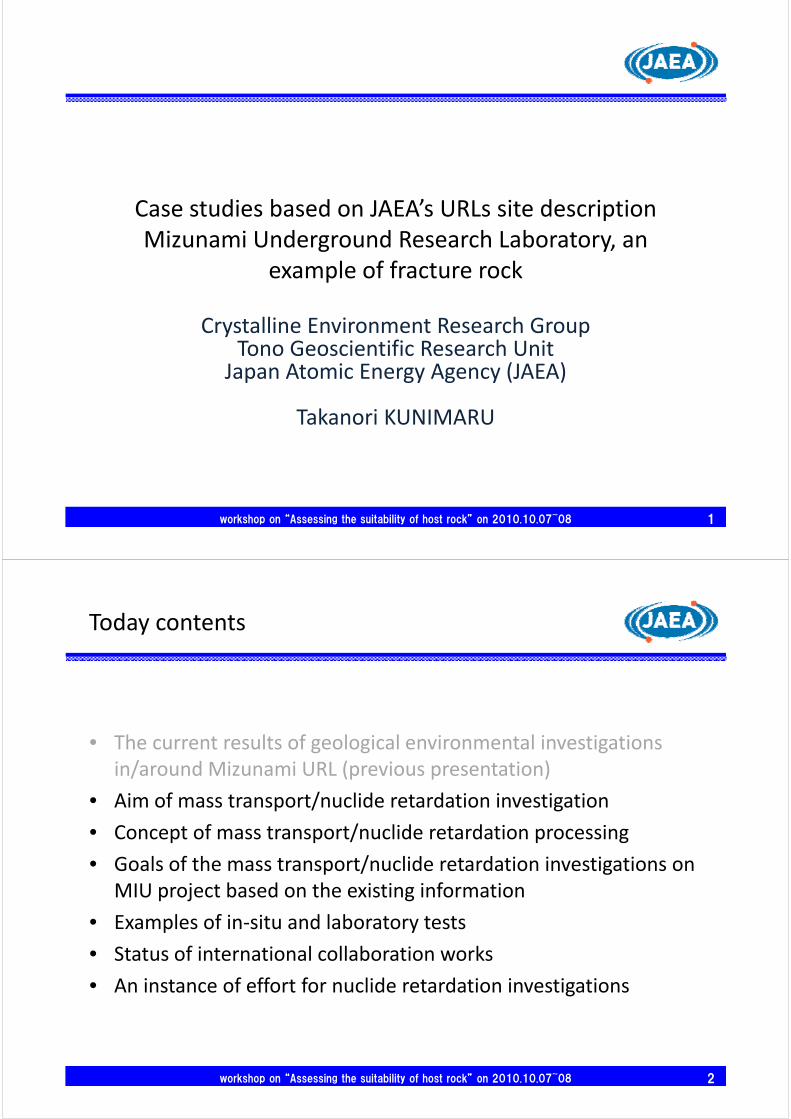
Case studies based on JAEA’s URLs site descriptionpMizunami Underground Research Laboratory, an
example of fracture rockp
Crystalline Environment Research GroupT G i ifi R h U iTono Geoscientific Research Unit
Japan Atomic Energy Agency (JAEA)
Takanori KUNIMARU
workshop on “Assessing the suitability of host rock” on 2010.10.07~08 1
Today contents
• The current results of geological environmental investigations in/around Mizunami URL (previous presentation)/ (p p )
• Aim of mass transport/nuclide retardation investigation
• Concept of mass transport/nuclide retardation processingConcept of mass transport/nuclide retardation processing
• Goals of the mass transport/nuclide retardation investigations on MIU project based on the existing informationp j g
• Examples of in‐situ and laboratory tests
• Status of international collaboration works
• An instance of effort for nuclide retardation investigations
workshop on “Assessing the suitability of host rock” on 2010.10.07~08 2

Aim of mass transport / nuclide retardation investigation
• To develop systematic methodology for relevant• To develop systematic methodology for relevantinvestigation and evaluation of structure, whichcontribute to groundwater flow between tunnel wall’scontribute to groundwater flow between tunnel wall sback and 100m ahead, groundwater flow system andmass transport propertiesmass transport properties
to assess for relevance of hydrogeological model and masstransport conceptual model and to update their modelstransport conceptual model, and to update their models
to obtain parameter using on mass transport analysis
to understand mass transport and retardation processes to understand mass transport and retardation processes
workshop on “Assessing the suitability of host rock” on 2010.10.07~08 3
Concept of mass transport processing (1)
Sedimentary Fm.
Aquifer
Host rock
Fractured zone/Fault zone
RepositoryEvaluation of the mass transport properties at a few to
Modified from JNC(1999)
p p pless than hundred meter scales around the drift
workshop on “Assessing the suitability of host rock” on 2010.10.07~08 4
( )

Concept of mass transport processing (2)
100‐1,000mDiffusions in micro fracture
Single water conducting fracture
Micro pore / Micro fracture
Sorption
Sorption coefficientFlow wetted surface
Diffusion / SorptionAperture
Diff i d ti ffi i t
Single water conducting fracture
Rock matrix / Fracture surface
Dispersivity
Advection / Dispersion
Fractured zoneRepository
Diffusion and sorption coefficient
Porosity
Matrix diffusion depth
Flow wetted surface
Channel
Repository
10‐100m
pH・Eh
Chemical composition
Colloid ・Microbe
Geochemical property of GW
Diffusion at dead end pore
Fracture network
10 100m
propertyInfilling mineral
TransmissivityFlow porosity
Aperture
Fracture network
Advection / Dispersion
Fracture density
workshop on “Assessing the suitability of host rock” on 2010.10.07~08 5
process
parameter
Diffusion / sorption in/around the infilling mineral
gPorewaterpressure
Hydraulic interference
Goals of the mass transport and nuclide retardation investigations at MIU project based on the existing information
• Understanding the relation between the heterogeneous geological environments and nuclide retardation– the heterogeneous geological environments are observed in/around the shafts and research galleries at MIU sitein/around the shafts and research galleries at MIU site
• Development of techniques for characterising the mass transport and nuclide retardation– in‐situ and laboratory test
t t l i– mass transport analysis
• To clarify remaining issues in the mass transport and nuclide retardation– a parameter for mass transport and nuclide retardation is diff b i i d l b
workshop on “Assessing the suitability of host rock” on 2010.10.07~08 6
difference between in‐situ and laboratory test
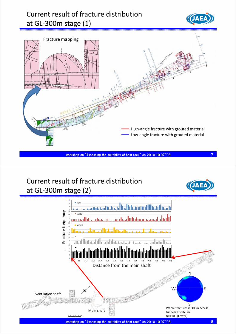
Current result of fracture distributionat GL‐300m stage (1)
Fracture mapping
High‐angle fracture with grouted material
Low‐angle fracture with grouted material
workshop on “Assessing the suitability of host rock” on 2010.10.07~08 7
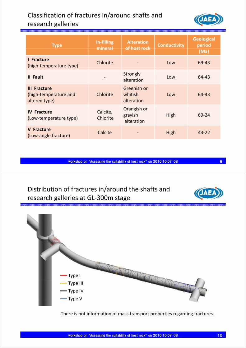
Current result of fracture distributionat GL‐300m stage (2)
15
NW系頻
0
5
10
15
NE系頻度
cy
5
10
15
NNW系頻度
0
5
10 NW系頻度
re frequen
c
15
20
合計頻
0
5
10
15
その他頻度
0
Fractur
0
5
10
1.6 8.0 14.5 21.6 28.7 35.9 42.0 49.0 55.9 62.4 68.8 75.2 82.6 90.0 96.2
対象切羽の水平坑道延長距離 (m)
頻度
Distance from the main shaft
EW
N
S
EWVentilation shaft
workshop on “Assessing the suitability of host rock” on 2010.10.07~08 8
Whole fractures in 300m access tunnel (1.6‐96.0m)N=1103 (Lower)
Main shaft
Classification of fractures in/around shafts and research galleries
TypeIn‐filling mineral
Alteration of host rock
ConductivityGeological period
mineral of host rock(Ma)
I Fracture(high‐temperature type)
Chlorite ‐ Low 69‐43( g p yp )
II Fault ‐Strongly alteration
Low 64‐43
III F t G i hIII Fracture(high‐temperature and altered type)
ChloriteGreenish or whitishalteration
Low 64‐43
IV Fracture(Low‐temperature type)
Calcite,Chlorite
Orangish or grayishalteration
High 69‐24
V Fracture(Low‐angle fracture)
Calcite ‐ High 43‐22
workshop on “Assessing the suitability of host rock” on 2010.10.07~08 9
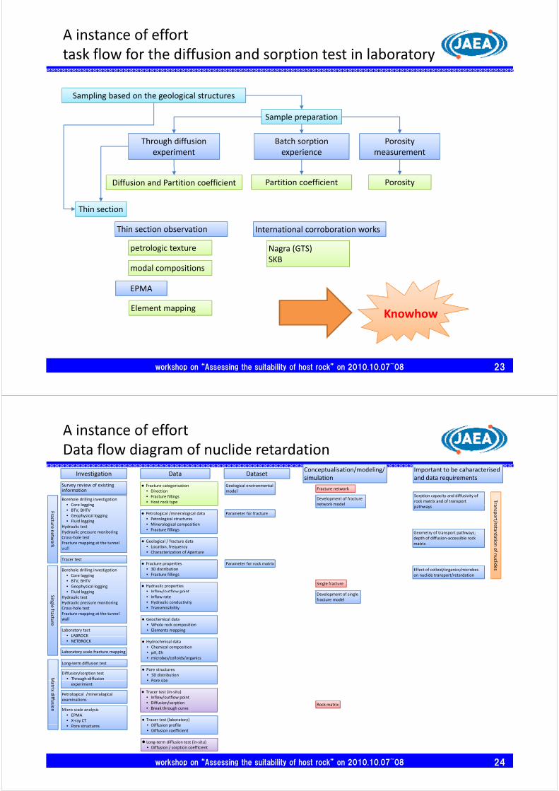
Distribution of fractures in/around the shafts and research galleries at GL‐300m stage
Type I
Type III
Type IV
Type VType V
There is not information of mass transport properties regarding fractures.
workshop on “Assessing the suitability of host rock” on 2010.10.07~08 10

Distribution of the groundwater chemistry around Mizunami URL
MIZ‐1
MSB‐2
MSB‐4
DH‐15
workshop on “Assessing the suitability of host rock” on 2010.10.07~08 11
Investigation scale and items
hydrologicalcharacterisation
Tracer test Tracer testLarge-scale lab.
testFracture internal
structureLong term
diffusion testSorption anddiffusion test
Pore structure inrock matrix
Rock matrix(~a few 10cm)
Investigation items
Invastigaton scaleFracture network(~a few tens of m)
Single water conducting fracture(~about 5m)
characterisation test structure diffusion test diffusion test rock matrixIn-situ In-situ In-situ Lab. test Lab. test In-situ Lab. test Lab. test
Fracture filling materials O OFracture density / aperture O O O
Hydraulic pressure O O
Geological property of fracture
Hydrological property
In-situ/Lab. test
Hydraulic pressure O OT/K/S/Ss O O OWCF location / frequency O OHydraulic connectivity O O
Hydro-transport aperture ● ● ●Dispersivity ● ● ●se
t
Mass transport parameter
In‐si
In‐si
Lab
Lab
Flow porosity ● ● ●Flow wetted surface ● ● ●Fracture 3D distribution O
Diffusion coefficient ● ● O OSorption coefficient ● ● O OEff ti it O C O
Da
ta/d
ata
s
Parameter on diffusion / sorption in rock matrix
itu te
itu te
b. te
s
b. te
s
Effective porosity O C OMatrix diffusion depth ● ● O OPore structure O
O O O
Colloid O O O
Geochemical property of groundwaterWater chemistry(pH, Eh, chemical composition, etc.)
est
est
st st
Colloid O O OMicrobe O O O
○: Date is observed●: Data is calculated
workshop on “Assessing the suitability of host rock” on 2010.10.07~08 12

Examples of in‐situ and laboratory tests1) pore structure and elements mapping
Inada granite
Low High
X-ray CT
3D i li ti f t t b X CT
workshop on “Assessing the suitability of host rock” on 2010.10.07~08 13
3D visualization of pore structures by X‐ray CT
X‐ray CT and EPMA analysis of granite (IRI, 2007)
Examples of in‐situ and laboratory tests2) pore structure and elements mapping
FK-fd
Pl
Qz
Fe Cs
Qz
Bi
7 68mm
K
7.68mmSi
KCs Cs
Si
SiSi
Sorption of Cs+ on edge part showing low concentration of K+
Cs selectively absorb on biotite rim
workshop on “Assessing the suitability of host rock” on 2010.10.07~08 14
EPMA analysis (IRI, 2007)

Examples of in‐situ and laboratory tests3) Diffusion experiment
inle
t
Cs con
reserv o
Inletreservior
Outletreservior
Inlet reservoir
Outlet reservoir
entra
tion
in in
r (μm
ol/L
)
centration in ioir (μm
ol/L)
Tracer-depletion and breakthrough curveTh h diff i i t
Rock sample C
s co
nce
rese
rvoi
r in outlet
Tracer depletion and breakthrough curveThrough-diffusion experiment
rock
en
tratio
n in
in
g)
Advantage It is easy to estimate for test interval Cheaper than in‐situ test
Depth profile
Cs
conc
e(m
mol
/kg Cheaper than in situ test
Many samples are tested simultaneouslyDemerit Boundary conditions are different
workshop on “Assessing the suitability of host rock” on 2010.10.07~08 15
Depth profileBoundary conditions are different between in‐situ and laboratory
Examples of in‐situ and laboratory tests4) Example of tracer experiment (cross hole test)
G l• Goal Developing the concept of selecting test location and
test procedure, etc. Fracture network Fracture network Single fracture
Confirmation of applicability to the test equipment.
workshop on “Assessing the suitability of host rock” on 2010.10.07~08 16
JAEA had experienced at Kamaishi.

Examples of in‐situ and laboratory tests5) Example of tracer experiment under the flow controlled
Low permeability single fracture Background of hydraulic gradient Background of hydraulic gradient Short and Long term experiment
Isolate channel with double packer
Create no‐flow boundary Create no‐flow boundary using slot‐drill holes covering fracture on drift wall
Create no‐flow boundary D ill l di t
yusing boreholes
Drill large diameter boreholes along fracture
workshop on “Assessing the suitability of host rock” on 2010.10.07~08 17
Channel
Current status of in‐situ investigations at GL‐300m stage
Borehole investigation for the faultBorehole investigation for the fault study
Borehole investigation for selecting a tracer test area
LSFD (Lower Sparsely Fractured Domain)
workshop on “Assessing the suitability of host rock” on 2010.10.07~08 18
UHFD (Upper Highly Fractured Domain)
Major Fault

Strategy and methodology for selecting tracer test location
• To clarify the relation between geological structures and massTo clarify the relation between geological structures and mass transport properties.
– Laboratory testy
– Predictive borehole investigation
• To select a target of the geological structure for the tracer testTo select a target of the geological structure for the tracer test (mass transport investigation).
– Part of the matrix in/around host rocks
– Fault and fracture
• Fault
• Single fracture or fracture network
– Predictive modeling and analysis
workshop on “Assessing the suitability of host rock” on 2010.10.07~08 19
g y
Remained issue for in‐situ tracer test
It is possible to evaluate the flow porosity contributed to advection.
It is limited to apply a result of tracer test to performance assessment
The conductivity of target fracture observed in tracer test is higher than the conductivity of an important fracture regarding performance assessment.
It i diffi lt t i ti t th l d ti it f t d th It is very difficult to investigate the low conductivity fracture under the natural conditions.
A conductivity of target fractures investigated is higher than important fracture for mass transport analysis. The internal structure may be different.
The result of diffusion coefficient evaluated by in‐situ test tends to be higherthan that evaluated by the laboratory test (one of the internationalthan that evaluated by the laboratory test (one of the international remaining issues).
Hydrological condition during tracer test is different from natural groundwater flow.
It is unsuitable to evaluate the flow wetted surface.
It is not enough to understand the mass transport processing
workshop on “Assessing the suitability of host rock” on 2010.10.07~08 20
It is not enough to understand the mass transport processing.
The parameters observed in tracer test might be unique characteristics.

Status of international collaboration works (1)1) Long term diffusion test at GTS
Over coring and core material// / / /http://www.grimsel.com/gts‐phase‐vi/ltd/ltd‐phase‐i‐update
Layout of the long term diffusion test at GTS
Results of diffusion profiles
A. Möri, P. Soler, K. Ota, V. Havlova(2007):’Grimsel Test Site Phase VI, LTD WP 1: Predictive Modelling for LTD Monopole Experiment’, Nagra NAB 07‐42
workshop on “Assessing the suitability of host rock” on 2010.10.07~08 21
http://www.grimsel.com/gts‐phase‐vi/ltd/ltd‐phase‐i‐update
Status of international collaboration works (2)2) Modeling works with LTD project at GTS
Distribution of tracer concentration in the rock matrix predicted by 3D Nflow
Conceptual model for 3D analysis
3H 134Cs127I
Distribution of tracer concentration
H CsI
After 5 yearsA. Möri, P. Soler, K. Ota, V. Havlova(2007):’Grimsel Test Site Phase VI, LTD WP 1: Predictive Modelling for LTD Monopole Experiment’, Nagra NAB 07‐42
A. Möri, P. Soler, K. Ota, V. Havlova(2007):’Grimsel Test Site Phase VI, LTD WP 1: Predictive Modelling for LTD Monopole Experiment’ Nagra NAB 07‐42
Only reference parameter values were used for the comparison.Tracer diffuses in 3D direction. 127I and 134Cs diffuse not only into the rock matrix perpendicular to the injection
Modelling for LTD Monopole Experiment , Nagra NAB 07‐42
workshop on “Assessing the suitability of host rock” on 2010.10.07~08 22
127I and 134Cs diffuse not only into the rock matrix perpendicular to the injection borehole but also upwards and downwards within the BDZ along the borehole.
A instance of efforttask flow for the diffusion and sorption test in laboratory
Sampling based on the geological structures
Sample preparation
Porosity measurement
Through diffusion experiment
Batch sorption experience measurement
Porosity
experiment
Diffusion and Partition coefficient
experience
Partition coefficient
Thin section
Thin section observation International corroboration works
petrologic texture
modal compositions
Nagra (GTS)SKB
EPMA
Element mappingKnowhow
workshop on “Assessing the suitability of host rock” on 2010.10.07~08 23
A instance of effortData flow diagram of nuclide retardation
Investigation
Survey review of existing information
Borehole drilling investigation• Core logging
DataConceptualisation/modeling/simulation
Important to be caharacterisedand data requirements
Sorption capacity and diffusivity of rock matrix and of transport
h
Development of fracture network model
Fracture network Fracture categorisation
• Direction• Fracture fillings• Host rock type
Dataset
Geological environmental model
TraCore logging• BTV, BHTV• Geophysical logging• Fluid logging
Hydraulic testHydraulic pressure monitoringCross‐hole testFracture mapping at the tunnel wall
Fracture n
etwork
Petrological /mineralogical data• Petrological structures• Mineralogical composition• Fracture fillings
Geological / fracture data• Location, frequency
pathwaysnetwork model
Parameter for fracture
Geometry of transport pathways; depth of diffusion‐accessible rock matrix
ansport/retard
ation owall
Tracer test
• Characterization of Aperture
Fracture properties• 3D distribution• Fracture fillings
Hydraulic properties• Inflow/outflow point
D l f i l
Single fracture
Borehole drilling investigation• Core logging• BTV, BHTV• Geophysical logging• Fluid logging
Parameter for rock matrix
Effect of colloid/organics/microbes on nuclide transport/retardation
of n
uclid
es
Single fractu
re Geochemical data• Whole rock composition• Elements mapping
/ p• Inflow rate• Hydraulic conductivity• Transmissibility
Development of single fracture model
Fluid loggingHydraulic testHydraulic pressure monitoringCross‐hole testFracture mapping at the tunnel wall
Laboratory test• LABROCK
M
Hydrochmical data• Chemical composition• pH, Eh• microbes/colloids/organics
Pore structures• 3D distribution• Pore size
LABROCK• NETBROCK
Laboratory scale fracture mapping
Long‐term diffusion test
Diffusion/sorption test• Through‐diffusion
Matrix d
iffusio
n
Tracer test (in‐situ)• Inflow/outflow point• Diffusion/sorption• Break through curve
• Pore size
Tracer test (laboratory)Diff i fil
Rock matrix
gexperiment
Petrological /mineralogical examinations
Micro scale analysis• EPMA• X‐ray CT
workshop on “Assessing the suitability of host rock” on 2010.10.07~08 24
Long‐term diffusion test (in‐situ)• Diffusion / sorption coefficient
• Diffusion profile• Diffusion coefficient
• Pore structures

Conclusion (1)
Important aims and investigation items in MIU project are
• Understanding the relation between the heterogeneous geological environments and nuclide retardation
– Relation between the fracture types and mass transport propertiesporosityporosity
diffusion and sorption properties, etc.
– Understanding the depth dependency of nuclide retardationUnderstanding the depth dependency of nuclide retardationGL ‐300m and ‐500m access/research gallery
– An important characteristic in performance assessment po ta t c a acte st c pe o a ce assess e tshould be clarified.Geological environments
workshop on “Assessing the suitability of host rock” on 2010.10.07~08 25
Mass transport properties
Conclusion (2)
• Establish the transferability of laboratory‐derived solutetransport/retardation data to in‐situ conditions– To obtain the in‐situ data by using shafts and research galleries
– To obtain the laboratory scale data by using the facilities of ENTRY and QUALITY in Tokai worksQ
– International collaboration works
• Establish the strategies of nuclide retardation investigations– Development of the task flow for nuclide retardation investigations
– Development/update of the data flow diagram for nuclide retardation
workshop on “Assessing the suitability of host rock” on 2010.10.07~08 26

Discussion points
• How do you think the goals of mass transport and nuclide retardation investigations on MIU project?– Whether a similar research has already been performed or not?
• How should be decided the (in‐situ) test location?– What is a degree of conductivity for applicable tracer test?
– It is important that the hydraulic pressure is stable for the long term diffusion experience. How can the test condition be allowed?
• Necessity of considering the near field effects (e g EDZ)• Necessity of considering the near field effects (e.g. EDZ).
workshop on “Assessing the suitability of host rock” on 2010.10.07~08 27
Related Documents