REVISION OF TRI-SERVICE REGULATORY DESIGN MANUAL "STRUCTURES TO RESIST THE EFFECTS OF ACCIDENTAL EXPLOSIONS" (TM 5-1300, NAVFAC P-397, AFM 88-22) C Angelo Castellano, Joseph Caltagirone, ARRADOM Frederick E. Sock, Norval Dobbs, Ammann & Whitney ABSTRACT Initial guidance in the field of protective structures design was provided in 1969 with the publication of the Tri-Service Design Manual 'Structures to Resist the Effects of Accidental Explosions" (TM 5-1300, NAFVAC P-397, AFM 88-22). The manual presents procedures for determining the blast effects resulting from an explosion and techniques for the design of reinforced concrete structures subjected to blast loads. A considerable amount of data, much of it not covered in the current manual, has been accumulated since its publication. This information has brought about the urgent requirement for revising the manual. This paper briefly describes the topics in the manual that will be revised, those that will be added, the format of the new manual, and the various committees set up to oversee the revision. 41035

Welcome message from author
This document is posted to help you gain knowledge. Please leave a comment to let me know what you think about it! Share it to your friends and learn new things together.
Transcript
REVISIONOF
TRI-SERVICE REGULATORY DESIGN MANUAL
"STRUCTURES TO RESIST THE EFFECTS OF ACCIDENTAL EXPLOSIONS"(TM 5-1300, NAVFAC P-397, AFM 88-22)
C
Angelo Castellano, Joseph Caltagirone, ARRADOM
Frederick E. Sock, Norval Dobbs, Ammann & Whitney
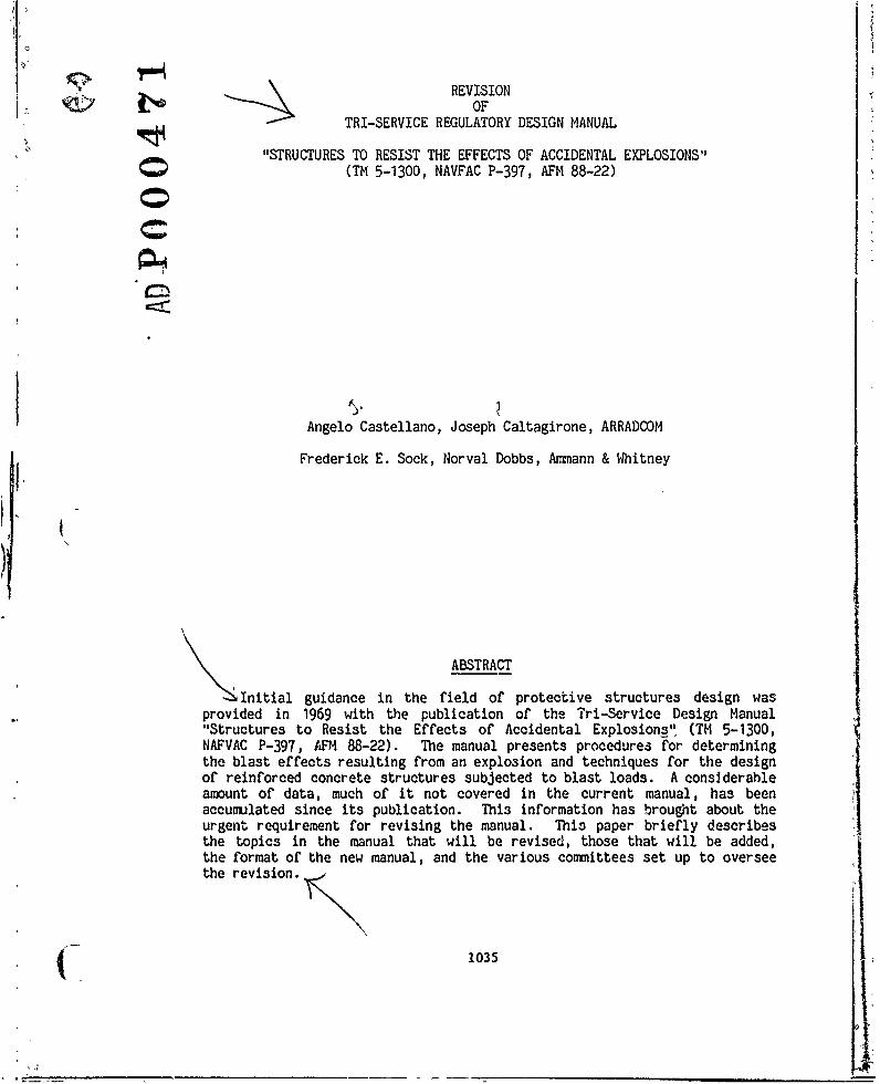
ABSTRACT
Initial guidance in the field of protective structures design wasprovided in 1969 with the publication of the Tri-Service Design Manual'Structures to Resist the Effects of Accidental Explosions" (TM 5-1300,
NAFVAC P-397, AFM 88-22). The manual presents procedures for determiningthe blast effects resulting from an explosion and techniques for the designof reinforced concrete structures subjected to blast loads. A considerableamount of data, much of it not covered in the current manual, has beenaccumulated since its publication. This information has brought about theurgent requirement for revising the manual. This paper briefly describesthe topics in the manual that will be revised, those that will be added,the format of the new manual, and the various committees set up to overseethe revision.
41035

REVISIONOF
TRI-SERVICE REGULATORY DESIGN MANUAL
"STRUCTURES TO RESIST THE EFFECTS OF ACCIDENTAL EXPLOSIONS"
Introduction
The initial guidance in the highly specialized and complex field of
protective design was provided in 1969 when the Tri-Service Manual,
"Structures to Resist the Effects of Accidental Explosions" (ref. 1) was
published. The manual presents procedures for determining the blast
effects resulting from an accidental explosion and also techniques for the
design of reinforced concrete structures which will provide protection for
personnel, equipment and other explosive items.
A considerable amount of data (published as technical documents and
others yet to be published) has been accumulated since the development of
the Tri-Service Manual. Although some of this data updates the information
contained in the manual, most of it deals with topics not covered
initially.
Efforts by the Army, Navy, Air Force, and Private Industry in the area
of blast effects and structural design created the urgent need for the
revision of the manual to include recently published data and additional
information. The publication of the Tri-Service Manual was considered a
major step forward in the field of explosion-resistant protective design.
The revision of the manual and the addition of newly developed technology
will greatly improve this important document.
1036 (

This paper describes qualitatively and in a concised form, the various
topics in the manual that will be updated. Additional topics to be
included will also be described briefly. The functions and activities of
the various committees set un to oversee the revision of the manual will be
presented.
Organization of Committees
Figures 1 and 2 show an organization chart of the various institutions
and individuals involved in the revision and update of the Tri-Service
Manual. The revision of the manual is sponsored by the Department of
Defense Explosives Safety Board (DDESE). The U.S. Army Armament Research
and Development Command (ARRADCOM) provides administrative and technical
guidance to the Steering Committee. The ARRADCOM team has also the task of
preparing the revised manual througn a contractor, Ammann & Whitney,
Consulting Engineers, New York, N.Y., and their subcontractor, Southwest
Research Institute, San Antonio, Texas.
Steering Committee
The Steering Committee, comprised of experts from the Department of
Defense Explosive Safety Board (DDESB), Army, Navy, Air Force and the
Office of the Chief of Engineers (OCE) (fig. 2), meets twice a year to
review the findings and recommendations of the two subcommittees; namely,
Blast Technology and Design Application. The Steering Committee will
periodically review the revision of the manual.
1037
______

Blast Technology arid Design Application Subcommittees
These subcommittees consist of personnel from the Army, Navy, Air
Force, DDESB, COE and private industry (fig. 2). They meet every four
months to identify new technological advances and to recommend appropriate
revisions. They will also review the revised manual at the 50 percent
stage of completion and the final draft.
Topics to be Revised
Two of the most frequently used design aids in the Tri-Service Manual
are Figures 4-5 and 4-12. They show the variations of pressures, impulses, Vvelocities and other parameters of shock waves with scaled distances based
upon tests performed with TNT. Since their development and incorporation
into the manual in 1969, additional theoretical and empirical information 1Jhas become available, some of it published in the manual prepared by
Southwest Research Institute (SWRI) for the Department of Energy (ref. 2).(
Some of the curves illustrated in the figures have been revised and refined
by C. Kingery of the Ballistic Research Laboratories (BRL), and these new
curves will be incorporated in the revised version of Figures 4-5 and 4-12
(figs. 3 and 4).
Other figures and charts to be revised include, but are not limited
to, the following:
1. Figure 4-6 (fig. 5), Reflected Pressure Coefficient vs. Angle of
Incidence - Will be replaced by new curves for pressure and
impulse variation.
1038 (
(7

2. Figure 4-63, Exterior Leakage Pressure vs. Ground-Scaled Distance
- The existing curves in the manual are out-dated and will be
replaced. The bulk of the new data will be extracted from CEL
Report TR R828 (ref. 4).
3. Figure 4-65, Maximum Mean Pressure in a Partially Vented Chamber -
At present, the four existing curves, namely, NOL, Weibull, SWRI
and TM 5-1300 (fig. 6), depict different conditions for mean
pressure in a chamber. These curves will be analyzed and
additional data from tests performed in Norway and the United
Kingdom will be added to form a revised curve.
4. Figure 4-72, Leakage Pressure Coefficient vs. Pressure
Differential - Recent test data will be examined for the revision
of this figure (fig. 7), which is considered to be inadequate.
5. The human tolerance table will be updated, using recent data
published by the Lovelace Foundation.
Besides the revision of other tables and figures in the manual, some
topics have to be updated appropriately. One such example is the effect on
explosive output due to shape of explosive and number of charges. This
data which was previously referred to as "TNT Equivalency" will now be
referred to as Equivalent Charge Weight with the effect produced by the
variation of explosive material referred to as TNT equivalency.
.1039
Additional Topics to be Included
Since the development of the Tri-Service Manual, ARRADOM and other
organizations of the Army, Navy and Air Force have done a considerable
number of studies on blast effects and the blast-resistant capacities of
various structural elements. These studies will be reviewed and the topics
pertinent to the subject of the manual will be incorporated. Some of these
topics are listed in Figure 8.
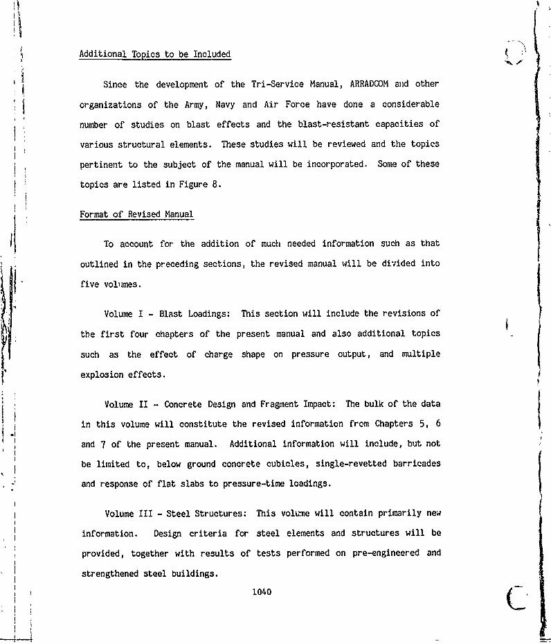
Format of Revised Manual
To account for the addition of much needed information such as that
outlined in the preceding sections, the revised manual will be divided into
five volumes.
Voum I- lat oains:This section will include the revisions of
the first four chapters of the present manual and also additional topics
such as the effect of charge shape on pressure output, and multiple
explosion effects.
Volume II - Concrete Design and Fragment Impact: The bulk of the data
in this volume will constitute the revised information from Chapters 5, 6
and 7 of the present manual. Additional information will include, but not
be limited to, below ground concrete cubicles, single-revetted barricades
and response of flat slabs to pressure-time loadings.
Volume III - Steel Structures: This volw-e will contain primarily new
information. Design criteria for steel elements and structures will be
provided, together with results of tests performed on pre-engineered and
strengthened steel buildings.
1040

1'-
Volume IV - Other Factors to be Considered in Explosive Facility
Design: Chapter 10 of the current manual will be revised in this volume.
Data will also be provided on safe separation distances between explosive
items, blast-resistant capacities of glass windows and frames, and
earth-covered magazines, etc.
Volume V - Computer Programs and Guide: Like Volume III, this section
is new and will deal with the computer programs currently available to the
Army, Navy and Air Force. The listing of the highly specialized programs
(i.e., those programs written for blast design) will be provided in this
volume.
It is hoped that the division of the revised and updated manual into
five volumes will allow for a detailed and vivid presentation of the
various topics in this highly complex field of blast design. References
will be provided in each volume in the event that additional information in
any particular topic is required.
Conclusions
The revision and update of the manual will be completed by the end of
1983. By then, It is anticipated that the five volumes that constitute the
manual will contain the most recent data available in the area of
protective design. Memos have been sent out to various Division Engineers
and Commanders of the Army, Navy and Air Force asking them to identify any
shortcomings of the present manual. Their responses have been taken into
account in order that the final manual will satisfy the needs of the
various users.
( 1041

REFERENCES
1. "Structures to Resist the Effects of Accidental Explosions (withAddenda)", Department of the Army Technical Manual TM 5-1300,Washington, D.C., June 1969.
2., "A Manual for the Prediction of Blast and Fragment Loadings onStructures", DOE/TIC-11268, U.S. Department of Energy, Amarillo,Texas, November 1980.
3. GLADSTONE and DOLAN, "Effects of Nuclear Weapons", 3rd Edition,1977.
4. KEENAN, W., and TANCRETO, J.E., "Blast Environment from Fully andPartially Vented Explosions in Cubicles", Technical Report R828,prepared by Civil Engineering Laboratory, Naval ConstructionBattalion Center, Port Hueneme, California, for Department of theArmy, Picatinny Arsenal, Dover, New Jersey, November 1975.
1042
.1I

wI
w0
C01w
<40 0 <_r U A
0.0S2 L.
CI) 0
w c!
0 0
IDC >:
o~ 4-w-
ww
0
40in cj< D

STEERING CONITTEE
Dr. T. Zaker, DDESB
W.L. Armstrong, NCEL
W.C. Buchholtz, AFESC
Lt. Col. W. Mills, COE
Major S. Hawn, AFESC
L.W. Saffian, ARRADGOM
SUB-COMMITTEESBlast Technology Design Application
C.N. Kingery, BRL, ARRADCOM P.D. Price, DDESB
R. Lorenz, NSWC W. Keenan, NCEL
Dr. W.E. Baker, SwRI R. Lein, CO"
H.S. Napadensky, IITRI N. Dobbs, A&W
J.P. Caltagirone, ARRADCOM R.L. Wight, OCE
P. Nash, AFESC H.D. Nickerson, NFEC
Cpt. P.L. Rosengren, AFESC
A. Castellano, ARRADCOM
Figure 2. STEERING AND SUB-COMMITTEE MEMBERS
1044

100.00 10
nV
1 U.
4 44tW
I .1~0001
SCALED DISTAN~CE Z- R/W' 1'
Figure 3 Blast Parameter for ;3pherical Free Air Burst of TNT
1045

444 t-0 -.
10000 IM, 3 10
~ I~I:~~ - ,..~-W
!11 1'. U :1! 1: -w
100* IL , i~lit,..
10046

INCIDENT PRESSURE Pso(psI)
12
91 xj.41
10MI Ii t
0.0 I.87 Hl IT w CHI
z M
0d 10 a0 ;0 40 5 0 7 0 9
107

0 IL>~ IL
0- 0
2 I-
_ _s)" _ _ _ _ __?J NVV In~x
_ 1048

*&C/
I "nil I
I
T I.- -
fill75
His I LR V
is I if 444
ij:1. . .... ...
41 11t 4.4
E Irif Vs:CL
lig I,,+
tj Iii* ;,.14, 111 M I JIM
'I I 1.'. 1. 1 t,4" il* 1011 ;;,1 ij JIM50;;, I . I , T - '. I: I , , p.: ti-IF fi ;,t VIM;
I ILI. 1:1.1 1: i4! 1; 1 !1, IT If I
L).1 11111VA 0.4 t . fF' fill -1 4 fillE-L + +"I "It ;"I j I it III Itill !"'I'M 110 MIT 1
LL ji 11411tj 4,1- : i:1 - , iw 1114OP15 III-1i; f, i;l I Iffill Mifilliliffill. 140
4 f 4. f . 4IJit, , . -111, 1 , 1, 1 - J-Jjqfl' + I I IRilfl " it - 'I ;- jilil, ItI 4:1111"il, Pillfill i, III If vf! I I i-I Ill 1, i'Iti - , + is
w 14! 1 if
f, I Ills,
W
+1D 4 IliU) jilMll. 1.11. If -it .!if TIN101 It + I Ifill M t":1111111:1+1If !-,, ;,: 1 1, ;11 1 1 111-1 '14 is, I I "" " ! I!
: 411*lff 'if Iffif j , .'!!*1 1 M I . V, I I fill I Il 4 1 11,011*1 Ill Olf4lfull IiII1,11111M* I p t'. + IM11 TO I 1 1. *4
I : * *NII I "10.41111ti., mt. 1:1i Itif t I It lip1,011m 001111 4 '114 fV-I I+ , , ': I I I
I , 'i f 11 41"t I + 4W, sit .31, lF4w 25
it 11 Willif Hli 1 IIIH I Off "if 111 flu 1111 1: 1 0+11: 1' 1 Jill Jill 11! 1:111 fillIII if 1 111 1 11 1, fill: :1 I lit!
w 4. ; I .", It's I...1I I M.-F. if M IDIOM
fill 11 *+ *+111fli i"Ib il 11111 1 1 1-1104 Ili, fill 11 .1 +
1.'H P, i"ll "11114 NO 311 i!it 11 10111i I 1 4 1+
M A I 11110 HIM 11 1 111illiff Ili; 11 im
I HIM , 1111111111 M If
I; I I ; I I I Of 0111111,i
lt4JJJt 11010 1! l: Mill
It Ill
1:11fliflillfill :;I 10MIlVii Hl 1111; 1 if-!, 111111 111 ill 'Offillill I W: Jill11-111131 If.! H 111111 :111 100
lit,;"; Ill!; Hil I if 1.11 11 I'll ifif JIM
+ 111011010 1 1 Ill
If f;ii U gi V t is 4if M I I - i I
I 1101IIIIIIIIIIII MIN!11111111MIM111"M DOE 1 111 !1, i50 100
PRESSURE DIFFERENTIAL P-P! (psi)
Figure 7 Leakage Pressure Coefficient vs. Pressure Differential
1049

1. Full containment and below ground cells and single-revettedbarricades.
2. Overturning of structures subjected to blast loads.
3. Primary fragment penetration and secondary fragment impact.
4. Multiple explosion sources, simultaneous and sequentialdetonations.
5. Design of structural steel buildings.
6. Pre-engineered and strengthened steel buildings; structural steelelements (ARRADOM reports).
7. Computer analyses of frame structures and other structuralelements.
8. Tests performed on cold-formed steel panels, window frames andglass, including performance specifications for blast windows.
9. TNT equivalencies of explosives and propellants.
10. Leakage pressures due to venting.
11. Ground shock effects.
12. Blast environment due to explosions within structures.
13. Blast environment within structures due to explosions outside thestructure.
14. Blast door design. Results of ESKIMO test series.
15. Design of reinforced concrete flat slabs, beam and column.
16. Suppressive shielding design.
Figure 8. New data to be incorporated in the Protective Design Manual
1050
Related Documents