1 halcorocktools.com A–Z OF DRILLING

Welcome message from author
This document is posted to help you gain knowledge. Please leave a comment to let me know what you think about it! Share it to your friends and learn new things together.
Transcript
1
halcorocktools.com
A–ZOF DRILLING
2 3
1 INTRODUCTION 3
2 COMPRESSED AIR 17
3 EQUIPMENT SELECTION 27
4 OPERATING DTH EQUIPMENT 37
5 TROUBLESHOOTING 55
6 DRILL BIT CARE 63
7 APPENDICES 73
CONTENTS INTRODUCTION
HAMMER AND DRILL BIT DEVELOPMENT
APPLICATIONS
ADVANTAGES ANDCOMPARATIVE COSTS
4 5
Valved Hammer
Valveless Hammer
Valve
The Down-the-hole or DTH hammer is used for drilling holes through a wide range of rocks and associated materials and the variety of applications to which it can be put has extended and continues to extend well beyond the original conception of primary blast hole drilling. Andre Stenuick of Stenuick Freres Belgium was first to start commercialising the product in 1950.
Halco in close co-operation with Stenuick Freres actually pioneered the development and distribution of the down-the-hole hammer, primarily throughout the UK, Australia, New Zealand, Africa and India in the 1950’s.
Prior to their introduction in the early 1950’s blast hole drilling was normally carried out with drifter equipment whilst water well drilling in hard formations was done by cable tool rigs or rotary rigs using rock roller bits (Tricones).
However, because drifter drilling becomes progressively slower with increasing depth, unlike DTH hammers, and because the latter can drill in one day what a cable tool rig takes weeks to complete, the quarrying, water well, site investigation, civil engineering and mining industries throughout the world have become more and more aware of the advantages to be gained from using DTH hammers, not only as an alternative to drifters but because of the higher performances when compared to conventional rotary drilling.
The DTH hammer concept proved so popular that established manufacturers of drifter steels, bits and accessories, followed Halco’s lead and developed their own range of DTH hammers and bits.
“Down the hole” refers to where the hammer action occurs when compared to drifter hammers, which hammer on top of the drill string. The DTH hammer piston always makes direct contact with the drill bit and there is generally no loss of transmitted energy as the hammer drills deeper, as is the case with drifter (top hammer) rigs.
Penetration rates with DTH hammers are almost directly proportional to air pressure therefore doubling the air pressure, will result in approximately double the penetration.
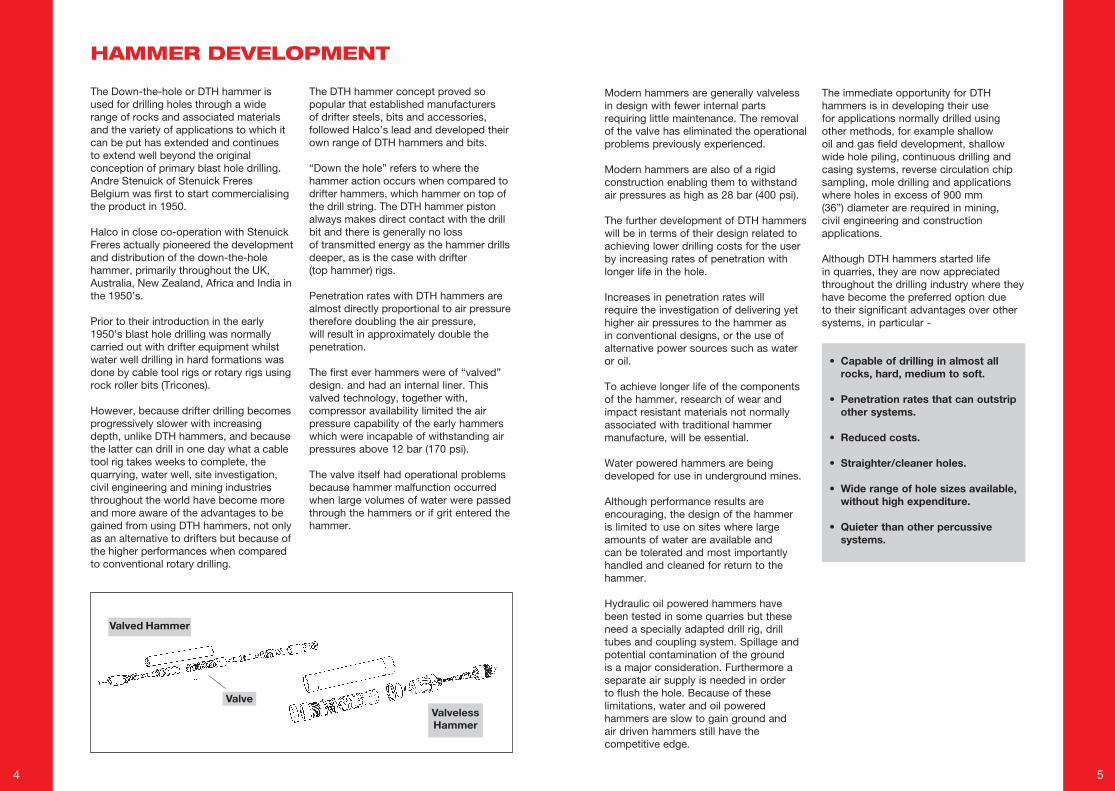
The first ever hammers were of “valved” design. and had an internal liner. This valved technology, together with, compressor availability limited the air pressure capability of the early hammers which were incapable of withstanding air pressures above 12 bar (170 psi).
The valve itself had operational problems because hammer malfunction occurred when large volumes of water were passed through the hammers or if grit entered the hammer.
Modern hammers are generally valveless in design with fewer internal parts requiring little maintenance. The removal of the valve has eliminated the operational problems previously experienced.
Modern hammers are also of a rigid construction enabling them to withstand air pressures as high as 28 bar (400 psi).
The further development of DTH hammers will be in terms of their design related to achieving lower drilling costs for the user by increasing rates of penetration with longer life in the hole.
Increases in penetration rates will require the investigation of delivering yet higher air pressures to the hammer as in conventional designs, or the use of alternative power sources such as water or oil.
To achieve longer life of the components of the hammer, research of wear and impact resistant materials not normally associated with traditional hammer manufacture, will be essential.
Water powered hammers are being developed for use in underground mines.
Although performance results are encouraging, the design of the hammer is limited to use on sites where large amounts of water are available and can be tolerated and most importantly handled and cleaned for return to the hammer.
Hydraulic oil powered hammers have been tested in some quarries but these need a specially adapted drill rig, drill tubes and coupling system. Spillage and potential contamination of the ground is a major consideration. Furthermore a separate air supply is needed in order to flush the hole. Because of these limitations, water and oil powered hammers are slow to gain ground and air driven hammers still have the competitive edge.
The immediate opportunity for DTH hammers is in developing their use for applications normally drilled using other methods, for example shallow oil and gas field development, shallow wide hole piling, continuous drilling and casing systems, reverse circulation chip sampling, mole drilling and applications where holes in excess of 900 mm (36”) diameter are required in mining, civil engineering and construction applications.
Although DTH hammers started life in quarries, they are now appreciated throughout the drilling industry where they have become the preferred option due to their significant advantages over other systems, in particular -
• Capable of drilling in almost all rocks, hard, medium to soft.
• Penetration rates that can outstrip other systems.
• Reduced costs.
• Straighter/cleaner holes.
• Wide range of hole sizes available, without high expenditure.
• Quieter than other percussive systems.
HAMMER DEVELOPMENT

6 7
Drilling into the ground, the eccentric bit rotates outwards to drill a larger diameter hole than the following casing.
After reaching the required cased depth the drill string is rotated in the opposite Direction, the eccentric bit is then withdrawn into the Casing.
This enables the entire drill string to be pulled out, leaving the casing in situ in the bedrock.
Drilling can then be continuedusing a standard DTH button bit through the casing.
1
3
2
4
Some applications for conventional DTH hammers include blast hole drilling, water well and geothermal drilling, mineral exploration, seismic investigation, intermittent sampling and a wide variety of civil engineering and underground mining applications.
Civil engineering applications include piling, site investigation, ground consolidation and anchoring, post holes, de-watering, earthing rod installation, micro-piling and monitoring ground movement and ground contamination.
Underground mining applications include rockbolting, cable anchoring, blasting, cut out raises, communication and ventilation raises, rescue shafts, instrumentation installations and underground service passages.
The down-the-hole hammer is now probably the most versatile drilling method available for most applications because it can be used in medium and hard formations enabling them to be used in conditions previously exclusive to rotary, drifter and coring techniques.
REVERSE CIRCULATION
DRILL BIT DEVELOPMENT
Rapid advances in drill bit technology have also occurred throughout the last 40 years.
The first type of drill bit used with down the hole hammers was a “cross bit” design. Four chisel shaped lengths of tungsten carbide were brazed into the bit body.
The action of brazing preset stresses within the drill bit thereby limiting its life.
A further disadvantage of the cross bit was that the majority of the carbide was situated around the centre of the bit face and not towards the outer edge of the drill bit where there is the most rock to cut.
1960’S DESIGN BUTTON BIT
MODERN DESIGN BUTTON BIT
1960’S DESIGN CROSS BIT
APPLICATIONS OVERBURDENS SYSTEMS
Soft soil is normally drilled with augers or by the rotary method but DTH hammers have adapted to soft conditions by being able to drill and case the hole simultaneously using an eccentric bit which can be withdrawn on completion of the bore hole, leaving the case in situ, thus preventing the hole collapse.
The systems achieve this by enabling the down the hole bit string and casing to be lowered simultaneously.
A down the hole hammer is used to which is fitted a driver and eccentric bit.
Reverse circulation hammers can in most instances carry out continuous sample collection in a fraction of the time necessary with conventional or wireline coring.
CONVENTIONAL HAMMERS
8 9
In the late 1960’s however, the button bit was introduced and this was a landmark in the progress of DTH equipment which led to bit lives previously unheard of.
The button bit design eliminated the primary shortcomings of the cross bit.
Cylindrical button inserts are precision ground to extremely close tolerances and pressed into the drill bit as an interference fit. This resulted in improved carbide insert retention by eliminating brazing stresses and other defects associated with brazing and braze materials.Button inserts are distributed more
efficiently than cross bit inserts by providing more cutting power where it is needed at the outer edge of the drill bit face.
In many cases, the need to sharpen the drill bit was eliminated with the arrival of the button bit and the improved cutting action provided increased drilling rates particularly in hard rocks.
Whilst the cross bit design is still used in some rotary and drifter applications where the rock is very soft, the button bit is now used in virtually every DTH application.
COMPARATIVE VERSATILITY
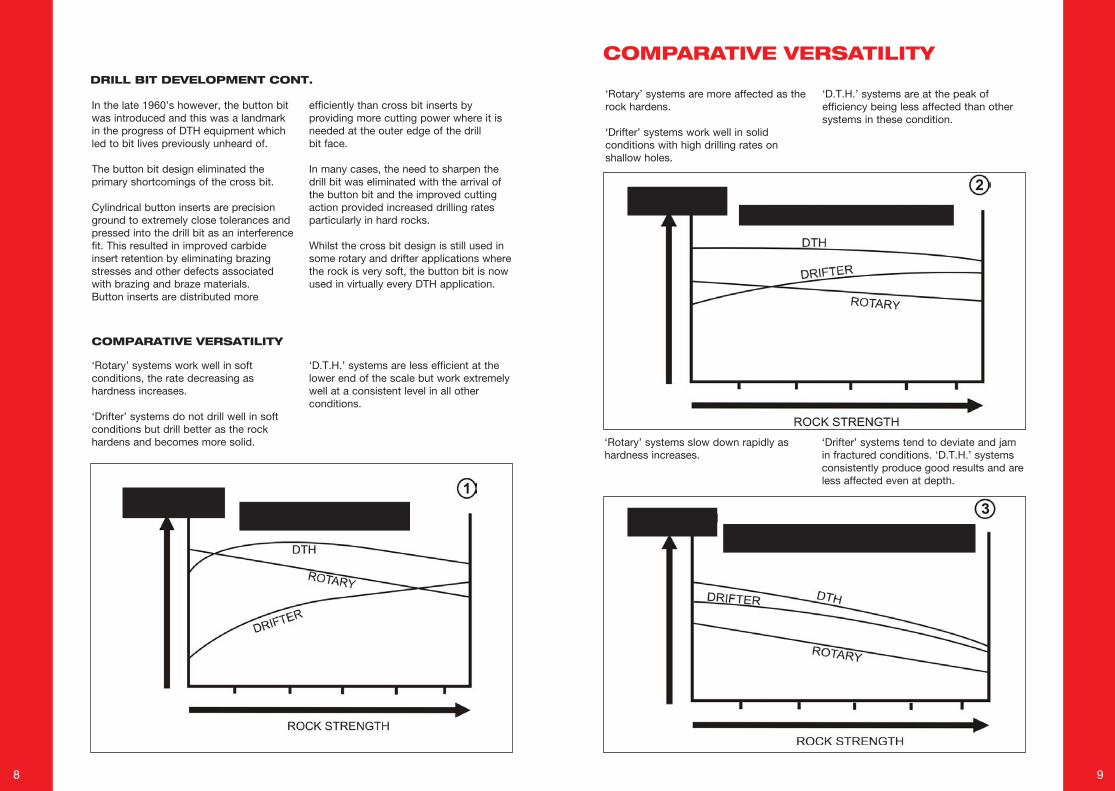
‘Rotary’ systems work well in soft conditions, the rate decreasing as hardness increases.
‘Drifter’ systems do not drill well in soft conditions but drill better as the rock hardens and becomes more solid.
‘D.T.H.’ systems are less efficient at the lower end of the scale but work extremely well at a consistent level in all other conditions.
‘Rotary’ systems are more affected as the rock hardens.
‘Drifter’ systems work well in solid conditions with high drilling rates on shallow holes.
‘D.T.H.’ systems are at the peak of efficiency being less affected than other systems in these condition.
‘Rotary’ systems slow down rapidly as hardness increases.
‘Drifter’ systems tend to deviate and jam in fractured conditions. ‘D.T.H.’ systems consistently produce good results and are less affected even at depth.
COMPARATIVE VERSATILITYDRILL BIT DEVELOPMENT CONT.
10 11
Rotary Drilling relies upon high rotational speeds and thrust without percussion to achieve the desired effect and outputs. Heavy drill collars are sometimes needed to add extra thrust to the bit.
Rotary machines are usually large self contained hydraulically powered units with sufficient weight to provide the thrust on the drill bit to drill the hole.
The harder the rock the greater the thrust required, the heavier the machine, the greater the initial capital outlay, the higher the operating costs.
The same factors apply when hole diameters are increased.
Excessive thrusts can lead to deviation of the bore hole particularly when drilling at angles in bedded formations.
Rotary drilling can be cost effective in soft/medium low abrasive formations but not in medium hard abrasive conditions.
Tricone rotary bits are not suited to holes below 140 mm (5.1/2”) diameter due to the premature destruction of the bearings within the bit and drag bits are only successful in soft formations.
DTH hammers do not require the powerful down thrust and torque of the rotary rig and therefore can be used on lighter, less expensive and more mobile machines.
The low torque and thrust required by the DTH hammer means that rotation head vibration is appreciably less than that created by the rotary method.
Because minimal thrust is applied to the DTH hammer, it deviates from its course very little and drills a straighter hole than the rotary bit.
DTH offers longer bit life and faster penetration rates in medium to hard rock at any depth
DTH hammers drill mixed, hard and medium formations more efficiently than rotary equipment
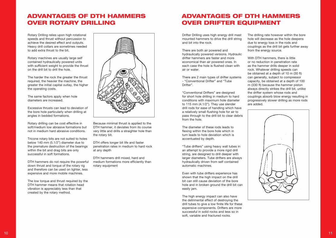
Drifter Drilling uses high energy drill mast mounted hammers to drive the drill string and bit into the rock.
There are both air powered and hydraulically powered versions. Hydraulic drifter hammers are faster and more economical than air powered ones. In each case the hole is flushed clean with air or water.
There are 2 main types of drifter systems - “Conventional Drifter” and “Tube Drifter”.
“Conventional Drifters” are designed for short hole drilling in medium to hard conditions with maximum hole diameter to 115 mm (4.1/2”). They use slender drill rods for ease of handling which have a relatively small flushing hole for air to pass through to the drill bit to clear debris from the hole.
The diameter of these rods leads to flexing within the bore hole which in turn leads to hole deviation which is accentuated by depth.
“Tube drifters” using heavy wall tubes in an attempt to provide a more rigid drill string, are designed to drill deeper with larger diameters. Tube drifters are always hydraulically driven from self contained automatic machines.
Even with tube drifters experience has shown that the high impact on the drill bit can still cause deviation of the bore hole and in broken ground the drill bit can easily jam.
The high energy impact can also have the detrimental effect of destroying the drill tubes to give a low finite life for these expensive components. Drifters are more successful in solid rocks and less so in soft, variable and fractured rocks.
The drilling rate however within the bore hole will decrease as the hole deepens due to energy loss in the rods and couplings as the drill bit gets further away from the energy source.
With DTH hammers, there is little or no reduction in penetration rate as the hammer drills deeper in solid rock. Whatever drilling speeds can be obtained at a depth of 10 m (30 ft) can generally, subject to compressor capacity, be obtained at a depth of 100 m (330 ft) because the hammer piston always directly strikes the drill bit, unlike the drifter system whose rods and couplings absorb blow energy resulting in progressively slower drilling as more rods are added.
ADVANTAGES OF DTH HAMMERS OVER ROTARY DRILLING
ADVANTAGES OF DTH HAMMERS OVER DRIFTER EQUIPMENT
12 13
With DTH, the operator works in relative comfort because the sound of the hammer is muffled in the hole. With the drifter hammer, the operator may be continuously subjected to intense noise.
Clearance of cuttings is more effective with DTH resulting in less recrushing of rock and therefore more efficient drilling. This is achieved in two ways -a) By utilising a smaller annulus between
the drill string and the bore hole.b) By making a greater volume of air
available at the rock face than can be passed through the narrow duct in a drifter rod.
Because they are unable to clear cuttings efficiently at depth, drifters often have to do a certain amount of non productive drilling per hole to ensure they achieve the full required depth.
Larger diameter holes can be drilled with DTH usually with the same size of rig.
Drill tube changing is easier and quicker with DTH because DTH tubes are lighter and do not absorb percussive energy as do drifter rods and couplings which become heated and are far more subject to wear on the threads. Consequently DTH drill tubes can last for years whereas drifter rods and couplings are regarded as major consumable items.
DTH hammers can make use of high pressure air whilst drifters are unable to do so because of the limitations of the drill steel bore.
DTH hammers are kinder to the drill rig because their energy is transmitted to the rock and most vibration is absorbed down the hole. The drifter’s initial transfer of energy takes place on the mast which can be subjected to heavy vibration.
With DTH hammers the operator is immediately aware of any malfunction such as binding or insert breakage by the sound emitted from the bore hole but this is not possible with the drifter due to the intense noise from the drifter head. In the event of changing a DTH hammer, either
for servicing or fitting a different size or type, the DTH conversion can be carried out in a short time without immobilizing the rig. This is not the case with the drifter hammer.
Generally speaking, DTH hammers give way to drifters at depths of less than 10 m where hole diameters below 100 mm (4”) are required due to the faster penetration speeds of the drifter in these conditions.
Many drifter drill rigs can be converted to the advantages of DTH hammer by equipping the drill rig with a rotation gearbox, enabling the rig to drill larger diameter holes than previously possible with a drifter head. On blasting applications, the subsequent increase in burden and spacing provided by a larger diameter hole can result in more rock being produced at less cost and without the capital outlay of a new drill rig.
The ability of the DTH hammer however to generally drill a straighter hole, its quieter operation, lower air consumption than an air powered drifter and more efficient hole cleaning capability are points worthy of consideration, even for short holes of small diameter.
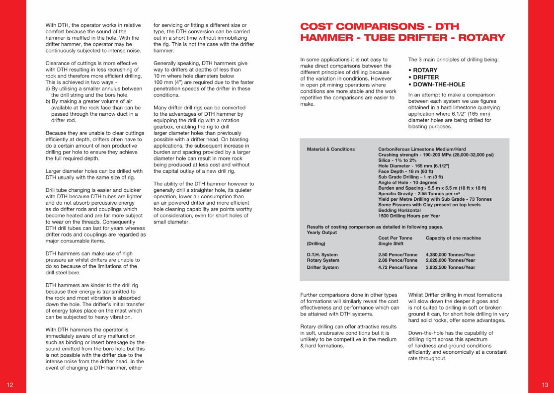
In some applications it is not easy to make direct comparisons between the different principles of drilling because of the variation in conditions. However in open pit mining operations where conditions are more stable and the work repetitive the comparisons are easier to make.
The 3 main principles of drilling being:
• ROTARY• DRIFTER• DOWN-THE-HOLE
In an attempt to make a comparison between each system we use figures obtained in a hard limestone quarrying application where 6.1/2” (165 mm) diameter holes are being drilled for blasting purposes.
Further comparisons done in other types of formations will similarly reveal the cost effectiveness and performance which can be attained with DTH systems.
Rotary drilling can offer attractive results in soft, unabrasive conditions but it is unlikely to be competitive in the medium & hard formations.
Whilst Drifter drilling in most formations will slow down the deeper it goes and is not suited to drilling in soft or broken ground it can, for short hole drilling in very hard solid rocks, offer some advantages.
Down-the-hole has the capability of drilling right across this spectrum of hardness and ground conditions efficiently and economically at a constant rate throughout.
Material & Conditions Carboniferous Limestone Medium/Hard Crushing strength - 190-200 MPa (28,000-32,000 psi) Silica - 1% to 2% Hole Diameter - 165 mm (6.1/2”) Face Depth - 18 m (60 ft) Sub Grade Drilling - 1 m (3 ft) Angle of Hole - 10 degrees Burden and Spacing - 5.5 m x 5.5 m (18 ft x 18 ft) Specific Gravity - 2.55 Tonnes per m³ Yield per Metre Drilling with Sub Grade - 73 Tonnes Some Fissures with Clay present on top levels Bedding Horizontal 1500 Drilling Hours per Year
Results of costing comparison as detailed in following pages.Yearly Output Cost Per Tonne Capacity of one machine(Drilling) Single Shift
D.T.H. System 2.50 Pence/Tonne 4,380,000 Tonnes/YearRotary System 2.88 Pence/Tonne 2,628,000 Tonnes/Year
Drifter System 4.72 Pence/Tonne 3,832,500 Tonnes/Year
COST COMPARISONS - DTH HAMMER - TUBE DRIFTER - ROTARY
14 15
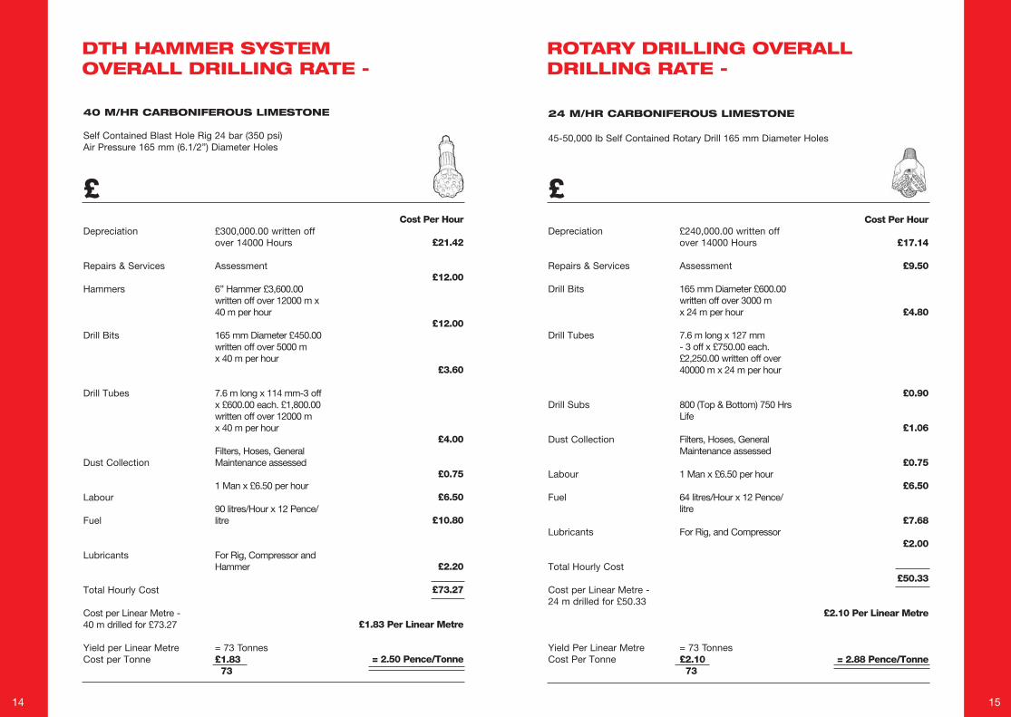
24 M/HR CARBONIFEROUS LIMESTONE
45-50,000 lb Self Contained Rotary Drill 165 mm Diameter Holes
£ £
40 M/HR CARBONIFEROUS LIMESTONE
Self Contained Blast Hole Rig 24 bar (350 psi) Air Pressure 165 mm (6.1/2”) Diameter Holes
DTH HAMMER SYSTEM OVERALL DRILLING RATE -
ROTARY DRILLING OVERALL DRILLING RATE -
Depreciation
Repairs & Services
Hammers
Drill Bits
Drill Tubes
Dust Collection
Labour
Fuel
Lubricants
Total Hourly Cost
Cost per Linear Metre - 40 m drilled for £73.27
Yield per Linear MetreCost per Tonne
£300,000.00 written off over 14000 Hours
Assessment
6” Hammer £3,600.00 written off over 12000 m x 40 m per hour
165 mm Diameter £450.00 written off over 5000 m x 40 m per hour
7.6 m long x 114 mm-3 off x £600.00 each. £1,800.00 written off over 12000 m x 40 m per hour
Filters, Hoses, General Maintenance assessed
1 Man x £6.50 per hour
90 litres/Hour x 12 Pence/litre
For Rig, Compressor and Hammer
= 73 Tonnes£1.83 73
Cost Per Hour
£21.42
£12.00
£12.00
£3.60
£4.00
£0.75
£6.50
£10.80
£2.20
£73.27
£1.83 Per Linear Metre
= 2.50 Pence/Tonne
Depreciation
Repairs & Services
Drill Bits
Drill Tubes
Drill Subs
Dust Collection
Labour
Fuel
Lubricants
Total Hourly Cost
Cost per Linear Metre - 24 m drilled for £50.33
Yield Per Linear MetreCost Per Tonne
£240,000.00 written off over 14000 Hours
Assessment
165 mm Diameter £600.00 written off over 3000 m x 24 m per hour
7.6 m long x 127 mm - 3 off x £750.00 each. £2,250.00 written off over 40000 m x 24 m per hour
800 (Top & Bottom) 750 Hrs Life
Filters, Hoses, General Maintenance assessed
1 Man x £6.50 per hour
64 litres/Hour x 12 Pence/ litre
For Rig, and Compressor
= 73 Tonnes£2.10 73
Cost Per Hour
£17.14
£9.50
£4.80
£0.90
£1.06
£0.75
£6.50
£7.68
£2.00
£50.33
£2.10 Per Linear Metre
= 2.88 Pence/Tonne
16 17
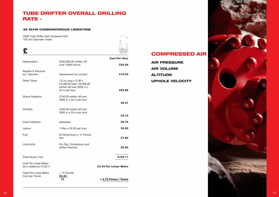
35 M/HR CARBONIFEROUS LIMESTONE
2000 Tube Drifter Self Contained Drill165 mm Diameter Holes
£ COMPRESSED AIR
TUBE DRIFTER OVERALL DRILLING RATE -
Depreciation
Repairs & ServicesInc. Hammer
Driter Tubes
Shank Adaptors
Drill Bits
Dust Collection
Labour
Fuel
Lubricants
Total Hourly Cost
Cost Per Linear Metre - 35 m drilled for £120.11
Yield Per Linear Metre Cost per Tonne
£340,000.00 written off over 14000 Hours
Assessment for contact
7.6 m Long x 3 Off x £2,300.00 each. £6,900.00 written off over 3000 m x 35 m per hour
£740.00 written off over 4000 m x 35 m per hour
£450.00 written off over 5000 m x 35 m per hour
Assessed
1 Man x £6.50 per hour
65 litres/Hours x 12 Pence/litre
For Rig, Compressor and Drifter Hammer
= 73 Tonnes£3.43 73
Cost Per Hour
£24.28
£15.00
£53.66
£6.47
£3.15
£0.75
£6.50
£7.80
£2.50
£120.11
£3.43 Per Linear Metre
= 4.70 Pence / Tonne
AIR PRESSURE
AIR VOLUME
ALTITUDE
UPHOLE VELOCITY
18 19
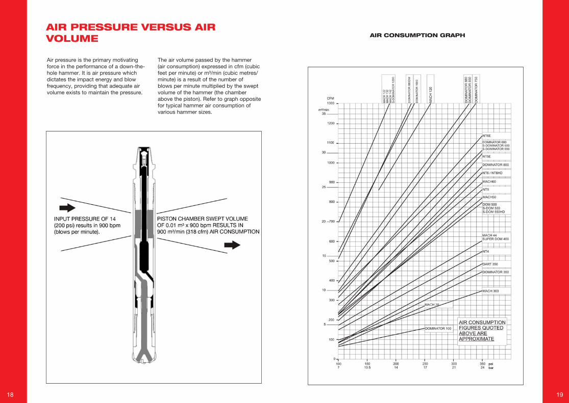
Air pressure is the primary motivating force in the performance of a down-the-hole hammer. It is air pressure which dictates the impact energy and blow frequency, providing that adequate air volume exists to maintain the pressure.
The air volume passed by the hammer (air consumption) expressed in cfm (cubic feet per minute) or m³/min (cubic metres/minute) is a result of the number of blows per minute multiplied by the swept volume of the hammer (the chamber above the piston). Refer to graph opposite for typical hammer air consumption of various hammer sizes.
AIR PRESSURE VERSUS AIR VOLUME AIR CONSUMPTION GRAPH
20 21
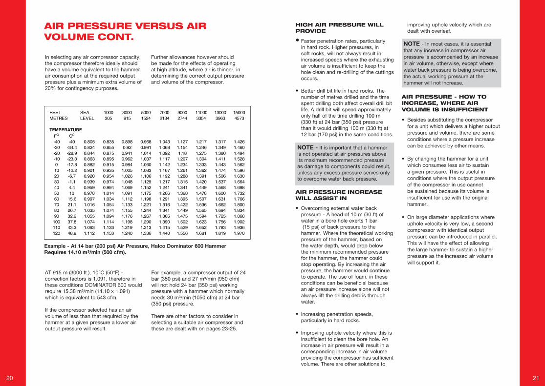
AT 915 m (3000 ft.), 10°C (50°F) - correction factors is 1.091, therefore in these conditions DOMINATOR 600 would require 15.38 m³/min (14.10 x 1.091) which is equivalent to 543 cfm.
If the compressor selected has an air volume of less than that required by the hammer at a given pressure a lower air output pressure will result.
For example, a compressor output of 24 bar (350 psi) and 27 m³/min (950 cfm) will not hold 24 bar (350 psi) working pressure with a hammer which normally needs 30 m³/min (1050 cfm) at 24 bar (350 psi) pressure.
There are other factors to consider in selecting a suitable air compressor and these are dealt with on pages 23-25.
In selecting any air compressor capacity, the compressor therefore ideally should have a volume equivalent to the hammer air consumption at the required output pressure plus a minimum extra volume of 20% for contingency purposes.
Further allowances however should be made for the effects of operating at high altitude, where air is thinner, in determining the correct output pressure and volume of the compressor.
AIR PRESSURE VERSUS AIR VOLUME CONT.
Example - At 14 bar (200 psi) Air Pressure, Halco Dominator 600 Hammer Requires 14.10 m³/min (500 cfm).
HIGH AIR PRESSURE WILL PROVIDE
• Faster penetration rates, particularly in hard rock. Higher pressures, in soft rocks, will not always result in increased speeds where the exhausting air volume is insufficient to keep the hole clean and re-drilling of the cuttings occurs.
• Better drill bit life in hard rocks. The number of metres drilled and the time spent drilling both affect overall drill bit life. A drill bit will spend approximately only half of the time drilling 100 m (330 ft) at 24 bar (350 psi) pressure than it would drilling 100 m (330 ft) at 12 bar (170 psi) in the same conditions.
NOTE - It is important that a hammer is not operated at air pressures above its maximum recommended pressure as damage to components could result, unless any excess pressure serves only to overcome water back pressure.
AIR PRESSURE INCREASE WILL ASSIST IN
• Overcoming external water back pressure - A head of 10 m (30 ft) of water in a bore hole exerts 1 bar (15 psi) of back pressure to the hammer. Where the theoretical working pressure of the hammer, based on the water depth, would drop below the minimum recommended pressure for the hammer, the hammer could stop operating. By increasing the air pressure, the hammer would continue to operate. The use of foam, in these conditions can be beneficial because an air pressure increase alone will not always lift the drilling debris through water.
• Increasing penetration speeds, particularly in hard rocks.
• Improving uphole velocity where this is insufficient to clean the bore hole. An increase in air pressure will result in a corresponding increase in air volume providing the compressor has sufficient volume. There are other solutions to
improving uphole velocity which are dealt with overleaf.
NOTE - In most cases, it is essential that any increase in compressor air pressure is accompanied by an increase in air volume, otherwise, except where water back pressure is being overcome, the actual working pressure at the hammer will not increase.
AIR PRESSURE - HOW TO INCREASE, WHERE AIR VOLUME IS INSUFFICIENT
• Besides substituting the compressor for a unit which delivers a higher output pressure and volume, there are some conditions where a pressure increase can be achieved by other means.
• By changing the hammer for a unit which consumes less air to sustain a given pressure. This is useful in conditions where the output pressure of the compressor in use cannot be sustained because its volume is insufficient for use with the original hammer.
• On large diameter applications where uphole velocity is very low, a second compressor with identical output pressure can be introduced in parallel. This will have the effect of allowing the large hammer to sustain a higher pressure as the increased air volume will support it.
FEET SEA 1000 3000 5000 7000 9000 11000 13000 15000METRES LEVEL 305 915 1524 2134 2744 3354 3963 4573
FO CO
-40 -40 0.805 0.835 0.898 0.968 1.043 1.127 1.217 1.317 1.426-30 -34.4 0.824 0.855 0.92 0.991 1.068 1.154 1.246 1.349 1.460-20 -28.9 0.844 0.875 0.941 1.014 1.092 1.18 1.275 1.380 1.494-10 -23.3 0.863 0.895 0.962 1.037 1.117 1.207 1.304 1.411 1.5280 -17.8 0.882 0.915 0.984 1.060 1.142 1.234 1.333 1.443 1.56210 -12.2 0.901 0.935 1.005 1.083 1.167 1.261 1.362 1.474 1.59620 -6.7 0.920 0.954 1.026 1.106 1.192 1.288 1.391 1.506 1.63030 -1.1 0.939 0.974 1.048 1.129 1.217 1.315 1.420 1.537 1.66440 4.4 0.959 0.994 1.069 1.152 1.241 1.341 1.449 1.568 1.69850 10 0.978 1.014 1.091 1.175 1.266 1.368 1.478 1.600 1.73260 15.6 0.997 1.034 1.112 1.198 1.291 1.395 1.507 1.631 1.76670 21.1 1.016 1.054 1.133 1.221 1.316 1.422 1.536 1.662 1.80080 26.7 1.035 1.074 1.155 1.244 1.341 1.449 1.565 1.694 1.83490 32.2 1.055 1.094 1.176 1.267 1.365 1.475 1.594 1.725 1.868
100 37.8 1.074 1.114 1.198 1.290 1.390 1.502 1.623 1.756 1.902110 43.3 1.093 1.133 1.219 1.313 1.415 1.529 1.652 1.783 1.936120 48.9 1.112 1.153 1.240 1.336 1.440 1.556 1.681 1.819 1.970
TEMPERATURE
22 23
HIGH PRESSURE IS NOT RECOMMENDED WHERE
• The drilling conditions are so soft that the bore hole is being blasted away by the exhausting air.
• The top of the hole is so unstable that it is being destroyed by the high air pressure. It is usual, in these conditions, to temporarily reduce the air pressure until the top of the bore hole is stabilised, after packing, where necessary, the top of the bore hole with clay. This is known as collaring the bore hole.
• The drilling conditions are such that the drilling rate is so fast that the exhausting air cannot clear the drilling debris from the hole resulting in the hammer becoming buried.
• A new hammer is being “run in” during the first hour of operation.
AIR PRESSURE REDUCTIONS - CAUSES
• Unwelcome air pressure reductions or pressure drops can happen in certain conditions resulting in impaired performance. These can be observed by comparing what the compressor’s actual output pressure is to the pressure actually registering on the drill rig’s air pressure gauge. Water in the bore hole exerting back pressure.
• Insufficient compressor volume to sustain the hammer’s required operating pressure.
• Worn or damaged compressor components.
• Where chokes or vents in use have bled so much air volume direct to exhaust that the remaining compressor volume is insufficient to maintain the hammer’s required operating pressure.
• Where chokes or vents are in use because drilling air and choke/vent air exhaust through the same ports. This can lead to back pressure and a drop in air pressure at the hammer.
• Air leaks in the compressed air delivery line and drill pipe joints.
• Hammers which are badly worn internally.
• Voids or fissures in the rocks causing loss of air circulation.
• Operating at high altitudes above sea level where air density is lower.
• Pressure drop to the hammer can occur on air powered drill rigs where the compressed air demands of the rig reduce the compressed air volume available to the hammer to a level which is insufficient to sustain the air pressure.
NOTE - Air pressure at the hammer automatically falls when lifting the hammer to flush
REDUCING AIR PRESSURE INTENTIONALLY
Having accepted that the higher the air pressure, the faster the hammer will drill, in most conditions, there are other priorities to consider which in certain instances are more important than outright penetration rates.
Hole destruction because of excess pressure. Reducing the air pressure may provide a better more useable bore hole.
Excessive wear of the base of hammer where in very abrasive conditions, consumable spares cost replacement is a feature to consider alongside drilling rates.
To prevent a compressor engine working continuously at full speed, which would shorten its service life and increase maintenance costs. A compressor generally runs in a fuel efficient manner at approx. 80% of maximum.
UPHOLE VELOCITY
The exhausting air from a down-the-hole hammer is used as the flushing air to clear the rock cuttings from the bore hole.
To provide an adequate rate for cutting evacuation, an acceptable uphole velocity must be maintained which is 900-1800 m/min. (3000-6000 ft/min).
The actual uphole velocity will be determined by the hole size, drill tube diameter and air consumption of the hammer in use.
The function of a DTH hammer and drill bit is to break the rock and remove the cuttings from the bore hole immediately they are formed. If a hammer fails to fulfil this function because the uphole velocity is insufficient there are several alternatives, although operating conditions may only allow some of these.
Increase the drill tube diameter - On very large hole diameters, shrouded drill tubes, near to the drill bit diameter, may be used. In these conditions a sleeve or shroud can be fitted around the hammer of the same diameter as the drill tubes. The use of upset drill tubes which cause turbulence and a reduction in uphole velocity should be avoided.
DECREASE THE DRILL BIT DIAMETER
Use foam to assist in cutting evacuation from the bore hole. This is explained in detail. Separately.
Increase the Flushing Air Available
This can be done in 3 ways:
1.Intermittently - by simply repeatedly lifting the hammer up from the rock face, the percussion action will cease and extra air, up to twice the normal volume, will pass through the hammer to clean the hole, providing that the compressor has a sufficient reserve of volume.
2.By using a choke or vent in the hammer. Dependent on hammer make, this can either be a plugged orifice in the piston or a bleed facility in the
non return valve, bottom bush or bit retaining rings.
3.By using an air bypass sub adaptor above the hammer. 2 holes angled upwards are machined in the adaptor and these bleed extra air upwards to increase the uphole velocity although this air bypasses the face of the drill bit where it would be most effective.
It is important to ensure that when using air bypass sub adaptors, chokes or vents that the compressor in use has a sufficient reserve of air volume available over and above that needed to sustain its output pressure with the selected hammer, otherwise a pressure reduction will occur in addition to the effect of any back pressure caused by the use of the vent or choke.
The pressure reduction will lead generally to a decrease in penetration speed.

24 25
Where -vm = Velocity in metres per minute.x (m³ ) = m³/min. of air volume passed by the hammer at the selected air pressure.DM² = Diameter of hole - squared (in millimetres).dm² = Diameter of drill tube squared (in millimetres).vf = Velocity in feet per minute.y (cfm) = Volume of cfm of air passed by the hammer at the selected air pressure.DI² = Diameter of hole - squared (in inches)di² = Diameter of drill tube squared (in inches)
UP HOLE VELOCITY
AN ALTERNATIVE METHOD OF CALCULATING UP HOLE VELOCITY IS AS FOLLOWS:A. Establish the volume of air in m³/min. being passed through the hammer.B. Establish the velocity per m³ of air, from chart across, with relevant tube and hole
diameter.C. Multiply A x B = answer in m/minute.D. If Feet per minute required - Multiply m/minute x 3.28 WITH HALCO HAMMERS FOR EXAMPLEDOMINATOR 600 @ 14 bar (200 psi) = 14.10 m³/min AIR CONSUMPTION114 mm (4.1/2”) TUBE/165 mm (6.1/2”) BIT = 89 m/min VELOCITY FOR 1 m³/minUPHOLE VELOCITY = 14.10 x 89 = 1255 m/min HAMMER AIR CONSUMPTION
The chart, below, lists the velocity in metres per minute for each 1 m³ of air passed through the hammer, for each drill tube and drill bit diameter combination.
2 1/8" 2 3/4" 3" 3 1/2" 4" 4 1/2" 5" 5 1/2"54 mm 70 mm 76 mm 89 mm102 mm114 mm127 mm140 mm
2 3/4" 70 mm 6423 1/3" 85 mm 295 548 8803 1/2" 90 mm 254 420 607
3 15/16" 100 mm 180 249 3044 1/8" 105 mm 208 243 4104 1/4" 108 mm 188 218 3404 1/3" 110 mm 177 201 305 7514 1/2" 115 mm 153 171 240 4514 3/4" 120 mm 134 148 196 319 907
5" 127 mm 113 123 155 222 4075 1/8" 130 mm 106 114 142 196 3265 1/2" 140 mm 87 92 109 138 193 367
6" 152 mm 70 73 83 99 125 1796 1/8" 156 mm 66 69 78 92 114 1586 1/4" 159 mm 63 66 74 86 105 1406 1/2" 165 mm 57 59 66 76 89 1156 3/4" 171 mm 52 54 59 67 78 96
7" 178 mm 54 60 69 82 1057 1/2" 191 mm 45 49 55 63 907 7/8" 200 mm 40 43 47 53 62
8" 203 mm 38 41 45 51 588 1/2" 216 mm 33 35 38 42 478 7/8" 225 mm 30 32 34 37 419 5/8" 245 mm 24 26 27 29 32
10" 254 mm 22 24 25 26 2811" 279 mm 18 19 20 21 22
11 7/8" 300 mm 15 16 17 17 1812 1/4" 311 mm 14 15 15 16 16
13" 330 mm 13 14 1414 3/4" 375 mm 10 10 11
15" 381 mm 10 10 1017 1/2" 445 mm 7 7 718 1/2" 470 mm 6 6 6
20" 508 mm 5 5 522" 559 mm 4 4 424" 610 mm 4 4 4
DRILL TUBE DIAMETERDRILL BIT DIA.
Hammer Model7 bar
(100 psi)10.5 bar(150 psi)
12 bar(170 psi)
14 bar(200 psi)
17 bar(250 psi)
24 bar(350 psi)
Dominator 100 1.6 2.6 3.0 3.5 4.5 -Mach 20 2 3.8 4.8 5.8 7.6 -Mach 303 2.8 4.4 5.0 5.9 7.3 10.0Dart 350 2.5 4.7 5.6 7.0 9.3 13.8Dominator 350 2.3 4.4 5.2 6.5 8.5 12.6NT4 4.3 6.5 8.8 11.0 13.2 15.5Mach 44 4.8 7.0 8.0 9.5 12.0 17.2Dominator 400/S-Dominator 400 5.2 7.5 8.5 9.9 12.2 17NT5 / NT5 HD 5.6 9.4 13.2 17.0 20.8 24.6NT5E 6.6 11.2 15.8 20.4 25.0 29.6Mach 50 5.7 7.2 8.2 11.0 14.9 23.4Dominator 500/S-Dominator 500/S-Dominator 550 6.5 8.5 9.9 12. 15.6 22.65NT6/NT6 HD 6.8 10.8 14.8 18.8 22.8 26.8NT6E 8.8 13.5 18.2 22.9 27.5 32.2Dominator 600/S-Dominator 600/S-Dominator 650 - 9.5 12 14.1 19.5 30Mach 60 5.1 7.9 9.1 12.5 16.4 25.5Dominator 750 9.9 15.7 18 21.5 27.3 38.5Dominator 800 6.5 10.8 13.9 15.1 19.3 27.9Dominator 880 10.9 16.6 18.9 22.4 28.1 39.6Dominator 880 DeepWell 14.6 23.5 27.1 32.5 41.5 59.4Dominator 850 11 16.8 19 22.5 28.2 39.6Dominator 1000 15.6 24 32 40.3 48.5 56.6Mach 120 - - 24.35 28.3 35.4 48.1Mach 122/132/142/S-Dominator 1200 19.8 29.45 33.4 39.05 48.1 70.8
THE FORMULA FOR CALCULATING UP HOLE VELOCITY
IS AS FOLLOWS:
METRIC vm = x(m³) x 1,305,096 / DM² - dm²
IMPERIAL vf = y (cfm) x 183.40 / DI² - di²
26 27
EQUIPMENT SELECTION
HAMMER /DRILL BIT /DRILL TUBE AND COMPRESSOR SELECTION
28 29
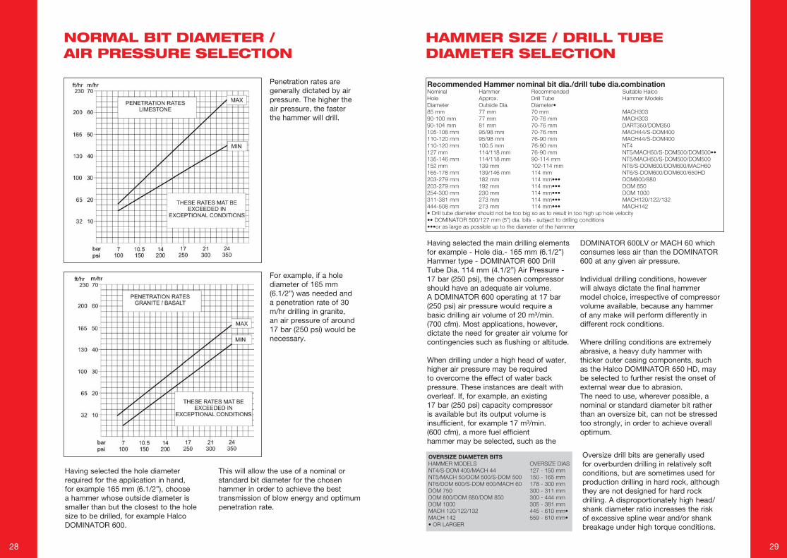
Penetration rates are generally dictated by air pressure. The higher the air pressure, the faster the hammer will drill.
For example, if a hole diameter of 165 mm (6.1/2”) was needed and a penetration rate of 30 m/hr drilling in granite, an air pressure of around 17 bar (250 psi) would be necessary.
Having selected the hole diameter required for the application in hand, for example 165 mm (6.1/2”), choose a hammer whose outside diameter is smaller than but the closest to the hole size to be drilled, for example Halco DOMINATOR 600.
This will allow the use of a nominal or standard bit diameter for the chosen hammer in order to achieve the best transmission of blow energy and optimum penetration rate.
Recommended Hammer nominal bit dia./drill tube dia.combinationNominal Hammer Recommended SuitableHalcoHole Approx. DrillTube HammerModelsDiameter OutsideDia. Diameter•85mm 77mm 70mm MACH30390-100mm 77mm 70-76mm MACH30390-104mm 81mm 70-76mm DART350/DOM350105-108mm 95/98mm 70-76mm MACH44/S-DOM400110-120mm 95/98mm 76-90mm MACH44/S-DOM400110-120mm 100.5mm 76-90mm NT4127mm 114/118mm 76-90mm NT5/MACH50/S-DOM500/DOM500••135-146mm 114/118mm 90-114mm NT5/MACH50/S-DOM500/DOM500152mm 139mm 102-114mm NT6/S-DOM600/DOM600/MACH60165-178mm 139/146mm 114mm NT6/S-DOM600/DOM600/650HD203-279mm 182mm 114mm••• DOM800/880203-279mm 192mm 114mm••• DOM850254-300mm 230mm 114mm••• DOM1000311-381mm 273mm 114mm••• MACH120/122/132444-508mm 273mm 114mm••• MACH142•Drilltubediametershouldnotbetoobigsoastoresultintoohighupholevelocity••DOMINATOR500/127mm(5”)dia.bits-subjecttodrillingconditions•••oraslargeaspossibleuptothediameterofthehammer
Having selected the main drilling elements for example - Hole dia.- 165 mm (6.1/2”) Hammer type - DOMINATOR 600 Drill Tube Dia. 114 mm (4.1/2”) Air Pressure - 17 bar (250 psi), the chosen compressor should have an adequate air volume. A DOMINATOR 600 operating at 17 bar (250 psi) air pressure would require a basic drilling air volume of 20 m³/min. (700 cfm). Most applications, however, dictate the need for greater air volume for contingencies such as flushing or altitude.
When drilling under a high head of water, higher air pressure may be required to overcome the effect of water back pressure. These instances are dealt with overleaf. If, for example, an existing 17 bar (250 psi) capacity compressor is available but its output volume is insufficient, for example 17 m³/min. (600 cfm), a more fuel efficient hammer may be selected, such as the
DOMINATOR 600LV or MACH 60 which consumes less air than the DOMINATOR 600 at any given air pressure.
Individual drilling conditions, however will always dictate the final hammer model choice, irrespective of compressor volume available, because any hammer of any make will perform differently in different rock conditions.
Where drilling conditions are extremely abrasive, a heavy duty hammer with thicker outer casing components, such as the Halco DOMINATOR 650 HD, may be selected to further resist the onset of external wear due to abrasion.The need to use, wherever possible, a nominal or standard diameter bit rather than an oversize bit, can not be stressed too strongly, in order to achieve overall optimum.
OVERSIZE DIAMETER BITSHAMMERMODELS OVERSIZEDIASNT4/S-DOM400/MACH44 127-150mmNT5/MACH50/DOM500/S-DOM500 150-165mmNT6/DOM600/S-DOM600/MACH60 178-300mmDOM750 300-311mmDOM800/DOM880/DOM850 300-444mmDOM1000 305-381mmMACH120/122/132 445-610mm•MACH142 559-610mm••ORLARGER
Oversize drill bits are generally used for overburden drilling in relatively soft conditions, but are sometimes used for production drilling in hard rock, although they are not designed for hard rock drilling. A disproportionately high head/shank diameter ratio increases the risk of excessive spline wear and/or shank breakage under high torque conditions.
NORMAL BIT DIAMETER / AIR PRESSURE SELECTION
HAMMER SIZE / DRILL TUBE DIAMETER SELECTION
30 31
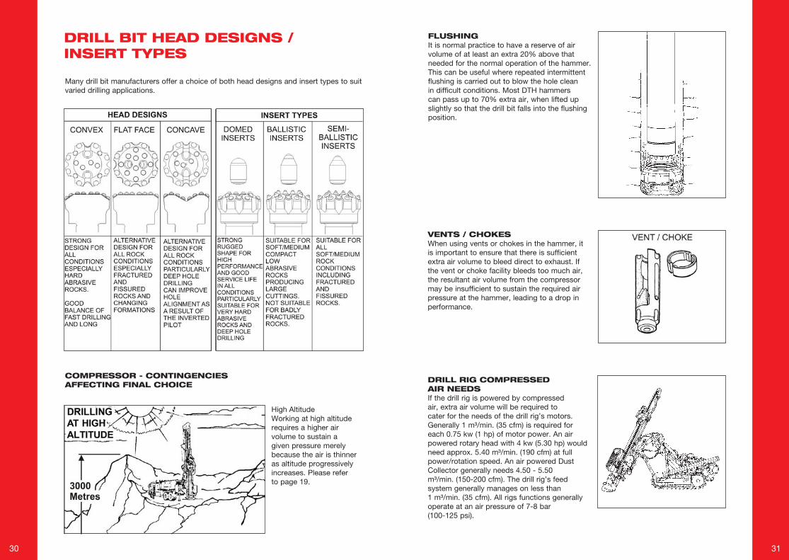
Many drill bit manufacturers offer a choice of both head designs and insert types to suit varied drilling applications.
COMPRESSOR - CONTINGENCIES AFFECTING FINAL CHOICE
High AltitudeWorking at high altitude requires a higher air volume to sustain a given pressure merely because the air is thinner as altitude progressively increases. Please refer to page 19.
FLUSHINGIt is normal practice to have a reserve of airvolume of at least an extra 20% above thatneeded for the normal operation of the hammer. This can be useful where repeated intermittent flushing is carried out to blow the hole clean in difficult conditions. Most DTH hammers can pass up to 70% extra air, when lifted up slightly so that the drill bit falls into the flushing position.
VENTS / CHOKESWhen using vents or chokes in the hammer, it is important to ensure that there is sufficient extra air volume to bleed direct to exhaust. If the vent or choke facility bleeds too much air, the resultant air volume from the compressor may be insufficient to sustain the required air pressure at the hammer, leading to a drop in performance.
DRILL RIG COMPRESSED AIR NEEDSIf the drill rig is powered by compressedair, extra air volume will be required tocater for the needs of the drill rig’s motors. Generally 1 m³/min. (35 cfm) is required for each 0.75 kw (1 hp) of motor power. An air powered rotary head with 4 kw (5.30 hp) would need approx. 5.40 m³/min. (190 cfm) at full power/rotation speed. An air powered Dust Collector generally needs 4.50 - 5.50 m³/min. (150-200 cfm). The drill rig’s feed system generally manages on less than 1 m³/min. (35 cfm). All rigs functions generally operate at an air pressure of 7-8 bar (100-125 psi).
DRILL BIT HEAD DESIGNS / INSERT TYPES
32 33
COMPRESSOR LIFE
To provide an optimum service life for a compressor, it should generally work at only 80% of its full capacity. It may be advisable therefore to select a compressor with a larger pressure capability than that needed in order to increase its service life.
GROUNDWATER IN THE BORE HOLE
Water in the bore hole exerts a back pressure of 1 bar (14.5 psi) for every 10 m (33 ft) of water present.
To sustain therefore an air pressure of 17 bar (250 psi) under 70 m (230 ft) of water a compressor output pressure of 24 bar (350 psi) would be required although the air volume needed would only be that necessary to sustain an air pressure of 17 bar (250 psi).
MULTIPLE COMPRESSORS
On large diameters or deep hole applications, two or more compressors may be connected in tandem feeding into one common airline. It is important to ensure that each compressor is protected by a non return valve and to remember that the resultant combined output pressure will be equal to that of the compressor with the lowest output pressure.
For example -17 m³ @ 12 bar + 17 m³/min. @ 17 bar= 34 m³/min. @ 12 bar(600 cfm @ 170 psi + 600 cfm@ 250 psi = 1200 cfm @ 170 psi)
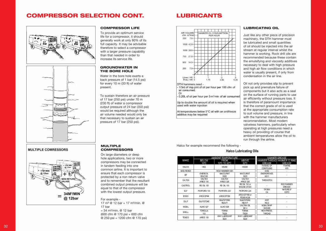
LUBRICATING OIL
Just like any other piece of precision machinery, the DTH hammer must be lubricated and small quantities of oil should be injected into the air stream at regular interval whilst the hammer is working. Rock drill oils are recommended because these contain the emulsifying and viscosity additives necessary to deal with high pressure and high air flow conditions in which water is usually present, if only from condensation in the air line.
Oil not only provides slip to prevent pick up and premature failure of components but it also acts as a seal on the surface of running parts to use air efficiently without pressure loss. It is therefore of paramount importance that the correct grade of oil is used at the appropriate consumption rate to suit volume and pressure, in line with the hammer manufacturers recommendation. Most modern valveless hammers, particularly when operating at high pressures need a heavy oil providing of course that ambient temperatures allow the oil to run through the airline.
Halco for example recommend the following -
COMPRESSOR SELECTION CONT. LUBRICANTS
34 35
FOAMWhere drilling conditions dictate the need, foam should be made available together with a suitable injection pump and water supply.
Details on application/conditions where water/foam injection would be beneficial can be found on pages 49 and 50.
HAMMER LUBRICATORSAn air line lubricator should be available to continually inject oil into the air stream whilst the hammer is operating. Not only should the lubricator be in working order but it should be of a design which will cope with the compressor air pressure, which can be up to 24 bar (350 psi) or even higher.
SERVICE TOOLSTo avoid damage to hammers during servicing, it is advisable to ensure that the correct service tools are available.
HAMMER DISMANTLINGA purpose built hammer stripping bench is adviseable in order to avoid damage to hammers.
HAMMER STRIPPING BENCHACCESSORIES
GRINDING EQUIPMENTIn abrasive conditions, wear to the tungsten carbide buttons can destroy a drill bit after only a very short life. It is adviseable therefore, when drilling in abrasive conditions that suitable grinding equipment is available.
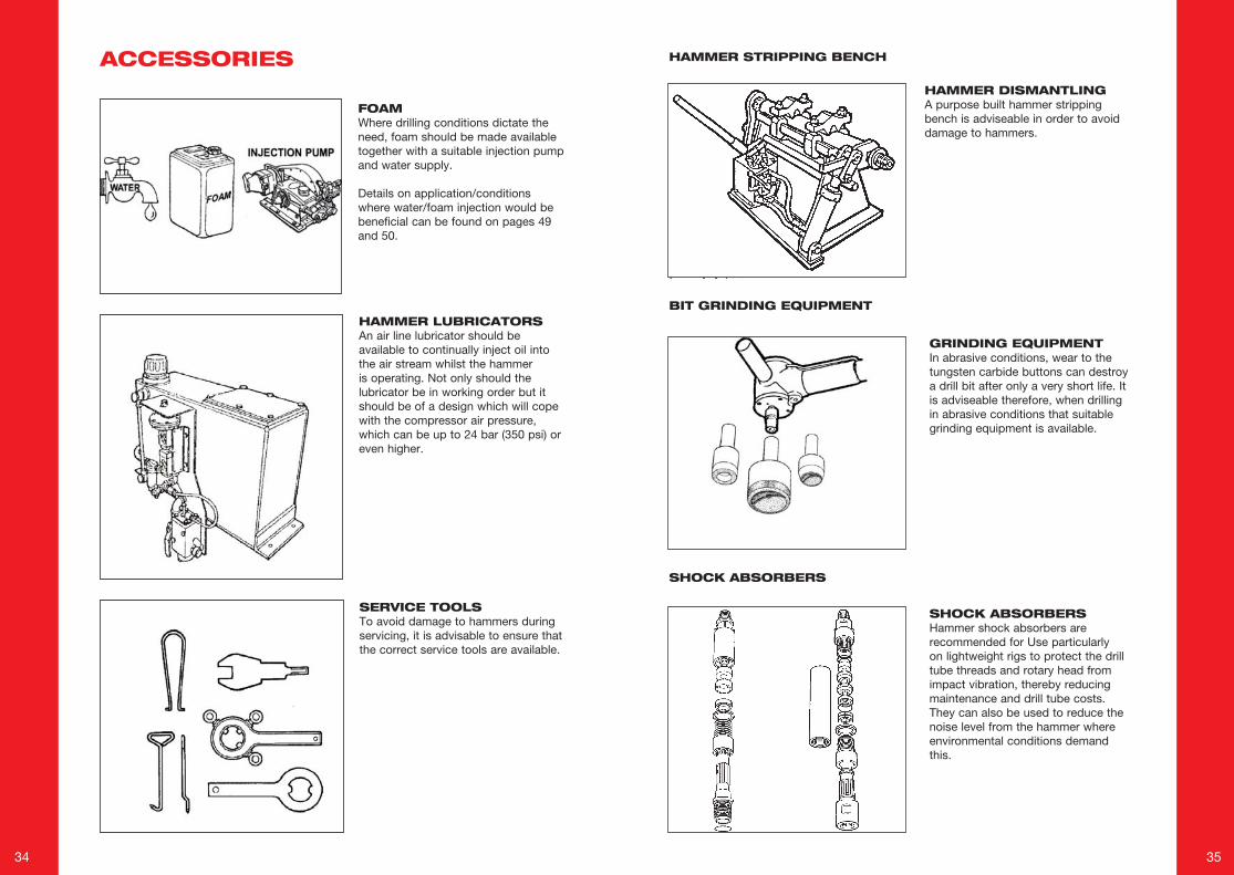
SHOCK ABSORBERSHammer shock absorbers are recommended for Use particularly on lightweight rigs to protect the drill tube threads and rotary head from impact vibration, thereby reducing maintenance and drill tube costs. They can also be used to reduce the noise level from the hammer where environmental conditions demand this.
BIT GRINDING EQUIPMENT
SHOCK ABSORBERS
36 37
OPERATING DTH EQUIPMENT
ROTATION SPEEDS
THRUST
HOLDBACK
TORQUE
DEPTH CAPABILITIES
PENETRATION RATES
TOOL LIFE
COMMISSIONING
OPERATING AND COST SAVING HINTS
38 39
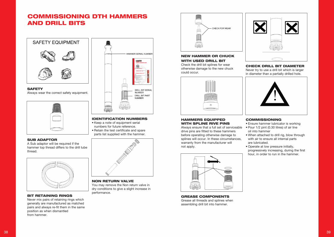
SAFETYAlways wear the correct safety equipment.
SUB ADAPTORA Sub adaptor will be required if the hammer top thread differs to the drill tube thread.
BIT RETAINING RINGSNever mix pairs of retaining rings which generally are manufactured as matched pairs and always re-fit them in the same position as when dismantled from hammer.
IDENTIFICATION NUMBERS• Keep a note of equipment serial
numbers for future reference.• Retain the test certificate and spare
parts list supplied with the hammer.
NON RETURN VALVEYou may remove the Non return valve in dry conditions to give a slight increase in performance.
NEW HAMMER OR CHUCK WITH USED DRILL BITCheck the drill bit splines for wear otherwise damage to the new chuck could occur.
HAMMERS EQUIPPED WITH SPLINE RIVE PINSAlways ensure that a full set of serviceable drive pins are fitted to these hammers before operating otherwise damage to splines will occur. In these circumstances, warranty from the manufacturer will not apply.
GREASE COMPONENTSGrease all threads and splines whenassembling drill bit into hammer.
CHECK DRILL BIT DIAMETERNever try to use a drill bit which is larger in diameter than a partially drilled hole.
COMMISSIONING• Ensure hammer lubricator is working• Pour 1/2 pint (0.30 litres) of air line oil into hammer• When attached to drill rig, blow through
with air to ensure all internal parts are lubricated.
• Operate at low pressure initially, progressively increasing, during the first hour, in order to run in the hammer.
COMMISSIONING DTH HAMMERS AND DRILL BITS
40 41
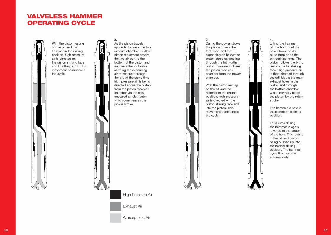
1.With the piston resting on the bit and the hammer in the drilling position, high pressure air is directed on the piston striking face and lifts the piston. This movement commences the cycle.
2.As the piston travels upwards it covers the top exhaust chamber. Further piston movement covers the live air port to the bottom of the piston and uncovers the foot valve allowing the expanding air to exhaust through the bit. At the same time high pressure air is being directed above the piston from the piston reservoir chamber via the now unsealed air distributor which commences the power stroke.
HighPressureAir
ExhaustAir
AtmosphericAir
3.During the power stroke the piston covers the foot valve and the expanding air below the piston stops exhausting through the bit. Further piston movement closes the piston reservoir chamber from the power chamber.
With the piston resting on the bit and the hammer in the drilling position, high pressure air is directed on the piston striking face and lifts the piston. This movement commences the cycle.
4.Lifting the hammer off the bottom of the hole allows the drill bit to drop on to the bit retaining rings. The piston follows the bit to rest on the bit striking face. High pressure air is then directed through the drill bit via the main exhaust holes in the piston and through the bottom chamber which normally feeds the piston for the return stroke.
The hammer is now in the maximum flushing position.
To resume drilling the hammer is again lowered to the bottom of the hole. This results in the bit and piston being pushed up into the normal drilling position. The hammer cycle then resume automatically.
VALVELESS HAMMER OPERATING CYCLE
42 43
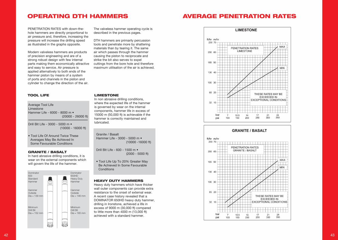
Granite / BasaltHammer Life - 3000 - 5000 m • (10000 -16000 ft)
Drill Bit Life - 600 - 1500 m • (2000 - 5000 ft)
• Tool Life Up To 20% Greater MayBe Achieved In Some FavourableConditions
LIMESTONEIn non abrasive drilling conditions, where the expected life of the hammer is governed by wear on the internal components, hammer life in excess of 15000 m (50,000 ft) is achievable if the hammer is correctly maintained and lubricated.
PENETRATION RATES with down-the-hole hammers are directly proportional to air pressure and, therefore, increasing the pressure will increase the drilling speed as illustrated in the graphs opposite.
Modern valveless hammers are products of precision engineering and are of a strong robust design with few internal parts making them economically attractive and easy to service. Air pressure is applied alternatively to both ends of the hammer piston by means of a system of ports and channels in the piston and cylinder to change the direction of the air.
The valveless hammer operating cycle is described in the previous pages.
DTH hammers are primarily percussion tools and penetrate more by shattering materials than by tearing it. The same air which passes through the hammer causing the piston to reciprocate and strike the bit also serves to expel cuttings from the bore hole and therefore maximum utilisation of the air is achieved.
TOOL LIFE
GRANITE / BASALTIn hard abrasive drilling conditions, it is wear on the external components which will govern the life of the hammer.
HEAVY DUTY HAMMERSHeavy duty hammers which have thicker wall outer components can provide extra resistance to the onset of external wear. A recent case history revealed that a DOMINATOR 650HD heavy duty hammer, drilling in Ironstone, achieved a life in excess of 9000 m (30,000 ft) compared to little more than 4000 m (13,000 ft) achieved with a standard hammer.
Average Tool LifeLimestoneHammer Life - 6000 - 8000 m • (20000 - 26000 ft)
Drill Bit Life - 3000 - 5000 m • (10000 - 16000 ft)
• Tool Life Of Around Twice TheseAverages May Be Achieved InSome Favourable Conditions
Dominator600StandardHammer
Dominator650HDHeavyDutyHammer
HammerOutsideDia=139mm
MinimumDrillBitDia=152mm
HammerOutsideDia=146mm
MinimumDrillBitDia=165mm
AVERAGE PENETRATION RATESOPERATING DTH HAMMERS
44 45
Where drill bit life and cost is the prime consideration on a drill site, rotation speeds should be carefully monitored.
DTH drill bits are rotary - PERCUSSIVE tools with the emphasis on PERCUSSIVE. Their function is to fracture the material being drilled which should then be immediately carried away by the exhaust air. Button bits have no cutting or tearing action as such and the effect of rapid rotation can be prejudicial rather than beneficial to the life of the bit, especially in abrasive rock which wears away fast moving peripheral inserts or in solid dense material which causes the peripheral inserts to overheat and spall due to friction.
If the string is rotated too slowly, this will cause the buttons to impact previously chipped areas of the hole with a resultant drop in penetration speed.
As a general guide - the harder the rock or the larger the bit diameter - the slower the rotation speed required.
It may be necessary however to increase the rotation speed where the rock is badly fissured in order to prevent stalling.
It should be remembered however that stalling in the bore hole could be the result of a very badly worn bit and increasing the rotation speed in these circumstances will only accelerate the problem.
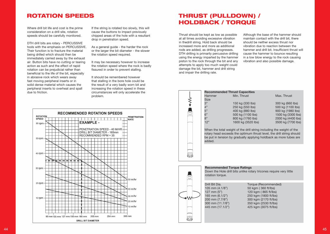
Thrust should be kept as low as possible at all times avoiding excessive vibration in thedrill string. Hold back should be increased more and more as additional rods are added, as drilling progresses. DTH drilling is primarily percussive drilling using the energy imparted by the hammer piston to the rock through the bit and any attempts to apply too much weight could damage the bit, hammer and drill string and impair the drilling rate.
Although the base of the hammer should maintain contact with the drill bit, there should be neither excess thrust nor vibration due to reaction between the hammer and drill bit. Insufficient thrust will cause the hammer to bounce resulting in a low blow energy to the rock causing vibration and also possible damage.
Recommended Thrust CapacitiesHammer Min. Thrust Max. ThrustSize3” 150 kg (330 lbs) 300 kg (660 lbs)4” 250 kg (550 lbs) 500 kg (1100 lbs)5” 400 kg (880 lbs) 900 kg (1980 lbs)6” 500 kg (1100 lbs) 1500 kg (3300 lbs)8” 800 kg (1760 lbs) 2000 kg (4400 lbs)12” 1600 kg (3520 lbs) 3500 kg (7700 lbs)
When the total weight of the drill string including the weight of the rotary head exceeds the optimum thrust level, the drill string should be put in tension by gradually applying holdback as more tubes are added.
Recommended Torque RatingsDown the Hole drill bits unlike rotary tricones require very little rotation torque.
Drill Bit Dia. Torque (Recommended)105 mm (4.1/8”) 50 kgm ( 360 ft/lbs)127 mm (5”) 120 kgm ( 865 ft/lbs)165 mm (6.1/2”) 250 kgm (1800 ft/lbs)200 mm (7.7/8”) 300 kgm (2170 ft/lbs)300 mm (11.7/8”) 350 kgm (2530 ft/lbs)445 mm (17.1/2”) 425 kgm (3075 ft/lbs)
ROTATION SPEEDS THRUST (PULLDOWN) / HOLDBACK / TORQUE
46 47
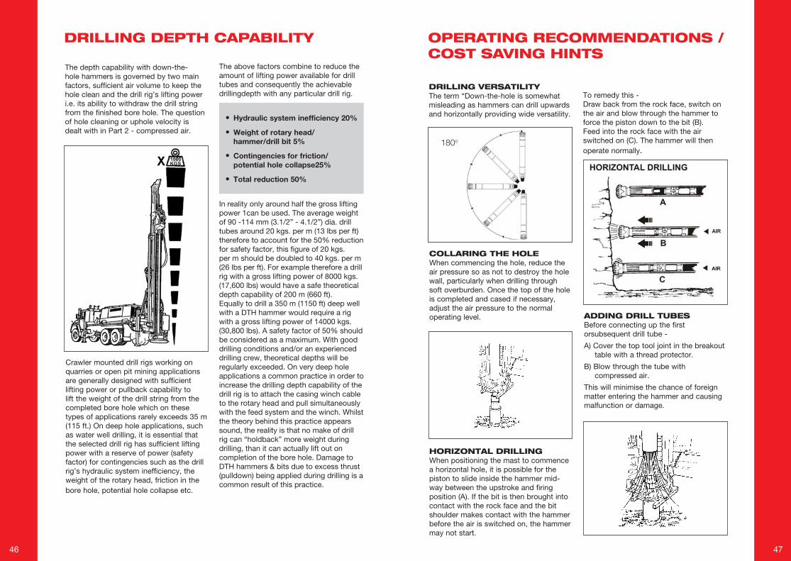
The depth capability with down-the-hole hammers is governed by two main factors, sufficient air volume to keep the hole clean and the drill rig’s lifting power i.e. its ability to withdraw the drill string from the finished bore hole. The question of hole cleaning or uphole velocity is dealt with in Part 2 - compressed air.
Crawler mounted drill rigs working on quarries or open pit mining applications are generally designed with sufficient lifting power or pullback capability to lift the weight of the drill string from the completed bore hole which on these types of applications rarely exceeds 35 m (115 ft.) On deep hole applications, such as water well drilling, it is essential that the selected drill rig has sufficient lifting power with a reserve of power (safety factor) for contingencies such as the drill rig’s hydraulic system inefficiency, the weight of the rotary head, friction in the bore hole, potential hole collapse etc.
In reality only around half the gross lifting power 1can be used. The average weight of 90 -114 mm (3.1/2” - 4.1/2”) dia. drill tubes around 20 kgs. per m (13 lbs per ft) therefore to account for the 50% reduction for safety factor, this figure of 20 kgs. per m should be doubled to 40 kgs. per m (26 lbs per ft). For example therefore a drill rig with a gross lifting power of 8000 kgs. (17,600 lbs) would have a safe theoretical depth capability of 200 m (660 ft). Equally to drill a 350 m (1150 ft) deep well with a DTH hammer would require a rig with a gross lifting power of 14000 kgs. (30,800 lbs). A safety factor of 50% should be considered as a maximum. With good drilling conditions and/or an experienced drilling crew, theoretical depths will be regularly exceeded. On very deep hole applications a common practice in order to increase the drilling depth capability of the drill rig is to attach the casing winch cable to the rotary head and pull simultaneously with the feed system and the winch. Whilst the theory behind this practice appears sound, the reality is that no make of drill rig can “holdback” more weight during drilling, than it can actually lift out on completion of the bore hole. Damage to DTH hammers & bits due to excess thrust (pulldown) being applied during drilling is a common result of this practice.
• Hydraulic system inefficiency 20%
• Weight of rotary head/ hammer/drill bit 5%
• Contingencies for friction/ potential hole collapse25%
• Total reduction 50%
The above factors combine to reduce the amount of lifting power available for drill tubes and consequently the achievable drillingdepth with any particular drill rig.
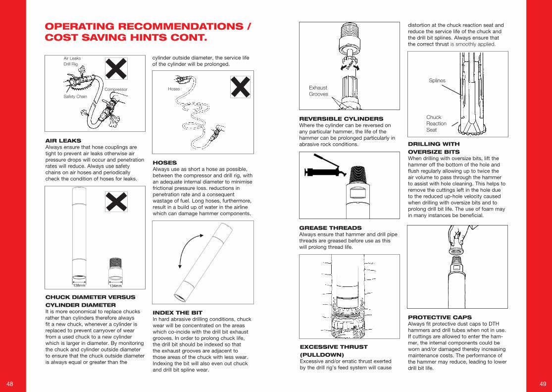
DRILLING VERSATILITYThe term “Down-the-hole is somewhatmisleading as hammers can drill upwardsand horizontally providing wide versatility.
180o
HORIZONTAL DRILLINGWhen positioning the mast to commence a horizontal hole, it is possible for the piston to slide inside the hammer mid-way between the upstroke and firing position (A). If the bit is then brought into contact with the rock face and the bit shoulder makes contact with the hammer before the air is switched on, the hammer may not start.
COLLARING THE HOLEWhen commencing the hole, reduce the air pressure so as not to destroy the hole wall, particularly when drilling through soft overburden. Once the top of the hole is completed and cased if necessary, adjust the air pressure to the normal operating level. ADDING DRILL TUBES
Before connecting up the first orsubsequent drill tube -
A) Cover the top tool joint in the breakout table with a thread protector.
B) Blow through the tube with compressed air.
This will minimise the chance of foreign matter entering the hammer and causing malfunction or damage.
To remedy this -Draw back from the rock face, switch on the air and blow through the hammer to force the piston down to the bit (B).Feed into the rock face with the air switched on (C). The hammer will then operate normally.
DRILLING DEPTH CAPABILITY OPERATING RECOMMENDATIONS / COST SAVING HINTS
48 49
REVERSIBLE CYLINDERSWhere the cylinder can be reversed on any particular hammer, the life of the hammer can be prolonged particularly in abrasive rock conditions.
GREASE THREADSAlways ensure that hammer and drill pipe threads are greased before use as this will prolong thread life.
DRILLING WITH OVERSIZE BITSWhen drilling with oversize bits, lift the hammer off the bottom of the hole and flush regularly allowing up to twice the air volume to pass through the hammer to assist with hole cleaning. This helps to remove the cuttings left in the hole due to the reduced up-hole velocity caused when drilling with oversize bits and to prolong drill bit life. The use of foam may in many instances be beneficial.
PROTECTIVE CAPSAlways fit protective dust caps to DTH hammers and drill tubes when not in use. If cuttings are allowed to enter the ham-mer, the internal components could be worn and/or damaged thereby increasing maintenance costs. The performance of the hammer may reduce, leading to lower drill bit life.
OPERATING RECOMMENDATIONS / COST SAVING HINTS CONT.
AIR LEAKSAlways ensure that hose couplings are tight to prevent air leaks otherwise air pressure drops will occur and penetration rates will reduce. Always use safety chains on air hoses and periodically check the condition of hoses for leaks.
HOSESAlways use as short a hose as possible, between the compressor and drill rig, with an adequate internal diameter to minimise frictional pressure loss. reductions in penetration rate and a consequent wastage of fuel. Long hoses, furthermore, result in a build up of water in the airline which can damage hammer components.
CHUCK DIAMETER VERSUS CYLINDER DIAMETERIt is more economical to replace chucks rather than cylinders therefore always fit a new chuck, whenever a cylinder is replaced to prevent carryover of wear from a used chuck to a new cylinder which is larger in diameter. By monitoring the chuck and cylinder outside diameter to ensure that the chuck outside diameter is always equal or greater than the
Compressor
AirLeaksDrillRig
SafetyChain
Hoses
INDEX THE BITIn hard abrasive drilling conditions, chuck wear will be concentrated on the areas which co-incide with the drill bit exhaust grooves. In order to prolong chuck life, the drill bit should be indexed so that the exhaust grooves are adjacent to those areas of the chuck with less wear. Indexing the bit will also even out chuck and drill bit spline wear.
cylinder outside diameter, the service life of the cylinder will be prolonged.
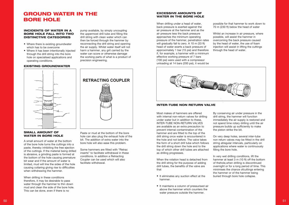
ExhaustGrooves
Splines
ChuckReactionSeat
EXCESSIVE THRUST (PULLDOWN)Excessive and/or erratic thrust exerted by the drill rig’s feed system will cause
distortion at the chuck reaction seat and reduce the service life of the chuck and the drill bit splines. Always ensure that the correct thrust issmoothlyapplied.
50 51
INCIDENTS OF WATER IN A BORE HOLE FALL INTO TWO DISTINCTIVE CATEGORIES
• Where there is existing groundwater which has to be overcome
• Where it has been intentionally injected through the drill string into the bore hole on specialised applications and operating conditions.
EXISTING GROUNDWATER
SMALL AMOUNT OF WATER IN BORE HOLE
A small amount of water at the bottom of the bore hole turns the cuttings into a paste, thereby inhibiting the free ejection of the cuttings. If the material being drilled is abrasive, a grinding paste is formed at the bottom of the hole causing premature bit wear and if the amount of water is limited, mud will line the sides of the hole causing collaring giving rise to difficulties when withdrawing the hammer.
When drilling in these conditions therefore, it may be desirable to pass water through the hammer to thin down mud and clean the side of the bore hole. This can be done, even if there is no
pump available, by simply uncoupling the uppermost drill tube and filling the drill string with clean water which can then be forced through the hammer by reconnecting the drill string and opening the air supply. Whilst water itself will not harm a hammer, any grit carried by the water can score or otherwise damage the working parts of what is a product of precision engineering.
Paste or mud at the bottom of the bore hole can also plug the exhaust hole of the bit. The addition of extra water into the bore hole will also ease this problem.
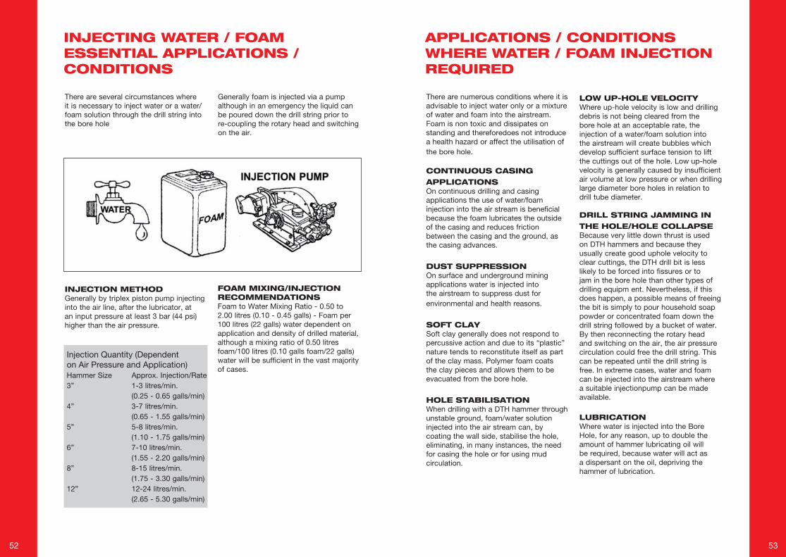
Some hammers are fitted with “Retrac inserts” to facilitate withdrawal in these conditions. In addition a Retracting Coupler can be used which will also facilitate withdrawal.
EXCESSIVE AMOUNTS OF WATER IN THE BORE HOLE
When drilling under a head of water, back pressure is exerted against the air pressure at the hammer and as the air pressure less the back pressure approaches the minimum operating pressure of the hammer, penetration rates will gradually fall to zero. A 10 m (33 ft) head of water exerts a back pressure of approximately 1 bar (15 psi) and therefore if, for example, a hammer with a minimum effective working pressure of 7 bars (100 psi) were used with a compressor unloading at 14 bars (200 psi), it would be
possible for that hammer to work down to 70 m (230 ft) below the head of water
Whilst an increase in air pressure, where possible, will assist the hammer in overcoming the back pressure caused by the head of water, the use of foam injection will assist in lifting the cuttings through the head of water.
INTER-TUBE NON RETURN VALVE
GROUND WATER IN THE BORE HOLE
Most makes of hammers are offered with internal non-return valves for drilling under water but in addition to these, INTER-TUBE NON-RETURN VALVES are available as an extra precaution to prevent internal contamination of the hammer and are fitted to the top of the drill string once water is encountered in the hole and not before. The valve takes the form of a short drill tube which follows the drill string down the hole and to the top of which other drill tubes are attached as drilling progresses.
When the rotation head is detached from the drill string for the purpose of adding drill tubes, the benefits of the valve are that
• It eliminates any suction effect at the hammer.
• It maintains a column of pressurised air above the hammer which counters the water pressure outside the hammer.
By conserving air under pressure in the drill string, the hammer will function immediately the air supply is restored and not spend time rotary drilling until the air pressure builds up sufficiently to make the piston strike the bit.
On very deep holes, several inter-tube non return valves may be fitted in the drill string atregular intervals, particularly on applications where water is continuously filling the bore hole.
In very wet drilling conditions, lift the hammer at least 3 m (10 ft) off the bottom of thehole,when drilling is discontinued overnight or for a long period of time. This minimises the chance ofcuttings entering the hammer or of the hammer being buried through bore hole collapse.
52 53
There are several circumstances where it is necessary to inject water or a water/foam solution through the drill string into the bore hole
Generally foam is injected via a pump although in an emergency the liquid can be poured down the drill string prior to re-coupling the rotary head and switching on the air.
INJECTION METHODGenerally by triplex piston pump injecting into the air line, after the lubricator, at an input pressure at least 3 bar (44 psi) higher than the air pressure.
INJECTING WATER / FOAM ESSENTIAL APPLICATIONS / CONDITIONS
Injection Quantity (Dependent on Air Pressure and Application)Hammer Size Approx. Injection/Rate3” 1-3 litres/min. (0.25 - 0.65 galls/min)4” 3-7 litres/min. (0.65 - 1.55 galls/min)5” 5-8 litres/min. (1.10 - 1.75 galls/min)6” 7-10 litres/min. (1.55 - 2.20 galls/min)8” 8-15 litres/min. (1.75 - 3.30 galls/min)12” 12-24 litres/min. (2.65 - 5.30 galls/min)
FOAM MIXING/INJECTION RECOMMENDATIONSFoam to Water Mixing Ratio - 0.50 to 2.00 litres (0.10 - 0.45 galls) - Foam per 100 litres (22 galls) water dependent on application and density of drilled material, although a mixing ratio of 0.50 litres foam/100 litres (0.10 galls foam/22 galls) water will be sufficient in the vast majority of cases.
There are numerous conditions where it is advisable to inject water only or a mixture of water and foam into the airstream. Foam is non toxic and dissipates on standing and thereforedoes not introduce a health hazard or affect the utilisation of the bore hole.
CONTINUOUS CASING APPLICATIONSOn continuous drilling and casing applications the use of water/foam injection into the air stream is beneficial because the foam lubricates the outside of the casing and reduces friction between the casing and the ground, as the casing advances.
DUST SUPPRESSIONOn surface and underground mining applications water is injected into the airstream to suppress dust for environmental and health reasons.
SOFT CLAYSoft clay generally does not respond to percussive action and due to its “plastic” nature tends to reconstitute itself as part of the clay mass. Polymer foam coats the clay pieces and allows them to be evacuated from the bore hole.
HOLE STABILISATIONWhen drilling with a DTH hammer through unstable ground, foam/water solution injected into the air stream can, by coating the wall side, stabilise the hole, eliminating, in many instances, the need for casing the hole or for using mud circulation.
LOW UP-HOLE VELOCITYWhere up-hole velocity is low and drilling debris is not being cleared from the bore hole at an acceptable rate, the injection of a water/foam solution into the airstream will create bubbles which develop sufficient surface tension to lift the cuttings out of the hole. Low up-hole velocity is generally caused by insufficient air volume at low pressure or when drilling large diameter bore holes in relation to drill tube diameter.
DRILL STRING JAMMING IN THE HOLE/HOLE COLLAPSEBecause very little down thrust is used on DTH hammers and because they usually create good uphole velocity to clear cuttings, the DTH drill bit is less likely to be forced into fissures or to jam in the bore hole than other types of drilling equipm ent. Nevertheless, if this does happen, a possible means of freeing the bit is simply to pour household soap powder or concentrated foam down the drill string followed by a bucket of water. By then reconnecting the rotary head and switching on the air, the air pressure circulation could free the drill string. This can be repeated until the drill string is free. In extreme cases, water and foam can be injected into the airstream where a suitable injectionpump can be made available.
LUBRICATIONWhere water is injected into the Bore Hole, for any reason, up to double the amount of hammer lubricating oil will be required, because water will act as a dispersant on the oil, depriving the hammer of lubrication.
APPLICATIONS / CONDITIONS WHERE WATER / FOAM INJECTION REQUIRED
54 55
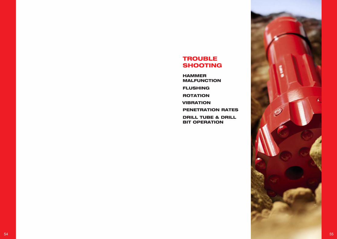
TROUBLESHOOTING
HAMMER MALFUNCTION
FLUSHING
ROTATION
VIBRATION
PENETRATION RATES
DRILL TUBE & DRILL BIT OPERATION
56 57
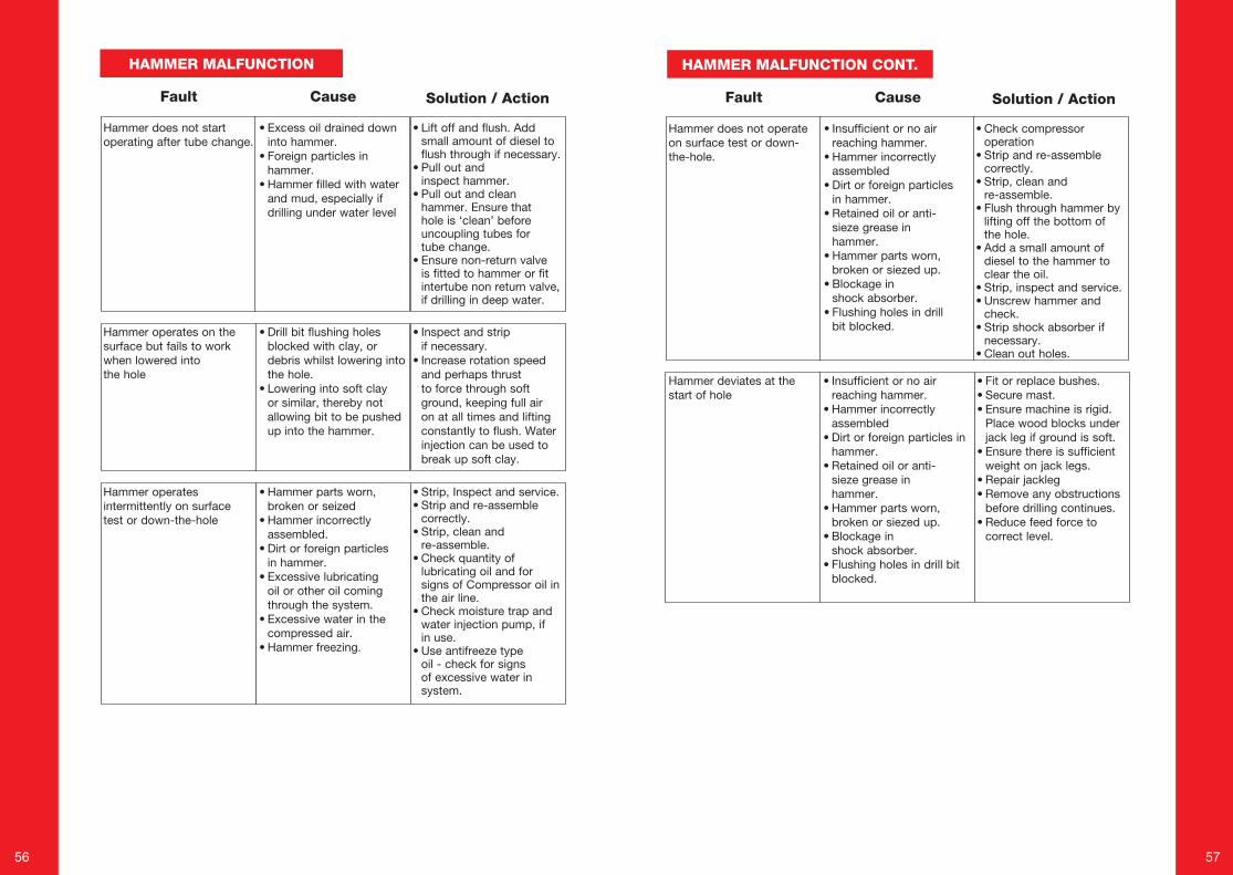
HAMMER MALFUNCTION
Cause Solution / ActionFault
Hammer does not start operating after tube change.
• Excess oil drained down into hammer.
• Foreign particles in hammer.
• Hammer filled with water and mud, especially if drilling under water level
• Lift off and flush. Add small amount of diesel to flush through if necessary.
• Pull out and inspect hammer.
• Pull out and clean hammer. Ensure that hole is ‘clean’ before uncoupling tubes for tube change.
• Ensure non-return valve is fitted to hammer or fit intertube non return valve, if drilling in deep water.
• Inspect and strip if necessary.
• Increase rotation speed and perhaps thrust to force through soft ground, keeping full air on at all times and lifting constantly to flush. Water injection can be used to break up soft clay.
Hammer operates on the surface but fails to work when lowered into the hole
• Drill bit flushing holes blocked with clay, or debris whilst lowering into the hole.
• Lowering into soft clay or similar, thereby not allowing bit to be pushed up into the hammer.
Hammer operates intermittently on surface test or down-the-hole
• Hammer parts worn, broken or seized
• Hammer incorrectly assembled.
• Dirt or foreign particles in hammer.
• Excessive lubricating oil or other oil coming through the system.
• Excessive water in the compressed air.
• Hammer freezing.
• Strip, Inspect and service.• Strip and re-assemble
correctly.• Strip, clean and
re-assemble.• Check quantity of
lubricating oil and for signs of Compressor oil in the air line.
• Check moisture trap and water injection pump, if in use.
• Use antifreeze type oil - check for signs of excessive water in system.
HAMMER MALFUNCTION CONT.
Cause Solution / ActionFault
Hammer does not operate on surface test or down-the-hole.
• Insufficient or no air reaching hammer.
• Hammer incorrectly assembled
• Dirt or foreign particles in hammer.
• Retained oil or anti-sieze grease in hammer.
• Hammer parts worn, broken or siezed up.
• Blockage in shock absorber.
• Flushing holes in drill bit blocked.
• Check compressor operation
• Strip and re-assemble correctly.
• Strip, clean and re-assemble.
• Flush through hammer by lifting off the bottom of the hole.
• Add a small amount of diesel to the hammer to clear the oil.
• Strip, inspect and service.• Unscrew hammer and
check. • Strip shock absorber if
necessary.• Clean out holes.
• Fit or replace bushes.• Secure mast.• Ensure machine is rigid.
Place wood blocks under jack leg if ground is soft.
• Ensure there is sufficient weight on jack legs.
• Repair jackleg• Remove any obstructions
before drilling continues.• Reduce feed force to
correct level.
Hammer deviates at the start of hole
• Insufficient or no air reaching hammer.
• Hammer incorrectly assembled
• Dirt or foreign particles in hammer.
• Retained oil or anti-sieze grease in hammer.
• Hammer parts worn, broken or siezed up.
• Blockage in shock absorber.
• Flushing holes in drill bit blocked.
58 59
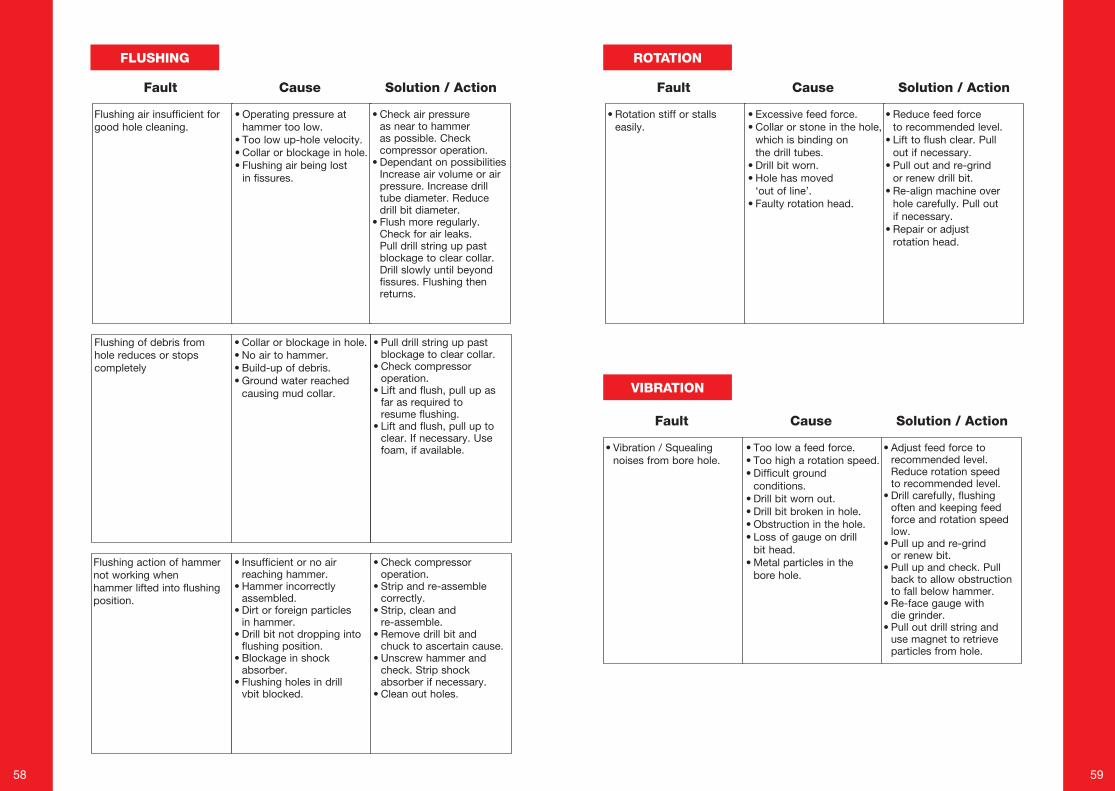
FLUSHING ROTATION
VIBRATION
Cause Solution / ActionFault
Flushing air insufficient for good hole cleaning.
• Operating pressure at hammer too low.
• Too low up-hole velocity. • Collar or blockage in hole.• Flushing air being lost
in fissures.
• Check air pressure as near to hammer as possible. Check compressor operation.
• Dependant on possibilities Increase air volume or air pressure. Increase drill tube diameter. Reduce drill bit diameter.
• Flush more regularly. Check for air leaks. Pull drill string up past blockage to clear collar. Drill slowly until beyond fissures. Flushing then returns.
• Pull drill string up past blockage to clear collar.
• Check compressor operation.
• Lift and flush, pull up as far as required to resume flushing.
• Lift and flush, pull up to clear. If necessary. Use foam, if available.
Flushing of debris from hole reduces or stops completely
• Collar or blockage in hole. • No air to hammer. • Build-up of debris.• Ground water reached
causing mud collar.
Flushing action of hammer not working when hammer lifted into flushing position.
• Insufficient or no air reaching hammer.
• Hammer incorrectly assembled.
• Dirt or foreign particles in hammer.
• Drill bit not dropping into flushing position.
• Blockage in shock absorber.
• Flushing holes in drill vbit blocked.
• Check compressor operation.
• Strip and re-assemble correctly.
• Strip, clean and re-assemble.
• Remove drill bit and chuck to ascertain cause.
• Unscrew hammer and check. Strip shock absorber if necessary.
• Clean out holes.
Cause Solution / ActionFault
• Rotation stiff or stalls easily.
• Excessive feed force. • Collar or stone in the hole,
which is binding on the drill tubes.
• Drill bit worn. • Hole has moved
‘out of line’. • Faulty rotation head.
• Reduce feed force to recommended level.
• Lift to flush clear. Pull out if necessary.
• Pull out and re-grind or renew drill bit.
• Re-align machine over hole carefully. Pull out if necessary.
• Repair or adjust rotation head.
Cause Solution / ActionFault
• Vibration / Squealing noises from bore hole.
• Too low a feed force. • Too high a rotation speed. • Difficult ground
conditions.• Drill bit worn out.• Drill bit broken in hole.• Obstruction in the hole. • Loss of gauge on drill
bit head. • Metal particles in the
bore hole.
• Adjust feed force to recommended level. Reduce rotation speed to recommended level.
• Drill carefully, flushing often and keeping feed force and rotation speed low.
• Pull up and re-grind or renew bit.
• Pull up and check. Pull back to allow obstruction to fall below hammer.
• Re-face gauge with die grinder.
• Pull out drill string and use magnet to retrieve particles from hole.
60 61
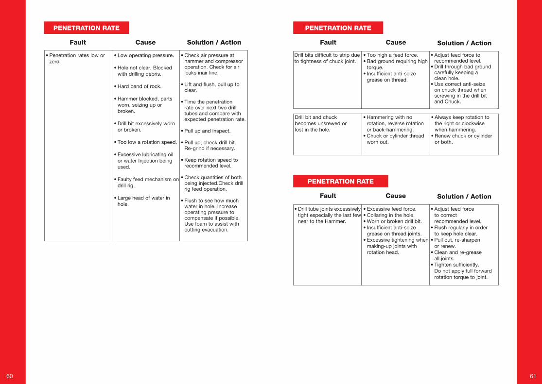
PENETRATION RATE PENETRATION RATE
Cause Solution / ActionFault
• Penetration rates low or zero
• Low operating pressure.
• Hole not clear. Blocked with drilling debris.
• Hard band of rock.
• Hammer blocked, parts worn, seizing up or broken.
• Drill bit excessively worn or broken.
• Too low a rotation speed.
• Excessive lubricating oil or water Injection being used.
• Faulty feed mechanism on drill rig.
• Large head of water in hole.
• Check air pressure at hammer and compressor operation. Check for air leaks inair line.
• Lift and flush, pull up to clear.
• Time the penetration rate over next two drill tubes and compare with expected penetration rate.
• Pull up and inspect.
• Pull up, check drill bit. Re-grind if necessary.
• Keep rotation speed to recommended level.
• Check quantities of both being injected.Check drill rig feed operation.
• Flush to see how much water in hole. Increase operating pressure to compensate if possible. Use foam to assist with cutting evacuation.
Cause Solution / ActionFault
Drill bits difficult to strip due to tightness of chuck joint.
• Too high a feed force.• Bad ground requiring high
torque.• Insufficient anti-seize
grease on thread.
• Adjust feed force to recommended level.
• Drill through bad ground carefully keeping a clean hole.
• Use correct anti-seize on chuck thread when screwing in the drill bit and Chuck.
• Always keep rotation to the right or clockwise when hammering.
• Renew chuck or cylinder or both.
Drill bit and chuck becomes unsrewed or lost in the hole.
• Hammering with no rotation, reverse rotation or back-hammering.
• Chuck or cylinder thread worn out.
PENETRATION RATE
Cause Solution / ActionFault
• Drill tube joints excessively tight especially the last few near to the Hammer.
• Excessive feed force. • Collaring in the hole. • Worn or broken drill bit.• Insufficient anti-seize
grease on thread joints.• Excessive tightening when
making-up joints with rotation head.
• Adjust feed force to correct recommended level.
• Flush regularly in order to keep hole clear.
• Pull out, re-sharpen or renew.
• Clean and re-grease all joints.
• Tighten sufficiently. Do not apply full forward rotation torque to joint.
62 63
DRILL BIT CARE
DRILL BIT HANDLING
INSPECTION
RE-GRINDING
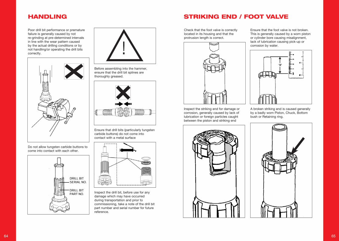
64 65
Poor drill bit performance or premature failure is generally caused by not re-grinding at pre-determined intervals in line with the wear pattern caused by the actual drilling conditions or by not handling/or operating the drill bits correctly. !
Ensure that drill bits (particularly tungsten carbide buttons) do not come into contact with a metal surface
Do not allow tungsten carbide buttons to come into contact with each other.
Inspect the drill bit, before use for any damage which may have occurred during transportation and prior to commissioning, take a note of the drill bit part number and serial number for future reference.
Before assembling into the hammer, ensure that the drill bit splines are thoroughly greased.
Check that the foot valve is correctly located in its housing and that the protrusion length is correct.
Ensure that the foot valve is not broken. This is generally caused by a worn piston or cylinder bore causing misalignment, lack of lubrication causing pick-up or corrosion by water.
Inspect the striking end for damage or corrosion, generally caused by lack of lubrication or foreign particles caught between the piston and striking end
A broken striking end is caused generally by a badly worn Piston, Chuck, Bottom bush or Retaining ring.
HANDLING STRIKING END / FOOT VALVE
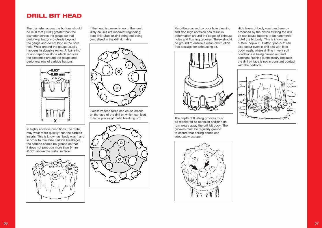
66 67
The depth of flushing grooves must be monitored as abrasion and/or high rpm wears away the drill bit body. The grooves must be regularly ground to ensure that drilling debris can adequately escape.
Re-drilling caused by poor hole cleaning and also high abrasion can result in deformation around the edges of exhaust holes and flushing grooves. These should be ground to ensure a clean obstruction free passage for exhausting air.
High levels of body wash and energyproduced by the piston striking the drillbit can cause buttons to be hammered outof the bit body. This is known as button ‘pop-out’. Button ‘pop-out’ can also occur even in drill bits with little body wash, where drilling in very soft conditions is being carried out and constant flushing is necessary because the drill bit face is not in constant contact with the bedrock.
The diameter across the buttons should be 0.80 mm (0.03”) greater than the diameter across the gauge so that peripheral buttons protrude beyond the gauge and do not bind in the bore hole. Wear around the gauge usually happens in abrasive rocks. A ‘barreling’ or anti-taper develops which reduces the clearance around the gauge and peripheral row of carbide buttons.
In highly abrasive conditions, the metal may wear more quickly than the carbide inserts. This is known as ‘body wash’ and in order to minimise carbide breakages, the carbide should be ground so that it does not protrude more than 9 mm (0.35”) above the metal surface.
If the head is unevenly worn, the most likely causes are incorrect regrinding, bent drill tubes or drill string not being centralised in the drill rig table
Excessive feed force can cause cracks on the face of the drill bit which can lead to large pieces of metal breaking off.
DRILL BIT HEAD
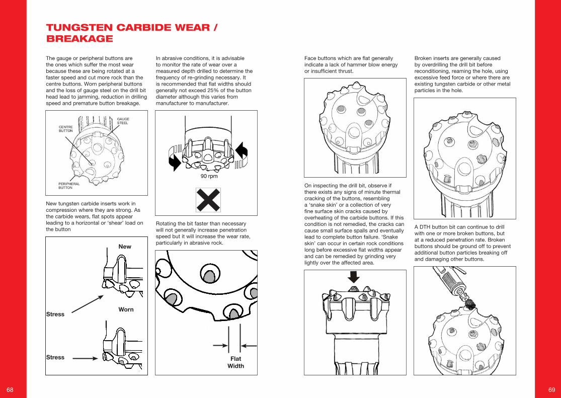
68 69
Face buttons which are flat generally indicate a lack of hammer blow energy or insufficient thrust.
On inspecting the drill bit, observe if there exists any signs of minute thermal cracking of the buttons, resembling a ‘snake skin’ or a collection of very fine surface skin cracks caused by overheating of the carbide buttons. If this condition is not remedied, the cracks can cause small surface spalls and eventually lead to complete button failure. ‘Snake skin’ can occur in certain rock conditions long before excessive flat widths appear and can be remedied by grinding very lightly over the affected area.
Broken inserts are generally caused by overdrilling the drill bit before reconditioning, reaming the hole, using excessive feed force or where there are existing tungsten carbide or other metal particles in the hole.
A DTH button bit can continue to drill with one or more broken buttons, but at a reduced penetration rate. Broken buttons should be ground off to prevent additional button particles breaking off and damaging other buttons.
The gauge or peripheral buttons are the ones which suffer the most wear because these are being rotated at a faster speed and cut more rock than the centre buttons. Worn peripheral buttons and the loss of gauge steel on the drill bit head lead to jamming, reduction in drilling speed and premature button breakage.
New tungsten carbide inserts work in compression where they are strong. As the carbide wears, flat spots appear leading to a horizontal or ‘shear’ load on the button
Rotating the bit faster than necessary will not generally increase penetration speed but it will increase the wear rate, particularly in abrasive rock.
In abrasive conditions, it is advisable to monitor the rate of wear over a measured depth drilled to determine the frequency of re-grinding necessary. It is recommended that flat widths should generally not exceed 25% of the button diameter although this varies from manufacturer to manufacturer.
TUNGSTEN CARBIDE WEAR / BREAKAGE
WornStress
Stress
New
Flat Width
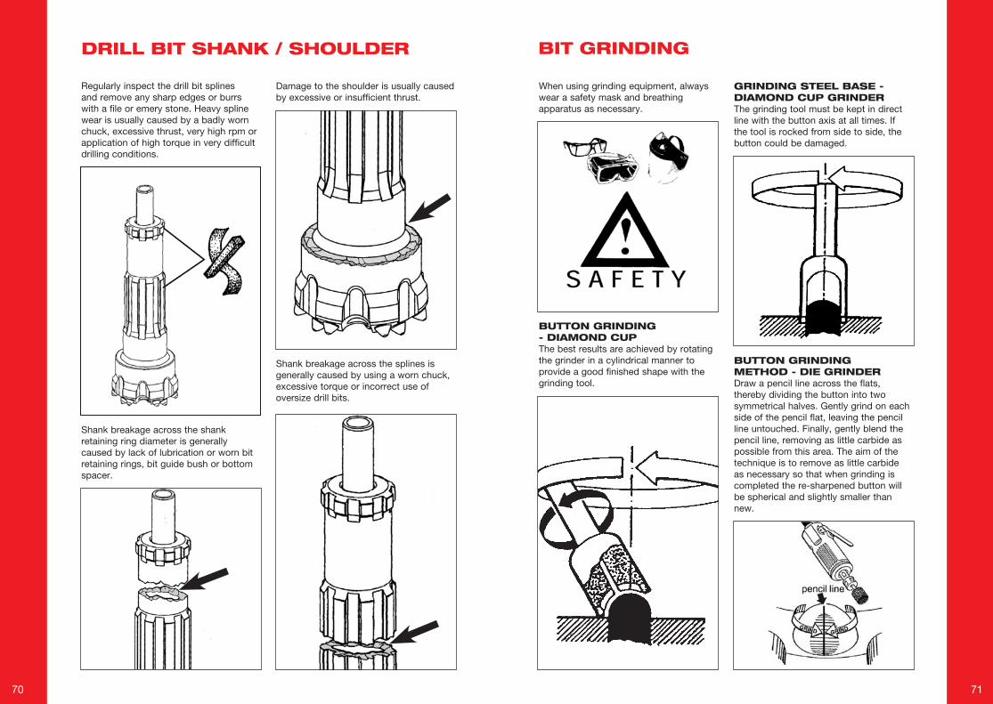
70 71
Regularly inspect the drill bit splines and remove any sharp edges or burrs with a file or emery stone. Heavy spline wear is usually caused by a badly worn chuck, excessive thrust, very high rpm or application of high torque in very difficult drilling conditions.
Shank breakage across the shank retaining ring diameter is generally caused by lack of lubrication or worn bit retaining rings, bit guide bush or bottom spacer.
Shank breakage across the splines is generally caused by using a worn chuck, excessive torque or incorrect use of oversize drill bits.
Damage to the shoulder is usually caused by excessive or insufficient thrust.
BUTTON GRINDING - DIAMOND CUPThe best results are achieved by rotating the grinder in a cylindrical manner to provide a good finished shape with the grinding tool.
GRINDING STEEL BASE - DIAMOND CUP GRINDERThe grinding tool must be kept in direct line with the button axis at all times. If the tool is rocked from side to side, the button could be damaged.
BUTTON GRINDING METHOD - DIE GRINDERDraw a pencil line across the flats, thereby dividing the button into two symmetrical halves. Gently grind on each side of the pencil flat, leaving the pencil line untouched. Finally, gently blend the pencil line, removing as little carbide as possible from this area. The aim of the technique is to remove as little carbide as necessary so that when grinding is completed the re-sharpened button will be spherical and slightly smaller than new.
When using grinding equipment, always wear a safety mask and breathing apparatus as necessary.
DRILL BIT SHANK / SHOULDER BIT GRINDING
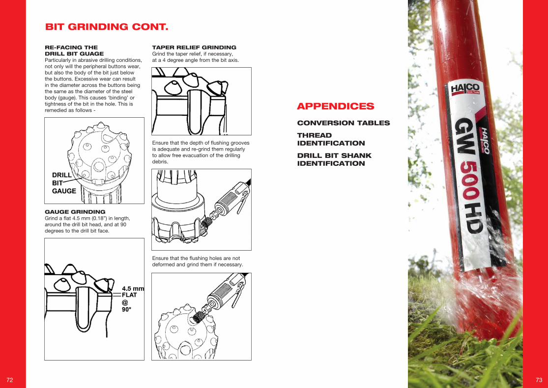
72 73
RE-FACING THE DRILL BIT GUAGEParticularly in abrasive drilling conditions, not only will the peripheral buttons wear, but also the body of the bit just below the buttons. Excessive wear can result in the diameter across the buttons being the same as the diameter of the steel body (gauge). This causes ‘binding’ or tightness of the bit in the hole. This is remedied as follows -
GAUGE GRINDINGGrind a flat 4.5 mm (0.18”) in length, around the drill bit head, and at 90 degrees to the drill bit face.
TAPER RELIEF GRINDINGGrind the taper relief, if necessary, at a 4 degree angle from the bit axis.
Ensure that the flushing holes are not deformed and grind them if necessary.
Ensure that the depth of flushing grooves is adequate and re-grind them regularly to allow free evacuation of the drilling debris.
BIT GRINDING CONT.
APPENDICES
CONVERSION TABLES
THREAD IDENTIFICATION
DRILL BIT SHANK IDENTIFICATION
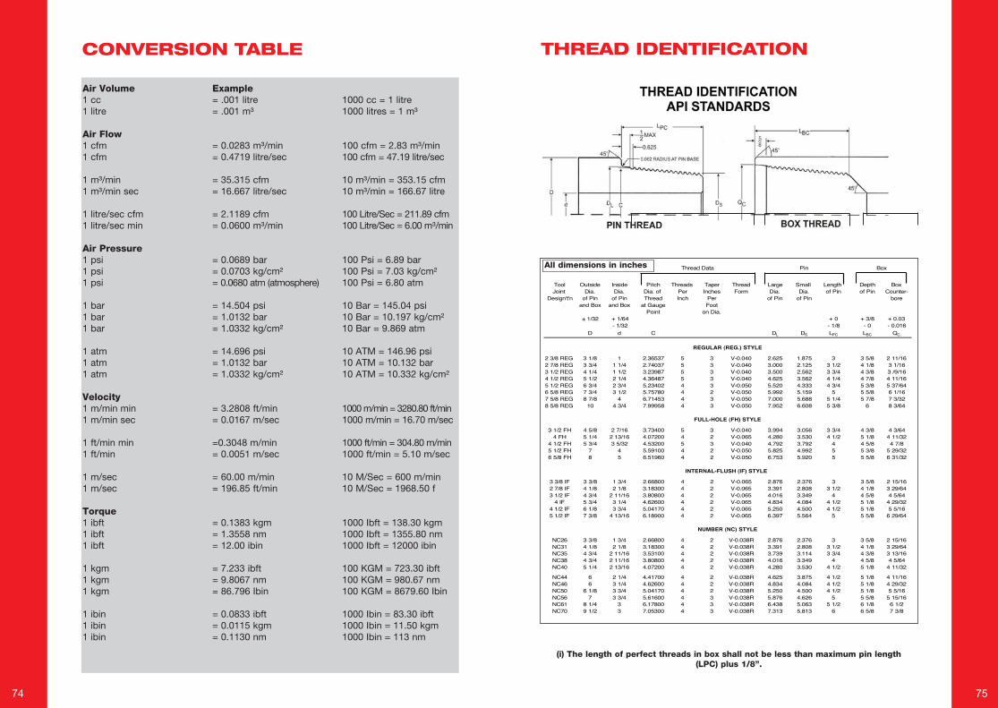
74 75
(i) The length of perfect threads in box shall not be less than maximum pin length (LPC) plus 1/8”.
CONVERSION TABLE
Air Volume1 cc1 litre
Air Flow1 cfm1 cfm
1 m³/min1 m³/min sec
1 litre/sec cfm1 litre/sec min
Air Pressure1 psi1 psi1 psi
1 bar1 bar1 bar
1 atm1 atm1 atm
Velocity1 m/min min1 m/min sec
1 ft/min min1 ft/min
1 m/sec1 m/sec
Torque1 ibft1 ibft1 ibft
1 kgm1 kgm1 kgm
1 ibin1 ibin1 ibin
Example= .001 litre= .001 m³
= 0.0283 m³/min= 0.4719 litre/sec
= 35.315 cfm= 16.667 litre/sec
= 2.1189 cfm= 0.0600 m³/min
= 0.0689 bar= 0.0703 kg/cm²= 0.0680 atm (atmosphere)
= 14.504 psi= 1.0132 bar= 1.0332 kg/cm²
= 14.696 psi= 1.0132 bar= 1.0332 kg/cm²
= 3.2808 ft/min= 0.0167 m/sec
=0.3048 m/min= 0.0051 m/sec
= 60.00 m/min= 196.85 ft/min
= 0.1383 kgm= 1.3558 nm= 12.00 ibin
= 7.233 ibft= 9.8067 nm= 86.796 Ibin
= 0.0833 ibft= 0.0115 kgm= 0.1130 nm
1000 cc = 1 litre1000 litres = 1 m³
100 cfm = 2.83 m³/min100 cfm = 47.19 litre/sec
10 m³/min = 353.15 cfm10 m³/min = 166.67 litre
100 Litre/Sec = 211.89 cfm100 Litre/Sec = 6.00 m³/min
100 Psi = 6.89 bar100 Psi = 7.03 kg/cm²100 Psi = 6.80 atm
10 Bar = 145.04 psi10 Bar = 10.197 kg/cm²10 Bar = 9.869 atm
10 ATM = 146.96 psi10 ATM = 10.132 bar10 ATM = 10.332 kg/cm²
1000 m/min = 3280.80 ft/min1000 m/min = 16.70 m/sec
1000 ft/min = 304.80 m/min1000 ft/min = 5.10 m/sec
10 M/Sec = 600 m/min10 M/Sec = 1968.50 f
1000 Ibft = 138.30 kgm1000 Ibft = 1355.80 nm1000 Ibft = 12000 ibin
100 KGM = 723.30 ibft100 KGM = 980.67 nm100 KGM = 8679.60 Ibin
1000 Ibin = 83.30 ibft1000 Ibin = 11.50 kgm1000 Ibin = 113 nm
THREAD IDENTIFICATION
Tool Outside Inside Pitch Threads Taper Thread Large Small Length Depth BoxJoint Dia. Dia. Dia. of Per Inches Form Dia. Dia. of Pin of Pin Counter-
Design't'n of Pin of Pin Thread Inch Per of Pin of Pin boreand Box and Box at Gauge Foot
Point on Dia.± 1/32 + 1/64 + 0 + 3/8 + 0.03
- 1/32 - 1/8 - 0 - 0.016D d C DL DS LPC LBC QC
2 3/8 REG 3 1/8 1 2.36537 5 3 V-0.040 2.625 1.875 3 3 5/8 2 11/162 7/8 REG 3 3/4 1 1/4 2.74037 5 3 V-0.040 3.000 2.125 3 1/2 4 1/8 3 1/163 1/2 REG 4 1/4 1 1/2 3.23987 5 3 V-0.040 3.500 2.562 3 3/4 4 3/8 3 /9/164 1/2 REG 5 1/2 2 1/4 4.36487 5 3 V-0.040 4.625 3.562 4 1/4 4 7/8 4 11/165 1/2 REG 6 3/4 2 3/4 5.23402 4 3 V-0.050 5.520 4.333 4 3/4 5 3/8 5 37/646 5/8 REG 7 3/4 3 1/2 5.75780 4 2 V-0.050 5.992 5.159 5 5 5/8 6 1/167 5/8 REG 8 7/8 4 6.71453 4 3 V-0.050 7.000 5.688 5 1/4 5 7/8 7 3/328 5/8 REG 10 4 3/4 7.99958 4 3 V-0.050 7.952 6.608 5 3/8 6 8 3/64
3 1/2 FH 4 5/8 2 7/16 3.73400 5 3 V-0.040 3.994 3.056 3 3/4 4 3/8 4 3/644 FH 5 1/4 2 13/16 4.07200 4 2 V-0.065 4.280 3.530 4 1/2 5 1/8 4 11/32
4 1/2 FH 5 3/4 3 5/32 4.53200 5 3 V-0.040 4.792 3.792 4 4 5/8 4 7/85 1/2 FH 7 4 5.59100 4 2 V-0.050 5.825 4.992 5 5 3/8 5 29/326 5/8 FH 8 5 6.51960 4 2 V-0.050 6.753 5.920 5 5 5/8 6 31/32
3 3/8 IF 3 3/8 1 3/4 2.66800 4 2 V-0.065 2.876 2.376 3 3 5/8 2 15/162 7/8 IF 4 1/8 2 1/8 3.18300 4 2 V-0.065 3.391 2.808 3 1/2 4 1/8 3 29/643 1/2 IF 4 3/4 2 11/16 3.80800 4 2 V-0.065 4.016 3.349 4 4 5/8 4 5/64
4 IF 5 3/4 3 1/4 4.62600 4 2 V-0.065 4.834 4.084 4 1/2 5 1/8 4 29/324 1/2 IF 6 1/8 3 3/4 5.04170 4 2 V-0.065 5.250 4.500 4 1/2 5 1/8 5 5/165 1/2 IF 7 3/8 4 13/16 6.18900 4 2 V-0.065 6.397 5.564 5 5 5/8 6 29/64
NC26 3 3/8 1 3/4 2.66800 4 2 V-0.038R 2.876 2.376 3 3 5/8 2 15/16NC31 4 1/8 2 1/8 3.18300 4 2 V-0.038R 3.391 2.808 3 1/2 4 1/8 3 29/64NC35 4 3/4 2 11/16 3.53100 4 2 V-0.038R 3.739 3.114 3 3/4 4 3/8 3 13/16NC38 4 3/4 2 11/16 3.80800 4 2 V-0.038R 4.016 3.349 4 4 5/8 4 5/64NC40 5 1/4 2 13/16 4.07200 4 2 V-0.038R 4.280 3.530 4 1/2 5 1/8 4 11/32
NC44 6 2 1/4 4.41700 4 2 V-0.038R 4.625 3.875 4 1/2 5 1/8 4 11/16NC46 6 3 1/4 4.62600 4 2 V-0.038R 4.834 4.084 4 1/2 5 1/8 4 29/32NC50 6 1/8 3 3/4 5.04170 4 2 V-0.038R 5.250 4.500 4 1/2 5 1/8 5 5/16NC56 7 3 3/4 5.61600 4 3 V-0.038R 5.876 4.626 5 5 5/8 5 15/16NC61 8 1/4 3 6.17800 4 3 V-0.038R 6.438 5.063 5 1/2 6 1/8 6 1/2NC70 9 1/2 3 7.05300 4 3 V-0.038R 7.313 5.813 6 6 5/8 7 3/8
FULL-HOLE (FH) STYLE
INTERNAL-FLUSH (IF) STYLE
NUMBER (NC) STYLE
Thread Data Pin Box
REGULAR (REG.) STYLE
All dimensions in inches
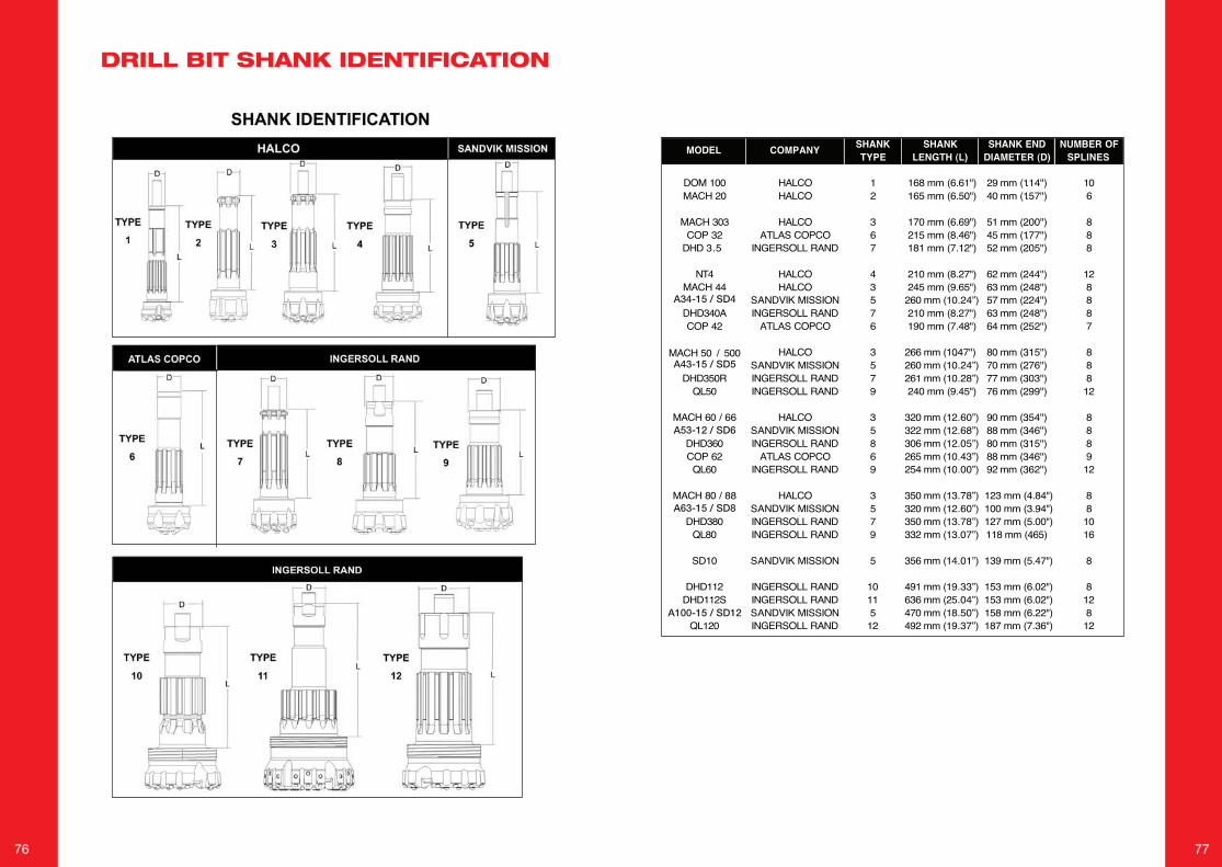
76 77
DRILL BIT SHANK IDENTIFICATION
SHANK IDENTIFICATION Cont......
SHANK SHANK SHANK END NUMBER OFTYPE LENGTH (L) DIAMETER (D) SPLINES
DOM 100 HALCO 1 168 mm (6.61") 29 mm (1.14") 10MACH 20 HALCO 2 165 mm (6.50") 40 mm (1.57") 6
MACH 303 HALCO 3 170 mm (6.69") 51 mm (2.00") 8COP 32 ATLAS COPCO 6 215 mm (8.46") 45 mm (1.77") 8
DHD 3.5 INGERSOLL RAND 7 181 mm (7.12") 52 mm (2.05") 8
NT4 HALCO 4 210 mm (8.27") 62 mm (2.44") 12MACH 44 HALCO 3 245 mm (9.65") 63 mm (2.48") 8
SANDVIK MISSION 5 260 mm (10.24”) 57 mm (2.24") 8DHD340A INGERSOLL RAND 7 210 mm (8.27") 63 mm (2.48") 8COP 42 ATLAS COPCO 6 190 mm (7.48") 64 mm (2.52") 7
MACH 50 / 500 HALCO 3 266 mm (10.47") 80 mm (3.15") 8SANDVIK MISSION 5 260 mm (10.24”) 70 mm (2.76") 8
DHD350R INGERSOLL RAND 7 261 mm (10.28”) 77 mm (3.03") 8QL50 INGERSOLL RAND 9 240 mm (9.45") 76 mm (2.99") 12
MACH 60 / 66 HALCO 3 320 mm (12.60”) 90 mm (3.54") 8SANDVIK MISSION 5 322 mm (12.68”) 88 mm (3.46") 8
DHD360 INGERSOLL RAND 8 306 mm (12.05”) 80 mm (3.15") 8COP 62 ATLAS COPCO 6 265 mm (10.43”) 88 mm (3.46") 9
QL60 INGERSOLL RAND 9 254 mm (10.00”) 92 mm (3.62") 12
MACH 80 / 88 HALCO 3 350 mm (13.78”) 123 mm (4.84") 8SANDVIK MISSION 5 320 mm (12.60”) 100 mm (3.94") 8
DHD380 INGERSOLL RAND 7 350 mm (13.78”) 127 mm (5.00") 10QL80 INGERSOLL RAND 9 332 mm (13.07”) 118 mm (4.65) 16
SD10 SANDVIK MISSION 5 356 mm (14.01”) 139 mm (5.47") 8
DHD112 INGERSOLL RAND 10 491 mm (19.33”) 153 mm (6.02") 8DHD112S INGERSOLL RAND 11 636 mm (25.04”) 153 mm (6.02") 12
SANDVIK MISSION 5 470 mm (18.50”) 158 mm (6.22") 8QL120 INGERSOLL RAND 12 492 mm (19.37”) 187 mm (7.36") 12
MODEL COMPANY
A34-15 / SD4
A43-15 / SD5
A53-12 / SD6
A63-15 / SD8
A100-15 / SD12

78 79
NOTES NOTES

80
Halco Rock Tools LimitedPO Box 25, West lane Southowram, Halifax, HX3 9TWTel: + 44 (0) 1422 399900Fax: + 44 (0) 1422 330186Email: [email protected]
Halco America Inc.3501 S. FM Hwy. 1417Denison, TX 75020 Tel: + 1 903 337 4190Fax: + 1 903 337 4191Email: [email protected]
Halco Australia2 Reid Road, Perth International Airport, Perth WA61054Tel: + 61 8 9248 4144 Fax: + 61 8 9248 4155Email: [email protected]
for more info visit:halcorocktools.com
Our aim is to provide excellent service that reflects your needs and exceeds your expectations. Our trained customer support team is dedicated to providing you what you want and when you need it. With over 60 years experience in assisting customers with their drilling applications, our support team has gained the expertise to provide an accurate and timely response.
WARRANTYOur warranty on hammers and bitsprovides you an ease of mind that any problem that might occur will be solved quickly and effectively by our experienced customer support team.
TRAINING SESSIONSTraining is available at any of ourlocations. Our distributors are trained and available locally for support as well. Training includes selection, service, maintenance and repair.
TECHNICAL SUPPORTTechnical support is always ready toassist you. Whether you need service or maintenance tips, troubleshooting, or advice on a repair, help is only a phone call away.
Our service engineers are happy to make on-site visits too.
PUBLICATIONSWhen you want to learn more about DTH drilling or product maintenance to improve efficiency, we have established 4 books to help you.
• A to Z of DTH Drilling• DTH maintenance manual• DTH maintenance RC hammers• Maintenance Sim-Cas
We are committed to help ourcustomers realise their full potential. Just as we constantly innovate and improve our hammers and bits, we want to continually evolve our company to be in the best position to accelerate new technologies as they emerge and to better serveour customers.
OUR COMMITMENT TO YOU
Halco Rock Tools Quality Management System is Certified to ISO9001: 2008 Certificate No: LRQ 0850659
Related Documents