II (Non-legislative acts) REGULATIONS COMMISSION IMPLEMENTING REGULATION (EU) 2016/1375 of 29 July 2016 amending Council Regulation (EU) No 267/2012 concerning restrictive measures against Iran THE EUROPEAN COMMISSION, Having regard to the Treaty on the Functioning of the European Union, Having regard to Council Regulation (EU) No 267/2012 ( 1 ), and in particular Article 45 thereof, Whereas: (1) Regulation (EU) No 267/2012 gives effect to the measures provided for in Decision 2010/413/CFSP of 26 July 2010 concerning restrictive measures against Iran and repealing Common Position 2007/140/CFSP ( 2 ). (2) On 18 October 2015, the Council adopted Council Regulation (EU) 2015/1861 ( 3 ) amending Regulation (EU) No 267/2012. (3) Regulation (EU) 2015/1861 introduced Annexes I and III and amended Annex VIIB, among others. Annex I comprises the items, including goods, technology and software, contained in the Nuclear Suppliers Group (NSG) list. Annex III comprises items, including goods and technology, contained in the Missile Technology Control Regime (MTCR) list. Annex VIIB contains a list of graphite and raw or semi-finished metals. (4) Article 45 of Regulation (EU) No 267/2012 empowers the Commission to amend Annexes I, III and VIIB. Pursuant to this Article and in order to facilitate implementation, Annexes I and III should be supplemented with information allowing a better identification of the items in those Annexes by reference to existing identifying codes as applied under Annex I to Council Regulation (EC) No 428/2009 ( 4 ). Moreover, certain technical amendments should also be made to Annex VIIB, HAS ADOPTED THIS REGULATION: Article 1 Regulation (EU) No 267/2012 is amended as follows: (1) Annex I is replaced by Annex I to this Regulation; (2) Annex III is replaced by Annex II to this Regulation; (3) Annex VIIB is replaced by Annex III to this Regulation. 16.8.2016 L 221/1 Official Journal of the European Union EN ( 1 ) Council Regulation (EU) No 267/2012 of 23 March 2012 concerning restrictive measures against Iran and repealing Regulation (EU) No 961/2010 (OJ L 88, 24.3.2012, p. 1). ( 2 ) OJ L 195, 27.7.2010. p. 39. ( 3 ) Council Regulation (EU) 2015/1861 of 18 October 2015 amending Regulation (EU) No 267/2012 concerning restrictive measures against Iran (OJ L 274, 18.10.2015, p. 1). ( 4 ) Council Regulation (EC) No 428/2009 of 5 May 2009 setting up a Community regime for the control of exports, transfer, brokering and transit of dual-use items (OJ L 134, 29.5.2009, p. 1).

Welcome message from author
This document is posted to help you gain knowledge. Please leave a comment to let me know what you think about it! Share it to your friends and learn new things together.
Transcript
II
(Non-legislative acts)
REGULATIONS
COMMISSION IMPLEMENTING REGULATION (EU) 2016/1375
of 29 July 2016
amending Council Regulation (EU) No 267/2012 concerning restrictive measures against Iran
THE EUROPEAN COMMISSION,
Having regard to the Treaty on the Functioning of the European Union,
Having regard to Council Regulation (EU) No 267/2012 (1), and in particular Article 45 thereof,
Whereas:
(1) Regulation (EU) No 267/2012 gives effect to the measures provided for in Decision 2010/413/CFSP of 26 July 2010 concerning restrictive measures against Iran and repealing Common Position 2007/140/CFSP (2).
(2) On 18 October 2015, the Council adopted Council Regulation (EU) 2015/1861 (3) amending Regulation (EU) No 267/2012.
(3) Regulation (EU) 2015/1861 introduced Annexes I and III and amended Annex VIIB, among others. Annex I comprises the items, including goods, technology and software, contained in the Nuclear Suppliers Group (NSG) list. Annex III comprises items, including goods and technology, contained in the Missile Technology Control Regime (MTCR) list. Annex VIIB contains a list of graphite and raw or semi-finished metals.
(4) Article 45 of Regulation (EU) No 267/2012 empowers the Commission to amend Annexes I, III and VIIB. Pursuant to this Article and in order to facilitate implementation, Annexes I and III should be supplemented with information allowing a better identification of the items in those Annexes by reference to existing identifying codes as applied under Annex I to Council Regulation (EC) No 428/2009 (4). Moreover, certain technical amendments should also be made to Annex VIIB,
HAS ADOPTED THIS REGULATION:
Article 1
Regulation (EU) No 267/2012 is amended as follows:
(1) Annex I is replaced by Annex I to this Regulation;
(2) Annex III is replaced by Annex II to this Regulation;
(3) Annex VIIB is replaced by Annex III to this Regulation.
16.8.2016 L 221/1 Official Journal of the European Union EN
(1) Council Regulation (EU) No 267/2012 of 23 March 2012 concerning restrictive measures against Iran and repealing Regulation (EU) No 961/2010 (OJ L 88, 24.3.2012, p. 1).
(2) OJ L 195, 27.7.2010. p. 39. (3) Council Regulation (EU) 2015/1861 of 18 October 2015 amending Regulation (EU) No 267/2012 concerning restrictive measures
against Iran (OJ L 274, 18.10.2015, p. 1). (4) Council Regulation (EC) No 428/2009 of 5 May 2009 setting up a Community regime for the control of exports, transfer, brokering and
transit of dual-use items (OJ L 134, 29.5.2009, p. 1).

Article 2
This Regulation shall enter into force on the day following that of its publication in the Official Journal of the European Union.
This Regulation shall be binding in its entirety and directly applicable in all Member States.
Done at Brussels, 29 July 2016.
For the Commission,
On behalf of the President,
Head of the Service for Foreign Policy Instruments
16.8.2016 L 221/2 Official Journal of the European Union EN

ANNEX I
‘ANNEX I
CATEGORY 0 — NUCLEAR MATERIALS, FACILITIES, AND EQUIPMENT
0A Systems, Equipment and Components
The corresponding systems, equipment and components as identified in Council Regulation (EC) No 428/2009 of 5 May 2009 setting up a Community regime for the control of exports, transfer,
brokering and transit of dual-use items Nuclear Suppliers Group's control list as in INFCIRC/254/Rev.12/Part 1 (1)
0A001 “Nuclear reactors” and specially designed or prepared equipment and components therefor, as follows:
TLB1.1 Complete nuclear reactors
0A001.a “Nuclear reactors”; TLB1.1 Nuclear reactors capable of operation so as to maintain a controlled self-sustaining fission chain reaction.
EXPLANATORY NOTE A “nuclear reactor” basically includes the items within or attached directly to the reactor vessel, the equipment which controls the level of power in the core, and the components which normally contain or come in direct contact with or control the primary coolant of the reactor core. EXPORTS The export of the whole set of major items within this boundary will take place only in accordance with the procedures of the Guidelines. Those individual items within this functionally defined boundary which will be exported only in accordance with the procedures of the Guidelines are listed in paragraphs 1.2. to 1.11. The Government reserves to itself the right to apply the procedures of the Guidelines to other items within the functionally defined boundary
0A001.b Metal vessels, or major shop-fabricated parts therefor, including the reactor vessel head for a reactor pressure vessel, specially designed or prepared to contain the core of a “nuclear reactor”;
TLB1.2 Nuclear reactor vessels Metal vessels, or major shop-fabricated parts therefor, especially designed or prepared to contain the core of a nuclear reactor as defined in paragraph 1.1. above, as well as relevant reactor internals as defined in paragraph 1.8. below.
EXPLANATORY NOTE Item 1.2 covers nuclear reactor vessels regardless of pressure rating and includes reactor pressure vessels and calandrias. The reactor vessel head is covered by item 1.2. as a major shop-fabricated part of a reactor vessel.
16.8.2016 L 221/3
Official Journal of the European U
nion EN

0A001.c Manipulative equipment specially designed or prepared for inserting or removing fuel in a “nuclear reactor”;
TLB1.3 Nuclear reactor fuel charging and discharging machines Manipulative equipment especially designed or prepared for inserting or removing fuel in a nuclear reactor as defined in paragraph 1.1. above.
EXPLANATORY NOTE The items noted above are capable of on-load operation or at employing technically sophisticated positioning or alignment features to allow complex off-load fueling operations such as those in which direct viewing of or access to the fuel is not normally available.
0A001.d Control rods specially designed or prepared for the control of the fission process in a “nuclear reactor”, support or suspension structures therefor, rod drive mechanisms and rod guide tubes;
TLB1.4 Nuclear reactor control rods and equipment Especially designed or prepared rods, support or suspension structures therefor, rod drive mechanisms or rod guide tubes to control the fission process in a nuclear reactor as defined in paragraph 1.1. above.
0A001.e Pressure tubes specially designed or prepared to contain both fuel elements and the primary coolant in a “nuclear reactor”;
TLB1.5 Nuclear reactor pressure tubes Tubes which are especially designed or prepared to contain both fuel elements and the primary coolant in a reactor as defined in paragraph 1.1. above.
EXPLANATORY NOTE Pressure tubes are parts of fuel channels designed to operate at elevated pressure, sometimes in excess of 5 MPa.
0A001.f Zirconium metal tubes or zirconium alloy tubes (or assembles of tubes) specially designed or prepared for use as fuel cladding in a “nuclear reactor”, and in quantities exceeding 10 kg;
N.B.: For zirconium pressure tubes see 0A001.e. and for calandria tubes see 0A001.h.
TLB1.6 Nuclear fuel cladding Zirconium metal tubes or zirconium alloy tubes (or assemblies of tubes) especially designed or prepared for use as fuel cladding in a reactor as defined in paragraph 1.1. above, and in quantities exceeding 10 kg.
N.B.: For zirconium pressure tubes see 1.5. For calandria tubes see 1.8.
EXPLANATORY NOTE Zirconium metal tubes or zirconium alloy tubes for use in a nuclear reactor consist of zirconium in which the relation of hafnium to zirconium is typically less than 1:500 parts by weight
16.8.2016 L 221/4
Official Journal of the European U
nion EN
0A001.g Coolant pumps or circulators specially designed or prepared for circulating the primary coolant of “nuclear reactors”;
TLB1.7 Primary coolant pumps or circulators Pumps or circulators especially designed or prepared for circulating the primary coolant for nuclear reactors as defined in paragraph 1.1. above.
EXPLANATORY NOTE: Especially designed or prepared pumps or circulators include pumps for water-cooled reactors, circulators for gas-cooled reactors, and electromagnetic and mechanical pumps for liquid-metal-cooled reactors. This equipment may include pumps with elaborate sealed or multi-sealed systems to prevent leakage of primary coolant, canned-driven pumps, and pumps with inertial mass systems. This definition encompasses pumps certified to Section III, Division I, Subsection NB (Class 1 components) of the American Society of Mechanical Engineers (ASME) Code, or equivalent standards.
0A001.h ‘Nuclear reactor internals’ specially designed or prepared for use in a “nuclear reactor”, including support columns for the core, fuel channels, calandria tubes, thermal shields, baffles, core grid plates, and diffuser plates;
Technical Note:
In 0A001.h. ‘nuclear reactor internals’ means any major structure within a reactor vessel which has one or more functions such as supporting the core, maintaining fuel alignment, directing primary coolant flow, providing radiation shields for the reactor vessel, and guiding in-core instrumentation.
TLB1.8 Nuclear reactor internals “Nuclear reactor internals” especially designed or prepared for use in a nuclear reactor as defined in paragraph 1.1 above. This includes, for example, support columns for the core, fuel channels, calandria tubes, thermal shields, baffles, core grid plates, and diffuser plates.
EXPLANATORY NOTE “Nuclear reactor internals” are major structures within a reactor vessel which have one or more functions such as supporting the core, maintaining fuel alignment, directing primary coolant flow, providing radiation shields for the reactor vessel, and guiding in-core instrumentation.
0A001.i Heat exchangers as follows:
1. Steam generators specially designed or prepared for the primary, or intermediate, coolant circuit of a “nuclear reactor”;
2. Other heat exchangers specially designed or prepared for use in the primary coolant circuit of a “nuclear reactor”;
Note: 0A001.i. does not control heat exchangers for the supporting systems of the reactor, e.g., the emergency cooling system or the decay heat cooling system.
TLB1.9 Heat exchangers (a) Steam generators especially designed or prepared for the primary, or intermediate, coolant circuit of a nuclear reactor as defined in paragraph 1.1 above. (b) Other heat exchangers especially designed or prepared for use in the primary coolant circuit of a nuclear reactor as defined in paragraph 1.1 above.
EXPLANATORY NOTE Steam generators are especially designed or prepared to transfer the heat generated in the reactor to the feed water for steam generation. In the case of a fast reactor for which an intermediate coolant loop is also present, the steam generator is in the intermediate circuit. In a gas-cooled reactor, a heat exchanger may be utilized to transfer heat to a secondary gas loop that drives a gas turbine. The scope of control for this entry does not include heat exchangers for the supporting systems of the reactor, e.g., the emergency cooling system or the decay heat cooling system.
16.8.2016 L 221/5
Official Journal of the European U
nion EN
0A001.j Neutron detectors specially designed or prepared for determining neutron flux levels within the core of a “nuclear reactor”;
TLB1.10 Neutron detectors Especially designed or prepared neutron detectors for determining neutron flux levels within the core of a reactor as defined in paragraph 1.1. above.
EXPLANATORY NOTE The scope of this entry encompasses in-core and ex- core detectors which measure flux levels in a large range, typically from 104
neutrons per cm2 per second to 1010 neutrons per cm2 per second or more. Ex-core refers to those instruments outside the core of a reactor as defined in paragraph 1.1. above, but located within the biological shielding.
0A001.k ‘External thermal shields’ specially designed or prepared for use in a “nuclear reactor” for the reduction of heat loss and also for the containment vessel protection.
Technical Note:
In 0A001.k. ‘external thermal shields’ means major structures placed over the reactor vessel which reduce heat loss from the reactor and reduce temperature within the containment vessel.
TLB1.11 External thermal shields “External thermal shields” especially designed or prepared for use in a nuclear reactor as defined in paragraph 1.1 for reduction of heat loss and also for containment vessel protection.
EXPLANATORY NOTE “External thermal shields” are major structures placed over the reactor vessel which reduce heat loss from the reactor and reduce temperature within the containment vessel.
0B001 Plant for the separation of isotopes of “natural uranium”, “depleted uranium” or “special fissile materials”, and specially designed or prepared equipment and components therefor, as follows:
TLB5 Plants for the separation of isotopes of natural uranium, depleted uranium or special fissionable material and equipment, other than analytical instruments, especially designed or prepared therefor
0B001.a Plant specially designed for separating isotopes of “natural uranium”, “depleted uranium”, or “special fissile materials”, as follows:
1. Gas centrifuge separation plant;
2. Gaseous diffusion separation plant;
3. Aerodynamic separation plant;
4. Chemical exchange separation plant;
5. Ion-exchange separation plant;
6. Atomic vapour “laser” isotope separation plant;
7. Molecular “laser” isotope separation plant;
8. Plasma separation plant;
9. Electro magnetic separation plant;
TLB5
16.8.2016 L 221/6
Official Journal of the European U
nion EN
0B001.b Gas centrifuges and assemblies and components, specially designed or prepared for gas centrifuge separation process, as follows:
Technical Note:
In 0B001.b. ‘high strength-to-density ratio material’ means any of the following:
1. Maraging steel capable of an ultimate tensile strength of 1,95 GPa or more;
2. Aluminium alloys capable of an ultimate tensile strength of 0,46 GPa or more; or
3. “Fibrous or filamentary materials” with a “specific modulus” of more than 3,18 × 10⁶ m and a “specific tensile strength” greater than 7,62 × 10⁴ m;
1. Gas centrifuges;
TLB5.1 5.1. Gas centrifuges and assemblies and components especially designed or prepared for use in gas centrifuges
INTRODUCTORY NOTE
The gas centrifuge normally consists of a thin-walled cylinder(s) of between 75 mm and 650 mm diameter contained in a vacuum environment and spun at high peripheral speed of the order of 300 m/s or more with its central axis vertical. In order to achieve high speed the materials of construction for the rotating components have to be of a high strength to density ratio and the rotor assembly, and hence its individual components, have to be manufactured to very close tolerances in order to minimize the unbalance. In contrast to other centrifuges, the gas centrifuge for uranium enrichment is characterized by having within the rotor chamber a rotating disc-shaped baffle(s) and a stationary tube arrangement for feeding and extracting the UF6 gas and featuring at least three separate channels, of which two are connected to scoops extending from the rotor axis towards the periphery of the rotor chamber. Also contained within the vacuum environment are a number of critical items which do not rotate and which although they are especially designed are not difficult to fabricate nor are they fabricated out of unique materials. A centrifuge facility however requires a large number of these components, so that quantities can provide an important indication of end use.
0B001.b TLB5.1.1 Rotating components
0B001.b. 2. Complete rotor assemblies; TLB5.1.1a (a) Complete rotor assemblies:
Thin-walled cylinders, or a number of interconnected thin-walled cylinders, manufactured from one or more of the high strength to density ratio materials described in the EXPLANATORY NOTE to this Section. If interconnected, the cylinders are joined together by flexible bellows or rings as described in section 5.1.1.(c) following. The rotor is fitted with an internal baffle(s) and end caps, as described in section 5.1.1.(d) and (e) following, if in final form. However the complete assembly may be delivered only partly assembled.
0B001.b. 3. Rotor tube cylinders with a wall thickness of 12 mm or less, a diameter of between 75 mm and 650 mm, made from ‘high strength-to-density ratio materials’;
TLB5.1.1b (b) Rotor tubes:
Especially designed or prepared thin-walled cylinders with thickness of 12 mm or less, a diameter of between 75 mm and 650 mm, and manufactured from one or more of the high strength to density ratio materials described in the EXPLANATORY NOTE to this Section.
16.8.2016 L 221/7
Official Journal of the European U
nion EN
0B001.b. 4. Rings or bellows with a wall thickness of 3 mm or less and a diameter of between 75 mm and 650 mm and designed to give local support to a rotor tube or to join a number together, made from ‘high strength-to-density ratio materials’;
TLB5.1.1c (c) Rings or Bellows:
Components especially designed or prepared to give localized support to the rotor tube or to join together a number of rotor tubes. The bellows is a short cylinder of wall thickness 3 mm or less, a diameter of between 75 mm and 650 mm, having a convolute, and manufactured from one of the high strength to density ratio materials described in the EXPLANATORY NOTE to this Section.
0B001.b. 5. Baffles of between 75 mm and 650 mm diameter for mounting inside a rotor tube, made from ‘high strength-to-density ratio materials’.
TLB5.1.1d (d) Baffles:
Disc-shaped components of between 75 mm and 650 mm diameter especially designed or prepared to be mounted inside the centrifuge rotor tube, in order to isolate the take-off chamber from the main separation chamber and, in some cases, to assist the UF6 gas circulation within the main separation chamber of the rotor tube, and manufactured from one of the high strength to density ratio materials described in the EXPLANATORY NOTE to this Section.
0B001.b. 6. Top or bottom caps of between 75 mm and 650 mm diameter to fit the ends of a rotor tube, made from ‘high strength-to-density ratio materials’;
TLB5.1.1e (e) Top caps/Bottom caps:
Disc-shaped components of between 75 mm and 650 mm diameter especially designed or prepared to fit to the ends of the rotor tube, and so contain the UF6 within the rotor tube, and in some cases to support, retain or contain as an integrated part an element of the upper bearing (top cap) or to carry the rotating elements of the motor and lower bearing (bottom cap), and manufactured from one of the high strength to density ratio materials described in the EXPLANATORY NOTE to this Section.
TLB5.1.1 EXPLANATORY NOTE
The materials used for centrifuge rotating components include the following:
(a) Maraging steel capable of an ultimate tensile strength of 1,95 GPa or more;
(b) Aluminium alloys capable of an ultimate tensile strength of 0,46 GPa or more;
(c) Filamentary materials suitable for use in composite structures and having a specific modulus of 3,18 × 10⁶ m or greater and a specific ultimate tensile strength of 7,62 × 10⁴ m or greater (‘Specific Modulus’ is the Young's Modulus in N/m2 divided by the specific weight in N/m3; ‘Specific Ultimate Tensile Strength’ is the ultimate tensile strength in N/m2 divided by the specific weight in N/m3).
16.8.2016 L 221/8
Official Journal of the European U
nion EN

0B001.b TLB5.1.2 Static components
0B001.b. 7. Magnetic suspension bearings as follows:
a. Bearing assemblies consisting of an annular magnet suspended within a housing made of or protected by “materials resistant to corrosion by UF6” containing a damping medium and having the magnet coupling with a pole piece or second magnet fitted to the top cap of the rotor;
b. Active magnetic bearings specially designed or prepared for use with gas centrifuges.
TLB5.1.2A.1 (a) Magnetic suspension bearings:
1. Especially designed or prepared bearing assemblies consisting of an annular magnet suspended within a housing containing a damping medium. The housing will be manufactured from a UF6-resistant material (see EXPLANATORY NOTE to Section 5.2.). The magnet couples with a pole piece or a second magnet fitted to the top cap described in Section 5.1.1.(e).
The magnet may be ring-shaped with a relation between outer and inner diameter smaller or equal to 1,6:1. The magnet may be in a form having an initial permeability of 0,15 H/m or more, or a remanence of 98,5 % or more, or an energy product of greater than 80 kJ/m3. In addition to the usual material properties, it is a prerequisite that the deviation of the magnetic axes from the geometrical axes is limited to very small tolerances (lower than 0,1 mm) or that homogeneity of the material of the magnet is specially called for.
0B001.b. TLB5.1.2a2 2. Active magnetic bearings especially designed or prepared for use with gas centrifuges.
EXPLANATORY NOTE
These bearings usually have the following characteristics:
— Designed to keep centred a rotor spinning at 600 Hz or more, and
— Associated to a reliable electrical power supply and/or to an uninterruptible power supply (UPS) unit in order to function for more than one hour.
0B001.b. 8. Specially prepared bearings comprising a pivot-cup assembly mounted on a damper;
TLB5.1.2b (b) Bearings/Dampers:
Especially designed or prepared bearings comprising a pivot/cup assembly mounted on a damper. The pivot is normally a hardened steel shaft with a hemisphere at one end with a means of attachment to the bottom cap described in section 5.1.1.(e) at the other. The shaft may however have a hydrodynamic bearing attached. The cup is pellet-shaped with a hemispherical indentation in one surface. These components are often supplied separately to the damper.
16.8.2016 L 221/9
Official Journal of the European U
nion EN
0B001.b. 9. Molecular pumps comprised of cylinders having internally machined or extruded helical grooves and internally machined bores;
TLB5.1.2c (c) Molecular pumps:
Especially designed or prepared cylinders having internally machined or extruded helical grooves and internally machined bores. Typical dimensions are as follows: 75 mm to 650 mm internal diameter, 10 mm or more wall thickness, with the length equal to or greater than the diameter. The grooves are typically rectangular in cross-section and 2 mm or more in depth.
0B001.b. 10. Ring-shaped motor stators for multiphase AC hysteresis (or reluctance) motors for synchronous operation within a vacuum at a frequency of 600 Hz or more and a power of 40 VA or more;
TLB5.1.2d (d) Motor stators:
Especially designed or prepared ring-shaped stators for high speed multiphase AC hysteresis (or reluctance) motors for synchronous operation within a vacuum at a frequency of 600 Hz or greater and a power of 40 VA or greater. The stators may consist of multi-phase windings on a laminated low loss iron core comprised of thin layers typically 2,0 mm thick or less.
0B001.b. 11. Centrifuge housing/recipients to contain the rotor tube assembly of a gas centrifuge, consisting of a rigid cylinder of wall thickness up to 30 mm with precision machined ends that are parallel to each other and perpendicular to the cylinder's longitudinal axis to within 0,05 degrees or less;
TLB5.1.2e (e) Centrifuge housing/recipients:
Components especially designed or prepared to contain the rotor tube assembly of a gas centrifuge. The housing consists of a rigid cylinder of wall thickness up to 30 mm with precision machined ends to locate the bearings and with one or more flanges for mounting. The machined ends are parallel to each other and perpendicular to the cylinder's longitudinal axis to within 0,05 degrees or less. The housing may also be a honeycomb type structure to accommodate several rotor assemblies.
0B001.b. 12. Scoops consisting of specially designed or prepared tubes for the extraction of UF6 gas from within the rotor tube by a Pitot tube action and capable of being fixed to the central gas extraction system;
TLB5.1.2f (f) Scoops:
Especially designed or prepared tubes for the extraction of UF6 gas from within the rotor tube by a Pitot tube action (that is, with an aperture facing into the circumferential gas flow within the rotor tube, for example by bending the end of a radially disposed tube) and capable of being fixed to the central gas extraction system.
0B001.b. 13. Frequency changers (converters or inverters) specially designed or prepared to supply motor stators for gas centrifuge enrichment, having all of the following characteristics, and specially designed components therefor:
a. A multiphase frequency output of 600 Hz or greater; and
b. High stability (with frequency control better than 0,2 %);
TLB5.2.5 5.2.5. Frequency changers Frequency changers (also known as converters or inverters) especially designed or prepared to supply motor stators as defined under 5.1.2.(d), or parts, components and sub-assemblies of such frequency changers having all of the following characteristics:
1. A multiphase frequency output of 600 Hz or greater; and
2. High stability (with frequency control better than 0,2 %).
16.8.2016 L 221/10
Official Journal of the European U
nion EN
0B001.b. 14. Shut-off and control valves as follows:
a. Shut-off valves specially designed or prepared to act on the feed, product or tails UF6 gaseous streams of an individual gas centrifuge;
b. Bellows-sealed valves, shut-off or control, made of or protected by “materials resistant to corrosion by UF6”, with an inside diameter of 10 mm to 160 mm, specially designed or prepared for use in main or auxiliary systems of gas centrifuge enrichment plants;
TLB5.2.3 5.2.3 Special shut-off and control valves (a) Shut-off valves especially designed or prepared to act on the feed, product
or tails UF6 gaseous streams of an individual gas centrifuge.
(b) Bellows-sealed valves, manual or automated, shut-off or control, made of or protected by materials resistant to corrosion by UF6, with an inside diameter of 10 to 160 mm, especially designed or prepared for use in main or auxiliary systems of gas centrifuge enrichment plants.
EXPLANATORY NOTE
Typical especially designed or prepared valves include bellow-sealed valves, fast acting closure-types, fast acting valves and others.
0B001.c Equipment and components, specially designed or prepared for gaseous diffusion separation process, as follows: 1. Gaseous diffusion barriers made of porous metallic, polymer or ceramic
“materials resistant to corrosion by UF6” with a pore size of 10 to 100 nm, a thickness of 5 mm or less, and, for tubular forms, a diameter of 25 mm or less;
TLB5.3.1a Gaseous diffusion barriers and barrier materials (a) Especially designed or prepared thin, porous filters, with a pore size of 10
— 100 nm, a thickness of 5 mm or less, and for tubular forms, a diameter of 25 mm or less, made of metallic, polymer or ceramic materials resistant to corrosion by UF6 (see EXPLANATORY NOTE to section 5.4), and
0B001.c 2. Gaseous diffuser housings made of or protected by “materials resistant to corrosion by UF6”;
TLB5.3.2 Diffuser housings Especially designed or prepared hermetically sealed vessels for containing the gaseous diffusion barrier, made of or protected by UF6-resistant materials (see EXPLANATORY NOTE to section 5.4).
0B001.c 3. Compressors or gas blowers with a suction volume capacity of 1 m3/min or more of UF6, discharge pressure up to 500 kPa and having a pressure ratio of 10:1 or less, and made of or protected by “materials resistant to corrosion by UF6”;
TLB5.3.3 Compressors and gas blowers Especially designed or prepared compressors or gas blowers with a suction volume capacity of 1 m3 per minute or more of UF6, and with a discharge pressure of up to 500 kPa, designed for long-term operation in the UF6 environment, as well as separate assemblies of such compressors and gas blowers. These compressors and gas blowers have a pressure ratio of 10:1 or less and are made of, or protected by, materials resistant to UF6 (see EXPLANATORY NOTE to section 5.4).
16.8.2016 L 221/11
Official Journal of the European U
nion EN
0B001.c 4. Rotary shaft seals for compressors or blowers specified in 0B001.c.3. and designed for a buffer gas in-leakage rate of less than 1 000 cm3/ min.;
TLB5.3.4 Rotary shaft seals Especially designed or prepared vacuum seals, with seal feed and seal exhaust connections, for sealing the shaft connecting the compressor or the gas blower rotor with the driver motor so as to ensure a reliable seal against in- leaking of air into the inner chamber of the compressor or gas blower which is filled with UF6. Such seals are normally designed for a buffer gas in-leakage rate of less than 1 000 cm3 per minute.
0B001.c 5. Heat exchangers made of or protected by “materials resistant to corrosion by UF6”, and designed for a leakage pressure rate of less than 10 Pa per hour under a pressure differential of 100 kPa
TLB5.3.5 Heat exchangers for cooling UF6
Especially designed or prepared heat exchangers made of or protected by UF6-resistant materials (see EXPLANATORY NOTE to section 5.4), and intended for a leakage pressure change rate of less than 10 Pa per hour under a pressure difference of 100 kPa.
0B001.c 6. Bellows-sealed valves, manual or automated, shut-off or control, made of or protected by “materials resistant to corrosion by UF6”;
TLB5.4.4 Special shut-off and control valves Especially designed or prepared bellows-sealed valves, manual or automated, shut-off or control, made of or protected by materials resistant to corrosion by UF6, for installation in main and auxiliary systems of gaseous diffusion enrichment plants.
0B001.d Equipment and components, specially designed or prepared for aerodynamic separation process, as follows: 1. Separation nozzles consisting of slit-shaped, curved channels having a ra
dius of curvature less than 1 mm, resistant to corrosion by UF6, and having a knife-edge contained within the nozzle which separates the gas flowing through the nozzle into two streams;
TLB5.5.1 Separation nozzles Especially designed or prepared separation nozzles and assemblies thereof. The separation nozzles consist of slit-shaped, curved channels having a radius of curvature less than 1 mm, resistant to corrosion by UF6 and having a knife-edge within the nozzle that separates the gas flowing through the nozzle into two fractions.
0B001.d 2. Cylindrical or conical tubes, (vortex tubes), made of or protected by “materials resistant to corrosion by UF6” and with one or more tangential inlets;
TLB5.5.2 Vortex tubes Especially designed or prepared vortex tubes and assemblies thereof. The vortex tubes are cylindrical or tapered, made of or protected by materials resistant to corrosion by UF6, and with one or more tangential inlets. The tubes may be equipped with nozzletype appendages at either or both ends.
EXPLANATORY NOTE The feed gas enters the vortex tube tangentially at one end or through swirl vanes or at numerous tangential positions along the periphery of the tube.
16.8.2016 L 221/12
Official Journal of the European U
nion EN

0B001.d 3. Compressors or gas blowers made of or protected by “materials resistant to corrosion by UF6”, and rotary shaft seals therefor;
TLB5.5.3
TLB5.5.4
Compressors and gas blowers Especially designed or prepared compressors or gas blowers made of or protected by materials resistant to corrosion by the UF6/carrier gas (hydrogen or helium) mixture.
Rotary shaft seals
Especially designed or prepared rotary shaft seals, with seal feed and seal exhaust connections, for sealing the shaft connecting the compressor rotor or the gas blower rotor with the driver motor so as to ensure a reliable seal against out-leakage of process gas or in-leakage of air or seal gas into the inner chamber of the compressor or gas blower which is filled with a UF6/carrier gas mixture.
0B001.d 4. Heat exchangers made of or protected by “materials resistant to corrosion by UF6”;
TLB5.5.5 Heat exchangers for gas cooling Especially designed or prepared heat exchangers made of or protected by materials resistant to corrosion by UF6.
0B001.d 5. Separation element housings, made of or protected by “materials resistant to corrosion by UF6” to contain vortex tubes or separation nozzles;
TLB5.5.6 Separation element housings Especially designed or prepared separation element housings, made of or protected by materials resistant to corrosion by UF6, for containing vortex tubes or separation nozzles.
0B001.d 6. Bellows-sealed valves, manual or automated, shut-off or control, made of or protected by “materials resistant to corrosion by UF6”, with a diameter of 40 mm or more;
TLB5.5.10 UF6 mass spectrometers/Ion sources Especially designed or prepared mass spectrometers capable of taking on-line samples from UF6 gas streams and having all of the following:
1. Capable of measuring ions of 320 atomic mass units or greater and having a resolution of better than 1 part in 320;
2. Ion sources constructed of or protected by nickel, nickel-copper alloys with a nickel content of 60 % or more by weight, or nickel-chrome alloys;
3. Electron bombardment ionization sources;
4. Having a collector system suitable for isotopic analysis.
16.8.2016 L 221/13
Official Journal of the European U
nion EN
0B001.d 7. Process systems for separating UF6 from carrier gas (hydrogen or helium) to 1 ppm UF6 content or less, including:
a. Cryogenic heat exchangers and cryoseparators capable of temperatures of 153K (–120 °C) or less;
b. Cryogenic refrigeration units capable of temperatures of 153 K (–120 °C) or less;
c. Separation nozzle or vortex tube units for the separation of UF6 from carrier gas;
d. UF6 cold traps capable of freezing out UF6;
TLB5.5.12 UF6/carrier gas separation systems Especially designed or prepared process systems for separating UF6 from carrier gas (hydrogen or helium).
EXPLANATORY NOTE These systems are designed to reduce the UF6 content in the carrier gas to 1 ppm or less and may incorporate equipment such as:
(a) Cryogenic heat exchangers and cryoseparators capable of temperatures of 153 K (– 120 °C) or less, or
(b) Cryogenic refrigeration units capable of temperatures of 153 K (–120 °C) or less, or
(c) Separation nozzle or vortex tube units for the separation of UF6 from carrier gas, or
(d) UF6 cold traps capable of freezing out UF6.
0B001.e Equipment and components, specially designed or prepared for chemical exchange separation process, as follows:
1. Fast-exchange liquid-liquid pulse columns with stage residence time of 30 seconds or less and resistant to concentrated hydrochloric acid (e.g. made of or protected by suitable plastic materials such as fluorinated hydrocarbon polymers or glass)
TLB5.6.1 Liquid-liquid exchange columns (Chemical exchange)
Countercurrent liquid-liquid exchange columns having mechanical power input, especially designed or prepared for uranium enrichment using the chemical exchange process. For corrosion resistance to concentrated hydrochloric acid solutions, these columns and their internals are normally made of or protected by suitable plastic materials (such as fluorinated hydrocarbon polymers) or glass. The stage residence time of the columns is normally designed to be 30 seconds or less.
0B001.e 2. Fast-exchange liquid-liquid centrifugal contactors with stage residence time of 30 seconds or less and resistant to concentrated hydrochloric acid (e.g. made of or protected by suitable plastic materials such as fluorinated hydrocarbon polymers or glass);
TLB5.6.2 Liquid-liquid centrifugal contactors (Chemical exchange)
Liquid-liquid centrifugal contactors especially designed or prepared for uranium enrichment using the chemical exchange process. Such contactors use rotation to achieve dispersion of the organic and aqueous streams and then centrifugal force to separate the phases. For corrosion resistance to concentrated hydrochloric acid solutions, the contactors are normally made of or protected by suitable plastic materials (such as fluorinated hydrocarbon polymers) or glass. The stage residence time of the centrifugal contactors is normally designed to be 30 seconds or less. 16.8.2016
L 221/14 O
fficial Journal of the European Union
EN

0B001.e 3. Electrochemical reduction cells resistant to concentrated hydrochloric acid solutions, for reduction of uranium from one valence state to another;
TLB5.6.3a Uranium reduction systems and equipment (Chemical exchange)
(a) Especially designed or prepared electrochemical reduction cells to reduce uranium from one valence state to another for uranium enrichment using the chemical exchange process. The cell materials in contact with process solutions must be corrosion resistant to concentrated hydrochloric acid solutions.
EXPLANATORY NOTE The cell cathodic compartment must be designed to prevent re-oxidation of uranium to its higher valence state. To keep the uranium in the cathodic compartment, the cell may have an impervious diaphragm membrane constructed of special cation exchange material. The cathode consists of a suitable solid conductor such as graphite.
0B001.e 4. Electrochemical reduction cells feed equipment to take U+4 from the organic stream and, for those parts in contact with the process stream, made of or protected by suitable materials (e.g. glass, fluorocarbon polymers, polyphenyl sulphate, polyether sulfone and resin-impregnated graphite);
TLB5.6.3b (b) Especially designed or prepared systems at the product end of the cascade for taking the U+4 out of the organic stream, adjusting the acid concentration and feeding to the electrochemical reduction cells.
EXPLANATORY NOTE These systems consist of solvent extraction equipment for stripping the U+4 from the organic stream into an aqueous solution, evaporation and/or other equipment to accomplish solution pH adjustment and control, and pumps or other transfer devices for feeding to the electrochemical reduction cells. A major design concern is to avoid contamination of the aqueous stream with certain metal ions. Consequently, for those parts in contact with the process stream, the system is constructed of equipment made of or protected by suitable materials (such as glass, fluorocarbon polymers, polyphenyl sulfate, polyether sulfone, and resinimpregnated graphite).
0B001.e 5. Feed preparation systems for producing high purity uranium chloride solution consisting of dissolution, solvent extraction and/or ion exchange equipment for purification and electrolytic cells for reducing the uranium U+6 or U+4 to U+3;
TLB5.6.4 Feed preparation systems (Chemical exchange)
Especially designed or prepared systems for producing high-purity uranium chloride feed solutions for chemical exchange uranium isotope separation plants.
EXPLANATORY NOTE These systems consist of dissolution, solvent extraction and/or ion exchange equipment for purification and electrolytic cells for reducing the uranium U+6 or U+4 to U+3. These systems produce uranium chloride solutions having only a few parts per million of metallic impurities such as chromium, iron, vanadium, molybdenum and other bivalent or higher multi-valent cations. Materials of construction for portions of the system processing high-purity U+3 include glass, fluorinated hydrocarbon polymers, polyphenyl sulfate or polyether sulfone plastic-lined and resin-impregnated graphite. NSG Part 1 June 2013 - 39 - 5.6.5. Uranium
16.8.2016 L 221/15
Official Journal of the European U
nion EN

0B001.e 6. Uranium oxidation systems for oxidation of U+3 to U+4; TLB5.6.5 Uranium oxidation systems (Chemical exchange)
Especially designed or prepared systems for oxidation of U+3 to U+4 for return to the uranium isotope separation cascade in the chemical exchange enrichment process.
EXPLANATORY NOTE These systems may incorporate equipment such as: (a) Equipment for contacting chlorine and oxygen with the aqueous effluent from the isotope separation equipment and extracting the resultant U+4 into the stripped organic stream returning from the product end of the cascade, (b) Equipment that separates water from hydrochloric acid so that the water and the concentrated hydrochloric acid may be reintroduced to the process at the proper locations.
0B001.f Equipment and components, specially designed or prepared for ion-exchange separation process, as follows:
1. Fast reacting ion-exchange resins, pellicular or porous macro-reticulated resins in which the active chemical exchange groups are limited to a coating on the surface of an inactive porous support structure, and other composite structures in any suitable form, including particles or fibres, with diameters of 0,2 mm or less, resistant to concentrated hydrochloric acid and designed to have an exchange rate half-time of less than 10 seconds and capable of operating at temperatures in the range of 373 K (100 °C) to 473 K (200 °C);
TLB5.6.6 Fast-reacting ion exchange resins/adsorbents (Ion exchange)
Fast-reacting ion-exchange resins or adsorbents especially designed or prepared for uranium enrichment using the ion exchange process, including porous macroreticular resins, and/or pellicular structures in which the active chemical exchange groups are limited to a coating on the surface of an inactive porous support structure, and other composite structures in any suitable form including particles or fibres. These ion exchange resins/adsorbents have diameters of 0,2 mm or less and must be chemically resistant to concentrated hydrochloric acid solutions as well as physically strong enough so as not to degrade in the exchange columns. The resins/adsorbents are especially designed to achieve very fast uranium isotope exchange kinetics (exchange rate half-time of less than 10 seconds) and are capable of operating at a temperature in the range of 373 K (100 °C) to 473 K (200 °C).
0B001.f 2. Ion exchange columns (cylindrical) with a diameter greater than 1 000 mm, made of or protected by materials resistant to concentrated hydrochloric acid (e.g. titanium or fluorocarbon plastics) and capable of operating at temperatures in the range of 373 K (100 °C) to 473 K (200 °C) and pressures above 0,7 MPa;
TLB5.6.7 Ion exchange columns (Ion exchange)
Cylindrical columns greater than 1 000 mm in diameter for containing and supporting packed beds of ion exchange resin/adsorbent, especially designed or prepared for uranium enrichment using the ion exchange process. These columns are made of or protected by materials (such as titanium or fluorocarbon plastics) resistant to corrosion by concentrated hydrochloric acid solutions and are capable of operating at a temperature in the range of 373 K (100 °C) to 473 K (200 °C) and pressures above 0,7 MPa.
16.8.2016 L 221/16
Official Journal of the European U
nion EN
0B001.f 3. Ion exchange reflux systems (chemical or electrochemical oxidation or reduction systems) for regeneration of the chemical reducing or oxidizing agents used in ion exchange enrichment cascades;
TLB5.6.8 Ion exchange reflux systems (Ion exchange)
(a) Especially designed or prepared chemical or electrochemical reduction systems for regeneration of the chemical reducing agent(s) used in ion exchange uranium enrichment cascades. (b) Especially designed or prepared chemical or electrochemical oxidation systems for regeneration of the chemical oxidizing agent(s) used in ion exchange uranium enrichment cascades.
0B001.g Equipment and components, specially designed or prepared for laser-based separation processes using atomic vapour laser isotope separation, as follows:
1. Uranium metal vaporization systems designed to achieve a delivered power of 1 kW or more on the target for use in laser enrichment;
TLB5.7.1 Uranium vaporization systems (atomic vapour based methods)
Especially designed or prepared uranium metal vaporization systems for use in laser enrichment.
EXPLANATORY NOTE These systems may contain electron beam guns and are designed to achieve a delivered power (1 kW or greater) on the target sufficient to generate uranium metal vapour at a rate required for the laser enrichment function.
0B001.g 2. Liquid or vapour uranium metal handling systems specially designed or prepared for handling molten uranium, molten uranium alloys or uranium metal vapour for use in laser enrichment, and specially designed components therefor;
N.B.: SEE ALSO 2A225.
TLB5.7.2 Liquid or vapour uranium metal handling systems and components (atomic vapour based methods)
Especially designed or prepared systems for handling molten uranium, molten uranium alloys or uranium metal vapour for use in laser enrichment or especially designed or prepared components therefore.
EXPLANATORY NOTE The liquid uranium metal handling systems may consist of crucibles and cooling equipment for the crucibles. The crucibles and other parts of this system that come into contact with molten uranium, molten uranium alloys or uranium metal vapour are made of or protected by materials of suitable corrosion and heat resistance. Suitable materials may include tantalum, yttria-coated graphite, graphite coated with other rare earth oxides (see INFCIRC/254/Part 2 — (as amended)) or mixtures thereof.
0B001.g 3. Product and tails collector assemblies for uranium metal in liquid or solid form, made of or protected by materials resistant to the heat and corrosion of uranium metal vapour or liquid, such as yttria-coated graphite or tantalum;
TLB5.7.3 Uranium metal ‘product’ and ‘tails’ collector assemblies (atomic vapour based methods)
Especially designed or prepared ‘product’ and ‘tails’ collector assemblies for uranium metal in liquid or solid form.
EXPLANATORY NOTE Components for these assemblies are made of or protected by materials resistant to the heat and corrosion of uranium metal vapour or liquid (such as yttria-coated graphite or tantalum) and may include pipes, valves, fittings, ‘gutters’, feed-throughs, heat exchangers and collector plates for magnetic, electrostatic or other separation methods.
16.8.2016 L 221/17
Official Journal of the European U
nion EN
0B001.g 4. Separator module housings (cylindrical or rectangular vessels) for containing the uranium metal vapour source, the electron beam gun and the product and tails collectors;
TLB5.7.4 Separator module housings (atomic vapour based methods) Especially designed or prepared cylindrical or rectangular vessels for containing the uranium metal vapour source, the electron beam gun, and the ‘product’ and ‘tails’ collectors.
EXPLANATORY NOTE These housings have multiplicity of ports for electrical and water feed-throughs, laser beam windows, vacuum pump connections and instrumentation diagnostics and monitoring. They have provisions for opening and closure to allow refurbishment of internal components.
0B001.g 5. “Lasers” or “laser” systems specially designed or prepared for the separation of uranium isotopes with a spectrum frequency stabilisation for operation over extended periods of time;
N.B.: SEE ALSO 6A005 AND 6A205.
TLB5.7.13 Laser systems
Lasers or laser systems especially designed or prepared for the separation of uranium isotopes.
EXPLANATORY NOTE The lasers and laser components of importance in laser-based enrichment processes include those identified in INFCIRC/254/Part 2 — (as amended). The laser system typically contains both optical and electronic components for the management of the laser beam (or beams) and the transmission to the isotope separation chamber. The laser system for atomic vapour based methods usually consists of tunable dye lasers pumped by another type of laser (e.g., copper vapour lasers or certain solid-state lasers). The laser system for molecular based methods may consist of CO2 lasers or excimer lasers and a multi-pass optical cell. Lasers or laser systems for both methods require spectrum frequency stabilization for operation over extended periods of time.
0B001.h Equipment and components, specially designed or prepared for laser-based separation processes using molecular laser isotope separation, as follows:
1. Supersonic expansion nozzles for cooling mixtures of UF6 and carrier gas to 150 K (–123 °C) or less and made from “materials resistant to corrosion by UF6”;
TLB5.7.5 Supersonic expansion nozzles (molecular based methods)
Especially designed or prepared supersonic expansion nozzles for cooling mixtures of UF6 and carrier gas to 150 K (–123 °C) or less and which are corrosion resistant to UF6.
16.8.2016 L 221/18
Official Journal of the European U
nion EN

0B001.h 2. Product or tails collector components or devices specially designed or prepared for collecting uranium material or uranium tails material following illumination with laser light, made of “materials resistant to corrosion by UF6”;
TLB5.7.6 ‘Product’ or ‘tails’ collectors (molecular based methods)
Especially designed or prepared components or devices for collecting uranium product material or uranium tails material following illumination with laser light.
EXPLANATORY NOTE In one example of molecular laser isotope separation, the product collectors serve to collect enriched uranium pentafluoride (UF5) solid material. The product collectors may consist of filter, impact, or cyclone-type collectors, or combinations thereof, and must be corrosion resistant to the UF5/ UF6 environment.
0B001.h 3. Compressors made of or protected by “materials resistant to corrosion by UF6”, and rotary shaft seals therefor;
TLB5.7.7 UF6/carrier gas compressors (molecular based methods)
Especially designed or prepared compressors for UF6/carrier gas mixtures, designed for long term operation in a UF6 environment. The components of these compressors that come into contact with process gas are made of or protected by materials resistant to corrosion by UF6.
TLB5.7.8 Rotary shaft seals (molecular based methods)
Especially designed or prepared rotary shaft seals, with seal feed and seal exhaust connections, for sealing the shaft connecting the compressor rotor with the driver motor so as to ensure a reliable seal against out-leakage of process gas or in-leakage of air or seal gas into the inner chamber of the compressor which is filled with a UF6/carrier gas mixture.
0B001.h 4. Equipment for fluorinating UF5 (solid) to UF6 (gas); TLB5.7.9 Fluorination systems (molecular based methods)
Especially designed or prepared systems for fluorinating UF5 (solid) to UF6 (gas).
EXPLANATORY NOTE These systems are designed to fluorinate the collected UF5 powder to UF6 for subsequent collection in product containers or for transfer as feed for additional enrichment. In one approach, the fluorination reaction may be accomplished within the isotope separation system to react and recover directly off the ‘product’ collectors. In another approach, the UF5 powder may be removed/transferred from the ‘product’ collectors into a suitable reaction vessel (e.g., fluidized-bed reactor, screw reactor or flame tower) for fluorination. In both approaches, equipment for storage and transfer of fluorine (or other suitable fluorinating agents) and for collection and transfer of UF6 are used.
16.8.2016 L 221/19
Official Journal of the European U
nion EN
0B001.h 5. Process systems for separating UF6 from carrier gas (e.g. nitrogen, argon or other gas) including:
a. Cryogenic heat exchangers and cryoseparators capable of temperatures of 153 K (–120 °C) or less;
b. Cryogenic refrigeration units capable of temperatures of 153 K (–120 °C) or less;
c. UF6 cold traps capable of freezing out UF6;
TLB5.7.12 UF6/carrier gas separation systems (molecular based methods)
Especially designed or prepared process systems for separating UF6 from carrier gas. EXPLANATORY NOTE These systems may incorporate equipment such as: (a) Cryogenic heat exchangers or cryoseparators capable of temperatures of 153 K (– 120 °C) or less, or (b) Cryogenic refrigeration units capable of temperatures of 153 K (–120 °C) or less, or (c) UF6 cold traps capable of freezing out UF6. The carrier gas may be nitrogen, argon, or other gas.
0B001.h 6. “Lasers” or “laser” systems specially designed or prepared for the separation of uranium isotopes with a spectrum frequency stabilisation for operation over extended periods of time;
N.B.: SEE ALSO 6A005 AND 6A205.
TLB5.7.13 Laser systems
Lasers or laser systems especially designed or prepared for the separation of uranium isotopes.
EXPLANATORY NOTE The lasers and laser components of importance in laser-based enrichment processes include those identified in INFCIRC/254/Part 2 — (as amended). The laser system typically contains both optical and electronic components for the management of the laser beam (or beams) and the transmission to the isotope separation chamber. The laser system for atomic vapour based methods usually consists of tunable dye lasers pumped by another type of laser (e.g., copper vapour lasers or certain solid-state lasers). The laser system for molecular based methods may consist of CO2 lasers or excimer lasers and a multi-pass optical cell. Lasers or laser systems for both methods require spectrum frequency stabilization for operation over extended periods of time.
0B001.i Equipment and components, specially designed or prepared for plasma separation process, as follows:
1. Microwave power sources and antennae for producing or accelerating ions, with an output frequency greater than 30 GHz and mean power output greater than 50 kW;
TLB5.8.1 Microwave power sources and antennae
Especially designed or prepared microwave power sources and antennae for producing or accelerating ions and having the following characteristics: greater than 30 GHz frequency and greater than 50 kW mean power output for ion production.
0B001.i 2. Radio frequency ion excitation coils for frequencies of more than 100 kHz and capable of handling more than 40 kW mean power;
TLB5.8.2 Ion excitation coils
Especially designed or prepared radio frequency ion excitation coils for frequencies of more than 100 kHz and capable of handling more than 40 kW mean power.
0B001.i 3. Uranium plasma generation systems; TLB5.8.3 Uranium plasma generation systems
Especially designed or prepared systems for the generation of uranium plasma for use in plasma separation plants.
16.8.2016 L 221/20
Official Journal of the European U
nion EN

0B001.i 4. Not used; TLB5.8.4 No longer used — since 14 June 2013
0B001.i 5. Product and tails collector assemblies for uranium metal in solid form, made of or protected by materials resistant to the heat and corrosion of uranium vapour such as yttria-coated graphite or tantalum;
TLB5.8.5 Uranium metal ‘product’ and ‘tails’ collector assemblies
Especially designed or prepared ‘product’ and ‘tails’ collector assemblies for uranium metal in solid form. These collector assemblies are made of or protected by materials resistant to the heat and corrosion of uranium metal vapor, such as yttria-coated graphite or tantalum.
0B001.i 6. Separator module housings (cylindrical) for containing the uranium plasma source, radio-frequency drive coil and the product and tails collectors and made of a suitable non-magnetic material (e.g. stainless steel);
TLB.5.8.6 Separator module housings Cylindrical vessels especially designed or prepared for use in plasma separation enrichment plants for containing the uranium plasma source, radio-frequency drive coil and the “product” and “tails” collectors. EXPLANATORY NOTE These housings have a multiplicity of ports for electrical feed-throughs, diffusion pump connections and instrumentation diagnostics and monitoring. They have provisions for opening and closure to allow for refurbishment of internal components and are constructed of a suitable non-magnetic material such as stainless steel.
0B001.j Equipment and components, specially designed or prepared for electromagnetic separation process, as follows:
1. Ion sources, single or multiple, consisting of a vapour source, ioniser, and beam accelerator made of suitable non-magnetic materials (e.g. graphite, stainless steel, or copper) and capable of providing a total ion beam current of 50 mA or greater;
TLB5.9.1a Electromagnetic isotope separators
Electromagnetic isotope separators especially designed or prepared for the separation of uranium isotopes, and equipment and components therefor, including:
(a) Ion sources Especially designed or prepared single or multiple uranium ion sources consisting of a vapour source, ionizer, and beam accelerator, constructed of suitable materials such as graphite, stainless steel, or copper, and capable of providing a total ion beam current of 50 mA or greater.
0B001.j 2. Ion collector plates for collection of enriched or depleted uranium ion beams, consisting of two or more slits and pockets and made of suitable non-magnetic materials (e.g. graphite or stainless steel);
TLB5.9.1b Ion collectors
Collector plates consisting of two or more slits and pockets especially designed or prepared for collection of enriched and depleted uranium ion beams and constructed of suitable materials such as graphite or stainless steel.
16.8.2016 L 221/21
Official Journal of the European U
nion EN
0B001.j 3. Vacuum housings for uranium electromagnetic separators made of non- magnetic materials (e.g. stainless steel) and designed to operate at pressures of 0,1 Pa or lower;
TLB5.9.1c Vacuum housings
Especially designed or prepared vacuum housings for uranium electromagnetic separators, constructed of suitable non-magnetic materials such as stainless steel and designed for operation at pressures of 0,1 Pa or lower.
EXPLANATORY NOTE The housings are specially designed to contain the ion sources, collector plates and water-cooled liners and have provision for diffusion pump connections and opening and closure for removal and reinstallation of these components.
0B001.j 4. Magnet pole pieces with a diameter greater than 2 m; TLB5.9.1d Magnet pole pieces
Especially designed or prepared magnet pole pieces having a diameter greater than 2 m used to maintain a constant magnetic field within an electromagnetic isotope separator and to transfer the magnetic field between adjoining separators.
0B001.j 5. High voltage power supplies for ion sources, having all of the following characteristics:
a. Capable of continuous operation;
b. Output voltage of 20 000 V or greater;
c. Output current of 1 A or greater; and
d. Voltage regulation of better than 0,01 % over a period of 8 hours;
N.B.: SEE ALSO 3A227.
TLB5.9.2 High voltage power supplies
Especially designed or prepared high-voltage power supplies for ion sources, having all of the following characteristics: capable of continuous operation, output voltage of 20 000 V or greater, output current of 1 A or greater, and voltage regulation of better than 0,01 % over a time period of 8 hours.
0B001.j 6. Magnet power supplies (high power, direct current) having all of the following characteristics:
a. Capable of continuous operation with a current output of 500 A or greater at a voltage of 100 V or greater; and
b. Current or voltage regulation better than 0,01 % over a period of 8 hours.
N.B.: SEE ALSO 3A226.
TLB5.9.3 Magnet power supplies
Especially designed or prepared high-power, direct current magnet power supplies having all of the following characteristics: capable of continuously producing a current output of 500 A or greater at a voltage of 100 V or greater and with a current or voltage regulation better than 0,01 % over a period of 8 hours.
0B002 Specially designed or prepared auxiliary systems, equipment and components, as follows, for isotope separation plant specified in 0B001, made of or protected by “materials resistant to corrosion by UF6”:
16.8.2016 L 221/22
Official Journal of the European U
nion EN
0B002.a Feed autoclaves, ovens or systems used for passing UF6 to the enrichment process;
TLB5.2.1 Feed systems/product and tails withdrawal systems
Especially designed or prepared process systems or equipment for enrichment plants made of or protected by materials resistant to corrosion by UF6, including: (a) Feed autoclaves, ovens, or systems used for passing UF6 to the enrichment process; (b) Desublimers, cold traps or pumps used to remove UF6 from the enrichment process for subsequent transfer upon heating; (c) Solidification or liquefaction stations used to remove UF6 from the enrichment process by compressing and converting UF6 to a liquid or solid form; (d) ‘Product’ or ‘tails’ stations used for transferring UF6 into containers.
TLB5.4.1 Feed systems/product and tails withdrawal systems
Especially designed or prepared process systems or equipment for enrichment plants made of or protected by materials resistant to corrosion by UF6, including: (a) Feed autoclaves, ovens, or systems used for passing UF6 to the enrichment process; (b) Desublimers, cold traps or pumps used to remove UF6 from the enrichment process for subsequent transfer upon heating; (c) Solidification or liquefaction stations used to remove UF6 from the enrichment process by compressing and converting UF6 to a liquid or solid form; (d) ‘Product’ or ‘tails’ stations used for transferring UF6 into containers.
TLB5.5.7 Feed systems/product and tails withdrawal systems
Especially designed or prepared process systems or equipment for enrichment plants made of or protected by materials resistant to corrosion by UF6, including: (a) Feed autoclaves, ovens, or systems used for passing UF6 to the enrichment process; (b) Desublimers (or cold traps) used to remove UF6 from the enrichment process for subsequent transfer upon heating; (c) Solidification or liquefaction stations used to remove UF6 from the enrichment process by compressing and converting UF6 to a liquid or solid form; (d) ‘Product’ or ‘tails’ stations used for transferring UF6 into containers
TLB5.7.11 Feed systems/product and tails withdrawal systems (molecular based methods)
Especially designed or prepared process systems or equipment for enrichment plants made of or protected by materials resistant to corrosion by UF6, including: (a) Feed autoclaves, ovens, or systems used for passing UF6 to the enrichment process; (b) Desublimers (or cold traps) used to remove UF6 from the enrichment process for subsequent transfer upon heating; (c) Solidification or liquefaction stations used to remove UF6 from the enrichment process by compressing and converting UF6 to a liquid or solid form; (d) ‘Product’ or ‘tails’ stations used for transferring UF6 into containers.
16.8.2016 L 221/23
Official Journal of the European U
nion EN

0B002.b Desublimers or cold traps, used to remove UF6 from the enrichment process for subsequent transfer upon heating;
TLB5.2.1 Feed systems/product and tails withdrawal systems
Especially designed or prepared process systems or equipment for enrichment plants made of or protected by materials resistant to corrosion by UF6, including: (a) Feed autoclaves, ovens, or systems used for passing UF6 to the enrichment process; (b) Desublimers, cold traps or pumps used to remove UF6 from the enrichment process for subsequent transfer upon heating; (c) Solidification or liquefaction stations used to remove UF6 from the enrichment process by compressing and converting UF6 to a liquid or solid form; (d) ‘Product’ or ‘tails’ stations used for transferring UF6 into containers.
TLB5.4.1 Feed systems/product and tails withdrawal systems
Especially designed or prepared process systems or equipment for enrichment plants made of or protected by materials resistant to corrosion by UF6, including: (a) Feed autoclaves, ovens, or systems used for passing UF6 to the enrichment process; (b) Desublimers, cold traps or pumps used to remove UF6 from the enrichment process for subsequent transfer upon heating; (c) Solidification or liquefaction stations used to remove UF6 from the enrichment process by compressing and converting UF6 to a liquid or solid form; (d) ‘Product’ or ‘tails’ stations used for transferring UF6 into containers.
TLB5.5.7 Feed systems/product and tails withdrawal systems
Especially designed or prepared process systems or equipment for enrichment plants made of or protected by materials resistant to corrosion by UF6, including: (a) Feed autoclaves, ovens, or systems used for passing UF6 to the enrichment process; (b) Desublimers (or cold traps) used to remove UF6 from the enrichment process for subsequent transfer upon heating; (c) Solidification or liquefaction stations used to remove UF6 from the enrichment process by compressing and converting UF6 to a liquid or solid form; (d) ‘Product’ or ‘tails’ stations used for transferring UF6 into containers.
TLB5.7.11 Feed systems/product and tails withdrawal systems (molecular based methods)
Especially designed or prepared process systems or equipment for enrichment plants made of or protected by materials resistant to corrosion by UF6, including: (a) Feed autoclaves, ovens, or systems used for passing UF6 to the enrichment process; (b) Desublimers (or cold traps) used to remove UF6 from the enrichment process for subsequent transfer upon heating; (c) Solidification or liquefaction stations used to remove UF6 from the enrichment process by compressing and converting UF6 to a liquid or solid form; (d) ‘Product’ or ‘tails’ stations used for transferring UF6 into containers.
16.8.2016 L 221/24
Official Journal of the European U
nion EN

0B002.c Product and tails stations for transferring UF6 into containers; TLB5.2.1 Feed systems/product and tails withdrawal systems
Especially designed or prepared process systems or equipment for enrichment plants made of or protected by materials resistant to corrosion by UF6, including: (a) Feed autoclaves, ovens, or systems used for passing UF6 to the enrichment process; (b) Desublimers, cold traps or pumps used to remove UF6 from the enrichment process for subsequent transfer upon heating; (c) Solidification or liquefaction stations used to remove UF6 from the enrichment process by compressing and converting UF6 to a liquid or solid form; (d) ‘Product’ or ‘tails’ stations used for transferring UF6 into containers.
TLB5.4.1 Feed systems/product and tails withdrawal systems
Especially designed or prepared process systems or equipment for enrichment plants made of or protected by materials resistant to corrosion by UF6, including: (a) Feed autoclaves, ovens, or systems used for passing UF6 to the enrichment process; (b) Desublimers, cold traps or pumps used to remove UF6 from the enrichment process for subsequent transfer upon heating; (c) Solidification or liquefaction stations used to remove UF6 from the enrichment process by compressing and converting UF6 to a liquid or solid form; (d) ‘Product’ or ‘tails’ stations used for transferring UF6 into containers.
TLB5.5.7 Feed systems/product and tails withdrawal systems
Especially designed or prepared process systems or equipment for enrichment plants made of or protected by materials resistant to corrosion by UF6, including: (a) Feed autoclaves, ovens, or systems used for passing UF6 to the enrichment process; (b) Desublimers (or cold traps) used to remove UF6 from the enrichment process for subsequent transfer upon heating; (c) Solidification or liquefaction stations used to remove UF6 from the enrichment process by compressing and converting UF6 to a liquid or solid form; (d) ‘Product’ or ‘tails’ stations used for transferring UF6 into containers.
TLB5.7.11 Feed systems/product and tails withdrawal systems (molecular based methods)
Especially designed or prepared process systems or equipment for enrichment plants made of or protected by materials resistant to corrosion by UF6, including: (a) Feed autoclaves, ovens, or systems used for passing UF6 to the enrichment process; (b) Desublimers (or cold traps) used to remove UF6 from the enrichment process for subsequent transfer upon heating; (c) Solidification or liquefaction stations used to remove UF6 from the enrichment process by compressing and converting UF6 to a liquid or solid form; (d) ‘Product’ or ‘tails’ stations used for transferring UF6 into containers.
16.8.2016 L 221/25
Official Journal of the European U
nion EN
0B002.d Liquefaction or solidification stations used to remove UF6 from the enrichment process by compressing, cooling and converting UF6 to a liquid or solid form;
TLB5.2.1 Feed systems/product and tails withdrawal systems
Especially designed or prepared process systems or equipment for enrichment plants made of or protected by materials resistant to corrosion by UF6, including: (a) Feed autoclaves, ovens, or systems used for passing UF6 to the enrichment process; (b) Desublimers, cold traps or pumps used to remove UF6 from the enrichment process for subsequent transfer upon heating; (c) Solidification or liquefaction stations used to remove UF6 from the enrichment process by compressing and converting UF6 to a liquid or solid form; (d) ‘Product’ or ‘tails’ stations used for transferring UF6 into containers.
TLB5.4.1 Feed systems/product and tails withdrawal systems
Especially designed or prepared process systems or equipment for enrichment plants made of or protected by materials resistant to corrosion by UF6, including: (a) Feed autoclaves, ovens, or systems used for passing UF6 to the enrichment process; (b) Desublimers, cold traps or pumps used to remove UF6 from the enrichment process for subsequent transfer upon heating; (c) Solidification or liquefaction stations used to remove UF6 from the enrichment process by compressing and converting UF6 to a liquid or solid form; (d) ‘Product’ or ‘tails’ stations used for transferring UF6 into containers.
TLB5.5.7 Feed systems/product and tails withdrawal systems
Especially designed or prepared process systems or equipment for enrichment plants made of or protected by materials resistant to corrosion by UF6, including: (a) Feed autoclaves, ovens, or systems used for passing UF6 to the enrichment process; (b) Desublimers (or cold traps) used to remove UF6 from the enrichment process for subsequent transfer upon heating; (c) Solidification or liquefaction stations used to remove UF6 from the enrichment process by compressing and converting UF6 to a liquid or solid form; (d) ‘Product’ or ‘tails’ stations used for transferring UF6 into containers.
TLB5.7.11 Feed systems/product and tails withdrawal systems (molecular based methods)
Especially designed or prepared process systems or equipment for enrichment plants made of or protected by materials resistant to corrosion by UF6, including: (a) Feed autoclaves, ovens, or systems used for passing UF6 to the enrichment process; (b) Desublimers (or cold traps) used to remove UF6 from the enrichment process for subsequent transfer upon heating; (c) Solidification or liquefaction stations used to remove UF6 from the enrichment process by compressing and converting UF6 to a liquid or solid form; (d) ‘Product’ or ‘tails’ stations used for transferring UF6 into containers.
16.8.2016 L 221/26
Official Journal of the European U
nion EN
0B002.e Piping systems and header systems specially designed or prepared for handling UF6 within gaseous diffusion, centrifuge or aerodynamic cascades;
TLB5.2.2 Machine header piping systems
Especially designed or prepared piping systems and header systems for handling UF6 within the centrifuge cascades. The piping network is normally of the ‘triple’ header system with each centrifuge connected to each of the headers. There is thus a substantial amount of repetition in its form. It is wholly made of or protected by UF6-resistant materials (see EXPLANATORY NOTE to this section) and is fabricated to very high vacuum and cleanliness standards.
TLB5.4.2 Header piping systems
Especially designed or prepared piping systems and header systems for handling UF6 within the gaseous diffusion cascades.
EXPLANATORY NOTE This piping network is normally of the “double” header system with each cell connected to each of the headers.
TLB5.5.8 Header piping systems
Especially designed or prepared header piping systems, made of or protected by materials resistant to corrosion by UF6, for handling UF6 within the aerodynamic cascades. This piping network is normally of the ‘double’ header design with each stage or group of stages connected to each of the headers.
0B002.f Vacuum systems and pumps as follows:
1. Vacuum manifolds, vacuum headers or vacuum pumps having a suction capacity of 5 m3/minute or more;
2. Vacuum pumps specially designed for use in UF6 bearing atmospheres made of, or protected by, “materials resistant to corrosion by UF6”; or
3. Vacuum systems consisting of vacuum manifolds, vacuum headers and vacuum pumps, and designed for service in UF6-bearing atmospheres;
TLB5.4.3a Vacuum systems
(a) Especially designed or prepared vacuum manifolds, vacuum headers and vacuum pumps having a suction capacity of 5 m3 per minute or more.
TLB5.4.3b (b) Vacuum pumps especially designed for service in UF6-bearing atmospheres made of, or protected by, materials resistant to corrosion by UF6 (see EXPLANATORY NOTE to this section). These pumps may be either rotary or positive, may have displacement and fluorocarbon seals, and may have special working fluids present.
TLB5.5.9b Vacuum systems and pumps
Vacuum pumps especially designed or prepared for service in UF6-bearing atmospheres and made of or protected by materials resistant to corrosion by UF6. These pumps may use fluorocarbon seals and special working fluids.
TLB5.5.9a Especially designed or prepared vacuum systems consisting of vacuum manifolds, vacuum headers and vacuum pumps, and designed for service in UF6- bearing atmospheres
16.8.2016 L 221/27
Official Journal of the European U
nion EN
0B002.g UF6 mass spectrometers/ion sources capable of taking on-line samples from UF6 gas streams and having all of the following:
1. Capable of measuring ions of 320 atomic mass units or greater and having a resolution of better than 1 part in 320;
2. Ion sources constructed of or protected by nickel, nickel-copper alloys with a nickel content of 60 % or more by weight, or nickel-chrome alloys;
3. Electron bombardment ionisation sources; and
4. Having a collector system suitable for isotopic analysis.
TLB5.2.4 UF6 mass spectrometers/ion sources
Especially designed or prepared mass spectrometers capable of taking on-line samples from UF6 gas streams and having all of the following:
1. Capable of measuring ions of 320 atomic mass units or greater and having a resolution of better than 1 part in 320;
2. Ion sources constructed of or protected by nickel, nickel-copper alloys with a nickel content of 60 % or more by weight, or nickel-chrome alloys;
3. Electron bombardment ionization sources;
4. Having a collector system suitable for isotopic analysis.
TLB5.4.5 UF6 mass spectrometers/ion sources
Especially designed or prepared mass spectrometers capable of taking on-line samples from UF6 gas streams and having all of the following:
1. Capable of measuring ions of 320 atomic mass units or greater and having a resolution of better than 1 part in 320;
2. Ion sources constructed of or protected by nickel, nickel-copper alloys with a nickel content of 60 % or more by weight, or nickel-chrome alloys;
3. Electron bombardment ionization sources;
4. Having a collector system suitable for isotopic analysis.
TLB5.5.11 UF6 mass spectrometers/Ion sources
Especially designed or prepared mass spectrometers capable of taking on-line samples from UF6 gas streams and having all of the following:
1. Capable of measuring ions of 320 atomic mass units or greater and having a resolution of better than 1 part in 320;
2. Ion sources constructed of or protected by nickel, nickel-copper alloys with a nickel content of 60 % or more by weight, or nickel-chrome alloys;
3. Electron bombardment ionization sources;
4. Having a collector system suitable for isotopic analysis.
TLB5.7.10 Special shut-off and control valves
Especially designed or prepared bellows-sealed valves, manual or automated, shut-off or control, made of or protected by materials resistant to corrosion by UF6, with a diameter of 40 mm or greater, for installation in main and auxiliary systems of aerodynamic enrichment plants.
16.8.2016 L 221/28
Official Journal of the European U
nion EN
0B003 Plant for the conversion of uranium and equipment specially designed or prepared therefor, as follows:
TLB7.1 Especially designed or prepared systems for the conversion of uranium ore concentrates to UO3
0B003.a Systems for the conversion of uranium ore concentrates to UO3; TLB7.1.1 EXPLANATORY NOTE Conversion of uranium ore concentrates to UO3 can be performed by first dissolving the ore in nitric acid and extracting purified uranyl nitrate using a solvent such as tributyl phosphate. Next, the uranyl nitrate is converted to UO3 either by concentration and denitration or by neutralization with gaseous ammonia to produce ammonium diuranate with subsequent filtering, drying, and calcining
0B003.b Systems for the conversion of UO3 to UF6; TLB7.1.2 Especially designed or prepared systems for the conversion of UO3 to UF6 EXPLANATORY NOTE
EXPLANATORY NOTE Conversion of UO3 to UO2 can be performed through reduction of UO3 with cracked ammonia gas or hydrogen.
0B003.c Systems for the conversion of UO3 to UO2; TLB7.1.3 Especially designed or prepared systems for the conversion of UO3 to UO2
EXPLANATORY NOTE Conversion of UO3 to UO2 can be performed through reduction of UO3 with cracked ammonia gas or hydrogen.
0B003.d Systems for the conversion of UO2 to UF4; TLB7.1.4 Especially designed or prepared systems for the conversion of UO2 to UF4
EXPLANATORY NOTE Conversion of UO2 to UF4 can be performed by reacting UO2 with hydrogen fluoride gas (HF) at 300-500 °C.
0B003.e Systems for the conversion of UF4 to UF6; TLB7.1.5 Especially designed or prepared systems for the conversion of UF4 to UF6
EXPLANATORY NOTE Conversion of UF4 to UF6 is performed by exothermic reaction with fluorine in a tower reactor. UF6 is condensed from the hot effluent gases by passing the effluent stream through a cold trap cooled to –10 °C. The process requires a source of fluorine gas
0B003.f Systems for the conversion of UF4 to uranium metal; TLB7.1.6 Especially designed or prepared systems for the conversion of UF4 to U metal
EXPLANATORY NOTE Conversion of UF4 to U metal is performed by reduction with magnesium (large batches) or calcium (small batches). The reaction is carried out at temperatures above the melting point of uranium (1 130 °C).
16.8.2016 L 221/29
Official Journal of the European U
nion EN
0B003.g Systems for the conversion of UF6 to UO2; TLB7.1.7 Especially designed or prepared systems for the conversion of UF6 to UO2
EXPLANATORY NOTE Conversion of UF6 to UO2 can be performed by one of three processes. In the first, UF6 is reduced and hydrolyzed to UO2 using hydrogen and steam. In the second, UF6 is hydrolyzed by solution in water, ammonia is added to precipitate ammonium diuranate, and the diuranate is reduced to UO2 with hydrogen at 820 °C. In the third process, gaseous UF6, CO2, and NH3 are combined in water, precipitating ammonium uranyl carbonate. The ammonium uranyl carbonate is combined with steam and hydrogen at 500-600 °C to yield UO2. UF6 to UO2 conversion is often performed as the first stage of a fuel fabrication plant.
0B003.h Systems for the conversion of UF6 to UF4; TLB7.1.8 Especially designed or prepared systems for the conversion of UF6 to UF4
EXPLANATORY NOTE Conversion of UF6 to UF4 is performed by reduction with hydrogen.
0B003.i Systems for the conversion of UO2 to UCl4. TLB7.1.9 Especially designed or prepared systems for the conversion of UO2 to UCl4
EXPLANATORY NOTE Conversion of UO2 to UCl4 can be performed by one of two processes. In the first, UO2 is reacted with carbon tetrachloride (CCl4) at approximately 400 °C. In the second, UO2 is reacted at approximately 700 °C in the presence of carbon black (CAS 1333-86-4), carbon monoxide, and chlorine to yield UCl4.
0B004 Plant for the production or concentration of heavy water, deuterium and deuterium compounds and specially designed or prepared equipment and components therefor, as follows:
TLB6 Plants for the production or concentration of heavy water, deuterium and deuterium compounds and equipment especially designed or prepared therefor:
0B004.a Plant for the production of heavy water, deuterium or deuterium compounds, as follows:
1. Water-hydrogen sulphide exchange plants;
2. Ammonia-hydrogen exchange plants;
16.8.2016 L 221/30
Official Journal of the European U
nion EN
0B004.b Equipment and components, as follows:
1. Water-hydrogen sulphide exchange towers with diameters of 1,5 m or more, capable of operating at pressures greater than or equal to 2 MPa;
TLB6.1 Water — Hydrogen Sulphide Exchange Towers Exchange towers with diameters of 1,5 m or greater and capable of operating at pressures greater than or equal to 2 MPa (300 psi), especially designed or prepared for heavy water production utilizing the water-hydrogen sulphide exchange process.
2. Single stage, low head (i.e. 0,2 MPa) centrifugal blowers or compressors for hydrogen sulphide gas circulation (i.e. gas containing more than 70 % H2S) with a throughput capacity greater than or equal to 56 m3/ second when operating at pressures greater than or equal to 1,8 MPa suction and having seals designed for wet H2S service;
TLB6.2 Blowers and Compressors
Single stage, low head (i.e., 0,2 MPa or 30 psi) centrifugal blowers or compressors for hydrogen-sulphide gas circulation (i.e., gas containing more than 70 % H2S) especially designed or prepared for heavy water production utilizing the water-hydrogen sulphide exchange process. These blowers or compressors have a throughput capacity greater than or equal to 56 m3/second (120 000 SCFM) while operating at pressures greater than or equal to 1,8 MPa (260 psi) suction and have seals designed for wet H2S service.
3. Ammonia-hydrogen exchange towers greater than or equal to 35 m in height with diameters of 1,5 m to 2,5 m capable of operating at pressures greater than 15 MPa;
TLB6.3 Ammonia-Hydrogen Exchange Towers
Ammonia-hydrogen exchange towers greater than or equal to 35 m (114,3 ft) in height with diameters of 1,5 m (4,9 ft) to 2,5 m (8,2 ft) capable of operating at pressures greater than 15 MPa (2 225 psi) especially designed or prepared for heavy water production utilizing the ammonia-hydrogen exchange process. These towers also have at least one flanged, axial opening of the same diameter as the cylindrical part through which the tower internals can be inserted or withdrawn.
4. Tower internals, including stage contactors, and stage pumps, including those which are submersible, for heavy water production utilizing the ammonia-hydrogen exchange process;
TLB6.4 Tower Internals and Stage Pumps
Tower internals and stage pumps especially designed or prepared for towers for heavy water production utilizing the ammonia-hydrogen exchange process. Tower internals include especially designed stage contactors which promote intimate gas/liquid contact. Stage pumps include especially designed submersible pumps for circulation of liquid ammonia within a contacting stage internal to the stage towers.
16.8.2016 L 221/31
Official Journal of the European U
nion EN
5. Ammonia crackers with operating pressures greater than or equal to 3 MPa for heavy water production utilizing the ammonia-hydrogen exchange process;
TLB6.5 Ammonia Crackers
Ammonia crackers with operating pressures greater than or equal to 3 MPa (450 psi) especially designed or prepared for heavy water production utilizing the ammoniahydrogen exchange process.
6. Infrared absorption analysers capable of on-line hydrogen/deuterium ratio analysis where deuterium concentrations are equal to or greater than 90 %;
TLB6.6 Infrared Absorption Analyzers
Infrared absorption analyzers capable of “on-line” hydrogen/deuterium ratio analysis where deuterium concentrations are equal to or greater than 90 %.
7. Catalytic burners for the conversion of enriched deuterium gas into heavy water utilizing the ammonia-hydrogen exchange process;
TLB6.7 Catalytic Burners
Catalytic burners for the conversion of enriched deuterium gas into heavy water especially designed or prepared for heavy water production utilizing the ammoniahydrogen exchange process.
8. Complete heavy water upgrade systems, or columns therefor, for the upgrade of heavy water to reactor-grade deuterium concentration;
TLB6.8 Complete heavy water upgrade systems or columns therefor
Complete heavy water upgrade systems, or columns therefor, especially designed or prepared for the upgrade of heavy water to reactor-grade deuterium concentration.
EXPLANATORY NOTE These systems, which usually employ water distillation to separate heavy water from light water, are especially designed or prepared to produce reactor-grade heavy water (i.e., typically 99,75 % deuterium oxide) from heavy water feedstock of lesser concentration.
9. Ammonia synthesis converters or synthesis units specially designed or prepared for heavy water production utilizing the ammonia-hydrogen exchange process
TLB6.9 Ammonia synthesis converters or synthesis units
Ammonia synthesis converters or synthesis units especially designed or prepared for heavy water production utilizing the ammonia-hydrogen exchange process.
EXPLANATORY NOTE These converters or units take synthesis gas (nitrogen and hydrogen) from an ammonia/hydrogen high-pressure exchange column (or columns), and the synthesized ammonia is returned to the exchange column (or columns).
16.8.2016 L 221/32
Official Journal of the European U
nion EN
0B005 Plant specially designed for the fabrication of “nuclear reactor” fuel elements and specially designed or prepared equipment therefor.
Technical Note:
Specially designed or prepared equipment for the fabrication of “nuclear reactor” fuel elements includes equipment which:
1. Normally comes into direct contact with or directly processes or controls the production flow of nuclear materials;
2. Seals the nuclear materials within the cladding;
3. Checks the integrity of the cladding or the seal;
4. Checks the finish treatment of the sealed fuel; or
5. Is used for assembling reactor elements.
Plants for the fabrication of nuclear reactor fuel elements, and equipment especially designed or prepared therefor
INTRODUCTORY NOTE Nuclear fuel elements are manufactured from one or more of the source or special fissionable materials mentioned in MATERIAL AND EQUIPMENT of this annex. For oxide fuels, the most common type of fuel, equipment for pressing pellets, sintering, grinding and grading will be present. Mixed oxide fuels are handled in glove boxes (or equivalent containment) until they are sealed in the cladding. In all cases, the fuel is hermetically sealed inside a suitable cladding which is designed to be the primary envelope encasing the fuel so as to provide suitable performance and safety during reactor operation. Also, in all cases, precise control of processes, procedures and equipment to extremely high standards is necessary in order to ensure predictable and safe fuel performance.
EXPLANATORY NOTE Items of equipment that are considered to fall within the meaning of the phrase “and equipment especially designed or prepared” for the fabrication of fuel elements include equipment which: (a) normally comes in direct contact with, or directly processes, or controls, the production flow of nuclear material; (b) seals the nuclear material within the cladding; (c) checks the integrity of the cladding or the seal; (d) checks the finish treatment of the sealed fuel; or (e) is used for assembling reactor fuel elements. Such equipment or systems of equipment may include, for example: 1) fully automatic pellet inspection stations especially designed or prepared for checking final dimensions and surface defects of the fuel pellets; 2) automatic welding machines especially designed or prepared for welding end caps onto the fuel pins (or rods); 3) automatic test and inspection stations especially designed or prepared for checking the integrity of completed fuel pins (or rods); 4) systems especially designed or prepared to manufacture nuclear fuel cladding. Item 3 typically includes equipment for: a) x-ray examination of pin (or rod) end cap welds, b) helium leak detection from pressurized pins (or rods), and c) gamma-ray scanning of the pins (or rods) to check for correct loading of the fuel pellets inside.
16.8.2016 L 221/33
Official Journal of the European U
nion EN
0B006 Plant for the reprocessing of irradiated “nuclear reactor” fuel elements, and specially designed or prepared equipment and components therefor.
Note: 0B006 includes:
a. Plant for the reprocessing of irradiated “nuclear reactor” fuel elements including equipment and components which normally come into direct contact with and directly control the irradiated fuel and the major nuclear material and fission product processing streams;
TLB3 Plants for the reprocessing of irradiated fuel elements, and equipment especially designed or prepared therefor
INTRODUCTORY NOTE
Reprocessing irradiated nuclear fuel separates plutonium and uranium from intensely radioactive fission products and other transuranic elements. Different technical processes can accomplish this separation. However, over the years Purex has become the most commonly used and accepted process. Purex involves the dissolution of irradiated nuclear fuel in nitric acid, followed by separation of the uranium, plutonium, and fission products by solvent extraction using a mixture of tributyl phosphate in an organic diluent. Purex facilities have process functions similar to each other, including: irradiated fuel element chopping, fuel dissolution, solvent extraction, and process liquor storage. There may also be equipment for thermal denitration of uranium nitrate, conversion of plutonium nitrate to oxide or metal, and treatment of fission product waste liquor to a form suitable for long term storage or disposal. However, the specific type and configuration of the equipment performing these functions may differ between Purex facilities for several reasons, including the type and quantity of irradiated nuclear fuel to be reprocessed and the intended disposition of the recovered materials, and the safety and maintenance philosophy incorporated into the design of the facility. A “plant for the reprocessing of irradiated fuel elements”, includes the equipment and components which normally come in direct contact with and directly control the irradiated fuel and the major nuclear material and fission product processing streams. These processes, including the complete systems for plutonium conversion and plutonium metal production, may be identified by the measures taken to avoid criticality (e.g. by geometry), radiation exposure (e.g. by shielding), and toxicity hazards (e.g. by containment).
b. Fuel element chopping or shredding machines, i.e. remotely operated equipment to cut, chop or shear irradiated “nuclear reactor” fuel assemblies, bundles or rods;
TLB3.1 Irradiated fuel element chopping machines
Remotely operated equipment especially designed or prepared for use in a reprocessing plant as identified above and intended to cut, chop or shear irradiated nuclear fuel assemblies, bundles or rods.
16.8.2016 L 221/34
Official Journal of the European U
nion EN
EXPLANATORY NOTE This equipment breaches the cladding of the fuel to expose the irradiated nuclear material to dissolution. Especially designed metal cutting shears are the most commonly employed, although advanced equipment, such as lasers, may be used.
c. Dissolvers, critically safe tanks (e.g. small diameter, annular or slab tanks) specially designed or prepared for the dissolution of irradiated “nuclear reactor” fuel, which are capable of withstanding hot, highly corrosive liquids, and which can be remotely loaded and maintained;
TLB3.2 Dissolvers
Critically safe tanks (e.g. small diameter, annular or slab tanks) especially designed or prepared for use in a reprocessing plant as identified above, intended for dissolution of irradiated nuclear fuel and which are capable of withstanding hot, highly corrosive liquid, and which can be remotely loaded and maintained.
EXPLANATORY NOTE Dissolvers normally receive the chopped-up spent fuel. In these critically safe vessels, the irradiated nuclear material is dissolved in nitric acid and the remaining hulls removed from the process stream.
d. Solvent extractors, such as packed or pulsed columns, mixer settlers or centrifugal contractors, resistant to the corrosive effects of nitric acid and specially designed or prepared for use in a plant for the reprocessing of irradiated “natural uranium”, “depleted uranium” or “special fissile materials”;
TLB3.3 Solvent extractors and solvent extraction equipment
Especially designed or prepared solvent extractors such as packed or pulse columns, mixer settlers or centrifugal contactors for use in a plant for the reprocessing of irradiated fuel. Solvent extractors must be resistant to the corrosive effect of nitric acid. Solvent extractors are normally fabricated to extremely high standards (including special welding and inspection and quality assurance and quality control techniques) out of low carbon stainless steels, titanium, zirconium, or other high quality materials.
EXPLANATORY NOTE Solvent extractors both receive the solution of irradiated fuel from the dissolvers and the organic solution which separates the uranium, plutonium, and fission products. Solvent extraction equipment is normally designed to meet strict operating parameters, such as long operating lifetimes with no maintenance requirements or adaptability to easy replacement, simplicity of operation and control, and flexibility for variations in process conditions.
16.8.2016 L 221/35
Official Journal of the European U
nion EN
e. Holding or storage vessels specially designed to be critically safe and resistant to the corrosive effects of nitric acid;
Technical Note:
Holding or storage vessels may have the following features:
1. Walls or internal structures with a boron equivalent (calculated for all constituent elements as defined in the note to 0C004) of at least two per cent;
2. A maximum diameter of 175 mm for cylindrical vessels; or
3. A maximum width of 75 mm for either a slab or annular vessel.
TLB3.4 Chemical holding or storage vessels
Especially designed or prepared holding or storage vessels for use in a plant for the reprocessing of irradiated fuel. The holding or storage vessels must be resistant to the corrosive effect of nitric acid. The holding or storage vessels are normally fabricated of materials such as low carbon stainless steels, titanium or zirconium, or other high quality materials. Holding or storage vessels may be designed for remote operation and maintenance and may have the following features for control of nuclear criticality:
(1) walls or internal structures with a boron equivalent of at least two per cent, or
(2) a maximum diameter of 175 mm (7 in) for cylindrical vessels, or
(3) a maximum width of 75 mm (3 in) for either a slab or annular vessel.
EXPLANATORY NOTE Three main process liquor streams result from the solvent extraction step. Holding or storage vessels are used in the further processing of all three streams, as follows:
(a) The pure uranium nitrate solution is concentrated by evaporation and passed to a denitration process where it is converted to uranium oxide. This oxide is re-used in the nuclear fuel cycle.
(b) The intensely radioactive fission products solution is normally concentrated by evaporation and stored as a liquor concentrate. This concentrate may be subsequently evaporated and converted to a form suitable for storage or disposal.
(c) The pure plutonium nitrate solution is concentrated and stored pending its transfer to further process steps. In particular, holding or storage vessels for plutonium solutions are designed to avoid criticality problems resulting from changes in concentration and form of this stream.
f. Neutron measurement systems specially designed or prepared for integration and use with automated process control systems in a plant for the reprocessing of irradiated “natural uranium”, “depleted uranium” or “special fissile materials”.
TLB3.5 Neutron measurement systems for process control
Neutron measurement systems especially designed or prepared for integration and use with automated process control systems in a plant for the reprocessing of irradiated fuel elements.
16.8.2016 L 221/36
Official Journal of the European U
nion EN
EXPLANATORY NOTE These systems involve the capability of active and passive neutron measurement and discrimination in order to determine the fissile material quantity and composition. The complete system is composed of a neutron generator, a neutron detector, amplifiers, and signal processing electronics. The scope of this entry does not include neutron detection and measurement instruments that are designed for nuclear material accountancy and safeguarding or any other application not related to integration and use with automated process control systems in a plant for the reprocessing of irradiated fuel elements.
0B007 Plant for the conversion of plutonium and equipment specially designed or prepared therefor, as follows:
TLB7.2.1 Especially designed or prepared systems for the conversion of plutonium nitrate to oxide
0B007.a a. Systems for the conversion of plutonium nitrate to oxide; EXPLANATORY NOTE The main functions involved in this process are: process feed storage and adjustment, precipitation and solid/liquor separation, calcination, product handling, ventilation, waste management, and process control. The process systems are particularly adapted so as to avoid criticality and radiation effects and to minimize toxicity hazards. In most reprocessing facilities, this process involves the conversion of plutonium nitrate to plutonium dioxide. Other processes can involve the precipitation of plutonium oxalate or plutonium peroxide.
0B007.b b. Systems for plutonium metal production. TLB7.2.2 Especially designed or prepared systems for plutonium metal production
EXPLANATORY NOTE This process usually involves the fluorination of plutonium dioxide, normally with highly corrosive hydrogen fluoride, to produce plutonium fluoride which is subsequently reduced using high purity calcium metal to produce metallic plutonium and a calcium fluoride slag. The main functions involved in this process are fluorination (e.g. involving equipment fabricated or lined with a precious metal), metal reduction (e.g. employing ceramic crucibles), slag recovery, product handling, ventilation, waste management and process control. The process systems are particularly adapted so as to avoid criticality and radiation effects and to minimize toxicity hazards. Other processes include the fluorination of plutonium oxalate or plutonium peroxide followed by a reduction to metal.
16.8.2016 L 221/37
Official Journal of the European U
nion EN
0C001 “Natural uranium” or “depleted uranium” or thorium in the form of metal, alloy, chemical compound or concentrate and any other material containing one or more of the foregoing;
Note: 0C001 does not control the following:
a. Four grammes or less of “natural uranium” or “depleted uranium” when contained in a sensing component in instruments;
b. “Depleted uranium” specially fabricated for the following civil non-nuclear applications:
1. Shielding;
2. Packaging;
3. Ballasts having a mass not greater than 100 kg;
4. Counter-weights having a mass not greater than 100 kg;
c. Alloys containing less than 5 % thorium;
d. Ceramic products containing thorium, which have been manufactured for non-nuclear use.
TLA.1.1 1.1. “Source material” The term “source material” means uranium containing the mixture of isotopes occurring in nature; uranium depleted in the isotope 235; thorium; any of the foregoing in the form of metal, alloy, chemical compound, or concentrate; any other material containing one or more of the foregoing in such concentration as the Board of Governors shall from time to time determine; and such other material as the Board of Governors shall from time to time determine.
0C002 “Special fissile materials”
Note: 0C002 does not control four “effective grammes” or less when contained in a sensing component in instruments.
TLA.1.2 1.2. “Special fissionable material” i) The term “special fissionable material” means plutonium-239; uranium-
233; “uranium enriched in the isotopes 235 or 233”; any material containing one or more of the foregoing; and such other fissionable material as the Board of Governors shall from time to time determine; but the term “special fissionable material” does not include source material.
ii) The term “uranium enriched in the isotopes 235 or 233” means uranium containing the isotopes 235 or 233 or both in an amount such that the abundance ratio of the sum of these isotopes to the isotope 238 is greater than the ratio of the isotope 235 to the isotope 238 occurring in nature.
However, for the purposes of the Guidelines, items specified in subparagraph (a) below, and exports of source or special fissionable material to a given recipient country, within a period of 12 months, below the limits specified in subparagraph (b) below, shall not be included:
(a) Plutonium with an isotopic concentration of plutonium-238 exceeding 80 %.
Special fissionable material when used in gram quantities or less as a sensing component in instruments; and 16.8.2016
L 221/38 O
fficial Journal of the European Union
EN

Source material which the Government is satisfied is to be used only in non-nuclear activities, such as the production of alloys or ceramics;
(b) Special fissionable material 50 effective grams;
Natural uranium 500 kilograms;
Depleted uranium 1 000 kilograms; and
Thorium 1 000 kilograms.
0C003 Deuterium, heavy water (deuterium oxide) and other compounds of deuterium, and mixtures and solutions containing deuterium, in which the isotopic ratio of deuterium to hydrogen exceeds 1:5 000.
TLB2.1 2.1. Deuterium and heavy water Deuterium, heavy water (deuterium oxide) and any other deuterium compound in which the ratio of deuterium to hydrogen atoms exceeds 1:5 000 for use in a nuclear reactor as defined in paragraph 1.1. above in quantities exceeding 200 kg of deuterium atoms for any one recipient country in any period of 12 months.
0C004 Graphite having a purity level better than 5 parts per million ‘boron equivalent’ and with a density greater than 1,50 g/cm3 for use in a “nuclear reactor”, in quantities exceeding 1 kg.
N.B.: SEE ALSO 1C107 Note 1: For the purpose of export control, the competent authorities of the Mem
ber State in which the exporter is established will determine whether or not the exports of graphite meeting the above specifications are for “nuclear reactor” use.
Note 2: In 0C004, ‘boron equivalent’ (BE) is defined as the sum of BEz for impurities (excluding BEcarbon since carbon is not considered an impurity) including boron, where:
BEZ (ppm) = CF × concentration of element Z in ppm;
where CF is the conversion factor ¼σ ZA Bσ BA Z
and σB and σZ are the thermal neutron capture cross sections (in barns) for naturally occurring boron and element Z respectively; and AB and AZ are the atomic masses of naturally occurring boron and element Z respectively.
TLB2.2 2.2. Nuclear grade graphite Graphite having a purity level better than 5 parts per million boron equivalent and with a density greater than 1,50 g/cm3 for use in a nuclear reactor as defined in paragraph 1.1 above, in quantities exceeding 1 kilogram.
EXPLANATORY NOTE
For the purpose of export control, the Government will determine whether or not the exports of graphite meeting the above specifications are for nuclear reactor use.
Boron equivalent (BE) may be determined xperimentally or is calculated as the sum of BEz for impurities (excluding BEcarbon since carbon is not considered an impurity) including boron, where:
BEZ (ppm) = CF × concentration of element Z (in ppm);
CF is the conversion factor: (σZ × AB) divided by (σB × Az);
σB and σZ are the thermal neutron capture cross sections (in barns) for naturally occurring boron and element Z respectively; and AB and Az are the atomic masses of naturally occurring boron and element Z respectively.
16.8.2016 L 221/39
Official Journal of the European U
nion EN
0C005 Specially prepared compounds or powders for the manufacture of gaseous diffusion barriers, resistant to corrosion by UF6 (e.g. nickel or alloy containing 60 weight per cent or more nickel, aluminium oxide and fully fluorinated hydrocarbon polymers), having a purity of 99,9 % by weight or more and a particle size less than 10 µm measured by American Society for Testing and Materials (ASTM) B330 standard and a high degree of particle size uniformity.
TLB5.3.1b Gaseous diffusion barriers and barrier materials
(b) especially prepared compounds or powders for the manufacture of such filters.
Such compounds and powders include nickel or alloys containing 60 % or more nickel, aluminium oxide, or UF6-resistant fully fluorinated hydrocarbon polymers having a purity of 99,9 % by weight or more, a particle size less than 10 μm, and a high degree of particle size uniformity, which are especially prepared for the manufacture of gaseous diffusion barriers.
OD001 T*“Software” specially designed or modified for the “development”, “production” or “use” of goods specified in this Category.
II*
IV*
TLB* “software” means a collection of one or more “programs” or “microprograms” fixed in any tangible medium of expression. “technical assistance” may take forms such as: instruction, skills, training, working knowledge, consulting services.
0E001 T* “Technology” according to the Nuclear Technology Note for the “development”, “production” or “use” of goods specified in this Category.
II*
IV
TLB* “technology” means specific information required for the “development”, “production”, or “use” of any item contained in the List. This information may take the form of “technical data”, or “technical assistance”.
(1) Item codes marked with a “TLB” refer to items listed in Annex B of the NSG Part 1 Trigger List. Item codes marked with “TLA” refer to items listed in Annex A of NSG Part 1 Trigger List. Item codes marked with neither “TLB” nor “TLA” refer to items listed in the NSG Dual Use List, referenced in the Categories 1, 2 and 6.
CATEGORY 1 — SPECIAL MATERIALS AND RELATED EQUIPMENT
1A Systems, Equipment and Components
The corresponding systems, equipment and components as identified in Council Regulation (EC) No 428/2009 of 5 May 2009 setting up a Community regime for the control of exports, transfer,
brokering and transit of dual-use items Nuclear Suppliers Group's control list as in INFCIRC/254/Rev.9/Part 2
1A007 b. Electrically driven explosive detonators as follows:
1. Exploding bridge (EB);
2. Exploding bridge wire (EBW);
3. Slapper;
4. Exploding foil initiators (EFI).
6.A.1. Detonators and multipoint initiation systems, as follows:
a. Electrically driven explosive detonators, as follows:
1. Exploding bridge (EB);
2. Exploding bridge wire (EBW);
3. Slapper;
4. Exploding foil initiators (EFI);
16.8.2016 L 221/40
Official Journal of the European U
nion EN

Technical Notes:
1. The word initiator or igniter is sometimes used in place of the word detonator.
2. For the purpose of 1A007.b. the detonators of concern all utilise a small electrical conductor (bridge, bridge wire, or foil) that explosively vaporises when a fast, high-current electrical pulse is passed through it. In non-slapper types, the exploding conductor starts a chemical detonation in a contacting high explosive material such as PETN (pentaerythritoltetranitrate). In
3. slapper detonators, the explosive vaporization of the electrical conductor drives a flyer or slapper across a gap, and the impact of the slapper on an explosive starts a chemical detonation. The slapper in some designs is driven by magnetic force. The term exploding foil detonator may refer to either an EB or a slapper- type detonator.
1A007 Equipment and devices, specially designed to initiate charges and devices containing “energetic materials”, by electrical means, as follows:
N.B.: SEE ALSO MILITARY GOODS CONTROLS, 3A229 AND 3A232.
a. Explosive detonator firing sets designed to drive explosive detonators specified in 1A007.b.;
6.A.2. Firing sets and equivalent high-current pulse generators, as follows:
a. Detonator firing sets (initiation systems, firesets), including electronically- charged, explosively-driven and optically-driven firing sets designed to drive multiple controlled detonators specified by Item 6.A.1. above;
1A202 Composite structures, other than those specified in 1A002, in the form of tubes and having both of the following characteristics:
N.B.: SEE ALSO 9A010 AND 9A110.
a. An inside diameter of between 75 mm and 400 mm; and
b. Made with any of the “fibrous or filamentary materials” specified in 1C010.a. or b. or 1C210.a. or with carbon prepreg materials specified in 1C210.c.
2.A.3. Composite structures in the form of tubes having both of the following characteristics:
a. An inside diameter of between 75 and 400 mm; and
b. Made with any of the “fibrous or filamentary materials” specified in Item 2.C.7.a. or carbon prepreg materials specified in Item 2.C.7.c.
1A225 Platinized catalysts specially designed or prepared for promoting the hydrogen isotope exchange reaction between hydrogen and water for the recovery of tritium from heavy water or for the production of heavy water.
2.A.2. Platinized catalysts specially designed or prepared for promoting the hydrogen isotope exchange reaction between hydrogen and water for the recovery of tritium from heavy water or for the production of heavy water.
1A226 Specialized packings which may be used in separating heavy water from ordinary water, having both of the following characteristics:
a. Made of phosphor bronze mesh chemically treated to improve wettability; and
b. Designed to be used in vacuum distillation towers.
4.A.1. Specialized packings which may be used in separating heavy water from ordinary water, having both of the following characteristics:
a. Made of phosphor bronze mesh chemically treated to improve wettability; and
b. Designed to be used in vacuum distillation towers.
16.8.2016 L 221/41
Official Journal of the European U
nion EN
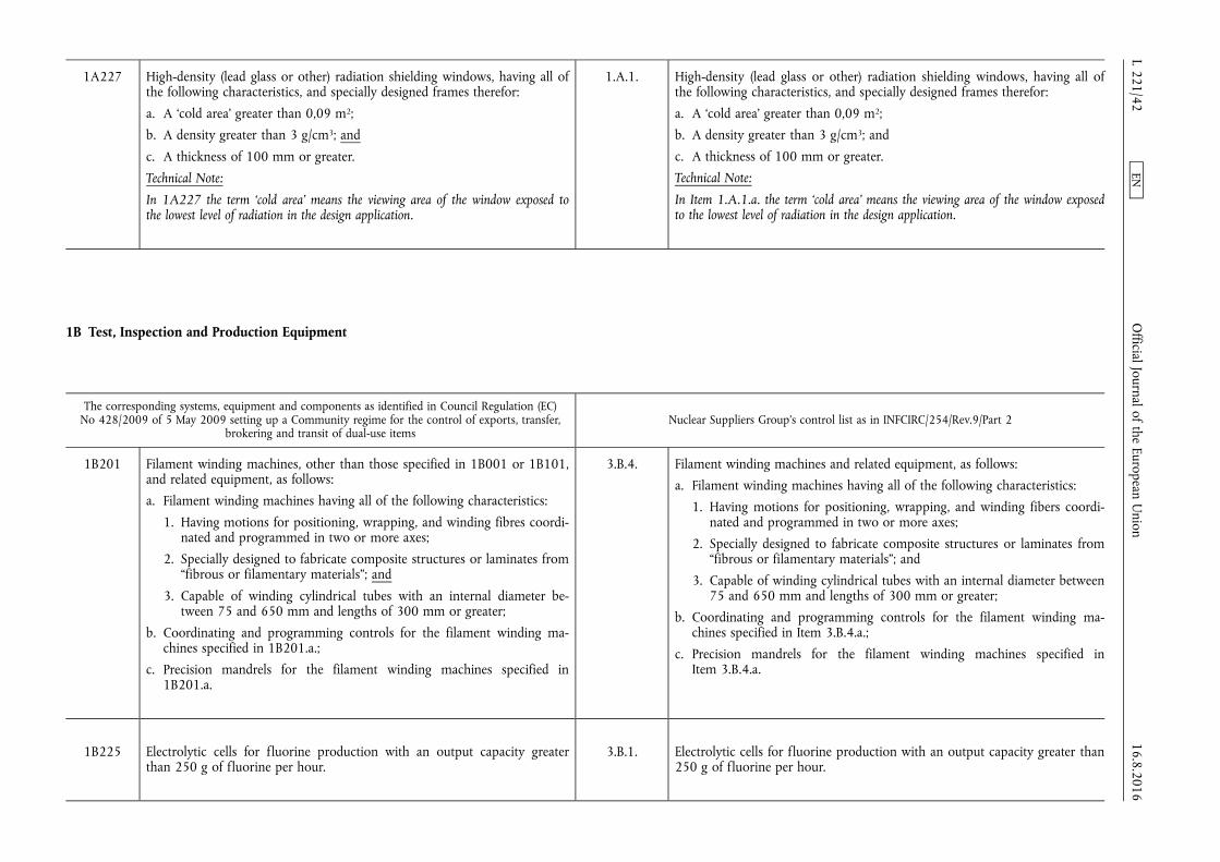
1A227 High-density (lead glass or other) radiation shielding windows, having all of the following characteristics, and specially designed frames therefor:
a. A ‘cold area’ greater than 0,09 m2;
b. A density greater than 3 g/cm3; and
c. A thickness of 100 mm or greater.
Technical Note:
In 1A227 the term ‘cold area’ means the viewing area of the window exposed to the lowest level of radiation in the design application.
1.A.1. High-density (lead glass or other) radiation shielding windows, having all of the following characteristics, and specially designed frames therefor:
a. A ‘cold area’ greater than 0,09 m2;
b. A density greater than 3 g/cm3; and
c. A thickness of 100 mm or greater.
Technical Note:
In Item 1.A.1.a. the term ‘cold area’ means the viewing area of the window exposed to the lowest level of radiation in the design application.
1B Test, Inspection and Production Equipment
The corresponding systems, equipment and components as identified in Council Regulation (EC) No 428/2009 of 5 May 2009 setting up a Community regime for the control of exports, transfer,
brokering and transit of dual-use items Nuclear Suppliers Group's control list as in INFCIRC/254/Rev.9/Part 2
1B201 Filament winding machines, other than those specified in 1B001 or 1B101, and related equipment, as follows:
a. Filament winding machines having all of the following characteristics:
1. Having motions for positioning, wrapping, and winding fibres coordinated and programmed in two or more axes;
2. Specially designed to fabricate composite structures or laminates from “fibrous or filamentary materials”; and
3. Capable of winding cylindrical tubes with an internal diameter between 75 and 650 mm and lengths of 300 mm or greater;
b. Coordinating and programming controls for the filament winding machines specified in 1B201.a.;
c. Precision mandrels for the filament winding machines specified in 1B201.a.
3.B.4. Filament winding machines and related equipment, as follows:
a. Filament winding machines having all of the following characteristics:
1. Having motions for positioning, wrapping, and winding fibers coordinated and programmed in two or more axes;
2. Specially designed to fabricate composite structures or laminates from “fibrous or filamentary materials”; and
3. Capable of winding cylindrical tubes with an internal diameter between 75 and 650 mm and lengths of 300 mm or greater;
b. Coordinating and programming controls for the filament winding machines specified in Item 3.B.4.a.;
c. Precision mandrels for the filament winding machines specified in Item 3.B.4.a.
1B225 Electrolytic cells for fluorine production with an output capacity greater than 250 g of fluorine per hour.
3.B.1. Electrolytic cells for fluorine production with an output capacity greater than 250 g of fluorine per hour.
16.8.2016 L 221/42
Official Journal of the European U
nion EN

1B226 Electromagnetic isotope separators designed for, or equipped with, single or multiple ion sources capable of providing a total ion beam current of 50 mA or greater.
Note: 1B226 includes separators:
a. Capable of enriching stable isotopes;
b. With the ion sources and collectors both in the magnetic field and those configurations in which they are external to the field.
3.B.5. Electromagnetic isotope separators designed for, or equipped with, single or multiple ion sources capable of providing a total ion beam current of 50 mA or greater.
Notes:
1. Item 3.B.5. includes separators capable of enriching stable isotopes as well as those for uranium.
N.B.: A separator capable of separating the isotopes of lead with a one-mass unit difference is inherently capable of enriching the isotopes of uranium with a three-unit mass difference.
2. Item 3.B.5. includes separators with the ion sources and collectors both in the magnetic field and those configurations in which they are external to the field.
Technical Note:
A single 50 mA ion source cannot produce more than 3 g of separated highly enriched uranium (HEU) per year from natural abundance feed.
1B228 Hydrogen-cryogenic distillation columns having all of the following characteristics:
a. Designed for operation with internal temperatures of 35 K (–238 °C) or less;
b. Designed for operation at an internal pressure of 0,5 to 5 MPa;
c. Constructed of either:
1. Stainless steel of the 300 series with low sulphur content and with an austenitic ASTM (or equivalent standard) grain size number of 5 or greater; or
2. Equivalent materials which are both cryogenic and H2-compatible; and
d. With internal diameters of 30 cm or greater and ‘effective lengths’ of 4 m or greater.
Technical Note:
In 1B228 ‘effective length’ means the active height of packing material in a packed- type column, or the active height of internal contactor plates in a plate-type column.
4.B.2. Hydrogen-cryogenic distillation columns having all of the following characteristics:
a. Designed for operation at internal temperatures of 35 K (–238 °C) or less;
b. Designed for operation at internal pressures of 0,5 to 5 MPa;
c. Constructed of either:
1. Stainless steel of the 300 series with low sulfur content and with an austenitic ASTM (or equivalent standard) grain size number of 5 or greater; or
2. Equivalent materials which are both cryogenic and H2-compatible; and
d. With internal diameters of 30 cm or greater and ‘effective lengths’ of 4 m or greater.
Technical Note:
The term ‘effective length’ means the active height of packing material in a packed- type column, or the active height of internal contactor plates in a plate-type column.
16.8.2016 L 221/43
Official Journal of the European U
nion EN

1B229 Water-hydrogen sulphide exchange tray columns and ‘internal contactors’, as follows:
N.B.: For columns which are specially designed or prepared for the production of heavy water see 0B004.
a. Water-hydrogen sulphide exchange tray columns, having all of the following characteristics:
1. Can operate at pressures of 2 MPa or greater;
2. Constructed of carbon steel having an austenitic ASTM (or equivalent standard) grain size number of 5 or greater; and
3. With a diameter of 1,8 m or greater;
b. ‘Internal contactors’ for the water-hydrogen sulphide exchange tray columns specified in 1B229.a.
Technical Note:
‘Internal contactors’ of the columns are segmented trays which have an effective assembled diameter of 1,8 m or greater, are designed to facilitate countercurrent contacting and are constructed of stainless steels with a carbon content of 0,03 % or less. These may be sieve trays, valve trays, bubble cap trays, or turbogrid trays.
4.B.1. Water-hydrogen sulfide exchange tray columns and internal contactors, as follows:
N.B.: For columns which are especially designed or prepared for the production of heavy water, see INFCIRC/254/Part 1 (as amended).
a. Water-hydrogen sulfide exchange tray columns, having all of the following characteristics:
1. Can operate at pressures of 2 MPa or greater;
2. Constructed of carbon steel having an austenitic ASTM (or equivalent standard) grain size number of 5 or greater; and
3. With a diameter of 1,8 m or greater;
b. Internal contactors for the water-hydrogen sulfide exchange tray columns specified in Item 4.B.1.a.
Technical Note:
Internal contactors of the columns are segmented trays which have an effective assembled diameter of 1,8 m or greater; are designed to facilitate countercurrent contacting and are constructed of stainless steels with a carbon content of 0,03 % or less. These may be sieve trays, valve trays, bubble cap trays or turbogrid trays.
1B230 Pumps capable of circulating solutions of concentrated or dilute potassium amide catalyst in liquid ammonia (KNH2/NH3), having all of the following characteristics:
a. Airtight (i.e., hermetically sealed);
b. A capacity greater than 8,5 m3/h; and
c. Either of the following characteristics:
1. For concentrated potassium amide solutions (1 % or greater), an operating pressure of 1,5 to 60 MPa; or
2. For dilute potassium amide solutions (less than 1 %), an operating pressure of 20 to 60 MPa.
4.A.2. Pumps capable of circulating solutions of concentrated or dilute potassium amide catalyst in liquid ammonia (KNH2/NH3), having all of the following characteristics:
a. Airtight (i.e., hermetically sealed);
b. A capacity greater than 8,5 m3/h; and
c. Either of the following characteristics:
1. For concentrated potassium amide solutions (1 % or greater), an operating pressure of 1,5 to 60 MPa; or
2. For dilute potassium amide solutions (less than 1 %), an operating pressure of 20 to 60 MPa.
16.8.2016 L 221/44
Official Journal of the European U
nion EN
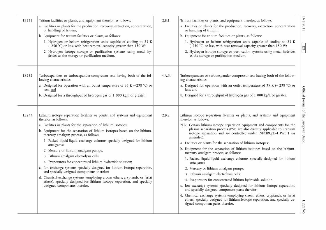
1B231 Tritium facilities or plants, and equipment therefor, as follows:
a. Facilities or plants for the production, recovery, extraction, concentration, or handling of tritium;
b. Equipment for tritium facilities or plants, as follows:
1. Hydrogen or helium refrigeration units capable of cooling to 23 K (–250 °C) or less, with heat removal capacity greater than 150 W;
2. Hydrogen isotope storage or purification systems using metal hydrides as the storage or purification medium.
2.B.1. Tritium facilities or plants, and equipment therefor, as follows:
a. Facilities or plants for the production, recovery, extraction, concentration or handling of tritium;
b. Equipment for tritium facilities or plants, as follows:
1. Hydrogen or helium refrigeration units capable of cooling to 23 K (–250 °C) or less, with heat removal capacity greater than 150 W;
2. Hydrogen isotope storage or purification systems using metal hydrides as the storage or purification medium.
1B232 Turboexpanders or turboexpander-compressor sets having both of the following characteristics:
a. Designed for operation with an outlet temperature of 35 K (–238 °C) or less; and
b. Designed for a throughput of hydrogen gas of 1 000 kg/h or greater.
4.A.3. Turboexpanders or turboexpander-compressor sets having both of the following characteristics:
a. Designed for operation with an outlet temperature of 35 K (– 238 °C) or less; and
b. Designed for a throughput of hydrogen gas of 1 000 kg/h or greater.
1B233 Lithium isotope separation facilities or plants, and systems and equipment therefor, as follows:
a. Facilities or plants for the separation of lithium isotopes;
b. Equipment for the separation of lithium isotopes based on the lithium- mercury amalgam process, as follows:
1. Packed liquid-liquid exchange columns specially designed for lithium amalgams;
2. Mercury or lithium amalgam pumps;
3. Lithium amalgam electrolysis cells;
4. Evaporators for concentrated lithium hydroxide solution;
c. Ion exchange systems specially designed for lithium isotope separation, and specially designed components therefor;
d. Chemical exchange systems (employing crown ethers, cryptands, or lariat ethers), specially designed for lithium isotope separation, and specially designed components therefor.
2.B.2. Lithium isotope separation facilities or plants, and systems and equipment therefor, as follows:
N.B.: Certain lithium isotope separation equipment and components for the plasma separation process (PSP) are also directly applicable to uranium isotope separation and are controlled under INFCIRC/254 Part 1 (as amended).
a. Facilities or plants for the separation of lithium isotopes;
b. Equipment for the separation of lithium isotopes based on the lithium- mercury amalgam process, as follows:
1. Packed liquid-liquid exchange columns specially designed for lithium amalgams;
2. Mercury or lithium amalgam pumps;
3. Lithium amalgam electrolysis cells;
4. Evaporators for concentrated lithium hydroxide solution;
c. Ion exchange systems specially designed for lithium isotope separation, and specially designed component parts therefor;
d. Chemical exchange systems (employing crown ethers, cryptands, or lariat ethers) specially designed for lithium isotope separation, and specially designed component parts therefor.
16.8.2016 L 221/45
Official Journal of the European U
nion EN
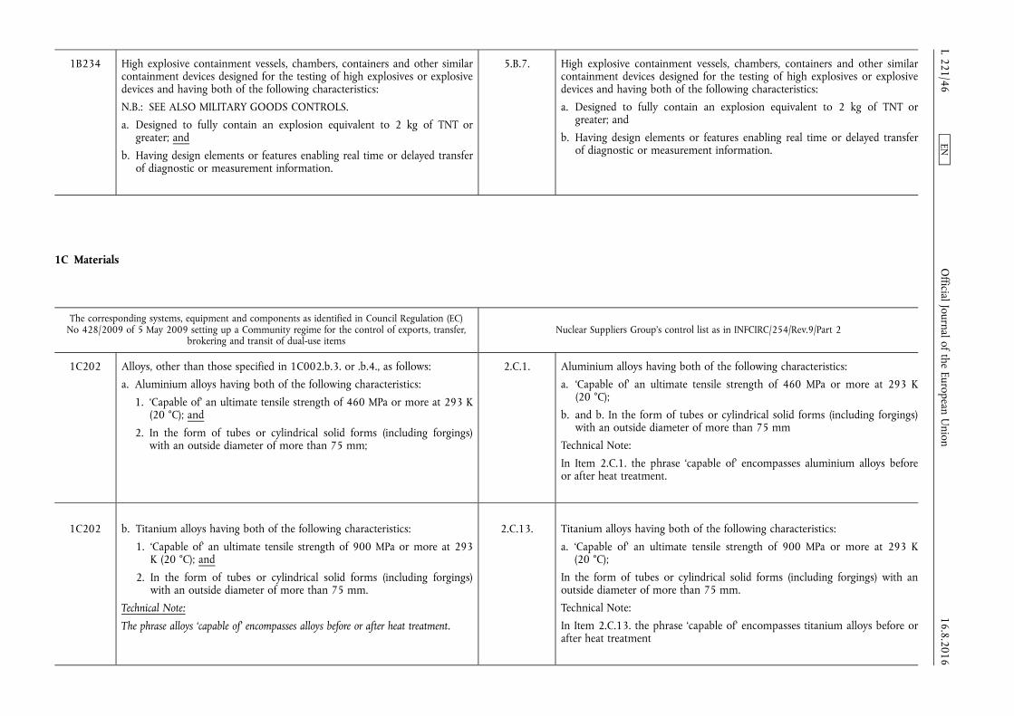
1B234 High explosive containment vessels, chambers, containers and other similar containment devices designed for the testing of high explosives or explosive devices and having both of the following characteristics:
N.B.: SEE ALSO MILITARY GOODS CONTROLS.
a. Designed to fully contain an explosion equivalent to 2 kg of TNT or greater; and
b. Having design elements or features enabling real time or delayed transfer of diagnostic or measurement information.
5.B.7. High explosive containment vessels, chambers, containers and other similar containment devices designed for the testing of high explosives or explosive devices and having both of the following characteristics:
a. Designed to fully contain an explosion equivalent to 2 kg of TNT or greater; and
b. Having design elements or features enabling real time or delayed transfer of diagnostic or measurement information.
1C Materials
The corresponding systems, equipment and components as identified in Council Regulation (EC) No 428/2009 of 5 May 2009 setting up a Community regime for the control of exports, transfer,
brokering and transit of dual-use items Nuclear Suppliers Group's control list as in INFCIRC/254/Rev.9/Part 2
1C202 Alloys, other than those specified in 1C002.b.3. or .b.4., as follows:
a. Aluminium alloys having both of the following characteristics:
1. ‘Capable of’ an ultimate tensile strength of 460 MPa or more at 293 K (20 °C); and
2. In the form of tubes or cylindrical solid forms (including forgings) with an outside diameter of more than 75 mm;
2.C.1. Aluminium alloys having both of the following characteristics:
a. ‘Capable of’ an ultimate tensile strength of 460 MPa or more at 293 K (20 °C);
b. and b. In the form of tubes or cylindrical solid forms (including forgings) with an outside diameter of more than 75 mm
Technical Note:
In Item 2.C.1. the phrase ‘capable of’ encompasses aluminium alloys before or after heat treatment.
1C202 b. Titanium alloys having both of the following characteristics:
1. ‘Capable of’ an ultimate tensile strength of 900 MPa or more at 293 K (20 °C); and
2. In the form of tubes or cylindrical solid forms (including forgings) with an outside diameter of more than 75 mm.
Technical Note:
The phrase alloys ‘capable of’ encompasses alloys before or after heat treatment.
2.C.13. Titanium alloys having both of the following characteristics:
a. ‘Capable of’ an ultimate tensile strength of 900 MPa or more at 293 K (20 °C);
In the form of tubes or cylindrical solid forms (including forgings) with an outside diameter of more than 75 mm.
Technical Note:
In Item 2.C.13. the phrase ‘capable of’ encompasses titanium alloys before or after heat treatment
16.8.2016 L 221/46
Official Journal of the European U
nion EN
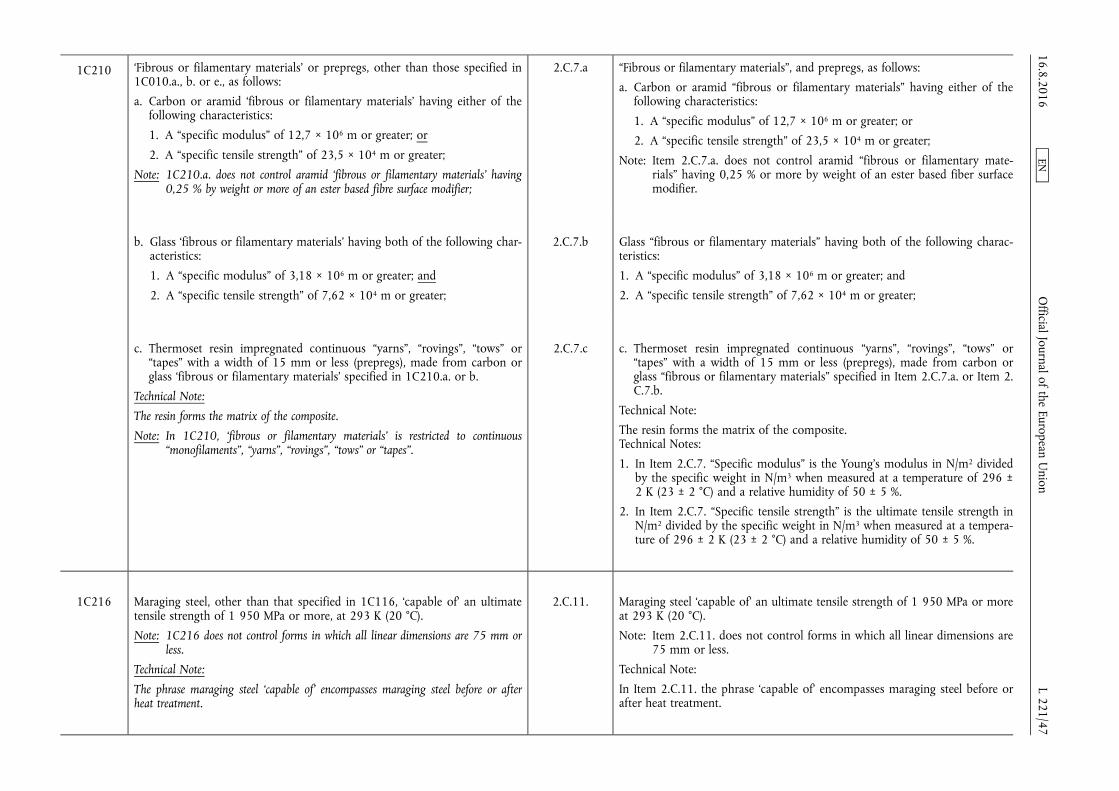
1C210 ‘Fibrous or filamentary materials’ or prepregs, other than those specified in 1C010.a., b. or e., as follows:
a. Carbon or aramid ‘fibrous or filamentary materials’ having either of the following characteristics:
1. A “specific modulus” of 12,7 × 10⁶ m or greater; or
2. A “specific tensile strength” of 23,5 × 10⁴ m or greater;
Note: 1C210.a. does not control aramid ‘fibrous or filamentary materials’ having 0,25 % by weight or more of an ester based fibre surface modifier;
2.C.7.a “Fibrous or filamentary materials”, and prepregs, as follows:
a. Carbon or aramid “fibrous or filamentary materials” having either of the following characteristics:
1. A “specific modulus” of 12,7 × 10⁶ m or greater; or
2. A “specific tensile strength” of 23,5 × 10⁴ m or greater;
Note: Item 2.C.7.a. does not control aramid “fibrous or filamentary materials” having 0,25 % or more by weight of an ester based fiber surface modifier.
b. Glass ‘fibrous or filamentary materials’ having both of the following characteristics:
1. A “specific modulus” of 3,18 × 10⁶ m or greater; and
2. A “specific tensile strength” of 7,62 × 10⁴ m or greater;
2.C.7.b Glass “fibrous or filamentary materials” having both of the following characteristics:
1. A “specific modulus” of 3,18 × 10⁶ m or greater; and
2. A “specific tensile strength” of 7,62 × 10⁴ m or greater;
c. Thermoset resin impregnated continuous “yarns”, “rovings”, “tows” or “tapes” with a width of 15 mm or less (prepregs), made from carbon or glass ‘fibrous or filamentary materials’ specified in 1C210.a. or b.
Technical Note:
The resin forms the matrix of the composite.
Note: In 1C210, ‘fibrous or filamentary materials’ is restricted to continuous “monofilaments”, “yarns”, “rovings”, “tows” or “tapes”.
2.C.7.c c. Thermoset resin impregnated continuous “yarns”, “rovings”, “tows” or “tapes” with a width of 15 mm or less (prepregs), made from carbon or glass “fibrous or filamentary materials” specified in Item 2.C.7.a. or Item 2. C.7.b.
Technical Note:
The resin forms the matrix of the composite. Technical Notes:
1. In Item 2.C.7. “Specific modulus” is the Young's modulus in N/m2 divided by the specific weight in N/m3 when measured at a temperature of 296 ± 2 K (23 ± 2 °C) and a relative humidity of 50 ± 5 %.
2. In Item 2.C.7. “Specific tensile strength” is the ultimate tensile strength in N/m2 divided by the specific weight in N/m3 when measured at a temperature of 296 ± 2 K (23 ± 2 °C) and a relative humidity of 50 ± 5 %.
1C216 Maraging steel, other than that specified in 1C116, ‘capable of’ an ultimate tensile strength of 1 950 MPa or more, at 293 K (20 °C).
Note: 1C216 does not control forms in which all linear dimensions are 75 mm or less.
Technical Note:
The phrase maraging steel ‘capable of’ encompasses maraging steel before or after heat treatment.
2.C.11. Maraging steel ‘capable of’ an ultimate tensile strength of 1 950 MPa or more at 293 K (20 °C).
Note: Item 2.C.11. does not control forms in which all linear dimensions are 75 mm or less.
Technical Note:
In Item 2.C.11. the phrase ‘capable of’ encompasses maraging steel before or after heat treatment.
16.8.2016 L 221/47
Official Journal of the European U
nion EN

1C225 Boron enriched in the boron-10 (10B) isotope to greater than its natural isotopic abundance, as follows: elemental boron, compounds, mixtures containing boron, manufactures thereof, waste or scrap of any of the foregoing.
Note: In 1C225 mixtures containing boron include boron loaded materials.
Technical Note:
The natural isotopic abundance of boron-10 is approximately 18,5 weight per cent (20 atom per cent).
2.C.4. Boron enriched in the boron-10 (10B) isotope to greater than its natural isotopic abundance, as follows: elemental boron, compounds, mixtures containing boron, manufactures thereof, waste or scrap of any of the foregoing.
Note: In Item 2.C.4. mixtures containing boron include boron loaded materials.
Technical Note:
The natural isotopic abundance of boron-10 is approximately 18,5 weight percent (20 atom percent).
1C226 Tungsten, tungsten carbide, and alloys containing more than 90 % tungsten by weight, other than that specified by 1C117, having both of the following characteristics:
a. In forms with a hollow cylindrical symmetry (including cylinder segments) with an inside diameter between 100 mm and 300 mm; and
b. A mass greater than 20 kg.
Note: 1C226 does not control manufactures specially designed as weights or gamma-ray collimators.
2.C.14. Tungsten, tungsten carbide, and alloys containing more than 90 % tungsten by weight, having both of the following characteristics:
a. In forms with a hollow cylindrical symmetry (including cylinder segments) with an inside diameter between 100 and 300 mm; and
b. A mass greater than 20 kg.
Note: Item 2.C.14. does not control manufactures specially designed as weights or gamma-ray collimators.
1C227 Calcium having both of the following characteristics:
a. Containing less than 1 000 parts per million by weight of metallic impurities other than magnesium; and
b. Containing less than 10 parts per million by weight of boron.
2.C.5. Calcium having both of the following characteristics:
a. Containing less than 1 000 parts per million by weight of metallic impurities other than magnesium; and
b. Containing less than 10 parts per million by weight of boron.
1C228 Magnesium having both of the following characteristics:
a. Containing less than 200 parts per million by weight of metallic impurities other than calcium; and
b. Containing less than 10 parts per million by weight of boron.
2.C.10. Magnesium having both of the following characteristics:
a. Containing less than 200 parts per million by weight of metallic impurities other than calcium; and
b. Containing less than 10 parts per million by weight of boron.
1C229 Bismuth having both of the following characteristics:
a. A purity of 99,99 % or greater by weight; and
b. Containing less than 10 ppm (parts per million) by weight of silver.
2.C.3. Bismuth having both of the following characteristics:
a. A purity of 99,99 % or greater by weight; and
b. Containing less than 10 ppm (parts per million) by weight of silver.
16.8.2016 L 221/48
Official Journal of the European U
nion EN
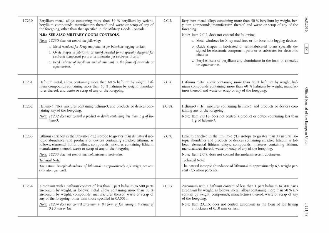
1C230 Beryllium metal, alloys containing more than 50 % beryllium by weight, beryllium compounds, manufactures thereof, and waste or scrap of any of the foregoing, other than that specified in the Military Goods Controls.
N.B.: SEE ALSO MILITARY GOODS CONTROLS. Note: 1C230 does not control the following:
a. Metal windows for X-ray machines, or for bore-hole logging devices;
b. Oxide shapes in fabricated or semi-fabricated forms specially designed for electronic component parts or as substrates for electronic circuits;
c. Beryl (silicate of beryllium and aluminium) in the form of emeralds or aquamarines.
2.C.2. Beryllium metal, alloys containing more than 50 % beryllium by weight, beryllium compounds, manufactures thereof, and waste or scrap of any of the foregoing.
Note: Item 2.C.2. does not control the following:
a. Metal windows for X-ray machines or for bore-hole logging devices;
b. Oxide shapes in fabricated or semi-fabricated forms specially designed for electronic component parts or as substrates for electronic circuits;
c. Beryl (silicate of beryllium and aluminium) in the form of emeralds or aquamarines.
1C231 Hafnium metal, alloys containing more than 60 % hafnium by weight, hafnium compounds containing more than 60 % hafnium by weight, manufactures thereof, and waste or scrap of any of the foregoing.
2.C.8. Hafnium metal, alloys containing more than 60 % hafnium by weight, hafnium compounds containing more than 60 % hafnium by weight, manufactures thereof, and waste or scrap of any of the foregoing.
1C232 Helium-3 (3He), mixtures containing helium-3, and products or devices containing any of the foregoing.
Note: 1C232 does not control a product or device containing less than 1 g of helium-3.
2.C.18. Helium-3 (3He), mixtures containing helium-3, and products or devices containing any of the foregoing.
Note: Item 2.C.18. does not control a product or device containing less than 1 g of helium-3.
1C233 Lithium enriched in the lithium-6 (6Li) isotope to greater than its natural isotopic abundance, and products or devices containing enriched lithium, as follows: elemental lithium, alloys, compounds, mixtures containing lithium, manufactures thereof, waste or scrap of any of the foregoing.
Note: 1C233 does not control thermoluminescent dosimeters.
Technical Note:
The natural isotopic abundance of lithium-6 is approximately 6,5 weight per cent (7,5 atom per cent).
2.C.9. Lithium enriched in the lithium-6 (6Li) isotope to greater than its natural isotopic abundance and products or devices containing enriched lithium, as follows: elemental lithium, alloys, compounds, mixtures containing lithium, manufactures thereof, waste or scrap of any of the foregoing.
Note: Item 2.C.9. does not control thermoluminescent dosimeters.
Technical Note:
The natural isotopic abundance of lithium-6 is approximately 6,5 weight percent (7,5 atom percent).
1C234 Zirconium with a hafnium content of less than 1 part hafnium to 500 parts zirconium by weight, as follows: metal, alloys containing more than 50 % zirconium by weight, compounds, manufactures thereof, waste or scrap of any of the foregoing, other than those specified in 0A001.f.
Note: 1C234 does not control zirconium in the form of foil having a thickness of 0,10 mm or less.
2.C.15. Zirconium with a hafnium content of less than 1 part hafnium to 500 parts zirconium by weight, as follows: metal, alloys containing more than 50 % zirconium by weight, compounds, manufactures thereof, waste or scrap of any of the foregoing.
Note: Item 2.C.15. does not control zirconium in the form of foil having a thickness of 0,10 mm or less.
16.8.2016 L 221/49
Official Journal of the European U
nion EN

1C235 Tritium, tritium compounds, mixtures containing tritium in which the ratio of tritium to hydrogen atoms exceeds 1 part in 1 000, and products or devices containing any of the foregoing.
Note: 1C235 does not control a product or device containing less than 1,48 × 10³ GBq (40 Ci) of tritium.
2.C.17. Tritium, tritium compounds, mixtures containing tritium in which the ratio of tritium to hydrogen atoms exceeds 1 part in 1 000, and products or devices containing any of the foregoing.
Note: Item 2.C.17. does not control a product or device containing less than 1,48 × 10³ GBq of tritium.
1C236 ‘Radionuclides’ appropriate for making neutron sources based on alpha-n reaction, other than those specified in 0C001 and 1C012.a., in the following forms:
a. Elemental;
b. Compounds having a total activity of 37 GBq/kg (1 Ci/kg) or greater;
c. Mixtures having a total activity of 37 GBq/kg (1 Ci/kg) or greater;
d. Products or devices containing any of the foregoing.
Note: 1C236 does not control a product or device containing less than 3,7 GBq (100 millicuries) of activity.
Technical Note:
In 1C236 ‘radionuclides’ are any of the following:
— Actinium-225 (Ac-225)
— Actinium-227 (Ac-227)
— Californium-253 (Cf-253)
— Curium-240 (Cm-240)
— Curium-241 (Cm-241)
— Curium-242 (Cm-242)
— Curium-243 (Cm-243)
— Curium-244 (Cm-244)
— Einsteinium-253 (Es-253)
— Einsteinium-254 (Es-254)
— Gadolinium-148 (Gd-148)
2.C.19. Radionuclides appropriate for making neutron sources based on alpha-n reaction:
Actinium 225
Curium 244
Polonium 209
Actinium 227
Einsteinium 253
Polonium 210
Californium 253
Einsteinium 254
Radium 223
Curium 240
Gadolinium 148
Thorium 227
Curium 241
Plutonium 236
Thorium 228
Curium 242
Plutonium 238
Uranium 230
Curium 243
Polonium 208
Uranium 232
16.8.2016 L 221/50
Official Journal of the European U
nion EN
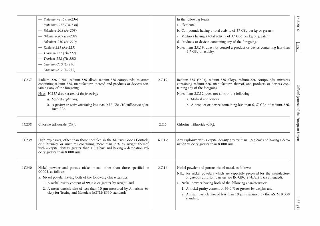
— Plutonium-236 (Pu-236)
— Plutonium-238 (Pu-238)
— Polonium-208 (Po-208)
— Polonium-209 (Po-209)
— Polonium-210 (Po-210)
— Radium-223 (Ra-223)
— Thorium-227 (Th-227)
— Thorium-228 (Th-228)
— Uranium-230 (U-230)
— Uranium-232 (U-232)
In the following forms:
a. Elemental;
b. Compounds having a total activity of 37 GBq per kg or greater;
c. Mixtures having a total activity of 37 GBq per kg or greater;
d. Products or devices containing any of the foregoing.
Note: Item 2.C.19. does not control a product or device containing less than 3,7 GBq of activity.
1C237 Radium 226 (226Ra), radium-226 alloys, radium-226 compounds, mixtures containing radium 226, manufactures thereof, and products or devices containing any of the foregoing.
Note: 1C237 does not control the following:
a. Medical applicators;
b. A product or device containing less than 0,37 GBq (10 millicuries) of radium 226.
2.C.12. Radium-226 (226Ra), radium-226 alloys, radium-226 compounds, mixtures containing radium-226, manufactures thereof, and products or devices containing any of the foregoing.
Note: Item 2.C.12. does not control the following:
a. Medical applicators;
b. A product or device containing less than 0,37 GBq of radium-226.
1C238 Chlorine trifluoride (ClF3). 2.C.6. Chlorine trifluoride (ClF3).
1C239 High explosives, other than those specified in the Military Goods Controls, or substances or mixtures containing more than 2 % by weight thereof, with a crystal density greater than 1,8 g/cm3 and having a detonation velocity greater than 8 000 m/s.
6.C.1.o Any explosive with a crystal density greater than 1,8 g/cm3 and having a detonation velocity greater than 8 000 m/s.
1C240 Nickel powder and porous nickel metal, other than those specified in 0C005, as follows:
a. Nickel powder having both of the following characteristics:
1. A nickel purity content of 99,0 % or greater by weight; and
2. A mean particle size of less than 10 µm measured by American Society for Testing and Materials (ASTM) B330 standard;
2.C.16. Nickel powder and porous nickel metal, as follows:
N.B.: For nickel powders which are especially prepared for the manufacture of gaseous diffusion barriers see INFCIRC/254/Part 1 (as amended).
a. Nickel powder having both of the following characteristics:
1. A nickel purity content of 99,0 % or greater by weight; and
2. A mean particle size of less than 10 µm measured by the ASTM B 330 standard;
16.8.2016 L 221/51
Official Journal of the European U
nion EN
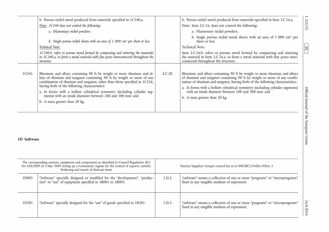
b. Porous nickel metal produced from materials specified in 1C240.a.
Note: 1C240 does not control the following:
a. Filamentary nickel powders;
b. Single porous nickel sheets with an area of 1 000 cm2 per sheet or less.
Technical Note:
1C240.b. refers to porous metal formed by compacting and sintering the materials in 1C240.a. to form a metal material with fine pores interconnected throughout the structure.
b. Porous nickel metal produced from materials specified in Item 2.C.16.a.
Note: Item 2.C.16. does not control the following:
a. Filamentary nickel powders;
b. Single porous nickel metal sheets with an area of 1 000 cm2 per sheet or less.
Technical Note:
Item 2.C.16.b. refers to porous metal formed by compacting and sintering the material in Item 2.C.16.a. to form a metal material with fine pores interconnected throughout the structure.
1C241 Rhenium, and alloys containing 90 % by weight or more rhenium; and alloys of rhenium and tungsten containing 90 % by weight or more of any combination of rhenium and tungsten, other than those specified in 1C226, having both of the following characteristics:
a. In forms with a hollow cylindrical symmetry (including cylinder segments) with an inside diameter between 100 and 300 mm; and
b. A mass greater than 20 kg.
2.C.20. Rhenium, and alloys containing 90 % by weight or more rhenium; and alloys of rhenium and tungsten containing 90 % by weight or more of any combination of rhenium and tungsten, having both of the following characteristics:
a. In forms with a hollow cylindrical symmetry (including cylinder segments) with an inside diameter between 100 and 300 mm; and
b. A mass greater than 20 kg.
1D Software
The corresponding systems, equipment and components as identified in Council Regulation (EC) No 428/2009 of 5 May 2009 setting up a Community regime for the control of exports, transfer,
brokering and transit of dual-use items Nuclear Suppliers Group's control list as in INFCIRC/254/Rev.9/Part 2
1D001 “Software” specially designed or modified for the “development”, “production” or “use” of equipment specified in 1B001 to 1B003.
1.D.2. “software” means a collection of one or more “programs” or “microprograms” fixed in any tangible medium of expression
1D201 “Software” specially designed for the “use” of goods specified in 1B201. 1.D.3. “software” means a collection of one or more “programs” or “microprograms” fixed in any tangible medium of expression
16.8.2016 L 221/52
Official Journal of the European U
nion EN
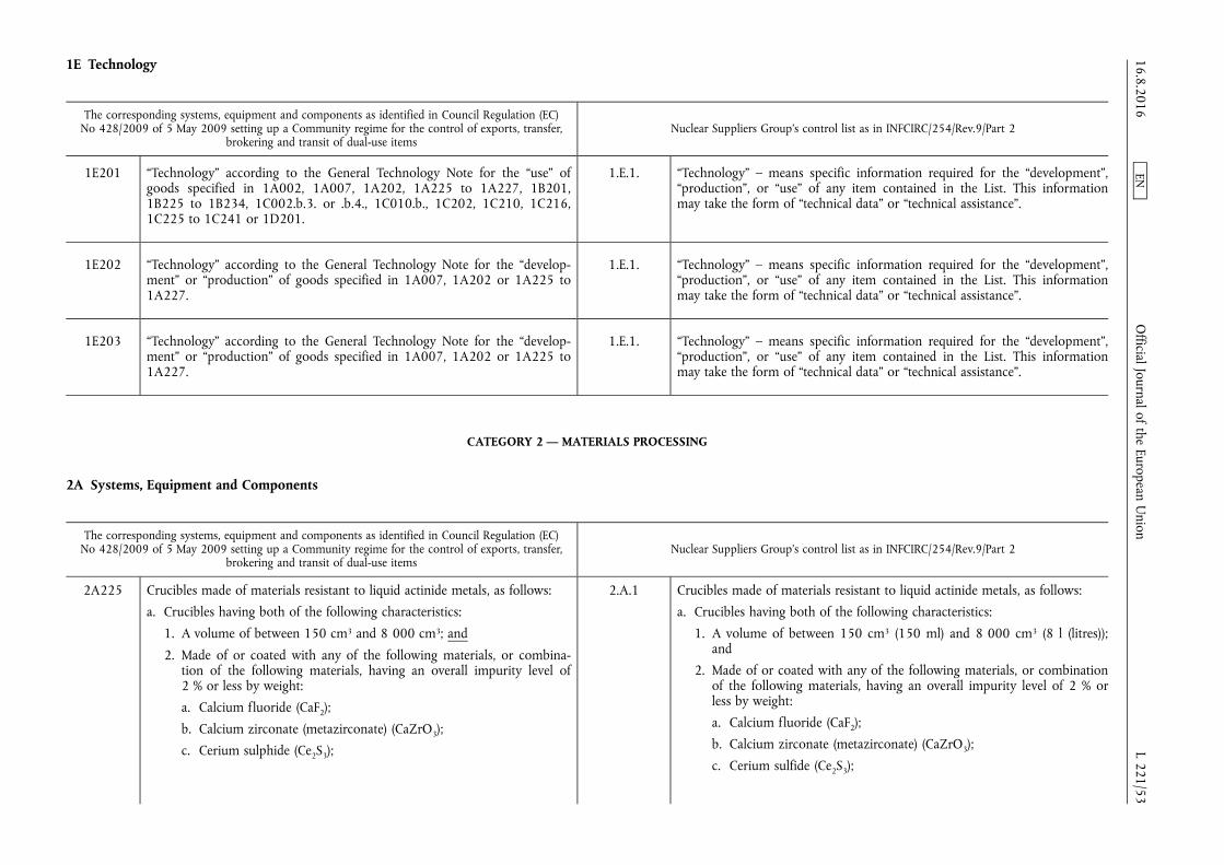
1E Technology
The corresponding systems, equipment and components as identified in Council Regulation (EC) No 428/2009 of 5 May 2009 setting up a Community regime for the control of exports, transfer,
brokering and transit of dual-use items Nuclear Suppliers Group's control list as in INFCIRC/254/Rev.9/Part 2
1E201 “Technology” according to the General Technology Note for the “use” of goods specified in 1A002, 1A007, 1A202, 1A225 to 1A227, 1B201, 1B225 to 1B234, 1C002.b.3. or .b.4., 1C010.b., 1C202, 1C210, 1C216, 1C225 to 1C241 or 1D201.
1.E.1. “Technology” – means specific information required for the “development”, “production”, or “use” of any item contained in the List. This information may take the form of “technical data” or “technical assistance”.
1E202 “Technology” according to the General Technology Note for the “development” or “production” of goods specified in 1A007, 1A202 or 1A225 to 1A227.
1.E.1. “Technology” – means specific information required for the “development”, “production”, or “use” of any item contained in the List. This information may take the form of “technical data” or “technical assistance”.
1E203 “Technology” according to the General Technology Note for the “development” or “production” of goods specified in 1A007, 1A202 or 1A225 to 1A227.
1.E.1. “Technology” – means specific information required for the “development”, “production”, or “use” of any item contained in the List. This information may take the form of “technical data” or “technical assistance”.
CATEGORY 2 — MATERIALS PROCESSING
2A Systems, Equipment and Components
The corresponding systems, equipment and components as identified in Council Regulation (EC) No 428/2009 of 5 May 2009 setting up a Community regime for the control of exports, transfer,
brokering and transit of dual-use items Nuclear Suppliers Group's control list as in INFCIRC/254/Rev.9/Part 2
2A225 Crucibles made of materials resistant to liquid actinide metals, as follows:
a. Crucibles having both of the following characteristics:
1. A volume of between 150 cm3 and 8 000 cm3; and
2. Made of or coated with any of the following materials, or combination of the following materials, having an overall impurity level of 2 % or less by weight:
a. Calcium fluoride (CaF2);
b. Calcium zirconate (metazirconate) (CaZrO3);
c. Cerium sulphide (Ce2S3);
2.A.1 Crucibles made of materials resistant to liquid actinide metals, as follows:
a. Crucibles having both of the following characteristics:
1. A volume of between 150 cm3 (150 ml) and 8 000 cm3 (8 l (litres)); and
2. Made of or coated with any of the following materials, or combination of the following materials, having an overall impurity level of 2 % or less by weight:
a. Calcium fluoride (CaF2);
b. Calcium zirconate (metazirconate) (CaZrO3);
c. Cerium sulfide (Ce2S3);
16.8.2016 L 221/53
Official Journal of the European U
nion EN

d. Erbium oxide (erbia) (Er2O3);
e. Hafnium oxide (hafnia) (HfO2);
f. Magnesium oxide (MgO);
g. Nitrided niobium-titanium-tungsten alloy (approximately 50 % Nb, 30 % Ti, 20 % W);
h. Yttrium oxide (yttria) (Y2O3); or
i. Zirconium oxide (zirconia) (ZrO2);
b. Crucibles having both of the following characteristics:
1. A volume of between 50 cm3 and 2 000 cm3; and
2. Made of or lined with tantalum, having a purity of 99,9 % or greater by weight;
c. Crucibles having all of the following characteristics:
1. A volume of between 50 cm3 and 2 000 cm3;
2. Made of or lined with tantalum, having a purity of 98 % or greater by weight; and
3. Coated with tantalum carbide, nitride, boride, or any combination thereof.
d. Erbium oxide (erbia) (Er2O3);
e. Hafnium oxide (hafnia) (HfO2);
f. Magnesium oxide (MgO);
g. Nitrided niobium-titanium-tungsten alloy (approximately 50 % Nb, 30 % Ti, 20 % W);
h. Yttrium oxide (yttria) (Y2O3); or
i. Zirconium oxide (zirconia) (ZrO2);
b. Crucibles having both of the following characteristics:
1. A volume of between 50 cm3 (50 ml) and 2 000 cm3 (2 liters); and
2. Made of or lined with tantalum, having a purity of 99,9 % or greater by weight;
c. Crucibles having all of the following characteristics:
1. A volume of between 50 cm3 (50 ml) and 2 000 cm3 (2 liters);
2. Made of or lined with tantalum, having a purity of 98 % or greater by weight; and
3. Coated with tantalum carbide, nitride, boride, or any combination thereof.
2A226 Valves having all of the following characteristics:
a. A ‘nominal size’ of 5 mm or greater;
b. Having a bellows seal; and
c. Wholly made of or lined with aluminium, aluminium alloy, nickel, or nickel alloy containing more than 60 % nickel by weight.
Technical Note:
For valves with different inlet and outlet diameters, the ‘nominal size’ in 2A226 refers to the smallest diameter.
3.A.3. Valves having all of the following characteristics:
a. A nominal size of 5 mm or greater;
b. Having a bellows seal; and
c. Wholly made of or lined with aluminium, aluminium alloy, nickel, or nickel alloy containing more than 60 % nickel by weight.
Technical Note:
For valves with different inlet and outlet diameter, the nominal size parameter in Item 3.A.3.a. refers to the smallest diameter.
16.8.2016 L 221/54
Official Journal of the European U
nion EN
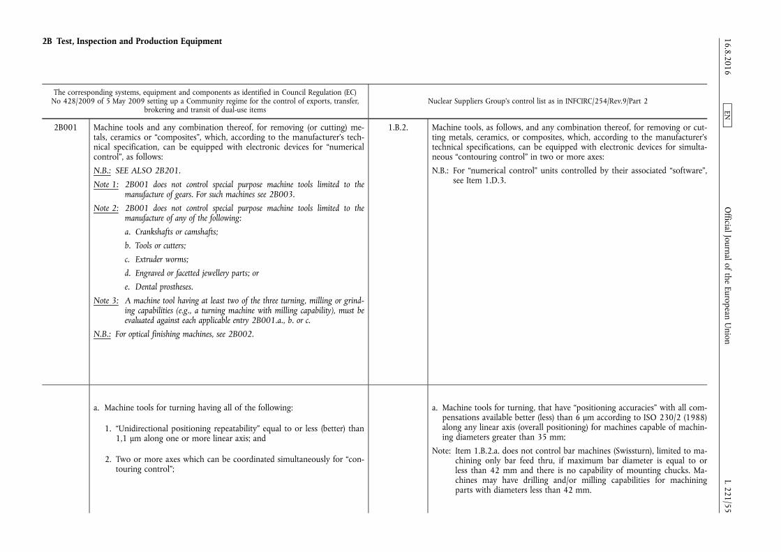
2B Test, Inspection and Production Equipment
The corresponding systems, equipment and components as identified in Council Regulation (EC) No 428/2009 of 5 May 2009 setting up a Community regime for the control of exports, transfer,
brokering and transit of dual-use items Nuclear Suppliers Group's control list as in INFCIRC/254/Rev.9/Part 2
2B001 Machine tools and any combination thereof, for removing (or cutting) metals, ceramics or “composites”, which, according to the manufacturer's technical specification, can be equipped with electronic devices for “numerical control”, as follows:
N.B.: SEE ALSO 2B201.
Note 1: 2B001 does not control special purpose machine tools limited to the manufacture of gears. For such machines see 2B003.
Note 2: 2B001 does not control special purpose machine tools limited to the manufacture of any of the following:
a. Crankshafts or camshafts;
b. Tools or cutters;
c. Extruder worms;
d. Engraved or facetted jewellery parts; or
e. Dental prostheses.
Note 3: A machine tool having at least two of the three turning, milling or grinding capabilities (e.g., a turning machine with milling capability), must be evaluated against each applicable entry 2B001.a., b. or c.
N.B.: For optical finishing machines, see 2B002.
1.B.2. Machine tools, as follows, and any combination thereof, for removing or cutting metals, ceramics, or composites, which, according to the manufacturer's technical specifications, can be equipped with electronic devices for simultaneous “contouring control” in two or more axes:
N.B.: For “numerical control” units controlled by their associated “software”, see Item 1.D.3.
a. Machine tools for turning having all of the following:
1. “Unidirectional positioning repeatability” equal to or less (better) than 1,1 µm along one or more linear axis; and
2. Two or more axes which can be coordinated simultaneously for “contouring control”;
a. Machine tools for turning, that have “positioning accuracies” with all compensations available better (less) than 6 μm according to ISO 230/2 (1988) along any linear axis (overall positioning) for machines capable of machining diameters greater than 35 mm;
Note: Item 1.B.2.a. does not control bar machines (Swissturn), limited to machining only bar feed thru, if maximum bar diameter is equal to or less than 42 mm and there is no capability of mounting chucks. Machines may have drilling and/or milling capabilities for machining parts with diameters less than 42 mm.
16.8.2016 L 221/55
Official Journal of the European U
nion EN

Note: 2B001.a. does not control turning machines specially designed for producing contact lenses, having all of the following:
a. Machine controller limited to using ophthalmic based software for part programming data input; and
b. No vacuum chucking.
b. Machine tools for milling having any of the following:
1. Having all of the following:
a. “Unidirectional positioning repeatability” equal to or less (better) than 1,1 µm along one or more linear axis; and
b. Three linear axes plus one rotary axis which can be coordinated simultaneously for “contouring control”;
2. Five or more axes which can be coordinated simultaneously for “contouring control” having any of the following;
N.B.: ‘Parallel mechanism machine tools’ are specified in 2B001.b.2.d.
a. “Unidirectional positioning repeatability” equal to or less (better) than 1,1 µm along one or more linear axis with a travel length less than 1 m;
b. “Unidirectional positioning repeatability” equal to or less (better) than 1,4 µm along one or more linear axis with a travel length equal to or greater than 1 m and less than 4 m;
c. “Unidirectional positioning repeatability” equal to or less (better) than 6,0 µm (along one or more linear axis with a travel length equal to or greater than 4 m; or
d. Being a ‘parallel mechanism machine tool’;
Technical Note:
A ‘parallel mechanism machine tool’ is a machine tool having multiple rods which are linked with a platform and actuators; each of the actuators operates the respective rod simultaneously and independently. 16.8.2016
L 221/56 O
fficial Journal of the European Union
EN

3. A “unidirectional positioning repeatability” for jig boring machines, equal to or less (better) than 1,1 µm along one or more linear axis; or
4. Fly cutting machines having all of the following:
a. Spindle “run-out” and “camming” less (better) than 0,0004 mm TIR; and
b. Angular deviation of slide movement (yaw, pitch and roll) less (better) than 2 seconds of arc, TIR over 300 mm of travel;
c. Machine tools for grinding having any of the following:
1. Having all of the following:
a. “Unidirectional positioning repeatability” equal to or less (better) than 1,1 µm along one or more linear axis; and
b. Three or more axes which can be coordinated simultaneously for “contouring control”; or
2. Five or more axes which can be coordinated simultaneously for “contouring control” having any of the following:
a. “Unidirectional positioning repeatability” equal to or less (better) than 1,1 µm along one or more linear axis with a travel length less than 1 m;
b. “Unidirectional positioning repeatability” equal to or less (better) than 1,4 µm along one or more linear axis with a travel length equal to or greater than 1 m and less than 4 m; or
c. “Unidirectional positioning repeatability” equal to or less (better) than 6,0 µm along one or more linear axis with a travel length equal to or greater than 4 m.
Note: 2B001.c. does not control grinding machine as follows:
a. Cylindrical external, internal, and external-internal grinding machines, having all of the following:
1. Limited to cylindrical grinding; and
2. Limited to a maximum workpiece capacity of 150 mm outside diameter or length.
16.8.2016 L 221/57
Official Journal of the European U
nion EN

b. Machines designed specifically as jig grinders that do not have a z- axis or a waxis, with a “unidirectional positioning repeatability” less (better) than 1,1 µm
c. Surface grinders.
d. Electrical discharge machines (EDM) of the non-wire type which have two or more rotary axes which can be coordinated simultaneously for “contouring control”;
e. Machine tools for removing metals, ceramics or “composites”, having all of the following:
1. Removing material by means of any of the following:
a. Water or other liquid jets, including those employing abrasive additives;
b. Electron beam; or
c. “Laser” beam; and
2. At least two rotary axes having all of the following:
a. Can be coordinated simultaneously for “contouring control”; and
b. A positioning “accuracy” of less (better) than 0,003°;
f. Deep-hole-drilling machines and turning machines modified for deep- hole-drilling, having a maximum depth-of-bore capability exceeding 5 m.
2B006 Dimensional inspection or measuring systems, equipment and “electronic assemblies”, as follows:
1.B.3.
2B006.b. Linear and angular displacement measuring instruments, as follows: 1.B.3. 1.B.3. Dimensional inspection machines, instruments, or systems, as follows:
2B006.b. 1. ‘Linear displacement’ measuring instruments having any of the following:
Note: Displacement measuring “laser” interferometers are only controlled in 2B006.b.1.c.
1.B.3.b. b. Linear displacement measuring instruments, as follows:
1. Non-contact type measuring systems with a “resolution” equal to or better (less) than 0,2 μm within a measuring range up to 0,2 mm; 16.8.2016
L 221/58 O
fficial Journal of the European Union
EN
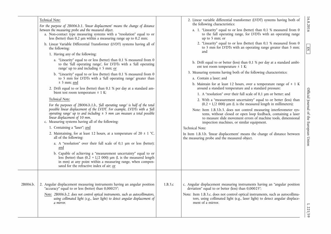
Technical Note:
For the purpose of 2B006.b.1. ‘linear displacement’ means the change of distance between the measuring probe and the measured object.
a. Non-contact type measuring systems with a “resolution” equal to or less (better) than 0,2 µm within a measuring range up to 0,2 mm;
b. Linear Variable Differential Transformer (LVDT) systems having all of the following:
1. Having any of the following:
a. “Linearity” equal to or less (better) than 0,1 % measured from 0 to the ‘full operating range’, for LVDTs with a ‘full operating range’ up to and including ± 5 mm; or
b. “Linearity” equal to or less (better) than 0,1 % measured from 0 to 5 mm for LVDTs with a ‘full operating range’ greater than ± 5 mm; and
2. Drift equal to or less (better) than 0,1 % per day at a standard ambient test room temperature ± 1 K;
Technical Note:
For the purposes of 2B006.b.1.b., ‘full operating range’ is half of the total possible linear displacement of the LVDT. For example, LVDTs with a ‘full operating range’ up to and including ± 5 mm can measure a total possible linear displacement of 10 mm.
c. Measuring systems having all of the following:
1. Containing a “laser”; and
2. Maintaining, for at least 12 hours, at a temperature of 20 ± 1 °C, all of the following:
a. A “resolution” over their full scale of 0,1 µm or less (better); and
b. Capable of achieving a “measurement uncertainty” equal to or less (better) than (0,2 + L/2 000) µm (L is the measured length in mm) at any point within a measuring range, when compensated for the refractive index of air; or
2. Linear variable differential transformer (LVDT) systems having both of the following characteristics:
a. 1. “Linearity” equal to or less (better) than 0,1 % measured from 0 to the full operating range, for LVDTs with an operating range up to 5 mm; or
2. “Linearity” equal to or less (better) than 0,1 % measured from 0 to 5 mm for LVDTs with an operating range greater than 5 mm; and
b. Drift equal to or better (less) than 0,1 % per day at a standard ambient test room temperature ± 1 K;
3. Measuring systems having both of the following characteristics:
a. Contain a laser; and
b. Maintain for at least 12 hours, over a temperature range of ± 1 K around a standard temperature and a standard pressure:
1. A “resolution” over their full scale of 0,1 μm or better; and
2. With a “measurement uncertainty” equal to or better (less) than (0,2 + L/2 000) μm (L is the measured length in millimeters);
Note: Item 1.B.3.b.3. does not control measuring interferometer systems, without closed or open loop feedback, containing a laser to measure slide movement errors of machine tools, dimensional inspection machines, or similar equipment.
Technical Note:
In Item 1.B.3.b. ‘linear displacement’ means the change of distance between the measuring probe and the measured object.
2B006.b. 2. Angular displacement measuring instruments having an angular position “accuracy” equal to or less (better) than 0,00025°;
Note: 2B006.b.2. does not control optical instruments, such as autocollimators, using collimated light (e.g., laser light) to detect angular displacement of a mirror.
1.B.3.c c. Angular displacement measuring instruments having an “angular position deviation” equal to or better (less) than 0,00025°;
Note: Item 1.B.3.c. does not control optical instruments, such as autocollimators, using collimated light (e.g., laser light) to detect angular displacement of a mirror.
16.8.2016 L 221/59
Official Journal of the European U
nion EN
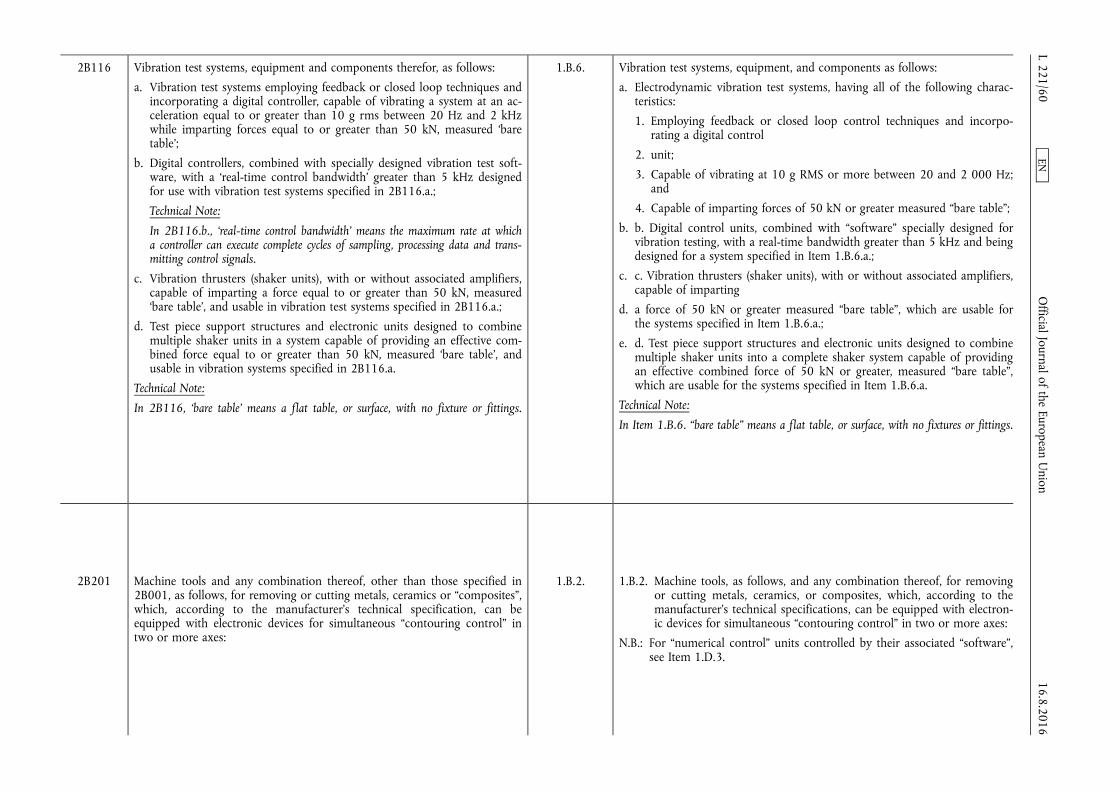
2B116 Vibration test systems, equipment and components therefor, as follows:
a. Vibration test systems employing feedback or closed loop techniques and incorporating a digital controller, capable of vibrating a system at an acceleration equal to or greater than 10 g rms between 20 Hz and 2 kHz while imparting forces equal to or greater than 50 kN, measured ‘bare table’;
b. Digital controllers, combined with specially designed vibration test software, with a ‘real-time control bandwidth’ greater than 5 kHz designed for use with vibration test systems specified in 2B116.a.;
Technical Note:
In 2B116.b., ‘real-time control bandwidth’ means the maximum rate at which a controller can execute complete cycles of sampling, processing data and transmitting control signals.
c. Vibration thrusters (shaker units), with or without associated amplifiers, capable of imparting a force equal to or greater than 50 kN, measured ‘bare table’, and usable in vibration test systems specified in 2B116.a.;
d. Test piece support structures and electronic units designed to combine multiple shaker units in a system capable of providing an effective combined force equal to or greater than 50 kN, measured ‘bare table’, and usable in vibration systems specified in 2B116.a.
Technical Note:
In 2B116, ‘bare table’ means a flat table, or surface, with no fixture or fittings.
1.B.6. Vibration test systems, equipment, and components as follows:
a. Electrodynamic vibration test systems, having all of the following characteristics:
1. Employing feedback or closed loop control techniques and incorporating a digital control
2. unit;
3. Capable of vibrating at 10 g RMS or more between 20 and 2 000 Hz; and
4. Capable of imparting forces of 50 kN or greater measured “bare table”;
b. b. Digital control units, combined with “software” specially designed for vibration testing, with a real-time bandwidth greater than 5 kHz and being designed for a system specified in Item 1.B.6.a.;
c. c. Vibration thrusters (shaker units), with or without associated amplifiers, capable of imparting
d. a force of 50 kN or greater measured “bare table”, which are usable for the systems specified in Item 1.B.6.a.;
e. d. Test piece support structures and electronic units designed to combine multiple shaker units into a complete shaker system capable of providing an effective combined force of 50 kN or greater, measured “bare table”, which are usable for the systems specified in Item 1.B.6.a.
Technical Note:
In Item 1.B.6. “bare table” means a flat table, or surface, with no fixtures or fittings.
2B201 Machine tools and any combination thereof, other than those specified in 2B001, as follows, for removing or cutting metals, ceramics or “composites”, which, according to the manufacturer's technical specification, can be equipped with electronic devices for simultaneous “contouring control” in two or more axes:
1.B.2. 1.B.2. Machine tools, as follows, and any combination thereof, for removing or cutting metals, ceramics, or composites, which, according to the manufacturer's technical specifications, can be equipped with electronic devices for simultaneous “contouring control” in two or more axes:
N.B.: For “numerical control” units controlled by their associated “software”, see Item 1.D.3.
16.8.2016 L 221/60
Official Journal of the European U
nion EN
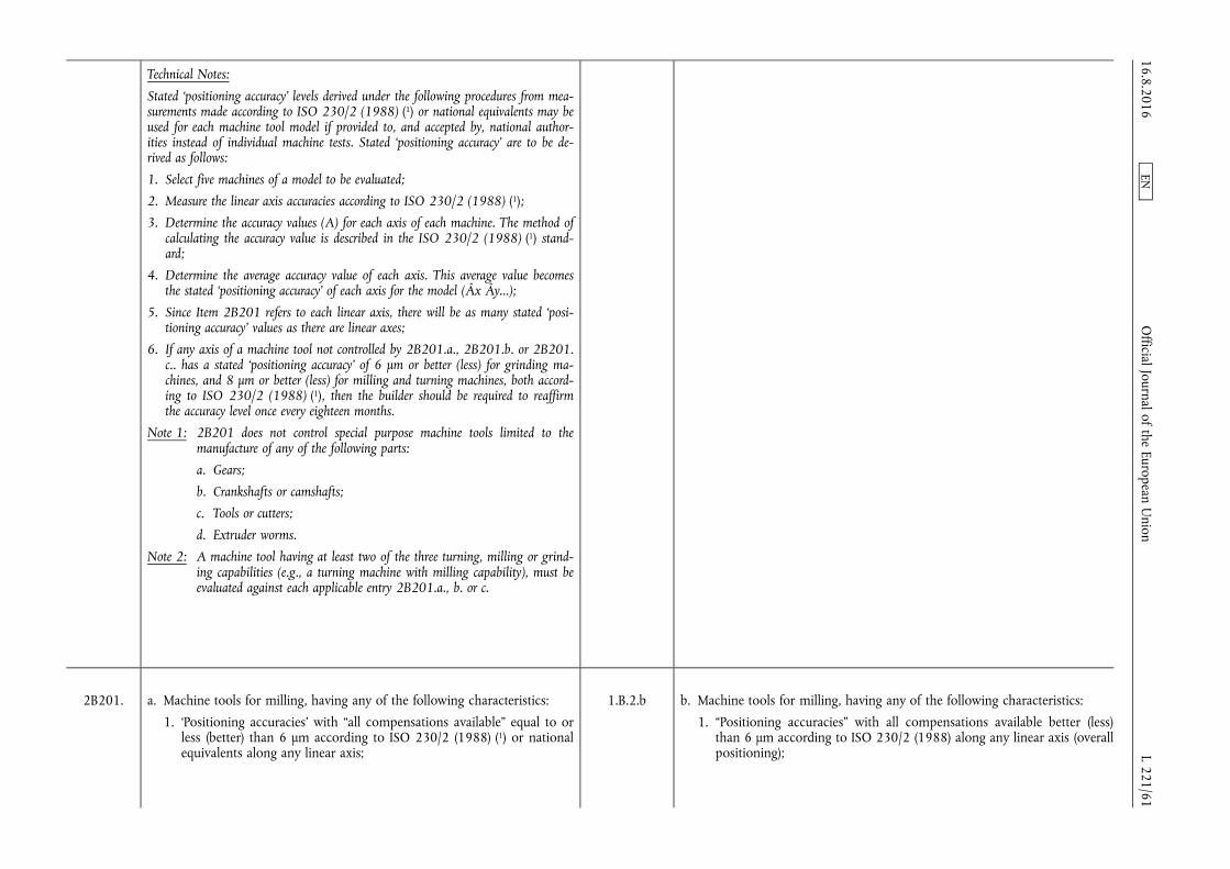
Technical Notes:
Stated ‘positioning accuracy’ levels derived under the following procedures from measurements made according to ISO 230/2 (1988) (1) or national equivalents may be used for each machine tool model if provided to, and accepted by, national authorities instead of individual machine tests. Stated ‘positioning accuracy’ are to be derived as follows:
1. Select five machines of a model to be evaluated;
2. Measure the linear axis accuracies according to ISO 230/2 (1988) (1);
3. Determine the accuracy values (A) for each axis of each machine. The method of calculating the accuracy value is described in the ISO 230/2 (1988) (1) standard;
4. Determine the average accuracy value of each axis. This average value becomes the stated ‘positioning accuracy’ of each axis for the model (Âx Ây...);
5. Since Item 2B201 refers to each linear axis, there will be as many stated ‘positioning accuracy’ values as there are linear axes;
6. If any axis of a machine tool not controlled by 2B201.a., 2B201.b. or 2B201. c.. has a stated ‘positioning accuracy’ of 6 µm or better (less) for grinding machines, and 8 µm or better (less) for milling and turning machines, both according to ISO 230/2 (1988) (1), then the builder should be required to reaffirm the accuracy level once every eighteen months.
Note 1: 2B201 does not control special purpose machine tools limited to the manufacture of any of the following parts:
a. Gears;
b. Crankshafts or camshafts;
c. Tools or cutters;
d. Extruder worms.
Note 2: A machine tool having at least two of the three turning, milling or grinding capabilities (e.g., a turning machine with milling capability), must be evaluated against each applicable entry 2B201.a., b. or c.
2B201. a. Machine tools for milling, having any of the following characteristics:
1. ‘Positioning accuracies’ with “all compensations available” equal to or less (better) than 6 µm according to ISO 230/2 (1988) (1) or national equivalents along any linear axis;
1.B.2.b b. Machine tools for milling, having any of the following characteristics:
1. “Positioning accuracies” with all compensations available better (less) than 6 μm according to ISO 230/2 (1988) along any linear axis (overall positioning);
16.8.2016 L 221/61
Official Journal of the European U
nion EN

2. Two or more contouring rotary axes; or
3. Five or more axes which can be coordinated simultaneously for “contouring control”;
Note: 2B201.a. does not control milling machines having the following characteristics:
a. X-axis travel greater than 2 m; and
b. Overall ‘positioning accuracy’ on the x-axis more (worse) than 30 µm.
2. Two or more contouring rotary axes; or
3. Five or more axes which can be coordinated simultaneously for “contouring control”.
Note: Item 1.B.2.b. does not control milling machines having both of the following characteristics:
1. X-axis travel greater than 2 m; and
2. Overall “positioning accuracy” on the x-axis worse (more) than 30 μm according to ISO 230/2 (1988)
2B201 b. Machine tools for grinding, having any of the following characteristics:
1. ‘Positioning accuracies’ with “all compensations available” equal to or less (better) than 4 µm according to ISO 230/2 (1988) (1) or national equivalents along any linear axis;
2. Two or more contouring rotary axes; or
3. Five or more axes which can be coordinated simultaneously for “contouring control”;
Note: 2B201.b. does not control grinding machines as follows:
a. Cylindrical external, internal, and external-internal grinding machines having all of the following characteristics:
1. Limited to a maximum workpiece capacity of 150 mm outside diameter or length; and
2. Axes limited to x, z and c;
b. Jig grinders that do not have a z-axis or a w-axis with an overall ‘positioning accuracy’ less (better) than 4 µm according to ISO 230/2 (1988) (1) or national equivalents.
c. Machine tools for turning, that have ‘positioning accuracies’ with “all compensations available” better (less) than 6 μm according to ISO 230/2 (1988) (1) along any linear axis (overall positioning) for machines capable of machining diameters greater than 35 mm;
Note: 2B201.c. does not control bar machines (Swissturn), limited to machining only bar feed thru, if maximum bar diameter is equal to or less than 42 mm and there is no capability of mounting chucks. Machines may have drilling and/or milling capabilities for machining parts with diameters less than 42 mm.
1.B.2.c c. Machine tools for grinding, having any of the following characteristics:
1. “Positioning accuracies” with all compensations available better (less) than 4 μm according to ISO 230/2 (1988) along any linear axis (overall positioning);
2. Two or more contouring rotary axes; or
3 Five or more axes which can be coordinated simultaneously for “contouring control”.
Note: Item 1.B.2.c. does not control grinding machines as follows:
1. Cylindrical external, internal, and external-internal grinding machines having all the following characteristics:
a. Limited to a maximum workpiece capacity of 150 mm outside diameter or length; and
b. Axes limited to x, z and c.
2. Jig grinders that do not have a z-axis or a w-axis with an overall positioning accuracy less (better) than 4 microns. Positioning accuracy is according to ISO 230/2 (1988).
16.8.2016 L 221/62
Official Journal of the European U
nion EN
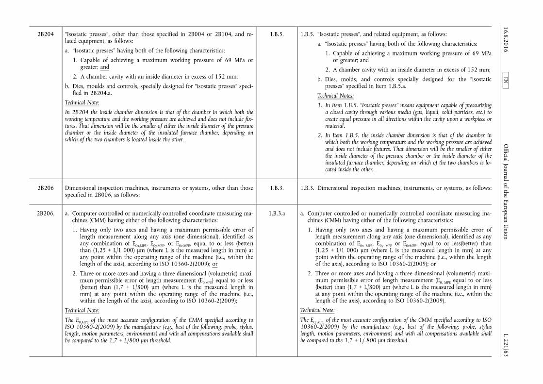
2B204 “Isostatic presses”, other than those specified in 2B004 or 2B104, and related equipment, as follows:
a. “Isostatic presses” having both of the following characteristics:
1. Capable of achieving a maximum working pressure of 69 MPa or greater; and
2. A chamber cavity with an inside diameter in excess of 152 mm;
b. Dies, moulds and controls, specially designed for “isostatic presses” specified in 2B204.a.
Technical Note:
In 2B204 the inside chamber dimension is that of the chamber in which both the working temperature and the working pressure are achieved and does not include fixtures. That dimension will be the smaller of either the inside diameter of the pressure chamber or the inside diameter of the insulated furnace chamber, depending on which of the two chambers is located inside the other.
1.B.5. 1.B.5. “Isostatic presses”, and related equipment, as follows:
a. “Isostatic presses” having both of the following characteristics:
1. Capable of achieving a maximum working pressure of 69 MPa or greater; and
2. A chamber cavity with an inside diameter in excess of 152 mm;
b. Dies, molds, and controls specially designed for the “isostatic presses” specified in Item 1.B.5.a.
Technical Notes:
1. In Item 1.B.5. “Isostatic presses” means equipment capable of pressurizing a closed cavity through various media (gas, liquid, solid particles, etc.) to create equal pressure in all directions within the cavity upon a workpiece or material.
2. In Item 1.B.5. the inside chamber dimension is that of the chamber in which both the working temperature and the working pressure are achieved and does not include fixtures. That dimension will be the smaller of either the inside diameter of the pressure chamber or the inside diameter of the insulated furnace chamber, depending on which of the two chambers is located inside the other.
2B206 Dimensional inspection machines, instruments or systems, other than those specified in 2B006, as follows:
1.B.3. 1.B.3. Dimensional inspection machines, instruments, or systems, as follows:
2B206. a. Computer controlled or numerically controlled coordinate measuring machines (CMM) having either of the following characteristics:
1. Having only two axes and having a maximum permissible error of length measurement along any axis (one dimensional), identified as any combination of E0x,MPE, E0y,MPE, or E0z,MPE, equal to or less (better) than (1,25 + L/1 000) µm (where L is the measured length in mm) at any point within the operating range of the machine (i.e., within the length of the axis), according to ISO 10360-2(2009); or
2. Three or more axes and having a three dimensional (volumetric) maximum permissible error of length measurement (E0,MPE) equal to or less (better) than (1,7 + L/800) µm (where L is the measured length in mm) at any point within the operating range of the machine (i.e., within the length of the axis), according to ISO 10360-2(2009);
Technical Note:
The E0,MPE of the most accurate configuration of the CMM specified according to ISO 10360-2(2009) by the manufacturer (e.g., best of the following: probe, stylus, length, motion parameters, environments) and with all compensations available shall be compared to the 1,7 + L/800 µm threshold.
1.B.3.a a. Computer controlled or numerically controlled coordinate measuring machines (CMM) having either of the following characteristics:
1. Having only two axes and having a maximum permissible error of length measurement along any axis (one dimensional), identified as any combination of E0x MPE, E0y MPE or E0zMPE, equal to or less(better) than (1,25 + L/1 000) μm (where L is the measured length in mm) at any point within the operating range of the machine (i.e., within the length of the axis), according to ISO 10360-2(2009); or
2. Three or more axes and having a three dimensional (volumetric) maximum permissible error of length measurement (E0, MPE equal to or less (better) than (1,7 + L/800) μm (where L is the measured length in mm) at any point within the operating range of the machine (i.e., within the length of the axis), according to ISO 10360-2(2009).
Technical Note:
The E0, MPE of the most accurate configuration of the CMM specified according to ISO 10360-2(2009) by the manufacturer (e.g., best of the following: probe, stylus length, motion parameters, environment) and with all compensations available shall be compared to the 1,7 + L/ 800 μm threshold.
16.8.2016 L 221/63
Official Journal of the European U
nion EN
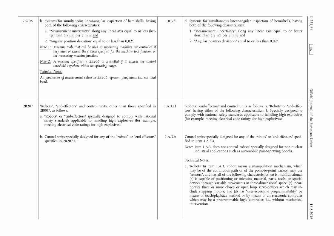
2B206. b. Systems for simultaneous linear-angular inspection of hemishells, having both of the following characteristics:
1. “Measurement uncertainty” along any linear axis equal to or less (better) than 3,5 µm per 5 mm; and
2. “Angular position deviation” equal to or less than 0,02°.
Note 1: Machine tools that can be used as measuring machines are controlled if they meet or exceed the criteria specified for the machine tool function or the measuring machine function.
Note 2: A machine specified in 2B206 is controlled if it exceeds the control threshold anywhere within its operating range.
Technical Notes:
All parameters of measurement values in 2B206 represent plus/minus i.e., not total band.
1.B.3.d d. Systems for simultaneous linear-angular inspection of hemishells, having both of the following characteristics:
1. “Measurement uncertainty” along any linear axis equal to or better (less) than 3,5 μm per 5 mm; and
2. “Angular position deviation” equal to or less than 0,02°.
2B207 “Robots”, “end-effectors” and control units, other than those specified in 2B007, as follows:
a. “Robots” or “end-effectors” specially designed to comply with national safety standards applicable to handling high explosives (for example, meeting electrical code ratings for high explosives);
1.A.3.a1 ‘Robots’, ‘end-effectors’ and control units as follows: a. ‘Robots’ or ‘end-effectors’ having either of the following characteristics: 1. Specially designed to comply with national safety standards applicable to handling high explosives (for example, meeting electrical code ratings for high explosives);
b. Control units specially designed for any of the “robots” or “end-effectors” specified in 2B207.a.
1.A.3.b Control units specially designed for any of the ‘robots’ or ‘end-effectors’ specified in Item 1.A.3.a.
Note: Item 1.A.3. does not control ‘robots’ specially designed for non-nuclear industrial applications such as automobile paint-spraying booths.
Technical Notes:
1. ‘Robots’ In Item 1.A.3. ‘robot’ means a manipulation mechanism, which may be of the continuous path or of the point-to-point variety, may use “sensors”, and has all of the following characteristics: (a) is multifunctional; (b) is capable of positioning or orienting material, parts, tools, or special devices through variable movements in three-dimensional space; (c) incorporates three or more closed or open loop servo-devices which may include stepping motors; and (d) has “user-accessible programmability” by means of teach/playback method or by means of an electronic computer which may be a programmable logic controller, i.e., without mechanical intervention. 16.8.2016
L 221/64 O
fficial Journal of the European Union
EN
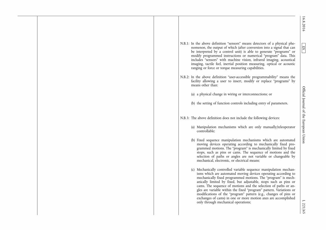
N.B.1: In the above definition “sensors” means detectors of a physical phenomenon, the output of which (after conversion into a signal that can be interpreted by a control unit) is able to generate “programs” or modify programmed instructions or numerical “program” data. This includes “sensors” with machine vision, infrared imaging, acoustical imaging, tactile feel, inertial position measuring, optical or acoustic ranging or force or torque measuring capabilities.
N.B.2: In the above definition “user-accessible programmability” means the facility allowing a user to insert, modify or replace “programs” by means other than:
(a) a physical change in wiring or interconnections; or
(b) the setting of function controls including entry of parameters.
N.B.3: The above definition does not include the following devices:
(a) Manipulation mechanisms which are only manually/teleoperator controllable;
(b) Fixed sequence manipulation mechanisms which are automated moving devices operating according to mechanically fixed programmed motions. The “program” is mechanically limited by fixed stops, such as pins or cams. The sequence of motions and the selection of paths or angles are not variable or changeable by mechanical, electronic, or electrical means;
(c) Mechanically controlled variable sequence manipulation mechanisms which are automated moving devices operating according to mechanically fixed programmed motions. The “program” is mechanically limited by fixed, but adjustable, stops such as pins or cams. The sequence of motions and the selection of paths or angles are variable within the fixed “program” pattern. Variations or modifications of the “program” pattern (e.g., changes of pins or exchanges of cams) in one or more motion axes are accomplished only through mechanical operations;
16.8.2016 L 221/65
Official Journal of the European U
nion EN
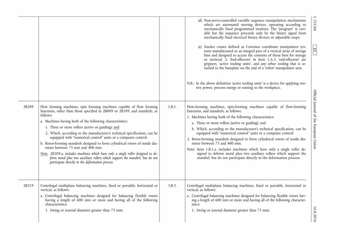
(d) Non-servo-controlled variable sequence manipulation mechanisms which are automated moving devices, operating according to mechanically fixed programmed motions. The “program” is variable but the sequence proceeds only by the binary signal from mechanically fixed electrical binary devices or adjustable stops;
(e) Stacker cranes defined as Cartesian coordinate manipulator systems manufactured as an integral part of a vertical array of storage bins and designed to access the contents of those bins for storage or retrieval. 2. ‘End-effectors’ In Item 1.A.3. ‘end-effectors’ are grippers, ‘active tooling units’, and any other tooling that is attached to the baseplate on the end of a ‘robot’ manipulator arm.
N.B.: In the above definition ‘active tooling units’ is a device for applying motive power, process energy or sensing to the workpiece.
2B209 Flow forming machines, spin forming machines capable of flow forming functions, other than those specified in 2B009 or 2B109, and mandrels, as follows:
a. Machines having both of the following characteristics:
1. Three or more rollers (active or guiding); and
2. Which, according to the manufacturer's technical specification, can be equipped with “numerical control” units or a computer control;
b. Rotor-forming mandrels designed to form cylindrical rotors of inside diameter between 75 mm and 400 mm.
Note: 2B209.a. includes machines which have only a single roller designed to deform metal plus two auxiliary rollers which support the mandrel, but do not participate directly in the deformation process.
1.B.1. Flow-forming machines, spin-forming machines capable of flow-forming functions, and mandrels, as follows:
1. Machines having both of the following characteristics:
a. Three or more rollers (active or guiding); and
b. Which, according to the manufacturer's technical specification, can be equipped with “numerical control” units or a computer control;
2. Rotor-forming mandrels designed to form cylindrical rotors of inside diameter between 75 and 400 mm.
Note: Item 1.B.1.a. includes machines which have only a single roller designed to deform metal plus two auxiliary rollers which support the mandrel, but do not participate directly in the deformation process.
2B219 Centrifugal multiplane balancing machines, fixed or portable, horizontal or vertical, as follows:
a. Centrifugal balancing machines designed for balancing flexible rotors having a length of 600 mm or more and having all of the following characteristics:
1. Swing or journal diameter greater than 75 mm;
3.B.3. Centrifugal multiplane balancing machines, fixed or portable, horizontal or vertical, as follows:
a. Centrifugal balancing machines designed for balancing flexible rotors having a length of 600 mm or more and having all of the following characteristics:
1. Swing or journal diameter greater than 75 mm;
16.8.2016 L 221/66
Official Journal of the European U
nion EN
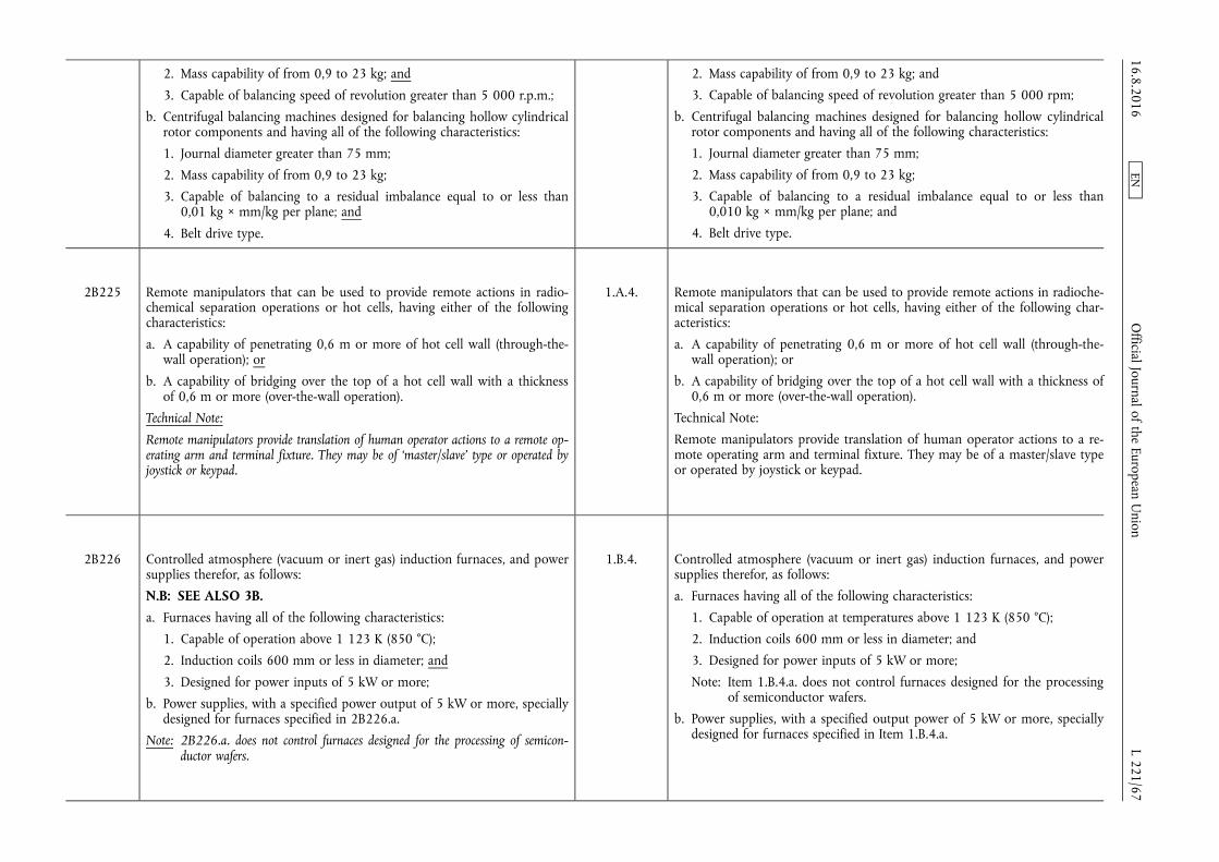
2. Mass capability of from 0,9 to 23 kg; and
3. Capable of balancing speed of revolution greater than 5 000 r.p.m.;
b. Centrifugal balancing machines designed for balancing hollow cylindrical rotor components and having all of the following characteristics:
1. Journal diameter greater than 75 mm;
2. Mass capability of from 0,9 to 23 kg;
3. Capable of balancing to a residual imbalance equal to or less than 0,01 kg × mm/kg per plane; and
4. Belt drive type.
2. Mass capability of from 0,9 to 23 kg; and
3. Capable of balancing speed of revolution greater than 5 000 rpm;
b. Centrifugal balancing machines designed for balancing hollow cylindrical rotor components and having all of the following characteristics:
1. Journal diameter greater than 75 mm;
2. Mass capability of from 0,9 to 23 kg;
3. Capable of balancing to a residual imbalance equal to or less than 0,010 kg × mm/kg per plane; and
4. Belt drive type.
2B225 Remote manipulators that can be used to provide remote actions in radiochemical separation operations or hot cells, having either of the following characteristics:
a. A capability of penetrating 0,6 m or more of hot cell wall (through-the- wall operation); or
b. A capability of bridging over the top of a hot cell wall with a thickness of 0,6 m or more (over-the-wall operation).
Technical Note:
Remote manipulators provide translation of human operator actions to a remote operating arm and terminal fixture. They may be of ‘master/slave’ type or operated by joystick or keypad.
1.A.4. Remote manipulators that can be used to provide remote actions in radiochemical separation operations or hot cells, having either of the following characteristics:
a. A capability of penetrating 0,6 m or more of hot cell wall (through-the- wall operation); or
b. A capability of bridging over the top of a hot cell wall with a thickness of 0,6 m or more (over-the-wall operation).
Technical Note:
Remote manipulators provide translation of human operator actions to a remote operating arm and terminal fixture. They may be of a master/slave type or operated by joystick or keypad.
2B226 Controlled atmosphere (vacuum or inert gas) induction furnaces, and power supplies therefor, as follows:
N.B: SEE ALSO 3B. a. Furnaces having all of the following characteristics:
1. Capable of operation above 1 123 K (850 °C);
2. Induction coils 600 mm or less in diameter; and
3. Designed for power inputs of 5 kW or more;
b. Power supplies, with a specified power output of 5 kW or more, specially designed for furnaces specified in 2B226.a.
Note: 2B226.a. does not control furnaces designed for the processing of semiconductor wafers.
1.B.4. Controlled atmosphere (vacuum or inert gas) induction furnaces, and power supplies therefor, as follows:
a. Furnaces having all of the following characteristics:
1. Capable of operation at temperatures above 1 123 K (850 °C);
2. Induction coils 600 mm or less in diameter; and
3. Designed for power inputs of 5 kW or more;
Note: Item 1.B.4.a. does not control furnaces designed for the processing of semiconductor wafers.
b. Power supplies, with a specified output power of 5 kW or more, specially designed for furnaces specified in Item 1.B.4.a.
16.8.2016 L 221/67
Official Journal of the European U
nion EN

2B227 Vacuum or other controlled atmosphere metallurgical melting and casting furnaces and related equipment as follows:
a. Arc remelt and casting furnaces having both of the following characteristics:
1. Consumable electrode capacities between 1 000 cm3 and 20 000 cm3; and
2. Capable of operating with melting temperatures above 1 973 K (1 700 °C);
b. Electron beam melting furnaces and plasma atomization and melting furnaces, having both of the following characteristics:
1. A power of 50 kW or greater; and
2. Capable of operating with melting temperatures above 1 473 K (1 200 °C).
c. Computer control and monitoring systems specially configured for any of the furnaces specified in 2B227.a. or b.
1.B.7. Vacuum or other controlled atmosphere metallurgical melting and casting furnaces and related equipment, as follows:
a. Arc remelt and casting furnaces having both of the following characteristics:
1. Consumable electrode capacities between 1 000 and 20 000 cm3; and
2. Capable of operating with melting temperatures above 1 973 K (1 700 °C);
b. Electron beam melting furnaces and plasma atomization and melting furnaces, having both of the following characteristics:
1. A power of 50 kW or greater; and
2. Capable of operating with melting temperatures above 1 473 K (1 200 °C);
c. Computer control and monitoring systems specially configured for any of the furnaces specified in Item 1.B.7.a. or 1.B.7.b.
2B228 Rotor fabrication or assembly equipment, rotor straightening equipment, bellows-forming mandrels and dies, as follows:
a. Rotor assembly equipment for assembly of gas centrifuge rotor tube sections, baffles, and end caps;
Note: 2B228.a. includes precision mandrels, clamps, and shrink fit machines.
b. Rotor straightening equipment for alignment of gas centrifuge rotor tube sections to a common axis;
Technical Note:
In 2B228.b. such equipment normally consists of precision measuring probes linked to a computer that subsequently controls the action of, for example, pneumatic rams used for aligning the rotor tube sections.
c. Bellows-forming mandrels and dies for producing single-convolution bellows.
Technical Note:
In 2B228.c. the bellows have all of the following characteristics:
1. Inside diameter between 75 mm and 400 mm;
2. Length equal to or greater than 12,7 mm;
3.B.2. Rotor fabrication or assembly equipment, rotor straightening equipment, bellows-forming mandrels and dies, as follows:
a. Rotor assembly equipment for assembly of gas centrifuge rotor tube sections, baffles, and end caps;
Note: Item 3.B.2.a. includes precision mandrels, clamps, and shrink fit machines.
b. Rotor straightening equipment for alignment of gas centrifuge rotor tube sections to a common axis;
Technical Note:
In Item 3.B.2.b. such equipment normally consists of precision measuring probes linked to a computer that subsequently controls the action of, for example, pneumatic rams used for aligning the rotor tube sections.
c. Bellows-forming mandrels and dies for producing single-convolution bellows.
Technical Note:
The bellows referred to in Item 3.B.2.c. have all of the following characteristics:
1. Inside diameter between 75 and 400 mm;
2. Length equal to or greater than 12,7 mm;
16.8.2016 L 221/68
Official Journal of the European U
nion EN

3. Single convolution depth greater than 2 mm; and
4. Made of high-strength aluminium alloys, maraging steel or high strength “fibrous or filamentary materials”.
3. Single convolution depth greater than 2 mm; and
4. Made of high-strength aluminium alloys, maraging steel, or high strength “fibrous or filamentary materials”.
2B230 All types of ‘pressure transducers’ capable of measuring absolute pressures and having all of the following:
a. Pressure sensing elements made of or protected by aluminium, aluminium alloy, aluminum oxide (alumina or sapphire), nickel, nickel alloy with more than 60 % nickel by weight, or fully fluorinated hydrocarbon polymers;
b. Seals, if any, essential for sealing the pressure sensing element, and in direct contact with the process medium, made of or protected by aluminium, aluminium alloy, aluminum oxide (alumina or sapphire), nickel, nickel alloy with more than 60 % nickel by weight, or fully fluorinated hydrocarbon polymers; and
c. Having either of the following characteristics:
1. A full scale of less than 13 kPa and an ‘accuracy’ of better than ± 1 % of full-scale; or
2. A full scale of 13 kPa or greater and an ‘accuracy’ of better than ± 130 Pa when measured at 13 kPa.
Technical Notes:
1. In 2B230 ‘pressure transducer’ means a device that converts a pressure measurement into a signal.
2. For the purposes of 2B230, ‘accuracy’ includes non-linearity, hysteresis and repeatability at ambient temperature.
3.A.7. All types of pressure transducers capable of measuring absolute pressures and having all of the following characteristics:
a. Pressure sensing elements made of or protected by aluminium, aluminium alloy, aluminium oxide (alumina or sapphire), nickel, nickel alloy with more than 60 % nickel by weight, or fully fluorinated hydrocarbon polymers;
b. Seals, if any, essential for sealing the pressure sensing element, and in direct contact with the process medium, made of or protected by aluminium, aluminium alloy, aluminium oxide (alumina or sapphire), nickel, nickel alloy with more than 60 % nickel by weight, or fully fluorinated hydrocarbon polymers; and
c. Having either of the following characteristics:
1. A full scale of less than 13 kPa and an “accuracy” of better than ± 1 % of full scale; or
2. A full scale of 13 kPa or greater and an “accuracy” of better than ± 130 Pa when measuring at 13 kPa. Technical
Notes:
1. In Item 3.A.7. pressure transducers are devices that convert pressure measurements into a signal.
2. In Item 3.A.7. “accuracy” includes non-linearity, hysteresis and repeatability at ambient temperature.
2B231 Vacuum pumps having all of the following characteristics:
a. Input throat size equal to or greater than 380 mm;
b. Pumping speed equal to or greater than 15 m3/s; and
c. Capable of producing an ultimate vacuum better than 13 mPa.
Technical Notes:
1. The pumping speed is determined at the measurement point with nitrogen gas or air.
2. The ultimate vacuum is determined at the input of the pump with the input of the pump blocked off.
3.A.8. Vacuum pumps having all of the following characteristics:
a. Input throat size equal to or greater than 380 mm;
b. Pumping speed equal to or greater than 15 m3/s; and
c. Capable of producing an ultimate vacuum better than 13,3 mPa.
Technical Notes:
1. The pumping speed is determined at the measurement point with nitrogen gas or air.
2. The ultimate vacuum is determined at the input of the pump with the input of the pump blocked off.
16.8.2016 L 221/69
Official Journal of the European U
nion EN

2B232 High-velocity gun systems (propellant, gas, coil, electromagnetic, and electrothermal types, and other advanced systems) capable of accelerating projectiles to 1,5 km/s or greater.
N.B.: SEE ALSO MILTARY GOODS CONTROLS.
5.B.2. High-velocity gun systems (propellant, gas, coil, electromagnetic, and electrothermal types, and other advanced systems) capable of accelerating projectiles to 1,5 km/s or greater.
Note: This item does not control guns specially designed for high velocity weapon systems.
2B233 Bellows-sealed scroll-type compressors and bellows-sealed scroll-type vacuum pumps having all of the following:
N.B.: SEE ALSO 2B350.i. a. Capable of an inlet volume flow rate of 50 m3/h or greater;
b. Capable of a pressure ratio of 2:1 or greater; and
c. Having all surfaces that come in contact with the process gas made from any of the following materials:
1. Aluminium or aluminium alloy;
2. Aluminium oxide;
3. Stainless steel;
4. Nickel or nickel alloy;
5. Phosphor bronze; or
6. Fluoropolymers.
3.A.9. Bellows-sealed scroll-type compressors and bellows-sealed scroll-type vacuum pumps having all of the following characteristics:
a. Capable of an inlet volume flow rate of 50 m3/h or greater;
b. Capable of a pressure ratio of 2:1 or greater; and
c. Having all surfaces that come in contact with the process gas made from any of the following materials:
1. Aluminium or aluminium alloy;
2. Aluminium oxide;
3. Stainless steel;
4. Nickel or nickel alloy;
5. Phosphor bronze; or
6. Fluoropolymers.
Technical Notes:
1. In a scroll compressor or vacuum pump, crescent-shaped pockets of gas are trapped between one or more pairs of intermeshed spiral vanes, or scrolls, one of which moves while the other remains stationary. The moving scroll orbits the stationary scroll; it does not rotate. As the moving scroll orbits the stationary scroll, the gas pockets diminish in size (i.e., they are compressed) as they move toward the outlet port of the machine.
2. In a bellows-sealed scroll compressor or vacuum pump, the process gas is totally isolated from the lubricated parts of the pump and from the external atmosphere by a metal bellows. One end of the bellows is attached to the moving scroll and the other end is attached to the stationary housing of the pump. 16.8.2016
L 221/70 O
fficial Journal of the European Union
EN
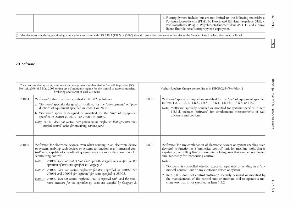
3. Fluoropolymers include, but are not limited to, the following materials: a. Polytetrafluoroethylene (PTFE), b. Fluorinated Ethylene Propylene (FEP), c. Perfluoroalkoxy (PFA), d. Polychlorotrifluoroethylene (PCTFE); and e. Vinylidene fluoride-hexafluoropropylene copolymer.
(1) Manufacturers calculating positioning accuracy in accordance with ISO 230/2 (1997) or (2006) should consult the competent authorities of the Member State in which they are established.
2D Software
The corresponding systems, equipment and components as identified in Council Regulation (EC) No 428/2009 of 5 May 2009 setting up a Community regime for the control of exports, transfer,
brokering and transit of dual-use items Nuclear Suppliers Group's control list as in INFCIRC/254/Rev.9/Part 2
2D001 “Software”, other than that specified in 2D002, as follows:
a. “Software” specially designed or modified for the “development” or “production” of equipment specified in 2A001 or 2B001
b. “Software” specially designed or modified for the “use” of equipment specified in 2A001.c., 2B001 or 2B003 to 2B009.
Note: 2D001 does not control part programming “software” that generates “numerical control” codes for machining various parts.
1.D.2. “Software” specially designed or modified for the “use” of equipment specified in Item 1.A.3., 1.B.1., 1.B.3., 1.B.5., 1.B.6.a., 1.B.6.b., 1.B.6.d. or 1.B.7.
Note: “Software” specially designed or modified for systems specified in Item 1.B.3.d. includes “software” for simultaneous measurements of wall thickness and contour.
2D002 “Software” for electronic devices, even when residing in an electronic device or system, enabling such devices or systems to function as a “numerical control” unit, capable of co-ordinating simultaneously more than four axes for “contouring control”.
Note 1: 2D002 does not control “software” specially designed or modified for the operation of items not specified in Category 2.
Note 2: 2D002 does not control “software” for items specified in 2B002. See 2D001 and 2D003 for “software” for items specified in 2B002.
Note 3: 2D002 does not control “software” that is exported with, and the minimum necessary for the operation of, items not specified by Category 2.
1.D.3. “Software” for any combination of electronic devices or system enabling such device(s) to function as a “numerical control” unit for machine tools, that is capable of controlling five or more interpolating axes that can be coordinated simultaneously for “contouring control”.
Notes:
1. “Software” is controlled whether exported separately or residing in a “numerical control” unit or any electronic device or system.
2. Item 1.D.3. does not control “software” specially designed or modified by the manufacturers of the control unit or machine tool to operate a machine tool that is not specified in Item 1.B.2.
16.8.2016 L 221/71
Official Journal of the European U
nion EN
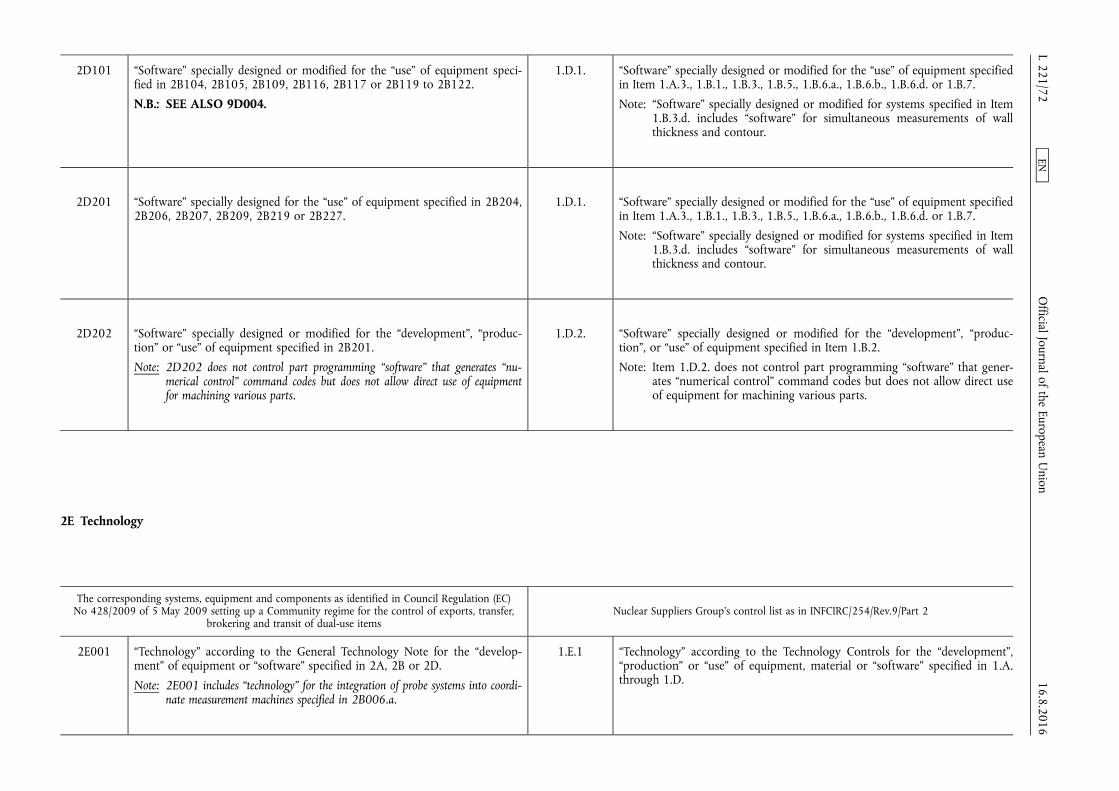
2D101 “Software” specially designed or modified for the “use” of equipment specified in 2B104, 2B105, 2B109, 2B116, 2B117 or 2B119 to 2B122.
N.B.: SEE ALSO 9D004.
1.D.1. “Software” specially designed or modified for the “use” of equipment specified in Item 1.A.3., 1.B.1., 1.B.3., 1.B.5., 1.B.6.a., 1.B.6.b., 1.B.6.d. or 1.B.7.
Note: “Software” specially designed or modified for systems specified in Item 1.B.3.d. includes “software” for simultaneous measurements of wall thickness and contour.
2D201 “Software” specially designed for the “use” of equipment specified in 2B204, 2B206, 2B207, 2B209, 2B219 or 2B227.
1.D.1. “Software” specially designed or modified for the “use” of equipment specified in Item 1.A.3., 1.B.1., 1.B.3., 1.B.5., 1.B.6.a., 1.B.6.b., 1.B.6.d. or 1.B.7.
Note: “Software” specially designed or modified for systems specified in Item 1.B.3.d. includes “software” for simultaneous measurements of wall thickness and contour.
2D202 “Software” specially designed or modified for the “development”, “production” or “use” of equipment specified in 2B201.
Note: 2D202 does not control part programming “software” that generates “numerical control” command codes but does not allow direct use of equipment for machining various parts.
1.D.2. “Software” specially designed or modified for the “development”, “production”, or “use” of equipment specified in Item 1.B.2.
Note: Item 1.D.2. does not control part programming “software” that generates “numerical control” command codes but does not allow direct use of equipment for machining various parts.
2E Technology
The corresponding systems, equipment and components as identified in Council Regulation (EC) No 428/2009 of 5 May 2009 setting up a Community regime for the control of exports, transfer,
brokering and transit of dual-use items Nuclear Suppliers Group's control list as in INFCIRC/254/Rev.9/Part 2
2E001 “Technology” according to the General Technology Note for the “development” of equipment or “software” specified in 2A, 2B or 2D.
Note: 2E001 includes “technology” for the integration of probe systems into coordinate measurement machines specified in 2B006.a.
1.E.1 “Technology” according to the Technology Controls for the “development”, “production” or “use” of equipment, material or “software” specified in 1.A. through 1.D. 16.8.2016
L 221/72 O
fficial Journal of the European Union
EN

2E002 “Technology” according to the General Technology Note for the “production” of equipment specified in 2A or 2B
1.E.1 “Technology” according to the Technology Controls for the “development”, “production” or “use” of equipment, material or “software” specified in 1.A. through 1.D.
2E101 “Technology” according to the General Technology Note for the “use” of equipment or “software” specified in 2B004, 2B009, 2B104, 2B109, 2B116, 2B119 to 2B122 or 2D101.
1.E.1 “Technology” according to the Technology Controls for the “development”, “production” or “use” of equipment, material or “software” specified in 1.A. through 1.D.
2E201 “Technology” according to the General Technology Note for the “use” of equipment or “software” specified in 2A225, 2A226, 2B001, 2B006, 2B007.b., 2B007.c., 2B008, 2B009, 2B201, 2B204, 2B206, 2B207, 2B209, 2B225 to 2B233, 2D201 or 2D202.
1.E.1 “Technology” according to the Technology Controls for the “development”, “production” or “use” of equipment, material or “software” specified in 1.A. through 1.D.
CATEGORY 3 — ELECTRONICS
3A Systems, Equipment and Components
The corresponding systems, equipment and components as identified in Council Regulation (EC) No 428/2009 of 5 May 2009 setting up a Community regime for the control of exports, transfer,
brokering and transit of dual-use items Nuclear Suppliers Group's control list as in INFCIRC/254/Rev.9/Part 2
3A201 Electronic components, other than those specified in 3A001, as follows;
a. Capacitors having either of the following sets of characteristics:
1. a. Voltage rating greater than 1,4 kV;
b. Energy storage greater than 10 J;
c. Capacitance greater than 0,5 µF; and
d. Series inductance less than 50 nH; or
2. a. Voltage rating greater than 750 V;
b. Capacitance greater than 0,25 µF; and
c. Series inductance less than 10 nH;
6.A.4. Pulse discharge capacitors having either of the following sets of characteristics:
a. 1. Voltage rating greater than 1,4 kV;
2. Energy storage greater than 10 J;
3. Capacitance greater than 0,5 μF; and
4. Series inductance less than 50 nH; or
b. 1. Voltage rating greater than 750 V;
2. Capacitance greater than 0,25 μF; and
3. Series inductance less than 10 nH.
16.8.2016 L 221/73
Official Journal of the European U
nion EN
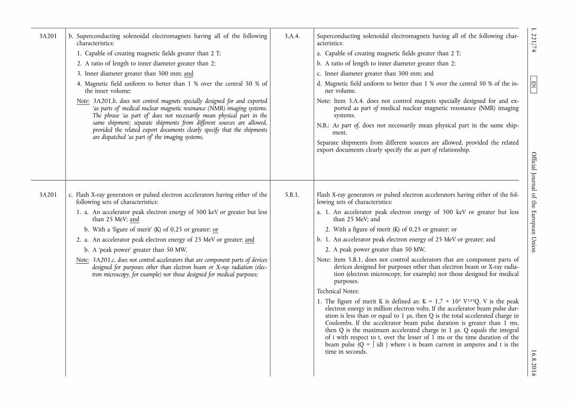
3A201 b. Superconducting solenoidal electromagnets having all of the following characteristics:
1. Capable of creating magnetic fields greater than 2 T;
2. A ratio of length to inner diameter greater than 2;
3. Inner diameter greater than 300 mm; and
4. Magnetic field uniform to better than 1 % over the central 50 % of the inner volume;
Note: 3A201.b. does not control magnets specially designed for and exported ‘as parts of’ medical nuclear magnetic resonance (NMR) imaging systems. The phrase ‘as part of’ does not necessarily mean physical part in the same shipment; separate shipments from different sources are allowed, provided the related export documents clearly specify that the shipments are dispatched ‘as part of’ the imaging systems.
3.A.4. Superconducting solenoidal electromagnets having all of the following characteristics:
a. Capable of creating magnetic fields greater than 2 T;
b. A ratio of length to inner diameter greater than 2;
c. Inner diameter greater than 300 mm; and
d. Magnetic field uniform to better than 1 % over the central 50 % of the inner volume.
Note: Item 3.A.4. does not control magnets specially designed for and exported as part of medical nuclear magnetic resonance (NMR) imaging systems.
N.B.: As part of, does not necessarily mean physical part in the same shipment.
Separate shipments from different sources are allowed, provided the related export documents clearly specify the as part of relationship.
3A201 c. Flash X-ray generators or pulsed electron accelerators having either of the following sets of characteristics:
1. a. An accelerator peak electron energy of 500 keV or greater but less than 25 MeV; and
b. With a ‘figure of merit’ (K) of 0,25 or greater; or
2. a. An accelerator peak electron energy of 25 MeV or greater; and
b. A ‘peak power’ greater than 50 MW.
Note: 3A201.c. does not control accelerators that are component parts of devices designed for purposes other than electron beam or X-ray radiation (electron microscopy, for example) nor those designed for medical purposes:
5.B.1. Flash X-ray generators or pulsed electron accelerators having either of the following sets of characteristics:
a. 1. An accelerator peak electron energy of 500 keV or greater but less than 25 MeV; and
2. With a figure of merit (K) of 0,25 or greater; or
b. 1. An accelerator peak electron energy of 25 MeV or greater; and
2. A peak power greater than 50 MW.
Note: Item 5.B.1. does not control accelerators that are component parts of devices designed for purposes other than electron beam or X-ray radiation (electron microscopy, for example) nor those designed for medical purposes.
Technical Notes:
1. The figure of merit K is defined as: K = 1,7 × 10³ V2,65Q. V is the peak electron energy in million electron volts. If the accelerator beam pulse duration is less than or equal to 1 µs, then Q is the total accelerated charge in Coulombs. If the accelerator beam pulse duration is greater than 1 ms, then Q is the maximum accelerated charge in 1 µs. Q equals the integral of i with respect to t, over the lesser of 1 ms or the time duration of the beam pulse (Q = ∫ idt ) where i is beam current in amperes and t is the time in seconds.
16.8.2016 L 221/74
Official Journal of the European U
nion EN
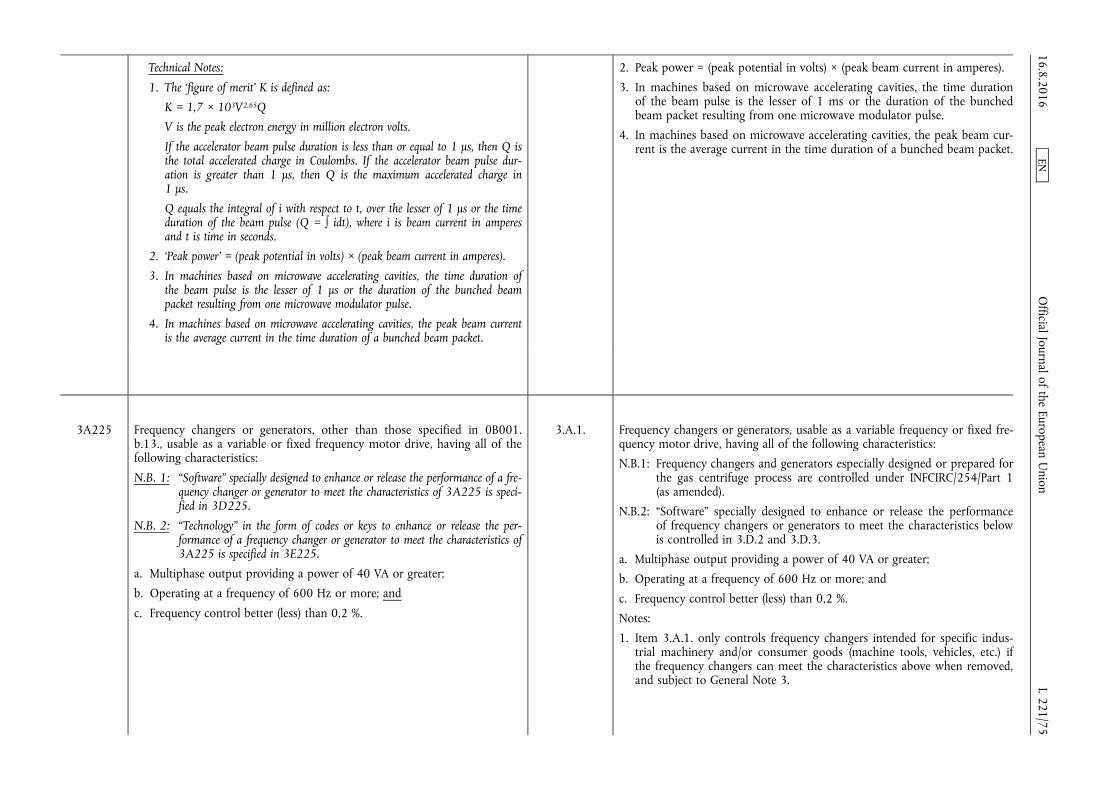
Technical Notes:
1. The ‘figure of merit’ K is defined as:
K = 1,7 × 10³V2,65Q
V is the peak electron energy in million electron volts.
If the accelerator beam pulse duration is less than or equal to 1 µs, then Q is the total accelerated charge in Coulombs. If the accelerator beam pulse duration is greater than 1 µs, then Q is the maximum accelerated charge in 1 µs.
Q equals the integral of i with respect to t, over the lesser of 1 µs or the time duration of the beam pulse (Q = ∫ idt), where i is beam current in amperes and t is time in seconds.
2. ‘Peak power’ = (peak potential in volts) × (peak beam current in amperes).
3. In machines based on microwave accelerating cavities, the time duration of the beam pulse is the lesser of 1 µs or the duration of the bunched beam packet resulting from one microwave modulator pulse.
4. In machines based on microwave accelerating cavities, the peak beam current is the average current in the time duration of a bunched beam packet.
2. Peak power = (peak potential in volts) × (peak beam current in amperes).
3. In machines based on microwave accelerating cavities, the time duration of the beam pulse is the lesser of 1 ms or the duration of the bunched beam packet resulting from one microwave modulator pulse.
4. In machines based on microwave accelerating cavities, the peak beam current is the average current in the time duration of a bunched beam packet.
3A225 Frequency changers or generators, other than those specified in 0B001. b.13., usable as a variable or fixed frequency motor drive, having all of the following characteristics:
N.B. 1: “Software” specially designed to enhance or release the performance of a frequency changer or generator to meet the characteristics of 3A225 is specified in 3D225.
N.B. 2: “Technology” in the form of codes or keys to enhance or release the performance of a frequency changer or generator to meet the characteristics of 3A225 is specified in 3E225.
a. Multiphase output providing a power of 40 VA or greater;
b. Operating at a frequency of 600 Hz or more; and
c. Frequency control better (less) than 0,2 %.
3.A.1. Frequency changers or generators, usable as a variable frequency or fixed frequency motor drive, having all of the following characteristics:
N.B.1: Frequency changers and generators especially designed or prepared for the gas centrifuge process are controlled under INFCIRC/254/Part 1 (as amended).
N.B.2: “Software” specially designed to enhance or release the performance of frequency changers or generators to meet the characteristics below is controlled in 3.D.2 and 3.D.3.
a. Multiphase output providing a power of 40 VA or greater;
b. Operating at a frequency of 600 Hz or more; and
c. Frequency control better (less) than 0,2 %.
Notes:
1. Item 3.A.1. only controls frequency changers intended for specific industrial machinery and/or consumer goods (machine tools, vehicles, etc.) if the frequency changers can meet the characteristics above when removed, and subject to General Note 3.
16.8.2016 L 221/75
Official Journal of the European U
nion EN

Note: 3A225 does not control frequency changers or generators if they have hardware, “software” or “technology” constraints that limit the performance to less than that specified above, provided they meet any of the following:
1. They need to be returned to the original manufacturer to make the enhancements or release the constraints;
2. They require “software” as specified in 3D225 to enhance or release the performance to meet the characteristics of 3A225; or
3. They require “technology” in the form of keys or codes as specified in 3E225 to enhance or release the performance to meet the characteristics of 3A225.
Technical Notes:
1. Frequency changers in 3A225 are also known as converters or inverters.
2. Frequency changers in 3A225 may be marketed as Generators, Electronic Test Equipment, AC Power Supplies, Variable Speed Motors Drives, Variable Speed Drives (VSDs), Variable Frequency Drives (VFDs), Adjustable Frequency Drives (AFDs), or Adjustable Speed Drives (ASDs).
2. For the purpose of export control, the Government will determine whether or not a particular frequency changer meets the characteristics above, taking into account hardware and software constraints.
Technical Notes:
1. Frequency changers in Item 3.A.1. are also known as converters or inverters.
2. The characteristics specified in item 3.A.1. may be met by certain equipment marketed such as: Generators, Electronic Test Equipment, AC Power Supplies, Variable Speed Motor Drives, Variable Speed Drives (VSDs), Variable Frequency Drives (VFDs), Adjustable Frequency Drives (AFDs), or Adjustable Speed Drives (ASDs).
3A226 High-power direct current power supplies, other than those specified in 0B001.j.6., having both of the following characteristics:
a. Capable of continuously producing, over a time period of 8 hours, 100 V or greater with current output of 500 A or greater; and
b. Current or voltage stability better than 0,1 % over a time period of 8 hours.
3.A.5. High-power direct current power supplies having both of the following characteristics:
a. Capable of continuously producing, over a time period of 8 hours, 100 V or greater with current output of 500 A or greater; and
b. Current or voltage stability better than 0,1 % over a time period of 8 hours.
3A227 High-voltage direct current power supplies, other than those specified in 0B001.j.5., having both of the following characteristics:
a. Capable of continuously producing, over a time period of 8 hours, 20 kV or greater with current output of 1 A or greater; and
b. Current or voltage stability better than 0,1 % over a time period of 8 hours.
3.A.6. High-voltage direct current power supplies having both of the following characteristics:
a. Capable of continuously producing, over a time period of 8 hours, 20 kV or greater with current output of 1 A or greater; and
b. Current or voltage stability better than 0,1 % over a time period of 8 hours. 16.8.2016
L 221/76 O
fficial Journal of the European Union
EN

3A228 Switching devices, as follows:
a. Cold-cathode tubes, whether gas filled or not, operating similarly to a spark gap, having all of the following characteristics:
1. Containing three or more electrodes;
2. Anode peak voltage rating of 2,5 kV or more;
3. Anode peak current rating of 100 A or more; and
4. Anode delay time of 10 µs or less;
Note: 3A228 includes gas krytron tubes and vacuum sprytron tubes.
b. Triggered spark-gaps having both of the following characteristics:
1. An anode delay time of 15 µs or less; and
2. Rated for a peak current of 500 A or more;
c. Modules or assemblies with a fast switching function, other than those specified in 3A001.g. or 3A001.h., having all of the following characteristics:
1. Anode peak voltage rating greater than 2 kV;
2. Anode peak current rating of 500 A or more; and
3. Turn-on time of 1 µs or less.
6.A.3. Switching devices as follows:
a. Cold-cathode tubes, whether gas filled or not, operating similarly to a spark gap, having all of the following characteristics:
1. Containing three or more electrodes;
2. Anode peak voltage rating of 2,5 kV or more;
3. Anode peak current rating of 100 A or more; and
4. Anode delay time of 10 µs or less;
Note: Item 6.A.3.a. includes gas krytron tubes and vacuum sprytron tubes.
b. Triggered spark-gaps having both of the following characteristics:
1. Anode delay time of 15 µs or less; and
2. Rated for a peak current of 500 A or more;
c. Modules or assemblies with a fast switching function having all of the following characteristics:
1. Anode peak voltage rating greater than 2 kV;
2. Anode peak current rating of 500 A or more; and
3. Turn-on time of 1 µs or less.
3A229 High-current pulse generators as follows:
N.B.: SEE ALSO MILITARY GOODS CONTROLS. a. Detonator firing sets (initiator systems, firesets), including electronically-
charged, explosively-driven and optically-driven firing sets, other than those specified in 1A007.a., designed to drive multiple controlled detonators specified in 1A007.b.;
b. Modular electrical pulse generators (pulsers) having all of the following characteristics:
1. Designed for portable, mobile, or ruggedized-use;
2. Capable of delivering their energy in less than 15 µs into loads of less than 40 ohms;
6.A.2. Firing sets and equivalent high-current pulse generators, as follows:
a. Detonator firing sets (initiation systems, firesets), including electronically- charged, explosively-driven and optically-driven firing sets designed to drive multiple controlled detonators specified by Item 6.A.1. above;
b. Modular electrical pulse generators (pulsers) having all of the following characteristics:
1. Designed for portable, mobile, or ruggedized-use;
2. Capable of delivering their energy in less than 15 µs into loads of less than 40 ohms;
16.8.2016 L 221/77
Official Journal of the European U
nion EN
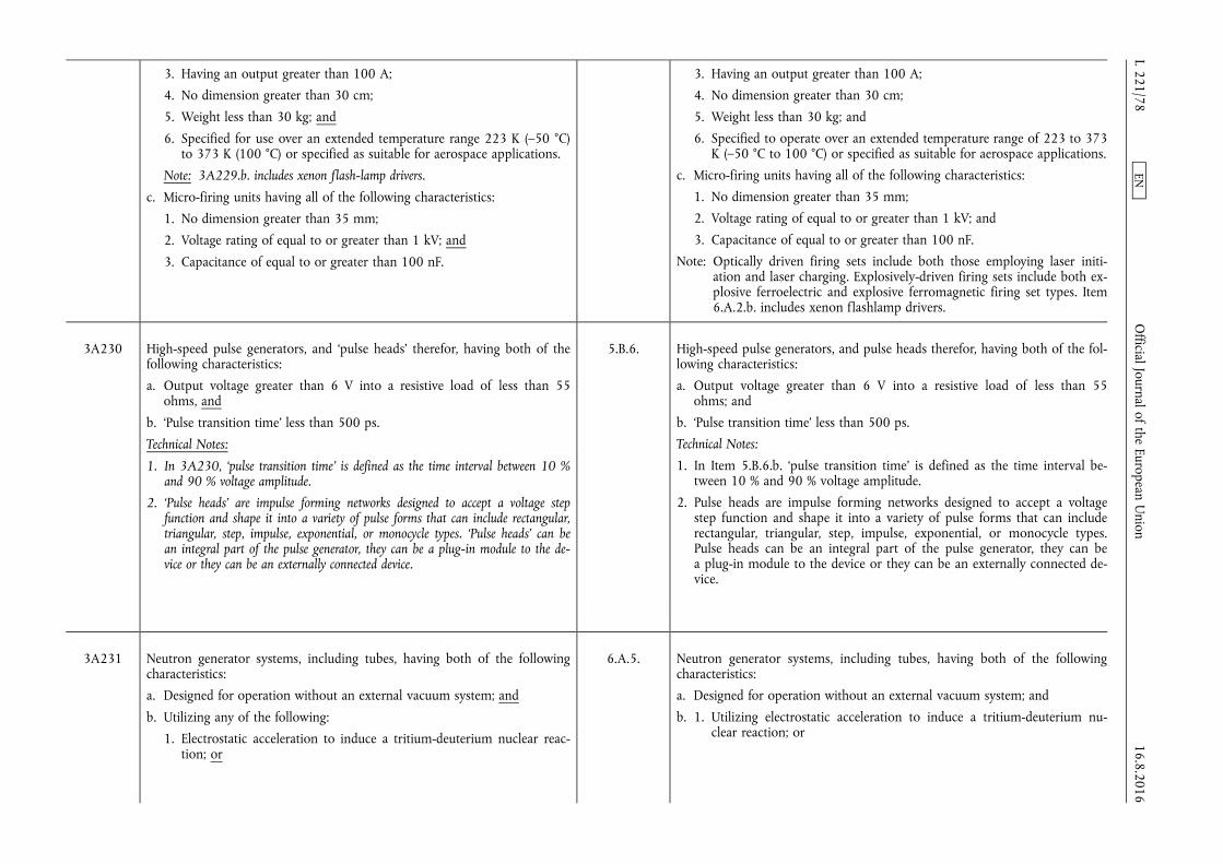
3. Having an output greater than 100 A;
4. No dimension greater than 30 cm;
5. Weight less than 30 kg; and
6. Specified for use over an extended temperature range 223 K (–50 °C) to 373 K (100 °C) or specified as suitable for aerospace applications.
Note: 3A229.b. includes xenon flash-lamp drivers.
c. Micro-firing units having all of the following characteristics:
1. No dimension greater than 35 mm;
2. Voltage rating of equal to or greater than 1 kV; and
3. Capacitance of equal to or greater than 100 nF.
3. Having an output greater than 100 A;
4. No dimension greater than 30 cm;
5. Weight less than 30 kg; and
6. Specified to operate over an extended temperature range of 223 to 373 K (–50 °C to 100 °C) or specified as suitable for aerospace applications.
c. Micro-firing units having all of the following characteristics:
1. No dimension greater than 35 mm;
2. Voltage rating of equal to or greater than 1 kV; and
3. Capacitance of equal to or greater than 100 nF.
Note: Optically driven firing sets include both those employing laser initiation and laser charging. Explosively-driven firing sets include both explosive ferroelectric and explosive ferromagnetic firing set types. Item 6.A.2.b. includes xenon flashlamp drivers.
3A230 High-speed pulse generators, and ‘pulse heads’ therefor, having both of the following characteristics:
a. Output voltage greater than 6 V into a resistive load of less than 55 ohms, and
b. ‘Pulse transition time’ less than 500 ps.
Technical Notes:
1. In 3A230, ‘pulse transition time’ is defined as the time interval between 10 % and 90 % voltage amplitude.
2. ‘Pulse heads’ are impulse forming networks designed to accept a voltage step function and shape it into a variety of pulse forms that can include rectangular, triangular, step, impulse, exponential, or monocycle types. ‘Pulse heads’ can be an integral part of the pulse generator, they can be a plug-in module to the device or they can be an externally connected device.
5.B.6. High-speed pulse generators, and pulse heads therefor, having both of the following characteristics:
a. Output voltage greater than 6 V into a resistive load of less than 55 ohms; and
b. ‘Pulse transition time’ less than 500 ps.
Technical Notes:
1. In Item 5.B.6.b. ‘pulse transition time’ is defined as the time interval between 10 % and 90 % voltage amplitude.
2. Pulse heads are impulse forming networks designed to accept a voltage step function and shape it into a variety of pulse forms that can include rectangular, triangular, step, impulse, exponential, or monocycle types. Pulse heads can be an integral part of the pulse generator, they can be a plug-in module to the device or they can be an externally connected device.
3A231 Neutron generator systems, including tubes, having both of the following characteristics:
a. Designed for operation without an external vacuum system; and
b. Utilizing any of the following:
1. Electrostatic acceleration to induce a tritium-deuterium nuclear reaction; or
6.A.5. Neutron generator systems, including tubes, having both of the following characteristics:
a. Designed for operation without an external vacuum system; and
b. 1. Utilizing electrostatic acceleration to induce a tritium-deuterium nuclear reaction; or 16.8.2016
L 221/78 O
fficial Journal of the European Union
EN

2. Electrostatic acceleration to induce a deuterium-deuterium nuclear reaction and capable of an output of 3 × 10⁹ neutrons/s or greater.
2. Utilizing electrostatic acceleration to induce a deuterium-deuterium nuclear reaction and capable of an output of 3 × 10⁹ neutrons/s or greater.
3A232 Multipoint initiation systems, other than those specified in 1A007, as follows:
N.B.: SEE ALSO MILITARY GOODS CONTROLS. N.B.: See 1A007.b. for detonators.
a. Not used;
b. Arrangements using single or multiple detonators designed to nearly simultaneously initiate an explosive surface over greater than 5 000 mm2
from a single firing signal with an initiation timing spread over the surface of less than 2,5 µs.
Note: 3A232 does not control detonators using only primary explosives, such as lead azide.
6.A.1. Detonators and multipoint initiation systems, as follows:
a. Electrically driven explosive detonators, as follows:
1. Exploding bridge (EB);
2. Exploding bridge wire (EBW);
3. Slapper;
4. Exploding foil initiators (EFI);
(see 3A232)
b. Arrangements using single or multiple detonators designed to nearly simultaneously initiate an explosive surface over an area greater than 5 000 mm2 from a single firing signal with an initiation timing spread over the surface of less than 2,5 µs.
Note: Item 6.A.1. does not control detonators using only primary explosives, such as lead azide.
Technical Note:
In Item 6.A.1. the detonators of concern all utilize a small electrical conductor (bridge, bridge wire, or foil) that explosively vaporizes when a fast, high- current electrical pulse is passed through it. In nonslapper types, the exploding conductor starts a chemical detonation in a contacting highexplosive material such as PETN (pentaerythritoltetranitrate). In slapper detonators, the explosive vaporization of the electrical conductor drives a flyer or slapper across a gap, and the impact of the slapper on an explosive starts a chemical detonation. The slapper in some designs is driven by magnetic force. The term exploding foil detonator may refer to either an EB or a slapper-type detonator. Also, the word initiator is sometimes used in place of the word detonator.
16.8.2016 L 221/79
Official Journal of the European U
nion EN

3A233 Mass spectrometers, other than those specified in 0B002.g., capable of measuring ions of 230 atomic mass units or greater and having a resolution of better than 2 parts in 230, as follows, and ion sources therefor:
a. Inductively coupled plasma mass spectrometers (ICP/MS);
b. Glow discharge mass spectrometers (GDMS);
c. Thermal ionization mass spectrometers (TIMS);
d. Electron bombardment mass spectrometers having both of the following features:
1. A molecular beam inlet system that injects a collimated beam of analyte molecules into a region of the ion source where the molecules are ionized by an electron beam; and
2. One or more ‘cold traps’ that can be cooled to a temperature of 193 K (–80 °C);
e. Not used;
f. Mass spectrometers equipped with a microfluorination ion source designed for actinides or actinide fluorides.
Technical Notes:
1. Electron bombardment mass spectrometers in 3A233.d. are also known as electron impact mass spectrometers or electron ionization mass spectrometers.
2. In 3A233.d.2., a ‘cold trap’ is a device that traps gas molecules by condensing or freezing them on cold surfaces. For the purposes of 3A233.d.2., a closed- loop gaseous helium cryogenic vacuum pump is not a ‘cold trap’.
3.B.6. Mass spectrometers capable of measuring ions of 230 atomic mass units or greater and having a resolution of better than 2 parts in 230, as follows, and ion sources therefor:
N.B.: Mass spectrometers especially designed or prepared for analyzing on- line samples of uranium hexafluoride are controlled under INFCIRC/ 254/Part 1 (as amended).
a. Inductively coupled plasma mass spectrometers (ICP/MS);
b. Glow discharge mass spectrometers (GDMS);
c. Thermal ionization mass spectrometers (TIMS);
d. Electron bombardment mass spectrometers having both of the following features:
1. A molecular beam inlet system that injects a collimated beam of analyte molecules into a region of the ion source where the molecules are ionized by an electron beam; and
2. One or more cold traps that can be cooled to a temperature of 193 K (–80 °C) or less in order to trap analyte molecules that are not ionized by the electron beam;
e. Mass spectrometers equipped with a microfluorination ion source designed for actinides or actinide fluorides.
3A234 Striplines to provide low inductance path to detonators with the following characteristics:
a. Voltage rating greater than 2 kV; and
b Inductance of less than 20 nH.
6.A.6. Striplines to provide low inductance path to detonators with the following characteristics:
a. Voltage rating greater than 2 kV; and
b. Inductance of less than 20 nH.
16.8.2016 L 221/80
Official Journal of the European U
nion EN
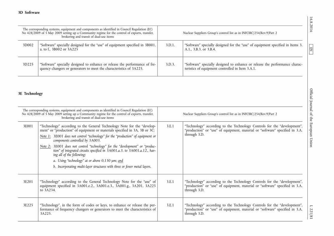
3D Software
The corresponding systems, equipment and components as identified in Council Regulation (EC) No 428/2009 of 5 May 2009 setting up a Community regime for the control of exports, transfer,
brokering and transit of dual-use items Nuclear Suppliers Group's control list as in INFCIRC/254/Rev.9/Part 2
3D002 “Software” specially designed for the “use” of equipment specified in 3B001. a. to f., 3B002 or 3A225
3.D.1. “Software” specially designed for the “use” of equipment specified in Items 3. A.1., 3.B.3. or 3.B.4.
3D225 “Software” specially designed to enhance or release the performance of frequency changers or generators to meet the characteristics of 3A225.
3.D.3. “Software” specially designed to enhance or release the performance characteristics of equipment controlled in Item 3.A.1.
3E Technology
The corresponding systems, equipment and components as identified in Council Regulation (EC) No 428/2009 of 5 May 2009 setting up a Community regime for the control of exports, transfer,
brokering and transit of dual-use items Nuclear Suppliers Group's control list as in INFCIRC/254/Rev.9/Part 2
3E001 “Technology” according to the General Technology Note for the “development” or “production” of equipment or materials specified in 3A, 3B or 3C;
Note 1: 3E001 does not control “technology” for the “production” of equipment or components controlled by 3A003.
Note 2: 3E001 does not control “technology” for the “development” or “production” of integrated circuits specified in 3A001.a.3. to 3A001.a.12., having all of the following:
a. Using “technology” at or above 0,130 µm; and
b. Incorporating multi-layer structures with three or fewer metal layers.
3.E.1 “Technology” according to the Technology Controls for the “development”, “production” or “use” of equipment, material or “software” specified in 3.A. through 3.D.
3E201 “Technology” according to the General Technology Note for the “use” of equipment specified in 3A001.e.2., 3A001.e.3., 3A001.g., 3A201, 3A225 to 3A234.
3.E.1 “Technology” according to the Technology Controls for the “development”, “production” or “use” of equipment, material or “software” specified in 3.A. through 3.D.
3E225 “Technology”, in the form of codes or keys, to enhance or release the performance of frequency changers or generators to meet the characteristics of 3A225.
3.E.1 “Technology” according to the Technology Controls for the “development”, “production” or “use” of equipment, material or “software” specified in 3.A. through 3.D.
16.8.2016 L 221/81
Official Journal of the European U
nion EN
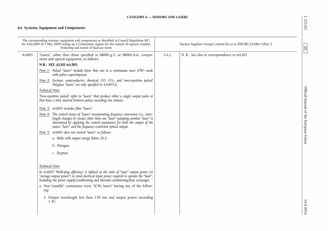
CATEGORY 6 — SENSORS AND LASERS
6A Systems, Equipment and Components
The corresponding systems, equipment and components as identified in Council Regulation (EC) No 428/2009 of 5 May 2009 setting up a Community regime for the control of exports, transfer,
brokering and transit of dual-use items Nuclear Suppliers Group's control list as in INFCIRC/254/Rev.9/Part 2
6A005 “Lasers”, other than those specified in 0B001.g.5. or 0B001.h.6., components and optical equipment, as follows:
N.B.: SEE ALSO 6A205. Note 1: Pulsed “lasers” include those that run in a continuous wave (CW) mode
with pulses superimposed.
Note 2: Excimer, semiconductor, chemical, CO, CO2, and ‘non-repetitive pulsed’ Nd:glass “lasers” are only specified in 6A005.d.
Technical Note:
‘Non-repetitive pulsed’ refers to “lasers” that produce either a single output pulse or that have a time interval between pulses exceeding one minute.
Note 3: 6A005 includes fibre “lasers”.
Note 4: The control status of “lasers” incorporating frequency conversion (i.e., wavelength change) by means other than one “laser” pumping another “laser” is determined by applying the control parameters for both the output of the source “laser” and the frequency-converted optical output.
Note 5: 6A005 does not control “lasers” as follows:
a. Ruby with output energy below 20 J;
b. Nitrogen;
c. Krypton.
Technical Note:
In 6A005 ‘Wall-plug efficiency’ is defined as the ratio of “laser” output power (or “average output power”) to total electrical input power required to operate the “laser”, including the power supply/conditioning and thermal conditioning/heat exchanger.
a. Non-“tunable” continuous wave “(CW) lasers” having any of the following:
1. Output wavelength less than 150 nm and output power exceeding 1 W;
3.A.2 N. B. See also in correspondence to 6A205
16.8.2016 L 221/82
Official Journal of the European U
nion EN

2. Output wavelength of 150 nm or more but not exceeding 510 nm and output power exceeding 30 W;
Note: 6A005.a.2. does not control Argon “lasers” having an output power equal to or less than 50 W.
3. Output wavelength exceeding 510 nm but not exceeding 540 nm and any of the following:
a. Single transverse mode output and output power exceeding 50 W; or
b. Multiple transverse mode output and output power exceeding 150 W;
4. Output wavelength exceeding 540 nm but not exceeding 800 nm and output power exceeding 30 W;
5. Output wavelength exceeding 800 nm but not exceeding 975 nm and any of the following:
a. Single transverse mode output and output power exceeding 50 W; or
b. Multiple transverse mode output and output power exceeding 80 W;
6. Output wavelength exceeding 975 nm but not exceeding 1 150 nm and any of the following:
a. Single transverse mode and output power exceeding 200 W; or
b. Multiple transverse mode output and any of the following:
1. ‘Wall-plug efficiency’ exceeding 18 % and output power exceeding 500 W; or
2. Output power exceeding 2 kW;
Note 1: 6A005.a.6.b. does not control multiple transverse mode, industrial “lasers” with output power exceeding 2 kW and not exceeding 6 kW with a total mass greater than 1 200 kg. For the purpose of this note, total mass includes all components required to operate the “laser”, e.g., “laser”, power supply, heat exchanger, but excludes external optics for beam conditioning and/or delivery.
16.8.2016 L 221/83
Official Journal of the European U
nion EN
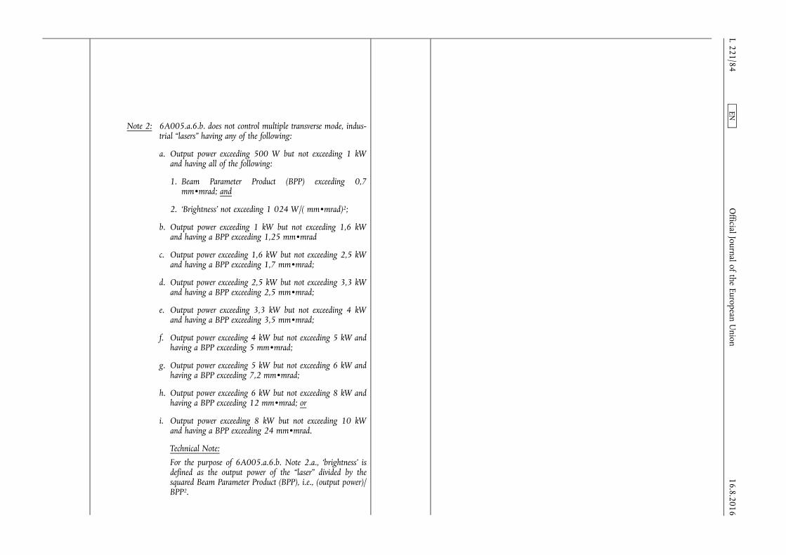
Note 2: 6A005.a.6.b. does not control multiple transverse mode, industrial “lasers” having any of the following:
a. Output power exceeding 500 W but not exceeding 1 kW and having all of the following:
1. Beam Parameter Product (BPP) exceeding 0,7 mm•mrad; and
2. ‘Brightness’ not exceeding 1 024 W/( mm•mrad)2;
b. Output power exceeding 1 kW but not exceeding 1,6 kW and having a BPP exceeding 1,25 mm•mrad
c. Output power exceeding 1,6 kW but not exceeding 2,5 kW and having a BPP exceeding 1,7 mm•mrad;
d. Output power exceeding 2,5 kW but not exceeding 3,3 kW and having a BPP exceeding 2,5 mm•mrad;
e. Output power exceeding 3,3 kW but not exceeding 4 kW and having a BPP exceeding 3,5 mm•mrad;
f. Output power exceeding 4 kW but not exceeding 5 kW and having a BPP exceeding 5 mm•mrad;
g. Output power exceeding 5 kW but not exceeding 6 kW and having a BPP exceeding 7,2 mm•mrad;
h. Output power exceeding 6 kW but not exceeding 8 kW and having a BPP exceeding 12 mm•mrad; or
i. Output power exceeding 8 kW but not exceeding 10 kW and having a BPP exceeding 24 mm•mrad.
Technical Note:
For the purpose of 6A005.a.6.b. Note 2.a., ‘brightness’ is defined as the output power of the “laser” divided by the squared Beam Parameter Product (BPP), i.e., (output power)/ BPP2.
16.8.2016 L 221/84
Official Journal of the European U
nion EN
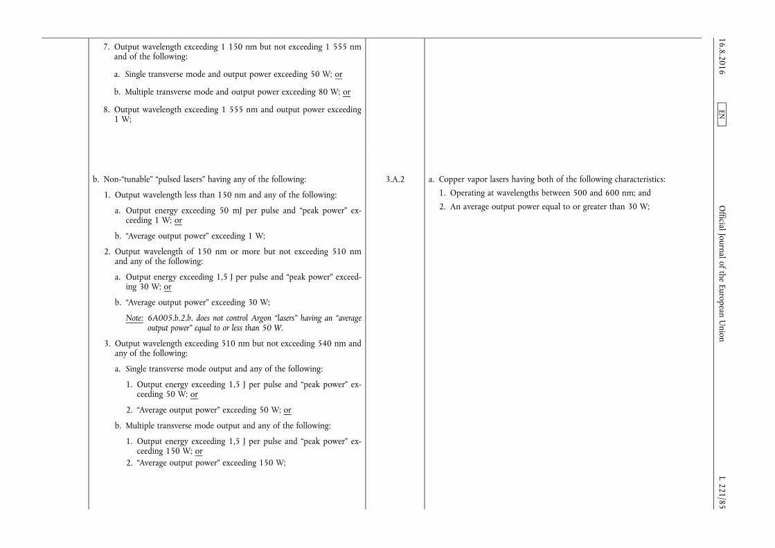
7. Output wavelength exceeding 1 150 nm but not exceeding 1 555 nm and of the following:
a. Single transverse mode and output power exceeding 50 W; or
b. Multiple transverse mode and output power exceeding 80 W; or
8. Output wavelength exceeding 1 555 nm and output power exceeding 1 W;
b. Non-“tunable” “pulsed lasers” having any of the following:
1. Output wavelength less than 150 nm and any of the following:
a. Output energy exceeding 50 mJ per pulse and “peak power” exceeding 1 W; or
b. “Average output power” exceeding 1 W;
2. Output wavelength of 150 nm or more but not exceeding 510 nm and any of the following:
a. Output energy exceeding 1,5 J per pulse and “peak power” exceeding 30 W; or
b. “Average output power” exceeding 30 W;
Note: 6A005.b.2.b. does not control Argon “lasers” having an “average output power” equal to or less than 50 W.
3. Output wavelength exceeding 510 nm but not exceeding 540 nm and any of the following:
a. Single transverse mode output and any of the following:
1. Output energy exceeding 1,5 J per pulse and “peak power” exceeding 50 W; or
2. “Average output power” exceeding 50 W; or
b. Multiple transverse mode output and any of the following:
1. Output energy exceeding 1,5 J per pulse and “peak power” exceeding 150 W; or
2. “Average output power” exceeding 150 W;
3.A.2 a. Copper vapor lasers having both of the following characteristics:
1. Operating at wavelengths between 500 and 600 nm; and
2. An average output power equal to or greater than 30 W;
16.8.2016 L 221/85
Official Journal of the European U
nion EN

4. Output wavelength exceeding 540 nm but not exceeding 800 nm and any of the following:
a. “Pulse duration” less than 1 ps and any of the following:
1. Output energy exceeding 0,005 J per pulse and “peak power” exceeding 5 GW; or
2. “Average output power” exceeding 20 W; or
b. “Pulse duration” equal to or exceeding 1 ps and any of the following:
1. Output energy exceeding 1,5 J per pulse and “peak power” exceeding 30 W; or
2. “Average output power” exceeding 30 W; 5. Output wavelength exceeding 800 nm but not exceeding 975 nm and
any of the following:
a. “Pulse duration” less than 1 ps and any of the following:
1. Output energy exceeding 0,005 J per pulse and “peak power” exceeding 5 GW; or
2. Single transverse mode output and “average output power” exceeding 20 W;
b. “Pulse duration” equal to or exceeding 1 ps and not exceeding 1 µs and any of the following:
1. Output energy exceeding 0,5 J per pulse and “peak power” exceeding 50 W;
2. Single transverse mode output and “average output power” exceeding 20 W; or
3. Multiple transverse mode output and “average output power” exceeding 50 W; or
c. “Pulse duration” exceeding 1 µs and any of the following:
1. Output energy exceeding 2 J per pulse and “peak power” exceeding 50 W;
2. Single transverse mode output and “average output power” exceeding 50 W; or 16.8.2016
L 221/86 O
fficial Journal of the European Union
EN

3. Multiple transverse mode output and “average output power” exceeding 80 W;
6. Output wavelength exceeding 975 nm but not exceeding 1 150 nm and any of the following:
a. “Pulse duration” of less than 1 ps, and any of following:
1. Output “peak power” exceeding 2 GW per pulse;
2. “Average output power” exceeding 10 W; or
3. Output energy exceeding 0,002 J per pulse;
b. “Pulse duration” equal to or exceeding 1 ps and less than 1 ns and any of the following:
1. Output “peak power” exceeding 5 GW per pulse;
2. “Average output power” exceeding 10 W; or
3. Output energy exceeding 0,1 J per pulse;
c. “Pulse duration” equal to or exceeding 1 ns but not exceeding 1 µs, and any of the following:
1. Single transverse mode output and any of the following:
a. “Peak power” exceeding 100 MW;
b. “Average output power” exceeding 20 W limited by design to a maximum pulse repetition frequency less than or equal to 1 kHz;
c. ‘Wall-plug efficiency’ exceeding 12 %, “average output power” exceeding 100 W and capable of operating at a pulse repetition frequency greater than 1 kHz;
d. “Average output power” exceeding 150 W and capable of operating at a pulse repetition frequency greater than 1 kHz; or
e. Output energy exceeding 2 J per pulse; or
2. Multiple transverse mode output and any of the following:
a. “Peak power” exceeding 400 MW;
b. ‘Wall-plug efficiency’ exceeding 18 % and “average output power” exceeding 500 W;
16.8.2016 L 221/87
Official Journal of the European U
nion EN

c. “Average output power” exceeding 2 kW; or
d. Output energy exceeding 4 J per pulse; or
d. “Pulse duration” exceeding 1 µs and any of the following:
1. Single transverse mode output and any of the following:
a. “Peak power” exceeding 500 kW;
b. ‘Wall-plug efficiency’ exceeding 12 % and “average output power” exceeding 100 W; or
c. “Average output power” exceeding 150 W; or
2. Multiple transverse mode output and any of the following:
a. “Peak power” exceeding 1 MW;
b. ‘Wall-plug efficiency’ exceeding 18 % and “average output power” exceeding 500 W; or
c. “Average output power” exceeding 2 kW;
7. Output wavelength exceeding 1 150 nm but not exceeding 1 555 nm, and any of the following:
a. “Pulse duration” not exceeding 1 µs and any of the following:
1. Output energy exceeding 0,5 J per pulse and “peak power” exceeding 50 W;
2. Single transverse mode output and “average output power” exceeding 20 W; or
3. Multiple transverse mode output and “average output power” exceeding 50 W; or
b. “Pulse duration” exceeding 1 µs and any of the following:
1. Output energy exceeding 2 J per pulse and “peak power” exceeding 50 W;
2. Single transverse mode output and “average output power” exceeding 50 W; or
3. Multiple transverse mode output and “average output power” exceeding 80 W; or
16.8.2016 L 221/88
Official Journal of the European U
nion EN

8. Output wavelength exceeding 1 555 nm and any of the following:
a. Output energy exceeding 100 mJ per pulse and “peak power” exceeding 1 W; or
b. “Average output power” exceeding 1 W;
c. “Tunable” “lasers” having any of the following:
1. Output wavelength less than 600 nm and any of the following:
a. Output energy exceeding 50 mJ per pulse and “peak power” exceeding 1 W; or
b. Average or CW output power exceeding 1 W;
Note: 6A005.c.1. does not control dye lasers or other liquid lasers, having a multimode output and a wavelength of 150 nm or more but not exceeding 600 nm and all of the following:
1. Output energy less than 1,5 J per pulse or a “peak power” less than 20 W; and
2. Average or CW output power less than 20 W.
2. Output wavelength of 600 nm or more but not exceeding 1 400 nm, and any of the following:
a. Output energy exceeding 1 J per pulse and “peak power” exceeding 20 W; or
b. Average or CW output power exceeding 20 W; or
3. Output wavelength exceeding 1 400 nm and any of the following:
a. Output energy exceeding 50 mJ per pulse and “peak power” exceeding 1 W; or
b. Average or CW output power exceeding 1 W;
d. Other “lasers”, not specified in 6A005.a., 6A005.b. or 6A005.c. as follows:
1. Semiconductor “lasers” as follows:
Note 1: 6A005.d.1. includes semiconductor “lasers” having optical output connectors (e.g., fibre optic pigtails).
16.8.2016 L 221/89
Official Journal of the European U
nion EN
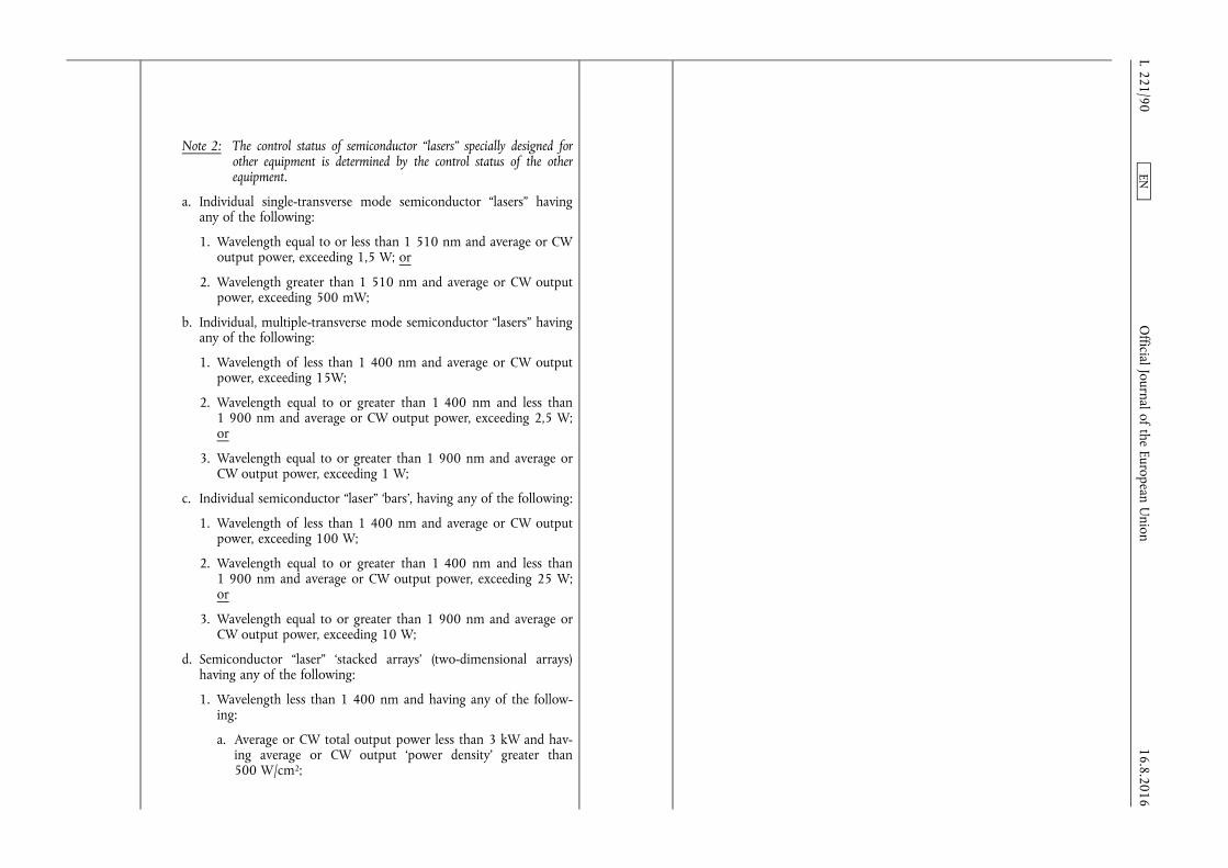
Note 2: The control status of semiconductor “lasers” specially designed for other equipment is determined by the control status of the other equipment.
a. Individual single-transverse mode semiconductor “lasers” having any of the following:
1. Wavelength equal to or less than 1 510 nm and average or CW output power, exceeding 1,5 W; or
2. Wavelength greater than 1 510 nm and average or CW output power, exceeding 500 mW;
b. Individual, multiple-transverse mode semiconductor “lasers” having any of the following:
1. Wavelength of less than 1 400 nm and average or CW output power, exceeding 15W;
2. Wavelength equal to or greater than 1 400 nm and less than 1 900 nm and average or CW output power, exceeding 2,5 W; or
3. Wavelength equal to or greater than 1 900 nm and average or CW output power, exceeding 1 W;
c. Individual semiconductor “laser” ‘bars’, having any of the following:
1. Wavelength of less than 1 400 nm and average or CW output power, exceeding 100 W;
2. Wavelength equal to or greater than 1 400 nm and less than 1 900 nm and average or CW output power, exceeding 25 W; or
3. Wavelength equal to or greater than 1 900 nm and average or CW output power, exceeding 10 W;
d. Semiconductor “laser” ‘stacked arrays’ (two-dimensional arrays) having any of the following:
1. Wavelength less than 1 400 nm and having any of the following:
a. Average or CW total output power less than 3 kW and having average or CW output ‘power density’ greater than 500 W/cm2;
16.8.2016 L 221/90
Official Journal of the European U
nion EN

b. Average or CW total output power equal to or exceeding 3 kW but less than or equal to 5 kW, and having average or CW output ‘power density’ greater than 350 W/cm2;
c. Average or CW total output power exceeding 5 kW;
d. Peak pulsed ‘power density’ exceeding 2 500 W/cm2; or
e. Spatially coherent average or CW total output power, greater than 150 W;
2. Wavelength greater than or equal to 1 400 nm but less than 1 900 nm, and having any of the following:
a. Average or CW total output power less than 250 W and average or CW output ‘power density’ greater than 150 W/cm2;
b. Average or CW total output power equal to or exceeding 250 W but less than or equal to 500 W, and having average or CW output ‘power density’ greater than 50 W/cm2;
c. Average or CW total output power exceeding 500 W;
d. Peak pulsed ‘power density’ exceeding 500 W/cm2; or
e. Spatially coherent average or CW total output power, exceeding 15 W;
3. Wavelength greater than or equal to 1 900 nm and having any of the following:
a. Average or CW output ‘power density’ greater than 50 W/cm2;
b. Average or CW output power greater than 10 W; or
c. Spatially coherent average or CW total output power, exceeding 1,5 W; or
16.8.2016 L 221/91
Official Journal of the European U
nion EN
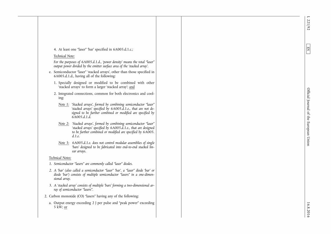
4. At least one “laser” ‘bar’ specified in 6A005.d.1.c.;
Technical Note:
For the purposes of 6A005.d.1.d., ‘power density’ means the total “laser” output power divided by the emitter surface area of the ‘stacked array’.
e. Semiconductor “laser” ‘stacked arrays’, other than those specified in 6A005.d.1.d., having all of the following:
1. Specially designed or modified to be combined with other ‘stacked arrays’ to form a larger ‘stacked array’; and
2. Integrated connections, common for both electronics and cooling;
Note 1: ‘Stacked arrays’, formed by combining semiconductor “laser” ‘stacked arrays’ specified by 6A005.d.1.e., that are not designed to be further combined or modified are specified by 6A005.d.1.d.
Note 2: ‘Stacked arrays’, formed by combining semiconductor “laser” ‘stacked arrays’ specified by 6A005.d.1.e., that are designed to be further combined or modified are specified by 6A005. d.1.e.
Note 3: 6A005.d.1.e. does not control modular assemblies of single ‘bars’ designed to be fabricated into end-to-end stacked linear arrays.
Technical Notes:
1. Semiconductor “lasers” are commonly called “laser” diodes.
2. A ‘bar’ (also called a semiconductor “laser” ‘bar’, a “laser” diode ‘bar’ or diode ‘bar’) consists of multiple semiconductor “lasers” in a one-dimensional array.
3. A ‘stacked array’ consists of multiple ‘bars’ forming a two-dimensional array of semiconductor “lasers”.
2. Carbon monoxide (CO) “lasers” having any of the following:
a. Output energy exceeding 2 J per pulse and “peak power” exceeding 5 kW; or
16.8.2016 L 221/92
Official Journal of the European U
nion EN

b. Average or CW output power exceeding 5 kW;
3. Carbon dioxide (CO2) “lasers” having any of the following:
a. CW output power exceeding 15 kW;
b. Pulsed output with a “pulse duration” exceeding 10 µs and any of the following:
1. “Average output power” exceeding 10 kW; or
2. “Peak power” exceeding 100 kW; or
c. Pulsed output with a “pulse duration” equal to or less than 10 µs and any of the following:
1. Pulse energy exceeding 5 J per pulse; or 2. “Average output power” exceeding 2,5 kW;
4. Excimer “lasers” having any of the following:
a. Output wavelength not exceeding 150 nm and any of the following:
1. Output energy exceeding 50 mJ per pulse; or
2. “Average output power” exceeding 1 W;
b. Output wavelength exceeding 150 nm but not exceeding 190 nm and any of the following:
1. Output energy exceeding 1,5 J per pulse; or
2. “Average output power” exceeding 120 W;
c. Output wavelength exceeding 190 nm but not exceeding 360 nm and any of the following:
1. Output energy exceeding 10 J per pulse; or
2. “Average output power” exceeding 500 W; or
d. Output wavelength exceeding 360 nm and any of the following:
1. Output energy exceeding 1,5 J per pulse; or
2. “Average output power” exceeding 30 W;
N.B.: For excimer “lasers” specially designed for lithography equipment, see 3B001.
3.A.2 h. Pulsed excimer lasers (XeF, XeCl, KrF) having all of the following characteristics:
1. Operating at wavelengths between 240 and 360 nm;
2. A repetition rate greater than 250 Hz; and
3. An average output power greater than 500 W;
16.8.2016 L 221/93
Official Journal of the European U
nion EN

5. “Chemical lasers” as follows:
a. Hydrogen Fluoride (HF) “lasers”;
b. Deuterium Fluoride (DF) “lasers”;
c. “Transfer lasers” as follows:
1. Oxygen Iodine (O2-I) “lasers”;
2. Deuterium Fluoride-Carbon dioxide (DF-CO2) “lasers”;
6. ‘Non-repetitive pulsed’ Nd: glass “lasers” having any of the following:
a. “Pulse duration” not exceeding 1 µs and output energy exceeding 50 J per pulse; or
b. “Pulse duration” exceeding 1 µs and output energy exceeding 100 J per pulse;
Note: ‘Non-repetitive pulsed’ refers to “lasers” that produce either a single output pulse or that have a time interval between pulses exceeding one minute.
e. Components as follows:
1. Mirrors cooled either by ‘active cooling’ or by heat pipe cooling;
Technical Note:
‘Active cooling’ is a cooling technique for optical components using flowing fluids within the subsurface (nominally less than 1 mm below the optical surface) of the optical component to remove heat from the optic.
2. Optical mirrors or transmissive or partially transmissive optical or electro-optical components, other than fused tapered fibre combiners and Multi-Layer Dielectric gratings (MLDs), specially designed for use with specified “lasers”;
Note: Fibre combiners and MLDs are specified in 6A005.e.3.
16.8.2016 L 221/94
Official Journal of the European U
nion EN
3. Fibre laser components as follows:
a. Multimode to multimode fused tapered fibre combiners having all of the following:
1. An insertion loss better (less) than or equal to 0,3 dB maintained at a rated total average or CW output power (excluding output power transmitted through the single mode core if present) exceeding 1 000 W; and
2. Number of input fibres equal to or greater than 3;
b. Single mode to multimode fused tapered fibre combiners having all of the following:
1. An insertion loss better (less) than 0,5 dB maintained at a rated total average or CW output power exceeding 4 600 W;
2. Number of input fibres equal to or greater than 3; and
3. Having any of the following:
a. A Beam Parameter Product (BPP) measured at the output not exceeding 1,5 mm mrad for a number of input fibres less than or equal to 5; or
b. A BPP measured at the output not exceeding 2,5 mm mrad for a number of input fibres greater than 5;
c. MLDs having all of the following:
1. Designed for spectral or coherent beam combination of 5 or more fibre lasers; and
2. CW Laser Induced Damage Threshold (LIDT) greater than or equal to 10 kW/cm2.
f. Optical equipment as follows:
N.B.: For shared aperture optical elements, capable of operating in “Super-High Power Laser” (“SHPL”) applications, see the Military Goods Controls.
16.8.2016 L 221/95
Official Journal of the European U
nion EN

1. Dynamic wavefront (phase) measuring equipment capable of mapping at least 50 positions on a beam wavefront and any of the following:
a. Frame rates equal to or more than 100 Hz and phase discrimination of at least 5 % of the beam's wavelength; or
b. Frame rates equal to or more than 1 000 Hz and phase discrimination of at least 20 % of the beam's wavelength;
2. “Laser” diagnostic equipment capable of measuring “SHPL” system angular beam steering errors of equal to or less than 10 µrad;
3. Optical equipment and components, specially designed for a phased- array “SHPL” system for coherent beam combination to an accuracy of λ/10 at the designed wavelength, or 0,1 µm, whichever is the smaller;
4. Projection telescopes specially designed for use with “SHPL” systems;
g. ‘Laser acoustic detection equipment’ having all of the following:
1. CW laser output power equal to or exceeding 20 mW;
2. Laser frequency stability equal to or better (less) than 10 MHz;
3. Laser wavelengths equal to or exceeding 1 000 nm but not exceeding 2 000 nm;
4. Optical system resolution better (less) than 1 nm; and
5. Optical Signal to Noise ratio equal to or exceeding 103.
Technical Note:
‘Laser acoustic detection equipment’ is sometimes referred to as a Laser Microphone or Particle Flow Detection Microphone.
6A202 Photomultiplier tubes having both of the following characteristics:
a. Photocathode area of greater than 20 cm2; and
b. Anode pulse rise time of less than 1 ns.
5.A.1. Photomultiplier tubes having both of the following characteristics:
a. Photocathode area of greater than 20 cm2; and
b. Anode pulse rise time of less than 1 ns.
16.8.2016 L 221/96
Official Journal of the European U
nion EN
6A203 Cameras and components, other than those specified in 6A003, as follows:
N.B. 1: “Software” specially designed to enhance or release the performance of a camera or imaging device to meet the characteristics of 6A203.a., 6A203.b. or 6A203.c. is specified in 6D203.
N.B. 2: “Technology” in the form of codes or keys to enhance or release the performance of a camera or imaging device to meet the characteristics of 6A203.a., 6A203.b. or 6A203.c is specified in 6E203.
Note:
6A203.a. to 6A203.c. does not control cameras or imaging devices if they have hardware, “software” or “technology” constraints that limit the performance to less than that specified above, provided they meet any of the following:
1. They need to be returned to the original manufacturer to make the enhancements or release the constraints;
2. They require “software” as specified in 6D203 to enhance or release the performance to meet the characteristics of 6A203; or
3. They require “technology” in the form of keys or codes as specified in 6E203 to enhance or release the performance to meet the characteristics of 6A203.
5.B.3. High-speed cameras and imaging devices and components therefor, as follows:
N.B.: “Software” specially designed to enhance or release the performance of cameras or imaging devices to meet the characteristics below is controlled in 5.D.1 and 5.D.2.
6A203 a. Streak cameras, and specially designed components therefor, as follows:
1. Streak cameras with writing speeds greater than 0,5 mm/μs;
2. Electronic streak cameras capable of 50 ns or less time resolution;
3. Streak tubes for cameras specified in 6A203.a.2.;
4. Plug-ins specially designed for use with streak cameras which have modular structures and that enable the performance specifications in 6A203.a.1. or 6A203.a.2.;
5. Synchronizing electronics units, rotor assemblies consisting of turbines, mirrors and bearings specially designed for cameras specified in 6A203.a.1.;
5.B.3.a a. Streak cameras, and specially designed components therefor, as follows:
1. Streak cameras with writing speeds greater than 0,5 mm/μs;
2. Electronic streak cameras capable of 50 ns or less time resolution;
3. Streak tubes for cameras specified in 5.B.3.a.2.;
4. Plug-ins specially designed for use with streak cameras which have modular structures and that enable the performance specifications in 5. B.3.a.1 or 5.B.3.a.2.;
5. Synchronizing electronics units, rotor assemblies consisting of turbines, mirrors and bearings specially designed for cameras specified in 5.B.3.a.1.
16.8.2016 L 221/97
Official Journal of the European U
nion EN
6A203 b. Framing cameras, and specially designed components therefor, as follows:
1. Framing cameras with recording rates greater than 225 000 frames per second;
2. Framing cameras capable of 50 ns or less frame exposure time;
3. Framing tubes and solid-state imaging devices having a fast image gating (shutter) time of 50ns or less specially designed for cameras specified in 6A203.b.1 or 6A203.b.2.;
4. Plug-ins specially designed for use with framing cameras which have modular structures and that enable the performance specifications in 6A203.b.1 or 6A203.b.2.;
5. Synchronizing electronics units, rotor assemblies consisting of turbines, mirrors and bearings specially designed for cameras specified in 6A203.b.1 or 6A203.b.2.;
Technical Note:
In 6A203.b., high speed single frame cameras can be used alone to produce a single image of a dynamic event, or several such cameras can be combined in a sequentially-triggered system to produce multiple images of an event.
5.B.3.b b. Framing cameras and specially designed components therefor as follows:
1. Framing cameras with recording rates greater than 225 000 frames per second;
2. Framing cameras capable of 50 ns or less frame exposure time;
3. Framing tubes and solid-state imaging devices having a fast image gating (shutter) time of 50ns or less specially designed for cameras specified in 5.B.3.b.1 or 5.B.3.b.2.;
4. Plug-ins specially designed for use with framing cameras which have modular structures and that enable the performance specifications in 5. B.3.b.1 or 5.B.3.b.2.;
5. Synchronizing electronics units, rotor assemblies consisting of turbines, mirrors and bearings specially designed for cameras specified in 5.B.3. b.1 or 5.B.3.b.2.
6A203 c. Solid state or electron tube cameras, and specially designed components therefor, as follows:
1. Solid-state cameras or electron tube cameras with a fast image gating (shutter) time of 50 ns or less;
2. Solid-state imaging devices and image intensifiers tubes having a fast image gating (shutter) time of 50 ns or less specially designed for cameras specified in 6A203.c.1.;
3. Electro-optical shuttering devices (Kerr or Pockels cells) with a fast image gating (shutter) time of 50 ns or less;
5.B.3.c c. Solid state or electron tube cameras and specially designed components therefor as follows:
1. Solid-state cameras or electron tube cameras with a fast image gating (shutter) time of 50 ns or less;
2. Solid-state imaging devices and image intensifiers tubes having a fast image gating (shutter) time of 50 ns or less specially designed for cameras specified in 5.B.3.c.1.;
3. Electro-optical shuttering devices (Kerr or Pockels cells) with a fast image gating (shutter) time of 50 ns or less;
16.8.2016 L 221/98
Official Journal of the European U
nion EN

4. Plug-ins specially designed for use with cameras which have modular structures and that enable the performance specifications in 6A203. c.1.
4. Plug-ins specially designed for use with cameras which have modular structures and that enable the performance specifications in 5.B.3.c.1.
Technical Note:
High speed single frame cameras can be used alone to produce a single image of a dynamic event, or several such cameras can be combined in a sequentially-triggered system to produce multiple images of an event.
6A203 d. Radiation-hardened TV cameras, or lenses therefor, specially designed or rated as radiation hardened to withstand a total radiation dose greater than 50 × 103 Gy(silicon) (5 × 10⁶ rad (silicon)) without operational degradation.
Technical Note:
The term Gy(silicon) refers to the energy in Joules per kilogram absorbed by an unshielded silicon sample when exposed to ionising radiation.
1.A.2. Radiation-hardened TV cameras, or lenses therefor, specially designed or rated as radiation hardened to withstand a total radiation dose greater than 5 × 10⁴
Gy (silicon) without operational degradation.
Technical Note:
The term Gy (silicon) refers to the energy in Joules per kilogram absorbed by an unshielded silicon sample when exposed to ionizing radiation.
6A205 “Lasers”, “laser” amplifiers and oscillators, other than those specified in 0B001.g.5., 0B001.h.6. and 6A005; as follows:
N.B.: For copper vapour lasers, see 6A005.b.
3.A.2. Lasers, laser amplifiers and oscillators as follows:
N.B. See also in correspondence to 6A005
6A205 a. Argon ion “lasers” having both of the following characteristics:
1. Operating at wavelengths between 400 nm and 515 nm; and
2. An average output power greater than 40 W;
3.A.2.b Argon ion lasers having both of the following characteristics:
1. Operating at wavelengths between 400 and 515 nm; and
2. An average output power greater than 40 W;
6A205 b. Tunable pulsed single-mode dye laser oscillators having all of the following characteristics:
1. Operating at wavelengths between 300 nm and 800 nm;
2. An average output power greater than 1 W;
3. A repetition rate greater than 1 kHz; and
4. Pulse width less than 100 ns;
3.A.2.d Tunable pulsed single-mode dye laser oscillators having all of the following characteristics:
1. Operating at wavelengths between 300 and 800 nm;
2. An average output power greater than 1 W;
3. A repetition rate greater than 1 kHz; and
4. Pulse width less than 100 ns;
16.8.2016 L 221/99
Official Journal of the European U
nion EN
6A205 c. Tunable pulsed dye laser amplifiers and oscillators, having all of the following characteristics:
1. Operating at wavelengths between 300 nm and 800 nm;
2. An average output power greater than 30 W;
3. A repetition rate greater than 1 kHz; and
4. Pulse width less than 100 ns;
Note: 6A205.c. does not control single mode oscillators;
3.A.2.e Tunable pulsed dye laser amplifiers and oscillators having all of the following characteristics:
1. Operating at wavelengths between 300 and 800 nm;
2. An average output power greater than 30 W;
3. A repetition rate greater than 1 kHz; and
4. Pulse width less than 100 ns;
Note: Item 3.A.2.e. does not control single mode oscillators.
6A205 d. Pulsed carbon dioxide “lasers” having all of the following characteristics:
1. Operating at wavelengths between 9 000 nm and 11 000 nm;
2. A repetition rate greater than 250 Hz;
3. An average output power greater than 500 W; and
4. Pulse width of less than 200 ns;
3.A.2.g Pulsed carbon dioxide lasers having all of the following characteristics:
1. Operating at wavelengths between 9 000 and 11 000 nm;
2. A repetition rate greater than 250 Hz;
3. An average output power greater than 500 W; and
4. Pulse width of less than 200 ns;
Note: Item 3.A.2.g. does not control the higher power (typically 1 to 5 kW) industrial CO2 lasers used in applications such as cutting and welding, as these latter lasers are either continuous wave or are pulsed with a pulse width greater than 200 ns.
6A205 e. Para-hydrogen Raman shifters designed to operate at 16 µm output wavelength and at a repetition rate greater than 250 Hz;
3.A.2.i. Para-hydrogen Raman shifters designed to operate at 16 mm output wavelength and at a repetition rate greater than 250 Hz.
6A205 f. Neodymium-doped (other than glass) “lasers” with an output wavelength between 1 000 and 1 100 nm having either of the following
1. Pulse-excited and Q-switched with a pulse duration equal to or more than 1 ns, and having either of the following:
a. A single–transverse mode output with an average output power greater than 40 W; or
b. A multiple-transverse mode output having an average power greater than 50 W; or
2. Incorporating frequency doubling to give an output wavelength between 500 and 550 nm with an average output power of more than 40 W;
3.A.2.c. Neodymium-doped (other than glass) lasers with an output wavelength between 1 000 and 1 100 nm having either of the following:
1. Pulse-excited and Q-switched with a pulse duration equal to or greater than 1 ns, and having either of the following:
a. A single-transverse mode output with an average output power greater than 40 W; or
b. A multiple-transverse mode output with an average output power greater than 50 W;
or
2. Incorporating frequency doubling to give an output wavelength between 500 and 550 nm with an average output power of greater than 40 W;
16.8.2016 L 221/100
Official Journal of the European U
nion EN
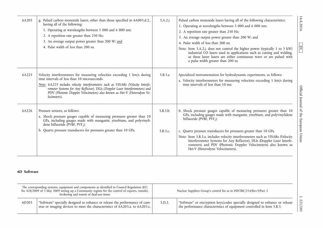
6A205 g. Pulsed carbon monoxide lasers, other than those specified in 6A005.d.2., having all of the following:
1. Operating at wavelengths between 5 000 and 6 000 nm;
2. A repetition rate greater than 250 Hz;
3. An average output power greater than 200 W; and
4. Pulse width of less than 200 ns.
3.A.2.j Pulsed carbon monoxide lasers having all of the following characteristics:
1. Operating at wavelengths between 5 000 and 6 000 nm;
2. A repetition rate greater than 250 Hz;
3. An average output power greater than 200 W; and
4. Pulse width of less than 200 ns;
Note: Item 3.A.2.j. does not control the higher power (typically 1 to 5 kW) industrial CO lasers used in applications such as cutting and welding, as these latter lasers are either continuous wave or are pulsed with a pulse width greater than 200 ns
6A225 Velocity interferometers for measuring velocities exceeding 1 km/s during time intervals of less than 10 microseconds.
Note: 6A225 includes velocity interferometers such as VISARs (Velocity Interferometer Systems for Any Reflector), DLIs (Doppler Laser Interferometers) and PDV (Photonic Doppler Velocimeters) also known as Het-V (Heterodyne Velocimeters).
5.B.5.a Specialized instrumentation for hydrodynamic experiments, as follows:
a. Velocity interferometers for measuring velocities exceeding 1 km/s during time intervals of less than 10 ms;
6A226 Pressure sensors, as follows:
a. Shock pressure gauges capable of measuring pressures greater than 10 GPa, including gauges made with manganin, ytterbium, and polyvinylidene bifluoride (PVBF, PVF2);
b. Quartz pressure transducers for pressures greater than 10 GPa.
5.B.5.b. b. Shock pressure gauges capable of measuring pressures greater than 10 GPa, including gauges made with manganin, ytterbium, and polyvinylidene bifluoride (PVBF, PVF2);
5.B.5.c. c. Quartz pressure transducers for pressures greater than 10 GPa.
Note: Item 5.B.5.a. includes velocity interferometers such as VISARs (Velocity Interferometer Systems for Any Reflector), DLIs (Doppler Laser Interferometers) and PDV (Photonic Doppler Velocimeters) also known as Het-V (Heterodyne Velocimeters).
6D Software
The corresponding systems, equipment and components as identified in Council Regulation (EC) No 428/2009 of 5 May 2009 setting up a Community regime for the control of exports, transfer,
brokering and transit of dual-use items Nuclear Suppliers Group's control list as in INFCIRC/254/Rev.9/Part 2
6D203 “Software” specially designed to enhance or release the performance of cameras or imaging devices to meet the characteristics of 6A203.a. to 6A203.c.
5.D.2. “Software” or encryption keys/codes specially designed to enhance or release the performance characteristics of equipment controlled in Item 5.B.3.
16.8.2016 L 221/101
Official Journal of the European U
nion EN
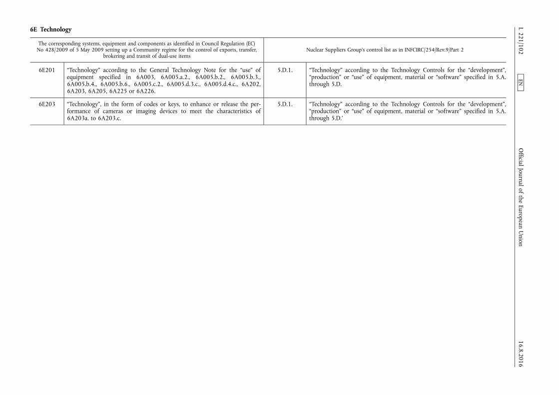
6E Technology
The corresponding systems, equipment and components as identified in Council Regulation (EC) No 428/2009 of 5 May 2009 setting up a Community regime for the control of exports, transfer,
brokering and transit of dual-use items Nuclear Suppliers Group's control list as in INFCIRC/254/Rev.9/Part 2
6E201 “Technology” according to the General Technology Note for the “use” of equipment specified in 6A003, 6A005.a.2., 6A005.b.2., 6A005.b.3., 6A005.b.4., 6A005.b.6., 6A005.c.2., 6A005.d.3.c., 6A005.d.4.c., 6A202, 6A203, 6A205, 6A225 or 6A226.
5.D.1. “Technology” according to the Technology Controls for the “development”, “production” or “use” of equipment, material or “software” specified in 5.A. through 5.D.
6E203 “Technology”, in the form of codes or keys, to enhance or release the performance of cameras or imaging devices to meet the characteristics of 6A203a. to 6A203.c.
5.D.1. “Technology” according to the Technology Controls for the “development”, “production” or “use” of equipment, material or “software” specified in 5.A. through 5.D.’
16.8.2016 L 221/102
Official Journal of the European U
nion EN
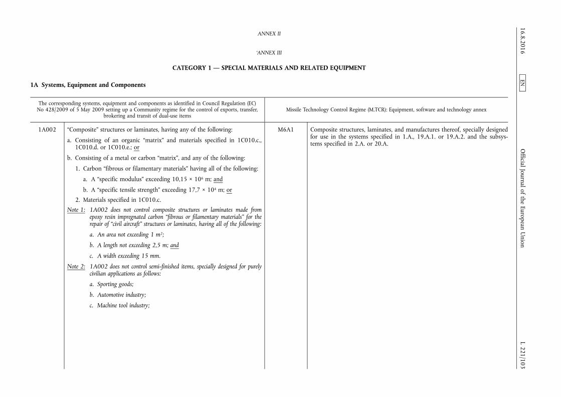
ANNEX II
‘ANNEX III
CATEGORY 1 — SPECIAL MATERIALS AND RELATED EQUIPMENT
1A Systems, Equipment and Components
The corresponding systems, equipment and components as identified in Council Regulation (EC) No 428/2009 of 5 May 2009 setting up a Community regime for the control of exports, transfer,
brokering and transit of dual-use items Missile Technology Control Regime (M.TCR): Equipment, software and technology annex
1A002 “Composite” structures or laminates, having any of the following:
a. Consisting of an organic “matrix” and materials specified in 1C010.c., 1C010.d. or 1C010.e.; or
b. Consisting of a metal or carbon “matrix”, and any of the following:
1. Carbon “fibrous or filamentary materials” having all of the following:
a. A “specific modulus” exceeding 10,15 × 10⁶ m; and
b. A “specific tensile strength” exceeding 17,7 × 10⁴ m; or
2. Materials specified in 1C010.c.
Note 1: 1A002 does not control composite structures or laminates made from epoxy resin impregnated carbon “fibrous or filamentary materials” for the repair of “civil aircraft” structures or laminates, having all of the following:
a. An area not exceeding 1 m2;
b. A length not exceeding 2,5 m; and
c. A width exceeding 15 mm.
Note 2: 1A002 does not control semi-finished items, specially designed for purely civilian applications as follows:
a. Sporting goods;
b. Automotive industry;
c. Machine tool industry;
M6A1 Composite structures, laminates, and manufactures thereof, specially designed for use in the systems specified in 1.A., 19.A.1. or 19.A.2. and the subsystems specified in 2.A. or 20.A.
16.8.2016 L 221/103
Official Journal of the European U
nion EN
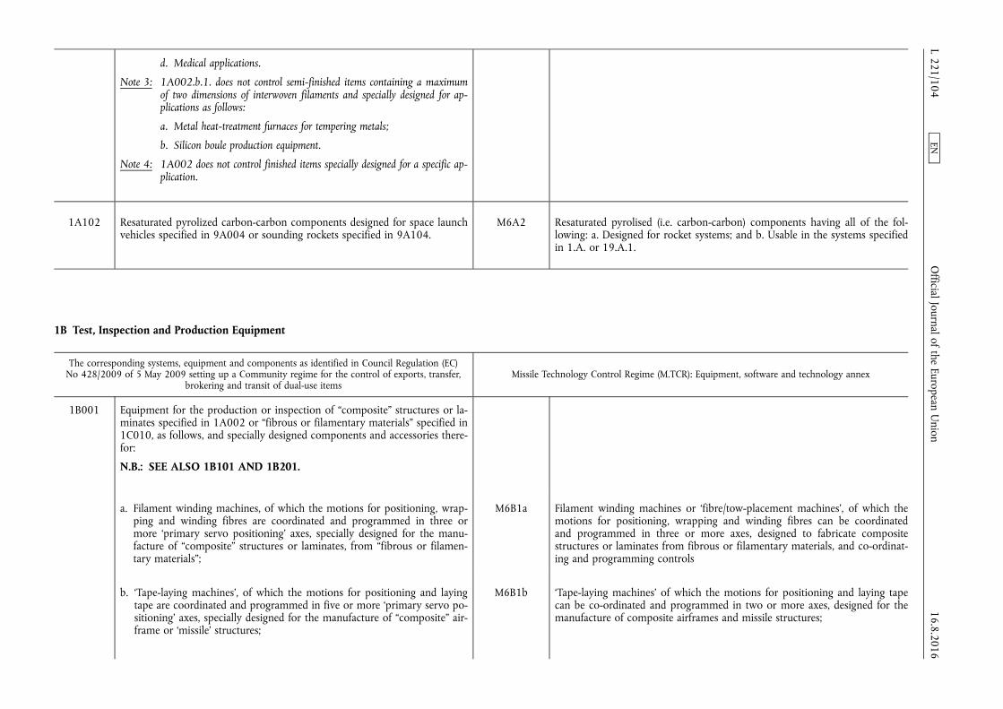
d. Medical applications.
Note 3: 1A002.b.1. does not control semi-finished items containing a maximum of two dimensions of interwoven filaments and specially designed for applications as follows:
a. Metal heat-treatment furnaces for tempering metals;
b. Silicon boule production equipment.
Note 4: 1A002 does not control finished items specially designed for a specific application.
1A102 Resaturated pyrolized carbon-carbon components designed for space launch vehicles specified in 9A004 or sounding rockets specified in 9A104.
M6A2 Resaturated pyrolised (i.e. carbon-carbon) components having all of the following: a. Designed for rocket systems; and b. Usable in the systems specified in 1.A. or 19.A.1.
1B Test, Inspection and Production Equipment
The corresponding systems, equipment and components as identified in Council Regulation (EC) No 428/2009 of 5 May 2009 setting up a Community regime for the control of exports, transfer,
brokering and transit of dual-use items Missile Technology Control Regime (M.TCR): Equipment, software and technology annex
1B001 Equipment for the production or inspection of “composite” structures or laminates specified in 1A002 or “fibrous or filamentary materials” specified in 1C010, as follows, and specially designed components and accessories therefor:
N.B.: SEE ALSO 1B101 AND 1B201.
a. Filament winding machines, of which the motions for positioning, wrapping and winding fibres are coordinated and programmed in three or more ‘primary servo positioning’ axes, specially designed for the manufacture of “composite” structures or laminates, from “fibrous or filamentary materials”;
M6B1a Filament winding machines or ‘fibre/tow-placement machines’, of which the motions for positioning, wrapping and winding fibres can be coordinated and programmed in three or more axes, designed to fabricate composite structures or laminates from fibrous or filamentary materials, and co-ordinating and programming controls
b. ‘Tape-laying machines’, of which the motions for positioning and laying tape are coordinated and programmed in five or more ‘primary servo positioning’ axes, specially designed for the manufacture of “composite” airframe or ‘missile’ structures;
M6B1b ‘Tape-laying machines’ of which the motions for positioning and laying tape can be co-ordinated and programmed in two or more axes, designed for the manufacture of composite airframes and missile structures;
16.8.2016 L 221/104
Official Journal of the European U
nion EN
Note: In 1B001.b., ‘missile’ means complete rocket systems and unmanned aerial vehicle systems.
Technical Note:
For the purposes of 1B001.b., ‘tape-laying machines’ have the ability to lay one or more ‘filament bands’ limited to widths greater than 25 mm and less than or equal to 305 mm, and to cut and restart individual ‘filament band’ courses during the laying process.
Note: For the purposes of 6.B.1.a. and 6.B.1.b., the following definitions apply:
1. A ‘filament band’ is a single continuous width of fully or partially resinimpregnated tape, tow, or fibre. Fully or partially resin-impregnated ‘filament bands’ include those coated with dry powder that tacks upon heating.
2. ‘Fibre/tow-placement machines’ and ‘tape-laying machines’ are machines that perform similar processes that use computer-guided heads to lay one or several ‘filament bands’ onto a mold to create a part or a structure. These machines have the ability to cut and restart individual ‘filament band’ courses during the laying process.
3. ‘Fibre/tow-placement machines’ have the ability to place one or more ‘filament bands’ having widths less than or equal to 25,4 mm. This refers to the minimum width of material the machine can place, regardless of the upper capability of the machine.
4. ‘Tape-laying machines’ have the ability to place one or more ‘filament bands’ having widths less than or equal to 304,8 mm, but cannot place ‘filaments bands’ with a width equal to or less than 25,4 mm. This refers to the minimum width of material the machine can place, regardless of the upper capability of the machine.
c. Multidirectional, multidimensional weaving machines or interlacing machines, including adapters and modification kits, specially designed or modified for weaving, interlacing or braiding fibres, for “composite” structures;
Technical Note:
For the purposes of 1B001.c., the technique of interlacing includes knitting.
M6B1c Multi-directional, multi-dimensional weaving machines or interlacing machines, including adapters and modification kits for weaving, interlacing or braiding fibres to manufacture composite structures;
Note: 6.B.1.c. does not control textile machinery not modified for the end-uses stated.
d. Equipment specially designed or adapted for the production of reinforcement fibres, as follows:
Equipment designed or modified for the production of fibrous or filamentary materials as follows:
1. Equipment for converting polymeric fibres (such as polyacrylonitrile, rayon, pitch or polycarbosilane) into carbon fibres or silicon carbide fibres, including special equipment to strain the fibre during heating;
M6B1d1 1. Equipment for converting polymeric fibres (such as polyacrylonitrile, rayon, or polycarbosilane) including special provision to strain the fibre during heating;
16.8.2016 L 221/105
Official Journal of the European U
nion EN

2. Equipment for the chemical vapour deposition of elements or compounds, on heated filamentary substrates, to manufacture silicon carbide fibres;
M6B1d2 2. Equipment for the vapour deposition of elements or compounds on heated filament substrates;
3. Equipment for the wet-spinning of refractory ceramics (such as aluminium oxide);
M6B1d3 3. Equipment for the wet-spinning of refractory ceramics (such as aluminium oxide)
4. Equipment for converting aluminium containing precursor fibres into alumina fibres by heat treatment;
e. Equipment for producing prepregs specified in 1C010.e. by the hot melt method;
f. Non-destructive inspection equipment specially designed for “composite” materials, as follows: 1. X-ray tomography systems for three dimensional defect inspection;
2. Numerically controlled ultrasonic testing machines of which the motions for positioning transmitters or receivers are simultaneously coordinated and programmed in four or more axes to follow the three dimensional contours of the component under inspection;
g. ‘Tow-placement machines’, of which the motions for positioning and laying tows are coordinated and programmed in two or more ‘primary servo positioning’ axes, specially designed for the manufacture of “composite” airframe or ‘missile’ structures.
Technical Note:
For the purposes of 1B001.g., ‘tow-placement machines’ have the ability to place one or more ‘filament bands’ having widths less than or equal to 25 mm, and to cut and restart individual ‘filament band’ courses during the placement process.
Technical Note:
1. For the purpose of 1B001, ‘primary servo positioning’ axes control, under computer program direction, the position of the end effector (i.e., head) in space relative to the work piece at the correct orientation and direction to achieve the desired process.
2. For the purposes of 1B001., a ‘filament band’ is a single continuous width of fully or partially resin-impregnated tape, tow or fibre.
M6B1e Equipment designed or modified for special fibre surface treatment or for producing prepregs and preforms, including rollers, tension stretchers, coating equipment, cutting equipment and clicker dies.
Note: Examples of components and accessories for the machines specified in 6.B.1. are moulds, mandrels, dies, fixtures and tooling for the preform pressing, curing, casting, sintering or bonding of composite structures, laminates and manufactures thereof
16.8.2016 L 221/106
Official Journal of the European U
nion EN
1B002 Equipment for producing metal alloys, metal alloy powder or alloyed materials, specially designed to avoid contamination and specially designed for use in one of the processes specified in 1C002.c.2.
N.B.: SEE ALSO 1B102.
M4B3d Metal powder “production equipment” usable for the “production”, in a controlled environment, of spherical, spheroidal or atomised materials specified in 4.C.2.c., 4.C.2.d. or 4.C.2.e. Note: 4.B.3.d. includes: a. Plasma generators (high frequency arc-jet) usable for obtaining sputtered or spherical metallic powders with organization of the process in an argon-water environment; b. Electroburst equipment usable for obtaining sputtered or spherical metallic powders with organization of the process in an argon-water environment; c. Equipment usable for the “production” of spherical aluminium powders by powdering a melt in an inert medium (e.g. nitrogen).
Notes:
1. The only batch mixers, continuous mixers, usable for solid propellants or propellants constituents specified in 4.C., and fluid energy mills specified in 4.B., are those specified in 4.B.3.
2. Forms of metal powder “production equipment” not specified in 4.B.3.d. are to be evaluated in accordance with 4.B.2.
1B101 Equipment, other than that specified in 1B001, for the “production” of structural composites as follows; and specially designed components and accessories therefor:
N.B.: SEE ALSO 1B201.
Note: Components and accessories specified in 1B101 include moulds, mandrels, dies, fixtures and tooling for the preform pressing, curing, casting, sintering or bonding of composite structures, laminates and manufactures thereof.
a. Filament winding machines or fibre placement machines, of which the motions for positioning, wrapping and winding fibres can be coordinated and programmed in three or more axes, designed to fabricate composite structures or laminates from fibrous or filamentary materials, and coordinating and programming controls;
M6B1a Filament winding machines or ‘fibre/tow-placement machines’, of which the motions for positioning, wrapping and winding fibres can be coordinated and programmed in three or more axes, designed to fabricate composite structures or laminates from fibrous or filamentary materials, and co-ordinating and programming controls;
b. Tape-laying machines of which the motions for positioning and laying tape and sheets can be coordinated and programmed in two or more axes, designed for the manufacture of composite airframe and “missile” structures;
M6B1b ‘Tape-laying machines’ of which the motions for positioning and laying tape can be co-ordinated and programmed in two or more axes, designed for the manufacture of composite airframes and missile structures;
16.8.2016 L 221/107
Official Journal of the European U
nion EN
Note:
For the purposes of 6.B.1.a. and 6.B.1.b., the following definitions apply:
1. A ‘filament band’ is a single continuous width of fully or partially resinimpregnated tape, tow, or fibre. Fully or partially resin-impregnated ‘filament bands’ include those coated with dry powder that tacks upon heating.
2. ‘Fibre/tow-placement machines’ and ‘tape-laying machines’ are machines that perform similar processes that use computer-guided heads to lay one or several ‘filament bands’ onto a mold to create a part or a structure. These machines have the ability to cut and restart individual ‘filament band’ courses during the laying process.
3. ‘Fibre/tow-placement machines’ have the ability to place one or more ‘filament bands’ having widths less than or equal to 25,4 mm. This refers to the minimum width of material the machine can place, regardless of the upper capability of the machine.
4. ‘Tape-laying machines’ have the ability to place one or more ‘filament bands’ having widths less than or equal to 304,8 mm, but cannot place ‘filaments bands’ with a width equal to or less than 25,4 mm. This refers to the minimum width of material the machine can place, regardless of the upper capability of the machine.
c. Equipment designed or modified for the “production” of “fibrous or filamentary materials” as follows: 1. Equipment for converting polymeric fibres (such as polyacrylonitrile,
rayon or polycarbosilane) including special provision to strain the fibre during heating;
2. Equipment for the vapour deposition of elements or compounds on heated filament substrates;
3. Equipment for the wet-spinning of refractory ceramics (such as aluminium oxide);
M6B1d Equipment designed or modified for the production of fibrous or filamentary materials as follows:
1. Equipment for converting polymeric fibres (such as polyacrylonitrile, rayon, or polycarbosilane) including special provision to strain the fibre during heating;
2. Equipment for the vapour deposition of elements or compounds on heated filament substrates;
3. Equipment for the wet-spinning of refractory ceramics (such as aluminium oxide);
d. Equipment designed or modified for special fibre surface treatment or for producing prepregs and preforms specified in entry 9C110. Note: 1B101.d. includes rollers, tension stretchers, coating equipment, cutting
equipment and clicker dies.
M6B1e Equipment designed or modified for special fibre surface treatment or for producing prepregs and preforms, including rollers, tension stretchers, coating equipment, cutting equipment and clicker dies.
Note: Examples of components and accessories for the machines specified in 6.B.1. are moulds, mandrels, dies, fixtures and tooling for the preform pressing, curing, casting, sintering or bonding of composite structures, laminates and manufactures thereof
16.8.2016 L 221/108
Official Journal of the European U
nion EN

1B102 Metal powder “production equipment”, other than that specified in 1B002, and components as follows:
N.B.: SEE ALSO 1B115.b.
a. Metal powder “production equipment” usable for the “production”, in a controlled environment, of spherical, spheroidal or atomised materials specified in 1C011.a., 1C011.b., 1C111.a.1., 1C111.a.2. or in the Military Goods Controls.
b. Specially designed components for “production equipment” specified in 1B002 or 1B102.a.
Note: 1B102 includes:
a. Plasma generators (high frequency arc-jet) usable for obtaining sputtered or spherical metallic powders with organization of the process in an argon-water environment;
b. Electroburst equipment usable for obtaining sputtered or spherical metallic powders with organization of the process in an argon-water environment;
c. Equipment usable for the “production” of spherical aluminium powders by powdering a melt in an inert medium (e.g. nitrogen).
M4B3d Metal powder “production equipment” usable for the “production”, in a controlled environment, of spherical, spheroidal or atomised materials specified in 4.C.2.c., 4.C.2.d. or 4.C.2.e.
Note: 4.B.3.d. includes:
a. Plasma generators (high frequency arc-jet) usable for obtaining sputtered or spherical metallic powders with organization of the process in an argon- water environment;
b. Electroburst equipment usable for obtaining sputtered or spherical metallic powders with organization of the process in an argon-water environment;
c. Equipment usable for the “production” of spherical aluminium powders by powdering a melt in an inert medium (e.g. nitrogen).
Notes:
1. The only batch mixers, continuous mixers, usable for solid propellants or propellants constituents specified in 4.C., and fluid energy mills specified in 4.B., are those specified in 4.B.3.
2. Forms of metal powder “production equipment” not specified in 4.B.3.d. are to be evaluated in accordance with 4.B.2.
1B115 Equipment, other than that specified in 1B002 or 1B102, for the production of propellant and propellant constituents, as follows, and specially designed components therefor:
a. “Production equipment” for the “production”, handling or acceptance testing of liquid propellants or propellant constituents specified in 1C011.a., 1C011.b., 1C111 or in the Military Goods Controls;
M4B1 “Production equipment”, and specially designed components therefor, for the “production”, handling or acceptance testing of liquid propellants or propellant constituents specified in 4.C.
b. “Production equipment” for the “production”, handling, mixing, curing, casting, pressing, machining, extruding or acceptance testing of solid propellants or propellant constituents specified in 1C011.a., 1C011.b., 1C111 or in the Military Goods Controls.
M4B2 “Production equipment”, other than that described in 4.B.3., and specially designed components therefor, for the production, handling, mixing, curing, casting, pressing, machining, extruding or acceptance testing of solid propellants or propellant constituents specified in 4.C.
16.8.2016 L 221/109
Official Journal of the European U
nion EN

Note: 1B115.b. does not control batch mixers, continuous mixers or fluid energy mills. For the control of batch mixers, continuous mixers and fluid energy mills see 1B117, 1B118 and 1B119.
Note 1: For equipment specially designed for the production of military goods, see the Military Goods Controls.
Note 2: 1B115 does not control equipment for the “production”, handling and acceptance testing of boron carbide.
1B116 Specially designed nozzles for producing pyrolitically derived materials formed on a mould, mandrel or other substrate from precursor gases which decompose in the 1 573 K (1 300 °C) to 3 173 K (2 900 °C) temperature range at pressures of 130 Pa to 20 kPa.
M6B2 Nozzles specially designed for the processes referred to in 6.E.3.
1B117 Batch mixers with provision for mixing under vacuum in the range of zero to 13,326 kPa and with temperature control capability of the mixing chamber and having all of the following, and specially designed components therefor:
a. A total volumetric capacity of 110 litres or more; and
b. At least one ‘mixing/kneading shaft’ mounted off centre.
Note: In 1B117.b. the term ‘mixing/kneading shaft’ does not refer to deagglomerators or knife-spindles.
M4B3a Batch mixers with provision for mixing under vacuum in the range of zero to 13,326 kPa and with temperature control capability of the mixing chamber and having all of the following:
1. A total volumetric capacity of 110 litres or more; and
2. At least one ‘mixing/kneading shaft’ mounted off centre;
Note: In Item 4.B.3.a.2. the term ‘mixing/kneading shaft’ does not refer to deagglomerators or knife-spindles.
1B118 Continuous mixers with provision for mixing under vacuum in the range of zero to 13,326 kPa and with a temperature control capability of the mixing chamber having any of the following, and specially designed components therefor:
a. Two or more mixing/kneading shafts; or
b. A single rotating shaft which oscillates and having kneading teeth/pins on the shaft as well as inside the casing of the mixing chamber.
M4B3b Continuous mixers with provision for mixing under vacuum in the range of zero to 13,326 kPa and with a temperature control capability of the mixing chamber having any of the following:
1. Two or more mixing/kneading shafts; or
2. A single rotating shaft which oscillates and having kneading teeth/pins on the shaft as well as inside the casing of the mixing chamber;
1B119 Fluid energy mills usable for grinding or milling substances specified in 1C011.a., 1C011.b., 1C111 or in the Military Goods Controls, and specially designed components therefor.
M4B3c Fluid energy mills usable for grinding or milling substances specified in 4.C 16.8.2016 L 221/110
Official Journal of the European U
nion EN
1C Materials
The corresponding systems, equipment and components as identified in Council Regulation (EC) No 428/2009 of 5 May 2009 setting up a Community regime for the control of exports, transfer,
brokering and transit of dual-use items Missile Technology Control Regime (M.TCR): Equipment, software and technology annex
1C001 Materials specially designed for use as absorbers of electromagnetic waves, or intrinsically conductive polymers, as follows:
N.B.: SEE ALSO 1C101.
a. Materials for absorbing frequencies exceeding 2 × 10⁸ Hz but less than 3 × 10¹² Hz;
Note 1: 1C001.a. does not control:
a. Hair type absorbers, constructed of natural or synthetic fibres, with non-magnetic loading to provide absorption;
b. Absorbers having no magnetic loss and whose incident surface is non-planar in shape, including pyramids, cones, wedges and convoluted surfaces;
c. Planar absorbers, having all of the following:
1. Made from any of the following:
a. Plastic foam materials (flexible or non-flexible) with carbon- loading, or organic materials, including binders, providing more than 5 % echo compared with metal over a bandwidth exceeding ± 15 % of the centre frequency of the incident energy, and not capable of withstanding temperatures exceeding 450 K (177 °C); or
b. Ceramic materials providing more than 20 % echo compared with metal over a bandwidth exceeding ± 15 % of the centre frequency of the incident energy, and not capable of withstanding temperatures exceeding 800 K (527 °C);
Technical Note:
Absorption test samples for 1C001.a. Note: 1.c.1. should be a square at least 5 wavelengths of the centre frequency on a side and positioned in the far field of the radiating element.
M17C1 Materials for reduced observables such as radar reflectivity, ultraviolet/infrared signatures and acoustic signatures (i.e. stealth technology), for applications usable for the systems specified in 1.A. or 19.A. or the subsystems specified in 2.A.
Notes:
1. 17.C.1. includes structural materials and coatings (including paints), specially designed for reduced or tailored reflectivity or emissivity in the microwave, infrared or ultraviolet spectra.
2. 17.C.1. does not control coatings (including paints) when specially used for thermal control of satellites.
16.8.2016 L 221/111
Official Journal of the European U
nion EN

2. Tensile strength less than 7 × 10⁶ N/m2; and
3. Compressive strength less than 14 × 106 N/m2;
d. Planar absorbers made of sintered ferrite, having all of the following:
1. A specific gravity exceeding 4,4; and
2. A maximum operating temperature of 548 K (275 °C).
Note 2: Nothing in Note 1 to 1C001.a. releases magnetic materials to provide absorption when contained in paint.
b. Materials for absorbing frequencies exceeding 1,5 × 10¹⁴ Hz but less than 3,7 × 10¹⁴ Hz and not transparent to visible light;
Note: 1C001.b. does not control materials, specially designed or formulated for any of the following applications:
a. Laser marking of polymers; or
b. Laser welding of polymers.
c. Intrinsically conductive polymeric materials with a ‘bulk electrical conductivity’ exceeding 10 000 S/m (Siemens per metre) or a ‘sheet (surface) resistivity’ of less than 100 ohms/square, based on any of the following polymers:
1. Polyaniline;
2. Polypyrrole;
3. Polythiophene;
4. Poly phenylene-vinylene; or
5. Poly thienylene-vinylene.
Note: 1C001.c. does not control materials in a liquid form.
Technical Note:
‘Bulk electrical conductivity’ and ‘sheet (surface) resistivity’ should be determined using ASTM D-257 or national equivalents.
1C007 Ceramic powders, non-“composite” ceramic materials, ceramic-“matrix” “composite” materials and precursor materials, as follows:
N.B.: SEE ALSO 1C107.
M6C5 Ceramic composite materials (dielectric constant less than 6 at any frequency from 100 MHz to 100 GHz) for use in missile radomes usable in systems specified in 1.A. or 19.A.1. 16.8.2016
L 221/112 O
fficial Journal of the European Union
EN
a. Ceramic powders of single or complex borides of titanium, having total metallic impurities, excluding intentional additions, of less than 5 000 ppm, an average particle size equal to or less than 5 µm and no more than 10 % of the particles larger than 10 µm;
b. Non-“composite” ceramic materials in crude or semi-fabricated form, composed of borides of titanium with a density of 98 % or more of the theoretical density;
Note: 1C007.b. does not control abrasives.
c. Ceramic-ceramic “composite” materials with a glass or oxide-“matrix” and reinforced with fibres having all of the following:
1. Made from any of the following materials:
a. Si-N;
b. Si-C;
c. Si-Al-O-N; or
d. Si-O-N; and
2. Having a “specific tensile strength” exceeding 12,7 × 10³m;
d. Ceramic-ceramic “composite” materials, with or without a continuous metallic phase, incorporating particles, whiskers or fibres, where carbides or nitrides of silicon, zirconium or boron form the “matrix”;
e. Precursor materials (i.e., special purpose polymeric or metallo-organic materials) for producing any phase or phases of the materials specified in 1C007.c., as follows:
1. Polydiorganosilanes (for producing silicon carbide);
2. Polysilazanes (for producing silicon nitride);
3. Polycarbosilazanes (for producing ceramics with silicon, carbon and nitrogen components);
f. Ceramic-ceramic “composite” materials with an oxide or glass “matrix” reinforced with continuous fibres from any of the following systems:
1. Al2O3 (CAS 1344-28-1); or
2. Si-C-N.
Note: 1C007.f. does not control “composites” containing fibres from these systems with a fibre tensile strength of less than 700 MPa at 1 273 K (1 000 °C) or fibre tensile creep resistance of more than 1 % creep strain at 100 MPa load and 1 273 K (1 000 °C) for 100 hours.
M6C6 Silicon-carbide materials as follows:
a. Bulk machinable silicon-carbide reinforced unfired ceramic usable for nose tips usable in systems specified in 1.A. or 19.A.1.;
Reinforced silicon-carbide ceramic composites usable for nose tips, re-entry vehicles, nozzle flaps, usable in systems specified in 1.A. or 19.A.1.
16.8.2016 L 221/113
Official Journal of the European U
nion EN
1C010 “Fibrous or filamentary materials”, as follows:
N.B.: SEE ALSO 1C210 AND 9C110.
a. Organic “fibrous or filamentary materials”, having all of the following:
1. “Specific modulus” exceeding 12,7 × 10⁶ m; and
2. “Specific tensile strength” exceeding 23,5 × 10⁴ m;
Note: 1C010.a. does not control polyethylene.
b. Carbon “fibrous or filamentary materials”, having all of the following:
1. “Specific modulus” exceeding 14,65 × 10⁶ m; and
2. “Specific tensile strength” exceeding 26,82 × 10⁴ m;
Note: 1C010.b. does not control:
a. “Fibrous or filamentary materials”, for the repair of “civil aircraft” structures or laminates, having all of the following:
1. An area not exceeding 1 m2;
2. A length not exceeding 2,5 m; and
3. A width exceeding 15 mm.
b. Mechanically chopped, milled or cut carbon “fibrous or filamentary materials” 25,0 mm or less in length.
c. Inorganic “fibrous or filamentary materials”, having all of the following:
1. “Specific modulus” exceeding 2,54 × 10⁶ m; and
2. Melting, softening, decomposition or sublimation point exceeding 1 922 K (1 649 °C) in an inert environment;
Note: 1C010.c. does not control:
a. Discontinuous, multiphase, polycrystalline alumina fibres in chopped fibre or random mat form, containing 3 % by weight or more silica, with a “specific modulus” of less than 10 × 106 m;
b. Molybdenum and molybdenum alloy fibres;
c. Boron fibres;
16.8.2016 L 221/114
Official Journal of the European U
nion EN
d. Discontinuous ceramic fibres with a melting, softening, decomposition or sublimation point lower than 2 043 K (1 770 °C) in an inert environment.
Technical Notes:
1. For the purpose of calculating “specific tensile strength”, “specific modulus” or specific weight of “fibrous or filamentary materials” in 1C010.a., 1C010.b. or 1C010.c., the tensile strength and modulus should be determined by using Method A described in ISO 10618 (2004) or national equivalents.
2. Assessing the “specific tensile strength”, “specific modulus” or specific weight of non-unidirectional “fibrous or filamentary materials” (e.g., fabrics, random mats or braids) in 1C010. is to be based on the mechanical properties of the constituent unidirectional monofilaments (e.g., monofilaments, yarns, rovings or tows) prior to processing into the non-unidirectional “fibrous or filamentary materials”.
d. “Fibrous or filamentary materials”, having any of the following:
1. Composed of any of the following:
a. Polyetherimides specified in 1C008.a.; or
b. Materials specified in 1C008.b. to 1C008.f.; or
2. Composed of materials specified in 1C010.d.1.a. or 1C010.d.1.b. and “commingled” with other fibres specified in 1C010.a., 1C010.b. or 1C010.c.;
e. Fully or partially resin-impregnated or pitch-impregnated “fibrous or filamentary materials” (prepregs), metal or carbon-coated “fibrous or filamentary materials” (preforms) or “carbon fibre preforms”, having all of the following:
1. Having any of the following:
a. Inorganic “fibrous or filamentary materials” specified in 1C010.c.; or
b. Organic or carbon “fibrous or filamentary materials”, having all of the following:
1. “Specific modulus” exceeding 10,15 × 10⁶ m; and
2. “Specific tensile strength” exceeding 17,7 × 10⁴ m; and
M6C1 Resin impregnated fibre prepregs and metal coated fibre preforms, for the goods specified in 6.A.1., made either with organic matrix or metal matrix utilising fibrous or filamentary reinforcements having a specific tensile strength greater than 7,62 × 10⁴ m and a specific modulus greater than 3,18 × 10⁶ m.
Note: The only resin impregnated fibre prepregs specified in 6.C.1. are those using resins with a glass transition temperature (Tg), after cure, exceeding 145 °C as determined by ASTM D4065 or national equivalents.
16.8.2016 L 221/115
Official Journal of the European U
nion EN

2. Having any of the following:
a. Resin or pitch, specified in 1C008 or 1C009.b.;
b. ‘Dynamic Mechanical Analysis glass transition temperature (DMA Tg)’ equal to or exceeding 453 K (180 °C) and having a phenolic resin; or
c. ‘Dynamic Mechanical Analysis glass transition temperature (DMA Tg)’ equal to or exceeding 505 K (232 °C) and having a resin or pitch, not specified in 1C008 or 1C009.b., and not being a phenolic resin;
Note 1: Metal or carbon-coated “fibrous or filamentary materials” (preforms) or “carbon fibre preforms”, not impregnated with resin or pitch, are specified by “fibrous or filamentary materials” in 1C010.a., 1C010.b. or 1C010.c.
Note 2: 1C010.e. does not control:
a. Epoxy resin “matrix” impregnated carbon “fibrous or filamentary materials” (prepregs) for the repair of “civil aircraft” structures or laminates, having all the following;
1. An area not exceeding 1 m2;
2. A length not exceeding 2,5 m; and
3. A width exceeding 15 mm.
b. Fully or partially resin-impregnated or pitch-impregnated mechanically chopped, milled or cut carbon “fibrous or filamentary materials” 25,0 mm or less in length when using a resin or pitch other than those specified by 1C008 or 1C009.b.
Technical Note:
The ‘Dynamic Mechanical Analysis glass transition temperature (DMA Tg)’ for materials specified by 1C010.e. is determined using the method described in ASTM D 7028-07, or equivalent national standard, on a dry test specimen. In the case of thermoset materials, degree of cure of a dry test specimen shall be a minimum of 90 % as defined by ASTM E 2160-04 or equivalent national standard.
Technical Notes:
1. In Item 6.C.1. ‘specific tensile strength’ is the ultimate tensile strength in N/m2
divided by the specific weight in N/m3, measured at a temperature of (296 ± 2)K ((23 ± 2)°C) and a relative humidity of (50 ± 5)%.
2. In Item 6.C.1. ‘specific modulus’ is the Young's modulus in N/m2 divided by the specific weight in N/m3, measured at a temperature of (296 ± 2)K ((23 ± 2)°C) and a relative humidity of (50 ± 5)%.
16.8.2016 L 221/116
Official Journal of the European U
nion EN

1C011 Metals and compounds, as follows:
N.B.: SEE ALSO 1C111.
a. Metals in particle sizes of less than 60 µm whether spherical, atomised, spheroidal, flaked or ground, manufactured from material consisting of 99 % or more of zirconium, magnesium and alloys thereof;
Technical Note:
The natural content of hafnium in the zirconium (typically 2 % to 7 %) is counted with the zirconium.
Note: The metals or alloys specified in 1C011.a. are controlled whether or not the metals or alloys are encapsulated in aluminium, magnesium, zirconium or beryllium.
M4C2d Metal powders of any of the following: zirconium (CAS 7440-67-7), beryllium (CAS 7440-41-7), magnesium (CAS 7439-95-4) or alloys of these, if at least 90 % of the total particles by particle volume or weight are made up of particles of less than 60 µm (determined by measurement techniques such as using a sieve, laser diffraction or optical scanning), whether spherical, atomised, spheroidal, flaked or ground, consisting of 97 % by weight or more of any of the above mentioned metals;
Note: In a multimodal particle distribution (e.g. mixtures of different grain sizes) in which one or more modes are controlled, the entire powder mixture is controlled.
Technical Note:
The natural content of hafnium (CAS 7440-58-6) in the zirconium (typically 2 % to 7 %) is counted with the zirconium.
b. Boron or boron alloys, with a particle size of 60 µm or less, as follows:
1. Boron with a purity of 85 % by weight or more;
2. Boron alloys with a boron content of 85 % by weight or more;
Note: The metals or alloys specified in 1C011.b. are controlled whether or not the metals or alloys are encapsulated in aluminium, magnesium, zirconium or beryllium.
c. Guanidine nitrate (CAS 506-93-4);
d. Nitroguanidine (NQ) (CAS 556-88-7).
N.B.: See also Military Goods Controls for metal powders mixed with other substances to form a mixture formulated for military purposes.
M4C2e Metal powders of either boron (CAS 7440-42-8) or boron alloys with a boron content of 85 % or more by weight, if at least 90 % of the total particles by particle volume or weight are made up of particles of less than 60 µm (determined by measurement techniques such as using a sieve, laser diffraction or optical scanning), whether spherical, atomised, spheroidal, flaked or ground;
Note: In a multimodal particle distribution (e.g. mixtures of different grain sizes) in which one or more modes are controlled, the entire powder mixture is controlled.
16.8.2016 L 221/117
Official Journal of the European U
nion EN
1C101 Materials and devices for reduced observables such as radar reflectivity, ultraviolet/infrared signatures and acoustic signatures, other than those specified in 1C001, usable in ‘missiles’, “missile” subsystems or unmanned aerial vehicles specified in 9A012 or 9A112.a.
Note 1: 1C101 includes:
a. Structural materials and coatings specially designed for reduced radar reflectivity;
b. Coatings, including paints, specially designed for reduced or tailored reflectivity or emissivity in the microwave, infrared or ultraviolet regions of the electromagnetic spectrum.
Note 2: 1C101 does not include coatings when specially used for the thermal control of satellites.
Technical Note:
In 1C101 ‘missile’ means complete rocket systems and unmanned aerial vehicle systems capable of a range exceeding 300 km.
M17A1 Devices for reduced observables such as radar reflectivity, ultraviolet/infrared signatures and acoustic signatures (i.e. stealth technology), for applications usable for the systems specified in 1.A. or 19.A. or the subsystems specified in 2.A. or 20.A.
M17C1 Materials for reduced observables such as radar reflectivity, ultraviolet/infrared signatures and acoustic signatures (i.e. stealth technology), for applications usable for the systems specified in 1.A. or 19.A. or the subsystems specified in 2.A.
Notes:
1. 17.C.1. includes structural materials and coatings (including paints), specially designed for reduced or tailored reflectivity or emissivity in the microwave, infrared or ultraviolet spectra.
2. 17.C.1. does not control coatings (including paints) when specially used for thermal control of satellites.
1C102 Resaturated pyrolized carbon-carbon materials designed for space launch vehicles specified in 9A004 or sounding rockets specified in 9A104.
M6C2 Resaturated pyrolised (i.e. carbon-carbon) materials having all of the following: a. Designed for rocket systems; and b. Usable in the systems specified in 1.A. or 19.A.1.
1C107 Graphite and ceramic materials, other than those specified in 1C007, as follows:
a. Fine grain graphites with a bulk density of 1,72 g/cm3 or greater, measured at 288 K (15 °C), and having a grain size of 100 µm or less, usable for rocket nozzles and re-entry vehicle nose tips, which can be machined to any of the following products: 1. Cylinders having a diameter of 120 mm or greater and a length of
50 mm or greater;
2. Tubes having an inner diameter of 65 mm or greater and a wall thickness of 25 mm or greater and a length of 50 mm or greater; or
3. Blocks having a size of 120 mm × 120 mm × 50 mm or greater; N.B.: See also 0C004
M6C3 Fine grain graphites with a bulk density of at least 1,72 g/cc measured at 15 °C and having a grain size of 100 × 10-6 m (100 µm) or less, usable for rocket nozzles and re-entry vehicle nose tips, which can be machined to any of the following products:
a. Cylinders having a diameter of 120 mm or greater and a length of 50 mm or greater;
b. Tubes having an inner diameter of 65 mm or greater and a wall thickness of 25 mm or greater and a length of 50 mm or greater; or
c. Blocks having a size of 120 mm × 120 mm × 50 mm or greater 16.8.2016 L 221/118
Official Journal of the European U
nion EN
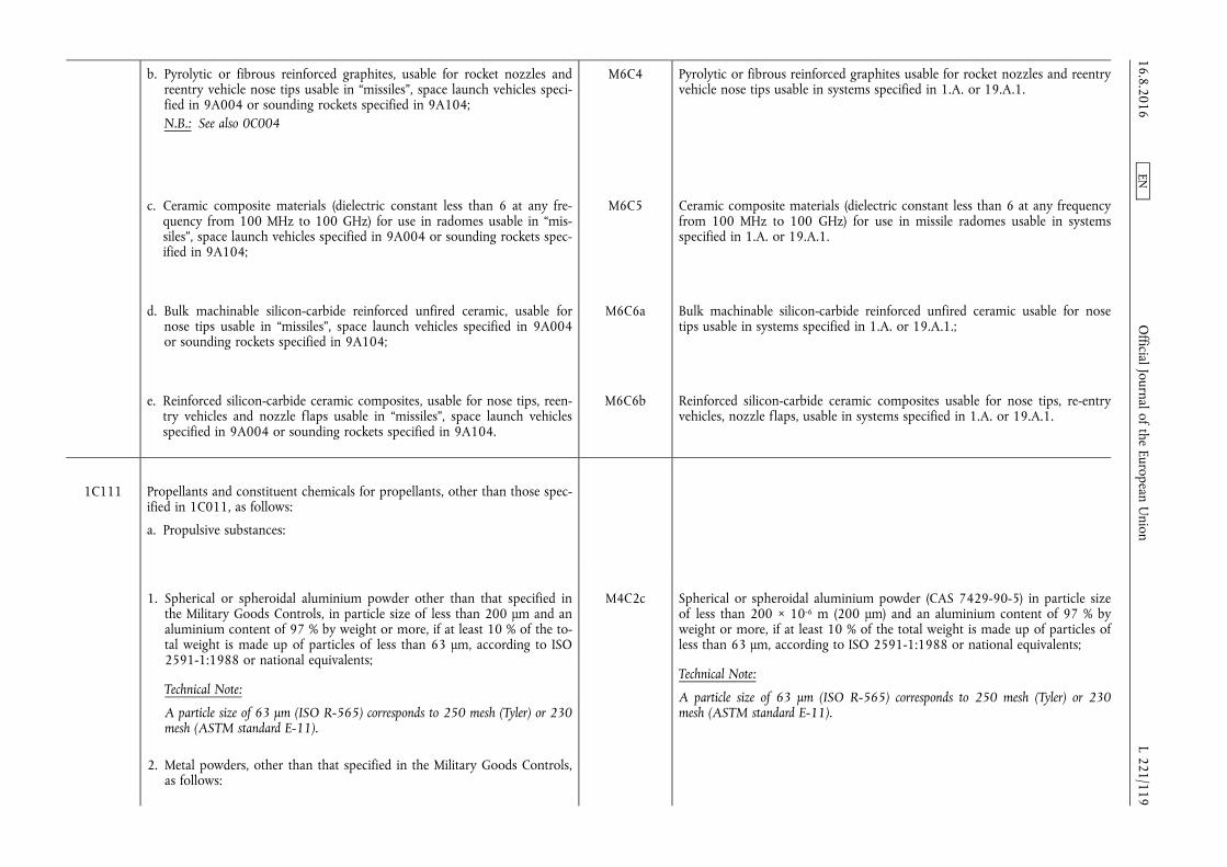
b. Pyrolytic or fibrous reinforced graphites, usable for rocket nozzles and reentry vehicle nose tips usable in “missiles”, space launch vehicles specified in 9A004 or sounding rockets specified in 9A104; N.B.: See also 0C004
M6C4 Pyrolytic or fibrous reinforced graphites usable for rocket nozzles and reentry vehicle nose tips usable in systems specified in 1.A. or 19.A.1.
c. Ceramic composite materials (dielectric constant less than 6 at any frequency from 100 MHz to 100 GHz) for use in radomes usable in “missiles”, space launch vehicles specified in 9A004 or sounding rockets specified in 9A104;
M6C5 Ceramic composite materials (dielectric constant less than 6 at any frequency from 100 MHz to 100 GHz) for use in missile radomes usable in systems specified in 1.A. or 19.A.1.
d. Bulk machinable silicon-carbide reinforced unfired ceramic, usable for nose tips usable in “missiles”, space launch vehicles specified in 9A004 or sounding rockets specified in 9A104;
M6C6a Bulk machinable silicon-carbide reinforced unfired ceramic usable for nose tips usable in systems specified in 1.A. or 19.A.1.;
e. Reinforced silicon-carbide ceramic composites, usable for nose tips, reentry vehicles and nozzle flaps usable in “missiles”, space launch vehicles specified in 9A004 or sounding rockets specified in 9A104.
M6C6b Reinforced silicon-carbide ceramic composites usable for nose tips, re-entry vehicles, nozzle flaps, usable in systems specified in 1.A. or 19.A.1.
1C111 Propellants and constituent chemicals for propellants, other than those specified in 1C011, as follows:
a. Propulsive substances:
1. Spherical or spheroidal aluminium powder other than that specified in the Military Goods Controls, in particle size of less than 200 µm and an aluminium content of 97 % by weight or more, if at least 10 % of the total weight is made up of particles of less than 63 µm, according to ISO 2591-1:1988 or national equivalents;
Technical Note:
A particle size of 63 µm (ISO R-565) corresponds to 250 mesh (Tyler) or 230 mesh (ASTM standard E-11).
2. Metal powders, other than that specified in the Military Goods Controls, as follows:
M4C2c Spherical or spheroidal aluminium powder (CAS 7429-90-5) in particle size of less than 200 × 10-6 m (200 µm) and an aluminium content of 97 % by weight or more, if at least 10 % of the total weight is made up of particles of less than 63 µm, according to ISO 2591-1:1988 or national equivalents;
Technical Note:
A particle size of 63 µm (ISO R-565) corresponds to 250 mesh (Tyler) or 230 mesh (ASTM standard E-11).
16.8.2016 L 221/119
Official Journal of the European U
nion EN

a. Metal powders of zirconium, beryllium or magnesium, or alloys of these metals, if at least 90 % of the total particles by particle volume or weight are made up of particles of less than 60 µm (determined by measurement techniques such as using a sieve, laser diffraction or optical scanning), whether spherical, atomized, spheroidal, flaked or ground, consisting 97 % by weight or more of any of the following: 1. Zirconium;
2. Beryllium; or
3. Magnesium;
Technical Note:
The natural content of hafnium in the zirconium (typically 2 % to 7 %) is counted with the zirconium.
M4C2d Metal powders of any of the following: zirconium (CAS 7440-67-7), beryllium (CAS 7440-41-7), magnesium (CAS 7439-95-4) or alloys of these, if at least 90 % of the total particles by particle volume or weight are made up of particles of less than 60 µm (determined by measurement techniques such as using a sieve, laser diffraction or optical scanning), whether spherical, atomised, spheroidal, flaked or ground, consisting of 97 % by weight or more of any of the above mentioned metals;
Note: In a multimodal particle distribution (e.g. mixtures of different grain sizes) in which one or more modes are controlled, the entire powder mixture is controlled.
Technical Note:
The natural content of hafnium (CAS 7440-58-6) in the zirconium (typically 2 % to 7 %) is counted with the zirconium.
b. Metal powders of either boron or boron alloys with a boron content of 85 % or more by weight, if at least 90 % of the total particles by particle volume or weight are made up of particles of less than 60 µm (determined by measurement techniques such as using a sieve, laser diffraction or optical scanning), whether spherical, atomised, spheroidal, flaked or ground; Note: 1C111a.2.a. and 1C111a.2.b. controls powder mixtures with a multimo
dal particle distribution (e.g. mixtures of different grain sizes) if one or more modes are controlled.
M4C2e Metal powders of either boron (CAS 7440-42-8) or boron alloys with a boron content of 85 % or more by weight, if at least 90 % of the total particles by particle volume or weight are made up of particles of less than 60 µm (determined by measurement techniques such as using a sieve, laser diffraction or optical scanning), whether spherical, atomised, spheroidal, flaked or ground
Note: In a multimodal particle distribution (e.g. mixtures of different grain sizes) in which one or more modes are controlled, the entire powder mixture is controlled.
3. Oxidiser substances usable in liquid propellant rocket engines as follows: a. Dinitrogen trioxide (CAS 10544-73-7);
b. Nitrogen dioxide (CAS 10102-44-0)/dinitrogen tetroxide (CAS 10544-72-6);
c. Dinitrogen pentoxide (CAS 10102-03-1);
d. Mixed Oxides of Nitrogen (MON);
M4C4a Oxidiser substances usable in liquid propellant rocket engines as follows:
1. Dinitrogen trioxide (CAS 10544-73-7)
2. Nitrogen dioxide (CAS 10102-44-0) / dinitrogen tetroxide (CAS 10544- 72-6);
3. Dinitrogen pentoxide (CAS 10102-03-1);
4. Mixed Oxides of Nitrogen (MON); 16.8.2016 L 221/120
Official Journal of the European U
nion EN
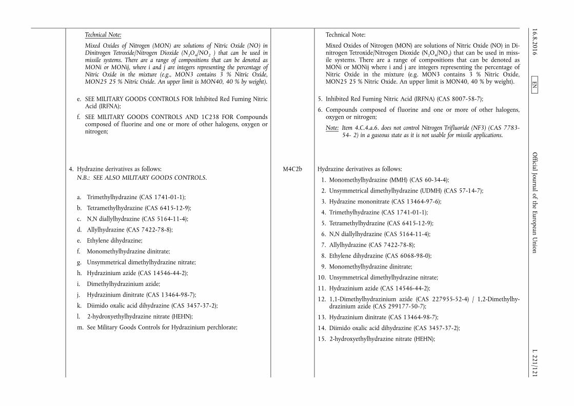
Technical Note:
Mixed Oxides of Nitrogen (MON) are solutions of Nitric Oxide (NO) in Dinitrogen Tetroxide/Nitrogen Dioxide (N2O4/NO2 ) that can be used in missile systems. There are a range of compositions that can be denoted as MONi or MONij, where i and j are integers representing the percentage of Nitric Oxide in the mixture (e.g., MON3 contains 3 % Nitric Oxide, MON25 25 % Nitric Oxide. An upper limit is MON40, 40 % by weight).
e. SEE MILITARY GOODS CONTROLS FOR Inhibited Red Fuming Nitric Acid (IRFNA);
f. SEE MILITARY GOODS CONTROLS AND 1C238 FOR Compounds composed of fluorine and one or more of other halogens, oxygen or nitrogen;
Technical Note:
Mixed Oxides of Nitrogen (MON) are solutions of Nitric Oxide (NO) in Dinitrogen Tetroxide/Nitrogen Dioxide (N2O4/NO2) that can be used in missile systems. There are a range of compositions that can be denoted as MONi or MONij where i and j are integers representing the percentage of Nitric Oxide in the mixture (e.g. MON3 contains 3 % Nitric Oxide, MON25 25 % Nitric Oxide. An upper limit is MON40, 40 % by weight).
5. Inhibited Red Fuming Nitric Acid (IRFNA) (CAS 8007-58-7);
6. Compounds composed of fluorine and one or more of other halogens, oxygen or nitrogen;
Note: Item 4.C.4.a.6. does not control Nitrogen Trifluoride (NF3) (CAS 7783- 54- 2) in a gaseous state as it is not usable for missile applications.
4. Hydrazine derivatives as follows: N.B.: SEE ALSO MILITARY GOODS CONTROLS.
a. Trimethylhydrazine (CAS 1741-01-1);
b. Tetramethylhydrazine (CAS 6415-12-9);
c. N,N diallylhydrazine (CAS 5164-11-4);
d. Allylhydrazine (CAS 7422-78-8);
e. Ethylene dihydrazine;
f. Monomethylhydrazine dinitrate;
g. Unsymmetrical dimethylhydrazine nitrate;
h. Hydrazinium azide (CAS 14546-44-2);
i. Dimethylhydrazinium azide;
j. Hydrazinium dinitrate (CAS 13464-98-7);
k. Diimido oxalic acid dihydrazine (CAS 3457-37-2);
l. 2-hydroxyethylhydrazine nitrate (HEHN);
m. See Military Goods Controls for Hydrazinium perchlorate;
M4C2b Hydrazine derivatives as follows:
1. Monomethylhydrazine (MMH) (CAS 60-34-4);
2. Unsymmetrical dimethylhydrazine (UDMH) (CAS 57-14-7);
3. Hydrazine mononitrate (CAS 13464-97-6);
4. Trimethylhydrazine (CAS 1741-01-1);
5. Tetramethylhydrazine (CAS 6415-12-9);
6. N,N diallylhydrazine (CAS 5164-11-4);
7. Allylhydrazine (CAS 7422-78-8);
8. Ethylene dihydrazine (CAS 6068-98-0);
9. Monomethylhydrazine dinitrate;
10. Unsymmetrical dimethylhydrazine nitrate;
11. Hydrazinium azide (CAS 14546-44-2);
12. 1,1-Dimethylhydrazinium azide (CAS 227955-52-4) / 1,2-Dimethylhydrazinium azide (CAS 299177-50-7);
13. Hydrazinium dinitrate (CAS 13464-98-7);
14. Diimido oxalic acid dihydrazine (CAS 3457-37-2);
15. 2-hydroxyethylhydrazine nitrate (HEHN);
16.8.2016 L 221/121
Official Journal of the European U
nion EN

n. Hydrazinium diperchlorate (CAS 13812-39-0);
o. Methylhydrazine nitrate (MHN) (CAS 29674-96-2);
p. Diethylhydrazine nitrate (DEHN);
q. 3,6-dihydrazino tetrazine nitrate (1,4-dihydrazine nitrate) (DHTN);
16. Hydrazinium perchlorate (CAS 27978-54-7);
17. Hydrazinium diperchlorate (CAS 13812-39-0);
18. Methylhydrazine nitrate (MHN) (CAS 29674-96-2);
19. 1,1-Diethylhydrazine nitrate (DEHN) / 1,2-Diethylhydrazine nitrate (DEHN) (CAS 363453-17-2);
20. 3,6-dihydrazino tetrazine nitrate (DHTN);
Technical note:
3,6-dihydrazino tetrazine nitrate is also referred to as 1,4-dihydrazine nitrate.
5. High energy density materials, other than that specified in the Military Goods Controls, usable in ‘missiles’ or unmanned aerial vehicles specified in 9A012 or 9A112.a.; a. Mixed fuel that incorporate both solid and liquid fuels, such as boron
slurry, having a mass-based energy density of 40 × 106 J/kg or greater;
b. Other high energy density fuels and fuel additives (e.g., cubane, ionic solutions, JP-10) having a volume-based energy density of 37,5 × 10⁹ J/m3 or greater, measured at 20 °C and one atmosphere (101,325 kPa) pressure;
Note: 1C111.a.5.b. does not control fossil refined fuels and biofuels produced from vegetables, including fuels for engines certified for use in civil aviation, unless specially formulated for ‘missiles’ or unmanned aerial vehicles specified in 9A012 or 9A112.a..
Technical Note:
In 1C111.a.5. ‘missile’ means complete rocket systems and unmanned aerial vehicle systems capable of a range exceeding 300 km.
M4C2f High energy density materials, usable in the systems specified in 1.A. or 19. A., as follows:
1. Mixed fuels that incorporate both solid and liquid fuels, such as boron slurry, having a mass- based energy density of 40 × 106 J/kg or greater;
2. Other high energy density fuels and fuel additives (e.g., cubane, ionic solutions, JP-10) having a volume-based energy density of 37,5 × 10⁹ J/m3 or greater, measured at 20 °C and one atmosphere (101,325 kPa) pressure.
Note: Item 4.C.2.f.2. does not control fossil refined fuels and biofuels produced from vegetables, including fuels for engines certified for use in civil aviation, unless specifically formulated for systems specified in 1.A. or 19.A.
6. Hydrazine replacement fuels as follows: a. 2-Dimethylaminoethylazide (DMAZ) (CAS 86147-04-8);
M4C2g Hydrazine replacement fuels as follows: 1. 2-Dimethylaminoethylazide (DMAZ) (CAS 86147-04-8).
16.8.2016 L 221/122
Official Journal of the European U
nion EN

b. Polymeric substances: 1. Carboxy-terminated polybutadiene (including carboxyl-terminated
polybutadiene) (CTPB);
2. Hydroxy-terminated polybutadiene (including hydroxyl-terminated polybutadiene) (HTPB), other than that specified in the Military Goods Controls;
3. Polybutadiene-acrylic acid (PBAA);
4. Polybutadiene-acrylic acid-acrylonitrile (PBAN);
5. Polytetrahydrofuran polyethylene glycol (TPEG);
Technical Note:
Polytetrahydrofuran polyethylene glycol (TPEG) is a block co-polymer of poly 1,4-Butanediol (CAS 110-63-4) and polyethylene glycol (PEG) (CAS 25322-68-3).
6. Polyglycidyl nitrate (PGN or poly-GLYN) (CAS 27814-48-8).
M4C5 Polymeric substances, as follows:
a. Carboxy — terminated polybutadiene (including carboxyl — terminated polybutadiene) (CTPB);
b. Hydroxy — terminated polybutadiene (including hydroxyl — terminated polybutadiene) (HTPB);
c. Glycidyl azide polymer (GAP);
d. Polybutadiene — Acrylic Acid (PBAA);
e. Polybutadiene — Acrylic Acid — Acrylonitrile (PBAN) (CAS 25265-19-4 / CAS 68891-50-9);
f. Polytetrahydrofuran polyethylene glycol (TPEG).
Technical Note:
Polytetrahydrofuran polyethylene glycol (TPEG) is a block co-polymer of poly 1,4-Butanediol (CAS 110-63-4) and polyethylene glycol (PEG) (CAS 25322-68-3).
g. Polyglycidyl nitrate (PGN or poly-GLYN) (CAS 27814-48-8)
c. Other propellant additives and agents:
1. SEE MILITARY GOODS CONTROLS FOR Carboranes, decaboranes, pentaboranes and derivatives thereof;
M4C6c1 Carboranes, decaboranes, pentaboranes and derivatives thereof
2. Triethylene glycol dinitrate (TEGDN) (CAS 111-22-8); M4C6d1 Triethylene glycol dinitrate (TEGDN) (CAS 111-22-8);
3. 2-Nitrodiphenylamine (CAS 119-75-5); M4C6e1 2-Nitrodiphenylamine (CAS 119-75-5);
4. Trimethylolethane trinitrate (TMETN) (CAS 3032-55-1); M4C6d2 Trimethylolethane trinitrate (TMETN) (CAS 3032-55-1);
5. Diethylene glycol dinitrate (DEGDN) (CAS 693-21-0); M4C6d4 Diethylene glycol dinitrate (DEGDN) (CAS 693-21-0)
6. Ferrocene derivatives as follows: a. See Military Goods Controls for catocene;
b. See Military Goods Controls for Ethyl ferrocene;
c. See Military Goods Controls for Propyl ferrocene;
d. See Military Goods Controls for n-butyl ferrocene;
M4C6c2 Ferrocene derivatives, as follows:
a. Catocene (CAS 37206-42-1);
b. Ethyl ferrocene (CAS 1273-89-8);
c. Propyl ferrocene;
d. n-Butyl ferrocene (CAS 31904-29-7);
e. Pentyl ferrocene (CAS 1274-00-6);
f. Dicyclopentyl ferrocene (CAS 125861-17-8);
g. Dicyclohexyl ferrocene;
16.8.2016 L 221/123
Official Journal of the European U
nion EN
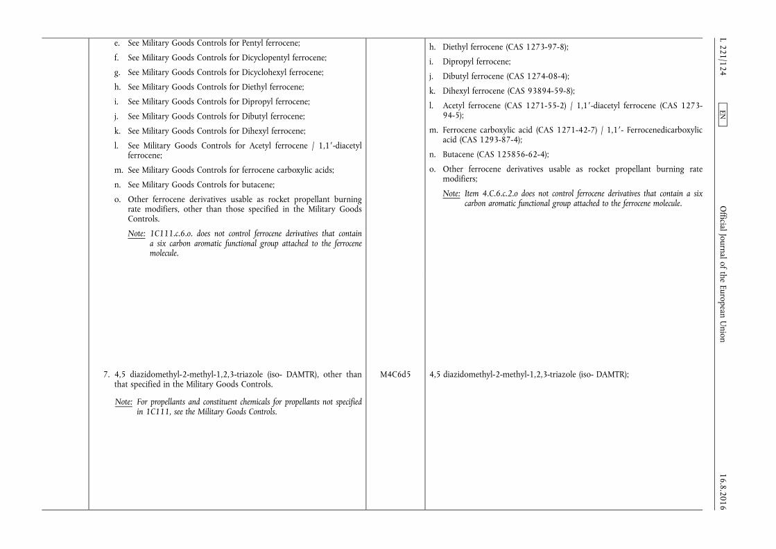
e. See Military Goods Controls for Pentyl ferrocene;
f. See Military Goods Controls for Dicyclopentyl ferrocene;
g. See Military Goods Controls for Dicyclohexyl ferrocene;
h. See Military Goods Controls for Diethyl ferrocene;
i. See Military Goods Controls for Dipropyl ferrocene;
j. See Military Goods Controls for Dibutyl ferrocene;
k. See Military Goods Controls for Dihexyl ferrocene;
l. See Military Goods Controls for Acetyl ferrocene / 1,1′-diacetyl ferrocene;
m. See Military Goods Controls for ferrocene carboxylic acids;
n. See Military Goods Controls for butacene;
o. Other ferrocene derivatives usable as rocket propellant burning rate modifiers, other than those specified in the Military Goods Controls.
Note: 1C111.c.6.o. does not control ferrocene derivatives that contain a six carbon aromatic functional group attached to the ferrocene molecule.
h. Diethyl ferrocene (CAS 1273-97-8);
i. Dipropyl ferrocene;
j. Dibutyl ferrocene (CAS 1274-08-4);
k. Dihexyl ferrocene (CAS 93894-59-8);
l. Acetyl ferrocene (CAS 1271-55-2) / 1,1′-diacetyl ferrocene (CAS 1273- 94-5);
m. Ferrocene carboxylic acid (CAS 1271-42-7) / 1,1′- Ferrocenedicarboxylic acid (CAS 1293-87-4);
n. Butacene (CAS 125856-62-4);
o. Other ferrocene derivatives usable as rocket propellant burning rate modifiers;
Note: Item 4.C.6.c.2.o does not control ferrocene derivatives that contain a six carbon aromatic functional group attached to the ferrocene molecule.
7. 4,5 diazidomethyl-2-methyl-1,2,3-triazole (iso- DAMTR), other than that specified in the Military Goods Controls.
Note: For propellants and constituent chemicals for propellants not specified in 1C111, see the Military Goods Controls.
M4C6d5 4,5 diazidomethyl-2-methyl-1,2,3-triazole (iso- DAMTR);
16.8.2016 L 221/124
Official Journal of the European U
nion EN
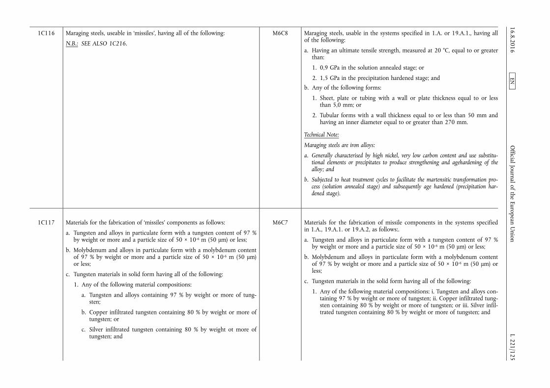
1C116 Maraging steels, useable in ‘missiles’, having all of the following:
N.B.: SEE ALSO 1C216.
M6C8 Maraging steels, usable in the systems specified in 1.A. or 19.A.1., having all of the following:
a. Having an ultimate tensile strength, measured at 20 °C, equal to or greater than:
1. 0,9 GPa in the solution annealed stage; or
2. 1,5 GPa in the precipitation hardened stage; and
b. Any of the following forms:
1. Sheet, plate or tubing with a wall or plate thickness equal to or less than 5,0 mm; or
2. Tubular forms with a wall thickness equal to or less than 50 mm and having an inner diameter equal to or greater than 270 mm.
Technical Note:
Maraging steels are iron alloys:
a. Generally characterised by high nickel, very low carbon content and use substitutional elements or precipitates to produce strengthening and agehardening of the alloy; and
b. Subjected to heat treatment cycles to facilitate the martensitic transformation process (solution annealed stage) and subsequently age hardened (precipitation hardened stage).
1C117 Materials for the fabrication of ‘missiles’ components as follows:
a. Tungsten and alloys in particulate form with a tungsten content of 97 % by weight or more and a particle size of 50 × 10-6 m (50 µm) or less;
b. Molybdenum and alloys in particulate form with a molybdenum content of 97 % by weight or more and a particle size of 50 × 10-6 m (50 µm) or less;
c. Tungsten materials in solid form having all of the following:
1. Any of the following material compositions:
a. Tungsten and alloys containing 97 % by weight or more of tungsten;
b. Copper infiltrated tungsten containing 80 % by weight or more of tungsten; or
c. Silver infiltrated tungsten containing 80 % by weight ot more of tungsten; and
M6C7 Materials for the fabrication of missile components in the systems specified in 1.A., 19.A.1. or 19.A.2, as follows:.
a. Tungsten and alloys in particulate form with a tungsten content of 97 % by weight or more and a particle size of 50 × 10-6 m (50 µm) or less;
b. Molybdenum and alloys in particulate form with a molybdenum content of 97 % by weight or more and a particle size of 50 × 10-6 m (50 µm) or less;
c. Tungsten materials in the solid form having all of the following:
1. Any of the following material compositions: i. Tungsten and alloys containing 97 % by weight or more of tungsten; ii. Copper infiltrated tungsten containing 80 % by weight or more of tungsten; or iii. Silver infiltrated tungsten containing 80 % by weight or more of tungsten; and
16.8.2016 L 221/125
Official Journal of the European U
nion EN
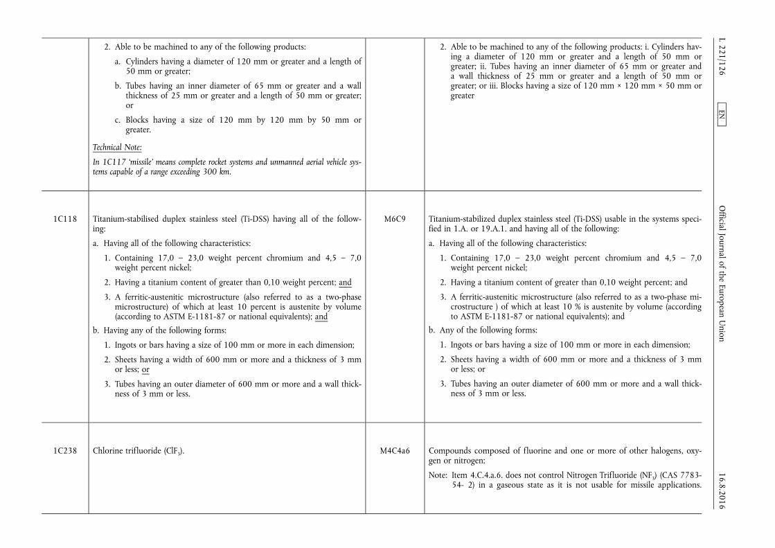
2. Able to be machined to any of the following products:
a. Cylinders having a diameter of 120 mm or greater and a length of 50 mm or greater;
b. Tubes having an inner diameter of 65 mm or greater and a wall thickness of 25 mm or greater and a length of 50 mm or greater; or
c. Blocks having a size of 120 mm by 120 mm by 50 mm or greater.
Technical Note:
In 1C117 ‘missile’ means complete rocket systems and unmanned aerial vehicle systems capable of a range exceeding 300 km.
2. Able to be machined to any of the following products: i. Cylinders having a diameter of 120 mm or greater and a length of 50 mm or greater; ii. Tubes having an inner diameter of 65 mm or greater and a wall thickness of 25 mm or greater and a length of 50 mm or greater; or iii. Blocks having a size of 120 mm × 120 mm × 50 mm or greater
1C118 Titanium-stabilised duplex stainless steel (Ti-DSS) having all of the following:
a. Having all of the following characteristics:
1. Containing 17,0 – 23,0 weight percent chromium and 4,5 – 7,0 weight percent nickel;
2. Having a titanium content of greater than 0,10 weight percent; and
3. A ferritic-austenitic microstructure (also referred to as a two-phase microstructure) of which at least 10 percent is austenite by volume (according to ASTM E-1181-87 or national equivalents); and
b. Having any of the following forms:
1. Ingots or bars having a size of 100 mm or more in each dimension;
2. Sheets having a width of 600 mm or more and a thickness of 3 mm or less; or
3. Tubes having an outer diameter of 600 mm or more and a wall thickness of 3 mm or less.
M6C9 Titanium-stabilized duplex stainless steel (Ti-DSS) usable in the systems specified in 1.A. or 19.A.1. and having all of the following:
a. Having all of the following characteristics:
1. Containing 17,0 – 23,0 weight percent chromium and 4,5 – 7,0 weight percent nickel;
2. Having a titanium content of greater than 0,10 weight percent; and
3. A ferritic-austenitic microstructure (also referred to as a two-phase microstructure ) of which at least 10 % is austenite by volume (according to ASTM E-1181-87 or national equivalents); and
b. Any of the following forms:
1. Ingots or bars having a size of 100 mm or more in each dimension;
2. Sheets having a width of 600 mm or more and a thickness of 3 mm or less; or
3. Tubes having an outer diameter of 600 mm or more and a wall thickness of 3 mm or less.
1C238 Chlorine trifluoride (ClF3). M4C4a6 Compounds composed of fluorine and one or more of other halogens, oxygen or nitrogen;
Note: Item 4.C.4.a.6. does not control Nitrogen Trifluoride (NF3) (CAS 7783- 54- 2) in a gaseous state as it is not usable for missile applications.
16.8.2016 L 221/126
Official Journal of the European U
nion EN

1D Software
The corresponding systems, equipment and components as identified in Council Regulation (EC) No 428/2009 of 5 May 2009 setting up a Community regime for the control of exports, transfer,
brokering and transit of dual-use items Missile Technology Control Regime (M.TCR): Equipment, software and technology annex
1D001 “Software” specially designed or modified for the “development”, “production” or “use” of equipment specified in 1B001 to 1B003.
M6D1 “Software” specially designed or modified for the operation or maintenance of equipment specified in 6.B.1.
1D101 “Software” specially designed or modified for the operation or maintenance of goods specified in1B101, 1B102, 1B115, 1B117, 1B118 or 1B119.
M4D1 “Software” specially designed or modified for the operation or maintenance of equipment specified in 4.B. for the “production” and handling of materials specified in 4.C.
M6D1 “Software” specially designed or modified for the operation or maintenance of equipment specified in 6.B.1.
1D103 “Software” specially designed for analysis of reduced observables such as radar reflectivity, ultraviolet/infrared signatures and acoustic signatures.
M17D1 “Software” specially designed for reduced observables such as radar reflectivity, ultraviolet/infrared signatures and acoustic signatures (i.e. stealth technology), for applications usable for the systems specified in 1.A. or 19.A. or the subsystems specified in 2.A.
Note: 17.D.1. includes “software” specially designed for analysis of signature reduction.
1E Technology
The corresponding systems, equipment and components as identified in Council Regulation (EC) No 428/2009 of 5 May 2009 setting up a Community regime for the control of exports, transfer,
brokering and transit of dual-use items Missile Technology Control Regime (M.TCR): Equipment, software and technology annex
1E001 “Technology” according to the General Technology Note for the “development” or “production” of equipment or materials specified in 1A001.b., 1A001.c., 1A002 to 1A005, 1A006.b., 1A007, 1B or 1C.
M “Technology”, in accordance with the General Technology Note, for the “development”, “production” or “use” of equipment or “software” specified in 1. A., 1.B., or 1.D.
16.8.2016 L 221/127
Official Journal of the European U
nion EN

1E101 “Technology” according to the General Technology Note for the “use” of goods specified in 1A102, 1B001, 1B101, 1B102, 1B115 to 1B119, 1C001, 1C101, 1C107, 1C111 to 1C118, 1D101 or 1D103.
M “Technology”, in accordance with the General Technology Note, for the “development”, “production” or “use” of equipment or “software” specified in 1. A., 1.B., or 1.D.
1E102 “Technology” according to the General Technology Note for the “development” of “software” specified in 1D001, 1D101 or 1D103.
M6E1 “Technology”, in accordance with the General Technology Note, for the “development”, “production” or “use” of equipment, materials or “software” specified in 6.A., 6.B., 6.C. or 6.D.
M17E1 “Technology”, in accordance with the General Technology Note, for the “development”, “production” or “use” of equipment, materials or “software” specified in 17.A., 17.B., 17.C. or 17.D.
Note: 17.E.1. includes databases specially designed for analysis of signature reduction
1E103 [M6E2]“Technology” for the regulation of temperature, pressure or atmosphere in autoclaves or hydroclaves, when used for the “production” of “composites” or partially processed “composites”.
M6E2 “Technical data” (including processing conditions) and procedures for the regulation of temperature, pressures or atmosphere in autoclaves or hydroclaves when used for the production of composites or partially processed composites, usable for equipment or materials specified in 6.A. or 6.C
1E104 “Technology” relating to the “production” of pyrolytically derived materials formed on a mould, mandrel or other substrate from precursor gases which decompose in the 1 573 K (1 300 °C) to 3 173 K (2 900 °C) temperature range at pressures of 130 Pa to 20 kPa.
Note: 1E104 includes “technology” for the composition of precursor gases, flow- rates and process control schedules and parameters.
M6E1
16.8.2016 L 221/128
Official Journal of the European U
nion EN

CATEGORY 2 — MATERRIALS PROCESSING
The corresponding systems, equipment and components as identified in Council Regulation (EC) No 428/2009 of 5 May 2009 setting up a Community regime for the control of exports, transfer,
brokering and transit of dual-use items Missile Technology Control Regime (M.TCR): Equipment, software and technology annex
2A001 Anti-friction bearings and bearing systems, as follows, and components therefor:
N.B.: SEE ALSO 2A101.
Note: 2A001 does not control balls with tolerances specified by the manufacturer in accordance with ISO 3290 as grade 5 or worse.
a. Ball bearings and solid roller bearings, having all tolerances specified by the manufacturer in accordance with ISO 492 Tolerance Class 4 (or national equivalents), or better, and having both rings and rolling elements (ISO 5593), made from monel or beryllium;
Note: 2A001.a. does not control tapered roller bearings.
b. Not used;
c. Active magnetic bearing systems using any of the following:
1. Materials with flux densities of 2,0 T or greater and yield strengths greater than 414 MPa;
2. All-electromagnetic 3D homopolar bias designs for actuators; or
3. High temperature (450 K (177 °C) and above) position sensors.
M3A7 Radial ball bearings having all tolerances specified in accordance with ISO 492 Tolerance Class 2 (or ANSI/ABMA Std 20 Tolerance Class ABEC-9 or other national equivalents), or better and having all the following characteristics:
a) An inner ring bore diameter between 12 and 50 mm;
b) An outer ring outside diameter between 25 and 100 mm; and
c) A width between 10 and 20 mm.
2A101 Radial ball bearings, other than those specified in 2A001, having all tolerances specified in accordance with ISO 492 Tolerance Class 2 (or ANSI/ ABMA Std 20 Tolerance Class ABEC-9 or other national equivalents), or better and having all the following characteristics:
a. An inner ring bore diameter between 12 mm and 50 mm;
b. An outer ring outside diameter between 25 mm and 100 mm; and
c. A width between 10 mm and 20 mm.
M3A7 Radial ball bearings having all tolerances specified in accordance with ISO 492 Tolerance Class 2 (or ANSI/ABMA Std 20 Tolerance Class ABEC-9 or other national equivalents), or better and having all the following characteristics:
a) An inner ring bore diameter between 12 and 50 mm;
b) An outer ring outside diameter between 25 and 100 mm; and
c) A width between 10 and 20 mm.
16.8.2016 L 221/129
Official Journal of the European U
nion EN
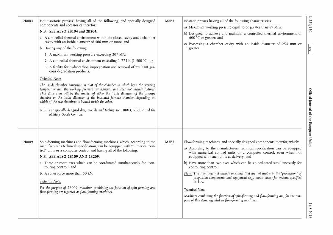
2B004 Hot “isostatic presses” having all of the following, and specially designed components and accessories therefor:
N.B.: SEE ALSO 2B104 and 2B204.
a. A controlled thermal environment within the closed cavity and a chamber cavity with an inside diameter of 406 mm or more; and
b. Having any of the following:
1. A maximum working pressure exceeding 207 MPa;
2. A controlled thermal environment exceeding 1 773 K (1 500 °C); or
3. A facility for hydrocarbon impregnation and removal of resultant gaseous degradation products.
Technical Note:
The inside chamber dimension is that of the chamber in which both the working temperature and the working pressure are achieved and does not include fixtures. That dimension will be the smaller of either the inside diameter of the pressure chamber or the inside diameter of the insulated furnace chamber, depending on which of the two chambers is located inside the other.
N.B.: For specially designed dies, moulds and tooling see 1B003, 9B009 and the Military Goods Controls.
M6B3 Isostatic presses having all of the following characteristics:
a) Maximum working pressure equal to or greater than 69 MPa;
b) Designed to achieve and maintain a controlled thermal environment of 600 °C or greater; and
c) Possessing a chamber cavity with an inside diameter of 254 mm or greater.
2B009 Spin-forming machines and flow-forming machines, which, according to the manufacturer's technical specification, can be equipped with “numerical control” units or a computer control and having all of the following:
N.B.: SEE ALSO 2B109 AND 2B209.
a. Three or more axes which can be coordinated simultaneously for “contouring control”; and
b. A roller force more than 60 kN.
Technical Note:
For the purpose of 2B009, machines combining the function of spin-forming and flow-forming are regarded as flow-forming machines.
M3B3 Flow-forming machines, and specially designed components therefor, which:
a) According to the manufacturers technical specification can be equipped with numerical control units or a computer control, even when not equipped with such units at delivery; and
b) Have more than two axes which can be co-ordinated simultaneously for contouring control.
Note: This item does not include machines that are not usable in the “production” of propulsion components and equipment (e.g. motor cases) for systems specified in 1.A.
Technical Note:
Machines combining the function of spin-forming and flow-forming are, for the purpose of this item, regarded as flow-forming machines. 16.8.2016
L 221/130 O
fficial Journal of the European Union
EN
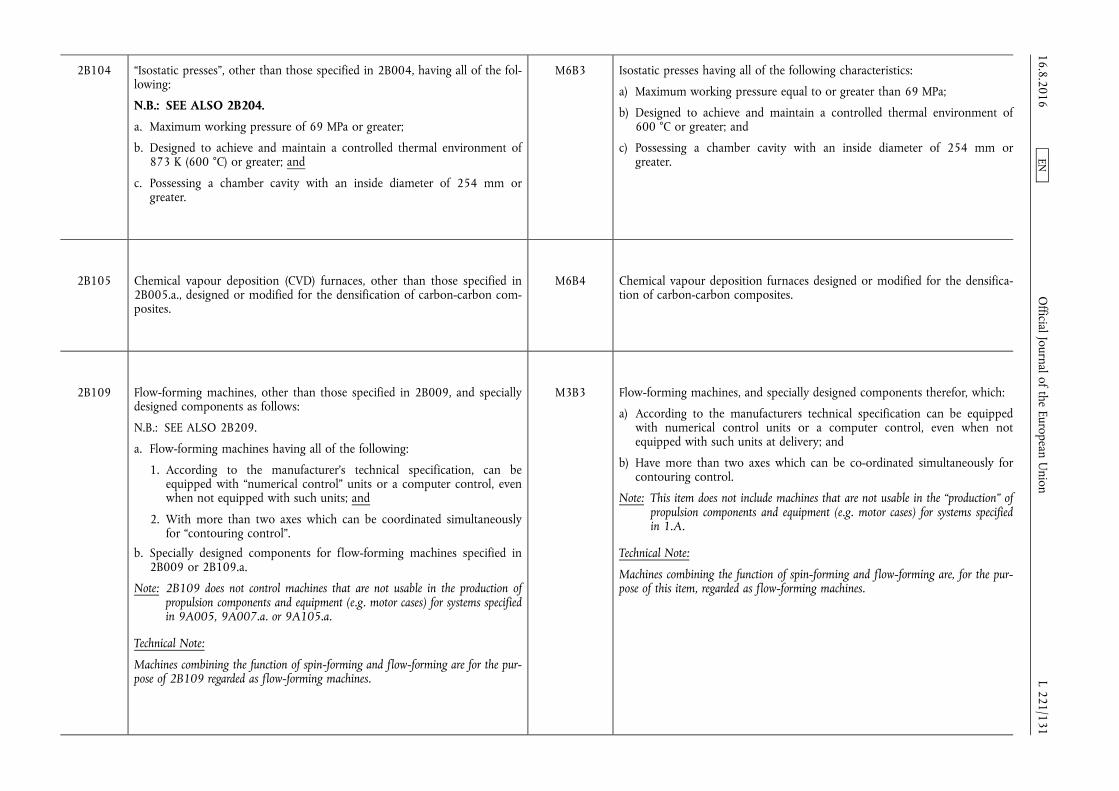
2B104 “Isostatic presses”, other than those specified in 2B004, having all of the following:
N.B.: SEE ALSO 2B204.
a. Maximum working pressure of 69 MPa or greater;
b. Designed to achieve and maintain a controlled thermal environment of 873 K (600 °C) or greater; and
c. Possessing a chamber cavity with an inside diameter of 254 mm or greater.
M6B3 Isostatic presses having all of the following characteristics:
a) Maximum working pressure equal to or greater than 69 MPa;
b) Designed to achieve and maintain a controlled thermal environment of 600 °C or greater; and
c) Possessing a chamber cavity with an inside diameter of 254 mm or greater.
2B105 Chemical vapour deposition (CVD) furnaces, other than those specified in 2B005.a., designed or modified for the densification of carbon-carbon composites.
M6B4 Chemical vapour deposition furnaces designed or modified for the densification of carbon-carbon composites.
2B109 Flow-forming machines, other than those specified in 2B009, and specially designed components as follows:
N.B.: SEE ALSO 2B209.
a. Flow-forming machines having all of the following:
1. According to the manufacturer's technical specification, can be equipped with “numerical control” units or a computer control, even when not equipped with such units; and
2. With more than two axes which can be coordinated simultaneously for “contouring control”.
b. Specially designed components for flow-forming machines specified in 2B009 or 2B109.a.
Note: 2B109 does not control machines that are not usable in the production of propulsion components and equipment (e.g. motor cases) for systems specified in 9A005, 9A007.a. or 9A105.a.
Technical Note:
Machines combining the function of spin-forming and flow-forming are for the purpose of 2B109 regarded as flow-forming machines.
M3B3 Flow-forming machines, and specially designed components therefor, which:
a) According to the manufacturers technical specification can be equipped with numerical control units or a computer control, even when not equipped with such units at delivery; and
b) Have more than two axes which can be co-ordinated simultaneously for contouring control.
Note: This item does not include machines that are not usable in the “production” of propulsion components and equipment (e.g. motor cases) for systems specified in 1.A.
Technical Note:
Machines combining the function of spin-forming and flow-forming are, for the purpose of this item, regarded as flow-forming machines.
16.8.2016 L 221/131
Official Journal of the European U
nion EN
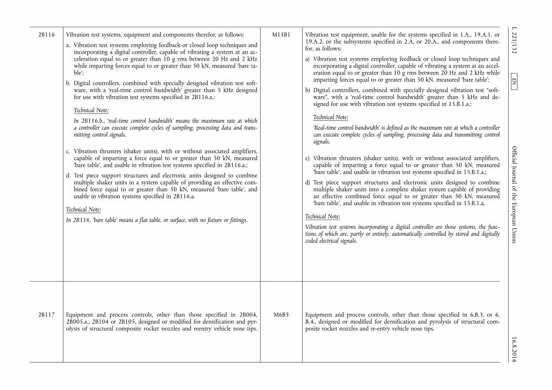
2B116 Vibration test systems, equipment and components therefor, as follows:
a. Vibration test systems employing feedback or closed loop techniques and incorporating a digital controller, capable of vibrating a system at an acceleration equal to or greater than 10 g rms between 20 Hz and 2 kHz while imparting forces equal to or greater than 50 kN, measured ‘bare table’;
b. Digital controllers, combined with specially designed vibration test software, with a ‘real-time control bandwidth’ greater than 5 kHz designed for use with vibration test systems specified in 2B116.a.;
Technical Note:
In 2B116.b., ‘real-time control bandwidth’ means the maximum rate at which a controller can execute complete cycles of sampling, processing data and transmitting control signals.
c. Vibration thrusters (shaker units), with or without associated amplifiers, capable of imparting a force equal to or greater than 50 kN, measured ‘bare table’, and usable in vibration test systems specified in 2B116.a.;
d. Test piece support structures and electronic units designed to combine multiple shaker units in a system capable of providing an effective combined force equal to or greater than 50 kN, measured ‘bare table’, and usable in vibration systems specified in 2B116.a.
Technical Note:
In 2B116, ‘bare table’ means a flat table, or surface, with no fixture or fittings.
M15B1 Vibration test equipment, usable for the systems specified in 1.A., 19.A.1. or 19.A.2. or the subsystems specified in 2.A. or 20.A., and components therefor, as follows:
a) Vibration test systems employing feedback or closed loop techniques and incorporating a digital controller, capable of vibrating a system at an acceleration equal to or greater than 10 g rms between 20 Hz and 2 kHz while imparting forces equal to or greater than 50 kN, measured ‘bare table’;
b) Digital controllers, combined with specially designed vibration test “software”, with a ‘real-time control bandwidth’ greater than 5 kHz and designed for use with vibration test systems specified in 15.B.1.a.;
Technical Note:
‘Real-time control bandwidth’ is defined as the maximum rate at which a controller can execute complete cycles of sampling, processing data and transmitting control signals.
c) Vibration thrusters (shaker units), with or without associated amplifiers, capable of imparting a force equal to or greater than 50 kN, measured ‘bare table’, and usable in vibration test systems specified in 15.B.1.a.;
d) Test piece support structures and electronic units designed to combine multiple shaker units into a complete shaker system capable of providing an effective combined force equal to or greater than 50 kN, measured ‘bare table’, and usable in vibration test systems specified in 15.B.1.a.
Technical Note:
Vibration test systems incorporating a digital controller are those systems, the functions of which are, partly or entirely, automatically controlled by stored and digitally coded electrical signals.
2B117 Equipment and process controls, other than those specified in 2B004, 2B005.a., 2B104 or 2B105, designed or modified for densification and pyrolysis of structural composite rocket nozzles and reentry vehicle nose tips.
M6B5 Equipment and process controls, other than those specified in 6.B.3. or 6. B.4., designed or modified for densification and pyrolysis of structural composite rocket nozzles and re-entry vehicle nose tips.
16.8.2016 L 221/132
Official Journal of the European U
nion EN
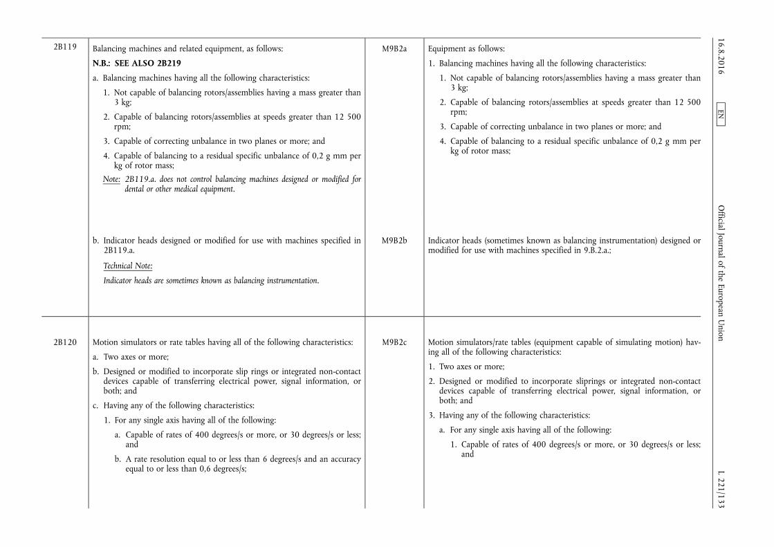
2B119 Balancing machines and related equipment, as follows:
N.B.: SEE ALSO 2B219
a. Balancing machines having all the following characteristics:
1. Not capable of balancing rotors/assemblies having a mass greater than 3 kg;
2. Capable of balancing rotors/assemblies at speeds greater than 12 500 rpm;
3. Capable of correcting unbalance in two planes or more; and
4. Capable of balancing to a residual specific unbalance of 0,2 g mm per kg of rotor mass;
Note: 2B119.a. does not control balancing machines designed or modified for dental or other medical equipment.
M9B2a Equipment as follows:
1. Balancing machines having all the following characteristics:
1. Not capable of balancing rotors/assemblies having a mass greater than 3 kg;
2. Capable of balancing rotors/assemblies at speeds greater than 12 500 rpm;
3. Capable of correcting unbalance in two planes or more; and
4. Capable of balancing to a residual specific unbalance of 0,2 g mm per kg of rotor mass;
b. Indicator heads designed or modified for use with machines specified in 2B119.a.
Technical Note:
Indicator heads are sometimes known as balancing instrumentation.
M9B2b Indicator heads (sometimes known as balancing instrumentation) designed or modified for use with machines specified in 9.B.2.a.;
2B120 Motion simulators or rate tables having all of the following characteristics:
a. Two axes or more;
b. Designed or modified to incorporate slip rings or integrated non-contact devices capable of transferring electrical power, signal information, or both; and
c. Having any of the following characteristics:
1. For any single axis having all of the following:
a. Capable of rates of 400 degrees/s or more, or 30 degrees/s or less; and
b. A rate resolution equal to or less than 6 degrees/s and an accuracy equal to or less than 0,6 degrees/s;
M9B2c Motion simulators/rate tables (equipment capable of simulating motion) having all of the following characteristics:
1. Two axes or more;
2. Designed or modified to incorporate sliprings or integrated non-contact devices capable of transferring electrical power, signal information, or both; and
3. Having any of the following characteristics:
a. For any single axis having all of the following:
1. Capable of rates of 400 degrees/s or more, or 30 degrees/s or less; and
16.8.2016 L 221/133
Official Journal of the European U
nion EN
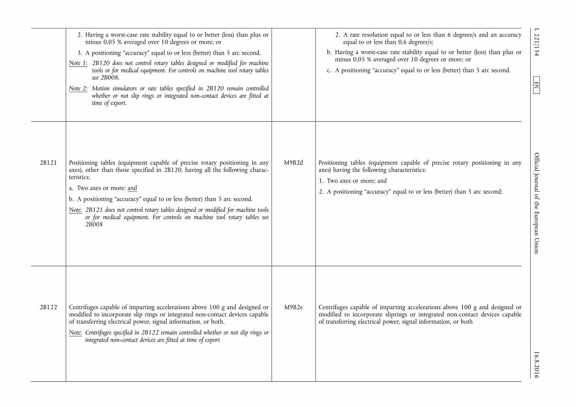
2. Having a worst-case rate stability equal to or better (less) than plus or minus 0,05 % averaged over 10 degrees or more; or
3. A positioning “accuracy” equal to or less (better) than 5 arc second.
Note 1: 2B120 does not control rotary tables designed or modified for machine tools or for medical equipment. For controls on machine tool rotary tables see 2B008.
Note 2: Motion simulators or rate tables specified in 2B120 remain controlled whether or not slip rings or integrated non-contact devices are fitted at time of export.
2. A rate resolution equal to or less than 6 degrees/s and an accuracy equal to or less than 0,6 degrees/s;
b. Having a worst-case rate stability equal to or better (less) than plus or minus 0,05 % averaged over 10 degrees or more; or
c. A positioning “accuracy” equal to or less (better) than 5 arc second.
2B121 Positioning tables (equipment capable of precise rotary positioning in any axes), other than those specified in 2B120, having all the following characteristics:
a. Two axes or more; and
b. A positioning “accuracy” equal to or less (better) than 5 arc second.
Note: 2B121 does not control rotary tables designed or modified for machine tools or for medical equipment. For controls on machine tool rotary tables see 2B008
M9B2d Positioning tables (equipment capable of precise rotary positioning in any axes) having the following characteristics:
1. Two axes or more; and
2. A positioning “accuracy” equal to or less (better) than 5 arc second;
2B122 Centrifuges capable of imparting accelerations above 100 g and designed or modified to incorporate slip rings or integrated non-contact devices capable of transferring electrical power, signal information, or both.
Note: Centrifuges specified in 2B122 remain controlled whether or not slip rings or integrated non-contact devices are fitted at time of export
M9B2e Centrifuges capable of imparting accelerations above 100 g and designed or modified to incorporate sliprings or integrated non-contact devices capable of transferring electrical power, signal information, or both
16.8.2016 L 221/134
Official Journal of the European U
nion EN

2D Software
The corresponding systems, equipment and components as identified in Council Regulation (EC) No 428/2009 of 5 May 2009 setting up a Community regime for the control of exports, transfer,
brokering and transit of dual-use items Missile Technology Control Regime (M.TCR): Equipment, software and technology annex
2D001 “Software”, other than that specified in 2D002, as follows:
a. “Software” specially designed or modified for the “development” or “production” of equipment specified in 2A001 or 2B001
b. “Software” specially designed or modified for the “use” of equipment specified in 2A001.c., 2B001 or 2B003 to 2B009.
Note: 2D001 does not control part programming “software” that generates “numerical control” codes for machining various parts.
M3D SOFTWARE
2D101 “Software” specially designed or modified for the “use” of equipment specified in 2B104, 2B105, 2B109, 2B116, 2B117 or 2B119 to 2B122.
N.B.: SEE ALSO 9D004.
M3D1 “Software” specially designed or modified for the “use” of “production facilities” and flow-forming machines specified in 3.B.1. or 3.B.3.
M6D2 “Software” specially designed or modified for the equipment specified in 6. B.3., 6.B.4. or 6.B.5.
M15D1 “Software” specially designed or modified for the “use” of equipment specified in 15.B. usable for testing systems specified in 1.A., 19.A.1. or 19.A.2. or subsystems specified in 2.A. or 20.A.
2E Technology
The corresponding systems, equipment and components as identified in Council Regulation (EC) No 428/2009 of 5 May 2009 setting up a Community regime for the control of exports, transfer,
brokering and transit of dual-use items Missile Technology Control Regime (M.TCR): Equipment, software and technology annex
2E001 “Technology” according to the General Technology Note for the “development” of equipment or “software” specified in 2A, 2B or 2D.
Note: 2E001 includes “technology” for the integration of probe systems into coordinate measurement machines specified in 2B006.a.
M Means specific information which is required for the “development”, “production” or “use” of a product. The information may take the form of “technical data” or “technical assistance”.
16.8.2016 L 221/135
Official Journal of the European U
nion EN
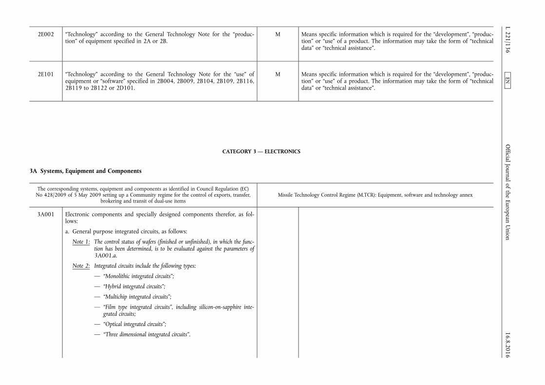
2E002 “Technology” according to the General Technology Note for the “production” of equipment specified in 2A or 2B.
M Means specific information which is required for the “development”, “production” or “use” of a product. The information may take the form of “technical data” or “technical assistance”.
2E101 “Technology” according to the General Technology Note for the “use” of equipment or “software” specified in 2B004, 2B009, 2B104, 2B109, 2B116, 2B119 to 2B122 or 2D101.
M Means specific information which is required for the “development”, “production” or “use” of a product. The information may take the form of “technical data” or “technical assistance”.
CATEGORY 3 — ELECTRONICS
3A Systems, Equipment and Components
The corresponding systems, equipment and components as identified in Council Regulation (EC) No 428/2009 of 5 May 2009 setting up a Community regime for the control of exports, transfer,
brokering and transit of dual-use items Missile Technology Control Regime (M.TCR): Equipment, software and technology annex
3A001 Electronic components and specially designed components therefor, as follows:
a. General purpose integrated circuits, as follows:
Note 1: The control status of wafers (finished or unfinished), in which the function has been determined, is to be evaluated against the parameters of 3A001.a.
Note 2: Integrated circuits include the following types:
— “Monolithic integrated circuits”;
— “Hybrid integrated circuits”;
— “Multichip integrated circuits”;
— “Film type integrated circuits”, including silicon-on-sapphire integrated circuits;
— “Optical integrated circuits”;
— “Three dimensional integrated circuits”.
16.8.2016 L 221/136
Official Journal of the European U
nion EN
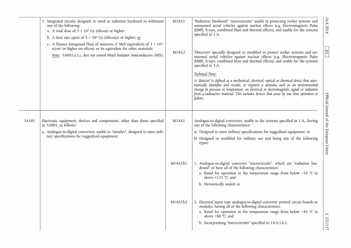
1. Integrated circuits designed or rated as radiation hardened to withstand any of the following: a. A total dose of 5 × 10³ Gy (silicon) or higher;
b. A dose rate upset of 5 × 10⁶ Gy (silicon)/s or higher; or
c. A fluence (integrated flux) of neutrons (1 MeV equivalent) of 5 × 10¹³
n/cm2 or higher on silicon, or its equivalent for other materials;
Note: 3A001.a.1.c. does not control Metal Insulator Semiconductors (MIS).
M18A1 “Radiation Hardened” “microcircuits” usable in protecting rocket systems and unmanned aerial vehicles against nuclear effects (e.g. Electromagnetic Pulse (EMP), X-rays, combined blast and thermal effects), and usable for the systems specified in 1.A.
M18A2 ‘Detectors’ specially designed or modified to protect rocket systems and unmanned aerial vehicles against nuclear effects (e.g. Electromagnetic Pulse (EMP), X-rays, combined blast and thermal effects), and usable for the systems specified in 1.A.
Technical Note:
A ‘detector’ is defined as a mechanical, electrical, optical or chemical device that automatically identifies and records, or registers a stimulus such as an environmental change in pressure or temperature, an electrical or electromagnetic signal or radiation from a radioactive material. This includes devices that sense by one time operation or failure.
3A101 Electronic equipment, devices and components, other than those specified in 3A001, as follows:
a. Analogue-to-digital converters, usable in “missiles”, designed to meet military specifications for ruggedized equipment;
M14A1 Analogue-to-digital converters, usable in the systems specified in 1.A., having any of the following characteristics:
a) Designed to meet military specifications for ruggedised equipment; or
b) Designed or modified for military use and being any of the following types:
M14A1b1 1. Analogue-to-digital converter “microcircuits”, which are “radiation hardened” or have all of the following characteristics: a. Rated for operation in the temperature range from below –54 °C to
above +125 °C; and
b. Hermetically sealed; or
M14A1b2 2. Electrical input type analogue-to-digital converter printed circuit boards or modules, having all of the following characteristics: a. Rated for operation in the temperature range from below –45 °C to
above +80 °C; and
b. Incorporating “microcircuits” specified in 14.A.1.b.1.
16.8.2016 L 221/137
Official Journal of the European U
nion EN
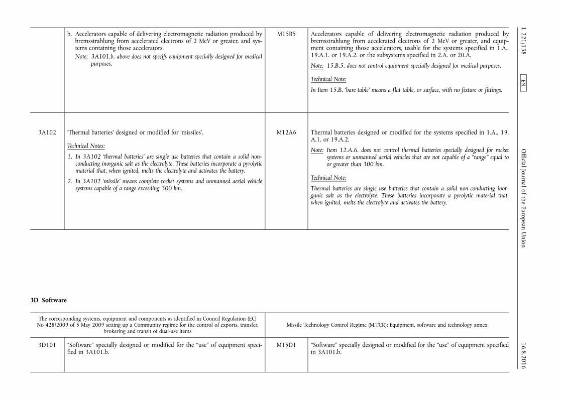
b. Accelerators capable of delivering electromagnetic radiation produced by bremsstrahlung from accelerated electrons of 2 MeV or greater, and systems containing those accelerators. Note: 3A101.b. above does not specify equipment specially designed for medical
purposes.
M15B5 Accelerators capable of delivering electromagnetic radiation produced by bremsstrahlung from accelerated electrons of 2 MeV or greater, and equipment containing those accelerators, usable for the systems specified in 1.A., 19.A.1. or 19.A.2. or the subsystems specified in 2.A. or 20.A.
Note: 15.B.5. does not control equipment specially designed for medical purposes.
Technical Note:
In Item 15.B. ‘bare table’ means a flat table, or surface, with no fixture or fittings.
3A102 ‘Thermal batteries’ designed or modified for ‘missiles’.
Technical Notes:
1. In 3A102 ‘thermal batteries’ are single use batteries that contain a solid non- conducting inorganic salt as the electrolyte. These batteries incorporate a pyrolytic material that, when ignited, melts the electrolyte and activates the battery.
2. In 3A102 ‘missile’ means complete rocket systems and unmanned aerial vehicle systems capable of a range exceeding 300 km.
M12A6 Thermal batteries designed or modified for the systems specified in 1.A., 19. A.1. or 19.A.2.
Note: Item 12.A.6. does not control thermal batteries specially designed for rocket systems or unmanned aerial vehicles that are not capable of a “range” equal to or greater than 300 km.
Technical Note:
Thermal batteries are single use batteries that contain a solid non-conducting inorganic salt as the electrolyte. These batteries incorporate a pyrolytic material that, when ignited, melts the electrolyte and activates the battery.
3D Software
The corresponding systems, equipment and components as identified in Council Regulation (EC) No 428/2009 of 5 May 2009 setting up a Community regime for the control of exports, transfer,
brokering and transit of dual-use items Missile Technology Control Regime (M.TCR): Equipment, software and technology annex
3D101 “Software” specially designed or modified for the “use” of equipment specified in 3A101.b.
M15D1 “Software” specially designed or modified for the “use” of equipment specified in 3A101.b.
16.8.2016 L 221/138
Official Journal of the European U
nion EN
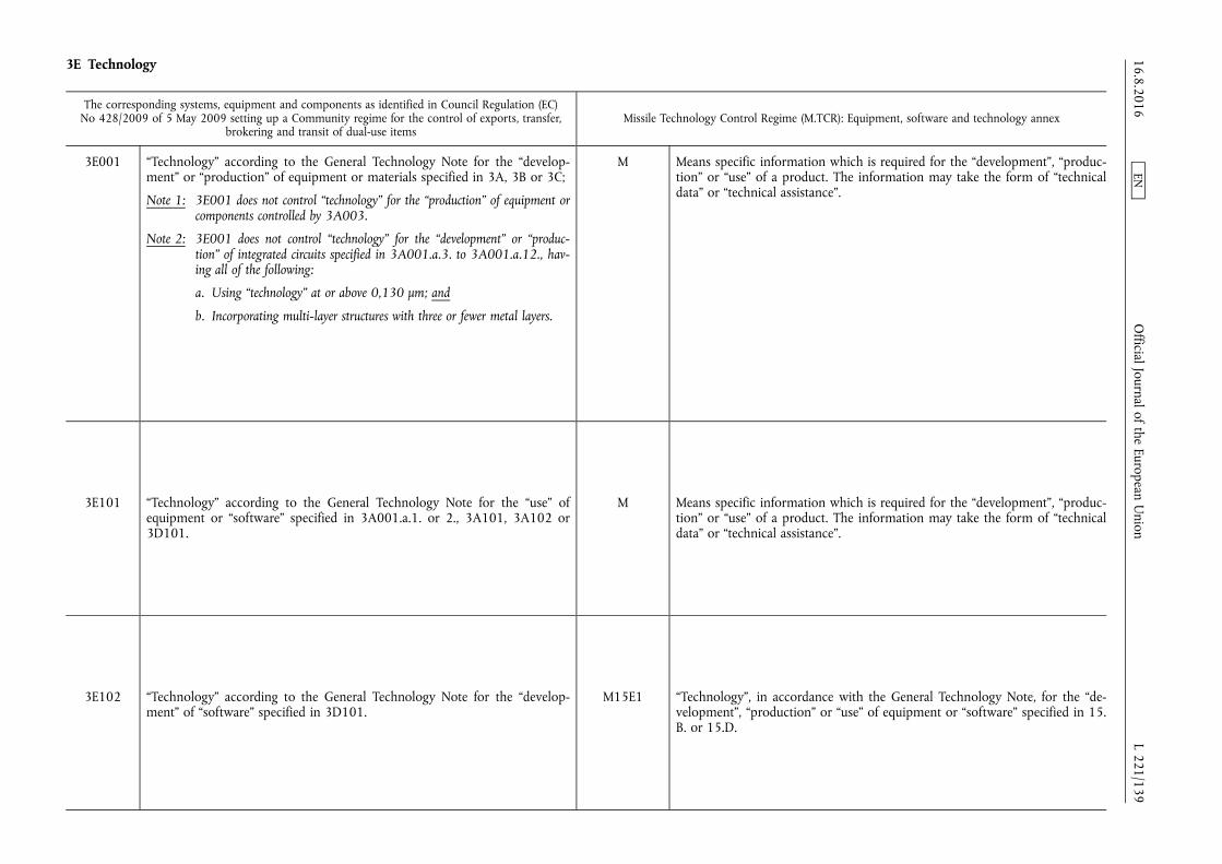
3E Technology
The corresponding systems, equipment and components as identified in Council Regulation (EC) No 428/2009 of 5 May 2009 setting up a Community regime for the control of exports, transfer,
brokering and transit of dual-use items Missile Technology Control Regime (M.TCR): Equipment, software and technology annex
3E001 “Technology” according to the General Technology Note for the “development” or “production” of equipment or materials specified in 3A, 3B or 3C;
Note 1: 3E001 does not control “technology” for the “production” of equipment or components controlled by 3A003.
Note 2: 3E001 does not control “technology” for the “development” or “production” of integrated circuits specified in 3A001.a.3. to 3A001.a.12., having all of the following:
a. Using “technology” at or above 0,130 µm; and
b. Incorporating multi-layer structures with three or fewer metal layers.
M Means specific information which is required for the “development”, “production” or “use” of a product. The information may take the form of “technical data” or “technical assistance”.
3E101 “Technology” according to the General Technology Note for the “use” of equipment or “software” specified in 3A001.a.1. or 2., 3A101, 3A102 or 3D101.
M Means specific information which is required for the “development”, “production” or “use” of a product. The information may take the form of “technical data” or “technical assistance”.
3E102 “Technology” according to the General Technology Note for the “development” of “software” specified in 3D101.
M15E1 “Technology”, in accordance with the General Technology Note, for the “development”, “production” or “use” of equipment or “software” specified in 15. B. or 15.D.
16.8.2016 L 221/139
Official Journal of the European U
nion EN
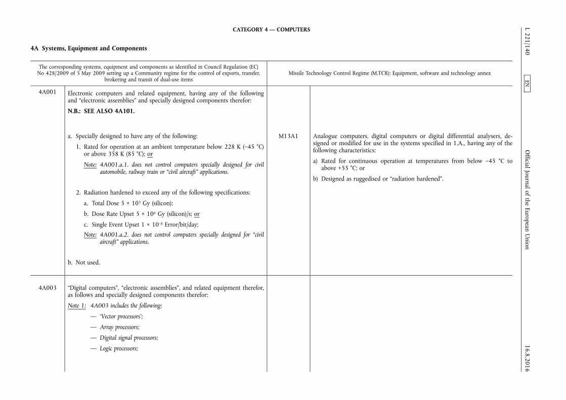
CATEGORY 4 — COMPUTERS
4A Systems, Equipment and Components
The corresponding systems, equipment and components as identified in Council Regulation (EC) No 428/2009 of 5 May 2009 setting up a Community regime for the control of exports, transfer,
brokering and transit of dual-use items Missile Technology Control Regime (M.TCR): Equipment, software and technology annex
4A001 Electronic computers and related equipment, having any of the following and “electronic assemblies” and specially designed components therefor:
N.B.: SEE ALSO 4A101.
a. Specially designed to have any of the following:
1. Rated for operation at an ambient temperature below 228 K (–45 °C) or above 358 K (85 °C); or
Note: 4A001.a.1. does not control computers specially designed for civil automobile, railway train or “civil aircraft” applications.
2. Radiation hardened to exceed any of the following specifications:
a. Total Dose 5 × 10³ Gy (silicon);
b. Dose Rate Upset 5 × 10⁶ Gy (silicon)/s; or
c. Single Event Upset 1 × 10⁻⁸ Error/bit/day;
Note: 4A001.a.2. does not control computers specially designed for “civil aircraft” applications.
b. Not used.
M13A1 Analogue computers, digital computers or digital differential analysers, designed or modified for use in the systems specified in 1.A., having any of the following characteristics:
a) Rated for continuous operation at temperatures from below –45 °C to above +55 °C; or
b) Designed as ruggedised or “radiation hardened”.
4A003 “Digital computers”, “electronic assemblies”, and related equipment therefor, as follows and specially designed components therefor:
Note 1: 4A003 includes the following:
— ‘Vector processors’;
— Array processors;
— Digital signal processors;
— Logic processors;
16.8.2016 L 221/140
Official Journal of the European U
nion EN

— Equipment designed for “image enhancement”;
— Equipment designed for “signal processing”.
Note 2: The control status of the “digital computers” and related equipment described in 4A003 is determined by the control status of other equipment or systems provided:
a. The “digital computers” or related equipment are essential for the operation of the other equipment or systems;
b. The “digital computers” or related equipment are not a “principal element” of the other equipment or systems; and
N.B. 1: The control status of “signal processing” or “image enhancement” equipment specially designed for other equipment with functions limited to those required for the other equipment is determined by the control status of the other equipment even if it exceeds the “principal element” criterion.
N.B. 2: For the control status of “digital computers” or related equipment for telecommunications equipment, see Category 5, Part 1 (Telecommunications).
c. The “technology” for the “digital computers” and related equipment is determined by 4E.
d. Not used
e. Equipment performing analogue-to-digital conversions exceeding the limits specified in 3A001.a.5.;
M14A1b2 Electrical input type analogue-to-digital converter printed circuit boards or modules, having all of the following characteristics:
a) Rated for operation in the temperature range from below –45 °C to above +80 °C; and
b) Incorporating “microcircuits” specified in 14.A.1.b.1.
4A101 Analogue computers, “digital computers” or digital differential analysers, other than those specified in 4A001.a.1., which are ruggedized and designed or modified for use in space launch vehicles specified in 9A004 or sounding rockets specified in 9A104.
M13A1b Designed as ruggedised or “radiation hardened”.
16.8.2016 L 221/141
Official Journal of the European U
nion EN

4A102 “Hybrid computers” specially designed for modelling, simulation or design integration of space launch vehicles specified in 9A004 or sounding rockets specified in 9A104.
Note: This control only applies when the equipment is supplied with “software” specified in 7D103 or 9D103.
M16A1 Specially designed hybrid (combined analogue/digital) computers for modelling, simulation or design integration of systems specified in 1.A. or the subsystems specified in 2.A.
Note: This control only applies when the equipment is supplied with “software” specified in 16.D.1.
4E Technology
The corresponding systems, equipment and components as identified in Council Regulation (EC) No 428/2009 of 5 May 2009 setting up a Community regime for the control of exports, transfer,
brokering and transit of dual-use items Missile Technology Control Regime (M.TCR): Equipment, software and technology annex
4E001 a. “Technology” according to the General Technology Note, for the “development”, “production” or “use” of equipment or “software” specified in 4A or 4D.
b. “Technology”, other than that specified in 4E001.a., specially designed or modified for the “development” or “production” of equipment as follows:
1. “Digital computers” having an “Adjusted Peak Performance” (“APP”) exceeding 1,0 Weighted TeraFLOPS (WT);
2. “Electronic assemblies” specially designed or modified for enhancing performance by aggregation of processors so that the “APP” of the aggregation exceeds the limit in 4E001.b.1.
c. “Technology” for the “development” of “intrusion software”.
M Means specific information which is required for the “development”, “production” or “use” of a product. The information may take the form of “technical data” or “technical assistance”.
16.8.2016 L 221/142
Official Journal of the European U
nion EN
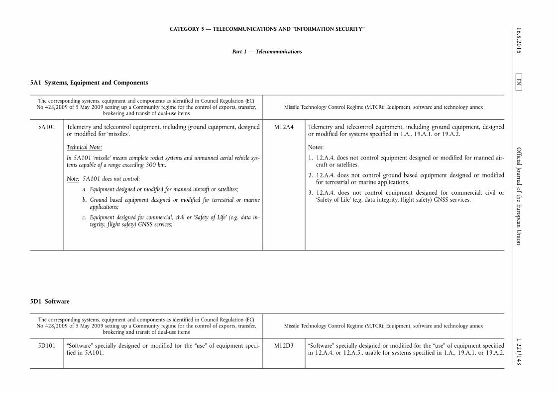
CATEGORY 5 — TELECOMMUNICATIONS AND “INFORMATION SECURITY”
Part 1 — Telecommunications
5A1 Systems, Equipment and Components
The corresponding systems, equipment and components as identified in Council Regulation (EC) No 428/2009 of 5 May 2009 setting up a Community regime for the control of exports, transfer,
brokering and transit of dual-use items Missile Technology Control Regime (M.TCR): Equipment, software and technology annex
5A101 Telemetry and telecontrol equipment, including ground equipment, designed or modified for ‘missiles’.
Technical Note:
In 5A101 ‘missile’ means complete rocket systems and unmanned aerial vehicle systems capable of a range exceeding 300 km.
Note: 5A101 does not control:
a. Equipment designed or modified for manned aircraft or satellites;
b. Ground based equipment designed or modified for terrestrial or marine applications;
c. Equipment designed for commercial, civil or ‘Safety of Life’ (e.g. data integrity, flight safety) GNSS services;
M12A4 Telemetry and telecontrol equipment, including ground equipment, designed or modified for systems specified in 1.A., 19.A.1. or 19.A.2.
Notes:
1. 12.A.4. does not control equipment designed or modified for manned aircraft or satellites.
2. 12.A.4. does not control ground based equipment designed or modified for terrestrial or marine applications.
3. 12.A.4. does not control equipment designed for commercial, civil or ‘Safety of Life’ (e.g. data integrity, flight safety) GNSS services.
5D1 Software
The corresponding systems, equipment and components as identified in Council Regulation (EC) No 428/2009 of 5 May 2009 setting up a Community regime for the control of exports, transfer,
brokering and transit of dual-use items Missile Technology Control Regime (M.TCR): Equipment, software and technology annex
5D101 “Software” specially designed or modified for the “use” of equipment specified in 5A101.
M12D3 “Software” specially designed or modified for the “use” of equipment specified in 12.A.4. or 12.A.5., usable for systems specified in 1.A., 19.A.1. or 19.A.2.
16.8.2016 L 221/143
Official Journal of the European U
nion EN

5E1 Technology
The corresponding systems, equipment and components as identified in Council Regulation (EC) No 428/2009 of 5 May 2009 setting up a Community regime for the control of exports, transfer,
brokering and transit of dual-use items Missile Technology Control Regime (M.TCR): Equipment, software and technology annex
5E101 “Technology” according to the General Technology Note for the “development”, “production” or “use” of equipment specified in 5A101.
M12E1 “Technology”, in accordance with the General Technology Note, for the “development”, “production” or “use” of equipment or “software” specified in 12. A. or 12.D.
CATEGORY 6 — SENSORS AND LASERS
6A Systems, Equipment and Components
The corresponding systems, equipment and components as identified in Council Regulation (EC) No 428/2009 of 5 May 2009 setting up a Community regime for the control of exports, transfer,
brokering and transit of dual-use items Missile Technology Control Regime (M.TCR): Equipment, software and technology annex
6A002 Optical sensors or equipment and components therefor, as follows:
N.B.: SEE ALSO 6A102.
a. Optical detectors as follows:
1. “Space-qualified” solid-state detectors as follows:
Note: For the purpose of 6A002.a.1., solid-state detectors include “focal plane arrays”.
a. “Space-qualified” solid-state detectors having all of the following:
1. A peak response in the wavelength range exceeding 10 nm but not exceeding 300 nm; and
2. A response of less than 0,1 % relative to the peak response at a wavelength exceeding 400 nm;
M18A2 ‘Detectors’ specially designed or modified to protect rocket systems and unmanned aerial vehicles against nuclear effects (e.g. Electromagnetic Pulse (EMP), X-rays, combined blast and thermal effects), and usable for the systems specified in 1.A.
Technical Note:
A ‘detector’ is defined as a mechanical, electrical, optical or chemical device that automatically identifies and records, or registers a stimulus such as an environmental change in pressure or temperature, an electrical or electromagnetic signal or radiation from a radioactive material. This includes devices that sense by one time operation or failure
b. “Space-qualified” solid-state detectors having all of the following:
1. A peak response in the wavelength range exceeding 900 nm but not exceeding 1 200 nm; and
2. A response “time constant” of 95 ns or less;
M11A2 Passive sensors for determining bearings to specific electromagnetic sources (direction finding equipment) or terrain characteristics, designed or modified for use in the systems specified in 1.A. 16.8.2016
L 221/144 O
fficial Journal of the European Union
EN
c. “Space-qualified” solid-state detectors having a peak response in the wavelength range exceeding 1 200 nm but not exceeding 30 000 nm;
d. “Space-qualified” “focal plane arrays” having more than 2 048 elements per array and having a peak response in the wavelength range exceeding 300 nm but not exceeding 900 nm.
6A006 “Magnetometers”, “magnetic gradiometers”, “intrinsic magnetic gradiometers”, underwater electric field sensors, “compensation systems”, and specially designed components therefor, as follows:
N.B.: SEE ALSO 7A103.d.
Note: 6A006 does not control instruments specially designed for fishery applications or biomagnetic measurements for medical diagnostics.
a. “Magnetometers” and subsystems as follows:
1. “Magnetometers” using “superconductive” (SQUID) “technology” and having any of the following:
a. SQUID systems designed for stationary operation, without specially designed subsystems designed to reduce in-motion noise, and having a ‘sensitivity’ equal to or lower (better) than 50 fT (rms) per square root Hz at a frequency of 1 Hz; or
b. SQUID systems having an in-motion-magnetometer ‘sensitivity’ lower (better) than 20 pT (rms) per square root Hz at a frequency of 1 Hz and specially designed to reduce in-motion noise;
2. “Magnetometers” using optically pumped or nuclear precession (proton/Overhauser) “technology” having a ‘sensitivity’ lower (better) than 20 pT (rms) per square root Hz at a frequency of 1 Hz;
3. “Magnetometers” using fluxgate “technology” having a ‘sensitivity’ equal to or lower (better) than 10 pT (rms) per square root Hz at a frequency of 1 Hz;
4. Induction coil “magnetometers” having a ‘sensitivity’ lower (better) than any of the following:
a. 0,05 nT (rms) per square root Hz at frequencies of less than 1 Hz;
M9A8 Three axis magnetic heading sensors having all of the following characteristics, and specially designed components therefor:
a) Internal tilt compensation in pitch (+/– 90 degrees) and having roll (+/– 180 degrees) axes.
b) Capable of providing azimuthal accuracy better (less) than 0,5 degrees rms at latitudes of +/– 80 degrees, referenced to local magnetic field; and
c) Designed or modified to be integrated with flight control and navigation systems.
Note: Flight control and navigation systems in Item 9.A.8. include gyrostabilisers, automatic pilots and inertial navigation systems.
16.8.2016 L 221/145
Official Journal of the European U
nion EN
b. 1 × 10⁻³ nT (rms) per square root Hz at frequencies of 1 Hz or more but not exceeding 10 Hz; or
c. 1 × 10⁻⁴ nT (rms) per square root Hz at frequencies exceeding 10 Hz;
5. Fibre optic “magnetometers” having a ‘sensitivity’ lower (better) than 1 nT (rms) per square root Hz;
b. Underwater electric field sensors having a ‘sensitivity’ lower (better) than 8 nanovolt per metre per square root Hz when measured at 1 Hz;
c. “Magnetic gradiometers” as follows:
1. “Magnetic gradiometers” using multiple “magnetometers” specified in 6A006.a.;
2. Fibre optic “intrinsic magnetic gradiometers” having a magnetic gradient field ‘sensitivity’ lower (better) than 0,3 nT/m rms per square root Hz;
3. “Intrinsic magnetic gradiometers”, using “technology” other than fibre-optic “technology”, having a magnetic gradient field ‘sensitivity’ lower (better) than 0,015 nT/m rms per square root Hz;
d. “Compensation systems” for magnetic or underwater electric field sensors resulting in a performance equal to or better than the specified parameters of 6A006.a., 6A006.b. or 6A006.c.;
6A007 Gravity meters (gravimeters) and gravity gradiometers, as follows:
N.B.: SEE ALSO 6A107.
a. Gravity meters designed or modified for ground use and having a static accuracy of less (better) than 10 µGal;
Note: 6A007.a. does not control ground gravity meters of the quartz element (Worden) type.
b. Gravity meters designed for mobile platforms and having all of the following:
1. A static accuracy of less (better) than 0,7 mGal; and
M12A3 Gravity meters (gravimeters) or gravity gradiometers, designed or modified for airborne or marine use, usable for systems specified in 1.A., as follows, and specially designed components therefor:
a) Gravity meters having all the following:
1. A static or operational accuracy equal to or less (better) than 0,7 milligal (mgal); and
2. A time to steady-state registration of two minutes or less;
b) Gravity gradiometers.
16.8.2016 L 221/146
Official Journal of the European U
nion EN
2. An in-service (operational) accuracy of less (better) than 0,7 mGal having a ‘time-to-steady-state registration’ of less than 2 minutes under any combination of attendant corrective compensations and motional influences;
Technical Note:
For the purposes of 6A007.b., ‘time-to-steady-state registration’ (also referred to as the gravimeter's response time) is the time over which the disturbing effects of platform induced accelerations (high frequency noise) are reduced.
c. Gravity gradiometers.
6A008 Radar systems, equipment and assemblies, having any of the following, and specially designed components therefor:
N.B.: SEE ALSO 6A108.
Note: 6A008 does not control:
— Secondary surveillance radar (SSR);
— Civil Automotive Radar;
— Displays or monitors used for air traffic control (ATC);
— Meteorological (weather) radar;
— Precision approach radar (PAR) equipment conforming to ICAO standards and employing electronically steerable linear (1-dimensional) arrays or mechanically positioned passive antennae.
M11A1 Radar and laser radar systems, including altimeters, designed or modified for use in the systems specified in 1.A.
Technical Note:
Laser radar systems embody specialised transmission, scanning, receiving and signal processing techniques for utilisation of lasers for echo ranging, direction finding and discrimination of targets by location, radial speed and body reflection characteristics.
a. Operating at frequencies from 40 GHz to 230 GHz and having any of the following:
1. An average output power exceeding 100 mW; or
2. Locating accuracy of 1 m or less (better) in range and 0,2 degree or less (better) in azimuth;
b. A tunable bandwidth exceeding ± 6,25 % of the ‘centre operating frequency’;
M12A5b Range instrumentation radars including associated optical/infrared trackers with all of the following capabilities:
1. Angular resolution better than 1,5 mrad;
2. Range of 30 km or greater with a range resolution better than 10 m rms; and
3. Velocity resolution better than 3 m/s.
16.8.2016 L 221/147
Official Journal of the European U
nion EN
Technical Note:
The ‘centre operating frequency’ equals one half of the sum of the highest plus the lowest specified operating frequencies.
c. Capable of operating simultaneously on more than two carrier frequencies;
6A102 Radiation hardened ‘detectors’, other than those specified in 6A002, specially designed modified for protecting against nuclear effects (e.g. electromagnetic pulse (EMP), X-rays, combined blast and thermal effects) and usable for “missiles”, designed or rated to withstand radiation levels which meet or exceed a total irradiation dose of 5 × 10⁵ rads (silicon).
Technical Note:
In 6A102, a ‘detector’ is defined as a mechanical, electrical, optical or chemical device that automatically identifies and records, or registers a stimulus such as an environmental change in pressure or temperature, an electrical or electromagnetic signal or radiation from a radioactive material. This includes devices that sense by one time operation or failure.
M18A2 ‘Detectors’ specially designed or modified to protect rocket systems and unmanned aerial vehicles against nuclear effects (e.g. Electromagnetic Pulse (EMP), X-rays, combined blast and thermal effects), and usable for the systems specified in 1.A.
Technical Note:
A ‘detector’ is defined as a mechanical, electrical, optical or chemical device that automatically identifies and records, or registers a stimulus such as an environmental change in pressure or temperature, an electrical or electromagnetic signal or radiation from a radioactive material. This includes devices that sense by one time operation or failure.
6A107 Gravity meters (gravimeters) and components for gravity meters and gravity gradiometers, as follows:
a. Gravity meters, other than those specified in 6A007.b, designed or modified for airborne or marine use, and having a static or operational accuracy equal to or less (better) than 0,7 milligal (mgal), and having a time- to-steady-state registration of two minutes or less;
b. Specially designed components for gravity meters specified in 6A007.b or 6A107.a. and gravity gradiometers specified in 6A007.c.
M12A3 Gravity meters (gravimeters) or gravity gradiometers, designed or modified for airborne or marine use, usable for systems specified in 1.A., as follows, and specially designed components therefor:
a) Gravity meters having all the following:
1. A static or operational accuracy equal to or less (better) than 0,7 milligal (mgal); and
2. A time to steady-state registration of two minutes or less;
b) Gravity gradiometers.
16.8.2016 L 221/148
Official Journal of the European U
nion EN

6A108 Radar systems and tracking systems, other than those specified in entry 6A008, as follows:
a. Radar and laser radar systems designed or modified for use in space launch vehicles specified in 9A004 or sounding rockets specified in 9A104;
Note: 6A108.a. includes the following:
a. Terrain contour mapping equipment;
b. Imaging sensor equipment;
c. Scene mapping and correlation (both digital and analogue) equipment;
d. Doppler navigation radar equipment.
M11A1 Radar and laser radar systems, including altimeters, designed or modified for use in the systems specified in 1.A.
Technical Note:
Laser radar systems embody specialised transmission, scanning, receiving and signal processing techniques for utilisation of lasers for echo ranging, direction finding and discrimination of targets by location, radial speed and body reflection characteristics.
b. Precision tracking systems, usable for ‘missiles’, as follows:
1. Tracking systems which use a code translator in conjunction with either surface or airborne references or navigation satellite systems to provide real-time measurements of in-flight position and velocity;
2. Range instrumentation radars including associated optical/infrared trackers with all of the following capabilities:
a. Angular resolution better than 1,5 milliradians;
b. Range of 30 km or greater with a range resolution better than 10 m rms;
c. Velocity resolution better than 3 m/s.
Technical Note:
In 6A108.b. ‘missile’ means complete rocket systems and unmanned aerial vehicle systems capable of a range exceeding 300 km.
M12A5 Precision tracking systems, usable for systems specified in 1.A., 19.A.1. or 19.A.2. as follows:
a. Tracking systems which use a code translator installed on the rocket or unmanned aerial vehicle in conjunction with either surface or airborne references or navigation satellite systems to provide real-time measurements of inflight position and velocity;
b. Range instrumentation radars including associated optical/infrared trackers with all of the following capabilities:
1. Angular resolution better than 1,5 mrad;
2. Range of 30 km or greater with a range resolution better than 10 m rms; and
3. Velocity resolution better than 3 m/s.
16.8.2016 L 221/149
Official Journal of the European U
nion EN
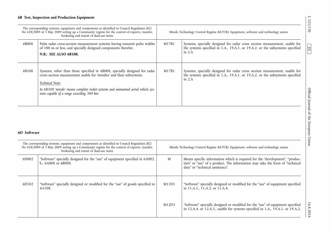
6B Test, Inspection and Production Equipment
The corresponding systems, equipment and components as identified in Council Regulation (EC) No 428/2009 of 5 May 2009 setting up a Community regime for the control of exports, transfer,
brokering and transit of dual-use items Missile Technology Control Regime (M.TCR): Equipment, software and technology annex
6B008 Pulse radar cross-section measurement systems having transmit pulse widths of 100 ns or less, and specially designed components therefor.
N.B.: SEE ALSO 6B108.
M17B1 Systems, specially designed for radar cross section measurement, usable for the systems specified in 1.A., 19.A.1. or 19.A.2. or the subsystems specified in 2.A
6B108 Systems, other than those specified in 6B008, specially designed for radar cross section measurement usable for ‘missiles’ and their subsystems.
Technical Note:
In 6B108 ‘missile’ means complete rocket systems and unmanned aerial vehicle systems capable of a range exceeding 300 km.
M17B1 Systems, specially designed for radar cross section measurement, usable for the systems specified in 1.A., 19.A.1. or 19.A.2. or the subsystems specified in 2.A
6D Software
The corresponding systems, equipment and components as identified in Council Regulation (EC) No 428/2009 of 5 May 2009 setting up a Community regime for the control of exports, transfer,
brokering and transit of dual-use items Missile Technology Control Regime (M.TCR): Equipment, software and technology annex
6D002 “Software” specially designed for the “use” of equipment specified in 6A002. b., 6A008 or 6B008.
M Means specific information which is required for the “development”, “production” or “use” of a product. The information may take the form of “technical data” or “technical assistance”.
6D102 “Software” specially designed or modified for the “use” of goods specified in 6A108.
M11D1 “Software” specially designed or modified for the “use” of equipment specified in 11.A.1., 11.A.2. or 11.A.4.
M12D3 “Software” specially designed or modified for the “use” of equipment specified in 12.A.4. or 12.A.5., usable for systems specified in 1.A., 19.A.1. or 19.A.2.
16.8.2016 L 221/150
Official Journal of the European U
nion EN
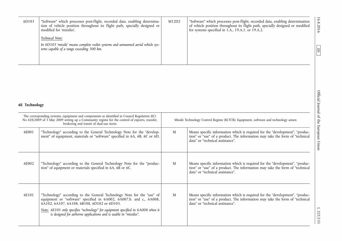
6D103 “Software” which processes post-flight, recorded data, enabling determination of vehicle position throughout its flight path, specially designed or modified for ‘missiles’.
Technical Note:
In 6D103 ‘missile’ means complete rocket systems and unmanned aerial vehicle systems capable of a range exceeding 300 km.
M12D2 “Software” which processes post-flight, recorded data, enabling determination of vehicle position throughout its flight path, specially designed or modified for systems specified in 1.A., 19.A.1. or 19.A.2.
6E Technology
The corresponding systems, equipment and components as identified in Council Regulation (EC) No 428/2009 of 5 May 2009 setting up a Community regime for the control of exports, transfer,
brokering and transit of dual-use items Missile Technology Control Regime (M.TCR): Equipment, software and technology annex
6E001 “Technology” according to the General Technology Note for the “development” of equipment, materials or “software” specified in 6A, 6B, 6C or 6D.
M Means specific information which is required for the “development”, “production” or “use” of a product. The information may take the form of “technical data” or “technical assistance”.
6E002 “Technology” according to the General Technology Note for the “production” of equipment or materials specified in 6A, 6B or 6C.
M Means specific information which is required for the “development”, “production” or “use” of a product. The information may take the form of “technical data” or “technical assistance”.
6E101 “Technology” according to the General Technology Note for the “use” of equipment or “software” specified in 6A002, 6A007.b. and c., 6A008, 6A102, 6A107, 6A108, 6B108, 6D102 or 6D103.
Note: 6E101 only specifies “technology” for equipment specified in 6A008 when it is designed for airborne applications and is usable in “missiles”.
M Means specific information which is required for the “development”, “production” or “use” of a product. The information may take the form of “technical data” or “technical assistance”.
16.8.2016 L 221/151
Official Journal of the European U
nion EN
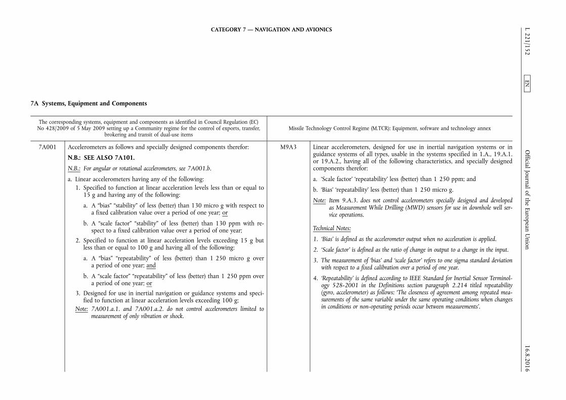
CATEGORY 7 — NAVIGATION AND AVIONICS
7A Systems, Equipment and Components
The corresponding systems, equipment and components as identified in Council Regulation (EC) No 428/2009 of 5 May 2009 setting up a Community regime for the control of exports, transfer,
brokering and transit of dual-use items Missile Technology Control Regime (M.TCR): Equipment, software and technology annex
7A001 Accelerometers as follows and specially designed components therefor:
N.B.: SEE ALSO 7A101.
N.B.: For angular or rotational accelerometers, see 7A001.b.
a. Linear accelerometers having any of the following: 1. Specified to function at linear acceleration levels less than or equal to
15 g and having any of the following:
a. A “bias” “stability” of less (better) than 130 micro g with respect to a fixed calibration value over a period of one year; or
b. A “scale factor” “stability” of less (better) than 130 ppm with respect to a fixed calibration value over a period of one year;
2. Specified to function at linear acceleration levels exceeding 15 g but less than or equal to 100 g and having all of the following:
a. A “bias” “repeatability” of less (better) than 1 250 micro g over a period of one year; and
b. A “scale factor” “repeatability” of less (better) than 1 250 ppm over a period of one year; or
3. Designed for use in inertial navigation or guidance systems and specified to function at linear acceleration levels exceeding 100 g;
Note: 7A001.a.1. and 7A001.a.2. do not control accelerometers limited to measurement of only vibration or shock.
M9A3 Linear accelerometers, designed for use in inertial navigation systems or in guidance systems of all types, usable in the systems specified in 1.A., 19.A.1. or 19.A.2., having all of the following characteristics, and specially designed components therefor:
a. ‘Scale factor’ ‘repeatability’ less (better) than 1 250 ppm; and
b. ‘Bias’ ‘repeatability’ less (better) than 1 250 micro g.
Note: Item 9.A.3. does not control accelerometers specially designed and developed as Measurement While Drilling (MWD) sensors for use in downhole well service operations.
Technical Notes:
1. ‘Bias’ is defined as the accelerometer output when no acceleration is applied.
2. ‘Scale factor’ is defined as the ratio of change in output to a change in the input.
3. The measurement of ‘bias’ and ‘scale factor’ refers to one sigma standard deviation with respect to a fixed calibration over a period of one year.
4. ‘Repeatability’ is defined according to IEEE Standard for Inertial Sensor Terminology 528-2001 in the Definitions section paragraph 2.214 titled repeatability (gyro, accelerometer) as follows: ‘The closeness of agreement among repeated measurements of the same variable under the same operating conditions when changes in conditions or non-operating periods occur between measurements’.
16.8.2016 L 221/152
Official Journal of the European U
nion EN
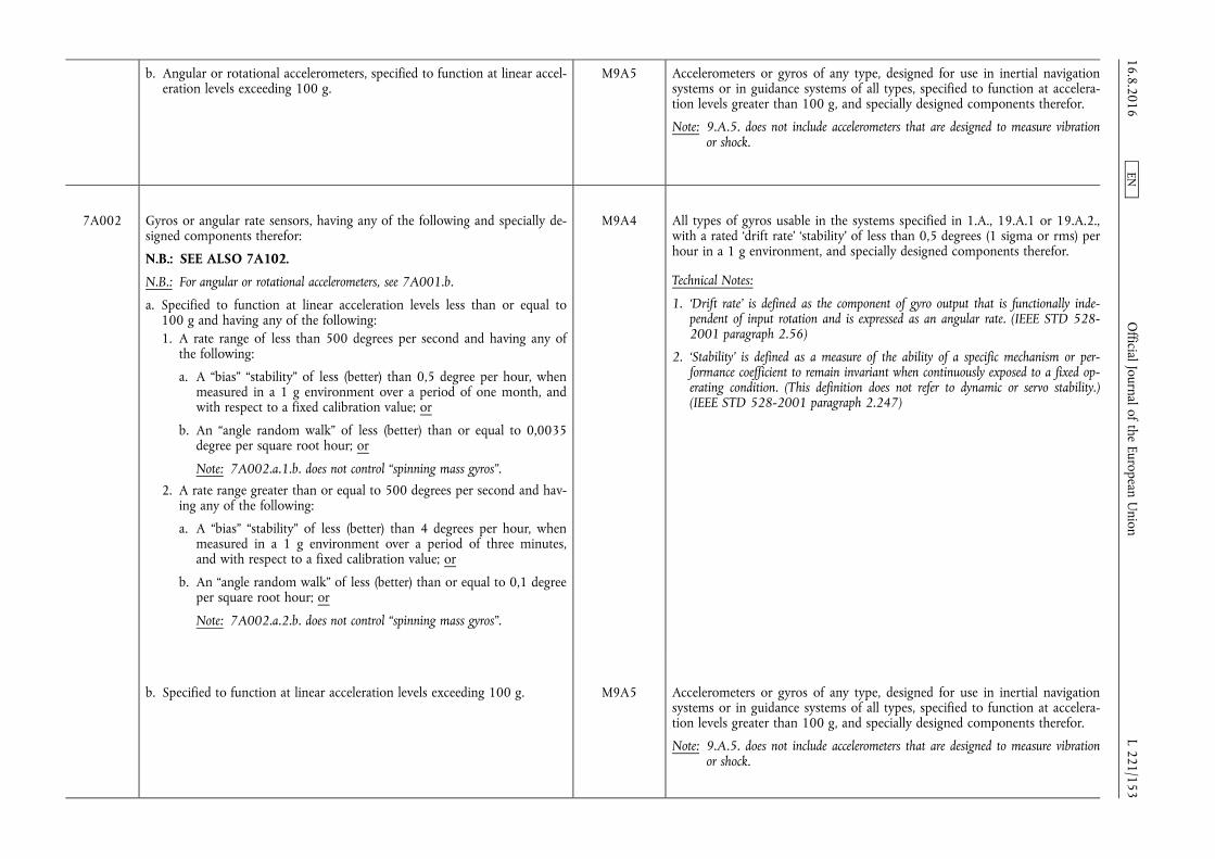
b. Angular or rotational accelerometers, specified to function at linear acceleration levels exceeding 100 g.
M9A5 Accelerometers or gyros of any type, designed for use in inertial navigation systems or in guidance systems of all types, specified to function at acceleration levels greater than 100 g, and specially designed components therefor.
Note: 9.A.5. does not include accelerometers that are designed to measure vibration or shock.
7A002 Gyros or angular rate sensors, having any of the following and specially designed components therefor:
N.B.: SEE ALSO 7A102.
N.B.: For angular or rotational accelerometers, see 7A001.b.
a. Specified to function at linear acceleration levels less than or equal to 100 g and having any of the following: 1. A rate range of less than 500 degrees per second and having any of
the following:
a. A “bias” “stability” of less (better) than 0,5 degree per hour, when measured in a 1 g environment over a period of one month, and with respect to a fixed calibration value; or
b. An “angle random walk” of less (better) than or equal to 0,0035 degree per square root hour; or
Note: 7A002.a.1.b. does not control “spinning mass gyros”.
2. A rate range greater than or equal to 500 degrees per second and having any of the following:
a. A “bias” “stability” of less (better) than 4 degrees per hour, when measured in a 1 g environment over a period of three minutes, and with respect to a fixed calibration value; or
b. An “angle random walk” of less (better) than or equal to 0,1 degree per square root hour; or
Note: 7A002.a.2.b. does not control “spinning mass gyros”.
M9A4 All types of gyros usable in the systems specified in 1.A., 19.A.1 or 19.A.2., with a rated ‘drift rate’ ‘stability’ of less than 0,5 degrees (1 sigma or rms) per hour in a 1 g environment, and specially designed components therefor.
Technical Notes:
1. ‘Drift rate’ is defined as the component of gyro output that is functionally independent of input rotation and is expressed as an angular rate. (IEEE STD 528- 2001 paragraph 2.56)
2. ‘Stability’ is defined as a measure of the ability of a specific mechanism or performance coefficient to remain invariant when continuously exposed to a fixed operating condition. (This definition does not refer to dynamic or servo stability.) (IEEE STD 528-2001 paragraph 2.247)
b. Specified to function at linear acceleration levels exceeding 100 g. M9A5 Accelerometers or gyros of any type, designed for use in inertial navigation systems or in guidance systems of all types, specified to function at acceleration levels greater than 100 g, and specially designed components therefor.
Note: 9.A.5. does not include accelerometers that are designed to measure vibration or shock.
16.8.2016 L 221/153
Official Journal of the European U
nion EN
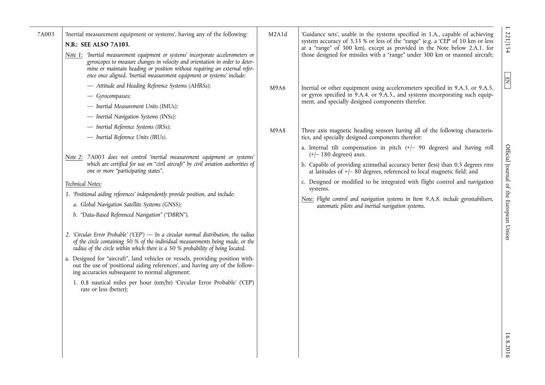
7A003 ‘Inertial measurement equipment or systems’, having any of the following:
N.B.: SEE ALSO 7A103.
Note 1: ‘Inertial measurement equipment or systems’ incorporate accelerometers or gyroscopes to measure changes in velocity and orientation in order to determine or maintain heading or position without requiring an external reference once aligned. ‘Inertial measurement equipment or systems’ include:
— Attitude and Heading Reference Systems (AHRSs);
— Gyrocompasses;
— Inertial Measurement Units (IMUs);
— Inertial Navigation Systems (INSs);
— Inertial Reference Systems (IRSs);
— Inertial Reference Units (IRUs).
Note 2: 7A003 does not control ‘inertial measurement equipment or systems’ which are certified for use on “civil aircraft” by civil aviation authorities of one or more “participating states”.
Technical Notes:
1. ‘Positional aiding references’ independently provide position, and include:
a. Global Navigation Satellite Systems (GNSS);
b. “Data-Based Referenced Navigation” (“DBRN”).
2. ‘Circular Error Probable’ (‘CEP’) — In a circular normal distribution, the radius of the circle containing 50 % of the individual measurements being made, or the radius of the circle within which there is a 50 % probability of being located.
a. Designed for “aircraft”, land vehicles or vessels, providing position without the use of ‘positional aiding references’, and having any of the following accuracies subsequent to normal alignment:
1. 0,8 nautical miles per hour (nm/hr) ‘Circular Error Probable’ (‘CEP’) rate or less (better);
M2A1d ‘Guidance sets’, usable in the systems specified in 1.A., capable of achieving system accuracy of 3,33 % or less of the “range” (e.g. a ‘CEP’ of 10 km or less at a “range” of 300 km), except as provided in the Note below 2.A.1. for those designed for missiles with a “range” under 300 km or manned aircraft;
M9A6 Inertial or other equipment using accelerometers specified in 9.A.3. or 9.A.5. or gyros specified in 9.A.4. or 9.A.5., and systems incorporating such equipment, and specially designed components therefor.
M9A8 Three axis magnetic heading sensors having all of the following characteristics, and specially designed components therefor:
a. Internal tilt compensation in pitch (+/– 90 degrees) and having roll (+/– 180 degrees) axes.
b. Capable of providing azimuthal accuracy better (less) than 0,5 degrees rms at latitudes of +/– 80 degrees, referenced to local magnetic field; and
c. Designed or modified to be integrated with flight control and navigation systems.
Note: Flight control and navigation systems in Item 9.A.8. include gyrostabilisers, automatic pilots and inertial navigation systems.
16.8.2016 L 221/154
Official Journal of the European U
nion EN

2. 0,5 % distanced travelled ‘CEP’ or less (better); or
3. Total drift of 1 nautical mile ‘CEP’ or less (better) in a 24 hr period;
Technical Note:
The performance parameters in 7A003.a.1., 7A003.a.2. and 7A003.a.3. typically apply to ‘inertial measurement equipment or systems’ designed for “aircraft”, vehicles and vessels, respectively. These parameters result from the utilisation of specialised non-positional aiding references (e.g., altimeter, odometer, velocity log). As a consequence, the specified performance values cannot be readily converted between these parameters. Equipment designed for multiple platforms are evaluated against each applicable entry 7A003.a.1., 7A003.a.2., or 7A003. a.3.
b. Designed for “aircraft”, land vehicles or vessels, with an embedded ‘positional aiding reference’ and providing position after loss of all ‘positional aiding references’ for a period of up to 4 minutes, having an accuracy of less (better) than 10 meters ‘CEP’;
Technical Note:
7A003.b. refers to systems in which ‘inertial measurement equipment or systems’ and other independent ‘positional aiding references’ are built into a single unit (i. e., embedded) in order to achieve improved performance.
c. Designed for “aircraft”, land vehicles or vessels, providing heading or True North determination and having any of the following:
1. A maximum operating angular rate less (lower) than 500 deg/s and a heading accuracy without the use of ‘positional aiding references’ equal to or less (better) than 0,07 deg sec(Lat) (equivalent to 6 arc minutes rms at 45 degrees latitude); or
2. A maximum operating angular rate equal to or greater (higher) than 500 deg/s and a heading accuracy without the use of ‘positional aiding references’ equal to or less (better) than 0,2 deg sec(Lat) (equivalent to 17 arc minutes rms at 45 degrees latitude); or
16.8.2016 L 221/155
Official Journal of the European U
nion EN

d. Providing acceleration measurements or angular rate measurements, in more than one dimension, and having any of the following:
1. Performance specified by 7A001 or 7A002 along any axis, without the use of any aiding references; or
2. Being “space-qualified” and providing angular rate measurements having an “angle random walk” along any axis of less (better) than or equal to 0,1 degree per square root hour.
Note: 7A003.d.2. does not control ‘inertial measurement equipment or systems’ that contain “spinning mass gyros” as the only type of gyro.
7A004 ‘Star trackers’ and components therefor, as follows:
N.B.: SEE ALSO 7A104.
a. ‘Star trackers’ with a specified azimuth accuracy of equal to or less (better) than 20 seconds of arc throughout the specified lifetime of the equipment;
b. Components specially designed for equipment specified in 7A004.a. as follows:
1. Optical heads or baffles;
2. Data processing units.
Technical Note:
‘Star trackers’ are also referred to as stellar attitude sensors or gyro-astro compasses.
M9A2 Gyro-astro compasses and other devices which derive position or orientation by means of automatically tracking celestial bodies or satellites, and specially designed components therefor.
7A005 Global Navigation Satellite Systems (GNSS) receiving equipment having any of the following and specially designed components therefor:
N.B.: SEE ALSO 7A105.
N.B.: For equipment specially designed for military use, see Military Goods Controls.
M11A3 Receiving equipment for Global Navigation Satellite Systems (GNSS; e.g. GPS, GLONASS or Galileo), having any of the following characteristics, and specially designed components therefor:
a. Designed or modified for use in systems specified in 1.A.; or
b. Designed or modified for airborne applications and having any of the following:
16.8.2016 L 221/156
Official Journal of the European U
nion EN
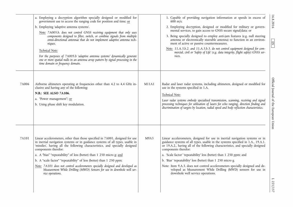
a. Employing a decryption algorithm specially designed or modified for government use to access the ranging code for position and time; or
b. Employing ‘adaptive antenna systems’.
Note: 7A005.b. does not control GNSS receiving equipment that only uses components designed to filter, switch, or combine signals from multiple omni-directional antennae that do not implement adaptive antenna techniques.
Technical Note:
For the purposes of 7A005.b ‘adaptive antenna systems’ dynamically generate one or more spatial nulls in an antenna array pattern by signal processing in the time domain or frequency domain.
1. Capable of providing navigation information at speeds in excess of 600 m/s;
2. Employing decryption, designed or modified for military or governmental services, to gain access to GNSS secure signal/data; or
3. Being specially designed to employ anti-jam features (e.g. null steering antenna or electronically steerable antenna) to function in an environment of active or passive countermeasures.
Note: 11.A.3.b.2. and 11.A.3.b.3. do not control equipment designed for commercial, civil or ‘Safety of Life’ (e.g. data integrity, flight safety) GNSS services.
7A006 Airborne altimeters operating at frequencies other than 4,2 to 4,4 GHz inclusive and having any of the following:
N.B.: SEE ALSO 7A106.
a. “Power management”; or
b. Using phase shift key modulation.
M11A1 Radar and laser radar systems, including altimeters, designed or modified for use in the systems specified in 1.A.
Technical Note:
Laser radar systems embody specialised transmission, scanning, receiving and signal processing techniques for utilisation of lasers for echo ranging, direction finding and discrimination of targets by location, radial speed and body reflection characteristics.
7A101 Linear accelerometers, other than those specified in 7A001, designed for use in inertial navigation systems or in guidance systems of all types, usable in ‘missiles’, having all the following characteristics, and specially designed components therefor:
a. A “bias” “repeatability” of less (better) than 1 250 micro g; and
b. A “scale factor” “repeatability” of less (better) than 1 250 ppm;
Note: 7A101 does not control accelerometers specially designed and developed as Measurement While Drilling (MWD) Sensors for use in downhole well service operations.
M9A3 Linear accelerometers, designed for use in inertial navigation systems or in guidance systems of all types, usable in the systems specified in 1.A., 19.A.1. or 19.A.2., having all of the following characteristics, and specially designed components therefor:
a. ‘Scale factor’ ‘repeatability’ less (better) than 1 250 ppm; and
b. ‘Bias’ ‘repeatability’ less (better) than 1 250 micro g.
Note: Item 9.A.3. does not control accelerometers specially designed and developed as Measurement While Drilling (MWD) sensors for use in downhole well service operations.
16.8.2016 L 221/157
Official Journal of the European U
nion EN

Technical Notes:
1. In 7A101 ‘missile’ means complete rocket systems and unmanned aerial vehicle systems capable of a range exceeding 300 km;
2. In 7A101 the measurement of “bias” and “scale factor” refers to a one sigma standard deviation with respect to a fixed calibration over a period of one year;
Technical Notes:
1. ‘Bias’ is defined as the accelerometer output when no acceleration is applied.
2. ‘Scale factor’ is defined as the ratio of change in output to a change in the input.
3. The measurement of ‘bias’ and ‘scale factor’ refers to one sigma standard deviation with respect to a fixed calibration over a period of one year.
4. ‘Repeatability’ is defined according to IEEE Standard for Inertial Sensor Terminology 528-2001 in the Definitions section paragraph 2.214 titled repeatability (gyro, accelerometer) as follows: ‘The closeness of agreement among repeated measurements of the same variable under the same operating conditions when changes in conditions or non-operating periods occur between measurements’.
7A102 All types of gyros, other than those specified in 7A002, usable in ‘missiles’, with a rated “drift rate” ‘stability’ of less than 0,5° (1 sigma or rms) per hour in a 1 g environment and specially designed components therefor.
Technical Notes:
1. In 7A102 ‘missile’ means complete rocket systems and unmanned aerial vehicle systems capable of a range exceeding 300 km.
2. In 7A102 ‘stability’ is defined as a measure of the ability of a specific mechanism or performance coefficient to remain invariant when continuously exposed to a fixed operating condition (IEEE STD 528-2001 paragraph 2.247).
M9A4 All types of gyros usable in the systems specified in 1.A., 19.A.1 or 19.A.2., with a rated ‘drift rate’ ‘stability’ of less than 0,5 degrees (1 sigma or rms) per hour in a 1 g environment, and specially designed components therefor.
Technical Notes:
1. ‘Drift rate’ is defined as the component of gyro output that is functionally independent of input rotation and is expressed as an angular rate. (IEEE STD 528- 2001 paragraph 2.56)
2. ‘Stability’ is defined as a measure of the ability of a specific mechanism or performance coefficient to remain invariant when continuously exposed to a fixed operating condition. (This definition does not refer to dynamic or servo stability.) (IEEE STD 528-2001 paragraph 2.247)
7A103 Instrumentation, navigation equipment and systems, other than those specified in 7A003, as follows; and specially designed components therefor:
a. Inertial or other equipment, using accelerometers or gyros as follows, and systems incorporating such equipment:
1. Accelerometers specified in 7A001.a.3., 7A001.b. or 7A101 or gyros specified in 7A002 or 7A102; or
M9A6 Inertial or other equipment using accelerometers specified in 9.A.3. or 9.A.5. or gyros specified in 9.A.4. or 9.A.5., and systems incorporating such equipment, and specially designed components therefor.
16.8.2016 L 221/158
Official Journal of the European U
nion EN
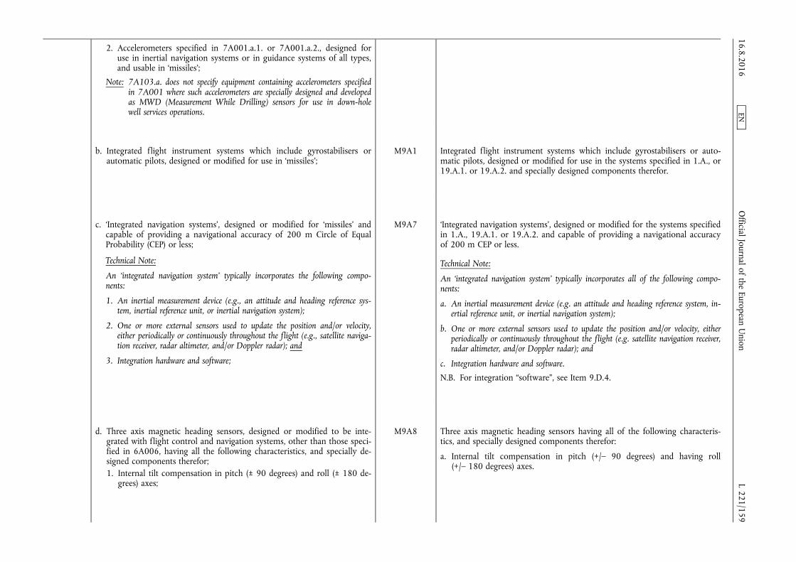
2. Accelerometers specified in 7A001.a.1. or 7A001.a.2., designed for use in inertial navigation systems or in guidance systems of all types, and usable in ‘missiles’;
Note: 7A103.a. does not specify equipment containing accelerometers specified in 7A001 where such accelerometers are specially designed and developed as MWD (Measurement While Drilling) sensors for use in down-hole well services operations.
b. Integrated flight instrument systems which include gyrostabilisers or automatic pilots, designed or modified for use in ‘missiles’;
M9A1 Integrated flight instrument systems which include gyrostabilisers or automatic pilots, designed or modified for use in the systems specified in 1.A., or 19.A.1. or 19.A.2. and specially designed components therefor.
c. ‘Integrated navigation systems’, designed or modified for ‘missiles’ and capable of providing a navigational accuracy of 200 m Circle of Equal Probability (CEP) or less;
Technical Note:
An ‘integrated navigation system’ typically incorporates the following components:
1. An inertial measurement device (e.g., an attitude and heading reference system, inertial reference unit, or inertial navigation system);
2. One or more external sensors used to update the position and/or velocity, either periodically or continuously throughout the flight (e.g., satellite navigation receiver, radar altimeter, and/or Doppler radar); and
3. Integration hardware and software;
M9A7 ‘Integrated navigation systems’, designed or modified for the systems specified in 1.A., 19.A.1. or 19.A.2. and capable of providing a navigational accuracy of 200 m CEP or less.
Technical Note:
An ‘integrated navigation system’ typically incorporates all of the following components:
a. An inertial measurement device (e.g. an attitude and heading reference system, inertial reference unit, or inertial navigation system);
b. One or more external sensors used to update the position and/or velocity, either periodically or continuously throughout the flight (e.g. satellite navigation receiver, radar altimeter, and/or Doppler radar); and
c. Integration hardware and software.
N.B. For integration “software”, see Item 9.D.4.
d. Three axis magnetic heading sensors, designed or modified to be integrated with flight control and navigation systems, other than those specified in 6A006, having all the following characteristics, and specially designed components therefor; 1. Internal tilt compensation in pitch (± 90 degrees) and roll (± 180 de
grees) axes;
M9A8 Three axis magnetic heading sensors having all of the following characteristics, and specially designed components therefor:
a. Internal tilt compensation in pitch (+/– 90 degrees) and having roll (+/– 180 degrees) axes.
16.8.2016 L 221/159
Official Journal of the European U
nion EN

2. Capable of providing azimuthal accuracy better (less) than 0,5 degrees rms at latitude of ± 80 degrees, reference to local magnetic field.
Note: Flight control and navigation systems in 7A103.d. include gyrostabilizers, automatic pilots and inertial navigation systems.
Technical Note:
In 7A103 ‘missile’ means complete rocket systems and unmanned aerial vehicle systems capable of a range exceeding 300 km.
b. Capable of providing azimuthal accuracy better (less) than 0,5 degrees rms at latitudes of +/– 80 degrees, referenced to local magnetic field; and
c. Designed or modified to be integrated with flight control and navigation systems.
Note: Flight control and navigation systems in Item 9.A.8. include gyrostabilisers, automatic pilots and inertial navigation systems.
7A104 Gyro-astro compasses and other devices, other than those specified in 7A004, which derive position or orientation by means of automatically tracking celestial bodies or satellites and specially designed components therefor.
M9A2 Gyro-astro compasses and other devices which derive position or orientation by means of automatically tracking celestial bodies or satellites, and specially designed components therefor.
7A105 Receiving equipment for Global Navigation Satellite Systems (GNSS; e.g. GPS, GLONASS, or Galileo), other than those specified in 7A005, having any of the following characteristics, and specially designed components therefor:
a. Designed or modified for use in space launch vehicles specified in 9A004, sounding rockets specified in 9A104 or unmanned aerial vehicles specified in 9A012 or 9A112.a.; or
b. Designed or modified for airborne applications and having any of the following:
1. Capable of providing navigation information at speeds in excess of 600 m/s;
2. Employing decryption, designed or modified for military or governmental services, to gain access to GNSS secured signal/data; or
3. Being specially designed to employ anti-jam features (e.g. null steering antenna or electronically steerable antenna) to function in an environment of active or passive countermeasures.
Note: 7A105.b.2. and 7A105.b.3. do not control equipment designed for commercial, civil or ‘Safety of Life’ (e.g., data integrity, flight safety) GNSS services.
M11A3 Receiving equipment for Global Navigation Satellite Systems (GNSS; e.g. GPS, GLONASS or Galileo), having any of the following characteristics, and specially designed components therefor:
a. Designed or modified for use in systems specified in 1.A.; or
b. Designed or modified for airborne applications and having any of the following:
1. Capable of providing navigation information at speeds in excess of 600 m/s;
2. Employing decryption, designed or modified for military or governmental services, to gain access to GNSS secure signal/data; or
3. Being specially designed to employ anti-jam features (e.g. null steering antenna or electronically steerable antenna) to function in an environment of active or passive countermeasures.
Note: 11.A.3.b.2. and 11.A.3.b.3. do not control equipment designed for commercial, civil or ‘Safety of Life’ (e.g. data integrity, flight safety) GNSS services.
16.8.2016 L 221/160
Official Journal of the European U
nion EN
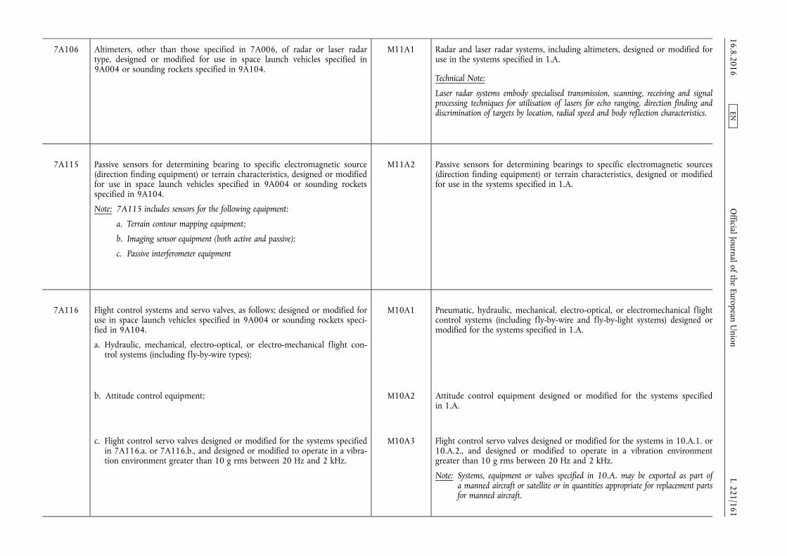
7A106 Altimeters, other than those specified in 7A006, of radar or laser radar type, designed or modified for use in space launch vehicles specified in 9A004 or sounding rockets specified in 9A104.
M11A1 Radar and laser radar systems, including altimeters, designed or modified for use in the systems specified in 1.A.
Technical Note:
Laser radar systems embody specialised transmission, scanning, receiving and signal processing techniques for utilisation of lasers for echo ranging, direction finding and discrimination of targets by location, radial speed and body reflection characteristics.
7A115 Passive sensors for determining bearing to specific electromagnetic source (direction finding equipment) or terrain characteristics, designed or modified for use in space launch vehicles specified in 9A004 or sounding rockets specified in 9A104.
Note: 7A115 includes sensors for the following equipment:
a. Terrain contour mapping equipment;
b. Imaging sensor equipment (both active and passive);
c. Passive interferometer equipment
M11A2 Passive sensors for determining bearings to specific electromagnetic sources (direction finding equipment) or terrain characteristics, designed or modified for use in the systems specified in 1.A.
7A116 Flight control systems and servo valves, as follows; designed or modified for use in space launch vehicles specified in 9A004 or sounding rockets specified in 9A104.
a. Hydraulic, mechanical, electro-optical, or electro-mechanical flight control systems (including fly-by-wire types);
M10A1 Pneumatic, hydraulic, mechanical, electro-optical, or electromechanical flight control systems (including fly-by-wire and fly-by-light systems) designed or modified for the systems specified in 1.A.
b. Attitude control equipment; M10A2 Attitude control equipment designed or modified for the systems specified in 1.A.
c. Flight control servo valves designed or modified for the systems specified in 7A116.a. or 7A116.b., and designed or modified to operate in a vibration environment greater than 10 g rms between 20 Hz and 2 kHz.
M10A3 Flight control servo valves designed or modified for the systems in 10.A.1. or 10.A.2., and designed or modified to operate in a vibration environment greater than 10 g rms between 20 Hz and 2 kHz.
Note: Systems, equipment or valves specified in 10.A. may be exported as part of a manned aircraft or satellite or in quantities appropriate for replacement parts for manned aircraft.
16.8.2016 L 221/161
Official Journal of the European U
nion EN
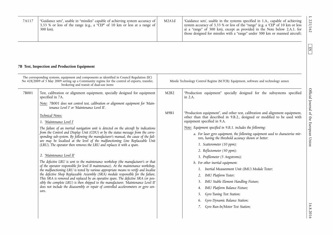
7A117 “Guidance sets”, usable in “missiles” capable of achieving system accuracy of 3,33 % or less of the range (e.g., a “CEP” of 10 km or less at a range of 300 km).
M2A1d ‘Guidance sets’, usable in the systems specified in 1.A., capable of achieving system accuracy of 3,33 % or less of the “range” (e.g. a ‘CEP’ of 10 km or less at a “range” of 300 km), except as provided in the Note below 2.A.1. for those designed for missiles with a “range” under 300 km or manned aircraft;
7B Test, Inspection and Production Equipment
The corresponding systems, equipment and components as identified in Council Regulation (EC) No 428/2009 of 5 May 2009 setting up a Community regime for the control of exports, transfer,
brokering and transit of dual-use items Missile Technology Control Regime (M.TCR): Equipment, software and technology annex
7B001 Test, calibration or alignment equipment, specially designed for equipment specified in 7A.
Note: 7B001 does not control test, calibration or alignment equipment for ‘Maintenance Level I’ or ‘Maintenance Level II’.
Technical Notes:
1. ‘Maintenance Level I’
The failure of an inertial navigation unit is detected on the aircraft by indications from the Control and Display Unit (CDU) or by the status message from the corresponding sub-system. By following the manufacturer's manual, the cause of the failure may be localised at the level of the malfunctioning Line Replaceable Unit (LRU). The operator then removes the LRU and replaces it with a spare.
2. ‘Maintenance Level II’
The defective LRU is sent to the maintenance workshop (the manufacturer's or that of the operator responsible for level II maintenance). At the maintenance workshop, the malfunctioning LRU is tested by various appropriate means to verify and localise the defective Shop Replaceable Assembly (SRA) module responsible for the failure. This SRA is removed and replaced by an operative spare. The defective SRA (or possibly the complete LRU) is then shipped to the manufacturer. ‘Maintenance Level II’ does not include the disassembly or repair of controlled accelerometers or gyro sensors.
M2B2 “Production equipment” specially designed for the subsystems specified in 2.A.
M9B1 “Production equipment”, and other test, calibration and alignment equipment, other than that described in 9.B.2., designed or modified to be used with equipment specified in 9.A.
Note: Equipment specified in 9.B.1. includes the following:
a. For laser gyro equipment, the following equipment used to characterise mirrors, having the threshold accuracy shown or better:
1. Scatterometer (10 ppm);
2. Reflectometer (50 ppm);
3. Profilometer (5 Angstroms);
b. For other inertial equipment:
1. Inertial Measurement Unit (IMU) Module Tester;
2. IMU Platform Tester;
3. IMU Stable Element Handling Fixture;
4. IMU Platform Balance Fixture;
5. Gyro Tuning Test Station;
6. Gyro Dynamic Balance Station;
7. Gyro Run-In/Motor Test Station;
16.8.2016 L 221/162
Official Journal of the European U
nion EN

8. Gyro Evacuation and Filling Station;
9. Centrifuge Fixture for Gyro Bearings;
10. Accelerometer Axis Align Station;
11. Accelerometer Test Station;
12. Fibre Optic Gyro Coil Winding Machines
M10B1 Test, calibration, and alignment equipment specially designed for equipment specified in 10.A.
7B002 Equipment specially designed to characterize mirrors for ring “laser” gyros, as follows:
N.B.: SEE ALSO 7B102.
a. Scatterometers having a measurement accuracy of 10 ppm or less (better);
b. Profilometers having a measurement accuracy of 0,5 nm (5 angstrom) or less (better).
M9B1 “Production equipment”, and other test, calibration and alignment equipment, other than that described in 9.B.2., designed or modified to be used with equipment specified in 9.A.
Note: Equipment specified in 9.B.1. includes the following:
a. For laser gyro equipment, the following equipment used to characterise mirrors, having the threshold accuracy shown or better:
1. Scatterometer (10 ppm);
2. Reflectometer (50 ppm);
3. Profilometer (5 Angstroms);
b. For other inertial equipment:
1. Inertial Measurement Unit (IMU) Module Tester;
2. IMU Platform Tester;
3. IMU Stable Element Handling Fixture;
4. IMU Platform Balance Fixture;
5. Gyro Tuning Test Station;
6. Gyro Dynamic Balance Station;
7. Gyro Run-In/Motor Test Station;
8. Gyro Evacuation and Filling Station;
16.8.2016 L 221/163
Official Journal of the European U
nion EN
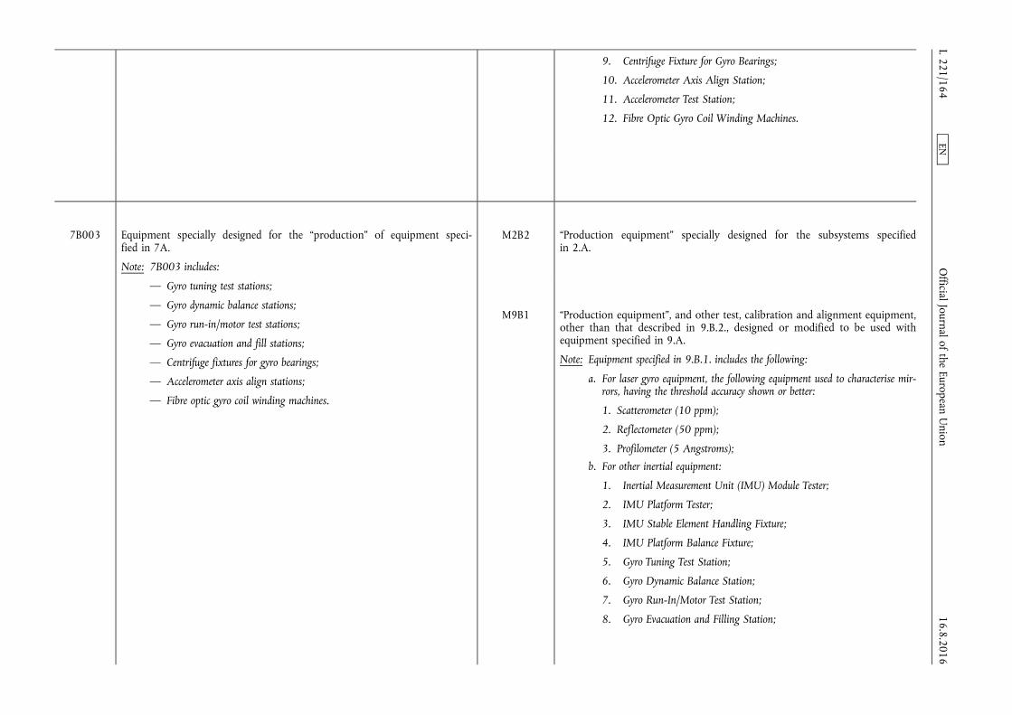
9. Centrifuge Fixture for Gyro Bearings;
10. Accelerometer Axis Align Station;
11. Accelerometer Test Station;
12. Fibre Optic Gyro Coil Winding Machines.
7B003 Equipment specially designed for the “production” of equipment specified in 7A.
Note: 7B003 includes:
— Gyro tuning test stations;
— Gyro dynamic balance stations;
— Gyro run-in/motor test stations;
— Gyro evacuation and fill stations;
— Centrifuge fixtures for gyro bearings;
— Accelerometer axis align stations;
— Fibre optic gyro coil winding machines.
M2B2 “Production equipment” specially designed for the subsystems specified in 2.A.
M9B1 “Production equipment”, and other test, calibration and alignment equipment, other than that described in 9.B.2., designed or modified to be used with equipment specified in 9.A.
Note: Equipment specified in 9.B.1. includes the following:
a. For laser gyro equipment, the following equipment used to characterise mirrors, having the threshold accuracy shown or better:
1. Scatterometer (10 ppm);
2. Reflectometer (50 ppm);
3. Profilometer (5 Angstroms);
b. For other inertial equipment:
1. Inertial Measurement Unit (IMU) Module Tester;
2. IMU Platform Tester;
3. IMU Stable Element Handling Fixture;
4. IMU Platform Balance Fixture;
5. Gyro Tuning Test Station;
6. Gyro Dynamic Balance Station;
7. Gyro Run-In/Motor Test Station;
8. Gyro Evacuation and Filling Station; 16.8.2016 L 221/164
Official Journal of the European U
nion EN

9. Centrifuge Fixture for Gyro Bearings;
10. Accelerometer Axis Align Station;
11. Accelerometer Test Station;
12. Fibre Optic Gyro Coil Winding Machines.
7B102 Reflectometers specially designed to characterise mirrors, for “laser” gyros, having a measurement accuracy of 50 ppm or less (better).
M9B1 “Production equipment”, and other test, calibration and alignment equipment, other than that described in 9.B.2., designed or modified to be used with equipment specified in 9.A.
Note: Equipment specified in 9.B.1. includes the following:
a. For laser gyro equipment, the following equipment used to characterise mirrors, having the threshold accuracy shown or better:
1. Scatterometer (10 ppm);
2. Reflectometer (50 ppm);
3. Profilometer (5 Angstroms);
b. For other inertial equipment:
1. Inertial Measurement Unit (IMU) Module Tester;
2. IMU Platform Tester;
3. IMU Stable Element Handling Fixture;
4. IMU Platform Balance Fixture;
5. Gyro Tuning Test Station;
6. Gyro Dynamic Balance Station;
7. Gyro Run-In/Motor Test Station;
8. Gyro Evacuation and Filling Station;
9. Centrifuge Fixture for Gyro Bearings;
10. Accelerometer Axis Align Station;
11. Accelerometer Test Station;
12. Fibre Optic Gyro Coil Winding Machines.
16.8.2016 L 221/165
Official Journal of the European U
nion EN
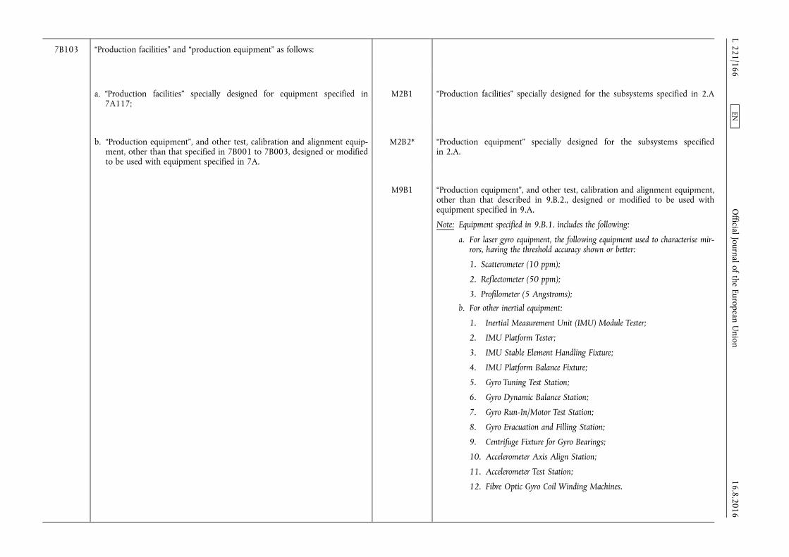
7B103 “Production facilities” and “production equipment” as follows:
a. “Production facilities” specially designed for equipment specified in 7A117;
M2B1 “Production facilities” specially designed for the subsystems specified in 2.A
b. “Production equipment”, and other test, calibration and alignment equipment, other than that specified in 7B001 to 7B003, designed or modified to be used with equipment specified in 7A.
M2B2* “Production equipment” specially designed for the subsystems specified in 2.A.
M9B1 “Production equipment”, and other test, calibration and alignment equipment, other than that described in 9.B.2., designed or modified to be used with equipment specified in 9.A.
Note: Equipment specified in 9.B.1. includes the following:
a. For laser gyro equipment, the following equipment used to characterise mirrors, having the threshold accuracy shown or better:
1. Scatterometer (10 ppm);
2. Reflectometer (50 ppm);
3. Profilometer (5 Angstroms);
b. For other inertial equipment:
1. Inertial Measurement Unit (IMU) Module Tester;
2. IMU Platform Tester;
3. IMU Stable Element Handling Fixture;
4. IMU Platform Balance Fixture;
5. Gyro Tuning Test Station;
6. Gyro Dynamic Balance Station;
7. Gyro Run-In/Motor Test Station;
8. Gyro Evacuation and Filling Station;
9. Centrifuge Fixture for Gyro Bearings;
10. Accelerometer Axis Align Station;
11. Accelerometer Test Station;
12. Fibre Optic Gyro Coil Winding Machines.
16.8.2016 L 221/166
Official Journal of the European U
nion EN

7D Software
The corresponding systems, equipment and components as identified in Council Regulation (EC) No 428/2009 of 5 May 2009 setting up a Community regime for the control of exports, transfer,
brokering and transit of dual-use items Missile Technology Control Regime (M.TCR): Equipment, software and technology annex
7D002 “Source code” for the operation or maintenance of any inertial navigation equipment, including inertial equipment not specified in 7A003 or 7A004, or Attitude and Heading Reference Systems (‘AHRS’).
Note: 7D002 does not control “source code” for the “use” of gimballed ‘AHRS’.
Technical Note:
‘AHRS’ generally differ from Inertial Navigation Systems (INS) in that an ‘AHRS’ provides attitude and heading information and normally does not provide the acceleration, velocity and position information associated with an INS.
M2D3 “Software”, specially designed or modified for the operation or maintenance of ‘guidance sets’ specified in 2.A.1.d.
Note: 2.D.3. includes “software”, specially designed or modified to enhance the performance of ‘guidance sets’ to achieve or exceed the accuracy specified in 2.A.1.d.
M9D1 “Software” specially designed or modified for the “use” of equipment specified in 9.A. or 9.B.
7D101 “Software” specially designed or modified for the “use” of equipment specified in 7A001 to 7A006, 7A101 to 7A106, 7A115, 7A116.a., 7A116.b., 7B001, 7B002, 7B003, 7B102 or 7B103.
M2D “Software” specially designed or modified for the “use” of “production facilities” specified in 2.B.1.
M9D1 “Software” specially designed or modified for the “use” of equipment specified in 9.A. or 9.B.
M10D1 “Software” specially designed or modified for the “use” of equipment specified in 10.A. or 10.B.
Note: “Software” specified in 10.D.1. may be exported as part of a manned aircraft or satellite or in quantities appropriate for replacement parts for manned aircraft.
M11D1&2 “Software” specially designed or modified for the “use” of equipment specified in 11.A.1., 11.A.2. or 11.A.4.
“Software” specially designed for the “use” of equipment specified in 11.A.3.
16.8.2016 L 221/167
Official Journal of the European U
nion EN

7D102 Integration “software” as follows:
a. Integration “software” for the equipment specified in 7A103.b.;
M9D2 Integration “software” for the equipment specified in 9.A.1.
b. Integration “software” specially designed for the equipment specified in 7A003 or 7A103.a.
M9D3* Integration “software” specially designed for the equipment specified in 9.A.6.
c. Integration “software” designed or modified for the equipment specified in 7A103.c.
Note: A common form of integration “software” employs Kalman filtering.
M9D4 Integration “software”, designed or modified for the ‘integrated navigation systems’ specified in 9.A.7.
Note: A common form of integration “software” employs Kalman filtering.
7D103 “Software” specially designed for modelling or simulation of the “guidance sets” specified in 7A117 or for their design integration with the space launch vehicles specified in 9A004 or sounding rockets specified in 9A104.
Note: “Software” specified in 7D103 remains controlled when combined with specially designed hardware specified in 4A102.
M16D1 “Software” specially designed for modelling, simulation, or design integration of the systems specified in 1.A. or the subsystems specified in 2.A or 20.A.
Technical Note: The modelling includes in particular the aerodynamic and thermodynamic analysis of the systems.
7E Technology
The corresponding systems, equipment and components as identified in Council Regulation (EC) No 428/2009 of 5 May 2009 setting up a Community regime for the control of exports, transfer,
brokering and transit of dual-use items Missile Technology Control Regime (M.TCR): Equipment, software and technology annex
7E001 “Technology” according to the General Technology Note for the “development” of equipment or “software”, specified in 7A, 7B, 7D001, 7D002, 7D003, 7D005 and 7D101 to 7D103.
Note: 7E001 includes key management “technology” exclusively for equipment specified in 7A005.a.
M Means specific information which is required for the “development”, “production” or “use” of a product. The information may take the form of “technical data” or “technical assistance”.
16.8.2016 L 221/168
Official Journal of the European U
nion EN
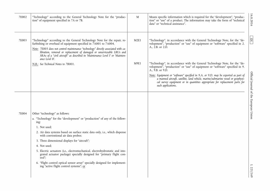
7E002 “Technology” according to the General Technology Note for the “production” of equipment specified in 7A or 7B.
M Means specific information which is required for the “development”, “production” or “use” of a product. The information may take the form of “technical data” or “technical assistance”.
7E003 “Technology” according to the General Technology Note for the repair, refurbishing or overhaul of equipment specified in 7A001 to 7A004.
Note: 7E003 does not control maintenance “technology” directly associated with calibration, removal or replacement of damaged or unserviceable LRUs and SRAs of a “civil aircraft” as described in ‘Maintenance Level I’ or ‘Maintenance Level II’.
N.B.: See Technical Notes to 7B001.
M2E1 “Technology”, in accordance with the General Technology Note, for the “development”, “production” or “use” of equipment or “software” specified in 2. A., 2.B. or 2.D.
M9E1 “Technology”, in accordance with the General Technology Note, for the “development”, “production” or “use” of equipment or “software” specified in 9. A., 9.B. or 9.D.
Note: Equipment or “software” specified in 9.A. or 9.D. may be exported as part of a manned aircraft, satellite, land vehicle, marine/submarine vessel or geophysical survey equipment or in quantities appropriate for replacement parts for such applications.
7E004 Other “technology” as follows:
a. “Technology” for the “development” or “production” of any of the following:
1. Not used;
2. Air data systems based on surface static data only, i.e., which dispense with conventional air data probes;
3. Three dimensional displays for “aircraft”;
4. Not used;
5. Electric actuators (i.e., electromechanical, electrohydrostatic and integrated actuator package) specially designed for “primary flight control”;
6. “Flight control optical sensor array” specially designed for implementing “active flight control systems”; or
16.8.2016 L 221/169
Official Journal of the European U
nion EN
7. “DBRN” systems designed to navigate underwater, using sonar or gravity databases, that provide a positioning accuracy equal to or less (better) than 0,4 nautical miles;
b. “Development” “technology”, as follows, for “active flight control systems” (including “fly-by-wire systems” or “fly-by-light systems”):
1. Photonic-based “technology” for sensing aircraft or flight control component state, transferring flight control data, or commanding actuator movement, “required” for “fly-by-light systems” “active flight control systems”;
2. Not used;
3. Real-time algorithms to analyze component sensor information to predict and preemptively mitigate impending degradation and failures of components within an “active flight control system”;
Note: 7E004.b.3. does not control algorithms for purpose of off-line maintenance.
4. Real-time algorithms to identify component failures and reconfigure force and moment controls to mitigate “active flight control system” degradations and failures;
Note: 7E004.b.4. does not control algorithms for the elimination of fault effects through comparison of redundant data sources, or off-line pre- planned responses to anticipated failures.
5. Integration of digital flight control, navigation and propulsion control data, into a digital flight management system for “total control of flight”;
Note: 7E004.b.5. does not control:
a. “Development” “technology” for integration of digital flight control, navigation and propulsion control data, into a digital flight management system for “flight path optimisation”;
b. “Development” “technology” for “aircraft” flight instrument systems integrated solely for VOR, DME, ILS or MLS navigation or approaches.
M10E1 Design “technology” for integration of air vehicle fuselage, propulsion system and lifting control surfaces, designed or modified for the systems specified in 1.A. or 19.A.2., to optimise aerodynamic performance throughout the flight regime of an unmanned aerial vehicle.
16.8.2016 L 221/170
Official Journal of the European U
nion EN
6. Not used;
7. “Technology” “required” for deriving the functional requirements for “fly- by-wire systems” having all of the following:
a. ‘Inner-loop’ airframe stability controls requiring loop closure rates of 40 Hz or greater; and
Technical Note:
‘Inner-loop’ refers to functions of “active flight control systems” that automate airframe stability controls.
b. Having any of the following:
1. Corrects an aerodynamically unstable airframe, measured at any point in the design flight envelope, that would lose recoverable control if not corrected within 0,5 seconds;
2. Couples controls in two or more axes while compensating for ‘abnormal changes in aircraft state’;
Technical Note:
‘Abnormal changes in aircraft state’ include in-flight structural damage, loss of engine thrust, disabled control surface, or destabilizing shifts in cargo load.
3. Preforms the functions specified in 7E004.b.5.; or
Note: 7E004.b.7.b.3. does not control autopilots.
4. Enables aircraft to have stable controlled flight, other than during take-off or landing, at greater than 18 degrees angle of attack, 15 degrees side slip, 15 degrees/second pitch or yaw rate, or 90 degrees/second roll rate;
8. “Technology” “required” for deriving the functional requirements for “fly- by-wire systems” to achieve all of the following:
a. No loss of control of the aircraft in the event of a consecutive sequence of any two individual faults within the “fly-by-wire system”; and
16.8.2016 L 221/171
Official Journal of the European U
nion EN
b. Probability of loss of control of the aircraft being less (better) than 1 × 10⁻⁹ failures per flight hour;
Note: 7E004.b. does not control technology associated with common computer elements and utilities (e.g., input signal acquisition, output signal transmission, computer program and data loading, built-in test, task scheduling mechanisms) not providing a specific flight control system function.
c. “Technology” for the “development” of helicopter systems, as follows:
1. Multi-axis fly-by-wire or fly-by-light controllers, which combine the functions of at least two of the following into one controlling element:
a. Collective controls;
b. Cyclic controls;
c. Yaw controls;
2. “Circulation-controlled anti-torque or circulation-controlled directional control systems”;
3. Rotor blades incorporating “variable geometry airfoils”, for use in systems using individual blade control.
7E101 “Technology” according to the General Technology Note for the “use” of equipment specified in 7A001 to 7A006, 7A101 to 7A106, 7A115 to 7A117, 7B001, 7B002, 7B003, 7B102, 7B103, 7D101 to 7D103.
M Means specific information which is required for the “development”, “production” or “use” of a product. The information may take the form of “technical data” or “technical assistance”.
7E102 “Technology” for protection of avionics and electrical subsystems against electromagnetic pulse (EMP) and electromagnetic interference (EMI) hazards, from external sources, as follows:
a. Design “technology” for shielding systems;
b. Design “technology” for the configuration of hardened electrical circuits and subsystems;
c. Design “technology” for the determination of hardening criteria of 7E102.a. and 7E102.b.
M11E1 Design “technology” for protection of avionics and electrical subsystems against Electromagnetic Pulse (EMP) and Electromagnetic Interference (EMI) hazards from external sources, as follows:
a. Design “technology” for shielding systems;
b. Design “technology” for the configuration of hardened electrical circuits and subsystems;
c. Design “technology” for determination of hardening criteria for the above. 16.8.2016 L 221/172
Official Journal of the European U
nion EN

7E104 “Technology” for the integration of the flight control, guidance, and propulsion data into a flight management system for optimization of rocket system trajectory.
M10E2 Design “technology” for integration of the flight control, guidance, and propulsion data into a flight management system, designed or modified for the systems specified in 1.A. or 19.A.1., for optimisation of rocket system trajectory.
CATEGORY 9 — AEROSPACE AND PROPULSION
9A Systems, Equipment and Components
The corresponding systems, equipment and components as identified in Council Regulation (EC) No 428/2009 of 5 May 2009 setting up a Community regime for the control of exports, transfer,
brokering and transit of dual-use items Missile Technology Control Regime (M.TCR): Equipment, software and technology annex
9A001 Aero gas turbine engines having any of the following:
N.B.: SEE ALSO 9A101.
a. Incorporating any of the “technologies” specified in 9E003.a., 9E003.h. or 9E003.i.; or
Note 1: 9A001.a. does not control aero gas turbine engines which meet all of the following:
a. Certified by the civil aviation authorities of one or more “participating states”; and
b. Intended to power non-military manned aircraft for which any of the following has been issued by civil aviation authorities of one or more “participating states” for the aircraft with this specific engine type:
1. A civil type certificate; or
2. An equivalent document recognized by the International Civil Aviation Organisation (ICAO).
Note 2: 9A001.a. does not control aero gas turbine engines designed for Auxiliary Power Units (APUs) approved by the civil aviation authority in a “participating state”.
b. Designed to power an aircraft to cruise at Mach 1 or higher, for more than thirty minutes.
M3A1 Turbojet and turbofan engines, as follows:
a. Engines having both of the following characteristics:
1. ‘Maximum thrust value’ greater than 400 N (achieved un-installed) excluding civil certified engines with a ‘maximum thrust value’ greater than 8,89 kN (achieved un-installed); and
2. Specific fuel consumption of 0,15 kg N–1 h–1 or less (at maximum continuous power at sea level static conditions using the ICAO standard atmosphere);
Technical Note:
In 3.A.1.a.1., ‘maximum thrust value’ is the manufacturer's demonstrated maximum thrust for the engine type un-installed. The civil type certified thrust value will be equal to or less than the manufacturer's demonstrated maximum thrust for the engine type.
b. Engines designed or modified for systems specified in 1.A. or 19.A.2., regardless of thrust or specific fuel consumption.
Note: Engines specified in 3.A.1. may be exported as part of a manned aircraft or in quantities appropriate for replacement parts for a manned aircraft.
16.8.2016 L 221/173
Official Journal of the European U
nion EN
9A004 Space launch vehicles, “spacecraft”, “spacecraft buses”, “spacecraft payloads”, “spacecraft” on-board systems or equipment, and terrestrial equipment, as follows:
N.B.: SEE ALSO 9A104.
a. Space launch vehicles;
b. “Spacecraft”;
c. “Spacecraft buses”;
d. “Spacecraft payloads” incorporating items specified in 3A001.b.1.a.4., 3A002.g., 5A001.a.1., 5A001.b.3., 5A002.a.5., 5A002.a.9., 6A002.a.1., 6A002.a.2., 6A002.b., 6A002.d., 6A003.b., 6A004.c., 6A004.e., 6A008. d., 6A008.e., 6A008.k., 6A008.l. or 9A010.c.;
e. On-board systems or equipment, specially designed for “spacecraft” and having any of the following functions:
1. ‘Command and telemetry data handling’;
Note: For the purpose of 9A004.e.1., ‘command and telemetry data handling’ includes bus data management, storage, and processing.
2. ‘Payload data handling’; or
Note: For the purpose of 9A004.e.2., ‘payload data handling’ includes payload data management, storage, and processing.
3. ‘Attitude and orbit control’;
Note: For the purpose of 9A004.e.3., ‘attitude and orbit control’ includes sensing and actuation to determine and control the position and orientation of a “spacecraft”.
N.B.: For equipment specially designed for military use, see Military Goods Controls.
f. Terrestrial equipment, specially designed for “spacecraft” as follows:
1. Telemetry and telecommand equipment;
2. Simulators.
M1A1 Complete rocket systems (including ballistic missile systems, space launch vehicles, and sounding rockets) capable of delivering at least a 500 kg “payload” to a “range” of at least 300 km.
M19A1 Complete rocket systems (including ballistic missile systems, space launch vehicles, and sounding rockets), not specified in 1.A.1., capable of a “range” equal to or greater than 300 km.
16.8.2016 L 221/174
Official Journal of the European U
nion EN
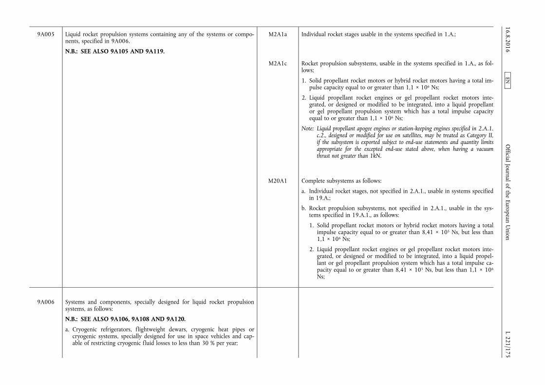
9A005 Liquid rocket propulsion systems containing any of the systems or components, specified in 9A006.
N.B.: SEE ALSO 9A105 AND 9A119.
M2A1a Individual rocket stages usable in the systems specified in 1.A.;
M2A1c Rocket propulsion subsystems, usable in the systems specified in 1.A., as follows;
1. Solid propellant rocket motors or hybrid rocket motors having a total impulse capacity equal to or greater than 1,1 × 10⁶ Ns;
2. Liquid propellant rocket engines or gel propellant rocket motors integrated, or designed or modified to be integrated, into a liquid propellant or gel propellant propulsion system which has a total impulse capacity equal to or greater than 1,1 × 10⁶ Ns;
Note: Liquid propellant apogee engines or station-keeping engines specified in 2.A.1. c.2., designed or modified for use on satellites, may be treated as Category II, if the subsystem is exported subject to end-use statements and quantity limits appropriate for the excepted end-use stated above, when having a vacuum thrust not greater than 1kN.
M20A1 Complete subsystems as follows:
a. Individual rocket stages, not specified in 2.A.1., usable in systems specified in 19.A.;
b. Rocket propulsion subsystems, not specified in 2.A.1., usable in the systems specified in 19.A.1., as follows:
1. Solid propellant rocket motors or hybrid rocket motors having a total impulse capacity equal to or greater than 8,41 × 10⁵ Ns, but less than 1,1 × 10⁶ Ns;
2. Liquid propellant rocket engines or gel propellant rocket motors integrated, or designed or modified to be integrated, into a liquid propellant or gel propellant propulsion system which has a total impulse capacity equal to or greater than 8,41 × 10⁵ Ns, but less than 1,1 × 10⁶
Ns;
9A006 Systems and components, specially designed for liquid rocket propulsion systems, as follows:
N.B.: SEE ALSO 9A106, 9A108 AND 9A120.
a. Cryogenic refrigerators, flightweight dewars, cryogenic heat pipes or cryogenic systems, specially designed for use in space vehicles and capable of restricting cryogenic fluid losses to less than 30 % per year;
16.8.2016 L 221/175
Official Journal of the European U
nion EN

b. Cryogenic containers or closed-cycle refrigeration systems, capable of providing temperatures of 100 K (–173 °C) or less for “aircraft” capable of sustained flight at speeds exceeding Mach 3, launch vehicles or “spacecraft”;
c. Slush hydrogen storage or transfer systems;
d. High pressure (exceeding 17,5 MPa) turbo pumps, pump components or their associated gas generator or expander cycle turbine drive systems;
M3A8 Liquid propellant tanks specially designed for the propellants controlled in Item 4.C. or other liquid propellants used in the systems specified in 1.A.1.
M3A5 Liquid, slurry and gel propellant (including oxidisers) control systems, and specially designed components therefor, usable in the systems specified in 1. A., designed or modified to operate in vibration environments greater than 10 g rms between 20 Hz and 2 kHz.
Notes:
1. The only servo valves, pumps and gas turbines specified in 3.A.5. are the following:
a. Servo valves designed for flow rates equal to or greater than 24 litres per minute, at an absolute pressure equal to or greater than 7 MPa, that have an actuator response time of less than 100 ms.
b. Pumps, for liquid propellants, with shaft speeds equal to or greater than 8 000 rpm at the maximum operating mode or with discharge pressures equal to or greater than 7 MPa.
c. Gas turbines, for liquid propellant turbopumps, with shaft speeds equal to or greater than 8 000 rpm at the maximum operating mode.
2. Systems and components specified in 3.A.5. may be exported as part of a satellite.
e. High-pressure (exceeding 10,6 MPa) thrust chambers and nozzles therefor;
M3A10 Combustion chambers and nozzles for liquid propellant rocket engines usable in the subsystems specified in 2.A.1.c.2. or 20.A.1.b.2.
f. Propellant storage systems using the principle of capillary containment or positive expulsion (i.e., with flexible bladders);
M3A8
g. Liquid propellant injectors with individual orifices of 0,381 mm or smaller in diameter (an area of 1,14 × 10⁻³ cm2 or smaller for non-circular orifices) and specially designed for liquid rocket engines;
M3A5
h. One-piece carbon-carbon thrust chambers or one-piece carbon-carbon exit cones, with densities exceeding 1,4 g/cm3 and tensile strengths exceeding 48 MPa.
M3A10 16.8.2016 L 221/176
Official Journal of the European U
nion EN

9A007 Solid rocket propulsion systems having any of the following:
N.B.: SEE ALSO 9A107 AND 9A119.
a. Total impulse capacity exceeding 1,1 MNs;
b. Specific impulse of 2,4 kNs/kg or more, when the nozzle flow is expanded to ambient sea level conditions for an adjusted chamber pressure of 7 MPa;
c. Stage mass fractions exceeding 88 % and propellant solid loadings exceeding 86 %;
d. Components specified in 9A008; or
e. Insulation and propellant bonding systems, using direct-bonded motor designs to provide a ‘strong mechanical bond’ or a barrier to chemical migration between the solid propellant and case insulation material.
Technical Note:
‘Strong mechanical bond’ means bond strength equal to or more than propellant strength.
M2A1 Complete subsystems usable in the systems specified in 1.A., as follows:
a. Individual rocket stages usable in the systems specified in 1.A.;
b. Re-entry vehicles, and equipment designed or modified therefor, usable in the systems specified in 1.A., as follows, except as provided in the Note below 2.A.1. for those designed for non-weapon payloads:
1. Heat shields, and components therefor, fabricated of ceramic or ablative materials;
2. Heat sinks and components therefor, fabricated of light-weight, high heat capacity materials;
3. Electronic equipment specially designed for re-entry vehicles;
c. Rocket propulsion subsystems, usable in the systems specified in 1.A., as follows;
1. Solid propellant rocket motors or hybrid rocket motors having a total impulse capacity equal to or greater than 1,1 × 10⁶ Ns;
2. Liquid propellant rocket engines or gel propellant rocket motors integrated, or designed or modified to be integrated, into a liquid propellant or gel propellant propulsion system which has a total impulse capacity equal to or greater than 1,1 × 10⁶ Ns;
Note: Liquid propellant apogee engines or station-keeping engines specified in 2. A.1.c.2., designed or modified for use on satellites, may be treated as Category II, if the subsystem is exported subject to end-use statements and quantity limits appropriate for the excepted end-use stated above, when having a vacuum thrust not greater than 1kN.
d. ‘Guidance sets’, usable in the systems specified in 1.A., capable of achieving system accuracy of 3,33 % or less of the “range” (e.g. a ‘CEP’ of 10 km or less at a “range” of 300 km), except as provided in the Note below 2. A.1. for those designed for missiles with a “range” under 300 km or manned aircraft;
16.8.2016 L 221/177
Official Journal of the European U
nion EN
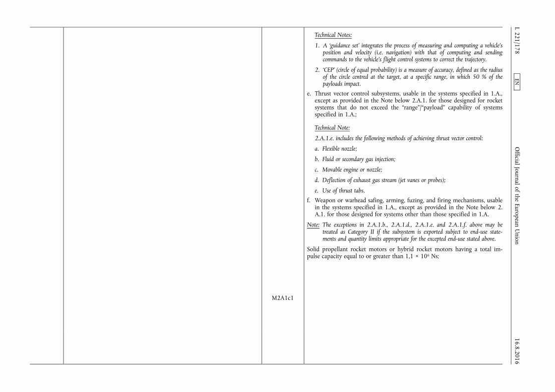
Technical Notes:
1. A ‘guidance set’ integrates the process of measuring and computing a vehicle's position and velocity (i.e. navigation) with that of computing and sending commands to the vehicle's flight control systems to correct the trajectory.
2. ‘CEP’ (circle of equal probability) is a measure of accuracy, defined as the radius of the circle centred at the target, at a specific range, in which 50 % of the payloads impact.
e. Thrust vector control subsystems, usable in the systems specified in 1.A., except as provided in the Note below 2.A.1. for those designed for rocket systems that do not exceed the “range”/“payload” capability of systems specified in 1.A.;
Technical Note:
2.A.1.e. includes the following methods of achieving thrust vector control:
a. Flexible nozzle;
b. Fluid or secondary gas injection;
c. Movable engine or nozzle;
d. Deflection of exhaust gas stream (jet vanes or probes);
e. Use of thrust tabs.
f. Weapon or warhead safing, arming, fuzing, and firing mechanisms, usable in the systems specified in 1.A., except as provided in the Note below 2. A.1. for those designed for systems other than those specified in 1.A.
Note: The exceptions in 2.A.1.b., 2.A.1.d., 2.A.1.e. and 2.A.1.f. above may be treated as Category II if the subsystem is exported subject to end-use statements and quantity limits appropriate for the excepted end-use stated above.
Solid propellant rocket motors or hybrid rocket motors having a total impulse capacity equal to or greater than 1,1 × 10⁶ Ns;
M2A1c1
16.8.2016 L 221/178
Official Journal of the European U
nion EN
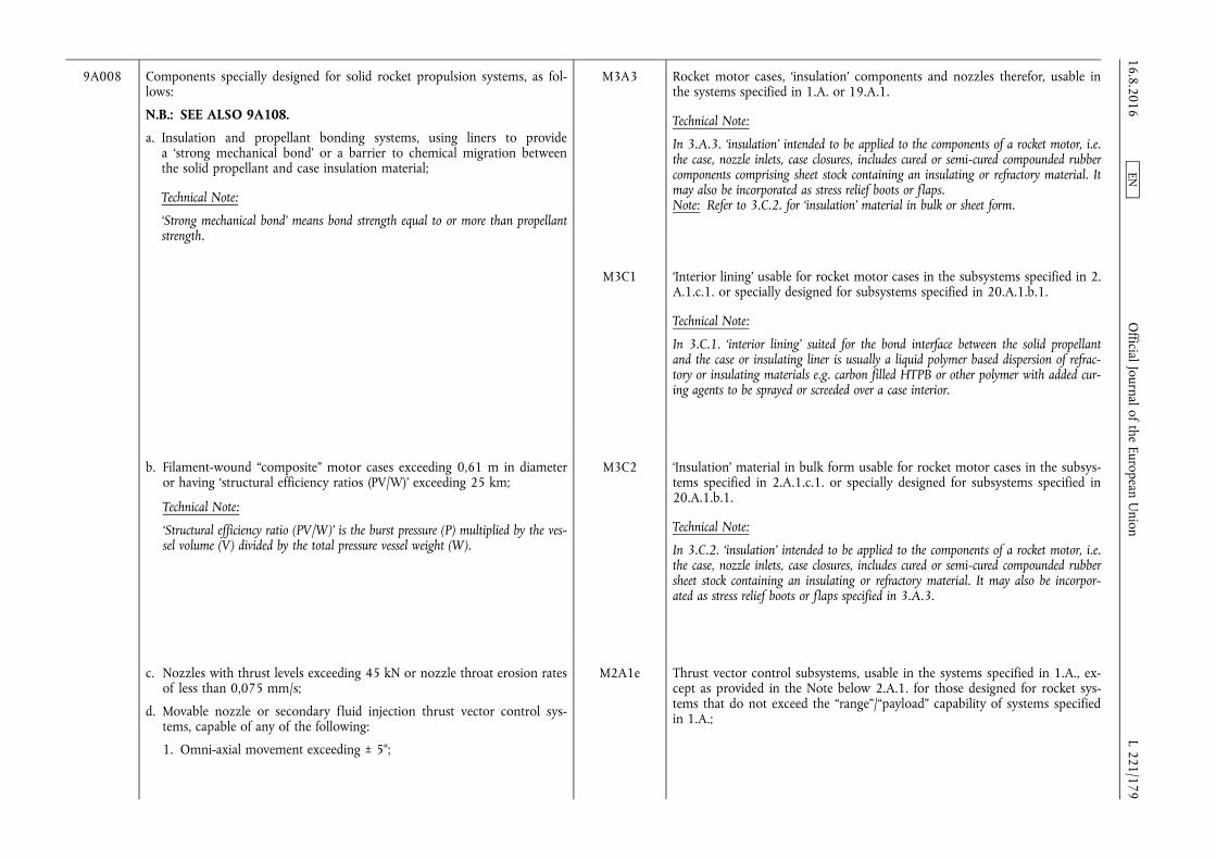
9A008 Components specially designed for solid rocket propulsion systems, as follows:
N.B.: SEE ALSO 9A108.
a. Insulation and propellant bonding systems, using liners to provide a ‘strong mechanical bond’ or a barrier to chemical migration between the solid propellant and case insulation material;
Technical Note:
‘Strong mechanical bond’ means bond strength equal to or more than propellant strength.
M3A3 Rocket motor cases, ‘insulation’ components and nozzles therefor, usable in the systems specified in 1.A. or 19.A.1.
Technical Note:
In 3.A.3. ‘insulation’ intended to be applied to the components of a rocket motor, i.e. the case, nozzle inlets, case closures, includes cured or semi-cured compounded rubber components comprising sheet stock containing an insulating or refractory material. It may also be incorporated as stress relief boots or flaps. Note: Refer to 3.C.2. for ‘insulation’ material in bulk or sheet form.
M3C1 ‘Interior lining’ usable for rocket motor cases in the subsystems specified in 2. A.1.c.1. or specially designed for subsystems specified in 20.A.1.b.1.
Technical Note:
In 3.C.1. ‘interior lining’ suited for the bond interface between the solid propellant and the case or insulating liner is usually a liquid polymer based dispersion of refractory or insulating materials e.g. carbon filled HTPB or other polymer with added curing agents to be sprayed or screeded over a case interior.
b. Filament-wound “composite” motor cases exceeding 0,61 m in diameter or having ‘structural efficiency ratios (PV/W)’ exceeding 25 km;
Technical Note:
‘Structural efficiency ratio (PV/W)’ is the burst pressure (P) multiplied by the vessel volume (V) divided by the total pressure vessel weight (W).
M3C2 ‘Insulation’ material in bulk form usable for rocket motor cases in the subsystems specified in 2.A.1.c.1. or specially designed for subsystems specified in 20.A.1.b.1.
Technical Note:
In 3.C.2. ‘insulation’ intended to be applied to the components of a rocket motor, i.e. the case, nozzle inlets, case closures, includes cured or semi-cured compounded rubber sheet stock containing an insulating or refractory material. It may also be incorporated as stress relief boots or flaps specified in 3.A.3.
c. Nozzles with thrust levels exceeding 45 kN or nozzle throat erosion rates of less than 0,075 mm/s;
d. Movable nozzle or secondary fluid injection thrust vector control systems, capable of any of the following:
1. Omni-axial movement exceeding ± 5°;
M2A1e Thrust vector control subsystems, usable in the systems specified in 1.A., except as provided in the Note below 2.A.1. for those designed for rocket systems that do not exceed the “range”/“payload” capability of systems specified in 1.A.;
16.8.2016 L 221/179
Official Journal of the European U
nion EN
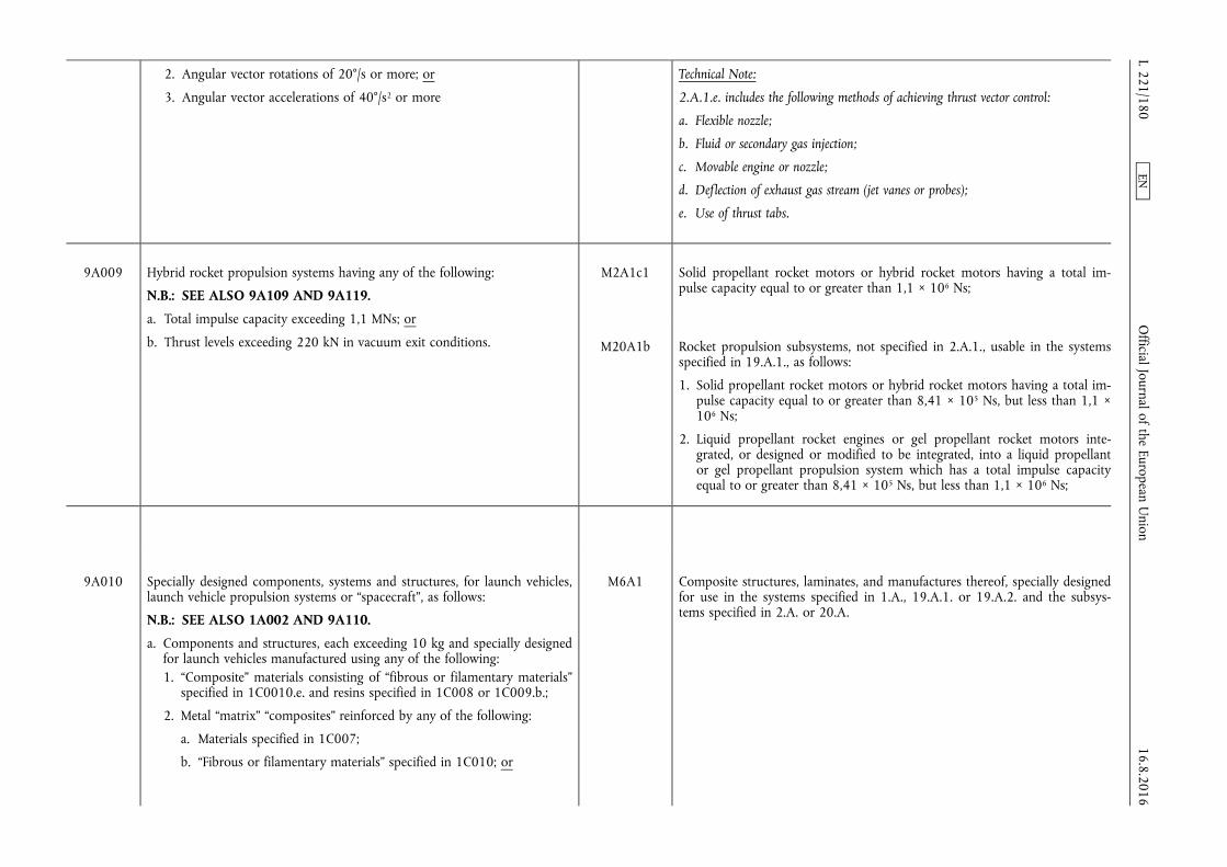
2. Angular vector rotations of 20°/s or more; or
3. Angular vector accelerations of 40°/s2 or more
Technical Note:
2.A.1.e. includes the following methods of achieving thrust vector control:
a. Flexible nozzle;
b. Fluid or secondary gas injection;
c. Movable engine or nozzle;
d. Deflection of exhaust gas stream (jet vanes or probes);
e. Use of thrust tabs.
9A009 Hybrid rocket propulsion systems having any of the following:
N.B.: SEE ALSO 9A109 AND 9A119.
a. Total impulse capacity exceeding 1,1 MNs; or
b. Thrust levels exceeding 220 kN in vacuum exit conditions.
M2A1c1 Solid propellant rocket motors or hybrid rocket motors having a total impulse capacity equal to or greater than 1,1 × 10⁶ Ns;
M20A1b Rocket propulsion subsystems, not specified in 2.A.1., usable in the systems specified in 19.A.1., as follows:
1. Solid propellant rocket motors or hybrid rocket motors having a total impulse capacity equal to or greater than 8,41 × 10⁵ Ns, but less than 1,1 × 10⁶ Ns;
2. Liquid propellant rocket engines or gel propellant rocket motors integrated, or designed or modified to be integrated, into a liquid propellant or gel propellant propulsion system which has a total impulse capacity equal to or greater than 8,41 × 10⁵ Ns, but less than 1,1 × 10⁶ Ns;
9A010 Specially designed components, systems and structures, for launch vehicles, launch vehicle propulsion systems or “spacecraft”, as follows:
N.B.: SEE ALSO 1A002 AND 9A110.
a. Components and structures, each exceeding 10 kg and specially designed for launch vehicles manufactured using any of the following: 1. “Composite” materials consisting of “fibrous or filamentary materials”
specified in 1C0010.e. and resins specified in 1C008 or 1C009.b.;
2. Metal “matrix” “composites” reinforced by any of the following:
a. Materials specified in 1C007;
b. “Fibrous or filamentary materials” specified in 1C010; or
M6A1 Composite structures, laminates, and manufactures thereof, specially designed for use in the systems specified in 1.A., 19.A.1. or 19.A.2. and the subsystems specified in 2.A. or 20.A.
16.8.2016 L 221/180
Official Journal of the European U
nion EN
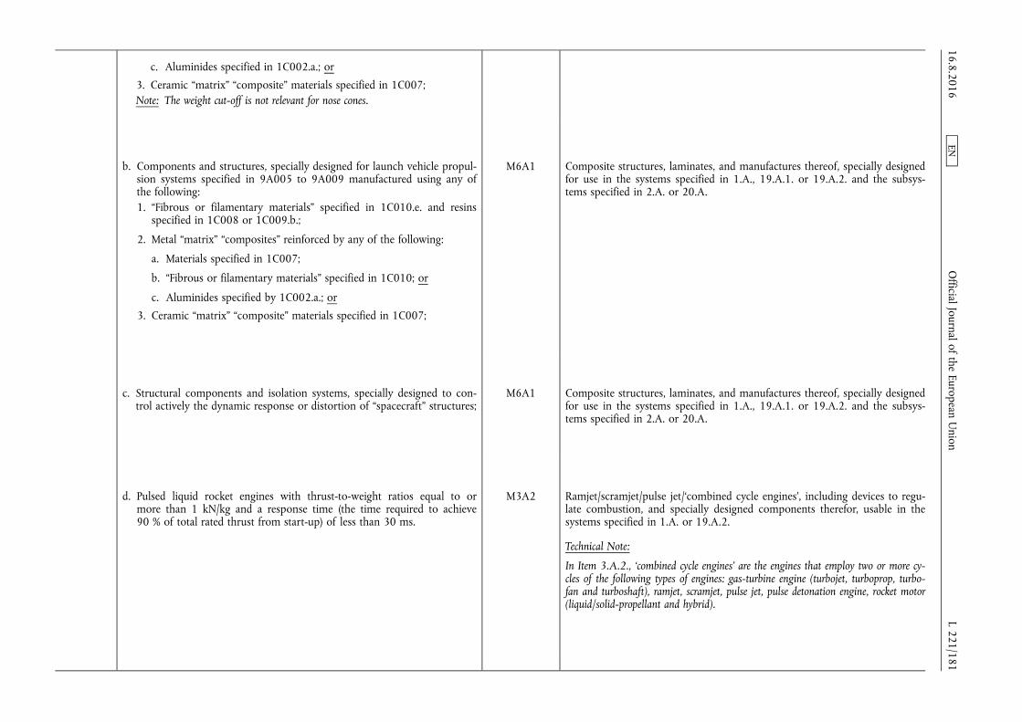
c. Aluminides specified in 1C002.a.; or
3. Ceramic “matrix” “composite” materials specified in 1C007; Note: The weight cut-off is not relevant for nose cones.
b. Components and structures, specially designed for launch vehicle propulsion systems specified in 9A005 to 9A009 manufactured using any of the following: 1. “Fibrous or filamentary materials” specified in 1C010.e. and resins
specified in 1C008 or 1C009.b.;
2. Metal “matrix” “composites” reinforced by any of the following:
a. Materials specified in 1C007;
b. “Fibrous or filamentary materials” specified in 1C010; or
c. Aluminides specified by 1C002.a.; or
3. Ceramic “matrix” “composite” materials specified in 1C007;
M6A1 Composite structures, laminates, and manufactures thereof, specially designed for use in the systems specified in 1.A., 19.A.1. or 19.A.2. and the subsystems specified in 2.A. or 20.A.
c. Structural components and isolation systems, specially designed to control actively the dynamic response or distortion of “spacecraft” structures;
M6A1 Composite structures, laminates, and manufactures thereof, specially designed for use in the systems specified in 1.A., 19.A.1. or 19.A.2. and the subsystems specified in 2.A. or 20.A.
d. Pulsed liquid rocket engines with thrust-to-weight ratios equal to or more than 1 kN/kg and a response time (the time required to achieve 90 % of total rated thrust from start-up) of less than 30 ms.
M3A2 Ramjet/scramjet/pulse jet/‘combined cycle engines’, including devices to regulate combustion, and specially designed components therefor, usable in the systems specified in 1.A. or 19.A.2.
Technical Note:
In Item 3.A.2., ‘combined cycle engines’ are the engines that employ two or more cycles of the following types of engines: gas-turbine engine (turbojet, turboprop, turbofan and turboshaft), ramjet, scramjet, pulse jet, pulse detonation engine, rocket motor (liquid/solid-propellant and hybrid).
16.8.2016 L 221/181
Official Journal of the European U
nion EN
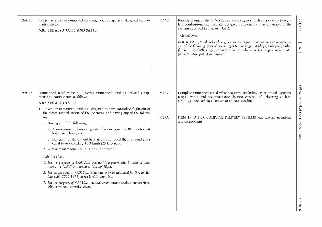
9A011 Ramjet, scramjet or combined cycle engines, and specially designed components therefor.
N.B.: SEE ALSO 9A111 AND 9A118.
M3A2 Ramjet/scramjet/pulse jet/‘combined cycle engines’, including devices to regulate combustion, and specially designed components therefor, usable in the systems specified in 1.A. or 19.A.2.
Technical Note:
In Item 3.A.2., ‘combined cycle engines’ are the engines that employ two or more cycles of the following types of engines: gas-turbine engine (turbojet, turboprop, turbofan and turboshaft), ramjet, scramjet, pulse jet, pulse detonation engine, rocket motor (liquid/solid-propellant and hybrid).
9A012 “Unmanned aerial vehicles” (“UAVs”), unmanned “airships”, related equipment and components, as follows:
N.B.: SEE ALSO 9A112.
a. “UAVs” or unmanned “airships”, designed to have controlled flight out of the direct ‘natural vision’ of the ‘operator’ and having any of the following:
1. Having all of the following:
a. A maximum ‘endurance’ greater than or equal to 30 minutes but less than 1 hour; and
b. Designed to take-off and have stable controlled flight in wind gusts equal to or exceeding 46,3 km/h (25 knots); or
2. A maximum ‘endurance’ of 1 hour or greater;
Technical Notes:
1. For the purposes of 9A012.a., ‘operator’ is a person who initiates or commands the “UAV” or unmanned “airship” flight.
2. For the purposes of 9A012.a., ‘endurance’ is to be calculated for ISA conditions (ISO 2533:1975) at sea level in zero wind.
3. For the purposes of 9A012.a., ‘natural vision’ means unaided human sight, with or without corrective lenses.
M1A2 Complete unmanned aerial vehicle systems (including cruise missile systems, target drones and reconnaissance drones) capable of delivering at least a 500 kg “payload” to a “range” of at least 300 km.
M19A ITEM 19 OTHER COMPLETE DELIVERY SYSTEMS: equipment, assemblies and components
16.8.2016 L 221/182
Official Journal of the European U
nion EN
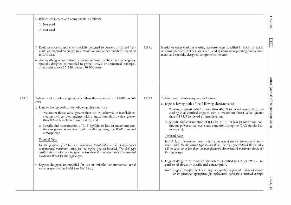
b. Related equipment and components, as follows:
1. Not used
2. Not used
3. Equipment or components, specially designed to convert a manned “aircraft” or manned “airship”, to a “UAV” or unmanned “airship”, specified in 9A012.a.;
4. Air breathing reciprocating or rotary internal combustion type engines, specially designed or modified to propel “UAVs” or unmanned “airships”, at altitudes above 15 240 metres (50 000 feet).
M9A6 Inertial or other equipment using accelerometers specified in 9.A.3. or 9.A.5. or gyros specified in 9.A.4. or 9.A.5., and systems incorporating such equipment, and specially designed components therefor.
9A101 Turbojet and turbofan engines, other than those specified in 9A001, as follows;
a. Engines having both of the following characteristics:
1. ‘Maximum thrust value’ greater than 400 N (achieved un-installed) excluding civil certified engines with a ‘maximum thrust value’ greater than 8 890 N (achieved un-installed), and
2. Specific fuel consumption of 0,15 kg/N/hr or less (at maximum continuous power at sea level static conditions using the ICAO standard atmosphere);
Technical Note:
For the purpose of 9A101.a.1. ‘maximum thrust value’ is the manufacturer's demonstrated maximum thrust for the engine type un-installed. The civil type certified thrust value will be equal or less than the manufacturer's demonstrated maximum thrust for the engine type.
b. Engines designed or modified for use in “missiles” or unmanned aerial vehicles specified in 9A012 or 9A112.a.,
M3A1 Turbojet and turbofan engines, as follows:
a. Engines having both of the following characteristics:
1. ‘Maximum thrust value’ greater than 400 N (achieved un-installed) excluding civil certified engines with a ‘maximum thrust value’ greater than 8,89 kN (achieved un-installed); and
2. Specific fuel consumption of 0,15 kg N–1 h–1 or less (at maximum continuous power at sea level static conditions using the ICAO standard atmosphere);
Technical Note:
In 3.A.1.a.1., ‘maximum thrust value’ is the manufacturer's demonstrated maximum thrust for the engine type un-installed. The civil type certified thrust value will be equal to or less than the manufacturer's demonstrated maximum thrust for the engine type.
b. Engines designed or modified for systems specified in 1.A. or 19.A.2., regardless of thrust or specific fuel consumption.
Note: Engines specified in 3.A.1. may be exported as part of a manned aircraft or in quantities appropriate for replacement parts for a manned aircraft.
16.8.2016 L 221/183
Official Journal of the European U
nion EN
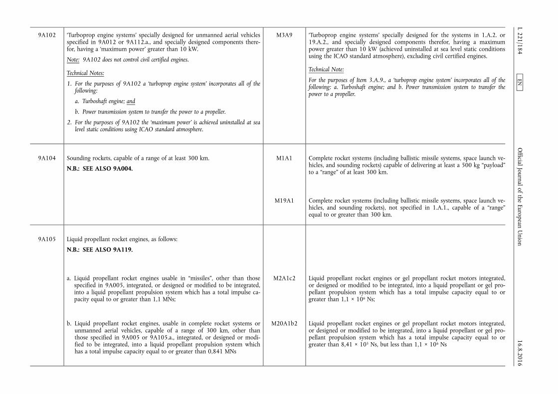
9A102 ‘Turboprop engine systems’ specially designed for unmanned aerial vehicles specified in 9A012 or 9A112.a., and specially designed components therefor, having a ‘maximum power’ greater than 10 kW.
Note: 9A102 does not control civil certified engines.
Technical Notes:
1. For the purposes of 9A102 a ‘turboprop engine system’ incorporates all of the following:
a. Turboshaft engine; and
b. Power transmission system to transfer the power to a propeller.
2. For the purposes of 9A102 the ‘maximum power’ is achieved uninstalled at sea level static conditions using ICAO standard atmosphere.
M3A9 ‘Turboprop engine systems’ specially designed for the systems in 1.A.2. or 19.A.2., and specially designed components therefor, having a maximum power greater than 10 kW (achieved uninstalled at sea level static conditions using the ICAO standard atmosphere), excluding civil certified engines.
Technical Note:
For the purposes of Item 3.A.9., a ‘turboprop engine system’ incorporates all of the following: a. Turboshaft engine; and b. Power transmission system to transfer the power to a propeller.
9A104 Sounding rockets, capable of a range of at least 300 km.
N.B.: SEE ALSO 9A004.
M1A1 Complete rocket systems (including ballistic missile systems, space launch vehicles, and sounding rockets) capable of delivering at least a 500 kg “payload” to a “range” of at least 300 km.
M19A1 Complete rocket systems (including ballistic missile systems, space launch vehicles, and sounding rockets), not specified in 1.A.1., capable of a “range” equal to or greater than 300 km.
9A105 Liquid propellant rocket engines, as follows:
N.B.: SEE ALSO 9A119.
a. Liquid propellant rocket engines usable in “missiles”, other than those specified in 9A005, integrated, or designed or modified to be integrated, into a liquid propellant propulsion system which has a total impulse capacity equal to or greater than 1,1 MNs;
M2A1c2 Liquid propellant rocket engines or gel propellant rocket motors integrated, or designed or modified to be integrated, into a liquid propellant or gel propellant propulsion system which has a total impulse capacity equal to or greater than 1,1 × 10⁶ Ns;
b. Liquid propellant rocket engines, usable in complete rocket systems or unmanned aerial vehicles, capable of a range of 300 km, other than those specified in 9A005 or 9A105.a., integrated, or designed or modified to be integrated, into a liquid propellant propulsion system which has a total impulse capacity equal to or greater than 0,841 MNs
M20A1b2 Liquid propellant rocket engines or gel propellant rocket motors integrated, or designed or modified to be integrated, into a liquid propellant or gel propellant propulsion system which has a total impulse capacity equal to or greater than 8,41 × 10⁵ Ns, but less than 1,1 × 10⁶ Ns
16.8.2016 L 221/184
Official Journal of the European U
nion EN

9A106 Systems or components, other than those specified in 9A006 as follows, specially designed for liquid rocket propulsion systems:
a. Ablative liners for thrust or combustion chambers, usable in “missiles”, space launch vehicles specified in 9A004 or sounding rockets specified in 9A104;
b. Rocket nozzles, usable in “missiles”, space launch vehicles specified in 9A004 or sounding rockets specified in 9A104;
M3A3 Rocket motor cases, ‘insulation’ components and nozzles therefor, usable in the systems specified in 1.A. or 19.A.1.
Technical Note:
In 3.A.3. ‘insulation’ intended to be applied to the components of a rocket motor, i.e. the case, nozzle inlets, case closures, includes cured or semi-cured compounded rubber components comprising sheet stock containing an insulating or refractory material. It may also be incorporated as stress relief boots or flaps. Note: Refer to 3.C.2. for ‘insulation’ material in bulk or sheet form.
c. Thrust vector control sub-systems, usable in “missiles”;
Technical Note:
Examples of methods of achieving thrust vector control specified in 9A106.c. are:
1. Flexible nozzle;
2. Fluid or secondary gas injection;
3. Movable engine or nozzle;
4. Deflection of exhaust gas stream (jet vanes or probes); or
5. Thrust tabs.
M2A1e Thrust vector control subsystems, usable in the systems specified in 1.A., except as provided in the Note below 2.A.1. for those designed for rocket systems that do not exceed the “range”/“payload” capability of systems specified in 1.A.; Technical
Technical Note:
2.A.1.e. includes the following methods of achieving thrust vector control:
a. Flexible nozzle;
b. Fluid or secondary gas injection;
c. Movable engine or nozzle;
d. Deflection of exhaust gas stream (jet vanes or probes);
e. Use of thrust tabs.
d. Liquid, slurry and gel propellant (including oxidisers) control systems, and specially designed components therefor, usable in “missiles”, designed or modified to operate in vibration environments greater than 10 g rms between 20 Hz and 2 kHz; Note: The only servo valves, pumps and gas turbines specified in 9A106.d., are
the following:
a. Servo valves designed for flow rates equal to or greater than 24 litres per minute, at an absolute pressure equal to or greater than 7 MPa, that have an actuator response time of less than 100 ms;
b. Pumps, for liquid propellants, with shaft speeds equal to or greater than 8 000 r.p.m. at a maximum operating mode or with discharge pressures equal to or greater than 7 MPa.
M3A5 Liquid, slurry and gel propellant (including oxidisers) control systems, and specially designed components therefor, usable in the systems specified in 1. A., designed or modified to operate in vibration environments greater than 10 g rms between 20 Hz and 2 kHz.
Notes:
1. The only servo valves, pumps and gas turbines specified in 3.A.5. are the following:
a. Servo valves designed for flow rates equal to or greater than 24 litres per minute, at an absolute pressure equal to or greater than 7 MPa, that have an actuator response time of less than 100 ms.
b. Pumps, for liquid propellants, with shaft speeds equal to or greater than 8 000 rpm at the maximum operating mode or with discharge pressures equal to or greater than 7 MPa.
16.8.2016 L 221/185
Official Journal of the European U
nion EN
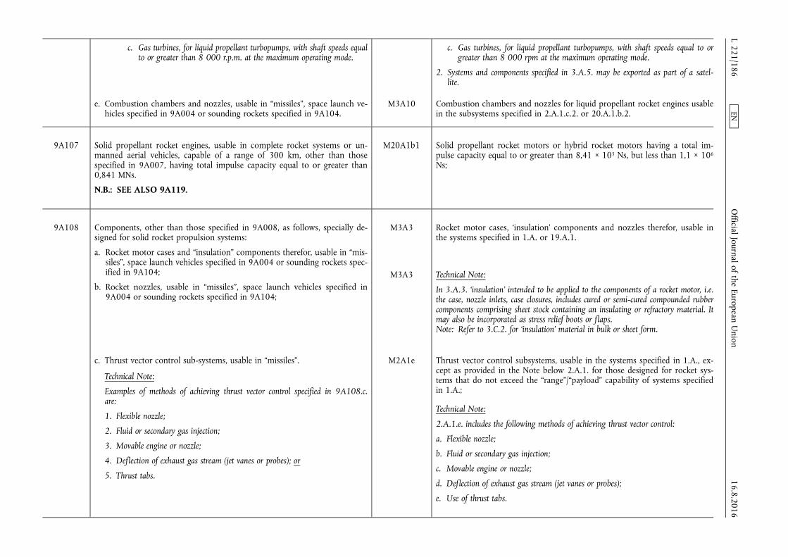
c. Gas turbines, for liquid propellant turbopumps, with shaft speeds equal to or greater than 8 000 r.p.m. at the maximum operating mode.
c. Gas turbines, for liquid propellant turbopumps, with shaft speeds equal to or greater than 8 000 rpm at the maximum operating mode.
2. Systems and components specified in 3.A.5. may be exported as part of a satellite.
e. Combustion chambers and nozzles, usable in “missiles”, space launch vehicles specified in 9A004 or sounding rockets specified in 9A104.
M3A10 Combustion chambers and nozzles for liquid propellant rocket engines usable in the subsystems specified in 2.A.1.c.2. or 20.A.1.b.2.
9A107 Solid propellant rocket engines, usable in complete rocket systems or unmanned aerial vehicles, capable of a range of 300 km, other than those specified in 9A007, having total impulse capacity equal to or greater than 0,841 MNs.
N.B.: SEE ALSO 9A119.
M20A1b1 Solid propellant rocket motors or hybrid rocket motors having a total impulse capacity equal to or greater than 8,41 × 10⁵ Ns, but less than 1,1 × 10⁶
Ns;
9A108 Components, other than those specified in 9A008, as follows, specially designed for solid rocket propulsion systems:
a. Rocket motor cases and “insulation” components therefor, usable in “missiles”, space launch vehicles specified in 9A004 or sounding rockets specified in 9A104;
b. Rocket nozzles, usable in “missiles”, space launch vehicles specified in 9A004 or sounding rockets specified in 9A104;
M3A3 Rocket motor cases, ‘insulation’ components and nozzles therefor, usable in the systems specified in 1.A. or 19.A.1.
M3A3 Technical Note:
In 3.A.3. ‘insulation’ intended to be applied to the components of a rocket motor, i.e. the case, nozzle inlets, case closures, includes cured or semi-cured compounded rubber components comprising sheet stock containing an insulating or refractory material. It may also be incorporated as stress relief boots or flaps. Note: Refer to 3.C.2. for ‘insulation’ material in bulk or sheet form.
c. Thrust vector control sub-systems, usable in “missiles”.
Technical Note:
Examples of methods of achieving thrust vector control specified in 9A108.c. are:
1. Flexible nozzle;
2. Fluid or secondary gas injection;
3. Movable engine or nozzle;
4. Deflection of exhaust gas stream (jet vanes or probes); or
5. Thrust tabs.
M2A1e Thrust vector control subsystems, usable in the systems specified in 1.A., except as provided in the Note below 2.A.1. for those designed for rocket systems that do not exceed the “range”/“payload” capability of systems specified in 1.A.;
Technical Note:
2.A.1.e. includes the following methods of achieving thrust vector control:
a. Flexible nozzle;
b. Fluid or secondary gas injection;
c. Movable engine or nozzle;
d. Deflection of exhaust gas stream (jet vanes or probes);
e. Use of thrust tabs.
16.8.2016 L 221/186
Official Journal of the European U
nion EN

9A109 Hybrid rocket motors and specially designed components as follows:
a. Hybrid rocket motors usable in complete rocket systems or unmanned aerial vehicles, capable of 300 km, other than those specified in 9A009, having a total impulse capacity equal to or greater than 0,841 MNs, and specially designed components therefor;
b. Specially designed components for hybrid rocket motors specified in 9A009 that are usable in “missiles”.
N.B.: SEE ALSO 9A009 and 9A119.
M3A6 Specially designed components for hybrid rocket motors specified in 2.A.1. c.1. and 20.A.1.b.1.
M20A1b Rocket propulsion subsystems, not specified in 2.A.1., usable in the systems specified in 19.A.1., as follows:
1. Solid propellant rocket motors or hybrid rocket motors having a total impulse capacity equal to or greater than 8,41 × 10⁵ Ns, but less than 1,1 × 10⁶ Ns;
2. Liquid propellant rocket engines or gel propellant rocket motors integrated, or designed or modified to be integrated, into a liquid propellant or gel propellant propulsion system which has a total impulse capacity equal to or greater than 8,41 × 10⁵ Ns, but less than 1,1 × 10⁶ Ns;
M2A1c Rocket propulsion subsystems, usable in the systems specified in 1.A., as follows;
1. Solid propellant rocket motors or hybrid rocket motors having a total impulse capacity equal to or greater than 1,1 × 10⁶ Ns;
2. Liquid propellant rocket engines or gel propellant rocket motors integrated, or designed or modified to be integrated, into a liquid propellant or gel propellant propulsion system which has a total impulse capacity equal to or greater than 1,1 × 10⁶ Ns;
Note: Liquid propellant apogee engines or station-keeping engines specified in 2. A.1.c.2., designed or modified for use on satellites, may be treated as Category II, if the subsystem is exported subject to end-use statements and quantity limits appropriate for the excepted end-use stated above, when having a vacuum thrust not greater than 1kN.
9A110 Composite structures, laminates and manufactures thereof, other than those specified in 9A010, specially designed for use in ‘missiles’ or the subsystems specified in 9A005, 9A007, 9A105, 9A106.c., 9A107, 9A108.c., 9A116 or 9A119.
N.B.: SEE ALSO 1A002.
Technical Note:
In 9A110 ‘missile’ means complete rocket systems and unmanned aerial vehicle systems capable of a range exceeding 300 km.
M6A1 Composite structures, laminates, and manufactures thereof, specially designed for use in the systems specified in 1.A., 19.A.1. or 19.A.2. and the subsystems specified in 2.A. or 20.A.
16.8.2016 L 221/187
Official Journal of the European U
nion EN
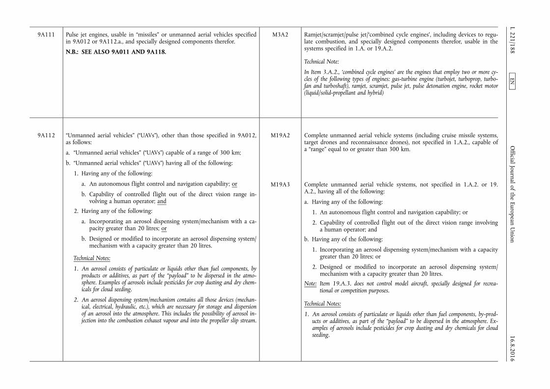
9A111 Pulse jet engines, usable in “missiles” or unmanned aerial vehicles specified in 9A012 or 9A112.a., and specially designed components therefor.
N.B.: SEE ALSO 9A011 AND 9A118.
M3A2 Ramjet/scramjet/pulse jet/‘combined cycle engines’, including devices to regulate combustion, and specially designed components therefor, usable in the systems specified in 1.A. or 19.A.2.
Technical Note:
In Item 3.A.2., ‘combined cycle engines’ are the engines that employ two or more cycles of the following types of engines: gas-turbine engine (turbojet, turboprop, turbofan and turboshaft), ramjet, scramjet, pulse jet, pulse detonation engine, rocket motor (liquid/solid-propellant and hybrid)
9A112 “Unmanned aerial vehicles” (“UAVs”), other than those specified in 9A012, as follows:
a. “Unmanned aerial vehicles” (“UAVs”) capable of a range of 300 km;
b. “Unmanned aerial vehicles” (“UAVs”) having all of the following:
1. Having any of the following:
a. An autonomous flight control and navigation capability; or
b. Capability of controlled flight out of the direct vision range involving a human operator; and
2. Having any of the following:
a. Incorporating an aerosol dispensing system/mechanism with a capacity greater than 20 litres; or
b. Designed or modified to incorporate an aerosol dispensing system/ mechanism with a capacity greater than 20 litres.
Technical Notes:
1. An aerosol consists of particulate or liquids other than fuel components, by products or additives, as part of the “payload” to be dispersed in the atmosphere. Examples of aerosols include pesticides for crop dusting and dry chemicals for cloud seeding.
2. An aerosol dispensing system/mechanism contains all those devices (mechanical, electrical, hydraulic, etc.), which are necessary for storage and dispersion of an aerosol into the atmosphere. This includes the possibility of aerosol injection into the combustion exhaust vapour and into the propeller slip stream.
M19A2 Complete unmanned aerial vehicle systems (including cruise missile systems, target drones and reconnaissance drones), not specified in 1.A.2., capable of a “range” equal to or greater than 300 km.
M19A3 Complete unmanned aerial vehicle systems, not specified in 1.A.2. or 19. A.2., having all of the following:
a. Having any of the following:
1. An autonomous flight control and navigation capability; or
2. Capability of controlled flight out of the direct vision range involving a human operator; and
b. Having any of the following:
1. Incorporating an aerosol dispensing system/mechanism with a capacity greater than 20 litres; or
2. Designed or modified to incorporate an aerosol dispensing system/ mechanism with a capacity greater than 20 litres.
Note: Item 19.A.3. does not control model aircraft, specially designed for recreational or competition purposes.
Technical Notes:
1. An aerosol consists of particulate or liquids other than fuel components, by-products or additives, as part of the “payload” to be dispersed in the atmosphere. Examples of aerosols include pesticides for crop dusting and dry chemicals for cloud seeding. 16.8.2016
L 221/188 O
fficial Journal of the European Union
EN
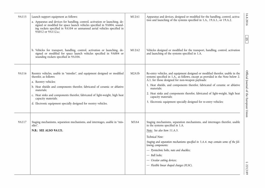
9A115 Launch support equipment as follows:
a. Apparatus and devices for handling, control, activation or launching, designed or modified for space launch vehicles specified in 9A004, sounding rockets specified in 9A104 or unmanned aerial vehicles specified in 9A012 or 9A112.a.;
M12A1 Apparatus and devices, designed or modified for the handling, control, activation and launching of the systems specified in 1.A., 19.A.1., or 19.A.2.
b. Vehicles for transport, handling, control, activation or launching, designed or modified for space launch vehicles specified in 9A004 or sounding rockets specified in 9A104.
M12A2 Vehicles designed or modified for the transport, handling, control, activation and launching of the systems specified in 1.A.
9A116 Reentry vehicles, usable in “missiles”, and equipment designed or modified therefor, as follows:
a. Reentry vehicles;
b. Heat shields and components therefor, fabricated of ceramic or ablative materials;
c. Heat sinks and components therefor, fabricated of light-weight, high heat capacity materials;
d. Electronic equipment specially designed for reentry vehicles.
M2A1b Re-entry vehicles, and equipment designed or modified therefor, usable in the systems specified in 1.A., as follows, except as provided in the Note below 2. A.1. for those designed for non-weapon payloads:
1. Heat shields, and components therefor, fabricated of ceramic or ablative materials;
2. Heat sinks and components therefor, fabricated of light-weight, high heat capacity materials;
3. Electronic equipment specially designed for re-entry vehicles;
9A117 Staging mechanisms, separation mechanisms, and interstages, usable in “missiles”.
N.B.: SEE ALSO 9A121.
M3A4 Staging mechanisms, separation mechanisms, and interstages therefor, usable in the systems specified in 1.A.
Note: See also Item 11.A.5.
Technical Note:
Staging and separation mechanisms specified in 3.A.4. may contain some of the following components:
— Pyrotechnic bolts, nuts and shackles;
— Ball locks;
— Circular cutting devices;
— Flexible linear shaped charges (FLSC).
16.8.2016 L 221/189
Official Journal of the European U
nion EN

9A118 Devices to regulate combustion usable in engines, which are usable in “missiles” or unmanned aerial vehicles specified in 9A012 or 9A112.a., specified in 9A011 or 9A111.
M3A2 Ramjet/scramjet/pulse jet/‘combined cycle engines’, including devices to regulate combustion, and specially designed components therefor, usable in the systems specified in 1.A. or 19.A.2.
Technical Note:
In Item 3.A.2., ‘combined cycle engines’ are the engines that employ two or more cycles of the following types of engines: gas-turbine engine (turbojet, turboprop, turbofan and turboshaft), ramjet, scramjet, pulse jet, pulse detonation engine, rocket motor (liquid/solid-propellant and hybrid).
9A119 Individual rocket stages, usable in complete rocket systems or unmanned aerial vehicles, capable of a range of 300 km, other than those specified in 9A005, 9A007, 9A009, 9A105, 9A107 and 9A109.
M2A1a Individual rocket stages usable in the systems specified in 1.A.;
M20A1a Complete subsystems as follows: a. Individual rocket stages, not specified in 2.A.1., usable in systems specified in 19.A.
9A120 Liquid propellant tanks, other than those specified in 9A006, specially designed for propellants specified in 1C111 or ‘other liquid propellants’, used in rocket systems capable of delivering at least a 500 kg payload to a range of at least 300 km.
M3A8 Liquid propellant tanks specially designed for the propellants controlled in Item 4.C. or other liquid propellants used in the systems specified in 1.A.1.
9A121 Umbilical and interstage electrical connectors specially designed for “missiles”, space launch vehicles specified in 9A004 or sounding rockets specified in 9A104.
Technical Note:
Interstage connectors referred to in 9A121 also include electrical connectors installed between the “missile”, space launch vehicle or sounding rocket and their payload.
M11A5 Umbilical and interstage electrical connectors specially designed for systems specified in 1.A.1. or 19.A.1.
Technical Note:
Interstage connectors referred to in 11.A.5. also include electrical connectors installed between systems specified in 1.A.1. or 19.A.1. and their “payload”.
16.8.2016 L 221/190
Official Journal of the European U
nion EN
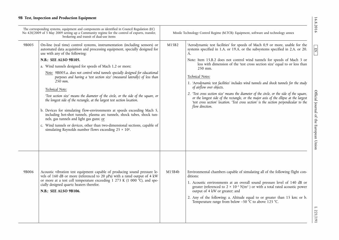
9B Test, Inspection and Production Equipment
The corresponding systems, equipment and components as identified in Council Regulation (EC) No 428/2009 of 5 May 2009 setting up a Community regime for the control of exports, transfer,
brokering and transit of dual-use items Missile Technology Control Regime (M.TCR): Equipment, software and technology annex
9B005 On-line (real time) control systems, instrumentation (including sensors) or automated data acquisition and processing equipment, specially designed for use with any of the following:
N.B.: SEE ALSO 9B105.
a. Wind tunnels designed for speeds of Mach 1,2 or more;
Note: 9B005.a. does not control wind tunnels specially designed for educational purposes and having a ‘test section size’ (measured laterally) of less than 250 mm.
Technical Note:
‘Test section size’ means the diameter of the circle, or the side of the square, or the longest side of the rectangle, at the largest test section location.
b. Devices for simulating flow-environments at speeds exceeding Mach 5, including hot-shot tunnels, plasma arc tunnels, shock tubes, shock tunnels, gas tunnels and light gas guns; or
c. Wind tunnels or devices, other than two-dimensional sections, capable of simulating Reynolds number flows exceeding 25 × 106.
M15B2 ‘Aerodynamic test facilities’ for speeds of Mach 0,9 or more, usable for the systems specified in 1.A. or 19.A. or the subsystems specified in 2.A. or 20. A.
Note: Item 15.B.2 does not control wind tunnels for speeds of Mach 3 or less with dimension of the ‘test cross section size’ equal to or less than 250 mm.
Technical Notes:
1. ‘Aerodynamic test facilities’ includes wind tunnels and shock tunnels for the study of airflow over objects.
2. ‘Test cross section size’ means the diameter of the circle, or the side of the square, or the longest side of the rectangle, or the major axis of the ellipse at the largest ‘test cross section’ location. ‘Test cross section’ is the section perpendicular to the flow direction.
9B006 Acoustic vibration test equipment capable of producing sound pressure levels of 160 dB or more (referenced to 20 µPa) with a rated output of 4 kW or more at a test cell temperature exceeding 1 273 K (1 000 °C), and specially designed quartz heaters therefor.
N.B.: SEE ALSO 9B106.
M15B4b Environmental chambers capable of simulating all of the following flight conditions:
1. Acoustic environments at an overall sound pressure level of 140 dB or greater (referenced to 2 × 10⁻⁵ N/m2 ) or with a total rated acoustic power output of 4 kW or greater; and
2. Any of the following: a. Altitude equal to or greater than 15 km; or b. Temperature range from below –50 °C to above 125 °C.
16.8.2016 L 221/191
Official Journal of the European U
nion EN
9B105 ‘Aerodynamic test facilities’ for speeds of Mach 0,9 or more, usable for ‘missiles’ and their subsystems.
N.B.: SEE ALSO 9B005.
Note: 9B105 does not control wind-tunnels for speeds of Mach 3 or less with dimension of the ‘test cross section size’ equal to or less than 250 mm.
Technical Notes:
1. In 9B105 ‘aerodynamic test facilities’ includes wind tunnels and shock tunnels for the study of airflow over objects.
2. In Note to 9B105, ‘test cross section size’ means the diameter of the circle, or the side of the square, or the longest side of the rectangle, or the major axis of the ellipse at the largest ‘test cross section’ location. ‘Test cross section’ is the section perpendicular to the flow direction.
3. In 9B105 ‘missile’ means complete rocket systems and unmanned aerial vehicle systems capable of a range exceeding 300 km.
M15B2 ‘Aerodynamic test facilities’ for speeds of Mach 0,9 or more, usable for the systems specified in 1.A. or 19.A. or the subsystems specified in 2.A. or 20. A.
Note: Item 15.B.2 does not control wind tunnels for speeds of Mach 3 or less with dimension of the ‘test cross section size’ equal to or less than 250 mm.
Technical Notes:
1. ‘Aerodynamic test facilities’ includes wind tunnels and shock tunnels for the study of airflow over objects.
2. ‘Test cross section size’ means the diameter of the circle, or the side of the square, or the longest side of the rectangle, or the major axis of the ellipse at the largest ‘test cross section’ location. ‘Test cross section’ is the section perpendicular to the flow direction.
9B106 Environmental chambers and anechoic chambers, as follows:
a. Environmental chambers capable of simulating all the following flight conditions:
1. Having any of the following:
a. Altitude equal to or greater than 15 km; or
b. Temperature range from below 223 K (–50 ° C) to above 398 K (+125 °C); and
2. Incorporating, or ‘designed or modified’ to incorporate, a shaker unit or other vibration test equipment to produce vibration environments equal to or greater than 10 g rms, measured ‘bare table’, between 20 Hz and 2 kHz while imparting forces equal to or greater than 5 kN;
M15B4 Environmental chambers as follows, usable for the systems specified in 1.A. or 19.A. or the subsystems specified in 2.A. or 20.A.:
a. Environmental chambers having all of the following characteristics:
1. Capable of simulating any of the following flight conditions:
a. Altitude equal to or greater than 15 km; or
b. Temperature range from below –50 °C to above 125 °C; and
2. Incorporating, or designed or modified to incorporate, a shaker unit or other vibration test equipment to produce vibration environments equal to or greater than 10 g rms, measured ‘bare table’, between 20 Hz and 2 kHz while imparting forces equal to or greater than 5 kN;
16.8.2016 L 221/192
Official Journal of the European U
nion EN
Technical Notes:
1. 9B106.a.2. describes systems that are capable of generating a vibration environment with a single wave (e.g., a sine wave) and systems capable of generating a broad band random vibration (i.e., power spectrum).
2. In 9B106.a.2., ‘designed or modified’ means the environmental chamber provides appropriate interfaces (e.g., sealing devices) to incorporate a shaker unit or other vibration test equipment as specified in 2B116.
3. In 9B106.a.2. ‘bare table’ means a flat table, or surface, with no fixture or fittings.
b. Environmental chambers capable of simulating the following flight conditions:
1. Acoustic environments at an overall sound pressure level of 140 dB or greater (referenced to 20 µPa) or with a total rated acoustic power output of 4 kW or greater; and
2. Altitude equal to or greater than 15 km; or
3. Temperature range from below 223 K (–50 °C) to above 398 K (+125 °C).
Technical Notes:
1. Item 15.B.4.a.2. describes systems that are capable of generating a vibration environment with a single wave (e.g. a sine wave) and systems capable of generating a broad band random vibration (i.e. power spectrum).
2. In Item 15.B.4.a.2., designed or modified means the environmental chamber provides appropriate interfaces (e.g. sealing devices) to incorporate a shaker unit or other vibration test equipment as specified in this Item.
b. Environmental chambers capable of simulating all of the following flight conditions:
1. Acoustic environments at an overall sound pressure level of 140 dB or greater (referenced to 2 × 10⁻⁵ N/m2) or with a total rated acoustic power output of 4 kW or greater; and
2. Any of the following:
a. Altitude equal to or greater than 15 km; or
b. Temperature range from below –50 °C to above 125 °C
9B115 Specially designed “production equipment” for the systems, sub-systems and components specified in 9A005 to 9A009, 9A011, 9A101, 9A102, 9A105 to 9A109, 9A111, 9A116 to 9A120.
M2B2 “Production equipment” specially designed for the subsystems specified in 2.A.
M3B2 “Production equipment” specially designed for equipment or materials specified in 3.A.1., 3.A.2., 3.A.3., 3.A.4., 3.A.5., 3.A.6., 3.A.8., 3.A.9., 3.A.10. or 3.C.
M20B2 “Production equipment” specially designed for the subsystems specified in 20.A.
9B116 Specially designed “production facilities” for the space launch vehicles specified in 9A004, or systems, sub-systems, and components specified in 9A005 to 9A009, 9A011, 9A101, 9A102, 9A104 to 9A109, 9A111, 9A116 to 9A120 or ‘missiles’.
Technical Note:
In 9B116 ‘missile’ means complete rocket systems and unmanned aerial vehicle systems capable of a range exceeding 300 km.
M1B1 “Production facilities” specially designed for the systems specified in 1.A
M2B1 “Production facilities” specially designed for the subsystems specified in 2.A.
M3B1 “Production facilities” specially designed for equipment or materials specified in 3.A.1., 3.A.2., 3.A.3., 3.A.4., 3.A.5., 3.A.6., 3.A.8., 3.A.9., 3.A.10. or 3.C.
M19B1 “Production facilities” specially designed for the systems specified in 19.A.1 or 19.A.2.
M20B1 “Production facilities” specially designed for the subsystems specified in 20.A.
16.8.2016 L 221/193
Official Journal of the European U
nion EN

9B117 Test benches and test stands for solid or liquid propellant rockets or rocket motors, having either of the following characteristics:
a. The capacity to handle more than 68 kN of thrust; or
b. Capable of simultaneously measuring the three axial thrust components.
M15B3 Test benches/stands, usable for the systems specified in 1.A., 19.A.1. or 19. A.2. or the subsystems specified in 2.A. or 20.A., which have the capacity to handle solid or liquid propellant rockets, motors or engines having a thrust greater than 68 kN, or which are capable of simultaneously measuring the three axial thrust components.
9C Materials
The corresponding systems, equipment and components as identified in Council Regulation (EC) No 428/2009 of 5 May 2009 setting up a Community regime for the control of exports, transfer,
brokering and transit of dual-use items Missile Technology Control Regime (M.TCR): Equipment, software and technology annex
9C108 “Insulation” material in bulk form and “interior lining”, other than those specified in 9A008, for rocket motor cases usable in “missiles” or specially designed for ‘missiles’.
Technical Note:
In 9C108 ‘missile’ means complete rocket systems and unmanned aerial vehicle systems capable of a range exceeding 300 km.
M3C1 ‘Interior lining’ usable for rocket motor cases in the subsystems specified in 2. A.1.c.1. or specially designed for subsystems specified in 20.A.1.b.1.
Technical Note:
In 3.C.1. ‘interior lining’ suited for the bond interface between the solid propellant and the case or insulating liner is usually a liquid polymer based dispersion of refractory or insulating materials e.g. carbon filled HTPB or other polymer with added curing agents to be sprayed or screeded over a case interior.
M3C2 ‘Insulation’ material in bulk form usable for rocket motor cases in the subsystems specified in 2.A.1.c.1. or specially designed for subsystems specified in 20.A.1.b.1.
Technical Note:
In 3.C.2. ‘insulation’ intended to be applied to the components of a rocket motor, i.e. the case, nozzle inlets, case closures, includes cured or semi-cured compounded rubber sheet stock containing an insulating or refractory material. It may also be incorporated as stress relief boots or flaps specified in 3.A.3. 16.8.2016
L 221/194 O
fficial Journal of the European Union
EN

9C110 Resin impregnated fibre prepregs and metal coated fibre preforms therefor, for composite structures, laminates and manufactures specified in 9A110, made either with organic matrix or metal matrix utilising fibrous or filamentary reinforcements having a “specific tensile strength” greater than 7,62 × 10⁴ m and a “specific modulus” greater than 3,18 × 10⁶ m.
N.B.: SEE ALSO 1C010 AND 1C210.
Note: The only resin impregnated fibre prepregs specified in entry 9C110 are those using resins with a glass transition temperature (Tg), after cure, exceeding 418 K (145 °C) as determined by ASTM D4065 or equivalent.
M6C1 Resin impregnated fibre prepregs and metal coated fibre preforms, for the goods specified in 6.A.1., made either with organic matrix or metal matrix utilising fibrous or filamentary reinforcements having a specific tensile strength greater than 7,62 × 10⁴ m and a specific modulus greater than 3,18 × 10⁶ m.
Note: The only resin impregnated fibre prepregs specified in 6.C.1. are those using resins with a glass transition temperature (Tg), after cure, exceeding 145 °C as determined by ASTM D4065 or national equivalents.
Technical Notes:
1. In Item 6.C.1. ‘specific tensile strength’ is the ultimate tensile strength in N/m2
divided by the specific weight in N/m3, measured at a temperature of (296 ± 2)K ((23 ± 2)°C) and a relative humidity of (50 ± 5)%.
2. In Item 6.C.1. ‘specific modulus’ is the Young's modulus in N/m2 divided by the specific weight in N/m3, measured at a temperature of (296 ± 2)K ((23 ± 2)°C) and a relative humidity of (50 ± 5)%
9D Software
The corresponding systems, equipment and components as identified in Council Regulation (EC) No 428/2009 of 5 May 2009 setting up a Community regime for the control of exports, transfer,
brokering and transit of dual-use items Missile Technology Control Regime (M.TCR): Equipment, software and technology annex
9D001 “Software” specially designed or modified for the “development” of equipment or “technology”, specified in 9A001 to 9A119, 9B or 9E003.
M3D3 “Software” specially designed or modified for the “development” of equipment specified in 3.A.2., 3.A.3. or 3.A.4.
9D002 “Software” specially designed or modified for the “production” of equipment specified in 9A001 to 9A119 or 9B.
M2D2 “Software” specially designed or modified for the “use” of rocket motors or engines specified in 2.A.1.c.
16.8.2016 L 221/195
Official Journal of the European U
nion EN

9D004 Other “software” as follows:
a. 2D or 3D viscous “software”, validated with wind tunnel or flight test data required for detailed engine flow modelling;
b. “Software” for testing aero gas turbine engines, assemblies or components, specially designed to collect, reduce and analyse data in real time and capable of feedback control, including the dynamic adjustment of test articles or test conditions, as the test is in progress;
c. “Software” specially designed to control directional solidification or single-crystal material growth in equipment specified in 9B001.a. or 9B001. c.;
d. Not used;
e. “Software” specially designed or modified for the operation of items specified in 9A012;
f. “Software” specially designed to design the internal cooling passages of aero gas turbine blades, vans and “tip shrouds”;
g. “Software” having all of the following:
1. Specially designed to predict aero thermal, aeromechanical and combustion conditions in aero gas turbine engines; and
2. Theoretical modelling predictions of the aero thermal, aeromechanical and combustion conditions, which have been validated with actual aero gas turbine engine (experimental or production) performance data.
M19D1 “Software” which coordinates the function of more than one subsystem, specially designed or modified for “use” in the systems specified in 19.A.1. or 19.A.2.
9D101 “Software” specially designed or modified for the “use” of goods specified in 9B105, 9B106, 9B116 or 9B117.
M1D1 “Software” specially designed or modified for the “use” of “production facilities” specified in 1.B.
M2D1 “Software” specially designed or modified for the “use” of “production facilities” specified in 2.B.1.
M3D1 “Software” specially designed or modified for the “use” of “production facilities” and flow-forming machines specified in 3.B.1. or 3.B.3.
16.8.2016 L 221/196
Official Journal of the European U
nion EN
M12D1 “Software” specially designed or modified for the “use” of equipment specified in 12.A.1.
M15D1 “Software” specially designed or modified for the “use” of equipment specified in 15.B. usable for testing systems specified in 1.A., 19.A.1. or 19.A.2. or subsystems specified in 2.A. or 20.A.
M20D1 “Software” specially designed or modified for the systems specified in 20.B.1.
9D103 “Software” specially designed for modelling, simulation or design integration of the space launch vehicles specified in 9A004, sounding rockets specified in 9A104 or “missiles”, or the subsystemsspecified in 9A005, 9A007, 9A105, 9A106.c., 9A107, 9A108.c., 9A116 or 9A119.
Note: “Software” specified in 9D103 remains controlled when combined with specially designed hardware specified in 4A102.
M16D1 “Software” specially designed for modelling, simulation, or design integration of the systems specified in 1.A. or the subsystems specified in 2.A or 20.A.
Technical Note:
The modelling includes in particular the aerodynamic and thermodynamic analysis of the systems.
9D104 “Software” specially designed or modified for the “use” of goods specified in 9A001, 9A005, 9A006.d., 9A006.g., 9A007.a., 9A008.d., 9A009.a., 9A010.d., 9A011, 9A101, 9A102, 9A105, 9A106.c., 9A106.d., 9A107, 9A108.c., 9A109, 9A111, 9A115.a., 9A116.d., 9A117 or 9A118.
M2D2
M2D4
M3D2
M2D5
M20D2
“Software” specially designed or modified for the “use” of rocket motors or engines specified in 2.A.1.c.
“Software” specially designed or modified for the operation or maintenance of subsystems or equipment specified in 2.A.1.b.3.
“Software” specially designed or modified for the “use” of equipment specified in 3.A.1., 3.A.2., 3.A.4., 3.A.5., 3.A.6. or 3.A.9.
Notes:
1. “Software” specially designed or modified for the “use” of engines specified in 3. A.1. may be exported as part of a manned aircraft or as replacement “software” therefor.
2. “Software” specially designed or modified for the “use” of propellant control systems specified in 3.A.5. may be exported as part of a satellite or as replacement “software” therefor.
“Software” specially designed or modified for the operation or maintenance of subsystems in 2.A.1.e.
“Software”, not specified in 2.D.2., specially designed or modified for the “use” of rocket motors or engines specified in 20.A.1.b.
16.8.2016 L 221/197
Official Journal of the European U
nion EN
9D105 “Software” which coordinates the function of more than one subsystem, other than that specified in 9D003.e., specially designed or modified for “use” in space launch vehicles specified in 9A004 or sounding rockets specified in 9A104 or ‘missiles’.
Technical Note:
In 9D105 ‘missile’ means complete rocket systems and unmanned aerial vehicle systems capable of a range exceeding 300 km.
M1D2 “Software” specially designed or modified to coordinate the function of more than one subsystem in systems specified in 1.A.
M19D1 “Software” which coordinates the function of more than one subsystem, specially designed or modified for “use” in the systems specified in 19.A.1. or 19.A.2.
9E Technology
The corresponding systems, equipment and components as identified in Council Regulation (EC) No 428/2009 of 5 May 2009 setting up a Community regime for the control of exports, transfer,
brokering and transit of dual-use items Missile Technology Control Regime (M.TCR): Equipment, software and technology annex
9E001 “Technology” according to the General Technology Note for the “development” of equipment
M Means specific information which is required for the “development”, “production” or “use” of a product. The information may take the form of “technical data” or “technical assistance”.
9E002 “Technology” according to the General Technology Note for the “production” of equipment materials, see 1E002.f.
M Means specific information which is required for the “development”, “production” or “use” of a product. The information may take the form of “technical data” or “technical assistance”.
9E101 a. “Technology” according to the General Technology Note for the “development” of goods specified in 9A101, 9A102, 9A104 to 9A111, 9A112.a. or 9A115 to 9A121.
b. “Technology” according to the General Technology Note for the “production” of ‘UAV’s specified in 9A012 or goods specified in 9A101, 9A102, 9A104 to 9A111, 9A112.a. or 9A115 to 9A121.
Technical Note:
In 9E101.b. ‘UAV’ means unmanned aerial vehicle systems capable of a range exceeding 300 km.
M Means specific information which is required for the “development”, “production” or “use” of a product. The information may take the form of “technical data” or “technical assistance”.
16.8.2016 L 221/198
Official Journal of the European U
nion EN
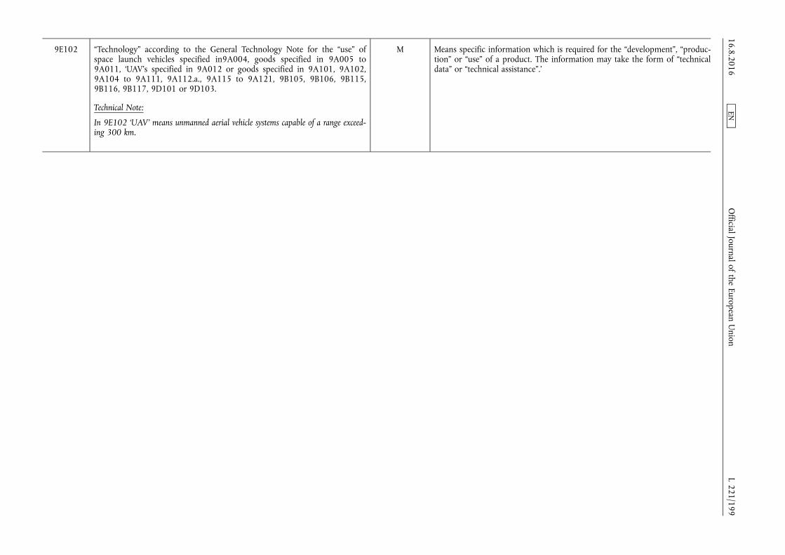
9E102 “Technology” according to the General Technology Note for the “use” of space launch vehicles specified in9A004, goods specified in 9A005 to 9A011, ‘UAV’s specified in 9A012 or goods specified in 9A101, 9A102, 9A104 to 9A111, 9A112.a., 9A115 to 9A121, 9B105, 9B106, 9B115, 9B116, 9B117, 9D101 or 9D103.
Technical Note:
In 9E102 ‘UAV’ means unmanned aerial vehicle systems capable of a range exceeding 300 km.
M Means specific information which is required for the “development”, “production” or “use” of a product. The information may take the form of “technical data” or “technical assistance”.’
16.8.2016 L 221/199
Official Journal of the European U
nion EN
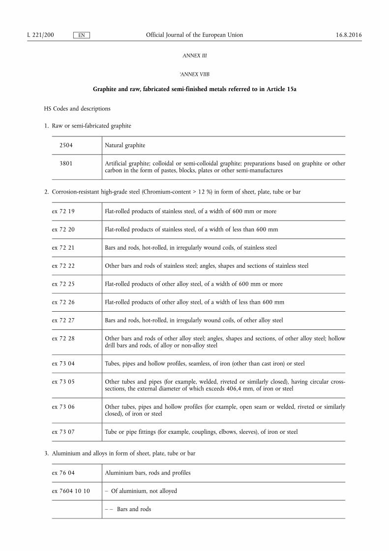
ANNEX III
‘ANNEX VIIB
Graphite and raw, fabricated semi-finished metals referred to in Article 15a
HS Codes and descriptions
1. Raw or semi-fabricated graphite
2504 Natural graphite
3801 Artificial graphite; colloidal or semi-colloidal graphite; preparations based on graphite or other carbon in the form of pastes, blocks, plates or other semi-manufactures
2. Corrosion-resistant high-grade steel (Chromium-content > 12 %) in form of sheet, plate, tube or bar
ex 72 19 Flat-rolled products of stainless steel, of a width of 600 mm or more
ex 72 20 Flat-rolled products of stainless steel, of a width of less than 600 mm
ex 72 21 Bars and rods, hot-rolled, in irregularly wound coils, of stainless steel
ex 72 22 Other bars and rods of stainless steel; angles, shapes and sections of stainless steel
ex 72 25 Flat-rolled products of other alloy steel, of a width of 600 mm or more
ex 72 26 Flat-rolled products of other alloy steel, of a width of less than 600 mm
ex 72 27 Bars and rods, hot-rolled, in irregularly wound coils, of other alloy steel
ex 72 28 Other bars and rods of other alloy steel; angles, shapes and sections, of other alloy steel; hollow drill bars and rods, of alloy or non-alloy steel
ex 73 04 Tubes, pipes and hollow profiles, seamless, of iron (other than cast iron) or steel
ex 73 05 Other tubes and pipes (for example, welded, riveted or similarly closed), having circular cross- sections, the external diameter of which exceeds 406,4 mm, of iron or steel
ex 73 06 Other tubes, pipes and hollow profiles (for example, open seam or welded, riveted or similarly closed), of iron or steel
ex 73 07 Tube or pipe fittings (for example, couplings, elbows, sleeves), of iron or steel
3. Aluminium and alloys in form of sheet, plate, tube or bar
ex 76 04 Aluminium bars, rods and profiles
ex 7604 10 10 – Of aluminium, not alloyed
– – Bars and rods
16.8.2016 L 221/200 Official Journal of the European Union EN

ex 7604 29 10 – Of aluminium alloys
– – Hollow profiles
– – – Bars and rods
7606 Aluminium plates, sheets and strip, of a thickness exceeding 0,2 mm
7608 Aluminium tubes and pipes
7609 Aluminium tube or pipe fittings (for example, couplings, elbows, sleeves)
4. Titanium and alloys in form of sheet, plate, tube or bar
ex 8108 90 Titanium and articles thereof, including waste and scrap
– Other
5. Nickel and alloys in form of sheet, plate, tube or bar
ex 75 05 Nickel bars, rods, profiles and wire
ex 7505 11 Bar and Rods
ex 7505 12
7506 Nickel plates, sheets, strip and foil
ex 75 07 Nickel tubes, pipes and tube or pipe fittings (for example, couplings, elbows, sleeves)
7507 11 – Tubes and pipes
– – Of nickel, not alloyed
7507 12 – Tubes and pipes
– – Of nickel alloys
7507 20 – Tube or pipe fittings
Explanatory note: the metal alloys in points 2, 3, 4 and 5 are those containing a higher percentage by weight of the stated metal than of any other element.’
16.8.2016 L 221/201 Official Journal of the European Union EN
Related Documents