Faculty of Engineering r NEA2 EA34 5NIVE23I4Y Department of Electrical and Electronic Engineering MO4O2 CON42OL Graduation Project EE-400 3tudent:HALİL 4IMBIL (990085) 3upervisor: Özgür Cemal Özerdem Lefkoşa - 2005

Welcome message from author
This document is posted to help you gain knowledge. Please leave a comment to let me know what you think about it! Share it to your friends and learn new things together.
Transcript
Faculty of Engineeringr
NEAR EAST UNIVERSITY
Department of Electrical and ElectronicEngineering
MOTOR CONTROL
Graduation ProjectEE-400
Student:HALİL TIMBIL (990085)
Supervisor: Özgür Cemal Özerdem
Lefkoşa - 2005

ACKNOWLEDGEMENTS
I want to thank Özgür Cemal Özerdem to be my Supervisor. I successfully overcomemany difficulties and learn a lot about electronics and control systems. He always helps me
a lot either in my study or my life. I asked him many question in Electronics and Controlsystem, and he always answered my questions quickly and detail.
Special thanks to Mr Ümit Özyürekliler with their kind help about motor control,motor repair and so on.
I also want to thank to thank my friends in NEU: Serhat,Ramazan and Serkan. Beingwith them make my 5 years in NEU full of fun.
Finaly, I want to thank my family. Without their endless support and love for me, I
would never achive my current position. I wish my mother and my father lives happilyalways.
ABSTRACT
Today's civilized word depends more heavily than ever on one of the most efficientand most important devices ever invented the electric motor. Without it, the wheels ofindustry would grind to a halt, and millions of time and labor-saving devices would berendered useless. No day passes without the discovery of new ways to use and control thisprime motive force.
Equally important is the device which drives the electric motor-the generator. Fromthe smallest stand-by unit to the largest hydroelectric plant, the demands of today's worldfor light and power are answered.
There will always be a continually increasing demand for technicians knowledgeablein these important and still growing fields.
The electric motor is a simple device in principle. It converts electric energy intomechanical energy. Over the years, electric motors have changed substantially in design,however the basic principles have remained the same.
And we have a problem how we can control motor when it starting , running orstopping. We have many solution about motor controlling. When starting we can reducevoltage for big motors. When running we can protected our motors and system byoverload relay and circuit breakers.
11
TABLE OF CONTENTS
ACKNOWLEDGMENT
ABSTRACT il
Chapter IBasic Motor Theory
1.1 Introduction1.2 Magnetism1.3 Magnetic Propulsion Within A Motor1.4 AC Current
11134
Chapter IIMotors
2.1. Main Part The Motor2.1.1 Rotor2.1.2 Stator2.1.3 The End plates (End Shields or Brackets)
2.2. AC Motors2.2.1.Single Phase Induction Motors2.2.2Shaded Pole Motors2.2.3Resistance Split-Phase Motors2.2.4.Capacitor Motors2.2.5Universal Motors2.2.6Permanent Magnet AC Motors2.2.7Stepping Motors2.2.8Repulsion-Type Motor
2.2.8.1 Construction2.3. Three-Phase Motors
2.3.1. Construction of Three-Phase Motor2.3.2. Basic Three phase AC Motor Operation
2.4. Losses And Efficiency2.4.1. Friction and Windage2.4.2. Armature Copper Losses2.4.3. Field Copper Losses2.4.4. Core Losses
2.5. Efficiency
55555678891011121515171818232324242424
Chapter IIIRewinding the Three-Phase Motor
3.1 Taking data3.2 Stripping the Winding3.3 Insulating the Stator3.4 Winding the Coils3.5 Placing Coils Iıi slots3.6 Connection the Three-phase Motor3.7 Troubleshooting
25 252526 27 27 2828
Chapter IVAlternating-current motor control
4.1.1 Contactors4.1.2 Overload Relays4.1.3 Time Relays4.1.4 Pushbutton Stations
4.2 Starters4.2.1 Dol starter4.2.2 Full-Voltage Reversing Starter4.2.3 Wye Delta Starter
, 4.2.4 AutotransformerStarter4.2.5 Resistance Starter
29 29 29 30 30 313132343638
Chapter VProject
5.1 Operation of circuit4040
.........................................................................................................................................CONCLUSION 42
REFERENCES 43
LISTS OF FIGURE
Figure 1.1 - The lines of flux of a magnetic field travelfrom the N-pole to the S-pole. 1
Figure 1.2 - The flow of electrical current in a conductor sets upconcentric lines of magnetic flux around the conductor. 2
Figure 1.3 - The magnetic. lines around a current carrying conductorleave from the N-pole and re-enter at the S-pole 2
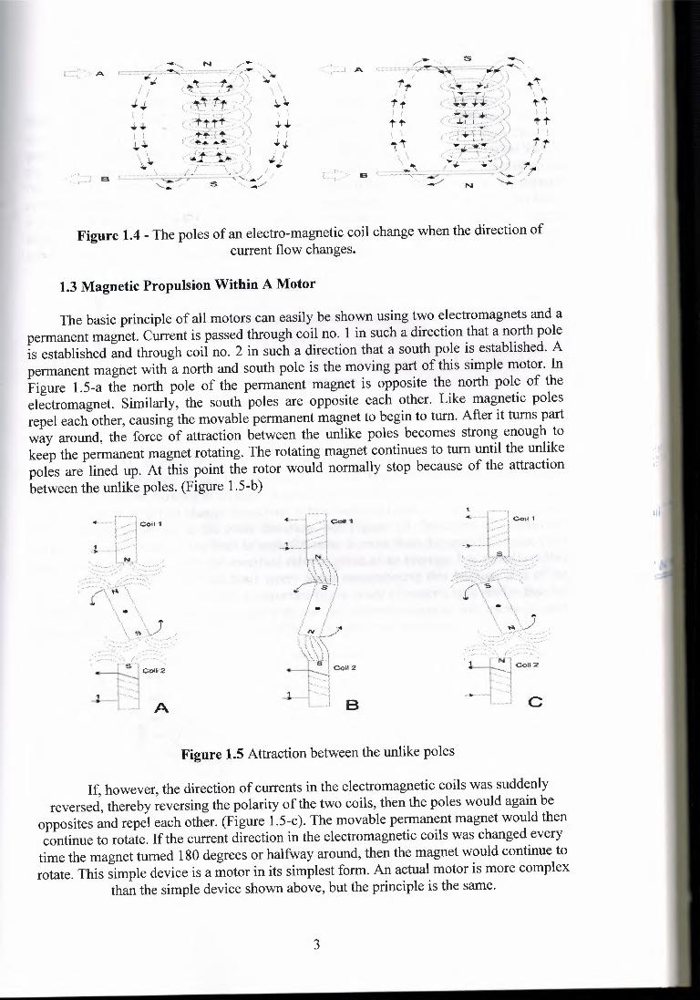
Figure 1.4 - The poles of an electro-magnetic coil change whenthe direction of current flow changes. 3
Figure 1.5 Attraction between the unlike poles 3Figure 1.6 - Visualization of DC 4Figure 1.7 - Visualization of AC.Figure 2.1 A photograph of the stator is reproduced 4Figure 2.2 A shaded pole motor with tapered poles and magnetic wedges 6Figure 2.3 Connections of a resistive, split-phase motor 8Figure 2.4 Connections of a capacitor start motor 9Figure 2.5 Connections of a capacitor-start, capacitor-run motor 1 OFigure 2.6 Connections of a permanent split capacitor motor 1 OFigure 2.7 Connections of a universal motor 11Figure 2.8 Surface mounted magnets on a Permanent Magnet AC motor 11Figure 2.9 Inset (interior) magnets on Permanent Magnet AC motor 11Figure 2.lOPermanent magnet AC motor and inverter 12Figure 2.11 Cross-sectional view of a four-phase variable reluctance motor
Number of rotor teeth 50, step number 13Figure 2.12 Steps in the operation of a permanent magnet stepping motor 14Figure 2.13 Construction of a hybrid stepping motor 14Figure 2.14 Repulsion-type motor stator 15Figure 2.15 Repulsion-type motor rotor 16Figure 2.16 Three phase motor 18Figure 2.17 Basic electrical components of an AC motor 19Figure 2.18 The rotating magnetic field of an AC motor 20Figure 2.19 The pattern of the separate phases of three-phase power 21Figure 2.20 Method of connecting three-phase power to a six-pole stator 21Figure 2.21 How three-phase power produces a rotating magnetic field 22Figure 2.22 Construction of an AC induction motor's rotor 23Figure 2.23 How voltage is induced in the rotor, resulting
in current flow in the rotor conductors. 23Figure 3.1 Open slots 26Figure 3.2 Closed slots 26
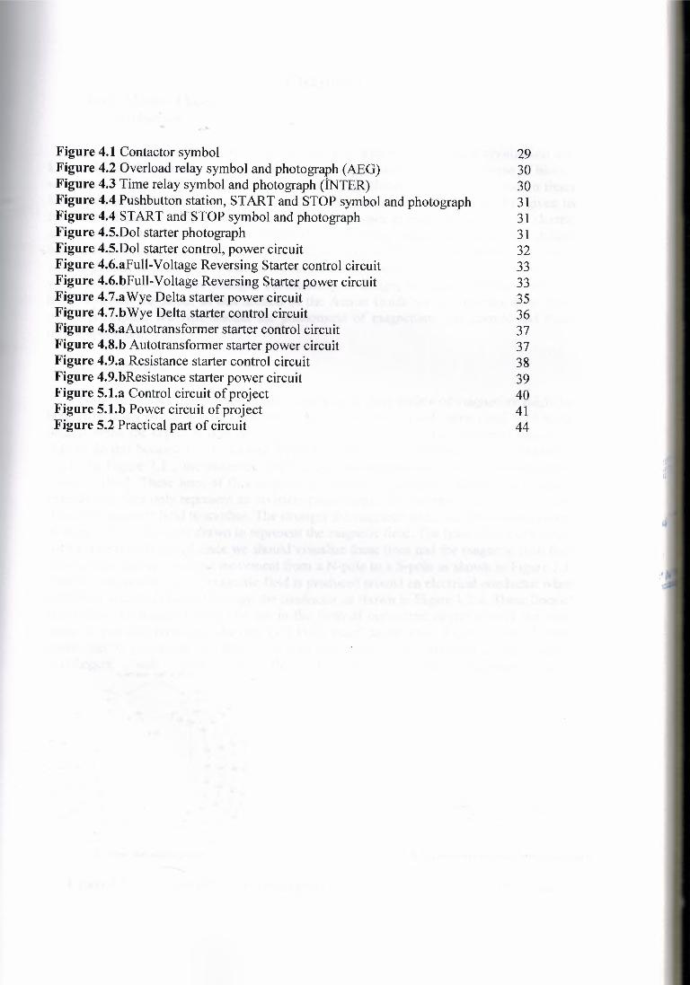
Figure 4.1 Contactor symbol 29Figure 4.2 Overload relay symbol and photograph (AEG) 30Figure 4.3 Time relay symbol and photograph (İNTER) 30Figure 4.4 Pushbutton station, START and STOP symbol and photograph 31Figure 4.4 STARTand''STOPsymbol and photograph 31Figure 4.5.Dol starterphotograph 31Figure 4.5.Dol starter control,power circuit 32Figure 4.6.aFull-VoltageReversing Starter control circuit 33Figure 4.6.bFull-VoltageReversing Starterpower circuit 33Figure 4. 7.aWyeDelta starterpower circuit 35Figure 4.7.bWye Delta starter control circuit 36Figure 4.8.aAutotransformerstarter control circuit 37Figure 4.8.b Autotransformerstarter power circuit 37Figure 4.9.a Resistance starter control circuit 38Figure 4.9.bResistance starterpower circuit 39Figure 5.1.a Control circuit of project 40Figure 5.1.b Power circuit of project 41Figure 5.2 Practical part of circuit 44
Chapter I Basic Motor Theory 1.1 Introduction
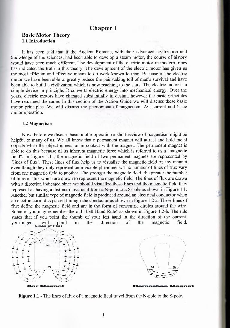
It has been said that if the Ancient Romans, with their advanced civilization andknowledge of the sciences, had been able to develop a steam motor, the course of historywould have been much different. The development of the electric motor in modern timeshas indicated the truth inthis theory. The development of the electric motor has given usthe most efficient and effective means to do work known to man. Because of the electricmotor we have been able to greatly reduce the painstaking toil of man's survival and havebeen able to build a civilization which is now reaching to the stars. The electric motor is asimple device in principle. It converts electric energy into mechanical energy. Over theyears, electric motors have changed substantially in design, however the basic principleshave remained the same. In this section of the Action Guide we will discuss these basicmotor principles. We will discuss the phenomena of magnetism, AC current and basicmotor operation.
1.2 Magnetism
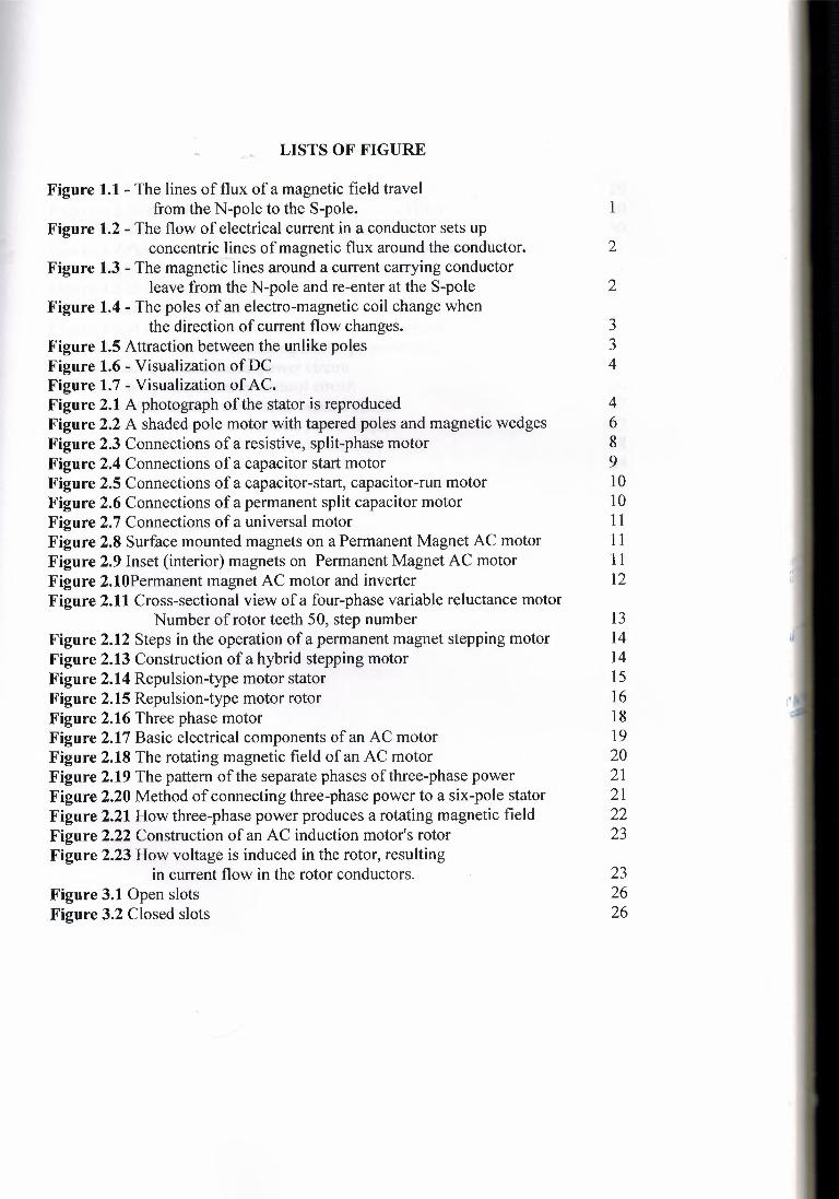
Now, before we discuss basic motor operation a short review of magnetism might behelpful to many of us. We all know that a permanent magnet will attract and hold metalobjects when the object is near or in contact with the magnet. The permanent magnet isable to do this because of its inherent magnetic force which is referred to as a "magneticfield". In Figure 1. 1 , the magnetic field of two permanent magnets are represented by"lines of flux". These lines of flux help us to visualize the magnetic field of any magneteven though they only represent an invisible phenomena. The number of lines of flux varyfrom one magnetic field to another. The stronger the magnetic field, the greater the numberof lines of flux which are drawn to represent the magnetic field. The lines of flux are drawnwith a direction indicated since we should visualize these lines and the magnetic field theyrepresent as having a distinct movement from a N-pole to a S-pole as shown in Figure 1.1.Another but similar type of magnetic field is produced around an electrical conductor whenan electric current is passed through the conductor as shown in Figure 1 .2-a. These lines offlux define the magnetic field and are in the form of concentric circles around the wire.Some of you may remember the old "Left Hand Rule" as shown in Figure 1 .2-b. The rulestates that if you point the thumb of your left hand in the direction of the current,yourfingers will point in the direction of the magnetic field.
Lines- .c::ıf Fl.u:x
Figure 1.1 - The lines of flux of a magnetic field travel from the N-pole to the S-pole.
1
tC ..:::~e··· . \'·.,]:,..... ···••••••··-·""'w .·.··"-~""""·"==·.yı ,;/
Ü /'. . .·. /.!'
Cumırtt
ı ••. ,/"ı1 I ıiı,, . .I ••l i ;' ... . (
ı ! ij .! J.l i I
i 1 ~\ ) !;.\ \ \
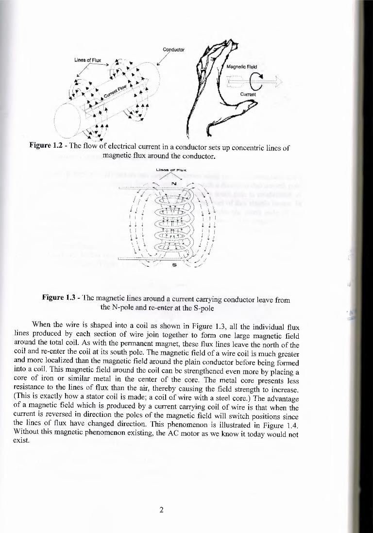
Figure 1.3 - The magnetic lines around a current carrying conductor leave fromthe N-pole and re-enter at the S-pole
When the wire is shaped into a coil as shown in Figure 1.3, all the individual fluxlines produced by each section of wire join together to form one large magnetic fieldaround the total coil. As with the permanent magnet, these flux lines leave the north of thecoil and re-enter the coil at its south pole. The magnetic field of a wire coil is much greaterand more localized than the magnetic field around the plain conductor before being formedinto a coil. This magnetic field around the coil can be strengthened even more by placing acore of iron or similar metal in the center of the core. The metal core presents lessresistance to the lines of flux than the air, thereby causing the field strength to increase.(This is exactly how a stator coil is made; a coil of wire with a steel core.) The advantageof a magnetic field which is produced by a current carrying coil of wire is that when thecurrent is reversed in direction the poles of the magnetic field will switch positions sincethe lines of flux have changed direction. This phenomenon is illustrated in Figure 1 .4.Without this magnetic phenomenon existing, the AC motor as we know it today would notexist.
2
Jj, I I,,ı..;,.
I I,,ı,..ı...\ \' ,,
J..""'
•+ı iI ~....
) }
,t :...
.•./1"
~/,, f'J ''t 1"'!. I,.,..
) \\ C
..~\ \
t'tI't t
A A
ı ltt
/ j_/.•i ,.
,,'
N
Figure 1.4 - The poles of an electro-magnetic coil change when the direction ofcurrent flow changes.
1.3 Magnetic Propulsion Within A Motor
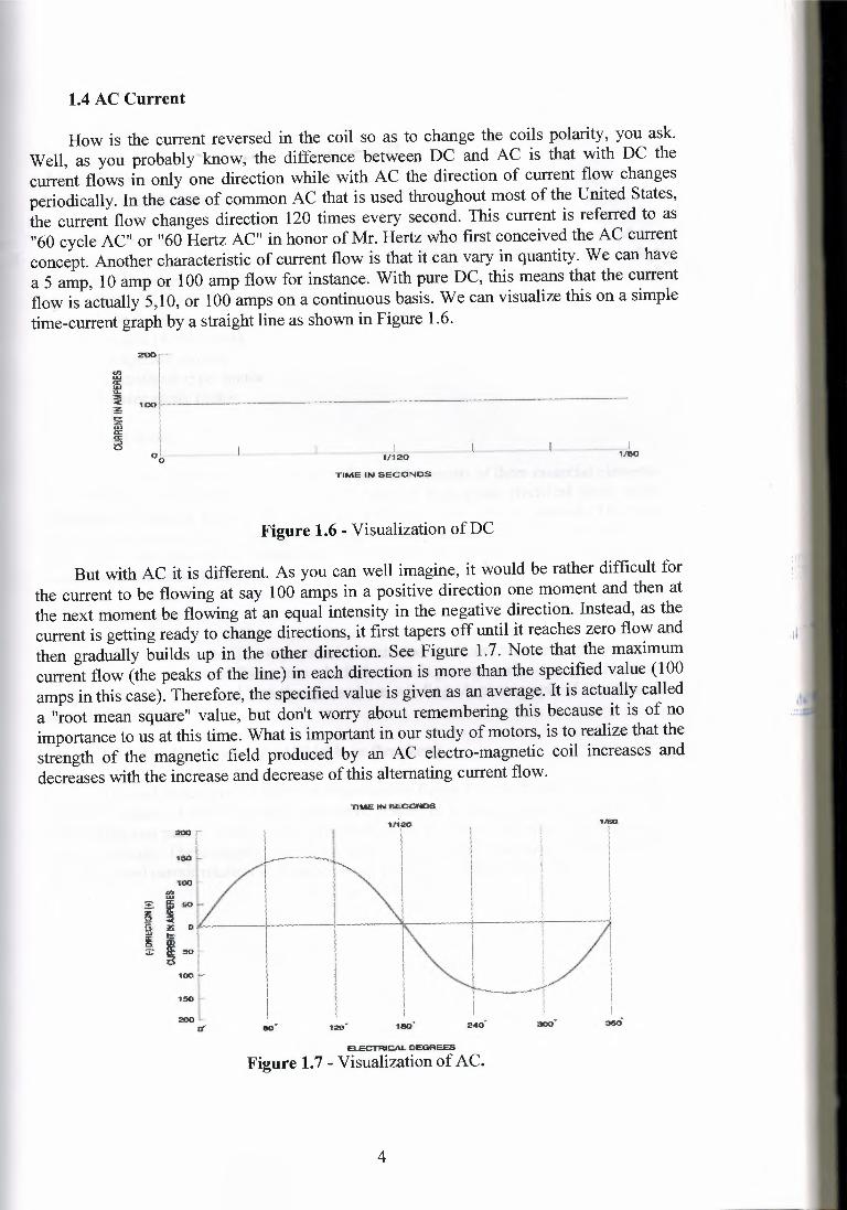
The basic principle of all motors can easily be shown using two electromagnets and apermanent magnet. Current is passed through coil no. 1 in such a direction that a north poleis established and through coil no. 2 in such a direction that a south pole is established. Apermanent magiıet with a north and south pole is the moving part of this simple motor. InFigure 1.5-a the north pole of the permanent magnet is opposite the north pole of theelectromagnet. Similarly, the south poles are opposite each other. Like magnetic polesrepel each other, causing the movable permanent magnet to begin to turn. After it turns partway around, the force of attraction between the unlike poles becomes strong enough tokeep the permanent magnet rotating. The rotating magnet continues to tum until the unlikepoles are lined up. At this point the rotor would normally stop because of the attractionbetween the unlike poles. (Figure 1.5-b)
Figure 1.5 Attraction between the unlike poles
If, however, the direction of currents in the electromagnetic coils was suddenlyreversed, thereby reversing the polarity of the two coils, then the poles would again be
opposites and repel each other. (Figure 1 .5-c). The movable permanent magnet would thencontinue to rotate. If the current direction in the electromagnetic coils was changed every
time the magnet turned 180 degrees or halfway around, then the magnet would continue torotate. This simple device is a motor in its simplest form. An actual motor is more complex
than the simple device shown above, but the principle is the same.
3
1.4 AC Current
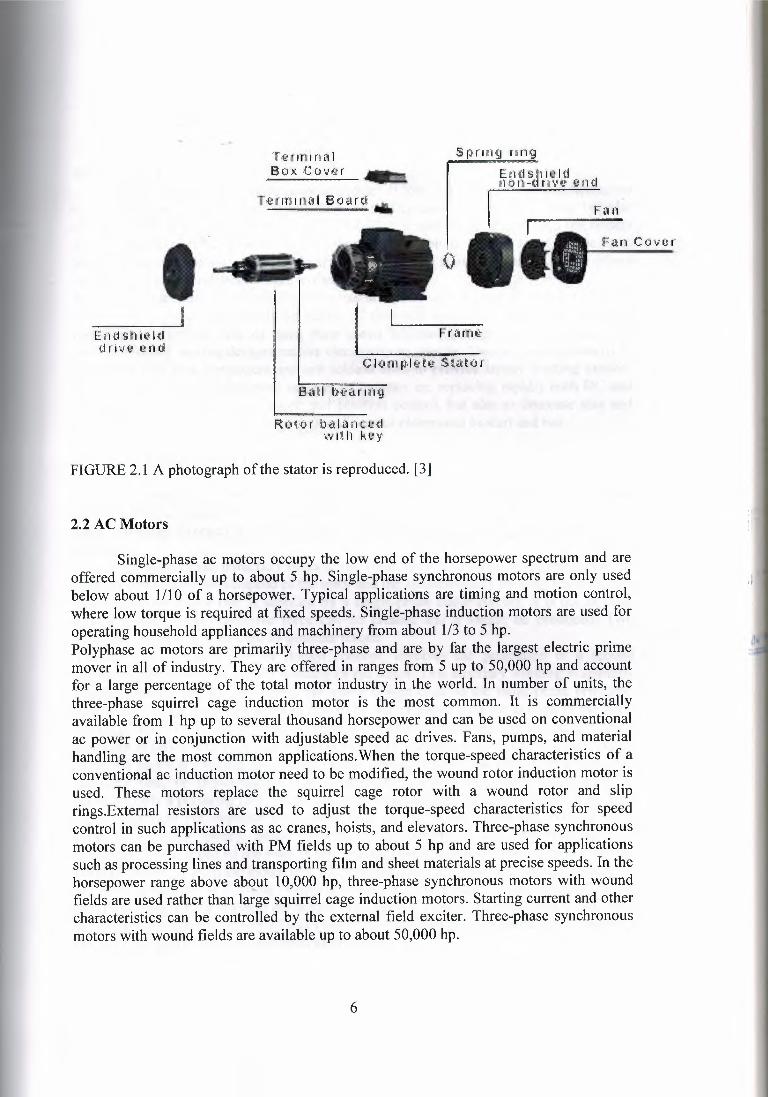
How is the current reversed in the coil so as to change the coils polarity, you ask.Well, as you probably know, ·the difference between DC and AC is that with DC thecurrent flows in only one direction while with AC the direction of current flow changesperiodically. In the case of common AC that is used throughout most of the United States,the current flow changes direction 120 times every second. This current is referred to as"60 cycle AC" or "60 Hertz AC" in honor of Mr. Hertz who first conceived the AC currentconcept. Another characteristic of current flow is that it can vary in quantity. We can havea 5 amp, 1 O amp or 100 amp flow for instance. With pure DC, this means that the currentflow is actually 5,10, or 100 amps on a continuous basis. We can visualize this on a simpletime-current graph by a straight line as shown in Figure 1 .6.
TIME ,ı:,_. SECONDS
Figure 1.6 - Visualization of DC
But with AC it is different. As you can well imagine, it would be rather difficult forthe current to be flowing at say 100 amps in a positive direction one moment and then atthe next moment be flowing at an equal intensity in the negative direction. Instead, as thecurrent is getting ready to change directions, it first tapers off until it reaches zero flow andthen gradually builds up in the other direction. See Figure 1.7. Note that the maximumcurrent flow (the peaks of the line) in each direction is more than the specified value (100amps in this case). Therefore, the specified value is given as an average. It is actually calleda "root mean square" value, but don't worry about remembering this because it is of noimportance to us at this time. What is important in our study of motors, is to realize that thestrength of the magnetic field produced by an AC electro-magnetic coil increases anddecreases with the increase and decrease of this alternating current flow.
'tlM'2'1N~
1t1iI
·-..,. I"- I
' I' !'\ .. '
,:aıo uııı·
ELECTRICAL DEGREES
Figure 1.7 - Visualization of AC.
4
Chapter IIMOTORS
2.1 Main Part The Motor
Motor is a device which coverts electrical energy to mechanical energy. Motorhas three main part. These are (1) a rotating part, called rotor; (2) a stationary part, calledthe stator; (3) end plate, or brackets, which fastened to the frame of the stator by means ofscrews blots. AC Motors are many type.
1 Single phase motora split phase motors
bcapacitor motorsc repulsion-type motor
2 Three phase motor
2.1.1 Rotor
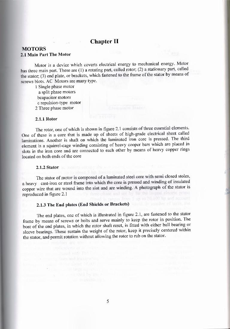
The rotor, one of which is shown in figure 2. 1 consists of three essential elements.One of these is a core that is made up of sheets of high-grade electrical sheet calledlaminations. Another is shaft on which the laminated iron core is pressed. The thirdelement is a squirrel-cage winding consisting of heavy cooper bars which are placed inslots in the iron core and are connected to each other by means of heavy copper ringslocated on both ends of the core
2.1.2 Stator
The stator of motor is composed of a laminated steel core with semi closed stoles,a heavy cast-iron or steel frame into which the core is pressed and winding of insulatedcopper wire that are wound into the slot and are winding. A photograph of the stator isreproduced in figure 2.1
2.1.3 The End plates (End Shields or Brackets)
The end plates, one of which is illustrated in figure 2. 1, are fastened to the statorframe by means of screws or bolts and serve mainly to keep the rotor in position. Thebore of the end plates, in which the rotor shaft reset, is fitted with either ball bearing orsleeve bearings. These sustain the weight of the rotor, keep it precisely centered withinthe stator, and permit rotation without allowing the rotor to rub on the stator.
5
ıl
TennırıaıBox c ever
s r1rırıg rıngE:ııdslı le,ıdIi O rtı-GH ı •,t;ı, ı;ı fl d
F\ı n
I'•••••• ••
·--" l ..·ı··ı,' .·.. ,.·.:._ı', \ ~
', '
l::ndsııield· ttriv't: eıHi
R:ut0hr ı:ıaı..-fr,i:c<tvvilıh k.ey
FIGURE 2.1 A photograph of the stator is reproduced. [3]
2.2 AC Motors"•t
Single-phase ac motors occupy the low end of the horsepower spectrum and areoffered commercially up to about 5 hp. Single-phase synchronous motors are only usedbelow about 1/10 of a horsepower. Typical applications are timing and motion control,where low torque is required at fixed speeds. Single-phase induction motors are used foroperating household appliances and machinery from about 1/3 to 5 hp.Polyphase ac motors are primarily three-phase and are by far the largest electric primemover in all of industry. They are offered in ranges from 5 up to 50,000 hp and accountfor a large percentage of the total motor industry in the world. In number of units, thethree-phase squirrel cage induction motor is the most common. It is commerciallyavailable from 1 hp up to several thousand horsepower and can be used on conventionalac power or in conjunction with adjustable speed ac drives. Fans, pumps, and materialhandling are the most common applications. When the torque-speed characteristics of aconventional ac induction motor need to be modified, the wound rotor induction motor isused. These motors replace the squirrel cage rotor with a wound rotor and sliprings.External resistors are used to adjust the torque-speed characteristics for speedcontrol in such applications as ac cranes, hoists, and elevators. Three-phase synchronousmotors can be purchased with PM fields up to about 5 hp and are used for applicationssuch as processing lines and transporting film and sheet materials at precise speeds. In thehorsepower range above about 10,000 hp, three-phase synchronous motors with woundfields are used rather than large squirrel cage induction motors. Starting current and othercharacteristics can be controlled by the external field exciter. Three-phase synchronousmotors with wound fields are available up to about 50,000 hp.
ıl
6
IntroductionSmall electrical machines carry a substantial load in residential environments, but
also in industrial environments,where they are mostly used to control processes. In orderto adapt to the limitations of the power available, the cost requirements, and the widelyvarying operating requirements, small motors are available in a great variety of designs.Some of the small motors require electronics in order to start and operate, while otherscan start and run directly connectedto the supply line.AC motors that can start directly from the line are mostly of the inductiontype. Universalmotors are also used extensively for small AC powered, handheld tools. They can eitherrun directly from the line or have their speed adjusted through electronics.Steppingmotors of many varying designs require electronics to operate.They are used primarily toposition a tool or a component and are seldom used to provide steady rotating motion.Besides these motors, permanent magnet AC motors are replacing rapidly both DC andinduction motors for accurate speed and position control, but also to decrease size andincrease efficiency.They require power and control electronicsto start and run.
2.2.1 Single Phase Induction Motors
To produce rotation, a multi-phase stator winding is often used in an AC motor,supplied from a symmetric and balanced system of currents. The magnetomotive force ofthese windings interacts with the magnetic field of the rotor (induced or applied) toproduce atorque. In three-phase induction motors, the rotor field is created by currents that areinduceddue to the relative speed of the rotor and the synchronouslyrotating stator field.In an induction motor that is supplied by a single-phase stator current, it is not as clearhow a rotating magnetomotive force can be created and a torque be produced. Twodifferent conceptswill be used to generate torque.The first, conceptually simpler design concept, involves the generation of a secondcurrent which flows in a second winding of the stator. This auxiliary winding is spatiallydisplaced on the stator. This brings the motor design close to the multi-phase principle.The current in the auxiliary winding has to be out of phase with the current in the mainwinding, and this is accomplished through the use of increased resistance in it or acapacitor in serieswith it. A motor can operate in this fashionover its entire speed range.Once the motor is rotating, the second design concept allows that one of the phases, theauxiliary one, be disconnected. The current in the remaining main winding aloneproduces only a pulsating flux, which can be analyzed as the sum of two rotating fields ofequal amplitude but opposite direction. These fields, as seen from the moving rotor,rotate at different speeds, hence inducing in it currents of different frequency andamplitude. If the speed of the rotor is wr , the applied frequencyto the stator is f and thenumber of pole pairs in the motor is p, the frequencies of the currents induced in the rotorare pwr - f and pwr + f These unequal currents in tum produce unequal torques in thetwo directions, with a nonzero net torque. The various designs of single-phase inductionmotors result from the variety of ways that the two phases are generated and by whetherthe auxiliaryphase remains energizedafter starting.
7
2.2.2 Shaded Pole Motors
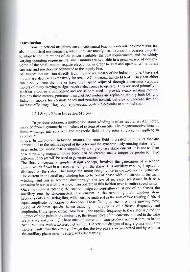
These motors are simple, reliable, and inefficient. The stator winding is notdistributed on the rotor surface, but rather it is concentrated on salient poles. Theauxiliary winding, which has to produce flux out of phase with the main winding, isnothing but a hardwiredshorted tum around a portion of the main pole as Fig. 2.2.Because of the shorted tum, the flux out of the shaded part of the pole lags behind theflux out of the main pole. The motor always rotates from the main to the shaded pole, andit is not possible to change directions. Shaded pole motors are inefficient and have highstarting and running current and low starting torque. They are used where reliability andcost are important, while their small size makes unimportant the overall effect of theirdisadvantages, e.g., small fans. Their size ranges from 0.002 to O. 1 h ---=--
FIGURE 2.2 A shaded pole motor with tapered poles and magnetic wedges.[l.ı]
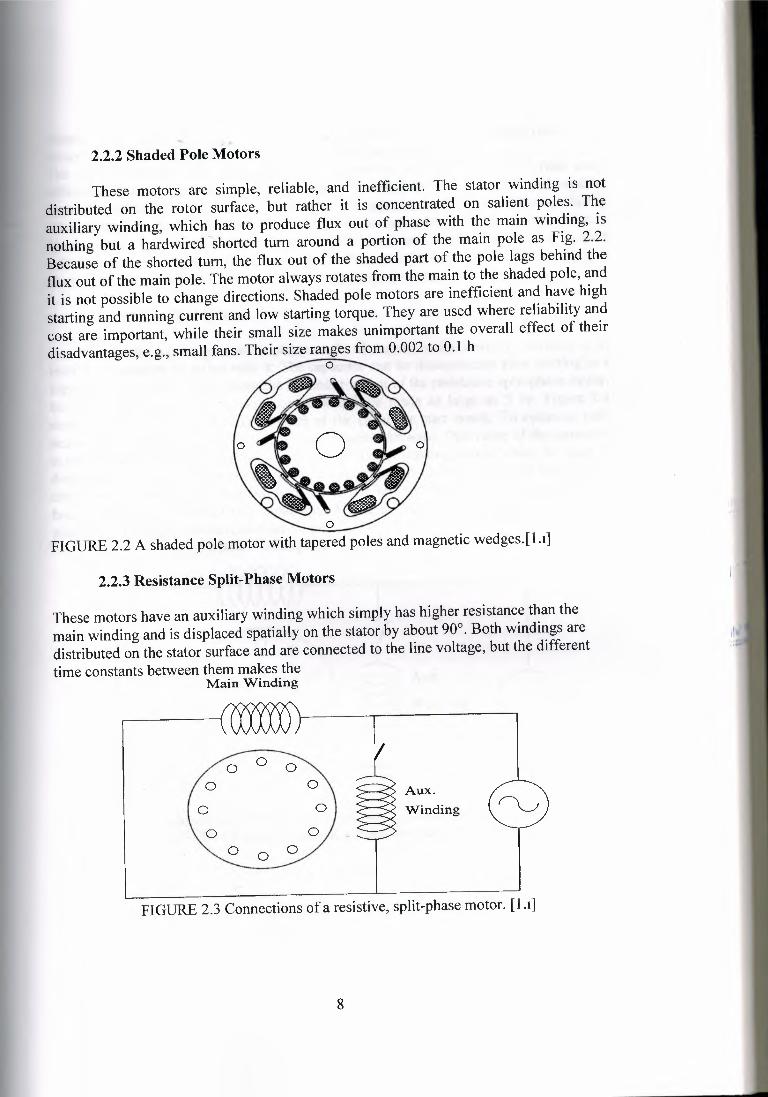
2.2.3 Resistance Split-Phase Motors
These motors have an auxiliary winding which simply has higher resistance than themain winding and is displaced spatially on the stator by about 90°. Both windings aredistributed on the stator surface and are connected to the line voltage, but the differenttime constants between them makes the
Main Winding
o o oo 00) §Aux
o Winding
o oo o o
FIGURE 2.3 Connections of a resistive, split-phase motor. [l.ı]
8
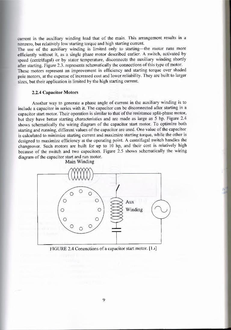
2.2.4 Capacitor Motors
current in the auxiliary winding lead that of the main. This arrangement results in anonzero, but relatively low starting torque and high starting current.The use of the auxiliary winding is limited only to starting-the motor runs moreefficiently without it, as a single phase motor described earlier. A switch, activated byspeed (centrifugal) or by stator temperature, disconnects the auxiliary winding shortlyafter starting. Figure 2.3. represents schematicallythe connectionsof this type of motor.These motors represent.an improvement in efficiency and starting torque over shadedpole motors, at the expense of increased cost and lower reliability.They are built to largersizes, but their application is limited by the high starting current.
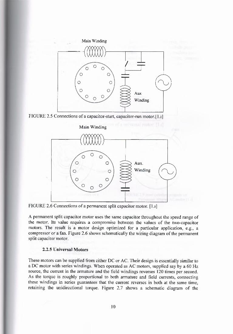
Another way to generate a phase angle of current in the auxiliary winding is toinclude a capacitor in series with it. The capacitor can be disconnected after starting in acapacitor start motor. Their operation is similar to that of the resistance split-phase motor,but they have better starting characteristics and are made as large as 5 hp. Figure 2.4shows schematically the wiring diagram of the capacitor start motor. To optimize bothstarting and running, different values of the capacitor are used. One value of the capacitoris calculated to minimize starting current and maximize starting torque, while the other isdesigned to maximize efficiency at the operating point. A centrifugal switch handles thechangeover. Such motors are built for up to 1 O hp, and their cost is relatively highbecause of the switch and two capacitors. Figure 2.5 shows schematically the wiringdiagram of the capacitor start and run motor.
Main Winding
o o oo o \ ~Aux
o o} ~ Winding
o oo o o
FIGURE 2.4 Conenctionsof a capacitor start motor. [1.ı]
9
Main Winding
o oo~ µ
oo oo o)o o ~ Aux
Winding
FIGURE 2.5 Connections of a capacitor-start, capacitor-run motor.[ l .ı]
Main Winding
o o oo O\ ::=---::) Aux.
o Ol 5-o Winding
o oo o o
FIGURE 2.6 Connections of a permanent split capacitor motor. [1.ı]
A permanent split capacitor motor uses the same capacitor throughout the speed range ofthe motor. Its value requires a compromise between the values of the two-capacitormotors. The result is a motor design optimized for a particular application, e.g., acompressor or a fan. Figure 2.6 shows schematically the wiring diagram of the permanentsplit capacitor motor.
2.2.5 V niversal Motors
These motors can be supplied from either DC or AC. Their design is essentially similar toa DC motor with series windings. When operated as AC motors, supplied say by a 60 Hzsource, the current in the armature and the field windings reverses 120 times per second.As the torque is roughly proportional to both armature and field currents, connectingthese windings in series guarantees that the current reverses in both at the same time,retaining the unidirectional torque. Figure 2. 7 shows a schematic diagram of the
10
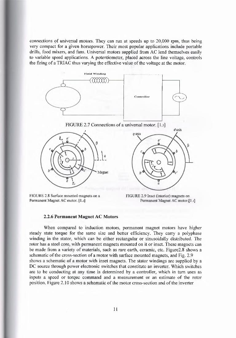
connections (2f universal motors. They can run at speeds up to 20,000 rpm, thus beingvery compact for a given horsepower. Their most popular applications include portabledrills, food mixers, and fans. Universal motors supplied from AC lend themselves easilyto variable speed applications. A potentiometer, placed across the line voltage, controlsthe firing of a TRIAC thus varying the effective value of the voltage at the motor.
Field Winding
Controller
FIGURE 2.7 Connectionsof a universal motor. [ l.ı]
FIGURE 2.8 Surface mounted magnets on aPermanent Magnet AC motor. [1.ı]
FIGURE 2.9 Inset (interior) magnets onPermanent Magnet AC motor.[1.ı]
2.2.6 Permanent Magnet AC Motors
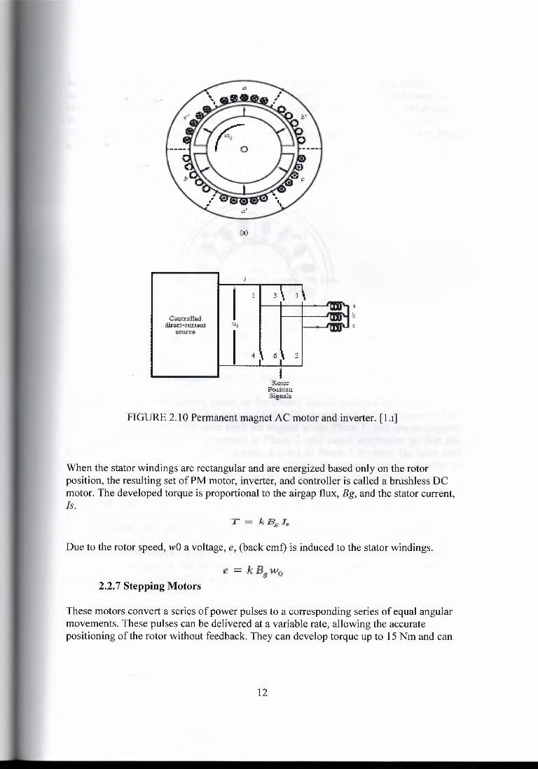
When compared to induction motors, permanent magnet motors have highersteady state torque for the same size and better efficiency. They carry a polyphasewinding in the stator, which can be either rectangular or sinusoidally distributed. Therotor has a steel core, with permanent magnets mounted on it or inset. These magnets canbe made from a variety of materials, such as rare earth, ceramic, etc. Figure2.8 shows aschematicof the cross-sectionof a motor with surface mounted magnets, and Fig. 2.9shows a schematic of a motor with inset magnets. The stator windings are supplied by aDC source through power electronic switches that constitute an inverter. Which switchesare to be conducting at any time is determined by a controller, which in tum uses asinputs a speed or torque command and a measurement or an estimate of the rotorposition. Figure 2.10 shows a schematic of the motor cross-section and of the inverter
11
Crurtro:Uwtdir~ı:t-,zw:nınt I ''il!
ı.cun:ı;,
:15'.of;..">a":ı::ıo,.iıicaSigı:ızl;
FIGURE 2.10 Permanent magnet AC motor and inverter. [l.ı]
When the stator windings are rectangular and are energized based only on the rotorposition, the resulting set of PM motor, inverter, and controller is called a brushless DCmotor. The developed torque is proportional to the airgap flux, Bg, and the stator current,ls.
Due to the rotor speed, wO a voltage, e, (back emf) is induced to the stator windings.
2.2.7 Stepping Motors
These motors convert a series of power pulses to a corresponding series of equal angularmovements. These pulses can be delivered at a variable rate, allowing the accuratepositioning of the rotor without feedback. They can develop torque up to 15 Nm and can
12
handle 1500 to 2500 pulses per second. They have zero steady state error in positioningand high torque density. An important characteristic of stepping motors is that when onephase is activated they do not develop a rotating but rather a holding torque, which makesthem retain accurately their position, even under load.Stepping motors are conceptually derived either from a variable reluctance motor or froma permanentmagnet synchronous motor.
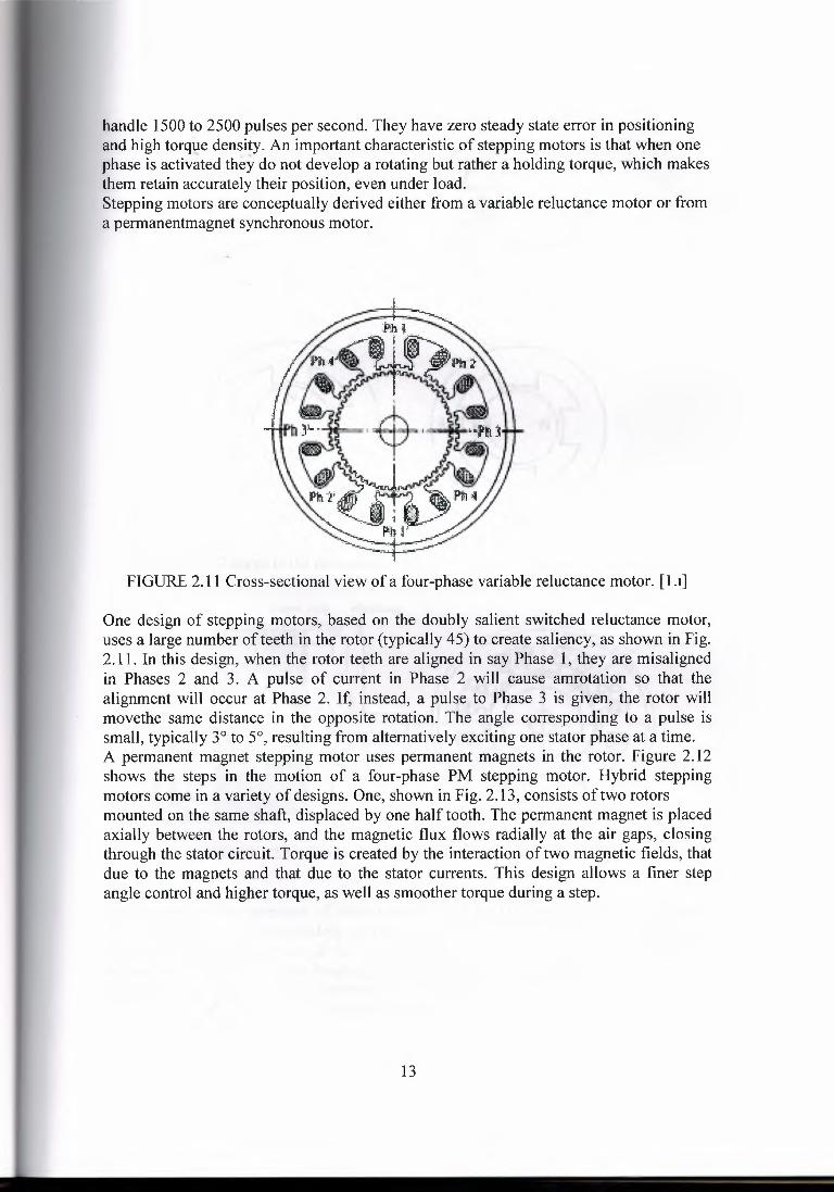
FIGURE 2.11 Cross-sectional view of a four-phase variable reluctance motor. [1 .ı]
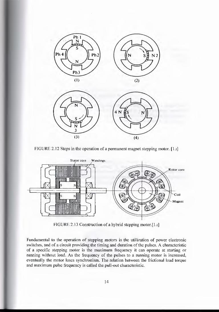
One design of stepping motors, based on the doubly salient switched reluctance motor,uses a large number of teeth in the rotor (typically 45) to create saliency, as shown in Fig.2.11. In this design, when the rotor teeth are aligned in say Phase 1, they are misalignedin Phases 2 and 3. A pulse of current in Phase 2 will cause amrotation so that thealignment will occur at Phase 2. If, instead, a pulse to Phase 3 is given, the rotor willmovethe same distance in the opposite rotation. The angle corresponding to a pulse issmall, typically 3° to 5°, resulting from alternatively exciting one stator phase at a time.A permanent magnet stepping motor uses permanent magnets in the rotor. Figure 2.12shows the steps in the motion of a four-phase PM stepping motor. Hybrid steppingmotors come in a variety of designs. One, shown in Fig. 2.13, consists of two rotorsmounted on the same shaft, displaced by one half tooth. The permanent magnet is placedaxially between the rotors, and the magnetic flux flows radially at the air gaps, closingthrough the stator circuit. Torque is created by the interaction of two magnetic fields, thatdue to the magnets and that due to the stator currents. This design allows a finer stepangle control and higher torque, as well as smoother torque during a step.
13
(I)
(3)
(2)
(4)
FIGURE 2. 12 Steps in the operation of a permanent magnet stepping motor. [l .ı]
Stator core Windings
Rotor core
Coil
FIGURE 2.13 Construction of a hybrid stepping motor.[l.ı]
Fundamental to the operation of stepping motors is the utilization of power electronicswitches, and of a circuit providing the timing and duration of the pulses. A characteristicof a specific stepping motor is the maximum frequency it can operate at starting orrunning without load. As the frequency of the pulses to a running motor is increased,eventually the motor loses synchronism. The relation between the frictional load torqueand maximum pulse frequency is called the pull-out characteristic.
14
2.2.8 Repulsion-Type Motor
In general, repulsion motor may be divided into three distinct classifications. These arelthe repulsion motor, 2 the repulsion-start, induction motor, and 3 the repulsion-inductionmotor. These motors are called single-phase wound-rotor and are defined and classifiedby NEMA as follows:
Repulsion Motor: A repulsion motor is a single-phase motor which has a stator windingarranged for connection to a source of power and a rotor winding connected to acommutator. Brushes on the commutator are short-circuited and are so placed that themagnetic axis of the rotor winding is inclined to the magnetic axis of the stator winding.This type of motor has a varying-speed characteristic.
Repulsion-start Induction Motor: A repulsion-start induction motor is a single-phasemotor having the same windings as repulsion motor, but at a predetermined speed therotor winding is sort circuited or otherwise connected to give the equivalent of a squirrelcage winding. This type of motor starts as repulsion motor but operates as an inductionmotor with constant-speed characteristic.
Repulsion-induction Motor: A repulsion-induction motor is from of repulsion motorwhich has a squirrel-cage winding in the rotor in additional to the repulsion motorwinding. A rotor of this type may have either a constant-speed or varying-speedcharacteristic.
These three classes are often confused by the beginner because of the similarity of names.But each is different from the other, having its own characteristic and applications.However, one feature common to all is that each has a rotor containing a winding that isconnected to commotator. These motor generally operates from a single-phase lighting orpower circuit, depending on the size of the motor.
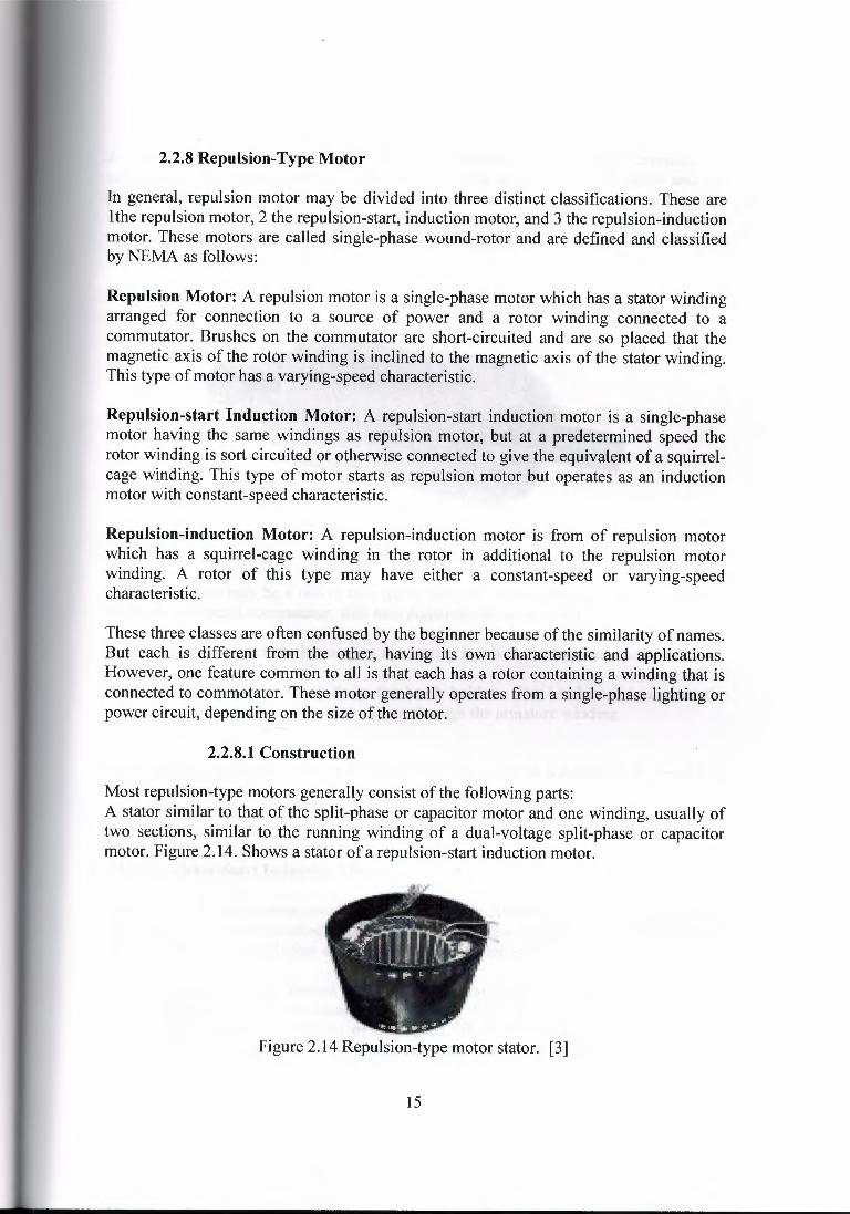
2.2.8.1 Construction
Most repulsion-type motors generally consist of the following parts:A stator similar to that of the split-phase or capacitor motor and one winding, usually oftwo sections, similar to the running winding of a dual-voltage split-phase or capacitormotor. Figure 2. 14. Shows a stator of a repulsion-start induction motor.
Figure 2.14 Repulsion-type motor stator. [3]
15
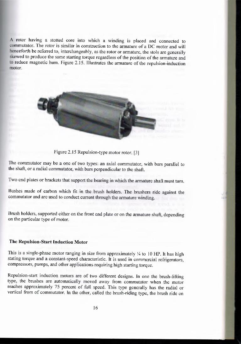
A rotor having a stotted core into which a winding is placed and connected tocommutator. The rotor is similar in construction to the armature of a DC motor and willhenceforth be referred to, interchangeably, as the rotor or armature, the stols are generallyskewed to produce the same starting torque regardless of the position of the armature andto reduce magnetic hum. Figure 2.15. Illustrates the armature of the repulsion-inductionmotor.
Figure 2.15 Repulsion-type motor rotor. [3]
The commutator may be a one of two types: an axial commutator, with bars parallel tothe shaft, or a radial commutator, with bars perpendicular to the shaft.
Two end plates or brackets that support the bearing in which the armature shaft must tum.
Bushes made of carbon which fit in the brush holders. The brushers ride against thecommutator and are used to conduct current through the armature winding.
Brush holders, supported either on the front end plate or on the armature shaft, dependingon the particular type of motor.
The Repulsion-Start Induction Motor
This is a single-phase motor ranging in size from approximately Yı to 10 HP. It has highstating torque and a constant-speed characteristic. It is used in commercial refrigerators,compressors, pumps, and other applications requiring high starting torque.
Repulsion-start induction motors are of two different designs. In one the brush-liftingtype, the brushes are automatically moved away from commutator when the motorreaches approximately 75 percent of full speed. This type generally has the radial orvertical from of commutator. In the other, called the brush-riding type, the brush ride on
16
the commutator at all times. This type has the axial from of commutator. In orderoperating principles, these motor types are identical.
The Repulsion Motor
This motor is distinguished from repulsion-start induction motor by the fact that it ismade exclusively as a brush-riding type and does not have any centrifugal mechanism.This motor both stats and runs on the repulsion principle. In common with a DC seriesmotor, it has high starting torque and a variable-speed characteristic. It is reversed byshifting the brush holder to either side of the neutral position. Its speed can be decreasedby moving the brush holder further away from the neutral position. This motor issometimescalled an induction-seriesmotor.This stator of the repulsion motor is like that of repulsion-start induction motor, and thestator poles are connected in the same manner. The stator is generally wound for four,six, or either poles. Usually four leads are brought out for dual-voltageoperation.The rotors consist of an armature constructed in the same manner as the DC type. It islaminated and generally skewed. The winding may be either hand or coil wound and isconnected either lap or wave. The commutator is the axial type and the brushes alwaysride on the commutator. The brushes are all connected together as in the repulsion-startmotor.
The Repulsion-Induction Motor J
It is sometimes impossible to tell the difference between the repulsion-induction motorand the repulsion motor and the repulsion motor by external appearance. However, therepulsion-inductionmotor has a squirrel-cagewinding on the armature in the addition tothe regular winding. The squirrel-cage winding is located underneath the slots of thearmature. The armature is usually lap-woundand cross-connected.To tell the difference between a repulsion and repulsion-induction motor, connect themotor to the line and permit it to reach full speed. Then raise all brushes so that they nolonger contact the commutator. If the motor continues to operate at full speed, it is arepulsion-induction motor. Repulsion-induction motors are made in size up to about 1 OHP. They are dual-voltage types and can be used for general-purposeduty. In the field ofrepulsion motors, this type is becoming very popular, because of their good all-roundcharacteristics,which are comparableto those of the DC compound motor.The advantage of this motor lies in the fact that no centrifugal short-circuitingmechanism is used. It has high starting torque and owing to the squirrel-cagewinding, afairly constant speed regulation. These motors are also made with compensating coils toincrease the power factor of the motor circuit.
2.3. Three-Phase Motors
Three-phase motors vary from fractional-horse power size to several thousandhorsepower. These motors have a fairly constant speed characteristic and are made indesigns giving a variety of torque characteristic. Some three-phase motors have a highstarting torque; others, a low starting torque. Some are designed to draw a normal starting
17
current. They are made for practically every standard voltage and frequency and are veryoften dual-voltage motors. Three-phase motors are used to drive machine tools, pumps,elevators, fans, cranes, hoists, blowers, and may other machines.
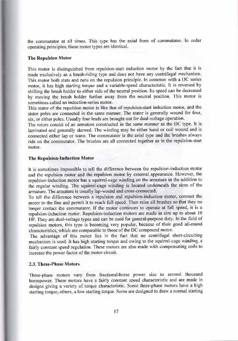
2.3.1 Construction of Three-Phase Motor
A three-phase motor is shown in figure 2. 16. It has three main parts: stator, rotor, and endplates. Its construction is similar to that of the split-phase motor, but it has no centrifugalswitch.The stator is shown in figure 2. 16. And consists of a frame and a laminated steel core likethat used in split-phase and repulsion motors and winding formed of individual coilsplaced in slots. The rotor may be die cast aluminum squirrel-cage type or a wound rotor.Both types contain a laminated core pressed onto a shaft. The squirrel-cage rotor isshown on figure 2. 16 and is like that of split-phase motor.
:!1, 'I
Figure 2. 16 Three phase motor. [3]
2.3.2 Basic Three phase AC Motor Operation An AC motor has two basic electrical parts: a "stator" and a "rotor" as shown in
Figure 2. 17. The stator is in the stationary electrical component. It consists of a group ofindividual electro-magnets arranged in such a way that they form a hollow cylinder, withone pole of each magnet facing toward the center of the group. The term, "stator" is
18
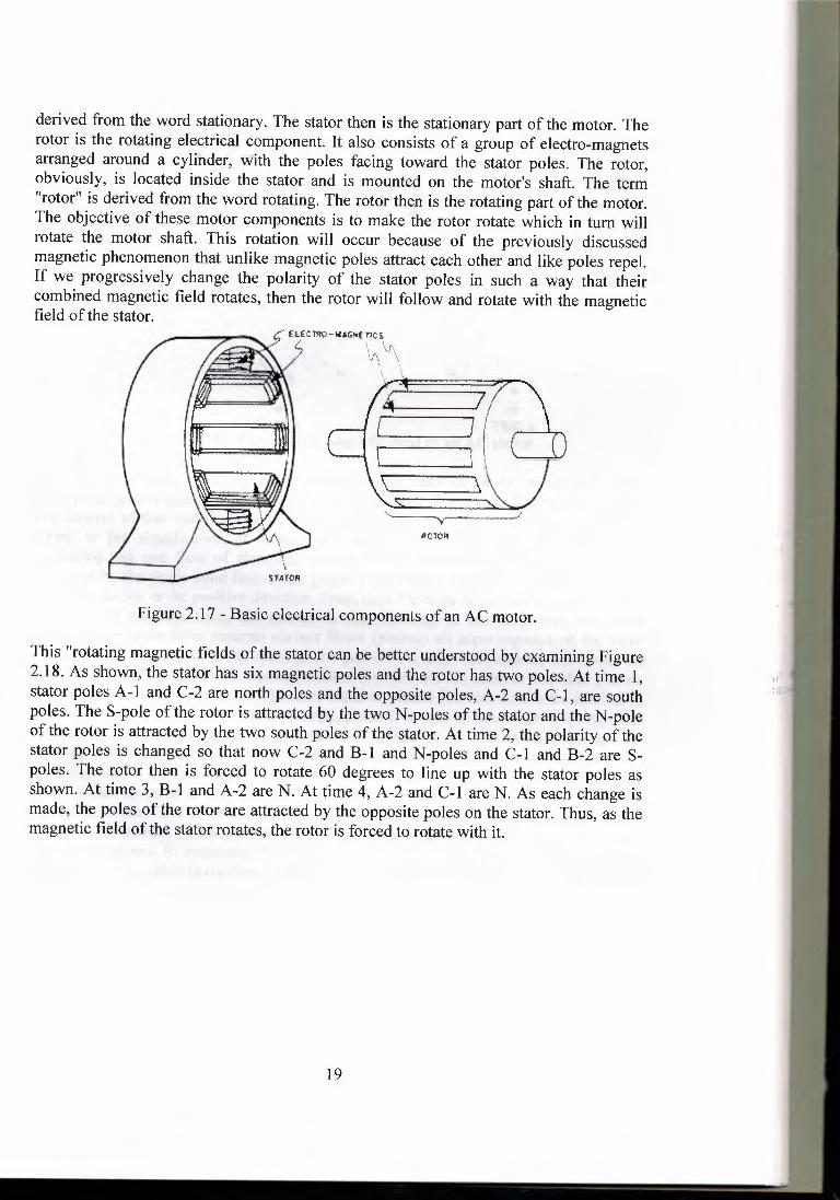
derived from the word stationary. The stator then is the stationary part of the motor. Therotor is the rotating electrical component. It also consists of a group of electro-magnetsarranged around a cylinder, with the poles facing toward the stator poles. The rotor,obviously, is located inside the stator and is mounted on the motor's shaft. The term"rotor" is derived from the word rotating. The rotor then is the rotating part of the motor.The objective of these motor components is to make the rotor rotate which in tum willrotate the motor shaft. This rotation will occur because of the previously discussedmagnetic phenomenon that unlike magnetic poles attract each other and like poles repel.If we progressively change the polarity of the stator poles in such a way that theircombined magnetic field rotates, then the rotor will follow and rotate with the magneticfield of the stator.
Ç (ı,,Hfı'ıö-,..AGk(TIC:S~· S ı 'r.-_x .. · '· \ \~, / ,_,(\ \
~ I I
I~\\ \\ \"·
.,\
~i'AfOR
Figure 2.17 - Basic electrical componentsof an AC motor.
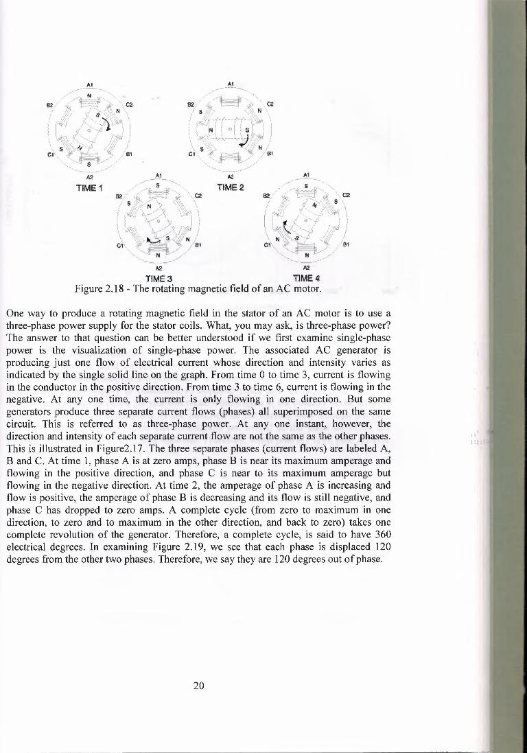
This "rotating magnetic fields of the stator can be better understoodby examining Figure2.18. As shown, the stator has six magnetic poles and the rotor has two poles. At time 1,stator poles A-1 and C-2 are north poles and the opposite poles, A-2 and C-1, are southpoles. The S-pole of the rotor is attracted by the two N-poles of the stator and the N-poleof the rotor is attracted by the two south poles of the stator. At time 2, the polarity of thestator poles is changed so that now C-2 and B-1 and N-poles and C-1 and B-2 are Spoles. The rotor then is forced to rotate 60 degrees to line up with the stator poles asshown. At time 3, B-1 and A-2 are N. At time 4, A-2 and C-1 are N. As each change ismade, the poles of the rotor are attracted by the opposite poles on the stator. Thus, as themagnetic field of the stator rotates, the rotor is forced to rotate with it.
19
TIME1~
TIME2·,,,\C2
T1ME3 TlME4 Figure 2.18 - The rotating magnetic field of an AC motor.
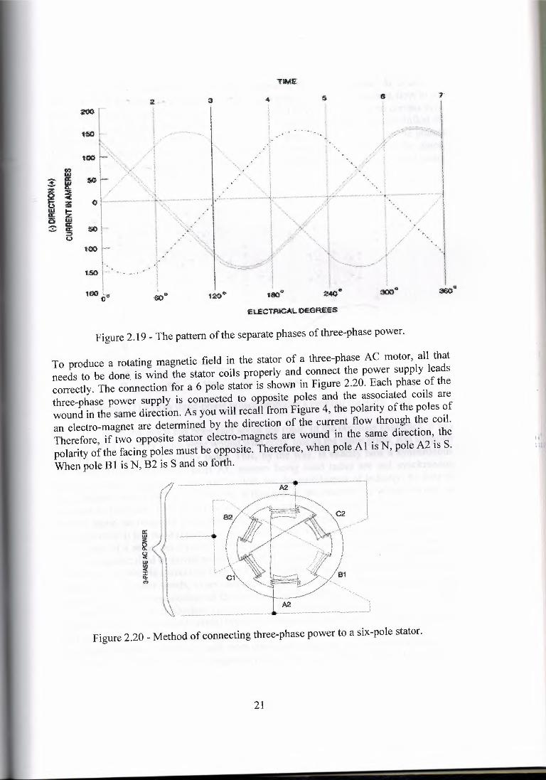
One way to produce a rotating magnetic field in the stator of an AC motor is to use athree-phase power supply for the stator coils. What, you may ask, is three-phase power?The answer to that question can be better understood if we first examine single-phasepower is. the visualization of single-phase power. The associated AC generator isproducing just one flow of electrical current whose direction and intensity varies asindicated by the single solid line on the graph. From time O to time 3, current is flowingin the conductor in the positive direction. From time 3 to time 6, current is flowing in thenegative. At any one time, the current is only flowing in one direction. But somegenerators produce three separate current flows (phases) all superimposed on the samecircuit. This is referred to as three-phase power. At any one instant, however, thedirection and intensity of each separate current flow are not the same as the other phases.This is illustrated in Figure2.l 7. The three separate phases (current flows) are labeled A,Band C. At time 1, phase A is at zero amps, phase Bis near its maximum amperage andflowing in the positive direction, and phase C is near to its maximum amperage butflowing in the negative direction. At time 2, the amperage of phase A is increasing andflow is positive, the amperage of phase B is decreasing and its flow is still negative, andphase C has dropped to zero amps. A complete cycle (from zero to maximum in onedirection, to zero and to maximum in the other direction, and back to zero) takes onecomplete revolution of the generator. Therefore, a complete cycle, is said to have 360electrical degrees. In examining Figure 2.19, we see that each phase is displaced 120degrees from the other two phases. Therefore,we say they are 120 degrees out ofphase.
20
Ii""
TIME
'I;, .• ,,• -
Figure 2.19 - The pattern of the separate phases of three-phase power.
To produce a rotating magnetic field in the stator of a three-phase AC motor, all thatneeds to be done. is wind the stator coils properly and connect the power supply leadscorrectly. The connection for a 6 pole stator is shown in Figure 2.20. Each phase of thethree-phase power supply is connected to opposite poles and the associated coils arewound in the same direction. As you will recall from Figure 4, the polarity of the poles ofan electro-magnet are determined by the direction of the current flow through the coil.Therefore, if two opposite stator electro-magnets are wound in the same direction, thepolarity of the facing poles must be opposite. Therefore, when pole Al is N, pole A2 is S.When pole B 1 is N, B2 is S and so forth.
ıı...'"
Figure 2.20 - Method of connecting three-phase power to a six-pole stator.
21
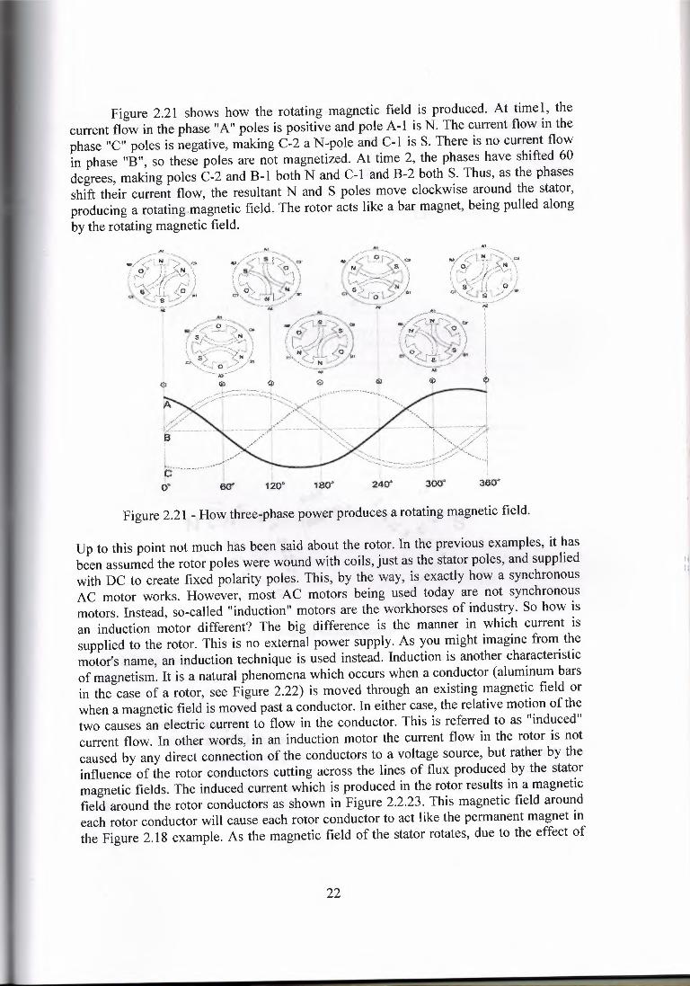
Figure 2.21 shows how the rotating magnetic field is produced. At timel, thecurrent flow in the phase "A" poles is positive and pole A-1 is N. The current flow in thephase "C" poles is negative, making C-2 a N-pole and C-1 is S. There is no current flowin phase "B", so these poles are not magnetized. At time 2, the phases have shifted 60degrees, making poles C-2 and B-1 both N and C-1 and B-2 both S. Thus, as the phasesshift their current flow, the resultant N and S poles move clockwise around the stator,producing a rotating.magnetic field. The rotor acts like a bar magnet, being pulled alongby the rotating magnetic field.
Figure 2.21 - How three-phase power produces a rotating magnetic field.
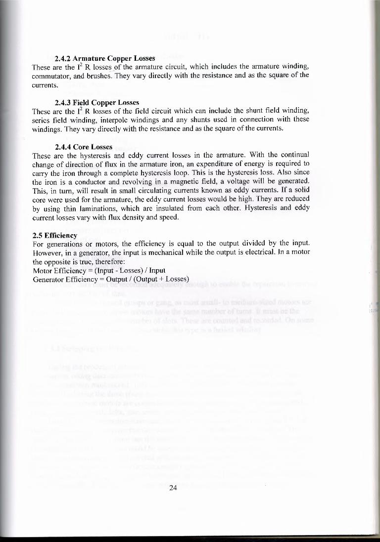
Up to this point not much has been said about the rotor. In the previous examples, it hasbeen assumed the rotor poles were wound with coils, just as the stator poles, and suppliedwith DC to create fixed polarity poles. This, by the way, is exactly how a synchronousAC motor works. However, most AC motors being used today are not synchronousmotors. Instead, so-called "induction" motors are the workhorses of industry. So how isan induction motor different? The big difference is the manner in which current issupplied to the rotor. This is no external power supply. As you might imagine from themotor's name, an induction technique is used instead. Induction is another characteristicof magnetism. It is a natural phenomena which occurs when a conductor (aluminum barsin the case of a rotor, see Figure 2.22) is moved through an existing magnetic field orwhen a magnetic field is moved past a conductor. In either case, the relative motion of thetwo causes an electric current to flow in the conductor. This is referred to as "induced"current flow. In other words, in an induction motor the current flow in the rotor is notcaused by any direct connection of the conductors to a voltage source, but rather by theinfluence of the rotor conductors cutting across the lines of flux produced by the statormagnetic fields. The induced current which is produced in the rotor results in a magneticfield around the rotor conductors as shown in Figure 2.2.23. This magnetic field aroundeach rotor conductor will cause each rotor conductor to act like the permanent magnet inthe Figure 2. 18 example. As the magnetic field of the stator rotates, due to the effect of
I.ı,,
22
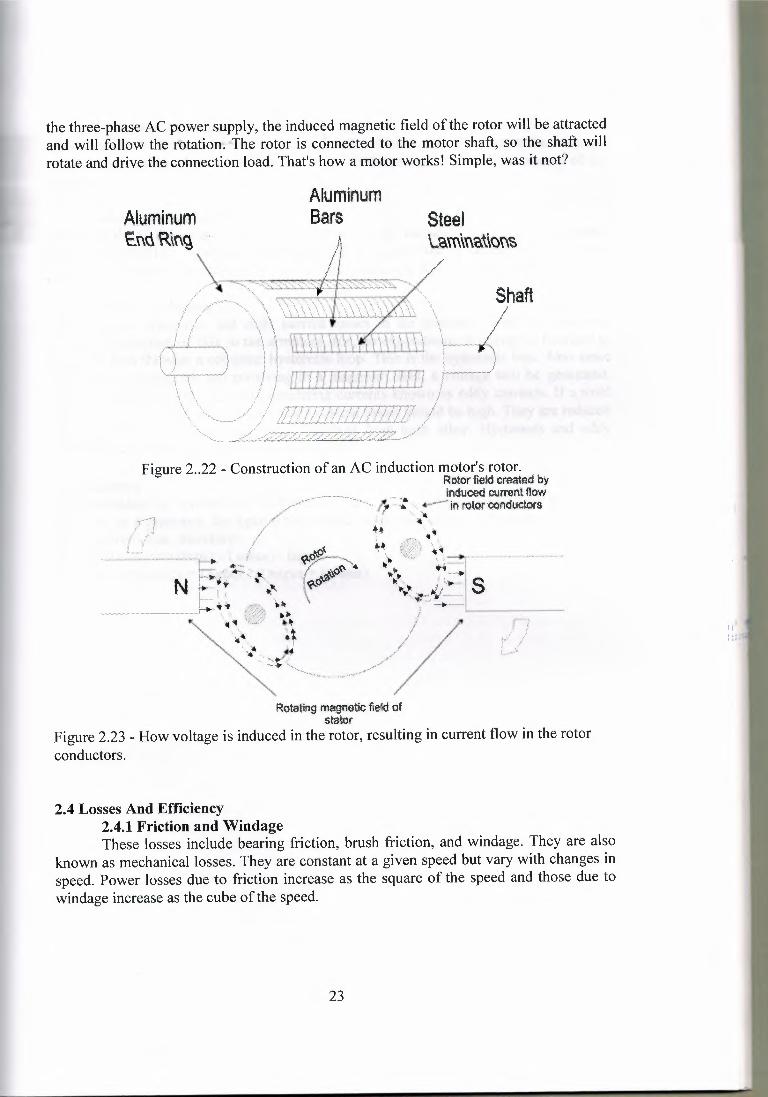
Steellam\na\\cn~
the three-phaseAC power supply, the induced magnetic field of the rotor will be attractedand will follow the rotation. The rotor is connected to the motor shaft, so the shaft willrotate and drive the connection load. That's how a motor works! Simple,was it not?
AluminumEnd'R\n~ ..
AluminumBars
Shaft
Figure 2..22 - Constructionof an AC induction motor's rotor.Rotor·fie.ld created by
- . fnduced current flowq ,,,; :: ·· -; +"'-~'""ın rotor oonductora
-~-,•..•..\ıt
Rotating tnagrıetie flood ofs!aitor
Figure 2.23 - How voltage is induced in the rotor, resulting in current flow in the rotorconductors.
2.4 Losses And Efficiency2.4.1 Friction and WindageThese losses include bearing friction, brush friction, and windage. They are also
known as mechanical losses. They are constant at a given speed but vary with changes inspeed. Power losses due to friction increase as the square of the speed and those due towindage increase as the cube of the speed.
23
2.4.2 Armature Copper LossesThese are the 12 R losses of the armature circuit, which includes the armature winding,commutator, and brushes. They vary directly with the resistance and as the square of thecurrents.
2.4.3 Field Copper LossesThese are the ı2 R losses of the field circuit which can include the shunt field winding,series field winding, interpole windings and any shunts used in connection with thesewindings. They vary directly with the resistance and as the square of the currents.
2.4.4 Core LossesThese are the hysteresis and eddy current losses in the armature. With the continualchange of direction of flux in the armature iron, an expenditure of energy is required tocarry the iron through a complete hysteresis loop. This is the hysteresis loss. Also sincethe iron is a conductor and revolving in a magnetic field, a voltage will be generated.This, in tum, will result in small circulating currents known as eddy currents. If a solidcore were used for the armature, the eddy current losses would be high. They are reducedby using thin laminations, which are insulated from each other. Hysteresis and eddycurrent losses vary with flux density and speed.
2.5 Efficiency For generations or motors, the efficiency is equal to the output divided by the input.However, in a generator, the input is mechanical while the output is electrical. In a motorthe opposite is true, therefore:Motor Efficiency = (Input - Losses) I InputGenerator Efficiency= Output I (Output+ Losses)
24
Chapter III
Rewinding the Three-Phase Motor
Many separate steps are involved in rewinding are three-phase motor, as flows:1. Taking data2. Stripping the winding3. Insulating the stator4. Winding the coils5. Placing the coils in the slots6. Connecting the coils7. Testing the winding8. Varnishing and baking
The following information is recorded:1. Name plate data2. Number of slots3. Number of coils4. Type of connection5. Number ofturns per coil6. Size of coil7. Pitch of coil8. Kind of insulation9. Size and kind wire
3.1 Taking data
All these data must be recorded adequately enough to enable the repairman to rewindthe motor without loss of time.
if the coils were wound groups or gang, as most small- to medium-sized motors arewound. All coils in three-phase motors have the same number of turns. It must be thenumber of coils is equal to the number of slots. These are counted and recorded. On somemotors, there are half as many coils as slots; this type is a basket winding.
3.2 Stripping the Winding
During the process of stripping the winding, the remainder of the informationnecessary in taking data can be obtained. Before the wires are removed from the stator,type of connection must record. This can be only be obtained if one is familiar withmethods of winding the three-phase motor and connection the phases and poles to oneanother. Three-phase motors are connected for single voltage, dual voltage, two speed,three speed, four speed, delta, star, series, parallel, and any combination thereof.
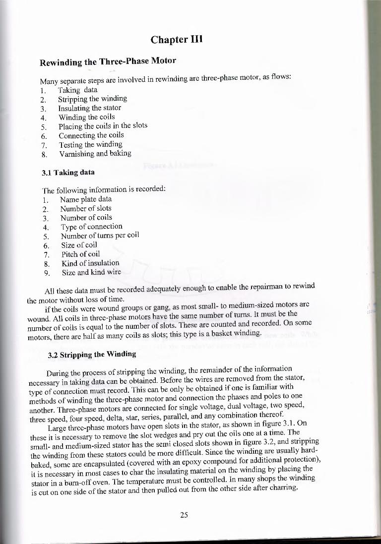
Large three-phase motors have open slots in the stator, as shown in figure 3.1. Onthese it is necessary to remove the slot wedges and pry out the oils one at a time. Thesmall- and medium-sized stator has the semi closed slots shown in figure 3.2, and strippingthe winding from these stators could be more difficult. Since the winding are usually hardbaked, some are encapsulated (covered with an epoxy compound for additional protection),it is necessary in most cases to char the insulating material on the winding by placing thestator in a bum-off oven. The temperature must be controlled. In many shops the windingis cut on one side of the stator and then pulled out from the other side after charring.
25
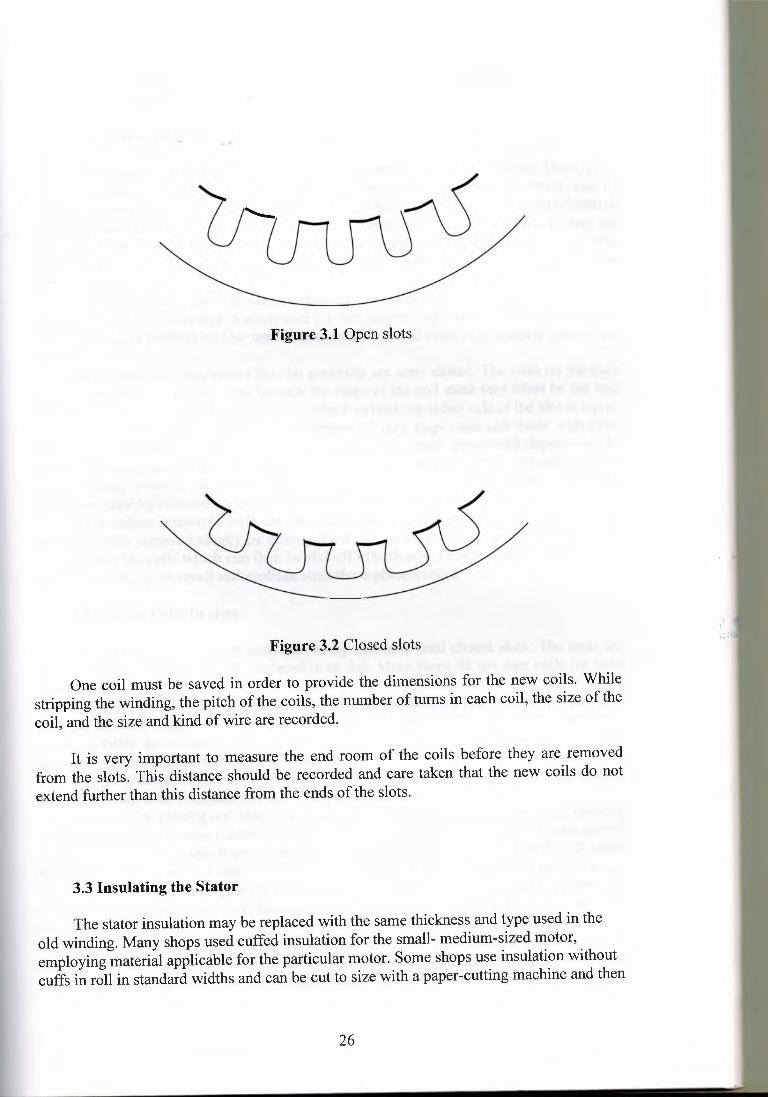
Figure 3.1 Open slots
II
Figure 3.2 Closed slots,,,
One coil must be saved in order to provide the dimensions for the new coils. Whilestripping the winding, the pitch of the coils, the number of turns in each coil, the size of thecoil, and the size and kind of wire are recorded.
It is very important to measure the end room of the coils before they are removedfrom the slots. This distance should be recorded and care taken that the new coils do notextend further than this distance from the ends of the slots.
3.3 Insulating the Stator
The stator insulation may be replaced with the same thickness and type used in theold winding. Many shops used cuffed insulation for the small- medium-sized motor,employing material applicable for the particular motor. Some shops use insulation withoutcuffs in roll in standard widths and can be cut to size with a paper-cutting machine and then
26
shaped to fit the side of the slots. May shops use a small machine called an insulationformer for this purpose.
3.4 Winding the Coils
Examination of a coil taken from a stator will reveal that it has six sides. This type isclad a diamond coil, and the winding is called a diamond-coil winding. However, coil ofthe smaller motor may have only four sides, two of which rounded. It should be understoodthat poly phase motor coils are always wound on forms, or coil winding heads as they arecalled, and then installed in the slots. Motors up to approximately 75 HP are wound with"mush"-type coils. This name has been given to these coils because they are wound inrandom rather in layers.
On the large three-phase motor, the slots are generally open, and the coils are usuallycompletely taped. Cotton tape is often used for this purpose, although varnished cambric orfiberglass tape is preferable. Use tape combination with the class of insulation used in themotor.
On the medium-sized motor the slot generally are semi closed. The coils on the suchmotors cannot be completely tape because the turns of the coil must very often be fed intothe slot one at a time. Only that part of coil which extends on either side of the slot is taped.
Most polyphase motors, with the exception of very large ones and those with openslots, use coils wound in group. The number of coils in each group will depend on thenumber of slots and number of poles. This practice of winding coils in groups is calledgroup or gang winding. In group winding several coils are wound before the wire is cut.This saves time by elimination the necessity of connecting coils to one another or stubbing.. This type makes must-type coils for any three-phase motor up to 75 HP. The finishedcoils are easily removed simply by pulling the arms out slightly and turning them inward.This unlocks the coils which can then be slid off effortlessly. Group-wound coils are usedalmost exclusively on small and medium sizes three-phase motors.
3.5 Placing Coils In slots 'I,,,,The turns of the coils are inserted one by one into semi closed slots. The ends are
sometimes taped after each coil is placed in to slot. Most shops do not tape coils for semiclosed slots.
Use the flowing procedure: Spread or fan out the turns on one side of the coil, andhold the coil at an angle so that all the turns can be fed into slot. Make sure that each turnsis placed inside the insulation. Sometimes the wires are placed between the insulation andthe iron core by mistake, and a group result.
Pull the side of the coil thought the slot until all turns are in the slot. The other side ofthe coil remains free. Note that coil side occupies half a slot.
Continue by placing one side öf the second coil in the slot beyond the first. Flowingcoils are fitted in the same manner until the slots of a complete coil pitch hold one side ofeach coil. The second side of each coil is left out until the bottom half of a slot is occupiedby a coil side. The second side of each coil is then fitted on top of the firs side of a coilseveral slots away, according to the pitch of the coil. When coils are wound in groups, thewinder always works with a complete group of coils at a time, placing them into the slotsas explained above.
In this method one side of each coil is the bottom half of a slot and the other side ofthe coil is in the top half of another slot several slots away, depending on the pitch of thecoil. The number of coils of which the top side is left out is usually one or two more than
27
the coil pitch, and they are not put into slots until the stator is nearly completed. Makecertain that each coil side extends beyond the slot at both ends and does not press againstthe iron core at the comers.
Before inserting the second side of each coil, it is necessary to insulate it from the coilalready in to slot.
To insulate between the coil sides in the same slot, follow the procedure: for bothopen and semi closed slots. A creased separator or insulation of the proper width andthickness is used to insulate between top and bottom coils sides in the slot. Slide aseparator over the bottom sides of the coil in the slot before installing the top side. It shouldextend about 1 .Sem beyond the slot ends. When the top side is placed into the slot, slip awooden or formed fiber wedge (round or square) over the top coil. This should extendabout a 30mm beyond the slot ends. As each group of coils is placed in the slots, phaseinsulation must be used between groups. Varnished or glass cambric or canvas is used forthis purpose. Phase insulation between groups. Heavy separators are placed between coilsin the slot and U-shaped insulators over the top coils. Slot wedges are inserted to hold thecoils securely in place. Note also that coils are wound with three wires in parallel.
3.6 Connection the Three-phase Motor
All three-phase motors are wound with a number of coils, usually as many coils asslots. These coils are so connected as to produce three separate windings called phases, andeach of which must have the same number of coils. The number of coils in each phase mustbe one-third the total numbers of coils in the stator.
Therefore, if a three-phase motor has 36 coils, each phase will have 12 coils. Thesephases are usually called phase R, phase S, and phase T.
Rule 1. To find number of coils in each phase, divide the total number of coils in themotor by the number of phases.
Rule 2. To find the number of coils in each pole, divide the total number of coils bythe number of poles.
Rule 3. A simple method to determine the number of groups is to multiply thenumber of poles by the number of phases. For example, 4 pole X 3 phase= 12 groups, orgroups=polseXphase.
If the number of groups is known, it is easy to determine the number of coils in eachgroup.
Connection type of three-phase motor1. Star(wye) connection2. Delta connection3. Parallel connection
3. 7 Troubleshooting
The there-phase motors should be given tests for the following defects after a repairor winding job: grounds, opens, shorts and reverses.
28
Chapter IV
Alternating-current motor control
4.1.1 Contactors
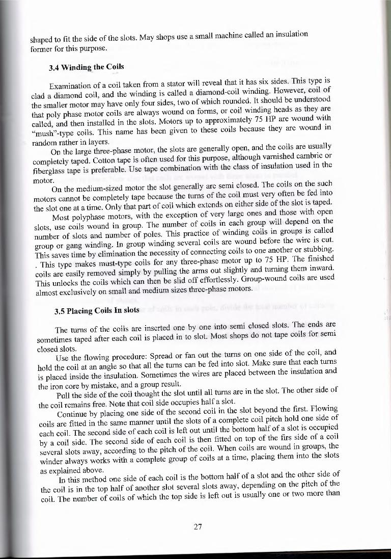
Contactor is illustrated in figure 4. 1 . A contactor, which a motor connectsdirectly across line. Normally contactor has three normally open main contacts whichwhen closed connect' the directly on the line. It also has a magnetic holding coil, whichcloses the main contacts upon being energized, and also closes a normally openauxiliary or maintaining contact to maintain the current in the holding coil. It isobvious that any size of magnetic switch can be operated just by sending a smallcurrent through the coil.
J_ J_ J_ TTT
Figure 4.1 Contactor symbol [1]
The holding coil on an a-c magnetic is exited by a pulsating current, andtherefore its pull is not continuous, but rather alternates according to thefrequency of the current. This tends to cause chattering; to overcome thiscondition, the core of the magnet is equipped with a shading coil, which producesan-out-of-phase flux. The shading coil is a small, single-turn copper coil, which isembedded around a portion of the core tip. The current induced in this coil issufficient for the magnet to retain the contactor during the reversal of current.
4.1.2 Overload Relays
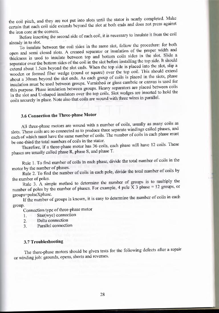
Nearly all-magnetic starters are equipped with an overload device to protectthe motor from excessive current. The thermal overload relay may be bimetallic type.
A thermal relay is illustrated in figure 4.2 . This bimetallic type of relayconsist of small heater coil or strip which is connected in series with the line andwhich generates heat by virtue of the current flowing through it; the amount of heatgenerated depend on the current flow in the line. Mounted adjacent to, or directlyinside, the coil is a strip formed of two metals. This is fixed at one end, the other endbeing free to move. The two metals have different degrees expansion, and the stripwill bend when heated. The free end normally keeps two contacts of the controlcircuit closed. When an overload occurs, the heater heats the thermostatic bimetal sothat it will bend and separate the two contacts, thereby opening the holding-coilcircuit and stopping the motor. The bimetallic type of overload relay is usuallydesigned with a feature, which permits automatic resetting, although it is alsodesigned for manual resetting. Some overload relays are ambient-compensated toprovide maximum protection where the temperature surrounding the relay differsfrom the temperature surrounding the motor. A number of manufactures feature a
29
bimetallic overload relay, which can be converted from manual to automatic bypositioning a reset selector lever. Automatic reset is desirable where control is notreadily accessible or regularly attended. Some overload relays are trip free. Thismeans that the starter contacts cannot be held closed during an overload and causedamage to the motor .
.ı.___ n _ ___ n _ __ nL---
Figure 4.2 Overload relay symbol and photograph [2]
4.1.3 Time Relays
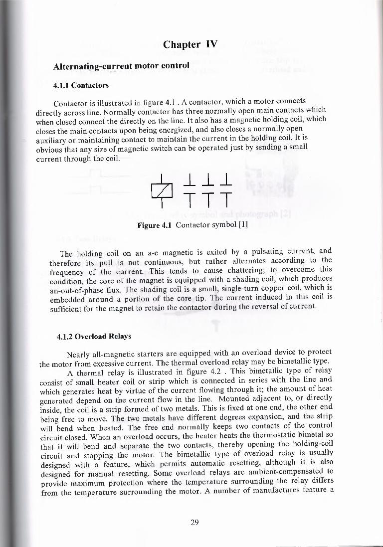
Time relay is illustrated in figure 4.3 . A device whit either mechanically orsolid state output contacts that perform a timing function upon energization orcontrol signal
~• T
Figure 4.3 Time relay symbol and photograph [5]
4.1.4 Pushbutton Stations
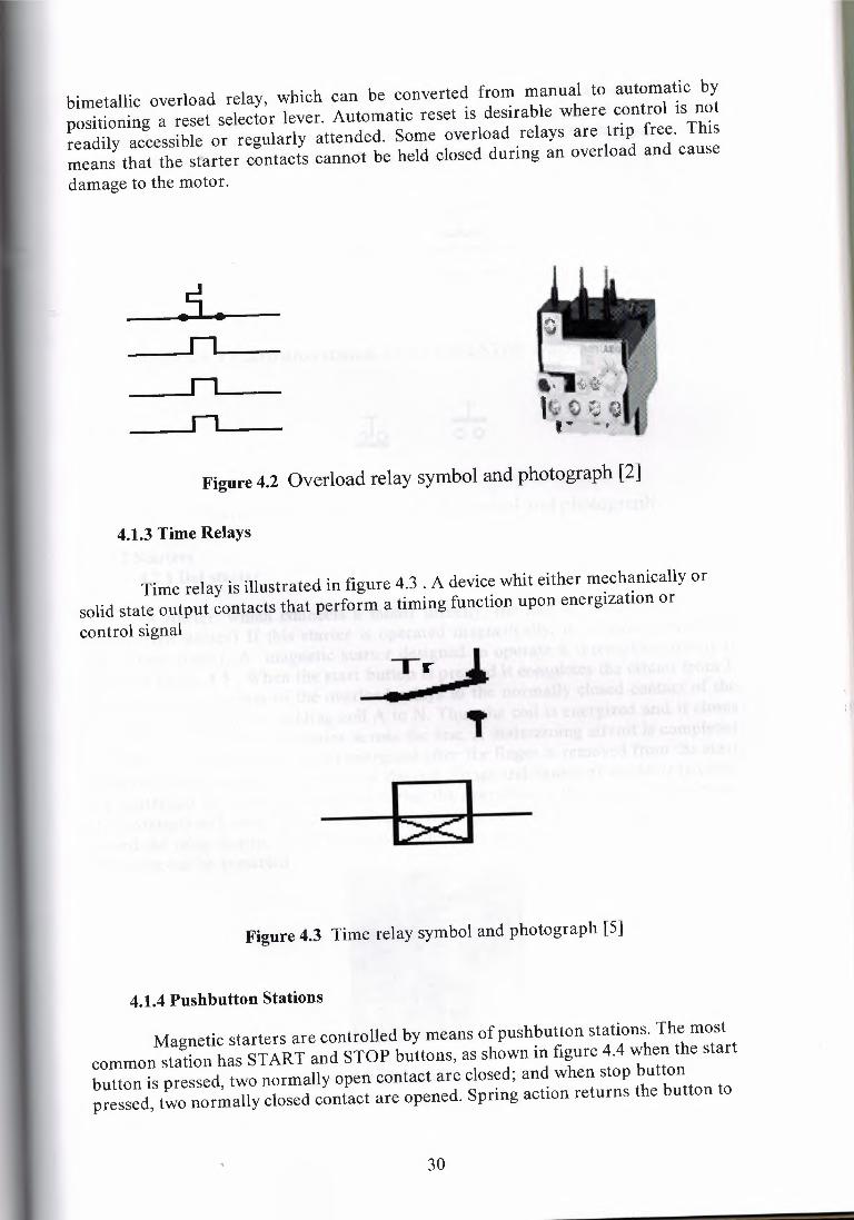
Magnetic starters are controlled by means of pushbutton stations. The mostcommon station has START and STOP buttons, as shown in figure 4.4 when the startbutton is pressed, two normally open contact are closed; and when stop buttonpressed, two normally closed contact are opened. Spring action returns the button to
30
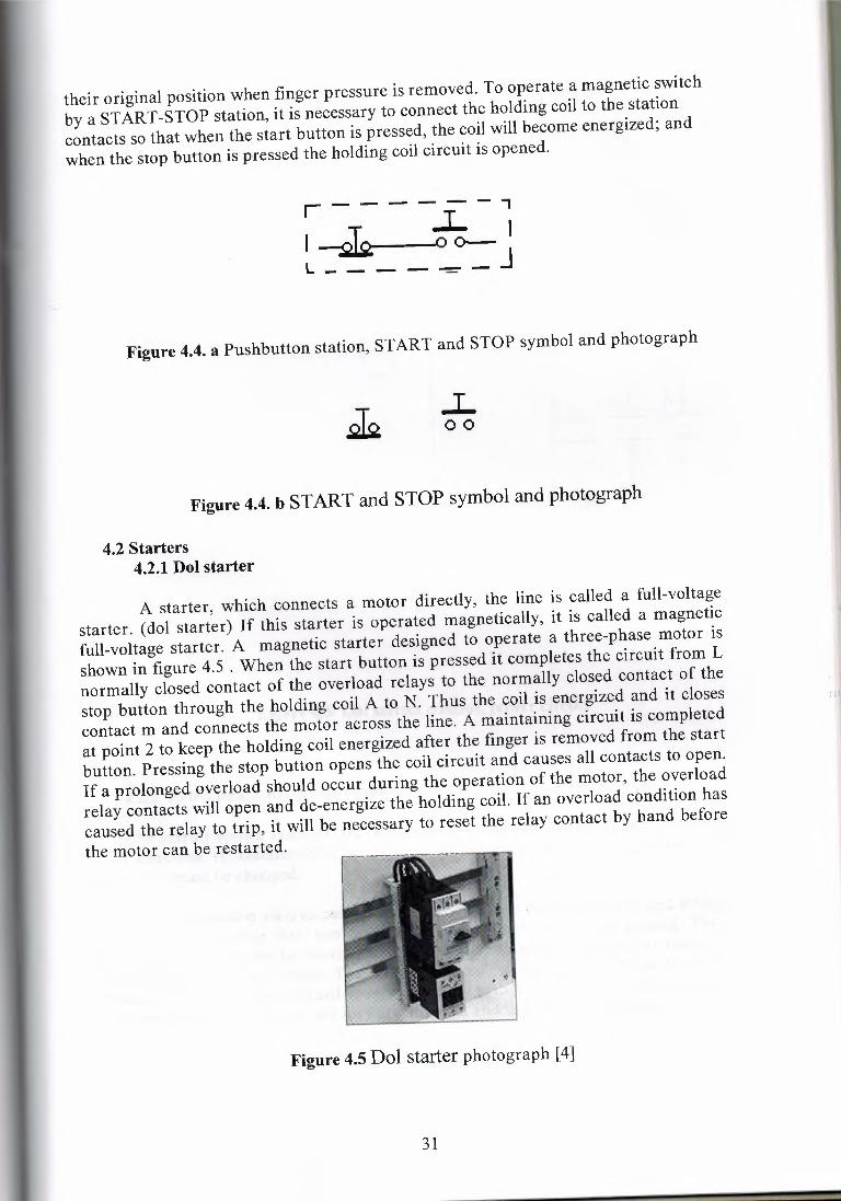
their original position when finger pressure is removed. To operate a magnetic switchby a START-STOP station, it is necessary to connect the holding coil to the stationcontacts so that when the start button is pressed, the coil will become energized; andwhen the stop button is pressed the holding coil circuit is opened.
- - - ,r--- .L I~0-JI --L---- -
Figure 4.4. a Pushbutton station, START and STOP symbol and photograph
.L00
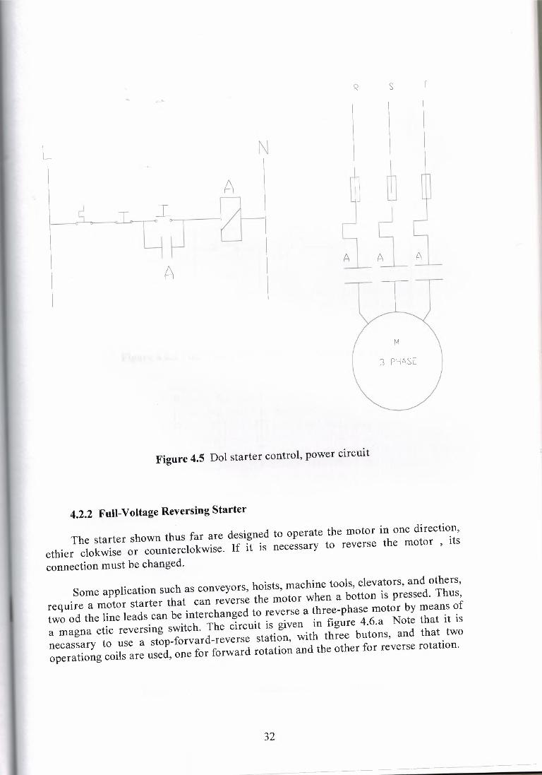
Figure 4.4. b START and STOP symbol and photograph
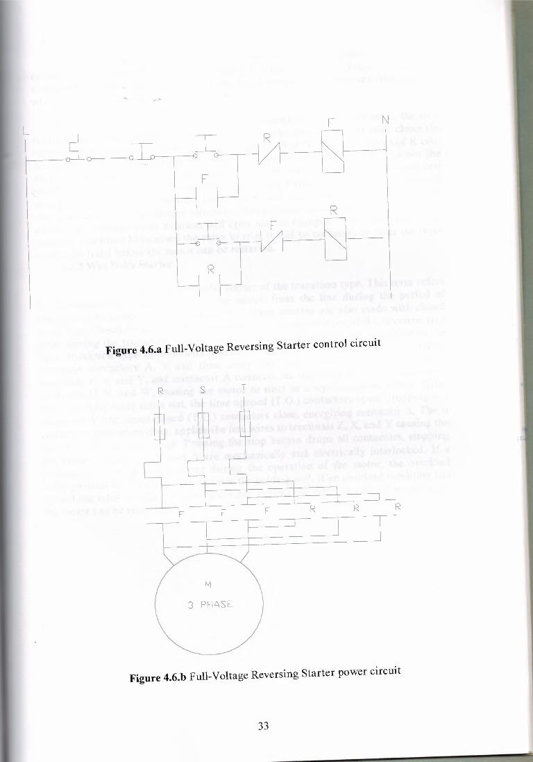
4.2 Starters4.2.1Dol starter
A starter, which connects a motor directly, the line is called a full-voltagestarter. (dol starter) If this starter is operated magnetically, it is called a magneticfull-voltage starter. A magnetic starter designed to operate a three-phase motor isshown in figure 4.5 . When the start button is pressed it completes the circuit from Lnormally closed contact of the overload relays to the normally closed contact of thestop button through the holding coil A to N. Thus the coil is energized and it closescontact m and connects the motor across the line. A maintaining circuit is completedat point 2 to keep the holding coil energized after the finger is removed from the startbutton. Pressing the stop button opens the coil circuit and causes all contacts to open.If a prolonged overload should occur during the operation of the motor, the overloadrelay contacts will open and de-energize the holding coil. If an overload condition hascaused the relay to trip, it will be necessary to reset the relay contact by hand beforethe motor can be restarted.
Figure 4.5 Dol starter photograph [4]
31
R s T
L N
A
A A A
A
M
3 PHASE
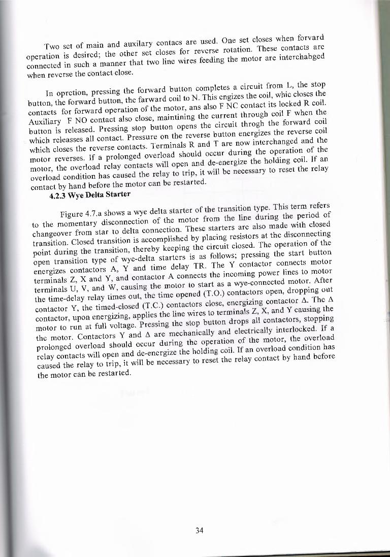
Figure 4.5 Dol starter control, power circuit
4.2.2 Full-Voltage Reversing Starter
The starter shown thus far are designed to operate the motor in one direction,ethier clokwise or counterclokwise. If it is necessary to reverse the motor , itsconnection must be changed.
Some application such as conveyors, hoists, machine tools, elevators, and others,require a motor starter that can reverse the motor when a botton is pressed. Thus,two od the line leads can be interchanged to reverse a three-phase motor by means ofa magna etic reversing switch. The circuit is given in figure 4.6.a Note that it isnecassary to use a stop-forvard-reverse station, with three butons, and that twooperationg coils are used, one for forward rotation and the other for reverse rotation.
32
R
#~
LI R
F N
) C
F µI F
R,---
:) C
R
Figure 4.6.a Full-Voltage Reversing Starter control circuit
R s T
M
3 PHASE
Figure 4.6.b Full-Voltage Reversing Starter power circuit
33
In opretion, pressing the forward button completes a circuit from L, the stopbutton, the forward button, the forward coil to N. This engizes the coil, whic closes thecontacts for forward operation of the motor, ans also F NC contact its locked R coil.Auxiliary F NO contact also close, maintining the current through coil F when thebutton is released. Pressing stop button opens the circuit throgh the forward coilwhich releasses all contact. Pressure on the reverse button energizes the reverse coilwhich closes the reverse contacts. Terminals R and T are now interchanged and themotor reverses. If a prolonged overload should occur during the operation of themotor, the overload relay contacts will open and de-energize the holding coil. If anoverload condition has caused the relay to trip, it will be necessary to reset the relaycontact by hand before the motor can be restarted.
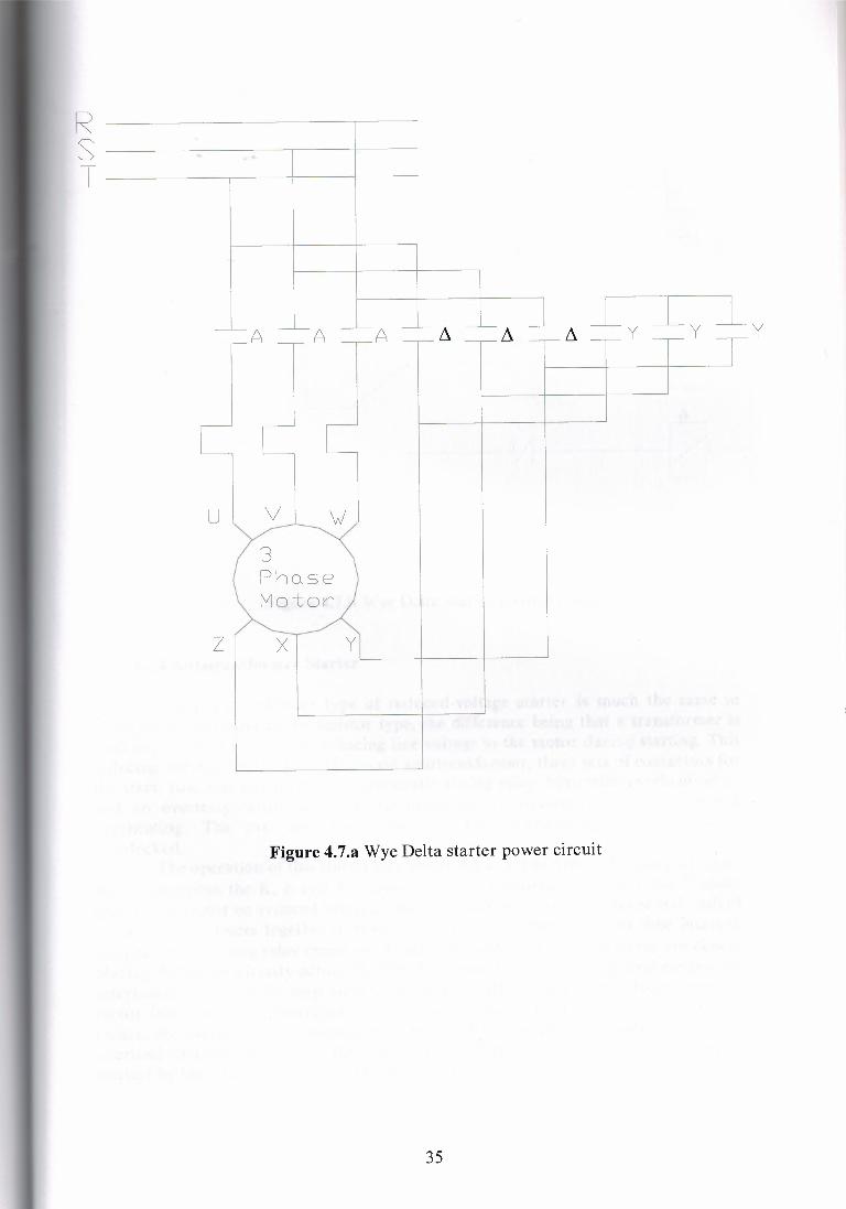
4.2.3 Wye Delta Starter
Two set of main and auxilary contacs are used. One set closes when forvardoperation is desired; the other set closes for reverse rotation. These contacts areconnected in such a manner that two line wires feeding the motor are interchabgedwhen reverse the contact close.
Figure 4.7.a shows a wye delta starter of the transition type. This term refersto the momentary disconnection of the motor from the line during the period ofchangeover from star to delta connection. These starters are also made with closedtransition. Closed transition is accomplished by placing resistors at the disconnectingpoint during the transition, thereby keeping the circuit closed. The operation of theopen transition type of wye-delta starters is as follows; pressing the start buttonenergizes contactors A, Y and time delay TR. The Y contactor connects motorterminals Z, X and Y, and contactor A connects the incoming power lines to motorterminals U, V, and W, causing the motor to start as a wye-connected motor. Afterthe time-delay relay times out, the time opened (T.0.) contactors open, dropping outcontactor Y, the timed-closed (T.C.) contactors close, energizing contactor /ı. The /ıcontactor, upon energizing, applies the line wires to terminals Z, X, and Y causing themotor to run at full voltage. Pressing the stop button drops all contactors, stoppingthe motor. Contactors Y and /ı are mechanically and electrically interlocked. If aprolonged overload should occur during the operation of the motor, the overloadrelay contacts will open and de-energize the holding coil. If an overload condition hascaused the relay to trip, it will be necessary to reset the relay contact by hand beforethe motor can be restarted.
34
... ...'-
J_
RsT
A A A
U l V.~
3PhQse Motor
z X y
Figure 4.7.a Wye Delta starter power circuit
35
L NA
TrlA
yTrl
y
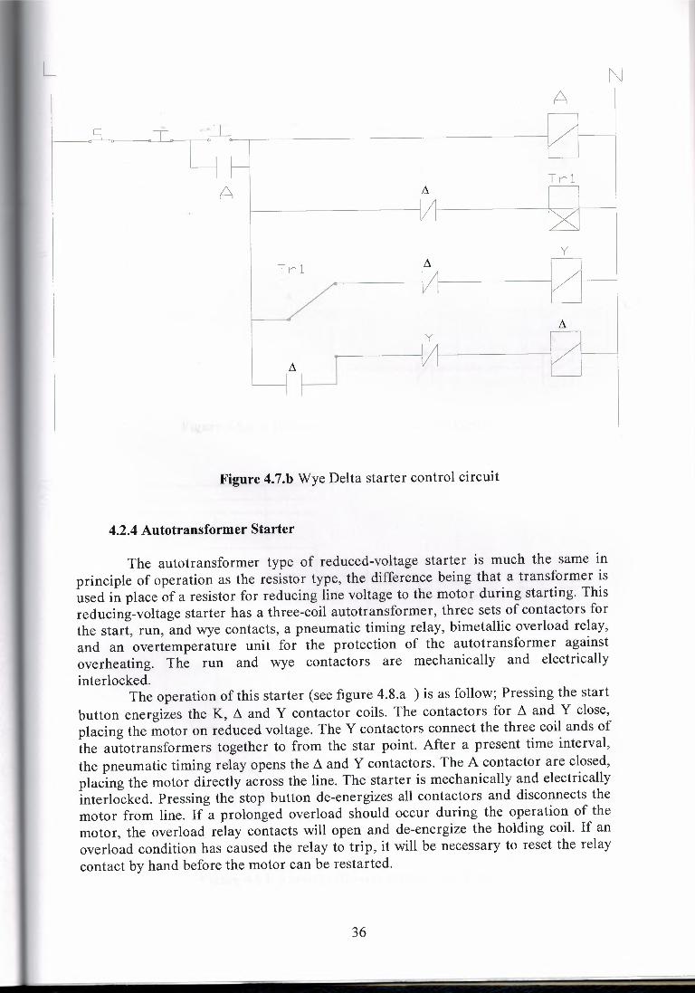
Figure 4.7.b Wye Delta starter control circuit
4.2.4 Autotransformer Starter
The autotransformer type of reduced-voltage starter is much the same inprinciple of operation as the resistor type, the difference being that a transformer isused in place of a resistor for reducing line voltage to the motor during starting. Thisreducing-voltage starter has a three-coil autotransformer, three sets of contactors forthe start, run, and wye contacts, a pneumatic timing relay, bimetallic overload relay,and an overtemperature unit for the protection of the autotransformer againstoverheating. The run and wye contactors are mechanically and electricallyinterlocked.
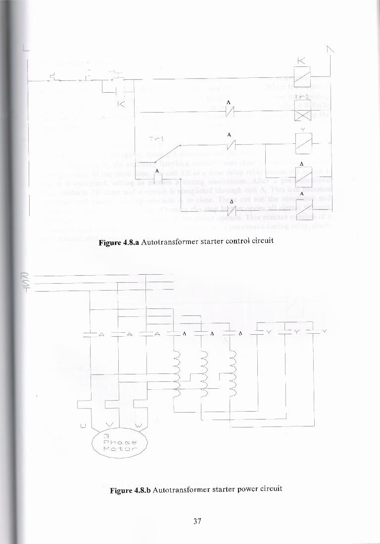
The operation of this starter (see fıgure 4.8.a ) is as follow; Pressing the startbutton energizes the K, ~ and Y contactor coils. The contactors for ~ and Y close,placing the motor on reduced voltage. The Y contactors connect the three coil ands ofthe autotransformers together to from the star point. After a present time interval,the pneumatic timing relay opens the ~ and Y contactors. The A contactor are closed,placing the motor directly across the line. The starter is mechanically and electricallyinterlocked. Pressing the stop button de-energizes all contactors and disconnects themotor from line. If a prolonged overload should occur during the operation of themotor, the overload relay contacts will open and de-energize the holding coil. If anoverload condition has caused the relay to trip, it will be necessary to reset the relaycontact by hand before the motor can be restarted.
36
L NK
K A
TrlA
y
A
A
Figure 4.8.a Autotransformer starter control circuit
RsT ~~~~-,-~~+-~----t-~~
A A A
u vı w ~3Pho.seMo-tor
Figure 4.8.b Autotransformer starter power circuit
37
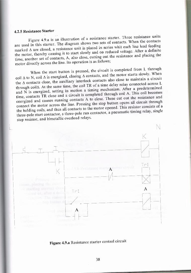
4.2.5 Resistance Starter
Figure 4.9.a is an illustration of a resistance starter. Three resistance unitsare used in this starter. The diagram shows two sets of contacts. When the contactsmarked !ı are closed, a resistance unit is placed in series whit each line lead feedingthe motor, thereby causing it to start slowly and on reduced voltage. After a definitetime, another set of contacts, A, also close, cutting out the resistance and placing themotor directly across the line. Its operation is as follows;
When the start button is pressed, the circuit is completed from L throughcoil !ı to N, coil !ı is energized, closing !ı contacts, and the motor starts slowly. Whenthe !ı contacts close, the auxiliary interlock contacts also close to maintain a circuitthrough coilzs. At the same time, the coil TR of a time delay relay connected across Land N is energized, setting in motion a timing mechanism. After a predeterminedtime, contacts TR close and a circuit is completed through coil A. This coil becomesenergized and causes running contacts A to close. These cut out the resistance andconnect the motor across the line. Pressing the stop button opens all circuit throughthe holding coils, and thus all contacts to the motor opened. This resistor consists of athree-pole start contactor, s three-pole run contactor, a pneumatic timing relay, singlestep resistor, and bimetallic overload relays.
L NK
Trl
K A
Trl A
A
Figure 4.9.a Resistance starter control circuit
38
A A
RsT
A-~K
u V
3Ph0seMotor
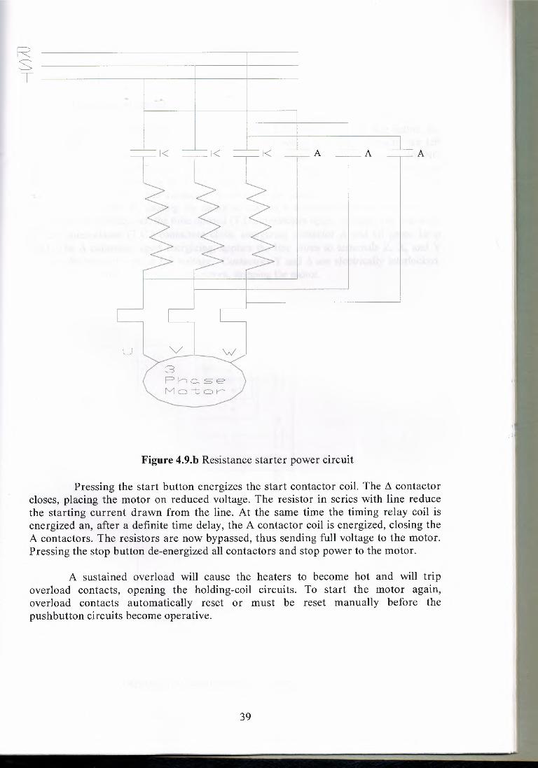
Figure 4.9.b Resistance starter power circuit
Pressing the start button energizes the start contactor coil. The L1 contactorcloses, placing the motor on reduced voltage. The resistor in series with line reducethe starting current drawn from the line. At the same time the timing relay coil isenergized an, after a definite time delay, the A contactor coil is energized, closing theA contactors. The resistors are now bypassed, thus sending full voltage to the motor.Pressing the stop button de-energized all contactors and stop power to the motor.
A sustained overload will cause the heaters to become hot and will tripoverload contacts, opening the holding-coil circuits. To start the motor again,overload contacts automatically reset or must be reset manually before thepushbutton circuits become operative.
39
Chapter V
Project
5.1 Operation of circuit
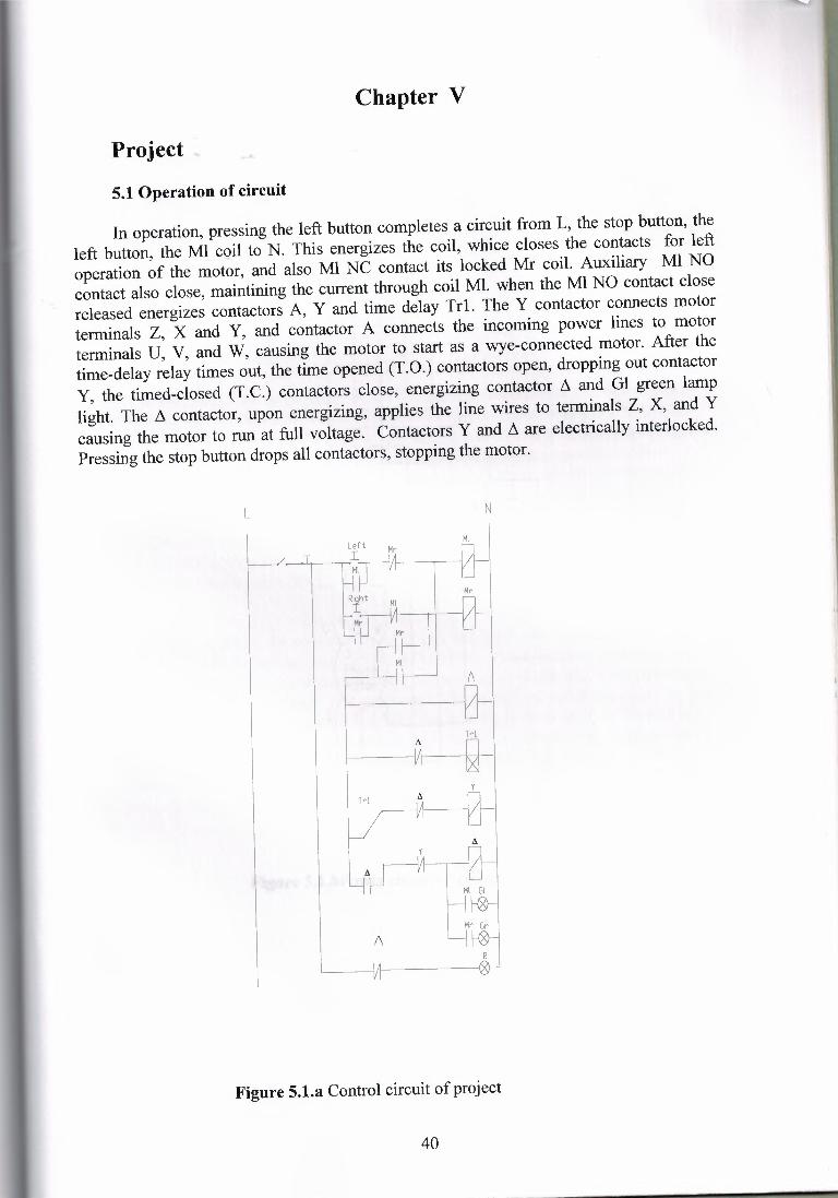
In operation, pressing the left button completes a circuit from L, the stop button, theleft button, the Ml coil to N. This energizes the coil, whice closes the contacts for leftoperation of the motor, and also Ml NC contact its locked Mr coil. Auxiliary Ml NOcontact also close, maintining the current through coil Ml. when the Ml NO contact closereleased energizes contactors A, Y and time delay Trl. The Y contactor connects motorterminals Z, X and Y, and contactor A connects the incoming power lines to motorterminals U, V, and W, causing the motor to start as a wye-connected motor. After thetime-delay relay times out, the time opened (T.O.) contactors open, dropping out contactorY, the timed-closed (T.C.) contactors close, energizing contactor /'ı and Gl green lamplight. The /'ı contactor, upon energizing, applies the line wires to terminals Z, X, and Ycausing the motor to run at full voltage. Contactors Y and /'ı are electrically interlocked.Pressing the stop button drops all contactors, stopping the motor.
L N
Trl
Trl
A
Ml GIkı}--1
Mr~I
Figure 5.1.a Control circuit of project
40
RsT
I- Ml=Ml=Ml=Mr Mr_Mr
A -A =A
z I xi Y
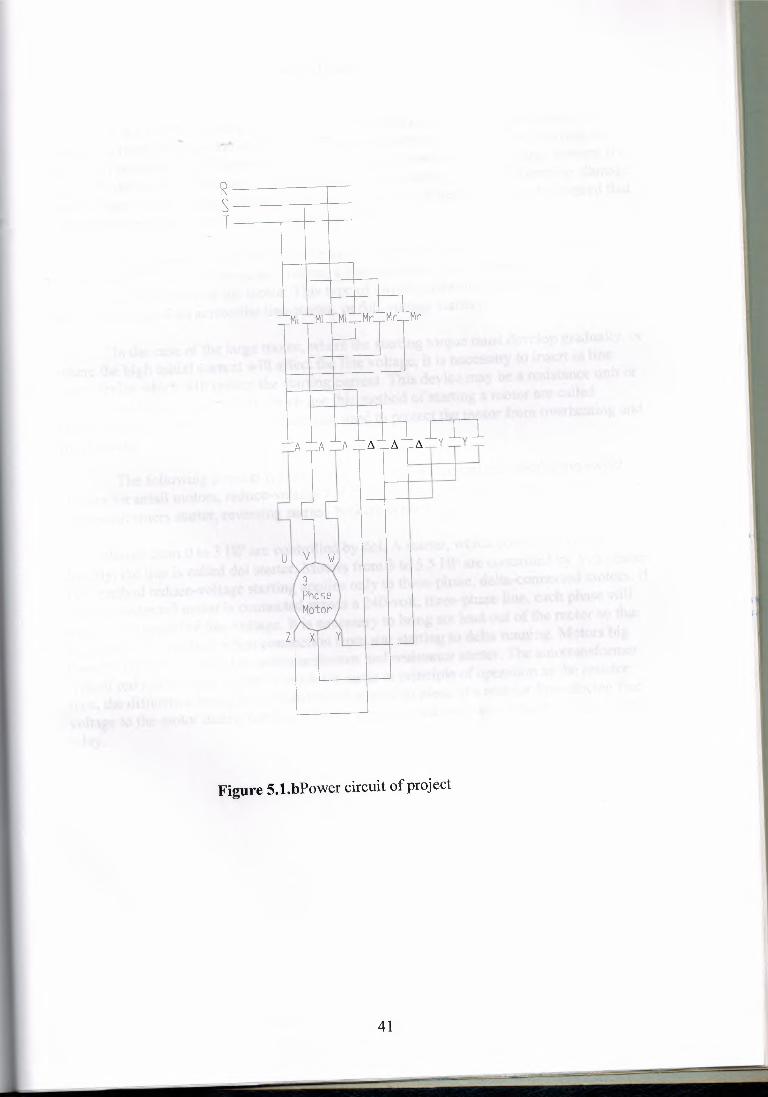
Figure 5.1.bPower circuit of project
41
CONCLUSION
If an a-c motor is started on full voltage, it will draw from two to six times its normalrunning current. Because the motor is constructed to withstand the shock of starting, noharm will be caused by this excessive flow of current. However, on very large motors, it isgenerally desirable to take some measure to reduce the starting current; otherwise, damagemay be done the machinery driven by the motor, and line disturbances may be created thataffect the operation of other motors on the same line.
For the small motor, or where the load can stand the shock of starting and noobjectionable line disturbances are created, a hand-operated or an automatic starting switchcan be used for control of the motor. This type of switch connects the motor directly acrossthe line and called an across-the line-starter, or full-voltage starter.
In the case of the large motor, where the starting torque must develop gradually, orwhere the high initial current will affect the line voltage, it is necessary to insert in linesame device which will reduce the starting current. This device may be a resistance unit oran autotransformer. Controllers which use this method of starting a motor are calledreduce-voltage starters. Controllers are also used to protect the motor from overheating andoverloading.
The following popular types of controllers will be described: pushbutton switchstarters for small motors, reduce-voltage resistance starters, wye-delta starters, andautotransformers starter, reversing starter, braking controllers.
Motors from O to 3 HP are controlled by dol. A starter, which connects a motordirectly, the line is called dol starter. Motors from 3 to 5.5 HP are controlled by Y-/ı starter.This method reduce-voltage starting applies only to three-phase, delta-connected motors. Ifa delta-connected motor is connected across a 240-volt, three-phase line, each phase willreceive 58 percent ofline voltage. It is necessary to bring six lead out of the motor so thatthey can be interchange when connection from star starting to delta running. Motors bigthan 5.5 Hp are controlled by autotransformer and resistance starter. The autotransformertype of reduced-voltage starter is much the same in principle of operation as the resistortype, the difference being that a transformer is used in place of a resistor for reducing linevoltage to the motor during starting. Motors are protected overheat or overload by overloadrelay.
42
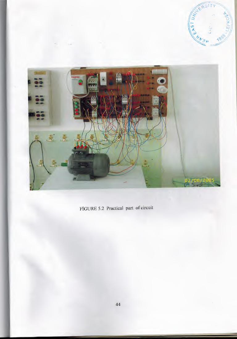
FİGURE 5.2 Practical part of circuit
44
Related Documents