Catalogue No.: 1014-b ODU DOCK Connector System for application in Robot-Docking and Tool-Changing Systems for more than 100.000 plugging cycles 2 rue René Laennec 51500 Taissy France Fax: 03 26 85 19 08, Tel : 03 26 82 49 29 E-mail:[email protected] Site web : www.hvssystem.com

Welcome message from author
This document is posted to help you gain knowledge. Please leave a comment to let me know what you think about it! Share it to your friends and learn new things together.
Transcript

Catalogue No.: 1014-b
ODU DOCK
Connector System for application in Robot-Docking and Tool-Changing
Systems for more than 100.000 plugging cycles
2 rue René Laennec 51500 Taissy FranceFax: 03 26 85 19 08, Tel : 03 26 82 49 29
E-mail:[email protected] web : www.hvssystem.com

ODU DOCK
Seite 2 ODU Steckverbindungssysteme GmbH & Co. KG, Pregelstraße 11, D – 84453 Mühldorf/Inn, Tel.: +49/8631/6156-0, Fax: +49/8631/6156-49, www.odu.de
All dimensions in mm. All figures are illustrations or photos. Changes reserved.

ODU DOCK
Seite 3 ODU Steckverbindungssysteme GmbH & Co. KG, Pregelstraße 11, D – 84453 Mühldorf/Inn, Tel.: +49/8631/6156-0, Fax: +49/8631/6156-49, www.odu.de
Contents Page Contact System and Application 4 Housing 5 Contact Inserts for Crimp Contacts / Crimping Tools 6-9 Quick-Change-Head / Crimping Tools 10-11 Contact Inserts for Solder-In Contacts 12-14
ODU DOCK
Seite 4 ODU Steckverbindungssysteme GmbH & Co. KG, Pregelstraße 11, D – 84453 Mühldorf/Inn, Tel.: +49/8631/6156-0, Fax: +49/8631/6156-49, www.odu.de
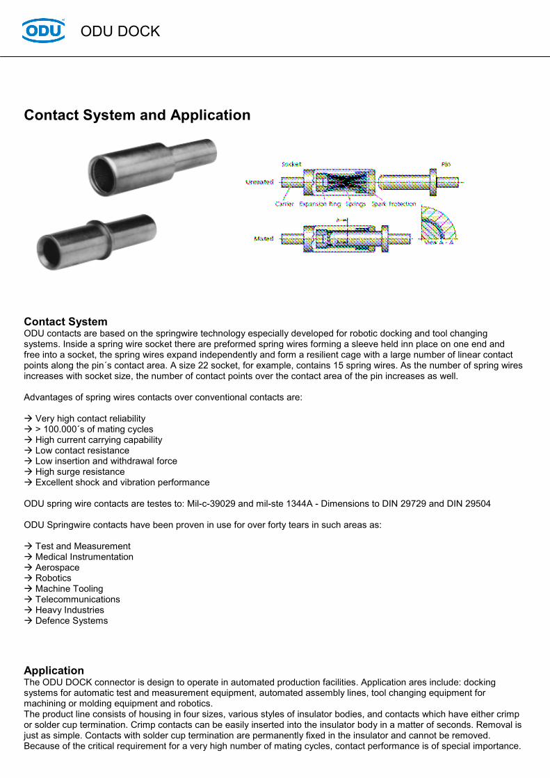
Contact System and Application
Contact System ODU contacts are based on the springwire technology especially developed for robotic docking and tool changing systems. Inside a spring wire socket there are preformed spring wires forming a sleeve held inn place on one end and free into a socket, the spring wires expand independently and form a resilient cage with a large number of linear contact points along the pin´s contact area. A size 22 socket, for example, contains 15 spring wires. As the number of spring wires increases with socket size, the number of contact points over the contact area of the pin increases as well. Advantages of spring wires contacts over conventional contacts are:
Very high contact reliability > 100.000´s of mating cycles High current carrying capability Low contact resistance Low insertion and withdrawal force High surge resistance Excellent shock and vibration performance
ODU spring wire contacts are testes to: Mil-c-39029 and mil-ste 1344A - Dimensions to DIN 29729 and DIN 29504 ODU Springwire contacts have been proven in use for over forty tears in such areas as:
Test and Measurement Medical Instrumentation Aerospace Robotics Machine Tooling Telecommunications Heavy Industries Defence Systems
Application The ODU DOCK connector is design to operate in automated production facilities. Application ares include: docking systems for automatic test and measurement equipment, automated assembly lines, tool changing equipment for machining or molding equipment and robotics. The product line consists of housing in four sizes, various styles of insulator bodies, and contacts which have either crimp or solder cup termination. Crimp contacts can be easily inserted into the insulator body in a matter of seconds. Removal is just as simple. Contacts with solder cup termination are permanently fixed in the insulator and cannot be removed. Because of the critical requirement for a very high number of mating cycles, contact performance is of special importance.
ODU DOCK
Seite 5 ODU Steckverbindungssysteme GmbH & Co. KG, Pregelstraße 11, D
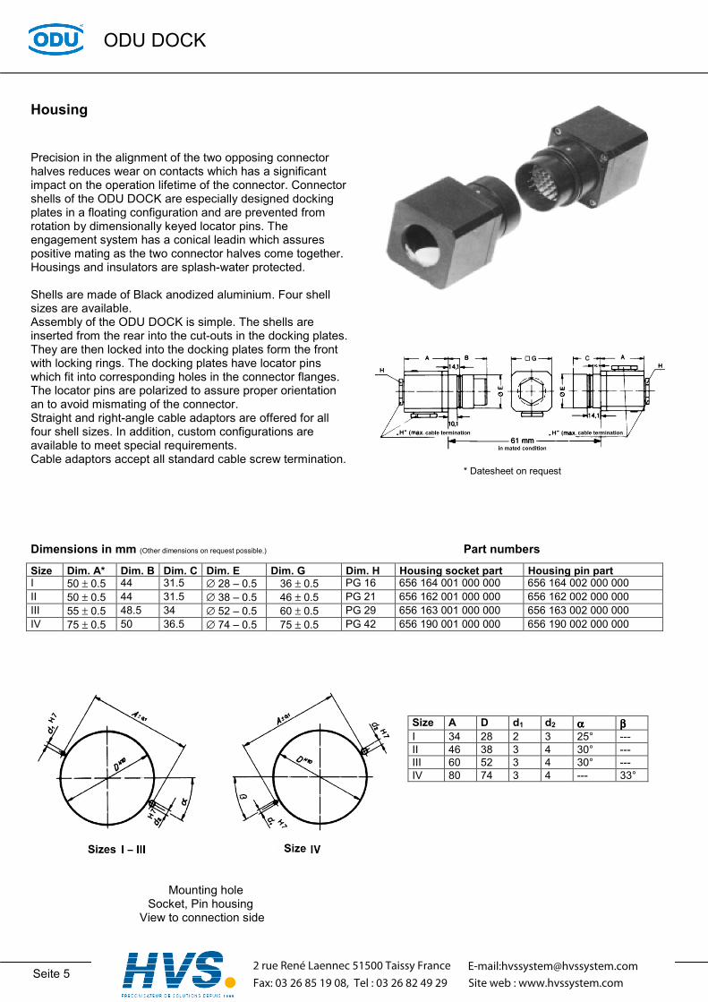
Housing
Precision in the alignment of the two opposing connector halves reduces wear on contacts which has a significant impact on the operation lifetime of the connector. Connector shells of the ODU DOCK are especially designed docking plates in a floating configuration and are prevented from rotation by dimensionally keyed locator pins. The engagement system has a conical leadin which assures positive mating as the two connector halves come together. Housings and insulators are splash-water protected. Shells are made of Black anodized aluminium. Four shell sizes are available. Assembly of the ODU DOCK is simple. The shells are inserted from the rear into the cut-outs in the docking plates. They are then locked into the docking plates form the front with locking rings. The docking plates have locator pins which fit into corresponding holes in the connector flanges. The locator pins are polarized to assure proper orientation an to avoid mismating of the connector. Straight and right-angle cable adaptors are offered for all four shell sizes. In addition, custom configurations are available to meet special requirements. Cable adaptors accept all standard cable screw termination. Dimensions in mm (Other dimensions on request possible.) Size Dim. A* Dim. B Dim. C Dim. E Dim. G DimI 50 ± 0.5 44 31.5 ∅ 28 – 0.5 36 ± 0.5 PG II 50 ± 0.5 44 31.5 ∅ 38 – 0.5 46 ± 0.5 PG III 55 ± 0.5 48.5 34 ∅ 52 – 0.5 60 ± 0.5 PG IV 75 ± 0.5 50 36.5 ∅ 74 – 0.5 75 ± 0.5 PG
Mounting hole
Socket, Pin housing View to connection side
2 rue René Laennec 51Fax: 03 26 85 19 08, Te
– 84453 Mühldorf/Inn, Tel.: +49/8631/6156-0, Fax: +49/8631/6156-49, www.odu.de
* Datesheet on request
Part numbers
. H Housing socket part Housing pin part 16 656 164 001 000 000 656 164 002 000 000 21 656 162 001 000 000 656 162 002 000 000 29 656 163 001 000 000 656 163 002 000 000 42 656 190 001 000 000 656 190 002 000 000
Size A D d1 d2 αααα ββββ I 34 28 2 3 25° --- II 46 38 3 4 30° --- III 60 52 3 4 30° --- IV 80 74 3 4 --- 33°
500 Taissy Francel : 03 26 82 49 29
E-mail:[email protected] web : www.hvssystem.com
ODU DOCK
Seite 6 ODU Steckverbindungssysteme GmbH & Co. KG, Pregelstraße 11, D – 84453 Mühldorf/Inn, Tel.: +49/8631/6156-0, Fax: +49/8631/6156-49, www.odu.de
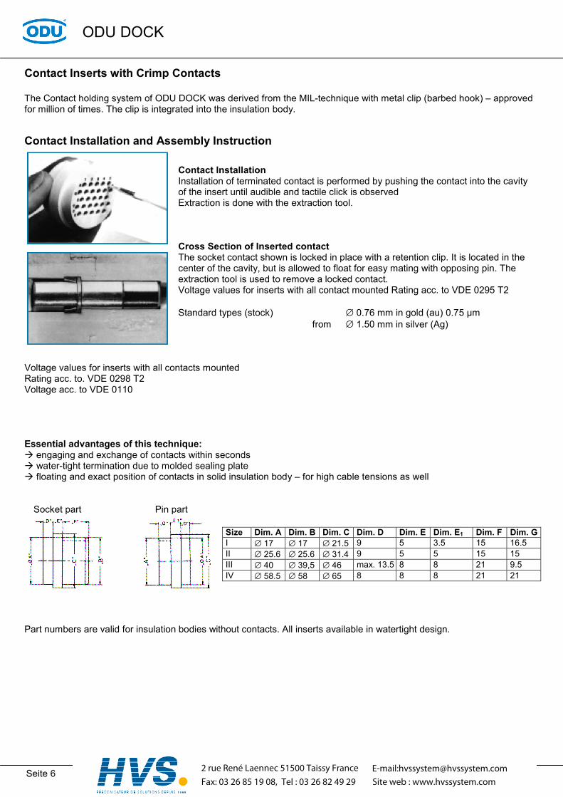
Contact Inserts with Crimp Contacts
The Contact holding system of ODU DOCK was derived from the MIL-technique with metal clip (barbed hook) – approved for million of times. The clip is integrated into the insulation body.
Contact Installation and Assembly Instruction
Contact Installation Installation of terminated contact is performed by pushing the contact into the cavity of the insert until audible and tactile click is observed Extraction is done with the extraction tool. Cross Section of Inserted contact The socket contact shown is locked in place with a retention clip. It is located in the center of the cavity, but is allowed to float for easy mating with opposing pin. The extraction tool is used to remove a locked contact. Voltage values for inserts with all contact mounted Rating acc. to VDE 0295 T2 Standard types (stock) ∅ 0.76 mm in gold (au) 0.75 µm from ∅ 1.50 mm in silver (Ag)
Voltage values for inserts with all contacts mounted Rating acc. to. VDE 0298 T2 Voltage acc. to VDE 0110 Essential advantages of this technique:
engaging and exchange of contacts within seconds water-tight termination due to molded sealing plate floating and exact position of contacts in solid insulation body – for high cable tensions as well
Socket part Pin part
Part numbers are valid for insulation bodies without contacts. All inserts available in watertight design.
Size Dim. A Dim. B Dim. C Dim. D Dim. E Dim. E1 Dim. F Dim. GI ∅ 17 ∅ 17 ∅ 21.5 9 5 3.5 15 16.5 II ∅ 25.6 ∅ 25.6 ∅ 31.4 9 5 5 15 15 III ∅ 40 ∅ 39,5 ∅ 46 max. 13.5 8 8 21 9.5 IV ∅ 58.5 ∅ 58 ∅ 65 8 8 8 21 21
2 rue René Laennec 51500 Taissy FranceFax: 03 26 85 19 08, Tel : 03 26 82 49 29
E-mail:[email protected] web : www.hvssystem.com
ODU DOCK
Seite 7 ODU Steckverbindungssysteme GmbH & Co. KG, Pregelstraße 11, D – 84453 Mühldorf/Inn, Tel.: +49/8631/6156-0, Fax: +49/8631/6156-49, www.odu.de
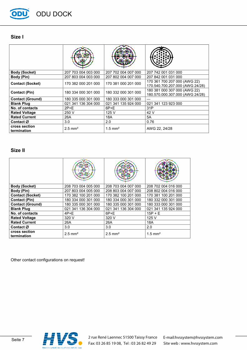
Size I
Body (Socket) 207 703 004 003 000 207 702 004 007 000 207 742 001 031 000 Body (Pin) 207 803 004 003 000 207 802 004 007 000 207 842 001 031 000
Contact (Socket) 170 382 000 201 000 170 381 000 201 000 170 361 700 207 000 (AWG 22) 170.540.700.207.000 (AWG 24/28)
Contact (Pin) 180 334 000 301 000 180 332 000 301 000 180 381 000 307 000 (AWG 22) 180.570.000.307.000 (AWG 24/28)
Contact (Ground) 180 335 000 301 000 180 333 000 301 000 --- Blank Plug 021 341 136 304 000 021 341 135 924 000 021 341 123 923 000 No. of contacts 2P+E 6P+E 31P Rated Voltage 250 V 125 V 42 V Rated Current 26A 18A 5A Contact ∅∅∅∅ 3.0 2.0 0.76 cross section termination 2.5 mm² 1.5 mm² AWG 22, 24/28
Size II
Body (Socket) 208 703 004 005 000 208 703 004 007 000 208 702 004 016 000 Body (Pin) 207 803 004 005 000 208 803 004 007 000 208 802 004 016 000 Contact (Socket) 170 382 100 201 000 170 382 100 201 000 170 381 100 201 000 Contact (Pin) 180 334 000 301 000 180 334 000 301 000 180 332 000 301 000 Contact (Ground) 180 335 000 301 000 180 335 000 301 000 180 333 000 301 000 Blank Plug 021 341 136 304 000 021 341 136 304 000 021 341 135 924 000 No. of contacts 4P+E 6P+E 15P + E Rated Voltage 320 V 320 V 125 V Rated Current 26A 26A 18A Contact ∅∅∅∅ 3.0 3.0 2.0 cross section termination 2.5 mm² 2.5 mm² 1.5 mm²
Other contact configurations on request!
2 rue René Laennec 51500 Taissy FranceFax: 03 26 85 19 08, Tel : 03 26 82 49 29
E-mail:[email protected] web : www.hvssystem.com

ODU DOCK
Seite 8 ODU Steckverbindungssysteme GmbH & Co. KG, Pregelstraße 11, D – 84453 Mühldorf/Inn, Tel.: +49/8631/6156-0, Fax: +49/8631/6156-49, www.odu.de
Size III
Body (Socket) 209 705 004 007 000 209 745 004 027 000 209 703 004 014 000 Body (Pin) 209 805 004 007 000 209 845 004 027 000 209 803 004 014 000 Contact (Socket) 170 633 100 201 000 170 370 000 201 000 172 918 100 201 000 Contact (Pin) 180 633 000 301 000 181 134 000 301 000 181 138 000 301 000 Ground Contact (Pin) --- 181 135 000 301 000 --- Ground Contact (Socket) 170 634 100 201 000 --- 172 919 100 201 000 Blank Plug (Socket) 021 341 141 924 000 021 341 131 923 000 021 341 137 300 000 Blank Plug (Pin) 021 341 142 924 000 021 341 132 923 000 021 341 138 300 000 No. of contacts 6P+E 26P+E 13P + E Rated Voltage 380 V 250 V 300 V Rated Current 65A 18A 18A Contact ∅∅∅∅ 5.0 1.5 3.0 cross section of termination
10 mm² 1.5 mm² 2.5 mm²
Body (Socket) 209 745 004 037 000 209 706 004 003 000 Body (Pin) 209 845 004 037 000 209 806 004 003 000 Contact (Socket) 170 370 000 201 000 172 929 100 201 000 Contact (Pin) 181 134 000 301 000 181 146 000 301 000 Ground Contact (Pin) 181 135 000 301 000 --- Ground Contact (Socket) --- 172 930 100 201 000 Blank Plug (Socket) 021 341 131 923 000 --- Blank Plug (Pin) 021 341 132 923 000 --- No. of contacts 36P+E 2P+E Rated Voltage 250 V 500 V Rated Current 18A 83A Contact ∅∅∅∅ 1.5 6.0 cross section of termination
1.5 mm² 16 mm²
2 rue René Laennec 51500 Taissy FranceFax: 03 26 85 19 08, Tel : 03 26 82 49 29
E-mail:[email protected] web : www.hvssystem.com

ODU DOCK
Seite 9 ODU Steckverbindungssysteme GmbH & Co. KG, Pregelstraße 11, D – 84453 Mühldorf/Inn, Tel.: +49/8631/6156-0, Fax: +49/8631/6156-49, www.odu.de
Crimping tool Termination Cross section (mm)
Contact ∅∅∅∅ in mm
8-point Crimping tools
6-edge Crimping tools
Crimp dies Gauge X
AWG 24/28 0.76 080 000 014 000 000 > 0.65 < 0.70 AWG 22 0.76 080 000 014 000 000 > 0.65 < 0.70. 1.5 mm² 1.5 080 000 014 000 000 > 1.40 < 1.45 1.5 mm² 2.0 080 000 014 000 000
> 1.40 < 1.45 2.5 mm² 3.0 080 000 012 000 000 4.0 mm² 3.0 080 000 011 000 000 6.0 mm² 5.0 080 000 010 000 000
10.0 mm² 5.0 080 000 026 000 000 080 000 026 110 000 16.0 mm² 6.0
080 000 026 000 000 080 000 026 116 000
080 000 014 000 000 080 000 012 000 000 080 000 026 000 000
080 000 011 000 000 080 000 010 000 000
Disassembly tool
Contact ∅∅∅∅ Part-No. 0.76 087 170 361 000 000 1.5 087 170 137 000 000 2.0 087 170 364 000 000 3.0 087 170 136 000 000 5.0 087 170 391 000 000
2 rue René Laennec 51500 Taissy FranceFax: 03 26 85 19 08, Tel : 03 26 82 49 29
E-mail:[email protected] web : www.hvssystem.com

ODU DOCK
Seite 10 ODU Steckverbindungssysteme GmbH & Co. KG, Pregelstraße 11, D – 84453 Mühldorf/Inn, Tel.: +49/8631/6156-0, Fax: +49/8631/6156-49, www.odu.de
Quick-Change-Head
Size I
Size II
Size II
Size III
Size III Part A 252 087 001 007 000 252 080 001 007 000 252 080 001 016 000 252 058 002 027 000 252 058 001 037 000 Part B 252 089 001 007 000 252 082 001 107 000 252 082 001 016 000 252 061 002 027 000 252 061 001 037 000 Part C 252 088 001 007 000 252 081 001 007 000 252 081 001 016 000 252 059 002 027 000 252 059 001 037 000 Part D 252 089 002 007 000 252 082 001 107 000 252 082 002 016 000 252 061 003 027 000 252 061 002 037 000 No. of contacts 6P+E 6P+E 15P+E 26P+E 36P+E Rated voltage 50 V 250 V 40 V 100 V 63 V Rated current 18A 18A 18A 16A 16A Contact ∅∅∅∅ 2.0 mm 3.0 mm 2.0 mm 1.5 mm 1.5 mm Term. Cross section
0.5 – 1.5 mm² 0.5 – 1.5 mm² 0.5 – 1.5 mm² 0.5 – 1.5 mm² 0.5 – 1.5 mm²
2 rue René Laennec 51500 Taissy FranceFax: 03 26 85 19 08, Tel : 03 26 82 49 29
E-mail:[email protected] web : www.hvssystem.com

ODU DOCK
Seite 11 ODU Steckverbindungssysteme GmbH & Co. KG, Pregelstraße 11, D – 84453 Mühldorf/Inn, Tel.: +49/8631/6156-0, Fax: +49/8631/6156-49, www.odu.de
Quick-Change-Head Crimping Tools
080 000 038 000 000 080 000 014 000 000 Termination Cross Section
Crimp Tool Stripping length
080 000 038 000 000
080 000 014 000 000
mm²
AWG
Position Adjustment ∅∅∅∅
Positioner for 080 000 014 000 000
mm
0.5 20 4 > 1.05 < 1.10 0.75 1 18 5 > 1.10 < 1.15
1.5 14 6 > 1.40 < 1.45
021 345 161 300 000
6 +0.5
Assembly tool Part-No.: 085 170 323 000 000 Disassembly tool Part-No.: 087 170 323 000 000
2 rue René Laennec 51500 Taissy FranceFax: 03 26 85 19 08, Tel : 03 26 82 49 29
E-mail:[email protected] web : www.hvssystem.com

ODU DOCK
Seite 12 ODU Steckverbindungssysteme GmbH & Co. KG, Pregelstraße 11, D – 84453 Mühld
Contact Inserts with Solder-In Contacts Number of contacts 2-68 Rated Current 10 A – 83 A Rated Voltage to 500 V/C~ Contact Carrier: glassfibre reinforced Polyester Contacts: Cu-Alloy nickeled resp. silver-plated with solder termination Size I
Socket 656 164 703 152 003 656 164 702 150 003 656 164 745 751 0Pin 656 164 803 152 003 656 164 802 150 003 656 164 845 751 0No. of contacts 2P+E 2P+E 2P Rated Voltage 250 V/C~ 250 V/C~ 415 V/C~ Rated Current 26A 26A 10A Contact ∅∅∅∅ 3.0 2.0 1.5 cross section of termination
2.5 mm² 2.5 mm² 2.5 mm²
Socket 656 164 702 150 004 656 164 702 150 005 656 164 702 152 0Pin 656 164 802 150 004 656 164 802 150 005 656 164 802 150 0No. of contacts 3P+E 4P+E 6P+E Rated Voltage 250 V/C~ 250 V/B~ 250 V/B~ Rated Current 26A 18A 18A Contact ∅∅∅∅ 2 2 2 cross section of termination
2.5 mm² 1.5 mm² 1.5 mm²
2 rue René Laennec 51500 Taissy FFax: 03 26 85 19 08, Tel : 03 26 82
orf/Inn, Tel.: +49/8631/6156-0, Fax: +49/8631/6156-49, www.odu.de
02 656 164 745 751 004 656 164 745 751 006 02 656 164 845 751 004 656 164 845 751 006
4P 6P 415 V/C~ 380 V/C~ 10A 10A 1.5 1.5 2.5 mm² 2.5 mm²
07 656 164 701 150 010 07 656 164 801 150 010
9P+E 125 V/C~ 10A 1 1.0 mm²
rance49 29
E-mail:[email protected] web : www.hvssystem.com

ODU DOCK
Seite 13 ODU Steckverbindungssysteme GmbH & Co. KG, Pregelstraße 11, D – 84453 Mühldorf/Inn, Tel.: +49/8631/6156-0, Fax: +49/8631/6156-49, www.odu.de
Contact Inserts with Solder-In Contacts Size II
Socket 656 162 705 150 003 656 162 703 152 005 656 162 703 161 007 656 162 702 153 016 Pin 656 162 805 150 003 656 162 803 152 005 656 162 803 161 007 656 162 802 153 016 No. of contacts 2P+E 4P+E 6P+E 15P+E Rated Voltage 250V/C~ 380V/C~ 380V/C~ 250V/C~ Rated Current 65A 26A 26A 18A Contact ∅∅∅∅ 5.0 3.0 3.0 2.0 cross section of termination
10 mm² 2.5 mm² 2.5 mm² 1.5 mm²
Socket 656 162 745 150 012 656 162 701 150 024 656 162 704 150 005 656 162 745 150 010 Pin 656 162 845 150 012 656 162 801 150 024 656 162 804 150 005 656 162 845 150 010 No. of contacts 11P+E 23P+E 4P+E 9P+E Rated Voltage 250V/C~ 125V/C~ 250V/C~ 250V/C~ Rated Current 12A 16A 47A 12A Contact ∅∅∅∅ 1.5 1.0 4.0 1.5 cross section of termination
0.75 mm² 1.5 mm² 6.0 mm² 0.75 mm²
2 rue René Laennec 51500 Taissy FranceFax: 03 26 85 19 08, Tel : 03 26 82 49 29
E-mail:[email protected] web : www.hvssystem.com
ODU DOCK
Seite 14 ODU Steckverbindungssysteme GmbH & Co. KG, Pregelstraße 11, D – 84453 Mühldorf/Inn, Tel.: +49/8631/6156-0, Fax: +49/8631/6156-49, www.odu.de
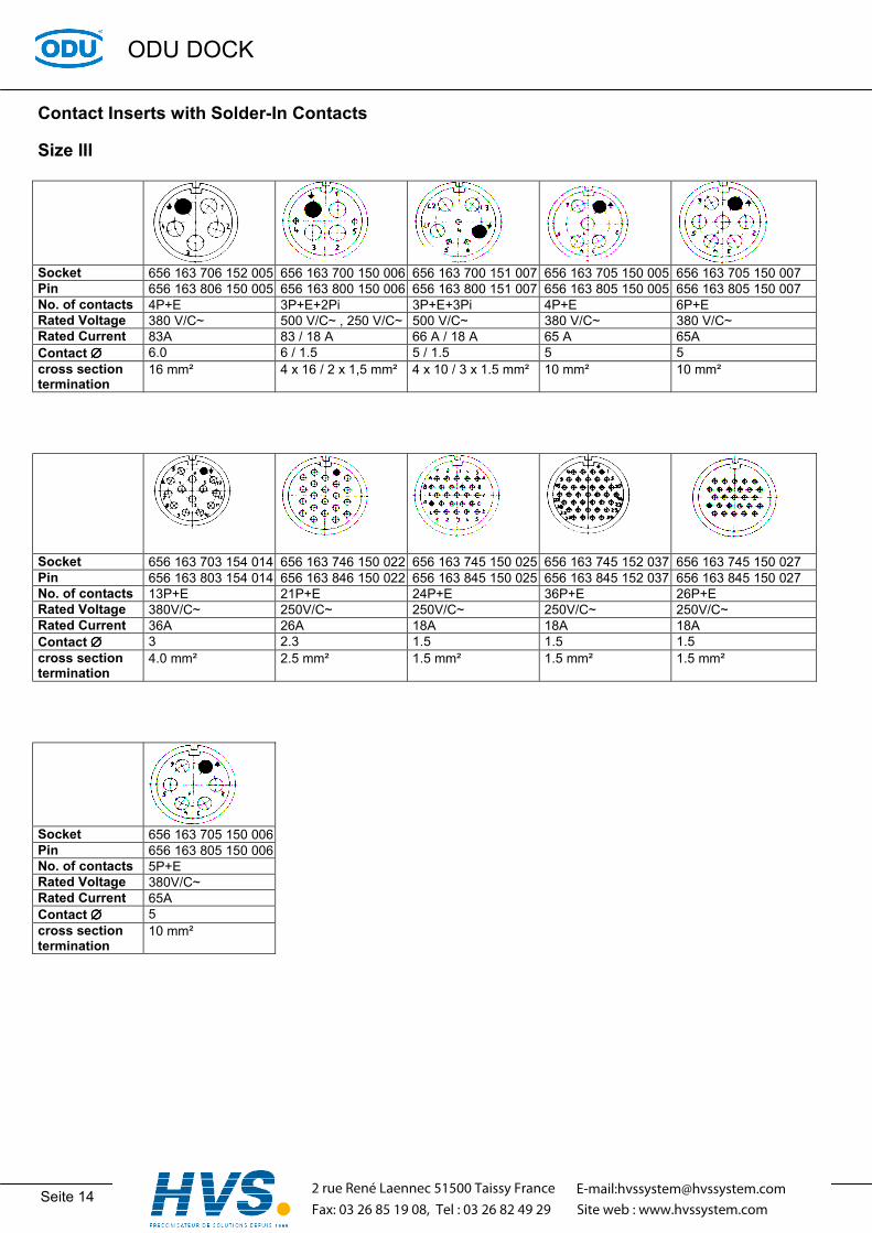
Contact Inserts with Solder-In Contacts Size III
Socket 656 163 706 152 005 656 163 700 150 006 656 163 700 151 007 656 163 705 150 005 656 163 705 150 007 Pin 656 163 806 150 005 656 163 800 150 006 656 163 800 151 007 656 163 805 150 005 656 163 805 150 007 No. of contacts 4P+E 3P+E+2Pi 3P+E+3Pi 4P+E 6P+E Rated Voltage 380 V/C~ 500 V/C~ , 250 V/C~ 500 V/C~ 380 V/C~ 380 V/C~ Rated Current 83A 83 / 18 A 66 A / 18 A 65 A 65A Contact ∅∅∅∅ 6.0 6 / 1.5 5 / 1.5 5 5 cross section termination
16 mm² 4 x 16 / 2 x 1,5 mm² 4 x 10 / 3 x 1.5 mm² 10 mm² 10 mm²
Socket 656 163 703 154 014 656 163 746 150 022 656 163 745 150 025 656 163 745 152 037 656 163 745 150 027 Pin 656 163 803 154 014 656 163 846 150 022 656 163 845 150 025 656 163 845 152 037 656 163 845 150 027 No. of contacts 13P+E 21P+E 24P+E 36P+E 26P+E Rated Voltage 380V/C~ 250V/C~ 250V/C~ 250V/C~ 250V/C~ Rated Current 36A 26A 18A 18A 18A Contact ∅∅∅∅ 3 2.3 1.5 1.5 1.5 cross section termination
4.0 mm² 2.5 mm² 1.5 mm² 1.5 mm² 1.5 mm²
Socket 656 163 705 150 006 Pin 656 163 805 150 006 No. of contacts 5P+E Rated Voltage 380V/C~ Rated Current 65A Contact ∅∅∅∅ 5 cross section termination
10 mm²
2 rue René Laennec 51500 Taissy FranceFax: 03 26 85 19 08, Tel : 03 26 82 49 29
E-mail:[email protected] web : www.hvssystem.com

ODU DOCK
Seite 15 ODU Steckverbindungssysteme GmbH & Co. KG, Pregelstraße 11, D – 84453 Mühldorf/Inn, Tel.: +49/8631/6156-0, Fax: +49/8631/6156-49, www.odu.de
For your notes:
2 rue René Laennec 51500 Taissy FranceFax: 03 26 85 19 08, Tel : 03 26 82 49 29
E-mail:[email protected] web : www.hvssystem.com
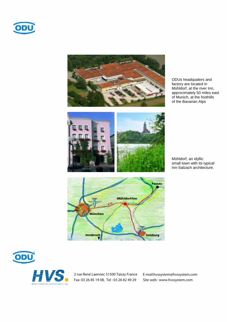
ODUs headquaters and factory are located in Mühldorf, at the river Inn, approcimately 50 miles east of Munich, at the foothills of the Bavarian Alps Mühldorf, an idyllic small town with its typical Inn-Salzach architecture.
2 rue René Laennec 51500 Taissy FranceFax: 03 26 85 19 08, Tel : 03 26 82 49 29
E-mail:[email protected] web : www.hvssystem.com
Related Documents