The ODOT User Guide for AutoTable October 19, 2012 Sheet 1 of 25 Table of Contents Introduction........................................................................................................................................2 What is AutoTable and Why Do We Want to Use It? ..........................................................................2 Content ...........................................................................................................................................2 Additional Resources ........................................................................................................................2 Installation and Licensing ....................................................................................................................3 Step-By-Step ...................................................................................................................................3 Before you start ...........................................................................................................................3 Installation...................................................................................................................................3 User Standards Setup ...................................................................................................................3 Activation and Settings ........................................................................................................................4 Activation ........................................................................................................................................4 ODOT Standards..............................................................................................................................4 Font Mapping ..................................................................................................................................4 General........................................................................................................................................4 “Default” Dialog: Font Mapping Area ............................................................................................6 “Default” Dialog: Override Font Area .............................................................................................7 “Specific” Dialog: Font Map Display Area........................................................................................8 “Specific” Dialog: Font Control Area ...............................................................................................8 Excel Features .................................................................................................................................9 General........................................................................................................................................9 Border Weights/Line Styles ...........................................................................................................9 Fonts ......................................................................................................................................... 10 Patterns ..................................................................................................................................... 10 Cell Shading ............................................................................................................................... 10 Excel Auto Table Options ............................................................................................................... 11 General...................................................................................................................................... 11 Buttons ...................................................................................................................................... 11 Layer & Color Tab ...................................................................................................................... 11 Scale Tab................................................................................................................................... 12 Object and Font Map Tab ........................................................................................................... 13 Other Tab .................................................................................................................................. 14 Using AutoTable................................................................................................................................ 15 MicroStation Toolbar ...................................................................................................................... 15 Create AutoTable ....................................................................................................................... 15 Edit AutoTable ........................................................................................................................... 16 Update AutoTable ...................................................................................................................... 16 Help .......................................................................................................................................... 16 Excel Toolbar ................................................................................................................................ 17 Finish ........................................................................................................................................ 17 Range Import............................................................................................................................. 17 AutoTable Options ...................................................................................................................... 18 AutoTable Help .......................................................................................................................... 18 Cadig Menu................................................................................................................................ 18 Plan Sheet Design ............................................................................................................................. 21 Recommendations/Limitations ........................................................................................................... 24 Trademarks ...................................................................................................................................... 25 Contact Information: ......................................................................................................................... 25

Welcome message from author
This document is posted to help you gain knowledge. Please leave a comment to let me know what you think about it! Share it to your friends and learn new things together.
Transcript

The ODOT User Guide for AutoTable
October 19, 2012 Sheet 1 of 25
Table of Contents
Introduction........................................................................................................................................ 2
What is AutoTable and Why Do We Want to Use It? .......................................................................... 2 Content ........................................................................................................................................... 2 Additional Resources ........................................................................................................................ 2
Installation and Licensing .................................................................................................................... 3 Step-By-Step ................................................................................................................................... 3
Before you start ........................................................................................................................... 3 Installation ................................................................................................................................... 3 User Standards Setup ................................................................................................................... 3
Activation and Settings ........................................................................................................................ 4 Activation ........................................................................................................................................ 4 ODOT Standards.............................................................................................................................. 4 Font Mapping .................................................................................................................................. 4
General........................................................................................................................................ 4 “Default” Dialog: Font Mapping Area ............................................................................................ 6 “Default” Dialog: Override Font Area ............................................................................................. 7 “Specific” Dialog: Font Map Display Area ........................................................................................ 8 “Specific” Dialog: Font Control Area ............................................................................................... 8
Excel Features ................................................................................................................................. 9 General........................................................................................................................................ 9 Border Weights/Line Styles ........................................................................................................... 9 Fonts ......................................................................................................................................... 10 Patterns ..................................................................................................................................... 10 Cell Shading ............................................................................................................................... 10
Excel Auto Table Options ............................................................................................................... 11 General...................................................................................................................................... 11 Buttons ...................................................................................................................................... 11 Layer & Color Tab ...................................................................................................................... 11 Scale Tab ................................................................................................................................... 12 Object and Font Map Tab ........................................................................................................... 13 Other Tab .................................................................................................................................. 14
Using AutoTable................................................................................................................................ 15 MicroStation Toolbar ...................................................................................................................... 15
Create AutoTable ....................................................................................................................... 15 Edit AutoTable ........................................................................................................................... 16 Update AutoTable ...................................................................................................................... 16 Help .......................................................................................................................................... 16
Excel Toolbar ................................................................................................................................ 17 Finish ........................................................................................................................................ 17 Range Import............................................................................................................................. 17 AutoTable Options ...................................................................................................................... 18 AutoTable Help .......................................................................................................................... 18 Cadig Menu ................................................................................................................................ 18
Plan Sheet Design ............................................................................................................................. 21 Recommendations/Limitations ........................................................................................................... 24 Trademarks ...................................................................................................................................... 25 Contact Information: ......................................................................................................................... 25

The ODOT User Guide for AutoTable
October 19, 2012 Sheet 2 of 25
Introduction
What is AutoTable and Why Do We Want to Use It?
AutoTable is a software product from CADIG Inc. that imports Excel worksheets into
MicroStation design files as native MicroStation elements and allows the imported
information to be easily updated when changes have been made in the original Excel files.
The Excel elements that can be imported and updated include text, tables/cell borders,
charts, cell shading, images, and some Excel AutoShapes. AutoTable provides options that
allow the user considerable control over the translation of the Excel elements to
MicroStation elements (e.g. symbology, font style and type, scale).
Also of note: due to the nature of the AutoTable link between a MicroStation representation
of an Excel file and the actual Excel file, the product does allow a user in a MicroStation file
to update an imported Excel table at the same time another user is in the original Excel file.
Content
This document will attempt to give users (and CADD administrators) the “How To” when
using AutoTable for the first time. The following general topics are covered:
Installation/Licensing
Activation and Settings
Using AutoTable
Plan Sheet Design
Recommendations/Limitations
Some information in this documentation has been taken directly from the AutoTable Help.
Additional Resources
A brief demo on the use of AutoTable is available at the website link shown below.
http://www.cadig.com/demo/at/
Although the demo uses AutoCAD as an example, please be aware that any and all options
shown for AutoCAD are also provided for MicroStation in the current release.
A small on-line tutorial has also been prepared by the Office of CADD and Mapping Services
and is located under “Training Modules” at the website link shown below:
http://www.dot.state.oh.us/Divisions/Engineering/CADDMapping/CADD/Pages/AutoTable.aspx

The ODOT User Guide for AutoTable
October 19, 2012 Sheet 3 of 25
Installation and Licensing
Step-By-Step
Before you start
Before installing AutoTable v3.7.0.0, you should uninstall any previous versions of the
software.
You must also make sure that you have the ODOT Standard Cadig sub-directory in your
ODOTstd/V8istd directory; you may copy it from \\itcfs007\idrive\ODOTstd\V8istd\Cadig\.
This directory contains ODOT’s Standard Excel Sheets, our AutoTable Standards, any vba
programs/add-ins used to run our automated spreadsheet programs, and this
documentation. The Standards files are ODOT Standard Fonts.afm, ODOT AutoTable
Options.opt, and As Delivered Options.opt. The file As Delivered Options.opt can be used to
quickly return the AutoTable Excel options back to their original delivered state. There is
also a batch file, AutoTableSetup_v8i.bat, for each user to run once on their particular
computer that loads all of the ODOT standards for AutoTable.
Installation
You must have administrator privileges to perform the installation.
The AutoTable software is found in the sub-directory \\itcfs007\support1\Win7Software -
PC\AutoTable\V8i. The Installation of AutoTable occurs as part of the Bentley V8i Suite
installation. If a manual installation is necessary, run setup.exe from the above directory
and accept the defaults. After installation, license activation can be loaded by registry key.
Use License_AMD64.reg from the above folder, (or License.reg for a 32-bit OS).
User Standards Setup
The software installation is now complete and the AutoTable Standards setup is next.
The Administrator should now log out and allow the user to login and complete the following
Step.
The Excel AutoTable Standards is required and must be loaded once by each user on the
machine. Run file AutoTableSetup_v8i.bat, located in the ODOTstd\V8istd\Cadig\AutoTable
Standards directory, to load the necessary ODOT user standards.

The ODOT User Guide for AutoTable
October 19, 2012 Sheet 4 of 25
Activation and Settings
Activation
When a MicroStation design file is opened, a Cadig pull-down should appear on the main
toolbar menu. This Cadig pull-down menu contains additional features that are not
accessible in the accompanying MicroStation AutoTable toolbar.
Figure 2 shows the MicroStation AutoTable toolbar that appears on the screen after opening
a design file. When the Create AutoTable or the Edit AutoTable command is issued from
either this toolbar or the Cadig pull-down menu, an Excel AutoTable toolbar, as shown in
Figure 3, will appear in the Excel worksheet. These toolbars are fully explained in the Using
AutoTable section of this document.
Figure 2
Toolbar in MicroStation
Figure 3
Toolbar in Excel
ODOT Standards
The standards mentioned in the Installation/Licensing section should have been loaded
immediately after the AutoTable installation; if not, please execute the instructions in the
User Standards Setup section now.
The standards affect font type and placement Level, Scale, Rotation Angle, etc. for new and
existing AutoTable imports. They may be viewed/modified from either of two dialog boxes;
one accessible from MicroStation and the other from Excel.
Font Mapping
General
Font Mapping allows the user to specify, or “map”, a specific Excel font to a specific
MicroStation font. For example, as per the ODOT standard, when Arial Regular is used in
Excel it is placed as Font 30 in MicroStation.
The “default” Font Map dialog, as shown in Figure 4 below, is accessed from MicroStation by
selecting Cadig>AutoTable>Font Map from the menu bar or by entering the key-in:
autotable fontmap. There is no access to the dialog from Excel.

The ODOT User Guide for AutoTable
October 19, 2012 Sheet 5 of 25
The term “default” is used to
differentiate the font mapping that is
to be used, in general, for all Excel
imports, from the mapping that may
be necessary for a “specific” import.
The import-specific version of the
same dialog, as shown below in Figure
5, will be displayed before an import
may be placed/updated, provided the
“Show the font map dialog when
creating table” option is checked on,
as shown to the left.
The settings as displayed in Figure 4
are the ODOT standard default
settings. They are to be used for all
highway and bridge plan work that
may possibly be modified by another
District/Office.
The import-specific Font Map dialog
tells you what fonts were found in the
Excel table being imported/updated
and allows various options for
translating them into MicroStation
fonts and associated text elements.
Note that both versions allow you to
save your font map to a file, or to load
a font map from a saved file.
It is important to understand that the
active text settings of the design file
are not used by AutoTable when
placing or updating a table (Text
Height, Width, and Justification, and
the Annotation Scale); these properties
are instead determined by the Excel
Worksheet and the settings in the
Excel AutoTable Options.
If there is no font map in use, all
imported fonts will be placed in the
active font of the design file.
The dialog boxes shown in Figures 4
and 5 are comprised, for purposes of
this documentation, of two functional
sections: a font mapping area (the
upper portion of the dialog) and a font
override/control area (the lower
section). The following sections
describe the functioning of each area,
Figure 4 “Default” Font Map dialog box
Figure 5 “Specific” Font Map dialog box

The ODOT User Guide for AutoTable
October 19, 2012 Sheet 6 of 25
for each version of the dialog, in detail.
“Default” Dialog: Font Mapping Area
The Font Mapping Area allows the user to pre-set the translation of specific TrueType fonts
used in Excel to specific MicroStation fonts. For example, in Figure 6 below, Arial Regular is
to be placed as Font 30 in MicroStation. This section allows the user to modify/create the
mapped fonts using the Add, Remove, Save to file, and Load from file buttons.
Figure 6
The buttons and drop-down lists shown in Figure 6 are used in the following manner:
Add
This feature allows the user to add a “mapping” of a TrueType font to a MicroStation font.
The TrueType font name and style is selected along with the MicroStation font from the drop
downs lists at the top of the dialog. Then, click on the “Add” button to add your selections
to the display list. Note that the drop downs correspond to the column headers in the
display list – the left-most two boxes (Font Name, Font Style) describe the “from” (Excel)
font, and the right-most box (Font in MicroStation) describes the “to” (MicroStation) font.
Remove
To remove a font mapping from the display list, select the mapping and click on the
“Remove” button.
Save to file
To save the currently displayed font mappings to a file, click on the “Save to file” button.
Load from file
To load a previously saved font mapping, click on the “Load from file” button, then, in the
resulting file open dialog, navigate to the desired subdirectory and file to make your
selection.

The ODOT User Guide for AutoTable
October 19, 2012 Sheet 7 of 25
“Default” Dialog: Override Font Area
This section of the dialog contains three toggles, as shown in Figure 7, below. The top-most
toggle controls whether or not the design file’s “Active Font”, or a font selected from the
available drop-down list, will be allowed to override the font-mapping displayed in the upper
part of the dialog. The middle toggle controls the weight at which any Bold TrueType fonts
shown in the Font Map dialog box will display in MicroStation. The last toggle controls
whether or not the import-specific version of the Font Map dialog box (Figure 5), will display
before an Excel import can be placed/updated.
Figure 7
(Note that the figure shows the toggles’ settings as per ODOT’s recommended practice for
AutoTable.
When option “Use the same font for all fonts” is toggled on, the font mapping area shown in
the upper portion of the dialog is grayed out (made inactive) and the font selection drop-
down list to the right of the toggle becomes active. The font selected from the drop-down
will override the font map settings in all table placements until such time as the option is
toggled off or, for a specific import/update, the user chooses to ignore the override via
his/her selections in the import-specific version of the Font Map dialog (see the next
section).
To control the weight at which “Bold” TrueType fonts are placed in MicroStation, the user
should toggle on the “Line weight for bold style” option. This option is primarily for use with
table header text that may be larger than normal text. When toggled on, the key-in field
becomes active, allowing the user to enter the desired weight. The TrueType fonts that will
use this weight setting will be shown in the “Font Style” column of the display area of the
dialog.
When the option “Show the font map dialog when creating table” is checked on, the
“import-specific” version of the Font Map dialog box (see Figure 5), will be displayed before
the user is allowed to place or update an Excel table in a design file.
The ODOT User Guide for AutoTable
October 19, 2012 Sheet 8 of 25
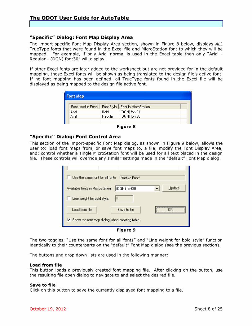
“Specific” Dialog: Font Map Display Area
The import-specific Font Map Display Area section, shown in Figure 8 below, displays ALL
TrueType fonts that were found in the Excel file and MicroStation font to which they will be
mapped. For example, if only Arial normal is used in the Excel table then only “Arial -
Regular - (DGN) font30” will display.
If other Excel fonts are later added to the worksheet but are not provided for in the default
mapping, those Excel fonts will be shown as being translated to the design file’s active font.
If no font mapping has been defined, all TrueType fonts found in the Excel file will be
displayed as being mapped to the design file active font.
Figure 8
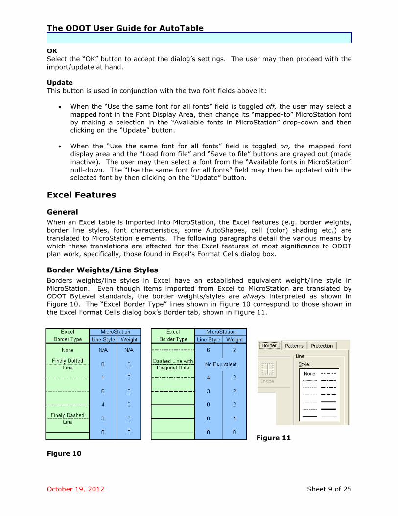
“Specific” Dialog: Font Control Area
This section of the import-specific Font Map dialog, as shown in Figure 9 below, allows the
user to: load font maps from, or save font maps to, a file; modify the Font Display Area,
and; control whether a single MicroStation font will be used for all text placed in the design
file. These controls will override any similar settings made in the “default” Font Map dialog.
Figure 9
The two toggles, “Use the same font for all fonts” and “Line weight for bold style” function
identically to their counterparts on the “default” Font Map dialog (see the previous section).
The buttons and drop down lists are used in the following manner:
Load from file
This button loads a previously created font mapping file. After clicking on the button, use
the resulting file open dialog to navigate to and select the desired file.
Save to file
Click on this button to save the currently displayed font mapping to a file.
The ODOT User Guide for AutoTable
October 19, 2012 Sheet 9 of 25
OK
Select the “OK” button to accept the dialog’s settings. The user may then proceed with the
import/update at hand.
Update
This button is used in conjunction with the two font fields above it:
When the “Use the same font for all fonts” field is toggled off, the user may select a
mapped font in the Font Display Area, then change its “mapped-to” MicroStation font
by making a selection in the “Available fonts in MicroStation” drop-down and then
clicking on the “Update” button.
When the “Use the same font for all fonts” field is toggled on, the mapped font
display area and the “Load from file” and “Save to file” buttons are grayed out (made
inactive). The user may then select a font from the “Available fonts in MicroStation”
pull-down. The “Use the same font for all fonts” field may then be updated with the
selected font by then clicking on the “Update” button.
Excel Features
General
When an Excel table is imported into MicroStation, the Excel features (e.g. border weights,
border line styles, font characteristics, some AutoShapes, cell (color) shading etc.) are
translated to MicroStation elements. The following paragraphs detail the various means by
which these translations are effected for the Excel features of most significance to ODOT
plan work, specifically, those found in Excel’s Format Cells dialog box.
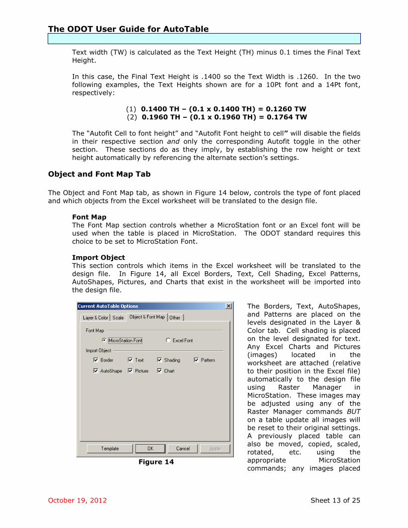
Border Weights/Line Styles
Borders weights/line styles in Excel have an established equivalent weight/line style in
MicroStation. Even though items imported from Excel to MicroStation are translated by
ODOT ByLevel standards, the border weights/styles are always interpreted as shown in
Figure 10. The “Excel Border Type” lines shown in Figure 10 correspond to those shown in
the Excel Format Cells dialog box’s Border tab, shown in Figure 11.
Figure 11
Figure 10

The ODOT User Guide for AutoTable
October 19, 2012 Sheet 10 of 25
An imported line’s color is defined by the design file’s ByLevel setting or the option selected
in the Excel AutoTable Options dialog box.
Fonts
The MicroStation text elements from an imported Excel table will automatically receive some
font features from the Alignment and Font tabs (per the Excel Format Cells dialog box
settings) used with the original table.
MicroStation Font Justification
This is determined by the settings in the Alignment tab i.e. a Horizontal setting of
Center and a Vertical setting of Top will result in a Center-Top justification in
MicroStation. Only the Left (Indent), Center, and Right (Indent) Horizontal settings
should be used. The Horizontal settings of General, Fill, Justify, and Center Across
Selection along with the Justify and Distributed Vertical settings are usable but the
resulting MicroStation justification may vary upon whether text or numbers are used.
Use the recommended settings of Left (Indent), Center, and Right (Indent) for the
Horizontal settings and Top, Center, and Bottom for the Vertical settings.
Underline
This feature is found under the Font tab; only the Single Underline and the Color
selection menu of this tab will be honored in MicroStation.
Font weight is determined by the ByLevel setting of the design file’s active level.
Patterns
All Excel patterns available from the Patterns tab in the Excel Format Cells dialog box are
displayable in MicroStation. The design file level to which a pattern is translated is
determined by the defined level in the Excel AutoTable Options dialog box (see below). The
weight of the lines in the pattern is determined by the pattern itself. Patterns with thin lines
will be placed at a weight of 0, thicker lines will be placed at a weight of 2. A line style code
of 0 is used for a solid line pattern while any dotted or dashed line patterns will display with
a line style code of 1.
Cell Shading
Any cell shading used in the Excel table will also carry over to MicroStation.

The ODOT User Guide for AutoTable
October 19, 2012 Sheet 11 of 25
Excel Auto Table Options
General
The Auto Table Options button on the
Excel AutoTable tool bar (see sheet 17)
opens the Current Auto Table Options
dialog box, as shown in Figure 12. Note
that the dialog will appear with the
caption “Options” prior to being imported
to MicroStation.
This dialog allows the user to set the
desired preferences for translation of
Excel elements and/or features into the
MicroStation design file.
The default settings for the dialog are set
by the ODOT standards loaded by the
user (see User Standards Setup).
The dialog contains four tabs for
controlling the translation of items from
Excel to MicroStation. The tabs are
labeled as “Layer & Color”, “Scale”,
“Object & Font Map”, and “Other”. These tabs will be discussed individually in the following
sub-sections.
Buttons
The Template, OK, Cancel, and Apply buttons, as shown in Figure 12, appear regardless of
the tab selected.
The Template button opens a drop-down list that allows the user to load predetermined
settings from a file, via the “Load from file” selection, or save the current options to a file
using the “Save to file” selection.
The OK and Apply button save any changes made to the options. The OK button closes the
dialog box, as well.
The Cancel button closes the dialog box and ignores any changes.
Layer & Color Tab
The Layer & Color tab, as shown in Figure 12, controls the translation of Excel borders, text,
patterns, and AutoShapes to MicroStation levels and colors.
Level
The Level section controls which MicroStation levels the Excel borders, text, AutoShapes,
and Patterns are to be written too. The user keys in the desired named/numbered level
in the appropriate key-in field. In Figure 12, the table border, AutoShapes (if any), and
Excel AutoTable Options
Figure 12

The ODOT User Guide for AutoTable
October 19, 2012 Sheet 12 of 25
Excel Patterns (if any) are to be translated to level SH_Data and the text is to go to level
SH_Text.
If no levels are defined, the table and its contents are placed on the design file’s active
level.
Border Color and Text Color
The radio buttons in these two sections control the color for all borders and text
imported to the design file. These elements can be placed at the ByLevel, MicroStation
equivalent, or a defined color when the “By Border Lineweight” and “By Font Style”
toggles are used. If the “By Border Lineweight” and/or the “By Font Style” toggles are
checked on, the color drop down lists for “Thin/Thick” borders and “Regular/Bold” text
become active, allowing the user to select the desired colors for borders and text.
Scale Tab
The Scale tab, shown in Figure 13, has two sections; Cell Scale and Text. These sections
control the height of the text and the interline spacing of the rows in the table.
Cell Scale and Text
The “Scale:” and “Custom:” fields represent 1 design file unit (foot) to 1 Excel point.
For example, an Excel row height of 12.75 points at 1:1 would equal a row height of
12.75 feet in MicroStation.
The factors shown in the “Custom:” sections of Figure 13 are designed to give the
user a MicroStation text height of exactly .1400 from an Excel Arial 10Pt, and a row
height of exactly .2800 in MicroStation from an Excel cell height of 12.75 points. The
interline spacing of .2800 was chosen as the standard in order to conform to the
forth-coming row spacing size for all ODOT standard sheets containing charts. If a
larger text size is desired, for, say, a table header, the font point size should be
changed. Acceptable point sizes to use for such purposes are 12Pt, 14Pt and 18Pt.
These sizes provide the closest approximation to the MicroStation text heights of
.1700, .2000, and .2500,
respectively.
The scale factors shown in the figure
have a direct relationship with the
Excel cell height (default 12.75) and
font size (default Arial 10Pt) used in
the worksheet. They are calculated
in the following manner:
Desired MicroStation Interline
Spacing/Excel Row Height = Cell
Scale Factor
0.2800/12.75 = 0.0219608
Desired MicroStation Font
Height/Excel Font Size = Text Scale
Factor
0.1400/10 = 0.014
Figure 13
The ODOT User Guide for AutoTable
October 19, 2012 Sheet 13 of 25
Text width (TW) is calculated as the Text Height (TH) minus 0.1 times the Final Text
Height.
In this case, the Final Text Height is .1400 so the Text Width is .1260. In the two
following examples, the Text Heights shown are for a 10Pt font and a 14Pt font,
respectively:
(1) 0.1400 TH – (0.1 x 0.1400 TH) = 0.1260 TW
(2) 0.1960 TH – (0.1 x 0.1960 TH) = 0.1764 TW
The “Autofit Cell to font height” and “Autofit Font height to cell” will disable the fields
in their respective section and only the corresponding Autofit toggle in the other
section. These sections do as they imply, by establishing the row height or text
height automatically by referencing the alternate section’s settings.
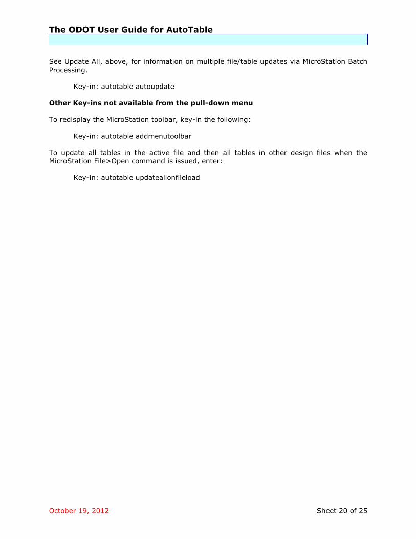
Object and Font Map Tab
The Object and Font Map tab, as shown in Figure 14 below, controls the type of font placed
and which objects from the Excel worksheet will be translated to the design file.
Font Map
The Font Map section controls whether a MicroStation font or an Excel font will be
used when the table is placed in MicroStation. The ODOT standard requires this
choice to be set to MicroStation Font.
Import Object
This section controls which items in the Excel worksheet will be translated to the
design file. In Figure 14, all Excel Borders, Text, Cell Shading, Excel Patterns,
AutoShapes, Pictures, and Charts that exist in the worksheet will be imported into
the design file.
The Borders, Text, AutoShapes,
and Patterns are placed on the
levels designated in the Layer &
Color tab. Cell shading is placed
on the level designated for text.
Any Excel Charts and Pictures
(images) located in the
worksheet are attached (relative
to their position in the Excel file)
automatically to the design file
using Raster Manager in
MicroStation. These images may
be adjusted using any of the
Raster Manager commands BUT
on a table update all images will
be reset to their original settings.
A previously placed table can
also be moved, copied, scaled,
rotated, etc. using the
appropriate MicroStation
commands; any images placed Figure 14

The ODOT User Guide for AutoTable
October 19, 2012 Sheet 14 of 25
with this table will also be moved, copied, scaled, rotated etc. once the table is
updated.
Other Tab
The Other tab, shown in Figure 15, has several key-in fields, a drop-down menu, and a
“Browse” icon. They are used in the following manner:
Rotation Degree:
Defines the rotation of the table
when placed in the design file
(default is 0).
Link Path Type:
This drop-down contains the Full
path, Relative path, and No Path
options. AutoTable uses the Link
Path Type designation to search for
the Excel file’s directory.
The ODOT standard is set to
Relative path. This option is ideal
for use with a standardized
directory structure, like ODOT’s,
where spreadsheets are in one
directory and design files in
another. Relative path ensures
that the design file and Excel table
will remain linked if the directories
and files are moved to another location.
The option for No path should never be used.
Pictures Folder: and Browse icon
This Pictures Folder field contains the name of the folder that will hold the raster
images of any chart or picture from the worksheet. The folder is created
automatically, placed in the same directory with the design file and is to be named
such that there are no questions about its existence and/or contents. The browse
icon can be used to browse for the folders location.
Shift Characters: and Points:
These fields are for AutoCAD use only.
Figure 15

The ODOT User Guide for AutoTable
October 19, 2012 Sheet 15 of 25
Using AutoTable
MicroStation Toolbar
There are four icons displayed on the dockable MicroStation AutoTable toolbar, as per
Figure 16 below. These same commands are also accessible from the Cadig pull-down
menu, located on the MicroStation menu bar, and by MicroStation key-in entries.
Figure 16
Create AutoTable
The Create AutoTable command opens a blank worksheet in Excel, allowing the user to fill in
the worksheet with the desired information and features. When finished, the user selects
the appropriate icon in the Excel AutoTable toolbar (see sheet 17) to return to the
MicroStation design file and import the newly-created Excel table as a cell in the design file.
Before placement in the design file, the table/cell will float on the cursor, allowing the user
to accurately place or reject the table/cell using the Reset button.
This command also allows the user, once the blank worksheet is opened, to select a
previously created worksheet (for example, an ODOT standard Excel sheet).
Notes:
All imported text and borders become native elements in MicroStation and are fully
editable with the applicable MicroStation tools. Important – Since the Excel
worksheet is linked to the MicroStation design file, any modifications made to the
attributes of the orphan cell containing the table from MicroStation will be lost when
the table is updated using the AutoTable update commands.
Level, color, line weights, text and font styles, etc. of the imported table are as
determined by the user settings in the MicroStation-side Font Map dialog and the
Excel AutoTable Options dialog.
When the linked Excel file is placed in a MicroStation design file, it is placed as an
orphan cell. If the cell is dropped, all linkage will be lost and the contents will no longer be updatable.
Create AutoTable…
Edit AutoTable… Update AutoTable…
Help

The ODOT User Guide for AutoTable
October 19, 2012 Sheet 16 of 25
Edit AutoTable
The Edit AutoTable function allows the user to edit a previously created worksheet that has
already been imported into a MicroStation design file. When the command is selected, the
user will be asked to identify the table in the design file (with a data point). This action
starts Excel and takes the user to the identified table’s worksheet for editing. The edits are
made to the design file table when the Finish or Range Import icon is selected from the
Excel AutoTable toolbar.
Caution: When using the Edit AutoTable command to revise a worksheet in a multiple
worksheet Excel file, and using the “Finish” command from the Excel AutoTable tool bar to
perform the update, AutoTable assumes that the active worksheet displayed contains the
information to which the design file’s table will be updated.
Example:
Edit AutoTable is selected, Worksheet “2” is identified in the design file, and changes
are made to that table in the Excel file. Those changes will be reflected in the design
file when the user selects the “Finish” command from the excel AutoTable toolbar.
However, if the user switches to worksheet “1” before issuing the AutoTable “Finish”
command, the update in the design file will reflect worksheet “1” and not worksheet
“2” as intended.
Update AutoTable
The Update AutoTable command is used to allow the user to update a previously imported
table without re-opening the Excel file. The command allows one user to edit the Excel file
and another user, working in the design file, to update the table with the new changes.
If a table is duplicated in a design file using the Create AutoTable function only the selected
table will be updated, not both.
Notes:
To update multiple tables in a design file, use PowerSelector in MicroStation to select
the desired tables, then select the Update AutoTable command (or select
Cadig>AutoTable>Update All from the Cadig pull down menu) to update ALL tables
in the selection.
When a table is imported in MicroStation, the options used in the Excel AutoTable
Options dialog box are written to the resulting orphan cell’s header attributes. If the
standards for those options change at a later date and the previously placed cell
table is updated with the Update AutoTable command, the “original” attributes will
not be over-ridden by the new settings. If the Edit AutoTable command is used,
however, then the cell (table) will be rewritten using the new settings.
Help
The Help function opens the basic AutoTable help loaded with the software.

The ODOT User Guide for AutoTable
October 19, 2012 Sheet 17 of 25
Excel Toolbar
When an Excel worksheet is opened by using the Create AutoTable or the Edit AutoTable
command from MicroStation, the Excel AutoTable toolbar is displayed. This toolbar also
contains four icons, as shown in Figure 17 below. As with the MicroStation AutoTable
toolbar, the Excel AutoTable toolbar is dockable.
Figure 17
Finish
Finish automatically sets the High and Low range block of the elements found in the Excel
worksheet and returns the user to the design file. If the user has not already saved the
Excel changes, he/she will be asked to save the changes to the worksheet before returning
to the design file. If the user does not save the Excel changes, the changes will be shown
when the table is imported into MicroStation. However, when the table is updated from
MicroStation, the table contents will be modified with the last saved changes.
When the Finish command is used in Excel and the finished table is imported into a design
file, it is placed as a cell and therefore has a cell origin. This cell origin is always the upper-
left corner of the first used cell in the Excel file. If no Excel cells are used -– for example,
AutoShapes are not tied to cells -- then the upper-left corner of the worksheet, the upper-
left corner of cell A1, becomes the basis for the MicroStation cell’s origin. Also, if there is a
border between the upper-left first used cell and the next cell to the left of it, the import
assumes the cell origin to be at upper-left of the cell that is to the left of the border.
It is recommended that, for importing with “Finish” any created tables or standard sheets
always work from the upper-left corner of the worksheet to avoid any confusion about
where the import will be placed relative to where you wish it to go. For those sheets whose
imported content do not start in A1, and this includes the standard Excel sheets for
automated general summaries, the Range Import command should be used.
Range Import
The Range Import command is similar to the Finish command except that it only places the
user selected range block from the Excel worksheet.
The Range Import command always places the cell origin at the upper-left of the range of
cells selected (i.e. upper-left of table) no matter where the table is located in the Excel
worksheet. Use this option when importing from the ODOT standard spreadsheets for
automated general summaries.
Finish
Range Import AutoTable Options
AutoTable Help

The ODOT User Guide for AutoTable
October 19, 2012 Sheet 18 of 25
AutoTable Options
This command brings up the dialog that allows the user to set the desired preferences for
translation of Excel elements and/or features into the MicroStation design file. Detailed
information is provided in the section on the Excel AutoTable Options dialog in the Activation
and Settings portion of this document.
AutoTable Help
The AutoTable Help icon opens the basic AutoTable help loaded with the software.
Cadig Menu
The Cadig pull-down menu located on the MicroStation menu bar contains all of the
commands shown in the MicroStation Toolbar and then some. The options in the pull-down
menu are discussed below. Key-ins are also provided for those commands which are of
significance to ODOT plan work.
Create AutoTable
A detailed discussion of this command is provided previously in this document. See the
Create AutoTable topic in the MicroStation Toolbar section.
Key-in: autotable create
Edit AutoTable
A detailed discussion is provided in the Edit AutoTable topic in the MicroStation Toolbar
section.
Key-in: autotable edit
Update AutoTable
Refer to the MicroStation Toolbar section, sub-topic Update AutoTable, for a detailed
discussion of this command.
Key-in: autotable updatetbl
Update All
The Update All option, when selected, updates all tables found in the design file. Multiple
tables in multiple files can be updated using the MicroStation Batch process.
Key-in: autotable updateall
To make a file for batch processing, first create a text file (command file) with the words
“autotable updateall” in the first line and save. Next, open a design file and key-in “MDL
load autotable” key-in, then select the Batch Process utility from the MicroStation pull-down
menu. When the dialog box opens, select the command file previously created along with
the files to be updated. This process updates all tables in a file regardless of whether or not
their source excel files have been modified. Files created in an earlier version of the
AutoTable software may need to be updated individually.

The ODOT User Guide for AutoTable
October 19, 2012 Sheet 19 of 25
Manage Link
The Manage Link command opens the Link Manager dialog, which allows the user to perform
a number of procedures with regard to the location, name, and area specified (Range
Import only) in the worksheet. The user may also redefine the folder where the Excel files
are kept.
The Link Manager dialog, as shown in Figure 18 below, displays the Workbook name,
Worksheet name, and, if the Range Import command was used to bring the file into
MicroStation, the Selection range.
When an Excel file is selected in the list box at the top of the dialog’s screen form, the
information is then redisplayed in the associated fields below the list box. The user may
then use these fields to modify the Workbook name, folder location, Worksheet, and
Selection area. To save a modification, the user selects the Update button. The changes
should then be displayed in the list box.
The Browse button to the right of
the Workbook field allows the
user to browse for a file name
instead of keying it in. The user
must select a worksheet shown in
the display area of the Link
Manager dialog box before using
this button.
The user may also use the “Open
workbook in Excel” button to
make any modifications to the
selected Excel file prior to
updating it in MicroStation via any
of the MicroStation-side
AutoTable update commands.
The Folder Replace area allows
the user to redefine the location
of any/all tables in the design file
by selecting them from the list
displayed in the Link Manager
dialog box.
Key-in: autotable managelink
Font Map
See the Font Mapping section of this document for a detailed discussion of the dialog
associated with this command.
Key-in: autotable fontmap
Turn Auto-Update On/Off
The Auto-Update feature is either on or off (default is off). If set to “on”, an AutoTable
cell/table that is located within a MicroStation design file will automatically be updated when
the design file is opened, provided that AutoTable has been loaded prior to the MicroStation
File>Open command.
Figure 18
The ODOT User Guide for AutoTable
October 19, 2012 Sheet 20 of 25
See Update All, above, for information on multiple file/table updates via MicroStation Batch
Processing.
Key-in: autotable autoupdate
Other Key-ins not available from the pull-down menu
To redisplay the MicroStation toolbar, key-in the following:
Key-in: autotable addmenutoolbar
To update all tables in the active file and then all tables in other design files when the
MicroStation File>Open command is issued, enter:
Key-in: autotable updateallonfileload

The ODOT User Guide for AutoTable
October 19, 2012 Sheet 21 of 25
Plan Sheet Design
Several Standard Plan Sheets were loaded with the installation of the AutoTable software.
These sheets are located in the ODOTstd\V8istd\Cadig\Excel Standard Sheets directory and
should not be modified unless copied to another directory or copied and then renamed in
the same directory.
Any Excel [printable] AutoShapes, borders, and text are translated to the MicroStation
levels designated by the Excel AutoTable Options dialog box. The default settings for the
Options dialog are from the file ODOT AutoTable Options.opt, which is provided with the
V8istd\Cadig directory and is “loaded” to the Options dialog via the user set-up batch file
AutoTableSetup_v8i.bat. (See Installation and Licensing).
There are several procedures that should be followed when designing a plan sheet.
A blank design file with a non-printing, cell-independent “drawing area” border has
been developed as a guide for new sheet development. It is located in the Excel
Standard Sheets sub-directory of the V8istd\Cadig directory. This file, named Blank
Design Sheet.xls, contains a rectangular AutoShape showing the limits of the interior
border of an ODOT standard plan sheet. The shape’s size is based upon the ODOT
standards for: Excel font (10Pt), row height (12.75 Pts) and import settings, and; a
MicroStation sheet cell placed as a scale of 1. All elements in the Excel worksheet
must be within the boundaries of the AutoShape in order for the imported
information to be entirely within the drawing area of the MicroStation sheet cell into
which it they are to be imported.
Check the column/cell font alignment and justification in the Excel worksheet. Is it
set to the desired justification? Does the text need to be presented vertically or
horizontally?
As discussed previously, when the Finish command is issued in Excel and the table is
imported into a design file, it is placed as a cell and therefore has a cell origin; this
cell origin is always the upper-left corner of the first used cell in the Excel file. If no
cells are used in the Excel file then the upper-left corner of the worksheet cell, A1, is
used. AutoShapes are cell independent, so if, for example, the upper-left corner of
the AutoShape is at or near cell G17, the cell origin will be the upper-left corner of
the cell A1 in the worksheet and not cell G17. Therefore, it is recommended that
any tables or standard sheets created in Excel always start from the upper-left
corner of cell A1 to avoid any confusion when importing via the “finish” command.
For those sheets whose imported content do not start in A1, and this includes the
standard Excel sheets for automated general summaries, Range Import should be
used.
All Excel worksheet Row Heights, for tables to be imported into MicroStation, must
be set to 12.75. Column widths may vary. This row size and the scale factor in the
Excel AutoTable Options dialog box will make the line spacing .2800 between lines,
which, in turn, gives the designer exactly 75 rows within the drawing border.
For full-sheet charts, start by placing a blank sheet cell in the design file at a scale of
1. Use ODOT sheet cell BLKWO (title bar without North arrow) or BLKW (title bar
and North arrow). The upper-left corner of the interior border of the sheet cell will
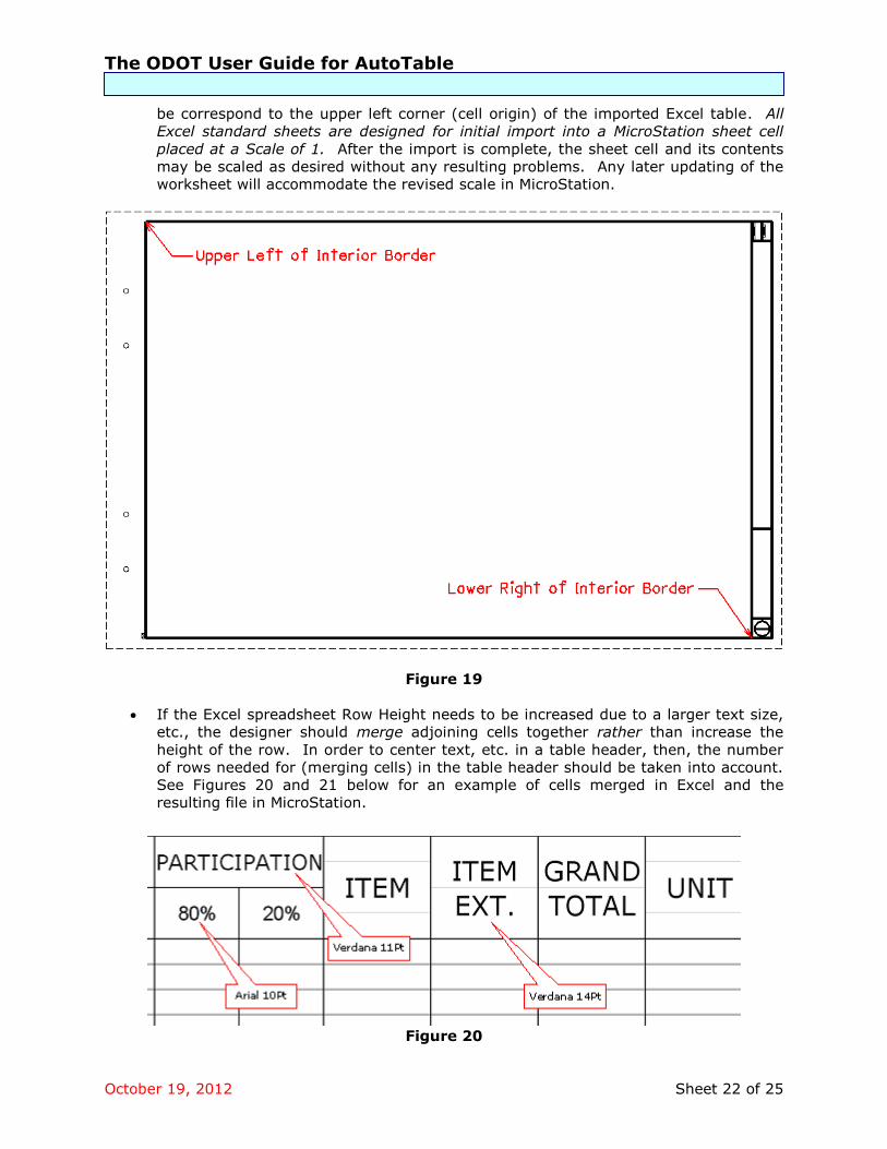
The ODOT User Guide for AutoTable
October 19, 2012 Sheet 22 of 25
be correspond to the upper left corner (cell origin) of the imported Excel table. All
Excel standard sheets are designed for initial import into a MicroStation sheet cell
placed at a Scale of 1. After the import is complete, the sheet cell and its contents
may be scaled as desired without any resulting problems. Any later updating of the
worksheet will accommodate the revised scale in MicroStation.
Figure 19
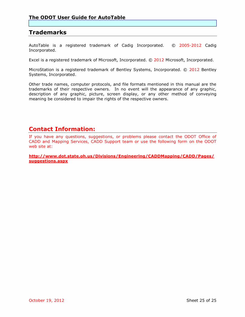
If the Excel spreadsheet Row Height needs to be increased due to a larger text size,
etc., the designer should merge adjoining cells together rather than increase the
height of the row. In order to center text, etc. in a table header, then, the number
of rows needed for (merging cells) in the table header should be taken into account.
See Figures 20 and 21 below for an example of cells merged in Excel and the
resulting file in MicroStation.
Figure 20

The ODOT User Guide for AutoTable
October 19, 2012 Sheet 23 of 25
Figure 20 shows four rows used in the Excel table header so that any text in the
column could be centered in the column allowing a larger text size to be used by
merging the cells. Notice the horizontal gray lines showing the merged cells in the
column headers.
The font types shown in Figure 20 are as per the ODOT standard Font Map
mentioned earlier in this document. The point sizes shown were selected to
duplicate the current General Summary (hard copy) sheet text sizes. These text
sizes are discussed in the Excel AutoTable Options | Scale section of this document.
Figure 21
Figure 21 shows the resulting import from the Excel file shown in Figure 20. Notice
the resulting sheet header showing the text, as specified in the Font Map, centered in
the columns.
Font 30 Font 70
Font 70

The ODOT User Guide for AutoTable
October 19, 2012 Sheet 24 of 25
Recommendations/Limitations
Screen resolution must be set at 96 dpi for AutoTable to work properly with the
ODOT standards. Other dpi settings will result in inaccurate import scaling.
Currently, AutoTable does not support stacked fractions for imported text. Fractions
displayed as text in the Excel worksheet will be placed in MicroStation as one line of
text.
Third party software or software Add-Ins, such as Microsoft Equation Editor, that
insert elements into an Excel worksheet may import incorrectly or not at all.
A picture and/or pie chart may be imported into the design file as a raster image via
the Create AutoTable command. The imported image can be seen in the Raster
Manager dialog box in MicroStation. There is, currently, no means by which such an
image placed from an Excel worksheet containing only that image can be updated
using the Edit AutoTable or the Update AutoTable commands from the MicroStation
AutoTable toolbar. A simple workaround for this situation is to place a small piece of
text (for example, a period) in the cell behind the image or to add something that
will become snappable in MicroStation to the picture in Excel (for example, a title).
Those working in Excel 2007 need to keep in mind that the default row height for a
new sheet is not 12.75 points as in earlier versions. Therefore, all cells from a user-
created Excel 2007 spreadsheet that will be imported into MicroStation must have
their row heights changed to 12.75 for the ODOT standard settings to work correctly.
Excel 2007 does not necessarily display rows in direct to proportion to their height.
For example, if you double the row height, what you actually see may be 2.1 times
larger. The floating border, however, is displayed correctly. Therefore, the location
of the last row of your chart relative to the floating border may be totally different
than how it will appear relative to the bottom of the sheet’s inner border once it is
imported into MicroStation. To ensure that your Excel 2007 chart fits within a
standard ODOT sheet cell’s drawing area, the cumulative row height should be no
more than 959.5 points.
Cadig recommends that, when a user prepares a worksheet in Excel using the
Format Cells option, he/she format only the cells needed for input within the Excel
worksheet to prevent possible placement of the entire worksheet.
The ODOT User Guide for AutoTable
October 19, 2012 Sheet 25 of 25
Trademarks
AutoTable is a registered trademark of Cadig Incorporated. © 2005-2012 Cadig
Incorporated.
Excel is a registered trademark of Microsoft, Incorporated. © 2012 Microsoft, Incorporated.
MicroStation is a registered trademark of Bentley Systems, Incorporated. © 2012 Bentley
Systems, Incorporated.
Other trade names, computer protocols, and file formats mentioned in this manual are the
trademarks of their respective owners. In no event will the appearance of any graphic,
description of any graphic, picture, screen display, or any other method of conveying
meaning be considered to impair the rights of the respective owners.
Contact Information:
If you have any questions, suggestions, or problems please contact the ODOT Office of
CADD and Mapping Services, CADD Support team or use the following form on the ODOT
web site at:
http://www.dot.state.oh.us/Divisions/Engineering/CADDMapping/CADD/Pages/
suggestions.aspx
Related Documents