Measuring Projectile Velocity with Vacuum Tubes AF Filter Design * Electronic Oil Prospecting Postwar Home Radio Sets * OWI New York Studios OCTOBER Caldwell -Clements, Inc. www.americanradiohistory.com

Welcome message from author
This document is posted to help you gain knowledge. Please leave a comment to let me know what you think about it! Share it to your friends and learn new things together.
Transcript
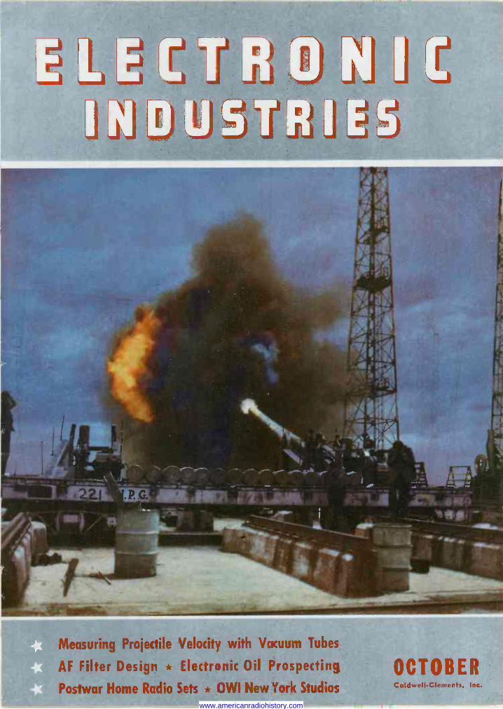
Measuring Projectile Velocity with Vacuum Tubes
AF Filter Design * Electronic Oil Prospecting
Postwar Home Radio Sets * OWI New York Studios
OCTOBER Caldwell -Clements, Inc.
www.americanradiohistory.com
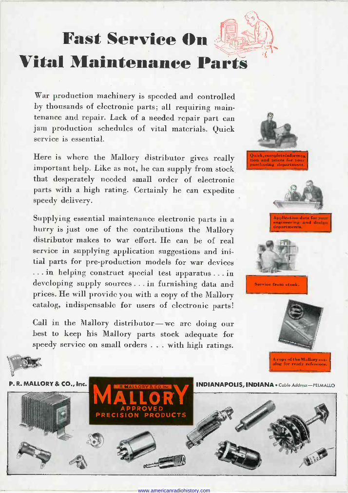
Fast Service On Vital Maintenance Parts
War production machinery is speeded and controlled by thousands of electronic parts; all requiring main- tenance and repair. Lack of a needed repair part can jam production schedules of vital materials. Quick service is essential.
Here is where the Mallory distributor gives really important help. Like as not, he can supply from stock that desperately needed small order of electronic parts with a high rating. Certainly he can expedite speedy delivery.
Supplying essential maintenance electronic parts in a hurry is just one of the contributions the Mallory distributor makes to war effort. He can be of real service in supplying application suggestions and ini- tial parts for pre -production models for war devices ... in helping construct special test apparatus ... in developing supply sources ... in furnishing data and prices. He will provide you with a copy of the Mallory catalog, indispensable for users of electronic parts!
Call in the Mallory distributor - we are doing our best to keep his Mallory parts stock adequate for speedy service on small orders ... with high ratings.
P. R. MALLORY & CO., Inc.
MALLORY APPROVED
PRECISION PRODUCTS
engiñlrpriiïgan eiaßn
5rY icg. fryni. e, 4..
Maliorÿ alog for ready reference.
INDIANAPOLIS, INDIANA Cable Address-PELMALLO
www.americanradiohistory.com
TYPE RATINGS
STANDARD CAPACITY TEST VOLTAGE GROUND TEST
SHUNT RESISTANCE
POWER FACTOR CONTAINER SIZE
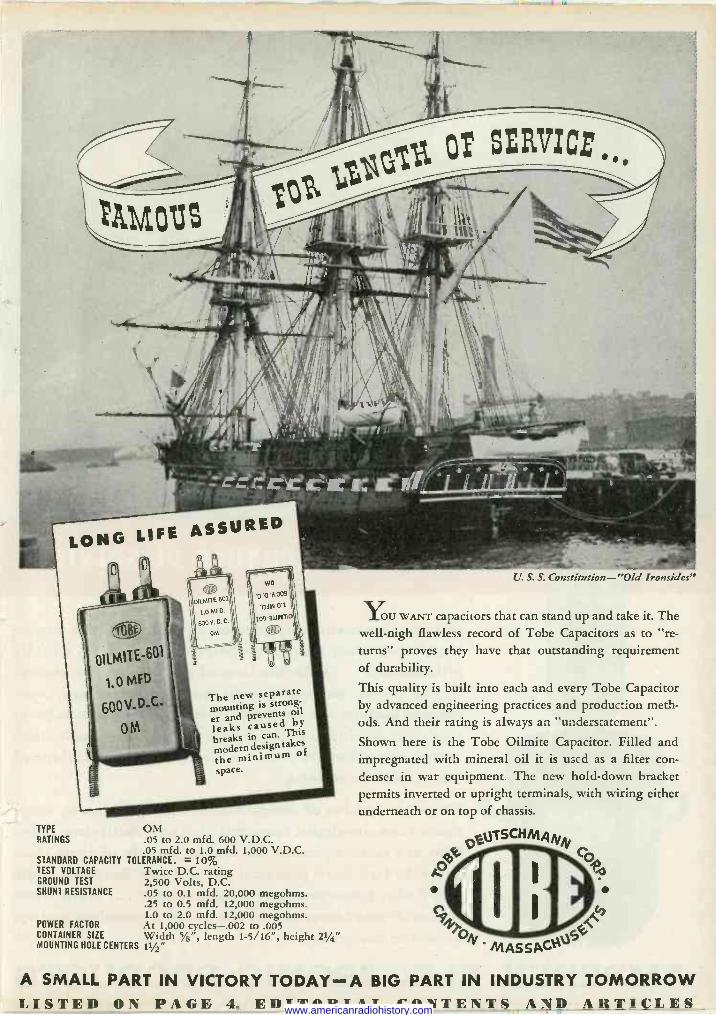
The new separate mounting is strong-
er and prevents ml
leaks caused by
breaks in can. This modern design takes
the minimum of
space.
OM .05 to 2.0 mfd. 600 V.D.C. .05 mfd. to 1.0 mfd. 1,000 V.D.C.
TOLERANCE. = 10% Twice D.C. rating 2,500 Volts, D.C. .05 to 0.1 mfd. 20,000 megohms. .25 to 0.5 mfd. 12,000 megohms. 1.0 to 2.0 mfd. 12,000 megohms. At 1,000 cycles-.002 to .005 Width 5/e", length 1-5/16", height 21/4"
MOUNTING HOLE CENTERS 11/2"
U. S. S. Constitution-"Old Ironsides"
YOU WANT capacitors that can stand up and take it. The well-nigh flawless record of Tobe Capacitors as to "re- turns" proves they have that outstanding requirement of durability.
This quality is built into each and every Tobe Capacitor by advanced engineering practices and production meth- ods. And their rating is always an "understatement".
Shown here is the Tobe Oilmite Capacitor. Filled and impregnated with mineral oil it is used as a filter con-
denser in war equipment. The new hold-down bracket permits inverted or upright terminals, with wiring either underneath or on top of chassis.
A SMALL PART IN VICTORY TODAY- A BIG PART IN INDUSTRY TOMORROW LISTED ON PAGE 4, EDITORIAL CONTENTS AND ARTICLES www.americanradiohistory.com
` zeh ` f..J.? -a ti ., . , -'- ,.;lS.3Fák 1Ya ìa .J... "t + ...L 3? _ ir±.r .i L/'í1¡.
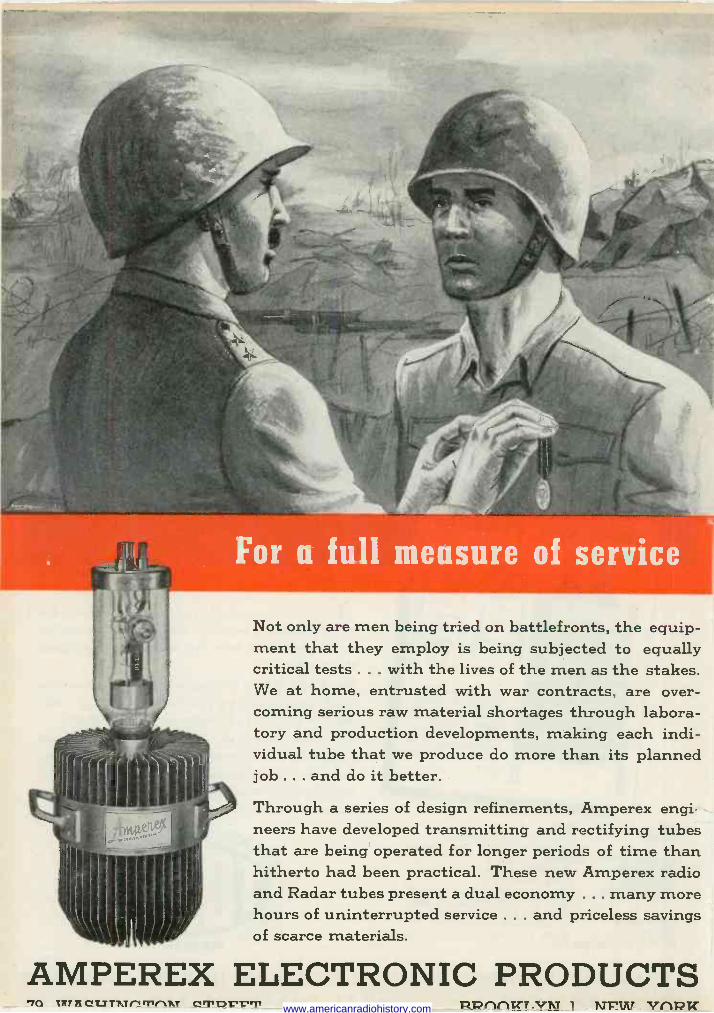
For a full measure of service
Not only are men being tried on battlefronts, the equip- ment that they employ is being subjected to equally critical tests ... with the lives of the men as the stakes. We at home, entrusted with war contracts, are over- coming serious raw material shortages through labora- tory and production developments, making each indi- vidual tube that we produce do more than its planned job ... and do it better.
Through a series of design refinements, Amperex engi neers have developed transmitting and rectifying tubes that are being operated for longer periods of time than hitherto had been practical. These new Amperex radio and Radar tubes present a dual economy ... many more hours of uninterrupted service ... and priceless savings of scarce materials.
AMPEREX ELECTRONIC PRODUCTS In Inn CL7TT.T/'i Tl1AT CTDL'L'T - R17rVlKT.VN 1 NFIII) V(1RK www.americanradiohistory.com
Adlake !'l,e Mercury Relays
STAMINA SI MPUyty
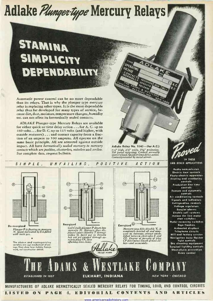
Automatic power control can be no more dependable than its relays. That is why the plunger type mercury relay is replacing other types. It is the most dependable relay thus far developed for many types of service, be- cause dirt, dust, moisture, temperature changes, humidity etc. can not affect its hermetically sealed contacts.
ADLAKE Plunger -type Mercury Relays are available for either quick or time delay action ... for A. C. up to 440 volts ... for D. C. up to 115 volts (and higher, with outside resistors) ... and contact capacity from a frac- tion of an ampere to 100 amperes. All operate on the same basic principle. All are armored against outside impact. All have hermetically sealed mercury to mercury contacts which are positive, chatterless, noiseless and arcless. For complete data, request bulletin.
bM1
Adlake Relay No. 1040-(for A.C.) 53íj' high,, 23Ç' wide, 2!.4" projection. For Panel mounting. Contact normally open or closed. Quick or time delay action. Contact protected by metal armor.
S I M P L E, UNFAILING, POSITIVE ACTION
De -energized Plunger P is floating in mercury M. Space indicated by S isfilled with inert gas.
The above and accompanying sketches are not mechanical draw- ings. They show how Adlake Relays work, not construction detail.
Energized Coil C pulls Plunger P down into mercury M. Mercury thus dis-
placed enters thimble T through orifice O. Inert gas in thimble has not yet escaped through ce. ramie plug CP, thus effecting time delay.
MARK
Energized Mercury now fi Is thimble T, is completely leveled off and mer- cury to mercury contact estab- lished betwe_m electrodes E and EE. Degree of porosity of plug CP determines length of time de- lay-and accurately.
IN THESE
AND OTHER APPLICATIONS
Radio transmission Electric time controls
Photo -electric apparatus Heating and ventilating
controls Production line time
controls Remote and automatic
controls Air conditioning controls
Signals and indicators Refrigeration controls
Voltage regulators Burglar alarms
Electric call systems Across the line motor
start switches Motor reversing switches
Sign flashers Animated displays Telephone circuits
Mill and factory service Navigation buoy flasher
light controls Dry cleaning equipment
Surgical lighting controls Electrolysis prevention
X-ray control
THE ituits &ESTLAKE COMPANY ESTABLISHED IN 1857 ELKHART, INDIANA NEW YORK CHICAGO
MANUFACTURERS OF ADLAKE HERMETICALLY SEALED MERCURY RELAYS FOR TIMING, LOAD, AND CONTROL CIRCUITS
LISTED ON PAGE 4. EDITORIAL CONTENTS AND ARTICLES www.americanradiohistory.com
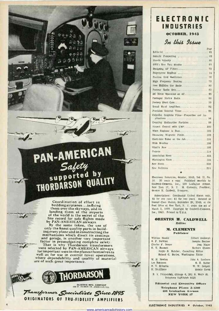
Coordination of effort in building airplanes ... in flying
them over the skyways, and in landing them at the airports of the world is the secret of the
fine record for safe flights made by PAN-AMERICAN airways.
By the same token, the use of only the finest quality parts in build- ing every plane and in constructing the
mechanisms which direct its comings and goings, is another very important
factor in promulgating complete safety. That is why Thordarson transformers
were selected by PAN-AMERICAN airways for important uses in the planes themselves as
well as for use in control tower operations, where dependability and quality of material
are of such great importance.
[ ItIORDARSON ELECTRIC MFG. COMPANY
605 W. HURON ST.,CHICACO.ILL.
.t 4.57.deet..se 4 W95
ORIGINATORS OF TRU-FIDELITY AMPLIFIERS
.," - cà/..*. ._
., . ef.
ELECTRONIC INDUSTRIES
OCTOBER, 1943
90t add 9444e Page
Editorial 61
Seismic Prospecting 62
Muzzle Velocity 66
OWI's New York Studios 68
Designing AF Filters 72
Polystyrene Replicas 74
Positive Grid Oscillators 76
High Frequency Heating 79
How Utilities Use Radio 80
Postwar Radio Sets 82
DC Motor Operation on AC 85
Packaged Marine Radio 88
Factory Short Cuts 90
Broad Band Amplifiers 92
Precision Interval Timer 95
Collofâal Graphite Films-Properties and Ap- plications 96
Counting Radioactive Particles 99
Airport Control with UHF 100
When Engineer is Boss 102
Measuring Magnetic Fields 103
Electronic Tubes on the Job 104
Wide Reading 106
What's New 108
Patents 114
Association News 124
Washington News 134
New Books 218
New Bulletins 222
Electronic Industries, October, 1943, Vol. II, No.
10. 35 cents a copy. Published monthly by
Caldwell -Clements, Inc., 480 Lexington Avenue,
New York 17, N. Y. M. Clements, President; Orestes H. Caldwell, Treasurer.
Subscriptions: Continental United States only, $3 for one year; $5 for two years. Entered as Second Class Matter, September 20, 1943, at the Post Office at New York, N. Y. under the act of March 3, 1879. Copyright by Caldwell -Clements, Inc., 1943. Printed in U.S.A.
ORESTES H. CALDWELL Editor
M. CLEMENTS Publisher
William Mantic S. P. McMinn
Charles F. Dreyer E. T. Bennett
Gilbert Sonbergh Josepha Zentner
Jean Mayer Barbara Chosen
Ralph R. Batcher, Consulting Editor Roland C. Davies, Washington Editor
M. H. Newton John A. Samborn Lee Robinson O. H. Sutter B. V. Spinette W. W. Swigert N. McAllister Estelle Coven
R. Y. Fitzpatrick, Chicago 6, 201 N. Wells St. Telephone RANdolph 9225
Editorial and Executive Offices Telephone PLaaa 3-1340 480 Lexington Avenue
NEW YORK 17
4 ELECTRONIC INDUSTRIES October, 1943
www.americanradiohistory.com
No. 6 OF A SERIES EXPLAINING THE USES OF ELEC'T'RONIC TUBES IN INDUSTRY
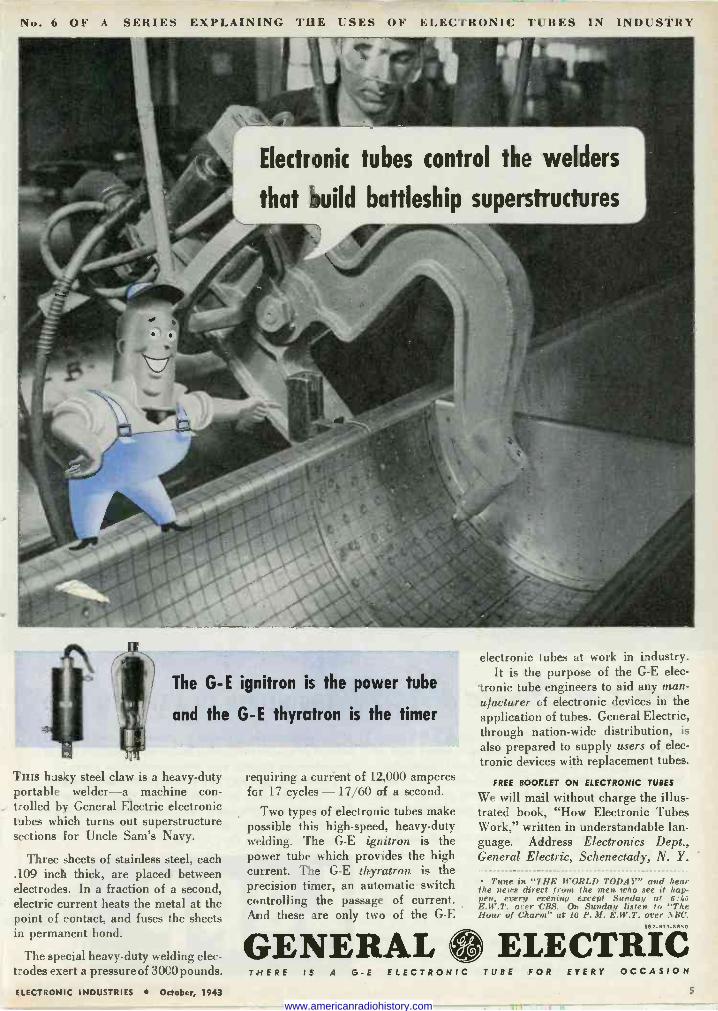
Electronic tubes control the welders
that build battleship superstructures
The G- E ignitron is the power tube
and the G -E thyratron is the timer
Tins husky steel claw is a heavy-duty portable welder-a machine con- trolled by General Electric electronic tubes which turns out superstructure sections for Uncle Sam's Navy.
Three sheets of stainless steel, each .109 inch thick, are placed between electrodes. In a fraction of a second, electric current heats the metal at the point of contact, and fuses the sheets in permanent bond.
The special heavy-duty welding elec- trodes exert a pressure of 3000 pounds.
ELECTRONIC INDUSTRIES October, 1943
requiring a current of 12,000 amperes for 17 cycles -17/60 of a second.
Two types of electronic tubes make possible this high-speed, heavy-duty welding. The G -E ignitron is the power tube which provides the high current. The G -E thyratron is the precision timer, an automatic switch controlling the passage of current. And these .Ire only two of the G -E
GENERAL
electronic tubes at work in industry. It is the purpose of the G -E elec-
tronic tube engineers to aid any man- ufacturer of electronic devices in the application of tubes. General Electric, through nation-wide distribution, is
also prepared to supply users of elec- tronic devices with replacement tubes.
FREE BOOKLET ON ELECTRONIC TUBES
We will mail without charge the illus- trated book, "How Electronic Tubes Work," written in understandable lan- guage. Address Electronics Dept., General Electric, Schenectady, N. Y.
Tune in "THE WORLD TODAY" and hear the news direct from the men, who see it hap- pen, every evening except Sunday at 0:1,5 E.W.T. over 'CBS. On Sunday listen. t., "The Hour of Charm" at 10 P. M. E.W.T. orrr NBC.
162 -BI 3-SS50
ELECTRIC THERE IS A G -E ELECTRONIC TUBE FOR EVERY OCCASION
5
www.americanradiohistory.com
Z.iÉ[4elde .. ENGINEERED TO A SPECIFIC NEED
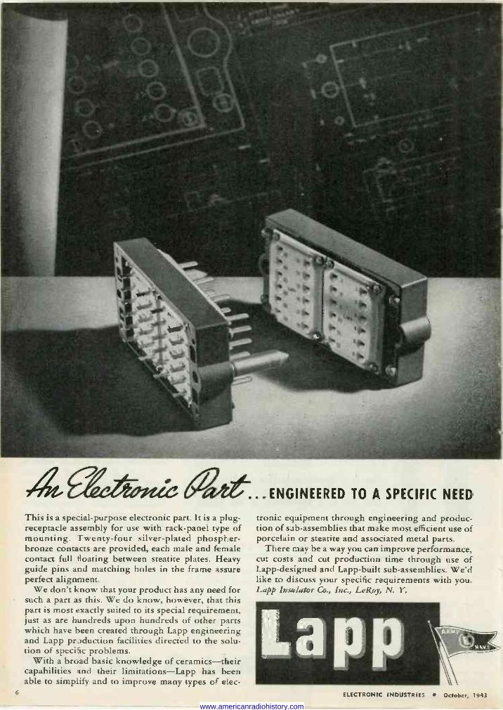
This is a special-purpose electronic part. It is a plug - 'receptacle assembly for use with rack -panel type of mounting. Twenty-four silver-plated phospher- bronze contacts are provided, each male and female contact full floating between steatite plates. Heavy guide pins and matching holes in the frame assure perfect alignment.
We don't know that your product has any need for such a part as this. We do know, however, that this part is most exactly suited to its special requirement, just as are hundreds upon hundreds of other parts which have been created through Lapp engineering and Lapp production facilities directed to the solu- tion of specific problems.
With a broad basic knowledge of ceramics-their capabilities and their limitations-Lapp has been able to simplify and to improve many types of elec-
tronic equipment through engineering and produc- tion of sub -assemblies that make most efficient use of porcelain or steatite and associated metal parts.
There may be a way you can improve performance, cut costs and cut production time through use of Lapp -designed and Lapp -built sub -assemblies. We'd like to discuss your specific requirements with you. Lapp Insulator Co., Inc., LeRoy, N. Y.
6 ELECTRONIC INDUSTRIES October, 1943
www.americanradiohistory.com
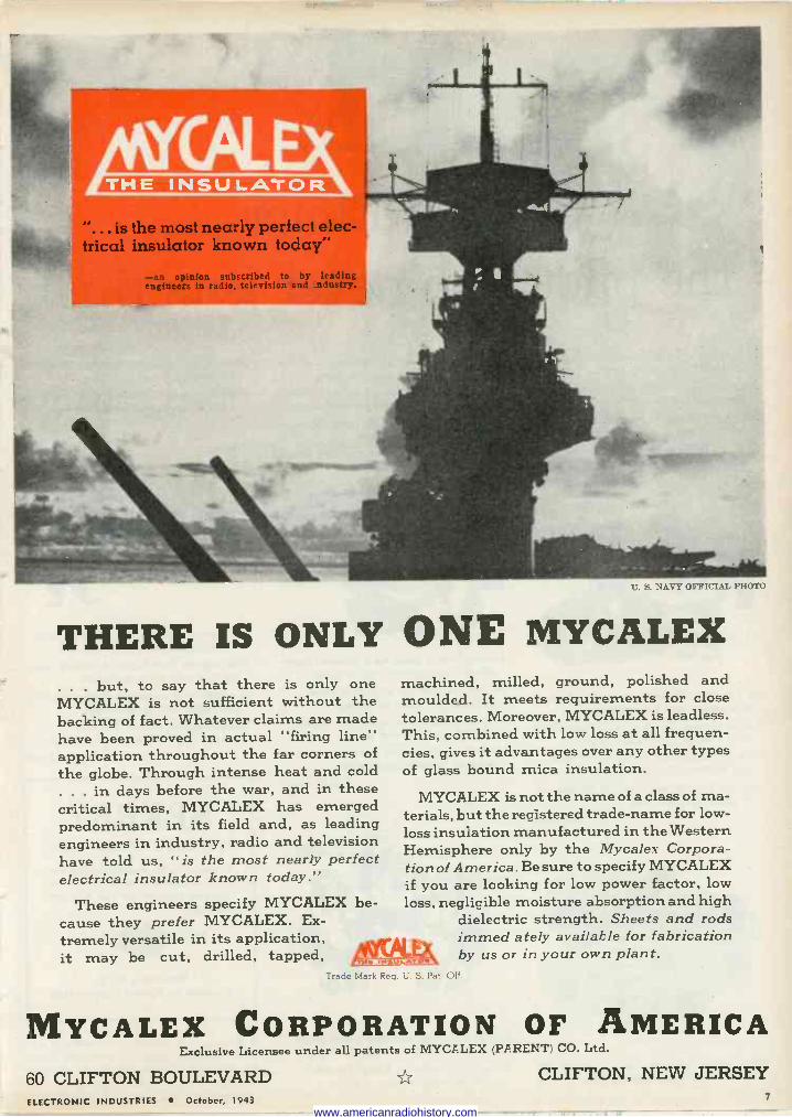
e erfect elec- trical insulator known today"
-an opinion subscribed to by leading engineers in radio, television and =ndustry.
t. S. NAVY OFFICIAL PHOTO
THERE IS ONLY ONE MYCALEX . . . but, to say that there is only one MYCALEX is not sufficient without the backing of fact. Whatever claims are made have been proved in actual "firing line" application throughout the far corners of the globe. Through intense heat and cold . . . in days before the war, and in these critical times, MYCALEX has emerged predominant in its field and, as leading engineers in industry, radio and television have told us, "is the most nearly perfect electrical insulator known today."
These engineers specify MYCALEX be- cause they prefer MYCALEX. Ex- tremely versatile in its application, immed ately available for fabrication it may be cut, drilled, tapped, by us or in your own plant.
machined, milled, ground, polished and moulded. It meets requirements for close tolerances. Moreover, MYCALEX is leadless. This, combined with low loss at all frequen- cies, gives it advantages over any other types of glass bound mica insulation.
MYCALEX is not the name of a class of ma- terials, but the registered trade -name for low - loss insulation manufactured in the Western Hemisphere only by the Mycalex Corpora- tion of America. Be sure to specify MYCALEX if you are looking for low power factor, low loss, negligible moisture absorption and high
dielectric strength. Sheets and rods l: . G.;1S:ZT57 .i
Trade Mark Req. U. S. Pat Off
MYCALEX CORPORATION OF AMERICA Exclusive Licensee under all patents of MYCALEX (PARENT) CO. Ltd.
60 CLIFTON BOULEVARD CLIFTON, NEW JERSEY ELECTRONIC INDUSTRIES October, 1943 7
www.americanradiohistory.com
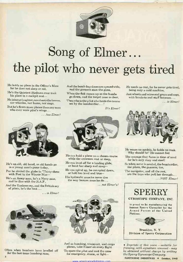
Song of Elmer... the pilot who never gets tired
He holds no place in the Officer's Mess for he does not sleep or eat,
He's the Quietest Birdman ever took his place in a cockpit seat-
He joins no laughter, nor shoots the breeze, nor whistles, nor hums, nor sings,
But he's flown more planes than any man who ever wore pilot's wings...
. has Elmer!
He's an old, old hand, as old hands go in a young man's game today,
For he circled the globe in 'Thirty-three with Post in the Winnie Mae-
He's an Army man, he's a Navy man, and he flies with the R.A.F.,
And the Yankees say, and the British say of pilots, he's the best...
. is Elmer!
Often when bombers have levelled off for the last tense bombing runs,
And the bomb -bay doors are opened wide, and the gunners man the guns,
When the flak comes up as the bombs go down, and the target zone is clear,
Then who is the pilot who holds the course set by the bombardier ... ?
It's Elmer!
He can hold a plane on a chosen course while the crewmen rest or sleep,
He can level off for a landing glide, or bank her sharp and steep-
He can spiral up, he can spiral down, or hold her level and true-
His hydraulic muscles never tire the way human muscles do ...
...not Elmer's!
And so bombing, transport, and cargo planes, take Elmer on every flight
To spare the pilot and rest the crew for emergency, storm, or fight-
He needs no rest, for he never gets tired, being only a cold machine,
Just wheels and wires and gears and cogs, with brackets and stuff between...
...is Elmer!
He wears no medals, he holds no rank. Why should he? He cannot feel
The courage that flares in time of need for he's only ahoy and steel!
So when nerve is needed, the bombardier, the pilots, the gunners, too,
The navigator, and all the rest, are the boys who pull her through...
.. NOT Elmer!
SPERRY GYROSCOPE COMPANY, INC.
is proud to be manufacturing the famous Sperry Gyropilot for the Armed Forces of the United Nations.
Brooklyn, N. Y. Division of Sperry Corporation
Reprints of this poem - suitable for framing, with signature removed-may be obtained without charge by writing the Sperry Gyroscope Company.
ELECTRONIC INDUSTRIES October, 1943 8
www.americanradiohistory.com
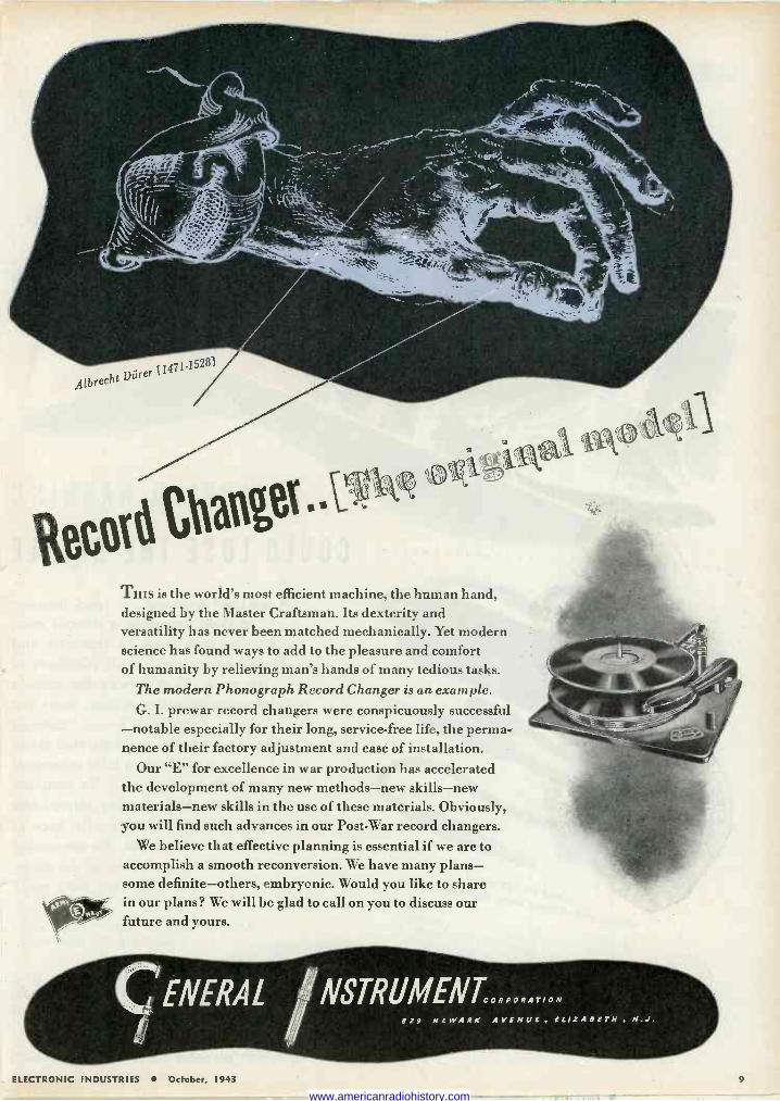
Albrecht Dürer [1471.15281
to" Chane ..\_
THIS is the world's most efficient machine, the human hand, designed by the Master Craftsman. Its dexterity and versatility has never been matched mechanically. Yet modern science has found ways to add to the pleasure and comfort of humanity by relieving man's hands of many tedious tasks.
The modern Phonograph Record Changer is an example. G. I. prewar record changers were conspicuously successful
-notable especially for their long, service -free life, the perma- nence of their factory adjustment and ease of installation.
Our "E" for excellence in war production has accelerated the development of many new methods-new skills-new materials-new skills in the use of these materials. Obviously, you will find such advances in our Post -War record changers.
We believe that effective planning is essential if we are to accomplish a smooth reconversion. We have many plans- some definite-others, embryonic. Would you like to share in our plans? We will be glad to call on you to discuss our future and yours.
ENERAL NSTRUMENTCORPORAT,ON 829 NEWARK AVENUE , ELIZABETH
ef\
ELECTRONIC INDUSTRIES October, 1943 9
www.americanradiohistory.com
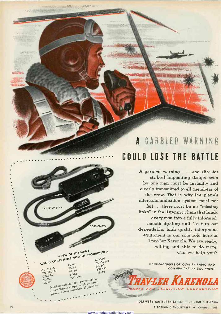
A GARBLED WARNING
... COULD LOSE THE BATTLE
A FEW OfÑÓWMN pROQutt10N:
SIGNAL CORPS
ITEMS
47 gC 347.0
PL- 86
CD -31.8-A. PL -54 PE -86
CD -301 -/k. PL -SS Ig.47
CD -g74 PL -68 A, Plug
75-6 ranYtYPeofu.S { 1g.48 Navy
Inter- IngoiriSig°nQ311Co Corps
or ment.
Array Communication
EguiP
. e
Com Phon
. '
A garbled warning . . . and disaster strikes! Impending danger seen
by one man must be instantly and clearly transmitted to all members of
the crew. That is why the plane's intercommunication system must not
fail ... there must be no "missing links" in the listening chain that binds
every man into a fully informed, smooth -fighting unit. To turn out
dependable, high quality interphone equipment is our sole role here at
Trav-Ler Karenola. We are ready, willing and able to do more.
Can we help you?
MANUFACTURERS OF QUALITY RADIO AND COMMUNICATION EQUIPMENT
'AVM KARIN//ZA DIO A '-TELEVISION CORPORATION
1032 WEST VAN BUREN STREET CHICAGO 7, ILLINOIS
ELECTRONIC INDUSTRIES October, 1943 lo
www.americanradiohistory.com
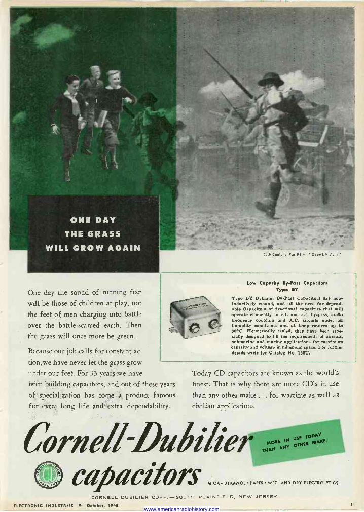
One day the sound of running feet
will be those of children at play, not
the feet of men charging into battle
over the battle -scarred earth. Then
the grass will once more be green.
Because our job calls for constant ac-
tion,we have never let the grass grow
under our feet. For 33 years we have
been building capacitors, and out of these years
of specialization has come a product famous
for extra long life and` extra dependability.
:0th Century -FA( Film "Desert Victory"
Low Capacity By -Pass Capacitors Type DY
Type DY Dykanol By -Pass Capacitors are non - inductively wound, and fill the need for depend- able Capacitors of fractional capacities that will operate efficiently in r.f. and a.f. by-pass, audio frequency coupling and A.C. circuits ender all humidity conditions and at temperatures up to 80°C. Hermetically sealed, they have been espe- cially designed to fill the requirements of aircraft, submarine and marine applications for maximum capacity and voltage in minimum space. For further details write for Catalog No. 160T.
Today CD capacitors are known as the world's
finest. That is why there are more CD's in use
than any other make . .. for wartime as well as
civilian applications.
Corneil-Duéilier capacitors
1N USE 10010
:µA14 ANY OCKER MOM.
MICA DYKANOL PAPER WET AND DRY ELECTROLYTICS
CORNELL-DUBILIER CORP.-SOUTH PLAINFIELD, NEW JERSEY
ELECTRONIC INDUSTRIES October, 1943 11
www.americanradiohistory.com
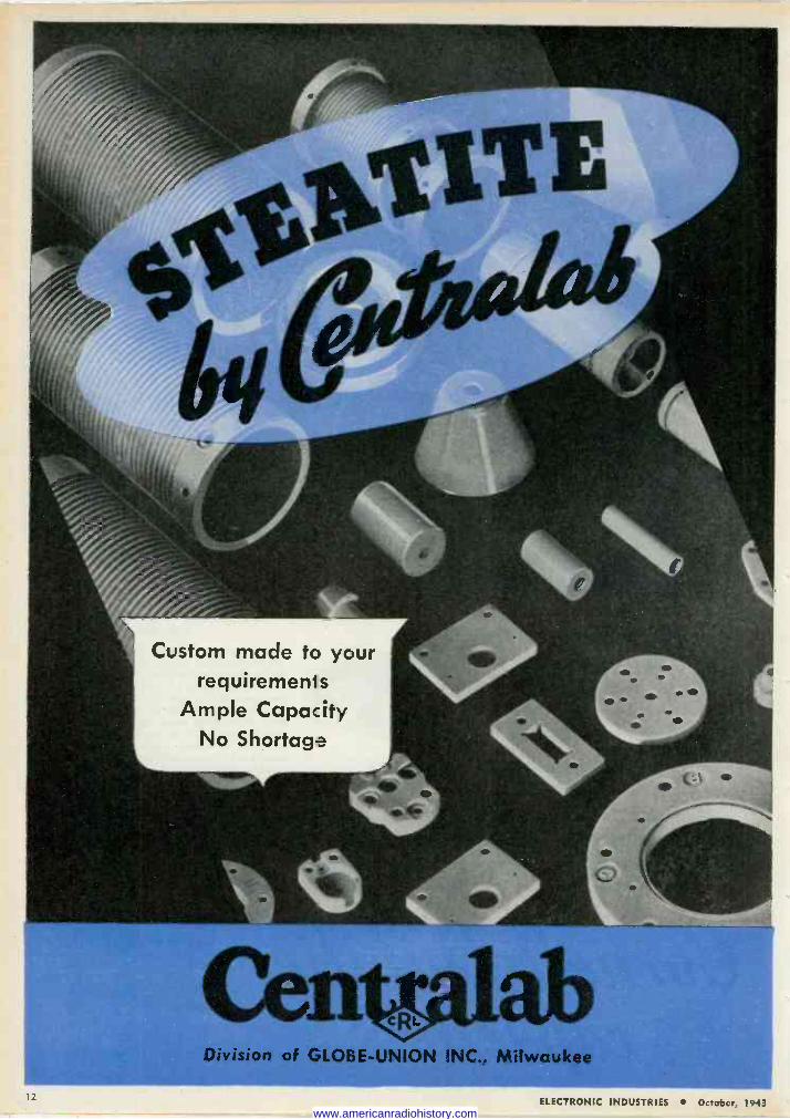
Custom made to your requirements
Ample Capacity No Shortage
Division of GLOBE-llN1C1N INC.. Milwaukee
12
www.americanradiohistory.com
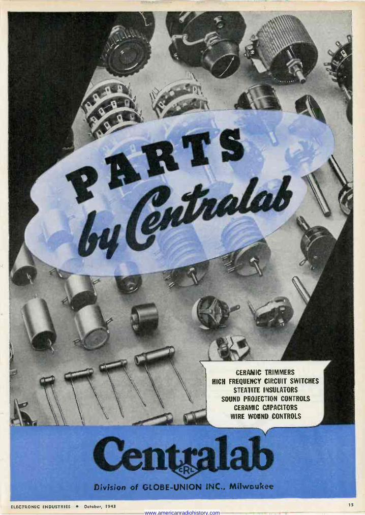
CERAMIC TRIMMERS
HIGH FREQUENCY CIRCUIT SWITCHES
STEA1 ITE I 4SULATORS
SOUND PROJECTION CONTROLS
CERAMIC CAPACITORS
WIRE WOUND CONTROLS
Division of GLOBE -UNION INC., NUIwcuIcee
ELECTRONIC INDUSTRIES www.americanradiohistory.com
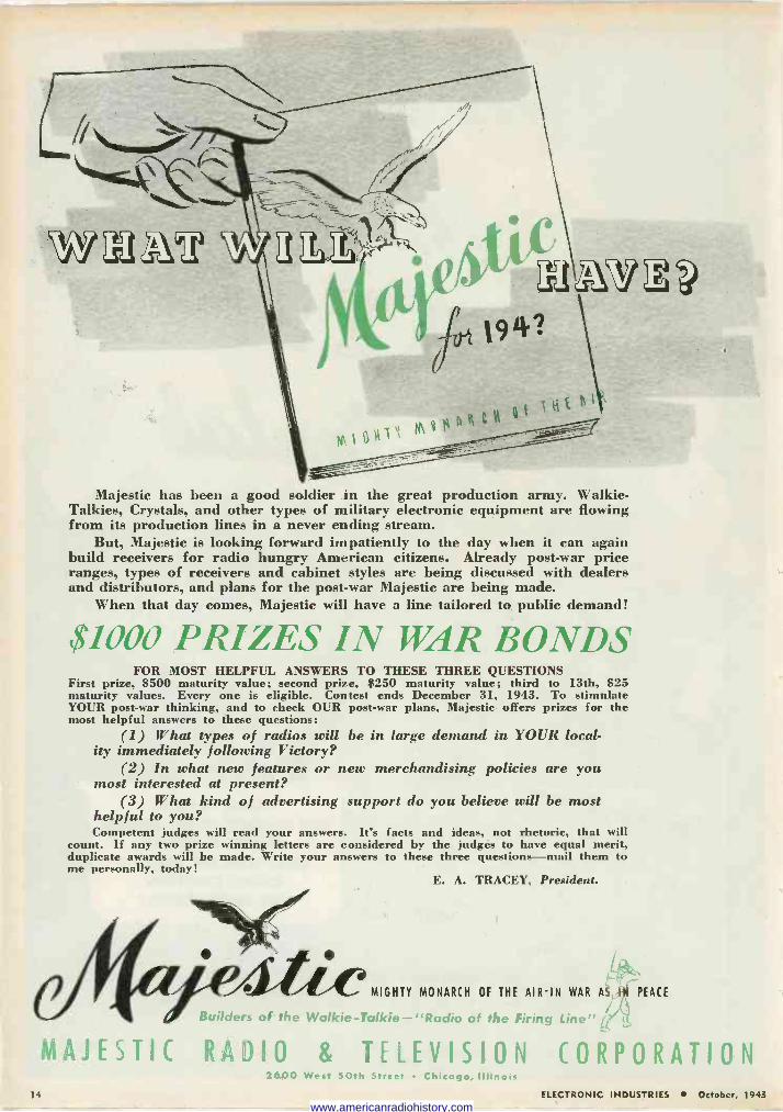
Majestic has been a good soldier in the great production army. Walkie- Talkies, Crystals, and other types of military electronic equipment are flowing from its production lines in a never ending stream.
But, Majestic is looking forward impatiently to the day when it can again build receivers for radio hungry American citizens. Already post-war price ranges, types of receivers and cabinet styles are being discussed with dealers and distributors, and plans for the post-war Majestic are being made.
When that day comes, Majestic will have a line tailored to public demand!
$1000 PRIZES IN WAR BONDS FOR MOST HELPFUL ANSWERS TO THESE THREE QUESTIONS
First prize, $500 maturity value; second prize, $250 maturity value; third to 13th, $25 maturity values. Every one is eligible. Contest ends December 31, 1943. To stimulate YOUR post-war thinking, and to check OUR post-war plans, Majestic offers prizes for the most helpful answers to these questions:
(1) What types of radios will be in large demand in YOUR local- ity immediately following Victory?
(2) In what new features or new merchandising policies are you most interested at present?
(3) What kind of advertising support do you believe will be most helpful to you? Competent judges will read your answers. It's facts and ideas, not rhetoric, that will
count. If any two prize winning letters are considered by the judges to have equal merit, duplicate awards will be made. Write your answers to these three questions-mail them to me personally, today!
E. A. TRACEY, President.
MIGHTY MONARCH OF THE AIR -IN WAR AS IN PEACE
Builders of the Walkie-Talkie-"Radio of the Firing Line"ía
MAJESTIC RADIO & TELEVISION CORPORATION 2600 West 50th Street Chicago, Illinois
14 ELECTRONIC INDUSTRIES October, 1943
www.americanradiohistory.com
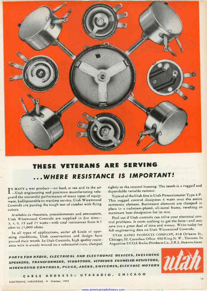
THESE VETERANS ARE SERVING
...WHERE RESISTANCE IS IMPORTANT!
N MANY a war product-on land, at sea and in the air I-Utah engineering and precision manufacturing safe-
guard the successful performance of many types of equip-
ment. Indispensable to wartime service, Utah Wirewound Controls are passing the tough test of combat with flying
colors. Available in rheostats, potentiometers and attenuators,
Utah Wirewound Controls are supplied in five sizes - 3, 4, 9, 15 and 25 watts-with total resistances from 0.5
ohm to 25,000 ohms.
In all types of applications, under all kinds of oper-
ating conditions, Utah construction and design have
proved their worth. In Utah Controls, high quality resist-
ance wire is evenly wound on a substantial core, clamped
tightly to the control housing. The result is a rugged and
dependable variable resistor. Typical of the Utah line is Utah Potentiometer Type 4-P.
This rugged control dissipates 4 watts over the entire resistance element. Resistance elements are clamped in
place in a cadmium -plated, all -metal frame, resulting in
maximum heat dissipation for its size.
Find out if Utah controls can solve your electrical con-
trol problems. It costs nothing to get the facts-and may
save you a great deal of time and money. Write today for
full engineering data on Utah Wirewound Controls.
UTAH RADIO PRODUCTS COMPANY, 818 Orleans St.,
Chicago, Ill. Canadian Office: 850 King St. W., Toronto. In
Argentine: UCOA Radio Products Co., S.R.L. Buenos Aires.
PARTS FOR RADIO, ELECTRICAL AND ELECTRONIC DEVICES, INCLUDING
SPEAKERS, TRANSFORMERS, VIBRATORS, VITREOUS ENAMELED RESISTORS,
WIREWOUND CONTROLS, PLUGS, JACKS, SWITCHES, ELECTRIC MOTORS
CABLE A D D R E S S: U T A R A D 1 O, CHICAGO ELECTRONIC INDUSTRIES October, 1943
15
www.americanradiohistory.com
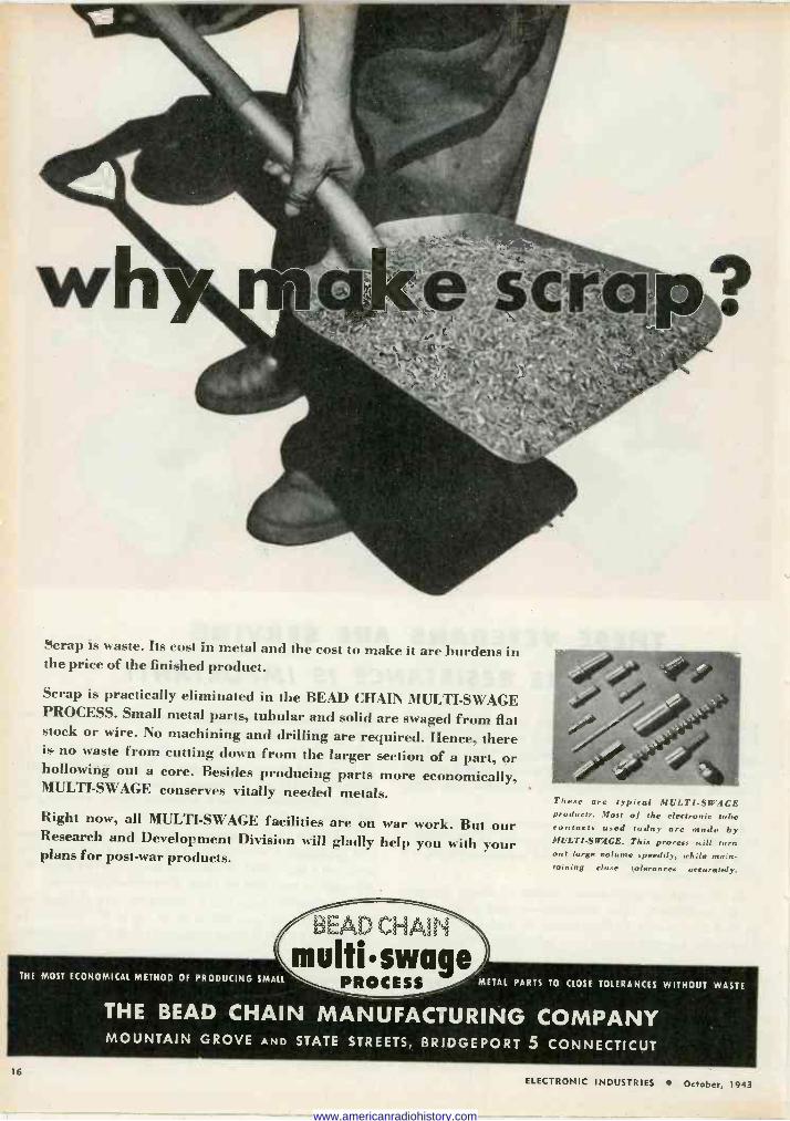
Scrap is waste. Its cost in metal and the cost to make it are burdens in the price of the finished product.
Scrap is practically eliminated in the BEAD CHAIN MULTI -SWAGE PROCESS. Small metal parts, tubular and solid are swaged from fiat stock or wire. No machining and drilling are required. Hence, there is no waste from cutting down from the larger section of a part, or hollowing out a core. Besides producing parts more economically, MULTI -SWAGE conserves vitally needed metals.
Right now, all MULTI -SWAGE facilities are on war work. But our Research and Development Division will gladly help you with your plans for post-war products.
THE MOST ECONOMICAL METHOD OF PRODUCING SMALL
BEAD CHAIN
multiswage PROCESS
These are typical MULTISW.4GE products, Most of the electronic tube contacts used today are made by MULTISW,1GE. This process still turn out large volume speedily, while ma:n- taining close tolerances accurately.
METAL PARTS TO CLOSE TOLERANCES WITHOUT WASTE
THE BEAD CHAIN MANUFACTURING COMPANY MOUNTAIN GROVE AND STATE STREETS, BRIDGEPORT 5 CONNECTICUT
16 ELECTRONIC INDUSTRIES October, 1943
www.americanradiohistory.com
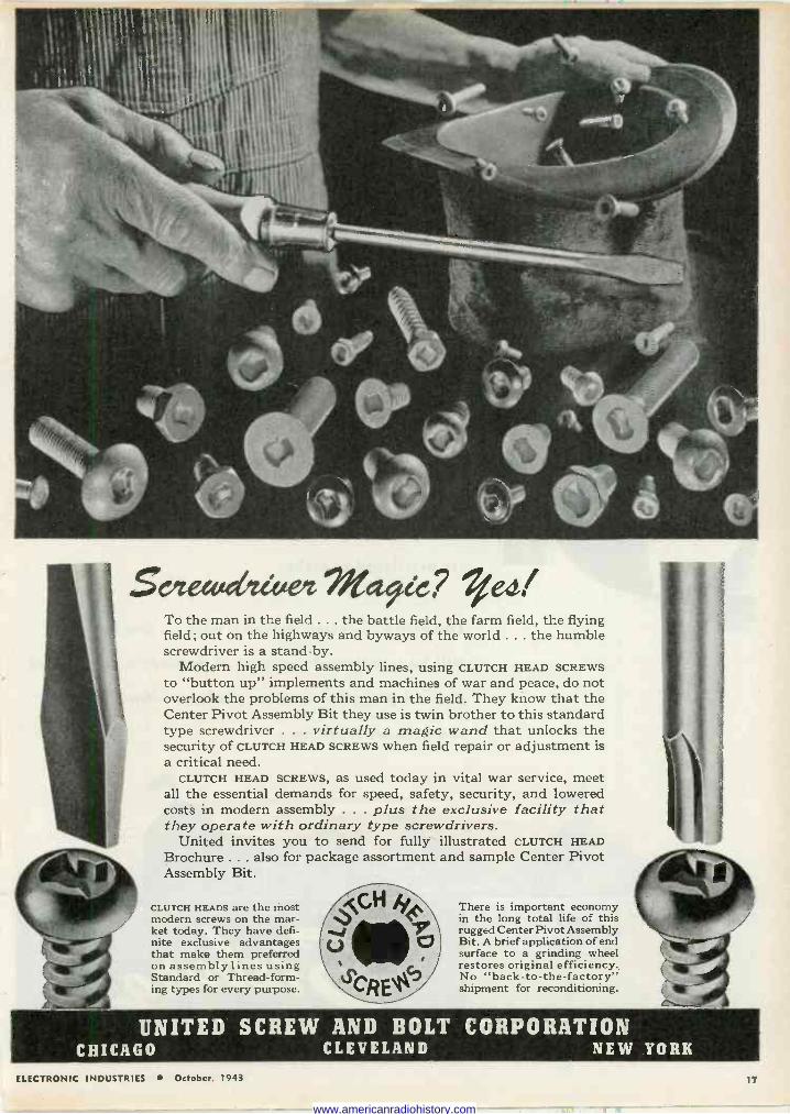
To the man in the field ... the battle field, the farm field, the flying field; out on the highways and byways of the world ... the humble screwdriver is a stand-by.
Modern high speed assembly lines, using CLUTCH HEAD SCREWS to "button up" implements and machines of war and peace, do not overlook the problems of this man in the field. They know that the Center Pivot Assembly Bit they use is twin brother to this standard type screwdriver . . . virtually a magic wand that unlocks the security of CLUTCH HEAD SCREWS when field repair or adjustment is a critical need. CLUTCH HEAD
all the essential costs in modern
SCREWS, as used today in vital war service, meet demands for speed, safety, security, and lowered assembly . . . plus the exclusive facility that
they operate with ordinary type screwdrivers. United invites you to send for fully illustrated CLUTCH HEAD
Brochure ... also for package assortment and sample Center Pivot Assembly Bit.
CLUTCH HEADS are the most modern screws on the mar- ket today. They have defi- nite exclusive advantages that make them preferred on assembly lines using Standard or Thread -form- ing types for every purpose.
`
There is important economy in the long total life off this rugged Center Pivot Assembly Bit. A brief application of end surface to a grinding wheel restores original efficiency. No "back -to -the -factory" shipment for reconditioning.
UNITED SCREW AND BOLT CORPORATION CHICAGO CLEVELAND NEW YORK
ELECTRONIC INDUSTRIES October. 1943 17
www.americanradiohistory.com
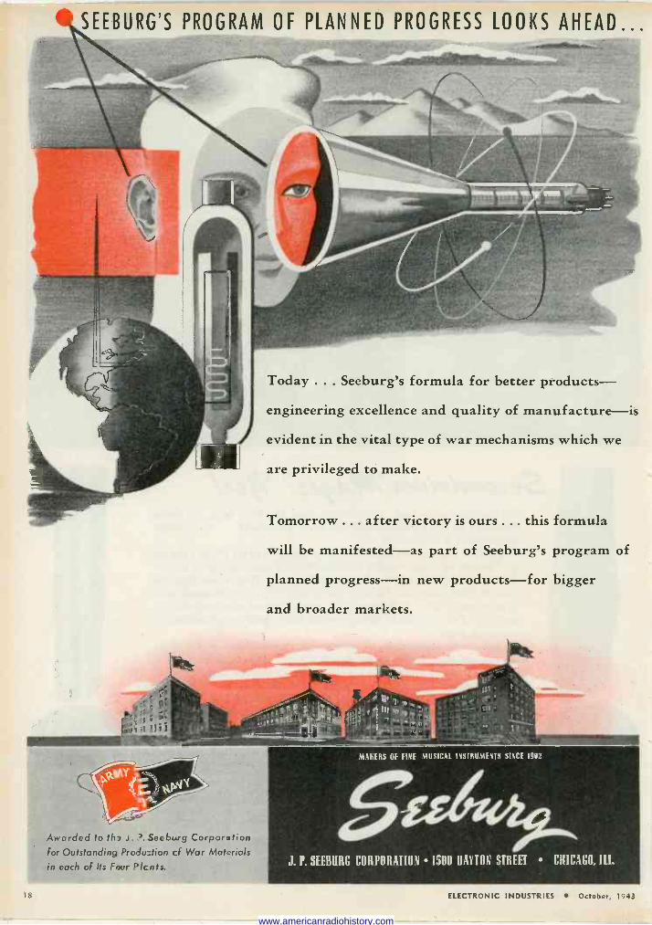
SEEBURG'S PROGRAM OF PLANNED PROGRESS LOOKS AHEAD...
Today ... Seeburg's formula for better products-
engineering excellence and quality of manufacture-is
evident in the vital type of war mechanisms which we
are privileged to make.
Tomorrow ... after victory is ours ... this formula
will be manifested-as part of Seeburg's program of
planned progress-in new products-for bigger
and broader markets.
Awarded to th J. . Seeburg Corporation for Outstanding Produ:tion cf War Materials
in each of Its Four Plc nts.
MAKERS OF FINE MUSICAL INSTRUMENTS SINCE 1902
5u4 ue. J. P. SEEBORG CORPORATION 1500 DAYTON STREET CHICAGO, Ill.
1S ELECTRONIC INDUSTRIES October, 1943
www.americanradiohistory.com
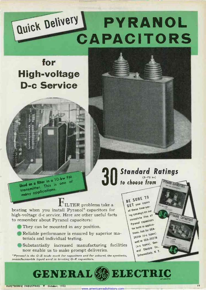
Quick DeliNe PYRANOL CAPACITORS
for High -voltage D -c Service
_ :,,,M,- _..'.__ -.._--10 -kv+ F M
Used OS o Alter in a is one
Of
transmitter. ihis
many applications -
30 FILTER problems take a
beating when you install Pyranol* capacitors for high -voltage d -c service. Here are other useful facts to remember about Pyranol capacitors:
They can be mounted in any position. Reliable performance is ensured by superior ma- terials and individual testing. Substantially increased manufacturing now enable us to make prompt deliveries.
*Pyranol is the G -E trade mark for capacitors and for askarel, the synthetic, noninflammable liquid used in treating G -E capacitors.
Standard Ratings (5-75 kv)
to choose from
facilities
BE SliRE ü GEI Ypqr coP18s
of these time -sm.
ing catalogs" pU¡f
complete "" PYrapOl capacitors
for bt,llt-ln aPPlica-
ilons. Ps fo[ GEA-
Z621A (d"C "Pes) andior
G.ZOGe g (a C
Wes)*
eral EleCtrlc CO"
SchenectadY, t4-
GENERAL ELECTRIC ELECTRONIC INDUSTRIES October l';13 14
www.americanradiohistory.com

/E HORIZONS ARS
www.americanradiohistory.com
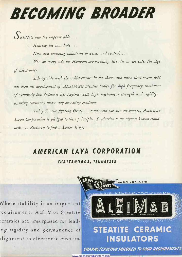
BECOMING BROADER
SEEING into the impenetrable .. .
Hearing the inaudible . .
New and amazing industrial processes and controls .. .
Yes, on every side the Horizons are becoming Broader as we enter the Age
of Electronics.
Side by side with the achievements in the short- and ultra short-wave field
has been the development of ALSIMAG Steatite bodies for high frequency insulators
of extremely low dielectric loss together with high mechanical strength and rigidity --
assuring constancy under any operating condition.
Today for ow- fighting forces ... tomorrow for our customers, American
Lava Corporation is pledged to these principles: Production tó the highest known stand-
ards ... Research to find a Better Way.
AMERICAN LAVA CORPORATION
CHATTANOOGA, TENNESSEE
Where stability is an important equirement; ALSIMAG Steatite :eramics are unsurpassed for lend-
ng rigidity and permanence of
alignment to electronic circuits.
AWARDED JULY 27, 1942
*XXX v
--_ _ =r=1-.-ë_ _ _-.i.- i... =-=
STEATITE CERAMIC INSULATORS
CHARACTERISTICS TAILORED TO YOUR REQUIREMENTS
www.americanradiohistory.com
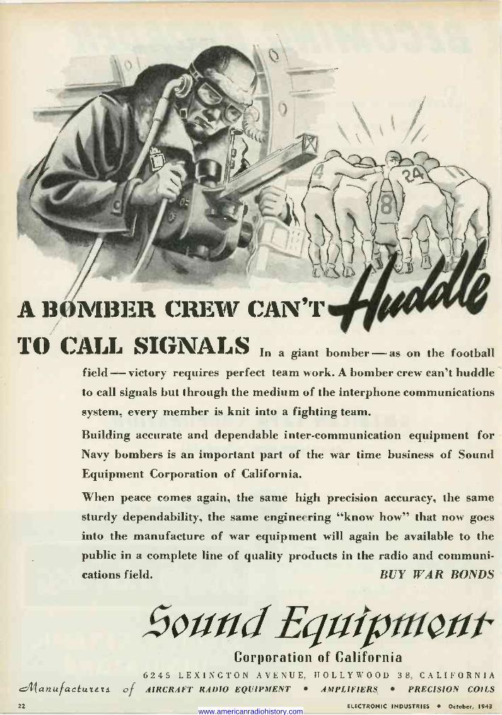
A 13 ( 1413E11 CREW CAN'T TO CALL SIGNALS In a giant bomber ason the football
field -victory requires perfect team work. A bomber crew can't huddle to call signals but through the medium of the interphone communications
system, every member is knit into a fighting team.
Building accurate and dependable inter -communication equipment for Navy bombers is an important part of the war time business of Sound Equipment Corporation of California.
When peace comes again, the same high precision accuracy, the same
sturdy dependability, the same engineering "know how" that now goes
into the manufacture of war equipment will again be available to the public in a complete line of quality products in the radio and communi-
cations field. BUY WAR BONDS
f3o#udEq#xptiiøíit Corporation of California
6245 LEXINGTON AVENUE, HOLLYWOOD 38, CALIFORNIA .it1anu factu¢E2s of AIRCRAFT RADIO EQUIPMENT AMPLIFIERS PRECISION COILS
22 ELECTRONIC INDUSTRIES October, 1943 www.americanradiohistory.com
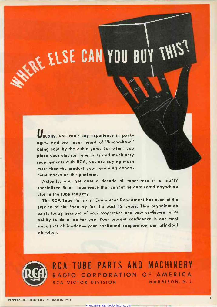
Usually, you can't buy experience in pack-
ages. And we never heard of "know-how" being sold by the cubic yard. But when you
place your electron tube parts and machinery
requirements with RCA, you are buying much
more than the product your receiving depart-
ment stacks on the platform. Actually, you get cver a decade of experience in a highly
specialized field-experience that cannot be duplicated anywhere
else in the tube industry. The RCA Tube Parts and Equipment Department has been at the
service of the industry for the past 12 years. This organization
exists today because of your cooperation and your confidence in its
ability to do a job for you. Your present confidence is our most
important obligation-your continued cooperation our principal
objective.
RCA TUBE PARTS AND MACHINERY RADIO CORPORATION OF AMERICA RCA VICTOR DIVISION HARRISON, N. J.
ELECTRONIC INDUSTRIES October, 1943
www.americanradiohistory.com
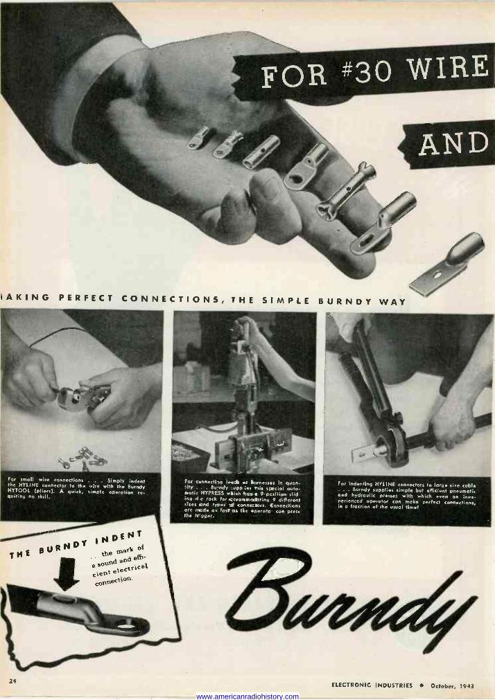
RAKING PERFECT CONNECTIONS, THE SIMPLE BURNDY WAY
For small wire connections . . Simply indent the HYLINE connector to the wire with the Burndy HYTOOL (pliers). A quick, simple operation re- quiring no skill.
THE
24
l3URNDY INDENT
emNrk of
a sound and effi-
cient electrical
connection.
For connecting leech .r lionesses in quan- !ily . Bundy upp ies Plis special auto- matic HYPRESS which 'sass 9 pcsition slid- ing d e rack for ccsor.matating 9 different sizes and types of connectors. Connections ore rede as fast as tie eterato con press the tr figer.
For indenting HYLINE connectors to large size cable . Burndy supplies simple but efficient pneumatic
and hydraulic presses with which even on inex- perienced operotor con make perfect connections, in o fraction of the usual timel
ELECTRONIC INDUSTRIES October, 1943
www.americanradiohistory.com
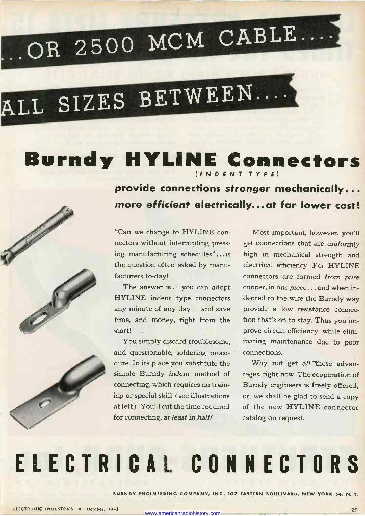
Burndy HYLINE Connectors (INDENT TYPE)
provide connections stronger mechanically... more efficient electrically... at far lower cost!
"Can we change to HYLINE con-
nectors without interrupting press-
ing manufacturing schedules" ... is
the question often asked by manu- facturers to -day!
The answer is ... you can adopt HYLINE indent type connectors any minute of any day ... and save time, and money, right from the start! .
You simply discard troublesome, and questionable, soldering proce- dure. In its place you substitute the simple Burndy indent method of
connecting, which requires no train- ing or special skill ( see illustrations at left). You'll cut the time required for connecting, at least in half!
Most important, however, you'll get connections that are uniformly high in mechanical strength and electrical efficiency. For HYLINE connectors are formed from pure copper, in one piece ... and when in- dented to the wire the Burndy way provide a low resistance connec- tion that's on to stay. Thus you im- prove circuit efficiency, while elim- inating maintenance due to poor connections.
Why not get all these advan- tages, right now. The cooperation of Burndy engineers is freely offered; or, we shall be glad to send a copy of the new HYLINE connector catalog on request.
ELECTRICAL CONNECTORS BURNDY ENGINEERING COMPANY, INC., 107 EASTERN BOULEVARD, NEW YORK 54, N. Y.
ELECTRONIC INDUSTRIES October, 1943 25 www.americanradiohistory.com
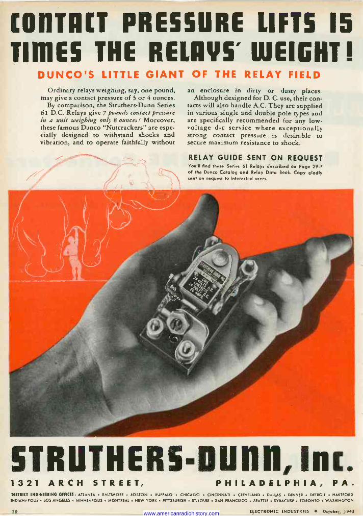
[011T11[í PRESSURE LIFTS 15
TINES THE RELAYS' WEIGHT! DUNCO'S LITTLE GIANT OF THE RELAY FIELD
Ordinary relays weighing, say, one pound, may give a contact pressure of 3 or 4 ounces.
By comparison, the Struthers -Dunn Series 61 D.C. Relays give 7 pounds contact pressure in a unit weighing only 8 ounces! Moreover, these famous Dunco "Nutcrackers" are espe- cially designed to withstand shocks and vibration, and to operate faithfully without
an enclosure in dirty or dusty places. Although designed for D. C. use, their con-
tacts will also handle A.C. They are supplied in various single and double pole types and are specifically recommended for any low - voltage d -c service where exceptionally strong contact pressure is desirable to secure maximum resistance to shock.
RELAY GUIDE SENT ON REQUEST You'll find these Series 61 Relays described on Page 29-F of the Dunco Catalog and Relay Data Book. Copy gladly sent on request to interested users.
5TRUTHER5' unn, Inc. 1321 ARCH STREET, PHILADELPHIA, P A .
DISTRICT ENGINEERING OFFICES: ATLANTA BALTIMORE BOSTON BUFFALO CHICAGO CINCINNATI CLEVELAND DALLAS DENVER DETROIT HARTFORD
INDIANAPOLIS LOS ANGELES MINNEAPOLIS MONTREAL NEW YORK PITTSBURGH ST. LOUIS SAN FRANCISCO SEATTLE SYRACUSE TORONTO WASHINGTON
26 ELECTRONIC INDUSTRIES October, 1943 www.americanradiohistory.com
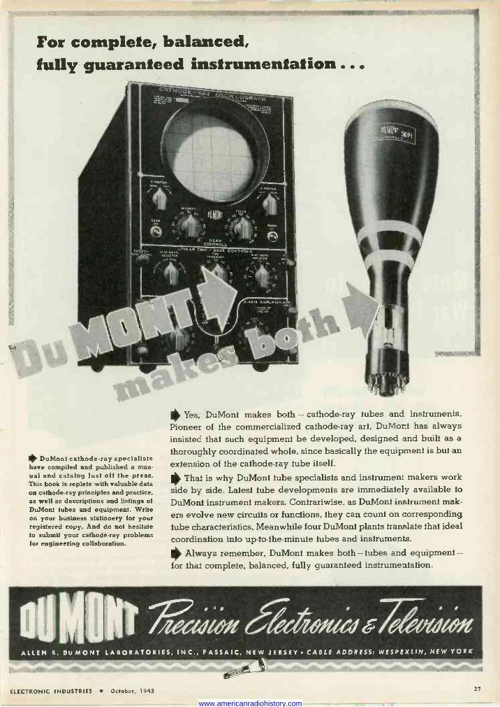
For complete, balanced, fully guaranteed instrumentation...
CATMODE- nAY Ree'. ._._
Y rosnro.
DuMont cathode-ray specialists have compiled end published a man- ual and catalog just off the press. This book is replete with valuable data on cathode-ray principles and practice. as well as descriptions and listings of DuMont tubes and equipment. Write on your business stationery for your registered copy. And do not hesitate to submit your cathode-ray problems for engineering collaboration.
- SEAN CONTROLS
LINEAR TOME - BASE CONTROLS SYNC 5.141. AL
,a wrtioi,
IN
11> Yes, DuMont makes both - cathode-ray tubes and instruments. Pioneer of the commercialized cathode-ray art, DuMont has always insisted that such equipment be developed, designed and built as a
thoroughly coordinated whole, since basically the equipment is but an extension of the cathode-ray tube itself.
I> That is why DuMont tube specialists and instrument makers work side by side. Latest tube developments are immediately available to
DuMont instrument makers. Contrariwise, as DuMont instrument mak- ers evolve new circuits or functions, they can count on corresponding tube characteristics. Meanwhile four DuMont plants translate that ideal coordination info up-to-the-minute tubes and instruments.
Always remember, DuMont makes both-tubes and equipment - for that complete, balanced, fully guaranteed instrumentation.
Mat éideyteed,747,.- ALLEN B. Du MONT LABORATORIES, INC., PASSAIC, NEW JERSEY CABLE ADDRESS: WESPEXLIN, NEW YORK
ELECTRONIC INDUSTRIES October, 1943 27
www.americanradiohistory.com
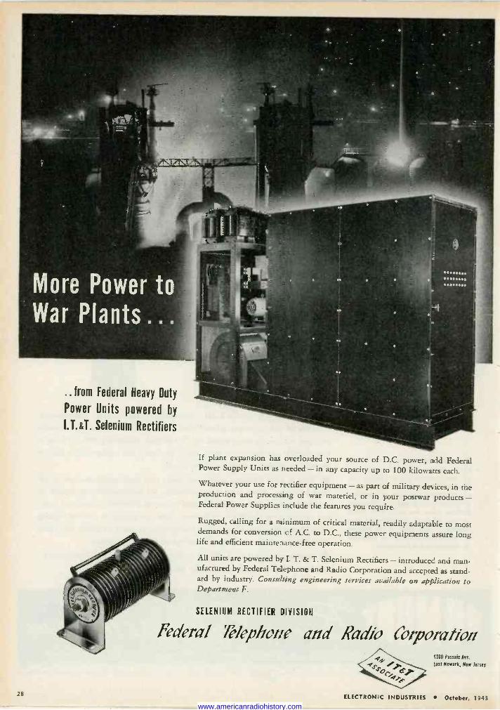
..from Federal Heavy Duty
Power Units powered by
I.T.&T. Selenium Rectifiers
If plant expansion has overloaded your source of D.C. power, add Federal Power Supply Units as needed - in any capacity up to 100 kilowatts each.
Whatever your use for rectifier equipment - as part of military devices, in the production and processing of war materiel, or in your postwar products - Federal Power Supplies include the features you require.
Rugged, calling for a minimum of critical material, readily adaptable to most demands for conversion cf A.C. to D.C., these power equipments assure long life and efficient maintenance -free operation.
All units are powered by I. T. & T. Selenium Rectifiers - introduced and man- ufactured by Federal Telephone and Radio Corporation and accepted as stand- ard by industry. Consulting engineering services available on application to Department F.
SELENIUM RECTIFIER DIVISION
Federal 78epho-=e and Nadia Corporation 000 Passaic Are.
East Newark, New Jr sey
28 ELECTRONIC INDUSTRIES ' October, 1043
www.americanradiohistory.com
1.1
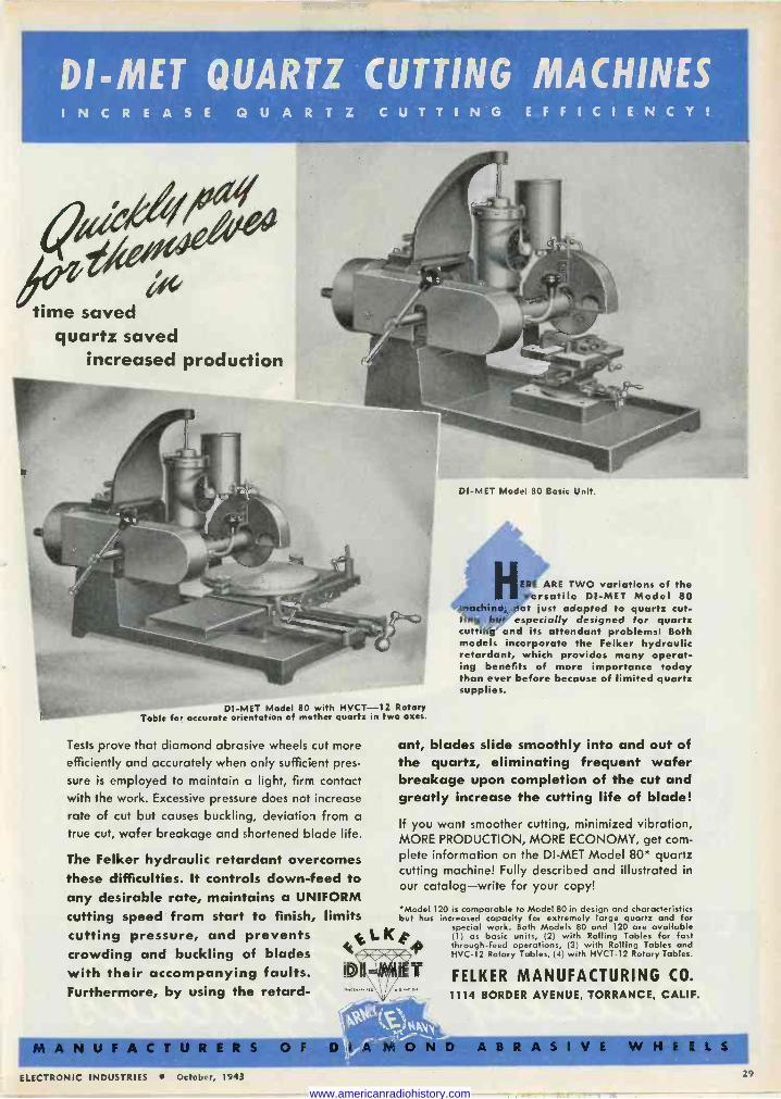
Dl -MET QUARTZ CUTTING MACHINES INCREASE QUARTZ CUTTING EFFICIENCY!
time saved quartz saved
increased production
DI -MET Model 80 with HVCT-12 Rotary Table for accurate orientation of mother quartz in two axes.
Tests prove that diamond abrasive wheels cut more efficiently and accurately when only sufficient pres-
sure is employed to maintain a light, firm contact with the work. Excessive pressure does not increase
rate of cut but causes buckling, deviation from a
true cut, wafer breakage and shortened blade life.
The Felker hydraulic retardant overcomes these difficulties. It controls down -feed to any desirable rate, maintains a UNIFORM cutting speed from start to finish, limits cutting pressure, and prevents crowding and buckling of blades with their accompanying faults. Furthermore, by using the retard -
Dl -MET Model 80 Basic Unit.
HERE ARE TWO variations of the versatile DI -MET Model 80
machine, not just adapted to quartz cut- ting We especially designed for quartz cutting and its attendant problems! Both models incorporate the Felker hydraulic retardant, which provides many operat- ing benefits of more importance today than ever before because of limited quartz supplies.
ant, blades slide smoothly into and out of the quartz, eliminating frequent wafer breakage upon completion of the cut and greatly increase the cutting life of blade!
If you want smoother cutting, minimized vibration, MORE PRODUCTION, MORE ECONOMY, get com- plete information on the DI -MET Model 80* quartz cutting machine! Fully described and illustrated in
our catalog-write for your copy!
t t Kt (1) as bask units, (2) with Rolling Tables for fast
'Model 120 is comparable to Model 80 in design and characteristics but has increased capacity for extremely large quartz and for
special work. Both Models 80 and 120 are available Ï g``ENI,
,MANUFACTURERS Olreir /[ ` D ABRASIVE WHEELS :..
through -feed operations, (3) with Rolling Tables and HVC-12 Rotary Tables, (4) with HVCT-12 Rotary Tables.
1F FELKER MANUFACTURING CO. 1114 BORDER AVENUE, TORRANCE, CALIF.
ELECTRONIC INDUSTRIES ort.,l , , 29
www.americanradiohistory.com
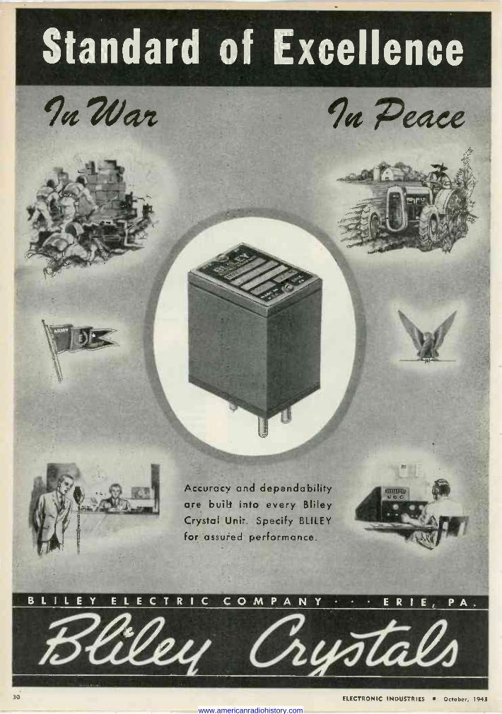
Standard of Excellence
9g Vet 9e Patee
Accuracy and dependability are built into every Bliley Crystal Unir. Specify BLILEY
for assured performance.
BLILEY ELECTRIC COMPANY ERIE, PA.
30. ELECTRONIC INDUSTRIES October, 1943
www.americanradiohistory.com
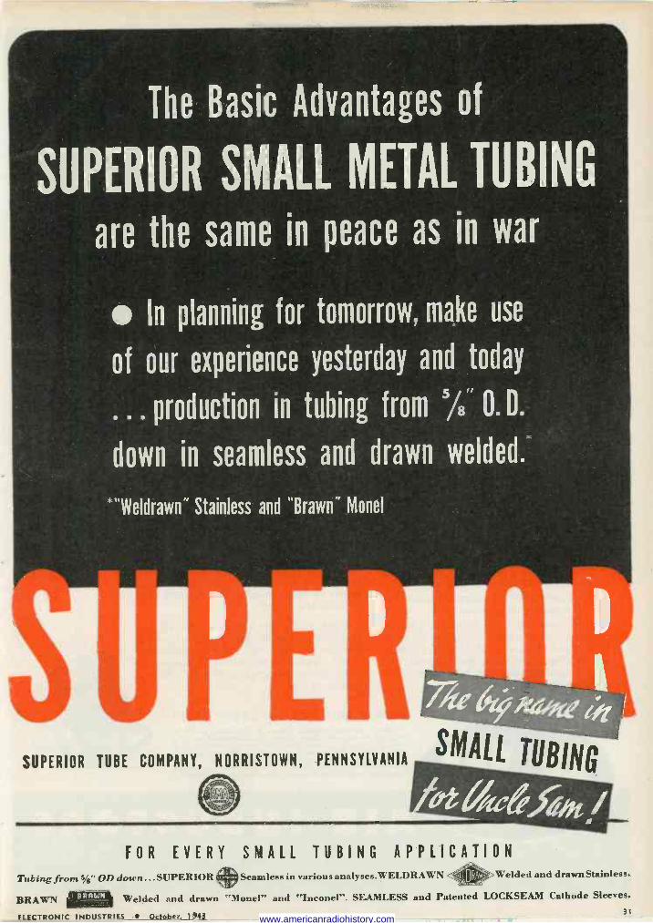
The Basic Advantages of
SUPERIOR SMALL METAL TUBING
are the same in peace as in war
In planning for tomorrow, make use
of our experience yesterday and today
. . . production in tubing from 5/8' 0. D.
down in seamless and drawn welded.
"Weldrawn" Stainless and "Brawn" Monel
SUPERIOR TUBE COMPANY, NORRISTOWN, PENNSYLVANIA SMALL
FOR EVERY SMALL TUBING APPLICATION
UBING
Tubing frore S/g" OD down ...SUPERIOR (»Seamless in various analyses.WELDRAWN ELoRAw Welded and drawn Stainless.
BRAWN giall Welded and drawn "Monel" and "Inconel". SEAMLESS and Patented LOCKSEAM Cathode Sleeves.
ELECTRONIC INDUSTRIES October, 1,43 31 www.americanradiohistory.com
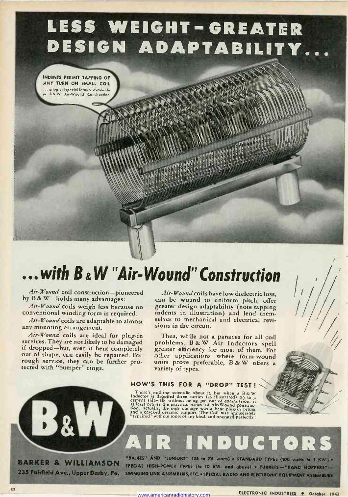
INDENTS PERMIT TAPPING OF ANY TURN ON SMALL COIL
.. a typical special feature available in B & W Air -Wound Construction
...with B &W "Air -Wound" Construction B
Air -Wound coil construction-pioneered coil by & W-holds many advantages:
Air -Wound coils weigh less because no conventional winding form is required.
Air -Wound coils are adaptable to almost any mounting arrangement.
Air -Wound coils are ideal for plug-in services. They are not likely to be damaged if dropped-but, even if bent completely out of shape, can easily be repaired. For rough service, they can be further pro- tected with "bumper" rings.
BARKER & WILLIAMSON 235 Fairfield Ave., Upper Darby, Pa.
Ai.-W'ouii coils have low dielectric loss, Air -Wound coils have low dielectric loss, can be wound to uniform pitch, offer greater design adaptability (note tapping indents in illustration) and lend them- selves to mechanical and electrical revi- sions in the circuit.
Thus, while not a panacea for all coil problems., B & W Air Inductors spell greater efficiency for most of them. For other applications where form -wound units prone preferable, B & W offers a variety of types.
HOW'S THIS FOR A "DROP" TEST ! \\ There's nothing scientific about it, but when a B & W Inductor is dropped three stories (as illustrated) on to a
cement sidewalk without being put out of commission, it at least proses the practical nature of Air -Wound construc- tion. Actually, the only damage was a bent plug-in prong and a cracked ceramic support. The Coil was immediately "repaired" without tools of any kind, and operated perfectly !
"BABIES" AND "JUNIORS" (25 to 75 watts) STANDARD TYPES (100 watts to 1 KW.) SPECIAL HIGH -POWER TYPES (to 10 KW. and above) TURRETS-"BAND HOPPERS" -- SWINGING LINK ASSEMBLIES, ETC. SPECIAL RADIO AND ELECTRONIC EQUIPMENT ASSEMBLIES
z
ELECTRONIC INDUSTRIES October, 1943 www.americanradiohistory.com
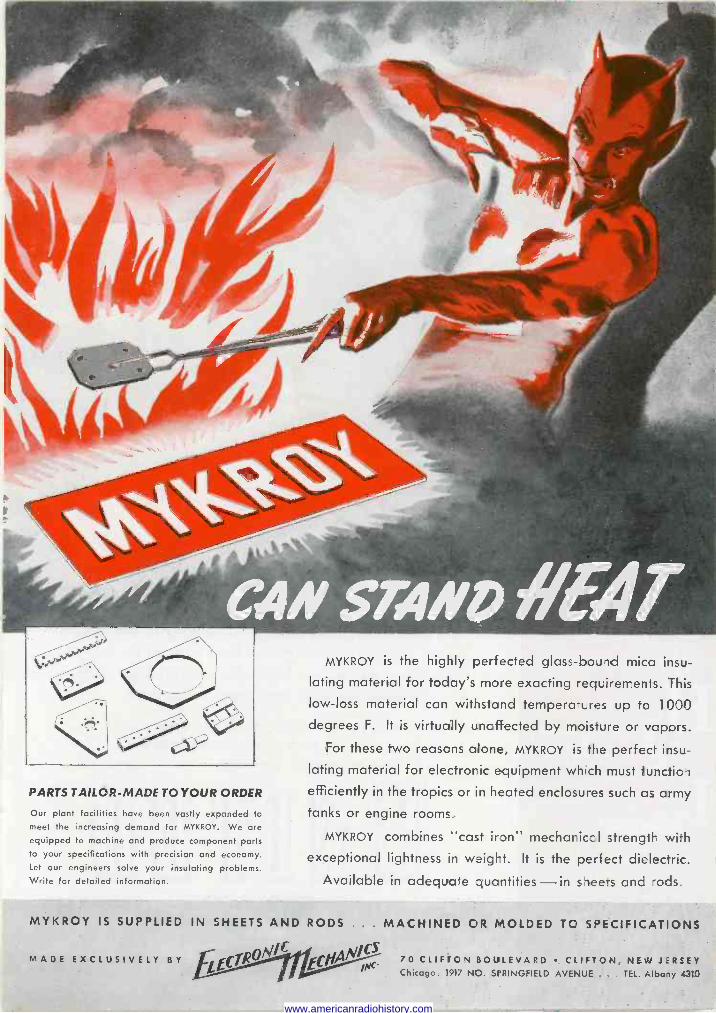
PARTS TAILOR-MADE TO YOUR ORDER
Our plant Facilities have been vastly expanded to meet the increasing demand for MYKROY. We are equipped to machine and produce component parts to your specifications with precision and economy. Let our engineers solve your insulating problems. Write for detailed information.
MYKROY is the highly perfected glass -bound mica insu-
lating material for today's more exacting requirements. This
low -loss material can withstand temperatures up to 1000 degrees F. It is virtually unaffected by moisture or vapors.
For these two reasons alone, MYKROY is the perfect insu-
lating material for electronic equipment whfich must function efficiently in the tropics or in heated enclosures such as army tanks or engine rooms.
MYKROY combines "cast iron" mechanical strength with exceptional lightness in weight. It is the perfect dielectric.
Available in adequate quantities - in sieets and rods.
MYKROY IS SUPPLIED IN SHEETS AND RODS . . . MACHINED OR MOLDED TO SPECIFICATIONS
MADE EXCLUSIVELY BY 70 CLIFTON BOULEVARD CLIFT:ON, NE.W JiERSEY Chicago: 1917 NO. SPRINGFIELD AVENUE . . . TEL. Albany 4310
www.americanradiohistory.com
mateur
rradcasting
C ommercial
iatheríijay
Army, Navy & Aviation
...and so ou, throughout the "alphabet" of boundless electronic applications
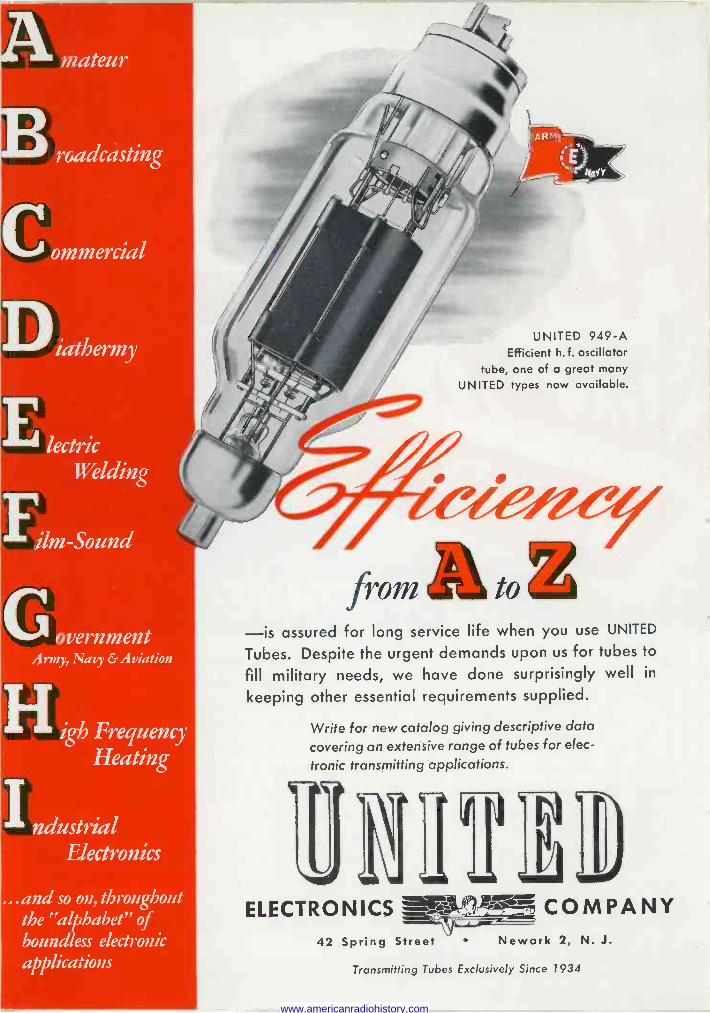
UNITED 949-A Efficient h. f. oscillator
tube, one of a great many
UNITED types now available.
fromL -is assured for long service life when you use UNITED
Tubes. Despite the urgent demands upon us for tubes to
fill military needs, we have done surprisingly well in
keeping other essential requirements supplied.
Write for new catalog giving descriptive data
covering an extensive range of tubes for elec-
tronic transmitting applications.
TIMID ELECTRONICS . COMPANY
42 Spring Street Newark 2, N. J.
Transmitting Tubes Exclusively Since 1934
www.americanradiohistory.com
t t ;ty
e n eEt trey o
fce Ge n t °` n E°t tre e6 J
t° et- e t o
°S e Pe `ty J J o s
n n
att 5
ns E Jsea Jse
;9 t
tt e oct a SQe °ò°Q yts' E°< 4oct.><
0 0
Qe , o e ° òeo :o tHe
co o 0
Got rc` 9 con c,Ec°t3.°i+,ae:l tea 4°
o,t t .9` ote bee °e5éa,C ry0 coSe e ct`
: t' t c
2.4 t
to te c
a?oP o £.o o` oae
r o tr e tc 09 e o co r
oE t`e
e :S 9
òe b° tttQ
e`s ele co oc . °oa E :9r 9 ret`
Eocr °r od
:Fp aet
E aJt ea ¢ to lye
e°o N °c o tr Ao oaL a ó P h cr a :n t c°o J`t`,J '`b%)
--t :n e cQ ó° aea a tr° e n c,
e ce e
on ctt`ess b°tte< s
tre ' cc` a; ß` et o`', ̀ en
c` tteat °t Qo
soc' ret rae%%65 JP t° P°Pe9not o<e eels °tte
ts o oe t < s a et tre IEot cJ` e< ;;ob est :`Q oser a o° e ae oe tre <e e co ceo h.9
M°` e' s< ts° t° `° a °n e ae t< s °t GJtr °:<
se co Je, reSe
e`te te9
e%ey tt tr to( AvQ co<?S.
ses <oat s`90
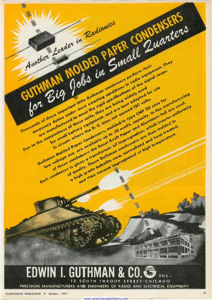
15 SOUTH THROOP STREETCHICAGO PRECISION MANUFACTURERS AND ENGINEERS OF RADIO AND ELECTRICAL EQUIPMENT
ELECTRONIC INDUSTRIES October, 1943 3'
www.americanradiohistory.com
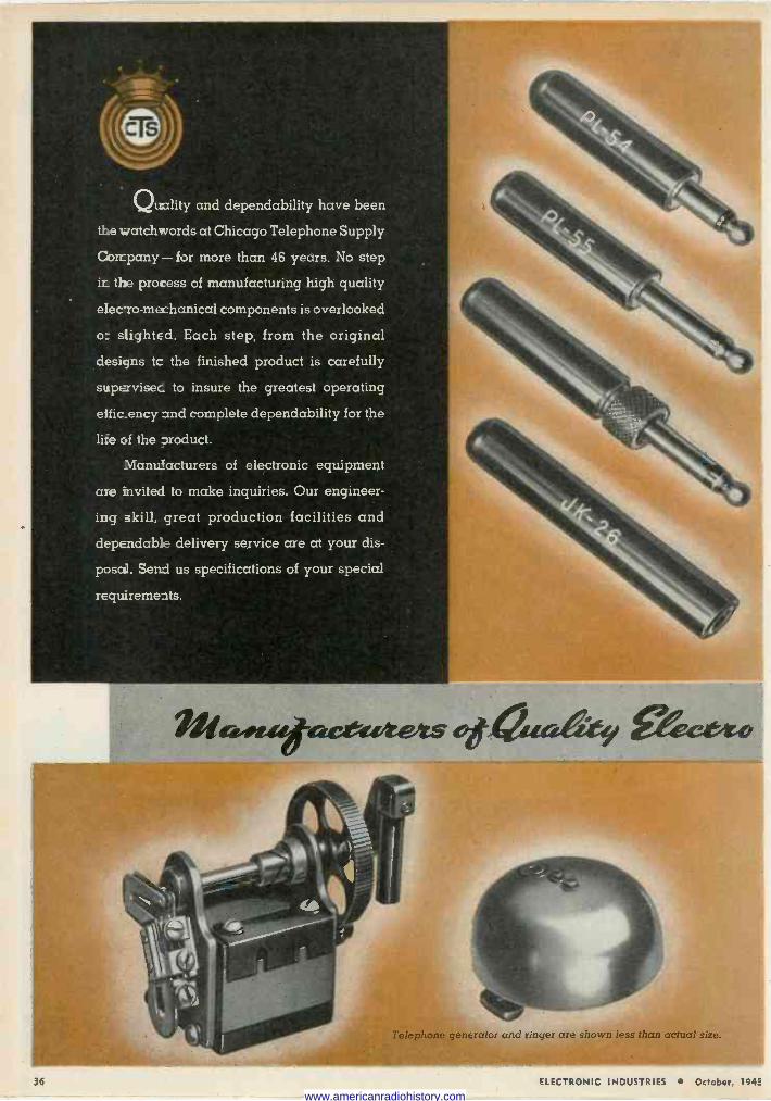
Qu xlity and dependability have been
the watchwords at Chicago Telephone Supply
Company - for more than 46 years. No step
ir_ the process of manufacturing high quality
eIec-ro-mechanical components is overlooked
o: slighted. Each step, from the original
designs tc the finished product is carefully
supe rvisec to insure the greatest operating
eific_ency and complete dependability for the
li:e :of the product.
Manufacturers of electronic equipment
are invited to make inquiries. Our engineer-
ing skill, great production facilities and
dependab:e delivery service are at your dis-
posd. Send us specifications of your special
requireme ats.
Telephone generator and ringer are shown less than actual size.
36 ELECTRONIC INDUSTRIES October, 194e
www.americanradiohistory.com
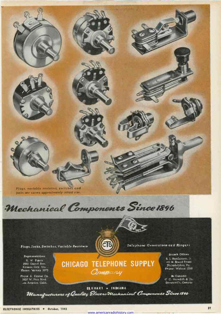
Plugs, variable resistors, switches cnd jacks are s.iown approximately actual s ze.
Flugs, licks, Switches, Variable Resisters
Represantctives R. W Farris
29O0 Gland Ave. Kansas City, Mo.
Fhone: 4ictory 307J
Frank A. Emmet Co. 2837 W. Pico Blvd. _os Angales. Calif.
Telephone Generators and Ringers
N. dig CHICAGO TELEPHONE SUPPLY
ccruipC6Y.,
Brsnch Offices
fi. 1. Hutchinson, :r. -01 A. Broad S-reet Phïadehhia, Pc.
Fhcn : Walnut 5:69
in Canada: C C. Meredith ó Co. Etreetsvile, Ontario
ELKHART * INDIANA
??lG-sueGu^tu.se.ts ogreataÌet !et.ca 1NQsc:.sue.F° C.iesypeneeotts gsrseEasts
ELECTRONIC INDUSTRIES October, 1943 37
www.americanradiohistory.com
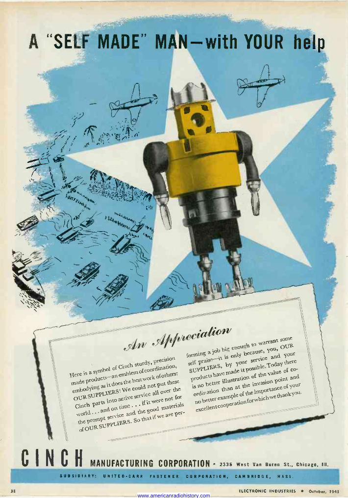
A "SELF MADE" MAN-with YOUR he
.f= , .,
p.5#141* i ii A
(
s
: i.At .}L_. i stXr!r,d*
444 t prl / Xl r`Ct
, .. 91 A
e%% G h to warrant some
a job big enough OUR
rnade
e you, forming only because,
recision it is
recto- of Cinch of coordination,
self praise--it ai by Your °service b e.Taay the o
Here is a symbol an emblem
°f coo SUPPLIERS, ruade it p value of co -
world
nowork of pothers: products e it p ss the val and
embodying as it does
We be could not puver
the these
ps no better illustration 1 át the invasion
point
OUR Stipp service all ° ordination le of the importance
o your
LIERS of for
ou arts into active ery
were n no better example rwhich.vethankY
Cinch P e'' h
if e l good materials o e tter eooperatio
th
world ... and e th g per- red
toh t he SUPPLIERS.
ppI IERS SO that if `^
esdAv
P
CINCHMANUFACTURING CORPORATION ' 2335 West Van Buren St., Chicago, III.
SUBSIDIARY: UNITE D -CA RR FASTEN ER CORPORATION, CAM B RI DG E, MASS.
38 ELECTRONIC INDUSTRIES October, 1943 www.americanradiohistory.com
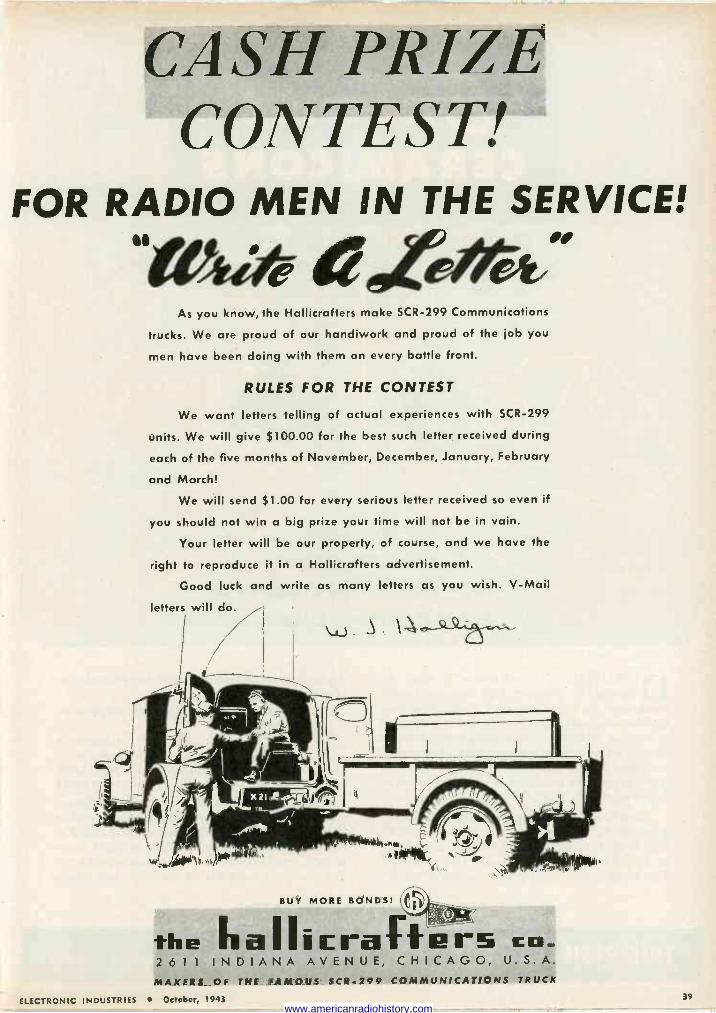
CASH PRIZE CONTEST!
FOR RADIO MEN IN THE SERVICE!
"0,41-9# dete/r9; As you know, the Hallicrafters make SCR -299 Communications
trucks. We are proud of our handiwork and proud of the job you
men have been doing with them on every battle front.
RULES FOR THE CONTEST
We want letters telling of actual experiences with SCR -299
units. We will give $100.00 for the best such letter received during
each of the five months of November, December, January, February
and March!
We will send $1.00 for every serious letter received so even if
you should not win a big prize your time will not be in vain.
Your letter will be our property, of course, and we have the
right to reproduce it in a Hallicrafters advertisement.
Good luck and write as many letters as you wish. V -Mail
letters will do.
w. 3
BUY MORE BONDS! r.a)`
*
the IlaIIicrafIIE!r5 co_ 2 6 1 1 INDIANA AVENUE, CHICAGO, U.S.A. MAKERS OF THE FAMOUS SCR -299 COMMUNICATIONS TRUCK
ELECTRONIC INDUSTRIES October, 1943 39
www.americanradiohistory.com
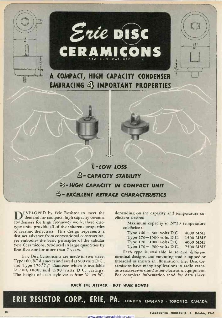
4 Elie DISC CERAMICONS
R E G . U.S. PAT. OFF.
A COMPACT, HIGH CAPACITY CONDENSER
EMBRACING j IMPORTANT PROPERTIES
li -Low Loss 2- CAPACITY STABILITY - HIGH CAPACITY IN COMPACT UNIT
- EXCELLENT RETRACE CHARACTERISTICS
15" 16
DEVELOPED by Erie Resistor to meet the demand for compact, high capacity ceramic
condensers for high frequency work, these disc - type units provide all of the inherent properties of ceramic dielectrics. This design represents a distinct advance from conventional construction, yet embodies the basic principles of the tubular type Ceramicons, produced in large quantities by Erie Resistor for more than 7 years.
Erie Disc Ceramicons are made in two sizes: Type 160,34" diameter and rated at 500 volts D.C., and Type 170,15/16' diameter which is available in 500, 1000, and 1500 volts D.C. ratings. The height of each style varies from 1/4" to 3/4",
depending on the capacity and efficient desired.
Maximum capacity in N750 coefficient:
Type 160- 500 volts D.C. Type 170-1500 volts D.C. Type 170-1000 volts D.C. Type 170- 500 volts D.C.
temperature co -
temperature
4000 MMF 1500 MMF 4000 MMF 7500 MMF
Each type is available in several different terminal designs, and mounting stud is tapped or threaded as shown in illustration. Erie Disc Ce- ramicons have many applications in radio trans- mitters, receivers, and other electronic equipment. For complete information send for data sheet.
BACK THE ATTACK-BUY WAR BONDS
ERIE RESISTOR CORP., ERIE, PAe LONDON, ENGLAND TORONTO, CANADA.
40 ELECTRONIC INDUSTRIES October, 1943 www.americanradiohistory.com
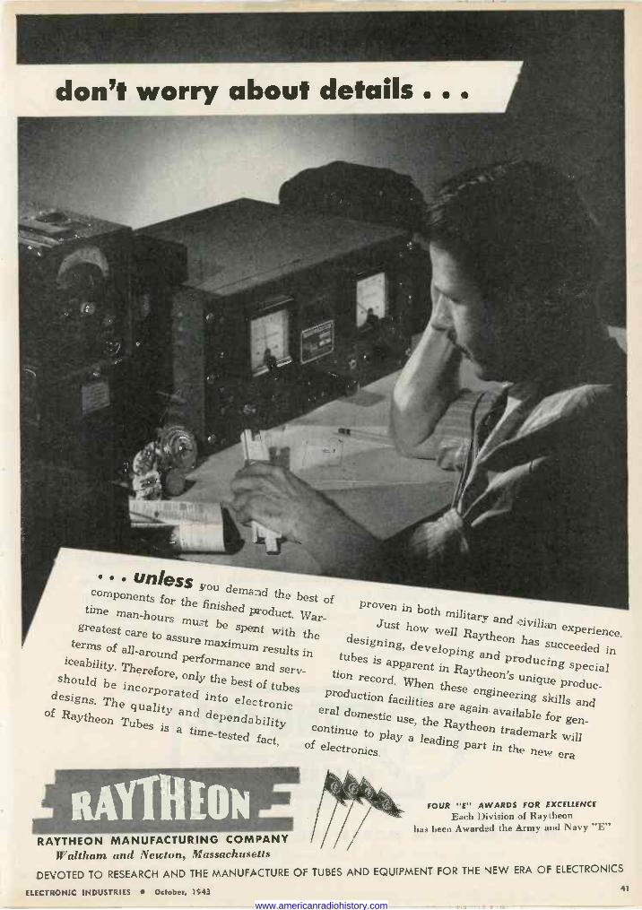
don't worry about details .. .
Unless you demand components for the finished
the best of proven time man-hours product. in both military and iviliart experience. greatest care spent with the well Raytheon to assure maximum
Just has succeeded
in terms of all- results in g, developing and
icerms around perform tubes is a producing Y. Therefore ante and sere- apparent in Raytheon' special
should , only the best of tion record. When s unique
be i tubes theseproduc- d h
incorporated into production facilities
engineering gns. The electronic skills and
en - quality eral do
are again available for of Raytheon TubesY and dependability domestic use, the continue to Raytheon trademark is a time_tested
fact, play a lea will of electronics. ding part in the new era
FOUR "E" AWARDS FOR EXCELLENCE
Each Division of Raytheon has been Awarded the Army and I\avy "E"
RAYTHEON MANUFACTURING COMPANY Waltham and Newton, Massachusetts
DEVOTED TO RESEARCH AND THE MANUFACTURE OF TUBES AND EQUIPMENT FOR THE NEW ERA OF ELECTRONICS
ELECTRONIC INDUSTRIES October, 1943 41
www.americanradiohistory.com
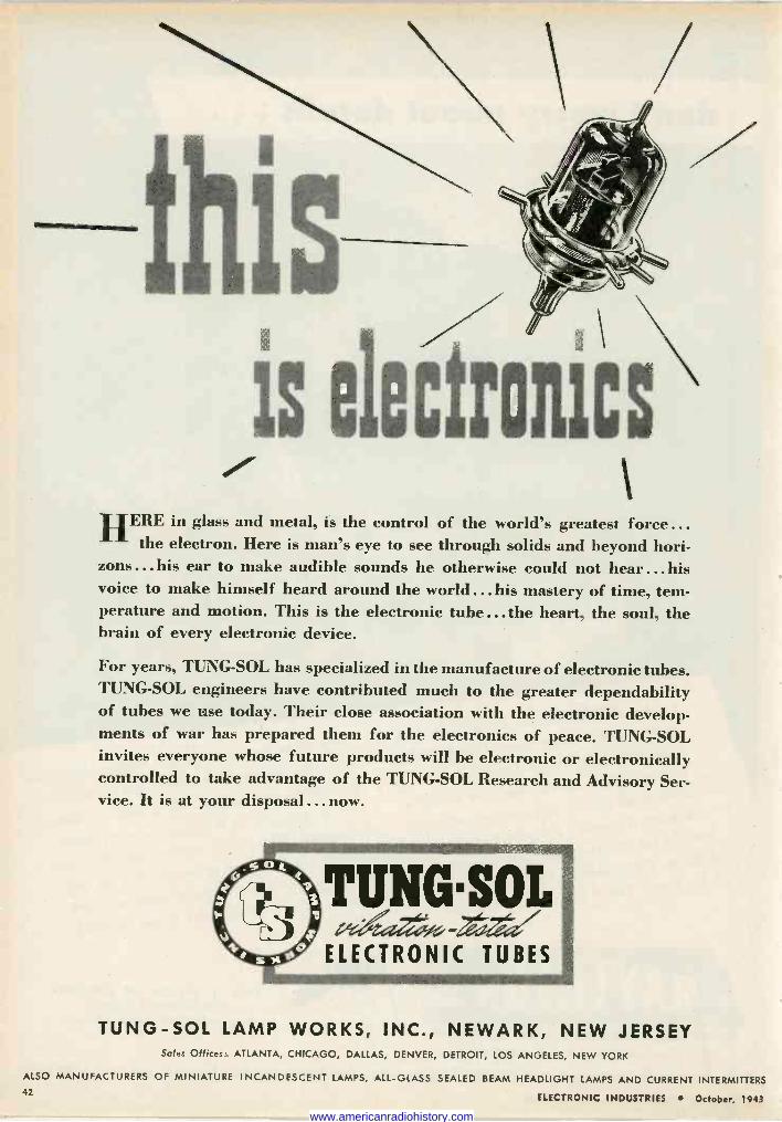
this is ele(ronics
HERE in glass and metal, is the control of the world's greatest force... the electron. Here is man's eye to see through solids and beyond hori-
zons... his ear to make audible sounds he otherwise could not hear ...his voice to make himself heard around the world... his mastery of time, tem- perature and motion. This is the electronic tube ...the heart, the soul, the brain of every electronic device.
For years, TUNG-SOL has specialized in the manufacture of electronic tubes. TUNG-SOL engineers have contributed much to the greater dependability of tubes we use today. Their close association with the electronic develop- ments of war has prepared them for the electronics of peace. TUNG-SOL invites everyone whose future products will be electronic or electronically controlled to take advantage of the TUNG-SOL Research and Advisory Ser- vice. It is at your disposal ...now.
TUNG-SOL LAMP WORKS, INC., NEWARK, NEW JERSEY Sales Offices: ATLANTA, CHICAGO, DALLAS, DENVER, DETROIT, LOS ANGELES, NEW YORK
ALSO MANUFACTURERS OF MINIATURE INCANDESCENT LAMPS, ALL -GLASS SEALED BEAM HEADLIGHT LAMPS AND CURRENT INTERMITTERS 42
ELECTRONIC INDUSTRIES October, 1943
www.americanradiohistory.com
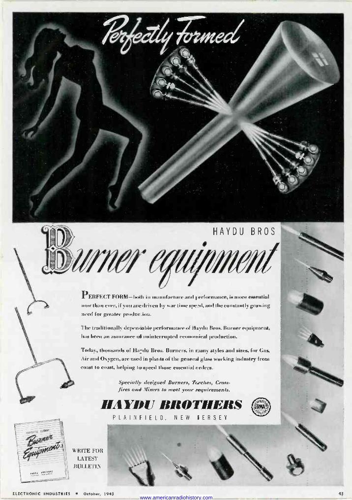
PERFECT FORM-bode in manufacture and F-erformance, is more essential
now than ever, if you are driven by war time sped, and the constantly growing
need for greater produe ' .
The traditionally dependable performance of Haydn Bros. Burner equipment, has been an assurance oh uninterrupted economical production.
Today, thousands of Ha -du Bros. Burners, in t tany styles and sizes, for Gas,
Air and Oxygen, are used in plants of the general glass working industry from coast to coast, helping to speed those essential orders.
Specially designed Burners, Trrches, Cross - fires and Mixers to meet your requirements.
HAYDU BROTHERS PLAINfIELD, NEW IERSEY
WRITE FOR
LATEST
BULLETIN
ELECTRONIC INDUSTRIES October, 1943 43 www.americanradiohistory.com
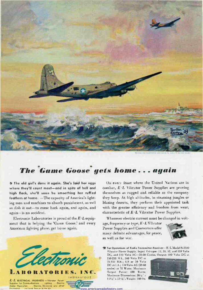
s The Game Goose gets home ... again The old girl's done it again. She's laid her eggs
where they'll count most-and in spite of hell and
high flack, she'll soon be smoothing her rufflled
feathers at home. -The capacity of America's fight ing men and machines to absorb punishment, as well
as dish it out-to come back again, and again, and again-is no accident.
Electronic Laboratories is proud of the EL equip. ment that is helping the 'Game Goose,' and every American fighting plane, get home again.
LABORATORIES. INC. INDICNAFOLIS
E L ELECTRICAL PRODUCTS - Vibrator Power Supplies for Communications ....ighting ... Electic Motor Operation . . Electric, Electronic and otter F,...,.....e.., nn I noel S ,, nr in the Mr.
On every front where the United Nations are in combat, EL Vibrator Power Supplies are proving themselves as rugged and reliable as the company they keep. At high altitudes, in steaming jungles or
blazing deserts, they perform their appointed task with the greater efficiency and freedom from wear, characteristic of EL Vibrator Power Supplies.
Wherever electric current must be changed in volt- age, frequency or type, E L Vibrator Power Supplies and Converters offer many definite advantages, for peace, as well as for war.
* For Operations of Radio Transmitter -Receiver -E L Model S-1200 Vibrator Power Supply. Input Voltages: 12, 24, 32, and 110 Volts DC, and 110 Volts AC -50-60 Cycles; Output: 600 Volts DC at 150-250 MA., 300 Volts DC at 75-150 MA.; 6-8 or 10 Volts DC at 1 A.; 110 Volts AC (50-60 cycles) at 75 Watts. Maximum Output Power: 280 Watts;
l aximum Dimensions: 2611'6' x
1 ISI, "x 13874"; Weight: 1601bs.
www.americanradiohistory.com

Serving the Air Routes of the Work!
...TODAY and TOMOR R O W On established passenger and cargo airlines, as well as on
military missions, dependable communications are vital.
Wilcox Aircraft Radio, Communication Receivers, Trans-
mitting and Airline Radio Equipment have served leading
airlines for many years ... and while, today, Wilcox facil-
ities are geared to military needs, the requirements of the
commercial airlines likewise are being handled. Look to
Wilcox for leadership in dependable communications !
ELECTRONIC INDUSTRIES October, 1943
WILCOX ELECTRIC COMPANY
Quality Manufacturing of Radio Equipment
14th & Chestnut Kansas City, Mo.
45
www.americanradiohistory.com
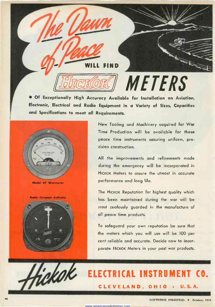
Of Exceptionally High Accuracy Available for Installation on Aviation, Electronic, Electrical and Radio Equipment in a Variety of Sizes, Capacities
and Specifications to meet all Requirements.
New Tooling and Machinery acquired for War
Time Production will be available for these
peace time instruments assuring uniform, pre-
cision construction.
All the improvements and refinements made
during the emergency will be incorporated in
HICKOK Meters to assure the utmost in accurate
performance and long life.
The HICKOK Reputation for highest quality which
has been maintained during the war will be
most zealously guarded in the manufacture of
all peace time products.
To safeguard your own reputation be sure that
the meters which you will use will be 100 per
cent reliable and accurate. Decide now to incor-
porate HICKOK Meters in your post war products.
ELECTRICAL INSTRUMENT CO.
CLEVELAND, OHIO U.S.A.
46 ELECTRONIC INDUSTRIES October, 1943
www.americanradiohistory.com
1F,
a, E a ó
as O Ó a4-,, 4. m
sa'i O á c a ,r) Q.
4) o ú
N
y 3 b O p w o íu. Vi f x_Ñ M cG d b0
2 '.i
G
~ o
a Ú 93 O w x v C1 M O
et 5 m
Ga :
t 3 - a ' m o0
a 9 .5 .o
a w b º CD V w u 'd ai L
.y O o
CO a% ÿ p Ó ó'
G . o P.
ú M b
au+
'd y zit., L b u ÿ 00 CS
ó v.o.y 'a Il
K a C a~+
D ' E v á 3x
ó
Ñ
2'8 ,.zó
. y á óti .._r g ; . 3 ° 0 r * el. cyo. ÿ m á'áÑv .flcöwi 43) o _° a
CO° ai ái
ß G yu y ix +' caQ W a_ , a W o
o N e a Ó e . u ó Gx.a o.
«5 _ v,bi) G á w m =" ya3ß+ O tOA O H C: d +' O H F . V U
W a' v E' ?'5;; ,;a o moon ° O O E. 0" E c .r a G m a a g m g a
v ó'wÓ C4 3 re °' P, o w d ' r-
cya`..W vy, y V °' G" w b P+
Ñ Ñ a"i -" aî wH de :0 óg , cà G O , V 0 "cs ß ÿE ri *5 :á WcMiW 0 Loki e .M+ y O ygÿ `°;ou =M cC}
Wb Ó ,Ó áGi+7 aeearl u F f. Ñ+ _ 2y. u 7+ A u+ w w+' ó td) g Or3 cd am ° º w ` a a áp "ß á ẠJ "' W
O Ñ `" N > g :72...5 u 'Ñ -18
U w 0 a w Ú o W W b0 4 Á "e e vb e. F- : á U ' W
- . e>, ,a.-.5 .x :w xpHa áº' a W i+ (C Ew - r.1
cC`+.. m cdwó>
J
H
W a.
m
ELECTRONIC INDUSTRIES October, 1943 47
www.americanradiohistory.com
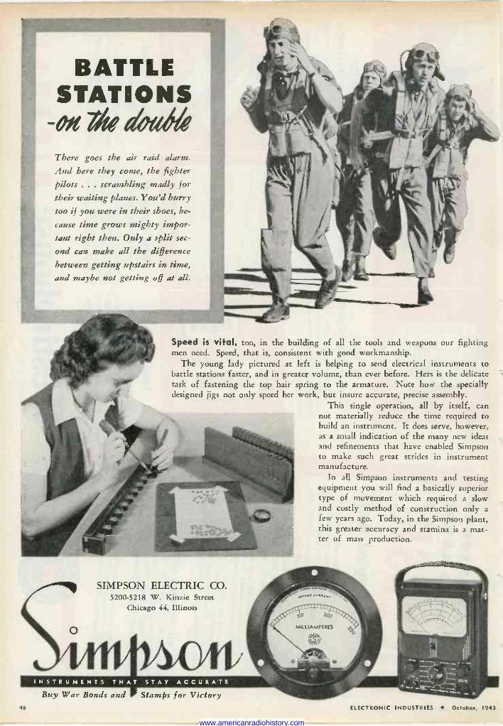
BATTLE STATIONS
-OJL 744 deide There goes the air raid alarm.
And here they come, the fighter pilots ... scrambling madly for their waiting planes. You'd hurry too if you were in their shoes, be-
cause time grows mighty impor- tant right then. Only a split sec-
ond can make all the difference
between getting upstairs in time, and maybe not getting off at all.
Speed is vital, too, in the building of all the tools and weapons our fighting men need. Speed, that is, consistent with good workmanship.
The young lady pictured at left is helping to send electrical instruments to battle stations faster, and in greater volume, than ever before. Hers is the delicate task of fastening the top hair spring to the armature. Note how the specially designed jigs not only speed her work, but insure accurate, precise assembly.
This single operation, all by itself, can not materially reduce the time required to build an instrument. It does serve, however, as a small indication of the many new ideas and refinements that have enabled Simpson to make such great strides in instrument manufacture.
In all Simpson instruments and testing equipment you will find a basically superior type of movement which required a slow and costly method of construction only a few years ago. Today, in the Simpson plant, this greater accuracy and stamina is a mat- ter of mass production.
SIMPSON ELECTRIC CO. 5200-5218 W. Kinzie Street
Chicago 44, Illinois
INSTRUMENTS THAT STAY ACCURATE Buy War Bonds and Stamps for Victory
48 ELECTRONIC INDUSTRItS October, 1943
www.americanradiohistory.com
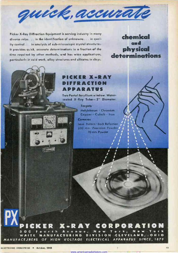
chemical and
physical determinations
Picker X -Ray Diffraction Equipment is serving industry in many
diverse roles .. in the identification of unknowns . in qual-
ity control in analysis of sub -microscopic crystal structures.
It provides quick, accurate deterrriratiors in a fraction o the
time requi-ed by other methods, and has wice applicatcns,
particularly it co c work, alloy struct.ires and silicates in cic ys.
PICKER X-RAY DIFFRACTION APPARATUS Two Portal Ber+Ilium window. Water- ceoled X -Ray Tube - 2" Diameter.
Targets Mol)bdenurr Chromium Capper Cobalt Iron
Carneras
Laue- Patten Bock Reflect
;00 mm. Precision Powd 70 rnn. Powder
3 0 0 Fourth A v e n u e, New Y o r k, New York WAITE MANUFACTURING DIVISION CLEVELAND, OHIO
MANUFACTJRERS OF HIGH VOLTAGE ELECTRICAL APPAQATL'S SINCE: 1879
ciLECTRONIC INDUSTRIES October, 1943 49
www.americanradiohistory.com
N01V3 TYPES Of roeir
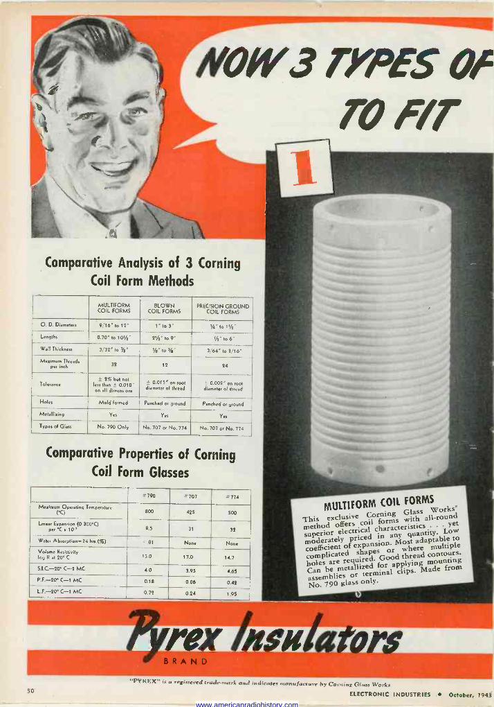
Comparative Analysis of 3 Corning
Coil Form Methods
MULTIFORM COIL FORMS
BLOWN COIL FORMS
PRECISION GROUND COIL FORMS
O. D. Diameters 9/16" to 12" 1" to 3" 1/4" to 11/4"
Lengths 0.70' to 101/2" 21" to 9" y2" to 6"
Wall Thickness 3/32° to 7/e" s/o" to 3/e" 364" to 3/16"
Maximum Threads per inch 32 12 24
Tolerance ± 2% but not
less then ± 0.010" on all dimensions
- 0.015" on root diameter of thread
0.002" on root diameter of thread
Holes Mold formed Punched or ground Punched or ground
Metallizing Yes Yes Yes
Types of Glass No. 790 Only No. 707 or No. 774 No.707 or No. 774
Comparative Properties of Corning
Coil Form Glasses
= 790 = 707 =774
Maximum Operating Temperature (°C) 800 425 500
Linear Expansion (0.300°C) per °C x 10-1 8.5 31 32
Water Absorption -24 hrs.(ó) <.01 None None
Volume Resistivity logg at 20°C 13.0 17.0 14.7
S.I.C.-20° C-1 MC 4.0 3.95 4.65
P.F.-20° C-1 MC 0.18 0.06 0.42
L.F.-20 C-1 MC 0.72 0.24 1.95
MULTIFORM COIL FORMS
This exclusive Corning Glass Works'
method offers coil forms with all-round
superior electrical characteristics y. Lyet ow moderately priced in any q ptable w coefficient of expansion. Most t ada multiple
to
complicated shapes holes are required. Good thread conto
ououng Can he metallized for applying
assemblies terminal clips. Made from
No. 790glass
ask a ors 50
"PYREX" is a registered trade -mark and indicates manufacture by Corning Glass Works
ELECTRONIC INDUSTRIES October, 1943
www.americanradiohistory.com
1111.11111011
CORN/NG CO/I FORMS (VERY fifED f
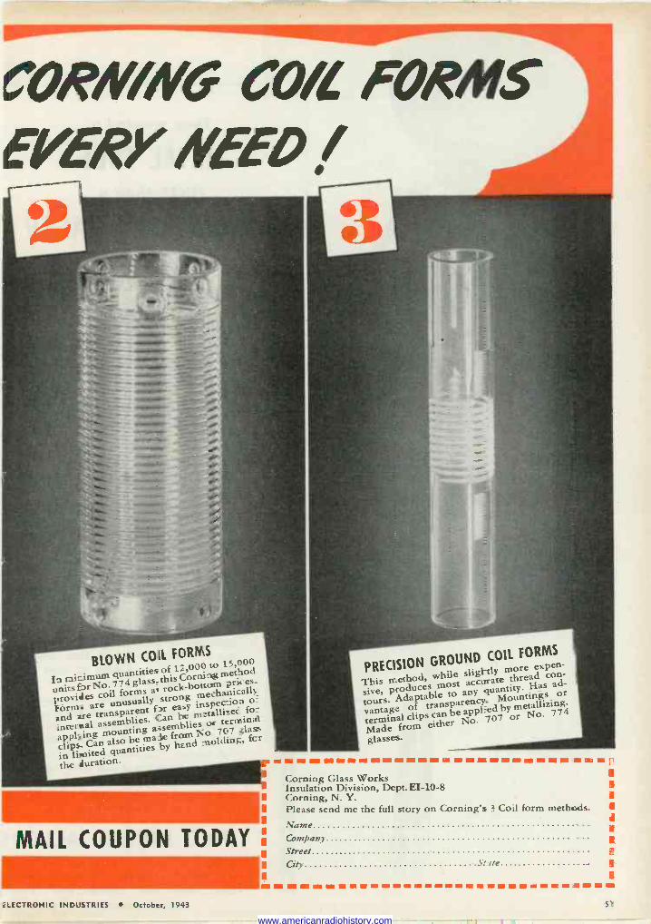
BLOWN COIL FORMS
b minimum quantities of 17,000 to 15,000
lass, this Corning method pairs provides
No. 8 t rock -bottom° prices.
are coil forms a strong mechanically.
Forme unusually inspeC=ion and ae transparent fir easy metallisec for
assemblies. aCan emblies_oc terminal
clips_ i s_ be
No 707 glass
clips- Can als ie byfh° ñ _nolding, fcr
in limited quantities the duration. n
MAIL COUPON TODAY
PRECISION GROUND COIL FORMS
This method, while slightly threadore e con-
tour, producestable mosto any quantity. Has ad-
vantage Adaptable Mountings or
ttentage of transparency. metallizing.
Madef clips can br app or No. 774
from either No.
glasses.
Corning Glass Works Insulation Division, Dept. EI -10-8 Corning, N. Y. Please send me the full story on Corning's 3 Coil form methods. I Name Company ...
Street e
City Seite II
,i
3
ELECTRONIC INDUSTRIES October, 1943 51
www.americanradiohistory.com
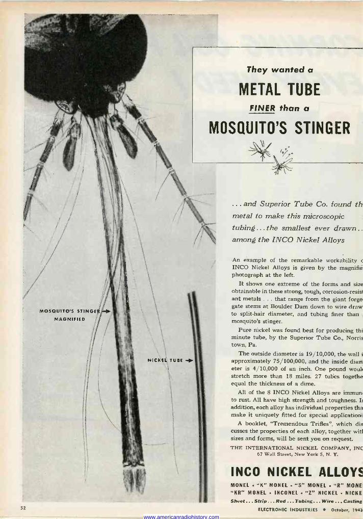
MOSQUITO'S STINCiE12,..41
MAGNIFIED
NICKEL TUBE
They wanted a
METAL TUBE FINER than a
MOSQUITO'S STINGER
... and Superior Tube Co. found th metal to make this microscopic tubing... the smallest ever drawn . .
among the INCO Nickel Alloys
An example of the remarkable workability c
INCO Nickel Alloys is given by the magnifie photograph at the left.
It shows one extreme of the forms and size obtainable in these strong, tough, corrosion -resist ant metals ... that range from the giant forge. gate stems at Boulder Dam down to wire draw. to split -hair diameter, and tubing finer than mosquito's stinger.
Pure nickel was found best for producing thi minute tube, by the Superior Tube Co., Norris town, Pa.
The outside diameter is 19/10,000, the wall i approximately 75/100,000, and the inside diam eter is 4/10,000 of an inch. One pound wouli stretch more than 18 miles. 27 tubes togethe equal the thickness of a dime.
All of the 8 INCO Nickel Alloys are immun. to rust. All have high strength and toughness. Ii addition, each alloy has individual properties tha make it uniquely fitted for special application;
A booklet, "Tremendous Trifles", which dis cusses the properties of each alloy, together witl sizes and forms, will be sent you on request. THE INTERNATIONAL NICKEL COMPANY, INC
67 Wall Street, New York 5, N. Y.
INCO NICKEL ALLOYS MONEL "K" MONEL "S" MONEL . "R" MONE
"KR" MONEL INCONEL "Z" NICKEL NICKE Sheet...Strip ... Rod ... Tubing ... Wire ... Casting
ELECTRONIC INDUSTRIES October, 1943 52
www.americanradiohistory.com
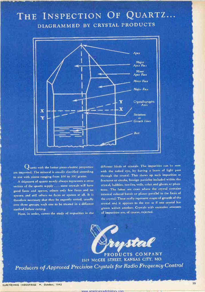
THE INSPECTION OF QUARTZ... DIAGRAMMED BY CRYSTAL PRODUCTS
X Y
Y 111M1 111.11111
Apex
Major Apex Face
Minor Apex Face
Minor Face
Major Face
Crystallographic Axes
Striations or
Growth Lines
Butt
Quartz with the better piezo-electric properties
are imported. The mineral is usually classified according
to size with pieces ranging from 100 to 300 grams.
A shipment of quartz nearly always represents a cross
section of the quartz supply ... some crystals will have
good faces and apexes, others only few faces and no
apexes, and still others no faces or apexes at all. It is
therefore necessary that they be expertly sorted, usually
into three groups, each one to be treated in a different
method before cutting. Next, in order, comes the study of impurities in the
different kinds of crystals. The impurities can be seen
with the naked eye, by having a beam of light pass
through the crystal. This shows up such impurities as
fractures or cracks, foreign particles included within the
crystal, bubbles, needles, veils, color and ghosts or phan-
toms. The latter are cases where the crystal contains
internal colored bands or planes parallel to the faces of
the crystal: These really represent stages of growth of the
crystal and it appears to the eye as if one crystal has
grown within another. Crystals with excessive amounts
of impurities are, of course, rejected.
*et." PRODUCTS COMPANY
1519 McCEE STREET. KANSAS CITY. MO.
Producers of Approved Precision Crystals for Radio Frequency Control
ELECTRONIC INDUSTRIES ' October, 1943 53
www.americanradiohistory.com
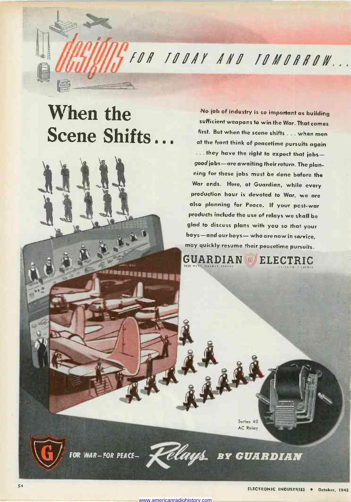
fOf f00ify if! 70110í700GY...
When the Scene Shifts.
)) )) n
FOR WAR -JOR PEA CE-
No job of industry is so important as building sufficient weapons to win the War. That comes
first. But when the scene shifts ... when men at the front think of peacetime pursuits again ... they have the right to expect that jobs- good jobs-are awaiting their return. The plan- ning for these jobs must be done before the
War ends. Here, at Guardian, while every production hour is devoted to War, we are
also planning for Peace. If your pcst-war products include the use of relays we shall be
glad to discuss plans with you so that your boys-and our boys- who are now in service,
may quickly resume their peacetime pursuits.
GUARDIAN ELECTRIC
54 ELECTRONIC INDUSTRIES October, 1943
www.americanradiohistory.com
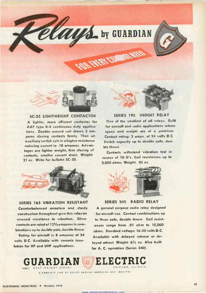
SC -25 LIGHTWEIGHT CONTACTOR
A lighter, more efficient contactor for AAF type B-4 continuous duty applica- tions. Double wound coil draws 2 am- peres closing contacts firmly. Then an
auxiliary switch cuts in a higher resistance
reducing current to .18 amperes. Advan- tages are lighter weight, firm closing of
contacts, smaller current drain. Weight:
21 oz. Write for bulletin SC -25.
SERIES 165 VIBRATION RESISTANT
Counterbalanced armature and sturdy
construction throughout give this relayan
unusual resistance to vibration. Silver
contacts are rated at 121/2 amperes in com-
binations up to double pole, double throw.
Rating for aircraft is 8 amperes at 24
volts D.C. Available with ceramic insu-
lation for HF and UHF applications.
GUARDIAN 1622-L WEST WALNUT STREET
A COMPLETE LINE OF RELAYS SERVING AMERICAN WAR INDUSTRY
SERIES 195 MIDGET RELAY
One of the smallest of all relays. Built
for aircraft and radio applications where
space and weight are at a premium.
Contact rating: 2 amps. at 24 volts D.C.
Switch capacity up to double pole, dou-
ble throw.
Contacts withstand vibration test in
excess of 10 G's. Coil resistances up to
2,000 ohms. Weight: .85 oz.
SERIES 345 RADIO RELAY
A general purpose radio relay designed
for aircraft use. Contact combinations up
to three pole, double throw. Coil resist-
ances range from .01 ohm to 15,000
ohms. Standard voltage: 16-32 volts D.C.
Available with delayed release or de-
layed attract. Weight: 61/2 oz. Also built
for A. C. operation (Series 340).
ELECTRIC CHICAGO, I L L I NOI S
ELECTRONIC INDUSTRIES October, 1943 55
www.americanradiohistory.com
In the interests of hundreds of engineers, de- signers, and production executives, to whom better coil and flat springs are of vital impor- tance, Instrument Specialties Company is plan- ning a comprehensive exhibit of "Micro -proc-
essed" beryllium copper springs and engineering data-to be shown at the National Metal Con- gress, Room 713, Palmer House, Chicago, from October 18th through the 22nd.
"Micro -processed" beryllium copper springs are setting new standards for spring design . and performance. In the past nine months, Instrument Specialties has had innumerable requests for detailed information on the met- allurgical, design, physical and electrical properties made pos-
sible by this process. Therefore, we are as-
sembling under one roof in Chicago, the best informed members of our staff, who will be pleased to discuss with you any phase of Micro - processed springs and their most effective use.
The metallurgical director, chief design engi- neer, and others of the Instrument Specialties organization will be in attendance, backed up by technical information of real value to users of springs. This is our cordial invitation for you and your associates to make it a point to
get at first hand the exceptional story of "Micro -processed" beryllium copper springs.
Room 713, Palmer House, Chicago, October 18th to the 22nd.
INSTRUMENT SPECIALTIES CO., INC.
DEPT. E-2, LITTLE FALLS, NEW JERSEY
ELECTRONIC INDUSTRIES October, 1943
www.americanradiohistory.com
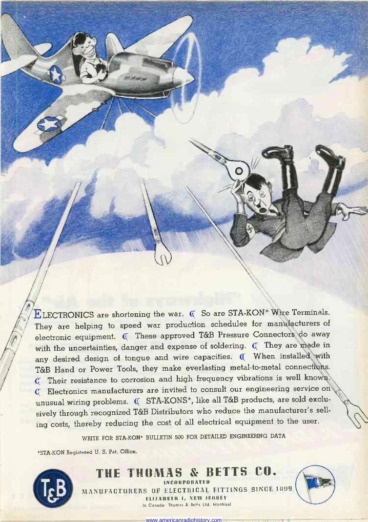
ELECTRONICS are shortening the war. CC So are STA-KON * Wìçe Terminals.
They are helping to speed war production schedules for malit cturers of
electronic equipment. Q These approved T&B Pressure Connectors o away
with the uncertainties, danger and expense of soldering. Q They are de in
any desired design of tongue and wire capacities. Q When installe ith
T&B Hand or Power Tools, they make everlasting metal -to -metal connect'
Q Their resistance to corrosion and high frequency vibrations is well kno
Q Electronics manufacturers are invited to consult our engineering service on
unusual wiring problems. Q STA-KONS*, like all T&B products, are sold exclu-
sively through recognized T&B Distributors who reduce the manufacturer's sell-
ing costs, thereby reducing the cost of all electrical equipment to the user.
WRITE FOR STA-KON* BULLETIN 500 FOR DETAILED ENGINEERING DATA
°STA-KON Registered U. S. Pat. Office.
THE THOMAS & BETTS CO. INCORPORATED
MANUFACTURERS OF ELECTRICAL FITTINGS SINCE 1899 ELIZAIIETH 1, NEW JERSEY
In Canada Thomas & Betts Ltd. Montreal
www.americanradiohistory.com
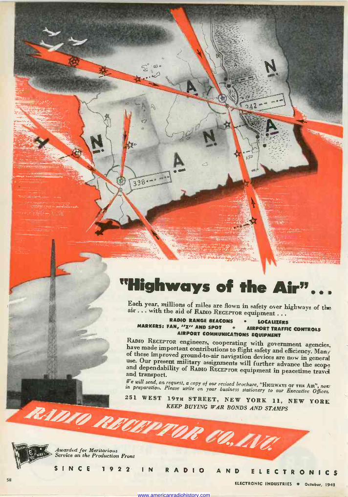
"Highways of the Air" .. . Each year, millions of miles are flown in safety over highways of the air ... with the aid of RADIO RECEPTOR equipment .. .
RADIO RANGE BEACONS LOCALIZERS MARKERS: FAN, "Z" AND SPOT AIRPORT TRAFFIC CONTROLS
AIRPORT COMMUNICATIONS EQUIPMENT RADIO RECEPTOR engineers, cooperating with government agencies, have made important contributions to flight safety and eficency. Man v of these improved ground -to -air navigation devices are now in general use. Our present military assignments will further advance the scope and dependability of RADIO RECEPTOR equipment in peacetime travel and transport. We will send, on request, a copy of our revised brochure, "HIGHWAYS OF THE Am", nor/ in preparation. Please write on your business stationery to our Executive Offices. 251 WEST 19TH STREET, NEW YORK 11, NEW YORK
KEEP BUYING WAR BONDS AND STAMPS
Awarded for Meritorious Service on the Production Front
SINCE 1 9 2 2 IN RADIO AND ELECTRONICS ELECTRONIC INDUSTRIES October, 1943
se
www.americanradiohistory.com
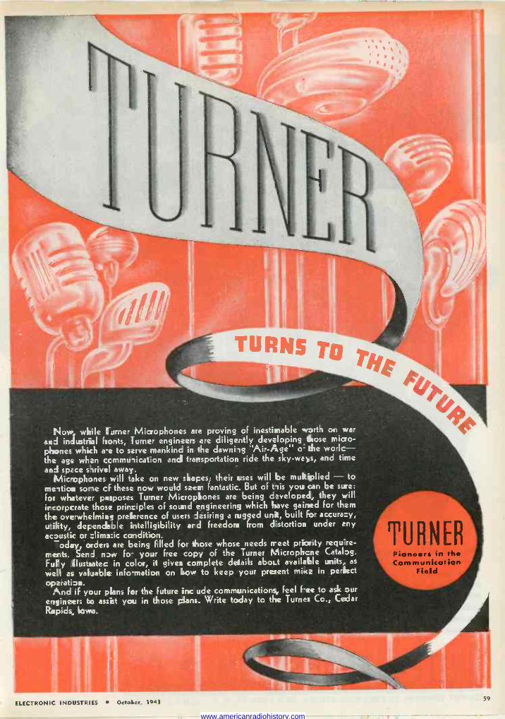
Now, while turner Microphones are proving of inestimable worth on war
and industrial hunts, Turner engineers are diligently developingthose micro- phones which ae to serve mankinc in the dawniig Air -Age o the worlc- the age when ccmmu,icat:on and trarsportation ride the sky -ways, and time
and space swivel away. Microphones will take on new shapes; their uses will be multiplied - to
me-ition sone cf these now would seem fantastic. But of tiis you can be sure:
for whatever purposes Turner Microphones are being developed, they will ircorperate those principles of sound engineering which have gained for them
the overwhelming pre(ierence of users desiring a rugged unit, built for accura:y, utility, deFendmole intelligibility and freedori from distortion under any
acoustic or clima:ic condition. oday, order. are being filled for those whose needs rreet priority require-
rrents. Send now fo- your free copy of the Turner Microphone Catalog.
Fully Illustsatec in color, it gives complete details aboLt available units, as
well as valuable info-mation on how to keep your present mice in perfect
operati on. And if your plans for the future irrc ude communications, feel fee to ask our
engineers to assist you in those plans. Write today to the Turner Co., Cedar
Rapids. Iowa.
ELECTRONIC INDUSTRIES October, 1943
TURNER Pioneers in the Communication
Field
59
www.americanradiohistory.com
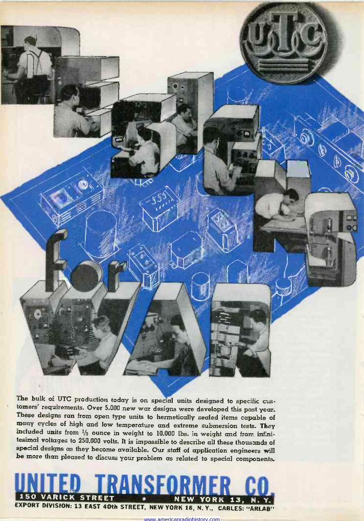
The bulk of UTC production today is on special units designed to specific cus- tomers' requirements. Over 5,000 new war designs were developed this past year. These designs ran from open type units to hermetically sealed items capable of many cycles of high and low temperature and extreme submersion tests. They included units from 1/3 ounce in weight to 10,000 lbs. in weight and frorr.. infini- tesimal voltages to 250,000 volts. It is impossible to describe all these thousands of special designs as they become available. Our staff of application engineers will be more than pleased to discuss your problem as related to special components.
I 81
i NEW YORK 13, N. Y. EXPORT DIVISION: 13 EAST 40th STREET, NEW YORK 16, N. Y., CABLES: "ARLAB"
www.americanradiohistory.com
ELECTRONIC INDUSTRIES
O. H. CALDWELL, EDITOR * M. CLEMENTS, PUBLISHER * 480 LEXINGTON AVE., NEW YORK (17), N. Y.
Better Post -War Production Design Returning soldiers, used to handling high -quality
radio and other equipment, are going to be critical of civilian "junk" when they see it. And the rest of the public-these soldiers' friends and relatives-are bound to be quite impressed by such comments. All kinds of radio -electronic apparatus will therefore have to be better designed, better built, better equipped, to get and hold respect.
Such apparatus will, of course, last longer. It will require less servicing. Resistors with a 200 per cent safety factor don't let go like those working "on the margin."
All this must mean higher original cost and higher retail price. But industry and the public will have learned that the answer to "why pay more?" is to get better, longer -lasting merchandise. Many products will be designed for maximum utility rather than max- imum profit or sales volume. The radio -electronic in- dustries, now working on rigid and precise military specifications, will have a considerable head start in the new type of post-war product design.
Inventiveness Can Be Overdone We must, of course, marvel at the engineering in-
genuity that issues from the industry's brain cells. But at the same time we are often prone to wonder just how much of this ingenuity represents any real advance in technique. Too often, design problems are solved in a way easiest for the designer, yet not as easy as might be for production. Frequently it is the "special" parts, newly designed to do a particular job, that run up costs, breed bottlenecks.
Again We Trim and Compress This issue reaches the reader with more -closely -set
and smaller type, and with page margins further trimmed-in an effort to furnish readers as much material as before, in the face of impending paper - tonnage reductions ordered by the Government. Though economizing on paper, we are determined not to cur- tail our editorial features or pages.
For while electronic manufacturing has increased 1200 per cent to 2000 per cent, the paper tonnage we are allowed to use per issue to serve this expand- ing field, is limited to a diminishing fraction of the paper we used in our first infant issues of 1942!
Radio departments of the Government urged the launching of a publication to render the unique war - radio service which we initiated. In fact the WPB's Radio Division endorsed our applications for increased paper allotments. But now other routine WPB regu- lations restrict the growing giant to the panties of his babyhood!
Why Can Others Double Their Size? Readers have asked us how other publications con-
tinue to increase their size and use of paper, while we cannot. In each such case it can be explained that the magazine so enlarged utilizes paper allot- ments of other publications owned by the same pub- lisher-magazines which have shrunk or have been discontinued. Unfortunately we have no such "lame ducks" to throw into our paper pool. And govern- ment regulations prevent us from acquiring such additional allotments by purchase.
That is why we now have to trim and slice and compress!
Next Month, another valuable Electronic Industries chart in colors - ELECTRONIC WELDING
Our chart supplement for November will give
a resumé of the advances in welding processes
that have been made possible by the applica- tion of the precise control of electronic devices.
The numerous fields of welding, the varia-
tions in the equipment and method to take care
of material, type of junction and size of pieces,
and such matters as the power availability, are all described and diagrammed in terms of physical
equipment requirements, circuits, operating data.
ELECTRONIC INDUSTRIES October, 1943 61
www.americanradiohistory.com
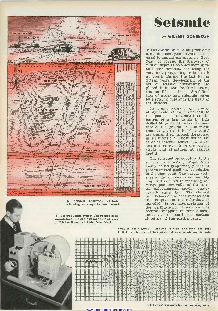
/NOT WLNT.
I RECORDING TRUC .
NMKv011 - 4ROD
MAN -..^. -.._ -q,.-. :.-t
-71r. i>...'mY" ,.y -.,e..._ c. Ret-
tiG di- +!rÿ=REFRACTION WAVES ,f / /%
...: _-_ ì _---_.:/ .-_-_-_-.7-_- - _ - ̀-1-_.._-__- - - -_ / / l -`Y -/- - - f -Z - . -- --f't`_ - - ! -- %-_ --.-1__ x__ -t- =_ I. r------------=----1 _ rl------------7--_--------5--__- -_ 1 c-. ----1-2--------7--2-----------,4-,_ --- ` i ___----_ _- = _'-= 1__ __
IRSTREFLEC7ION _---_-- _ -- -y _ _ == =í-r " = _________-___4-__ -__- __-_.,_-t - h_ _S.M-A-I_F--
i,,----_-__%_-.7\__:-._-__-----1--7- _"1"--- /t,' -`_-. i_-c.-:s - -
=- ----- . -T------,_"7---..,--__7:-:.- / _E - -_ _ ì-=,
_f-r_ _-_.3.-._._ / - I __-... ----- ___
- _--- ----t- --_,----_ 1..T.;_ = t >_: --r FIRST REFLECTING BED r BmaIERIMIBmaz arwEIRimRwmwiNiSiimE
_ - --i_=r__ `v -i-= - - F - - -t- _ __ -` f--' _--- - e:- - -- T-- --4- ---¡1/4-- . T _-_ r - - -_ --t--r si-=- -_z------"-_._ _ 4_7__,+,._-3,ì--- -4- _SECOND REFLECTION - - - -' - 3- rr -+--- - __L.- -- - --_-------IF =--_= -- - ----_-- - ._-_ 7-_- ______-1----- :I..=-
_ -- -- r- -- .- - -_ - - - - _ ..____% __f_ _-i SECONDREFLECTINGBED = ¡ - j L.r- 1- - - - - - . . . L L- 1 T
- , -, 1 1 L 1 1 ®C_A.Ni1LAN0 1 I l I 1 ¡ L i I 7 -L
1 1
JJJJ cjet lip
41/4 Seismic reflection technic,
showing wave -paths and record
4- Reproducing reflections recorded as sound -on -film, with Sonograph Analyzer nt Rieber Research Lab., New York
Seismic by GILBERT SONBERGH
Discoveries of new oil -producing areas in recent years have not been equal to annual consumption. Each year, of course, the discovery of new oil deposits becomes more diffi- cult. The necessity for using the very best prospecting technique is apparent. During the last ten or fifteen years, development of the art of seismic prospecting has placed it in the forefront among the possible methods. Amplifica- tion of audio and subsonic waves by electronic means is the heart of the method.
In seismic prospecting, a charge of dynamite of from one-half to ten pounds is detonated at the bottom of a four to six in. hole drilled 50 to 750 ft. below the sur- face of the ground. Elastic waves emanating from this "shot point" are transmitted through the ground in all directions. Those which are of chief interest travel downward, and are reflected from sub -surface strata and structures at various depths.
The reflected waves return to the surface to actuate pickups, com- monly called geophones, placed at predetermined positions in relation to the shot point. The output volt- ages of the geophones are suitably amplified and fed to recording os- cillographs, generally of the mir- ror - galvanometer, moving photo- graphic paper type. The elapsed time between the shot instant and the reception of the reflections is recorded. Proper interpretation of the oscillographic traces enables accurate mapping, in three dimen- sions, of the local sub - surface structure of the earth's crust.
Sample seismogram. Ground motion recorded for two 1000 -ft each side of two -pound dynamite charge in hole
ELECTRONIC INDUSTRIES October, 1943
www.americanradiohistory.com
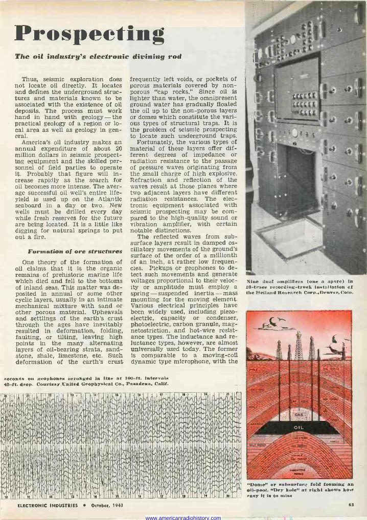
Prospecting The oil industry's electronic divining rod
Thus, seismic exploration does not locate oil directly. It locates and defines the underground struc- tures and materials known to be associated with the existence of oil deposits. The process must work hand in hand with geology - the practical geology of a region or lo- cal area as well as geology in gen- eral.
America's oil industry makes an annual expenditure of about 20 million dollars in seismic prospect- ing equipment and the skilled per- sonnel of field parties to operate it. Probably that figure will in- crease rapidly as the search for oil becomes more intense. The aver- age successful oil well's entire life - yield is used up on the Atlantic seaboard in a day or two. New wells must be drilled every day while fresh reserves for the future are being located. It is a little like digging for natural springs to put out a fire.
Formation of ore structures One theory of the formation of
oil claims that it is the organic remains of prehistoric marine life which died and fell to the bottoms of inland seas. This matter was de- posited in annual or some other cyclic layers, usually in an intimate mechanical mixture with sand or other porous material. Upheavals and settlings of the earth's crust through the ages have inevitably resulted in deformation, folding, faulting, or tilting, leaving high points in the many alternating layers of oil-bearing strata, sand- stone, shale, limestone, etc. Such deformation of the earth's crust
frequently left voids, or pockets of porous materials covered by non- porous "cap rocks." Since oil is lighter than water, the omnipresent ground water has gradually floated the oil up to the non -porous layers or domes which constitute the vari- ous types of structural traps. It is the problem of seismic prospecting to locate such underground traps.
Fortunately, the various types of material of these layers offer dif- ferent degrees of impedance or radiation resistance to the passage of pressure waves originating from the small charge of high explosive. Refraction and reflection of the waves result at those planes where two adjacent layers have different radiation resistances. The elec- tronic equipment associated with seismic prospecting may be com- pared to the high -quality sound or vibration amplifier, with certain notable distinctions.
The reflected waves from sub- surface layers result in damped os- cillatory movements of the ground's surface of the order of a millionth of an inch, at rather low frequen- cies. Pickups or geophones to de- tect such movements and generate voltages proportional to their veloc- ity or amplitude must employ a spring - suspended inertia - mass mounting for the moving element. Various electrical principles have been widely used, including piezo- electric, capacity or condenser, photoelectric, carbon granule, mag- netostriction, and hot-wire resist- ance types. The inductance and re- luctance types, however, are almost universally used today. The former is comparable to a moving -coil dynamic type microphone, with the
seconds on geophones arranged in line at 100 -ft. intervals 45 -ft. deep Courtesy United Geophysical Co., Pasadena, Calif.
Nine dual amplifiers lone a :spare) in 16-trnee recording -truck installation of the Helfand Research Corp.,. Denver, Colo.
"Dome" or subsurface fold forming an oll -pool., "Dry hole" at right shows how easy it is to miss
ELECTRONIC INDUSTRIES October, 1943 63
www.americanradiohistory.com
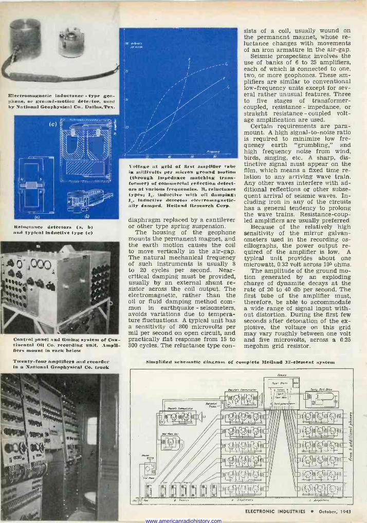
Electromagnetic inductance - type geo- phone, or ground -motion detector, used by National Geophysical Co.. Dallas.Tes.
Reluctance detectors (a, b and typical inductive type (e)
Control panel and timing system of Con- tinental Oil Co. recording unit. Ampli- fiers mount in rack below
Twenty-four amplifiers and recorder in a National Geophysical Co. truck
Voltage at grid of first amplifier tube in mi:livolts per micron ground tion (through impedance matching trans- former) of commercial reflection detect- ors nt various frequencies. R, reluctance types; 10, inductive with oil damping; Ie, inductive detector electromagnetic- ally damped. Heiland Research Corp.
diaphragm replaced by a cantilever or other type spring suspension.
The housing of the geophone mounts the permanent magnet, and the earth motion causes the coil to move vertically in the air -gap. The natural mechanical frequency of such instruments is usually 8 to 20 cycles per second. Near - critical damping must be provided, usually by an external shunt re- sistor across the coil output. The electromagnetic, rather than the oil or fluid damping method com- mon in earthquake - seisometers, avoids variations due to tempera- ture fluctuations. A typical unit has a sensitivity of 800 microvolts per mil per second on open circuit, and practically flat response from 15 to 300 cycles. The reluctance type con-
sists of a coil, usually wound on the permanent magnet, whose re- luctance changes with movements of an iron armature in the air -gap.
Seismic prospecting involves the use of banks of 6 to 25 amplifiers, each of which is connected to one, two, or more geophones. These am- plifiers are similar to conventional low -frequency units except for sev- eral rather unusual features. Three to five stages of transformer - coupled, resistance - impedance, or straight resistance - coupled volt- age amplification are used.
Certain requirements are para- mount. A high signal-to-noise ratio is required to minimize low fre- quency earth "grumbling," and high frequency noise from wind, birds, singing, etc. A sharp, dis- tinctive signal must appear on the film, which means a fixed time re- lation to any arriving wave train. Any other waves interfere with*ad- ditional reflections or other subse- quent arrival of seismic waves. In- cluding iron in any of the circuits has a general tendency to prolong the wave trains. Resistance -coup- led amplifiers are usually preferred.
Because of the relatively high sensitivity of the mirror galvan- ometers used in the recording os- cillographs, the power output re- quired of the amplifier is low. A typical unit provides about one microwatt, 0.32 volt across 105 ohms.
The amplitude of the ground mo- tion generated by an exploding charge of dynamite decays at the rate of 20 to 40 db per second. The first tube of the amplifier must, therefore, be able to accommodate a wide range of signal input with- out distortion. During the first few seconds after detonation of the ex- plosive, the voltage on this grid may vary roughly between one volt and five microvolts, across a 0.25 megohm grid resistor.
Simplified schematic diagraue of complete Heiland 12 -element system
Ca rra
nw 6 Per I AmP/i/iere
ELECTRONIC INDUSTRIES October, 1943
www.americanradiohistory.com
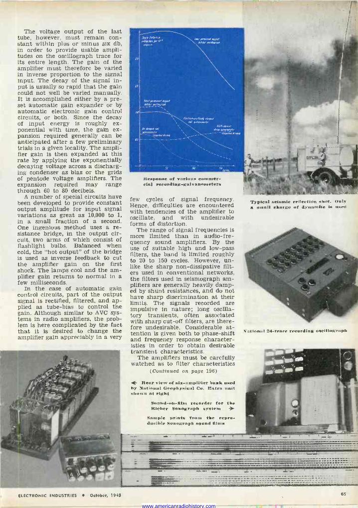
The voltage output of the last tube, however, must remain con- stant within plus or minus six db, in order to provide usable ampli- tudes on the oscillograph trace for its entire length. The gain of the amplifier must therefore be varied in inverse proportion to the signal input. The decay of the signal in- put is usually so rapid that the gain could not well be varied manually. It is accomplished either by a pre- set automatic gain expander or by automatic electronic gain control circuits, or both. Since the decay of input energy is roughly ex- ponential with time, the gain ex- pansion required generally can be anticipated after a few preliminary trials in a given locality. The ampli- fier gain is then expanded at this rate by applying the exponentially decaying voltage across a discharg- ing condenser as bias or the grids of pentode voltage amplifiers. The expansion required may range through 60 to 80 decibels.
A number of special circuits have been developed to provide constant output amplitude for input signal variations as great as 10,000 to 1, in a small fraction of a second. One ingenious method uses a re- sistance bridge, in the output cir- cuit, two arms of which consist of flashlight bulbs. Balanced when cold, the "hot output" of the bridge is used as inverse feedback to cut the amplifier gain on the first shock. The lamps cool and the am- plifier gain returns to normal in a few milliseconds.
In the case of automatic gain control circuits, part of the output signal is rectified, filtered, and ap- plied as tube -bias to control the gain. Although similar to AVC sys- tems in radio amplifiers, the prob- lem is here complicated by the fact that it is desired to change the amplifier gain appreciably in a very
PD
13
,D
Stole Dd/rrG.a \[anp p,rmanrn/metre/ endangers per ID'd /i/ar axi//opnpA ®err, ,
MAa,,prrmanml mapo,/ d/bm otrmpv,aM
. Da dampd rod
ei rnanrapneiaa/y du ord rad po/venane/er
_,warpaa/ .
Df -
_, _-_
Mn// ,bmrn/ ,ám, p/.anenea, - - -rwayx Dee ph J
Response of various commer- cial recording -galvanometers
few cycles of signal frequency. Hence, difficulties are encountered with tendencies of the amplifier to oscillate, and with undesirable forms of distortion.
The range of signal frequencies is more limited than in audio -fre- quency sound amplifiers. By the use of suitable high and low-pass filters, the band is limited roughly to 20 to 150 cycles. However, un- like the sharp non -dissipative filt- ers used in conventional networks, the filters used in seismograph am- plifiers are generally heavily damp- ed by shunt resistances, and do not have sharp discrimination at their limits. The signals recorded are impulsive in nature; long oscilla- tory transients, often associated with sharp cut-off filters, are there- fore undesirable. Considerable at- tention is given both to phase -shift and frequency response character- istics in order to obtain desirable transient characteristics.
The amplifiers must be carefully watched as to filter characteristics
(Continued on page 196)
4- Rear view of six -amplifier bank used by National Geophysical Co. Extra unit shown at right
Sound -on -film recorder for the Risher Sonograph system
Sample prints from the repro- ducible Sonograph sound films
Typical seismic reflection shot. Only it small charge of dynamite is used
National 24 -trace recording oscillograph
ELECTRONIC INDUSTRIES October, 1943 6
www.americanradiohistory.com
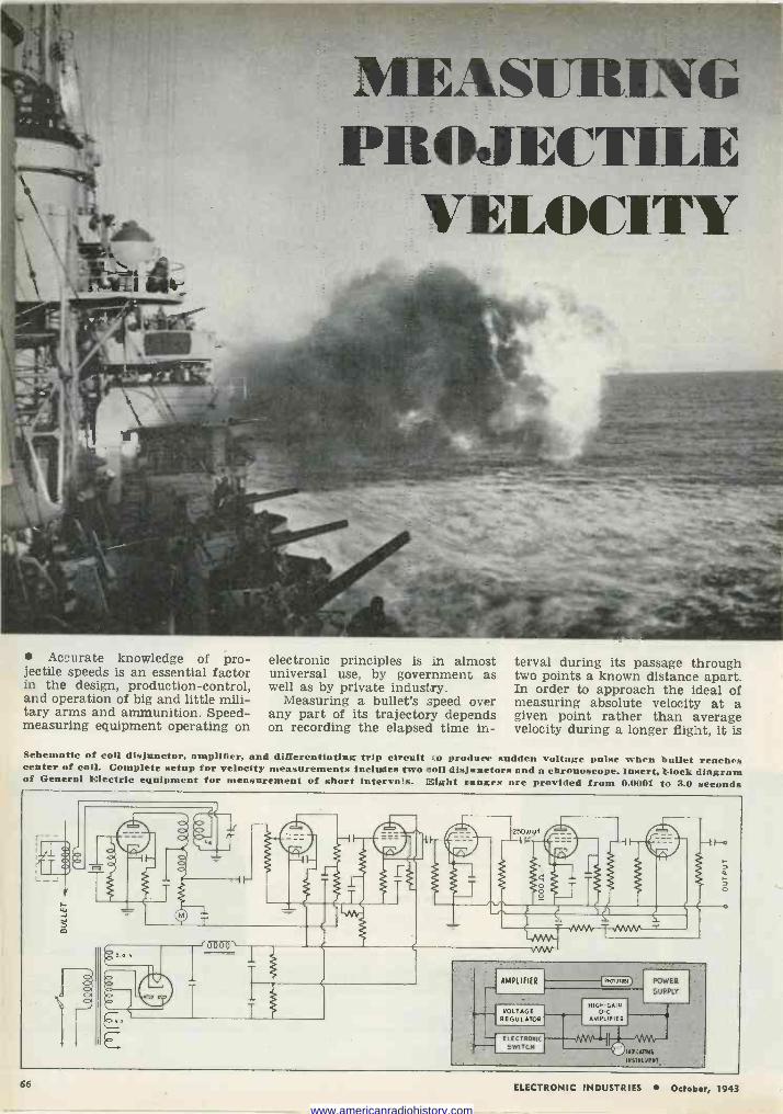
MEASURING t'ilOJECTILE
VELOCITY
Accurate knowledge of pro- jectile speeds is an essential factor in the design, production -control, and operation of big and little mili- tary arms and ammunition. Speed - measuring equipment operating on
electronic principles is in almost universal use, by government as well as by private industry.
Measuring a bullet's speed over any part of its trajectory depends on recording the elapsed time in-
terval during its passage through two points a known distance apart. In order to approach the ideal of measuring absolute velocity at a given point rather than average velocity during a longer flight, it is
Schematic of coil disjunctor, amplifier, and differentiating trip circuit to produce sudden Voltage pulse when bullet reaches center of coil. Complete setup for velocity measurements includes two coil disjanetors and a chronoscope. Insert, block diagram of General Electric equipment for measurement of short intervals. Eight ranges are provided from 0.0001 to 3.0 seconds
t 2501uf r Km.
E
á
ó
AMPLIFIER {'llClplUl
VOLTAGE REGULATOR
ELECTRONIC
SWITCH
HIGH GAIN O C
AMPLIFIER
POWER
SUPPLY
---VVVV"Li INOICV1144
INSTRUMENT
66 ELECTRONIC INDUSTRIES October, 1943
www.americanradiohistory.com
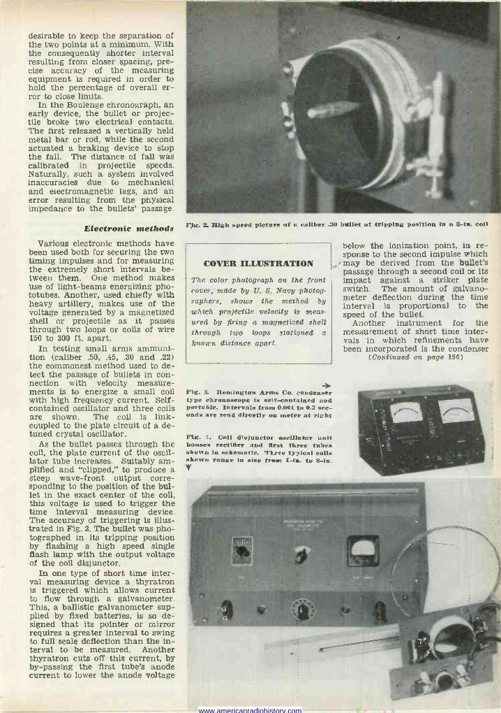
desirable to keep the separation of the two points at a minimum. With the consequently shorter interval resulting from closer spacing, pre- cise accuracy of the measuring equipment is required in order to hold the percentage of overall er- ror to close limits.
In the Boulenge chronograph, an early device, the bullet or projec- tile broke two electrical contacts. The first released a vertically held metal bar or rod, while the second actuated a braking device to stop the fall. The distance of fall was calibrated in projectile speeds. Naturally, such a system involved inaccuracies due to mechanical and electromagnetic lags, and an error resulting from the physical impedance to the bullets' passage.
Electronic methods Various electronic methods have
been used both for securing the two timing impulses and for measuring the extremely short intervals be- tween them. One method makes use of light -beams energizing pho- totubes. Another, used chiefly with heavy artillery, makes use of the voltage generated by a magnetized shell or projectile as it passes through two loops or coils of wire 150 to 300 ft. apart.
In testing small arms ammuni- tion (caliber .50, .45, .30 and .22) the commonest method used to de- tect the passage of bullets in con- nection with velocity measure- ments is to energize a small coil with high frequency current. Self- contained oscillator and three coils are shown. The coil is link - coupled to the plate circuit of a de - tuned crystal oscillator.
As the bullet passes through the coil, the plate current of the oscil- lator tube increases. Suitably am- plified and "clipped," to produce a steep wave -front output corre- sponding to the position of the bul- let in the exact center of the coil, this voltage is used to trigger the time interval measuring device. The accuracy of triggering is illus- trated in Fig. 2. The bullet was pho- tographed in its tripping position by flashing a high speed single flash lamp With the output voltage of the coil disjunctor.
In one type of short time inter- val measuring device a thyratron is triggered which allows current to flow through a galvanometer. This, a ballistic galvanometer sup- plied by fixed batteries, is so de- signed that its pointer or mirror requires a greater interval to swing to full scale deflection than the in- terval to be measured. Another thyratron cuts off this current, by by-passing the first tube's anode current to lower the anode voltage
below the ionization point, in re- sponse to the second impulse which may be derived from the bullet's passage through a second coil or its impact against a striker plate switch. The amount of galvano- meter deflection during the time interval is proportional to the speed of the bullet.
Another instrument for the measurement of short time inter- vals in which refinements have been incorporated is the condenser
(Continued on page 196)
Fig. 2. High speed picture of a caliber .30 bullet at tripping position in a 3 -in. coil
COVER ILLUSTRATION
The color photograph on the front cover, made by U. S. Navy photog- raphers, shows the method by which projectile velocity is meas- ured by firing a magnetized shell through two loops stationed a known distance apart.
Fig. 3. Remington Arms Co. condenser type ehronoscope is self-contained and portable. Intervals from 0.001 to 0.2 sec- onds are read directly on meter at right
Fig. 1. Coil disjunctor oscillator unit houses rectifier and first three tubes shown in schematic. Three typical coils shown range in size from 1 -in. to 8 -in. V
www.americanradiohistory.com
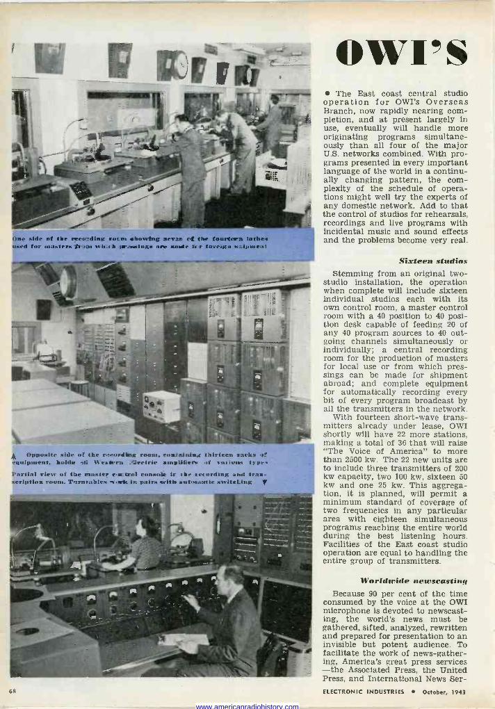
One side of the recording socm showing seven of the fourteen lathe; used for masters fr rat srlr.Ji ir2easinfçs net nude fir foreign .+cipone:it
Opposite side ut the r. -ordiog room, eontai:tin:; thirteen sacks of equipment, holds çü %extern _eeetrie <tmpllfiers. rf v:wlol» t)'pes Cn rt ial view of the twister eoetrol console it the ret ording and traa- seription room. Tnrnrableß -t-r1& in pairs s; ith sutoa,uttic savitet..
owl's The East coast central studio
operation for OWI's Overseas Branch, now rapidly nearing com- pletion, and at present largely in use, eventually will handle more originating programs simultane- ously than all four of the major U.S. networks combined. With pro- grams presented in every important language of the world in a continu- ally changing pattern, the com- plexity of the schedule of opera- tions might well try the experts of any domestic network. Add to that the control of studios for rehearsals, recordings and live programs with incidental music and sound effects and the problems become very real.
Sixteen studios Stemming from an original two -
studio installation, the operation when complete will include sixteen individual studios each with its own control room, a master control room with a 40 position to 40 posi- tion desk capable of feeding 20 of any 40 program sources to 40 out- going channels simultaneously or individually; a central recording room for the production of masters for local use or from which pres- sings can be made for shipment abroad; and complete equipment for automatically recording every bit of every program broadcast by all the transmitters in the network.
With fourteen short-wave trans- mitters already under lease, OWI shortly will have 22 more stations, making a total of 36 that will raise "The Voice of America" to more than 2500 kw. The 22 new units are to include three transmitters of 200 kw capacity, two 100 kw, sixteen 50 kw and one 25 kw. This aggrega- tion, it is planned, will permit a minimum standard of coverage of two frequencies in any particular area with eighteen simultaneous programs reaching the entire world during the best listening hours. Facilities of the East coast studio operation are equal to handling the entire group of transmitters.
Worldwide newscasting Because 90 per cent of the time
consumed by the voice at the OWI microphone is devoted to newscast- ing, the world's news must be gathered, sifted, analyzed, rewritten and prepared for presentation to an invisible but potent audience. To facilitate the work of news -gather- ing, America's great press services -the Associated Press, the United Press, and International News Ser -
68 ELECTRONIC INDUSTRIES October, 1943
www.americanradiohistory.com
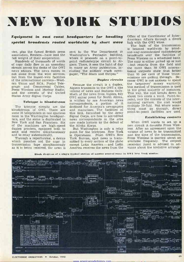
NEW YORK STUDIOS Equipment in east coast special broadcasts routed
vice, plus the famed British press association, Reuters-have lent the full weight of their cooperation.
Hundreds of thousands of words of copy daily flow in an unending stream across the desks of the OWI news editors. The news comes in not alone from the wire services, but from the leased -wire facilities of the international carriers-West- ern Union and RCA; Postal Tele- graph and Commercial Cables; Press Wireless and Mackay Radio; and the circuits of the United States Army Signal Corps.
Teletype is bloodstream The teletype circuits are the
bloodstream of OWI. There are some 25 teleprinters in one spacious room in the Washington headquar- ters, and the scene is duplicated in New York and San Francisco. Six of the machines are high-speed duplex printers, equipped both to send and receive simultaneously and to relay automatically.
Through a reperforator, a device which punches out the copy in transmission tape simultaneously as it is being received, the news is
headquarters for handling worldwide by short wave
sent to the War Department in Washington's Pentagon building, where it proceeds on a point-to- point radioteletype circuit to Al- giers. There, it sees the light of day in many an Army publication, in- cluding the soldiers' crack news- paper, "The Stars and Stripes."
Duplex circuits Because the circuit is a duplex,
Algiers transmits to the OWI a like volume of news and features daily. Much of the news from Algiers, key OWI signal point for North Africa, is written by ace American news correspondents, a portion of it destined for America's newspapers and magazines. The facilities of this link, furnished by the Army Signal Corps, are free to accredited news correspondents in the area now made historic by the defeat of the Afrika Korps.
But Washington is only a relay point for the teletypes. New York is Operations. From OWI's New York Bureau, spot news is trans- mitted to every section of the globe except Latin America - and Latin America receives the news from the
Office of the Coordinator of Inter - American Affairs through a direct link with the OWI wires.
The bulk of the transmission is beamed worldwide by blind - one -way -uncontrolled radioteletype broadcasts over the facilities of Press Wireless on a scheduled basis. The copy is either picked up or lost -but reports from the field and the more than 30 OWI interna- tional outposts show that better than 95 per cent of these trans- missions are getting through. Be- cause OWI is not anxious to spend the taxpayers' money wantonly, this method of transmission is used in the great majority of instances. This way, the cost breaks down to about two cents a word. Point-to- point, over the circuits of the inter- national carriers, the cost would multiply 20 -fold. But where some- thing must go through, direct point-to-point facilities are used.
Establishing contacts When OWI wants to set up a
new circuit it consults Press Wire- less. After an agreement upon the volume of news to be transmitted and the time of the transmission, Press Wireless is queried about an available frequency. The outpost receiving point is advised in ad- vance about the tentative arrange -
Block diagram of n single typical section of master control room in OR'I New York studios
FLPRE_ L2)-,ÁEaOB
TALI( BACK TO O TRANS. 1
TRANSCRIP1O ,_f 1 MI%ER
¡FLA,TMB MIC
TALK BACK TO
,/ A117ER
f' WE1126A L'..Í
LIMITER
WE :1266
TRANS 2. TRANSCRIPTION
2tÑIMER o -V 1J
FROM STUDIO o-. I.
I:EI'.E,VE LINE 0--- I.
P5 RI
400
60011 - 60011 PAD LOSS 6 V U.
OA-IBOA PAD LOSS {ZV.U.____ 05A-20MA PAD LOSS 6 V U.
600A-I5O11, PAD LOSS iB M U 600.0 ' 6006L-6000 SPLIT PAO LUGS 6V17.1
B. FLASH to TRANSCRIPTION RM. RELAr ASH TSMU TA,WSCRIPTION RH. ÑEZAY
M5Ñ116q TRANSFER RELAYS FLASH HARiREL RELAYS
LL, LEVELS GIVEN IN V U. IMw REFERENCE Al LTIRCV ITS BALANCED TO Fi 4O. EA, ÏS SHOWN
w.l
REG LI
MD 830
T'-'1
'I v n.4+.[6f,
«Y'
9 ''-. I.
SECONDARY LINE AMP RCA 830
SECONDARY
CHANNEL
RELAYS
STUDIO OR 1E LINE E'
SELECT z) RELAYS ro
,t0;0,2e.+.e01 L.-
LINE REVERSAI,
RELAY
_T RECEIVE UNE OUT.
POSITpN,-i ¡..,w :nr i50uTtCn .
RELAYSSELECT
-lv7AMPe5% _t i
r --------- I
I
i1 ' ISOLATpA
LINE MON SELECT SWITCH N2
8 -0 SPARE
40.0
B PRIME O TAANSNIT TINC
LINE
i---0 MEMOVO%
46 TRANSCRIPTIC'R j LT dMONtTOA LINE
AT '', 46 DIAL MONITOR 1' EED(STROGER'
SECTION
1_ ROTART = 1 -0aUTOMO. SWITCH ñ. j TO STVTICCIOS
-6 STUDIO FEED' ------` RECORDING ß.
_-6 FE
DIAL ED FNOM MOTU LOK
STUDIO +6-OAAL
EMOD FRNITOM FEOR LINE
LINE CORDING
FEED TC RE
DATTERY
AVD10
O
O
SELECTOR DIAL
STROGER, NDA
j7 TEST !rU MCNiTGA
ELECTRONIC INDUSTRIES October, 1943 50.
www.americanradiohistory.com
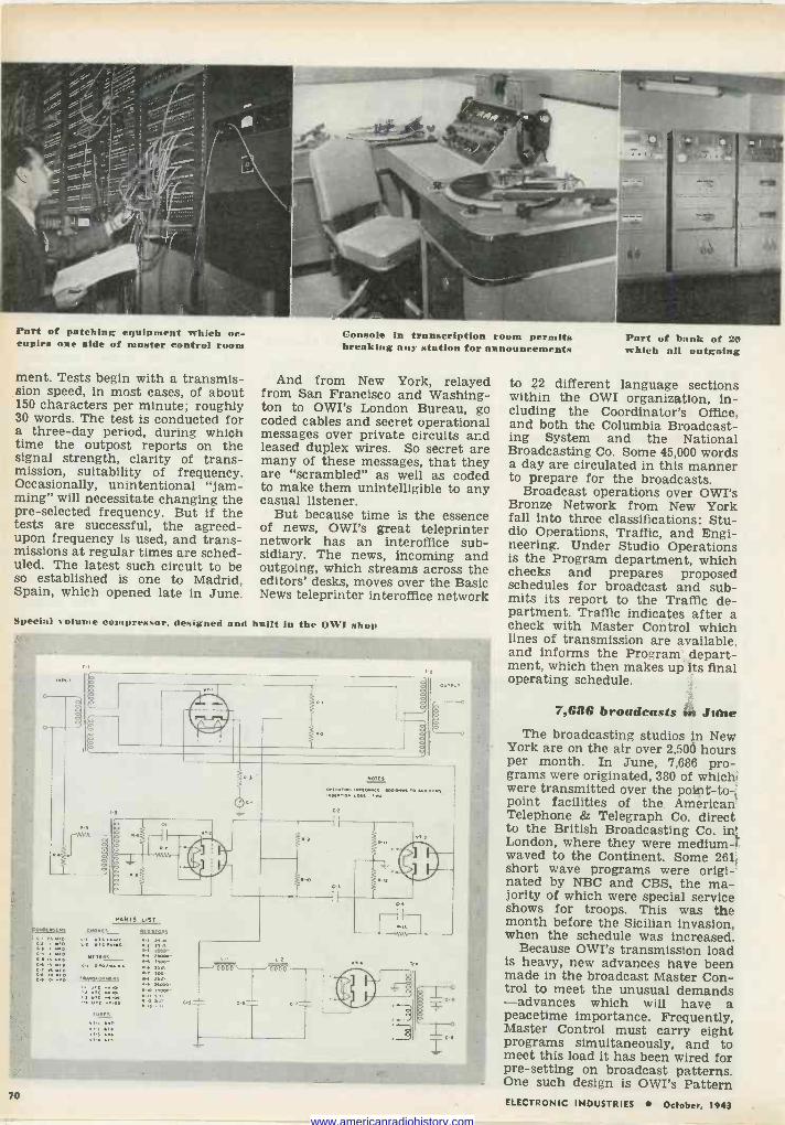
Part of patching equipment which oc- cupies one side of master control room
ment. Tests begin with a transmis- sion speed, in most cases, of about 150 characters per minute; roughly 30 words. The test is conducted for a three-day period, during which time the outpost reports on the signal strength, clarity of trans- mission, suitability of frequency. Occasionally, unintentional "jam- ming" will necessitate changing the pre -selected frequency. But if the tests are successful, the agreed - upon frequency is used, and trans- missions at regular times are sched- uled. The latest such circuit to be so established is one to Madrid, Spain, which opened late in June.
Console in transcription room permits breaking any station for announcements
And from New York, relayed from San Francisco and Washing- ton to OWI's London Bureau, go coded cables and secret operational messages over private circuits and leased duplex wires. So secret are many of these messages, that they are "scrambled" as well as coded to make them unintelligible to any casual listener.
But because time is the essence of news, OWI's great teleprinter network has an interoffice sub- sidiary. The news, incoming and outgoing, which streams across the editors' desks, moves over the Basic News teleprinter interoffice network
Special volume compressor, designed and built in the OWI shop
0 On
o
PARTS LIST
APPALS AESKi0n5
`o ó2 ..0c 111e4wSlOP..495
1 traES
Oter
te
e 21000-
70
Part of bank of 20 which all outgoing
to 22 different language sections within the OWI organization, in- cluding the Coordinator's Office, and both the Columbia Broadcast- ing System and the National Broadcasting Co. Some 45,000 words a day are circulated in this manner to prepare for the broadcasts.
Broadcast operations over OWI's Bronze Network from New York fall into three classifications: Stu- dio Operations, Traffic, and Engi- neering. Under Studio Operations is the Program department, which checks and prepares proposed schedules for broadcast and sub- mits its report to the Traffic de- partment. Traffic indicates after a check with Master Control which lines of transmission are available, and informs the Program depart- ment, which then makes up its final operating schedule.
7,686 broadcasts in June The broadcasting studios In New
York are on the air over 2,50O hours per month. In June, 7,686 pro- grams were originated, 380 of which- were transmitted over the point -to -4 point facilities of the American Telephone & Telegraph Co. direct to the British Broadcasting Co. in: London, where they were medium -i waved to the Continent. Some 261, short wave programs were origi- nated by NBC and CBS. the ma- jority of which were special service shows for troops. This was the month before the Sicilian invasion, when the schedule was increased.
Because OWI's transmission load is heavy, new advances have been made in the broadcast Master Con- trol to meet the unusual demands -advances which will have a peacetime importance. Frequently, Master Control must carry eight programs simultaneously, and to meet this load it has been wired for pre-setting on broadcast patterns. One such design is OWI's Pattern ELECTRONIC INDUSTRIES October, 1943
www.americanradiohistory.com
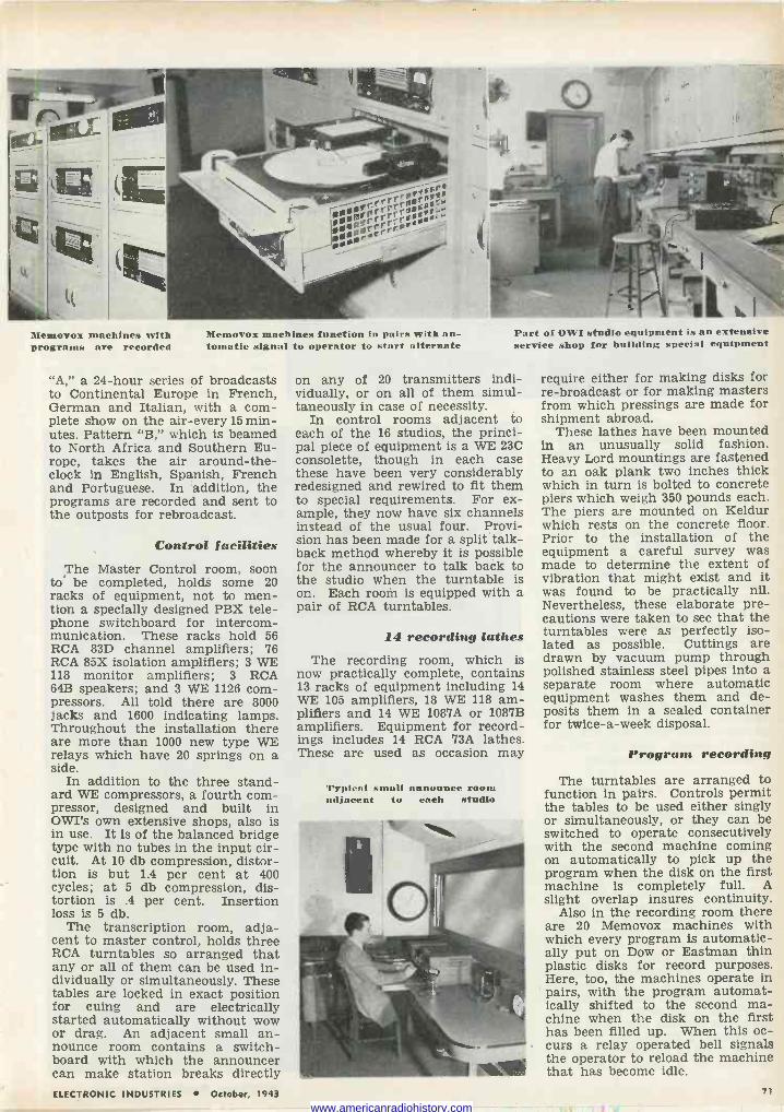
Memovox machines with programs are recorded
Memovox machines function in pairs with au- tomatic signal to operator to start alternate
"A," a 24 -hour series of broadcasts to Continental Europe in French, German and Italian, with a com- plete show on the air -every 15 min- utes. Pattern "B," which is beamed to North Africa and Southern Eu- rope, takes the air around -the - clock in English, Spanish, French and Portuguese. In addition, the programs are recorded and sent to the outposts for rebroadcast.
Control facilities The Master Control room, soon
to be completed, holds some 20 racks of equipment, not to men- tion a specially designed PBX tele- phone switchboard for intercom- munication. These racks hold 56 RCA 83D channel amplifiers; 76 RCA 85X isolation amplifiers; 3 WE 118 monitor amplifiers; 3 RCA 64B speakers; and 3 WE 1126 com- pressors. All told there are 8000 jacks and 1600 indicating lamps. Throughout the installation there are more than 1000 new type WE relays which have 20 springs on a side.
In addition to the three stand- ard WE compressors, a fourth com- pressor, designed and built in OWI's own extensive shops, also is in use. It is of the balanced bridge type with no tubes in the input cir- cuit. At 10 db compression, distor- tion is but 1.4 per cent at 400 cycles; at 5 db compression, dis- tortion is .4 per cent. Insertion loss is 5 db.
The transcription room, adja- cent to master control, holds three RCA turntables so arranged that any or all of them can be used in- dividually or simultaneously. These tables are locked in exact position for cuing and are electrically started automatically without wow or drag. An adjacent small an- nounce room contains a switch- board with which the announcer can make station breaks directly
Part of OW1 studio equipment is an extensive service shop for building special equipment
on any of 20 transmitters indi- vidually, or on all of them simul- taneously in case of necessity.
In control rooms adjacent to each of the 16 studios, the princi- pal piece of equipment is a WE 23C consolette, though in each case these have been very considerably redesigned and rewired to fit them to special requirements. For ex- ample, they now have six channels instead of the usual four. Provi- sion has been made for a split talk - back method whereby it is possible for the announcer to talk back to the studio when the turntable is on. Each room is equipped with a pair of RCA turntables.
14 recording lathes The recording room, which is
now practically complete, contains 13 racks of equipment including 14 WE 105 amplifiers, 18 WE 118 am- plifiers and 14 WE 1087A or 1087B amplifiers. Equipment for record- ings includes 14 RCA 73A lathes. These are used as occasion may
Typical small announce room adjacent to each studio
require either for making disks for re -broadcast or for making masters from which pressings are made for shipment abroad.
These lathes have been mounted in an unusually solid fashion. Heavy Lord mountings are fastened to an oak plank two inches thick which in turn is bolted to concrete piers which weigh 350 pounds each. The piers are mounted on Keldur which rests on the concrete floor. Prior to the installation of the equipment a careful survey was made to determine the extent of vibration that might exist and it was found to be practically nil. Nevertheless, these elaborate pre- cautions were taken to see that the turntables were as perfectly iso- lated as possible. Cuttings are drawn by vacuum pump through polished stainless steel pipes into a separate room where automatic equipment washes them and de- posits them in a sealed container for twice -a -week disposal.
Program recording
The turntables are arranged to function in pairs. Controls permit the tables to be used either singly or simultaneously, or they can be switched to operate consecutively with the second machine coming on automatically to pick up the program when the disk on the first machine is completely full. A slight overlap insures continuity.
Also in the recording room there are 20 Memovox machines with which every program is automatic- ally put on Dow or Eastman thin plastic disks for record purposes. Here, too, the machines operate in pairs, with the program automat- ically shifted to the second ma- chine when the disk on the first has been filled up. When this oc- curs a relay operated bell signals the operator to reload the machine that has become idle.
ELECTRONIC INDUSTRIES October, 1943 71
www.americanradiohistory.com
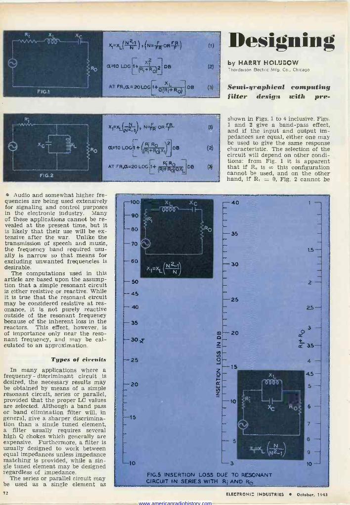
z t } X,1=XL(N -Kr i l t"7--OR-r/
1+(Ri+RO DB
AT FR,(X=20 LOG [1+ X L Q(RÌ+ROÌ
DB
(1)
(2)
(3)
x1'xiktzN t N- OR F'
Q=10LOG1+(Ri RXi)2
OB
Ro AT RA=20 LOG 1+(R+RaQXLIDB
(I)
Audio and somewhat higher fre- quencies are being used extensively for signaling and control purposes in the electronic industry. Many of these applications cannot be re- vealed at the present time, but it is likely that their use will be ex- tensive after the war. Unlike the transmission of speech and music, the frequency band required usu- ally is narrow so that means for excluding unwanted frequencies is desirable.
The computations used in this article are based upon the assump- tion that a simple resonant circuit is either resistive or reactive. While it is true that the resonant circuit may be considered resistive at res- onance, it is not purely reactive outside of the resonant frequency because of the inherent loss in the reactors. This effect, however, is of importance only near the reso- nant frequency, and may be cal- culated to an approximation.
Types of circuits In many applications where a
frequency - discriminant circuit is desired, the necessary results may be obtained by means of a simple resonant circuit, series or parallel, provided that the proper LC values are selected. Although a band pass or band elimination filter will, in general, give a sharper discrimina- tion than a single tuned element, a filter usually requires several high Q chokes which generally are expensive. Furthermore, a filter is usually designed to work between equal impedances unless impedance matching is provided, while a sin- gle tuned element may be designed regardless of impedance.
The series or parallel circuit may be used as a single element as
Designing by HARRY HOLUDOW Thordarson Electric Mfg. Co., Chicago
Semi -graphical computing filter design with pre -
shown in Figs. 1 to 4 inclusive. Figs. 1 and 2 give a band-pass effect, and if the input and output im- pedances are equal, either one may be used to give the same response characteristic. The selection of the circuit will depend on other condi- tions: from Fig. 1 it is apparent that if R. is 00 this configuration cannot be used, and on the other hand, if R, - 0, Fig. 2 cannot be
-100 XL X
14,, }---, - -90
.> - -
-80 RO
- -35 - - 70 0 _ -
- 1.5-
`60 /N2-11 -30 -
X17-9(1._( l - - 50 2 - - 45 - -25
--140_ 25
- 35 - 3 - c»-20 2 -30 x z¡ +
ac 3.5- ~ -2 5 (-- 4 ,.
c-15 ÓI-- r- - xL 4.5-
I.20 w - tN Z
-- -
5 - - r-10 1--J _ - XC R O 6 -I -15 1-
- - Q 7 --
-- 5 8 _.
- I
L 14Z-1 º -
--10 L- 3 10 -J
FIG.5 INSERTION LOSS DUE TO RESONANT GIRCU{T iN SERiES, WITH Ri AND,P.0
72 ELECTRONIIC INDUSTRIES October, 19;3
www.americanradiohistory.com
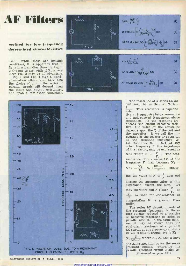
AF Filters
method for low frequency determined characteristics
used. While these are limiting conditions, it is apparent that if R, is much smaller than R0, Fig. 1
is the one to use, while if R. is very large Fig. 2 may be of advantage.
Fig. 3 and Fig. 4 give a band - elimination effect, and here also the choice of either the series or parallel circuit will depend upon the input and output resistances, and upon a few other conditions.
xl-x L(NN11 rl
OU --10 LOG t,+(+xl)
ATFR,a=20LOG lt(R
Dß
DB
(1)
í2)
(3)
Ri
FIG.4
x N =x L(N2_1%
( x? a ¡ =loloG,11+-2 DB
(I)
(2)
AT FR,a= 20 LOG I1+ Q' R DB (3)
. . .._... .....
-100 .,.ß. -.. ,-
..
40
E - -90
L - v
-80 .i.
Z
_35 ` _ -70
i - 1.5- ..._ 60 -30
(1-.:X' N -,
- 50 _
2
-45 _
-25 - 40 " 2.5 .-.
`35 CO
0 - 3 . 20
.._.. 30 ? - x O _+
O Ñ 3.5-
Cr 2-- 0- J -25 - 4 - Ó ---- 15 I= rt w-
- 4.5- -20 N_ 5 -- - Z _
- 10 >RI L i - `> RO > 6 ^ _ .>>
-15 ` _ - XC ; 7 -
- -
a 8 - _ - L N1 N á - -10 -3 10 -
``FIG.S INSERTION LOSS DUE -0 A RESONANT CIRCUIT IN PARALLEL WITH RO
The reactance of a series LC cir- cuit may be written as 27TfL - 1 This reactance is capacita- 27fc. tive at frequencies below resonance and inductive at frequencies above resonance. At the resonant fre- quency the circuit becomes resis- tive; the value of the resistance depends upon the Q of the coil and the capacitor. If we call the im- pedance of the reactor or capacitor at the resonant frequency XL (at resonance Xi, = X(;), at any other frequency F, the impedance of the reactor, may be expressed as NXr, where N = F . The total
F, reactance of the series LC at the frequency F then becomes X1 - NXi, - N1'= XI, (N2- ). Chang-
ing the value of N to lT
does not
change the absolute value of this expression, except the sign. We
may therefore call N either F or
F'- so that for convenience of F
computation N is greater than unity.
The series LC circuit, outside of the resonant frequency, is there- fore quickly reduced to a positive or negative reactance in series or parallel with R0. In the same man- ner it may be shown that the equivalent reactance of a parallel LC circuit at any frequency (outside of the resonant frequency) is X1
Xi. N2N where XI,, X1 and N have
the same meaning as for the series esonant circuit. Therefore the arallel resonant circuit is also re-
(Contisned on page 188)
ELECTRONIC INDUSTRIES October, 1943 73
www.americanradiohistory.com
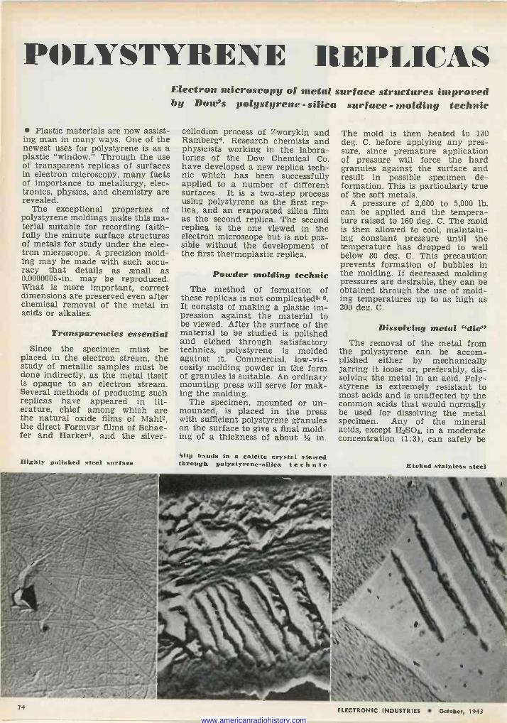
POLYSTYRENE t[EPLICAS
Plastic materials are now assist- ing man in many ways. One of the newest uses for polystyrene is as a plastic "window." Through the use of transparent replicas of surfaces in electron microscopy, many facts of importance to metallurgy, elec- tronics, physics, and chemistry are revealed.
The exceptional properties of polystyrene moldings make this ma- terial suitable for recording faith- fully the minute surface structures of metals for study under the elec- tron microscope. A precision mold- ing may be made with such accu- racy that details as small as 0.0000005 -in. may be reproduced. What is more important, correct dimensions are preserved even after chemical removal of the metal in acids or alkalies.
Transparencies essential Since the specimen must be
placed in the electron stream, the study of metallic samples must be done indirectly, as the metal itself is opaque to an electron stream. Several methods of producing such replicas have appeared in lit- erature, chief among which are the natural oxide films of Mahl2, the direct Formvar films of Schae- fer and Harker3, and the silver -
Highly polished steel surface
Electron microscopy of metal surface structures improved by Dow's polystyrene - silica surface - molding technic
collodion process of Zworykin and Ramberg4. Research chemists and physicists working in the labora- tories of the Dow Chemical Co. have developed a new replica tech- nic which has been successfully applied to a number of different surfaces. It is a two-step process using polystyrene as the first rep- lica, and an evaporated silica film as the second replica. The second replica is the one viewed in the electron microscope but is not pos- sible without the development of the first thermoplastic replica.
Powder molding technic The method of formation of
these replicas is not complicated5. 6 It consists of making a plastic im- pression against the material to be viewed. After the surface of the material to be studied is polished and etched through satisfactory technics, polystyrene is molded against it. Commercial, low -vis- cosity molding powder in the form of granules is suitable. An ordinary mounting press will serve for mak- ing the molding.
The specimen, mounted or un- mounted, is placed in the press with sufficient polystyrene granules on the surface to give a final mold- ing of a thickness of about in.
Slip bands in a calcite crystal viewed through polystyrene -silica technic
The mold is then heated to 130 deg. C. before applying any pres- sure, since premature application of pressure will force the hard granules against the surface and result in possible specimen de- formation. This is particularly true of the soft metals.
A pressure of 2,000 to 5,000 lb. can be applied and the tempera- ture raised to 160 deg. C. The mold is then allowed to cool, maintain- ing constant pressure until the temperature has dropped to well below 80 deg. C. This precaution prevents formation of bubbles in the molding. If decreased molding pressures are desirable, they can be obtained through the use of mold- ing temperatures up to as high as 200 deg. C.
Dissolving metal "die" The removal of the metal from
the polystyrene can be accom- plished either by mechanically jarring it loose or, preferably, dis- solving the metal in an acid. Poly- styrene is extremely resistant to most acids and is unaffected by the common acids that would normally be used for dissolving the metal specimen. Any of the mineral acids, except H2SO4, in a moderate concentration (1:3), can safely be
Etched stainless steel
74 ELECTRONIC INDUSTRIES October, 1943
www.americanradiohistory.com
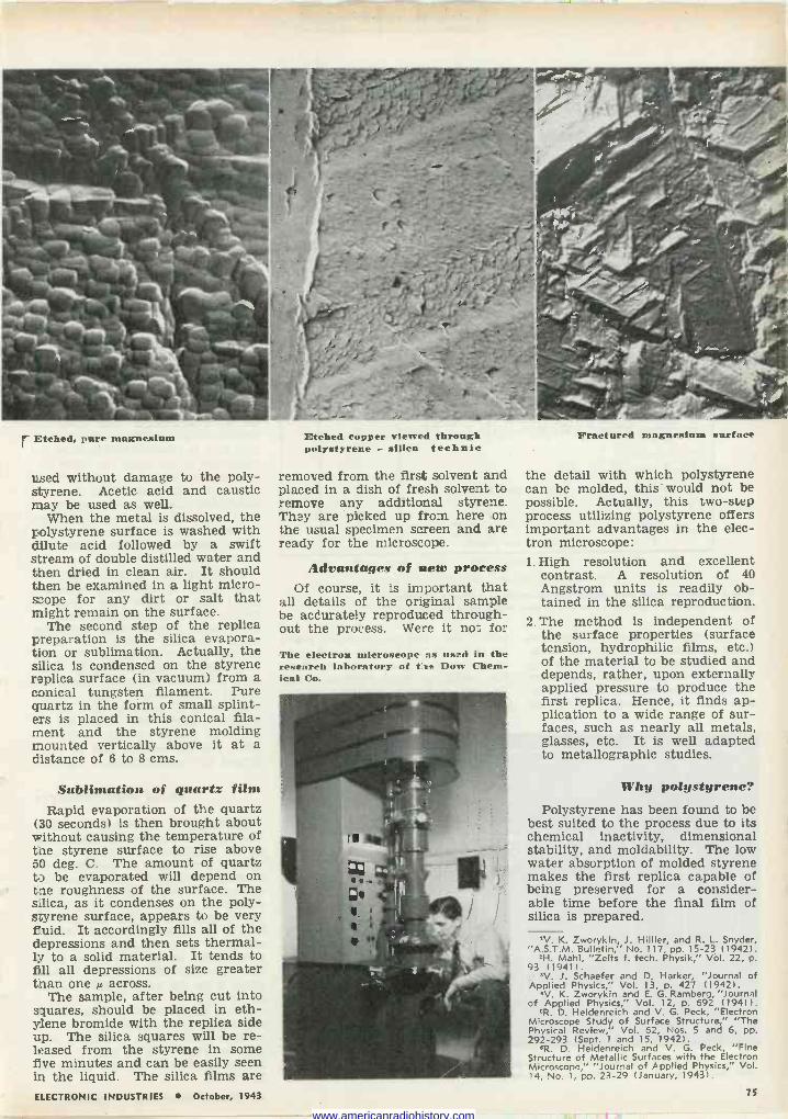
1 11
r Etched, pure magnesium
Lsed without damage to the poly- styrene. Acetic acid and caustic may be used as well.
When the metal is dissolved, the polystyrene surface is washed with dilute acid followed by a swift stream of double distilled water and then dried in clean air. It should then be examined in a light micro- scope for any dirt or salt that might remain on the surface.
The second step of the replica preparation is the silica evapora- tion or sublimation. Actually, the silica is condensed on the styrene replica surface (in vacuum) from a conical tungsten filament. Pure quartz in the form of small splint- ers is placed in this conical fila- ment and the styrene molding mounted vertically above it at a distance of 6 to 8 ems.
Sublimation of quartz film Rapid evaporation of the quartz
(30 seconds) is then brought about without causing the temperature of the styrene surface to rise above 50 deg. C. The amount of quartz to be evaporated will depend on the roughness of the surface. The silica, as it condenses on the poly- styrene surface, appears to be very f.uid. It accordingly fills all of the depressions and then sets thermal- ly to a solid material. It tends to fill all depressions of size greater than one r< across.
The sample, after being cut into squares, should be placed in eth- ylene bromide with the replica side up. The silica squares will be re- leased from the styrene in some eve minutes and can be easily seen in the liquid. The silica films are
Etched copper viewed through polystyrene - silica technic
removed from the first solvent and placed in a dish of fresh solvent to remove any additional styrene. They are picked up from here on the usual specimen screen and are ready for the microscope.
Advantages of nets process Of course, it is important that
all details of the original sample be accurately reproduced through- out the process. Were it not for
The electron microscope as used in the research laboratory of the Dow Chem- ical Co.
Fractured magnesium surface
the detail with which polystyrene can be molded, this would not be possible. Actually, this two-step process utilizing polystyrene offers important advantages in the elec- tron microscope: 1. High resolution and excellent
contrast. A resolution of 40 Angstrom units is readily ob- tained in the silica reproduction.
2. The method is independent of the surface properties (surface tension, hydrophilic films, etc.) of the material to be studied and depends, rather, upon externally applied pressure to produce the first replica. Hence, it finds ap- plication to a wide range of sur- faces, such as nearly all metals, glasses, etc. It is well adapted to metallographic studies.
Why polystyrene? Polystyrene has been found to be
best suited to the process due to Its chemical inactivity, dimensional stability, and moldability. The low water absorption of molded styrene makes the first replica capable of being preserved for a consider- able time before the final film of silica is prepared.
'V. K. Zworykin J. Hillier, and R. L. Snyder, "A.S.T.M. Bulletin!' No. 117, pp. 15-23 (1942).
'H. Mahl, "Zeits f. tech. Physik," Vol. 22, p. 93 (1941).
"V. J. Schaefer and D. Harker, "Journal of Applied Physics," Vol. 13, p. 427 (1942).
'V. K. Zworykin and E. G. Ramberg, "Journal of Applied Physics," Vol. 12, p. 692 (19411.
"R. D. Heidenreich and V. G. Peck, "Electron Microscope Study of Surface Structure," "The Physical Review," Vol. 62, Nos. 5 and 6, pp. 292-293 (Sept. 1 and 15, 1942).
'R. D. Heidenreich and V. G. Peck, "Fine Structure of Metallic Surfaces with the Electron Microscope," "Journal of Applied Physics," Vol. 14, No. 1, pp. 23-29 (January, 19431.
ELECTRONIC INDUSTRIES October, 1943
1 If
75
www.americanradiohistory.com
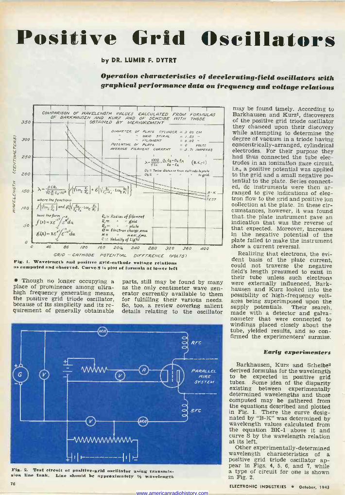
Positive Grid Oscillators
350
300
250
200
/50
/00
50
by DR. LUMIR F. DYTRT
Operation characteristics of decelerating -field oscillators with graphical performance data on frequency and voltage relations
I I I I I I ( I I
COMPARISON OF {NAVELENGTH VALUES CALCULATED FROM FORMULAS OF BARKHAUSEN AND KURZ AND OF SCHEIBE W/TH THOSE
OBTAINED BY MEASUREMENT
\\
D/AMETER OF PLATE CYL/NOER = 3 00 CM GR/O SP/RAG = /.23 '
" F/LAMENT POTENT/AL OF PLATE = O VOLTS AVERAGE F/LAMENT CURRENT = 3.7/ AMPERES
. .
1000 Ea -Da En
Ea Eu-Ex ,-1)
DA __ Twice dislmee from ca/h.,de lop/ale Do ., ragr;d.
- x= -72,1_`'E;08 dlf Ea .Loa ß'711 {/[3'7.(j..,-]+ LEGEA E R
1
where the functions lI f[ Lane ó 1
and g[,/E` .106E R 1
have the fo f (X)=xs: dodu x
(x)= xexz E_udu neass,gms. C= Velocity of Light
40 80 /20 /60 204 240 280
'o=- Radius of filament ß,= a grid Re= " pale e. Electron charge, emu M. '
B K _ .5 TEST
320 360 400 GR/O - CATHODE POTENT/AL DIFFERENCE (VOLTS)
Fig. 1. Wavelength and positive grid -cathode voltage relations a computed and observed. Curve S is plot of formula at lower left
'Though no longer occupying a place of prominence among ultra- high frequency generating means, the positive grid triode oscillator, because of its simplicity and its re- quirement of generally obtainable
parts, still may be found by many as the only centimeter wave gen- erator currently available to them for fulfilling their various needs. So, too, a review covering salient details relating to the oscillator
Fig. 2. Test circuit of positive -grid oscillator using transmis- sion line tank. Line should be approximately 1/2 wavelength 76
may be found timely. According to Barkhausen and Kurzl, discoverers of the positive grid triode oscillator they chanced upon their discovery while attempting to determine the degree of vacuum in a triode having concentrically -arranged, cylindrical electrodes. For their purpose they had thus connected the tube elec- trodes in an ionization gage circuit, i.e., a positive potential was applied to the grid and a small negative po- tential to the plate. Series connect- ed, do instruments were then ar- ranged to give indications of elec- tron flow to the grid and positive ion collection at the plate. In these cir- cumstances, however, it was found that the plate instrument gave an indication that was the reverse of that expected. Moreover, increases in the negative potential of the plate failed to make the instrument show a current reversal.
Realizing that electrons, the evi- dent basis of the plate current, could not traverse the negative field's length presumed to exist in their tube unless such electrons were externally influenced, Bark - hausen and Kurz looked into the possibility of high -frequency volt- ages being superimposed upon the supply potentials. Their search, made with a detector and galva- nometer that were connected to windings placed closely about the tube, yielded results, and so con- firmed the experimenters' surmise.
Early experimenters
Barkhausen, Kurz and Scheibe2 derived formulas for the wavelength to be expected in positive grid tubes. Some idea of the disparity existing between experimentally determined wavelengths and those computed may be gathered from the equations described and plotted in Fig. 1. There the curve desig- nated by "B -K" was determined by wavelength values calculated from the equation BK -1 above it and curve S by the wavelength relation at its left.
Other experimentally -determined wavelength characteristics of a positive grid triode oscillator ap- pear in Figs. 4, 5, 6, and 7, while a type of circuit for one is shown in Fig. 2.
ELECTRONIC INDUSTRIES October, 1943
www.americanradiohistory.com
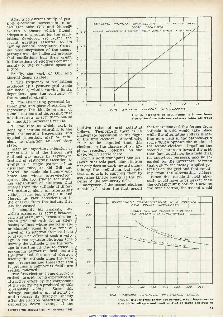
After a concurrent study of pos- sible electronic movements in an oscillator tube Gill and Morre113 evolved a theory which though adequate to account for the oscil- lations developed yet lacked the cogent qualities essential to its gaining general acceptance. Creat- ing most skepticism of the theory perhaps was the indicated premise that oscillations had their origin in the actions of electrons confined mainly to the grid -plate space of a tube.
Briefly, the work of Gill and Morrell demonstrated:
1. The frequency of oscillations produced by a positive grid triode oscillator is, within varying limits, dependent upon the constants of the connected circuit.
2. The alternating potential be- tween grid and plate electrodes, by increasing the kinetic energy of some electrons and decreasing that of others, acts to sort them out so an organized movement results.
3. The rate at which work is done by electrons returning to the grid, for certain frequencies and applied potentials, may be suffi- cient to maintain an oscillatory state.
Later an important extension or generalization of the theory just outlined was made by Llewellyn4. Instead of restricting attention to events in a single portion of an oscillator tube, as did Gill and Morrell, he made his inquiry em- brace the whole inter -electrode space. He, too, studied the work- ing capabilities of electrons that emerge from the cathode at differ- ent instants along an alternating voltage cycle, but unlike Gill and Morrell he gave consideration to the charges from the instant they left the cathode.
To simplify his analysis, Lle- wellyn assumed as acting between grid and plate, and, hence, also be- tween grid and cathode, an alter- nating voltage whose period is ap- proximately equal to the time of travel of an electron from cathode to plate. The effect of such a volt- age on two separate electrons (one leaving the cathode when the volt- age is starting its rise to create a maximum attractive field toward the grid, and the second electron leaving the cathode when the volt- age is reversing and thereafter acts to produce a subnormal field) are readily followed.
The first electron, in moving from cathode to grid, would experience an attractive effort by the component of the electric field produced by this alternating voltage. Since this voltage completes an alternation and reverses its direction shortly after the electron passes the grid, a depression below average of the
ELECTRONIC INDUSTRIES October, 1943
h 2 0
J / 6
ti
ti
/.2
0.8
0.4
o
I
OSCILLATION
(/NTENJITY
I
MEASURED
I
/NTENS/rY
/N A
I
CHARACTER/ST/C TR/OOE
RESONANT
I
OSC/LL c,Rcu,r LOOSC4V
I
OP A
A TOR
COUPLED
I
POS/T/YE
TO OJC/LLATORI
GR/O
O 2 4
TOTAL
6 8 /0 /2 /4 EM/SS/ON CURRENT (M/LL/AMPERES)
Fig. 3. Strength of oscillations is linear func- tion of total cathode current over range observed
positive value of grid potential follows. Thenceforth there is an inadequate opposition to the flight of the first electron. Accordingly, it is to be expected that this electron, in the absence of an ap- plied, repellent potential on the plate, would arrive there.
From a work standpoint one per- ceives that this particular electron not only does no work toward main- taining the oscillations but, con- trariwise, acts to suppress them by acquiring kinetic energy at the ex- pense of the oscillatory field.
Emergence of the second electron a half -cycle after the first means
W
IW
i
280
240
zoo
/60
/20
80
40
o
/6
that movement of the former from cathode to grid would take place while the alternating voltage is set- ting up a field in the cathode -grid space which opposes the motion of the second electron. Impelling the second electron on toward the grid, therefore, would now be a field that, for analytical purposes, may be re- garded as the difference between that due to the steady, applied po- tential on the grid and that result- ing from the alternating voltage.
Since this resultant field obvi- ously would have to be weaker than the corresponding one that acts on the first electron, the second would
I
WAVELENGTH I I
CHARACTER/ST/CS GR/D
AVERAGE GR/0 CURRENT
I
TR/ODE
F/LAMENT
I
OSC/LLATOR
VOLTAGE = /4 0 41/4L/AMPERES
I
OF
-
I
A POSITIVE I
4.95 VOLTS
<9T F AOTfNrq<
P<,9TE- POTCNT/qL
s0 O[7y.
voLTs
0 40 80 /20 /60 200 240 280 320 360
GR/D - CATHODE POTENT/AL DIFFERENCE (VOLTS)
Fig. 4. Higher frequencies are reached when larger nega- tive plate voltages and positive grid voltages are applied
77
www.americanradiohistory.com
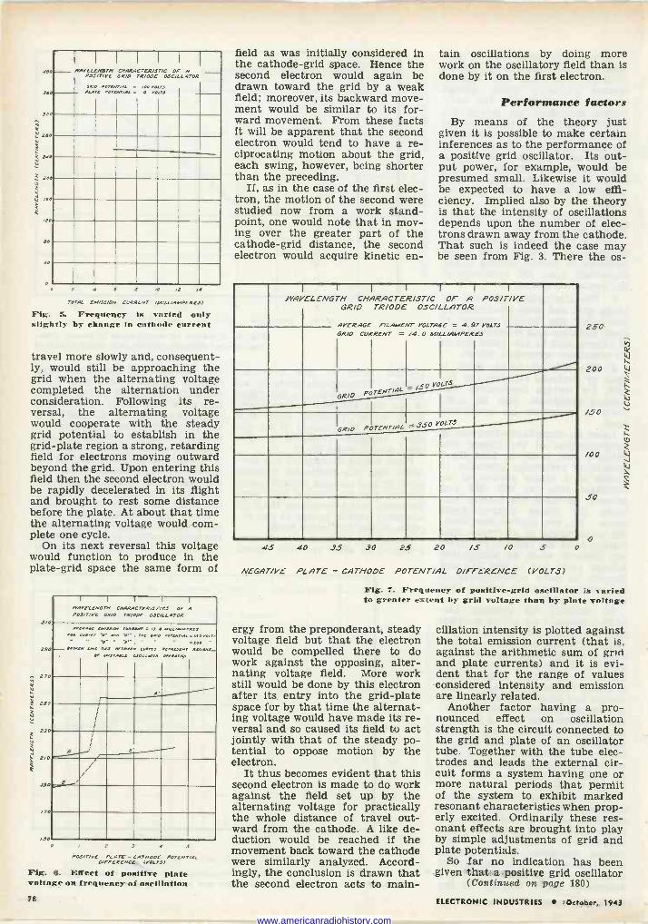
MO
760
/TAVELENG7N P03/7/9E
PNi
I
POTLVT/PL C POT[NT/AL
I
CNARACTER/S7/C GRID
= =
I
TR/ODE
NO O NOUS
I
OF OSCILLATOR
I
A I
iEO
90
ZOO
/e0
20
e0
40
0 0 2 4 6 O /0 /2 /4
TOTAL
Fig. SL Frequency is varied only slightly by change in cathode current
EM/SS/ON CURRENT (M/LL/AMPCRCS)
travel more slowly and, consequent- ly, would still be approaching the grid when the alternating voltage completed the alternation under consideration. Following its re- versal, the alternating voltage would cooperate with the steady grid potential to establish in the grid -plate region a strong, retarding field for electrons moving outward beyond the grid. Upon entering this field then the second electron would be rapidly decelerated in its flight and brought to rest some distance before the plate. At about that time the alternating voltage would com- plete one cycle.
On its next reversal this voltage would function to produce in the plate -grid space the same form of
9/
29
27
250
290
2/0
/90
/70
JO
1 I I I 1
ITAELCNG N CHARACTER/ST/CS OF A PAS/TIRE GR/O TR/ODE OSCILLATOR
. N
.. w=J"' n a Ç0133 eOlf
r
..14. . row. y.e..eNwT. _ 4eOeeH LW=R4410=3-
OP .3TA:1"E"034w : á te3/.
- ( (
I I
/
; (
(
A B
e / :/
2 4 5
POSITIVE PLATE - CATHODE POTENT/AL DIFFERENCE (COLTS)
Fig. 6. Effect of positive plate voltage on frequency of oscillation
field as was initially considered in the cathode -grid space. Hence the second electron would again be drawn toward the grid by a weak field; moreover, its backward move- ment would be similar to its for- ward movement. From these facts It will be apparent that the second electron would tend to have a re- ciprocating motion about the grid, each swing, however, being shorter than the preceding.
If, as in the case of the first elec- tron, the motion of the second were studied now from a work stand- point, one would note that in mov- ing over the greater part of the cathode -grid distance, the second electron would acquire kinetic en -
tain oscillations by doing more work on the oscillatory field than is done by it on the first electron.
Performance factors By means of the theory just
given it is possible to make certain inferences as to the performance of a positive grid oscillator. Its out- put power, for example, would be presumed small. Likewise it would be expected to have a low effi- ciency. Implied also by the theory is that the intensity of oscillations depends upon the number of elec- trons drawn away from the cathode. That such is indeed the case may be seen from Fig. 3. There the os -
WAVELENGTH I I
CHARACTER/ST/C GRID
AVERAGE GRID CURRENT
I
TR/ODE
'a...wENT =
1
OSCILLATOR
VOLTAGE
/4.0 MILL/AMPERES
I
OF A
= 4.97
I
P0S/T/VE
VOLTS
GRID POTENTIAL /,.-- 50 VOLT-
GRID POTENTIAL = 350 YOLTJ
45 40 35 30 25 20 /5 /0 5
NEGATIVE PLATE - CATHODE POTENT/AL DIFFERENCE (VOLTS)
o
250
200 4.1
/50
/00
.50
o
W
t41
Fig. 7. Frequency of positive -grid oscillator is varied to greater extent by grid voltage than by plate voltage
ergy from the preponderant, steady voltage field but that the electron would be compelled there to do work against the opposing, alter- nating voltage field. More work still would be done by this electron after its entry into the grid -plate space for by that time the alternat- ing voltage would have made its re- versal and so caused its field to act jointly with that of the steady po- tential to oppose motion by the electron.
It thus becomes evident that this second electron is made to do work against the field set up by the alternating voltage for practically the whole distance of travel out- ward from the cathode. A like de- duction would be reached if the movement back toward the cathode were similarly analyzed. Accord- ingly, the conclusion is drawn that the second electron acts to main-
cillation intensity is plotted against the total emission current (that is, against the arithmetic sum of grid and plate currents) and it is evi- dent that for the range of values considered intensity and emission are linearly related.
Another factor having a pro- nounced effect on oscillation strength is the circuit connected to the grid and plate of an oscillator tube. Together with the tube elec- trodes and leads the external cir- cuit forms a system having one or more natural periods that permit of the system to exhibit marked resonant characteristics when prop- erly excited. Ordinarily these res- onant effects are brought into play by simple adjustments of grid and plate potentials.
So far no indication has been given that a positive grid oscillator
(Continued on page 180)
78 ELECTRONIC INDUSTRIES .October, 1943
www.americanradiohistory.com
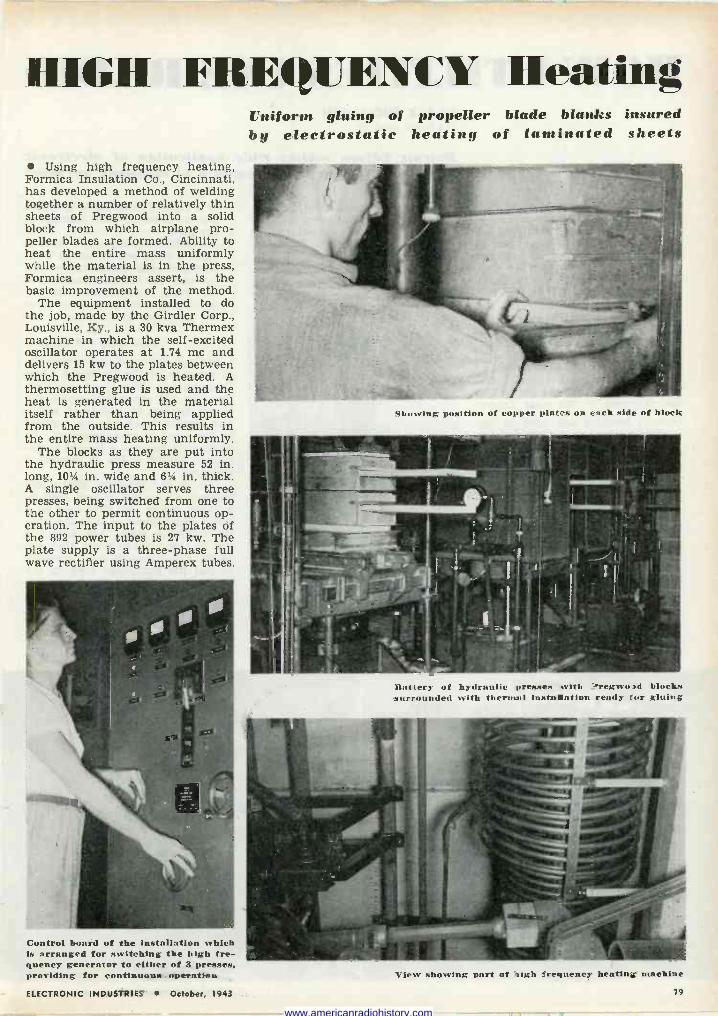
1[IGII FREQUENCY Heating
Using high frequency heating, Formica Insulation Co., Cincinnati, has developed a method of welding together a number of relatively thin sheets of Pregwood into a solid block from which airplane pro- peller blades are formed. Ability to heat the entire mass uniformly while the material is in the press, Formica engineers assert, is the basic improvement of the method.
The equipment installed to do the job, made by the Girdler Corp., Louisville, Ky., is a 30 kva Thermex machine in which the self-excited oscillator operates at 1.74 me and delivers 15 kw to the plates between which the Pregwood is heated. A thermosetting glue is used and the heat is generated in the material itself rather than being applied from the outside. This results in the entire mass heating uniformly.
The blocks as they are put into the hydraulic press measure 52 in. long, 101/4 in. wide and 61/4 in. thick. A single oscillator serves three presses, being switched from one to the other to permit continuous op- eration. The input to the plates of the 892 power tubes is 27 kw. The plate supply is a three-phase full wave rectifier using Amperex tubes.
Control board of the installation which is arranged for switching the high fre- quency generator to either of 3 presses, providing for continuous, operation
Uniform gluing of propeller blade blanks insured by electrostatic heating of laminated sheets
Showing position of copper plates on each side of block
Battery of hydraulic presses with .?regwo3d blocks surrounded with thermal installation ready for gluing
View showing part of high frequency heating machine
ELECTRONIC INDUSTRIES October, 1943 79
www.americanradiohistory.com
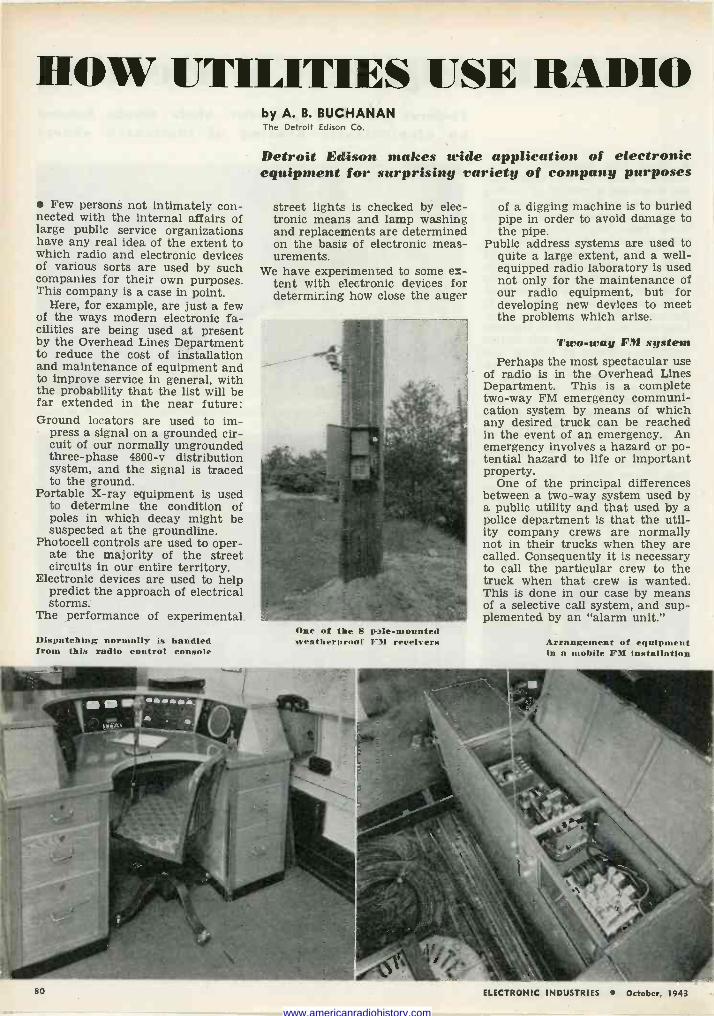
HOW UTILITIES USE RADIO
Few persons not intimately con- nected with the internal affairs of large public service organizations have any real idea of the extent to which radio and electronic devices of various sorts are used by such companies for their own purposes. This company is a case in point.
Here, for example, are just a few of the ways modern electronic fa- cilities are being used at present by the Overhead Lines Department to reduce the cost of installation and maintenance of equipment and to improve service in general, with the probability that the list will be far extended in the near future: Ground locators are used to im-
press a signal on a grounded cir- cuit of our normally ungrounded three-phase 4800-v distribution system, and the signal is traced to the ground.
Portable X-ray equipment is used to determine the condition of poles in which decay might be suspected at the groundline.
Photocell controls are used to oper- ate the majority of the street circuits in our entire territory.
Electronic devices are used to help predict the approach of electrical storms.
The performance of experimental
Dispatching normally is handled frocs this radio control console
by A. B. BUCHANAN The Detroit Edison Co.
Detroit Edison makes wide application of electronic equipment for surprising variety of company purposes
street lights is checked by elec- tronic means and lamp washing and replacements are determined on the basis of electronic meas- urements.
We have experimented to some ex- tent with electronic devices for determining how close the auger
One of the S pole -mounted weatherproof FM receivers
of a digging machine is to buried pipe in order to avoid damage to the pipe.
Public address systems are used to quite a large extent, and a well- equipped radio laboratory is used not only for the maintenance of our radio equipment, but for developing new devices to meet the problems which arise.
Two-way FM system Perhaps the most spectacular use
of radio is in the Overhead Lines Department. This is a complete two-way FM emergency communi- cation system by means of which any desired truck can be reached in the event of an emergency. An emergency involves a hazard or po- tential hazard to life or important property.
One of the principal differences between a two-way system used by a public utility and that used by a police department is that the util- ity company crews are normally not in their trucks when they are called. Consequently it is necessary to call the particular crew to the truck when that crew is wanted. This is done in our case by means of a selective call system, and sup- plemented by an "alarm unit."
Arrangement of equipment in a mobile FM installation
ELECTRONIC INDUSTRIES October, 1943
www.americanradiohistory.com
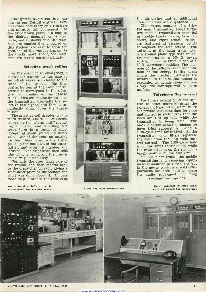
The system, at present, is in use only in our Detroit district. Sev- eral other cars carry only receivers and selective call equipment. At the dispatching point is a map of the district mounted on a steel plate, and a number of Alnico mag- nats are numbered and placed on this steel -backed map to show the positions of the various trucks. As the trucks move about, the mag- nats are moved correspondingly.
Selective truck calling
In the event of an emergency, a dispatcher glances at the map to see which crews are closest to the scene of the trouble. He then pushes buttons at the radio control console to correspond to the selec- tive call number of the desired truck. This automatically turns on the transmitter, transmits the se- lective call signal, and then auto- matically shuts down the trans- mitter.
The selective call decoder, on the truck wanted, closes a 6-v circuit, energizing the "alarm unit," sound- ing a buzzer, and sounding the truck horn in a series of short "beeps" at about six second inter- vals. One of the crew, on hearing his horn blow, goes to the truck, picks up the hand set of his trans- mitter, and gives his number and location. The dispatcher then tells him what is wrong and the crew is on its way immediately.
Normally the crew takes care of the trouble and then reports back to the dispatcher by radio giving a brief description of the trouble and what was done about it. In case more help is needed the crew calls
An extensive laboratory is maintained for service work 3 kw FM malm transmitter
the dispatcher and an additional crew or crews are dispatched.
The system consists of a 3 -kw FM main transmitter, about forty- five mobile transmitters mounted in trouble trucks having two -man crews, and eight remote receiv- ers scattered at strategic points throughout the area served. The antenna at the main transmitter is a ground plane type with reflec- tor mounted on a 200 ft. tower, which, in turn, is built on top of a 30 ft. warehouse building. The pur- pose of the reflector is to send the bulk of the energy to the north where the greatest distances are involved, so that as the system is expanded to include suburban ter- ritory, the coverage will be more uniform.
Telephone line control For future expansion of the sys-
tem to other districts, using the same main transmitter, we must use our private telephone lines for voice and control in such a way that the lines are tied up only while the transmitter is being used. The block diagram shows a scheme we have tried successfully, using a 1000 -cycle tone for control. At the transmitter end, filters separate the voice from the 1000 -cycle con- trol current. The 1000 -cycle tone is on the wires continuously while the transmitter is on the air, but is barely audible in the receivers.
On our older trucks the mobile transmitting and receiving equip- ment is mounted in a steel box, but in the newer trucks a special com- partment has been built to house the radio equipment, including
(Continued on page 154)
Main transmitter with local control console for emergency
ELECTRONIC INDUSTRIES October. 1943 81
www.americanradiohistory.com
POSTWAR RADIO SETS Well-known industrial designers express their views on principles which will control design. See market for 16-20 million sets
If civilian -radio production should start within a year, the radio industry will face a delayed demand of nearly fifty million sets! Such a figure is easily justified by our 14 -million -set production in 1941- the last year civilian -radio manufacturing was per- mitted to operate full -tilt.
Industry leaders will not be surprised then, if the first years of postwar radio manufacture roll up an- nual totals of 16 to 20 million receivers. This is mass production on a scale equalled or approached by no other comparable product in civilian life.
Experience in mass production of automobiles, elec- trical appliances, office equipment, and also radio, has indicated that mass demand for a product can be greatly stimulated and increased by physical designs which appeal to buyers, and particularly to women.
Good engineering principles and tone quality alone, it appears, are not sufficient for commercial success with a home radio that seeks a huge mass market.
Radio -Tele -Recording by RAYMOND LOEWY 580 Fifth Avenue, New York, N. Y.
Shown herewith is a combina- tion radio, television and recording unit, designed for the Continental Radio & Television Corp.
The unit is operated directly by push-button or by remote control, a detail of which is encircled. This remote control can regulate vol- ume, tone and tuning of radio and television units. Records are set up in vertical position, as many as thirty at a time. A system of dual tone arms plays both sides in or- der. Additional records are stored in drawer space at each side of the cabinet.
Precision Instrument by GILBERT ROHDE Bay Drive, Huntington, L. I., N. Y.
After the war, design-formerly stifled and twisted in the radio field-will be free to function here as it has so successfully in other industries.
My prediction is that even the larger cabinets for radio will no longer masquerade as a chest of drawers or a sewing cabinet. Manu- facturers will no longer have to tell their designers to "make a cabinet as Chippendale would have made it, if there had been radio in his day."
The radio will be an instrument in its own right. The predominat- ing feeling that instrument is to convey is one of precision. The cabinet must say - "I am a fine
In addition there must be attractive outlines, artistic design, appealing new materials and color combina- tions, and convenience of control,-from the stand- point of the customer.
It was the introduction of these elements by skilled industrial designers (who at the time may have known little about radio) which resulted in the sudden spurt in the radio -set sales curve ten years ago.
In the decade since, radio production has enjoyed the attention and ministrations of these industrial designers, whose ideas have supplemented the basic engineering design and have resulted in many desirable new selling features.
Recognizing that a new and outstanding era of civilian -radio production may be upon us before very long, the editors of "Electronic Industries" have in- vited representative industrial designers to let us pub- lish their comments on the directions which postwar civilian radio should take.
piece of engineering; I get all the music to you just as it was played; I am a precision instrument." Psy- chologically, we will have been pre- pared for such a machine, for thousands of our young men, and now young women too, have been exposed to the trim and business- like appearance of radio in mili- tary units, the radio and instru- ment panels in airplanes.
Of course we can't do the job by transplanting an airplane radio case, lock, stock and barrel, into the front parlor. It will take very competent design to embody in one unit, the feeling of precision found in the military radio and also the feeling that this instrument be- longs in a home.
Civilian Walkie-Talkie by MONTGOMERY FERAR Sundberg-Ferar, Detroit
The Walkie-Talkie radio trans- mitter and receiver is our sugges- tion for a future radio design.
Applications of this compact, plastic -cased Walkie-Talkie in pro-
viding two-way wireless communi- cation are almost unlimited. A few of the most obvious uses would be for plant executives, construction gangs, firemen, police, forest rang- ers and farmers or ranchers.
The design utilizes a carrying strap as the antenna. A conven- tional head set is provided which houses the microphone and re- ceiver. A loud speaker can be switched on or off as desired.
We think this application of a wartime development will be an extremely useful contribution to communication in the postwar world.
Esthetics and Values by JOHN VASSOS (Major, Corps of Engineers), Norwalk, Conn. Former RCA Consultant
Radio and television after the war will change little in principle. Added facilities, naturally, will be incorporated, without making the device a "Rube Goldberg" affair.
The time element which is so re- lated to the function of radio will
JIIIIIIIIIIIIIUIIIIIIIIIIIIIIhIIIIuIllllllli
E --> E
..II IIIIIIIIIIIIIIIIIIIIIIIIIIIIIIIIIIIIIIIIIIIIIilllllllllllll IIIIIIIIIIIIIIIIIIII!II IIIIIIIIIql1111111111141!Illllllilllllillllllll III lltllllllll lllllllllll!I IIIIIIIIIIIIIIIIIIIIIIIIIIIIIIIIIIIIIIIIIIIIUtUIIIIIII11111UIIIIII111111111111111UItIIIUI11Uli
1. 1.0E WY-"C41111 binn tion radio, television and recording unit." 2. FERAR-The Walkie-Talkie ... will be a wartime development." 3. DREYER-"With function its first consideration." 4. LESCAZE- "Formed by three basic units." 5. JENSE -"A music lover's instru- ment." 6. ROHDE-"Postwar set that will not be produced."
82 ELECTRONIC INDUSTRIES October, 1943
www.americanradiohistory.com
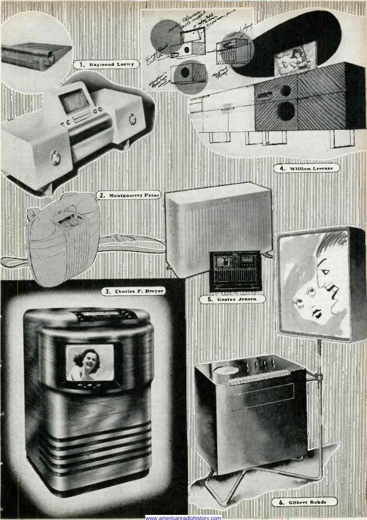
Raymond Loewy
RIIII11111111111111111111111111111111111111111111111111111111111111111111111111111111
''!il
. Montgomery Fern/
Illlllllllllll1lillllll
IIIIIIIIIuiulllullliiullllllllllll
Elllllliüiiïiuu
4. William Lenenze
Gilbert Rohde
lJ iii www.americanradiohistory.com
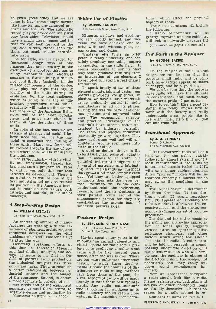
be given great study and we are going to have some unique devices like time -tuning, pre -arranged pro- grams and the like. The automatic record -playing device definitely will play both sides. Television should have a much larger image and for that we can look forward to the projected screen, rather than the sharp but much smaller cathode - tube screen.
As for style, we are headed for functional design with all the nuances that are necessary in the evolution of a product that has so many mechanical and electrical accessories. Streamlining, although not contributing basically to the related components of the device, may play the highlights styling identity of the units during its evolution. For the great audience, which is going to be the middle bracket, progressive units which eventually will make up the decora- tive scheme of the American living room will be the most popular items and great care should be taken in the designing of these units.
In spite of the fact that we are talking of plastics and metal, I be- lieve wood still will be the ma- terial to construct the housing of these units. Many new forms will be evolved through the use of ply- wood where costs will be reduced to the minimum.
The radio industry with its vital- ity and imagination, already had launched such a program as I refer to and it was only this war that arrested its development. There is no question it will be one of the first industries not only to reclaim its position in the American home but to establish new values, both esthetic and material, in our life of tomorrow.
A Step -by -Step Design by WILLIAM LESCAZE 211 East 48th Street, New York, N. Y.
An increasing number of manu- facturers are working with the as- sistance of planners, architects, and industrial designers on the vital problems which will confront all of us after the war.
Generally speaking, efforts at this time are threefold: research and fact-finding, analysis, and de- sign. It seems to me that in the field of postwar radio production, the industrial designer has three important tasks. First, to establish a better relationship between in- dustrial technic and the budget of the consumer. Second, to obtain a more accurate knowledge of con- sumer needs and of the equipment necessary to meet them. Third, to integrate design and production by
(Continued on pages 148 and 150)
Wider Use of Plastics by MORRIS SANDERS 219 East 49th Street, New York, N. Y.
Hitherto, we have had good ra- dio sets poorly housed, and vice versa. We have achieved our re- sults with and without plan, or- ganization, and design.
Whatever else turns up after peace is really underway, one can safely prophesy one thing-superb competition in the radio field. It seems reasonable to assume that only those products resulting from an integration of the elements I have noted will stand a real chance for success.
To speak briefly of two of those elements, materials and design, our postwar prospects are splendid. In plastics, we have a large materials group eminently suited to radio manufacture in all of its phases. During the war we have developed new plastics and improved older ones. The economical, saleable, and practical advantages of the materials have become better un- derstood by industry, generally. The radio and plastics industries practically grew up together. They know each other well and will un- doubtedly become even more inti- mate in the future.
A word on design-design in the Oxford Dictionary sense of "adapta- tion of means to an end": our qualified industrial designers face a world of materials and fabricat- ing and merchandising methods that grows a bit more complex each day. Yet they are better equipped to handle their jobs than ever be- fore. Fortunate will be the com- panies that relate the engineering, research, and design electrons in their parallel orbits around the management proton for they are constructing the atomic base of successful postwar sales.
Postwar Design by BENJAMIN SIDNEY NASH 51 Fifth Avenue, New York, N. Y. Former Philco Consultant
Having spent many years in de- veloping the annual cabinetry and visual aspects for radio sets, I pre- fer not to predict or visualize what radio will be like, several years hence, after the war is over. There are too many influences other than design, to guide these develop- ments. Should the channels of dis- tribution or radio selling methods vary from those of the past, the visual aspects of radio will be made exactly to meet these new require- ments. Any radio manufacturèr who is looking for guidance as to radio cabinetry should keep a close watch on the oncoming "considera-
tions" which affect the physical aspects of radio.
These considerations will include the following:
1. Radio performance will be greatly improved and the cabinetry will seek to outwardly visualize the
(Continued on pages 148 and 150)
Put Faith in the Designer by GEORGE SAKIER
9 East 57th Street, New York, N. Y.
On the subject of radio cabinet design, we can be sure that the postwar small radio will be com- pact, have gadget appeal, be smart or snappy, and be a good buy.
We can be sure that the postwar large radio will have the ultimate in conveniences and must satisfy the owner's pride of possession.
How to get this? Hire a good de- signer who really knows how to work with the factory and really understands what people like to live with. Then help him all you can and trust him.
Functional Approach by J. O. REINECKE Barnes G Reinecke 664 N. Michigan Ave., Chicago
I fear tomorrow's radio will be a let -down for the public, quickly followed by almost extreme models. Most manufacturers are thinking in terms of chassis tooled in 1941, with only minor cabinet changes. A few "pioneer" models will be in- troduced creating a market which may swing the pendulum to the left.
The logical design is determined by three elements: (1) the elec- tronic unit, (2) sound reproduc- tion, (3) appearance. Probably the richest market lies between the ex- pensive model, and the cheap, eco- nomically -dangerous set of poor re- production.
The demand for better music by the public and a growing apprecia- tion of tonal quality, suggests greater stress on speaker quality, resonance chambers, and other factors which affect the audible elements of a radio. Greater stress will be laid on research in sound, possibly under the direction of a competent musician who will com- plement the engineer in charge of the electronic unit. Knowledge, not necessarily cost, may easily im- prove sound reproduction im- mensely.
From an appearance viewpoint a radio should look like a radio. Pianos, refrigerators, bathtubs, and designs of other household items are frankly themselves. There is no reason for a radio cabinet to re -
(Continued on pages 148 and 150) 84 ELECTRONIC INDUSTRIES October, 1943
www.americanradiohistory.com
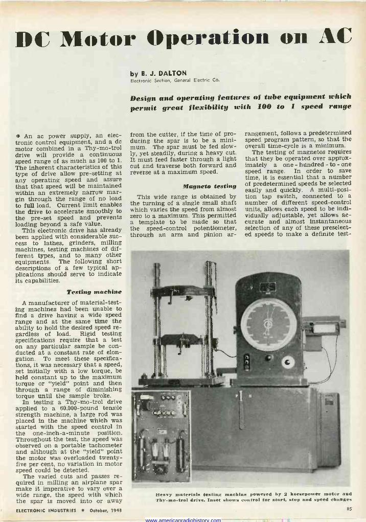
DC Motor Operation on AC
An ac power supply, an elec- tronic control equipment, and a do motor combined in a Thy-mo-trol drive will provide a continuous speed range of as much as 100 to 1.
The inherent characteristics of this type of drive allow pre-setting at any operating speed and assure that that speed will be maintained within an extremely narrow mar- gin through the range of no load to full load. Current limit enables the drive to accelerate smoothly to the pre-set speed and prevents loading beyond a safe value.
This electronic drive has already been applied with considerable suc- cess to lathes, grinders, milling machines, testing machines of dif- ferent types, and to many other equipments. The following short descriptions of a few typical ap- plications should serve to indicate its capabilities.
Testing machine
A manufacturer of material -test- ing machines had been unable to find a drive having a wide speed range and at the same time the ability to hold the desired speed re- gardless of load. Rigid testing specifications require that a test on any particular sample be con- ducted at a constant rate of elon- gation. To meet these specifica- tions, it was necessary that a speed, set initially with a low torque, be held constant up to the maximum torque or "yield" point and then through a range of diminishing torque until the sample broke.
In testing a Thy-mo-trol drive applied to a 60.000 -pound tensile strength machine, a large rod was placed in the machine which was started with the speed control in the one -inch -a -minute position. Throughout the test, the speed was observed on a portable tachometer and although at the "yield" point the motor was overloaded twenty- five per cent, no variation in motor speed could be detected.
The varied cuts and passes re- quired in milling an airplane spar make it imperative to vary over a wide range, the speed with which the spar is moved into or away
by B. J. DALTON Electronic Section, General Electric Co.
Design and operating features of tube equipment which permit great flexibility with 100 to 1 speed range
from the cutter, if the time of pro- ducing the spar is to be a mini- mum. The spar must be fed slow- ly, yet steadily, during a heavy cut. It must feed faster through a light cut and traverse both forward and reverse at a maximum speed.
Magneto testing This wide range is obtained by
the turning of a single small shaft which varies the speed from almost zero to a maximum. This permitted a template to be made so that the speed -control potentiometer, through an arm and pinion ar-
rangement, follows a predetermined speed program pattern, so that the overall time -cycle is a minimum.
The testing of magnetos requires that they be operated over approx- imately a one - hundred - to - one speed range. In order to save time, it is essential that a number of predetermined speeds be selected easily and quickly. A multi -posi- tion tap switch, connected to a number of different speed -control units, allows each speed to be indi- vidually adjustable, yet allows ac- curate and almost instantaneous selection of any of these preselect- ed speeds to make a definite test -
Heavy materials testing machine powered by 2 horsepower motor and Thy-mo-trol drive. Inset shows control for start, stop and speed changes
ELECTRONIC INDUSTRIES October, 1943 85
www.americanradiohistory.com
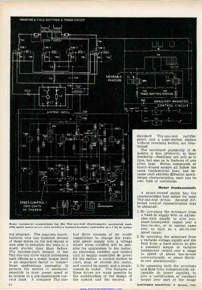
ARMATURE & FIELD RECTIFIER & POWER CIRCUIT
SRF f- TUBE FPL
SATURABLE REACTORS
IR COM PFNSAT ION
FPR 'ry
Basic equipment connections for the Thy-mo-trol electronically controlled vari- able speed tor drive. with auxiliary control features applicable to a 1 hp do motor
ing program. The magneto manu- facturer who has installed several of these drives on his test stands is now able to complete the tests in a much shorter time than before. The current -limit feature of the Thy-mo-trol drive which introduces such effects as a motor torque limit is an important factor in makin' these applications successful. It permits the motors to accelerate smoothly to their preset speed or to reverse at a pre -determined cur- rent limit. A complete Thy-mo-
trol drive consists of an anode transformer to change the avail- able power supply into a voltage which when rectified will be suit- able for application to the motor; an electronic rectifier and control unit to supply controlled dc power for the motor; a control station to start, stop, or reverse the motor, and control its speed; and a shunt- wound dc motor. The features of these drives are made possible by the coordination of the design of the motors and the control. A
v\_nn ,VW. _ T3P T4P
PHASE SHIFTING BRIDGE
standard Thy-mo-trol rectifier panel, and a push-button station without reversing button, are illus- trated.
The continued popularity of do motors is due, primarily, to their flexibility-flexibility not only as to type, but also as to features of any given type. Series, compound, or shunt-wound motors all follow the same fundamental laws, but, be- cause each exhibits different speed - torque characteristics, each has its own field of usefulness.
Motor fundamentals A shunt-wound motor has the
characteristics best suited for most Thy-mo-trol drives. Several dif- ferent control characteristics may be obtained: 1. By operating the armature from
a fixed do supply with an adjust- able -field supply to give con- stant -horsepower output over a four -to -one, or in special cases over as high as a six -to -one speed range;
2. By operating the armature from a variable -voltage supply and the field from a fixed source to give a constant torque or variable horsepower output over a range in speed of about ten -to -one conventionally, or about thirty - to -one electronically;
3. By operating both the armature and field from independently ad- justable do power supplies, to give a combination of constant torque over part of the range
B.i ELECTRONIC INDUSTRIES October, 1943
www.americanradiohistory.com
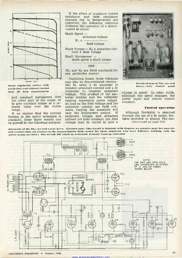
..l
100
80
.0
5 r 40
ro
-`--_ ... ..
...., .... r"`................. ...... -
PERCENT LOAD
Speed regulation curves with (solid line) and without (dotted line) IR drop compensation
and constant horsepower over the other part of the range, or to give constant torque at a re- duced value over the entire range. If we assume that the current
flowing in the motor armature is constant, these three results can be proved by the following analysis.
If the effect of armature circuit resistance and field resistance changes due to temperature are neglected, the following relations illustrate the operation of a shunt- wound dc motor: Shaft Speed =
armature voltage K1 x
field voltage
Shaft Torque = K2 x armature cur- rent x field voltage
Shaft Horsepower = shaft speed x shaft torque
5250
(K1 and K2 are fixed constants ,for any particular motor)
Neglecting losses, these relations may also be demonstrated electric- ally by using a dc ammeter to measure armature current and a dc voltmeter to measure armature voltage. The product of the am- meter reading and the voltmeter reading represents power output. As long as the field voltage and the armature current are held con- Control operation stant, varying the armature will vary the horsepower output. If Although flexibility is obtained armature voltage and armature through the use of a dc motor, fea - current are held constant, the field tures provided in typical Thy-mo- voltage may be varied to give a (Continued on page 174)
Standard type Of Thy- -1 rol henry - duty control panel
change in speed. In other words, although the speed changes, the power input and output remain constant.
Schematic of the Thy-mo-trol tor drive. (Editor's note: This circuit is identical with diagram on opposite page but uses cir- cuit symbols that are common to the communication field-added for those engineers who have difficulty working with the
er group symbols.) The switch 1)11 refers to automatic dynamic braking contactor
T3
.0O03019Qºjöäs 4. TI
T4
SRF
.OQ9QQ r r' 00 00
L.D QQSLQ
r606.06
TH I
le* -
T:Eb
0121QOERIES
dF
a
00 00' T5
o -VNVNP
TH 2
Y ( T) Y
TH 3
SRA
NOTE; THE SRF AND SRA COILS ARE CONNECTED TO PLATES OF D AND DD TUBES SHOWN BELOW.
F 1
DD
SPEED RANGE
S EED DB
ELECTRONIC INDUSTRIES October, 1943 87
www.americanradiohistory.com
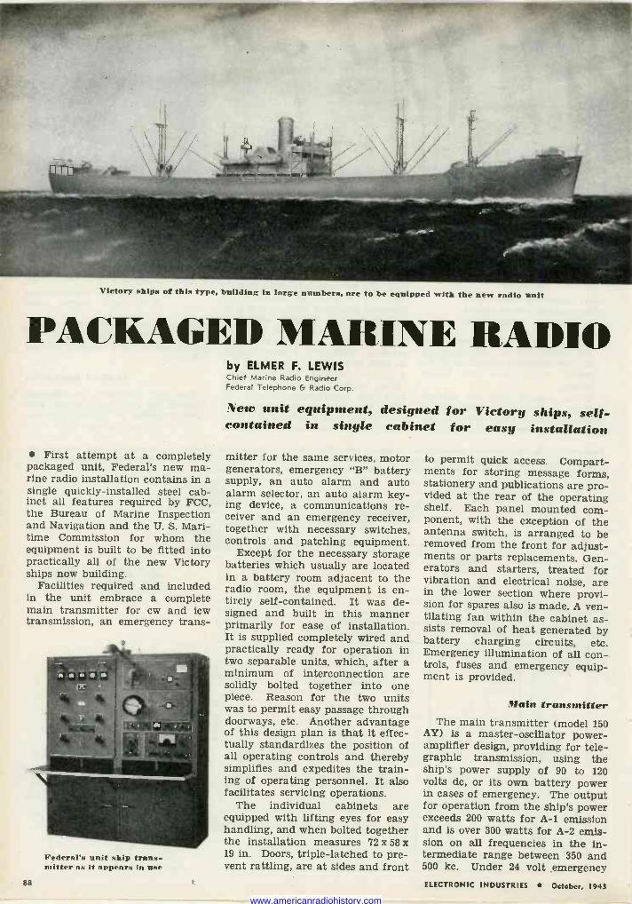
Victory ships of this type, building in large numbers, are to be equipped with the new radio unit
I'ICKAGED MARINE. RADIO
First attempt at a completely packaged unit, Federal's new ma- rine radio installation contains in a single quickly -installed steel cab- inet all features required by FCC, the Bureau of Marine Inspection and Navigation and the U. S. Mari- time Commission for whom the equipment is built to be fitted into practically all of the new Victory ships now building.
Facilities required and included in the unit embrace a complete main transmitter for cw and icw transmission, an emergency trans-
Federal's unit ship trans- mitter as it appears in use
88
by ELMER F. LEWIS Chief Manne Radio Engineer Federal Telephone & Radio Corp.
New unit equipment, designed for Victory ships, self- contained in single cabinet for easy installation
mitter for the same services, motor generators, emergency "B" battery supply, an auto alarm and auto alarm selector, an auto alarm key- ing device, a communications re- ceiver and an emergency receiver, together with necessary switches, controls and patching equipment.
Except for the necessary storage batteries which usually are located in a battery room adjacent to the radio room, the equipment is en- tirely self-contained. It was de- signed and built in this manner primarily for ease of installation. It is supplied completely wired and practically ready for operation in two separable units, which, after a minimum of interconnection are solidly bolted together into one piece. Reason for the two units was to permit easy passage through doorways, etc. Another advantage of this design plan is that it effec- tually standardizes the position of all operating controls and thereby simplifies and expedites the train- ing of operating personnel. It also facilitates servicing operations.
The individual cabinets are equipped with lifting eyes for easy handling, and when bolted together the installation measures 72 x 58 x 19 in. Doors, triple -latched to pre- vent rattling, are at sides and front
to permit quick access. Compart- ments for storing message forms, stationery and publications are pro- vided at the rear of the operating shelf. Each panel mounted com- ponent, with the exception of the antenna switch, is arranged to be removed from the front for adjust- ments or parts replacements. Gen- erators and starters, treated for vibration and electrical noise, are in the lower section where provi- sion for spares also is made. A ven- tilating fan within the cabinet as- sists removal of heat generated by battery charging circuits, etc. Emergency illumination of all con- trols, fuses and emergency equip- ment is provided.
Main transmitter The main transmitter (model 150
AY) is a master -oscillator power - amplifier design, providing for tele- graphic transmission, using the ship's power supply of 90 to 120 volts dc, or its own battery power in cases of emergency. The output for operation from the ship's power exceeds 200 watts for A-1 emission and is over 300 watts for A-2 emis- sion on all frequencies in the in- termediate range between 350 and 500 kc. Under 24 volt emergency ELECTRONIC INDUSTRIES October, 1943
www.americanradiohistory.com
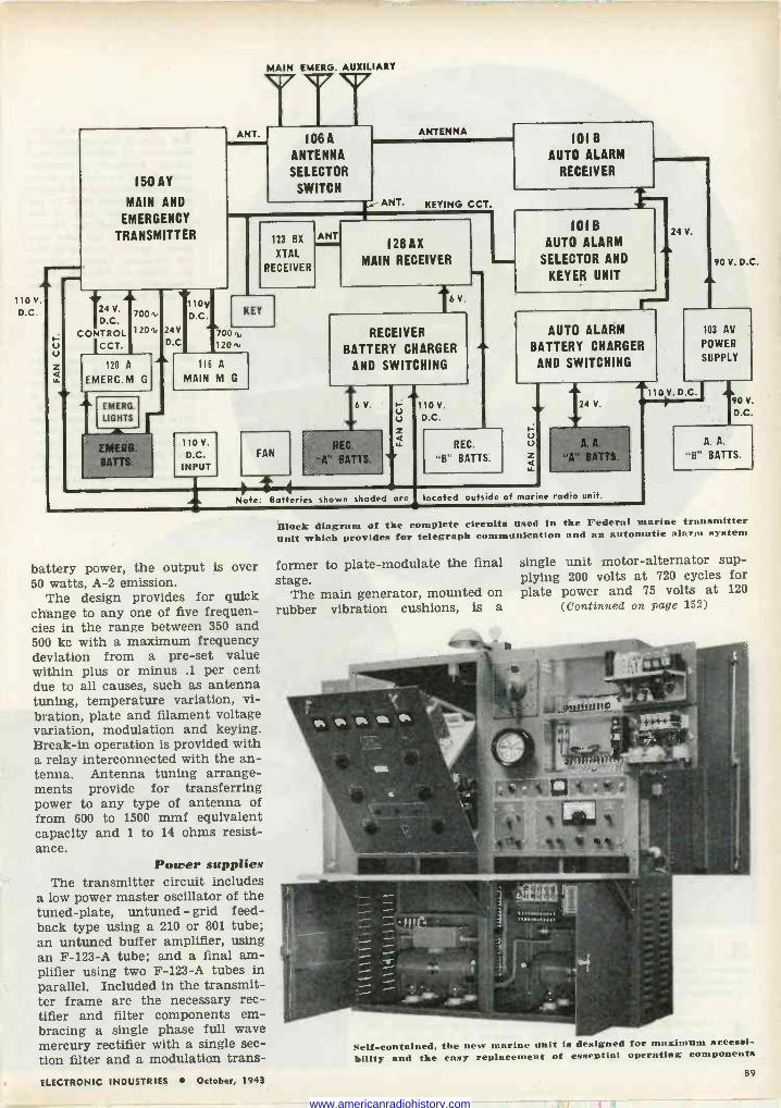
MAIN EIMERG. AUXILIARY
43,
110 V.
D.0
u u z LL
150 AY
MAIN AND
EMERGENCY
TRANSMITTER
ANT. 106 A
ANTENNA
SELECTOR
SWITCH
ANTENNA
ANT. KEYING CCT.
124 V. 7001"
D.C.
CONTROL 1201"
ICCT.
120 A
EMERG.M G
24V D.0
123 BX
XTAL
RECEIVER
ANT
110V D.C.
7 001, 120n,
KEY
116 A
MAIN M G
110 V.
D.C. INPUT
FAN
Note
battery power, the output is over 50 watts, A-2 emission.
The design provides for quick change to any one of five frequen- cies in the range between 350 and 500 kc with a maximum frequency deviation from a pre-set value within plus or minus .1 per cent due to all causes, such as antenna tuning, temperature variation, vi- bration, plate and filament voltage variation, modulation and keying. Break-in operation is provided with a relay interconnected with the an- tenna. Antenna tuning arrange- ments provide for transferring power to any type of antenna of from 600 to 1500 mmf equivalent capacity and 1 to 14 ohms resist- ance.
Power supplies The transmitter circuit includes
a low power master oscillator of the tuned -plate, untuned - grid feed- back type using a 210 or 801 tube; an untuned buffer amplifier, using an F -123-A tube; and a final am- plifier using two F -123-A tubes in parallel. Included in the transmit- ter frame are the necessary rec- tifier and filter components em- bracing a single phase full wave mercury rectifier with a single sec- tion filter and a modulation trans -
128 AX
MAIN RECEIVER
t6 V.
RECEIVER
BATTERY CHARGER
AND SWITCHING
6 V.
REC.
"A" BATTS.
u z Q LL
110 V.
D.C.
REC.
"B" BATTS.
101 B
AUTO ALARM
RECEIVER
IOI B
AUTO ALARM
SELECTOR AND
KEYER UNIT
24 V.
alk
It- AUTO ALARM
BATTERY CHARGER
AND SWITCHING
u u z LL
90 V. D.C.
103 AV
POWER
SUPPLY
aa 110 V. D.0
24 V.
Batteries shown shaded are located outside of marine radio unit.
90 V
D.C.
A. A.
"B" BATTS.
Block diagram of the complete circuits used in the Federal marine transmitter unit which provides for telegraph communication and an automatic alarm system
former to plate -modulate the final stage.
The main generator, mounted on rubber vibration cushions, is a
single unit motor -alternator sup- plying 200 volts at 720 cycles for plate power and 75 volts at 120
(Continued on page 152)
Self-contained, the new marine unit is designed for maximum accessi- bility and the easy replacement of essential operating components
89 ELECTRONIC INDUSTRIES October, 1943
www.americanradiohistory.com
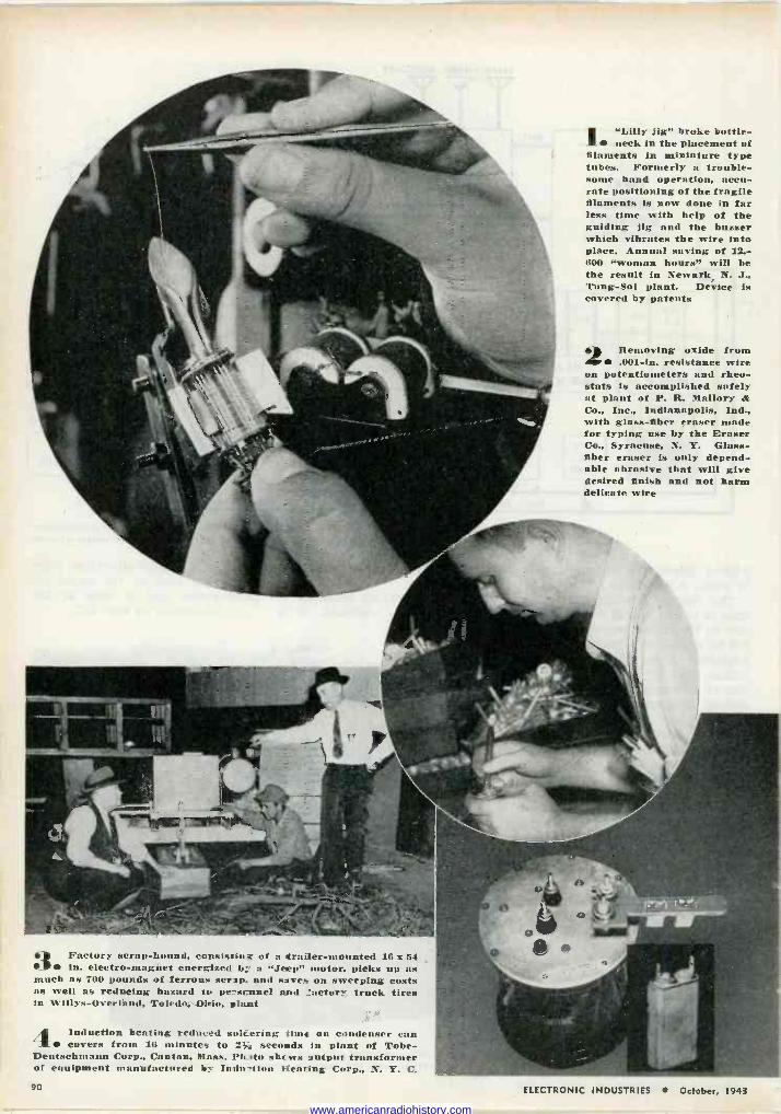
le Factory scrap -hound, consistin; of a trailer -mounted 16x64 MP in. electro-magñet energized b' a "Jeep" motor, picks up as much as 700 pounds of ferrous scrip, and saves on sweeping costs as well as reducing hazard to perscnnel and factory truck tires in Willys-Overland, Toledo,,Ohio, plant
Induction heating reduced soli ering time on condenser can covers from 16 minutes to Sÿ;í seconds in plant of Tobe-
Deutschniann Corp., Canton, Mass. Photo shows autput transformer of equipment manufactured by Induction Heating Corp., N. Y. C.
"Lilly jig" broke bottle- neck in the placement of
filaments in miniature type tubes. Formerly a trouble- some hand operation, accu- rate positioning of the fragile filaments is now done in far less time with help of the guiding Jig and the buzzer which vibrates the wire into place. Annual saving of 12,- 600 "woman hours" will be the result in Newark N. J., Tung -Sol plant. Device is covered by patents
2 Removing oxide from .001 -in. resistance wire
on potentiometers and rheo- stats is accomplished safely at plant of P. R. Mallory & Co., Inc., Indianapolis, Ind., with glass -fiber eraser made for typing use by the E Co., Syracuse, N. Y. Glass - fiber eraser is only depend- able abrasive that will give desired finish and not harm delicate wire
90 ELECTRONIC INDUSTRIES October, 1943
www.americanradiohistory.com
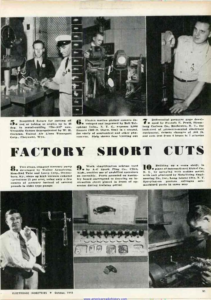
e Simplified fixture for cutting off f7 rod or tubing at angles up to 45 deg. in metal -cutting "Do -Ali" saw. Versatile fixture demonstrated by W. H. Cochran, United Air Lines Transport Corp., Cheyenne, Wyo.
bFastax motion picture ramera de- veloped and improved by Bell Tel-
ephone Labs., N. Y. C., exposes 8,000 frames (200 ft. IOmm. film) in a second, for study of mechanical and other phe- nomena. Strip shows fuse blowing out
Differential pressure gage devel- oped by Francis E. Pratt, Strom-
berg Carlson Co., Rochester, N. Y., for leak -test of pressure -sealed electronic equipment, detects changes of .001 lb. and cuts test frene 4 hours te 7 minutes
FACTORY SHORT CUTS Two stage, compact mercury pump 8 developed by Walter Armstrong,
Ken -Rad Tube and Lamp Corp., Owens- boro, Ky., steps up high vacuum exhaust operations 25 per cent, using only a few ounces of mercury instead of several pounds in older type pumps
Ay Work simplification scheme used V by A -C Spark Plug Co., Flint, Mich., enables use of unskilled operators on assembly. Parts mounted on assem- bly board correspond to drawing on in- struction chart placed in front of op- erator during training period
10 Building up a worn shaft, in plant of International Nickel Co.,
N. Y. by spraying with molten metal, with unit produced by Metallizing Engi- neering Co., Inc.., Long Island City, N. Y. Spraying -on process salvages mis - machined parts in name way
ELECTRONIC INDUSTRIES October, 1943
in 1 r Il
91
www.americanradiohistory.com
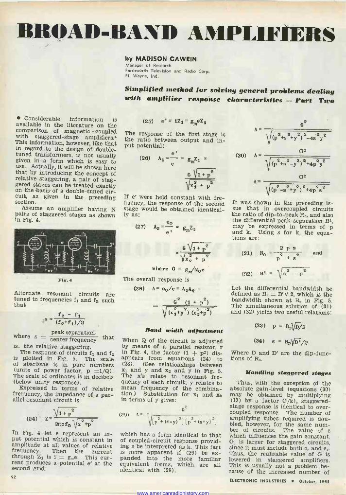
BROAD -BAND Ab1Pl.1FIE1tS
Considerable information is available in the literature on the comparison of magnetic - coupled with staggered -stage amplifiers.4 This information, however, like that in regard to the design of double - tuned transformers, is not usually given in a form which is easy to use. Actually, it will be shown here that by introducing the concept of relative staggering, a pair of stag- gered stages can be treated exactly on the basis, of a double -tuned cir- cuit, as given in the preceding section.
Assume an amplifier having N pairs of staggered stages as shown in Fig. 4.
Fig. 4
Alternate resonant circuits are tuned to frequencies f1 and f2i such that
f2 - f1 s- (f2+fi)/2
where s = peak separation that center frequency
is: the relative staggering. The response of circuits f1 and f2
is plotted in Fig. 5. The scale of abscissae is in pure numbers (units of power factor, p =1/Q). The scale of ordinates is in decibels (below unity response).
Expressed in terms of relative frequency, the impedance of a par- allel resonant circuit is
-\/1 + p2 (24) Z-
2rtc fa Vx2+p2 In Fig. 4 let e represent an in- put potential which is constant in amplitude at all values of relative frequency. Then the current through Z1 is i = ge. This cur- rent produces a potential e' at the second grid: 92
by MADISON CAWEIN Manager of Research Farnsworth Television and Radio Corp. Ft. Wayne, Ind.
Simplified method for solving general problems dealing with amplifier response characteristics - Part Two
(25) e = iZi = gmeZi
The response of the first stage is the ratio between output and in- put potential:
e' (28) Al =-= gmZi =
e
G 317.+p2 2 2 xi+p
If e' were held constant with fre- quency, the response of the second stage would be obtained identical- ly as:
e (27) A2 = = gmZ2 e'
G i+2 2
where G = gm/woe
The overall response is
(28) A= eo/e = A1A2
62 (1 + p2)
V (xi+p2) (x22 +p2)
Band width adjustment When Q of the circuit is adjusted by means of a parallel resistor, r in Fig. 4, the factor (1 + p2) dis- appears from equations (24) to (28). (See relationships between x1 and y and x2 and y in Fig. 5. The x's relate to resonant fre- quency of each circuit; y relates to mean frequency of the combina- tion.) Substitution for x1 and x2 in terms of y gives:
(29) A= G2
V[ 2+ (s -y) 21 [p2+ (s+y) 2]
which has a form identical to that of coupled -circuit response provid- ing s be interpreted as k. This fact is more apparent if (29) be ex- panded into the more familiar equivalent forms, which are all identical with (29).
A
(30) A
A -
G2
V (p2+s2+ 22 22 y)-4sy
G2
-\11(p2+s2 2 2+4 +4p2 y2 -Y) PY
G2
-\/(p2_52+y2)2+4p252
It was shown in the preceding is- sue that in overcoupled circuits the ratio of dip -to -peak Ro, and also the differential peak -separation B1, may be expressed in terms of p and k. Using s for k, the equa- tions are:
2 p s (31) Ro - 2
(32) B' = Vs2 p2
and
Let the differential bandwidth be defined as B. = B' V 2, which is the bandwidth shown at B. in Fig. 5. The simultaneous solution of (31) and (32) yields two useful relations:
(33) p = 8ovD/2
(34) s = Bo D'/2 Where D and D' are the dip -func- tions of R,.
Handling staggered stages Thus, with the exception of the
absolute gain -level (equations (30) may be obtained by multiplying (13) by a factor G/k), staggered - stage response is identical to over - coupled response. The number of amplifying tubes required is dou- bled, however, for the same num- ber of circuits. The value of c which influences the gain constant, G, is larger for staggered circuits, since it must include both c0 and cc. Thus, the realizable value of G is lowered in staggered amplifiers. This is usually not a problem be- cause of the increased number of ELECTRONIC INDUSTRIES October, 1943
www.americanradiohistory.com
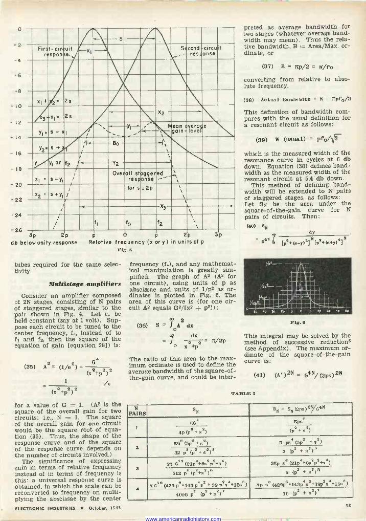
0
-2
-4
-6
-8
-IO
- 12
- 14
- 16
- 18
- 20
-22
- 24
-26
_.. -.._ s
First response..
-circuit _XI Second ,-- -circuit response
x1+ 2" 2s
3-x1= 2s -. X2
Yi' s - x I / `` ` Mean
1
overage gain- lever
Y I .: --
y2_ s+ - ¡ /
_
]\\ \
Bo
Y - Y1 or y2 I
i .
\ ! \
y2
XI = S - y1
/ i
/ Overall.staggered
response -\ x2 =
s+y1
/ /
/
tor s=2p \
\
/ X3 -- < \ /
/ fi f0
f2
\ \\
p ¿P db below unity response
p v p ¿p Relative frequency (x or y) in units of p
Fig. 5
tubes required for the same selec- tivity.
Multistage amplifiers
Consider an amplifier composed of 2N stages, consisting of N pairs of staggered stages, similar to the pair shown in Fig. 4. Let e, be held constant (say at 1 volt). Sup- pose each circuit to be tuned to the center frequency, f instead of to f1 and f2, then the square of the equation of gain [equation 28]) is:
4
(35) A2= (1/e2) _ (x2+p2)2
1
2 +p2) 2
for a value of G = 1. (A2 is the square of the overall gain for two circuits: i.e., N = 1. The square of the overall gain for one circuit would be the square root of equa- tion (35). Thus, the shape of the response curve and of the square of the response curve depends on the number of circuits involved.)
The significance of expressing gain in terms of relative frequency instead of in terms of frequency is this: a universal response curve is obtained, in which the scale can be reconverted to frequency on multi- plying the abscissae by the center ELECTRONIC INDUSTRIES October, 1e43
frequency (f,), and any mathemat- ical manipulation is greatly sim- plified. The graph of A2 (A2 for one circuit), using units of p as abscissae and units of 1/p2 as or- dinates is plotted in Fig. 6. The area of this curve is (for one cir- cuit A2 equals G2/[x2 -i- p2]) :
°D 2 (36) S =A dx
+p
dx 2 2 - It/2P
The ratio of this area to the max- imum ordinate is used to define the average bandwidth of the square -of - the -gain curve, and could be inter-
preted as average bandwidth for two stages (whatever average band- width may mean). Thus the rela- tive bandwidth, B = Area/Max. or- dinate, or
(37) B = ltp/2 = W/fo
converting from relative to abso- lute frequency.
(38) Actual Bandwidth = W = TCpf0/2
This definition of bandwidth com- pares with the usual definition for a resonant circuit as follows:
(39) W (usual) =
which is the measured width of the resonance curve in cycles at 6 db down. Equation (38) defines band- width as the measured width of the resonant circuit at 5.4 db down.
This method of defining band- width will be extended to N pairs of staggered stages, as follows: Let SN be the area under the square -of -the -gain curve for N pairs of circuits. Then: (40) 8N
G4N [Pº+ (e -y) 2] N [P2+ (+y)
2] N
dy
Fig. 6
This integral may be solved by the method of successive reductions (see Appendix). The maximum or- dinate of the square -of -the -gain curve is:
(41) (A, ) 2N = G4N/ (2ps) 2N
TABLE I
N PAIRS
SN BN = SN(2ps)2G4N
1
no 2
Tips Tips 2 2
4p (122 +s )
2 2 (P +s )
2 TiG (5p2+s2) Ti ps4(5p2 +s2)
32 ps(P2+s2)3 2 (P2 + s2)3
3 612
4 2 2 4 31C (21p +6s p +s )
8 4 2 2 3TCp s (21p +6s p +s4 )
512 p6(P2+s2)6 8 (P2 + s2)5
4 42 2
TC 658(429 p8 +143 p s + 39 p s 4 +15s
8 )
8 TCp s 6 4 2 2 4 8
(429p +143p s+39p s +15s )
4096 P7 (P2 + s2) 7 16 (P2 + s2)
93
www.americanradiohistory.com
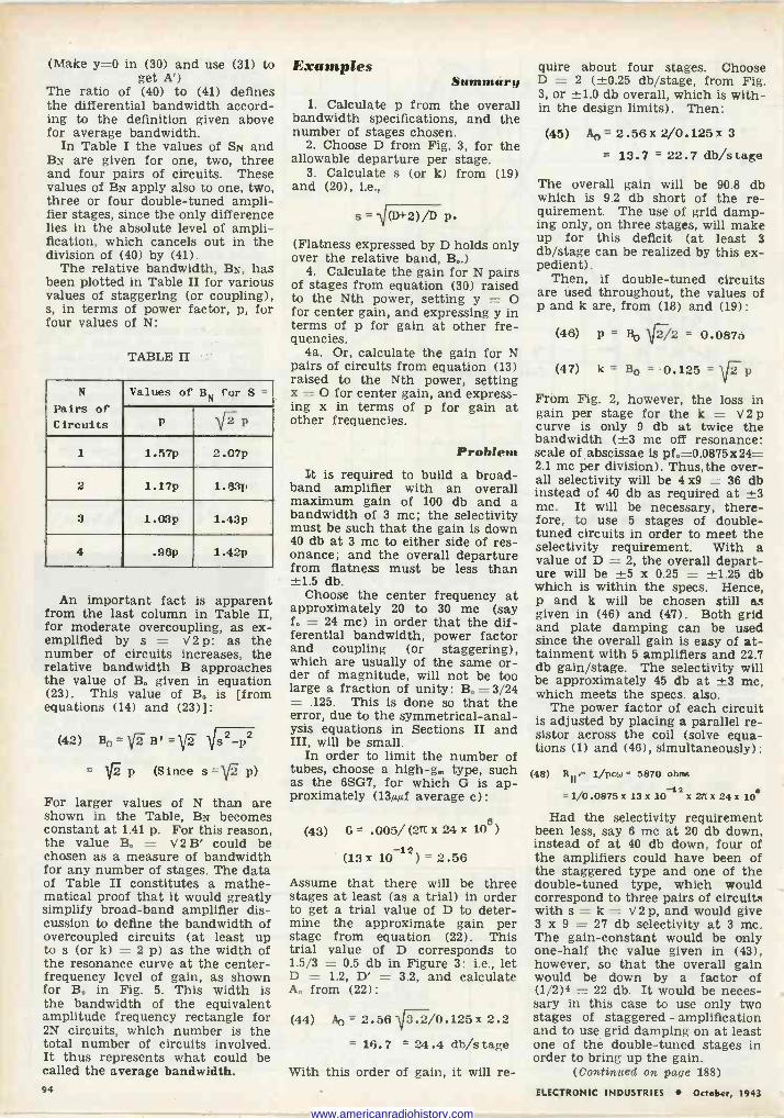
(Make y=0 in (30) and use (31) to get A')
The ratio of (40) to (41) defines the differential bandwidth accord- ing to the definition given above for average bandwidth.
In Table I the values of SN and BN are given for one, two, three and four pairs of circuits. These values of BN apply also to one, two, three or four double -tuned ampli- fier stages, since the only difference lies in the absolute level of ampli- fication, which cancels out in the division of (40) by (41).
The relative bandwidth, BN, has been plotted in Table II for various values of staggering (or coupling), s, in terms of power factor, p, for four values of N:
TABLE II
N
Pairs of Circuits
Values of BN for S =
p \p 1 1.57p 2.07p
2 1.17p 1.63p
3 1.03p 1.43p
4 .96p 1.42p
An important fact is apparent from the last column in Table II, for moderate overcoupling, as ex- emplified by s = V2 p: as the number of circuits increases, the relative bandwidth B approaches the value of B. given in equation (23). This value of B. is [from equations (14) and (23)]:
(42) Bo = v2 Bt =VT .'s2 -p2
= p (Since s = V" p)
For larger values of N than are shown in the Table, BN becomes constant at 1.41 p. For this reason, the value B. = V2 B' could be chosen as a measure of bandwidth for any number of stages. The data of Table II constitutes a mathe- matical proof that it would greatly simplify broad -band amplifier dis- cussion to define the bandwidth of overcoupled circuits (at least up to s (or k) = 2 p) as the width of the resonance curve at the center - frequency level of gain, as shown for B. in Fig. 5. This width is the bandwidth of the equivalent amplitude frequency rectangle for 2N circuits, which number is the total number of circuits involved. It thus represents what could be called the average bandwidth.
Examples Summary
1. Calculate p from the overall bandwidth specifications, and the number of stages chosen.
2. Choose D from Fig. 3, for the allowable departure per stage.
3. Calculate s (or k) from (19) and (20), i.e.,
s = "\RD+2)/D P (Flatness expressed by D holds only over the relative band, B..)
4. Calculate the gain for N pairs of stages from equation (30) raised to the Nth power, setting y = O for center gain, and expressing y in terms of p for gain at other fre- quencies.
4a. Or, calculate the gain for N pairs of circuits from equation (13) raised to the Nth power, setting x = O for center gain, and express- ing x in terms of p for gain at other frequencies.
Problem It is required to build a broad-
band amplifier with an overall maximum gain of 100 db and a bandwidth of 3 mc; the selectivity must be such that the gain is down 40 db at 3 mc to either side of res- onance; and the overall departure from flatness must be less than ±1.5 db.
Choose the center frequency at approximately 20 to 30 mc (say f. = 24 mc) in order that the dif- ferential bandwidth, power factor and coupling (or staggering), which are usually of the same or- der of magnitude, will not be too large a fraction of unity: B. = 3/24 = .125. This is done so that the error, due to the symmetrical -anal- ysis equations in Sections II and III, will be small.
In order to limit the number of tubes, choose a high -gm type, such as the 6SG7, for which G is ap- proximately (13µM average c):
(43) G = .005/ (27t x 24 x 106)
(13 x 10-12) = 2.56
Assume that there will be three stages at least (as a trial) in order to get a trial value of D to deter- mine the approximate gain per stage from equation (22). This trial value of D corresponds to 1.5/3 = 0.5 db in Figure 3: i.e., let D = 1.2, D' = 3.2, and calculate A. from (22):
(44) Ao = 2.56 3.2/0.125 x 2.2
= 16.7 = 24.4 db/s tage
With this order of gain, it will re-
quire about four stages. Choose D = 2 (±0.25 db/stage, from Fig. 3, or ±1.0 db overall, which is with- in the design limits). Then:
(45) = 2.56 x 2/0.125 x 3
= 13.7 = 22.7 db/stage
The overall gain will be 90.8 db which is 9.2 db short of the re- quirement. The use of grid damp- ing only, on three stages, will make up for this deficit (at least 3 db/stage can be realized by this ex- pedient).
Then, if double -tuned circuits are used throughout, the values of p and k are, from (18) and (19):
(46) p = B0 f2/2 = 0.0875
(47) k= Bo = 0.125 = 1 f 2 p
From Fig. 2, however, the loss in gain per stage for the k = V2 p curve is only 9 db at twice the bandwidth (±3 me off resonance: scale of abscissae is pf0=0.0875x24= 2.1 me per division) . Thus, the over- all selectivity will be 4x9 = 36 db instead of 40 db as required at ±3 mc. It will be necessary, there- fore, to use 5 stages of double - tuned circuits in order to meet the selectivity requirement. With a value of D = 2, the overall depart- ure will be ±5 x 0.25 = ±1.25 db which is within the specs. Hence, p and k will be chosen still as given in (46) and (47). Both grid and plate damping can be used since the overall gain is easy of at- tainment with 5 amplifiers and 22.7 db gain/stage. The selectivity will be approximately 45 db at ±3 mc, which meets the specs. also.
The power factor of each circuit is adjusted by placing a parallel re- sistor across the coil (solve equa- tions (1) and (46), simultaneously):
(48) R I I ` 1/pcW = 5870 ohms
=1/0.0875x 13x 10-12 X 21íx 24x 10
Had the selectivity requirement been less, say 6 mc at 20 db down, instead of at 40 db down, four of the amplifiers could have been of the staggered type and one of the double -tuned type, which would correspond to three pairs of circuits with s = k = V2 p, and would give 3 x 9 = 27 db selectivity at 3 mc. The gain -constant would be only one-half the value given in (43), however, so that the overall gain would be down by a factor of (1/2)4 = 22 db. It would be neces- sary in this case to use only two stages of staggered - amplification and to use grid damping on at least one of the double -tuned stages in order to bring up the gain.
(Continued on page 188)
94 ELECTRONIC INDUSTRIES October, 1943
www.americanradiohistory.com
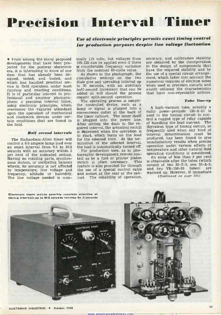
Precision Interval Tinier
From among the many proposed developments that have been pro- jected for the postwar electronic era, it is interesting to know of one item that has already been de- signed, tested, and tooled, and which has handled practical ser- vice in field operation under most rigorous and exacting conditions. It is of particular interest to pro- fessional and amateur photogra- phers: a precision interval timer, using electronic principles, which overcomes the vagaries attendant upon the operation of mechanical and clockwork devices under cer- tain conditions that are found in the field.
Half second intervals The Richardson -Allen timer will
control a 6.0 ampere lamp load over an exact interval from 0.5 to 30.5 seconds with an accuracy within 5 per cent of the indicated setting. Having no rotating parts, synchro- nous motors, or oscillating balance wheels, its accuracy is not affected by temperature, line voltage and frequency, altitude or humidity. The line voltage needed is nom -
Use of electronic principles permits exact timing control for production purposes despite line voltage fluctuation
inally 115 volts, but voltages from 105-125 can be applied even if there is considerable frequency variation from the nominal 60 -cycle value.
As shown in the photograph, the cumulative settings on the two dials give any operating interval up to 30 seconds, with an auxiliary half -second increment that can be added at will should the process require split-second operation.
The operating process is simple: the controlled device, such as a lamp or signal is plugged into a convenience outlet at the back of the timer cabinet. The timer itself is plugged into the power line. After setting the dials to the re- quired interval, the actuating switch is depressed when the operation is to start, which turns on the load for the selected time. At the ter- mination of the selected interval, the load is automatically turned off.
For production uses, as in pho- tographic development, remote con- trol as by a foot or printer platen switch is often necessary. This feature is also provided for through the use of a special control cable and socket at the rear of the cab- inet. The reliability of operation,
Electronic tinier makes possible accurate selection of timing intervals up to 30.5 seconds varying by .5 seconds
accuracy, and calibration stability are obtained by the incorporation in the design of components that have the required stability and by the use of a special circuit arrange- ment, which takes into account the numerous vagaries of electron tubes when used in precision circuits and avoids utilizing the characteristics that have non -repeatable actions.
Tube line-up
A high -vacuum tube, actually a radio power -pentode (35-A-5) is used in the timing circuit to con- trol a rugged type of relay capable of handling the load current. The thyratron type of timing circuit, so frequently used when any kind of interval determination must be produced, has been found to give unsatisfactory results when precise operation under various effects of temperature and other natural field operating conditions is considered.
An error of less than 5 per cent is obtainable after the tubes (which consist of two 35-Z-3, one 35-A-5, and two VR -150-30 tubes) are warmed up. However, if immediate
(Continued on page 184)
ELECTRONIC INDUSTRIES October, 1943 95
www.americanradiohistory.com
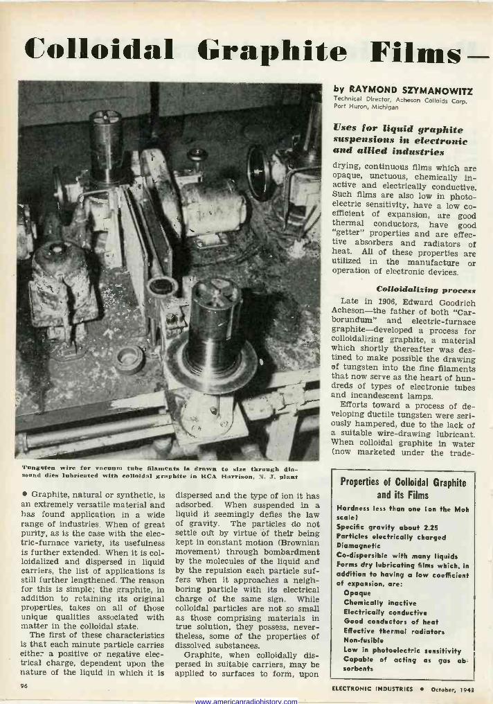
Colloidal Graphite Films
Tungsten wire for vacuum tube filaments is drawn to size through dia- mond dies lubricated with colloidal graphite in RCA Harrison, N. J. plant
Graphite, natural or synthetic, is an extremely versatile material and has found application in a wide range of industries. When of great purity, as is the case with the elec- tric -furnace variety, its usefulness is further extended. When it is col- loidalized and dispersed in liquid carriers, the list of applications is still further lengthened. The reason for this is simple; the graphite, in addition to retaining its original properties, takes on all of those unique qualities associated with matter in the colloidal state.
The first of these characteristics is that each minute particle carries either a positive or negative elec- trical charge, dependent upon the nature of the liquid in which it is
dispersed and the type of ion it has adsorbed. When suspended in a liquid it seemingly defies the law of gravity. The particles do not settle out by virtue of their being kept in constant motion (Brownian movement) through bombardment by the molecules of the liquid and by the repulsion each particle suf- fers when it approaches a neigh- boring particle with its electrical charge of the same sign. While colloidal particles are not so small as those comprising materials in true solution, they possess, never- theless, some of the properties of dissolved substances.
Graphite, when colloidally dis- persed in suitable carriers, may be applied to surfaces to form, upon
by RAYMOND SZYMANOWITZ Technical Director, Acheson Colloids Corp. Port Huron, Michigan
Uses for liquid graphite suspensions in electronic and allied industries drying, continuous films which are opaque, unctuous, chemically in- active and electrically conductive. Such films are also low in photo- electric sensitivity, have a low co- efficient of expansion, are good thermal conductors, have good "getter" properties and are effec- tive absorbers and radiators of heat. All of these properties are utilized in the manufacture or operation of electronic devices.
Colloidsfixing process Late in 1906, Edward Goodrich
Acheson-the father of both "Car- borundum" and electric -furnace graphite-developed a process for colloidalizing graphite, a material which shortly thereafter was des- tined to make possible the drawing of tungsten into the fine filaments that now serve as the heart of hun- dreds of types of electronic tubes and incandescent lamps.
Efforts toward a process of de- veloping ductile tungsten were seri- ously hampered, due to the lack of a suitable wire -drawing lubricant. When colloidal graphite in water (now marketed under the trade -
Properties of Colloidal Graphite
and its Films Hardness less than one (on the Moh scale) Specific gravity about 2.25 Particles electrically charged Diamagnetic Co -dispersible with many liquids Forms dry lubricating films which, in addition to having a low coefficient of expansion, are:
Opaque Chemically inactive Electrically conductive Good conductors of heat Effective thermal radiators Non -fusible Low in photoelectric sensitivity Capable of acting as gas ab- sorbents
96 ELECTRONIC INDUSTRIES October, 1943
www.americanradiohistory.com
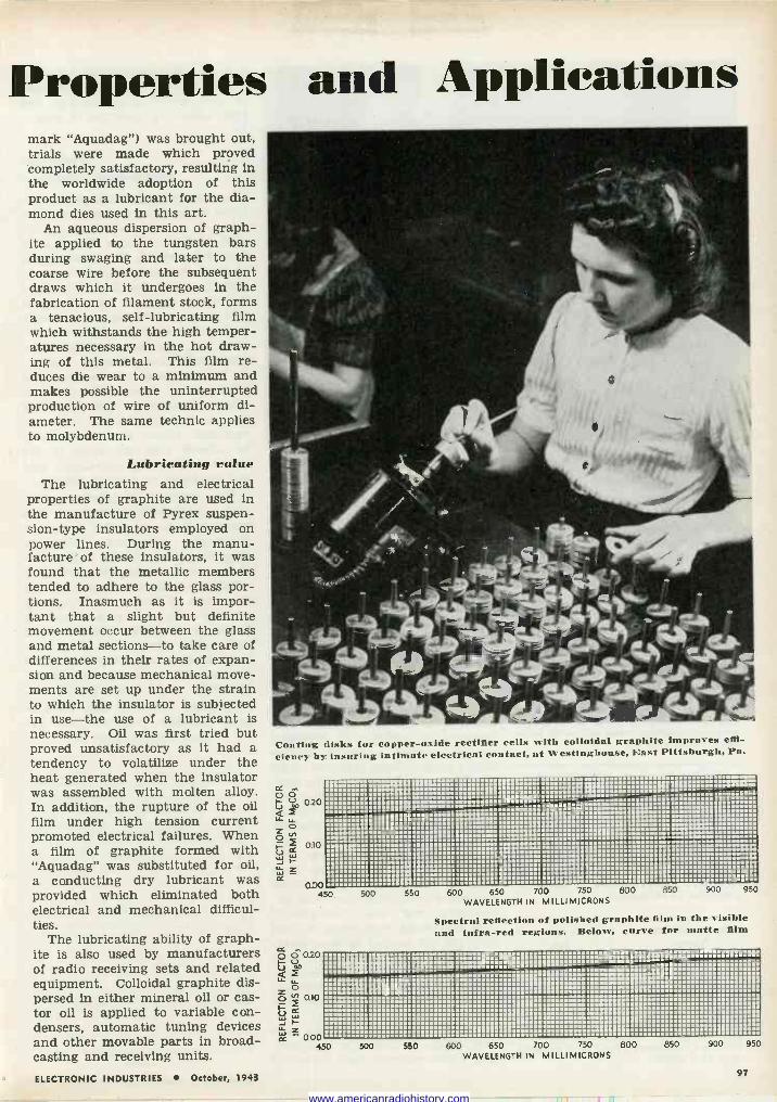
Properties and Applications mark "Aquadag") was brought out, trials were made which proved completely satisfactory, resulting in the worldwide adoption of this product as a lubricant for the dia- mond dies used in this art.
An aqueous dispersion of graph- ite applied to the tungsten bars during swaging and later to the coarse wire before the subsequent draws which it undergoes in the fabrication of filament stock, forms a tenacious, self-lubricating film which withstands the high temper- atures necessary in the hot draw- ing of this metal. This film re- duces die wear to a minimum and makes possible the uninterrupted production of wire of uniform di- ameter. The same technic applies to molybdenum.
Lubricating value The lubricating and electrical
properties of graphite are used in the manufacture of Pyrex suspen- sion -type insulators employed on power lines. During the manu- facture of these insulators, it was found that the metallic members tended to adhere to the glass por- tions. Inasmuch as it is impor- tant that a slight but definite movement occur between the glass and metal sections-to take care of differences in their rates of expan- sion and because mechanical move- ments are set up under the strain to which the insulator is subjected in use-the use of a lubricant is necessary. Oil was first tried but proved unsatisfactory as it had a tendency to volatilize under the heat generated when the insulator was assembled with molten alloy. In addition, the rupture of the oil film under high tension current promoted electrical failures. When a film of graphite formed with "Aquadag" was substituted for oil, a conducting dry lubricant was provided which eliminated both electrical and mechanical difficul- ties.
The lubricating ability of graph- ite is also used by manufacturers of radio receiving sets and related equipment. Colloidal graphite dis- persed in either mineral oil or cas- tor oil is applied to variable con- densers, automatic tuning devices and other movable parts in broad- casting and receiving units.
Coating disks for copper -oxide rectifier cells with colloidal graphite improves effi-
ciency by insuring intimate electrical contact, at Westinghouse, East Pittsburgh, Pa.
0.20
0.00 450 500 550 600 650 700 750 800 850 900 950
WAVELENGTH IN MILLIM)CRONS
Spectral reflection of polished graphite film in the visible and infra -red regions. Below, curve for matte film
p 030 áf LL
0 óo.00 W
z cc - 0.00
450 500 550 600 650 700 750 800 WAVELENGTH IN MILLIMICRONS
850 900 950
ELECTRONIC INDUSTRIES October, 1943 97
www.americanradiohistory.com
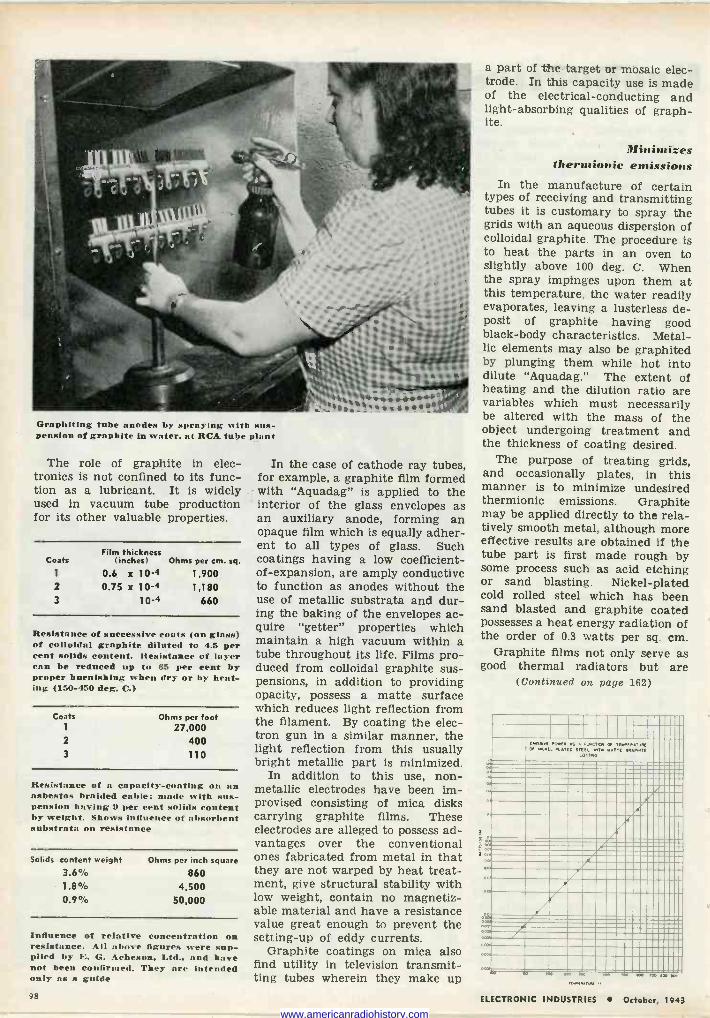
Graphiting tube auudes by spraying kith suS- pension of graphite in water, at RCA tube plant
The role of graphite in elec- tronics is not confined to its func- tion as a lubricant. It is widely used in vacuum tube production for its other valuable properties.
Film thickness Coats (inches) Ohms per cm. sq.
1 0.6 x 10⁻⁴ 1,900 2 0.75 x 10⁻⁴ 1,180 3 10-4 660
Resistance of successive coats (on glass) of colloidal graphite diluted to 4.5 per cent solids content. Resistance of layer can be reduced up to 65 per cent by proper burnishing when dry or by heat- ing (150-450 deg. C.)
Coats
2
3
Ohms per foot 27.000
400 110
Resistance of n capacity -coating on an asbestos braided cable; made with sus- pension having 9 per cent solids content by weight. Shows influence of absorbent substrata on resistance
Solids content weight 3.6% 1.8% 0.9%
Ohms per inch square
860 4,500
50,000
Influence of relative concentration on resistance. All above figures were sup- plied by E. G. Acheson. Ltd., and have not been confirmed. They are intended only as a guide
In the case of cathode ray tubes, for example, a graphite film formed with "Aquadag" is applied to the interior of the glass envelopes as an auxiliary anode, forming an opaque film which is equally adher- ent to all types of glass. Such coatings having a low coefficient - of -expansion, are amply conductive to function as anodes without the use of metallic substrata and dur- ing the baking of the envelopes ac- quire "getter" properties which maintain a high vacuum within a tube throughout its life. Films pro- duced from colloidal graphite sus- pensions, in addition to providing opacity, possess a matte surface which reduces light reflection from the filament. By coating the elec- tron gun in a similar manner, the light reflection from this usually bright metallic part is minimized.
In addition to this use, non- metallic electrodes have been im- provised consisting of mica disks carrying graphite films. These electrodes are alleged to possess ad- vantages over the conventional ones fabricated from metal in that they are not warped by heat treat- ment, give structural stability with low weight, contain no magnetiz- able material and have a resistance value great enough to prevent the setting -up of eddy currents.
Graphite coatings on mica also find utility in television transmit- ting tubes wherein they make up
a part of the target or mosaic elec- trode. In this capacity use is made of the electrical -conducting and light -absorbing qualities of graph- ite.
!Iinimizes thermionic emissions
In the manufacture of certain types of receiving and transmitting tubes it is customary to spray the grids with an aqueous dispersion of colloidal graphite. The procedure is to heat the parts in an oven to slightly above 100 deg. C. When the spray impinges upon them at this temperature, the water readily evaporates, leaving a lusterless de- posit of graphite having good black -body characteristics. Metal- lic elements may also be graphited by plunging them while hot into dilute "Aquadag." The extent of heating and the dilution ratio are variables which must necessarily be altered with the mass of the object undergoing treatment and the thickness of coating desired.
The purpose of treating grids, and occasionally plates, in this manner is to minimize undesired thermionic emissions. Graphite may be applied directly to the rela- tively smooth metal, although more effective results are obtained if the tube part is first made rough by some process such as acid etching or sand blasting. Nickel -plated cold rolled steel which has been sand blasted and graphite coated possesses a heat energy radiation of the order of 0.3 watts per sq. cm.
Graphite films not only serve as good thermal radiators but are
(Continued on page 162)
MEIBiiiiiñüiiiiiii qx EVEI,.TVÆ
IIIIII TN t E ER1PaTE M CICC 11: MMM .. M.. .. in /.ii111 -fii'ti ..111111111
1111illlllllll
omen PONES AS A TWO Of !O L PLATED STEEL
C01í
1.11.11 ..-- MM.!JMMIMIM M M I1 IMPIZIiii111111
MIIMIMMIAIMIIIIMMIA1111111
11i111ÌÌÌÌIÌÌIÌÌIÌÌ ----...... IM .. . ái::i MM aa 811111 IIIIIIIIII 98 ELECTRONIC INDUSTRIES October, 1943
www.americanradiohistory.com
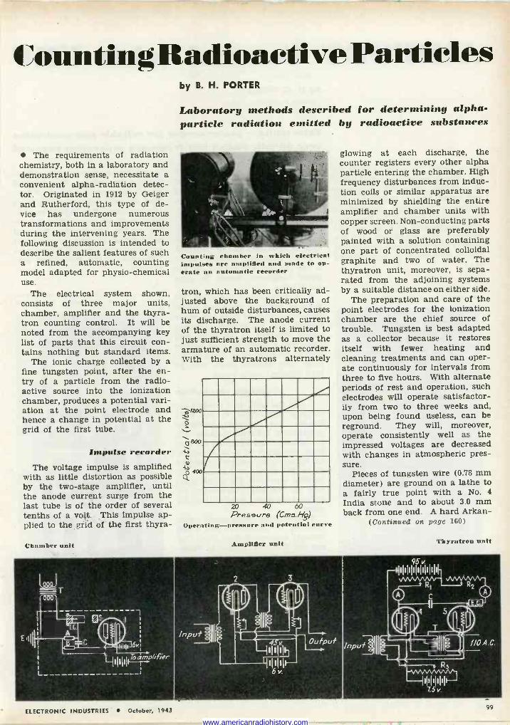
Counting Radioactive Particles
The requirements of radiation chemistry, both in a laboratory and demonstration sense, necessitate a convenient alpha -radiation detec- tor. Originated in 1912 by Geiger and Rutherford, this type of de- vice has undergone numerous transformations and improvements during the intervening years. The following discussion is intended to describe the salient features of such a refined, automatic, counting model adapted for physio-chemical use.
The electrical system shown, consists of three major units, chamber, amplifier and the thyra- tron counting control. It will be noted from the accompanying key list of parts that this circuit con- tains nothing but standard items.
The ionic charge collected by a fine tungsten point, after the en- try of a particle from the radio- active source into the ionization chamber, produces a potential vari- ation at the point electrode and hence a change in potential at the grid of the first tube.
Impulse recorder The voltage impulse is amplified
with as little distortion as possible by the two -stage amplifier, until the anode current surge from the last tube is of the order of several tenths of a volt. This impulse ap- plied to the grid of the first thyra-
Chamber unit
by B. H. PORTER
Laboratory methods described for determining alpha - particle radiation emitted by radioactive substances
Counting chamber in which electrical impulses are amplified and made to op- erate an automatic recorder
tron, which has been critically ad- justed above the background of hum of outside disturbances, causes its discharge. The anode current of the thyratron itself is limited to just sufficient strength to move the armature of an automatic recorder. With the thyratrons alternately
20 40 60 Presearre (Cms.H8,)
Operating-pressure and potential curve
Amplifier unit
glowing at each discharge, the counter registers every other alpha particle entering the chamber. High frequency disturbances from induc- tion coils or similar apparatus are minimized by shielding the entire amplifier and chamber units with copper screen. Non -conducting parts of wood or glass are preferably painted with a solution containing one part of concentrated colloidal graphite and two of water. The thyratron unit, moreover, is sepa- rated from the adjoining systems by a suitable distance on either side.
The preparation and care of the point electrodes for the ionization chamber are the chief source of trouble. Tungsten is best adapted as a collector because it restores itself with fewer heating and cleaning treatments and can oper- ate continuously for intervals from three to five hours. With alternate periods of rest and operation, such electrodes will operate satisfactor- ily from two to three weeks and, upon being found useless, can be reground. They will, moreover, operate consistently well as the impressed voltages are decreased with changes in atmospheric pres- sure.
Pieces of tungsten wire (0.78 mm diameter) are ground on a lathe to a fairly true point with a No. 4
India stone and to about 3.0 mm back from one end. A hard Arkan-
(Continued on page 160)
Thyratron unit
Input
0 R
EC
T SO -1 I IIIQ )
' , R
7.S v.
I/O A. C.
ELECTRONIC INDUSTRIES October, 1943 99
www.americanradiohistory.com
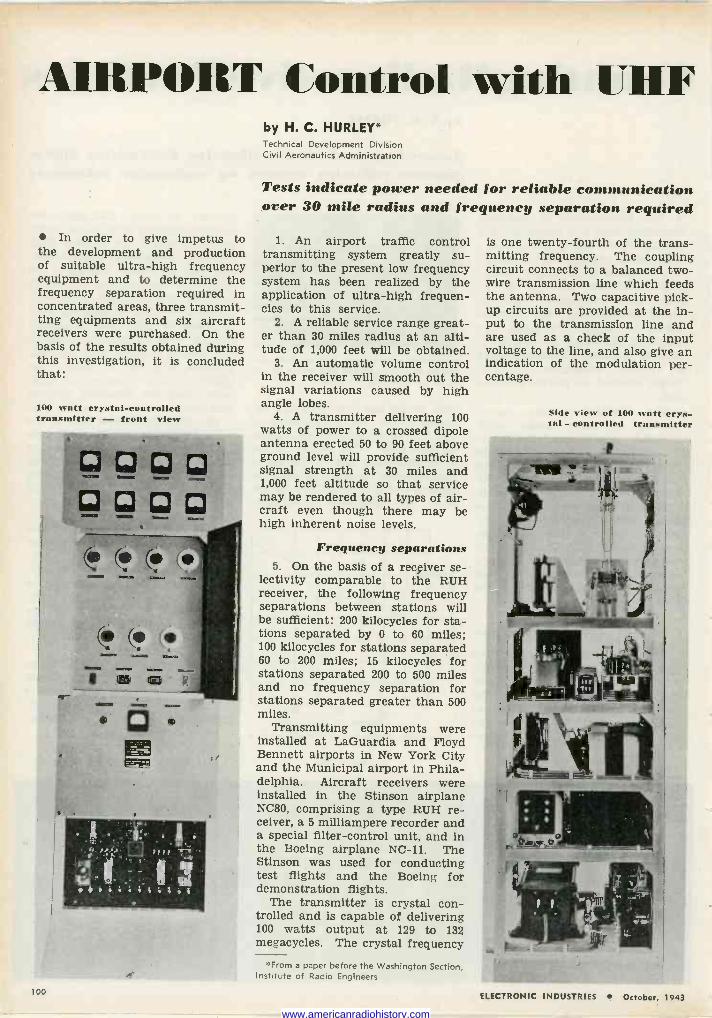
AIRPORT Control with UHF
In order to give impetus to the development and production of suitable ultra -high frequency equipment and to determine the frequency separation required in concentrated areas, three transmit- ting equipments and six aircraft receivers were purchased. On the basis of the results obtained during this investigation, it is concluded that:
100 watt crystal -controlled transmitter - front view
® ® Q 10 GI GI p
by H. C. HURLEY* Technical Development Division Civil Aeronautics Administration
Tests indicate power needed for reliable communication over 30 mile radius and frequency separation required
1. An airport traffic control transmitting system greatly su- perior to the present low frequency system has been realized by the application of ultra -high frequen- cies to this service.
2. A reliable service range great- er than 30 miles radius at an alti- tude of 1,000 feet will be obtained.
3. An automatic volume control in the receiver will smooth out the signal variations caused by high angle lobes.
4. A transmitter delivering 100 watts of power to a crossed dipole antenna erected 50 to 90 feet above ground level will provide sufficient signal strength at 30 miles and 1,000 feet altitude so that service may be rendered to all types of air- craft even though there may be high inherent noise levels.
Frequency separations 5. On the basis of a recçiver se-
lectivity comparable to the RUH receiver, the following frequency separations between stations will be sufficient: 200 kilocycles for sta- tions separated by 0 to 60 miles; 100 kilocycles for stations separated 60 to 200 miles; 15 kilocycles for stations separated 200 to 500 miles and no frequency separation for stations separated greater than 500 miles.
Transmitting equipments were installed at LaGuardia and Floyd Bennett airports in New York City and the Municipal airport in Phila- delphia. Aircraft receivers were installed in the Stinson airplane NC80, comprising a type RUH re- ceiver, a 5 milliampere recorder and a special filter -control unit, and in the Boeing airplane NC -11. The Stinson was used for conducting test flights and the Boeing for demonstration flights.
The transmitter is crystal con- trolled and is capable of delivering 100 watts output at 129 to 132 megacycles. The crystal frequency
''From a paper before the Washington Section, Institute of Radio Engineers
is one twenty-fourth of the trans- mitting frequency. The coupling circuit connects to a balanced two - wire transmission line which feeds the antenna. Two capacitive pick- up circuits are provided at the in- put to the transmission line and are used as a check of the input voltage to the line, and also give an indication of the modulation per- centage.
Side view of 100 watt crys- tal - controlled transmitter
100 ELECTRONIC INDUSTRIES October, 1943
www.americanradiohistory.com
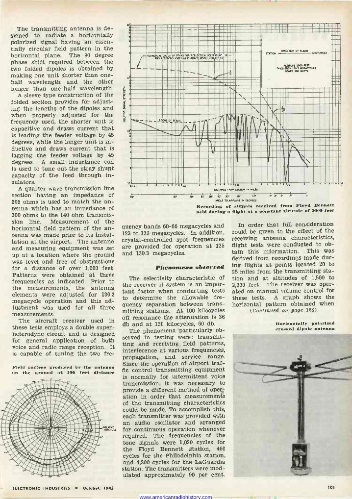
The transmitting antenna is de- signed to radiate a horizontally polarized signal having an essen- tially circular field pattern in the horizontal plane. The 90 degree phase shift required between the two folded dipoles is obtained by making one unit shorter than one- half wavelength and the other longer than one-half wavelength.
A sleeve type construction of the folded section provides for adjust- ing the lengths of the dipoles and when properly adjusted for the frequency used, the shorter unit is capacitive and draws current that is leading the feeder voltage by 45 degrees, while the longer unit is in- ductive and draws current that is lagging the feeder voltage by 45 degrees. A small inductance coil is used to tune out the stray shunt capacity of the feed through in- sulators.
A quarter wave transmission line section having an impedance of 205 ohms is used to match the an- tenna which has an impedance of 300 ohms to the 140 ohm transmis- sion line. Measurement of the horizontal field pattern of the an- tenna was made prior to its instal- lation at the airport. The antenna and measuring equipment was set up at a location where the ground was level and free of obstructions for a distance of over 1,000 feet. Patterns were obtained at three frequencies as indicated. Prior to the measurements, the antenna elements were adjusted for 130.3 megacycle operation and this ad- justment was used for all three measurements.
The aircraft receiver used in these tests employs a double super- heterodyne circuit and is designed for general application of both voice and radio range reception. It is capable of tuning the two fre-
Field pattern, produced by the antenna on the ground nt 100 feet distance
ÌTIVE ATaUE
E h
Ea
THEORETICALLOCUS 0
PEAKS FOR REFLECTION COEFFICIENT N) = RECEPONGNOTENVA CHARACTERISTIC NEGLECTED
.L.
\
ED 0.01
r
1 . T ..QE
:r
ì'
-
DIRECTION OF FLIGHT STAi M SOUTHWEST
PURSE 2000 FEET F30.3 MEG.CYCEES I00 WATTS
a
3 . 1 T ..L.o , . . . le, DISTANCE FROM STATION IN MILES
1 I I I 1 11 I 4
7 EO W KP se 2e w S . r r 1
ANGLE TO AIRPLANE IN DEGREES
Recording of signals received from Floyd Bennett field during a flight at a constant altitude of 2000 feet
quency bands 60-66 megacycles and 123 to 132 megacycles. In addition, crystal -controlled spot frequencies are provided for operation at 125
and 130.3 megacycles.
Phenomena observed
The selectivity characteristic of the receiver if system is an impor- tant factor when conducting tests to determine the allowable fre- quency separation between trans- mitting stations. At 100 kilocycles off resonance the attenuation is 36 db and at 150 kilocycles, 60 db.
The phenomena particularly ob- served in testing were: transmit- ting and receiving field patterns, interference at various frequencies, propagation, and service range. Since the operation of airport traf- fic control transmitting equipment is normally for intermittent voice transmission, it was necessary to provide a different method of operr ation in order that measurements of the transmitting characteristics could be made. To accomplish this, each transmitter was provided with an audio oscillator and arranged for continuous operation whenever required. The frequencies of the tone signals were 1,020 cycles for the Floyd Bennett station, 460 cycles for the Philadelphia station, and 4,300 cycles for the LaGuardia station. The transmitters were mod- ulated approximately 90 per cent.
. . Rice
In order that full consideration could be given to the effect of the receiving antenna characteristics, flight tests were conducted to ob- tain this information. This was derived from recordings made dur- ing flights at points located 20 to 25 miles from the transmitting sta- tion and at altitudes of 1,500 to 2,000 feet. The receiver was oper- ated on manual volume control for these tests. A graph shows the horizontal pattern obtained when
(Continued on page 168)
Horizontally polarized crossed dipole antenna
ELECTRONIC INDUSTRIES October, 1943
.
s
101
www.americanradiohistory.com
WHEN ENGINEER IS BOSS
DR. RAY H. MANSON
The management of many man- ufacturing plants has, in recent years, been turned over to engi- neering -trained men. The main reason for this is that the major- ity of management problems in these institutions are technical in nature. This is particularly true of the electrical and communica- tions industries, in which manu- factured products, from their in- ception to their end use, are of a highly technical nature.
For example, in the radio indus- try, we find engineers handling many problems, including the mak- ing of field surveys on product re- quirements, translating these sur- veys into product designs, super- vising the manufacturing of the product, handling the product quality control, instructing the sales and advertising departments on the product features and the product usefulness, supervising field servicing of the product and mak- ing studies of cost and profit pos- sibilities of the manufactured prod- uct, as well as proposed new prod- ucts.
Big difference There is a big step, however,
from knowing all about a product, to taking over the operating man- agement of a business of making and marketing a product. To man- age such a business suceessfully, the technically trained executive
by DR. RAY H. MANSON Vice -President and General Manager Stromberg -Carlson Co.
Row the engineering -trained executive can best tackle management thinking and action
must learn to handle the overall operations of the business from a broad -gage viewpoint and to do this with efficiency and dispatch.
Forget details To most engineers, who, from the
nature of their training, are steeped in the handling of details, this is a very difficult assignment. It is imperative that the engineer- ing -trained executive have a clear- cut picture of all of the operations of the business and not be dis- tracted or blinded by a maze of de- tail; in other words, he must learn to see and appreciate the beauties of the forest, rather than that of the individual trees.
This means the proper assigning of work to others, in order that the necessary details will be handled promptly and correctly and that there be complete coordination of effort to the common end of mak- ing the desired quality of product, at the time scheduled and with a profitable return to the owners of the business.
Outside contacts Besides handling internal prob-
lems of the business, the engineer- ing -trained executive must look for much outside help, such as can be obtained from memberships in national, manufacturing and trade
SEVEN REMINDERS
for the
ENGINEERING EXECUTIVE
Get away from needless details
Delegate authority to others
Obtain organization team work
Set performance schedules Get work done right, and
on time Make a reasonable profit Plan adequately for future
organizations. It is not enough to confine these outside contacts to the particular type of business im- mediately of interest, as the study of other industries often provides ideas which can be used to advan- tage.
In addition to running the in- ternal affairs of the business, the engineering -trained executive will find it advisable and, in many cases, necessary to do an intelli- gent job of reporting on internal operations of the company to di- rectors, stockholders and to an in- terested public.
Delegate authority All of this can be summed up
briefly in the statement that the engineering -trained executive must get away from needless details, delegate necessary authority to others, obtain organization team- work, set reasonable performance schedules, get work done right and on time, plan adequately for the future and, at all times, make a reasonable profit in the overall operations of the business.
About Dr. Manson Dr. Manson has been continu-
ously engaged in the communica- tions business since graduation from the University of Maine in 1898, first with the Western Electric Co., Chicago, then with the Kellogg Switchboard & Supply Co., also of Chicago, later with the Dean Elec- tric Co. and its successor, the Gar - ford Mfg. Co., both of Elyria, Ohio, and since 1916, with the Stromberg - Carlson Co., Rochester, N. Y.
In Stromberg -Carlson, he first held the position of chief engineer, later becoming a director and vice- president in charge of engineering and research. About three years ago he was made general manager of all Stromberg -Carlson opera- tions, retaining his official position as a director and vice-president.
In 1931 Dr. Manson served as president of the Institute of Radio Engineers and, in 1933, he was given the degree of Doctor of En- gineering by the University of Maine. Over 110 United States patents on communications and kindred subjects have been issued in his name.
102 ELECTRONIC INDUSTRIES October, 1943
www.americanradiohistory.com
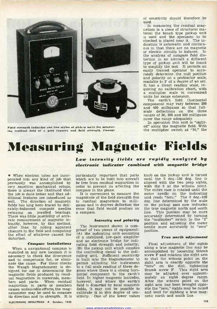
Field strength indicator and two styles of pickup units for measur- ing residual field of a part (upper) and field strength (lower)
of sensitivity should therefore be used.
In measuring the residual mag- netism in a piece of structural ma- terial the bench type pickup unit is used and the specimen to be checked is placed near it. The in- dicating is automatic and continu- ous in that there are no magnetic or electric circuits to balance. In the analysis of compass field dis- tortion in an aircraft a different type of pickup unit will be found to simplify the test. It permits an easily trained operator to accu- rately determine the null position and polarity on a protractor scale, readable to 3' of a degree of an arc. It has a direct reading scale, re- quiring no calibration chart, with a multiplier scale in convenient units for range extension.
The earth's field (horizontal component) may vary between 100 and 400 milligauss so that full- scale deflections on the three ranges of 30, 300 and 900 milligauss cover the range adequately.
In operation this unit is "sight- ed" along the magnetic field. With the multiplier switch at "10," the
Measuring Magnetic Fields
When electron tubes are incor- porated into any kind of job that previously was accomplished by very sensitive mechanical setups, there is always the likelihood that the job is done better and that ad- ditional features are introduced as well. The direction of magnetic fields has long been traced by deli- cately -balanced compass needles swinging on jewelled bearings. There was little possibility of accu- rate measurement of magnetic in- tensity, however, by this method, other than by noting apparent changes in the field and computing the effect of whatever caused the distortion.
Compass installations When a navigational compass is
installed in any new location it is necessary to check the divergence and to compensate for, or elimi- nate the cause. For these checks the Waugh Magnetometer is de- signed for use in determining the magnetic fields produced by resid- ual magnetism in materials, mem- bers and parts. When residual magnetism in parts or members causes undesirable effects, the mag- netometer may be used to measure its direction and its strength. It is
Low intensity fields are rapidly analyzed by electronic indicator combined with magnetic bridge
particularly important that parts which are to be built into aircraft be free from residual magnetism in order to prevent its affecting the compass in the plane.
It is convenient to measure the magnitude of the field strength due to residual magnetism in milli - gauss and in degrees deflection the error that field would produce on a compass.
Intensity and polarity The instrument shown is com-
prised of two pieces of equipment: (A) the indicating unit consisting of a stabilized, low -gain amplifier and an electronic bridge for indi- cating field strength and polarity; (B) the pickup unit which supplies the controlling signal to the indi- cating unit. Sufficient sensitivity is built into the Magnetometer to permit adjusting the instrument to a full scale reading of three de- grees where there is a strong hori- zontal component to the earth's field. In higher magnetic latitudes, however, and where the earth's field is distorted by local magnetic fields, it may not be possible to calibrate it to this degree of sen- sitivity. One of the lower values
knob on the pickup unit is turned until the 0 deg. -180 deg. line is aligned with the two peep sights, with the 0 at the witness point. The entire case is rotated until the meter needle on the indicating unit reads "zero." The 0 deg. -180 deg. line determined by the scale on the pickup unit now indicates the true magnetic north and south line. This position may be more accurately determined by turning the "multiplier" switch to the "I" position and adjusting the meter needle more accurately to "zero" position.
True north adjustment Final adjustment of the sights
along a true magnetic line may be accomplished by loosening thumb screw F and rotating the sight arm so that the witness point on the sight arm is exactly opposite the "zero" on the dial, tightening thumb screw F. This sight arm may be adjusted over approxi- mately an eight degree range. After the witness point on the sight arm has been brought oppo- site the "zero," sights may be raised and used for sighting a true mag- netic north and south line.
ELECTRONIC INDUSTRIES October, 1943 103
www.americanradiohistory.com
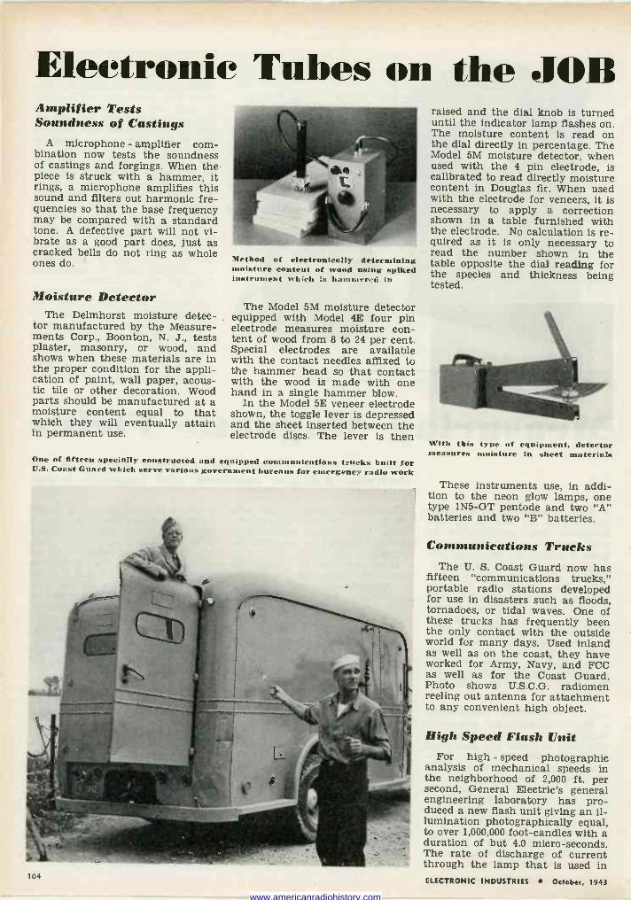
Electronic Tubes on the JOB Amplifier Tests Soundness of Castings
A microphone - amplifier com- bination now tests the soundness of castings and forgings. When the piece is struck with a hammer, it rings, a microphone amplifies this sound and filters out harmonic fre- quencies so that the base frequency may be compared with a standard tone. A defective part will not vi- brate as a good part does, just as cracked bells do not ring as whole ones do.
Moisture Detector The Delmhorst moisture detec-
tor manufactured by the Measure- ments Corp., Boonton, N. J., tests plaster, masonry, or wood, and shows when these materials are in the proper condition for the appli- cation of paint, wall paper, acous- tic tile or other decoration. Wood parts should be manufactured at a moisture content equal to that which they will eventually attain in permanent use.
Method of electronically determining moisture content of wood using spiked instrument whieh is hunt aro(i in
The Model 5M moisture detector equipped with Model 4E four pin electrode measures moisture con- tent of wood from 8 to 24 per cent. Special electrodes are available with the contact needles affixed to the hammer head so that contact with the wood is made with one hand in a single hammer blow.
In the Model 5E veneer electrode shown, the toggle lever is depressed and the sheet inserted between the electrode discs. The lever is then
One of fifteen specially constructed and equipped communications trucks built for U.S. Coast Guard which serve various government bureaus for emergency radio work
104
raised and the dial knob is turned until the indicator lamp flashes on. The moisture content is read on the dial directly in percentage. The Model 5M moisture detector, when used with the 4 pin electrode, is calibrated to read directly moisture content in Douglas fir. When used with the electrode for veneers, it is necessary to apply a correction shown in a table furnished with the electrode. No calculation is re- quired as it is only necessary to read the number shown in the table opposite the dial reading for the species and thickness being tested.
With this type of equipment, detector measures moisture in sheet materials
These instruments use, in addi- tion to the neon glow lamps, one type 1N5 -GT pentode and two "A" batteries and two "B" batteries.
Communications Trucks The U. S. Coast Guard now has
fifteen "communications trucks," portable radio stations developed for use in disasters such as floods, tornadoes, or tidal waves. One of these trucks has frequently been the only contact with the outside world for many days. Used inland as well as on the coast, they have worked for Army, Navy, and FCC as well as for the Coast Guard. Photo shows U.S.C.G. radiomen reeling out antenna for attachment to any convenient high object.
High Speed Flash Unit For high - speed photographic
analysis of mechanical speeds in the neighborhood of 2,000 ft. per second, General Electric's general engineering laboratory has pro- duced a new flash unit giving an il- lumination photographically equal, to over 1,000,000 foot-candles with a duration of but 4.0 micro -seconds. The rate of discharge of current through the lamp that is used in ELECTRONIC INDUSTRIES October, 1943
www.americanradiohistory.com
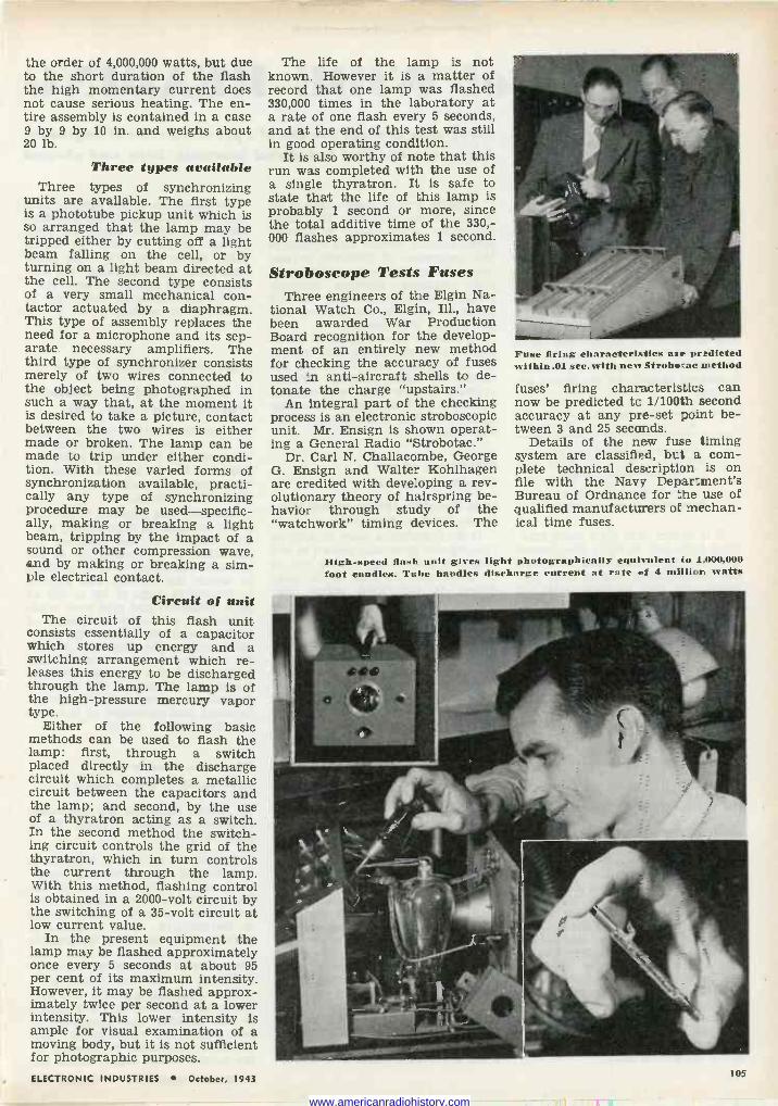
the order of 4,000,000 watts, but due to the short duration of the flash the high momentary current does not cause serious heating. The en- tire assembly is contained in a case 9 by 9 by 10 in. and weighs about 20 lb.
Three types available Three types of synchronizing
units are available. The first type is a phototube pickup unit which is so arranged that the lamp may be tripped either by cutting off a light beam falling on the cell, or by turning on a light beam directed at the cell. The second type consists of a very small mechanical con- tactor actuated by a diaphragm. This type of assembly replaces the need for a microphone and its sep- arate necessary amplifiers. The third type of synchronizer consists merely of two wires connected to the object being photographed in such a way that, at the moment it is desired to take a picture, contact between the two wires is either made or broken. The lamp can be made to trip under either condi- tion. With these varied forms of synchronization available, practi- cally any type of synchronizing procedure may be used-specific- ally, making or breaking a light beam, tripping by the impact of a sound or other compression wave, and by making or breaking a sim- ple electrical contact.
Circuit of unit The circuit of this flash unit
consists essentially of a capacitor which stores up energy and a switching arrangement which re- leases this energy to be discharged through the lamp. The lamp is of the high-pressure mercury vapor type.
Either of the following basic methods can be used to flash the lamp: first, through a switch placed directly in the discharge circuit which completes a metallic circuit between the capacitors and the lamp; and second, by the use of a thyratron acting as a switch. In the second method the switch- ing circuit controls the grid of the thyratron, which in turn controls the current through the lamp. With this method, flashing control is obtained in a 2000 -volt circuit by the switching of a 35 -volt circuit at low current value.
In the present equipment the lamp may be flashed approximately once every 5 seconds at about 95 per cent of its maximum intensity. However, it may be flashed approx- imately twice per second at a lower intensity. This lower intensity is ample for visual examination of a moving body, but it is not sufficient for photographic purposes.
The life of the lamp is not known. However it is a matter of record that one lamp was flashed 330,000 times in the laboratory at a rate of one flash every 5 seconds, and at the end of this test was still in good operating condition.
It is also worthy of note that this run was completed with the use of a single thyratron. It is safe to state that the life of this lamp is probably 1 second or more, since the total additive time of the 330,- 000 flashes approximates 1 second.
Stroboscope Tests Fuses Three engineers of the Elgin Na-
tional Watch Co., Elgin, Ill., have been awarded War Production Board recognition for the develop- ment of an entirely new method for checking the accuracy of fuses used :n anti-aircraft shells to de- tonate the charge "upstairs."
An integral part of the checking process is an electronic stroboscopic unit. Mr. Ensign is shown operat- ing a General Radio "Strobotac."
Dr. Carl N. Challacombe, George G. Ensign and Walter Kohlhagen are credited with developing a rev- olutionary theory of hairspring be- havior through study of the "watchwork" timing devices. The
Fuse firing characteristics are predicted within .01 sec. with new Strobetac method
fuses' firing characteristics can now be predicted to 1/100th second accuracy at any pre-set point be- tween 3 and 25 seconds.
Details of the new fuse timing system are classified, but a com- plete technical description is on file with the Navy Department's Bureau of Ordnance for the use of qualified manufacturers of mechan- ical time fuses.
High-speed flash unit gives light photographically equivalent to 1..000,000 foot candles. Tube handles discharge current at rate 1 4 million watts
ELECTRONIC INDUSTRIES October, 1943
1 Il
105
www.americanradiohistory.com
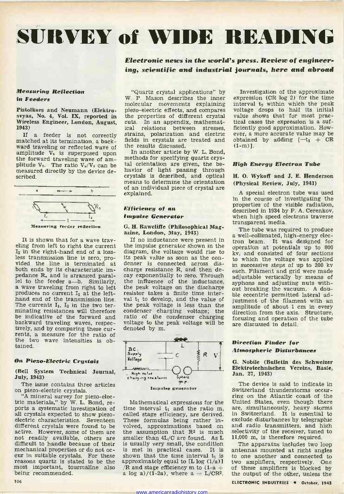
SURVEY of WIDE R
Measuring Reflection in Feeders Pistolkors and Neumann (Elektro- svyaz, No. 4, Vol. IX, reported in Wireless Engineer, London, August, 1943)
If a feeder is not correctly matched at its termination, a back- ward traveling or reflected wave of amplitude V. is superposed upon the forward traveling wave of am- plitude Vr. The ratio Vb/Vr can be measured directly by the device de- scribed.
a a - b
N w\
1
Measuring feeder reflection
It is shown that for a wave trav- eling from left to right the current I2 in the right-hand end of a loss - less transmission line is zero, pro- vided the line is terminated at both ends by its characteristic im- pedance R. and is arranged paral- lel to the feeder a-b. Similarly, a wave traveling from right to left produces no current I1 at the lef t - hand end of the transmission line. The currents II, I2 in the two ter- minating resistances will therefore be indicative of the forward and backward traveling waves, respec- tively, and by comparing these cur- rents, a measure for the ratio of the two wave intensities is ob- tained.
On Piezo-Electric Crystals (Bell System Technical Journal, July, 1943)
The issue contains three articles on piezo-electric crystals.
"A mineral survey for piezo-elec- tric materials," by W. L. Bond, re- ports a systematic investigation of all crystals expected to show piezo- electric characteristics. Seventeen different crystals were found to be active. However, some of them are not readily available, others are difficult to handle because of their mechanical properties or do not oc- cur in suitable crystals. For these reasons quartz is stated to be the most important, tourmaline also being recommended. 106
Electronic news in the world's press. Review of engineer- ing, scientific and industrial journals, here and abroad
"Quartz crystal applications" by W. P. Mason describes the inner molecular movements explaining piezo-electric effects, and compares the properties of different crystal cuts. In an appendix, mathemat- ical relations between stresses, strains, polarization and electric fields in crystals are treated and the results discussed.
In another article by W. L. Bond, methods for specifying quartz crys- tal orientation are given, the be- havior of light passing through crystals is described, and optical means to determine the orientation of an individual piece of crystal are explained.
Efficiency of an Impulse Generator G. H. Rawcliffe (Philosophical Mag- azine, London, May, 1943)
If no inductance were present in the impulse generator shown in the diagram, the voltage would rise to its peak value as soon as the con- denser is connected across dis- charge resistance R, and then de- cay exponentially to zero. Through the influence of the inductance, the peak voltage on the discharge resistor takes a finite time inter- val t1 to develop, and the value of the peak voltage is less than the condenser charging voltage; the ratio of the condenser charging voltage to the peak voltage will be denoted by m.
nc. Vol raye
V
, N.yh rol.,r chs,".n3 res. s to. nCt S phe -e
9S -p Impulse generator
Mathematical expressions for the time interval t1 and the ratio m, called stage efficiency, are derived. These formulas being rather in- volved, approximations based on the assumption that R2 is much smaller than 4L/C are found. As L is usually very small, the condition is met in practical cases. It is shown that the time interval t1 is approximately equal to [L log (1/a)l /R and stage efficiency m to (1-a + a log a)/(1 -2a), where a = L/CR2.
Investigation of the approximate expression (CR log 2) for the time interval t2 within which the peak voltage drops to half its initial value shows that for most prac- tical cases the expression is a suf- ficiently good approximation. How- ever, a more accurate value may be obtained by adding [-t1 + CR (1-m) ].
High Energy Electron Tube
H. O. Wykoff and J. E. Henderson (Physical Review, July, 1943)
A special electron tube was used in the course of investigating the properties of the visible radiation, described in 1934 by P. A. Cerenkov, when high speed electrons traverse transparent media.
The tube was required to produce a well -collimated, high-energy elec- tron beam. It was designed for operation at potentials up to 800 kv, and consisted of four sections to which the voltage was applied in successive steps of up to 200 kv each. Filament and grid were made adjustable vertically by means of syphons and adjusting nuts with- out breaking the vacuum. A dou- ble eccentric permitted lateral ad- justment of the filament with an amplitude of about 1 cm in every direction from the axis. Structure, focusing and operation of the tube are discussed in detail.
Direction Finder for Atmospheric Disturbances
G. Nobile (Bulletin des Schweizer Elektrotechnischen Vereins, Basle, Jan. 27, 1943)
The device is said to indicate In Switzerland thunderstorms occur- ring on the Atlantic coast of the United States, even though there are, simultaneously, heavy storms in Switzerland. It is essential to exclude disturbances by telegraphic and radio transmitters, and high selectivity of the receiver, tuned to 11,000 m, is therefore required.
The apparatus includes two loop antennas mounted at right angles to one another and connected to two amplifiers, respectively. One of these amplifiers is blocked by the output of the other, unless the ELECTRONIC INDUSTRIES October, 1943
www.americanradiohistory.com
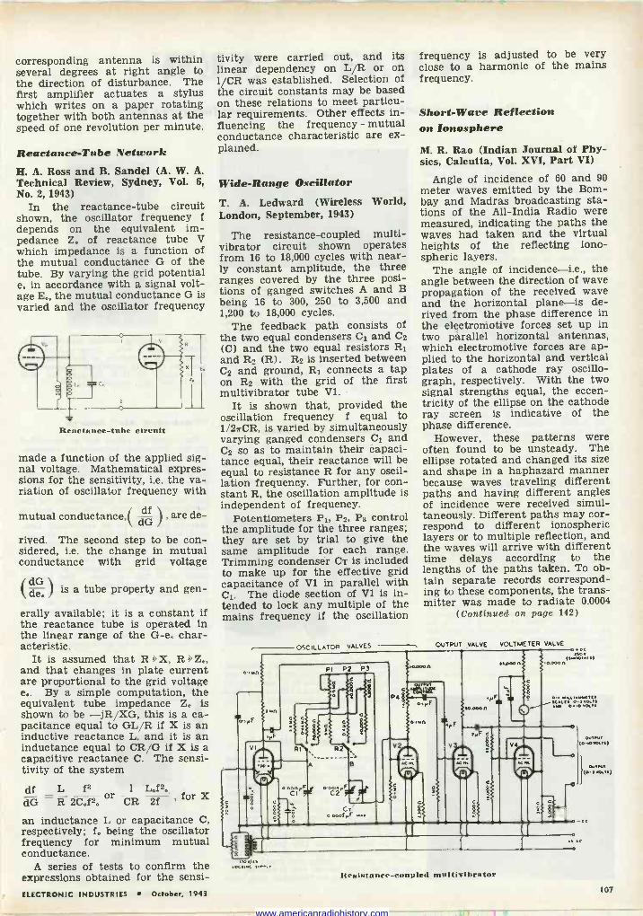
corresponding antenna is within several degrees at right angle to the direction of disturbance. The first amplifier actuates a stylus which writes on a paper rotating together with both antennas at the speed of one revolution per minute.
Reactance -Tube Network H. A. Ross and B. Sandel (A. W. A. Technical Review, Sydney, Vol. 6, No. 2, 1943)
In the reactance -tube circuit shown, the oscillator frequency f depends on the equivalent im- pedance Z. of reactance tube V which impedance is a function of the mutual conductance G of the tube. By varying the grid potential e. in accordance with a signal volt- age E., the mutual conductance G is varied and the oscillator frequency
Reactance -tube circuit
made a function of the applied sig- nal voltage. Mathematical expres- sions for the sensitivity, i.e. the va- riation of oscillator frequency with
mutual conductance,( dG , are de-
rived. The second step to be con- sidered, i.e. the change in mutual conductance with grid voltage
(dG de. is a tube property and gen-
erally available; it is a constant if the reactance tube is operated in the linear range of the G -e. char- acteristic.
It is assumed that R > X, R > Z., and that changes in plate current are proportional to the grid voltage e.. By a simple computation, the equivalent tube impedance Z. is shown to be -jR/XG, this is a ca- pacitance equal to GL/R if X is an inductive reactance L, and it is an inductance equal to CRAG if X is a capacitive reactance C. The sensi- tivity of the system
df L f3 1 L.f20
dG R 2C.f2. or CR 2f 1 for X
an inductance L or capacitance C, respectively; f. being the oscillator frequency for minimum mutual conductance.
A series of tests to confirm the expressions obtained for the sensi-
tivity were carried out, and its linear dependency on L/R or on 1/CR was established. Selection of the circuit constants may be based on these relations to meet particu- lar requirements. Other effects in- fluencing the frequency - mutual conductance characteristic are ex- plained.
Wide -Range Oscillator
T. A. Ledward (Wireless World, London, September, 1943)
The resistance -coupled multi - vibrator circuit shown operates from 16 to 18,000 cycles with near- ly constant amplitude, the three ranges covered by the three posi- tions of ganged switches A and B being 16 to 300, 250 to 3,500 and 1,200 to 18,000 cycles.
The feedback path consists of the two equal condensers C1 and C2
(C) and the two equal resistors R1 and R2 (R). R2 is inserted between C2 and ground, R1 connects a tap on R2 with the grid of the first multivibrator tube Vl.
It is shown that, provided the oscillation frequency f equal to 1/2irCR, is varied by simultaneously varying ganged condensers C1 and C2 so as to maintain their capaci- tance equal, their reactance will be equal to resistance R for any oscil- lation frequency. Further, for con- stant R, the oscillation amplitude is independent of frequency.
Potentiometers P1, P2, P3 control the amplitude for the three ranges; they are set by trial to give the same amplitude for each range. Trimming condenser CT is included to make up for the effective grid capacitance of Vl in parallel with C1. The diode section of Vl is in- tended to lock any multiple of the mains frequency if the oscillation
OSCILLATOR VALVES---
frequency is adjusted to be very close to a harmonic of the mains frequency.
Short -Wave Reflection on Ionosphere
M. R. Rao (Indian Journal of Phy- sics, Calcutta, Vol. XVI, Part VI)
Angle of incidence of 60 and 90 meter waves emitted by the Bom- bay and Madras broadcasting sta- tions of the All -India Radio were measured, indicating the paths the waves had taken and the virtual heights of the reflecting iono- spheric layers.
The angle of incidence-i.e., the angle between the direction of wave propagation of the received wave and the horizontal plane-is de- rived from the phase difference in the electromotive forces set up in two parallel horizontal antennas, which electromotive forces are ap- plied to the horizontal and vertical plates of a cathode ray oscillo - graph, respectively. With the two signal strengths equal, the eccen- tricity of the ellipse on the cathode ray screen is indicative of the phase difference.
However, these patterns were often found to be unsteady. The ellipse rotated and changed its size and shape in a haphazard manner because waves traveling different paths and having different angles of incidence were received simul- taneously. Different paths may cor- respond to different ionospheric layers or to multiple reflection, and the waves will arrive with different time delays according to the lengths of the paths taken. To ob- tain separate records correspond- ing to these components, the trans- mitter was made to radiate 0.0004
(Continued on page 142)
OUTPUT VALVE VOLTMETER VALVE
PI P2 P3
P4
A
0am.PF o-oa.2PF 390tGI C
C gó 0000IPF - .
C
¡looeo n
114
PF
a
O.
PF
.,oOO n (.-óó,:-.)
10.00011
w31 óé:Oaiii
V4
Y
0
0
3011. . , .,,
Resistance -coupled multivibratur
WIN, O-,0001.3.)
ELECTRONIC INDUSTRIES October, 1943 107
www.americanradiohistory.com
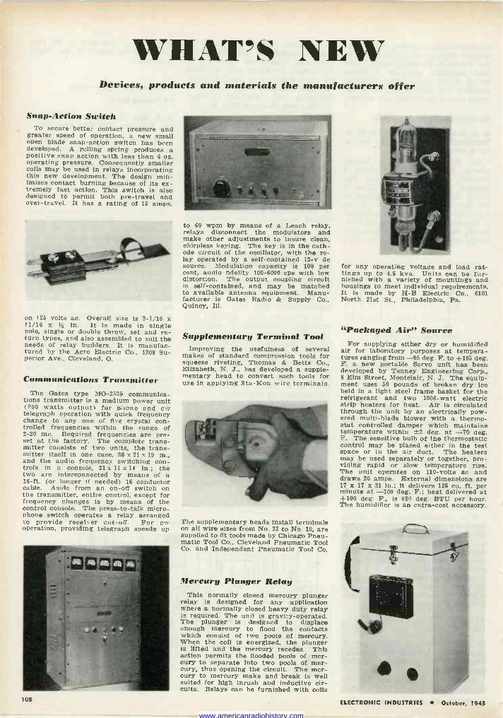
WHAT'S NERV Devices, products and materials the manufacturers offer
Snap -Action Switch To secure better contact pressure and
greater speed of operation, a new small open blade snap -action switch has been developed. A rolling spring produces a positive snap action with less than 6 oz. operating pressure. Consequently smaller coils may be used in relays incorporating this new development. The design min- imizes contact burning because of its ex- tremely fast action. This switch is also designed to permit both pre -travel and over -travel. It has a rating of 15 amps.
on 125 volts ac. Overall size is 1-1,16 x 11/16 x 1/2 in. It is made in single pole, single or double throw, set and re- turn types, and also assembled to suit the needs of relay builders. It is manufac- tured by the Acro Electric Co., 1308 Su- perior Ave., Cleveland, O.
Communications Transmitter The Gates type MO -2535 communica-
tions transmitter is a medium power unit (200 watts output) for phone and cw telegraph operation with quick frequency change to any one of five crystal con- trolled frequencies within the range of 2-20 mc. Required frequencies are pre- set at the factory. The complete trans- mitter consists of two units, the trans- mitter itself in one case, 36 x 21 x 19 in., and the audio frequency switching con- trols in a console, 21 x 11 x 14 in.; the two are interconnected by means of a 16 -ft. (or longer if needed) 16 conductor cable. Aside from an on -off switch on the transmitter, entire control, except for frequency changes is by means of the control console. The press -to -talk micro- phone switch operates a relay arranged to provide receiver cut-off. For ew operation, providing telegraph speeds up
to 60 wpm by means of a Leach relay, relays disconnect the modulators and make other adjustments to insure clean, chirpless keying. The key is in the cath- ode circuit of the oscillator, with the re- lay operated by a self-contained 12-v do source. Modulation capacity is 100 per cent, audio fidelity 100-6000 cps with low distortion. The output coupling circuit is self-contained, and may be matched to available antenna equipment. Manu- facturer is Gates Radio & Supply Co., Quincy, Ill.
Supplementary Terminal Tool Improving the usefulness of several
makes of standard compression tools for squeeze riveting, Thomas & Betts Co., Elizabeth, N. J., has developed a supple- mentary head to convert such tools for use in applying Sta-Kon wire terminals.
The supplementary heads install terminals on all wire sizes from No. 22 to No. 10, are supplied to fit tools made by Chicago Pneu- matic Tool Co., Cleveland Pneumatic Tool Co. and Independent Pneumatic Tool Co.
Mercury Plunger Relay This normally closed mercury plunger
relay is designed for any application where a normally closed heavy duty relay is required. The unit is gravity -operated. The plunger is designed to displace enough mercury to flood the contacts which consist of two pools of mercury. When the coil is energized, the plunger is lifted and the mercury recedes. This action permits the flooded pools of mer- cury to separate into two pools of mer- cury, thus opening the circuit. The mer- cury to mercury make and break is well suited for high inrush and inductive cir- cuits. Relays can be furnished with coils
for any operating voltage and load rat - tinge up to 4.5 kva. Units can be fur- nished with a variety of mountings and housings to meet individual requirements. It is made by H -B Electric Co., 6101 North 21st St., Philadelphia, Pa.
"Packaged Air" Source For supplying either dry or humidified
air for laboratory purposes at tempera- tures ranging from -95 deg. F. to +165 deg. F. a new portable Servo unit has been developed by Tenney Engineering Corp., 8 Elm Street, Montclair, N. J. The equip- ment uses 50 pounds of broken dry ice held in a light steel frame basket for the refrigerant and two 1000 -watt electric strip heaters for heat. Air is circulated through the unit by an electrically pow- ered multi -blade blower with a thermo- stat controlled damper which maintains temperature within {-2 deg. at -70 deg. F. The sensitive bulb of the thermostatic control may be placed either in the test space or in the air duct. The heaters may be used separately or together, pro- viding rapid or slow temperature rise. The unit operates on 110 -volts ac and draws 20 amps. External dimensions are 17 x 17 x 31 in.; it delivers 125 cu. ft. per minute at -100 deg. F.; heat delivered at +100 deg. F., is 680 deg. BTU per hour. The humidifier is an extra -cost accessory.
108 ELECTRONIC INDUSTRIES October, 1943
www.americanradiohistory.com
"How would you like to be hit several times with a hammer?"
Pity the Hytron tubes struck
several sharp blows by m L a heavy, swinging hammer
during the Bump Test. Only
by such rough treatment, can rugged Hytron tubes
suitable for the shocks of mechanized warfare be selected.
Even this trial is not enough. These qual- ity tubes must withstand many other mechanical shock tests during which the stability of electrical characteristics is
carefully measured while the tubes are tortured by scientifically simulated jolts
and vibrations which might occur in actual combat.
Hytron engineers are quality conscious. Whether the test be mechanical or elec- trical, their purpose is the same-to sup- ply our boys with tubes fit for service in bouncing jeeps, rattling tanks, shell - belching battleships, and darting, twist-
ing, roaring fighter planes. Wherever Hytron tubes may be called upon to act as the dependable hearts of radio and electronic fighting equipment, they must be the best that can be made.
OLDEST EXCLUSIVE MANUFACTURER OF RADIO RECEIVING TUBES
SALEM AND
EWguRYPORT, MASS.
ELECTRONIC INDUSTRIES October, 1943 109
www.americanradiohistory.com
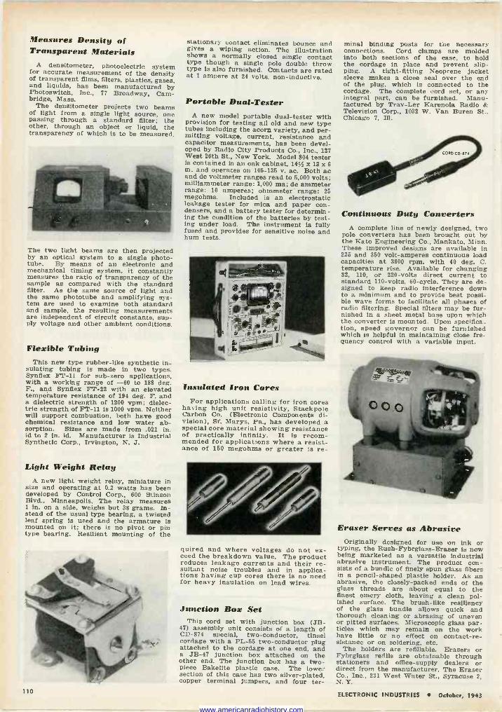
Measures Density of Transparent Materials
A densitometer, photoelectric system for accurate measurement of the density of transparent films, filters, plastics, gases, and liquids, has been manufactured by Photoswitch, Inc., 77 Broadway, Cam- bridge, Mass.
The densitometer projects two beams of light from a single light source, one passing through a standard filter; the other, through an object or liquid, the transparency of which is to be measured.
The two light beams are then projected by an optical system to a single photo - tube. By means of an electronic and mechanical timing system, it constantly measures the ratio of transparency of the sample as compared with the standard filter. As the same source of light and the same phototube and amplifying sys- tem are used to examine both standard and sample, the resulting measurements are independent of circuit constants, sup- ply voltage and other ambient conditions.
Flexible Tubing This new type rubber -like synthetic in-
sulating tubing is made in two types. Synfiex FT -11 for sub -zero applications, with a working range of -60 to 188 deg. F., and Synfiex FT -22 with an elevated temperature resistance of 194 deg. F. and a dielectric strength of 1200 vpm; dielec- tric strength of FT -11 is 1000 vpm. Neither will support combustion, both have good chemical resistance and low water ab- sorption. Sizes are made from .021 in. id to 2 in. id. Manufacturer is Industrial Synthetic Corp., Irvington, N. J.
Light Weight Relay A new light weight relay, miniature in
size and operating at 0.2 watts has been developed by Control Corp., 600 Stinson Blvd., Minneapolis. The relay measures 1 in. on a side, weighs but 38 grams. In- stead of the usual type bearing, a twisted leaf spring is used and the armature is mounted on it; there is no pivot or pin type bearing. Resilient mounting of the
stationary contact eliminates bounce and gives a wiping action. The illustration shows a normally closed single contact type though a single pole double throw type is also furnished. Contacts are rated at 1 ampere at 24 volts, non -inductive.
Portable Dual -Tester A new model portable dual -tester with
provision for testing all old and new type tubes including the acorn variety, and per- mitting voltage, current, resistance and capacitor measurements, has been devel- oped by Radio City Products Co., Inc., 127 West 26th St., New York. Model 804 tester is contained in an oak cabinet, 1454 x 13 x 6 in. and operates on 105-135 v. ac. Both ac and dc voltmeter ranges read to 5,000 volts; milliammeter range: 1,000 ma; dc ammeter range: 10 amperes; ohmmeter range: 25 megohms. Included is an electrostatic leakage tester for mica and paper con- densers, and a battery tester for determin- ing the condition of the batteries by test- ing under load. The instrument is fully fused and provides for sensitive noise and hum tests.
Insulated Iron Cores For applications calling for iron cores
having high unit resistivity, Stackpole Carbon Co. (Electronic Components di- vision), St. Marys, Pa., has developed a special core material showing resistance of practically infinity. It is recom- mended for applications where a resist- ance of 150 megohms or greater is re-
quired and where voltages do not ex- ceed the breakdown value. The product reduces leakage currents and their re- sultant noise troubles and in applica- tions having cup cores there is no need for heavy insulation on lead wires.
Junction Box Set This cord set with junction box (JB-
47) assembly unit consists of a length of CD -874 special, two -conductor, tinsel cordage with a PL -55 two -conductor plug attached to the cordage at one end, and a JB-47 junction box attached on the other end. The junction box has a two- piece Bakelite plastic case. The lower section of this case has two silver-plated, copper terminal jumpers, and four ter-
minal binding posts for the necessary connections. Cord clamps are molded into both sections of the case, to hold the cordage in place and prevent slip- ping. A tight -fitting Neoprene jacket sleeve makes a close seal over the end of the plug, which is connected to the cordage. The complete cord set, or any integral part, can be furnished. Manu- factured by Trav-Ler Karenola Radio K Television Corp., 1032 W. Van Buren St., Chicago 7, Ill.
Continuous Duty Converters A complete line of newly designed, two
pole converters has been brought out b(v the Kato Engineering Co., Mankato, Minn. These improved designs are available in 225 and 350 volt-amperes continuous load capacities at 3600 rpm. with 40 deg. C. temperature rise. Available for changing 32, 110, or 220 -volts direct current to standard 110 -volts, 40 -cycle, They are de- signed to keep radio interference down to a minimum and to provide best possi- ble wave forms to facilitate all phases of radio filtering. Special filters may be fur- nished in a sheet metal base upon which the converter is mounted. Upon specifica- tion, speed governor can be furnished which is helpful in maintaining close fre- quency control with a variable input.
Eraser Serves as Abrasive Originally designed for use on ink or
typing, the Rush-Fybrglass-Eraser is now being marketed as a versatile industrial abrasive instrument. The product con- sists of a bundle of finely spun glass fibers in a pencil -shaped plastic holder. As an abrasive, the closely -packed ends of the glass threads are about equal to the finest emery cloth, leaving a clean pol- ished surface. The brush -like resiliency of the glass bundle allows quick and thorough cleaning or abrasing of uneven or pitted surfaces. Microscopic glass par- ticles which may remain on the work have little or no effect on contact -re- sistance or on soldering, etc.
The holders are refillable. Erasers or Fybrglass refills are obtainable through stationers and office -supply dealers or direct from the manufacturer, The Eraser Co., Inc., 231 West Water St., Syracuse 2, N. Y.
110 ELECTRONIC INDUSTRIES October, 1943
www.americanradiohistory.com
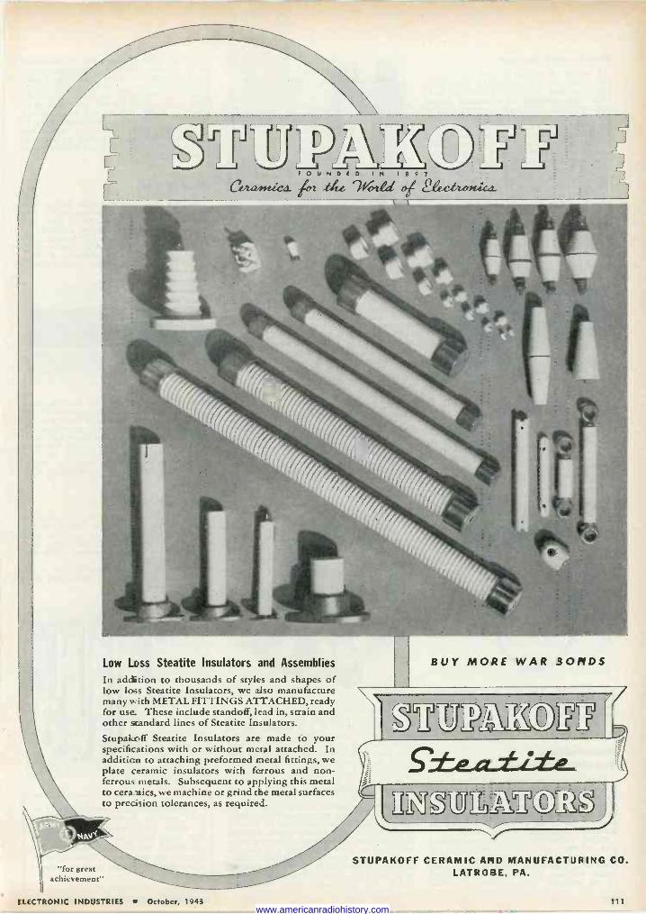
/-\\ F O D E D IN 7 8 9 7
( i2et2l.ci1 At-r.tt.e r2.a el 2.ecttcnúc s.
Low Loss Steatite Insulators and Assemblies
In addition to thousands of styles and shapes of low loss Steatite Insulators, we also manufacture many with METAL FITTINGS ATTACHED, ready for use. These include standoff, lead in, strain and other standard lines of Steatite Insulators.
Stupakr.ff Steatite Insulators are made to your specifications with or without metal attached. In addition to attaching preformed metal fittings, we plate ceramic insulators with ferrous and non- ferrous metals. Subsequent to applying this metal to cera-nics, we machine or grind the metal surfaces to precision tolerances, as required.
7
BUY MORE WAR BONDS
S'±e.42-±£±2-*
STUPAKOFF CERAMIC AND MANUFACTURING CO. LATROBE, PA. "for great
achievement"
ELECTRONIC INDUSTRIES October, 1943 111 www.americanradiohistory.com
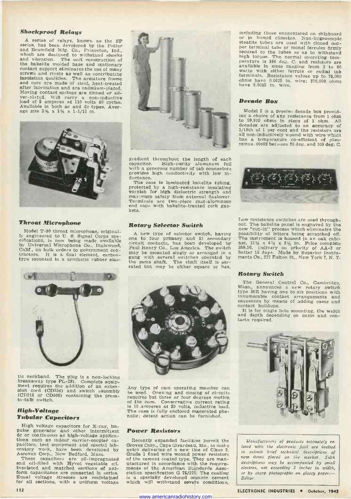
Shockproof Relays A series of relays, known as the SP
series, has been developed by the Potter and Brumfield Mfg. Co., Princeton, Ind., which are designed to withstand shocks and vibration. The unit construction of the bakelite molded base and stationary contact support eliminates the use of many screws and rivets as well as contributing insulation qualities. The armature frame and core are made of steel, heat -treated after fabrication and are cadmium -plated. Moving contact springs are tinned or sil- ver-plated. Will carry a non -inductive load of 5 amperes at 110 volts 60 cycles. Available in both ac and dc types. Aver- age size 2% x 1% x 1-1/12 in.
Throat Microphone Model T-30 throat microphone, original-
ly engineered to Ti. S. Signal Corps spe- cifications, is now being made available by Universal Microphone Co., Inglewood, Calif., on bulk orders to government con- tractors. It is a dual element, carbon - type mounted in a synthetic rubber elas-
tic neckband. The plug is a non -locking breakaway type PL -291. Complete equip- ment requires the addition of an exten- sion cord (CD354) and switch assembly (CD318 or CD508) containing the press - to -talk switch.
High -Voltage Tubular Capacitors
High voltage capacitors for X-ray, im- pulse generator and other intermittent dc or continuous ac high -voltage applica- tions such as indoor carrier -coupler ca- pacitors, test equipment and special lab- oratory work, have been developed by Aerovox Corp., New Bedford, Mass.
These capacitors are oil -impregnated and oil -filled with Hyvol vegetable oil. Insulated and matched sections of uni- form capacitance are connected in series. Equal voltage stresses are maintained for all sections, with a uniform voltage
gradient throughout the length of each capacitor. High -purity aluminum foil with a generous number of tab connectors provides high conductivity with low in- ductance.
The case is laminated bakelite tubing, protected by a high -resistance insulating varnish for high dielectric strength and maximum safety from external flashover. Terminals are two-piece cast -aluminum end caps with bakelite-treated cork gas- kets.
Rotary Selector Switch A new type of selector switch, having
one to four primary and 12 secondary circuit contacts, has been developed by Paul Henry Co., Los Angeles. The switch may be mounted singly or arranged in a gang with several switches operated by the same shaft. The shaft itself is ser- rated but may be either square or hex.
Any type of cam operating member can be used. Opening and closing of circuits requires but three or four degrees motion of the cam. Conservative current rating is 10 amperes at 29 volts, inductive load. The case is fully enclosed macerated phe- nolic; detent action can be furnished.
Power Resistors Recently expanded facilities permit the
Groves Corp., Cape Girardeau, Mo., to make quick deliveries of a new line of Class 2, Grade 1 fixed wire wound power resistors of the cement coated type. They are man- ufactured in accordance with the require- ments of the American Standards Asso- ciation specification G 75/370. The coating is a specially developed organic cement which will withstand severe conditions,
including those encountered on shipboard or in humid climates. Non -hygroscopic steatite tubes are used with tinned cop- per terminal tabs or monel ferrules firmly secured to the tubes so as to withstand high torque. The normal operating tem- perature is 160 deg. C. and resistors are available in sizes ranging from 2 to 80 watts with either ferrule or radial tab terminals. Resistance values up to 75,000 ohms have 0.0025 in. wire; 270,000 ohms have 0.0015 in. wire.
Decade Box Model 5 is a precise decade box provid-
ing a choice of any resistance from 1 ohm to 99,999 ohms in steps of 1 ohm. All decades are adjusted to an accuracy of 1/10th of 1 per cent and the resistors are all non -inductively wound with wire which has a temperature co -efficient of plus - minus .00002 between 20 deg. and 100 deg. C.
Low resistance switches are used through- out. The bakelite panel is engraved by the new "cut -in" process which eliminates the possibility of letters being scratched off. The instrument is housed in an oak cabi- net, 181 x 61/2 x 31 in. Price complete $59.50. Delivery on priority of AA -3 or better 15 days. Made by Superior Instru- ments Co., 227 Fulton St., New York 7, N. Y.
Rotary Switch The General Control Co., Cambridge,
Mass., announces a new rotary switch type MR having one to six positions with innumerable contact arrangements and sequences by means of adding cams and contact buildups.
It is for single hole mounting, the width and depth depending on cams and con- tacts required.
iVfanufacturers of Products intimately re- lated with the electronic field are invited to submit brief technical descriptions of new items placed on the market. Such descriptions may be accompanied by small electros, not exceeding 2 inches in width, or by sharp photographs on glossy paper.- Editor.
112 ELECTRONIC INDUSTRIES S October, 1943 www.americanradiohistory.com
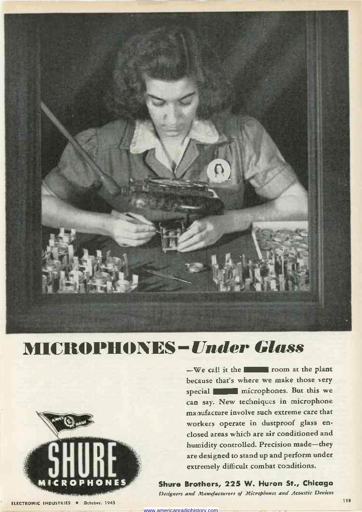
MICROPHONES - Mader dass -We call it the room at the plant because that's where we make those very
special microphones. But this we
can say. New techniques in microphone manufacture involve such extreme care that
workers operate in dustproof glass en-
closed areas which are air conditioned and
humidity controlled. Precision made-they are designed to stand up and perform under
extremely difficult combat conditions.
Shure Brothers, 225 W. Huron St., Chicago Designers and Manufacturers of Microphones and Acoustic Devices
ELECTRONIC INDUSTRIES October, 1943 113
www.americanradiohistory.com
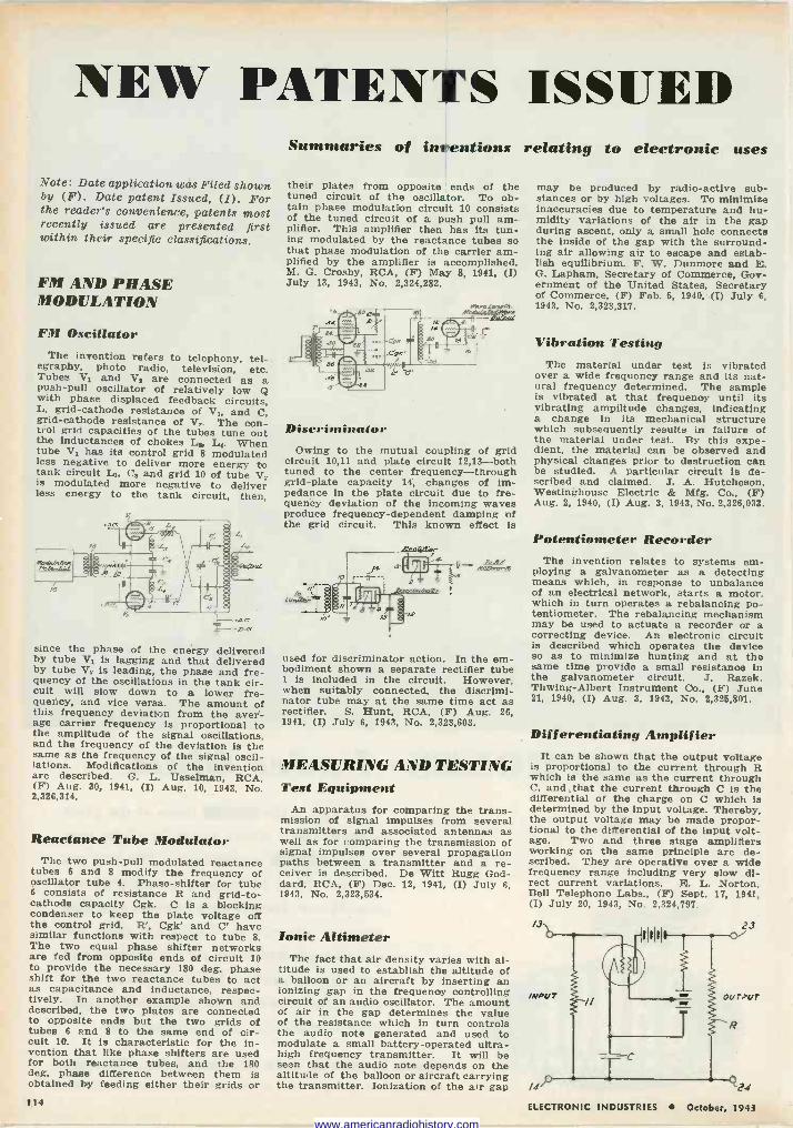
NEW PATENTS ISSUED
Note: Date application was Filed shown by (F). Date patent Issued, (I). For the reader's convenience, patents most recently issued are presented first within their specific classifications.
FM AND PHASE MODULATION
FM Oscillator The invention refers to telephony, tel- egraphy, photo radio, television, etc. Tubes V1 and V, are connected as a push-pull oscillator of relatively low Q with phase displaced feedback circuits,
L, grid -cathode resistance of V,, and C, grid -cathode resistance of V,. The con- trol grid capacities of the tubes tune out the inductances of chokes L2, L*. When tube V, has its control grid 8 modulated less negative to deliver more energy to tank circuit L1, Ca and grid 10 of tube V, is modulated more negative to deliver less energy to the tank circuit, then,
since the phase of the energy delivered by tube V1 is lagging and that delivered by tube Va is leading, the phase and fre- quency of the oscillations in the tank cir- cuit will slow down to a lower fre- quency, and vice versa. The amount of this frequency deviation from the aver- age carrier frequency is proportional to the amplitude of the signal oscillations, and the frequency of the deviation is the same as the frequency of the signal oscil- lations. Modifications of the invention are described. G. L. Usselman, RCA, (F) Aug. 30, 1941, (I) Aug. 10, 1943. No. 2,326,314.
Reactance Tube Modulator The two push-pull modulated reactance
tubes 6 and 8 modify the frequency of oscillator tube 4. Phase -shifter for tube 6 consists of resistance R and grid -to - cathode capacity Cgk. C is a blocking condenser to keep the plate voltage off the control grid. R', Cgk' and C' have similar functions with respect to tube 8. The two equal phase shifter networks are fed from opposite ends of circuit 10 to provide the necessary 180 deg. phase shift for the two reactance tubes to act as capacitance and inductance, respec- tively. In another example shown and described, the two plates are connected to opposite ends but the two grids of tubes 6 and 8 to the same end of cir- cuit 10. It is characteristic for the in- vention that like phase shifters are used for both reactance tubes, and the 180 deg. phase difference between them is obtained by feeding either their grids or
Summaries of inventions relating to electronic uses
their plates from opposite ends of the tuned circuit of the oscillator. To ob- tain phase modulation circuit 10 consists of the tuned circuit of a push pull am- plifier. This amplifier then has its tun- ing modulated by the reactance tubes so that phase modulation of the carrier am- plified by the amplifier is accomplished. M. G. Crosby, RCA, (F) May 8, 1941, (I) July 13, 1943, No. 2,324,282.
Discriminator Owing to the mutual coupling of grid
circuit 10,11 and plate circuit 12,13 -both tuned to the center frequency -through grid -plate capacity 14, changes of im- pedance in the plate circuit due to fre- quency deviation of the incoming waves produce frequency -dependent damping of the grid circuit. This known effect is
ToFf A2112efe
used for discriminator action. In the em- bodiment shown a separate rectifier tube 1 is included in the circuit. However, when suitably connected, the discrimi- nator tube may at the same time act as rectifier. S. Hunt, RCA, (F) Aug. 26, 1941, (I) July 6, 1943, No. 2,323,603.
MEASURING AND TESTING Test Equipment
An apparatus for comparing the trans- mission of signal impulses from several transmitters and associated antennas as well as for comparing the transmission of signal impulses over several propagation paths between a transmitter and a re- ceiver is described. De Witt Rugg God- dard, RCA, (F) Dec. 12, 1941, (I) July 6, 1943, No. 2,323,634.
Ionic Altimeter The fact that air density varies with al-
titude is used to establish the altitude of a balloon or an aircraft by inserting an ionizing gap in the frequency controlling circuit of an audio oscillator. The amount of air in the gap determines the value of the resistance which in turn controls the audio note generated and used to modulate a small battery -operated ultra- high frequency transmitter. It will be seen that the audio note depends on the altitude of the balloon or aircraft carrying the transmitter. Ionization of the air gap
may be produced by radio -active sub- stances or by high voltages. To minimize inaccuracies due to temperature and hu- midity variations of the air in the gap during ascent, only a small hole connects the inside of the gap with the surround- ing air allowing air to escape and estab- lish equilibrium. F. W. Dunmore and E. G. Lanham, Secretary of Commerce, Gov- ernment of the United States, Secretary of Commerce, (F) Feb. 5, 1940, (I) July 6, 1943, No. 2,323,317.
Vibration Testing The material under test is vibrated
over a wide frequency range and its nat- ural frequency determined. The sample is vibrated at that frequency until its vibrating amplitude changes, indicating a change in its mechanical structure which subsequently results in failure of the material under test. By this expe- dient, the material can be observed and physical changes prior to destruction can be studied. A particular circuit is de- scribed and claimed. J. A. Hutcheson, Westinghouse Electric & Mfg. Co., (F) Aug. 2, 1940, (I) Aug. 3, 1943, No. 2,326,033.
Potentiometer Recorder The invention relates to systems em-
ploying a galvanometer as a detecting means which, in response to unbalance of an electrical network, starts a motor, which in turn operates a rebalancing po- tentiometer. The rebalancing mechanism may be used to actuate a recorder or a correcting device. An electronic circuit is described which operates the device so as to minimize hunting and at the same time provide a small resistance in the galvanometer circuit. J. Razek, Thwing-Albert Instrument Co., (F) June 21, 1940, (I) Aug. 3, 1943, No. 2,325,801.
Differentiating Amplifier It can be shown that the output voltage
is proportional to the current through R which is the same as the current through C, and that the current through C is the differential of the charge on C which is determined by the input voltage. Thereby, the output voltage may be made propor- tional to the differential of the input volt- age. Two and three stage amplifiers working on the same principle are de- scribed. They are operative over a wide frequency range including very slow di- rect current variations. E. L. Norton, Bell Telephone Labs., (F) Sept. 17, 1941,. (I) July 20, 1943, No. 2,324,797.
/3 23
INPUT ourPur
/4 24 114 ELECTRONIC INDUSTRIES October, 1943
www.americanradiohistory.com
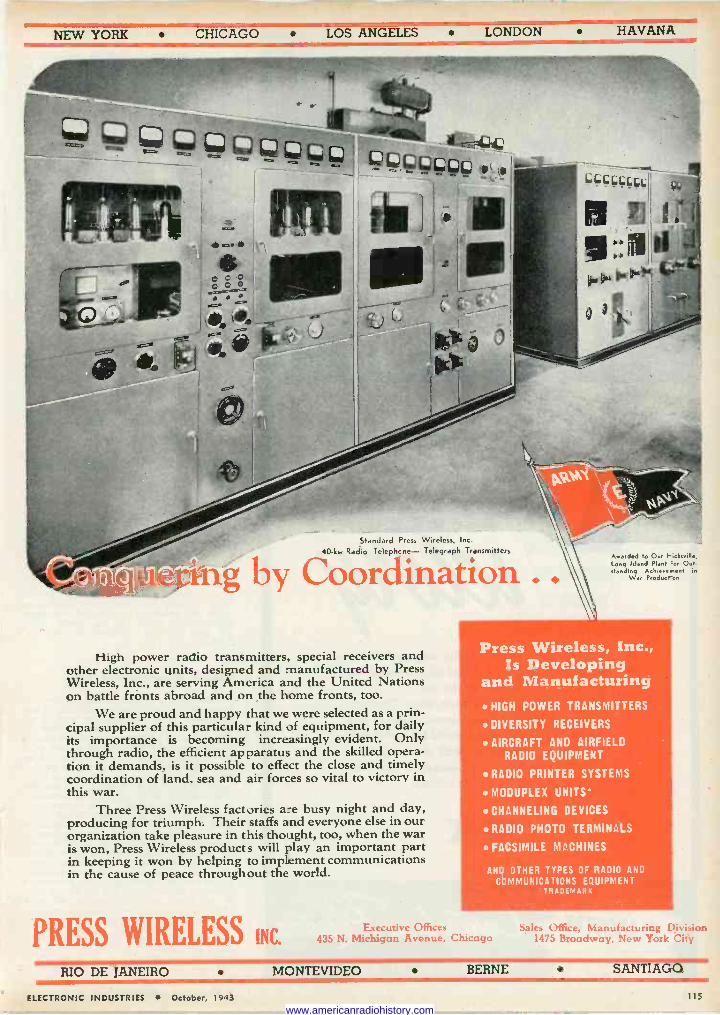
NEW YORK CHICAGO LOS ANGELES LONDON HAVANA
Standard Press Wireless, Inc.
40 -kw Radio Telephone- Telegraph Transmitters
g by Coordination
High power radio transmitters. special receivers and other electronic units, designed and manufactured by Press Wireless, Inc., are serving America and the United Nations on battle fronts abroad and on the home fronts, too.
We are proud and happy that we were selected as a prin- cipal supplier of this particular kind of equipment, for daily its importance is becoming increasingly evident. Only through radio, the efficient apparatus and the skilled opera- tion it demands, is it possible to effect the close and timely coordination of land. sea and air forces so vital to victory in this war.
Three Press Wireless factories are busy night and day, producing for triumph. Their staffs and everyone else in our organization take pleasure in this thought, too, when the war is. won, Press Wireless products will play an important part in keeping it won by helping to implement communications in the cause of peace throughout the world.
PRESS WIRELESS INC.
Awarded to Our hick..ille, long Island Plant 'or Out. standing Achiere.nent ,n
war Product on
Press Wireless, Inc., Is Developing
and Manufacturing HIGH POWER TRANSMITTERS
DIVERSITY RECEIVERS
AIRCRAFT AND AIRFIELD RADIO EQUIPMENT
RADIO PRINTER SYSTEMS
MODUPLEX UNITS'
CHANNELING DEVICES
RADIO PHOTO TERMINALS
FACSIMILE MACHINES
AND OTHER TYPES OF RADIO AND
COMMUNICATIONS EQUIPMENT TRADEMARK
Executive Offices 435 N. Michigan Avenue. Chicago
i
Sales Office, Manufacturing Division 1475 Broadway, New York City
RIO DE JANEIRO MONTEVIDEO BERNE SANTIAGO
ELECTRONIC INDUSTRIES October, 1943 115
www.americanradiohistory.com
tIIOS1aT
ROLLING ON TO
* Clarostat continues to be engaged 100% in the most important job of all-winning the war-on land, sea and in the air.
But after victory has been won, Clarostat promises the trade-servicemen, jobbers and others-that Clarostat products for initial and replacement uses alike, will once more be generally available for peacetime pursuits. Meanwhile, let's keep 'em rolling!
CLAROSTAT
.... CLAROSTAT MFG. CO., Inc. 285-1 N. 6th St., Brooklyn, N.Y.
Wire -Testing Apparatus The apparatus described includes a
vacuum tube oscillator. The wire to be tested is rapidly moved along the axis of the tank -circuit coil, controlling its self-inductance. For the desired wire characteristics the oscillator produces oscillations which are indicated by a mil- liammeter in the plate circuit. Upon a change in the wire characteristics and in the coil inductance oscillations will cease causing a drop in plate current. A neon lamp is so connected in the cir- cuit that it does not glow while the oscil- latos operates, but lights as soon as os- cillations cease and stays lighted until manual operation of a switch by the operator. By this expedient, continuous observation of the device is made un- necessary. D. E. Elmendorf et al., Gen- eral Electric Co., (F) June 25, 1941, (I) Aug. 10, 1943, No. 2,326,344.
TELEVISION
Measuring Frequency Changes It may be necessary, for instance with
regard to television synchronizing signals, to determine the rate of changes of some frequency. According to the invention, a beat frequency between the unknown frequency and a standard is derived. The resulting difference frequency is elec- trically differentiated in a resistor -con- denser network, recorded by an ammeter and/or indicated by a cathode-ray oscii- lograph. 1f desirable, the original fre- quency may be multiplied and/or the wave -shape transformed to that of a purely sinusoidal wave. E. D. Goodale, (F) Dec. 27, 1941, (I) July 13, 1943, No. 2,324,077.
Television Tube
The invention concerns tubes where the electron beam is directed upon the target or mosaic electrode with a veloc- ity approaching zero so that no second- ary electrons are liberated, and where the electron paths are at right angles to the target electrode in the proximity of the latter. These electron beam character- istics are obtained by suitably arranging electrostatic fields. H. A. lams, RCA, (F) Dec. 28, 1940, (I) June 29, 1943, No. 2,322,807.
Image Reproducing Tube
Essentially voltages representing point by point the picture to be reproduced are impressed upon an insulating grid of an electron tube so that different parts of the grid are at different potentials at any given moment. The grid is flooded with a continuous stream of electrons which is modulated to a different extent at dif- ferent points of the grid and, upon pas- sage there -through, forms a current the cross-section of which is representative of the optical image. This current im- pinges upon a fluorescent target elec- trode. Various suitable insulating grid structures are described, using secondary emission-in which case th ecathode emits an electron stream representative of the picture - photosensitive coatings, heat - sensitive coatings or photo -conductive coatings - in which case the picture is projected directly onto the insulating grid. In all these latter instances, the grid structure is such that voltages are de- veloped over the surface of the grid which vary across the surface of the grid in accordance with the variations of light and shadow in the optical image projected thereupon. H. A. Iams, RCA, (F) Dec. 14, 1937, (I) June 22, 1943, No. 2,322,361.
116 ELECTRONIC INDUSTRIES October, 1943
www.americanradiohistory.com
THE PEACETIME
MEASURES OF
REFLECTION AND
DEFLECTION .... WILL BE READ FROM
T PUTT ELECTRICAL MEASURING INSTRUMENTS
WITH CONFIDENCE
AND ECONOMY
THE TRIPLETT ELECTRICAL INSTRUMENT CO., BLUFFTON,
BACK UP YOUR BELIEF IN AMERICA... Lu/Y WAR BONDS
ELECTRONIC INDUSTRIES October, 1943
rr
117
www.americanradiohistory.com
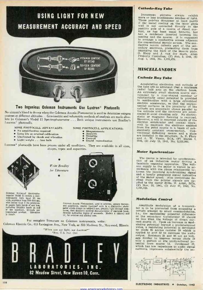
Cathode -Ray Tube
USING LIGHT FOR NEW
MEASUREMENT ACCURACY AND SPEED
Two Ingenious Coleman Instruments Use Luxtron* Photocells No airman's blood is drawn when the Coleman Anoxia Photometer is used to determine oxygen content at different altitudes... Gravimetric and volumetric methods of analysis are made obso- lete by Coleman's Model 11 Spectrophotometer ... Both unique instruments use Bradley's Luxtron* photocells.
SOME PHOTOCELL ADVANTAGES: No amplification required Long life at original calibration Unaffected by shock and vibration Light weight ... less bulk
SOME PHOTOCELL APPLICATIONS: Measurements Analysis Metering Control Sound reproduction
Luxtron* photocells have been proven under all conditions. They are available in all sizes, shapes, types and capacities.
Coleman Universal Spectropho- tometer Model 11 selects a mon- ochromatic light band 35 mu wide, anywhere from 300-800 mu, with better than 2 mu precision. It passes light bands of any hue, including invisible bands at end of the spectrum, through any translucent product. Operation is simple.
Write Bradley for Literature
Coleman Anoxia Photometers, used in aviation, oxygen therapy, and anesthesia, employ Luxtron* cells in a diminutive photo- meter which clamps on subject's ear, projects light through mem- brane, then measures spectral characteristics of emergent beam, directly indicating degree of anoxemia. Modele A (above) and 17, for aviation and clinical uses.
For complete literature on Coleman instruments, write: Coleman Electric Co., 415 Lexington Ave., New York, or 310 Madison St., Maywood, Illinois.
"When you use light, use Luxtron* *REG. U.S. PAT. OFF.
BRADLEY LABORATORIES, INC. 82 Meadow Street, New Haven 10, Conn.
Iconoscope pictures always exhibit more or less troublesome patches of light. These patches disappear at least partly if the metal coating on the inner glass wall is not connected directly to the positive pole of a source of direct cur- rent, as has been usual hitherto, but has a condenser inserted between the coating and the source. It is suggested to arrange a conductive screen adjacent the conventional mosaic screen. The con- ductive screen collects part of the sec- ondary electrons, preventing them from impinging the back of the mosaic plate. G. Hepp and J. van der Mark, Alien Property Custodian, (F) Feb. 2, 1942, (I) Aug. 3, 1943, No. 2,325, 676.
MISCELLANEOUS
Cathode Ray Tube Accelerating electrodes and cathode of the tube are so arranged that a minimum
radial field acts on the electron beam. An extremely small electron source sur- rounded by a ring -shaped member of substantially equal potential is provided in combination with a large cylindrical electron accelerator, so that the equipo- tential surfaces in the proximity of the cathode are essentially planes parallel to the cathode and the electrons are accel- erated in axial direction only. No electro- static or magnetic focusing is required. However, a coil is mounted outside of the electron accelerator and coaxial there- with to maintain the electrons emitted from the point source in a beam of sub- stantially constant cross-section. Con- ventional deflecting means and a plate are included in the structure. L. E. Flory and A. W. Vance, RCA, (F) March I, 1941, (I) July 13, 1943, No. 2,323,986.
Motor Synchronizer The device is intended for synchroniza-
tion of an induction motor driving a facsimile scanning apparatus. The volt- age supply to the motor is varied in ac- cordance with the phase relationship be- tween the incoming synchronizing signal and a locally generated signal indicative of the motor speed. Also corrections de- rived from the printer signals are ap- plied to the motor drive. M. Artzt, RCA, (F) Nov. 28, 1941, (I) July 27, 1943, No. 2,325,028.
Modulation Control Amplitude modulation of a transmit- ter is to be prevented from exceeding a certain amount to avoid overmodulation,
i.e., the modulating potential difference at the secondary transformer 12 should be less than the voltage of direct cur- rent source 13. Upon an increase in mod- ulating potential beyond a predetermined value, a regulating potential is developed by diode 28 across resistor 29 which is applied to grid 32 to decrease the audio output. Resistors 25 and 26 act as volt- age divider to impress across diode 28 only a portion of the unidirectional po- tential from source 13. Condenser 27, which has low impedance to audio signal currents, impresses substantially the en -
13 Q H s L,] EilE .: 'rTF
C,:..
3_i L
2E:
11
H
118 ELECTRONIC INDUSTRIES October, 1943
www.americanradiohistory.com
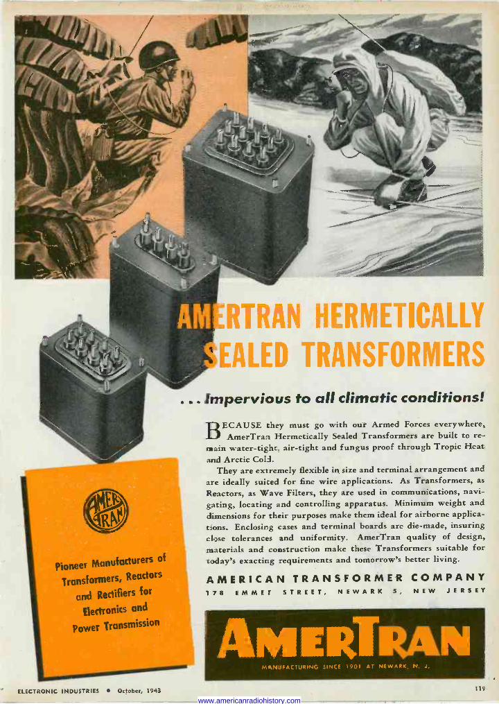
Pioneer Manufacturers of
Transformers, Reactors
and Rectifiers for
Electronics and
Power Transmission'
RTRAN HERMETICALLY
EALED TRANSFORMERS
... Impervious to all climatic conditions!
BECAUSE they must go with our Armed Forces everywhere, AmerTran Hermetically Sealed Transformers are built to re-
main water -tight. air -tight and fungus proof through Tropic Heat and Arctic Coli.
They are extremely flexible in size and terminal arrangement and are ideally suited for fine wire applications. As Transformers, as
Reactors, as Wave Filters, they are used in communications, navi- gating, locating and controlling apparatus. Minimum weight and dimensions for their purposes make them ideal for airborne applica- tions. Enclosing cases and terminal boards are die -made, insuring close tolerances and uniformity. AmerTran quality of design, materials and construction make these Transformers suitable for today's exacting requirements and tomorrow's better living.
AMERICAN TRANSFORMER COMPANY 1 7 8 E M M E T STREET, NEWARK 5, NEW JERSEY
AMERTI?AN MANUFACTURING SINCE 1901 AT NEWARK, N. J.
ELECTRONIC INDUSTRIES October, 1943 119
www.americanradiohistory.com
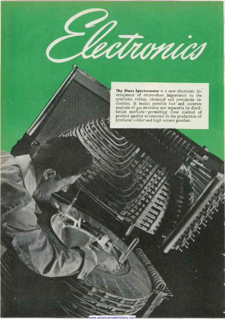
The Mass Spectrometer is à new electronic de- velopment of tremendous importance to the synthetic rubber, chemical and petroleum in- dustries. It makes possible fast and accurate analysis of gas mixtures not separable by distil- lation methods-permitting close control of product quality so essential in the production of synthetic rubber and high octane gasoline.
www.americanradiohistory.com
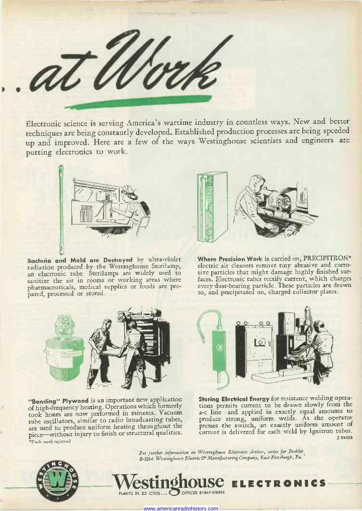
Electronic science is serving America's wartime industry in countless ways. New and better
techniques are being constantly developed. Established production processes are being speeded
up and improved. Here are a few of the ways Westinghouse scientists and engineers are
putting electronics to work.
Bacteria and Mold are Destroyed by ultra-violet radiation produced by the Westinghouse Sterilamp, an electronic tube. Sterilamps are widely used to sanitize the air in rooms or working areas where pharmaceuticals, medical supplies or foods are pre- pared, processed or stored.
"Bonding" Plywood is an important new application of high -frequency heating. Operations which formerly took hours are now performed in minutes. Vacuum tube oscillators, similar to radio broadcasting tubes, are used to produce uniform heating throughout the piece-without injury to finish or structural qualities. *Trade mark registered
Where Precision Work is carried on, PRECIPITRON* electric air cleaners remove tiny abrasive and corro- sive particles that might damage highly finished sur- faces. Electronic tubes rectify current, which charges every dust -bearing particle. These particles are drawn to, and precipitated on, charged collector plates.
Tr.)
Storing Electrical Energy for resistance welding opera- tions permits current to be drawn slowly from the a -c line-and applied in exactly equal amounts to produce strong, uniform welds. As the operator presses the switch, an exactly uniform amount of current is delivered for each weld by Ignitron tubes.
J-91033
For further information on Westinghouse Electronic devices, write for Booklet
B-3264. Westinghouse Electric dT Manufacturing Company, East Pittsburgh, Pa.
\Vestinghouse ELECTRONICS PLANTS IN 25 CITIES...OFFICES EVERYWHERE
www.americanradiohistory.com
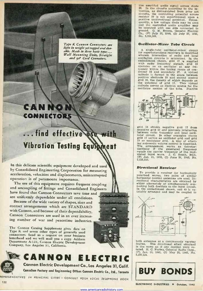
CAN CONNECTO
Type K Cannon Connectors are light in weight yet rugged a ad dur- able. Made in three basic types... Wall Mounting Units, Straight
and 900 Cord Connecters.
..- . . . find effective ele;
Vibration Testing Equipment
In this delicate scientific equipment developed and used by Consolidated Engineering Corporation for measuring acceleration, velocities and displacements, uninterrupted operation is of paramount importance.
The use of this equipment requires frequent coupling and uncoupling of fittings and Consolidated Engineers have found that Cannon Connectors save time and are uniformly dependable under all conditions.
Because of the wide variety of shapes, sizes and contact arrangements which are STANDARD with Cannon, and because of their dependability, Cannon Connectors are used in an ever increas- ing number of war and peacetime industries.
The Cannon Catalog Supplement gives data on Type K and seven other types of generally used connectors. Send us a request on your business letterhead and we will mail you a copy. Address Department A-122, Cannon Electric Development Company, Los Angeles 31, California.
eer, CANNON ELECTRIC Cannon Electric Development Co., Los Angeles 31, Calif. Canadian Factory and Engineering Office: Cannon Electric Co., Ltd., Toronto
REPRESENTATIVES IN PRINCIPAL CITIES - CONSULT YOUR LOCAL TELEPHONE BOOK
tire amplified audio signal across diode 28. In the circuits according to the in- vention, as distinguished from prior art circuits, the controlling potential across resistor 29 is not superimposed upon a positive unidirectional potential. Conse- quently, a low voltage diode may be used and the controlled audio amplifier may be operated with one side connected to ground. G. M. Brown, General Electric Co., (F) July 23, 1940, (I) July 27, 1943, No. 2,325,366.
Oscillator -Mixer Tube Circuit A single -tube oscillator -mixer circuit
for superheterodyne receivers is described wherein interaction of radio and local oscillation circuits is minimized. In the embodiment shown, grid 17 is supplied with radio frequency signals, grid 19 operates as an oscillator at any fre- quency within the tuning range of con- denser 28 and secondary 27. A virtual cathode is formed in the space between positive electrode 18 and second control grid 19, the density of which depends on the potential of grid 17. This virtual cathode serves as electron source for the oscillator section of the tube. Positive
.2021
22
grid 18 shields negative grid 17 from negative grid 19 and prevents interaction between radio frequency and local oscil- lator circuit. In other examples shown grid 17 serves as oscillator grid and grid 19 as modulator grid. A way of effect- ing automatic volume control is described. The arrangement works as detector - oscillator if the generated frequency equals the carrier frequency of the mod- ulated input wave. J. C. Smith, RCA, (F) Jan. 31, 1933, (I) June 29, 1943, No. 2,323,250.
Directional Receiver To provide a receiver for horizontally
polarized waves, two pairs of similar horizontal doublet antennas are used. Di- rectional characteristics are obtained by either alternately or simultaneously con- necting both doublets to the input circuit. In the embodiment shown, coil 40 is ro- tatably arranged and may be coupled to
both antennas at a continuously varying degree. The directional effect obtained is the same as if one doublet were ro- tated. H. C. Forbes, Colonial Radio Corp., (F) Jan. 18, 1941, (I) May 25, 1943, No. 2,320,124.
BUY BONDS 122
ELECTRONIC INDUSTRIES October, 1943
www.americanradiohistory.com
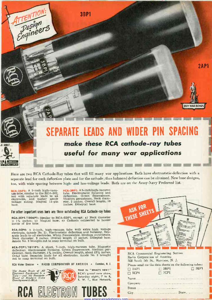
SEPARATE LEADS AND WIDER PIN SPACING
make these RCA cathode-ray tubes useful for many war applications
LMINI Mil _-®® all ,IlI111111r-1111111111 11111111r..I-J Here are two RCA Cathode -Ray tubes that will fill many war applications. Both have electrostatic -deflection with a
separate lead for each deflection plate and for the cathode ; thus balanced deflection can be obtained. New base designs,
too, with wide spacing between high- and low -voltage leads. Both are on the Army -Navy Preferred list.
RCA-2AP1: A 2 -inch high -vacu- um tube, similar to the RCA -902, but with separate leads to all electrodes, and higher anode voltage rating. Magnai 11 -pin base.
RCA -38P1: A 3 -inch high -vacuum tube. Electrostatic focusing and deflection. Green fluorescence. Medium persistence. Neck diam- eter, 2 inches. Overall length, 10 inches. Diheptal base.
For other important uses here are three outstanding RCA Cathode-ray tubes
RCA-3EP1/1806P1: Similar to RCA-3BP1, except: a) Neck diameter is 1" inches: b) Magnai base; e) Cathode connected to heater inside of the tube.
RCA-5CP4: A 5 -inch, high -vacuum tube with extra high voltage electrode, (anode No. 3). Electrostatic deflection and focusing. Sep- arate leads to all electrodes. White fluorescence. Medium persistence. Neck diameter, 2 inches. Overall length 17 inches. Diheptal base. Anode No. 3 brought out to snap terminal on bulb_
RCA-7CP1/1811P1: A short, 7 -inch, high -vacuum tube. Magnetic deflection. Electrostatic focusing. Green fluorescence. Medium per- sistence. Neck diameter, 1% inches. Overall length, about 131/2 inches. Octal base. Separate leads for all electrodes. Anode No. 2 brought out to snap terminal on bulb.
RCA Victor Division RADIO CORPORATION OF AMERICA Camden, N. J.
The Magic Brain of All Electronic Equipment Is a Tube - and the Fountain - Head of Modern Tube Development Is RCA.
TUNE IN "WHAT'S NEW?" RCAs great new show, Saturday nights, 7 to 8, E. W. T., Blue Network.
9
;;;J:
1?c
RCA Commercial Engineering Section Radio Corporation of America 508 South 5th St., Harrison, N. J. Please send me the data sheets on the following tubes:
2AP1 D 3BP1 3EP1
5CP4 7CP1
Name
Company
RCA 1 TUBES ' Street '
City State
www.americanradiohistory.com
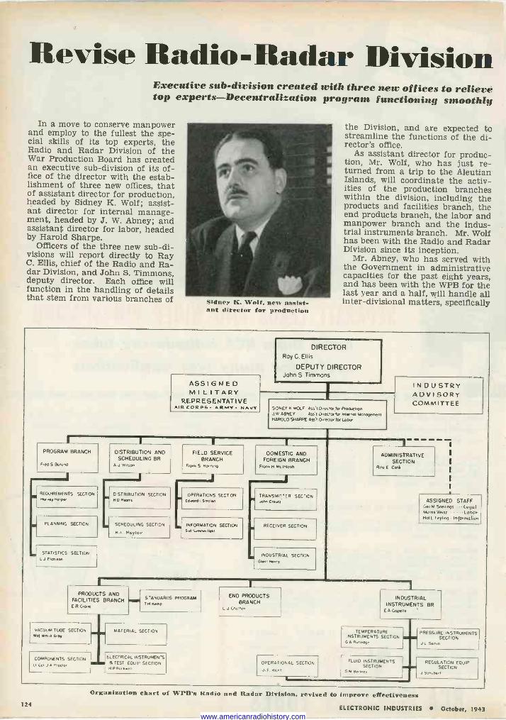
Revise Radio -Radar Division Executive sub -division created with three new offices to relieve top experts-Decentralization program functioning smoothly
In a move to conserve manpower and employ to the fullest the spe- cial skills of its top experts, the Radio and Radar Division of the War Production Board has created an executive sub -division of its of- fice of the director with the estab- lishment of three new offices, that of assistant director for production, headed by Sidney K. Wolf; assist- ant director for internal manage- ment, headed by J. W. Abney; and assistant director for labor, headed by Harold Sharpe.
Officers of the three new sub -di- visions will report directly to Ray C. Ellis, chief of the Radio and Ra- dar Division, and John S. Timmons, deputy director. Each office will function in the handling of details that stem from various branches of Sidney K. Wolf, nest assist-
ant director for production
the Division, and are expected to streamline the functions of the di- rector's office.
As assistant director for produc- tion, Mr. Wolf, who has just re- turned from a trip to the Aleutian Islands, will coordinate the activ- ities of the production branches within the division, including the products and facilities branch, the end products branch, the labor and manpower branch and the indus- trial instruments branch. Mr. Wolf has been with the Radio and Radar Division since its inception.
Mr. Abney, who has served with the Government in administrative capacities for the past eight years, and has been with the WPB for the last year and a half, will handle all inter -divisional matters, specifically
ASSIGNED MILITARY
REPRESENTATIVE AIR CORPS ARMY. NAVY
DIRECTOR Roy G Ellis
DEPUTY DIRECTOR John S Timmons
SIDNEY n WOLF Assl Dnec,e 1a Prod.clan J W ABNEY AMI Dlrecta for Internal Monogeonenl HAROLD SHARPE Asst (hector for Lobe
INDUSTRY ADVISORY COMMITTEE
PROGRAM BRANCH
Fred S Boland
REQUIREMENTS SECTION ,tar At, Harper
PLANNING SECTION
STATISTICS SECTION L J EICnlson
DISTRIBUTION AND SCHEDULING BR.
A J Wilson
DISTRIBUTION SECTION H G R.arns
SCHEDULING SECTION
H.L. NaTlo.
FIELD SERVICE BRANCH
Fronk S Normaa
1
OPERATIONS SECTION Ed.edI Smolt.,
INFORMATION SECTION Sod Summer1 WO
DOMESTIC AND FOREIGN BRANCH
Fronk H MCInlo$tl
TRANSMITTER SECTION John Cr.utt
RECEIVER SECTION
I INDUSTRIAL SECTION Glenn l4«,
ADMINISTRATIVE
SECTION Rtto E Cot!
PROOUCTS AND FACILITIES BRANCH
E R Gone
VACUUM TUBE SECTION Mal Wm A Goat
COMPONENTS SECTION LI Co, J A Proctor
STANDARDS PROGRAM 1
H nemo
MATERIAL SECTION
END PRODUCTS BRANCH
L J Dunen
OPERATIONAL SECTION
J.E. Har,
MIA
ASSIGNED STAFF GeoM SnellIngs legal Maras We15t . Labor Hal E Ferbnq - Information
INDUSTRIAL INSTRUMENTS BR
E A Capelle
TEMPERATURE INSTRUMENTS SECTION
G A Polleage
FLUID INSTRUMENTS SECTION
G M Berole,
PRESSURE INSTRUMENTS SECTION
J L 5..,,11
REGULATION EQUIP SECTION
J SCnub.rl
124
Organization chart of \"PR's Radio and Radar Division, revised to improve effectiveness
ELECTRONIC INDUSTRIES October, 1943 www.americanradiohistory.com
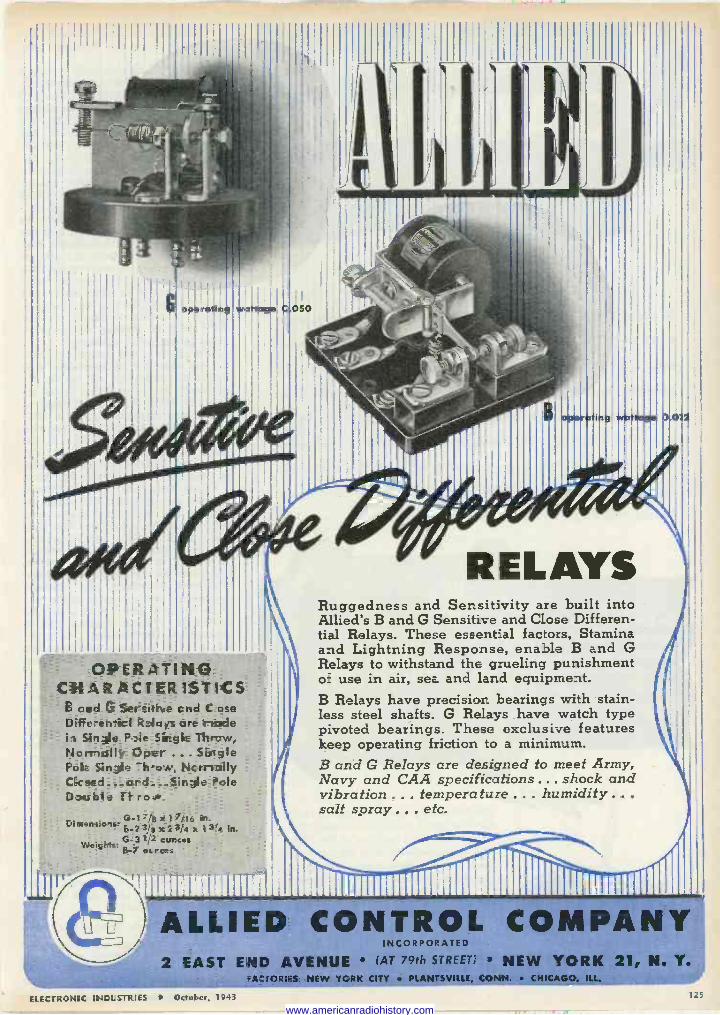
OPERATING CHARACtERISTICS
and ('s SereitiNe cnd C ose Diffe-enicI Relays are r-Ip.de i Single Paie Single Threw, Normally Oper ... Single Pole Single -h-oA., Ncrnally Ckssd PMe Datlhle, irFro.'.
Ci.nere,io.: G-17/8 x ` 7; 16 in- 5-2 ??I x 2 3l4 x 1 3Q 0-31;'2 ounces Weicle E-7 oa.res:
R E L AYS Ruggedness and Sensitivity are built into Allied's B and G Sensitive and Close Differen- tial Relays. These essential factors, Stamina and Lightning Response, enable B and G Relays to withstand the grueling punishment of use in air, sea and land equipment. B Relays have precision bearings with stain- Iess steel shafts. G Relays have watch type pivoted bearings. These exclusive features keep operating friction to a minimum. B and G Relays are designed to meet Army, Navy and CAA specifications ... shock and vibration ... temperature ... humidity .. .
salt spray .. , etc.
--ALLIED CONTROL COMPANY INCORPORATED
2 EAST END AVENUE (AT 79th STREET; NEW YORK 21, N. Y.
ELEZriZSTNrC INGI:STRIES ' Octot,cr, 1943
FA:roRnES: NEW YORK CITY PLANTSVILLE, CONN. CHICAGO, ILL.
www.americanradiohistory.com
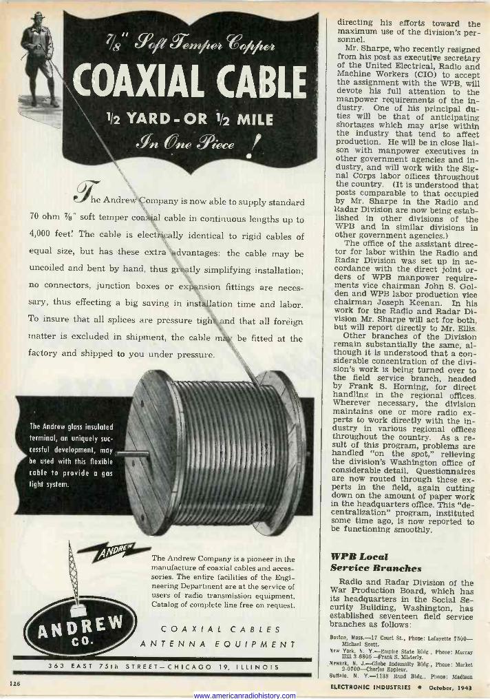
1/2 YARD -OR 1/2 MILE
gn Vne Mece
U C. he Andrew Company is now able to supply standard
70 ohm 7/s" soft temper coal cable in continuous lengths up to
4,000 feet! The cable is elect''cally identical to rigid cables of
equal size, but has these extra advantages: the cable may be uncoiled and bent by hand, thus greatly simplifying installation;
no connectors, junction boxes or exnsion fittings are neces- sary, thus effecting a big saving in insulation time and labor.
To insure that all splices are pressure tigh and that all foreign
matter is excluded in shipment, the cable m' be fitted at the
factory and shipped to you under pressure.
The Andrew glass insulated
terminal, cn uniquely suc-
cessful development, may
be used with this flexible
cable to provide a gas
tight system.
The Andrew Company is a pioneer in the manufacture of coaxial cables and acces- sories. The entire facilities of the Engi- neering Department are at the service of users of radio transmission equipment. Catalog of complete line free on request.
COAXIAL CABLES ANTENNA EQUIPMENT
363 EAST 75th STREET-CHICAGO 19, ILLINOIS
126
directing his efforts toward the maximum use of the division's per- sonnel.
Mr. Sharpe, who recently resigned from his post as executive secretary of the United Electrical, Radio and Machine Workers (CIO) to accept the assignment with the WPB, will devote his full attention to the manpower requirements of the in- dustry. One of his principal du- ties will be that of anticipating shortages which may arise within the industry that tend to affect production. He will be in close liai- son with manpower executives in other government agencies and in- dustry, and will work with the Sig- nal Corps labor offices throughout the country. (It is understood that posts comparable to that occupied by Mr. Sharpe in the Radio and Radar Division are now being estab- lished in other divisions of the WPB and in similar divisions in other government agencies.)
The office of the assistant direc- tor for labor within the Radio and Radar Division was set up in ac- cordance with the direct joint or- ders of WPB manpower require- ments vice chairman John S. Gol- den and WPB labor production vice chairman Joseph Keenan. In his work for the Radio and Radar Di- vision Mr. Sharpe will act for both, but will report directly to Mr. Ellis.
Other branches of the Division remain substantially the same, al- though it is understood that a con- siderable concentration of the divi- sion's work is being turned over to the field service branch, headed by Frank S. Horning, for direct handling in the regional offices. Wherever necessary, the division maintains one or more radio ex- perts to work directly with the in- dustry in various regional offices throughout the country. As a re- sult of this program, problems are handled "on the spot," relieving the division's Washington office of considerable detail. Questionnaires are now routed through these ex- perts in the field, again cutting down on the amount of paper work in the headquarters office. This "de- centralization" program, instituted some time ago, is now reported to be functioning smoothly.
WPB Local Service Branches
Radio and Radar Division of the War Production Board, which has its headquarters in the Social Se- curity Building, Washington, has established seventeen field service branches as follows: Boston, Mass. -17 Court St., Phone: Lafayette 7500-
Michael Scott. New York, N. Y.-Empire State Bldg., Phone: Murray
Hill 3 -6805 --Frank S. Misterly. Newark, N. J.-Globe Indemnity Bldg., Phone: Market
2 -0700 -Charles Eppleur. Buffalo, N. Y.-1138 Rand Bldg., Phone: Madison
ELECTRONIC INDUSTRIES October, 1943 www.americanradiohistory.com
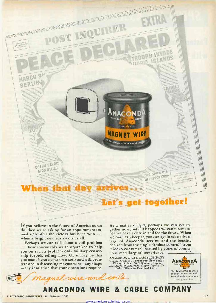
>. .,,.--...,".
If you believe in the future of America as we do, then we're asking for an appointment im- mediately after the victory has been won .. .
when a bright new era awaits us all. Perhaps we can talk about a coil problem
... how thoroughly we're organized to help you on such a problem only military censor- ship forbids telling now. Or it may be that you manufacture your own coils and will be in- terested in discussing magnet wire-any shape -any insulation that your operations require.
:t's_get- fogëf.. er ! As a matter of fact, perhaps we can get to- gether now, but if it happens we can't, remem- ber we have a date in and for the future. When we both can keep it, you can again take advan- tage of Anaconda service and the benefits derived from the single product control "from mine to consumer" backed by years of contin- uous metallurgical experience 4323E
ANACONDA WIRE & CABLE COMPANY General Offices: 25 Broadway,New York 4
Chicago Office: 20 N.Wacker Drive 6 Subsidiary of Anaconda Copper Mining Co.
Sales Offices in Principal Cities This familiar trade -mark symbolizes the best ef- forts of modern research
and production.
ANACONDA WIRE & CABLE COMPANY ELECTRONIC INDUSTRIES October, 1943 127
www.americanradiohistory.com
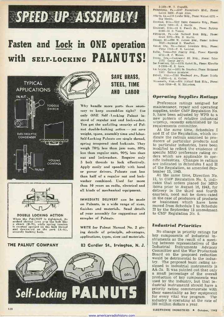
Fasten and Lock in ONE operation
with SELF-LOCKING PALNUTS!
TYPICAL
APPLICATIONS PALNUT
TOGGLE SWITCH
ELECTROLYTIC CONDENSER
VOLUME CONTROL
PALNUT
DOUBLE LOCKING ACTION When the PALNUT is tightened, its arched slotted jaws grip the bolt like a chuck (B -B), while spring tension is exerted upward on the bolt thread and downw,rd on the part (A -A), securely locking both.
THE PALNUT COMPANY
128
SAVE BRASS,
STEEL, TIME
AND LABOR
Why handle more parts than neces- sary to keep assemblies tight? Use only ONE Self - Locking Palnut in- stead of regular nut and lockwasher. You get the unfailing security of Pal - nut double -locking action - yet save weight, space, assembly time and labor. Self -Locking Palnuts are single thread, spring tempered steel locknuts. They weigh 70% less than jam nuts, 80% less than regular nuts, 90% less than nut and lockwasher. Require only 3 bolt threads to lock effectively. Apply easily and speedily with hand or power drivers. Palnuts cost less than half of a regular nut and lock - washer combined. Used for more than 10 years on radio, electrical and all kinds of mechanical equipment.
IMMEDIATE DELIVERY can be made on Palnuts, in a wide range of sizes, finishes and materials. Send details of your assembly for suggestions and samples of Palnuts.
WRITE for Palnut Manual No. 2 giv- ing details of principle, advantages, applications, types, sizes and materials.
83 Cordier St., Irvington. N. J.
Self -Locking PALNUTS
3-160-W. T. Croysdill. Philadelphia, Pa. -1617 Pennsylvania Blvd., Phone:
Locust 3400-Frank Aiken. Atlanta, Ga. -116 Candler Bldg., Phone: Walnut 4121-
Guy Mankin. Cleveland, Ohio -1317 Union Commerce Bldg., Phone:
Cherry 7900-11. J. Shartle. Cincinnati, Ohio -34 E. Fourth St., Phone: Parkway
0100-M. G. Thomas. Pittsburgh, Pa.-lst National Bank Bldg., Phone:
Grant 5370-Wm. IL Martin. Chicago, III. -226 W. Jackson Blvd., Phone: Andover
3600-Raymond ll. Woodford. Kansas City, Mo.-Mutual Interstate Bldg., Phone:
Victor 7780-F. Ii. Larrabee. Dallas, Texas -910 Fidelity Bldg., Phone: Riverside
5711-R. C. Watson. Denver, Colo.-Continental Oil Bldg., Phone: Tabor
3173-George Jos'yn. San Francisco, Cal. -1355 Market St., Phone: Klondike
2-2300-H. S. Ayers. Los Angeles, Cal. -1031 So. Broadway, Phone: Richmond
12G1-Herman Sehmleter. Detroit, Mich. -7310 Woodward Ave., Phone: Trinity
2-4900-L. A. Carbon. Minneapolis, Minn -334 Midland Bank Bldg., Phone:
Main 3244-11. M. Richardson.
Operating Supplies Ratings Preference ratings assigned for
maintenance, repair and operating supplies, under CMP Regulation No. 5, have been adjusted by WPB to a new pattern of relative industrial urgency, recently established by its requirements committee.
At the same time, Schedules I and II of the Regulation, which in- dicate the ratings assigned to pro- ducers of particular products and to particular industries, have been modified to reflect the existence of specific MRO preference rating or- ders which are applicable to spe- cific industries. Changes in ratings are indicated in Schedules I and II of the Regulation, as amended Sep- tember 13, 1943.
At the same time, Direction No. 12, to CMP Regulation No. 5, indi- cates that orders placed for MRO items prior to August 16, 1943, for delivery in the third and fourth quarters, need not be down -rated in the case of producers of products or businesses which have been moved from Schedule I to Schedule II by the September 13 amendment to CMP Regulation No. 5.
Industrial Priorities No change in priority ratings for
key components of industrial in- struments as the result of a meet- ing between representatives of the Industrial Instruments Advisory Committee and the War Production Board on the proposed reduction would be detrimental to the indus- try. The proposed basic rating as- signed to industrial instruments is AA -2x. It was pointed out that only a small percentage of the overall production of key components was used by the industry, but that in- dustrial instruments should have a priority rating commensurate with their essentiality as key equipment for every vital war program. The industry is operating at the rate of 200 million dollars a year. ELECTRONIC INDUSTRIES October, 1943
www.americanradiohistory.com
P-241
P-1921
il ,,1 11111.01(71 7"5"/
Closely
I(Ì13 1 h past twenty years,
( j lopm is to
1 (,i /o elec us comp other
/U ita ` enta during the
the leaders in
1%/ electronic
developments eve °Went par s
more
réa with many numerous anuf acture+ /r ment to prOv¡den + electronic
Closely simple to man ]
in today's í/ assign enta are job
it's been our
these ne is doing a
th ré1d any event, Always
i/r' applications.
Some of ent each ° built to e
intricate --in a day.
lent every 1/ ¡ntrica of our P
bemuse °
'cations roll out higher of
ARgGO parts to an even
,rhousandsds been improved m O'vewelcome
your inquiries.
slander e superior ecificaions
wartime sp stringent
PL,.68 P1756
P-1752
J-671
eW L 2 alte WC., ¿sic. 476 BROADWAY NEW YORK 13, N. Y.
JK-26
J-670
MANUFACTURERS OF SNORT WAVE TELEVISION RADIO SOUND EQUIPMENT
129 ELECTRONIC INDUSTRIES October, 1943
www.americanradiohistory.com
A Fast-GrowingCompany
Specializing in Electronics and having
A Proud War Production Record -- A Substantial Post -War Future and
A World -Wide Background of
Electronic Research and Development
invites additional applications e from technically trained
American citizens having the following basic qualifications:
Electronic Engineers-High calibre men with proven technical ability and a well-balanced background of acoustics, broadcasting, frequency modulation and ultra high frequencies. Opportunities exist in the research, designing, development and manufacturing of electronic products in general, particularly cathode ray, trans- mitting and special-purpose tubes; communications, electronic and precision test equipment.
Also an opportunity for a physio-chemist, preferably with elec- trochemical experience. Women with technical knowledge will be considered. In addition, applications are invited from technically experi- enced men with commercial qualifications:
Commercial Engineers-Several of these men required. Should have sound technical knowledge in communications, spe- cial device circuits, quartz crystal and electronic tube applications, with knowledge of quartz crystal and electronic tube manufac- turing processes.
Also one man who should have a background as metallurgist or physicist and preferably some practical experience with x-ray techniques.
Duties of Commercial Engineers will consist largely of personal contact and correspondence with engineering personnel among manufacturers of electrical and communications equipment, also with Government engineers.
If congenial association with a young and progressive organiza- tion fits in with long-range plans for your own future development and prosperity, let us hear from you now. Tell us your age and enough about your technical education and training, experience, draft status, availability and salary requirements to warrant an early interview in New York City, Dobbs Ferry or some mutually convenient point. A photograph will be appreciated. Address your letter in strict confidence to:
OFFICE OF THE PRESIDENT
NORTH AMERICAN PHILIPS COMPANY, INC. DOBBS FERRY, WESTCHESTER COUNTY, N. Y.
If you are now working in an essential industry at your highest skill, please do not apply.
Provide More Production For Test Equipment
To meet increasing requirements of the armed services for electronic test equipment, a plan for wider subcontracting of orders for critical test equipment, test instruments and component parts has been ini- tiated by the Radio and Radar Di- vision of the War Production Board.
Two surveys have been launched by the Radio and Radar Division in its plan to place this extra demand on the test equipment industry in places where facilities and compe- tent personnel already exist, since the expansion of facilities is im- practical for lack of time, construc- tion materials and new personnel.
Regional offices of WPB have been requested to furnish detailed reports on manufacturers and facil- ities available for prime or sub- contracts for producing test equip- ment, test instruments and com- ponents. At the same time, each manufacturer of electronic test equipment has been asked to indi- cate which firms would be most capable of adapting themselves to produce, under sub -contract, items for the manufacturer's schedule.
In a letter to manufacturers of electronic test equipment, Ray C. Ellis, Director of the Radio and Ra- dar Division, stated that the armed services have given notification that requirements for test equip- ment needed to manufacture, m - stall, maintain and service equip- ment for the future will increase substantially.
Tube Industry Model for Manpower Survey
The vacuum receiving tube in- dustry has been chosen as a guinea pig by the WPB Office of Labor Production for a survey of man- power problems. If a satisfactory procedure is attained in this study it will be extended to the entire electronics manufacturing field. The WPB officials said steps to combat turnover and absenteeism would include increased man- hours, day nurseries for women workers and assurance of adequate transportation facilities.
Blue's Key Station
When R'JZ transmitter finally is moved to its new location at Lodi, N. J., it will occupy this modern building, now under construction
130 ELECTRONIC INDUSTRIES October, 1943
www.americanradiohistory.com
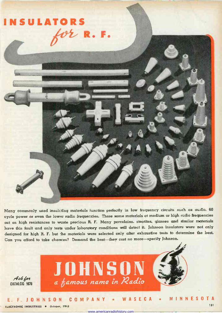
INSULATORS itie R. F.
Many commonly used insulating materials function perfe:tly in low frequency circuits s;c ì as at dio, 60
cycle power or even the lower radio frequencies. These same materials at medium or high radio frequencies
act as high resistances to waste precious R. F. Many porcelains, steatites, glasses and rimilar materials
have this fault and only tests under laboratory conditions will detect it. Johnson insulators were not only
designed for high R. F. but 'he materials were selected only after exhaustive tests to determine the best.
Can you afford to take chances? Demand the best-they cost no more-specify Johnson.
,itdl tv` CATALOG 9670 a 6am au name in Aaciio
E. F. JO H N SON COMPANY WASECA MINNESOTA ELECTRONIC INDUSTRIES October, 1943 131
.T www.americanradiohistory.com
Another exclusive Millen "Designed for Application" product. Combination high voltage terminal and Peru -bushing. Tapered contact pin Ms firmly into conical socket providing large area, low resistance con- nection. Pin is swivel mounted in cap to prevent twisting of lead wire. Easy to use. 1/4" o.d. insulation high voltage cable fits into opening in cap. Bared conductor passes Ihrs, pin for easy soldering to pre -tinned tip of contact plug.
e Standard 37001 available in either black or red bakelite. No. 37501 is low loss mica filled yellow bakelite for R.F. applications.
JAMES MILLEN MFG. CO., INC.
MAIN OFFICE AND FACTORY
MALDEN MASSACHUSETTS
Proposals for Uniform Contract Termination Dr. Teele outlines problems and analyzes suggested plans for prompt payments to contractors
One of the most significant re- cent pronouncements in regard to the orderly demobilization of in- dustry when war contracts are ter- minated was an address in Chicago by Dr. Stanley F. Teele, Deputy Director of the War Production Board Procurement Policy Division in which he stressed that the gov- ernment should develop and get into operation in the most expe- ditious possible manner machinery designed to assure "quick cash" payments prior to final settlement. Dr. Teele stated that the present policy of the Army and Navy in respect to prompt partial payment on terminated war contracts con- tained a primary difficulty in con- netcion with the hesitancy of contracting officers to approve pay- ment without convincing and con- clusive evidence to support any conclusion that the amount paid is "clearly within the amounts due."
The WPB official proposed that the related issues of prompt ter- mination of contracts and financial compensation to workers who are laid off should be given serious con- sideration, both within the govern- ment and outside, to provide uni- form and matured conclusion when the time comes for the termination of war production.
Pay all costs
On most of the important policy issues regarding the termination of war contracts judgments have not yet been crystalized and decisions have not yet been made, Dr. Teele noted, but he gave encouragement to industry, "that there is every intention within the government to work out these problems as rapidly and with as much wisdom as pos- sible." He added that he could state emphatically that he knew of no policy -making official in the War and Navy departments who "does not subscribe wholeheartedly" to the intention to reimburse the contractor for all costs incurred and all commitments entered into in good faith for the performance of a contract.
He pointed out that industry should observe closely the situation and watch for the proposed uni- form termination regulations now being framed by the armed ser- vices. He outlined the three prin- cipal proposals which have thus far emerged-advanced payments, loan, and purchase by the government of the rights of sub -contractors. He reviewed the bill of Senator Murray of Montana to provide that every
federal procurement agency shall within thirty days after the filing of a demand by the contractor, pay the latter not less than 75 per cent of the amount certified by him as due on the contract with both prime and sub -contractors being covered and the balance to be returned with interest at 5 per cent. The second plan is the establishment of a sys- tem of loans or guarantees of loans along the lines of the present V loans through local financial in- stitutions and Dr. Teele felt that such a program is desirable and can be administered in such a way as to be not at all consistent with the plan for mandatory advanced pay- ments on certification.
Quick payments The third proposal seeks to meet
two related objectives-quick pay- ments to sub -contractors and assur- ance to sub -contractors that their claims will be paid even if their customer (a prime contractor) be- comes insolvent. This proposal is that the government be authorized by legislation to purchase the rights of sub -contractors against their customers, up to a limit of 90 per cent of the estimated value of the rights prior to final proof of the claim with 100 per cent after the rights have been proved. Under this latter proposal the sub -con- tractor would take his chances on payment by the customer but would have the opportunity to se- cure payment from the government if the customer became insolvent.
Funds for workers It was pointed out that the dol-
lar volume of war production now running at approximately 100 bil- lion a year, is represented by a quarter of a million prime contracts and many million sub -contracts. Besides the "quick cash" problem for the contractors and sub -con- tractors, Dr. Teele stressed as a second problem that funds must be provided for workers laid off after termination of war contracts during a period when concerns will be struggling with the physical conversion of their plants for ci- vilian production and planning of sales and distribution organizations and relationships.
A third problem is the prompt removal from plants of raw mate- rials, work in process, finished goods and machinery no longer needed because of termination of contracts so as to not hamper con- version to civilian work. In addi- tion there are the grave issues of the disposal of surplus property without adversely affecting the markets and employment.
www.americanradiohistory.com
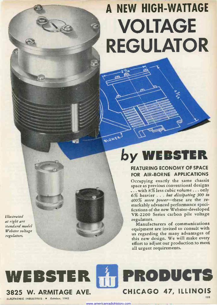
Illustrated at right are standard model Webster voltage regulators.
A NEW HIGH -WATTAGE
VOLTAGE REGULATOR
by WEBSTER FEATURING ECONOMY OF SPACE
FOR AIR -BORNE APPLICATIONS Occupying exactly the same chassis space as previous conventional designs ... with 8 % less cubic volume ... only 6% heavier ... but dissipating 300 to 400% more power-these are the re- markably advanced performance speci- fications of the new Webster -developed VR -2200 Series carbon pile voltage regulators.
Manufacturers of communications equipment are invited to consult with us regarding the many advantages of this new design. We will make every effort to adjust our production to meet all urgent requirements.
WEBSTER PRODUCTS 3825 W. ARMITAGE AVE. CHICAGO 47, ILLINOIS ELECTRONIC INDUSTRIES October, 1943 133
www.americanradiohistory.com
WASHINGTON Latest Electronic News Developments Summarized
by Electronic Industries' Washington Bureau * * *
LONG WAY TO GO-The newspaper stories about cancellations and terminations of war production do not apply to the electronic and radio manufacturing industries. Manufacturers in our field can plan for their work on the basis of the global war. When the European phase of the war is over, the Army's require- ments may well fall off to some extent as the concen- tration of the United Nations' attack is turned against the Japanese in the Pacific. But then the Navy's needs for electronic and radio equipment will be uppermost. The transition to civilian production can be imple- mented in an orderly way in such a situation when the Army's requirements begin to slacken off. Right now practically all of the major electronic -radio com- panies are booked to the hilt in war production.
HIGHER GAINS NEEDED-The increases in pro- duction both for the Army Signal Corps and the Navy's Radio Division of its Bureau of Ships have been most gratifying in the past two months. Substantial in- creases still face the manufacturers before the peak production necessary to comply with the requirements of the armed services. Under the leadership of Major General William H. Harrison, Chief of the Signal Sup- ply Services, the Signal Corps in September recorded a continued increase in the neighborhood of 10 per cent over the preceding month, while August was 6 per cent above July and the latter month 17-18 per cent over June.
PEAK MONTHS OFF-But unless the rate of in- crease is sharply accelerated, the needed peak of pro- duction to meet the 1943-44 requirements appears several months off. The Navy's Radio Division under Captain Jennings B. Dow has achieved a 50 per cent rise in monthly production, in comparison with last January. But it needs an increase of practically 50 per cent all through 1944 to meet its requirements- and for the anticipated fighting against Japan both in electronic and radio equipment on ships and Naval planes, the step-up in production is vital.
CHANGES IN NAVY'S RADIO DIVISION-In line with the traditional desire of a Navy officer to go to sea, Captain A. M. Granum, USN, who has most suc- cessfully directed the Radio Division's Installation and Maintenance Branch since November 1, 1942, during the entire administration of Captain Dow, has just been ordered to an important foreign sea duty assignment. He is succeeded by Commander E. L. Fryberger, USN, who has been the Assistant for Ships in that branch for the past few months. Commander S. A. Shephard, USN, is now the Assistant for Ships. Comdr. H. C. Owen, USN, in charge of the Aircraft Radar Section of the Design Branch, also has received his sea duty orders and has been replaced by Comdr. J. F. Mullen, Jr. All these officers are exceptionally 134
qualified in Naval communications and radio procure- ment with many assignments in radio work both on shore and with the fleet and through their post- graduate studies in communications and radio.
POSTWAR PROSPECTS-The U. S. Chamber of Commerce survey of consumer postwar needs within six months after peace comes brought forth the fore- cast that 2,555,000 families intended to buy radio re- ceiving sets. . . . The School of the Air is certain to grow, with much apparatus to be distributed to edu- cational institutions; FCC Chairman James Lawrence Fly predicts that hundreds of FM stations for educa- tional use can be established on the five FM channels already set aside for that purpose and undoubtedly under the new radio developments educational radio will have a much larger portion of the spectrum... .
While nothing concrete has yet been decided, the FCC Engineering Department's allocation committee has been making considerable progress on the collection of the basic and essential information for such a step.
SIGNAL CORPS DECENTRALIZATION-The decen- tralization of the Army Signal Corps operations in procurement has now been practically completed with the three field procurement districts having the re- sponsibility for the placement of contracts and the following up of production. The Procurement Districts are Philadelphia under the command of Col. E. V. Elder; Monmouth under Col. Van Ness Phillips; and, Dayton under the command of Col. W. J. Daw. In the following up of production the Procurement Dis- tricts will work in the closest sort of coordination and cooperation with the Army -Navy Electronics Produc- tion Agency.
ANEPA STATUS-The status of ANEPA has not been changed and it will continue the activities which have been so beneficial to the entire Signal Corps pro- curement program. The Procurement Districts will concentrate their production follow-up efforts with the prime contractors and ANEPA will center its func- tioning more with the component manufacturers and sub -contractors. In the War Department headquar- ters of the Signal Supply Services, General Harrison has brought in Col. William M. Mack, Procurement Officer of the Wright Field, Dayton, Procurement Dis- trict to head the Procurement Division. Col. Glenn L. Palmer, who has been acting chief of that Division, is now directing the new Requirements Division which was split off from the Procurement Division.
MISCELLANEOUS-WPB Radio & Radar Division's field office set-up is a guidepost for the current WPB decentralization plan. . . . Civilian tube production under Frank McIntosh's direction now is averaging 1,500,000 receiver tubes monthly.
ELECTRONIC INDUSTRIES October, 1943
www.americanradiohistory.com
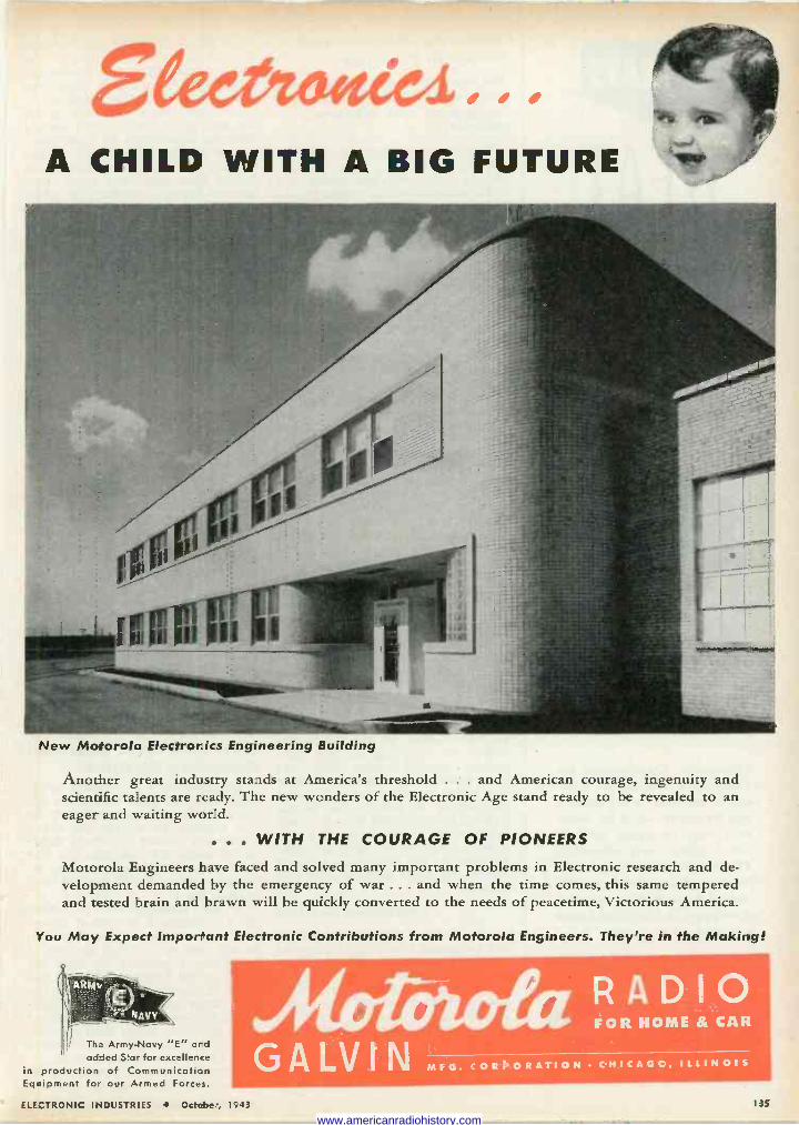
1 l
/ /
A CHILD WITH A BIG FUTURE
New Motorola Electronics Engineering Building
Another great industry stands at America's threshold . . . and American courage, ingenuity and scientific talents are ready. The new wonders of the Electronic Age stand ready to be revealed to an eager and waiting world.
... WITH THE COURAGE OF PIONEERS
Motorola Engineers have faced and solved many important problems in Electronic research and de- velopment demanded by the emergency of war ... and when the time comes, this same tempered and tested brain and brawn will be quickly converted to the needs of peacetime, Victorious America.
You May Expect Imporffant Electronic Contributions from Motorola Engineers. They're in the Making!
The Army -Navy "E" and added Star for excellence
in production of Communication Equipment for our Armed Forces.
AiOrOtaa RADIO FOR HOME & CAR
GALVIN MFG. CORPORATION CHICAGO, ILLINOIS
ELECTRONIC INDUSTRIES October, 1943 135
www.americanradiohistory.com
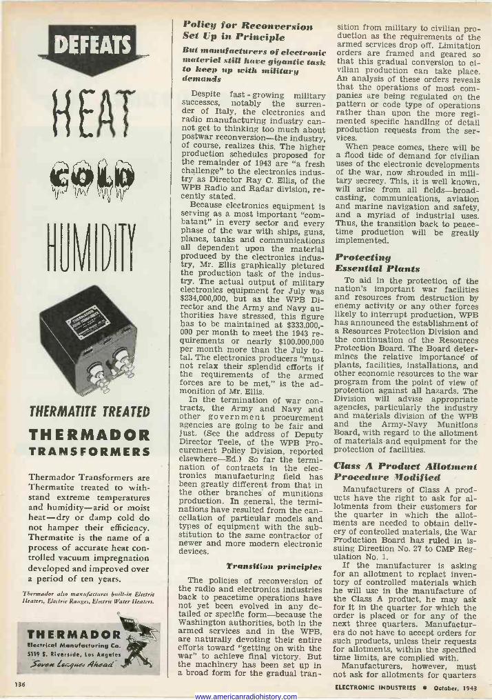
H EAT
eee HUVWTÏ
THERMATITE TREATED
THERMADOR TRANSFORMERS
Thermador Transformers are Thermatite treated to with- stand extreme temperatures and humidity-arid or moist heat-dry or damp cold do not hamper their efficiency. Thermatite is the name of a process of accurate heat con- trolled vacuum impregnation developed and improved over a period of ten years.
Thermador also manufactures built-in Electric Heaters, Electric Ranges, Electric Water Heaters.
THERMADOR Electrical Manufacturing Co.
5119 S. Riverside, Los Angeles S ve« 144.9.4e4 Ahead"
136
Policy for Reconversion Set Up in Principle But manufacturers of electronic materiel still hare gigantic task to keep up with military demands
Despite fast - growing military successes, notably the surren- der of Italy, the electronics and radio manufacturing industry can- not get to thinking too much about postwar reconversion-the industry, of course, realizes this. The higher production schedules proposed for the remainder of 1943 are "a fresh challenge" to the electronics indus- try as Director Ray C. Ellis, of the WPB Radio and Radar division, re- cently stated.
Because electronics equipment is serving as a most important "com- batant" in every sector and every phase of the war with ships, guns, planes, tanks and communications all dependent upon the material produced by the electronics indus- try, Mr. Ellis graphically pictured the production task of the indus- try. The actual output of military electronics equipment for July was $234,000,000, but as the WPB Di- rector and the Army and Navy au- thorities have stressed, this figure has to be maintained at $333.000,- 000 per month to meet the 1943 re- quirements or nearly $100,000,000 per month more than the July to- tal. The electronics producers "must not relax their splendid efforts if the requirements of the armed forces are to be met," is the ad- monition of Mr. Ellis.
In the termination of war con- tracts, the Army and Navy and other government procurement agencies are going to be fair and just. (See the address of Deputy Director Teele, of the WPB Pro- curement Policy Division, reported elsewhere-Ed.) So far the termi- nation of contracts in the elec- tronics manufacturing field has been greatly different from that in the other branches of munitions production. In general, the termi- nations have resulted from the can- cellation of particular models and types of equipment with the sub- stitution to the same contractor of newer and more modern electronic devices.
Transition principles The policies of reconversion of
the radio and electronics industries back to peacetime operations have not yet been evolved in any de- tailed or specific form-because the Washington authorities, both in the armed services and in the WPB, are naturally devoting their entire efforts toward "getting on with the war" to achieve final victory. But the machinery has been set up in a broad form for the gradual tran-
sition from military to civilian pro- duction as the requirements of the armed services drop off. Limitation orders are framed and geared so that this gradual conversion to ci- vilian production can take place. An analysis of these orders reveals that the operations of most com- panies are being regulated on the pattern or code type of operations rather than upon the more regi- mented specific handling of detail production requests from the ser- vices.
When peace comes, there will be a flood tide of demand for civilian uses of the electronic developments of the war, now shrouded in mili- tary secrecy. This, it is well known, will arise from all fields-broad- casting, communications, aviation and marine navigation and safety, and a myriad of industrial uses. Thus, the transition back to peace- time production will be greatly implemented.
Protecting Essential Plants
To aid in the protection of the nation's important war facilities and resources from destruction by enemy activity or any other forces likely to interrupt production, WPB has announced the establishment of a Resources Protection Division and the continuation of the Resources Protection Board. The Board deter- mines the relative importance of plants, facilities, installations, and other economic resources to the war program from the point of view of protection against all hazards. The Division will advise appropriate agencies, particularly the industry and materials division of the WPB and the Army -Navy Munitions Board, with regard to the allotment of materials and equipment for the protection of facilities.
Class A Product Allotment Procedure Modified
Manufacturers of Class A prod- ucts have the right to ask for al- lotments from their customers for the quarter in which the allot- ments are needed to obtain deliv- ery of controlled materials, the War Production Board has ruled in is- suing Direction No. 27 to CMP Reg- ulation No. 1.
If the manufacturer is asking for an allotment to replact inven- tory of controlled materials which he will use in the manufacture of the Class A product, he may ask for it in the quarter for which the order is placed or for any of the next three quarters. Manufactur- ers do not have to accept orders for such products, unless their requests for allotments, within the specified time limits, are complied with.
Manufacturers, however, must not ask for allotments for quarters ELECTRONIC INDUSTRIES October, 1943
www.americanradiohistory.com
In the excitement of electronic discoveries and predictions, one great and im-
portant factor-the human element-stands forlorn. Machines and uses are, after
all, only the offspring of man's experience and ingenuity. The more capable the
man, the more dependable his product.
This is the human element upon which the Electronic Corporation of America
places a high evaluation. And this, we suggest, is the element you should seek
when planning your future program. Find out more about your man and his back-
ground. Is he an old-timer or a 'war baby"? Does he have the ability and facilities to produce? How high are his standards? These are questions we'll gladly answer.
We're 100% in war work now ... but, occasionally production schedules enable us
to accept additional contracts ... communicate with us.
A CALL FOR GREATER EFFORT... The WPB reports that war production has
fallen off considerably. This is a challenge to industry and labor, and it's up to us to find the reason, whether it be optimism, internal strife, working conditions, discrimination, etc.
The roar of battle is thousands of miles away, but, if you listen closely, you can hear the screams of a dying soldier. Can it be because we failed him?
ELECTRONIC CORP. OF AMERICA 45 WEST 18th STREET NEW YORK II, N.Y. WATKINS 9-1870
ELECTRONIC INDUSTRIES October, 1943 I3" www.americanradiohistory.com
PermoFlux Enaireers, through -he coi -rol any
developmrn- of new techniques, have literati!, toried heodphone per-
formance froth the laboratory rig it in -c the battle aria; ihemse tees. The extra sensitivity, with freqt oncy response and high overall cperaing efficiency ow Permoflux Dy -gamic Headphones mcke possible imprTved intelligibility of v tel messages uncer the rnos- advers, noie level conditions. Tc day -hey are help r g our boys win V cot, - tcrnorrow they w 11
be available to cl.
Back the Attack with WAR BONDS!
CORPORATION 4916-22 W. Grand Ave., Chicago, III.
PIONEER MANUFACTURERS QI PERMANENT MAGNET DYNAMIC TRANSDUCERS
in which they cannot accept de- livery of controlled materials be- cause of inventory limitations.
Interpretation No. 11 to CMP Regulation No. 1 indicates that a manufacturer of Class A products must fill orders out of excess stocks if the size of his inventory prohib- its acceptance of delivery of con- trolled materials. Nevertheless a manufacturer may insist on an al- lotment before accepting an order for a Class A product, if the quar- ter for which he is seeking the allotment is within the time limit permitted by Direction No. 27.
Four procedures Manufacturers of Class A prod-
ucts operating under the Controlled Materials Plan may, instead of making allotments to their suppliers, follow any one of four procedures, if their suppliers consent, the War Production Board pointed out to- day. Such a manufacturer may use any one of the following alter- natives:
1. He may sell the material to his supplier from his own inventory.
2. He may furnish the material to his supplier on toll or processing agreement, retaining title in him- self.
3. He may place an authorized controlled material order for deliv- ery to himself and trans -ship the material to his supplier, either by sale or under toll or processing agreement.
4. He may place an authorized controlled material order for deliv- ery directly to his supplier.
Allotment records In none of these cases does the
customer make an allotment, and the supplier does not have to keep any allotment records. The sup- plier must, however, keep records to show that he is using the mate- rial for the purpose for which it was received.
Customers furnishing the mate- rial must include it in their own requirements in applying for allot- ments in the same way as if he were going to allot it. He may not furnish controlled material to his suppliers except under conditions where he would be able to make an allotment under the terms of CMP Regulation No. 1. Consequently, the four procedures may not be used to make allotments to pro- ducers of Class B products, unless special permission to do so is ob- tained from WPB, since under paragraph (g) of CMP Regulation No. 1, consumers may not make al- lotments to Class B product manu- facturers. Class B product pro- ducers ordinarily receive their allot- ment from WPB.
138 ELECTRONIC INDUSTRIES October, 1943
www.americanradiohistory.com
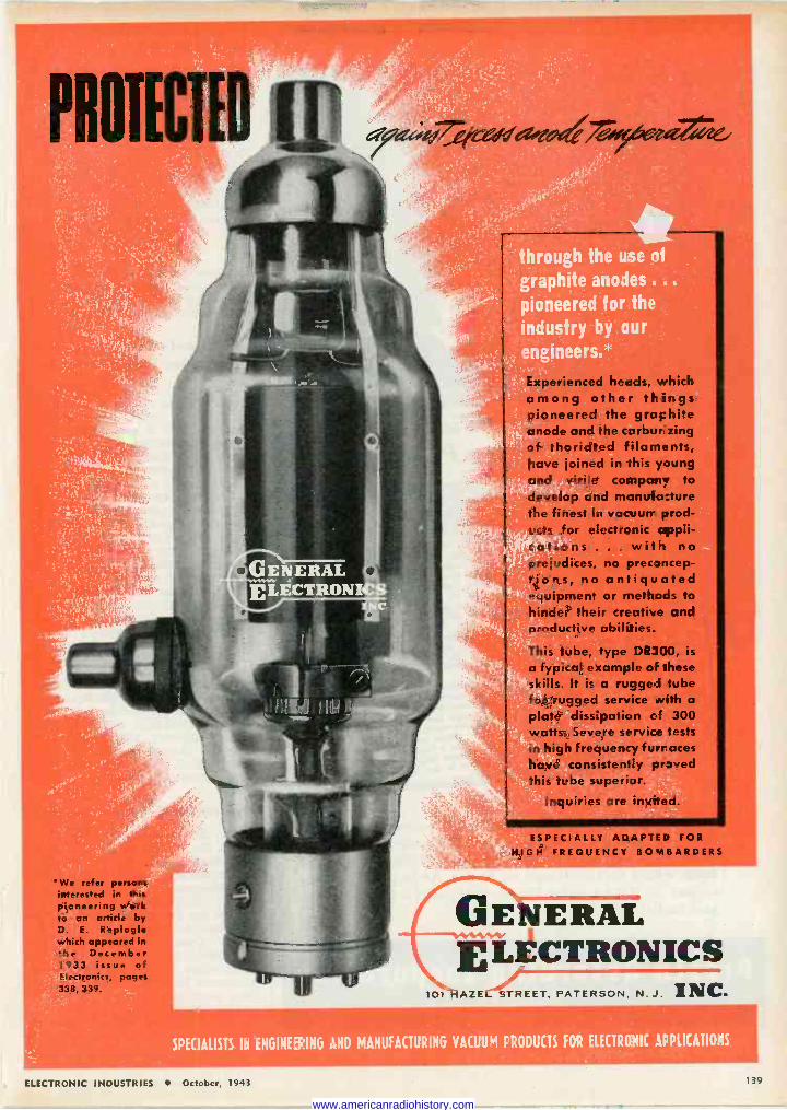
* We refer persons interested in this pioneering work to an article by D. E. Replogle which appeared in the December 1933 issue of Electronics, pages 338, 339.
GE E LÉCTRDNI
hróügh the use of
:graphite anodes .. .
pioneered for the
;industry by our engineers.*:
Axpeìienced heads, which among other things pioneered the graphite anode and the carbur zing of thoriated filaments, have joined in this young and virile company to develop and manuia:ture the finest in vacuums prod- ucts for electronic appli- cations . . . with no prejudices, no prec3ncep- tions, no antiquated equipment or methods to hinder their creative and productive abilities.
This tube, type DR300, is a typical example of these skills. It is a rugged tube for rugged service with a
plate dissipation of 300 watts. Severe service tests in high frequency furraces have consistently pr3ved this tube superior.
Inquiries are invited.
ESPECIALLY ADAPTED FOR HIGH FREQUENCY BOMBARDERS
GE ERAL E LÉCTRONICS
101 'A2:E STREET, PATERSON. N.J. INC.
SPECIALISTS IN ENGINEERING AND MANUFACTURING VACUUM PRODUCTS FOR ELECTRONIC APPLICATIONS
ELECTRONIC INDUSTRIES October, 1943 139
www.americanradiohistory.com
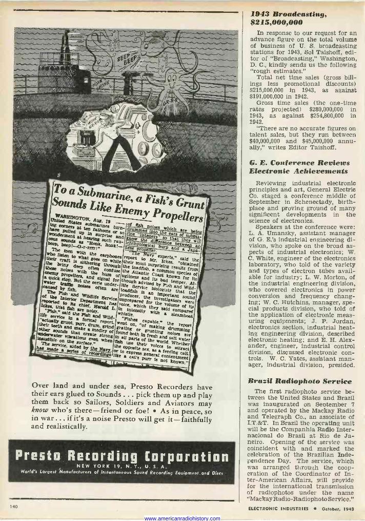
.,..,....:..._..
-,..-.......,_
' . . . ', ..... .'L1. -. - _. iwiii ww ' E5p sv ì g raari Q
T"`? ^^~ 3tr.,rxr.<.,.... . ,. .,---...
.,,,
wwYgiffl
s!"
',MM.,
41
ll.
..r
.3.;r07mpe., w°`k `°.$r^'r. my.!/,rï;lw`
n, ( C
i
GR.R R.
;:> i
-1......,
,.... .., . V- ¡V
--.....
ï<.
y.
.`-.- _ Sounds Submarine, a Fish's Grunt d Li ke Enemy
WASHINGTON.Dnited
Aug. 19 Propellers ma's esat
submarines turn- of fish noises which bare rners tCt n fathoms or a into tsoha are bein
honk!--
wondermentknow t ears of subma- cons anus* Au 1'
rand know the'listeners' that t e will an
The mar r mTb^
n prone er. D and taeJaPa-
to wlu
e who listen M slitheringg0ea
on whir theirrm s Mr. Ickes. ^ said
these noises riny deep often t ugh the toadfish.surprising common
sees dº f d ep f a
confuse the Atlantic C a knownfors of hum of uglinessoast for its ater the eerie under- life e advised by nd ILI
Fis a temper.
Wild-
a
by fish noises often are Service biologists wild- cy
is that ofd Ptah and Wlldllfe ProduC r the investigators lmportaat
Were
$: reverted
toff chior ief. has Vunpreparedi hfor said
volume compared
its Wit fiery are noisy.d L. in intensity wityh
life said the Ptah and Wild- whistle. am
gce runt. a forme report- went " capable.* the their teeth and
purr' dNm grind gratingon' "of antmaking report
are sounds a
make eraaa medlte y
of found both infres lag noise water 1e vibrations even when f
in all arta of thee their
and salt ëact
} The service.
ade afededrnederwiry th Na the °Merle sex, as attract
aeries of vet° ga ,1Ye ae cat's's general cot knoingwn."
Purr is not known,'
Over land and under sea, Presto Recorders have their ears glued to Sounds ... pick them up and play them back so Sailors, Soldiers and Aviators may know who's there-friend or foe! As in peace, so in war... if it's a noise Presto will get it-faithfully and realistically.
Presto Recording Corporation NEW YORK 19, N. Y., U. S. A.
World's Largest Manufacturers of Instantaneous Sound Recording Equipment and Discs
1943 Broadcasting, $215,000,000
In response to our request for an advance figure on the total volume of business of U. S. broadcasting stations for 1943, Sol Taishoff, edi- tor of "Broadcasting," Washington, D. C., kindly sends us the following "rough estimates."
Total net time sales (gross bill- ings less promotional discounts) $215,000,000 in 1943, as against $191,000,000 in 1942.
Gross time sales (the one-time rates projected) $280,000,000 in 1943, as against $254,800,000 in 1942.
"There are no accurate figures on talent sales, but they run between $40,000,000 and $45,000,000 annu- ally," writes Editor Taishoff.
G. E. Conference Reviews Electronic Achievements
Reviewing industrial electronic principles and art, General Electric Co. staged a conference middle of September in Schenectady, birth- place and proving ground of many significent developments in the science of electronics.
Speakers at the conference were: L. A. Umansky, assistant manager of G. E.'s industrial engineering di- vision, who spoke on the broad as- pects of industrial electronics; W. C. White, engineer of the electronics laboratory, who told of the variety and types of electron tubes avail- able for industry; L. W. Morton, of the industrial engineering division, who covered electronics in power conversion and frequency chang- ing; W. C. Hutchins, manager, spe- cial products division, who told of the application of electronic meas- uring equipments; J. P. Jordan, electronics section, industrial heat- ing engineering division, described electronic heating; and E. H. Alex- ander, engineer, industrial control division, discussed electronic con- trols. W. C. Yates, assistant man- ager, industrial division, presided.
Brazil Radiophoto Service The first radiophoto service be-
tween the United States and Brazil was inaugurated on September 7 and operated by the Mackay Radio and Telegraph Co., an associate of I.T.&T. In Brazil the operating unit will be the Companhia Radio Inter- nacional do Brasil at Rio de Ja- neiro. Opening of the service was coincident with and marked the celebration of the Brazilian Inde- pendence Day. The service, which was arranged through the coop- eration of the Coordinator of In- ter -American Affairs, will provide for the international transmission of radiophotos under the name "Mackay Radio -Radiophoto Service."
140 ELECTRONIC INDUSTRIES October, 1943
www.americanradiohistory.com
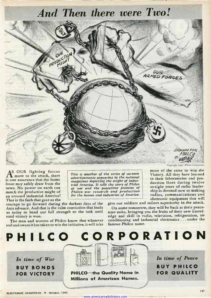
And Then there were Two!
r3+
AS OUR fighting forces move to the attack, there
is one assurance that the home front may safely draw from the news. No power on earth can match the productive might of an aroused industrial America! That is the faith that gave us the courage to go forward during the darkest days of the Axis advance. And that is the calm conviction that leads us today to bend our full strength to the task until total victory is won.
The men and women of Philco know that whatever toil and sweat it has taken to win the initiative, it will take
This is another of the series of cartoon advertisements appearing in the national magazines depicting the might of indus- trial America. It tells the story of Philco at war and the peacetime promise of Philco war research and production for the homes and industries of America.
/ji4WNfOl2
fJP/!/LCo ` 1 S
Copyright 943-Philco Corporation
more of the same to win the Victory. All they have learned in their laboratories and pro- duction lines during twelve straight years of radio leader- ship is devoted now to making radios, communications and electronic equipment that will
give our soldiers and sailors superiority in the attack. On some tomorrow, they will be back at their peace-
time tasks, bringing you the fruits of their new knowl- edge and skill in radio, television, refrigeration, air conditioning and industrial electronics ... under the famous Philco name.
PHILCO CORPORATION In time of War
BUY BONDS FOR VICTORY
-Th = o
111 PHILCO-the Quality Name in Millions of American Homes.
In time of Peace
BUY PHILCO FOR QUALITY
ELECTRONIC INDUSTRIES October, 1943 141
www.americanradiohistory.com
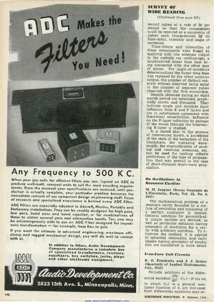
Any Frequency to 500 K C. When your job calls for efficient filters you can c'epend on ADC to produce well-built, compact units to suit the most exacting require- ments. From the moment your specifications are received, until pro- duction is actually complete, your particular problem becomes the immediate concern of our competent design engineering staff. Years of research and specialized experience is beriind every ADC Filter. ADC Filters are especially adapted to Aircraft, Marine, Portable and Stationary installations. They can be readily designed for high pass, low pass, band pass and band rejection, or for combinations of these to obtain several pass and attenuation bands. Too, you may be advantageously able to use an ADC Filter designed for imped- ance transformation - for example, from line to grid. If you want the ultimate in advanced engineering, maximum effi- ciency and rugged mechanical design, you will! do well to consult With us.
In addition to filters, Audio Development Company manufactures a complete line of specialized transformers, reactors, equalizers, key switches, jacks, plugs and other electronic equipment.
142
SURVEY OF WIDE READING
(Continued from page 107)
second pulses at a rate of 50 per second so that the components could be received as a succession of pulses each characterized by its time -delay, intensity and angle of incidence.
Time -delays and intensities of these components were found by applying only one antenna output to the cathode ray oscillograph, a synchronized linear time base be- ing connected with the other pair of plates. For angle -of -incidence determinations the linear time base was replaced by the other antenna output, the number of distinct sep- arate ellipses observed being equal to the number of separate pulses observed with the first connection.
Results obtained during an eight month period are tabulated, graph- ically shown and discussed. They indicate single and multiple layer reflection from E and F layers and are in satisfactory agreement with theoretical expectations. Influence on the F -layer reflection by passage of the waves through the interven- ing E -layer is studied.
It is stated that in the absence of intervening layers, a knowledge of the state of the ionization of the ionosphere, the operating wave- length, the characteristics of send- ing and receiving antennas, etc., can be used for making reliable predictions of the type of propaga- tion that may prevail in the case of short -distance short-wave prop- agation.
On Oscillations in Resonant Cavities M. M. Jouguet (Revue Generale de L'Electricite, Paris, Vol. 51, No. 6, 1942)
The mathematical problem of a resonant cavity bounded by a sur- face of revolution and consisting of a perfect conductor is treated. General solutions for geometrical- ly simple cavities are derived, as well as particular solutions having symmetry of revolution for a cav- ity with arbitrary meridian. To il- lustrate the method, it is applied to spherical resonators, and oscil- lations having symmetry of revolu- tion are considered in more detail.
Iron -Core Coil Circuits K. O. Friedrichs and J. J. Stoker (Quarterly of Applied Mathematics, July, 1943)
Periodic solutions of the differ - d2 ential equation- dt2 -f (.)= F cos wt,
in which f(s) is a general non- linear function of x, are discussed. Such differential equations may oc - ELECTRONIC INDUSTRIES October, 1943
www.americanradiohistory.com
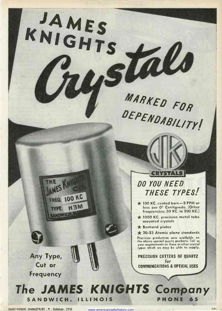
S TS
Any Type, Cut or
Frequency
ARKE0 FOR DEPEemBa/Tyl
t RYSTALS
DO YOU NEED THESE TYPES!
* 100 KC. coated bars -3 PPM or less per 0° Centigrade. (Other frequencies: 50 KC. to 200 KC.)
* 1000 KC. precision metal tube mounted crystals
* Bertrand plates
* 20-23 Atomic plane standards Precision production now available on the above special quartz products. Tell us
your requirements on these or other crystal types which we may be able to supply.
PRECISION CUTTERS OF QUARTZ
for COMMUNICATIONS & OPTICAL USES j
The JAMES KNIGHTS Company SANDWICH, ILLINOIS PHONE 65
ELECTRONIC INDUSTRIES October, 194: 141 www.americanradiohistory.com
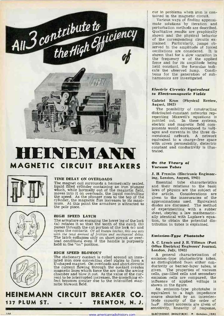
HEINEMANN MAGNETIC CIRCUIT BREAKERS
TIME DELAY ON OVERLOADS The magnet coil surrounds a hermetically sealed, liquid filled cylinder containing an iron plunger which, while normally out of the magnetic field, moves into it on overloads, the liquid controlling the speed. As the plunger rises to the top of the cylinder, the magnetic flux increases to its maxi- mum. At this point the armature is attracted to the pole piece.
HIGH SPEED LATCH The armature on engaging the lower leg of the lock (a) rotates it so that the tooth of the catch (b) passes through the cut portion of the lock (c) and opens the contacts. Of all known latches, this one acts with the least amount of friction and mechanical delay. The latch collapses only on short circuit or over- load conditions even if the handle is purposely held in the "on" position.
HIGH SPEED BLOWOUT The stationary contact is coiled around an insu- lated iron core connecting steel plates to form a U-shaped magnet. On overloads and short circuits the current flowing through the contact creates magnetic lines which force the arc into the arcing chamber and blow it out. As the value of the cur- rent to be interrupted increases, the quenching ef- fect becomes greater due to the intensified mag- netic blowout field.
HEINEMANN CIRCUIT BREAKER CO. 137 PLUM ST. - - - TRENTON, N. J.
cur in problems when iron is con- tained in the magnetic circuit.
Various ways of finding approxi- mate solutions by iteration and perturbation methods are described. Qualitative results are graphically shown and the physical behavior of the corresponding circuits ex- plained. Particularly, jumps ob- served in the amplitude of forced oscillations are considered. It is shown that for a slow variation in the frequency w of the applied force and for its amplitude being held constant, the formulas indi- cate the observed jump. Condi- tions for the generation of sub - harmonics are investigated.
Electric Circuits Equivalent to Electromagnetic Fields Gabriel Kron (Physical Review, August, 1943)
The possibility of constructing distributed -constant networks rep- resenting Maxwell's equations is pointed out. In these systems, electric and magnetic field com- ponents would correspond to volt- ages and currents in the three di- mensional network. A network equivalent to a charge -free space with given permeability, dielectric constant and conductivity is illus- trated.
On the Theory of Vacuum Tubes
J. H. Fremlin (Electronic Engineer- ing, London, August, 1943)
Essential tube characteristics and their relations to the basic laws of physics are the subject of the article. Considerations are given to the inaccuracies of the approximations used. Equivalent diodes are discussed. The method of experimenting with a rubber sheet, obeying a law mathematic- ally identical with Laplace's equa- tion, to obtain the potential dis- tribution in tubes is explained.
Emission -Type Phototube A. C. Lynch and J. R. Tillman (Post Office Electrical Engineers' Journal, London, July, 1943)
A general characterization of emission -type photoelectric tubes, as distinguished from either con- ductivity or barrier -layer tubes, is given. The properties of vacuum cells, gas -filled cells and secondary emission cells are compared; the influence of applied voltage is shown in the figure.
An emission -type phototube is equivalent to a high impedance source shunted by an interelec- trode capacity of the order of 5,µF. Short accounts are given of sensitivity, linearity of response,
144 ELECTRONIC INDUSTRIES October. 1943 www.americanradiohistory.com
Y ITQFO USEN^MEEE0 FIXED R E51510R5
Your "Answer Book" to Resistance Problems
Electronic Engineers everywhere have been using Ohmite Catalog "40" as their guide -book on resistance problems. They have found it an
indispensable source of information. Its 96 pages are packed full of
helpful engineering data, dimensional drawings, useful reference tables,
charts, and a manual of resistance measurements. Catalog "40" gives
details on the wide range of Ohmite types and sizes in resistors, rheostats
chokes, tap switches and attenuators ... both stock and special units... for all types of applications in the Armed Forces and in Industry.
Catalog "40" explaines how to select the right units for each need. It
can help you in designing new devices for a new tomorrow. Ohmite Engineers are glad to work with you.
OHMITE MANUFACTURING COMPANY 4984 Flournoy Street, Chicago 44, Illinois
o 1
SyFttCN
ONm'TE
OUS'NSMFt, ENFO5l4!
oaM1f .ow
!O SE[FC! A ;gMEOsrar
-+ . ti w.r,r .w..,.,
-»m... a.... ..
NOTE: If you do not already have Catalog and Engineering Manual No. 40, write forit today on company letterhead, It's free.
NO
oer cc
,VM
OHMITE-- ' TICS OE RISESroRS 45 HIGH ,IFEOUt
7C
O
AEs/sroRs
70 omitir
ELECTRONIC INDUSTRIES October, 1943 145
www.americanradiohistory.com
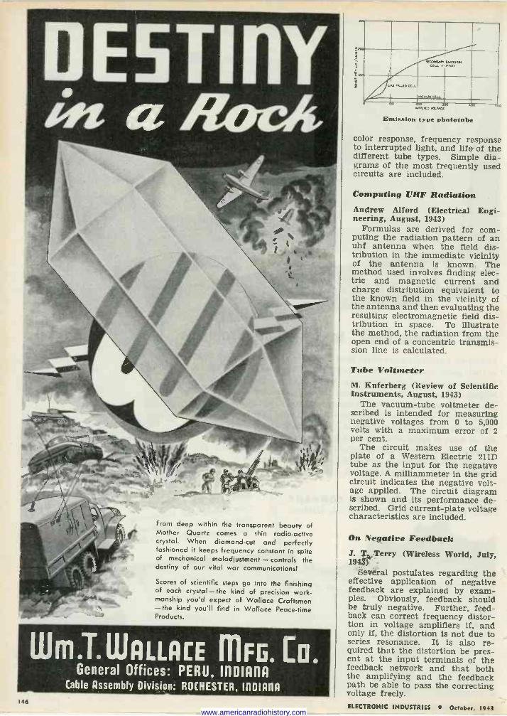
From deep within the transparent beauty of Mother Quartz comes a thin radio -active crystal. When diamond -cut and perfectly fashioned it keeps frequency constant in spite of mechanical maladjustment - controls the destiny of our vital war communications)
Scores of scientific steps go into the finishing of each crystal-the kind of precision work- manship you'd expect of Wallace Craftsmen -the kind you'll find in Wallace Peace -time Products.
Wm.T.WALLA[E mFG. C a General Offices: PERU, IIlDIAl1A
Cable Assembly Division: ROCHESTER, mown 146
'.IRG Kl AF4
Emission type phototube
color response, frequency response to interrupted light, and life of the different tube types. Simple dia- grams of the most frequently used circuits are included.
Computing UHF Radiation Andrew Alford (Electrical Engi- neering, August, 1943)
Formulas are derived for com- puting the radiation pattern of an uhf antenna when the field dis- tribution in the immediate vicinity of the antenna is known. The method used involves finding elec- tric and magnetic current and charge distribution equivalent to the known field in the vicinity of the antenna and then evaluating the resulting electromagnetic field dis- tribution in space. To illustrate the method, the radiation from the open end of a concentric transmis- sion line is calculated.
Tube Voltmeter M. Kuferberg (Review of Scientific Instruments, August, 1943)
The vacuum -tube voltmeter de- scribed is intended for measuring negative voltages from 0 to 5,000 volts with a maximum error of 2 per cent.
The circuit makes use of the plate of a Western Electric 211D tube as the input for the negative voltage. A milliammeter in the grid circuit indicates the negative volt- age applied. The circuit diagram is shown and its performance de- scribed. Grid current -plate voltage characteristics are included.
On Negative Feedback J. T. Terry (Wireless World, July, 194$)'
Several postulates regarding the effective application of negative feedback are explained by exam- ples. Obviously, feedback should be truly negative. Further, feed- back can correct frequency distor- tion in voltage amplifiers if, and only if, the distortion is not due to series resonance. It is also re- quired that the distortion be pres- ent at the input terminals of the feedback network and that both the amplifying and the feedback path be able to pass the correcting voltage freely. ELECTRONIC INDUSTRIES October, 1943 www.americanradiohistory.com
A very large proportion of all the equipment ased today in America's approximately 930 broadcast stations was supplied by FCA.
RCA is the only broadcast equipment supplier oanufaz turing aocomplete line of measuring and test equipment.
ECA' s line of .apparatus includes more of the equipment necessary for the efficient operation of modern broadcasting stations than that of any other manufacturer.
RCA BROADCAST EQUIPMENT RCA jitter Pithier RADIO OPP IleRlITICI A OF AMER1CP - Camden, N. I.
ELECTRONIC INDUSTRIIES October, 1943 147 www.americanradiohistory.com
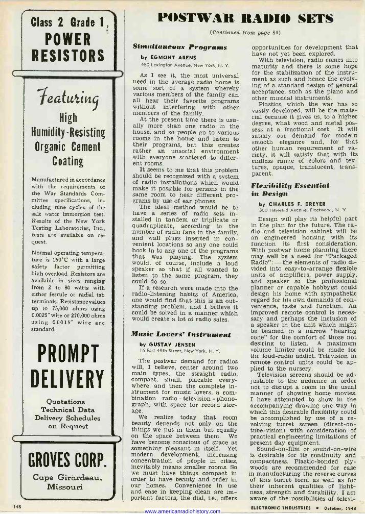
148
Class 2 Grade 1,
POWER RESISTORS
le atut i t'i9
High
Humidity -Resisting
Organic Cement
Coating
Manufactured in accordance with the requirements of the War Standards Com- mittee specifications, in- cluding nine cycles of the salt water immersion test. Results of the New York Testing Laboratories, Inc., tests are available on re- quest.
Normal operating tempera- ture is 160°C with a large safety factor permitting high overload. Resistors are available in sizes ranging from 2 to 80 watts with either ferrule or radial tab terminals. Resistance values up to 75,000 ohms using 0.0025" wire or 270,000 ohms using 0.0015" wire are standard.
PROMPT
DELIVERY Quotations
Technical Data Delivery Schedules
on Request
GROVES CORP. Cape Girardeau,
Missouri
POSTWAR RADIO SETS (Continued from page 84)
Simultaneous Programs by EGMONT ARENS 480 Lexington Avenue, New York, N. Y.
As I see it, the most universal need in the average radio home is some sort of a system whereby various members of the family can all hear their favorite programs without interfering with other members of the family.
At the present time there is usu- ally more than one radio in the house, and so people go to various rooms in the house and listen to their programs, but this creates rather an unsocial environment with everyone scattered to differ- ent rooms.
It seems to me that this problem should be recognized with a system of radio installations which would make it possible for persons in the same room to hear different pro- grams by use of ear phones.
The ideal method would be to have a series of radio sets in- stalled in tandem or triplicate or quadruplicate, according to the number of radio fans in the family, and wall plugs inserted in con- venient locations so any one could hook in to any one of the programs that was playing. The system would, of course, include a loud speaker so that if all wanted to listen to the same program, they could do so.
If a research were made into the radio -listening habits of America, one would find that this is an out- standing problem, and I believe it could be solved in a manner which would create a lot of radio sales.
Music Lovers' Instrument by GUSTAV JENSEN 16 East 48th Street, New York, N. Y.
The postwar demand for radios will, I believe, center around two main types, the straight radio, compact, small, placable every- where, and then the complete in- strument for music lovers, a com- bination radio - television - phono- graph, with space for record stor- age.
We realize today that room beauty depends not only on the things we put in them but equally on the space between them. We have become conscious of space as something pleasant in itself. Yet modern development, increasing concentration of people in cities, inevitably means smaller rooms. So we must have things compact in order to have beauty and order in our homes. Convenience in use and ease in keeping clean are im- portant factors, the dial, i.e., offers
opportunities for development that have not yet been explored.
With television, radio comes into maturity and there is some hope for the stabilization of the instru- ment as such and hence the evolv- ing of a standard design of general acceptance, such as the piano and other musical instruments.
Plastics, which the war has so vastly developed, will be the mate- rial because it gives us, to a higher degree, what wood and metal pos- sess at a fractional cost. It will satisfy our demand for modern smooth elegance and, for that other human requirement of va- riety, it will satisfy that with its endless range of colors and tex- tures, opaque, translucent, trans- parent.
Flexibility Essential in Design
by CHARLES F. DREYER 300 Hayward Avenue, Fleetwood, N. Y.
Design will play its helpful part in the plan for the future. The ra- dio and television cabinet will be an engineered housing with its function its first consideration. With postwar home planning there may well be a need for "Packaged Radio": - the elements of radio di- vided into easy -to -arrange flexible units of amplifiers, power supply, and speaker so the professional planner or capable hobbyist could design his home with sympathetic regard for his own demands of con- venience, taste and function. An improved remote control is neces- sary and perhaps the inclusion of a speaker in the unit which might be beamed to a narrow "hearing cone" for the comfort of those not desiring to listen. A maximum volume limiter could be made for the loud -radio addict. Television in remote control units could be ap- plied to the nursery.
Television screens should be ad- justable to the audience in order not to disrupt a room in the usual manner of showing home movies. I have attempted to show in the accompanying drawing one way in which this desirable flexibility could be accomplished by use of a re- volving turret screen (direct -on - tube -vision) with consideration of practical engineering limitations of present day equipment.
Sound -on -film or sound -on -wire is desirable for its continuity and compactness. Plastic -bonded ply - woods are recommended for ease in manufacturing the reverse curves of this turret form as well as for their inherent qualities . of light- ness, strength and durability. I am aware of the possibilities of televi- ELECTRONIC INDUSTRIES October, 1943 www.americanradiohistory.com
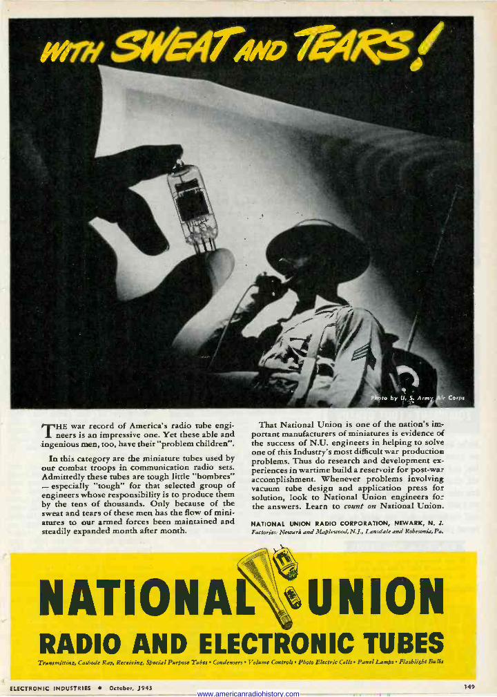
THE war record of America's radio tube engi- neers is an impressive one. Yet these able and
ingenious men, too, have their"problem children".
In this category are the miniature tubes used by our combat troops in communication radio sets. Admittedly these tubes are tough little "hombres" - especially "tough" for that selected group of engineers whose responsibility is to produce them by the tens of thousands. Only because of the sweat and tears of these men has the flow of mini- atures to our armed forces been maintained and steadily expanded month after month.
That National Union is one of the nation's im- portant manufacturers of miniatures is evidence of the success of N.U. engineers in helping to solve one of this Industry's most difficult war production problems. Thus do research and development ex- periences in wartime build a reservoir for post-war accomplishment. Whenever problems involving vacuum tube design and application press for solution, look to National Union engineers for the answers. Learn to count on National Union.
NATIONAL UNION RADIO CORPORATION, NEWARK, N. J.
Factories: Newark and Maplewood, N.J., Lansdale and Robesonia, Pa.
NATIONAL BUNION RADIO AND ELECTRONIC TUBES Transmitting, Caibode Ray, Receiving, Special Purpose Tubes Condensers Volume Controls Photo Electric Cells Panel Lamps Flashlight Bulbs
ELECTRONIC INDUSTRIES October, 1943 149 www.americanradiohistory.com
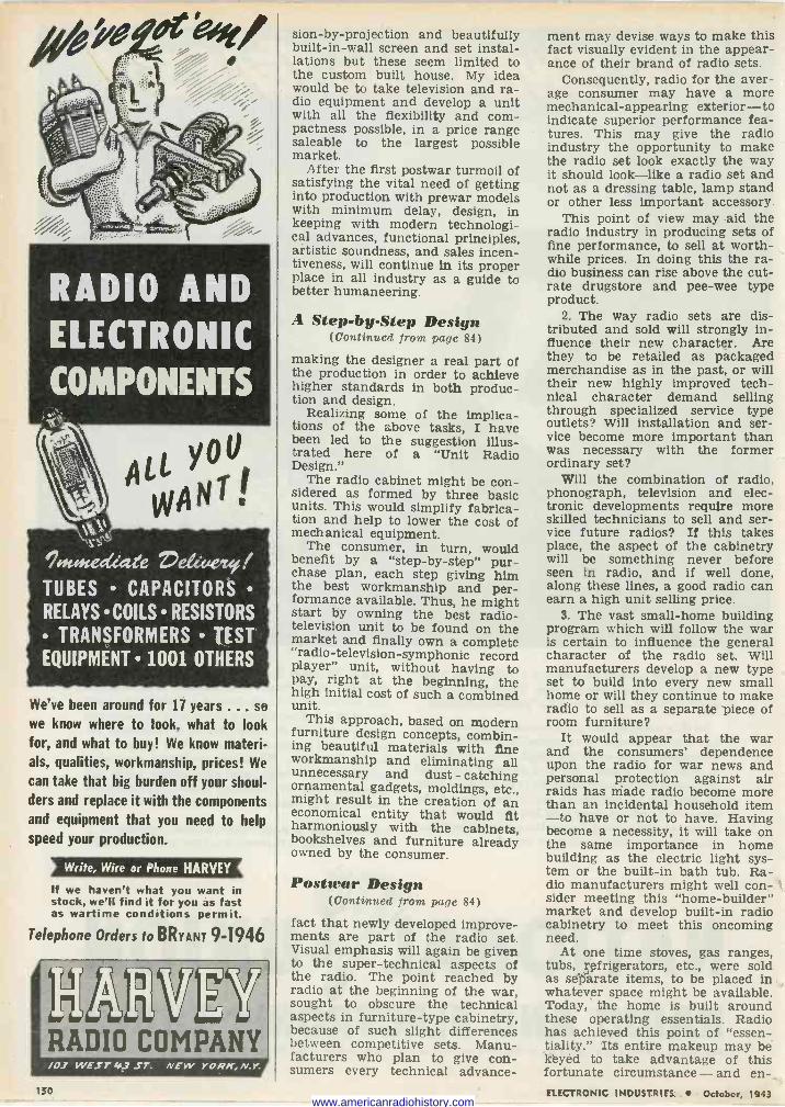
U ALL Y
WANT.
%tedÁate Úeé <eze
TUBES CAPACITORS RELAYS COILS RESISTORS
TRANSFORMERS TEST EQUIPMENT 1001 OTHERS
We've been around for 17 years ... se
we know where to look, what to look for, and what to buy! We know materi- als, qualities, workmanship, prices! We
can take that big burden off your shoul- ders and replace it with the components and equipment that you need to help speed your production.
If we haven't what you want in stock, we'll find it for you as fast as wartime conditions permit.
Telephone Orders to BRYANT 9-1946
Mh1311EY RADIO COMPANY /02 WEST 49 ST. NEW YORK, N.Y.
sion-by-projection and beautifully built -in -wall screen and set instal- lations but these seem limited to the custom built house. My idea would be to take television and ra- dio equipment and develop a unit with all the flexibility and com- pactness possible, in a price range saleable to the largest possible market.
After the first postwar turmoil of satisfying the vital need of getting into production with prewar models with minimum delay, design, in keeping with modern technologi- cal advances, functional principles, artistic soundness, and sales íncen- tiveness, will continue in its proper place in all industry as a guide to better humaneering.
A Step -by -Step Design (Continued from page 84)
making the designer a real part of the production in order to achieve higher standards in both produc- tion and design.
Realizing some of the implica- tions of the above tasks, I have been led to the suggestion illus- trated here of a "Unit Radio Design."
The radio cabinet might be con- sidered as formed by three basic units. This would simplify fabrica- tion and help to lower the cost of mechanical equipment.
The consumer, in turn, would benefit by a "step-by-step" pur- chase plan, each step giving him the best workmanship and per- formance available. Thus, he might start by owning the best radio - television unit to be found on the market and finally own a complete "radio -television -symphonic record player" unit, without having to pay, right at the beginning, the high initial cost of such a combined unit.
This approach, based on modern furniture design concepts, combin- ing beautiful materials with fine workmanship and eliminating all unnecessary and dust - catching ornamental gadgets, moldings, etc., might result in the creation of an economical entity that would fit harmoniously with the cabinets, bookshelves and furniture already owned by the consumer.
Postwar Design (Continued from page 84)
fact that newly developed improve- ments are part of the radio set. Visual emphasis will again be given to the super -technical aspects of the radio. The point reached by radio at the beginning of the war, sought to obscure the technical aspects in furniture -type cabinetry, because of such slight differences between competitive sets. Manu- facturers who plan to give con- sumers every technical advance-
ment may devise ways to make this fact visually evident in the appear- ance of their brand of radio sets.
Consequently, radio for the aver- age consumer may have a more mechanical -appearing exterior - to indicate superior performance fea- tures. This may give the radio industry the opportunity to make the radio set look exactly the way it should look-like a radio set and not as a dressing table, lamp stand or other less important accessory.
This point of view may aid the radio industry in producing sets of fine performance, to sell at worth- while prices. In doing this the ra- dio business can rise above the cut- rate drugstore and pee -wee type product.
2. The way radio sets are dis- tributed and sold will strongly in- fluence their new character. Are they to be retailed as packaged merchandise as in the past, or will their new highly improved tech- nical character demand selling through specialized service type outlets? Will installation and ser- vice become more important than was necessary with the former ordinary set?
Will the combination of radio, phonograph, television and elec- tronic developments require more skilled technicians to sell and ser- vice future radios? If this takes place, the aspect of the cabinetry will be something never before seen in radio, and if well done, along these lines, a good radio can earn a high unit selling price.
3. The vast small -home building program which will follow the war is certain to influence the general character of the radio set. Will manufacturers develop a new type set to build into every new small home or will they continue to make radio to sell as a separate piece of room furniture?
It would appear that the war and the consumers' dependence upon the radio for war news and personal protection against air raids has made radio become more than an incidental household item -to have or not to have. Having become a necessity, it will take on the same importance in home building as the electric light sys- tem or the built-in bath tub. Ra- dio manufacturers might well con- sider meeting this "home -builder" market and develop built-in radio cabinetry to meet this oncoming need.
At one time stoves, gas ranges, tubs, refrigerators, etc., were sold as separate items, to be placed in whatever space might be available. Today, the home is built around these operating essentials. Radio has achieved this point of "essen- tiality." Its entire makeup may be kéyed to take advantage of this fortunate circumstance - and en-
1s0 ELECTRONIC INDUSTRIES . October, 1943 www.americanradiohistory.com
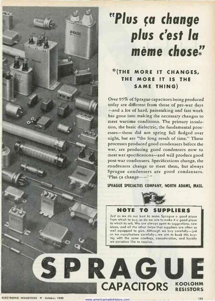
«Plus ça change plus c'est la même chose*'
*(THE MORE IT CHANGES, THE MORE IT IS THE
SAME THING)
Over 95% of Sprague capacitors being produced today are different from those of pre-war days -and a lot of hard, painstaking and fast work has gone into making the necessary changes to meet wartime conditions. The primary insula- tion, the basic dielectric, the fundamental proc- esses-these did not spring full fledged over night, but are "the long result of time." These processes produced good condensers before the war, are producing good condensers now to meet war specifications-and will produce good post-war condensers. Specifications change, the condensers change to meet them, but always Sprague condensers are good condensers. 'Plus ca change--' "
SPRAGUE SPECIALTIES COMPANY, NORTH ADAMS, MASS.
get et-
NAV't/
NOTE TO SUPPLIERS Just as we do our best to make Sprague a good place from which to buy, so do we aim to make it a good place to which to sell. We are always open to suggestions, new ideas, and all the other helps that suppliers are often so well equipped to give. Although we buy carefully-just as we manufacture carefully-we aim to back this buy- ing with the same courtesy, consideration, and loyalty we ourselves like to receive.
SPRAGUE CAPACITORS KOOLOHM
RESISTORS
ELECTRONIC INDUSTRIES October, 1943 151 www.americanradiohistory.com
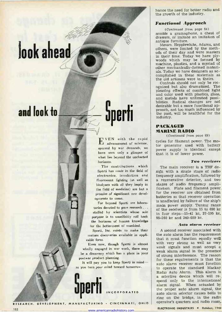
Sporti
EVEN with the rapid advancement of science,
spurred by war demands, we
have seen only a glimpse of what lies beyond the uncharted horizons.
The contributions which Sperti has made in the field of electronics, irradiation and fluorescent lighting (as well as
hiodynes with all they imply in the field of medicine) are but a
promise of significant new devel-
opments to come. For beyond Sperti are labora-
tories devoted to pure research ... staffed by scientists whose sole
purpose is to unselfishly roll hack the horizons of human knowledge
for the betterment of mankind. Sperti, Inc. exists to make their
mature discoveries available in appli- cable form.
Even now, though Sperti is almost wholly engaged in war work, there may
be a discovery which has a place in your postwar product planning.
It will pay you to keep Sperti in mind- as you turn your mind toward tomorrow.
Sporti INCORPORATED
RESEARCH, DEVELOPMENT, MANUFACTURING CINCINNATI, OHIO
hance the need for better radio and the growth of the industry.
Functional Approach (Continued from page 84)
semble a gramaphone, a chest of drawers, or imitate an imitation of antique furniture.
Messrs. Hepplewhite, Adams, and others, were limited by the meth- ods of their day and were masters in their time. Today we have ply - woods which may be formed by machine, plastics, and a myriad of other mechanically -formed materi- als. Today we have designers as ac- complished in these materials as the old artisans were in theirs.
Controls should not only be rec- ognized but also dramatized. The pleasing effects of combined light and color used with plastics, glass, and metals have unlimited possi- bilities. Radical changes are not desirable but a more functional ap- proach, not too much influenced by the past, will be healthful for the industry.
PACKAGED MARINE RADIO
(Continued from page 89)
cycles for filament power. The mo- tor generator used with battery power supply is identical except that it is of lower power.
Two receivers The main receiver is a TRF de-
sign with a single stage of radio frequency amplification, followed by a regenerative detector, and two stages of audio frequency ampli- fication. Plate and filament power for the receiver are obtained from batteries so that receiver operation is unaffected by failure of the ship's main power supply. Tuning range of the receiver is from 15 to 650 kc in four steps -15-41 kc, 37-105 kc, 95-260 kc and 240-650 kc.
Auto alarm receiver A second receiver associated with
the auto alarm has the requirement that it must function equally well with very strong as well as very weak signals and must accept a weak alarm signal in the presence of strong interference. The reason for these requirements is that the auto alarm receiver must function to operate the standard Mackay Radio Auto Alarm. This alarm is a selective device which will re- spond only to the international alarm signal. When actuated by the proper auto alarm signal, the auto alarm selector causes bells to ring on the bridge, in the radio operator's quarters and radio room,
1S2 ELECTRONIC INDUSTRIES October, 1943 www.americanradiohistory.com
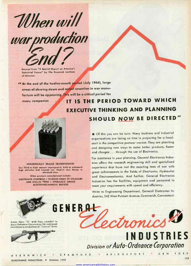
'When iwill «ìiproduc/i'n
SW? 47 Excerpt from "A Special Report on America's
Industrial Future" by The Research Institute
of America.
" At the end of the twelve-month period (July 1944), large
areas of slowing down and actual cessation in war manu-
facture will be appearing. This will be a critical period for
many companies IT IS THE PERIOD TOWARD WHICH
EXECUTIVE THINKING AND PLANNING
SHOULD NOW BE DIRECTED
HERMETICALLY SEALED TRANSFORMERS
Gas filled or high vacuum impregnated. Built to withstand high altitudes and tropical use. Modern case design in
standard sizes.
Other products manufactured include:
ELECTRONIC CONTROLS VACUUM TUBES OF STANDARD AND SPECIAL TYPES HYDRAULIC SERVOS
ELECTROMECHANICAL DEVICES
GENE Army -Navy "E" with Star, awarded to Auto -Ordnance Corporation for continued excellence in production of "Tommy" Guns
Of this you can be sure: Many business and industrial
organizations are losing no time in preparing for a head -
start in the competitive postwar market. They are planning
and designing new ways to make better products, faster
and cheaper ... through the use of Electronics.
For assistance in your planning, General Electronics Indus-
tries offers the research engineering skill and specialized
experience that have met the exacting tests of war with
great achievements in the fields of Electronics, Hydraulics
and Electromechanics. And further, General Electronics
Industries has the facilities, equipment and personnel to
meet your requirements with speed and efficiency.
Write to Engineering Department, General Electronics In-
dustries, 342 West Putnam Avenue, Greenwich, Connecticut.
I/
INDUSTRIES Division of Auk -Ordnance Corporation
t3 R E E N W I C H STAMFORD ELECTRONIC INDUSTRIES October, 1943
BRIDGEPOR T NEW YORK 153
www.americanradiohistory.com
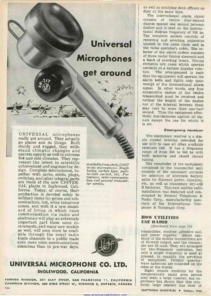
Universal
Microphones
get around
'-=-
- - _
rn .00,,r,.
UNIVERSAL microphones really get around. They actually go places and do things. Built sturdy and rugged, they with- stand climatic changes and operate equally as well in extreme hot and cold climates. They rep- resent the latest in scientific achievement and engineering de- sign. Complete microphones, to- gether with jacks, cords, plugs, switches, and other integral parts are made at the new UNIVER- SAL plants in Inglewood, Cali- fornia. Today, of course, their production is devoted solely to military items for prime and sub- contractors, but, when tomorrow comes, and with it a new stand- ard of living in which voice communication via radio and electronics will play an extremely important part these same in- struments, and many new models as well, will once more be avail- able through the usual radio trade channels to a public made even more voice communications conscious than in pre-war days.
Available f rom stock,1700U series microphone. Single button carbon type, push - to -talk switch, etc. For trainers, inter -communica- tion and general transmit- ter service.
UNIVERSAL MICROPHONE CO. LTD. INGLEWOOD, CALIFORNIA
M
FOREIGN DIVISION, 301 CLAY STREET, SAN FRANCISCO 11, CALIFORNIA CANADIAN DIVISION, 560 KING STREET W., TORONTO 2, ONTARIO, CANADA 154
as well as notifying deck officers on duty at the same time.
The international alarm signal consists of twelve four -second dashes spaced one second between dashes and is sent on the interna- tional distress frequency of 500 kc. The complete system consists of receiving and selecting apparatus located in the radio room and in the radio operator's cabin. The se- lector of the alarm system consists of three motor timing elements and a bank of counting relays. Timing elements are cams which operate contacts at a certain angular rota- tion. The arrangement is such that the equipment will operate the alarm bells and lights only upon receipt of the international alarm signal. In other words, any four consecutive dashes of the twelve transmitted must be received and neither the length of the dashes nor of the interval between them may vary by more than one-half second. Thus the equipment effec- tively discriminates against all sig- nals except the one for which it is set.
Emergency receiver The emergency receiver is a sim-
ple crystal detector intended for use only in case all other available receivers fail. It has a frequency range of from 350 to 550 kc with both antenna and closed circuit tuning.
The remainder of the equipment contained in the transmitter unit consists of the necessary controls for selection of alternate battery units for filament power, charging, etc., as well as emergency dry -cell B batteries. This new marine radio installation was designed and con- structed by Federal Telephone & Radio Corp., manufacturing asso- ciate of the International Tele- phone & Telegraph Corp.
HOW UTILITIES USE RADIO
(Continued from page 81)
transmitter, receiver, selective call, and power supplies. About one- third of the mobile transmitters are of 35 -watt output, and the remain- der are 25 -watt. They are arranged for two -frequency operation, but only a single frequency is used at present, to simplify the servicing of equipment. Vertical quarter - wave antennas are mounted on the sides of the trucks.
Eight remote receivers for the comparatively small area served may seem a large number, but ex- perience has shown that this rela- tively large number has been of ELECTRONIC INDUSTRIES October, 1943
www.americanradiohistory.com
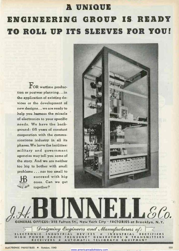
A UNIQUE ENGINEERING GROUP IS READY TO ROLL UP ITS SLEEVES FOR YOU!
FOR wartime produc- tion or postwar planning ...in the application of existing de-
vices or the development of
new designs... we are ready to
help you harness the miracle of electronics to your specific needs. We have the back- ground: 65 years of constant cooperation with the commu- nications industry in all its phases. We have the facilities: military and government agencies may tell you some of
the story. And we are neither too big to bother with small problems ... nor too small to
113 succeed with big ones. Can we get
SINCE 1818 together?
GENERAL OFFICES: 215 Fulton St., New York City FACTORIES at Brooklyn, N. Y.
=;!'I'.Sf jll- lll j lll(1tP71 4l?< ̀ '<l1ltCFII/_?l4 <1' r i ELECTRONIC INDUSTRIAL DEV'C f S * IN )USTRIAL RECTIFIERS HIGH POWER RADIO FREQUENCY GENERATORS * TRANSMITTERS
RECEIVERS * AUTOMATIC TELEGRAPH EQUIPMENT
ELECTRONIC INDUSTRIES October, 1543 155 www.americanradiohistory.com
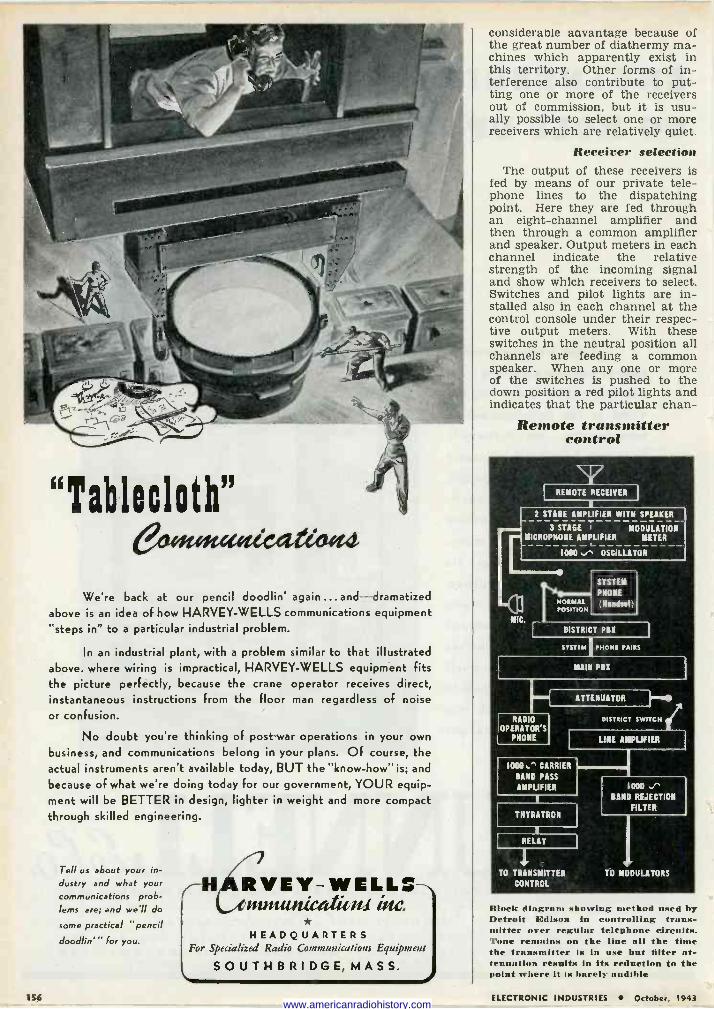
"Tablecloth" emtotagied.eioet4
We're back at our pencil doodlin' again ...and dramatized above is an idea of how HARVEY -WELLS communications equipment "steps in" to a particular industrial problem.
In an industrial plant, with a problem similar to that illustrated above. where wiring is impractical, HARVEY -WELLS equipment fits the picture perfectly, because the crane operator receives direct, instantaneous instructions from the floor man regardless of noise or confusion.
No doubt you're thinking of post-war operations in your own
business, and communications belong in your plans. Of course, the actual instruments aren't available today, BUT the "know-how" is; and
because of what we're doing today For our government, YOUR equip- ment will be BETTER in design, lighter in weight and more compact through skilled engineering.
Tell us about your in- dustry and what your
communications prob- lems are; and we'll do
some practical "pencil
doodlin''' for you.
H,ARYEY-WELLS iftIwuuucalu Nat
HEADQUARTERS For Specialized Radio Communications Equipment
SOUTHBRIDGE,MASS.
considerable aavantage because of the great number of diathermy ma- chines which apparently exist in this territory. Other forms of in- terference also contribute to put- ting one or more of the receivers out of commission, but it is usu- ally possible to select one or more receivers which are relatively quiet.
Receiver selection The output of these receivers is
fed by means of our private tele- phone lines to the dispatching point. Here they are fed through an eight -channel amplifier and then through a common amplifier and speaker. Output meters in each channel indicate the relative strength of the incoming signal and show which receivers to select. Switches and pilot lights are in- stalled also in each channel at the control console under their respec- tive output meters. With these switches in the neutral position all channels are feeding a common speaker. When any one or more of the switches is pushed to the down position a red pilot lights and indicates that the particular chan -
Remote transmitter control
REMOTE RECEIVER
K
2 STAGE AMPLIFIER WITH SPEAKER
3 STAGE T MODULATION MICROPHONE AMPLIFIER METER
1000.." OSCILLATOR
MIC.
NORMAL POSITION
SYSTEM
PHONE
(Handtat)
DISTRICT PBX
SYSTEM
RADIO OPERATOR'S
PHONE
1000.^ CARRIER
BAND PASS
AMPLIFIER
THYRATRON
RELAY
1 -
TO TRANSMITTER CONTROL
PHONE PAIRS
MAIN PBX
ATTENUATOR
DISTRICT SWITCH
LINE AMPLIFIER
1000 ./` BAND REJECTION
FILTER
TO MODULATORS
Block diagram showing method used by Detroit Edison in controlling trans- mitter over regular telephone circuits. Tone remains on the line all the time the transmitter is in use but filter at- tenuation results in its reduction to the point where it is barely audible
156 ELECTRONIC INDUSTRIES October, 1943 www.americanradiohistory.com
Laboratory Standards ... Precision DC and
AC Portables ... Instrument Transformers
... Sensitive Relays ... DC, AC, and
Thermo Switchboard and Panel Instruments.
Photronic Cells now being made for war purposes only, hold many new possibilities for design engineers searching for better methods or new products for post-war markets.
The improved Type 3 photo -cell has a marked increase in sensitivity and can be produced in various outputs and various linearity factors, to meet specific circuit requirements. They can be matched in spectral sensitivity, too; to give practically the same spectral response curve throughout the color spectrum. And since the fatigue factor has been materially reduced, their response is more uniform, and far more rapid.
The development of the Type 3 is the result of continued research and experience in the processing of photo -cells dating back to 1930.. .
the year in which WESTON introduced the first American -made com- mercial cell of the barrier -layer type.
Type 3 Photronic Cells can be supplied in various styles and cases, as well as unmounted in a variety of shapes and sizes. Complete technical data, in booklet form, available to design engineers on request. Weston Electrical Instrument Corporation, 666 Frelinghuysen Avenue,
Newark, New Jersey. *PHOTRONIC-A registered trademark designating the photoelectric cells and photo- electric devices manufactured exclusively by the Weston Electrical Instrument Corp.
WESTON Specialized Test Equipment ... Light Measurement and Control Devices .. .
Exposure Meters...Aircraft Instruments...
Electric Tachometers...Dial Thermometers.
FOR OVER JI YEARS LENDERS lV- ELECTRICAL MEASURING INSTRUMENTA;
ELECTRONIC INDUSTRIES October, 1943 157
www.americanradiohistory.com
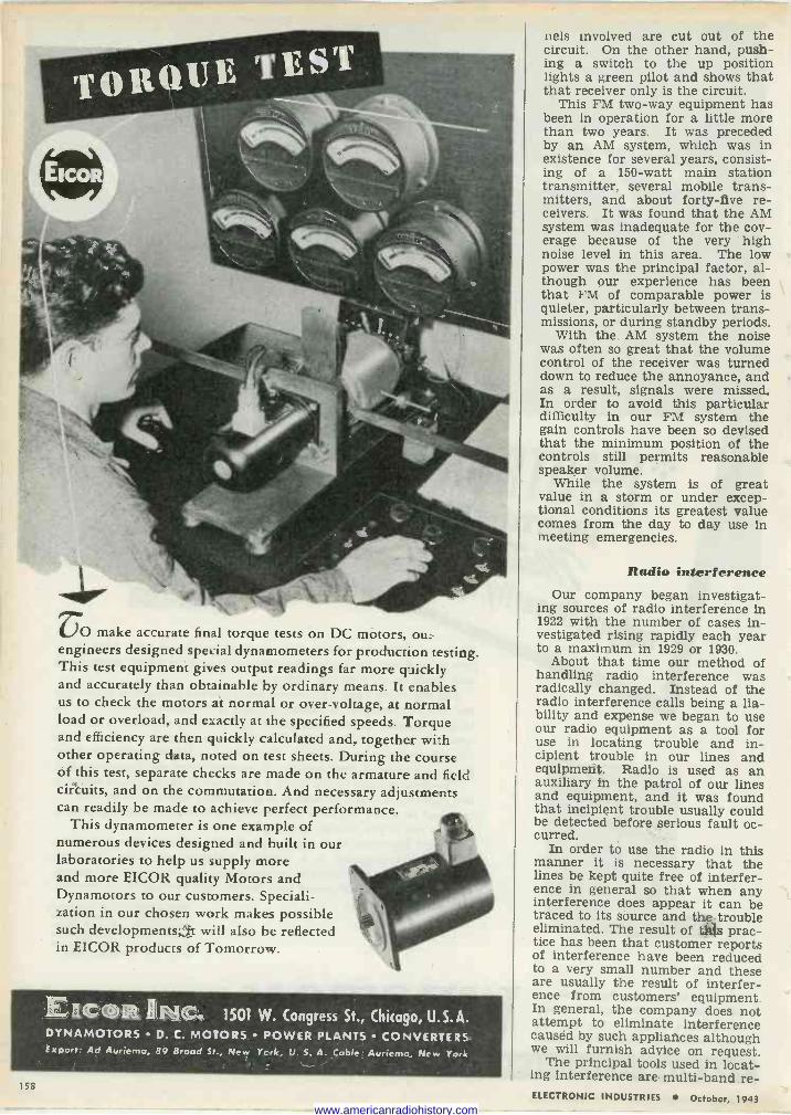
VO make accurate final torque tests on DC motors, ou_ engineers designed special dynamometers for production testing. This test equipment gi%es output readings far more quickly and accurately than obtainable by ordinary means. It enables us to check the motors at normal or over -voltage, at normal load or overload, and exactly at the specified speeds. Torque and efficiency are then quickly calculated and, together with other operating data, noted on test sheets. During the course of this test, separate checks are made on the armature and field circuits, and on the commutation. And necessary adjustments can readily be made to achieve perfect performance.
This dynamometer is one example of numerous devices designed and built in our laboratories to help us supply more and more EICOR quality Motors and Dynamotors to our customers. Speciali- zation in our chosen work makes possible such developments;;fit will also be reflected in EICOR products of Tomorrow.
_,I cent n Rime 1501 W. Congress St., Chicago, U.S.A. DYNAMOTORS D. C. MOTORS POWER PLANTS CONVERTERS. Export: Ad Auriema, 89 Broad St., New York, U. S. A. Coble: Auriemo,, New York
158
nets involved are cut out of the circuit. On the other hand, push- ing a switch to the up position lights a green pilot and shows that that receiver only is the circuit.
This FM two-way equipment has been in operation for a little more than two years. It was preceded by an AM system, which was in existence for several years, consist- ing of a 150 -watt main station transmitter, several mobile trans- mitters, and about forty-five re- ceivers. It was found that the AM system was inadequate for the cov- erage because of the very high noise level in this area. The low power was the principal factor, al- though our experience has been that FM of comparable power is quieter, particularly between trans- missions, or during standby periods.
With the AM system the noise was often so great that the volume control of the receiver was turned down to reduce the annoyance, and as a result, signals were missed. In order to avoid this particular difficulty in our FM system the gain controls have been so devised that the minimum position of the controls still permits reasonable speaker volume.
While the system is of great value in a storm or under excep- tional conditions its greatest value comes from the day to day use in meeting emergencies.
Radio interference Our company began investigat-
ing sources of radio interference in 1922 with the number of cases in- vestigated rising rapidly each year to a maximum in 1929 or 1930.
About that time our method of handling radio interference was radically changed. Instead of the radio interference calls being a lia- bility and expense we began to use our radio equipment as a tool for use in locating trouble and in- cipient trouble in our lines and equipment. Radio is used as an auxiliary in the patrol of our lines and equipment, and it was found that incipient trouble usually could be detected before serious fault oc- curred.
In order to use the radio In this manner it is necessary that the lines be kept quite free of interfer- ence in general so that when any interference does appear it can be traced to its source and the,trouble eliminated. The result of tes prac- tice has been that customer reports of interference have been reduced to a very small number and these are usually the result of interfer- ence from customers' equipment. In general, the company does not attempt to eliminate interference caused by such appliances although we will furnish advice on request.
The principal tools used in locat- ing interference are multi -band re - ELECTRONIC INDUSTRIES October, 1943
www.americanradiohistory.com
...BY EAR A fighting man must fly blind sometimes, bur deaf never. In loig range bombers ... in scrappy pursuit planes . . whomever the visibility, vital communication channels must be kept clear. Unless the proper suppression fil :er system is installed, noisy radio interference acts like a pack of demons ... sabotages communications upon which the safety of men and their military missions Cep and.
Solar Elim-O-Stats are Communcati.rs' Life-savers. They are compact filters which protect against local static, s.bso i ing it right where it starts-at generators, motors, contacts, and other sources. Sala- Capacitors are reliable components used by practically all leading manufacturers of mi.itary radio epuipment. From com- mand car to jeep or tank ... frown ship to ship or plane ... between planes- wherever radio is vital-Solar Capacitors and Elim-O-Brats help keep channels clear, so fighting men can hear.
If you have a problem concerning capacitors or radio noise suppression, call on Solar Manufacturing Corporation, 285 Madison Atie., New York 17, N. Y.
ELI Al O--STATS - FILTER S CAPACITORS AND RADIO NOISE -SUPPRESSION
www.americanradiohistory.com
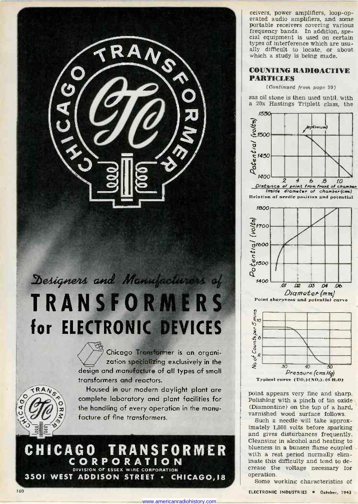
Chicago Transfòrnler is an organi- zation specializing exclusively in the
design and manufacture of all types of small transformers and reactors.
Housed in our modern daylight plant are complete laboratory and plant facilities for the handling of every operation in the manu- facture of fine transformers.
CHICAGO TRANSFORMER CORPORATION
DIVISION OF ESSEX WIRE CORPORATION
3501 WEST ADDISON STREET CHICAG0,18
ceivers, power amplifiers, loop -op- erated audio amplifiers, and some portable receivers covering various frequency bands. In addition, spe- cial equipment is used on certain types of interference which are usu- ally difficult to locate, or about which a study is being made.
COUNTING RADIOACTIVE PARTICLES
(Continued from page 99)
sas oil stone is then used until, with a 20x Hastings Triplett glass, the
1550
o 1N
-44 1450
+o
Q 1400
,(optimums)
.2 4 .6 .8 10 Distance of point from front of chamber
Inside diameter of chambcr(cwa) Relation of needle position and potential
1800
ñ -44 f700 o
21600
C
1500
1400
(vz .01 lag .03 .Ot .06
Diameter` (mm) Point sharpness and potential carve
c
10
.4 6 C
O U2
.30 40 50 Preaaure (cmo Hy)
Typical curve (UO2) (r0a)2 (ß 1120)
point appears very fine and sharp. Polishing with a pinch of tin oxide (Diamontine) on the top of a hard, varnished wood surface follows.
Such a needle will take approx- imately 1,800 volts before sparking and gives disturbances frequently. Cleansing in alcohol and heating to blueness in a bunsen flame coupled with a rest period normally elim- inate this difficulty and tend to de- crease the voltage necessary for operation.
Some working characteristics of 160 ELECTRONIC INDUSTRIES October, 1943
www.americanradiohistory.com
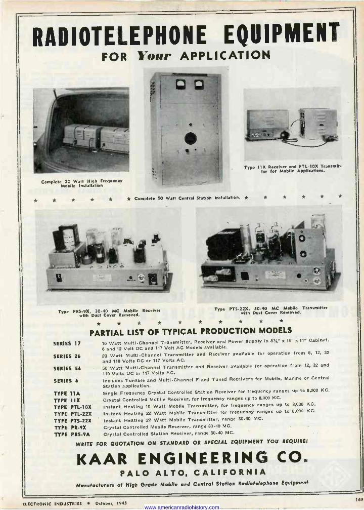
RADIOTELEPHONE EQUIPMENT FOR Your APPLICATION
Type 11X Receiver and PTL-10X Transmit- ter for Mobile Applications.
Complete 22 Watt High Frequency Mobile Installation
* * * * * * Complete 50 Watt Central Station Installation. * * * * * *
Type PRS -9X, 30-40 MC Mobile Receiver Type PTS-22X, 30-40 MC Mobile Transmitter
with Dust Cover Removed. with Dust Cover Removed.
* * * * * * * * * *
PARTIAL LIST OF TYPICAL PRODUCTION MODELS
SERIES 17 10 Watt Multi -Channel Transmitter, Receiver and Power Supply in 83/4" x 15" x 11" Cabinet.
6 and 12 Volt DC and 117 Volt AC Models available.
SERIES 26 20 Watt Multi -Channel Transmitter and Receiver available for operation from 6, 12, 32
and 110 Volts DC or 117 Volts AC.
SERIES 56 50 Watt Multi -Channel Transmitter and Receiver available for operation from 12, 32 and
110 Volts DC or 117 Volts AC.
SERIES 6 Includes Tunable and Multi -Channel Fixed Tuned Receivers for Mobile, Marine or Central
Station application.
TYPE 11A Single Frequency Crystal Controlled Station Receiver for frequency ranges up to 8,000 KC.
TYPE 11X Crystal Controlled Mobile Receiver, for frequency ranges up to 8,000 KC.
TYPE PTL-10X Instant Heating 10 Watt Mobile Transmitter, for frequency ranges up to 8,000 KC.
TYPE PTL-22X Instant Heating 22 Watt Mobile Transmitter for frequency ranges up to 8,000 KC.
TYPE PTS-22X Instant Heating 22 Watt Mobile Transmitter, range 30-40 MC.
TYPE PR -9X Crystal Controlled Mobile Receiver, range 30-40 MC.
TYPE PRS -9A Crystal Controlled Station Receiver, range 30-40 MC.
WRITE FOR QUOTATION ON STANDARD OR SPECIAL EQUIPMENT YOU REQUIRE!
KAAR ENGINEERING CO. PALO ALTO, CALIFORNIA
Manufacturers of High Grade Mobile and Central Station Radiotelephone Equipment
161 ELECTRONIC INDUSTRIES October, 1943
www.americanradiohistory.com
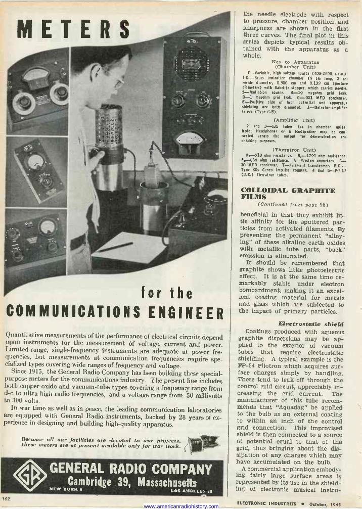
COMMUNICATIONS ENGINEER Quantitative measurements of the performance of electrical circuits depend upon instruments for the measurement Of voltage, current, and power. Limited -range, single -frequency instruments, are adequate at power fre- quencies, but measurements at communication frequencies require spe- cialized types covering wide ranges of frequency and voltage.
Since 1915, the General Radio Company has been building these special- purpose meters for the communications industry. Thé present line includes both copper -oxide and vacuum -tube types covering a frequency range from d -c to ultra -high radio frequencies, and a voltage range from 50 millivolts to 300 volts.
In war time as well as in peace, the leading communication laboratories are equipped with General Radio instruments, backed by 28 years of ex- perience in designing and building high -quality apparatus.
Because all our facilities are devoted to war projects, these meters are at present available only for war work.
GENERAL RADIO COMPANY Cambridge 39, Massachusetts
NEW YORK 6 LOS ANGELES 38
the needle electrode with respect to pressure, chamber position and sharpness are shown in the first three curves. The final plot in this series depicts typical results ob- tained with the apparatus as a whole.
Key to Apparatus (Chamber Unit)
T-Variable, high voltage source (400-2500 v.d.c.). I.C.-Brass ionization chamber (4 cm long, 2 cm inside diameter, 0.300 cm and 0.139 cm aperture diameters) with Bakelite stopper, which carries needle. S-Radiation source. A-10 megohm grid leak. B-1 megohm grid leak. C-.001 MFD condenser. E-Positive side of high potential and apparatus shielding are both grounded. 1-Detector-amplifier triode (Type 6J5).
(Amplifier Unit) 2 and 3-6J5 tubes (as in chamber unit).
Note: Headphones or a loudspeaker may be con- nected across the output for demonstration and checking purposes.
(Thyratron Unit) R,-910 ohm resistance. R5-1790 ohm resistance.
R8--630 ohm resistance. A-Weston ammeters. C- 20 MFD condenser. T-Filament transformer. E.C.- Type 60s Cenco impulse counter. 4 and 5-FG-17 (G.E.) Thyratron tubes.
COLLOIDAL GRAPHITE FILMS
(Continued from page 98)
beneficial in that they exhibit lit- tle affinity for the sputtered par- ticles from activated filaments. By preventing the permanent "alloy- ing" of these alkaline earth oxides with metallic tube parts, "back" emission is eliminated.
It should be remembered that graphite shows little photoelectric effect. It is at the same time re- markably stable under electron bombardment, making It an excel- lent coating material for metals and glass which are subjected to the impact of primary particles.
Electrostatic shield Coatings produced with aqueous
graphite dispersions may be ap- plied to the exterior of vacuum tubes that require electrostatic shielding. A typical example is the FP -54 Pliotron which acquires sur- face charges simply by handling. These tend to leak off through the control grid circuit, appreciably in- creasing the grid current. The manufacturer of this tube recom- mends that "Aquadag" be applied to the bulb as an external coating to within an inch of the control grid connection. This improvised shield is then connected to a source of potential equal to that of the grid, thus bringing about the dis- sipation of any charges which may have accumulated on the bulb.
A commercial application embody- ing fairly large surface areas is represented by its use In the shield- ing of electronic musical instru-
162 ELECTRONIC INDUSTRIES October, 1943 www.americanradiohistory.com
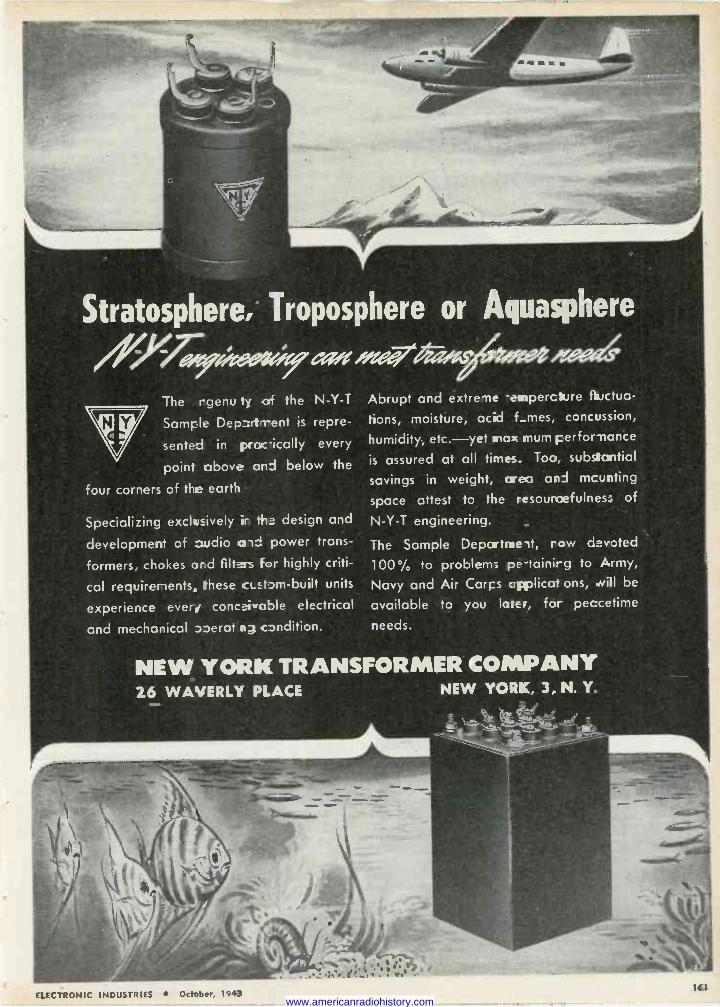
Stratosphere, Troposphere or Aquasphere
//e7».7bAezejycges Area4
The rgenu ty of the N -Y -T
Sample Depzrt-rent is repre-
sented in pracically every
point above and below the
four corners of the earth
Specializing exclusively it the design and
development of audio a is power trans-
formers, chokes and filters For highly criti-
cal requirements, these cLEtpm-built units
experience every conc+iwajle electrical
and mechanical »erat condition.
Abrupt and extreme -enperciure fluctua-
tions, moisture, acid f_mes, concussion,
humidity, etc.-yet wax mum performance
is assured at all times. Too, substantial
savings in weight, area and mcunting
space attest to the
N -Y -T engineering.
The Sample Departroeit,
resourcefulness; of
row devoted
100%, to problem; pe-tainirg to Army,
Navy and Air Corp applicat ons, .will be
available to you la -e-, for peccetime
needs.
NEW YORK TRANSFORMER COMPANY 26 WAVERLY PLACE NEW YORK, 3, N. Y.
: s,.. r . . . ..
ELECTRONIC INDUSTRIES Oc FI er, 1943 16'$
www.americanradiohistory.com
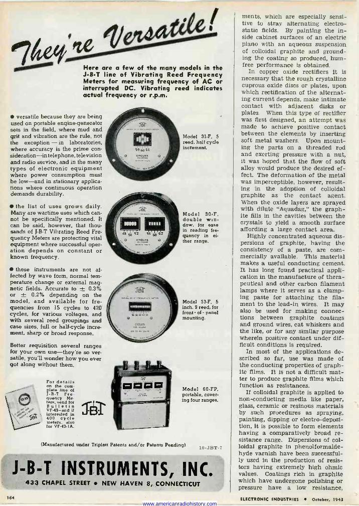
Here are a few of the many models in the J -B -T line of Vibrating Reed Frequency Meters for measuring frequency of AC or interrupted DC. Vibrating reed indicates actual frequency or r.p.m.
versatile because they are being used on portable engine -generator sets in the field, where mud and grit and vibration are the rule, not the exception - in laboratories, where accuracy is the prime con- sideration-in telephone, television and radio service, and in the many types of electronic equipment where power consumption must be low-and in stationary applica- tions where continuous operation demands durability.
the list of uses grows daily. Many are wartime uses which can- not be specifically mentioned. It can be said, however, that thou- sands of J -B -T Vibrating Reed Fre- quency Meters are protecting vital equipment where successful oper- ation depends on constant or known frequency.
these instruments are not af- fected by wave form, normal tem- perature change or external mag- netic fields. Accurate to ± 0.3% or ± 0.2% depending on the model, and available for fre- quencies from 15 cycles to 420 cycles, for various voltages, and with several reed groupings and case sizes, full or half -cycle incre- ment, sharp or broad response.
Better requisition several ranges for your own use-they're so ver- satile, you'll wonder how you ever got along without them.
For details on the com- plete line of JB -T Fre- quency Me- ters. send for Bulletin VF-43-and if interested in 400 cycle meters, also for VF -43.1A.
Model 31-F, 5
reed. half cycle increment.
Model 30-F, double win- dow, for ease in reading fre- quency in ei- ther range.
Model 53-F, 5 inch. 9 reed, for front - of - panel mounting.
Model 60 -FP, portable, cover- ing four ranges.
(Manufactured under Triplett Patents and/or Patents Pending) 10-JHT-7
LB -T INSTRUMENTS, INC. 433 CHAPEL STREET NEW HAVEN 8, CONNECTICUT
ments, which are especially sensi- tive to stray alternating electro- static fields. By painting the in- side cabinet surfaces of an electric piano with an aqueous suspension of colloidal graphite and ground- ing the coating so produced, hum - free performance is obtained.
In copper oxide rectifiers it is necessary that the rough crystalline cuprous oxide discs or plates, upon which rectification of the alternat- ing current depends, make intimate contact with adjacent disks or plates. When this type of rectifier was first designed, an attempt was made to achieve positive contact between the elements by inserting soft metal washers. Upon mount- ing the parts on a threaded rod and exerting pressure with a nut, it was hoped that the flow of soft alloy would produce the desired ef- fect. The deformation of the metal was imperceptible, however, result- ing in the adoption of colloidal graphite as the contact agent. When the oxide layers are sprayed with dilute "Aquadag," the graph- ite fills in the cavities between the crystals to yield a smooth surface affording a large contact area.
Highly concentrated aqueous dis- persions of graphite, having the consistency of a paste, are com- mercially available. This material makes a useful conducting cement. It has long found practical appli- cation in the manufacture of thera- peutical and other carbon filament lamps where it serves as a clamp- ing paste for attaching the fila- ment to the lead-in wires. It may also be used for making connec- tions between graphite coatings and ground wires, cat whiskers and the like, or for any similar purpose wherein positive contact under dif- ficult conditions is required.
In most of the applications de- scribed so far, use was made of the conducting properties of graph- ite films. It is not a difficult mat- ter to produce graphite films which function as resistances.
If colloidal graphite is applied to non -conducting media like paper, glass, ceramic or resinous materials by such procedures as spraying, painting, dipping or electro -deposi- tion, it is possible to form elements having a comparatively broad re- sistance range. Dispersions of col- loidal graphite in phenolformalde- hyde varnish have been successful- ly used in the production of resis- tors having extremely high ohmic values. Coatings rich in graphite which have undergone polishing or pressure have a low resistance,
1&4 ELECTRONIC INDUSTRIES October, 1943 www.americanradiohistory.com
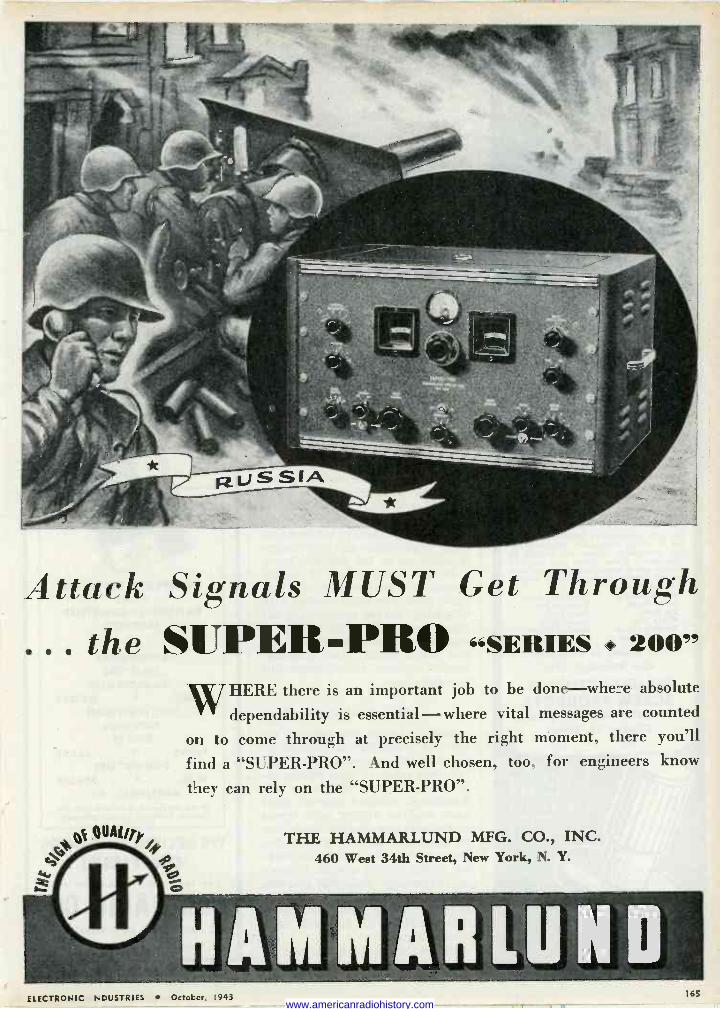
W
Attack Signals MUST Get Through . the SUPER-PRO SERIES 200"
WHERE there is an important job to be done-where absolute
dependability is essential - where vital messages are counted
on to come through at precisely the right moment, there you'll
find a "SUPER-PRO". And well chosen, too, for engineers know
they can rely on the "SUPER-PRO".
QUAI/ly
y '4:00 460 West 34th Street, New York, N. Y. O
oHAMMARLUND
THE HAMMARLUND MFG. CO., INC.
ELECTRONIC INDUSTRIES October, 1943 165 www.americanradiohistory.com
SPECIAL HEADS, special SiiOUL- DERS, special LENGTHS, special
TE-IREADS, special POINTS-made to your order-cold forged for economy of METALS, LABOR, TIME and MONEY.
1 Precision made the cold forged way -without loss of quality, torque, or tensile strength, and to the tolerances required. All supplementary operations, such as DRILLING, SLOTTING and KNURLING. All metals and finishes.
Your "Specials" May Be Our Stock Items
We have hundreds of SPECIAL fasten- ers in stock, originally designed for our customers, which we regard as "regulars." From these you may be able to select some that meet your own special requirements, without special tc.ol or die costs.
Plastic Inserts Shoulder Screws Collar Studs Terminal Pins Eye Bolts Hook Bolts Hinge Pins Spade Bolts Welding Screws Knurled Rivets Contact Points Captive Screws
It's Faster to Telephone Call WHitehall 4680
MANUFACTURERS SCREW PRODUCTS
268 WEST HUBBARD STREET Chicago 10, Illinois
Ask for Your Free Copy of the New STRONGHOLD SOCIAL SECURITY
CALCULATOR
while thin films, or layers corn prised of intimate mixtures of graphite and a non-conductor, ob- viously exhibit high resistance properties.
Light-sensitive cells Patents have been granted cov-
ering the use of "Aquadag" films in phototubes employing selenium and tellurium. The advantage of graphite over other electrode ma- terials in this application lies in its inability to combine with selen- ium to form a selenide. Since the electrical conductivity of selenides is greater than that of the element itself and inasmuch as the selenide formation is usually progressive, the sensitivity of a unit containing the graphite film does not decrease with age.
Graphite exhibits a peculiar af- finity for cesium, which property is also utilized in the manufacture of photoelectric cells and half -wave rectifiers.
When the latter type of tube is placed in operation the heat from the filament liberates the alkali, converting it into vapor in the re- gion between the electrodes. When the tube cools, the cesium is ad- sorbed by the graphite. It is stated that even if alkali metal has be- come affixed to the glass envelope, the metal gradually vaporizes at room temperature and is ultimate- ly taken up by the graphite layer.
In the manufacture of photo- electric cells the inclusion of a me- tallic plate previously treated with "Aquadag" makes unnecessary the usual practice of baking the cell at high temperatures to remove ex- cess alkali metal. The graphite - treated member accomplishes this by adsorption.
Electrical applications When colloidal graphite in the
form of "Aquadag" is painted on the insulating covering of arma- ture conductors of high voltage al- ternators, corona difficulties are eliminated. Similar aqueous paint when used on driving belts serves to dissipate any charges which may be generated by the friction be- tween air and the belting, the flex- ing of the belting and its slippage on the pulley. Colloidal graphite is effective for blackening the re- ceivers of thermopiles, particularly those designed for use with long infra -red rays.
Just as graphite films may be used as electrodes in vacuum de- vices. so may they be employed for
ACCEPT THIS
FREE 800 PAGE
RADIO - ELECTRONIC EQUIPMENT
CATALOG With Our
COMPLIMENTS!
AN INVALUABLE AID to PURCHASING AGENTS EXPEDITERS ENGINEERS
Write for it - today!
*
COMPLETE LISTINGS OF ALL
NATIONALLY -ADVERTISED PRODUCTS
CONDENSERS RESISTORS
TRANSFORMERS TUBES METERS
TEST EQUIPMENT SWITCHES
RELAYS PLUGS JACKS
CONNECTORS WIRE SOLDER
AMPLIFIERS, etc. Write our Dept. L-0 on company sta- tionery. Book will be sent promptly.
WE DELIVER the GOODS ON TIME!
New York's Oldest Radio Supply House
SUN RADIO CO. 212 FULTON ST., NEW YORK 7, N.Y. - Telephone BArclay 7.1840 -
166 ELECTRONIC INDUSTRIES October, 1943 www.americanradiohistory.com
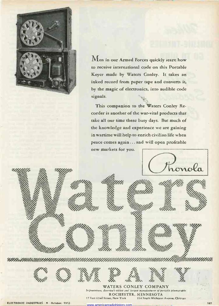
Men in our Armed Forces quickly learn how
to receive international code on this Portable
Keyer made by Waters Conley. It takes an
inked record from paper tape and converts it,
by the magic of electronics, into audible code
signals.
This companion to the `Waters Conley Re-
corder is another of the war -vital products that
take all our time these busy days. But much of
the knowledge and experience we are gaining
in wartime will help to enrich civilian life when
peace comes again ... and will open profitable
new markets for you.
WATERS CONLEY COMPANY In peacetime, America's oldest and largest manufacturer of portable phonographs
ROCHESTER, MINNESOTA 17 East 42nd Street, New York 224 South Michigan Avenue, Chicago
ELECTRONIC INDUSTRIES October, 19'3 167 www.americanradiohistory.com
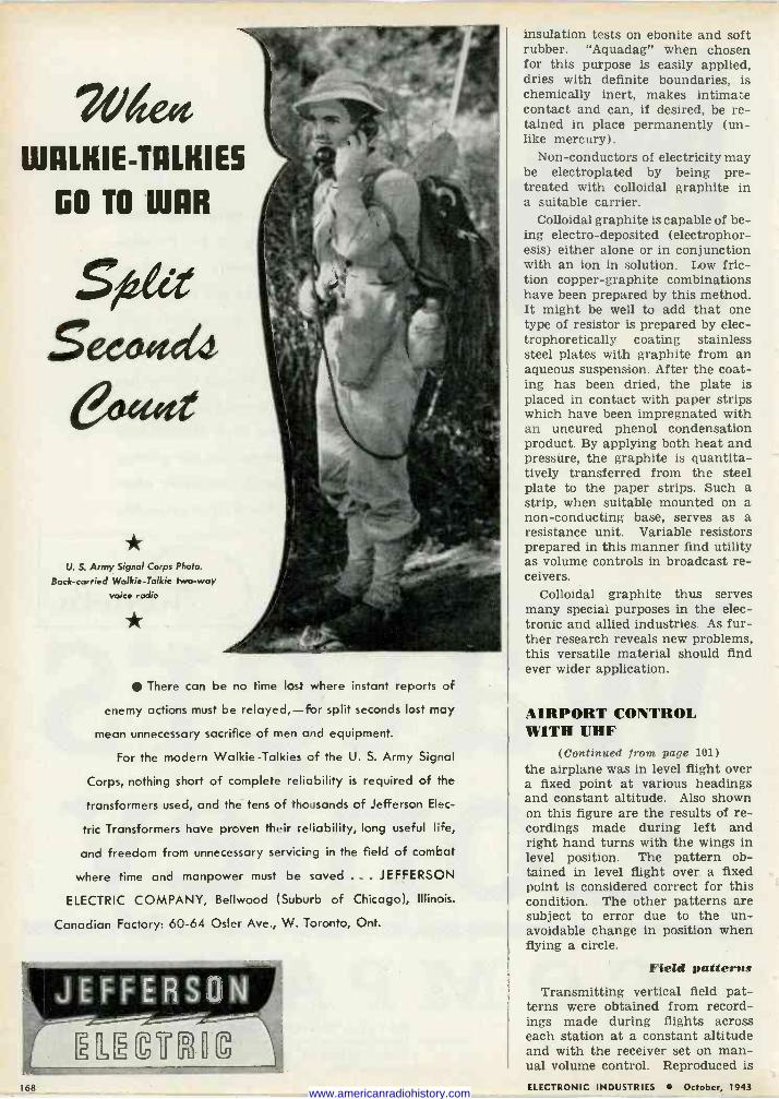
7Vdept WALKIE-TALKIES
GO TO WAR
Site Seeoff Ço«e
U. S. Army Signal Corps Photo.
Back -carried Walkie-Talkie two-way voice radio
There can be no time lost where instant reports of
enemy actions must be relayed,-for split seconds lost may
mean unnecessary sacrifice of men and equipment.
For the modern Walkie-Talkies of the U. S. Army Signal
Corps, nothing short of complete reliability is required of the
transformers used, and the tens of thousands of Jefferson Elec-
tric Transformers have proven their reliability, long useful He,
and freedom from unnecessary servicirg in the field of combat
where time and manpower must be saved . .. JEFFERSON
ELECTRIC COMPANY, Bellwood (Suburb of Chicago), Illinois.
Canadian Factory: 60-64 Oster Ave., W. Toronto, Ont.
insulation tests on ebonite and soft rubber. "Aquadag" when chosen for this purpose is easily applied, dries with definite boundaries, is chemically inert, makes intimate contact and can, if desired, be re- tained in place permanently (un- like mercury).
Non-conductors of electricity may be electroplated by being pre- treated with colloidal graphite in a suitable carrier.
Colloidal graphite is capable of be- ing electro -deposited (electrophor- esis) either alone or in conjunction with an ion in solution. Low fric- tion copper -graphite combinations have been prepared by this method. It might be well to add that one type of resistor is prepared by elec- trophoretically coating stainless steel plates with graphite from an aqueous suspension. After the coat- ing has been dried, the plate is placed in contact with paper strips which have been impregnated with an uncured phenol condensation product. By applying both heat and pressure, the graphite is quantita- tively transferred from the steel plate to the paper strips. Such a strip, when suitable mounted on a non -conducting base, serves as a resistance unit. Variable resistors prepared in this manner find utility as volume controls in broadcast re- ceivers.
Colloidal graphite thus serves many special purposes in the elec- tronic and allied industries. As fur- ther research reveals new problems, this versatile material should find ever wider application.
AIRPORT CONTROL WITH UHF
(Continued from page 101)
the airplane was in level flight over a fixed point at various headings and constant altitude. Also shown on this figure are the results of re- cordings made during left and right hand turns with the wings in level position. The pattern ob- tained in level flight over a fixed point is considered correct for this condition. The other patterns are subject to error due to the un- avoidable change in position when flying a circle.
Field patterns Transmitting vertical field pat-
terns were obtained from record- ings made during flights across each station at a constant altitude and with the receiver set on man- ual volume control. Reproduced is
168 ELECTRONIC INDUSTRIES October, 1943 www.americanradiohistory.com
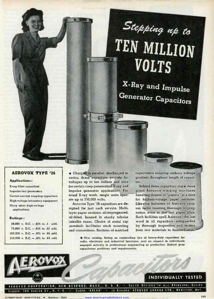
AEROVOX TYPE '26
Applications :
X-ray filter capacitors Impulse test generators Carrier -current coupling capacitors
High -voltage laboratory equipment
Many other high -vo tage applications
Ratings :
50,000 v. D.C.-.0)5 to .1 mid.
75,000 v. D.C. - .0)1 to .05 mfd.
100,000 v. D.C. - .001 to .05 mtd.
150,000 v. D.C. - .001 to .03 mid.
X -Ray and Impulse Generator Capacitors
Charged in parallel, discharged in series, these capacitors provide for ,oltages up to ten million and over 1 or certain seep -penetration X-ray and impulse generator applications. For usual X-ray work, single units oper- ate up to 150,000 volts.
Aerovo.c Type '26 capacitors are de- signed f x just such service. Multi- iayer paper sections, oil -impregnated, oil -filled, Loused in sturdy tubular oakeliie cases. Choice of metal cap terminals :acilitates stack mounting and connections. Sections of matched
capacitance insuring uniform voltage gradient throughout length of capaci- tor.
Behind these capacitors stand those giant Aerovox winding machines handling dozens of "papers" at a time for highest -voltage paper sections. Likewise batteries of Aerovox vacu- um tanks insuring thorough impreg- nation even to the last paper fibre. Such facilities spell Aerovox- the last word in oil capacitors safeguarded by thorough inspection and testing from raw materials to finished -units.'
New catalog, listing an outstanding line of heavy-duty capacitors for radio, electronic and industrial functions, sent on request to individuals engaged actively in professional engineering or production. Submit your capacitance problems and requirements.
INDIVIDUALLY TESTED
AEROVOX CORPORATION. NEW BEDFORD, MASS., U. S. A. SALES OFFICES IN ALL PRINCIPAL CITIES
Export: 100 VARICE ST N. Y. C. Cable ARLAB' In Canada: AEROVOX CANADA LTD., HAMILTON, ONT.
ri rrTonuir INnIJCTOIrC 1045 169 www.americanradiohistory.com
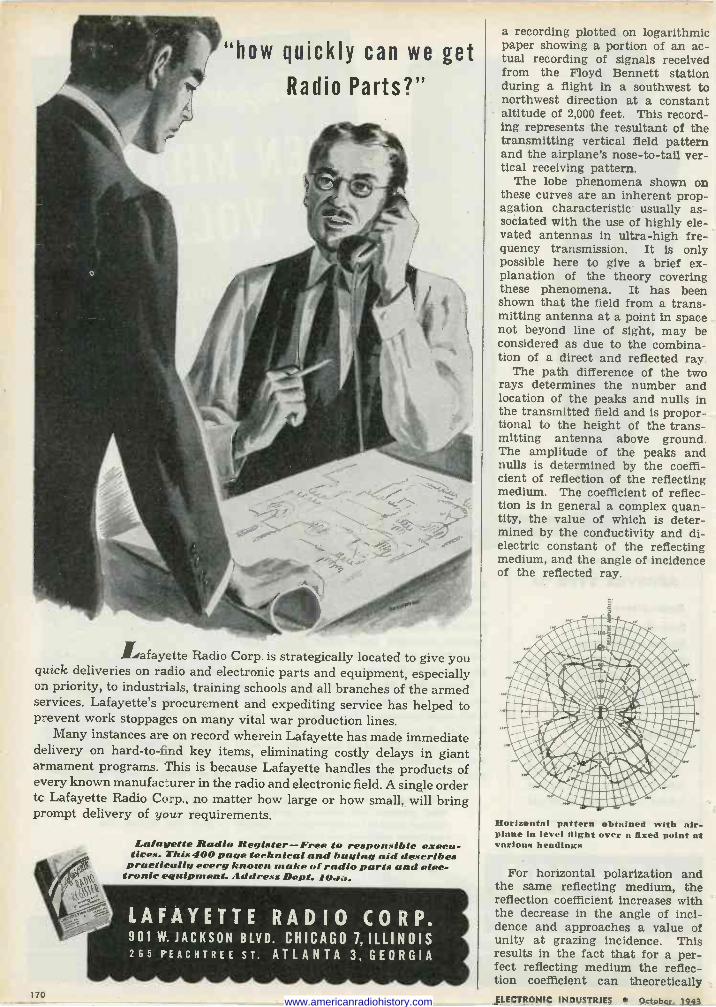
'how quickly can we get
Radio Parts?"
Lafayette Radio Corp. is strategically located to give you quick deliveries on radio and electronic parts and equipment, especially on priority, to industrials, training schools and all branches of the armed services. Lafayette's procurement and expediting service has helped to prevent work stoppages on many vital war production lines.
Many instances are on record wherein Lafayette has made immediate delivery on hard -to -find key items, eliminating costly delays in giant armament programs. This is because Lafayette handles the products of every known manufacturer in the radio and electronic field. A single order to Lafayette Radio Corp., no matter how large or how small, will bring prompt delivery of your requirements.
Lafayette Radio Register-Free to responsible execu- tives. This 400 page technical and buying aid describes practically every known make of radio parts and elec-
tronic equipment. Address Dept. 10.1.s.
LAFAYETTE RADIO CORP. 901 W. JACKSON BLVD. CHICAGO 7, ILLINOIS 265 PEACHTREE sr. ATLANTA 3, GEORGIA
170
a recording plotted on logarithmic paper showing a portion of an ac- tual recording of signals received from the Floyd Bennett station during a flight in a southwest to northwest direction at a constant altitude of 2,000 feet. This record- ing represents the resultant of the transmitting vertical field pattern and the airplane's nose -to -tail ver- tical receiving pattern.
The lobe phenomena shown on these curves are an inherent prop- agation characteristic usually as- sociated with the use of highly ele- vated antennas in ultra -high fre- quency transmission. It is only possible here to give a brief ex- planation of the theory covering these phenomena. It has been shown that the field from a trans- mitting antenna at a point in space not beyond line of sight, may be considered as due to the combina- tion of a direct and reflected ray.
The path difference of the two rays determines the number and location of the peaks and nulls in the transmitted field and is propor- tional to the height of the trans- mitting antenna above ground. The amplitude of the peaks and nulls is determined by the coeffi- cient of reflection of the reflecting medium. The coefficient of reflec- tion is in general a complex quan- tity, the value of which is deter- mined by the conductivity and di- electric constant of the reflecting medium, and the angle of incidence of the reflected ray.
Horizontal pattern obtained with air- plane in level flight over a fixed point at various headings
For horizontal polarization and the same reflecting medium, the reflection coefficient increases with the decrease in the angle of inci- dence and approaches a value of unity at grazing incidence. This results in the fact that for a per- fect reflecting medium the reflec- tion coefficient can theoretically ELECTRONIC INDUSTRIES October. 1943 www.americanradiohistory.com
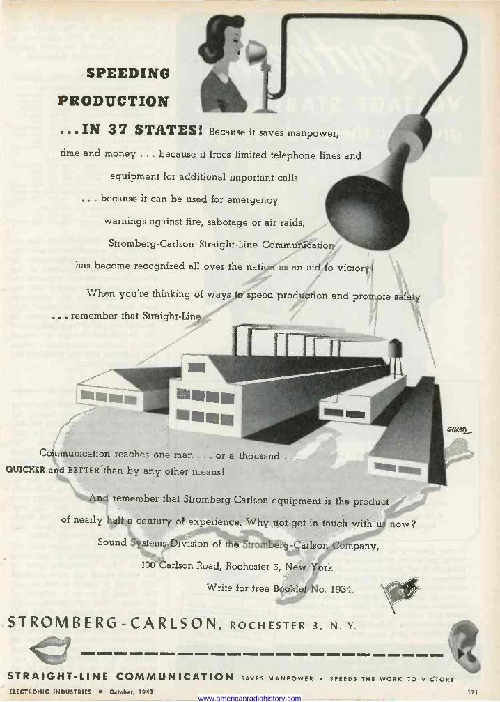
SPEEDING
PRODUCTION
...IN 3 7 STATES! Because it saves manpower,
time and money ... because it frees limited telephone lines and
equipment for additional important calls
.. because it can be used for emergency
warnings against fire, sabotage or air raids,
Stromberg -Carlson Straight -Line Communication
has become recognized all over the nation as an aid to victory!
When you're thinking of ways to speed production and promote safety
.. , remember that Straight -Line
Communication reaches one man ... or a thousand .. .
QUICKER and BETTER than by any other means!
And remember that Stromberg -Carlson equipment ís the product
of nearly half a century of experience. Why not get in touch with us now?
Sound Systems Division of the Stromberg -Carlson Company,
100 Carlson Road, Rochester 3, New York.
Write for free Booklet No. 1934.
STROMBERG-CARLSON, ROCHESTER 3, N.Y.
STRAIGHT-LINE COMMUNICATION SAVES MANPOWER SPEEDS THE WORK TO VICTORY
ELECTRONIC INDUSTRIES October, 1943 171 www.americanradiohistory.com
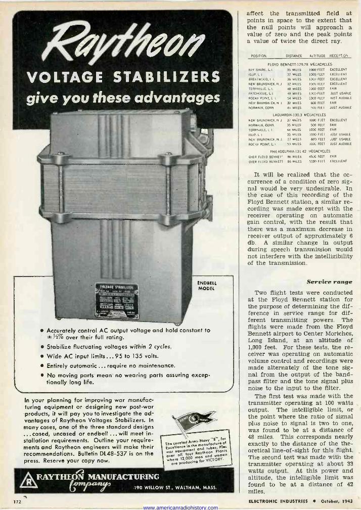
ENDBELL MODEL
Accurately control AC output voltage and hold constant to 12% over their full rating.
Stabilize fluctuating voltages within 2 cycles.
Wide AC input limits ... 95 to 135 volts.
Entirely automatic ... require no maintenance.
No moving parts mean no wearing parts assuring excep- tionally long life. 2
In your planning for improving war manufac- turing equipment or designing new post-war products, it will pay you to investigate the ad- vantages of Raytheon Voltages Stabilizers. In
many cases, one of the three standard designs ...cased, uncased or endbell ... will meet in- stallation requirements. Outline your require- ments and Raytheon engineers will make their recommendatiohs. Bulletin DL48-537 is on the press. Reserve your copy now.
The coveted ArmY-NavY for
EKcellence IO the modo tubé Res war equ,Pment Raytheon Plonts
whearere IZ,000 men and woVICTOR,Y.men
Orod ucing for over all four
RAYTHEON MANUFACTURING 190 WILLOW ST., WALTHAM, MASS.
affect the transmitted field at points in space to the extent that the null points will approach a value of zero and the peak points a value of twice the direct ray.
POSITION DISTANCE ALTITUDE RECEPTION
FLOYD BENNETT-129.
BAY SHORE. L.I. 35 MILES
ISLIP, L I 37 MILES
BRENTWOOD, L I.
NEW BRUNSWICK, N
TERRYVILLE, L L
PATCHOGUE, L. I
ROCKY POINT, L I.
NEW BRUNSWICK,N J
NORWALK, CONN
36 MILES
32 MILES
48 MILES
48 MILES
54 MILES
32 MILES
44 MILES
LAGUARDIA.130.3
NEW BRUNSWICK, N J 37 MILES
NORWALK, CONN. 35 MILES
TERRYVILLE, L. I. 44 MILES
ISLIP, L. I 35 MILES
NEW BRUNSWICK. N. J. 37 MILES
ROCKY POINT, L. I 50 MILES
78 MEGACYCLES
1000 FEET EXCELLENT
1000 FEET EXCELLENT
1000 FEET
1000 FEET
1000 FEET
1000 FEET
1000 FEET
600 FEET
500 FEET
MEGACYCLES
1000 FEET
500 FEET
1000 FEET
1000 FEET
600 FEET
1000 FEET
EXCELLENT
EXCELLENT
FAIR
JUST USABLE
JUST AUDIBLE
FAIR
JUST AUDIBLE
EXCELLENT
FAIR
FAIR
JUST USABLE
JUST USABLE
JUST AUDIBLE
PHILADELPHIA -131 42 MEGACYCLES
OVER FLOYD BENNETT 86 MILES 4500 FEET FAIR
OVER FLOYD BENNETT 86 MILES 5500 FEET EXCELLENT
It will be realized that the oc- currence of a condition of zero sig- nal would be very undesirable. In the case of this recording of the Floyd Bennett station, a similar re- cording was made except with the receiver operating on automatic gain control, with the result that there was a maximum decrease in receiver output of approximately 6 db. A similar change in output during speech transmission would not interfere with the intelligibility of the transmission.
Service range Two flight tests were conducted
at the Floyd Bennett station for the purpose of determining the dif- ference in service range for dif- ferent transmitting powers. The flights were made from the Floyd Bennett airport to Center Moriches, Long Island, at an altitude of 1,000 feet. For these tests, the re- ceiver was operating on automatic volume control and recordings were made alternately of the tone sig- nal from the output of the band- pass filter and the tone signal plus noise to the input to the filter.
The first test was made with the transmitter operating at 100 watts output. The intelligible limit, or the point where the ratio of signal plus noise to signal is two to one, was found to be at a distance of 48 miles. This corresponds nearly exactly to the distance of the the- oretical line -of -sight for this flight. The second test was made with the transmitter operating at about 33 watts output. At this power and altitude, the intelligible limit was found to be at a distance of 42 miles.
172 ILICTRONIC INDUSTRIES October, 1943
www.americanradiohistory.com
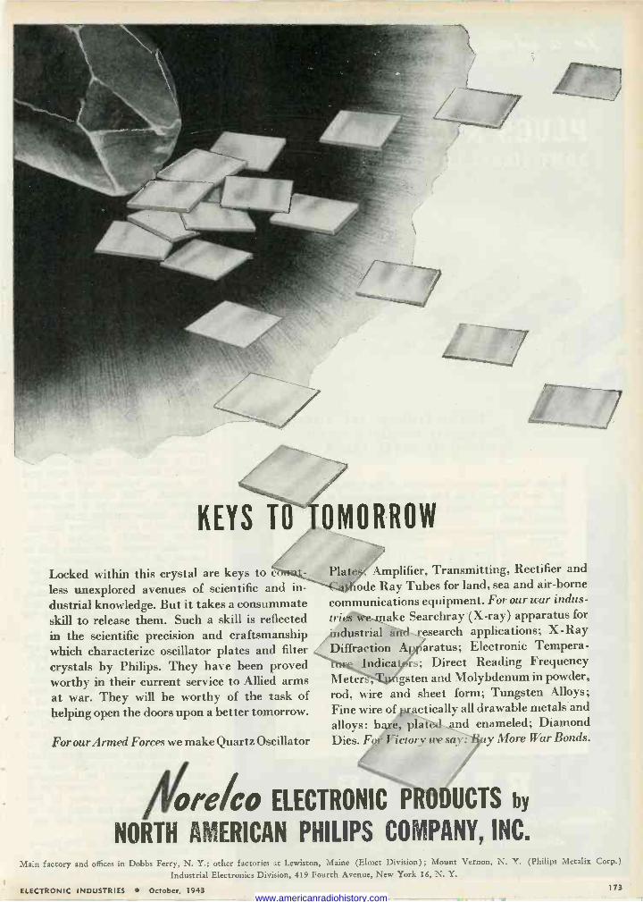
KEYS TO
Locked within this crystal are keys to c?>rri.it
less unexplored avenues of scientific and in-
dustrial knowledge. But it takes a consummate skill to release them. Such a skill is reflected in the scientific precision and craftsmanship which characterize oscillator plates and filter crystals by Philips. They have been proved worthy in their current service to Allied arms at war. They will be worthy of the task of helping open the doors upon a better tomorrow.
For our Armed Forces we make Quartz Oscillator
OMORROW
l'l a t es,, Amplifier, Transmitting, Rectifier and ``-4-4hode Ray Tubes for land, sea and air -borne
communications equipment. For our war indus- trifo,.make Searchray'(X-ray) apparatus for
/industrial ùnd esearch applications; X -Ray I )iffraction ;1 aratus; Electronic Tempera- nr. l ndicat; 'rs; Direct Reading Frequency
Meters, ' ' gsten and Molybdenum in powder, rod, wire and sheet form; Tungsten Alloys;
Fine wire of actically all drawable metals -and
alloys: bee plan and enameled; Diamond Dies. For Victory tre .sir.: P y More War Bonds.
óre%o ELECTRONIC PRODUCTS by
NORTH AMERICAN PHILIPS COMPANY, INC.
Main factory and offices in Dobbs Ferry, N. Y.; other factories at Lewiston, Maine (Elmet Division) ; Mount Vernon, N. Y. (Philips Metalia Corp.)
Industrial Electronics Division, 419 Fourth Avenue, New York 16, N. Y.
ELECTRONIC INDUSTRIES October, 1943 173 www.americanradiohistory.com
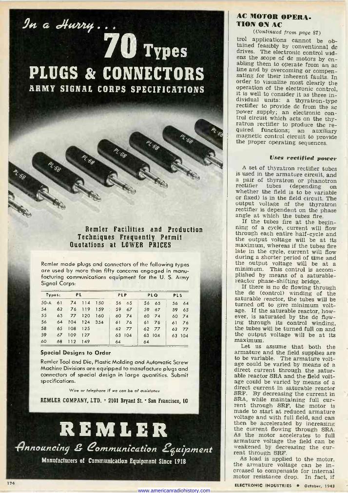
70 Types PLUGS 8z CONNECTORS ARMY SIGNAL CORPS SPECIFICATIONS
Bernier Facilities and Production Techniques Frequently Permit
Quotations at LOWER PRICES
Remler made plugs and connectors of the following types are used by more than fifty concerns engaged in manu- facturing communications equipment for the U. S. Army Signal Corps:
Types: PL PLP PLQ PLS
50-A 61 74 114 150 56 65 56 65 56 64 54 62 76 119 159 59 67 59 67 59 65 55 63 77 120 160 60 74 60 74 60 74 56 64 104 124 354 61 76 61 76 61 76 58 65 108 125 62 77 62 77 62 77 59 67 109 127 63 104 63 104 63 104 60 68 112 149 64 64
Special Designs to Order Remler Tool and Die, Plastic Molding and Automatic Screw Machine Divisions are equipped to manufacture plugs and connectors of special design in large quantities. Submit specifications.
Wire or telephone if we can be of assistance
REMLER COMPANY, LTD. 2101 Bryant St. San Francisco, 10
REMLER - renouncing. S eommunication feuiftment
Manufacturers of Communication Equipment Since 1918
174
AC MOTOR OPERA- TION ON AC
(Continued front page 87) trol applications cannot be ob- tained feasibly by conventional do drives. The electronic control wid- ens the scope of do motors by en- abling them to operate from an ac line and by overcoming or compen- sating for their inherent faults. In order to visualize most clearly the operation of the electronic control, it is well to consider it as three in- dividual units: a thyratron -type rectifier to provide do from the ac power supply; an electronic con- trol circuit which acts on the thy- ratron rectifier to produce the re- quired functions; an auxiliary magnetic control circuit to provide the proper operating sequences.
Uses rectified power A set of thyratron rectifier tubes
is used in the armature circuit, and a pair of thyratron or phanotron rectifier tubes (depending on whether the field is to be variable or fixed) is in the field circuit. The output voltage of the thyratron rectifier is dependent on the phase angle at which the tubes fire.
If the tubes fire at the begin- ning of a cycle, current will flow through each entire half -cycle and the output voltage will be at its maximum, whereas if the tubes fire late in the cycle, current will flow during a shorter period of time and the output voltage will be at a minimum. This control is accom- plished by means of a saturable - reactor phase -shifting bridge.
If there is no dc flowing through the dc (control) winding of the saturable reactor, the tubes will be turned off to give minimum volt- age. If the saturable reactor, how- ever, is saturated by the dc flow- ing through its control winding, the tubes will be turned full on and the output voltage will be at its maximum.
Let us assume that both the armature and the field supplies are to be variable. The armature volt- age could be varied by means of a direct current through the satur- able reactor SRA and the field volt- age could be varied by means of a direct current in saturable reactor SRF. By decreasing the current in SRA, while maintaining full cur- rent through SRF, the motor is made to start at reduced armature voltage and with full field, and can then be accelerated by increasing the current flowing through SRA. As the motor accelerates to full armature voltage the field can be weakened by decreasing the cur- rent through SRF.
As load is applied to the motor, the armature voltage can be in- creased to compensate for internal motor resistance drop. In fact, if ELECTRONIC INDUSTRIES October, 1943
www.americanradiohistory.com
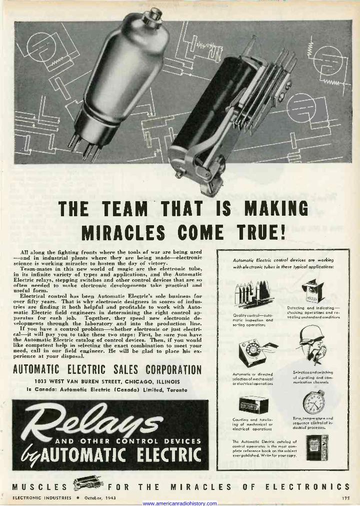
THE TEAM THAT IS MAKING
MIRACLES COME TRUE! All along the fighting fronts where the tools of war are being used
-and in industrial plants where they are being made-electronic science is working miracles to hasten the day off victory.
Team-mates in this new world of magic are the electronic tube, in its infinite variety of types and applications, and the Automatic Electric relays, stepping switches and other control devices that are so often needed to make electronic developments take practical and useful form.
Electrical control has been Automatic Electric's sole business for over fifty years. That is why electronic designers in scores of indus- tries are finding it both helpful and profitable to work with Auto- matic Electric field engineers in determining the right control ap- paratus for each job. Together, they speed new electronic de- velopments through the laboratory and into the production line.
If you have a control problem-whether electronic or just electri- cal-it will pay you to take these two steps: First, be sure you have the Automatic Electric catalog of control devices. Then, if you would like competent help in selecting the exact combination to meet your need, call in our field engineer. Ile will be glad to place his ex- perience at your disposal.
AUTOMATIC ELECTRIC SALES CORPORATION 1033 WEST VAN BUREN STREET, CHICAGO, ILLINOIS
In Canada: Automatic Electric (Canada) Limited, Toronto
geaes AND OTHER CONTROL DEVICES
69AUTONIATIC ELECTRIC
Automatic Electric control devices are working
with electronic tubes in these typical applications:
Quality control-auto- matic inspection and sorting operations
Automatic or directed selection of mechanical or electrical operations
Counting and totaliz- ing of mechanical or electrical operations
Detecting and indicating - checking operations and re- vealing unstandard conditions
Selection and switching of signaling and com- munication channels
Time, temperature and sequence control of in- dustrial processes.
The Automatic Electric catalog of control apparatus is the most com- plete reference book on the subject ever published. Write for your copy.
MUSCLESFOR THE MIRACLES OF ELECTRONICS ELECTRONIC INDUSTRIES OctoLer, 1943 175
www.americanradiohistory.com
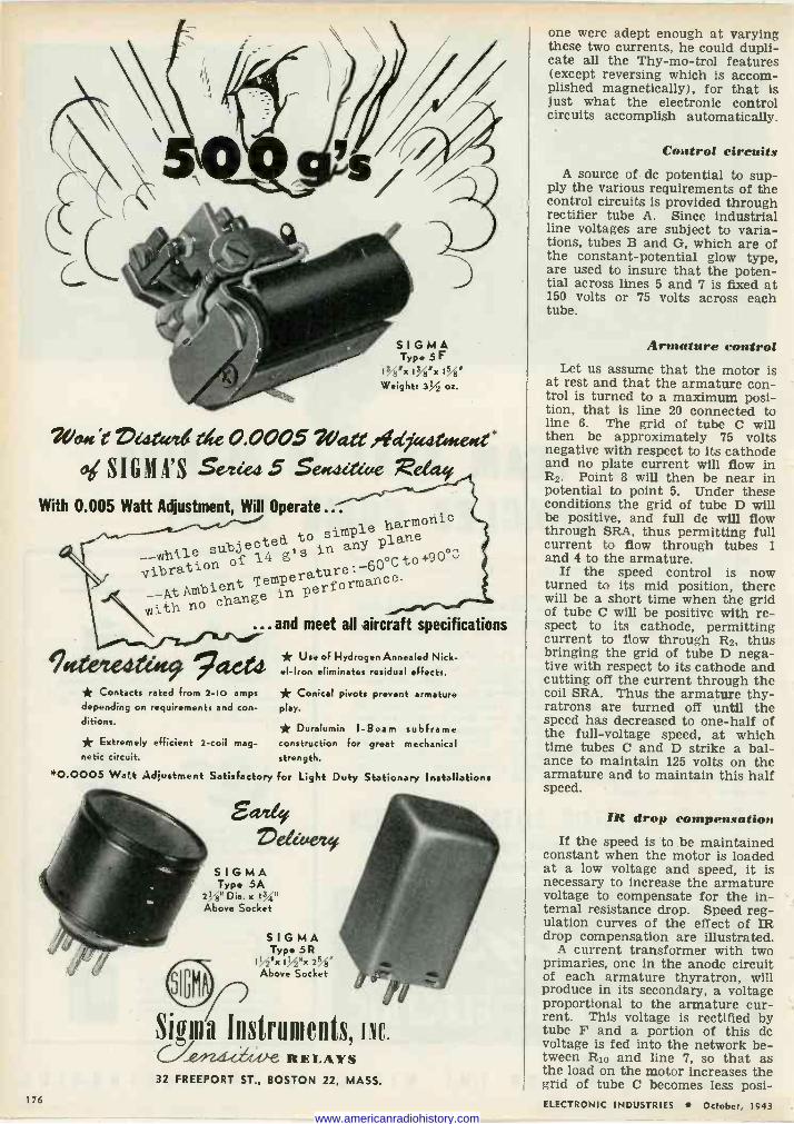
SIGMA Type 5F
IWx I/x I Weight: 3% oz.
?ea«? z,e124444 de 0.0005 Watt Ateatyt.e.ct' o Min G M A' S Seeced 5 Se.cdctecie
With 0.005 Watt Adjustment, Will Operate...
simple harmonic subjected,toin any
plane
vibration o f 14 g s ° +90°L tion erature :-60 C
to ibra __At Ambient Temp erformance With no change
in p
...and meet all aircraft specifications
Totemedeüte, 9act4 * Contacts rated from 2 -IO amps depending on requirements and con- ditions.
* Extremely efficient 2 -coil mag- netic circuit.
* Use of Hydrogen Annealed Nick- el -Iron eliminates residual effects.
* Conical pivots prevent armature play.
* Duralumin I -Beam subframe construction for great mechanical strength.
*0.0005 Watt rtdiustment Satisfactory for Light Duty Stationary Installations
SI
54419 VeQúeite,
SIGMA Type SA
2!ti" Dia. x Above Socket
GMA
SIGMA Type SR
Isx Isx 2V8" Above Socket
Sions Instruments, Inc. V RELAYS 32 FREEPORT ST., BOSTON 22, MASS.
176
one were adept enough at varying these two currents, he could dupli- cate all the Thy-mo-trol features (except reversing which is accom- plished magnetically), for that is just what the electronic control circuits accomplish automatically.
Control circuits A source of dc potential to sup-
ply the various requirements of the control circuits is provided through rectifier tube A. Since industrial line voltages are subject to varia- tions, tubes B and G, which are of the constant -potential glow type, are used to insure that the poten- tial across lines 5 and 7 is fixed at 150 volts or 75 volts across each tube.
Armature control Let us assume that the motor is
at rest and that the armature con- trol is turned to a maximum posi- tion, that is line 20 connected to line 6. The grid of tube C will then be approximately 75 volts negative with respect to its cathode and no plate current will flow in R2. Point 8 will then be near in potential to point 5. Under these conditions the grid of tube D will be positive, and full do will flow through SRA, thus permitting full current to flow through tubes 1 and 4 to the armature.
If the speed control is now turned to its mid position, there will be a short time when the grid of tube C will be positive with re- spect to its cathode, permitting current to flow through R2, thus bringing the grid of tube D nega- tive with respect to its cathode and cutting off the current through the coil SRA. Thus the armature thy- ratrons are turned off until the speed has decreased to one-half of the full -voltage speed, at which time tubes C and D strike a bal- ance to maintain 125 volts on the armature and to maintain this half speed.
IR drop compensation If the speed is to be maintained
constant when the motor is loaded at a low voltage and speed, it is necessary to increase the armature voltage to compensate for the in- ternal resistance drop. Speed reg- ulation curves of the effect of IR drop compensation are illustrated.
A current transformer with two primaries, one in the anode circuit of each armature thyratron, will produce in its secondary, a voltage proportional to the armature cur- rent. This voltage is rectified by tube F and a portion of this dc voltage is fed into the network be- tween R10 and line 7, so that as the load on the motor increases the grid of tube C becomes less posi - ELECTRONIC INDUSTRIES October, 1943
www.americanradiohistory.com
OG e
"-~-;
I,VsAp
Fc4D DEPARTT EN
by 1`he PLASTICS
R1VpLDgmen R1 s RqRT pedfi
ttp piece
large specialize //O R COrd'ng to difficult. nd small in helping
both1T m g the f'clt Prob !! pa he ACCURATE 1 problems
in ply Solve (heir SPECIAC p;CS1AGN1 N1NG _
JNT a stiCs
-..
GN ~ QUALITY iCATE MOLDING
ii ry,
Ce,a%,e ta,rej-e-re.n,e-e r-u..ti.n-9 tM-t,th «.t{ irte-[.t.i-+`ie
ARNOLD BRILHART CO M? A N Y ° 435 MIDDLENECK ROAü ° GREAT NECK,NY. " /we GREAT NECK 405'4
ELECTRONIC INDUSTRIES October, 1943 177
www.americanradiohistory.com
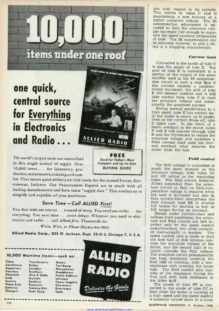
I ---r- .. ...,.,. ._.t
one quick, central source
for Everything
in Electronics
and Radio ... The world's largest stocks are centralized in this single arsenal of supply. Over 10,000 items ... for laboratory, pro- duction, maintenance, training and com- bat. That means quick delivery on vital needs for the Armed Forces, Gov ernment, Industry. Our Procurement Experts are in touch with al leading manufacturers and have latest "supply data." This enables us to simplify and expedite all your purchases.
Save Time-Call ALLIED First! You deal with one source ... instead of many. You send one order ... for everything. You save time ... avert delays. Whatever you need in elec- tronics and radio ... call Allied first. Thousands do.
Write, Wire, or Phone Haymarket 6800.
Allied Radio Corp., 833 W. Jackson, Dept. 32-K-3, Chicago 7, U.S.A.
FREE Send for Today's Most
Complete and Up -To-Date BUYING GUIDE
10,000 Wartime Items-such as: Tubes Transformers Condensers Relays Capacitors Switches Resistors Rectifiers Rheostats Wire & Cable Coils Crystals Sockets Speakers Photo Cells Receivers Batteries Training Kits Chargers Code Equip.
178
Meters Test Equip. Microphones Headphones Public Address Intercom Power Supplies Converters Generators Tools
ALLIED RADIO
ve4«,e-cemetil
mIBMIMIMIM
tive with respect to its cathode. This results in tubes C and D maintaining a new balance at a higher armature voltage. The IR compensation adjustment is ad- justed so that the armature volt- age increases just enough to main- tain the speed constant irrespective of load. The IR compensation can be adjusted, however, to give a ris- ing or a dropping characteristic.
Current limit Connected to the anode of tube C
is also the anode of tube E. The grid of tube E is connected to a portion of the output of the same rectifier used in the IR compensa- tion circuit in such a way that if the current exceeds a predeter- mined maximum, the grid of tube E will become positive and it will take control from tube C to limit the armature voltage and conse- quently the armature current.
During normal acceleration to a high speed, tube E has control un- til the motor is nearly up to speed; then as the current drops off, tube C takes over. In the event of a heavy overload on the motor, tubes F and E will operate through tube D and the thyratrons to reduce the armature voltage and maintain a fixed current limit until the ther- mal overload relay removes the motor from the line.
Field control The field voltage is controlled in
much the same manner as the armature voltage, with tubes CC and DD acting as the regulating tubes. The field circuit, however, differs somewhat from the arma- ture circuit in that no field -com- pensation voltage is required when the load is increased and also in that current -limit strengthens the field through tube EE to provide full torque for starting as well as full torque during an overload.
Except under current -limit and voltage -limit conditions, the arma- ture and field circuits are tied to- gether only by the speed control potentiometers, two units connect- ed mechanically in tandem. The speed control unit is made so that the first half of dial rotation con- trols the armature voltage of the motor, and the second half of ro- tation controls the field voltage. The armature circuit potentiometer has high resistance covering the first half of rotation, with a low - resistance unit covering the latter half. The field control unit con- sists of low resistance during the first half with high resistance in the latter half.
The anode of tube FF is con- nected to the anode of tube CC so that when the motor is running at a high speed and the speed control is suddenly turned down to a lower ELECTRONIC INDUSTRIES October, 1943
www.americanradiohistory.com

Even the Big Inch Needs IRC RESISTORS Vital arteries of supply in this mechanized war are America's pipelines. To maintain capacity flow, sludge and gummy deposits must be cleaned out at intervals. For this purpose a screw -type
ANOTHER l lj C DEVELOPMENT
scraper propelled by the oil pressure is employed. When occasionally the scraper becomes stuck and plugs the line, the point of stoppage must be located to release the flowing oil. But where-and how?
With the use of the Geiger - Mueller Counter, hours-and sometimes days - of search are saved. Modern scrapers contain radio -active metal which con - 1
ARIABLE %ES'S
INTERNATIONAL RESISTANCE COMPANY
stantly emits an impulse message. When trouble occurs, these signals are picked up by the Counter, as the line is checked. At the point of greatest intensity the pipeline is tapped and the obstruction cleared away.
IRC engineering ingenuity plays an important part in the functioning of Geiger -Mueller Counters. Many specially designed IRC resistors and controls are employed in their carefully ad- justed circuits.
If you have a design or engineering problem involving resistance units and you
P
ER 'eh
1,y not come to Resistor headquarters at IRC? We make more types of resistors, in more sizes, for more applications than any other manu- facturer in the world.,
425 N. BROAD STREET PHILADELPHIA 8, PA.
ELECTRONIC INDUSTR.''ES Octobeq 1543 179 www.americanradiohistory.com
BEST TOOLS KEPT HERE Some of America's most famous companies will tell you that we have exceptionally excellent facilities for pre- cision manufacturing. That's right! But, we maintain that our very best tools are 54 years of "Know What" ;and "Know How."
When you, too, need Metal Fabrication: Precision 'Machine Work: Electrical and Mechanical Assembly- i"Let Lewyt Do It." Our carefully engineered methods and closely coordinated production controls enable you to shoulder us with the entire production responsibility for a complete product-or a single part. This "Pack-
` aged Production" may deliver the best answer to your war production problems and peacetime plans. Prior commitments permitting!
CO 6 0 B R O A D WA Y , B R O O K LY N, N. Y.
speed, the grid of tube FF becomes positive and takes control should the armature voltage become ex- cessive under the full -field condi- tion. This tube prevents full field being applied suddenly when the speed control is turned from top speed to low speed and thus pre- vents the motor from generating an excessive armature voltage.
Pre -conditioning on starting
When starting, it is desirable to have full field with reduced arma- ture voltage to provide rated, or slightly above rated torque. Aux- iliary contacts are provided on the line contactor to strengthen the field and to take care of this re- duction. Before the regulator tubes have a chance to assume control, the circuit is thus prepared with full - field and reduced - armature voltage, and as the current -limit circuit takes control, the effect of the "pre -conditioning" circuit grad- ually disappears.
In addition to the electronic fea- tures, the following magnetic con- trol devices are included: a cathode protective timer to insure suffi- cient heating of the thyratron tubes; a field -loss relay to shut the equipment down if a failure occurs in any part of the field circuit; an overload relay to protect the motor against sustained overloads; and anode fuses to protect the equip- ment during short-circuits. The necessary control devices to pro- vide starting, stopping, conven- tional dynamic braking, reversing, jogging, or any special operating sequence can be added to suit the requirements of specific applica- tions.
Features such as quick slowdown for high -inertia loads, follow-up between one motor and another, pilot -generator feedback for ex- tremely precise speed regulation, and simplified circuits for frac- tional horsepower motors are only a few of the flexible features of Thy-mo-trol not mentioned in this article but representing variations in design applicable to special drives.
POSITIVE GRID OSCILLATORS
(Continued from page 78)
may have more than one possible mode of operation. Actually, as was noted by Scheibe and others, there may be several modes, all subject to coincidental stimulation. These individuals observed that their os- cillators produced, under certain conditions, coexistent waves whose frequencies were nearly integral multiples of that of the normal wave. Because of the shortness of these secondary oscillations Pota- penko5 denominated them "dwarf waves," and investigated several
180 ELECTRONIC INDUSTRIES October, 1943 www.americanradiohistory.com
CHARMED/ SY/RF e
SGT K/L DAY CA/die ZEE --
Echophone Model EC -1 (Illustrated) a compact communications receiver
with every necessary feature for good reception.
Covers from 550 kc. to 30 mc. on three bands. Elec-
trical bandspread on all bands. Six tubes. Self-
contained speaker. Operates on 115-125 volts AC
or DC.
ECHOPHONE RADIO CO., 201 EAST 26th ST., CHICAGO, ILLINOIS
ELECTRONIC INDUSTRIES October, 1943 181
www.americanradiohistory.com
Type "C" D.C. G for Permanent Magnet Field, ball -bearing equipped: 13/4" outside diameter, 3s/e" in
length ... weighs 16 ounces.
THE
ALL-IMPORTANT
PROMPT DELIVERY Elinco fractional - h.p. motors and gen- erators combine compactness and small size with utmost precision and accuracy, the result of long experience and ex- treme manufacturing care and testing
plus adequate production to assure the most prompt delivery possible.
Type "B" A.C. G for Permanent Magnet Field wound for one, two or three phase A.C. Ball -bearing equipped; flange or base mounted. 21/4" outside diam- eter ... weighs 16 ounces.
L'/J++ca Can supply quantity production on standard items, or produce experimental or production machines built to your own specifications.
ELECTRIC INDICATOR CO. STAMFORD U.S.A. CONN.
orders thereof. While it might ap- pear that these and harmonics are one and the same, such is not the case. Dwarf waves differ from overtones in that the former are completely independent of normal waves, this independence being ex- perimentally demonstrable.
Optimum tube structures Included among the observations
of Barkhausen and Kurz was one stating that not all forms of tri- odes are suitable for use as oscilla- tion generators. They came to this conclusion after making numerous experiments which showed that, of various tube types, only certain of those tubes having symmetrically arranged, cylindrical electrodes would function in an oscillator capacity. Analysis of structures of those particular cylindrical elec- trode triodes found usable gave rise to the inference that they dif- fered from unusable ones in having elements which brought about es- tablishment of regular and well balanced electric fields through- out the interelectrode space.
To these general observations were added later some of a more concrete nature by Sahanek6. From theoretical studies of the ef- fects associated with variations in ratio of plate radius to that of the j
grid, and subsequent experimental studies confirming the theoretical, he concluded that for a tube to be well adapted to positive grid oscil- lator circuits it should have the ratio of its plate radius to that of its grid restricted to the limits
2.0 < r2 < 5.0 rl
Here r2 is the radius of the plate electrode and r1 is the radius of the grid. According to a second conclu- sion drawn by Sahanek it would be possible for a tube whose grid were somewhat eccentric with respect to the plate still to act as an oscilla- tor provided a certain limiting ec- centricity were not exceeded.
A second factor relating to os- cillator tubes that has practical significance is the gas pressure in- side tube envelopes. Being propor- tional to the number of gas mole- cules therein it necessarily provides a measure of the molecular inter- ference with electronic movements. Just how such interference is mani- fested in oscillatory changes has been made the subject of numerous investigations among the earliest of which were perhaps those of GrechowaT, Kapzovs, and Rind- fleisch9.
All three investigators, though working with pressures due to dif- ferent elements (Grechowa and Rindfleisch concerned themselves mainly with residual gases, whereas Kapzov's study involved the use of mercury vapor), found both the
,A APOLOGY «í a PROMEf
Through Uncontrollable
Circumstances ... Our Catalog was Delayed
Our sincere apologies ... we've tried to be patient, and hope you have too, but it is now really ready for mailing, after several months' delay in preparation. It's NEWER, more VALUABLE, and more INTERESTING.
We promise you a BETTER book, however, because the interim has al- lowed us to include many new items. The catalog is packed full of helpful, up-to-the-minute information on tim- ing motors for use in Automatic Reset Timers-Time Delay Relays-Vacuum Tube Circuit Controls, etc.
1 Complete information on Timing Motors by The Originators of
The Timing Motor
Send TODAY forYour Copy! fleadgaarters
for
a d 0 MANUFACTURING COMPANY
* INCORPORATED *
ean.etediciet 182 ELECTRONIC INDUSTRIES October, 1943
www.americanradiohistory.com
PERMANENT MAGNETS MAY DO IT BETTER
When Will "The Age Of Electronics" Begin?
THE answer, obviously, is when the war is
won, for only then can America's scientists
and engineers-now concentrating on elec-
tronics for war-devote all of their efforts to
applying electronics to peacetime uses. But
because it's their nature to prepare for the
unpredictable future, many of them, despite
heavy working schedules, are already thinking
about post-war products utilizing their elec-
tronic discoveries.
If you are one of these men, working on war-
time or post-war problems, we'd like to suggest
that you consider incorporating the principle
of the permanent magnet, and that you ask us
for any information you need. Because we've
specialized in this one field for 33 years, we've
been able to design and produce permanent magnets that have improved the functions and
increased the uses of many vital electronic de-
vices, as well as countless other important prod-
ucts. To these we made a valuable engineering contribution. To you we offer the same service.
Though our plant (the nation's largest spe-
cializing in the making of permanent magnets)
is devoted to war orders, our engineers will be
glad to consult with you and give your problems
the benefit of their unusual experience.
Write for the address of our office
nearest you and a copy of our 30 - page "Permanent Magnet Manual".
Let's speed victory these two ways: by more war production and by buying more War Bonds! e INDIANA STEEL PRODUCTS
Compawy * SPECIALISTSIN PERMANENT MAGNETS SINCE 1 9 1 0
6 NORTH MICHIGAN AVENUE CHICAGO 2, ILLINOIS
ELECTRONIC INDUSTRIES October, 1943 183 www.americanradiohistory.com
SLIDE RULE OR
SCREWDRIVER \ e
... which will YOU be
using 2 years from now?
CREI OFFERS A PROVEN PLAN OF PERSONAL ADVANCEMENT FOR PRO- FESSIONAL RADIOMEN WHO WANT A SECURE PLACE FOR THEMSELVES IN THE POSTWAR RADIO -ELECTRONIC FIELD.
Thousands of new men have joined the ranks of the radio industry for the dura- tion. But after the war, even more thou- sands will return from the armed forces. War production will settle down to sup- plying civilian needs. Where will you fit into this picture?
If you are wise, you will look ahead and prepare for the good -paying engineering positions in radio -electronics and indus- trial electronics. Every man in radio to- day has the opportunity to see the amaz- ing developments that are taking place, as well as the unlimited opportunities available to men with modern technical training.
CREI can help you prepare by providing you with a proven program of home study training that will increase your technical ability and equip you to advance to the better -paying positions that offer se- curity and opportunity. The facts about CREI and what it can do for you are printed in a 32 -page booklet. It is well worth your reading. Send for it today.
WRITE FOR FREE 32 -PAGE BOOKLET
If you have had professional radio experience and want to make more money-let us prove to you we have something you need to qualify for a better radio Job. To help us intel- ligently answer your inquiry - PLEASE STATE BRIEFLY YOUR BACKGROUND OF EXPERIENCE, EDUCATION AND PRESENT POSITION.
CAPITOL RADIO ENGINEERING INSTITUTE Home Study Courses in Practical Radio -Electronics
Engineering for Professional Self -Improvement
Dept. EI -10, 3224 -16th Street, N. W. _
WASHINGTON 10, D. C. Contractors to U. S. Signal Corps -17. S. Navy-
U. S. Coast Guard Producers of Well -trained Technical Radiomen for Industry
wavelength and the oscillation in- tensity to be affected by such in- ternal pressures of tubes.
In the case of Grechowa's work, for example, noteworthy changes in these two quantities were produced by pressures ranging from 5.0 x 10⁻⁸ mm Hg, up to 1.0 x 10⁻⁴ mm Hg. At a pressure of about 1.0 x 10⁻³ mm Hg a disappearance of the oscilla- tions took place. Rindfleisch, again, in working toward the higher pres- sures observed that the starting point of oscillations was inclined to move to lower grid potentials, yet when pressures in excess of 5.0 x 10⁻⁴ mm Hg were reached all such tendencies likewise vanished.
Rindfleisch reported further that the presence of gas in a tube in- variably leads to a lengthening of the waves produced. So far as os- cillation intensities are concerned he pointed out, too, that maximum power is developed by tubes having high vacua, although pressures up to 5.0 x 10⁻⁵ mm Hg caused no ap- preciable diminution therein.
Grateful acknowledgment is made for the aid given to the writer by various members of the Physics De- partment staff of Iowa State College, especially Drs. P. H. Carr and J. W. Woodrow and Mr. L. E. Pinney, in the conduct of an experimental investiga- tion from which were drawn the data underlying the illustrations presented herein.
'Barkhausen, H. and Kurz, K. Die kurzesten mit Vacuumrohren herstellbaren Wellen. Physi- kalische Zeitschrift. 21: 1-6. 1920.
'Scheibe, A. Untersuchungen uber die Erzeu- gung sehr kleiner Wellen mit Gluhkathoden- rohren nach Barkhausen und Kurz. Annalen der Physik. 73: 54-88. 1924.
°Gill, E. W. B. and Morrell, J. H. Short electric waves obtained by valves. Philosophical Magazine. 44: 161-178. 1922.
'Llewellyn, F. B. The Barkhausen oscilla- tor. Bell Laboratories Record. 13: 354-358. 1935.
°Potapenko, G. Ultra -short electromagnetic waves. Physical Review. 39: 625-665. 1932.
°Sahanek, J. Theorie der Erzeugung von sehr kurzen elektro-magnetischen Wellen mit- tels Elektronenrohren. Physikalische Zeitschrift. 26: 368-376. 1925.
'Grechowa, M. T. Ein Electronenrohren-Gen- erator kurzer elektrischer Wellen. Zeitschrift fur Physik. 35: 50-58. 1926.
'Kapzov, N. Uber die kurzwelligen Schwin- gungen von Quecksilberdampf enthaltenden Elektronenrohren. Zeitschrift fur Physik. 35: 129-154. 1926.
°Rindfleisch, H. Uber die Einfluss von Gasen auf Barkausenschwingungen. Annalen der Phy- sik. 14: 273-298. 1932.
PRECISION INTERVAL TIMER
(Continued from page 95)
operation is needed, the internal balance of the circuit is such that the inaccuracy resulting from op- eration before stabilization does not exceed ±8 per cent of dial reading. A maximum error of less than 5 per cent after stabilization means that this timer must handle intervals correct within a few milli- seconds under normal conditions.
The RA -1308-S precision timer is designed around the principle of the resistance -capacitance oscilla -
LABORATORY
STAN DARDS
Standard Signal Generators
Square Wave Generators
Vacuum Tube Voltmeters
U.H.F. Noisemeters
Pulse
Generators
Moisture Meters
MEASUREMENTS
CORPORATION Boonton, New Jersey
184 ELECTRONIC INDUSTRIES October, 1943 www.americanradiohistory.com
S4NBORNering IN
ELECTRONIC DEVELOPMENT
AND PRODUCTION Sanborneering is a combination of factors that together
are producing results here at the Sanborn plant. Un-
usually complete manufacturing facilities, an engineering
staff with a background of electronic and electromechanical
accomplishments, and an experience -trained personnel of
co-partners-that is what we like to call Sanborneering.
Prior to the war, we were recognized leaders in the de-
sign and manufacture of high grade medical diagnostic
instruments, including several types of vacuum -tube elec-
trocardiographs. So that, when our first war assignment
of integral communications equipment came in, we were
prepared for the strict standards set by the armed forces.
Engineering staff and production lines were already geared
to the requirements of precision, perfection and perform-
ance. And other sub -contracts, and prime contracts, were
handled equally "in stride" by an up-to-date machine shop,
complete assembly facilities, and electrical testing lab-
oratories.
We are proud of the esprit de corps of our workers, 56%
of whom are stockholders. All employees share in the
company profits, and in all its 25 -year history the company
has never had a labor dispute.
If it is a problem of electronic development or produc-
tion, it can be solved by Sanborneering. Should such a
problem arise, address your inquiries to our Commercial
Manager.
SANBORN COMPANY MAKERS OF ELECTRONIC INSTRUMENTS
CAMBRIDGE 39, MASS.
ELECTRONIC INDUSTRIES October, 1943 185
www.americanradiohistory.com
TO HELP WIN THE WAR
Today, the 36 -years of
skill and experience that
pioneeredand developed
the "QUANTITY -plus -
QUALITY" manufacture
of BRACH products, are
directed exclusively to-
ward serving our armed
Forces of their road to
Victory.
S.(91111111 %IFG. CORP. Wcred's Oldest and Largest Manufacturers of Radio Aerial Systems
55-65 DICKEIRSON STREET NEWARK, N. J.
Verniaiicut Aaynets
All Shapes, Sizes and Alloys. Alnico magnets cast or sintered under G. E. license. Chrome, Tungsten and Cobalt magnets stamped,
formed or cast.
THOMAS & SKINNER STEEL PRODUCTS CO. INDIANAPOLIS, IND.
42 YEARS/ EXPERIENCE 186
tor circuit and incorporates certain individual design features which materially enhance its stability and reliable performance. The vacuum tube heaters are series connected through a suitable line ballast cir- cuit designed to provide maximum tube heater life. Plate supply is provided by means of two separate half -wave rectifiers connected in a voltage -doubler circuit. Two gase- ous voltage regulator tubes, con- nected in bridge fashion provide close voltage control over the wide operating parameters of the in- strument.
Insulated cabinet The chassis and cabinet of the
timer, as well as all metal enclosed components are completely insu- lated from the power line circuit and will withstand a peak power line surge several times rated power line potential.
For time intervals up to 5.0 sec- onds, the right hand dial is set at zero selecting the time setting de- sired on the left hand dial. For time intervals of greater than 5.0 seconds the right hand or both dials are added together to the sum of the time settings indicated. For time settings in multiples of half seconds (.5 second) placing the .5 second toggle switch in lower right hand corner in ON position adds .5 second to the total time set- tings on the two selector dials.
Since a common use for the timer is for photographic exposure service, to prevent fogging or spoil- age of film in the dark room, the red pilot light on the timer panel is provided with a novel feature. Rotating the knurled body of the pilot light bezel clockwise shuts off all pilot light radiation from the unit by a built-in shutter within the pilot light assembly. Varying degrees of illumination can conse- quently be accomplished.
The pentode vacuum tube oper- ates at static condition from the regulated power supply. A capaci- tor is also kept charged at a fixed potential from this regulated power supply. Upon actuation of the con- trol switch either manually from the front panel or through remote control, the condenser is connected across the grid circuit of the vac- uum tube establishing dynamic op- erating conditions which actuate the relay in the plate circuit of the tube. The time duration taken for the original static condtions to be re-established is controlled by a resistor network which functions to discharge the condenser. When the vacuum tube returns to its static condition, the relay in the plate circuit of the vacuum tube opens the load circuit and closes the charge circuit to the timing con- denser, immediately readying it for another time cycle. ELECTRONIC INDUSTRIES October, 1943
www.americanradiohistory.com
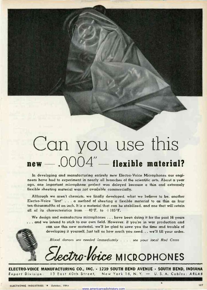
Can you use this new .0004 flexible material?
In developing and manufacturing entirely new Electro -Voice Microphones our engi- neers have had to experiment in nearly all branches of the scientific arts. About a year ago, one important microphone project was delayed because a thin and extremely flexible sheeting material was not available commercially.
Although we aren't chemists, we finally developed, what we believe to be, another Electro -Voice "first"' . . . a method of sheeting a flexible material to as thin as four ten -thousandths of an inch. It is a material that can be stabilized, and one that will retain all of its characteristics from -40°F. to + 185°F.
We design and manufacture microphones .. . have been doing it for the past 16 years . and we intend to stick to our own field. However, if you're in war production and
can use this new material, we'll be glad to save you the time and trouble of developing it yourself. Just tell us how much you need... we'll fill your order.
Blood donors are needed immediately . . . . see your local Red Cross
-Kee MICROPHONES ELECTRO -VOICE MANUFACTURING CO., INC. 1239 SOUTH BEND AVENUE SOUTH BEND, INDIANA Export Division: 13 East 40th Street, New York 16, N. Y. - U. 5. A. Cables: ARLAB
ELECTRONIC INDUSTRIES October, 194{ 187
www.americanradiohistory.com
Ì i-'e » FOR e It difficult
to r N E nverter secureV Rat w`nn;r s'ine new Ge
Yoar p'esthe v er is devoting Sets N I sed you.- 9;omeñ
ut we 9 all outs resources new Roter os, SerzS vioe fon. r td
will, helprces tOward °"f.f,SE Department.
6Y letter, to Pioneer'syou
keep e 'On
188
rO,Oqf Pp
eers wfº PLANTS
Cf"
BAKELITE FABRICATION BASED ON EXPERIENCE There are no handbooks in the fabricating business. Only years of experience can give that added touch-sharpening a cut- ter-designing a tool-for the type of work you expect. All parts that can be fabricated from lami- nated sheets, rods, or tubes, are available. Twenty years of experience at your service. Write us, or phone us, and we will have an engineer call on you for consultation.
ELECTRICAL INSULATION CO., INC. 12 VESTRY STREET, NEW YORK CITY
Sheets, Rods, and Tubes - Fabricated Parts
BROAD -BAND AMPLIFIERS
(Continued from page 94)
Grateful acknowledgement is made to Dr. Hans Salinger, Con- sultant, Farnsworth Television & Radio Corporation, for development of the SN integration reduction.
Appendix The general integral, SN of equa-
tion (40) can be solved as follows5:
(,2 1
)(4N-1) (1) SN = + s2/ IN
Where (2) IN
dz
° (1-2z2 cos 2 O + z4)N
The integral IN is computed from:
(3) I IÑ -1+ 1 u 1 dIN-1
-1 2 4u/ du
1 1 d (N-2) u du
(4) Where u
= Sin O= p (3) may be reduced by the use
of auxiliary formulae for N = 2 and N = 1:
dIN-2)
u du
2
(5) I2 = I3 + (u - 1 dIl 2 8u du
(6) It = 142 + s2 /4p 4. J. R. Nelson, "Proceedings of
the I.R.E., July, 1932.
DESIGNING AF FILTERS (Continued from page 73)
duced to a positive or negative re- actance in series or in parallel with R,.
The insertion loss due to a react- ance in series with input and out- put resistances R. and Re expressed in decibels is: «g2 = 20 log [1 + ]1 db or (R. +R.)2 cc = 10 log [1 + X2 ] db (a)
(R, + R0)2. The insertion loss in decibels due
to a reactance in parallel with R. is equal to:
[ R, R. ] 4
cc = 20 log 1 + (R, +R0)x or
« = 10 log [1 C(R'
R. , -f- R.)2 x2] (b)
In many applications such as operating into a grid of a vac- uum tube, R' R. is indetermi-
R, + R. ELECTRONIC INDUSTRIES October, 1943
www.americanradiohistory.com
THESE FIRMS', USE
lee% evrepoe4:54- fee
GOATserves a.mcst every electronic tube manufacturer with a tremen-
de. s variety of st2C aid special parts, made of any metal to an f specified degree
of accuracy. Becaus of experience gained since the days of radio infancy, GOAT
has been able to meet the demands of this industry for greater duality, durability anc quartity production. GOAT'S prestige, today, is based c n this consistent ability to -andle tough Lobs requir ng skill, precision and efficiency.
SrAMPUIG C{OUNES For Small Torch ,ob.:
ELE;THIC PRODUCTS IBC.
T 1 PI C AL PARTS SFowl hare are just a few EJaT elect,onc tube parts and .fields that Cabe seen stamped, d-axn and tornad on GOAT macFires, dies ana presses.
METAL STAMP N S INC. A DIVISION OF THE FRED GOAT CO., INC...EST. 1893
314 DEAN STREET BROOKLYN, N. Y.
ELECTRONIC IINDJST.IES October. 1941 189
www.americanradiohistory.com
New and Old Workers find SPINTITE the fastest wrench for speedy assembly of small parts. Standard sizes with hex sockets from 3/16" to 5/8". Knurled Round and Square Sockets available on special order. SPINTITE works like a screw driver
T 51 Set in Leatherette
Roll includes 7 SPINTITES
3 screw drivers and chuck type
handle
1.1 tIEliÌ :l , 1I1llliln
STEVENS WALDEN, INC. 462 SHREWSBURY STREET
WORCESTER, MASSACHUSETTS, U. S. A.
BACK THE ATTACK !
BUY WAIl BONDS
190
nate as it reduces to cc . Divid- co
ing the numerator and the denom- inator by R., this expression is re- duced to R' When R. = co, R,+1.
R. this expression becomes equal to R, and the equation (b) becomes
cc =10 log [i+(X )2] db.
The insertion loss at any fre- quency, outside the resonant fre- quency, may be determined either mathematically from equations (a) and (b) or from the alignment charts in Figs. 5 and 6. The use of the alignment charts reduces considerably the time necessary for calculations so that several points on the performance curve may be rapidly determined.
Neither the equation (a) or (b), nor the alignment charts take into consideration the effect of dissipa- tion in the reactors or condensers. This effect is pronounced near res- onance only and is of little im- portance in the case of the band rejection circuits of Figs. 3 and 4. In the case of band-pass circuits of Fig. 1 and Fig. 2 it may be as- sumed that the total attenuation near the resonant frequency equals roughly the attenuation obtained from the alignment charts plus the insertion loss at the resonant fre- quency.
At the resonant frequency the LC circuit becomes, for all practical purposes, resistive in either the series or parallel combination; the resistance of the series circuit is
XQl" , while that of the parallel cir-
cuit is equal to QXL. The dissipa- tion in the capacitor can usually be neglected, so that the Q of the coils only, enters into the calcula- tions. The expression for insertion loss at resonance is given in Figs. 1 to 4.
Examples To design a resonant circuit to
pass a signal of a 1000 cps., with the second harmonic (or 2000 cps.) attenuated 30 db, assume the cir- cuit is to work between R, = 500 ohms and R. = 1000 ohms, and that coils with a Q of 40 are avail- able. Either circuits Fig. 1 or Fig. 2 may be used to obtain the band- pass effect. Trying the circuit shown in Fig. 1, from equation (a) or from the alignment chart in Fig. 5, it is found that X1 = 4700 ohms. From the relation X1 =
XL(N' - 1
N ), and N = 2, we find that
XL = 31200 ohms. A coil having an inductance of 5 henries used with a capacitance of 0.0051 microfarads resonates at a 1000 cps. The inser- tion loss at the resonant frequency ELECTRONIC INDUSTRIES October, 1943
www.americanradiohistory.com
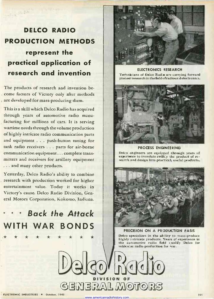
DELCO RADIO
PRODUCTION METHODS
represent the practical application of research and invention
The products of research and invention be- come factors of Victory only after methods are developed for mass-producing them.
This is a skill which Delco Radio has acquired through years of automotive radio manu- facturing for millions of cars. It is serving wartime needs through the volume production of highly intricate radio communication parts and equipment . . . push-button tuning for tank radio receivers ... parts for air -borne communication equipment ... complete trans- mitters and receivers for artillery equipment ... and many other products.
Yesterday, Delco Radio's ability to combine research with production worked for higher entertainment value. Today it works in Victory's cause. Delco Radio Division, Gen- eral Motors Corporation, Kokomo, Indiana.
Back the Attack WITH WAR BONDS * * * * * * * * *
ELECTRONICS 2ESEARCH
Te hniicians of Delco Rad_ are carrying forward piar.ee- research in the field cfrad ioar_d elects onics.
PROCESS ENG1NEER1NG
Delco engineers are equipped through years of experience to translate ewifit_y the product of re- search and design into practical, useful products.
PRECtSION ON A PRODUCTION OASIS
Delco specializes in the atiliry to -Hass-produce highly i-rtricate products. Years of experience in the aJtomotive radio field cua1i y Delco for vehicu ar radio production for war.
ELECTRONIC INDUSTRIES October, 1943
DIVISION OF
1[2,b ,3ú 191
www.americanradiohistory.com
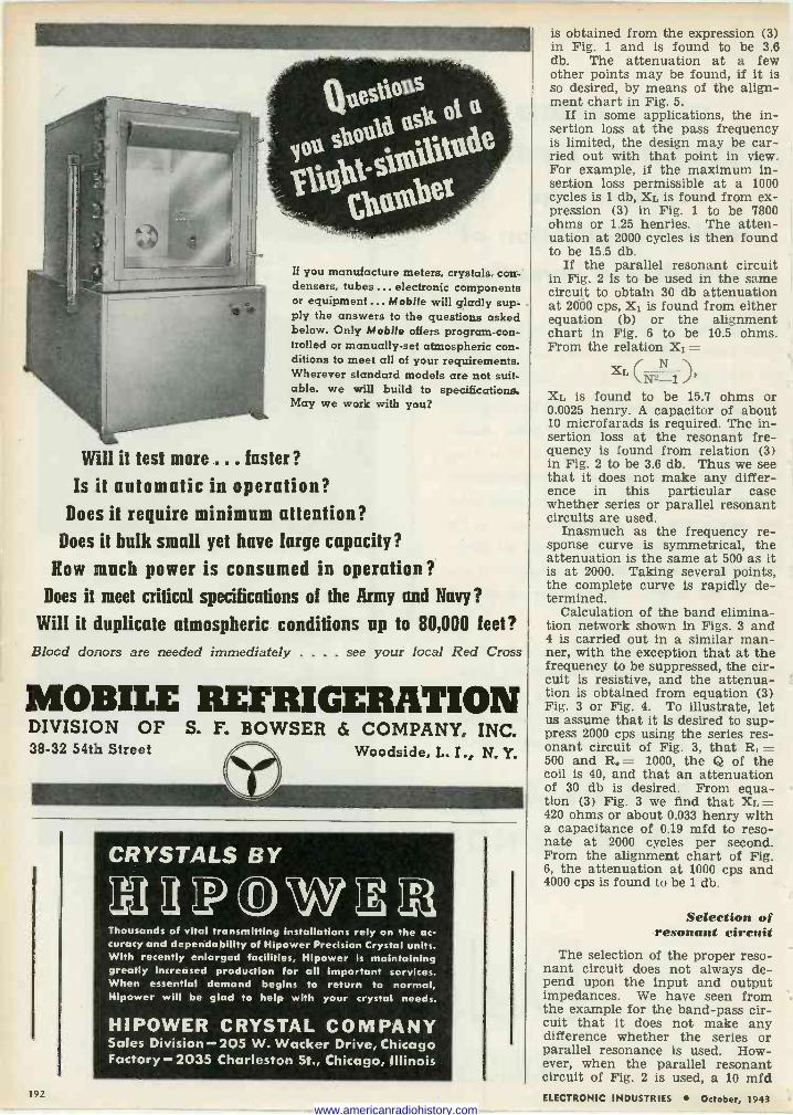
If you manufacture meters, crystals, con- densers, tubes.., electronic components or equipment... Mobile will gladly sup- -
ply the answers to the questions asked below. Only Mobile offers program -con- trolled or manually -set atmospheric con- ditions to meet all of your requirements. Wherever standard models are not suit- able, we will build to specifications. May we work with you?
Will it test more ... faster? Is it automatic in operation?
Does it require minimum attention? Does it bulk small yet have large capacity?
Now much power is consumed in operation? Does it meet critical specifications of the Army and Navy?
Will it duplicate atmospheric conditions up to 80,000 feet? Blood donors are needed immediately . . . . see your local Red Cross
MOBILE REFRIGERATION DIVISION OF S. F. BOWSER & COMPANY, INC. 38-32 54th Street Woodside, L. I., N. Y.
CRYSTALS BY
121LP W",211 Thousands of vital transmitting installations rely on the ac- curacy and dependability of Hipower Precision Crystal units. With recently enlarged facilities, Hipower is maintaining greatly Increased production for all Important services. When essential demand begins to return to normal, Hipower will be glad to help with your crystal needs.
HIPOWER CRYSTAL COMPANY Sales Division - 205 W. Wacker Drive, Chicago Factory -2035 Charleston St., Chicago, Illinois
192
is obtained from the expression (3) in Fig. 1 and is found to be 3.6 db. The attenuation at a few other points may be found, if it is so desired, by means of the align- ment chart in Fig. 5.
If in some applications, the in- sertion loss at the pass frequency is limited, the design may be car- ried out with that point in view. For example, if the maximum in- sertion loss permissible at a 1000 cycles is 1 db, XL is found from ex- pression (3) in Fig. 1 to be 7800 ohms or 1.25 henries. The atten- uation at 2000 cycles is then found to be 15.5 db.
If the parallel resonant circuit in Fig. 2 is to be used in the same circuit to obtain 30 db attenuation at 2000 cps, X1 is found from either equation (b) or the alignment chart in Fig. 6 to be 10.5 ohms. From the relation X1 =
XL N
2 N-1 ' XL is found to be 15.7 ohms or 0.0025 henry. A capacitor of about 10 microfarads is required. The in- sertion loss at the resonant fre- quency is found from relation (3) in Fig. 2 to be 3.6 db. Thus we see that it does not make any differ- ence in this particular case whether series or parallel resonant circuits are used.
Inasmuch as the frequency re- sponse curve is symmetrical, the attenuation is the same at 500 as it is at 2000. Taking several points, the complete curve is rapidly de- termined.
Calculation of the band elimina- tion network shown in Figs. 3 and 4 is carried out in a similar man- ner, with the exception that at the frequency to be suppressed, the cir- cuit is resistive, and the attenua- tion is obtained from equation (3) Fig. 3 or Fig. 4. To illustrate, let us assume that it is desired to sup- press 2000 cps using the series res- onant circuit of Fig. 3, that R, = 500 and R. = 1000, the Q of the coil is 40, and that an attenuation of 30 db is desired. From equa- tion (3) Fig. 3 we find that XL = 420 ohms or about 0.033 henry with a capacitance of 0.19 mfd to reso- nate at 2000 cycles per second. From the alignment chart of Fig. 6, the attenuation at 1000 cps and 4000 cps is found to be 1 db.
Selection of resonant circuit
The selection of the proper reso- nant circuit does not always de- pend upon the input and output impedances. We have seen from the example for the band-pass cir- cuit that it does not make any difference whether the series or parallel resonance is used. How- ever, when the parallel resonant circuit of Fig. 2 is used, a 10 mfd ELECTRONIC INDUSTRIES October, 1943
www.americanradiohistory.com
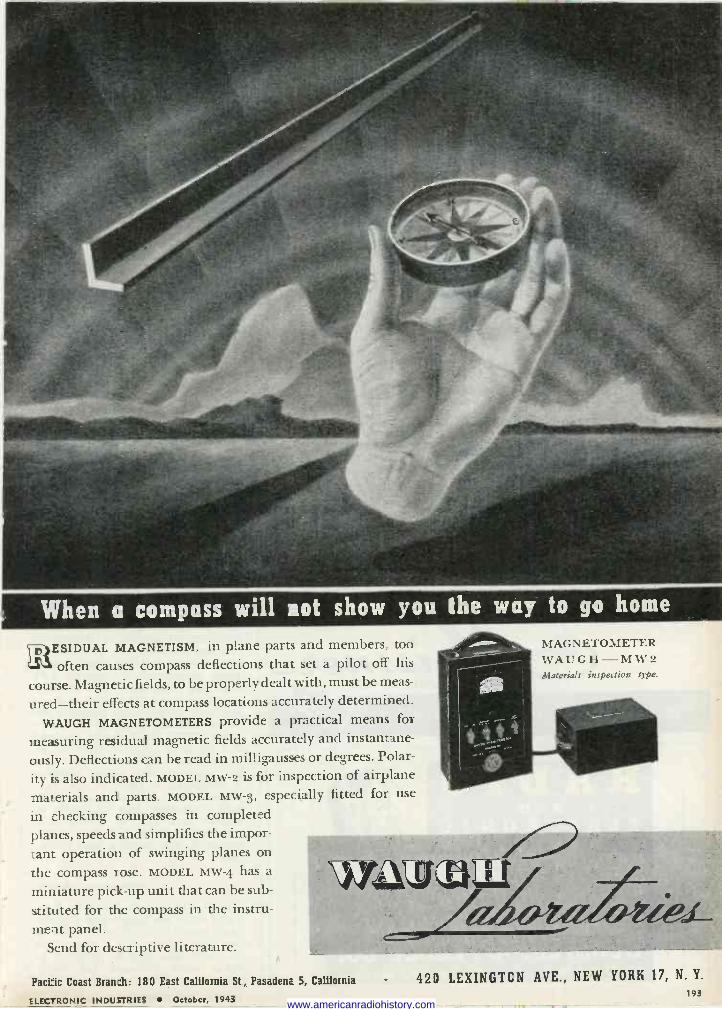
When a compass will not show you the way to go home
p SIDUAL MAGNETISM, in plane parts and members, too
often causes compass deflections that set a pilot off his
course. Magnetic fields, to be properly dealt with, must be meas-
ured-their effects at compass locations accurately determined.
WAUGH MAGNETOMETERS provide a practical means for
measuring residual magnetic fields accurately and instantane-
ously. Deflections can be read in milligausses or degrees. Polar -
it} is also indicated. MODEL MW -2 is for inspection of airplane
materials and parts. MODEL MW -3, especially fitted for use
in checking compasses in completed planes, speeds and simplifies the impor-
tant operation of swinging planes on the compass rose. MODEL MW -4 has a
miniature pick-up unit that can be sub-
stituted for the compass in the instru- ment panel.
Send for descriptive literature.
WMMULt
MAGNETOMETER WAUGH-MW2 Materials inspection type.
Pacific Coast Branch: 180 East California St., Pasadena 5, California
ELECTRONIC INDUSTRIES October, 1943
420 LEXINGTON AVE., NEW YORK 17, N. Y.
193 www.americanradiohistory.com
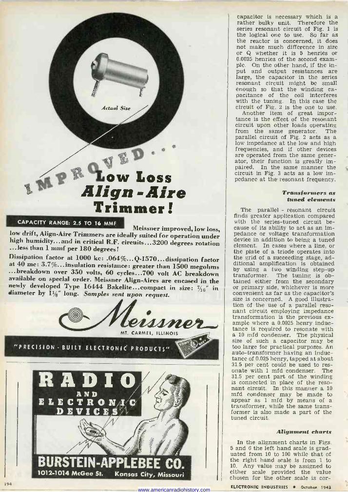
,. (01 la
ow Loss liege asilign -Aire
Trimmer CAPACITY RANGE: 2.5 TO 16 MMF
Meissner improved, low loss, low drift, Align -Aire Trimmers are ideally suited for operation under high humidity...and in critical R.F. circuits...3200 degrees rotation ...less than 1 mmf per 180 degrees! Dissipation factor at 1000 kc: .064%... Q-1570... dissipation factor at 40 mc: 3.7%...insulation resistance: greater than 1500 megohms ...breakdown over 350 volts, 60 cycles...700 volt AC breakdown available on special order. Meissner Align -Aires are encased in the newly developed Type 16444 Bakelite...compact in size: 16" in diameter by 1i/8" long. Samples sent upon request.
I MT. CARMEL, ILLINOIS
"PRECISION - BUILT ELECTRONIC PRODUCTS"
BURSTEIN-APPLEBEE CO. 1012-1014 McGee St. Kansas City, Missouri
capacitor is necessary which is a rather bulky unit. Therefore the series resonant circuit of Fig. 1 is the logical one to use. So far as the reactor is concerned, it does not make much difference in size or Q whether it is 5 henries or 0.0025 henries of the second exam- ple. On the other hand, if the in- put and output resistances are large, the capacitor in the series resonant circuit might be small enough so that the winding ca- pacitance of the coil interferes with the tuning. In this case the circuit of Fig. 2 is the one to use.
Another item of great impor- tance is the effect of the resonant circuit upon other loads operating from the same generator. The parallel circuit of Fig. 2 acts as a low impedance at the low and high frequencies, and if other devices are operated from the same gener- ator, their function is greatly im- paired. In the same manner the circuit in Fig. 3 acts as a low im- pedance at the resonant frequency.
Transformers as tuned elements
The parallel - resonant circuit finds greater application compared with the series -tuned circuit be- cause of its ability to act as an im- pedance or voltage transformation device in addition to being a tuned element. In cases where a line, or the plate of a triode operates into the grid of a succeeding stage, ad- ditional amplification is obtained by using a two winding step-up transformer. The tuning is ob- tained either from the secondary or primary side, whichever is more convenient as far as the capacitor's size is concerned. A good illustra- tion of the use of a parallel reso- nant circuit employing impedance transformation is the previous ex- ample where a 0.0025 henry induc- tance is required to resonate with a 10 mfd condenser. The physical size of such a capacitor may be too large for practical purposes. An auto -transformer having an induc- tance of 0.025 henry, tapped at about 31.5 per cent could be used to res- onate with 1 mfd condenser. The 31.5 per cent part of the winding is connected in place of the reso- nant circuit. In this manner a 10 mfd condenser may be made to appear as 1 mfd by means of a transformer, while the same trans- former is also made a part of the tuned circuit.
Alignment charts In the alignment charts in Figs.
5 and 6 the left hand scale is grad- uated from 10 to 100 while that of the right hand scale is from 1 to 10. Any value may be assigned to either scale provided the value chosen for the other scale is cor -
194 ELECTRONIC INDUSTRIES October, 1943 www.americanradiohistory.com
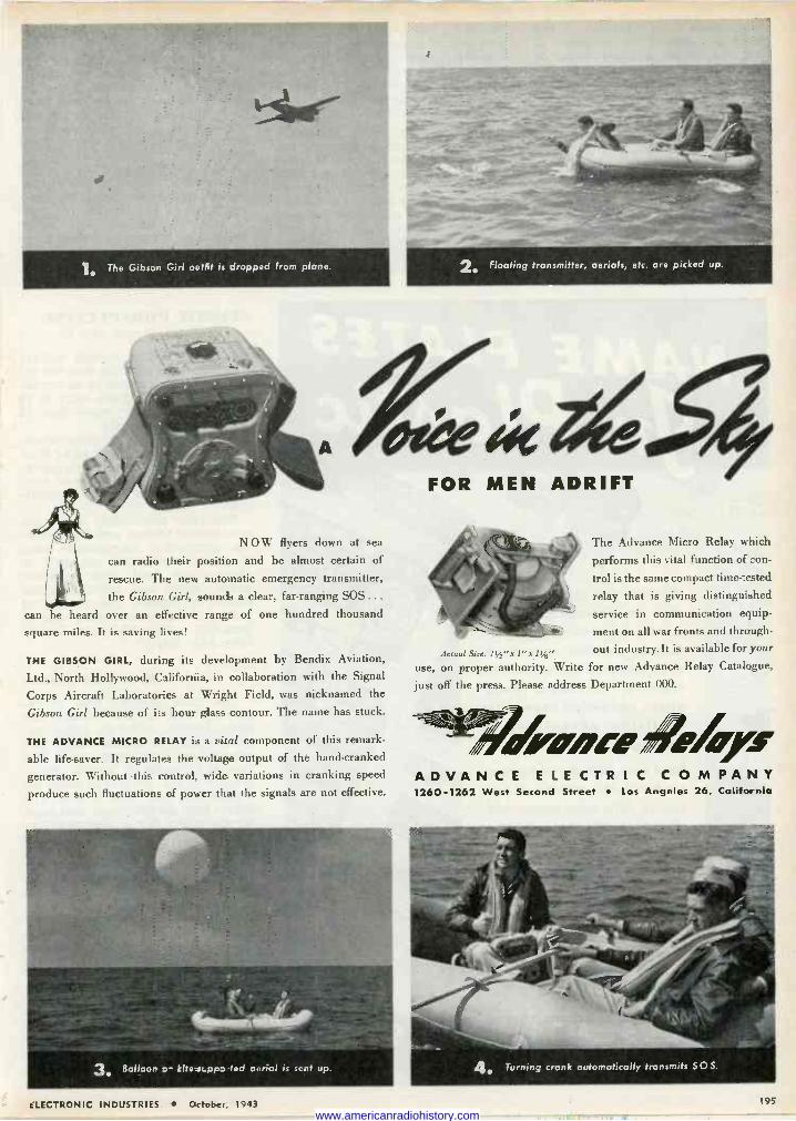
Ì The Gibson Girl outfit is dropped from plane.
N O W flyers down at sea
can radio their position and be almost certain of
rescue. The new automatic emergency transmitter,
the Gibson Girl, sounds a clear, far-ranging SOS ... can be heard over an effective range of one hundred thousand
square miles. It is saving lives!
THE GIBSON GIRL, during its development by Bendix Aviation,
Ltd., North Hollywood, California, in collaboration with the Signal
Corps Aircraft Laboratories at Wright Field, was nicknamed the
Gibson Girl because of its hour glass contour. The name has stuck.
THE ADVANCE MICRO RELAY is a vital component of this remark-
able life-saver. It regulates the voltage output of the hand -cranked
generator. Without -this control, wide variations in cranking speed
produce such fluctuations of power that the signals are not effective.
3 Balloon kite st.apo-ted aerial is sent up.
2 Floating transmitter, aerials, etc. are picked up.
FOR MEN ADRIFT
The Advance Micro Relay which
performs this vital function of con-
trol is the same compact time -tested
relay that is giving distinguished
service in communication equip-
ment on all war fronts and through -
Actual Sae: 1 t/2"x 1"x 1'/s out industry.It is available for your
use, on proper authority. Write for new Advance Relay Catalogue,
just off the press. Please address Department 000.
orcee%s ADVANCE E LE CTR I C COMPANY 1260-1262 West Second Street Los Angeles 26, California
4 Turning crank automatically transmits SOS.
ELECTRONIC INDUSTRIES October 1943 195
www.americanradiohistory.com
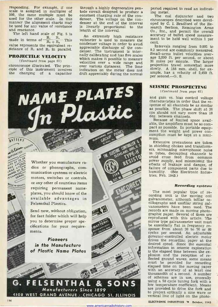
responding. For example, if one scale is assigned in multiples of 100, the same multiple must be used for the other scale. In this manner the alignment charts may be used for any value of resistance and reactance.
The left hand scale of Fig. 5 is
made in terms of R, R°
This R, + R. value represents the equivalent re- sistance of R. and R. in parallel.
PROJECTILE VELOCITY (Continued from page 67)
chronoscope illustrated. The prin- ciple of this instrument involves the charging of a capacitor
through a highly degenerative pen- tode circuit designed to produce a constant charging rate of the con- denser. The voltage on the con- denser at the end of the interval is linearly proportional to the length of the interval.
An extremely high resistance voltmeter is used to measure the condenser voltage in order to avoid appreciable discharge of the con- denser. The instrument is inter- nally calibrating and has five scales which makes it possible to measure velocities over a wide range and over various distances. The time indication on the meter does not drift appreciably during the normal
..,
Whether you manufacture ra- dios or phonographs, com- munication systems or electric motors, switches or controls, or any other of countless items requiring permanent name- plates, you should know of the available advantages in Felsenthal Plastics.
Send now, without obligation, for fact folder which will help you to determine proper spe- cifications for your require- ments.
Pioneers in the Manufacture
of Plastic Name Plates
G. FELSENTHAL & SONS Manufacturers Since 1899
4108 WEST GRAND AVENUE CHICAGO 51, ILLINOIS 196
period required to read an indicat- ing meter.
The coil disjunctor and two chronoscopes described were devel- oped by C. I. Bradford of the Re- search Section, Remington Arms Co., Inc., and permit the overall accuracy of bullet speed measure- ment to be held well within 1 per cent.
Intervals ranging from 0.001 to 0.2 second are commonly measured. Small -arms bullet velocities aver- age 2,800 ft. per second, or about 31 miles per minute. The larger projectiles travel somewhat more slowly. A 155 mm. shell, for ex- ample, has a velocity of 2,450 ft. per second.-G. S.
SEISMIC PROSPECTING (Continued froin page 65)
and gain vs. bias control voltage characteristics in order that the re- sponse of all channels be as similar as possible. The phase shift at 20 cps should not vary more than 10 deg. between channels.
Because of limited space avail- able, the amplifiers must be as com- pact as possible. In portable equip- ment the weight and power con- sumption must be kept at a mini- mum.
Extensive precautions are taken in shielding chokes and transform- ers, minimizing microphonic noise in tubes, decoupling channels to avoid cross feed from common power supply, and minimizing the effects of leakage and danger, of failure of component parts due to humidity. (See Electronic Indus- tries, Feb. 1943.)
Recording systems The most popular type of re-
cording unit is the moving coil galvanometer, although bifilar os- cillographs and unifilar string gal- vanometers have been used. The records are made on moving photo- graphic paper. Several of them are reproduced with this article. The mirror type galvanometer unit must be essentially flat in frequency re- sponse from about 20 to 70 or 80 cycles per second. An adjustable governor -controlled electric motor drives the recording paper at the desired speed. Since the essential information in seismic exploration is the elapsed time between the ex- plosion and the reception of re- flected ground waves, some means must be provided for recording elapsed time on the moving paper with an accuracy of at least one thousandth of a second. A number of schemes are in use, generally using a 50 cycle tuning fork with a low temperature coefficient. Means are provided to drive the fork and to project optically a sine wave or vertical line of light on the photo - ELECTRONIC INDUSTRIES October, 1943
www.americanradiohistory.com
To the hams to the engineers to the technicians still in mufti to the old hands at the new games of war
To all the valiant brothers and sisters fashioning victory in the labs and assembly lines
Ken -Rad dedicates its complete effort to war for an early Peace
KE N -RAD TRANSMITTING TUBES CATHODE RAY TUBES
INCANDESCENT LAMPS SPECIAL PURPOSE TUBES
FLUORESCENT LAMPS METAL AND VHF TUBES
OWENSBORO KENTUCKY U S A ELECTRONIC INDUSTRIES Octobe,, 1943 197
www.americanradiohistory.com
graphic paper at each half cycle of the fork swing.
A number of methods have been used to detect and record the in- stant of the explosive charge's de- tonation. This may be done by making or breaking an electrical contact at the site of the explo- sion, by detection of the sound waves, or by placing one geophone unit beside the shot -hole.
Power supply for the entire ex- ploration unit is obtained from a storage battery or from a combi- nation of A and B batteries. Plate supply may be obtained from a vibro -pack, motor generator, or from B batteries. Equipment is
usually designed for minimum power consumption in the field.
Sound -on -film recording An interesting variation in re-
cording technique is the use of the Rieber "Sonograph," an instrument which records the returning wave energy as a series of variable area or variable -density sound -tracks on 35 mm. film. The film is then run through an analyzer unit which translates the tracks into the con- ventional wave traces on photo- graphic paper. By reading the waves from each geophone in phonographically reproducible
N thousands of varied shapes "fighting wire" is on and
' the war fronts. In bombé and
nd shell ma;
in tanks terial of
guns and planes; in equip nags doing
types, you'll find wireforms and sp
a thousand -and -one vital job
you see a few of the many Accurate -made
Above, parts of fighting irn-
sp which are'huge quantities s t- o
plemalwire shapesproduced rigid control
Accurate
They'reunder rig products.
Accurate precision standards inspected finished
from ra on
WHAT
SPECIAL
WIREFORMS
DO YOU
NEED?
v. materials to experience and
Accurate "know-how", based production
can help you solve yourTell us probspecialization, springsolve
and wireforms.
whatyou tnee'"and
when you need it-it's as simple
what need
as that. Free "Handbook on Springs". Send for your copy today. It is infor- mative, compact, handy
to use.
ACCURATE SPRING MFG. CO., 3303 W. Lake St., Chicago, III.
form, re -running this series of rec- ords is equivalent to repeating the shot, except that the circuit condi- tion may be varied for each repeti- tion.
By adding the reproduced waves algebraically, a directional sensi- tivity is conferred on the over-all performance. The axis of maxi- mum sensitivity may be changed by varying the relative times of re- production from the individual rec- ords before combining. Thus, the playback may be made responsive to waves from any desired direc- tion, and insensitive to waves from other directions.
Faulted geological structures, un - conformities and other complexi- ties give rise to returned waves, often arriving from many direc- tions at the same time. Recorded on the ordinary multi -trace oscillo - graphic records, such wave -mix- tures are so confused as to defy visual analysis. The sonograph can readily separate such complex pat- terns, thus opening for explanation considerable areas which may pos- sibly be productive, but which can- not be explained by conventional means.
Prospecting methods
Two general types of ground waves can be detected near an ex- ploded dynamite charge. First to arrive at the receiving point are the refracted waves, which pene- trate to the first layer or medium of low impedance, travel rapidly through it, and are then trans- mitted back to the surface to actu- ate the geophones.
The earliest method of seismic exploration made use of this phe- nomenon exclusively. The receiv- ers were placed at some distance, perhaps up to five miles, from the shot -point, which consisted of a rather heavy charge up to 10 tons. Reception of several refracted waves at different intervals gave clues to the existence of media of higher than average velocity be- tween the shot -point and the re- ceiver. A number of receivers were frequently placed in a circle sur- rounding the shot -point in what was known as "fan shooting." A salt dome, one of the most common oil structures in the Gulf region, between the shot -point and any geophone on the circle would re- sult in reception of the first wave at that point considerably ahead of the reception by the other pick- ups. Simultaneous starting of all receivers was frequently done by radio control from the shot -point.
Refraction shooting has been al- most replaced by reflection shoot- ing, the method in which a portion of the energy from the descending pressure wave is reflected back to the surface by each layer of dif- ELECTRONIC INDUSTRIES October, 1943
www.americanradiohistory.com
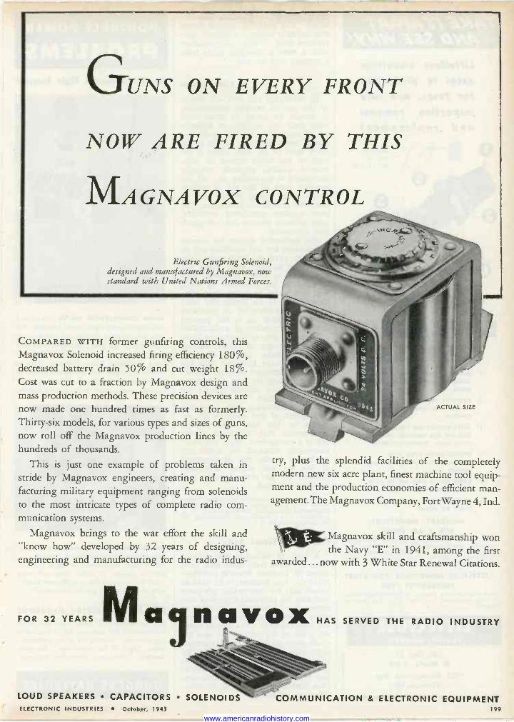
GUNS ON EVERY FRONT
NOW ARE FIRED BY THIS
MAGNAVOX CONTROL
Electric Gunfiring Solenoid, designed and manufactured by Magnavox, now standard with United Nations Armed Forces.
COMPARED WITH former gunfiring controls, this Magnavox Solenoid increased firing efficiency 180%, decreased battery drain 50% and cut weight 18%. Cost was cut to a fraction by Magnavox design and mass production methods. These precision devices are now made one hundred times as fast as formerly. Thirty-six models, for various types and sizes of guns, now roll off the Magnavox production lines by the hundreds of thousands.
This is just one example of problems taken in stride by Magnavox engineers, creating and manu- facturing military equipment ranging from solenoids to the most intricate types of complete radio com- munication systems.
Magnavox brings to the war effort the skill and "know how" developed by 32 years of designing, engineering and manufacturing for the radio indus -
FOR 32 YEARS
ACTUAL SIZE
try, plus the splendid facilities of the completely modern new six acre plant, finest machine tool equip- ment and the production economies of efficient man- agement. The Magnavox Company, Fort Wayne 4, Ind.
Magnavox skill and craftsmanship won the Navy "E" in 1941, among the first
awarded... now with 3 White Star Renewal Citations.
Mciuñavox HAS SERVED THE RADIO INDUSTRY
LOUD SPEAKERS CAPACITORS SOLENOIDS COMMUNICATION & ELECTRONIC EQUIPMENT ELECTRONIC INDUSTRIES October, 1943 199
www.americanradiohistory.com
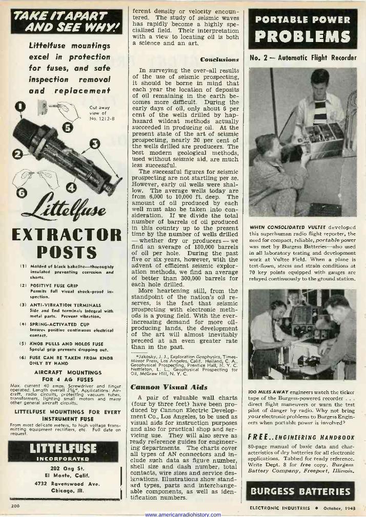
TARE /7" APART AND SEE WM/Y.'
Littelfuse mountings excel in protection for fuses, and safe inspection removal and replacement
Cut away view of No. 1212-B
itte«ae EXTRACTOR
POSTS (1) Molded of black bakelite-thoroughly
insulated pr ting corrosion and shorts.
(2) POSITIVE FUSE GRIP Permits full visual shock -proof in- spection.
(3) ANTI -VIBRATION TERMINALS Side and End terminals integral with metal parts. Prevent vibration.
(4) SPRING -ACTIVATED CUP Insures positive continuous electrical contact.
(5) KNOB PULLS AND HOLDS FUSE Special grip prevents dropping out.
(6) FUSE CAN BE TAKEN FROM KNOB ONLY BY HAND
AIRCRAFT MOUNTINGS FOR 4 AG FUSES
Max. current 40 amps. Screwdriver and finger operated. Length overall 25/8". Applications: Air- craft, radio circuits, protecting vacuum tubes, transformers, lighting small motors and many other general aircraft circuits.
LITTELFUSE MOUNTINGS FOR EVERY INSTRUMENT FUSE
From most delicate meters, to high voltage trans- mitting equipment rectifiers, etc. Full date on request.
LITTELFUSE INCORPORATED
202 Ong St. El Monte, Calif.
4732 Ravenswood Ave. Chicago. Ill.
ferent density or velocity encoun- tered. The study of seismic waves has rapidly become a highly spe- cialized field. Their interpretation with a view to locating oil is both a science and an art.
Conclusions
In surveying the over-all results of the use of seismic prospecting, it should be borne in mind that each year the location of deposits of oil remaining in the earth be- comes more difficult. During the early days of oil, only about 6 per cent of the wells drilled by hap- hazard wildcat methods actually succeeded in producing oil. At the present state of the art of seismic prospecting, nearly 20 per cent of the wells drilled are producers. The best modern geological methods, used without seismic aid, are much less successful.
The successful figures for seismic prospecting are not startling per se. However, early oil wells were shal- low. The average wells today are from 6,000 to 10,000 ft. deep. The amount of oil produced by each well must also be taken into con- sideration. If we divide the total number of barrels of oil produced in this country up to the present time by the number of wells drilled - whether dry or producers - we find an average of 180,000 barrels of oil per hole. During the past five or six years, however, with the advent of efficient seismic explor- ation methods, we find an average of better than 300,000 barrels for each hole drilled.
More heartening still, from the standpoint of the nation's oil re- serves, is the fact that seismic prospecting with electronic meth- ods is a young field. With the ever- increasing demand for more oil - producing lands, the development of the art will almost inevitably preceed at an even greater rate than in the past.
*Jakosky, J. J., Exploration Geophysics, Times- Mirror Press, Los Angeles, Calif. Heiland, C. A., Geophysical Prospecting, Prentice Hall, N. Y. C. Nettleton, L. L., Geophysical Prospecting for Oil, McGraw Hill, N. Y. C.
Cannon Visual Aids A pair of valuable wall charts
(four by three feet) have been pro- duced by Cannon Electric Develop- ment Co., Los Angeles, to be used as visual aids for instruction purposes and also for practical shop and ser- vicing use. They will also serve as ready reference guides for engineer- ing departments. The charts cover all types of AN connectors and in- clude such data as figure number, shell size and dash number, total contacts, wire sizes and service des- ignations. Illustrations show stand- ard types, parts and interchange- able components, as well as iden- tification numbers.
PORTABLE POWER
PROBLEMS No. 2 - Automatic Flight Recorder
WHEN CONSOLIDATED VULTEE developed this superhuman radio flight reporter, the need for compact, reliable, portable power was met by Burgess Batteries-also used in all laboratory testing and development work at Vultee Field. When a plane is test -flown, stress and strain conditions at 70 key points equipped with gauges are relayed continuously to the ground station.
100 MILES AWAY engineers watch the ticker tape of the Burgess -powered recorder .. .
direct flight maneuvers or warn the test pilot of danger by radio. Why not bring your electronic problems to Burgess Engin- eers when portable power is involved?
FREE.. ENGINEERING HANDBOOK
80 -page manual of basic data and char- acteristics of dry batteries for all electronic applications. Tabbed for ready reference. Write Dept. 8 for free copy. Burgess Battery Company, Freeport, Illinois.
BURGESS BATTERIES 200 ELECTRONIC INDUSTRIES October, 1943
www.americanradiohistory.com
They Won't Forget "Rola" R' IGHT now manufacturers of war materials can
be making friends for tomorrow's products, products that do not yet exist ... that may not even have reached the blueprint stage. For if what a Com- pany makes for. War gives good account of itself, isn't there likely to be a greater confidence in the Company's peacetime products?
Take Rola for example. In leading factories through- out the country skilled mechanics are building thou- sands of communications systems for the Army -Navy Air Forces ... using various important parts made by
Rola. In countless places all over the world techni- cally trained military personnel are installing and maintaining these systems, again with Rola equipment.
When their wartime job is done, most of these men will continue in their chosen field and will occupy positions of importance and influence in all' branches
3
of Radio and Electronics. We firmly believe that into their peacetime jobs these same men will carry the highest regard for everything that bears the name "Rola", a regard born of the first-hand knowledge that a Rola product ... whatever it may be ... is a
Quality product.
At least we can think of no way to make more cer- tain "they won't forget Rola", than to continue to provide the very best equipment it is possible to make. THE ROLA COMPANY, Inc., 2530 Superior Avenue, Cleveland 14, Ohio.
e s s
New applications constantly are being found for Rola's diver- sified equipment and broad manufacturing experience. If your production problems involve anything related to our field. we believe you should see what Rola has to offer,
ROLA MAKERS OF THE FINEST IN SOUND REPRODUCING AND ELECTRONIC EQUIPMENT ELECTRONIC INDUSTRIES October, 1943 201
www.americanradiohistory.com
PRECISION PARTS
BOLTS FOR DRIVING THE ENEMY NUTS
An airplane depends on this.
These fine precision -machined pieces ride the skies all over the world. They are on15 a small part of Uncle Sam's swift -moving ships of the air-but a vital part. They are machined at Ace from rough forgings to highly accurate finished pieces. The grinding of the threads, as well as the turning and grinding of the various diameters, must be held to exceptionally close tolerances . . . and, if you look closely, you'll see an .060" diameter hole drilled through the thickness of the head.
The ability to do highly accurate machining and grinding ... and to do it on a mass production basis . . . is an accomplishment this war has taught us. Today, when you need small parts or assemblies come to Ace, and we will try to fit them in with our present production. Here you'll find not only the modern precision machinery, but the skill, the background, and the ingenuity to use those machines to get the required results.
The Ace story on precision work will interest you. Send jor a copy.
ACE MANUFACTURING CORPORATION for Precision Parts
1239 E. ERIE AVE., PHILADELPHIA 24, PA 202
And Now the "Radar Corp. of America"
The Radar Corp. of America was recently organized by the Klein- man Doroshaw Ackerman group of the American Industries Manage- ment Co., 11 South LaSalle St., Chicago (3), Ill., for the purpose of acquiring several sizeable operating units. Its officers and directors are as follows: J. M. Doroshaw, presi- dent; J. S. Ackerman, vice-presi- dent; Emanuel Goldstrich, secre- tary -treasurer, and E. I. Kleiman, director.
Other associated companies are Investment Corp. of North Amer- ica, Schwarze Electric Co., Stanley & Patterson, Inc., Victory Products & Mfg. Corp., and Marquette Food Industries.
Van Norman Machine Tool in Induction Heating
Van Norman Machine Tool Co., Springfield, Mass., which since its inception in 1912 has been an im- portant producer of machine tools and particularly of automotive ser- vice equipment, has recently taken up the production of induction heating equipment. As a means to- ward indicating the enlarged scope of its operations, the name of the company has been abbreviated to Van Norman Co.
Clarostat Centralizes Offices
Marking another phase of its rapid expansion, Clarostat Mfg. Co., Inc., manufacturer of resistors, con- trols and resistance devices, has moved its general offices to 130 Clinton St., Brooklyn, N. Y.
Recent expansion has necessi- tated larger quarters for the gen- eral offices which now occupy the entire ninth floor of the modern of- fice building and consolidate all business departments heretofore spread out in the three plants. This latest expansion follows close on the opening of the third plant last spring. All Clarostat plants are lo- cated in the Greenpoint section of Brooklyn.
Electronic automatic Pilot The Minneapolis -Honeywell Reg-
ulator Co., Minneapolis, Minn., for some time in production on an electronically -controlled automatic pilot for bombers, has made public the purpose of the equipment, though details remain a carefully guarded military secret. The pur- pose of the device is to take over control of a bomber and automati- cally maintain flight straight and level during the bombing run. The electronic automatic pilot, accepted by the Army Air Force as long ago
Soldering seams on metal cans-either fer- rous or non-ferrous metal - with Lepel High Frequency Induction Heating.
IN A
f the Time Fraction o
AT A
FRACTION OF THE COST
If you have a production solder- ing job, a relatively inexpensive Lepel High Frequency Heating Unit will do it in a fraction of the time required by other methods- and at a fraction of the cost.
It will also do a neater job, save solder and permit use of any soldering alloy from lowest to highest melting point.
Yet it is so simple, dependable and clean that many installations are operated entirely by women.
The same unit, manually or automatically operated, can also be used for brazing, hardening, annealing, stress relieving, bom- barding and melting of all metals. It is readily convertible from war production to peacetime applica- tions at practically no expense.
Send samples of your work with specifications for complete engineering data and recommen- dations. Write for catalog.
LepeL HIGH FREQUENCY
LABORATORIES, INC. 39 WEST 60th STREET NEW YORK 23, N. Y.
ELECTRONIC INDUSTRIES October, 1943 www.americanradiohistory.com
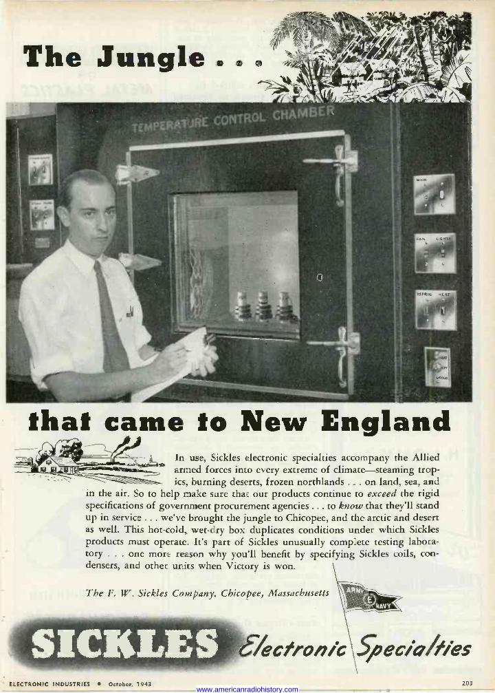
that came to New England In use, Sickles electronic specialties accompany the Allied
et armed forces into every extreme of climate-steaming trop- ics, burning deserts, frozen northlands ... on land, sea, and
in the air. So to help make sure that our products continue to exceed the rigid specifications of government procurement agencies ... to know that they'll stand up in service ... we've brought the jungle to Chicopee, and the arctic and desert as well. This hot -cold, wet -dry box duplicates conditions under which Sickles products must operate. It's part of Sickles unusually complete testing labora- tory ... one more reason why you'll benefit by specifying Sickles coils, con- densers, and other units when Victory is won.
The F. W. Sickles Company, Chicopee, Massachusetts
lecfronie ;.Speci4fies ELECTRONIC INDUSTRIES October, 1943 203
www.americanradiohistory.com

Try Dalis with those priority requirements. You'll be surprised.
Ample stocks provide prompt shipment on many items, partic- ularly resistors, con- densers, controls, wire, transformers, cable, headphones, relays, batteries, tubes, tools, etc.
And if required items are not in stock, DALIS go -gets 'em for you in shortest possible time.
Try DALIS - a de- pendable source of supply since 1925 - and an indispensable source today in get- ting things in a hurry.
Write, wire or 'phone..
H. L. DALIS, INc. Distributors of
RADIO & ELECTRONIC SUPPLIES 17 Union Square New York, N.Y.
Phones: ALgonquin 4-8112-3-4-5-6-7
lt
11
;I- --= I m IIIIIIIIIIIIIIIn INwJb'.j1101 N111Ìp111 kRny0111Ip.di piLn, II., M1., IgMlñ"19 ;..
114ie,¡ ' I'lll lüi -:::m i):'íì ,f
SERVICE tam
as October, 1941, functions to pro- vide a stable bombing platform upon which the possibility of pre- cision bombing depends. Operation of the device is controlled by the bombardier.
Dave Grimes Killed in Airplane Crash in Ireland
David Grimes, vice-president in charge of engineering for Philco Corp., who was abroad on a special war mis- sion, was killed on Saturday, Septem- ber 4, when the transport plane in which he was traveling with Commo- dore James A. Logan, Commandant of the United States Naval operating base at Londonderry, crashed into a mountain in Northern Ireland. He was 47 years of age.
Grimes served in the last war as chief radio officer at Kelly Field, Texas, when the use of radio in warfare was just beginning to assume importance. From June to December, 1918, he was Signal Officer attached to the British Air Forces at Aldershot and Little- hampton, England.
After the war, he joined A. T. Qr T. as a research engineer in telephony. In 1922 he established his own engi- neering organization to do research work on a consulting basis for a num- ber of different companies. It was dur- ing this period that he invented the famous "Grimes Inverse Duplex cir- cuit" that was used by many early radio amateurs in home-made receiv- ers. From 1930 until 1934, he was li- cense engineer with the Radio Corp. of America.
Mr. Grimes joined Philco in 1934 as engineer in charge of home radio -set research and engineering, and con- tinued in that capacity until 1939, when he was named chief engineer. In 1942 he was elected vice-president in charge of engineering.
Among Dave Grimes' many unusual abilities, he possessed a delightful platform presence, and whenever he was called on to address a meeting, the interest of either technical or lay audience was sure to be held until the very end, both by his flow of ideas and by his subtle and effective humor.
Friend Joins Curtiss-Wright
H. H. Friend, until recently asso- ciated with Scintilla Magneto divi- sion of the Bendix Aviation Corp., is now development engineer of electronics, airplane division de- partment, of the newly formed De- velopment division, Curtiss-Wright Corp., Bloomfield, N. J.
Anti -Climax Department Reports that revered technical
journal "Scientific American" in its September issue: "Electronics' brightest star, a demonstration of popping corn without heat."
ON
METAL, PLASTICS AND
STEEL STAMPING DIES
INQUIRIES SOLICITED
IFDWARe nsir ESTO / /.90/
121 BEACH ST. BOX 1672 BOSTON, MASS.
204 ELECTRONIC INDUSTRIES e October, 1943 www.americanradiohistory.com
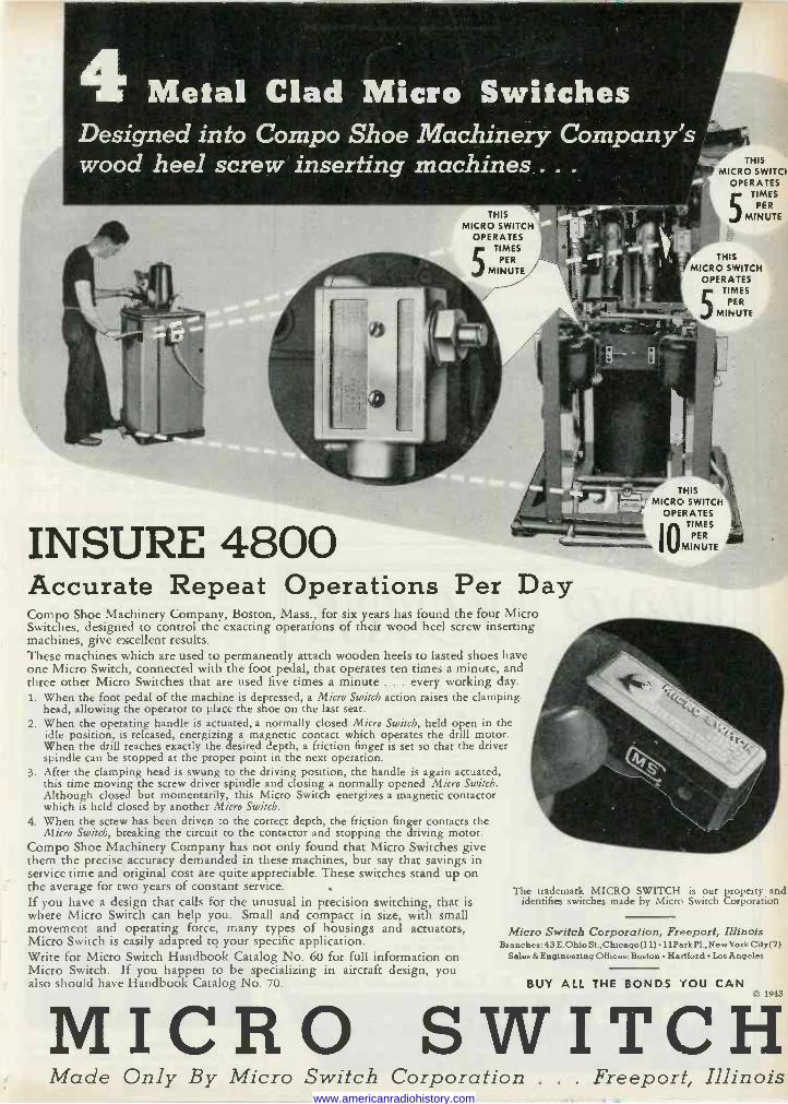
4 Metal Clad Micro Switches Designed into Compo Shoe Machinery Company's wood heel screw inserting machines... .
INSURE 4800 Accurate Repeat Operations Per Day Compo Shoe Machinery Company, Boston, Mass., for six years has found the four Micro Switches, designed to control the exacting operations of their wood heel screw inserting machines, give excellent results. These machines which are used to permanently attach wooden heels to lasted shoes have one Micro Switch, connected with the foot pedal, that operates ten times a minute, and three other Micro Switches that are used five times a minute ... every working day. 1. When the foot pedal of the machine is depressed, a Micro Switch action raises the clamping
head, allowing the operator to place the shoe on the last seat. 2. When the operating handle is actuated, a normally closed Micro Switch, held open in the
idle position, is released, energizing a magnetic contact which operates the drill motor. When the drill reaches exactly the desired depth, a friction finger is set so that the driver spindle can be stopped at the proper point in the next operation.
3. After the clamping head is swung to the driving position, the handle is again actuated, this time moving the screw driver spindle and closing a normally opened Micro Switch. Although closed but momentarily, this Micro Switch energizes a magnetic contactor which is held closed by another Micro Switch.
4. When the screw has been driven to the correct depth, the friction finger contacts the Micro Switch, breaking the circuit to the contactor and stopping the driving motor.
Compo Shoe Machinery Company has not only found that Micro Switches give them the precise accuracy demanded in these machines, but say that savings in service time and original cost are quite appreciable. These switches stand up on the average for two years of constant service. If you have a design that calls for the unusual in precision switching, that is identifies switches made by Micro Switch Corporation where Micro Switch can help you. Small and compact in size, with small movement and operating force, many types of housings and actuators, Micro Switch Corporation, Freeport, Illinois Micro Switch is easily adapted tq your specific application. Branches:43E.Olriost.,Chicago(11)11ParkPl.,NewYorkCity(7) Write for Micro Switch Handbook Catalog No. 60 for full information on Sales &Engineering Offices:Boston Hartford Los Angeles
Micro Switch. If you happen to be specializing in aircraft design, you also should have Handbook Catalog No. 70.
THIS MICRO SWITCI
OPERATES TIMES
PER
MINUTE
THIS MICRO SWITCH
OPERATES TIMES
PER
MINUTE
THIS MICRO SWITCH
OPERATES
Io TIMES
PER
MINUTE
The trademark MICRO SWITCH is our property and
BUY ALL THE BONDS YOU CAN 1943
MICRO SWITCH Made Only By Micro Switch Corporation . . . Freeport, Illinois
www.americanradiohistory.com
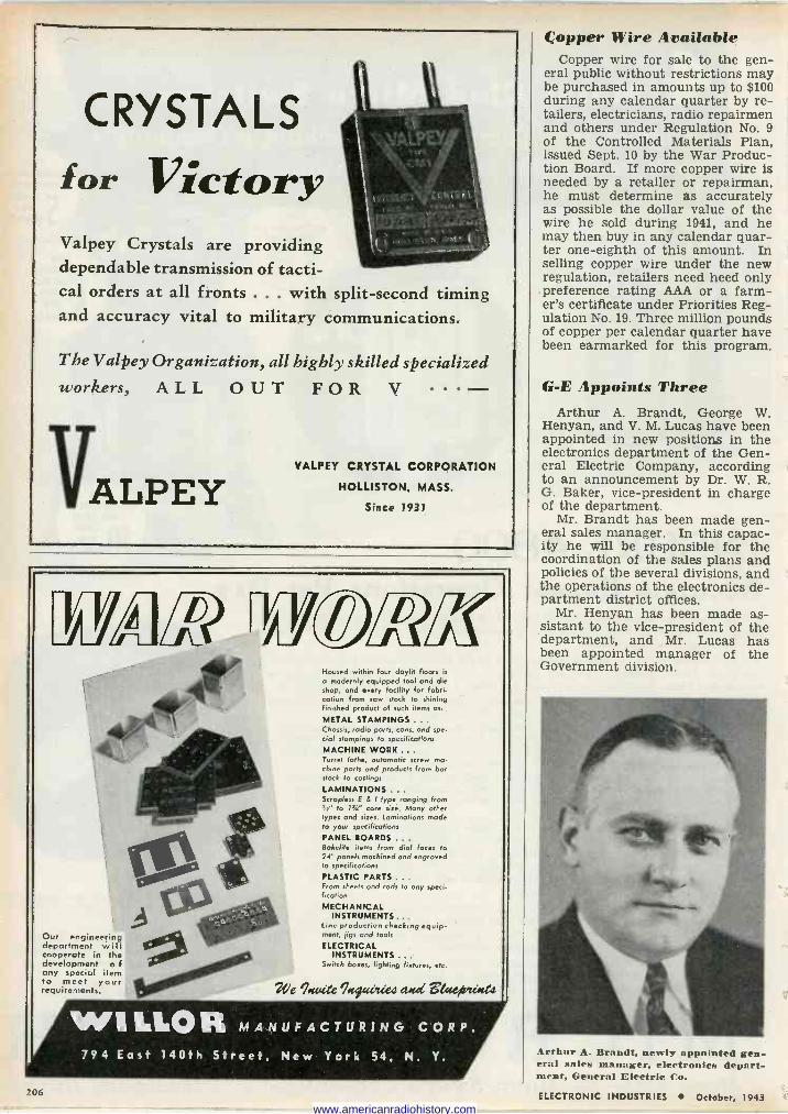
CRYSTALS
for Victory Valpey Crystals are providing dependable transmission of tacti- cal orders at all fronts ... with split-second timing and accuracy vital to military communications.
The Valpey Organization, all highly skilled specialized workers, ALL OUT FOR V
VALPEY VALPEY CRYSTAL CORPORATION
HOLLISTON, MASS.
Since 1931
EIWLfflIVL7
Our engineering department will cooperate in the development o f any special item to meet your requirements.
Housed within four daylit floors is
a modernly equipped tool and die shop, and every facility for fabri- cation from row stock to shining finished product of such items as, .
METAL STAMPINGS ... Chassis, radio parts, cans, and spe- cial stampings to specifications
MACHINE WORK ... Turret lathe, automatic screw ma- chine parts and products from bar stock to castings
LAMINATIONS ... Scropless E & 1 type ranging from
s" to Is/." core size. Many other types and sixes. Laminations made to your specifications
PANEL BOARDS ... Bakelite items from dial faces to 14" panels machined and engraved la specifications
PLASTIC PARTS ... From sheets and rods to any speci- fication
MECHANICAL INSTRUMENTS ...
Line production checking equip- ment, jigs and tools
ELECTRICAL INSTRUMENTS...
Switch boxes, lighting fixtures, etc.
2Ue %viee %uGclea a.cd $Gucipcücea
WI LILOR MANUFACTURING CORP.
Copper Wire Available Copper wire for sale to the gen-
eral public without restrictions may be purchased in amounts up to $100 during any calendar quarter by re- tailers, electricians, radio repairmen and others under Regulation No. 9 of the Controlled Materials Plan, issued Sept. 10 by the War Produc- tion Board. If more copper wire is needed by a retailer or repairman, he must determine as accurately as possible the dollar value of the wire he sold during 1941, and he may then buy in any calendar quar- ter one -eighth of this amount. In selling copper wire under the new regulation, retailers need heed only preference rating AAA or a farm- er's certificate under Priorities Reg- ulation No. 19. Three million pounds of copper per calendar quarter have been earmarked for this program.
G -E Appoints Three Arthur A. Brandt, George W.
Henyan, and V. M. Lucas have been appointed in new positions in the electronics department of the Gen- eral Electric Company, according to an announcement by Dr. W. R. G. Baker, vice-president in charge of the department.
Mr. Brandt has been made gen- eral sales manager. In this capac- ity he will be responsible for the coordination of the sales plans and policies of the several divisions, and the operations of the electronics de- partment district offices.
Mr. Henyan has been made as- sistant to the vice-president of the department, and Mr. Lucas has been appointed manager of the Government division.
794 East 140th Street, New York 54, N. Y.
206
Arthur A. Brnndt, newly appointed gen- eral sales manager, electronics depart- ment, General Electric Co.
ELECTRONIC INDUSTRIES October, 1943 www.americanradiohistory.com
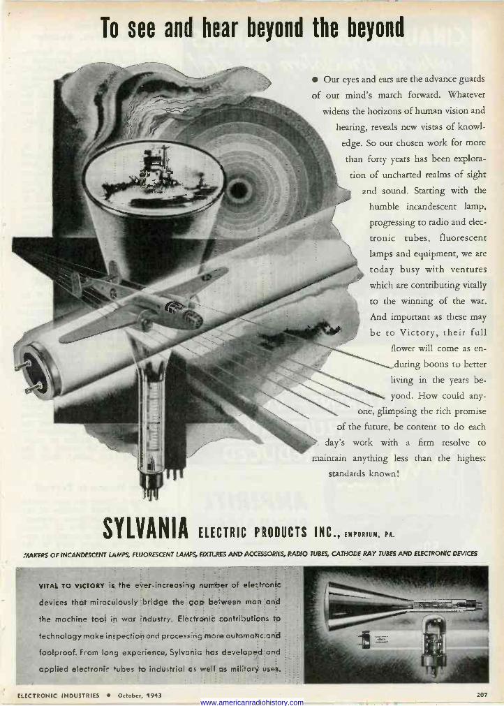
To see and hear beyond the beyond
Our eyes and ears are the advance guards
of our mind's march forward. Whatever
widens the horizons of human vision and
hearing, reveals new vistas of knowl-
edge. So our chosen work for more
than forty years has been explora-
tion of uncharted realms of sight
and sound. Starting with the
humble incandescent lamp,
progressing to radio and elec-
tronic tubes, fluorescent
lamps and equipment, we are
today busy with ventures
which are contributing vitally
to the winning of the war.
And important as these may
be to Victory, their full
flower will come as en-
during boons to better
living in the years be-
yond. How could any-
one, glimpsing the rich promise
of the future, be content to do each
day's work with a firm resolve to
maintain anything less than the highest
standards known!
SYLVANIA ELECTRIC PRODUCTS INC., EMPORIUM, PA.
MAKERS OF INCANDESCENT LAMPS, FLUORESCENT LAMPS, FaXTL PIS AND ACCESSORIES, RADIO TUBES, CATHODE RAY TUBES AND ELECTRONIC DEVICES
VITAL TO VICTORY is the ever-increasing number of electronic
devices that miractlously bridge the gap be wean mcn and
the machine tool in war ndustry. Electronic contributiols to
technology make inspection and process ng mare automa' c and
foolproof. From long experience, Sylvania has developed and
applied elertror0, tubes to industrial es well as m+l;tarr uses.
ELECTRONIC INDUSTRIES October, 1943 207 www.americanradiohistory.com
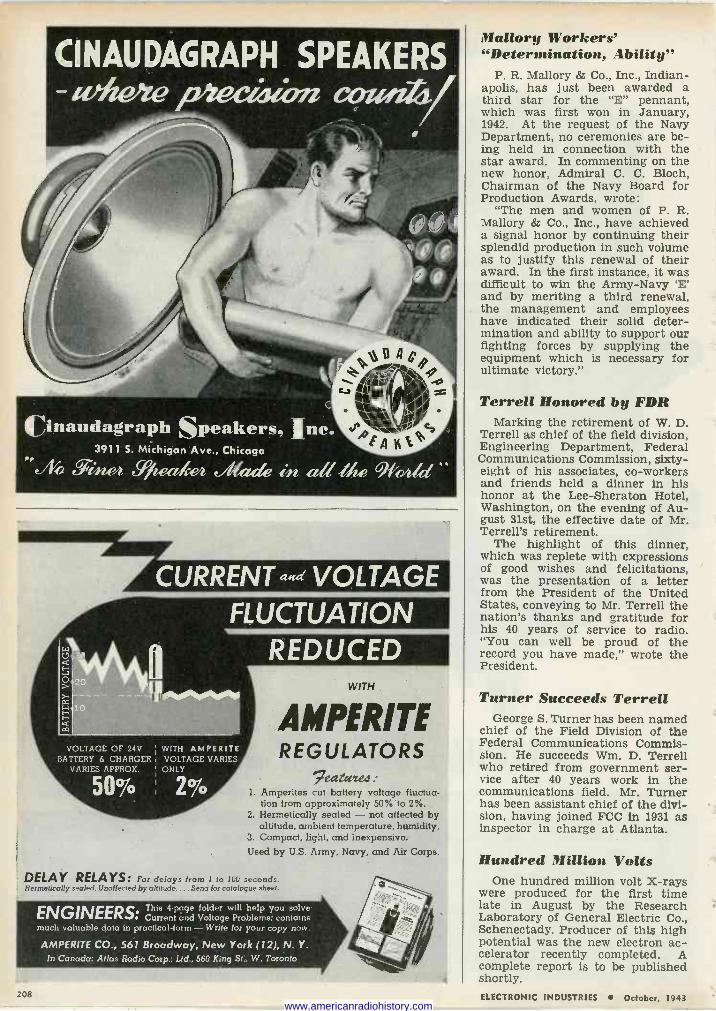
Cinaudagraph Speakers, Inc. 3911 S. Michigan Ave., Chicago Q 5711,eh FJ ealcey?, e ezek in, eta -Me h1ddd
CURRENT ned VOLTAGE
VOLTAGE OF 24V BATTERY 6 CHARGER,
VARIES APPROX.
5O%
FLUCTUATION REDUCED
WITH AMPERITE VOLTAGE VARIES ONLY
A MPERI TE REGULATORS
9eatwce4 1. Amperites cut battery voltage fluctua-
tion from approximately 50% to 2%. 2. Hermetically sealed - not affected by
altitude, ambient temperature, humidity. 3. Compact, light, and inexpensive. Used by U.S. Army, Navy, and Air Corps.
DELAY RELAYS: For delays from I to 100 seconds. Hermetically sealed. Unaffected by altitude...: Send for catalogue sheet.
ENGINEERS: This 4 -page folder will help you solve Current and Voltage Problems; contains
much valuable data in practical form - Write for your copy now.
AMPERITE CO., 561 Broadway, New York (12), N. Y. In Canada: Atlas Radio Corp.; Ltd., 560 King St., W. Toronto
208
Mallory Workers' "Determination, Ability"
P. R. Mallory & Co., Inc., Indian- apolis, has just been awarded a third star for the "E" pennant, which was first won in January, 1942. At the request of the Navy Department, no ceremonies are be- ing held in connection with the star award. In commenting on the new honor, Admiral C. C. Bloch, Chairman of the Navy Board for Production Awards, wrote:
"The men and women of P. R. Mallory & Co., Inc., have achieved a signal honor by continuing their splendid production in such volume as to justify this renewal of their award. In the first instance, it was difficult to win the Army -Navy `E' and by meriting a third renewal, the management and employees have indicated their solid deter- mination and ability to support our fighting forces by supplying the equipment which is necessary for ultimate victory."
Terrell Honored by FDR Marking the retirement of W. D.
Terrell as chief of the field division, Engineering Department, Federal Communications Commission, sixty- eight of his associates, co-workers and friends held a dinner in his honor at the Lee -Sheraton Hotel, Washington, on the evening of Au- gust 31st, the effective date of Mr. Terrell's retirement.
The highlight of this dinner, which was replete with expressions of good wishes and felicitations, was the presentation of a letter from the President of the United States, conveying to Mr. Terrell the nation's thanks and gratitude for his 40 years of service to radio. "You can well be proud of the record you have made," wrote the President.
Turner Succeeds Terrell George S. Turner has been named
chief of the Field Division of the Federal Communications Commis- sion. He succeeds Wm. D. Terrell who retired from government ser- vice after 40 years work in the communications field. Mr. Turner has been assistant chief of the divi- sion, having joined FCC in 1931 as inspector in charge at Atlanta.
Hundred Million Volts One hundred million volt X-rays
were produced for the first time late in August by the Research Laboratory of General Electric Co., Schenectady. Producer of this high potential was the new electron ac- celerator recently completed. A complete report is to be published shortly. ELECTRONIC INDUSTRIES October, 1943
www.americanradiohistory.com
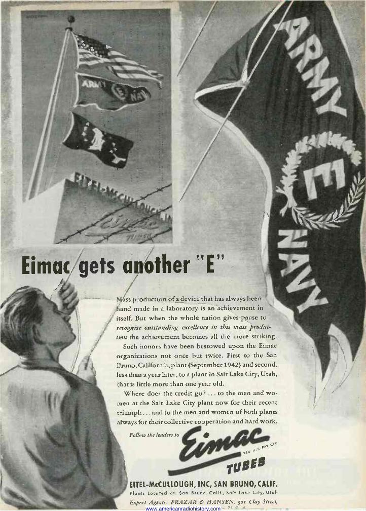
Emac gets another "E"
p'
Mess production of a device that has always been
hand made in a laboratory is an achievement in
itself. But when the whole nation gives pause to
recognize outstanding excellence in this mass produc-
tion the achievement becomes all the more striking.
Such honors have been bestowed upon the Eimac
organizations not once but twice. First to the San
Bruno, California, plant (September 1942) and second,
less than a year later, to a plant in Salt Lake City, Utah,
that is little more than one year old.
Where does the credit go? ... to the men and wo-
men at the Salt Lake City plant now for their recent
triumph ... and to the men and women of both plants
always for their collective cooperation and hard work.
Follow the leaders to
EITEL-McCULLOUGH, INC, SAN BRUNO, CALIF. Plants Locatted at: San Bruno, Calif., Salt Lake City, Utah
Export Ageuts,: FRAZAR & HANSEN, 3or Clay Street, www.americanradiohistory.com
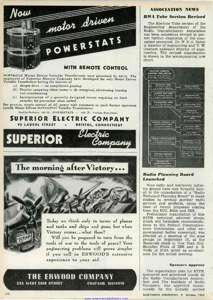
WITH REMOTE CONTROL POWERSTAT Motor Driven Variable Transformers were pioneered by SECO. The engineers of Superior Electric Company have developed the only Motor Driven Variable Transformer having the features of
(a) Simple drive - no complicated gearing. (b) Precise stopping when motor is de -energized, eliminating hunting
and overshooting. (c) Incorporation of a specially designed motor requiring no limit
switches for protection when stalled. For precise, simple control of AC power with automatic or push-button operation specify Motor Driven POWERSTAT Variable Transformers.
Send for Bulletins: 149 IE - POWERSTATS - 163 IE- Voltage Regulators
SUPERIOR ELECTRIC COMPANY 93 LAUREL STREET BRISTOL, CONNECTICUT
Today we think only in terms of planes and tanks and ships and guns, but when Victory comes ...what then?
Will you be prepared to turn from the tools of war to the tools of peace? Your engineering problems will prove simpler if you call in ERWOOD'S extensive experience to your aid.
THE ERW00D COMPANY 223 WEST ERIE STREET CHICAGO, ILLINOIS
210
ASSOCIATION NEWS
RMA Tube Section Revised The Electron Tube section of the
Engineering department of the Radio Manufacturers Association has been somewhat revised to per- mit further expansion of the com- mittee personnel. Dr. W. R. G. Baker is director of engineering and V. W. Graham assistant director of engi- neering. The revised organization is shown in the accompanying new chart.
EXECUTIVE COMMITTEE
ELECTRON TUBE SECTION Roger M. Wise, Chairman R. H. Fidler. ViceChoirman
RECEIVING TUBES A T. Week, Chairman
A. R. Wright. Vice...emnn
CATHODE RAY TUBES T. T Geld.mith, Chairman
1. E. Record, YicmChairmen
CHARACTERISTICS A. R. Wright. Chairmen
CHARACTERISTICS A. J. Norther. Chalrna.
TRANSMITTING TUBES O. W. Pihe. Che,rm.n CONVENTIONAL TYPES
C. DeW.N, Vi e.Chnemmen R. C. D.W.It. Ch.irmee
MAGNETRONS J. E. MM. Chairman
VELOCITY MODULATION TYPES
W. T. Coal., Chairman GASEOUS CONTROL AND
CONVERSION TUBES D. D. Enoalo., Chairman TNERMIONIC TYPES
A. C. Gavle VIc.Chairman D. r. Edmard , ChaG .n
POOL TYPES . C. Gable Chairmen
L VACUUM SEALED DEVICES PHOTOSENSITIVE TYPES
U E. Marshall, V.ceCharom J. N. Hutchings. Chairmen
TYPE DESIGNATIONS S. Vu rep, Cheirmon
MECHANICAL STANDARDIZATION E. . Chairman
MISCELLANEOUS DEVICES. D. E. Mar.Mll, Chairman
'Gap., Capacitor, Smile M.: S.n,tching Y,»..; aalla.M;
Lead lamp., Etc.
Radio Planning Board Launched
Nine radio and electronic indus- try groups have now formally join- ed in the organization of a "Radio Technical Planning Board" to make studies to develop postwar radio services and products, along the lines of recent proposals coming from the FCC, RMA and IRE.
Preliminary organization of this RTPB technical advisory group, which will formulate recommenda- tions to the Federal Communica- tions Commission and other ex - government bodies concerned, was effected at a meeting of the nine groups on September 15, at the Roosevelt Hotel in New York City. Haraden Pratt of IRE and A. S. Wells of RMA acted as co-chair- men for the initial meeting.
Sponsors approve The organization plan for RTPB,
sponsored and presented jointly by the Radio Manufacturers Associa- tion and The Institute of Radio Engineers, was approved unani- mously by the initially invited ELECTRONIC INDUSTRIES October, 1943
www.americanradiohistory.com
ONE OF A SERIES OF ADVERTISEMENTS SLOWING DeJUR PRECISION PRODUCTS IN I CT ON ON THE HOME FRONT
Because of the secrecy encircling war production, little can be told of a meter's im- portance to almost every phase of the work. Suffice it to say that over a wide range of industrial electronic applications ... heat treating, counting, refining, sound de-
tection, color selection, and many others about which not a word has been spoken or written ... electrical measuring instruments are universally used.
It is of interest to know ... for present and future reference ... that DeJur precision meters are built into the equipment employed by many war plants. Wherever used, these meters enjoy confidence from the standpoint of sensitivity, durability and dependability. Peace will usher in even more new uses for meters. To insure absolute satisfaction, specify DeJur.
Send your blood out to fight... donate a pint to the Red Cross today
Demi: geNtRAImi,_MSCO Awarded the Army -Navy ^E" for High Achievement SHELTON, CONNECTICUT
k E W YORK PLANT : 99 Hudson Street, New York City CANADIAN SALES OFFICE: 560 King Street West. Toronto
ELECTRONIC INDUSTRIES October, 1943 211 www.americanradiohistory.com
enteetIo-ttel lor u atth
BU -TON TYPE. FLAT OR STEPPED TYPE
SQUARE, OBLONG AND ROUND
CLOSEST TOLERANCES
EXCELLENT FINISH
MINIMUM LAPPING GREAT SAVINGS IN MAN HOURS
AND COSTS
FROMPT DELIVERIES Send for full information
-Jes teae Compatie UNION, NEW JERSEY
(cm:wish° THE "Nth" DEGREE Perfect co-ordination of skilled minds and hands h a weh knit organization with 20 years of radio manufacturing experience has been the secret of MERIT'S success in building precision equipment to the most exacting specifications.
Now manufacturing for every branch of the Armed Services.
Enlarged facilities enabl to offer prompt shipmen priority orders.
Since 1924
Transformers- Coils- Reactors - Electrical Windings of All Types
for the Radio Trade and other Electronic Applications.
MERIT COIL & TRANSFORMER CORP. .-3j i North Desplaines St. CHICAGO 6, U.S.A.
"sponsors." These included, in ad- dition to the RMA and IRE, the following:
American Institute of Electrical Engineers
American Institute of Physics American Radio Relay League FM Broadcasters, Inc. International Association of
Chiefs of Police National Association of Broad-
casters National Independent Broadcast-
ers. Other "sponsors" are expected to
join RTPB later for work on many technical projects, including utiliza- tion of the broadcast spectrum and systems standardization for many public radio services, including tele- vision and frequency modulation.
Elections and assignments The general plan for organiza-
tion of RTPB, approved unanimous- ly at the New York meeting on September 15, was to be developed in detail at another meeting to be held in New York on September 29. Paul V. Galvin, president of RMA and Dr. Lynde P. Wheeler, presi- dent of IRE, issued the invitations for the meeting of September 29, called to arrange detailed panel and other organization procedures, including the election of a general chairman and officers.
Motion Picture Engineers Discuss Tube Applications
Application of electronic prin- ciples to the motion picture indus- try are to come in for a large share of the program for the fifty-fourth semi-annual technical conference of the Society of Motion Picture Engineers. The gathering will be held in Hollywood's Hollywood - Roosevelt hotel Oct. 18 to 22 in- clusive.
Thirty technical papers have been scheduled for presentation. They cover a wide range of sub- jects, including acoustical research, sound recording, postwar television planning, new types of cameras, amplifiers and speakers. Among papers having to do more specific- ally with vacuum tube applications are: "Postwar television planning and requirements," by Klaus Lands- berg, Television Productions, Para- mount Studios; "An improved light valve checking device," by James P. Corcoran, Twentieth Century - Fox Studio; "Improvements in sound - recording equipments," by Dr. L. F. Brown, Western Electric Co. Dr. H. F. Olsen, research en- gineer of the RCA Laboratories will discuss acoustical research and an- other RCA engineer will describe recent sound recording installa- tions in Washington, including RCA's 35 mm studio recorder.
212 ELECTRONIC INDUSTRIES October, 1943 www.americanradiohistory.com
ELECTRONIC INDUSTRIES October, 1943 213 www.americanradiohistory.com
QUALITY SINCE 1920
.,sentinel RADIO
214
TRANSFORMER
Precise . . Simple
PERMEABILITY -TUNED
CAMBRIDGE THERMIONIC
CORP. 44s CONCORD AVE. CAMBRIDGE, MASS.
GUNS'` ,
N - FIRING' -ASEC +
,t , J
t
* When the "cease firing order is flashed to our fighting men, we'll get to know in detail the vital part that radio played in winning the Victory. Then, the same dependable performance given on the battlefield by Sentinel -built
equipment will be reflected in new peace- time models... models which will flow from Sentinel's factory lines, now fully utilized for war production. Then Sentinel dealers once again will be able to supply outstand- ing values in the radio and electronic field -battle -tested equipment in modern -as -
tomorrow designs that will please and sell.
SENTINEL RADIO CORPORATION 2020 Ridge Avenue, Evanston, III.
Electronic Subjects Interest Electrical Engineers' Meeting
The following papers were among those presented at the National Technical Meeting of the American Institute of Electrical Engineers, September 2-4, at Salt Lake City, Utah.
"Radio Noise Elimination in All - Metal Aircraft" by Fred Foulon, Douglas Aircraft Co., El Segundo, Calif. Effective means to reduce radio noise due to the electric equipment of the plane were dis- cussed.
"Application of 720 -Cycle Car- rier to Power Distribution Circuits" by J. L. Woodworth, General Elec- tric Co. Approximate methods to evaluate the transmission charac- teristics of 720 -cycle waves over power systems are investigated and found to be in good agreement with measurements.
"Electronic Control of D -C Mo- tors" by K. P. Puchlowski, West- inghouse Electric and Mfg. Co. Some characteristics of a rectifier - motor system are investigated.
"Aircraft Transformers" by O. Kiltie, General Electric Co.
"Parallel Operation of Airplane Alternators" by D. W. Exner, West- inghouse Electric and Mfg. Co.
Control of Gas Cutters A new means of electronically
controlling the steering motor of a gas flame cutting machine was de- scribed by R. D. McComb, indus- trial control division of the General Electric Co., at the Chicago meet- ing (Oct. 18-21) of the American Welding Society. The equipment is a photo -electric template control in which the scanning motor is controlled in response to a signal from a scanning head. A new type of recording equipment designed to facilitate comparisons between a test weld and a weld made on the job was described by J. Van den Beemt and J. R. Fetcher of the E. G. Budd Mfg. Co.
RMA-IRE Fall Meeting Radio Manufacturers Association
Engineering Department and the Institute of Radio Engineers, to- gether, will hold their Rochester (N. Y.) fall meeting in the form of a War Radio Conference at the Sagamore Hotel, Nov. 8 and 9. Technical sessions will present the following papers:
Demountable vs. sealed -off tubes, by I. E. Mouromtseff, Westinghouse Electric & Mfg. Co.
Recent advances in Klystron theory, by William W. Hansen, Sperry Gyroscope Co.
Design of if transformers for FM modulation receivers, by William H.
ELECTRONIC INDUSTRIES October, 1943
www.americanradiohistory.com
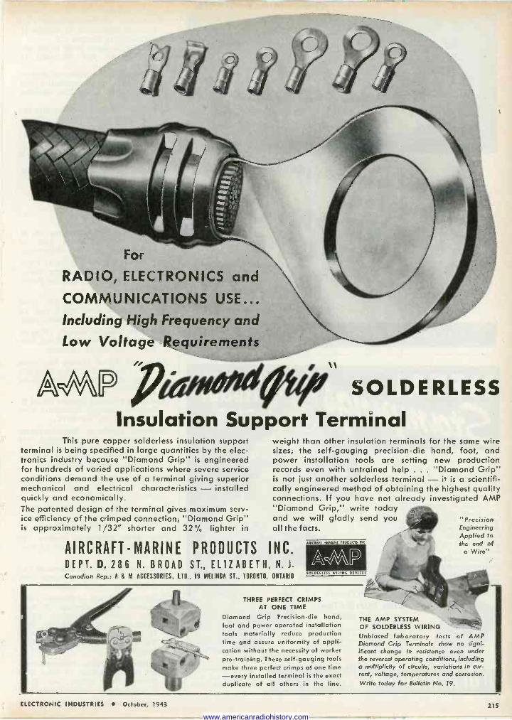
For
RADIO, ELECTRONICS and
COMMUNICATIONS USE... Including High Frequency and
Low Voltage Requirements
AWP SOLDERLESS Insulation Support Terminal
This pure copper solderless insulation support terminal is being specified in large quantities by the elec- tronics industry because "Diamond Grip" is engineered for hundreds of varied applications where severe service conditions demand the use of a terminal giving superior mechanical and electrical characteristics - installed quickly and economically. The patented design of the terminal gives maximum serv- ice efficiency of the crimped connection; "Diamond Grip" is approximately 1/32" shorter and 32% lighter in
weight than other insulation terminals for the same wire sizes; the self -gauging precision -die hand, foot, and power installation tools are setting new production records even with untrained help . . . "Diamond Grip" is not just another solderless terminal - it is a scientifi- cally engineered method of obtaining the highest quality connections. If you have not already investigated AMP "Diamond Grip," write today and we will gladly send you all the facts.
AIRCRAFT -MARINE PRODUCTS INC. DEPT. D, 286 N. BROAD ST., ELIZABETH, N. J.
Canadian Rep.: A & M ACCESSORIES, LTD., 19 MELINDA ST., TORONTO, ONTARIO
AISCSAR MIASINF P[ODUCIS INC.
SOLDEPEESS WISING DEVICES
THREE PERFECT CRIMPS AT ONE TIME
Diamond Grip Precision -die hand, foot and power operated installation tools materially reduce production time and assure uniformity of appli- cation without the necessity of worker pre -training. These self -gauging tools make three perfect crimps at one time -every installed terminal is the exact duplicate of all others in the line.
THE AMP SYSTEM OF SOLDERLESS WIRING Unbiased laboratory tests of AMP Diamond Grip Terminals show no signi- ificant change in resistance even under the severest operating conditions, including a multiplicity of circuits, variations in cur- rent, voltage, temperatures and corrosion. Write today for Bulletin No. 19.
"Precision Engineering Applied to the end of
a Wire"
ELECTRONIC INDUSTRIES October, 1943 215
www.americanradiohistory.com
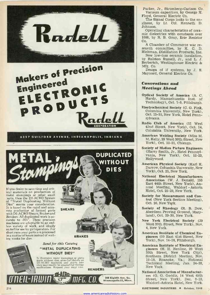
Milkers of Precision
Engineered ELECTRONIC PRODUCTS «dell- 6327 GUILFORD AVENUE, INDIANAPOLIS, INDIANA
If you desire to save time and crit- ical materials on production of metal stampings or other small carts, then the DI -ACRO System of "Metal Duplicating Without Dies" merits your consideration. It is based on the rapid and accu- rate productior of formed parts with DI -ACRO Shears, Brakes and Benders. All duplicated work is ac- curate to .001". These precision machines are adaptable to an end- less variety of work, and ideally su_ted for use by girl operators. For short runs your parts are processed in a matter of hours instead of wait- ing weeks for dies.
.nta ovaart+ ï -- .- l
SHEARS
BRAKES
Send for this Catalog "METAL DUPLICATING
WITHOUT DIES" It illustrates many stampings or parts made without dies, gives full details on DI -ACRO machines and shows how they may readily be adapted for various applications. Request your copy now.
D"11EIL-IRIU111 L./. ILÀL
4lON MAC
BENDERS
111 FG. CO. 348 Eighth Ave. So.
Minneapolis 15, Minn.
Parker, Jr., Stromberg -Carlson Co. Vacuum capacitors, by George H.
Floyd, General Electric Co. The Signal Corps looks to the en-
gineer, by Lt. Col. Kenneth D. Johnson.
Operating characteristics of cera- mic dielectrics with constants over 1000, by R. B. Gray, Erie Resistor Co.
A Chamber of Commerce war re- search committee, by K. C. D. Hickman, Distillation Products, Inc.
New low -loss ceramic insulation, by Ralston Russell, Jr., and L. J. Berberich, Westinghouse Electric & Mfg. Co.
Design of if systems, by J. E. Maynard, General Electric Co.
Conventions and Meetings Ahead Optical Society of America (A. C.
Hardy, Massachusetts Inst. of Technology), Oct. 7-9, Pittsburgh.
Electrochemical Society (C. G. Fink, Columbia University, New York), Oct. 13-16, New York, Hotel Penn- sylvania.
Radio Club of America (11 West 42nd Street, New York), Oct. 14, Columbia University, New York.
American Welding Society (Miss M. M. Kelly, 29 West 39th Street, New York), Oct. 18-21, Chicago.
Society of Motion Picture Engineers (Harry Smith, Jr., Hotel Pennsyl- vania, New York), Oct. 18-22, Hollywood.
American Physical Society (Karl K. Darrow, Columbia University, New York), Oct. 23, New York.
National Electrical Manufacturers Association (W. J. Donald, 155 East 44th Street, New York), An- nual Meeting, Waldorf - Astoria Hotel, Oct. 25-29, New York.
Society for Measurement and Con- trol (New York Section Meeting), Oct. 26, New Yqrk.
Society of Rheology (R. B. Dow, Aberdeen Proving Ground, Mary- land), Oct. 29-30, New York.
New York Electrical Society (29 West 39th Street, New York), Nov. 4, New York.
American Institute of Chemical En- gineers (50 East 41st Street, New York), Nov. 14-16, Pittsburgh.
American Institute of Electrical En- gineers (H. H. Henline, 29 West 39th Street, New York City), Southern District Meeting, Nov. 16-18, Roanoke, Va.; National Technical Meeting, Jan. 24-28, New York.
National Association of Manufactur- ers (G. G. Geddis, 14 West 49th Street, New York), Dec. 8-10, Waldorf-Astoria Hotel, New York.
216 ELECTRONIC INDUSTRIES October, 1943
www.americanradiohistory.com
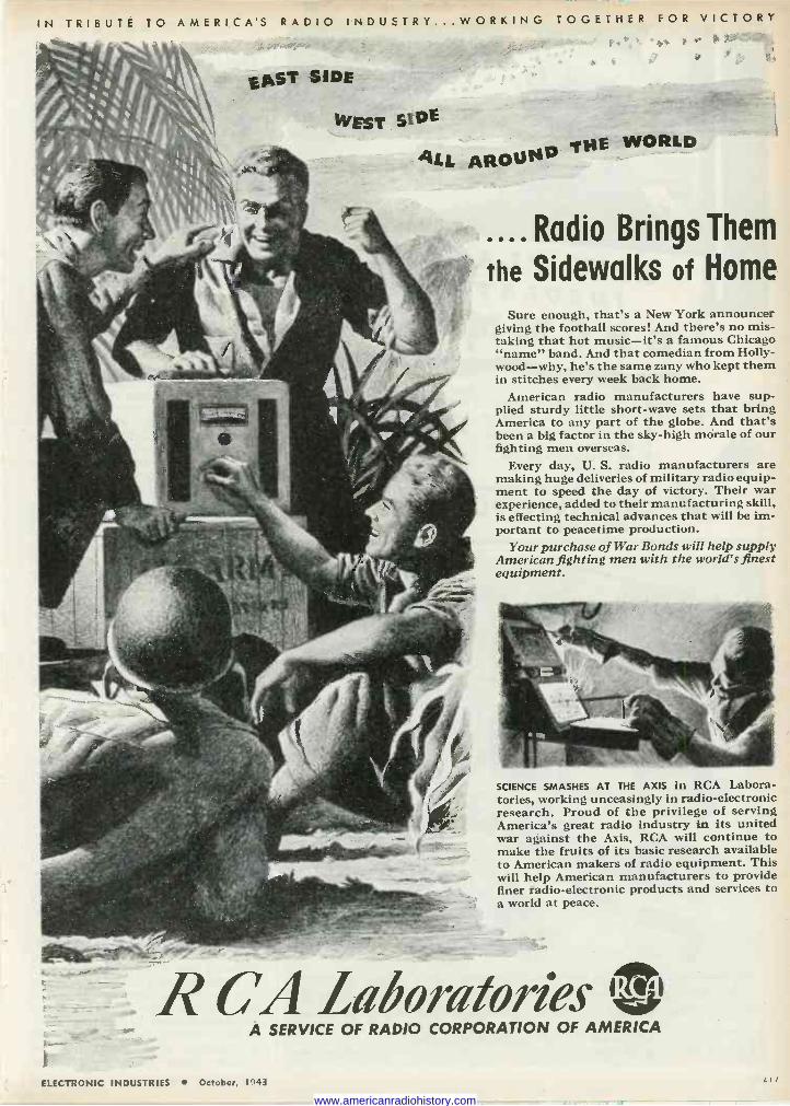
IN TRIBUTE TO AMERICA'S RADIO INDUSTRY ...WORKING TOGETHER FOR VICTORY
EAST SIDE
WEST SIDE
ALL AROUND THE WORLD
f+ we;i
....Radio Brings Them
the Sidewalks of Home
Sure enough, that's a New York announcer giving the football scores! And there's no mis- taking that hot music-it's a famous Chicago "name" band. And that comedian from Holly- wood-why, he's the same zany who kept them in stitches every week back home.
American radio manufacturers have sup- plied sturdy little short-wave sets that bring America to any part of the globe. And that's been a big factor in the sky-high morale of our fighting men overseas.
Every day, U. S. radio manufacturers are making huge deliveries of military radio equip- ment to speed the day of victory. Their war experience, added to their manufacturing skill, is effecting technical advances that will be im- portant to peacetime production.
Your purchase of War Bonds will help supply American fighting men with the world's finest equipment.
SCIENCE SMASHES AT THE AXIS in RCA Labora- tories, working unceasingly in radio -electronic research. Proud of the privilege of serving America's great radio industry in its united war against the Axis, RCA will continue to make the fruits of its basic research available to American makers of radio equipment. This will help American manufacturers to provide finer 'radio -electronic products and services to a world at peace.
R GA Laboratories e A SERVICE OF RADIO CORPORATION OF AMERICA
ELECTRONIC INDUSTRIES October, 1`',43
www.americanradiohistory.com
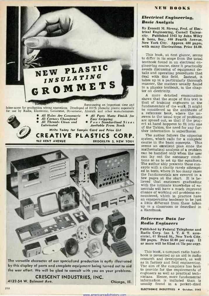
Announcing an important time and labor -saver for production wiring operations. Developed of 100% phenolic plastic especially for use by Radio, Electronic, Generator, Dynamotor, Aircraft and other manufacturers.
All Holes Are Concentric All Corners Chamfered All Threads Clean and Lubricated
All Parts Matte Finish for Easy Gripping Four Standardized Size s Available From Stock
Write Today for Sample Card and Price List
CREATIVE PLASTICS CORP. 962 KENT AVENUE BROOKLYN 5, NEW YORK
The versatile character of our specialized production is aptly illustrated by this display of parts and complete equipment being turned out to aid the war effort. We will be glad to consult with you on your problems.
CRESCENT INDUSTRIES, INC. 4132-54 W. Belmont Ave.
213
Chicago, Ill.
NEW BOOKS
Electrical Engineering, Basic Analysis By Everett M. Strong, Prof. of Elec- trical Engineering, Cornell Univer- sity. Published 1943 by John Wiley & Sons, Inc., 440 Fourth Avenue, New York City. Approx. 400 pages, with many illustrations. Price $4.00.
This book, at first glance, seems to differ in its scope from the usual textbook found in an electrical en- gineering course, since it practically avoids discussing of equipment de- tails and operating procedures that deal with this field. Instead, it takes up in a particularly thorough manner, the matters usually found in a physics textbook, in the chap- ter on electricity.
A more detailed examination shows that the scope of this text is that of training engineers in the fundamentals of the work. It might be considered as the antithesis of a reference book, where the an- swers to the usual type of problems are spread out, so that if the proj- ect at hand happens to fit into one of the Tables, the need for any fur- ther information is superfluous.
The author follows the opposing system, which calls for a complete course in the basic concepts. This seems an excellent plan since the mathematical analysis of a problem can be handled only when the user can lay out the necessary condi- tions so as to set up the equations. The author ably presents these con- cepts with a clarity rarely attempt- ed in tests, where in too many cases the fundamentals are covered in a few pages at the start. It is be- lieved that engineers graduating with the intimate knowledge of es- sentials will have a much improved chance of working out problems en- countered, which in practice have an exasperating tendency to be just a little different from these taken up in a classroom or described in a Handbook.
Reference Data for Radio Engineers Published by Federal Telephone and Radio Corp. (an I. T. & T. asso- ciate), 67 Broad St., New York City. 200 pages. Price S1.00 per copy. 12 or more will be filled at 75c per copy.
This book, a compact radio hand- book is presented as an aid in radio research and development, as well as in factory and field engineering. The aim of the compilers has been to provide for the requirements of engineers as well as practical tech- nicians. Hence, more fundamental information is included than is usually found in a pocket -sized ELECTRONIC INDUSTRIES October, 1943
www.americanradiohistory.com
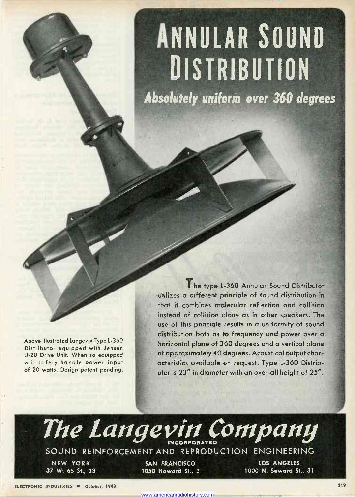
Above illustrated Langevin Type L-360 Distributor equipped with Jensen U-20 Drive Unit. When so equipped will safely handle power input of 20 watts. Design patent pending.
Absolutely uniform over 360 degrees
The type L-360 Annular Sound Distributor utilizes a different arinciple of sound distribution n
that it combines riolecular reflection and collisicn instead of colsior alone as in other speakers. The
use of this prilciple results in a uniformity of sound
distribution both as to frequency and power over a
n.orzontal plane of 363 degrees and a vertical plane of approximately d- degrees. Acoustücal output char- acteristics ova fable on request. Type L-360 Distrib- utor is 23" in diameter with an over-all height of 25".
TheangevinL INCORPORATED
SOUND REINFORCEMENT AND REPRODLC1ÍION ENGINEERING NEW YORK
37 W. 65 St., 23 SAN FRANCISCO LOS ANGELES
1050 Howard St., 3 1000 N. Seward St., 31
ELECTRONIC INDUSTRIES October, 1943 219
www.americanradiohistory.com
MANUFACTURING COMPANY, INC.
SIGNAL GENERATORS - AUDIO OSCILLATORS - TEST EQUIPMENT RADIO RECEIVERS - TRANSMITTERS - ELECTRONIC DEVICES
n, cd b. . N t: A II 2 F: 1. T 1 \ I.. t It N e l' It t l \ C
poo vio
305 EAST 63rd STREET NEW YORK CITY, N. Y, Telephone: R E g e n t 7-3090
WHEN and AS you want it Complete graduation of light-from bright through interme- diate glows to total dark within 90' rotation of the shutter is a feature of this Gothard Series 430 Shutter Type Pilot Light. Particularly applicable for aircraft, marine, signal and similar applications that require various intensities of light under constantly changing conditions. Sturdy construction-rigid non -short terminals-faceted or plain jewels. Also available with polarized lens. Colors : red, green, amber, blue or opal.
Ask for complete information
and prices
MANUFACTURING COMPANY 1315 NORTH NINTH STREET, SPRINGFIELD, ILLINOIS
220
(53% in. x 8% in.) radio handbook. A small First Edition of Reference
Data for Radio Engineers was pre- pared for presentation to the Army and Navy, government agencies, educational institutions and engi- neers on the staff of the Interna- tional Telephone and Telegraph Corporation and its associate com- panies. Now available for general distribution at a price of $1.00 per copy.
Experiments in Electronics and Communication Engineering By E. H. Schulz and L. T. Ander- son, both of the Illinois Institute of Technology, Chicago. Published (1943) by Harper & Brothers, New York City. 381 pages. Price, $3.00
A guide to laboratory experiments and methods in the measurements and processes commonly used in electronic and ultra -high frequency radio technic. It is important that the persons starting the study of electrical and radio methods be- come acquainted with actual equip- ment and the ways with which it car be handled and tested, early in the course. This manual con- taining more than one hundred well selected and described labora- tory experiments, will provide an important part of any training program.
Electronic Control of Reistance Welding By Geo. M. Chute, Application En- gineer, General Electric Co. Pub- lished by McGraw-Hill Book Co., New York City, 1943. 389 pages. Price $4.00.
A practical manual on the oper- ating principles of welding control in all its phases. The treatment is thorough and can be used by engi- neers and operators alike in study- ing process control for which it pro- vides a useful introduction to the use of electron tubes in timing problems.
Electronic Physics By L. Grant Hector, Herbert S. Lein and Clifford E. Scouten. Published by the Blakiston Co., Philadelphia, 1943, 355 pages, $3.75.
Intended as an elementary text- book for college courses in elec- tronic processes and associated fields, the book gives a short survey of the various subjects treated. Chapters on ac circuits, electrolysis, batteries, magnetism, dc and elec- tron tube circuits, geometrical op- tics, photoelectricity and radioac- tivity are included.
Basic laws are stated and illus- trated in black -an -white diagrams, ELECTRONIC INDUSTRIES October, 1943
www.americanradiohistory.com
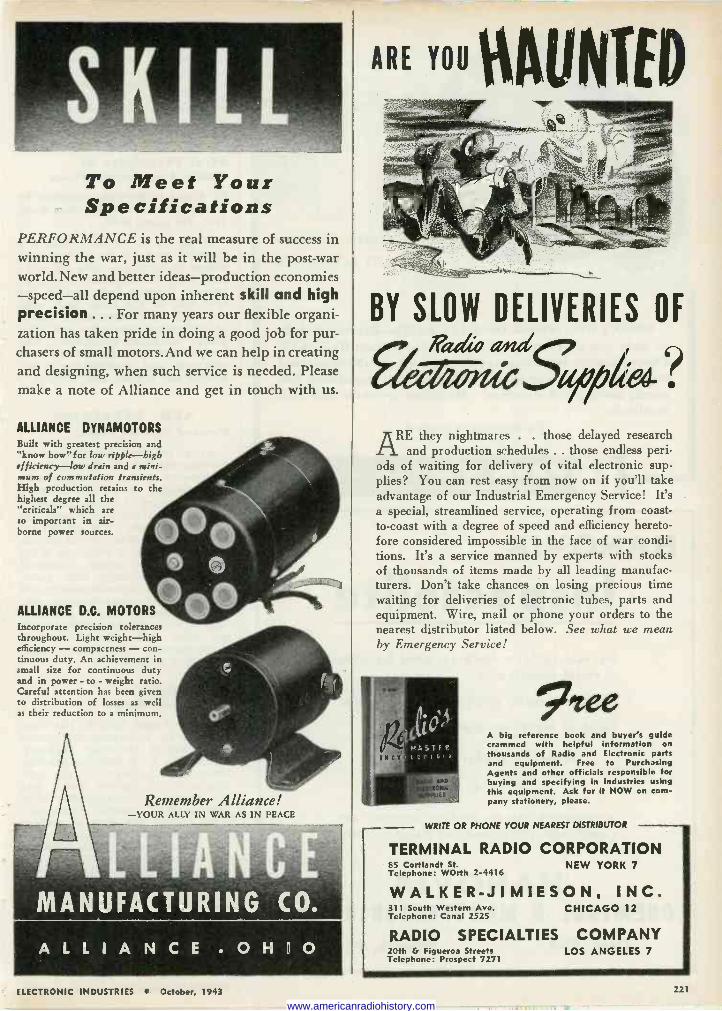
To Meet Your Spe cifications
PERFORMANCE is the real measure of success in winning the war, just as it will be in the post-war world. New and better ideas-production economies -speed-all depend upon inherent skill and high precision ... For many years our flexible organi- zation has taken pride in doing a good job for pur- chasers of small motors. And we can help in creating and designing, when such service is needed. Please make a note of Alliance and get in touch with us.
ALLIANCE DYNAMOTORS Built with greatest precision and "know how" for low ripple-high efficiency-low drain and a mini- mum of commutation transients. High production retains to the highest degree all the "criticals" which are so important in air- borne power sources.
ALLIANCE D.C. MOTORS Incorporate precision tolerances throughout. Light weight-high efficiency - compactness - con- tinuous duty. An achievement in small size for continuous duty and in power - to - weight ratio. Careful attention has been given to distribution of losses as well as their reduction to a minimum.
Remember Alliance! -YOUR ALLY IN WAR AS IN PEACE
ALLIANCE . O H I O
ARE YOU ettUNTED rY:..
BY SLOW DELIVERIES OF
Aada wuG
REthey nightmares . . those delayed research and production schedules . . those endless peri-
ods of waiting for delivery of vital electronic sup- plies? You can rest easy from now on if you'll take advantage of our Industrial Emergency Service! It's a special, streamlined service, operating from coast - to -coast with a degree of speed and efficiency hereto- fore considered impossible in the face of war condi- tions. It's a service manned by experts with stocks of thousands of items made by all leading manufac- turers. Don't take chances on losing precious time waiting for deliveries of electronic tubes, parts and equipment. Wire, mail or phone your orders to the nearest distributor listed below. See what we mean by Emergency Service!
7tee A big reference book and buyer's guide crammed with helpful information on thousands of Radio and Electronic parts and equipment. Free to Purchasing Agents and other officials responsible for buying and specifying in industries using this equipment. Ask for it NOW on com- pany stationery, please.
WRITE OR PHONE YOUR NEAREST DISTRIBUTOR
TERMINAL RADIO CORPORATION 85 Cortlandt St. NEW YORK 7 Telephone: WOrth 2-4416
WALKER-JIMIESON. INC. 311 South Western Ave. CHICAGO 12 Telephone: Canal 2525
RADIO SPECIALTIES COMPANY 20th G Figueroa Streets LOS ANGELES 7 Telephone: Prospect 7271
ELECTRONIC INDUSTRIES October, 1943 221
www.americanradiohistory.com
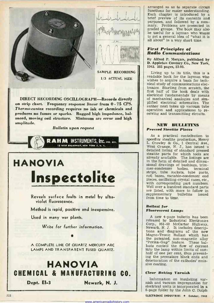
ú
fr
SAMPLE RECORDING
1/3 ACTUAL SIZE
DIRECT RECORDING OSCILLOGRAPH-Records directly on strip chart. Frequency response linear from 0 - 75 CPS. Thermo -cons ax recording requires no ink or chemicals and produces no fumes or sparks. Rugged high impedance, bal- anced, moving coil structure. Minimum arc error and high amplitude.
Bulletin upon request
RAHM INSTRUMENTS, Inc. IND. DIV.
12 WEST BROADWAY, NEW YORK 7, N. Y.
HANOVIA
Inspectolite Reveals surface faults in metal by ultra-
violet fluorescence.
Method is rapid, positive and inexpensive.
Used in many war plants.
Write for further information.
A COMPLETE LINE OF QUARTZ MERCURY ARC LAMPS AND TRANSPARENT FUSED QUARTZ.
HANOVIA CHEMICAL & MANUFACTURING CO.
Dept. El -3 Newark, N. J.
222
arranged so as to separate circuit functions for easier understanding. Each chapter is introduced by a brief preview of its contents and purposes, and followed by a sum- mary. Problems are presented in graded groups. The book may also be useful for a layman who wants to get a general idea of "what it is all about" in a very short time.
First Principles of Radio Communications By Alfred P. Morgan, published by D. Appleton Century Co., New York, 1943. 353 pages, $3.00.
Living up to its title, this is a readable book for the layman who wishes to acquire a basis for tech- nical study of communications elec- tronics. Starting from scratch, the first half of the book deals with electrical fundamentals by means of mechanical analogies and sim- plified electrical schematics. The author next takes up vacuum tube operation and applications to re- ceiving and transmitting circuits.
NEW BULLETINS Pressed Steatite Pieces
As a practical contribution to speedier steatite production, Henry L. Crowley & Co., 1 Central Ave., West Orange, N. J., has issued a detailed listing of standard pressed steatite parts for which tools are already available. The listings are in the form of detailed and dimen- sional drawings of bushings, trim- mer -condenser bodies, terminal strips, tube sockets, tube parts, coil bases, variable -condenser end pieces, oscillating -crystal cases, etc., with corresponding part numbers. Well over a hundred standard parts are listed, with more to follow in supplementary bulletins issued from time to time.
Ballast for Fluorescent Lamps
A new 4 -page bulletin has been released by Industrial Electronics Corp., 951-63 McCarter Highway, Newark, N. J. It includes descrip- tions and diagrams of the new Magno-Tronic Ballast which has the patented, non-magnetic alloy "Perma-Gap" feature. These bal- lasts control the flow of current into the lamp within limits of one- half of one per cent, thus prevent- ing the premature black ends and deterioration of the cathodes' emis- sive coating.
Clear Baking Varnish Information on insulating var-
nish and vacuum impregnation for electrical units is incorporated in a 6 -page folder by the John C. Dolph ELECTRONIC INDUSTRIES October, 1943
www.americanradiohistory.com
{
The
world to corne
irg in the IN SHE th OgE
That's right. You guessed it: the electron.The war's demand for instant mastery of every method of com- munication has matured the science of electronics. When peace is won, the world will be in for a host of revolutionary surprises.
Stancor transformers are now doing a ¡ob for war . . . organizing elec- trons for battle. At the same time, Stancor engineers keep their eyes fixed on the new age of electronics that will appear when the curtain of military secrecy is lifted. Tested and trained by problems of war, they will be ready for the problems of peace.
STANCOR STANDARD TRANSFORMER CORPORATION 1 5 0 0 NORTH HALSTED STREET CHICAGO
DIRI10
OzOss,.L PROOP''MOVEMEMT ON THE /1041£ FRONT,
EVERY WEEK,5/NCE PEARL = ARBOR, CLOSE TO /90000
AMER/CANS, EQU/t'AL ENT TO /2 ARMY D/V/5/ONS, NAVE BEEN MOV/NG /NTO WAR /NDUSTRY
A JALOPY PROWDES SCRAP STEEL FOR /2 - 20"lM. A/RCRATT CANNONS, OR ,3
= 2, OOO-P0C/ BOM551
TILE RUBBER USED FOR PENC/ L ERASERS NV /94/ WAS ENOUGt1 TO
MAKE 200,000 GAS MASKS.
XFf INTERS' PARADISE,
Ar D/AL CO` DEL/VER/E5 ARE USUALLY AHEAD OR 5C//EDULE, ro s
TNEDEL/GHro. EXPEO/TERS AND -..
PRODUCT/ON MANAGERS. eel
o"y9 24 PAGE
BUY
WAR BOLDS
SCAMPS
MANUFACTURERS OF THE MOST EXTENSIVE L NE
t OF WARNING & SIGNAL PILOT LIGHT ASSEMBLIES
DIAL LIGHT CO. OF AMERICA, Inc. 90 WEST STREET NEW YORK 6, N.''.
ELECTRONIC INDUSTRIES October, 1943 223
www.americanradiohistory.com
FOR PROTECTION OF ELECTRONIC TUBES
Equip Circuits with Automatic Timers
With costly tubes now practically irreplaceable, guarding them against damage is a patriotic duty. Circuits equipped with Industrial Timers can dispense with the human ele- ment. The correct interval in the ap- plication of voltage to plates is con- trolled automatically. In the event of power failure the Industrial Timer automatically resets. Thus plate cir-
cuit is protected against the sudden restoration of
power. Write for de- scriptive bulletins.
INDUSTRIAL TIMER CORPORATION 109 EDISON PLACE NEWARK, NEW JERSEY
pRC meas bell MeaSutiDé n vtoductioril' Sio
áñó
es<th
d
°nrtlea COuú as y for Sen 1 ñts 211 ° vets2neneens foe
e c Y t a electron testing
ustnu m2nuf acvr
s gov
Our t by ma ten e1°'pm o£
s 4eut with
tnacts n consult usOb1 ga 'Ou
ennérivitem° atloutan`1
y°v`n 4nOb1e
* MONARCH MFG. CO. * 2014 N. Major Ave. Chicago, III.
Co., Dept. 44, 168 Emmett St., New- ark, N. J.
Synthite PG -1 is composed of synthetic resins and vegetable oils blended to produce a finish which offers extra protection to electrical units. This varnish cures by heat - induced chemical polymerization, it will not resoften under heat.
Resistance Standards and Bridges
A new bulletin which describes and illustrates resistance standards and bridges has recently been pub- lished by Rubicon Co., Ridge Ave- nue at 35th St., Philadelphia, Pa. New items include a portable bridge, high precision bridge, Muel- ler bridge and decade resistance assemblies.
Insulation Testers James G. Biddle Co., 1211-13 Arch
St., Philadelphia, has released bul- letin No. 1735 describing Megger in- sulation testers. The cases are molded of high -impact phenolic material and all joints are dust - proof. The folder shows various pictures of the device with its parts disassembled and an internal circuit diagram and chart showing termi- nal voltage characteristics of a 500-v, 100-megohm instrument are included.
Felt in Industry Felt Facts is a new booklet just
issued by the Felt Association, Inc., of New York. It tells the story of the manufacture and of some of the myriad uses of wool felt.
Attention is called to the many applications of felt in engineering and mechanical fields as an alter- nate for rubber, cork, certain fab- rics and plastics, and other pri- ority materials. The importance of wool felt in improved technique vi- bration -isolation, filtering, grinding and polishing, and other processes ranging from minute filters in tiny hypodermic needles to block -buster washers and padding for eighty - ton tanks, is revealed. The modern manufacture of this oldest of fabri- cated fibre material, is interestingly portrayed in sixteen drawings by the noted artist, Helene Carter. Copies may be obtained gratis by addressing Korbel & Colwell, Inc., 480 Lexington Avenue, New York 17, N. Y.
Automatic Timers A new condensed catalog, de-
scribing the functions of the many different types of timers, their ap- plication and usage, has recently been published by the R. W. Cramer Co., Centerbrook, Conn.
224 ELECTRONIC INDUSTRIES October, 1943
www.americanradiohistory.com
FOR EVERY RADIO
ELECTRICAL AND
ELECTRONIC USE
Fabricated parts for electronic tube and condenser manufac- turers-including discs, bridges, supports, stampings in any shape or form, condenser films, etc. We are serving hundreds of leading companies since 1917. Special attention has been paid to radio tube and component manufacturers since the early
days of the radio industry. Our complete manufacturing facilities, ex-
perience and the quick understanding of our cus- tomers' problems, blend to make our service invaluable to an increasing number of new clients.
May we quote on your requirements or discuss your mica problems with you?
FORD RADIO & MICA CORPORATION Joseph J. Long, President
538 63RD STREET, BROOKLYN, N. Y. Established 1917 Telephone: Wlydsor 9-8300
IMPORTANT INFORMATION
ACTUAL SIZE
MR. ENGINEER:
The RUSH-FybRglass-ERASER is MORE than just another eraser, because .. .
"FYBRGLASS" is a very fine Abrasive, hav- ing abrasive qualities equal to the finest Emery Cloth. Being "Glass," particles which may re- main on the surface, have no effect on any "Elec- trical Circuit."
"FYBRGLASS" has Many Industrial Applica- tions, some of which are being described edi- torially in current technical publications.
RUSH-FybRglass-ERASER is Refillable and Propel -Repel ... using Famous "FybRglass" Refills.
MR. PURCHASING AGENT:
RUSH - FybRglass - ERASERS and FYBR- GLASS REFILLS are obtainable through any Sta- tioner or Office Supply Dealer.
If unable to get them quickly, we will ship direct to you.
RUSH-FybRglass-ERASERS are $5.40 per dozen and FybRglass Refills, $2.70 per doz. packages (each pkg. containing 2 Refills). Prices are f.o.b. your plant.
Every Rush -Eraser is Unconditionally Guaran- teed for life.
THE ERASER COMPANY, INC.
231-E West Water St., Syracuse 2, N. Y.
WHEN the squadron leader snaps instruc- tions into his microphone, it's not time
for doubt or confusion on the receiving end. In manufacturing headsets for the use of
our fighting forces, the main thing is to be certain each one is as perfect as it is possible to make it.
Experience since the early days of the telephone helped us, of course, but it wasn't enough to be sure that we were building mighty good equipment on the average. We developed special instruments which enable us to give each receiver a thorough test in a matter of seconds, right on the production line. Thus we kept output high, and quality a known factor.
Connecticut has been identified with "com- munications" for half a century. It has never been known as the largest, but always as among the very best, in design, engineering, and precision production. If your post-war plans involve the use of precision electrical devices, in connection with product develop- ment or production control, perhaps we can help you eliminate the "question marks".
CONNECTICUT TELEPHONE & ELECTRIC DIVISION
i BfAT\ Mfe{!AN
N4{45i MERIDEN ;2" CONN.
For the second time within a year, the honor of
the Army -Navy Production Award has been con-
ferred upon the men and women of this Division.
© 19.{3 G.A.I., Inc., Meriden, Conn.
ELECTRONIC INDUSTRIES October, 1943 225
ri www.americanradiohistory.com
CABIt1ETS
PAnELS
Serving the Electronics
Field Exclusively
CHASSIS
RACKS
Write for Catalogue
No. 41-A
Though manufactured by modern high-speed methods,. Par -Metal products have a definite quality of craftsmanship - that "hand -made" quality which is
born of years of specialization.
1',PRODUCTS , CORPORATION
32 -62 -49th STREET . . . LONG ISLAND CITY, N. Y. Export Dept. 100 Varick St.. N.,Y. C.
9ffuneckate 23eit:ae4e!
R9 QUARTZCRYSTALS
ia4 FREQUENCY CONTROL atd SPECIAL APPLICATIONS
ACCURATE a4e2 DEPENDABLE
We are equipped to handle any type or size order. May we quote you on your future requirements? Immediate delivery.
R9 CRYSTAL COMPANY, INC. 907-909 PENN AVENUE PITTSBURGH. PENNA.
Our September Front -Cover Girl Editor, Electronic Industries:
Delighted to inform you that your September front cover has received honor award in the National Mag- azine Cover Competition on the theme of "Women in Necessary Ci- vilian Employment."
The Museum of Modern Art 11 West 53 Street New York City
Tone -Control Relay Several inquiries have been re-
ceived from readers concerning the Tone -Control Relay shown at Item 27 on the chart, "The Electron Tube as an Element of Industrial Control," appearing in our August issue.
"The Tone Control Relay re- ferred to on the chart," explains Consulting Editor, Ralph R. Bat - cher, author of the chart, "is a device which has been used by the writer for some years as a signal indicator. The theory is that the tube amplifies any signal that is applied and which is then rectified and returned as a bias on the am- plifier tube. The rectifier load is high, a one-megohm variable re- sistance being suitable, when a 6R7 is used, shunted by a capacitor whose value had best be deter- mined by experiment.
"As long as the signal level is greater than an amount sufficient to supply the losses in this grid leak, the relay will stay released. Upon loss of signal, the condenser will discharge and the tube re -op- erate. Ordinary audio transform- ers can be used here.
"I do not know that this prin- ciple has ever been published be- fore."
Dr. de Forest Climbs 14,495 Ft. at 70
Dr. Lee de Forest, who has just celebrated his 70th birthday, con- tinues so active physically, that three times during the present year he has climbed 14,495 -ft. Mt. Whit- ney, near his Los Angeles home. For several years past, Dr. de Forest has made it a ritual on each birth- day anniversary to scale Mt. Whit- ney which is the highest mountain in the continental United States.
Welsh Adds Molding Wm. H. Welsh Co., 2241 Indiana
Ave., Chicago, long a manufacturer of speaker diaphragms and pressed products, has added compression molding. The company is now in production on a contract for plas- tic ear phones.
226 ELECTRONIC INDUSTRIES October, 1943
www.americanradiohistory.com
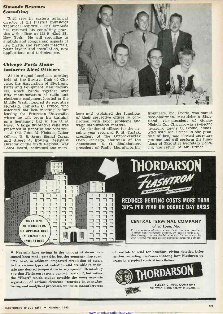
Simonds Resumes Consulting
Until recently eastern technical director of the Plastics Industries Technical Institute, J. Earl Simonds has resumed his consulting prac- tice with offices at 122 E. 42nd St., New York. He will specialize in analysis and commercial aspects of new plastic and resinous materials, plant layout and installation, new applications and technics, etc.
Chicago Parts Manu- facturers Elect Officers
At its August luncheon meeting held at the Electric Club of Chi- cago, the Association of Electronic Parts and Equipment Manufactur- ers, which bands together over fifty manufacturers of radio and electronic equipment located in the Middle West, honored its executive secretary, Kenneth C. Prince, who attended his last meeting before leaving for Princeton University, where he will begin his training as a lieutenant (jg) in the U. S. Navy. A large decorative cake was presented in honor of the occasion.
Lt. Col. John M. Niehaus, Labor Officer, U. S. Army Signal Corps, and Albert A. Epstein, Assistant Director of the Sixth Regional War Labor Board, addressed the mem-
bers and explained the functions of their respective offices in con- nection with labor problems and wage stabilization matters.
An election of officers for the en- suing year returned P. H. Tartak, president of the Oxford-Tartak Corp., Chicago, chairman of the Association. E. G. Shalkhauser, president of Radio Manufacturing
Engineers, Inc., Peoria, was named vice-chairman. Miss Helen A. Stan- iland, vice-president of Quam- Nichols Co., Chicago, was re-elected treasury. Lewis G. Grobe, associ- ated with Mr. Prince in the prac- tice of law, was elected secretary pro tern and will perform the func- tions of Executive Secretary pend- ing the return of Mr. Prince.
ONLY ONE
OF HUNDREDS
OF APPLICATIONS
IN DOZENS OF
INDUSTRIES
THORDARSON
Ä,epH C7 1Jyf NfAR/Of M06R,YEtE7R0.WeCOA'7Rgt
-1 -1 -1 -1
-1 1 -1 -1
-1 -1 -1 1 -11 -1 -1
REDUCES HEATING COSTS MORE THAN
30% PER YEAR ON DEGREE DAY BASIS 1 1 1 1 -1 -1 -1 1 1 1 1
1 1 1 -1 1 1
1 1 1 CENTRAL TERMINAL COMPANY
of St. Louis, Mo. 1 -1 Ì -1
1 -1
1 -1
Proves savings effected s rice Flashtron was installed in steam heating control system, by records made avail-
-1 able through meters double checked for accuracy, by both themselves and utility company supplying steam. 1 1 1
Not only have savings in the amount of steam con- sumed been made possible, but the company also says: "We have, in addition, improved circulation of steam to the various types of radiation and are able to main- tain any desired temperature in any space." Reminding you that Flashtron is not a control "system", but rather the "Heart" which makes possible the more accurate regulation of various elements occurring in manufac- turing and analytical processes, we invite manufacturers
of controls to send for brochure giving detailed infor- mation including diagrams showing how Flashtron op- erates in a typical control installation.
ELECTRIC MFG. COMPANY 500 WEST HURON STREET, CHICAGO, ILL.
ELECTRONIC INDUSTRIES October, 1943 227
www.americanradiohistory.com
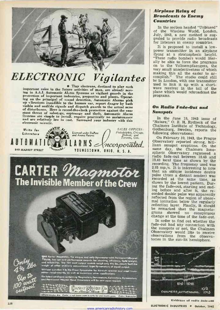
ELECTRONIC Vigilantes
Write for iterafuee
AIITRMATI2 849 MARKET STREET
Tiny electrons, destined to play such important roles in the future activities of man, are already serv- ing in A.A.I. Automatic Alarm Systems as vigilant guards in the protection of important industries, properties and plants. Operat- ing on the principal of sound detection, Automatic Alarms pack up vibrations inaudible to the human ear, report danger by both visibe and audible signals and dispatch guards to the actual zone of disturbance. Here is round-the-clock protection against the con- stant threat of sabotage, espionage and theft. Automatic Alarm Systems are simple to install, require practically no maintenance and are relatively low in cost. Surround your industry with this electronic miracle.
+1.1IC t ^ SALES OFFICES: Philadelphia, Chicago,
Detroit, and Toronto, Can.
ALARMS IW, 0 YOUNGSTOWN. OHIO. U. S. A.
Licensed under DuPont se and Asiatic Patents to
CARTER G~Dot The Invisible Member of the Crew
0(Ate-
E Mºgoolor, the unique and. only Dynamotor with Permanertittagnet fields, has set mew performance records for stamina, efficiency, light weight, and reliability. The 100 watt output models weigh only 4s/.t lbs.,nearl+trait the weigh- of other ordinary conventional type Dynamotor of equal output.
Without question it is the finest Dynamotor for Aircraft receiver and sets it trans. miter requireneits, as well as numerous other applications. The fattest catalogse containing Magmotors, Genemetors, Converters, Dynamotor, and Permanent Magnet Hand Generators win be sent upon request. S 'i-.3...a"<-y"L_.,-r.'-a-
eirne2 L[ l04©ï3 (©e'
1606M/red» Mr. Caeler, o well known name In rade foe on, twenty year,.
Airplane Relay of Broadcasts to Enemy Countries
In the section headed "Unbiased" of the Wireless World, London, July, 1943, a new method is sug- gested to provide radio broadcasts for listeners in enemy countries.
It is proposed to install a low - power transmitter in an airplane flying at a stratospheric height. "These radio bombers would liter- ally be able to force the programs on to the Volksempfaengers, the very small unselectiveness of which making this all the easier to ac- complish." The studio could still be in London, with one transmitter used to link it up with a short- wave receiver in the tail of the plane which would rebroadcast the programs.
On Radio Fade -Out and Sunspots
In the June 19, 1943 issue of "Nature," O. E. H. Rydbeck of the Chalmers Institute of Technology, Gothenburg, Sweden, reports the following observations:
On February 10, 1943, the Prague Observatory reported strong, bril- liant sunspot eruptions. On the same day, the Chalmers Iono- spheric Observatory registered a radio fade-out between 10.43 and 10.48 local time as shown by the recording. The frequency used was 2.93 mp./s. It is interesting to note that an oblique incidence double pulse (from a distant sender) was recorded at the same time, as shown by the lowest pattern. Dur- ing the fade-out, starting and end- ing before and after it, the re- corded double pulse was apparently reflected from the region of abnor- mal ionization below the regularly reflecting layer. Finally, it should be remarked that the magneto - grams showed no conspicuous change at the time of the fade-out.
In order to find out whether the fade-out had any connection with the sunspots or not, the Chalmers Observatory would like to receive observations from the observa- tories in the sun -lit hemisphere.
228 Evidence of radio fade-out
ELECTRONIC INDUSTRIES October, 1943 www.americanradiohistory.com
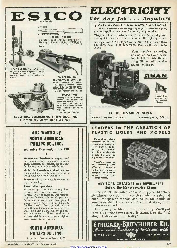
E S,J,, CO r
SOLDERING IRONS are widely used in industrial plants throughout the country. They are designed to withstand the strain of continuous service required of factory tools.
SPOT SOLDERING MACHINE designed for treadle operation for ad- vancement of iron and solder, leaving operator's hands free for handling of product.
tsicOf'y;,,®
/ . hpptlh./. :.. - IIIIIIIIIIII
SOLDERING IRON TEMPERATURE CONTROLS prevent overheating of soldering irons between soldering opera- tions. Irons do not deteriorate when being used. The idle period causes oxidation and shortens life.
SOLDER POTS ruggedly constructed pots of various sizes designed for continuous operation and so constructed that they are easily and quickly serviced, should elements have to be replaced.
Write for Catalog
ELECTRIC SOLDERING IRON CO., INC. 2110 WEST ELM STREET, DEEP RIVER, CONN.
Also Wanted by
NORTH AMERICAN
PHILIPS CO., INC.
see advertisement. page 130
Mechanical Draftsmen experienced in chassis layout, component design, small electrical assemblies, particularly for factory production techniques.
Model Maker-Mechanical, on ex- perimental sheet metal and lathe work for special electronic techniques. Foremen with experience in stem mak- ing and sealing.
Glass lathe operators. Positions open are with young, fast- growing company specializing in elec- tronics. Now engaged in war produc- tion but having substantial post-war future and a world wide background of electronic research and development. Replies should give age and full in- formation on technical training, experi- ence, draft status, availability and sal- ary requirements. If now working in an essential industry at your highest skill, please do not apply.
NORTH AMERICAN
PHILIPS CO., INC. Dobbs Ferry, Westchester County, N. Y.
ELECTRICI4'Y For Any Job . . . Anywhere
* ONAN GASOLINE DRIVEN ELECTRIC GENERATING PLANTS provide electricity for many electronics jobs,
general applications, and for emergency service. They're doing war winning work furnishing vital power and light for scores of war tasks on all the fighting fronts. Ratings from 350 to 35,000 watts. 50 to 800 cycles, 110 to 660 volts, A.C.-6 to 4000 volts, D.C. Also A.C.-D.C. types.
Your inquiry regarding present or post-war needs for ONAN Electric Gener- ating Plants will receive prompt attention.
Awarded to personnel of all four Onan
factories
1
D. W. ONAN & SONS 1895 Royalston Ave. Minneapolis, Minn.
LEADERS IN THE CREATION OF PLASTIC MOLDS AND MODELS
Many of our clients comment on our ex- traordinary ability to follow their needs ex- actly; to produce molds or moldable models that can't be duplicated elsewhere.
There's a reason for this leadership. We offer our clients a
skilled staff to aid in designing injection compression and transfer molds.
ADVISORS, CREATORS and DEVELOPERS Before the Manufacturing Stage
The model illustrated above is a typical Stricker- Brunhuber creation ... consider what a sales aid such transparent models can be in the hands of your sales staff. Here is visual demonstration, in the modern manner !
Bring us your idea or rough drawing. We'll put it in blue print form; carry it through to the final stage. Call or write ... today!
STRICYER"BRiINHIIBER C 0. Oeueu ojd a,nd./1l die4
19 W 24+h.STREET e-8 NEW YORK, N.Y.
WATKINS 9- 0191 - 2 - 3 '
ELECTRONIC INDUSTRIES October, 1943 229
www.americanradiohistory.com
You can hit the high point in
iron core performance
With
G. A.W. CAB i , N Y L
IRON POWDER
Available in three types
High effective permeability
Highest Q value
Other G.A.W. powders being
developed
G. A. W. Carbonyl Iron Pow- der is vital to the leading man- ufacturers of iron cores who supply the carrier and high frequency fields and must have the highest attainable effi- ciency.
We will be glad to furnish fur- ther information and will ap- preciate knowing your require- ments. Address :
GENERAL ANILINE WORKS A DIVISION OF
General Aniline and Film Corp. 435 Hudson St. New York, N. Y. Manufacturers e Sole Distributors
ELECTRONIC TOMORROWS: When Electronic Cooking Will Do in Minutes, What Now Takes Hours-
Imagine putting your roast in the oven as you sit down to dinner . .
and finding it ready to serve by the time you've finished your soup! Yet scientists predict such speed, economy and convenience are only a few of the many benefits electronic cooking can bring to postwar homes.
Because this method generates heat from the inside at the same rate as from the outside, food can be cooked through-with no danger of burning, no wasteful shrinkage, no loss of val- uable juices. Weight and thickness make no difference, either ... 100 lb. can be cooked as fast as 1 lb. And since the heat is concentrated in the food, utensils stay comparatively cool -hands are not burned.
Delco Appliance salutes the scien- tists whose electronic applications promise so much for future home life. Our own use of electronics is now con- fined to war production, because "Vic- tory is Our Business" . . . but with peace, it will help us build new and finer Delco Appliances for your home. -Saturday Evening Post advertise- ment by Delco Appliance.
MILESTONES TOWARD THE ELECTRONIC ERA The First Cathode Ray Tube?
What may well be a description of the first cathode ray tube appeared in print some 93 years ago in connec- tion with the details of an experiment that was set up to prove the hypoth- esis of the aurora borealis. Many years later much further work along these lines was done by Stormer using very low speed cathode rays, and at that time, heated cathodes. Incidentally, many readers may not be aware of the similarities between the northern lights and the cathode rays of the television tube, so this glance backward nearly a century may be of interest:
Influence of magnetism "A memoir by Morlet on the aurora
borealis induced M. de la Rive to com- municate to the Paris Academy the following experiment, showing the in- fluence of magnetism on the light pro- duced by ordinary electrical dis- charges. `I introduce into a glass globe, by one of the two tubulures with which it is furnished, a cylin- drical iron bar, of such length that one of its extremities reaches nearly to the centre of the globe, while the
PLUGS AND SOCKETS
Three series of Plugs and Sockets !¡y
Y cover practically every requirement:
300 series, a popular line of Irl small plugs and sockets adaptable
P3a4ccT to a thousand uses-from 2 to 23 contacts;
400 series of heavier construc- tion for the Radio, Public Address
s3o4Ya and kindred fields - made in 2, 4, 6, 8, 10 and 12 contacts;
500 series, heavy duty plugs and sockets designed for 5000 volts and 25 amperes- made in 2, 4, 6, 8, 10 and 12 contacts. All sizes are polarized. All plug contacts are of brass. All socket contacts are of phosphor bronze - Molded, Bakelite Bodies - TOP quality throughout.
TERMINAL STRIPS For Every Requirement
ranging from small sizes (5-40 screws) to large sizes (10 - 12 screws). Over 500 standard items. Also mounted on panels to your specifications.
Illustration shows new Barrier Strips, sup- plied in six sizes from 3/4" wide and 13/32" high to 21/2" wide and 11/s" high. Barriers provide long leakage paths and prevent shorts from frayed wires at terminals.
Send for a copy of No. 13 catalog
HOWARD B. JONES 2460 WEST GEORGE STREET
CHICAGO 18, ILLINOIS
ENGINEERING OPENING
PROJECT SUPERVISOR Permanent position with an established Connecticut con- cern manufacturing communi- cations equipment.
Prefer top-notch man with uhf experience w ho c an take charge of development or de- sign project.
Salary commensurate with ability.
Additional compensation for assignment of patents.
Pleasant working conditions.
Those now employed in essen- tial activity must be able to obtain a release.
ADDRESS:
DALE POLLACK Chief Engineer
TEMPLETONE RADIO CO. MYSTIC CONNECTICUT
230 ELECTRONIC INDUSTRIES October, 1943 www.americanradiohistory.com
D.C. to A.C. CONVERTERS When only D.C. power is available, A.C. Electronic devices can be operated by using dependable
JANETTE rotary converters. Many thousands are in use on ships, shore stations, as well as for domes- tic applications. Built In the 5 styles Illustrated, for 6 to 230 volts input 1
to 110 and 220 volts, D.C.C input
A.C. output. Ask for phase, cycle
bulletin No. 13-25. Dynamotors are also available.
Wherever there are ships, you will find Janette converters.
Janette, Manufacturing ,556-558V. lYl.onroe Si. ehicaiia, IU,.
ELECTRON TUBE MACHINERY of every type, - standard, and special design
EncInEERInc company Specialists in EQUIPMENT and METHODS for the Manufacture of Radio Tubes, Cathode Ray Tubes, Fluorescent Lamps, Incandescent Lamps, Neon Tubes, Photo Cells, X -Ray Tubes and other glass or electronic products, on production or laboratory basis.
1307-1309 Seventh St., North Bergen, N. J.
Manufacturer's Representative, 42, 3AN, covering Wisconsin, Upper Michigan, Minnesota and North and South Dakota with lines of industrial paging, inter -corn systems and electronic devices for indus- trial use, now desires one or two additional lines of top quality equipment. Able to handle thru jobbers and dealers or direct. Record of accomplishment will stand strictest investigation.
Write Electronic Industries Box No. 47R.
EISLER
TUBE
SEALING MACHINE
1 pop ̀ i When production is so vital
and important-let EISLER equipment help you speed up your essential orders.
Our engineers are available to study and make recom- mendations for your particular problems.
Our 25 years of experience is your best guarantee.
*WRITE ToPAyI Chas. Eisler's new 94 page most
complete catalog for general glass working and electronic equipment.
CHAS. EISLER EISLER ENGINEERING CO. 778.SO. 13th ST. Neer AVON AVE. NEWARK.3 N. J.
s° 111111111
21.e PLASTIC SAVE METAL-
IMPROVE PRODUCT Saving millions of tons of war -vital metal for Victory ... That's the immensely important part PLASTIC is playing in helping to win the war. And in most cases plastic results in better looking, more satisfactory products when properly engineered. Illustrated above is an inspection flash light ... one of the innumerable items on which STANDARD Plastics have either entirely or par- tially replaced metal. Have you considered the possibility of in- creasing production in your plant with plastics? We gladly offer you the benefit of our knowledge and experience. Write us today.
STANDARD MOLDING CORPORATION, Dayton, Ohio /00% INJECTION MOLDING
ELECTRONIC INDUSTRIES October, 1943 231
www.americanradiohistory.com
REFLEX SPEAKERS
now the accepted
STANDARD for all
WAR USE
EVERY UNIVERSITY REFLEX the result of years of pioneering research and development.
EVERY HIGH EFFICIENCY
SPEAKER in University's extensive line of power speech re- producers has a vital part to play in the WAR program.
REMEMBER University is now pro- ducing many special speakers for the Army, Navy & Signal Corps. Submit your special problem direct to the engineering dept.
UNIVERSITY LABS., 225 VARICK ST., NYC
.011 - puidid ed
EXPERIMENTS IN ELECTRONICS and
COMMUNICATION ENGINEERING
liV6RIY>rTº
in Iati>CTROSIC9 and
CONaVaICATIOa ffir6IN51ZRI9a
A unique and practical labora- tory guide for work in basic cir- cuit theory, electronics, com- munication networks, radio, and ultra -high -frequency techniques. Developed for the Electronics
j and Ultra -High -Frequencies Training Schools of the Signal Corps of the U.S. Army. 108 experiments included.
HARPER & BROTHERS 49 E. 33rd St., New York 16, N. Y.
Please send me EXPERIMENTS IN ELECTRONICS and COMMUNICATION ENGINEERING. I en-
close $3.00.
Name
Address
other extends a short distance out of the tubulure. The bar is hermetically sealed in the tubulure, and covered throughout its length, except at its two ends, with an isolating and thick layer of wax. A copper ring surrounds the bar above the isolating surface in its internal part the nearest to the side of the globe; from this ring pro- ceeds a conducting rod, which, care- fully isolated, traverses the same tu- bulure as the iron bar, but without communicating with it, and terminates externally in a knob.
"'When, by means of a stopcock ad- justed to the second tubulure of the globe, the air in it is rarefied, the knob is made to communicate with one of the conductors of an electric machine, and the external extremity of the iron bar with the other, so that the two electricities unite in the interior of the globe, forming between the internal extremity of the iron bar and the cop- per ring which is at its base a more or less regular fascicle of light. But if the external extremity of the iron bar is placed in contact with one of the poles of a strong electro -magnet, taking good care to preserve the iso- lation, the electric light takes a very different aspect.
Electrical egg
"'Instead of issuing, as before, from the different points of the sur- face of the terminal part of the iron bar, it is emitted only from the points which form the contour of this part, so as to constitute a continuous lumi, nous ring. This is not all; this ring and the luminous jets which emanate from it have a continuous movement of rotation around the magnetized bar, now in one direction, now in an- other, according to the electric dis- charges and the direction of the mag- netization. Lastly, more brilliant jets appear to issue from this luminous circumference, without being con- founded with those which terminate on the ring and from the fascicle. As soon as the magnetization ceases, the luminous phenomena becomes again what it was previously, and what it is generally in the experiment known as the electrical egg.'
"This experiment appears to account very satisfactorily for what passes in the phenomena of the aurora borealis; in fact, the light which results from the union of the two electricities in the part of the atmosphere which covers the polar regions, instead of remaining vaguely distributed, is car- ried by the action of the terrestrial magnetism round the magnetic pole of the globe, whence it seems to rise in a revolving column, of which it is the
Plailic NAME PLATES
EMPLOYEE IDENTIFICATION
BADGES
DIALS -CHARTS DIAL COVERS
SCALES -RULES SCHEMATICS
GRAPHS USED BY
ARMY, NAVY, AIR CORPS
Printers & Fabricators of PLASTIC SHEETING
OUR 46TH YEAR
PARISIAN NOVELTY CO. 3516-26 SO. WESTERN AVE.- CHICAGO
IF YOU want to"let your- self go," in a new and revolutionary elec- tronic field
IF YOU are right at home in UHF and Television.
IF YOUR present work cramps your style, in- genuity or opportunity and if your full talents are not 100% for war
THEN
COME WITH US We are carrying the ball in a scientific battle against the en- emy. We need compe- tent research engi- neers. Outline your education, experience, marital status and sal- ary requirements. Address:
PANORAMIC RADIO CORP. 245 W. 55TH ST. NEW YORK 19, N. Y.
232 ELECTRONIC INDUSTRIES October, 1943 www.americanradiohistory.com
eh -4r B EFORE D URING AFTER
BEFORE the war SNYDER products satisfied the nation's peacetime Antennae require- ments for more than a decade. DURING these war years, use has demonstrated the correct- ness of design and operation of their products. Their record of accurate and dependable per- formance is the basis of their war -wide acceptance. AFTER the war is won post- war plans include SNYDER's continued leadership in the field.
ANTENNAE & ASSOCIATED PRODUCTS
,h
We are prepared to supply etched metal
DIALS PANELS
PLATES
made to your precise engineering specifi- cations in all metals and finishes.
THIRTY YEARS OF SERVICE
TO AMERICAN INDUSTRY
*
PREMIER METAL ETCHING CO.
21-03 44TH AVENUE
LONG ISLAND CITY, NEW YORK
base. We thus understand why the magnetic pole is always the apparent center whence issues the light consti- tuting the aurora borealis, or towards which it appears to converge."-Silli- man's Journal, May, 1850.
Some Radio and Light Analogies By David Grimes Vice-president Philco, Inc.
The untimely death of Dave Grimes in an airplane crash overseas is re- ported on page 204 of this issue. Earlier/ in the summer, Mr. Grimes had given the following delightful discussion of radio principles before the N. Y. In- stitute of Finance, injecting character- istically some new relationships and angles which most radio men may have overlooked.
Light is an electro -magnetic wave. There is no difference be- tween the light you see with your eye, coming out of these lamps, and the radio wave which brings you your program from the local broadcasting station. I say "no difference whatever," that is, outside of the fact that the waves coming to you from the broadcasting sta- tion are created by electrons that vibrate slowly in the antenna, so that the waves are long waves, while the waves coming to you from an atom (light waves) are short waves-very, very short!
When we want to pick up one of these electro -magnetic waves that have been generated by whatever source, we try to select an antenna of the same comparable dimensions as the antenna where the original wave was created. We call that res- onance. You have similar reso- nance in a piano or any musical instrument. If you put your foot on the loud pedal of a piano and sing into the piano, whatever note you sing, the piano will respond back to you. Put your foot on the loud pedal, take the felts away from the strings, and sing into the piano, and whatever note you sing, the string for that note will be set into vibration by your own vocal chords, and the string will answer you back.
Short paths, high frequency
So when we are receiving any wave and want the electrons to be set up in our receiving apparatus so that they will start vibrating of their own free will, we choose an antenna of about the same length
We'll make it for you!
-or help you make it Plant facilities and
trained technicians of
RADIO WIRE TELEVISION INC. now available for manufacturing Electronic and associated products.
We have been making: Pre -amplifiers Power supplies Rectifier Units Cord Sets We have done much work involving Chassis Wiring Assembling Soldering etc. We can handle all kinds of Sub -Assembly Work.
Among our Customers: U. S. Army Signal Corps Large Industrial Concerns
Examine our Credentials: ONE OF THE OLDEST and largest radio supply houses in the world. 22 years experience in this field.
WE HAVE MADE Public Address and Sound Equipment for the past ten years.
WE HAVE PIONEERED several new
audio developments.
COMPETENT ENGINEERING STAFF,
expert purchasing and expediting departments.
KNOWN TO ALL MANUFACTURERS in the field-to many as far back as 1921-and therefore in position to demand and get preferential treatment.
NO LABOR SHORTAGE. Plant faci- lities in New York area.
3 PRIVATE TELEPHONE LINES reserved exclusively for personal and efficient service to industrial customers.
INQUIRIES INVITED CONSULT US WITHOUT OBLIGATION
Aio hire 7/,pisürn Inc.
100 SIXTH AVENUE, NEW YORK
BOSTON, MASS. NEWARK, N. 1.
o
NEED RADIO PARTS? If "se carry large stocks of radio and electronic parts at all times. 11'é
distribute the products of all nationally -known manufacturers o f radio and electronic equipment. Immediate shipment on anything in stock-no need to split orders. Naturally, items restricted by WPB are held for government sale only. FREE: catalogs, supplements and bargain flyers which we publish from time to time will he mailed to you without charge, on request.
ELECTRONIC INDUSTRIES October, 1943 233 www.americanradiohistory.com
For Tomorrow's Broadcasting-
LOOK TO
*LINGO For advanced design and
superior performance in
VERTICAL TUBULAR
STEEL RADIATORS
PATENTED FM
TURNSTILE RADIATORS
We're "all out" for Vic-
tory. but our engineers
are ready to work with
you on post-war plans.
JOHN E. LINGO & SON, Int.
CAMDEN. NEW JERSEY
25 YEARS EXPERIENCE
in our business means:-
"KNOW-HOW" We specialize in building automat- ically operated machines where close tolerances and fine work- manship are required, to special design for the largest manufactur- ers in this country.
We will gladly cooperate with your engineers in the develop- ment of new machinery, as well as the necessary rebuilding of older equipment.
Send in your drawings for estimates
* * * DALY MACHINE & TOOL WORKS
923 FRELINGHUYSEN AVE. NEWARK. N. J.
Bigelow 3-0234 and 0235
as the transmitting antenna; we set up the circuits so they are about the same length electrically. Thus, when we get up to ultra high frequencies, our receiving antenna is short because the transmitting antenna is short, the electrons are vibrating rapidly in a short dis- tance, and the electrons of the re- ceiver are sped up in resonance.
I would like to speculate, for a moment, as to what our mechanism of vision comprises. In the com- plex structure of the rods and cones in the back of your eyes you have atomic resonance circuits of some sort-or atomic resonance- so that these ultra micro micro waves (light) coming from the electrons within the atoms, set up the vibration of the electrons with- in your eye structure, creating a sensation of light.
Great big eyes! Now, we might travel from that
to visualize, for a moment, what would happen if our eyes were big- ger. Suppose our eyes were so large that the rods and cones could resonate to the broadcast fre- quency. I wouldn't want to say how big those eyes would be, but suppose, for a moment, in order to draw on our imaginations, we had eyes big enough to see the broad- cast frequencies, the waves sent out from the broadcast stations. Then each and every one of these broad- cast stations would appear to be a huge lighthouse. WJZ would send out, up and down, these waves of light. You would see that light. It would have a distinctive color. I don't know what color it would be, because I have never "seen" those colors.
Those waves would go out, and no matter how far away you went, the station would be that same color. If WJZ should be "blue" at the transmitter, it would be blue a hundred miles away; and of course, after you got beyond the line of sight, or the horizon, you would see WJZ as a blue reflection in the sky, much like you see the sunset long after the sun has gone down beyond the horizon; you would see the light reflected on the clouds or the lighter layers of air.
Bye, bye, Wall Street! If you looked around here in
Wall Street with those big eyes just mentioned, you wouldn't see any people. For people would all be transparent; the buildings, too, would be very largely transparent, as if they were built of glass brick.
N E IRI Test Lead
This new ICA Test Lead (No. 373) is approved by the Signal Corps. Pre- ferred by lead- ing test equip- ment manu- faeturers. Mfrs. and Corn - tractors, write for this 12 - page Indus- trial Catalog.
InsuunE CORPORATION OF AMERICA
INSULINE BUILDING (36-02 35th AVENUE)
LONG ISLAND CITY, N.Y.
1
BIRD & CO.
GLASS
ISTI1E1UEff
BEA1LRGS GLASS "V" BEARINGS
made to your specifications
We welcome your inquiries
RICHARD II. BIRD Manufacturer of Jewel Bearings
for thirty years
23 MOODY STREET
WALTHAM, MASS.
234 ELECTRONIC INDUSTRIES October, 1943 www.americanradiohistory.com
.,<a x e", ,,.nt7En - t .,'L,....,"'"
NAME PLATES SCALES, GAUGES,
CALCULATORS, CHARTS, DIALS, ETC.
SPAULDING`/M05S Co.
wvvv oX, NA55.
F 17 FRANKLIN ST F
Impervious to moisture, grease, oils, acids, alkalis.
Printing guaranteed not to wash or rub off. Non -inflammable, non -corrosive plastic. Printed and laminated vinylite and cellulose acetate.
SAMPLES AND ESTIMATES GLADLY SUPPLIED ON REQUEST WRITE DEPARTMENT
THE HOPP PRESS, INC. PRINTING - FABRICATING - FORMING
460 W. 34th STREET, N. Y. C. ESTABLISHED 1883
CONDENSERS- Electrolytic Mica Oil Variable HARRISON has
258,051
RESISTORS- Carbon Wire -wound Rheostats Controls HARRISON has
52,718
FREE! 800 -Page BUYER'S GUIDE
Kindly write on Com- pany letterhead, giving
title
TRANSFORMERS- Audio Power Reactors HARRISON has
2,763
TUBES- I ndustrial Receiving Transmitting HARRISON has
28,612
O tli er" Electronic supplies-
HARRISON lias plenty! FOR IMMEDIATE
DELIVERY!
Our complete stock, speedy
service, procurement experi- ence, and technical knowl- edge make us the logical source for ALL your Elec- tronic Parts and Equipment
requirements.
Give us your orders-large and small. We can "deliver the goods"-sooner!
Phone WOrfh 2-6276 ESTABLISHED 1925
Authorized Distributors for All Leading Manufacturers
HARRISON RADIO CORPORATION
12 WEST BROADWAY NEW YORK 7
But the steel ribs in the buildings, all the steel work, would stand out opaque, because steel is impervious to these long waves, broadcast waves. You might wonder. It might be hard for you to under- stand how these broadcast waves can go right through a wooden or plastic wall, and yet you can't put your fist through the wall. But it is no more. wonderful than that light can go through the glass win- dows because of the structure of the molecules within the glass, and yet you can't put your fist through it very readily.
Then, as you looked around, (still with your big eyes), you would see automobiles going up and down the street, traveling maybe four or five inches above the trans- lucent pavement, because you wouldn't see any rubber-(and you won't see any rubber, anyway, in another year or two). You wouldn't see it with these radio eyes of yours.
I think we are probably ready now to discuss philosophically how AM operates, and then discuss philosophically what FM is in the picture I have just painted. I am going into no circuits, no details.
If this WJZ broadcasting station had a program on it, and your eyes were tuned to the broadcast band, big ones, and your eyes were quick enough, you would see a flicker oc- curring on this beam of blue light that I referred to as WJZ. The flickers would be the program emanating from the broadcast studio. Flickers would appear on the program sent out by the an- nouncer or by the piccolo player or by anybody who happened to be in front of the microphone. It would be a flicker in the blue light, from very intense blue to very dim blue, but it would be the same shade of blue.
FM is essentially a system of modulation whereby, instead of the light being increased and decreased in intensity as you put the program on the air, the color of the light beam is changed.
You still have these broadcast eyes, now, so to speak; you are still seeing these beams of light; you are still seeing these radiations, for the moment, and so the color of an FM station, the color of its beam would change as the program was put on in the studio. The color would switch back and forth, from light blue to deep blue, or from cobalt blue to deep blue. That is it would shift back and forth in color but not in brilliance or intensity.
GOULD MOODY CAN GIVE YOU THE RECORDING BLANKS
YOU REQUIRE
GLASS BASE INSTANTANEOUS
RECORDING BLANKS
Don't delay ordering your "Black Seal" Record- ing Blanks because of priorities. An AA -2X rating is automatically available to all broadcasting stations, recording studios and schools.
"No better instantaneous reccrding blank was
ever made," say engineers in major broadcast-
ing stations from coast -to -coast of the new
Gould -Moody "Black Seal" Glass Base Install. taneous Recording Blanks.
Enclosing your priority rating when ordering
will expedite deliveries.
THE GOULD -MOODY COMPANY
RECORDING BLANK DIVISION
395 BROADWAY NEW YORK 13, N.Y.
ELECTRONIC INDUSTRIES October, 1943 235
www.americanradiohistory.com
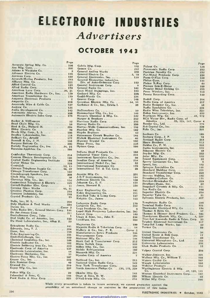
ELECTRONIC INDUSTRIES Advertisers OCTOBER 1943
Page Accurate Spring Mfg. Co. 198 Ace Mfg. Corp. 202 Adams & Westlake Co. Advance Electric Co. 195 Aerovox Corp. 168 Aircraft -Marine Products, Inc. 215 Alliance Mfg. Co. 221 Allied Control Co. 125 Allied Radio Corp. 178 American Lava Corp. 20, 21 American Radio Hardware Co., Inc. ... 129 American Transformer Co. 119 Amperex Electronic Products 2 Amperite Co. 208 Anaconda Wire & Cable Co. 127 Andrew Co. 126 Audio Development Co. 142 Automatic Alarms, Inc. 228 Automatic Electric Sales Corp. 175
Barker & Williamson 32 Bead Chain Mfg. Co. 16 Bird & Co., Richard H. 234 Bliley Electric Co. 30 Brach Mfg. Corp., L. S. 186 Bradley Laboratories, Inc. 118 Brilhart Co., Arnold 177 Bunnell & Co J. H. 155 Burgess Battery Co. 200 Burndy Engineering Co., Inc. 24, 25 Burstein-Applebee Co. 184
Cambridge Thermionic Corp. 214 Cannon Electric Development Co. 122 Capitol Radio Engineering Institute 184 Carter Motor Co. 228 Centrelab 12, 13 Chicago Telephone Supply Co. 36, 37 Chicago Transformer Corp. 160 Cinaudagraph Speakers, Inc. 208 Cinch Mf g. Corp. 38 Clarostat Mfg. Co., Inc. 116 Connecticut Telephone & Electric 225 Cornell-Dubilier Elec. Corp. 11 Corning Glass Works 50, 51 Creative Plastics Corp. 218 Crescent Industries, Inc. 218 Crystal Products Co. 53
Delis, Inc., H. L. 204 Daly Machine & Tool Works 234 Doyen Co. Cover 3 Delco Radio Div., General Motors Corp.. 191 De Jur-Amsco Corp. 211 Deutschmann Corp., Tobe 1 Dial Light Co. of America, Inc. 223 Du Mont Laboratories, Inc., Allen B 27 Echophone Radio Co. 181 Edwards, Inc., T. J. 204 Eicor, Inc. 158 Eisler Engineering Co. 231 Eitel -McCullough, Inc. 209 Electrical Insulation Co., Inc. 188 Electric Indicator Co. 182 Electric Soldering Iron Co., Inc. 229 Electronic Corp. of America 137 Electronic Laboratories, Inc. 44 Electronic Mechanics, Inc. 33 Electro -Voice Mf g. Co., Inc. 187 Eraser Co., Inc. 225 Erie Resistor Corp. 40 Erwood Co. 210 Espey Mfg. Co., Inc. 220
Felker Mfg. Co. 29 Felsenthal & Sons, G. 196 Ford Radio & Mica Corp. 225
Page Galvin Mfg. Corp. 135 Gemex Co. 212
3 General Aniline Works 230 General Electric Co. 5, 19 General Electronics, Inc. 139 General Electronics Industries,
Div. of Auto -Ordnance Corp. 153 General Instrument Corp. 9 General Radio Co. 162 Goat Metal Stampings, Inc. 189 Gothard Mfg. Co. 220. Gould -Moody Co. 235 Groves Corp. 148 Guardian Electric Mf g. Co. 54, 55 Guthman & Co.. Inc., Edwin I. 35
Hallicrafters Co. 39 Hammarlund Mf g. Co., Inc. 165 Hanovia Chemical & Mf g. Co. 222 Harper & Brothers 232 Harrison Radio Corp. 235 Harvey Radio Co. 150 Harvey -Wells Communications, Inc. 156 Haydon Mfg. Co. 182 Haydu Brothers 43 Heinemann Circuit Breaker Co. 144 Hickok Electrical Instrument Co. 46 Hipower Crystal Co. 192 Hopp Press, Inc. 235 Hytron Corp. 109
Indiana Steel Products Co. 183 Industrial Timer Corp. 224 Instrument Specialties Co., Inc. 56 Insuline Corp. of America 234 International Nickel Co., Inc. 52 International Resistance Co. 179 International Tel. & Tel. Corp. 28
Janette Mfg. Co. 231 J -B -T Instruments, Inc. 164 Jefferson Electric Co. 168 Johnson Co., E. F. 131 Jones, Howard B. 230
Kaar Engineering Co. 161 Kahle Engineering Co. 231 Ken -Rad Tube & Lamp Corp. 197 Knights Co., James 143
Lafayette Radio Corp. 170 Langevin Co., Inc. 219 Lapp Insulator Co., Inc. 6 Lepel High Frequency Laboratories, Inc 202 Lewyt Corp. 180 Lingo & Sons, Inc., John E. 234 Littelfuse, Inc. 200
Magnavox Co. 199 Majestic Radio & Television Corp. 14 Mallory & Co., Inc., P. R. Cover 2 Manufacturers Screw Products 166 Measurements Corp. 184 Meissner Mfg. Co. 194 Merit Coil & Transformer Corp. 212 Micro Switch Corp. 205 Millen Mfg. Co., Inc. 132 Mobile Refrigeration 192 Monarch Mfg. Co. 224 Mycalex Corp. of America 7
National Co., Inc. 213 National Union Radio Corp. 149 New York Transformer Corp. 163 North American Philips Co. ..130, 173, 229
Ohmite Mfg. Co. 145 Onan & Sons, D. W. 229 O'Neil -Irwin Mfg. Co. 216
Page Palnut Co. 128 Panoramic Radio Corp. 232 Parisian Novelty Co. 232 Par -Metal Products Corp. 226 Perm -O -Flux Corp. 138 Philco Corp. 141 Picker X -Ray Corp. 49 Pioneer Gen -E -Motor 188 Premier Metal Etching Co. 233 Press Wireless, Inc. 115 Presto Recording Corp. 140
Radell Corp. 216 Radio Corp. of America 217 Radio Receptor Co., Inc. 58 Radio Specialties Co. y21 Radio Wire Television, Inc. 233 Rahm Instruments, Inc. 222 Raytheon Mf g. Co. 41, 172 RCA Victor Div., Radio Corp. of
America 23, 123, 147, Cover 4 Remler Co., Ltd. 174 R-9 Crystal Co., Inc. 226 Rola Co., Inc. 201
Sanborn Co. 185 Seeburg Corp., J. P. 18 Sentinel Radio Corp. 214 Shure Brothers 113 Sickles Co., F. M. 203 Sigma Instruments, Inc. 176 Simpson Electric Co. 48 Snyder Mfg. Co. 233 Solar Mfg. Co. 159 Sound Equipment Corp. 22 Sperry Gyroscope Co., Inc. 8 Sperti, Inc. 152 Sprague Specialties Co. 151 Standard Molding Corp. 231 Standard Transformer Corp. 223 Stevens Walden, Inc. 190 Stromberg -Carlson Co. 171 Stricker-Brunhuber Co. 229 Struthers -Dunn, Inc. 26 Stupakoff Ceramic & Mfg. Co. 111 Sun Radio Co. 166 Superior Electric Co. 210 Superior Tube Co. 31 Sylvania Electric Products, Inc. 207
Templetone Radio Co. 230 Terminal Radio Corp. 221 Thermador Electrical Mf g. Co. 136 Thomas & Betts Co. 57 Thomas & Skinner Steel Products Co 186 Thordarson Electric Mfg. Co. 4, 227 Trav-Ler Karenola Radio & Telev. Corp. 10 Triplett Electrical Instrument Co. 117 Tung -Sol Lamp Works, Inc. ... 42 Turner Co. 59
United Electronics Co. 34 United Screw & Bolt Corp. 17 United Transformer Co. 60 Universal Microphone Co., Ltd. 154 University Laboratories 232 Utah Radio Products Co. 15
Valpey Crystal Corp. 206 Walker-Jimieson, Inc. 221 Wallace Mf g. Co., William T. 146 Waters Conley Co. 167 Waugh Laboratories 193 Webster Products 133 Westinghouse Electric & Mfg.
Co. 47, 120, 121 Weston Electrical Instrument Corp..... 157 Wilcox Electric Co. 45 Willor Mfg. Corp. 206
While every precaution is taken to insure accuracy, we cannot guarantee against the possibility of an occasional change or omission in the preparation of this index.
236 ELECTRONIC INDUSTRIES October, 1943
www.americanradiohistory.com
YOUR DOLLARS ARE NEEDED NOW ... BUY MORE WAR BONDS AND STAMPS
2
1=-
¡Earnrì rrtigr One effective way of judging a product is by the qual-
ity of equipment in which it is incorporated. If it's a
companion piece to the finest in the field, you car be
sure that it, too, has earned its prestige.
In top-ranking motion picture sound recording
studios, where standards are highest, DAVEN products
are preferred. They are the original components in
major fixed installations, and are also specified by studio
engineers whenever special apparatus is developed.
DAVEN produces the most complete line of precision attenuators in the world, plus more than 80 models of laboratory test equipment for the broadcast, sound picture, television and electrical fields. May we send you a catalog?
www.americanradiohistory.com
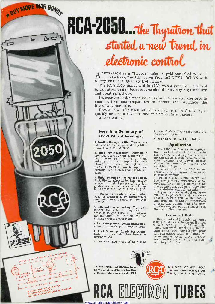
RCA-2050.Ate,t,,anettitiond,
ilectionie ameot
-
ATHYRATRON is a "trigger" tube-a grid -controlled rectifier -which can "switch" power from full OFF to full ON with
a very small change in control voltage. The RCA -2050, announced in 1939, was a great step forward
in thyratron design because it combined unusually high stability and great sensitivity.
Its characteristics were more uniform, too-from one tube to another, from one temperature to another, and throughout the life of any one tube.
Because the RCA -2050 offered such unusual performance, it quickly became a favorite tool of electronics engineers.
And it still is!
Here is a Summary of RCA -2050's Advantages
1. Stability Throughout Life. Character- istics of 2050 change relatively little throughout life of tube. 2. High Power -Sensitivity. Extremely low grid current (less than 0.1 mi- croampere) permits use of high value grid resistor (up to 10 meg- ohms) with consequent high sensi- tivity. RCA -2050 can be operated directly from a high vacuum photo - tube. 3. Little Affected by Line -Voltage Surges. Stability as affected by line voltage surges is high because of the low grid -anode capacitance which re- sults from the use of a shield grid. 4. Extreme Temperature Range. RCA - 2050 is unaffected by temperature changes over the range of -50°C to +65°C!
5. All -position Mounting. You can mount the 2050 in any position since it is gas filled and contains no mercury. Its position can be changed during operation. 6. Low Voltage Drop. Xenon filling pro- vides a tube drop of only 8 volts. 7. Quick Warm-up. Ready for opera- tion in 10 seconds after heater is switched on. 8. Low Cost. List price of RCA -2050
The Magic Brain of All Electronic Equip- ment Is a Tube and the Fountain -Head of Modern Tube Development Is RCA.
RCA 1
is now $1.35, a reduction from its original price. 9. Army -Navy Preferred Type Listing.
Application The 2050 has found wide applica-
tion in industrial control circuits. Its high power -sensitivity has made it invaluable as a link between actu- ating circuits and power circuits eliminating amplifier stages and sensitive relays.
The stability of the 2050 makes possible a high degree of accuracy in timing circuits.
The RCA -2050 is extensively used in control circuits for positioning, for welding, for air-doffer operation, for plastic molding, and as a relay tube in phototube control circuits.
If you have an application prob- lem, RCA application engineers may be able to help you. Write, stating your problem, to Radio Corporation of America, Commercial Engineer- ing Section, 490 South Fifth Street, Harrison, New Jersey.
Technical Data Heater volts, 6.3; heater amperes,
0.6; grid -to -anode capacitance, 0.2uttf; heating time, 10 seconds; maximum overall length, 4t/s inches; base, small shell octal 8 -pin; peak forward anode volts, 650; peak in- verse anode volts, 1300; average anode milliamperes, 100; tube volt- age drop, 8 volts.
TUNE IN "WHAT'S NEW?" RCA's great new show, Saturday nights, 7 to 8, E. W. T., Blue Network.
FIi TUBES
4t
www.americanradiohistory.com
Related Documents