F i b r s a d P r b Fibers and Probes Ocean Optics provides the most flexible line of optical fibers available. We craft our standard and custom fiber assemblies to provide you years of reliable, accurate results. Y ou can depend on Ocean Optics for everything from one-off patch cords and custom assemblies to OEM builds for virtually a ny application you can imagine. Our fiber accessories, fixtures and fiber assembly kits allow you to easily connect or manipulate fibers and integrate them into the most challenging application setups. T o get the most from your Oc ean Optics optical fiber, it’s important to use special care in handling. Never bend or wind fibers tightly and al- ways store in a cool, dry place. Tip

Welcome message from author
This document is posted to help you gain knowledge. Please leave a comment to let me know what you think about it! Share it to your friends and learn new things together.
Transcript

8/14/2019 Ocean_Optics_Fibers_Probes.pdf
http://slidepdf.com/reader/full/oceanopticsfibersprobespdf 1/22
F i b er sand P r ob e
s
Fibers and ProbesOcean Optics provides the most
flexible line of optical fibers available.
We craft our standard and custom
fiber assemblies to provide you years
of reliable, accurate results. You can
depend on Ocean Optics for
everything from one-off patch cords
and custom assemblies to OEM
builds for virtually any applicationyou can imagine.
Our fiber accessories, fixtures and
fiber assembly kits allow you to easily
connect or manipulate fibers and
integrate them into the most
challenging application setups.
To get the most from your Ocean
Optics optical fiber, it’s important to
use special care in handling. Never
bend or wind fibers tightly and al-
ways store in a cool, dry place.
Tip
8/14/2019 Ocean_Optics_Fibers_Probes.pdf
http://slidepdf.com/reader/full/oceanopticsfibersprobespdf 2/22
F
i b e r s a n d P
r o b e s
2 www.oceanoptics.com Tel: +1 727-733-2447
Fibers and ProbesThe Most Flexible Line in the Industry
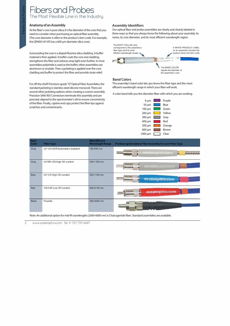
At the fiber’s core is pure silica; it’s the diameter of the core that you
need to consider when purchasing an optical fiber assembly.(The core diameter is often in the product’s item code. For example,
the QP600-UV-VIS has a 600 µm diameter silica core).
Surrounding the core is a doped-fluorine silica cladding. A buffer
material is then applied. A buffer coats the core and cladding ,
strengthens the fiber and reduces stray light even further. In most
assemblies polyimide is used as the buffer; other assemblies use
aluminum or acrylate. Then a jacketing is applied over the core,
cladding and buffer to protect the fiber and provide strain relief.
For off-the-shelf Premium-grade “Q” Optical Fiber Assemblies, the
standard jacketing is stainless steel silicone monocoil. There are
several other jacketing options when creating a custom assembly.
Precision SMA 905 Connectors terminate the assembly and are
precisely aligned to the spectrometer’s slit to ensure concentricityof the fiber. Finally, captive end caps protect the fiber tips against
scratches and contaminants.
Anatomy of an Assembly Assembly Identifiers
A WHITE PRODUCT LABEL
on an assembly includes the
product name and item code.
The BAND COLORsignals the diameter of
the assembly’s core.
The BOOT COLLAR color
corresponds to the assembly’s
fiber type (and its most
efficient wavelength range).
Our optical fiber and probe assemblies are clearly and cleanly labeled in
three ways so that you always know the following about your assembly: itsname, its core diameter, and its most efficient wavelength region.
8 µm50 µm
100 µm
200 µm
300 µm
400 µm
500 µm
600 µm
1000 µm
PurpleBlue
Green
Yellow
Gray
Red
Orange
Brown
Clear
A color band tells you the diameter fiber with which you are working.
Band Colors The assembly’s band color lets you know the fiber type and the most
efficient wavelength range in which your fiber will work.
Boot
Color Fiber Type
Most Efficient
Wavelength Range Premium-grade Optical Fiber Assembly for each Fiber Type
Gray UV-VIS XSR Solarization-resistant 180-800 nm
Gray UV/SR-VIS High OH content 200-1100 nm
Blue UV-VIS High OH content 300-1100 nm
Red VIS-NIR Low OH content 400-2100 nm
Black Fluoride 300-4500 nm
Note: An additional option for mid-IR wavelengths (2000-6000 nm) is Chalcogenide fiber. Standard assemblies are available.

8/14/2019 Ocean_Optics_Fibers_Probes.pdf
http://slidepdf.com/reader/full/oceanopticsfibersprobespdf 3/22
www.oceanoptics.com Tel: +1 727-733-2447 3
F i b er sand P r ob e
s
Fibers and Probes: OverviewStandard Assemblies and Probes
From these half-dozen standard fiber designs, you can tackle an extensive range of absorbance, emission and reflectance spectroscopy needs.
All Ocean Optics fibers have SMA 905 terminations for connecting to our spectrometers and accessories. Custom configurations, multiple-fiber
bundles and special ferrule designs are also available.
Premium Fiber BX and Standard Jackets
oceanoptics.com oceanoptics.com
oceanoptics.com oceanoptics.com
Patch Cord Assemblies
Bifurcated Fiber
Bifurcated Fiber
oceanoptics.com
ocea no p t ics.co
m
o c eano p t ic s.c o m
Transmission Dip Probe
727-733-2447 727-733-2447
Round to Keyed Linear Fiber
Splitter
o c eano p t ic s.c o m
ocea no p t ics.co m
Premium Reflection Probe
oceanoptics.com
Premium Reflection Probe
Our patch cord assemblies consist of a single fiber. Our standard,
premium-grade options are available with stainless steel BX (top drawing)
or silicone monocoil jacketing and PVDF.
Bifurcated assemblies have two fibers side-by-side in the common end and
break out into two legs at the other end. Each leg can be UV-VIS or VIS-NIR
or mixed.
We offer several versions of this standard two-fiber transmission probe,
designed for immersion in process streams and solutions. Various
pathlength tips are available.
Our standard reflection probe arrangement has seven optical fibers – six
illumination fibers around one read fiber – in a stainless steel ferrule.
Additional configurations are available.
A splitter comprises three fibers – two fibers at one end that deliver light
into the third fiber at the common end. All the fibers are epoxied together
at the nexus of the assembly.
At one end of this seven-fiber assembly, the fibers are aligned linearly to
more efficiently direct light into the optical bench and onto the detector.
The collection end of the fiber has a six fibers-around-one design.
8/14/2019 Ocean_Optics_Fibers_Probes.pdf
http://slidepdf.com/reader/full/oceanopticsfibersprobespdf 4/22
F
i b e r s a n d P
r o b e s
4 www.oceanoptics.com Tel: +1 727-733-2447
200 300 400 500 600 700 800 900 1000 1100 1200
A T T E
N U A T I O N ( d B / m )
WAVELENGTH (nm)
2.0
1.8
1.6
1.4
1.2
1.0
0.8
0.6
0.4
0.2
0
180 255 330 405 480 555 630 705 780 855 930
A T T E N U A T I O N ( d B / m )
WAVELENGTH (nm)
2.0
1.8
1.6
1.4
1.2
1.0
0.8
0.6
0.4
0.2
0
200 300 400 500 600 700 800 900 1000 1100 1200
A T T E N U A T I O
N ( d B / m )
WAVELENGTH (nm)
2.0
1.8
1.6
1.4
1.2
1.0
0.8
0.6
0.4
0.2
0
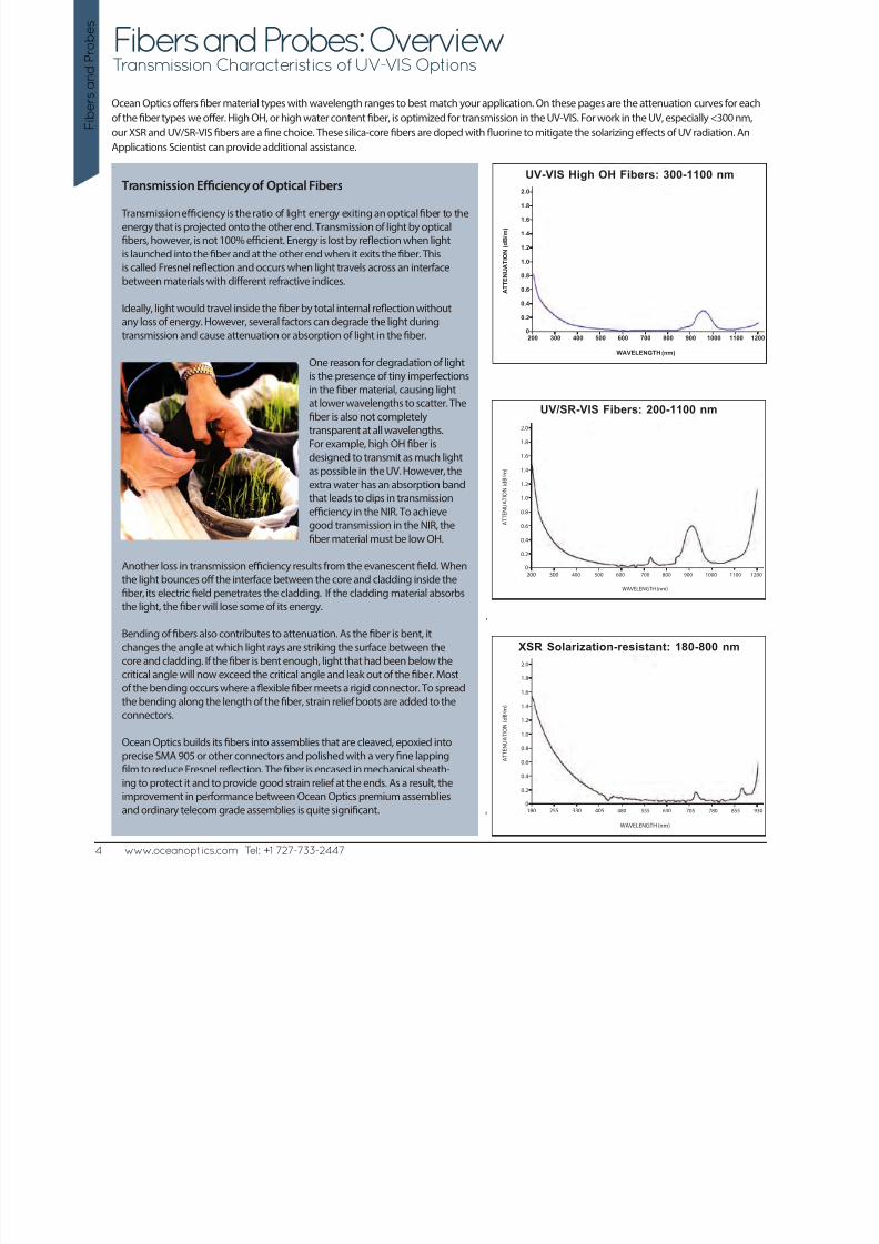
Fibers and Probes: OverviewTransmission Characteristics of UV-VIS Options
Ocean Optics offers fiber material types with wavelength ranges to best match your application. On these pages are the attenuation curves for each
of the fiber types we offer. High OH, or high water content fiber, is optimized for transmission in the UV-VIS. For work in the UV, especially <300 nm,
our XSR and UV/SR-VIS fibers are a fine choice. These silica-core fibers are doped with fluorine to mitigate the solarizing effects of UV radiation. An
Applications Scientist can provide additional assistance.
Transmission Efficiency of Optical Fibers
Transmission efficiency is the ratio of light energy exiting an optical fiber to the
energy that is projected onto the other end. Transmission of light by optical
fibers, however, is not 100% efficient. Energy is lost by reflection when light
is launched into the fiber and at the other end when it exits the fiber. Thisis called Fresnel reflection and occurs when light travels across an interface
between materials with different refractive indices.
Ideally, light would travel inside the fiber by total internal reflection without
any loss of energy. However, several factors can degrade the light during
transmission and cause attenuation or absorption of light in the fiber.
One reason for degradation of light
is the presence of tiny imperfections
in the fiber material, causing lightat lower wavelengths to scatter. The
fiber is also not completely
transparent at all wavelengths.
For example, high OH fiber is
designed to transmit as much light
as possible in the UV. However, the
extra water has an absorption band
that leads to dips in transmission
efficiency in the NIR. To achievegood transmission in the NIR, the
fiber material must be low OH.
Another loss in transmission efficiency results from the evanescent field. When
the light bounces off the interface between the core and cladding inside the
fiber, its electric field penetrates the cladding. If the cladding material absorbs
the light, the fiber will lose some of its energy.
Bending of fibers also contributes to attenuation. As the fiber is bent, it
changes the angle at which light rays are striking the surface between thecore and cladding. If the fiber is bent enough, light that had been below the
critical angle will now exceed the critical angle and leak out of the fiber. Most
of the bending occurs where a flexible fiber meets a rigid connector. To spread
the bending along the length of the fiber, strain relief boots are added to the
connectors.
Ocean Optics builds its fibers into assemblies that are cleaved, epoxied into
precise SMA 905 or other connectors and polished with a very fine lapping
film to reduce Fresnel reflection. The fiber is encased in mechanical sheath-ing to protect it and to provide good strain relief at the ends. As a result, the
improvement in performance between Ocean Optics premium assemblies
and ordinary telecom grade assemblies is quite significant.
UV-VIS High OH Fibers: 300-1100 nm
UV/SR-VIS Fibers: 200-1100 nm
XSR Solarization-resistant: 180-800 nm
8/14/2019 Ocean_Optics_Fibers_Probes.pdf
http://slidepdf.com/reader/full/oceanopticsfibersprobespdf 5/22
www.oceanoptics.com Tel: +1 727-733-2447 5
F i b er sand P r ob e
s
Fibers and Probes: Overview
0 500 1000 1500 2000 2500 3000 3500 4000 4500
A T T
E N U A T I O N ( d B / m )
WAVELENGTH (nm)
Fluoride: 300-4500 nm
3
2.5
2
1.5
1
0.5
0
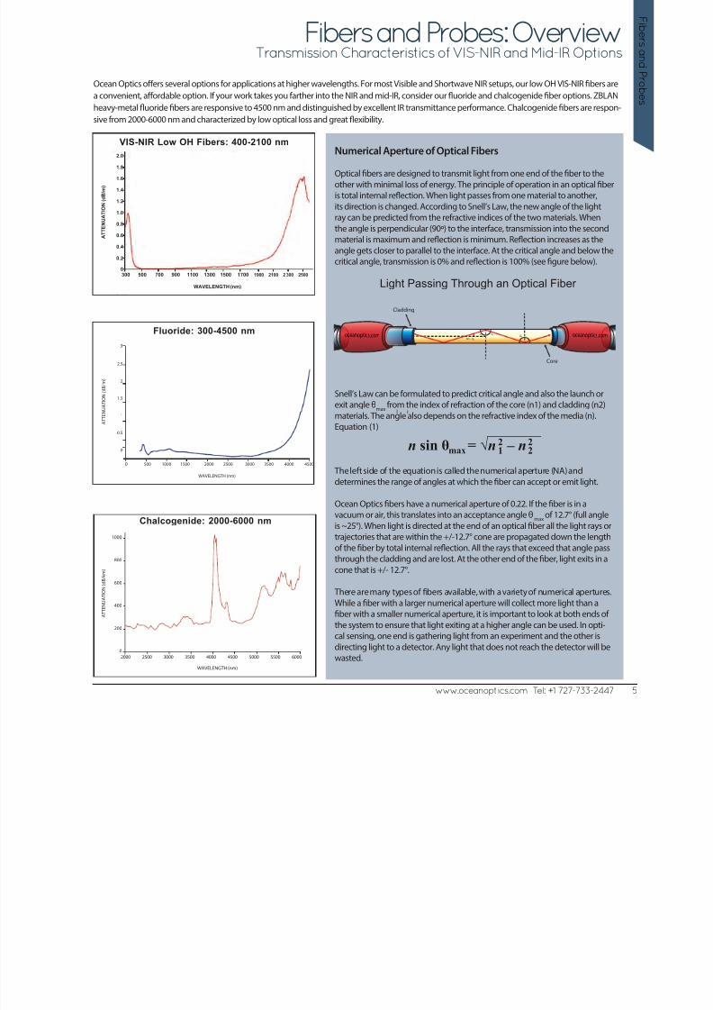
Transmission Characteristics of VIS-NIR and Mid-IR Options
Ocean Optics offers several options for applications at higher wavelengths. For most Visible and Shortwave NIR setups, our low OH VIS-NIR fibers are
a convenient, affordable option. If your work takes you farther into the NIR and mid-IR, consider our fluoride and chalcogenide fiber options. ZBLAN
heavy-metal fluoride fibers are responsive to 4500 nm and distinguished by excellent IR transmittance performance. Chalcogenide fibers are respon-
sive from 2000-6000 nm and characterized by low optical loss and great flexibility.
Numerical Aperture of Optical Fibers
Optical fibers are designed to transmit light from one end of the fiber to the
other with minimal loss of energy. The principle of operation in an optical fiber
is total internal reflection. When light passes from one material to another,
its direction is changed. According to Snell’s Law, the new angle of the lightray can be predicted from the refractive indices of the two materials. When
the angle is perpendicular (90º) to the interface, transmission into the second
material is maximum and reflection is minimum. Reflection increases as the
angle gets closer to parallel to the interface. At the critical angle and below the
critical angle, transmission is 0% and reflection is 100% (see figure below).
Snell’s Law can be formulated to predict critical angle and also the launch or
exit angle θmax
from the index of refraction of the core (n1) and cladding (n2)
materials. The angle also depends on the refractive index of the media (n).Equation (1)
The left side of the equation is called the numerical aperture (NA) and
determines the range of angles at which the fiber can accept or emit light.
Ocean Optics fibers have a numerical aperture of 0.22. If the fiber is in a
vacuum or air, this translates into an acceptance angle θmax
of 12.7° (full angle
is ~25°). When light is directed at the end of an optical fiber all the light rays or
trajectories that are within the +/-12.7° cone are propagated down the length
of the fiber by total internal reflection. All the rays that exceed that angle pass
through the cladding and are lost. At the other end of the fiber, light exits in a
cone that is +/- 12.7°.
There are many types of fibers available, with a variety of numerical apertures.
While a fiber with a larger numerical aperture will collect more light than a
fiber with a smaller numerical aperture, it is important to look at both ends of
the system to ensure that light exiting at a higher angle can be used. In opti-cal sensing, one end is gathering light from an experiment and the other is
directing light to a detector. Any light that does not reach the detector will be
wasted.2000 2500 3000 3500 4000 4500 5000 5500 6000
A T T E N U A T I O N ( d B / k m )
WAVELENGTH (nm)
Chalcogenide: 2000-6000 nm1000
800
600
400
200
0
n sin θ = √n – nmax
2
1
2
2
l i
oceanoptics.com
Core
Cladding
90 - 0c
0c 0c oceanoptics.com0c
Light Passing Through an Optical Fiber 300 500 700 900 1100 1300 1500 1700 1900 2100 2 300 2500
A T T E N U A T I O
N ( d B / m )
WAVELENGTH (nm)
2.0
1.8
1.6
1.4
1.2
1.0
0.8
0.6
0.4
0.2
0
VIS-NIR Low OH Fibers: 400-2100 nm

8/14/2019 Ocean_Optics_Fibers_Probes.pdf
http://slidepdf.com/reader/full/oceanopticsfibersprobespdf 6/226 www.oceanoptics.com Tel: +1 727-733-2447
F
i b e r s a n d P
r o b e s
Premium Grade Optical Fiber Assemblies
Keyed SMA Optical Fiber Assemblies
Our premium-grade fibers are durable, high quality fibers optimized for spectroscopy and enhanced with extra strain relief for use even in demandingenvironments. We have a full range of standard patch cords and can customize assemblies (see pages 138-139 for options). Also available are assemblies(see table at bottom) consisting of multiple fibers stacked in a linear arrangement at one end to deliver light more efficiently into the spectrometer.
Note: Fiber bend radius is expressed as Long Term (LTBR) and Short Term (STBR).
Premium-Grade Assemblies Assembly Length Jacketing Bend Radius
WavelengthRange Item Code
CoreDiameter
Buffer/Coating 0.25 m 0.5 m 1 m 1.5 m 2 m
Siliconemonocoil
Stainless-steel BX
PVDFFurcation PEEK LTBR STBR
UV-VIS HighOH Content300-1100 nm
QP50-2-UV-VISQP50-2-UV-BX
50 µm Polyimide X XX
4 cm 2 cm
QP100-2-UV-VISQP100-2-UV-BX
100 µm Polyimide X XX
4 cm 2 cm
QP200-2-UV-VISQP200-2-UV-BX
200 µm Polyimide X XX
8 cm 4 cm
QP400-1-UV-VISQP400-1-UV-BXQP400-2-UV-VISQP400-2-UV-BX
400 µm Polyimide XX
XX
X
XX
X
16 cm 8 cm
QP600-025-UV-VIS
QP600-025-UV-BXQP600-1-UV-VISQP600-1-UV-BXQP600-2-UV-VISQP600-2-UV-BX
600 µm Polyimide XX
XX
XX
X
X
X
X
X
X
24 cm 12 cm
QP1000-2-UV-VISQP1000-2-VIS-BX
1000 µm Acrylate XX
XX
40 cm 20 cm
VIS-NIR LowOH content400-2100 nm
QP8-2-VIS-NIR 8 µm Acrylate X X 4 cm 2 cm
QP50-2-VIS-NIRQP50-2-VIS-BX
50 µm Polyimide XX
XX
4 cm 2 cm
QP100-2-VIS-NIRQP100-2-VIS-BX
100 µm Polyimide XX
XX
4 cm 2 cm
QP200-2-VIS-NIRQP200-2-VIS-BX
200 µm Polyimide XX
XX
8 cm 4 cm
QP400-1-VIS-NIRQP400-1-VIS-BXQP400-2-VIS-NIRQP400-2-VIS-BX
400 µm Polyimide XX
XX
X
XX
X
16 cm 8 cm
QP600-025-VIS-NIR
QP600-025-VIS-BXQP600-1-VIS-NIR
QP600-1-VIS-BXQP600-2-VIS-NIRQP600-2-VIS-BX
600 µm Polyimide XX
X
X XX
X
X
X
X
XX
24 cm 12 cm
QP1000-2-VIS-NIRQP1000-2-VIS-BX
1000 µm Acrylate XX
XX
40 cm 20 cm
Fluoride300-4500 nm
P450-0.5-FLUORIDE
P450-1.5-FLUORIDE
P450-1-FLUORIDE
450 µm Acrylate XX
X
XXX
15 cm 8 cm
Chalcogenide2000-6000 nm
P500-0.5-CHALP500-1-CHAL
500 µm Fluoropoly-mer andPVC
XX
XX
7.5cm
7.5cm
Keyed SMA Optical Fiber Assemblies,
Round to Keyed Linear Assembly Length Jacketing
Wavelength
Range Item Code
Core
Diameter
Buffer/
Coating 0.25 m 0.5 m 1 m 1.5 m 2 m
Silicone
monocoil
Stainless-
steel BX
PVDF
Furcation PEEK LTBR STBR
300-1100 nm PL100-2-UV-VIS 100 µm ± 3 µm Polyimide x x 4 cm 2 cm
400-2100 nm PL100-2-VIS-NIR 100 µm ± 3 µm Polyimide x x 4 cm 2 cm
300-1100 nm and
400-2100 nm
PL100-2-MIXED 100 µm ± 3 µm Polyimide x
x
x
x
4 cm 2 cm
300-1100nm and
400-2100 nm
PL200-2-MIXED 200 µm ± 4 µm Polyimide x x 8 cm 4 cm

8/14/2019 Ocean_Optics_Fibers_Probes.pdf
http://slidepdf.com/reader/full/oceanopticsfibersprobespdf 7/22
Bifurcated Optical Fiber Assemblies
www.oceanoptics.com Tel: +1 727-733-2447 7
F i b er sand P r ob e
s
Premium-grade bifurcated assemblies have two fibers in the common end of the assembly that break out into separate legs. Splitters comprise three
fibers epoxied at the nexus of a Y-shaped assembly and have lower transmission efficiency than bifurcated fibers.
We offer two types of solarization-resistant fiber assemblies, which prevent transmission degradation in the UV: polyimide-buffer fibers for applica-
tions <300 nm and aluminum-buffer fibers that offer enhanced UV transmission (signal will transmit to 180 nm) and resistance to UV degradation.
Premium-grade Bifurcated Optical Fiber AssembliesAssembly
Length JacketingBend
Radius
Wavelength Range Item Code Core Diameter Buffer/Coating 2 m Siliconemonocoil Stainless-steel BX LTBR STBR
VIS-NIR Low OHcontent 400-2100 nm
QBIF50-VIS-NIR 50 µm Polyimide X X
QBIF200-VIS-NIRQBIF200-NIR-BX
200 µm Polyimide XX
XX
8 cm 4 cm
QBIF400-VIS-NIRQBIF400-NIR-BX
400 µm Polyimide XX
XX
16 cm 8 cm
QBIF600-VIS-NIRQBIF600-NIR-BX
600 µm Polyimide XX
XX
24 cm 12 cm
UV-VIS High OHContent 300-1100 nm
QBIF50-UV-VIS 50 µm Polyimide X X 4 cm 2 cm
QBIF200-UV-VIS 200 µm Polyimide X X 8 cm 4 cm
QBIF400-UV-VIS 400 µm Polyimide X X 16 cm 8 cm
QBIF600-UV-VIS 600 µm Polyimide X X 24 cm 12 cm
300-1100 nm and400-2100 nm (Mixed)
QBIF200-MIXED 200 µm Polyimide X X 8 cm 4 cm
QBIF400-MIXED 400 µm Polyimide X X 16 cm 8 cm
Splitter Optical Fiber Assemblies
VIS-NIR Low OH con-tent 400-2100 nm
SPLIT200-VIS-NIR 200 µm Polyimide X X 8 cm 4 cm
SPLIT400-VIS-NIR 400 µm Polyimide X X 16 cm 8 cm
UV-VIS High OHContent 300-1100 nm SPLIT200-UV-VIS 200 µm Polyimide X X 8 cm 4 cmSPLIT400-UV-VIS 400 µm Polyimide X X 16 cm 8 cm
Solarization Resistant Optical Fiber Assemblies
Extreme Solarization-Resistant Assembly Length Jacketing Bend Radius
Wavelength Range Item CodeCoreDiameter
Buffer/Coating 0.25 m 0.5 m 1 m 1.5 m 2 m
Siliconemonocoil
Stainless-steel BX LTBR STBR
UV/SR-VIS High OHcontent 200-1100 nm
QP200-2-SR-BX 200 µm Polyimide X X 8 cm 2 cm
QP300-1-SRQP300-1-SR-BX
300 µm Polyimide XX
XX
12 cm 6 cm
QP400-025-SRQP400-025-SR-BXQP400-2-SRQP400-2-SR-BX
400 µm Polyimide XX
XX
X
XX
X
16 cm 8 cm
QP600-025-SR
QP600-025-SR-BXQP600-1-SRQP600-1-SR-BXQP600-2-SRQP600-2-SR-BX
600 µm Polyimide X
X XX
XX
X
X
X
X
X
X
24 cm 12 cm
UV-VIS XSRSolarization-resistant180-900 nm
QP115-025-XSR-BXQP115-1-XSR-BXQP115-2-XSR-BX
115 µm Aluminum(Primary)
XX
X
XXX
4 cm 2 cm
QP230-025-XSR-BXQP230-1-XSR-BXQP230-2-XSR-BX
230 µm Aluminum(Primary)
XX
X
XXX
4 cm 2 cm
QP455-025-XSR-BX
QP455-1-XSR-BXQP455-2-XSR-BX
455 µm Aluminum
(Primary)
X
XX
X
XX
8 cm 4 cm
QP600-025-XSR-BXQP600-1-XSR-BXQP600-2-XSR-BX
600 µm Aluminum(Primary)
XX
X
XXX
24 cm 12 cm
Note: Fiber bend radius is expressed as Long Term (LTBR) and Short Term (STBR).

8/14/2019 Ocean_Optics_Fibers_Probes.pdf
http://slidepdf.com/reader/full/oceanopticsfibersprobespdf 8/22
8/14/2019 Ocean_Optics_Fibers_Probes.pdf
http://slidepdf.com/reader/full/oceanopticsfibersprobespdf 9/22
8/14/2019 Ocean_Optics_Fibers_Probes.pdf
http://slidepdf.com/reader/full/oceanopticsfibersprobespdf 10/22
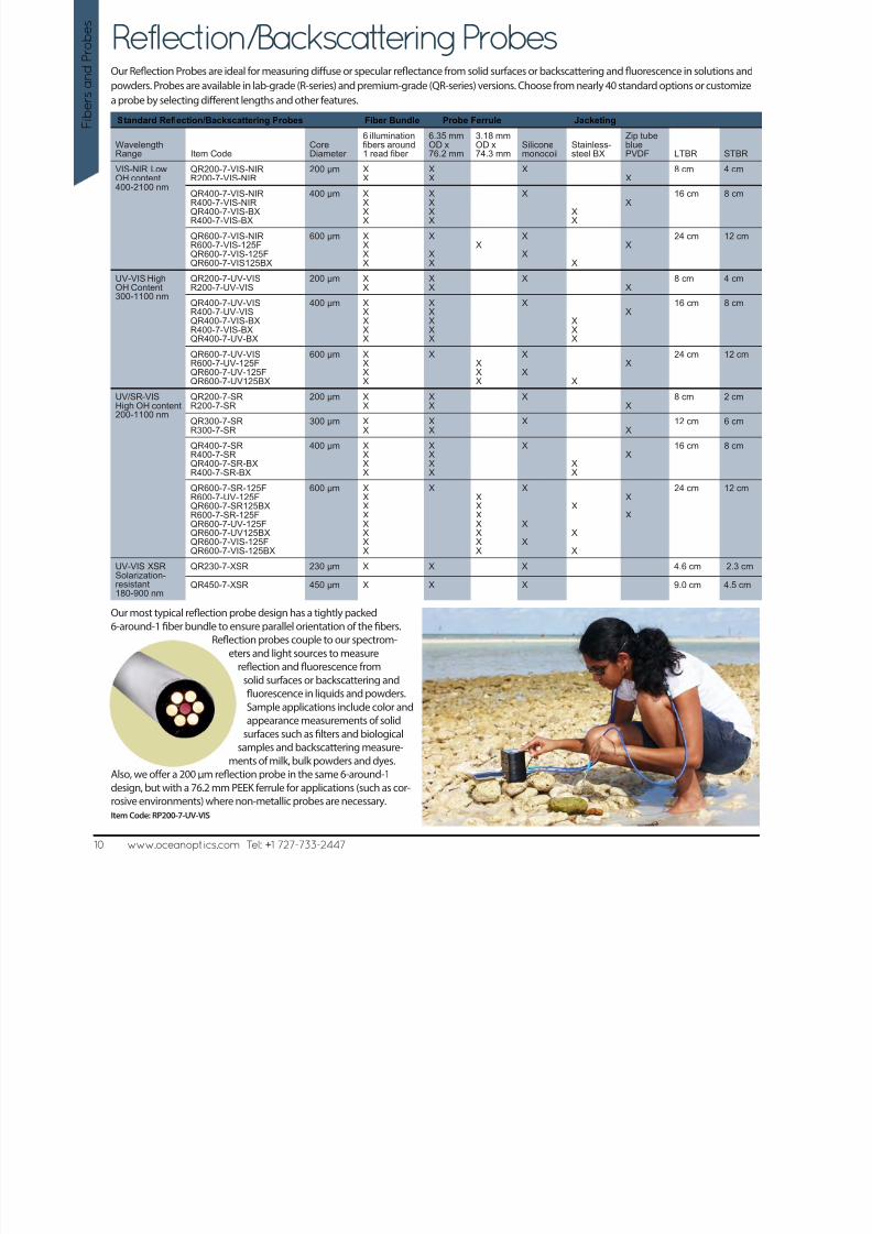
Reflection/Backscattering ProbesOur Reflection Probes are ideal for measuring diffuse or specular reflectance from solid surfaces or backscattering and fluorescence in solutions and
powders. Probes are available in lab-grade (R-series) and premium-grade (QR-series) versions. Choose from nearly 40 standard options or customize
a probe by selecting different lengths and other features.
Our most typical reflection probe design has a tightly packed
6-around-1 fiber bundle to ensure parallel orientation of the fibers.
Reflection probes couple to our spectrom-eters and light sources to measure
reflection and fluorescence from
solid surfaces or backscattering and
fluorescence in liquids and powders.
Sample applications include color and
appearance measurements of solid
surfaces such as filters and biological
samples and backscattering measure-
ments of milk, bulk powders and dyes.Also, we offer a 200 µm reflection probe in the same 6-around-1
design, but with a 76.2 mm PEEK ferrule for applications (such as cor-
rosive environments) where non-metallic probes are necessary.
Item Code: RP200-7-UV-VIS
Standard Reflection/Backscattering Probes Fiber Bundle Probe Ferrule Jacketing
WavelengthRange Item Code
CoreDiameter
6 illuminationfibers around1 read fiber
6.35 mmOD x76.2 mm
3.18 mmOD x74.3 mm
Siliconemonocoil
Stainless-steel BX
Zip tubebluePVDF LTBR STBR
VIS-NIR LowOH content400-2100 nm
QR200-7-VIS-NIRR200-7-VIS-NIR
200 µm XX
XX
XX
8 cm 4 cm
QR400-7-VIS-NIRR400-7-VIS-NIRQR400-7-VIS-BXR400-7-VIS-BX
400 µm XXXX
XXXX
X
XX
X
16 cm 8 cm
QR600-7-VIS-NIRR600-7-VIS-125F
QR600-7-VIS-125FQR600-7-VIS125BX
600 µm XX
XX
X
XX
XX
X X
X
24 cm 12 cm
UV-VIS HighOH Content300-1100 nm
QR200-7-UV-VISR200-7-UV-VIS
200 µm XX
XX
XX
8 cm 4 cm
QR400-7-UV-VISR400-7-UV-VISQR400-7-VIS-BXR400-7-VIS-BXQR400-7-UV-BX
400 µm XXXXX
XXXXX
X
XXX
X16 cm 8 cm
QR600-7-UV-VISR600-7-UV-125FQR600-7-UV-125F
QR600-7-UV125BX
600 µm XXX
X
XXX
X
X
X
X
X
24 cm 12 cm
UV/SR-VISHigh OH content200-1100 nm
QR200-7-SRR200-7-SR
200 µm XX
XX
XX
8 cm 2 cm
QR300-7-SRR300-7-SR
300 µm XX
XX
XX
12 cm 6 cm
QR400-7-SRR400-7-SRQR400-7-SR-BXR400-7-SR-BX
400 µm XXXX
XXXX
X
XX
X
16 cm 8 cm
QR600-7-SR-125FR600-7-UV-125FQR600-7-SR125BXR600-7-SR-125FQR600-7-UV-125FQR600-7-UV125BXQR600-7-VIS-125FQR600-7-VIS-125BX
600 µm XXXXXXXX
XXXXXXXX
X
X
X
X
X
X
X
X
24 cm 12 cm
UV-VIS XSRSolarization-resistant180-900 nm
QR230-7-XSR 230 µm X X X 4.6 cm 2.3 cm
QR450-7-XSR 450 µm X X X 9.0 cm 4.5 cm
10 www.oceanoptics.com Tel: +1 727-733-2447
F
i b e r s a n d P
r o b e s

8/14/2019 Ocean_Optics_Fibers_Probes.pdf
http://slidepdf.com/reader/full/oceanopticsfibersprobespdf 11/22 www.oceanoptics.com Tel: +1 727-733-2447 11
F i b er sand P r ob e
s
Reflection/Backscattering ProbesReflection Probes with Reference Leg Fiber Bundle Probe Ferrule Jacketing
Wavelength
Range Item Code
Core
Diameter
6 illumination fibers
around 1 read
6.35 mm
OD
3.18 mm
OD
Silicone
monocoil
Zip tube blue
PVDF LTBR STBR
VIS-NIR Low
OH content400-2100 nm
QR200-7-REF-VIS-NIR
R200-7-REF-VIS-NIR
200 µm X
X
X
X
X
X
8 cm 4 cm
UV-VIS High
OH Content
300-1100 nm
QR200-7-REF-UV-VIS
R200-7-REF-UV-VIS
200 µm X
X
X
X
X
X
8 cm 4 cm
Reflection/Backscattering Probes for Expanded Wavelength Coverage
UV-VIS and
VIS-NIR
300-1100 nm
and
400-2100 nm
QR200-12-MIXED
R200-12-MIXED
200 µm 6 UV-VIS and 6
VIS-NIR illumina-
tion fibers around
1 UV-VIS and
1 VIS-NIR fibers
X
X
X
X
8 cm 4 cm
Angled Probes for Solutions and Powders
VIS-NIR Low
OH content
400-2100 nm
QR200-7-ANGLE-VIS
R200-7-ANGLE-VIS
200 µm X
X
X
X
X
X
8 cm 4 cm
QR400-7-ANGLE-VIS
R400-7-ANGLE-VIS
QR400-ANGLE-VIS
400 µm X
X
X
X
X
X
X
X
X
16 cm 8 cm
UV-VIS HighOH Content
300-1100 nm
QR200-7-ANGLE-UVR200-7-ANGLE-UV
200 µm XX
XX
XX
8 cm 4 cm
QR400-7-ANGLE-UV
R400-7-ANGLE-UV
QR400-ANGLE-UV
400 µm X
X
X
X
X
X
X
X
X
16 cm 8 cm
o c eano p t i c s.c o m
ocea no p t ics.co
m
oceanoptics.comA
A
B
A = Read Fiber
B = Dummy Fiber
Angled Reflection Probe
Our Angled Reflection Probes have a 6-around-1 fiber design with a 30º window
to remove specular effects when the probe is immersed in liquids or powders.
o c e a n o p t
i c s. c o m
ocea no p t ics.co m
oceanoptics.comA
A
A = Read Fiber
B = ReferenceFiber
B
B
Reflection Probe With Reference Leg
In this design, an additional fiber leg is added to the probe to monitor an
illumination or reference source. This is useful where the changing output of the
source needs continuous monitoring.
The QR200-12-MIXED has 14 fibers -- six UV-VIS and six VIS-NIR illumination fibers, plus one UV-VIS and one VIS-NIR readfiber (see bundle photo at left). It couples easily to a dual-channel spectrometer in which each channel is set for a different
wavelength range.Item Code: QR200-12-MIXED
Reflection/Backscattering Probes for Expanded Wavelength Coverage

8/14/2019 Ocean_Optics_Fibers_Probes.pdf
http://slidepdf.com/reader/full/oceanopticsfibersprobespdf 12/2212 www.oceanoptics.com Tel: +1 727-733-2447
F i b e r s a n d P
r o b e s
FL-400Flame-resistant Fiber Probe
The FL-400 is a heat-resistant fiber optic probe that couples to Ocean Optics
miniature fiber optic spectrometers to measure in situ emission spectra of
samples such as dissolved metals and high-temperature plasmas.
High-temperature Fiber The FL-400 Flame-resistant Fiber Probe consists of a high-temperature
400 µm gold-jacketed UV-VIS optical fiber in an 8-inch-long stainless steel
sleeve. The probe is connected with a splice bushing to a standard SMA-
terminated patch cord, which couples to the spectrometer to measure
emission spectra.
Spectroscopy Teaching Tool The FL-400 Flame-resistant Fiber Probe is especially beneficial as an emis-
sion spectroscopy teaching tool for use with Ocean Optics’ CHEM4-series
of low-cost, UV-VIS teaching-lab spectrophotometers. Use the probe in two
ways:
- By introducing it into emission sample environments up to 750 °C
- By attaching the nickel wire loop at the probe tip so that users can
observe flame emission spectra of samples such as sodium, potassium,calcium and copper
Item Code: FL-400
Fiber core diameter: 400 µm
Assembly length: 20 cm (8”)
Fiber core/cladding: Silica
Fiber core/cladding
diameter:
400 µm/440 µm
Fiber jacketing: Gold
Fiber buffer/tube diameter:
510 µm/0.9 µm
Fiber bundle: 1 single-strand, multi-mode read fiber
Wavelengths covered: 300-1100 nm
Probe sleeve (ferrule): Stainless steel
Flame loop: Nickel chromium 24 AWG
Temperature range: -269º C to 750º C
Numerical aperture: 0.22
Fiber termination: SMA 905
THAT’S HOT!
Handheld, modular spectrometers for irradiance measurements of solar cels and solar simulators.
• Modular, miniature spectrometers that are ideal for use withsolar simulators
• Characterization of dye-sensitive and organic cells
• Quality control of photovoltaic panels
• OEM sensing systems for a variety of solar production needs
Find out how Ocean Optics can help you improve quality, increase efficiency and boost profit.
www.oceanoptics.com/solar.asp
8/14/2019 Ocean_Optics_Fibers_Probes.pdf
http://slidepdf.com/reader/full/oceanopticsfibersprobespdf 13/22
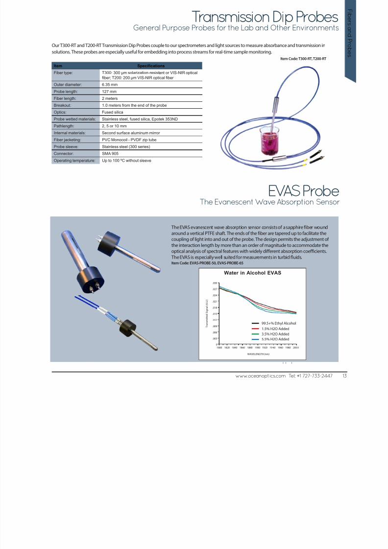
Transmission Dip ProbesGeneral Purpose Probes for the Lab and Other Environments
www.oceanoptics.com Tel: +1 727-733-2447 13
F i b er sand P r ob e
s
Our T300-RT and T200-RT Transmission Dip Probes couple to our spectrometers and light sources to measure absorbance and transmission in
solutions. These probes are especially useful for embedding into process streams for real-time sample monitoring.
Item Code: T300-RT, T200-RT
Item Specifications
Fiber type: T300: 300 µm solarization-resistant or VIS-NIR optical
fiber; T200: 200 µm VIS-NIR optical fiber
Outer diameter: 6.35 mm
Probe length: 127 mm
Fiber length: 2 meters
Breakout: 1.0 meters from the end of the probe
Optics: Fused silicaProbe wetted materials: Stainless steel, fused silica, Epotek 353ND
Pathlength: 2, 5 or 10 mm
Internal materials: Second surface aluminum mirror
Fiber jacketing: PVC Monocoil - PVDF zip tube
Probe sleeve: Stainless steel (300 series)
Connector: SMA 905
Operating temperature: Up to 100 ºC without sleeve
EVAS ProbeThe Evanescent Wave Absorption Sensor
The EVAS evanescent wave absorption sensor consists of a sapphire fiber woundaround a vertical PTFE shaft. The ends of the fiber are tapered up to facilitate the
coupling of light into and out of the probe. The design permits the adjustment of
the interaction length by more than an order of magnitude to accommodate the
optical analysis of spectral features with widely different absorption coefficients.
The EVAS is especially well suited for measurements in turbid fluids.Item Code: EVAS-PROBE-50, EVAS-PROBE-65
l l l
99.5+% Ethyl Alcohol
1.5% H2O Added
3.5% H2O Added
5.5% H2O Added1800 1820 1840 1860 1880 1900 1920 19 40 1960 1980 200 0
T r a n s m i t t e d S i g n a l ( A . U . )
WAVELENGTH (nm)
Water in Alcohol EVAS
.030
.027
.024
.021
.018
.015
.012
.009
.006
.003
0
8/14/2019 Ocean_Optics_Fibers_Probes.pdf
http://slidepdf.com/reader/full/oceanopticsfibersprobespdf 14/22
Transmission ProbesTransmission Dip Probes for Hostile Environments
The TP300-UV-VIS Transmission Dip Probe couples to our
spectrometers and light sources to measure the absorbance and
transmission of solutions in harsh environments.
Also, the TP300-UV-VIS Probe is a chemically inert PEEK
transmission probe that can be equipped with a tip (RT-PH) for
mounting transmissive pH films in the optical path. Light is directed
via one fiber through the mounted
film to a mirror. Then light is redi-
rected back through the film to
a receive fiber that returns the
light to the spectrometer.
The sample is free to flow
over the sides of the
film.
By using an
RTP-2-10 (adjustable 2-10 mm)
Transmission Tip, the TP300-UV-VIS can be used
for routine transmission measurements.
Item Code: TP300-UV-VIS
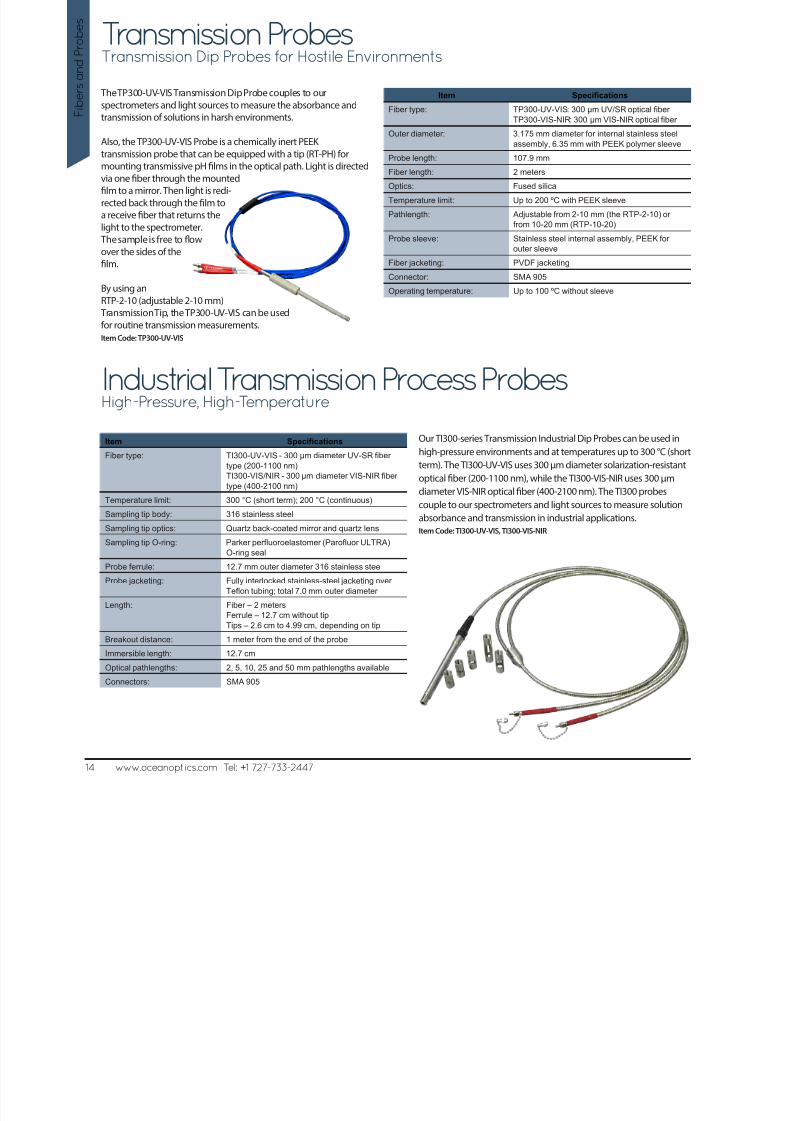
Our TI300-series Transmission Industrial Dip Probes can be used in
high-pressure environments and at temperatures up to 300 °C (short
term). The TI300-UV-VIS uses 300 µm diameter solarization-resistantoptical fiber (200-1100 nm), while the TI300-VIS-NIR uses 300 µm
diameter VIS-NIR optical fiber (400-2100 nm). The TI300 probes
couple to our spectrometers and light sources to measure solution
absorbance and transmission in industrial applications.
Item Code: TI300-UV-VIS, TI300-VIS-NIR
Item Specifications
Fiber type: TP300-UV-VIS: 300 µm UV/SR optical fiber
TP300-VIS-NIR: 300 µm VIS-NIR optical fiber
Outer diameter: 3.175 mm diameter for internal stainless steel
assembly, 6.35 mm with PEEK polymer sleeve
Probe length: 107.9 mm
Fiber length: 2 meters
Optics: Fused silica
Temperature limit: Up to 200 ºC with PEEK sleeve
Pathlength: Adjustable from 2-10 mm (the RTP-2-10) or
from 10-20 mm (RTP-10-20)
Probe sleeve: Stainless steel internal assembly, PEEK for
outer sleeve
Fiber jacketing: PVDF jacketing
Connector: SMA 905
Operating temperature: Up to 100 ºC without sleeve
Item Specifications
Fiber type: TI300-UV-VIS - 300 µm diameter UV-SR fiber
type (200-1100 nm)TI300-VIS/NIR - 300 µm diameter VIS-NIR fiber
type (400-2100 nm)
Temperature limit: 300 °C (short term); 200 °C (continuous)
Sampling tip body: 316 stainless steel
Sampling tip optics: Quartz back-coated mirror and quartz lens
Sampling tip O-ring: Parker perfluoroelastomer (Parofluor ULTRA)
O-ring seal
Probe ferrule: 12.7 mm outer diameter 316 stainless steel
Probe jacketing: Fully interlocked stainless-steel jacketing overTeflon tubing; total 7.0 mm outer diameter
Length: Fiber – 2 meters
Ferrule – 12.7 cm without tip
Tips – 2.6 cm to 4.99 cm, depending on tip
Breakout distance: 1 meter from the end of the probe
Immersible length: 12.7 cm
Optical pathlengths: 2, 5, 10, 25 and 50 mm pathlengths available
Connectors: SMA 905
14 www.oceanoptics.com Tel: +1 727-733-2447
F i b e r s a n d P
r o b e s
Industrial Transmission Process ProbesHigh-Pressure, High-Temperature

8/14/2019 Ocean_Optics_Fibers_Probes.pdf
http://slidepdf.com/reader/full/oceanopticsfibersprobespdf 15/22
Single and Double Pass Transmission ProbesRobust Transmission Probes for Process Applications
The PRO-PROBE-ATR Probe is an Attenuated Total Reflection Probe designed for measuring highly absorbent samples. The ATR Probe is ideal
for applications where the absorbance of samples is in the 4000-5000 AU/cm range. The ATR Probe can be inserted directly into the sample andspectra can be taken without sample dilution. Typical applications involve measurement of pure inks, dyes and crude oil samples. What’s more,
the ATR Probe can be used as a general deposition probe if the refractive index (RI) of the material that is depositing on the probe tip is greater
than the RI of the ATR’s sapphire crystal or is greater than 1.7.Item Code: PRO-PROBE-ATR
Single Pass Double Pass
Recommended fiber diameter: 600 µm 600 µm
Outer diameter: 25.4 mm (1.0") 19.1 mm (0.75")
Probe length: ~305 mm ~305 mm
Pathlength: 1 mm-10 mm; please specify 2 mm-20 mm; please specifyBody materials: 316 stainless steel (standard); Hastelloy C, Titanium and
Monel also available
316 stainless steel (standard); Hastelloy C, Titanium and
Monel also available
Window materials: Quartz (standard); sapphire also avai lable Quartz (standard); sapphire also available
Seals: Viton (standard); Chemraz, Kalrez also available Viton (standard); Chemraz, Kalrez also available
Pressure limit: 7,000 psig 7,000 psig
Fiber connections: SMA 905 SMA 905
Temperature limit: 300 ºC for probe body 300 ºC for probe body
Wavelength range: UV-NIR UV-NIR
Fiber jacketing: PVDF jacketing PVDF jacketing
Connector: SMA 905 SMA 905
Operating temperature: Up to 100 ºC without sleeve Up to 100 ºC without sleeve
Single- and Double-Pass Transmission Probes are process-ready probes useful for online measurements (200-2400 nm) of sample streams. The
probes send light energy from a source through the sample by offset-folding the beam 180º and back via a protected reflector. The transmitted/
absorbed light is carried back to a spectrophotometer where the intensity of the returning optical energy can be converted to concentration units.
Specify Single-pass Probes for pathlengths from 1-6 mm and Double-pass Probes for pathlengths from 5-20 mm.Item Code: PRO-PROBE-SPP, PRO-PROBE-TR
www.oceanoptics.com Tel: +1 727-733-2447 15
F i b er sand P r ob e
s
Attenuated Total Reflection ProbeIdeal for Samples with High Optical Density
Item Specications
Recommended fiber diameter: 600 µm
Outer diameter: 19 mm (0.75")
Probe length: ~305 mm
Body materials: 316 stainless steel (standard); Hastelloy C,Titanium and Monel also available
Crystal material: Sapphire
Seals: Viton (standard); Chemraz, Kalrez also available
Pressure limit: 10,000 psig
Fiber connections: SMA 905
Temperature limit: 300 ºC
Wavelength range: UV-NIR
8/14/2019 Ocean_Optics_Fibers_Probes.pdf
http://slidepdf.com/reader/full/oceanopticsfibersprobespdf 16/22
F I b e r s a n d P
r o b e s
16 www.oceanoptics.com Tel: +1 727-733-2447
OptoTemp Probes
Front-Surface Fluorescence Probe
Fiber Optic Thermometer - Contact up to 950 °C
Real-Time Fluorescence Monitoring
Designed for reliable operation in harsh chemical and electrical environments, the OptoTemp 2000 is unaffected by microwave radiation and plasma.
It measures temperature using fluorescent decay, a field-proven technique in hundreds of industrial installations for 25 years.
Item Code: OPTOTEMP-FLEX, OPTOTEMP-SUPER, OPTOTEMP-ULTRA
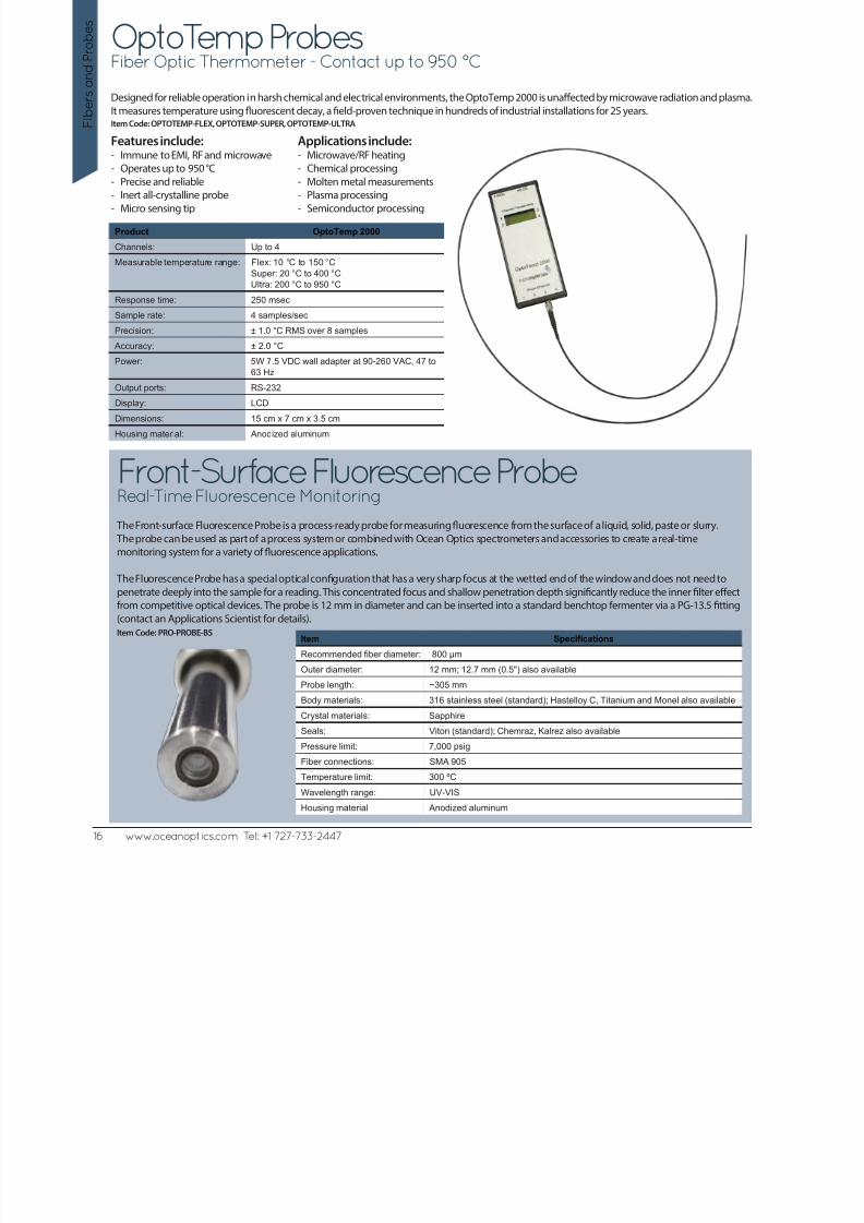
The Front-surface Fluorescence Probe is a process-ready probe for measuring fluorescence from the surface of a liquid, solid, paste or slurry.
The probe can be used as part of a process system or combined with Ocean Optics spectrometers and accessories to create a real-time
monitoring system for a variety of fluorescence applications.
The Fluorescence Probe has a special optical configuration that has a very sharp focus at the wetted end of the window and does not need to
penetrate deeply into the sample for a reading. This concentrated focus and shallow penetration depth significantly reduce the inner filter effect
from competitive optical devices. The probe is 12 mm in diameter and can be inserted into a standard benchtop fermenter via a PG-13.5 fitting
(contact an Applications Scientist for details).
Item Code: PRO-PROBE-BS
Product OptoTemp 2000
Channels: Up to 4
Measurable temperature range: Flex: 10 °C to 150 °C
Super: 20 °C to 400 °C
Ultra: 200 °C to 950 °C
Response time: 250 msec
Sample rate: 4 samples/sec
Precision: ± 1.0 °C RMS over 8 samples
Accuracy: ± 2.0 °C
Power: 5W 7.5 VDC wall adapter at 90-260 VAC, 47 to
63 Hz
Output ports: RS-232
Display: LCD
Dimensions: 15 cm x 7 cm x 3.5 cm
Housing material: Anodized aluminum
Item Specifications
Recommended fiber diameter: 800 µm
Outer diameter: 12 mm; 12.7 mm (0.5") also available
Probe length: ~305 mm
Body materials: 316 stainless steel (standard); Hastelloy C, Titanium and Monel also available
Crystal materials: Sapphire
Seals: Viton (standard); Chemraz, Kalrez also available
Pressure limit: 7,000 psig
Fiber connections: SMA 905
Temperature limit: 300 ºC
Wavelength range: UV-VIS
Housing material Anodized aluminum
Features include:- Immune to EMI, RF and microwave
- Operates up to 950 °C
- Precise and reliable
- Inert all-crystalline probe
- Micro sensing tip
Applications include:- Microwave/RF heating
- Chemical processing
- Molten metal measurements
- Plasma processing
- Semiconductor processing
8/14/2019 Ocean_Optics_Fibers_Probes.pdf
http://slidepdf.com/reader/full/oceanopticsfibersprobespdf 17/22
www.oceanoptics.com Tel: +1 727-733-2447 17
F i b er sand P r ob e
s
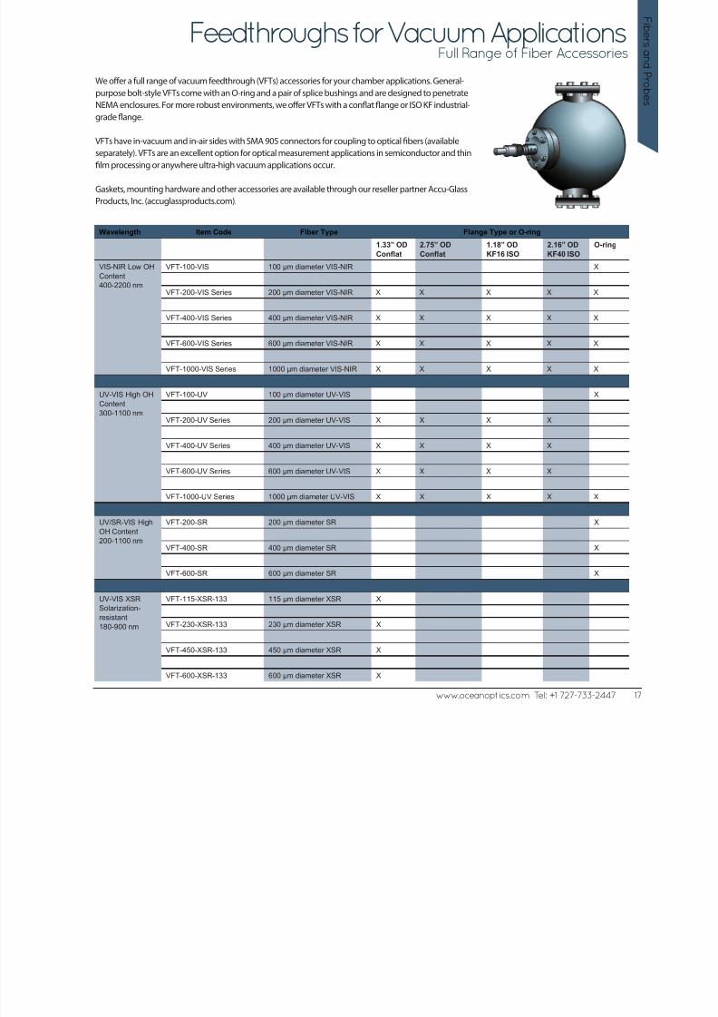
Feedthroughs for Vacuum ApplicationsFull Range of Fiber Accessories
We offer a full range of vacuum feedthrough (VFTs) accessories for your chamber applications. General-
purpose bolt-style VFTs come with an O-ring and a pair of splice bushings and are designed to penetrate
NEMA enclosures. For more robust environments, we offer VFTs with a conflat flange or ISO KF industrial-grade flange.
VFTs have in-vacuum and in-air sides with SMA 905 connectors for coupling to optical fibers (available
separately). VFTs are an excellent option for optical measurement applications in semiconductor and thin
film processing or anywhere ultra-high vacuum applications occur.
Gaskets, mounting hardware and other accessories are available through our reseller partner Accu-Glass
Products, Inc. (accuglassproducts.com).
Wavelength Item Code Fiber Type Flange Type or O-ring
1.33” OD
Conflat
2.75” OD
Conflat
1.18” OD
KF16 ISO
2.16” OD
KF40 ISO
O-ring
VIS-NIR Low OH
Content
400-2200 nm
VFT-100-VIS 100 µm diameter VIS-NIR X
VFT-200-VIS Series 200 µm diameter VIS-NIR X X X X X
VFT-400-VIS Series 400 µm diameter VIS-NIR X X X X X
VFT-600-VIS Series 600 µm diameter VIS-NIR X X X X X
VFT-1000-VIS Series 1000 µm diameter VIS-NIR X X X X X
UV-VIS High OH
Content
300-1100 nm
VFT-100-UV 100 µm diameter UV-VIS X
VFT-200-UV Series 200 µm diameter UV-VIS X X X X
VFT-400-UV Series 400 µm diameter UV-VIS X X X X
VFT-600-UV Series 600 µm diameter UV-VIS X X X X
VFT-1000-UV Series 1000 µm diameter UV-VIS X X X X X
UV/SR-VIS High
OH Content
200-1100 nm
VFT-200-SR 200 µm diameter SR X
VFT-400-SR 400 µm diameter SR X
VFT-600-SR 600 µm diameter SR X
UV-VIS XSR
Solarization-
resistant
180-900 nm
VFT-115-XSR-133 115 µm diameter XSR X
VFT-230-XSR-133 230 µm diameter XSR X
VFT-450-XSR-133 450 µm diameter XSR X
VFT-600-XSR-133 600 µm diameter XSR X
8/14/2019 Ocean_Optics_Fibers_Probes.pdf
http://slidepdf.com/reader/full/oceanopticsfibersprobespdf 18/22
F i b e r s a n d P
r o b e s
18 www.oceanoptics.com Tel: +1 727-733-2447
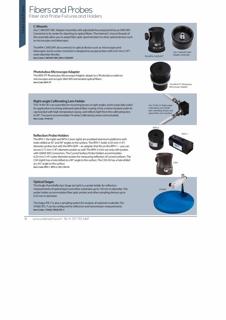
Fibers and ProbesFiber and Probe Fixtures and Holders
The C-MOUNT-MIC
Adapter Assembly
RPH-1
CSH
STAGE
The MFA-C-MOUNT
The 74-90-UV Right-angle
Collimating Lens Holder
with collimating lenses and
optical fiber (not included)
The MFA-PT Phototubus
Microscope Adapter
RPH-2
C-MountsOur C-MOUNT-MIC Adapter Assembly with adjustable focusing barrel has an SMA 905
Connector in its center for attaching to optical fibers. The internal C-mount threads ofthis assembly allow you to adapt fiber optic spectrometers to other optical devices such
as microscopes and telescopes.
The MFA-C-MOUNT also connects to optical devices such as microscopes and
telescopes, but its center connector is designed to accept probes with 6.35-mm (1/4”)
outer diameter ferrules.Item Code: C-MOUNT-MIC, MFA-C-MOUNT
Phototubus Microscope Adapter The MFA-PT Phototubus Microscope Adapter adapts to a Phototubus outlet on
microscopes and accepts SMA 905-terminated optical fibers.Item Code: MFA-PT
Right-angle Collimating Lens Holder The 74-90-UV is an assembly for mounting lenses at right angles, and is especially useful
for applications involving awkward optical fiber routing. It has a mirror located under its
cap bonded with high-temperature epoxy, and reflects light from the collimating lens
to 90°. Two ports accommodate 74-series Collimating Lenses (not included).Item Code: 74-90-UV
Reflection Probe Holders The RPH-1 (far right) and RPH-2 (near right) are anodized aluminum platforms with
holes drilled at 45° and 90° angles to the surface. The RPH-1 holds 6.35-mm (1/4”)
diameter probes but with the RPH-ADP -- an adapter that fits on the RPH-1 -- you can
secure 3.17 mm (1/8”) diameter probes as well. The RPH-2 is for use only with probes
with QSMA 905 Connectors. The Curved Surface Probe Holders accommodate
6.35-mm (1/4”) outer diameter probes for measuring reflection of curved surfaces. The
CSH (right) has a hole drilled at a 90° angle to the surface. The CSH-45 has a hole drilled
at a 45° angle to the surface.Item Code: RPH-1, RPH-2, CSH, CSH-45
Optical Stages The Single-Point Reflection Stage (at right) is a probe holder for reflection
measurements of optical layers and other substrates up to 150 mm in diameter. The
probe holder accommodates fiber optic probes and other sampling devices up to
6.35 mm in diameter.
The Stage-RTL-T is also a sampling system for analysis of substrate materials. The
STAGE-RTL-T can be configured for reflection and transmission measurements.Item Codes: STAGE, STAGE-RTL-T

8/14/2019 Ocean_Optics_Fibers_Probes.pdf
http://slidepdf.com/reader/full/oceanopticsfibersprobespdf 19/22
www.oceanoptics.com Tel: +1 727-733-2447 19
F i b er sand P r ob e
s
Fibers and ProbesFiber and Probe Accessories
Bulkhead Bushing
The 21-01 SMA Bulkhead Bushing assembly is a device mount for optical fibers. The21-01 SMA Bulkhead Bushing allows easy coupling of an LED or photodiode in a TO-18
can to an SMA-terminated optical fiber .Item Code: 21-01
Splice Bushings The 21-02 SMA Splice Bushings are in-line adapters that connect SMA 905-terminated
optical fibers (or any two objects with SMA 905 terminations). A splice bushing consists
of a 0.75” screw with female ends. The standard 21-02 is made of nickel-plated brass
while the 21-02-SS is made of stainless steel. They are useful for coupling patch cords
to fiber optic probes and other devices, or for any multiple-fiber application where
coupling our standard optical fibers and accessories is preferable to creating costly and
complex fiber optic assemblies.Item Code: 21-02, 21-02-SS
Bulkhead and Splice Bushing Combo
The 21-02-BH SMA Bulkhead Splice Bushing is an in-line adapter that connectsSMA 905-terminated optical fibers through a chamber wall or panel. The 21-02-BH fea-
tures an O-ring for sealing against the inside of the panel wall and a nut and lockwasher
for mounting to the outside of the panel wall.Item Code: 21-02-BH
FC BarrelOur collimating lenses come standard with SMA 905 Connectors and interface to our
SMA-terminated fibers. If you have FC-terminated fiber, you could remove the inner
6.35-mm OD SMA barrel and replace it with this FC Barrel to connect to our products.
Spare SMA 905 barrels are also available.Item Code: FCBARREL
Finger Fiber Wrench The FOT-SMAWRENCH is a wrench that slips over the hex nut of the SMA 905 Connector
used in Laboratory-grade Optical Fibers and helps to easily attach the fiber to connec-
tors on spectrometers, light sources, collimating lenses and many other accessories.
Item Code: FOT-SMAWRENCH
Modemixer/Modestripper The Modemixer/Modestripper is an in-line, 3-mm Suprasil rod that connects two
SMA 905-terminated optical fibers to mix core modes and eliminate clad modes
throughout 180-2100 nm.Item Code: ADP-SMA-SMA
21-01 SMA Front
21-01 SMA Rear
21-02 SMA
21-02-BH SMA
FC Barrel
SMA 905
Custom Option: Connector AdaptersConnector adapters allow you to mate an item with an SMA 905 Connector to an item
with either an ST or FC Connector. Additional options are available for single-fiber laser
coupling and other applications.Item Code: SMA-ST-ADP, SMA-FC-ADP
SMA-ST-ADP
SMA-FC-ADP
FOT-SMAWRENCH
ADP-SMA-SMA

8/14/2019 Ocean_Optics_Fibers_Probes.pdf
http://slidepdf.com/reader/full/oceanopticsfibersprobespdf 20/22
The BFA-KIT Bare Fiber Adapter Kit is for the fiber tinkerer who wants to polish bare (unjacketed)
optical fiber. The kit comes with fiber polishing holders for various sizes of optical fibers.
The Bare Fiber Adapter Kit includes the following:
- 6 fiber polishing holders for various sizes of optical fiber (1 each for 100 µm, 200 µm, 300 µm,
400 µm, 600 µm and 1000 µm optical fibers)
- A BFA-KIT-CHUCK connect-and-release adapter (which can be purchased separately as well) to
fasten the SMAs onto bare optical fiber
- Several pieces of wire for cleaning out the polishing holders and connect-and-release adapter
An SMA-PUCK polishing puck is not included with the BFA-KIT, but is available separately. The
puck is used to polish the surface of an optical fiber.
The FT-KIT Fiber Tinkerer Kit (not shown) includes an assortment of randomly selected,
unterminated UV-VIS and VIS-NIR optical fibers. Each fiber included in the kit will be at least one
meter in length. The Fiber Termination Kit (TERM-KIT) includes all the tools needed to terminate
and polish fiber.
F i b e r s a n d P
r o b e s
20 www.oceanoptics.com Tel: +1 727-733-2447
Unjacketed Bulk Optical FiberDIY Fiber and Tools for the Modern Spectroscopist
Bare Fiber Adapter KitDIY - Fiber Termination and Polishing
We offer spooled, unjacketed optical fiber for customers who build their own assemblies. Choose from core diameters from 50 µm to 100 µm and
High OH, Low OH and Solarization-resistant fiber. To improve the strength and flexibility of our fiber, we triple-coat it with a polyimide buffer prior to
the spooling process.
Unjacketed Bulk Optical Fiber Fiber Type
Wavelength
Range Item Code
Core
Diameter
Buffer/
Coating UV-VIS VIS-NIR UV/SR-VIS LTBR STBR
VIS-NIR Low OH
content
400-2100 nm
FIBER-50-VIS-NIR 50 µm Polyimide X 4 cm 2 cm
FIBER-100-VIS-NIR 100 µm Polyimide X 4 cm 2 cm
FIBER-200-VIS-NIR 200 µm Polyimide X 8 cm 4 cm
FIBER-300-VIS-NIR 300 µm Polyimide X 12 cm 6 cm
FIBER-400-VIS-NIR 400 µm Polyimide X 16 cm 8 cm
FIBER-500-VIS-NIR 500 µm Polyimide X 20 cm 10 cm
FIBER-600-VIS-NIR 600 µm Polyimide X 24 cm 12 cm
FIBER-1000-VIS-NIR 1000 µm Acrylate X 30 cm 15 cm
UV-VIS High OH
Content
300-1100 nm
FIBER-50-UV-VIS 50 µm Polyimide X 4 cm 2 cm
FIBER-100-UV-VIS 100 µm Polyimide X 4 cm 2 cm
FIBER-200-UV-VIS 200 µm Polyimide X 8 cm 4 cm
FIBER-300-UV-VIS 300 µm Polyimide X 12 cm 6 cm
FIBER-400-UV-VIS 400 µm Polyimide X 16 cm 8 cm
FIBER-500-UV-VIS 500 µm Polyimide X 20cm 10 cm
FIBER-600-UV-VIS 600 µm Polyimide X 24 cm 12 cm
FIBER-1000-UV-VIS 1000 µm Acrylate X 30 cm 15 cm
UV/SR-VIS High
OH content
200-1100 nm
FIBER-200-UV/SR-VIS 200 µm Polyimide X 4 cm 2 cm
FIBER-300-UV/SR-VIS 300 µm Polyimide X 12 cm 6 cm
FIBER-400-UV/SR-VIS 400 µm Polyimide X 16 cm 8 cm
FIBER-600-UV/SR-VIS 600 µm Polyimide X 24 cm 12 cm

8/14/2019 Ocean_Optics_Fibers_Probes.pdf
http://slidepdf.com/reader/full/oceanopticsfibersprobespdf 21/22
www.oceanoptics.com Tel: +1 727-733-2447 21
F i b er sand P r ob es
Fiber Termination KitsRepair and Retool Like a Pro
The TERM-KIT Termination Kit provides you with all the tools you need to
properly polish and terminate an optical fiber. The TERM-KIT is great for
inspecting, repairing and polishing optical fiber assemblies.
Included in the kit are polishing papers in thicknesses ranging from 1 mm to 30 mm.
Included in Each TERM-KIT
- 4 SMA 905 Connectors for 50 µm or 100 µm fibers
- 4 SMA 905 Connectors for 200 µm optical fibers
- 4 SMA 905 Connectors for 400 µm optical fibers- 4 SMA 905 Connectors for 600 µm optical fibers
- 4 SMA 905 Connectors for 1000 µm optical fibers
- Polishing puck
- Glass polishing plate (15 cm x 15 cm)
- Dozens of polishing papers
- 5-cavity crimp tool (for 2.6,
3.4, 3.8, 4.5 and 6.4 mm cavities)- Scoring tool
- Inspection scope
- 2-hour cure epoxy
- Optical wipes
8/14/2019 Ocean_Optics_Fibers_Probes.pdf
http://slidepdf.com/reader/full/oceanopticsfibersprobespdf 22/22
F i b e r s a n d P
r o b e s
22 wwwoceanopticscom Tel: +1 727 733 2447
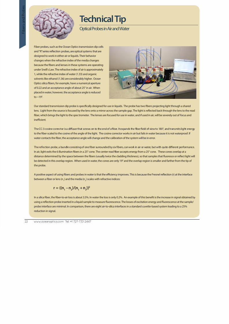
Technical TipOptical Probes in Air and Water
Fiber probes, such as the Ocean Optics transmission dip cells
and “R” series reflection probes, are optical systems that are
designed to work in either air or liquids. Their behavior
changes when the refractive index of the media changes
because the fibers and lenses in these systems are operating
under Snell’s Law. The refractive index of air is approximately
1, while the refractive index of water (1.33) and organic
solvents like ethanol (1.36) are considerably higher. Ocean
Optics silica fibers, for example, have a numerical aperture
of 0.22 and an acceptance angle of about 25° in air. When
placed in water, however, the acceptance angle is reduced
to ~19°.
Our standard transmission dip probe is specifically designed for use in liquids. The probe has two fibers projecting light through a shared
lens. Light from the source is focused by the lens onto a mirror across the sample gap. The light is reflected back through the lens to the read
fiber, which brings the light to the spectrometer. The lenses are focused for use in water, and if used in air, will be severely out of focus and
inefficient.
The CC-3 cosine corrector is a diffuser that screws on to the end of a fiber. It expands the fiber field of view to 180°, and transmits light energy
to the fiber scaled to the cosine of the angle of the light. The cosine corrector works in air but fails in water because it is not waterproof. Ifwater contacts the fiber, the acceptance angle will change and the calibration of the system will be in error.
The reflection probe, a bundle consisting of one fiber surrounded by six fibers, can work in air or water, but with quite different performance.
In air, light exits the 6 illumination fibers in a 25° cone. The center read fiber accepts energy from a 25° cone. These cones overlap at a
distance determined by the space between the fibers (usually twice the cladding thickness), so that samples that fluoresce or reflect light will
be detected in this overlap region. When used in water, the cones are only 19° and the overlap region is smaller and farther from the tip of
the probe.
A positive aspect of using fibers and probes in water is that the efficiency improves. This is because the Fresnel reflection (r) at the interface
between a fiber or lens (n1) and the media (n
2) scales with refractive indices:
r = ((n1 – n
2)/(n
1 + n
2))2
In a silica fiber, the fiber-to-air loss is about 3.5%. In water the loss is only 0.2%. An example of this benefit is the increase in signal obtained by
using a reflection probe inserted in a liquid sample to measure fluorescence. The losses of excitation energy and fluorescence at the sample/
probe interface are minimal. In comparison, there are eight air-to-silica interfaces in a standard cuvette-based system leading to a 25%
reduction in signal.