- o Océ VarioPrint® 6000 Ultra Line Experience ultra speed User manual Operating information

Welcome message from author
This document is posted to help you gain knowledge. Please leave a comment to let me know what you think about it! Share it to your friends and learn new things together.
Transcript

-
o
OcéVarioPrint® 6000Ultra Line
Experience ultra speed
User manualOperatinginformation

Copyright
© 2006-2011, OcéAll rights reserved. No part of this work may be reproduced, copied, adapted, or transmittedin any form or by any means without written permission from Océ.
Océ makes no representation or warranties with respect to the contents hereof and specifi-cally disclaims any implied warranties of merchantability or fitness for any particular purpose.Furthermore, Océ reserves the right to revise this publication and to make changes fromtime to time in the content hereof without obligation to notify any person of such revisionor changes.
Edition: 07-2011

Contents
Chapter 1Preface.................................................................................................................7
Trademarks.................................................................................................8Notes for the reader...................................................................................9... and Training?........................................................................................11Online support for your product.............................................................12
Chapter 2Introduction.......................................................................................................15
Introduction to the Océ VarioPrint® 6000 Ultra Line.............................16Available documentation.........................................................................17
Chapter 3Power information............................................................................................19
The power modes....................................................................................20Turn on the machine................................................................................23Shut down the machine...........................................................................24
Chapter 4Overview of the system components.............................................................25
Introduction to the main system components.......................................26The operator panel...................................................................................28The operator attention light....................................................................31The output locations................................................................................33The paper modules..................................................................................36
Chapter 5Working with the operator panel....................................................................39
Introduction...............................................................................................40The dashboard....................................................................................40
The Schedule view...................................................................................43Introduction to the 'Schedule' view..................................................43Load the media...................................................................................47Load media via the 'Schedule' view.................................................49Instructions for printing to the stacker/stapler (iMFS).....................51Stop a job............................................................................................52
The Jobs view...........................................................................................55Introduction to the 'Jobs' view..........................................................55Schedule a waiting job for printing..................................................63Reprint a job........................................................................................64Give priority to a print job.................................................................65
3
Contents

Print an urgent job immediately.......................................................66Delete print jobs.................................................................................67Print a scheduled job later.................................................................69Make a proof.......................................................................................70Print a job ticket..................................................................................71Bundle jobs in the list of 'Waiting jobs' ...........................................72Select more than one job for printing..............................................74Checking and changing the job properties......................................76
Contradiction handling.................................................................76Change the number of sets..........................................................77Check the first set.........................................................................78Change the page range you want to print..................................80Enable the separator sheets........................................................81Rename a job................................................................................82Change the stacking method per job..........................................83Change '2-sided' into '1-sided' and vice versa...........................84Shift the image in the document printing mode........................85Change the print delivery settings..............................................87Change the number of staples....................................................90Punch or fold the output..............................................................91Select a different media for a job................................................94Enable or disable the use of trailer pages..................................95
The Trays view.........................................................................................96Introduction to the 'Trays' view........................................................96Assign the media to a paper tray......................................................99
Use hotfolders........................................................................................101Introduction to hotfolders................................................................101Activate the hotfolder function........................................................102Create a hotfolder.............................................................................103Create a shared network folder on a workstation..........................104Create a hotfolder default ticket ('default_ticket.jdf').....................106
The System view....................................................................................107The Printer section...........................................................................107
Introduction to the 'Printer' section..........................................107Check the status of the toner reservoirs...................................109Check the status of the staple cartridges..................................111Check the status of the puncher waste box..............................113
The Maintenance section.................................................................114Introduction to the 'Maintenance' section................................114Reset the day counters...............................................................116Find the meter readings.............................................................118
The Setup section.............................................................................119Introduction to the 'Setup' section............................................119Work with the workflow profiles...............................................121
4
Contents

Change the language.................................................................126Change the warning time...........................................................128Truncate the job name...............................................................129Change the advanced media settings.......................................130Make an intermediate check print.............................................134Change a number of settings in the Settings Editor via the oper-ator panel....................................................................................136
The Media section............................................................................139Introduction to the 'Media' section...........................................139Introduction to the media handling..........................................141Add temporary media to the 'Media catalog' .........................143Perform a media registration for standard-size media...........145Perform a media registration for large media..........................152
The Transaction section (optional).................................................159Introduction to the 'Transaction' section .................................159Error handling and output recovery..........................................163Activate the transaction printing function................................168Shift the image in the transaction printing mode....................170Handle the media messages......................................................172Create a transaction setup.........................................................175
Chapter 6Optional finishers and other devices............................................................179
iXDP (integrated eXchangeable Die Punch) - VarioPrint® 6160 only..180Introduction.......................................................................................180
Introduction.................................................................................180Operating information.....................................................................182
Main parts...................................................................................182Die sets available........................................................................185Empty the chip tray....................................................................187Replace a die set.........................................................................189
Service information..........................................................................191Inspect the die sets.....................................................................191Lubricate the die sets.................................................................193Troubleshooting.........................................................................195Specifications..............................................................................199
iP&F (integrated Puncher & Folder) .....................................................200Introduction.......................................................................................200
Introduction.................................................................................200Operating information.....................................................................212
Main parts...................................................................................201Output locations.........................................................................203Empty the waste box..................................................................205Clear a paper jam........................................................................207
5
Contents

Puncher replacement.......................................................................221Replace the puncher...................................................................221Specifications..............................................................................227
Form Assist Module...............................................................................229Form Assist Module.........................................................................229
EasyLift....................................................................................................231EasyLift..............................................................................................231
Remote viewer........................................................................................233Remote viewer..................................................................................233
7" x 10" Statement Size Support...........................................................2357" x 10" Statement Size Support.....................................................235
Chapter 7Keeping the printer running..........................................................................237
Add toner................................................................................................238Finisher: Add staples..............................................................................240Stacker/stapler (iMFS): Replace the staple cartridge...........................246Troubleshooting.....................................................................................247
Appendix AMiscellaneous..................................................................................................251
Product specifications............................................................................252
6
Contents

Chapter 1Preface

Trademarks
List of trademarks
Océ, VarioPrint, PRISMAaccess, PRISMAprepare, PRISMAproduction and DPlink areregistered trademarks of Océ-Technologies B.V.Xerox, DocuTech, DigiPath and FreeFlow are registered trademarks of Xerox Corporation.Adobe and PostScript are registered trademarks of Adobe Systems Incorporated.
Products in this publication are referred to by their general trade names. In most, if notall cases, these designations are claimed as trademarks or registered trademarks of theirrespective companies.
Chapter 1 - Preface8
Trademarks

Notes for the reader
Introduction
This manual helps you to use the Océ VarioPrint® 6000 Ultra Line. The manual containsa description of the product and guidelines to use and operate the Océ VarioPrint® 6000Ultra Line.
Definition
Attention-Getters
Parts of this manual require your special attention. These parts can provide the following:• Additional general information, for example, information that is useful when you
perform a task.• Information to prevent personal injuries or property damage.
Warning, Caution and Note
The words Warning, Caution and Note draw your attention to important information.
Overview of the attention-getters#
IndicatesIconWord
Ignoring this warning could cause serious injury oreven death.The Warning indication has several icons that warnagainst various hazards. The icons are shown below.
Warning
General hazardWarning
Hot surfaceWarning
Electric shockWarning
Moving partsWarning
Laser beamWarning
Chapter 1 - Preface 9
Notes for the reader

IndicatesIconWord
Ignoring this warning could cause injury or damage toproperty.
Caution
Indicates additional important information.Note
The use of heat-resistant gloves is mandatory when youcarry out these actions.
Safety information
Before using this Océ product, make sure that you read and understand the safety infor-mation which is part of the user documentation. You can download the safety informationvia http://global.oce.com/support/ or, if applicable, find it on the user documentationCD/DVD that is delivered together with the machine or obtain the safety informationfrom your local Océ representative. To avoid potential hazards, maintenance is strictlypreserved to properly qualified and trained service technicians.
Chapter 1 - Preface10
Notes for the reader

... and Training?
Océ Education services
Knowledge is power. Especially when it comes to document workflow. Océ Educationservices systematically transfer our expert knowledge to your employees.
Our proven training methods give you insight that allows you to maximize results fromall your Océ hardware and software.And they lead to improved cost control, productivity and quality, as well as faster returnon your investment.
For more information about Océ Education Servicesdownload the Océ Education services brochure at http://global.oce.com/services/profes-sional-services/education-services
Chapter 1 - Preface 11
... and Training?

Online support for your product
Introduction
Océ offers comprehensive support for your product on the website:http://global.oce.com/Here you can find the latest information that can help you to take full benefit of yourproduct. You can also find answers to your questions.
Please visit the website regularly for updates on the following topics:• Downloads:• Support• Supplies
Downloads:
User manuals, printer drivers and other resources can change without prior notice. Tostay up-to-date, you are advised to download the latest resources from:http://global.oce.com/supportBefore using your product, you must always download the latest safety information foryour product. Before using your product, make sure that you read and understand allsafety information in the manual entitled "Safety Instructions".
Support
A Knowledge Base (OKB) with answers to your questions or problems is continuouslybeing updated. To find an answer to your question or problem, please visit:http://global.oce.com/support and select your product.In the Support section, use the search field to enter your question. You will get a list ofpossible answers.
Supplies
A media guide with the latest information is available on the website:http://global.oce.com/supplies/
Here you can find the media that your product supports, for example. You can also findmore information about supplies for your product, such as toner. You can also order newsupplies directly through the website.
Chapter 1 - Preface12
Online support for your product

Addresses of local Océ organizations
For the addresses of local Océ organizations, visit:http://global.oce.com/contact/countries
Comments
Send your comments by e-mail to:[email protected]
Chapter 1 - Preface 13
Online support for your product

Chapter 1 - Preface14
Online support for your product

Chapter 2Introduction

Introduction to the Océ VarioPrint® 6000 Ultra Line
Introduction
The Océ VarioPrint® 6000 Ultra Line is a series of high-volume, cut-sheet printers. Themachines are intended for both document printing and stream printing.The key feature of the machine is the Océ Gemini Instant Duplex Technology. Thistechnology enables the machine to print the front side and back side of a sheet at thesame time. Depending on your version, the sustained print speed, including recondition-ing, ranges from 170, 200, 250 to 314 images per minute (A4 / Letter) when you printa 2-sided document.The print speed for 1-sided documents (A4/Letter) ranges from 125 images per minuteto 157 images per minute (Océ VarioPrint® 6320 only).This section gives a short description of the main features of the machine.
Note:Not all the configurations mentioned in this user manual are available worldwide. Pleasecontact your local dealer for the available configurations in your country.
Overview of the main features• Océ Gemini Instant Duplex Technology that enables the printing on both sides of a
sheet at the same time.• Advanced scheduling concept on the operator panel to keep the machine running.• Load and assign the media while the machine prints.• Support of up to 12 paper trays (total input capacity up to 13,800 sheets) and a roll
feeder.• Support of up to 3 stackers, a finisher, a stacker/stapler and other external finishers.• Support of a large range of media, media sizes and media weights.• Support of PS/PCL/PDF and streaming PS.• Support of a large range of software products, for example the Océ PRISMA series,
Xerox® DigiPath® and Xerox® FreeFlow® Makeready, Kodak® KDK Link.• Support of RDO files via Océ DP Link.• Support of a direct copy path from the optional Océ DS60 scanner to the printer.
Chapter 2 - Introduction16
Introduction to the Océ VarioPrint® 6000 Ultra Line

Available documentation
Introduction
This machine is delivered with the following items:• A 'Documentation and Driver Notice'• A 'Safety Information Sheet'.
Note:Please check www.oce.com for the latest version of the documentation.
Main Content of the User Manuals
The following table provides an overview of the main content of the user manuals.
Main Content of the User Manuals#
Main contentUser Manual
• Overview of the main system components• Working with the operator panel• Handling and managing jobs on the operator panel• Optional finishers and other devices• Add media, toner and staples
Operating informa-tion
• Replacing parts• Cleaning parts• Solve a paper jam in the engine module
Maintenance tasks
• Instructions for safe useSafety information
Chapter 2 - Introduction 17
Available documentation

Chapter 2 - Introduction18
Available documentation

Chapter 3Power information

The power modes
Introduction
This section describes the power switches and the main power modes of the machine.The table in this section describes, among other things, the low-power mode and thesleep mode. These modes are energy-saving modes. You can set the timers for these modesin the Settings Editor on the controller. Furthermore, you can set a calendar timer in theSettings Editor. Then the machine will wake up from the sleep mode at the indicatedtime. You can use the calendar timer for example to make sure that the machine is readyfor use at the beginning of your working day. The machine can warm up before you startyour working day. Please refer to the online help on the Settings Editor for more infor-mation about these timers.
Description of the power switch and the On/Off button
The machine has the following switch and button to control the power supply.• Power switch
The power switch is located at the back side of the machine. The power switch connectsand disconnects the machine to the mains power.
• On/Off button with amber and green LEDs .The On/Off button on the machine ‘Introduction to the main system components’ onpage 26 allows you to toggle between the stand-by mode and the sleep mode. This isonly possible if the power switch is in the '1' position and the start-up phase iscompleted.
Description of the main power modesThe main power modes#
Status of theHold button and Releasebutton
Status of theOn/Off button
DescriptionPower mode
OffOffThe machine is completely off.The power switch is in the 'O'position. There is no powerconsumption. The machinecannot receive or print jobs.
Off
Chapter 3 - Power information20
The power modes

Status of theHold button and Releasebutton
Status of theOn/Off button
DescriptionPower mode
OffBlinking am-ber
Stage 1: After you put the powerswitch in the 'I' position, butbefore you press the On/Offbutton .
Starting up(divided into 2stages)
OnContinuousgreen
Stage 2: After you press theOn/Off button .
OnContinuousgreen
The machine is ready to printjobs.
Stand-bymode
OnContinuousgreen
The machine is busy.Run mode
OnContinuousgreen
The machine automatically en-ters the low-power mode whenthe machine has been in thestand-by mode for a definedtime and no button was touched.The machine wakes up when ajob arrives in the list of 'Sched-uled jobs' or when you touch abutton. The machine will startto warm up.
Low-powermode
OnBlinking am-ber
The machine is preparing to gointo sleep mode.
Going intosleep mode
Chapter 3 - Power information 21
The power modes

Status of theHold button and Releasebutton
Status of theOn/Off button
DescriptionPower mode
OffContinuousamber
The machine automatically goesfrom the low-power mode intothe sleep mode after a definedtime.You can also place the machineinto the sleep mode manually.Press the On/Off button to dothis. The machine will enter thesleep mode as soon as the list of'Scheduled jobs' is empty.The machine will wake up fromthe sleep mode when you pressthe On/Off button or whenthe calendar timer expires. Themachine will also wake up whena printable job arrives in the listof 'Scheduled jobs', providedthat the function 'Automaticwake-up' in the Settings Editoris enabled.
Sleep mode
Chapter 3 - Power information22
The power modes

Turn on the machine
Introduction
This section describes how to turn on the machine when it is completely off.
Note:When the machine is in the sleep mode (see ‘The power modes’ on page 20), you mustpress the On/Off button to wake up the machine.
Turn on the machine
1. Put the power switch at the back of the machine in the 'I' position.The On/Off button blinks amber while the machine and the controller start up.Wait until the operator panel asks you to press the On/Off button .
2. Press the On/Off button .The On/Off button remains green.The machine warms up.
Chapter 3 - Power information 23
Turn on the machine

Shut down the machine
Introduction
This section describes how to shut down the machine completely, for example for theholidays.
Note:If you want to put the machine into the sleep mode manually (see ‘The power modes’ onpage 20), for example at the end of a working day, you must press the On/Off button
. Then the machine will go into the sleep mode as soon as the list of 'Scheduled jobs'is empty. When the machine is in the sleep mode, the On/Off button is continuousamber.
Shut down the machine
1. On the operator panel, press the 'System' button.2. Touch the 'Setup' button.3. Touch the 'Shut down system' button in the 'User interface' section.
A dialog box asks you to confirm that you really want to shut down the machine.4. Press 'Yes'.
A message indicates when the shutdown will begin. Wait until the following has happened.• The Hold button and the Release button are off• The On/Off button blinks amber• The screen of the operator panel is off.
5. Put the power switch at the back of the machine in the 'O' position.
Chapter 3 - Power information24
Shut down the machine

Chapter 4Overview of the systemcomponents

Introduction to the main system components
Introduction
The following illustration shows the main system components. The table describes themain components. Please follow the links in the table for comprehensive information.
1
2
3
4
3
1
2
5 6 74 9
8
[10] The main system components
The main system componentsThe main system components#
FunctionComponent
The operator panel helps you with your dailywork, for example the scheduling of the jobs.Furthermore, the operator panel helps you to solveerrors or perform maintenance tasks (see ‘The op-erator panel’ on page 28).
Operator panel1
The operator attention light enables you to checkthe status of the system from a distance (see ‘Theoperator attention light’ on page 31).
Operator attentionlight
2
A roll feeder is an optional device that adds paperinput capacity to your printer. When you use aroll feeder, you can only use 1 or 2 paper modules.A combination of 3 paper modules and a rollfeeder is not possible. The operator panel displaysthe roll feeder and gives feedback about the statusof the roll feeder. For example whether the roll isfull or empty. Please refer to the documentationof the roll feeder manufacturer for more informa-tion, for example about replacing an empty roll.
Roll feeder (option-al)
3
Chapter 4 - Overview of the system components26
Introduction to the main system components

FunctionComponent
The paper module contains 4 paper trays. Thepaper trays contain the media that will be printed.The default configuration of the system contains1 paper module. You can add 1 or 2 more papermodules to the default configuration to increasethe media input capacity (see ‘The paper modules’on page 36).
Paper module4
The engine module contains the components thatprint the media. Access to the engine module isonly required when a paper jam occurs or whenmaintenance is required. The doors at the left-handside and right-hand side of the engine module giveaccess to the toner units.
Engine module5
The puncher (iXDP) can make holes in the prints.The number of holes depends on the die set thatis installed (see ‘Replace a die set’ on page 189).
Puncher (optional)6
The stacker is the output location of a defaultconfiguration. The system supports up to 3 stack-ers (see ‘The output locations’ on page 33).
Stacker7
The finisher on top of the stacker is an optionaloutput location for the print jobs. The finisher canstaple the jobs (see ‘The output locations’ on page33).
Finisher (optional)8
The stacker/stapler (iMFS) is an optional outputlocation for the print jobs (see ‘The output locations’on page 33). The stacker/stapler supports a largenumber of media sizes.
Stacker/stapler (op-tional)
9
Chapter 4 - Overview of the system components 27
Introduction to the main system components

The operator panel
Introduction
The operator panel is a touch screen panel. You must touch the buttons on the operatorpanel to access the various functions. The operator panel is divided into 4 main views.The taskbar at the bottom of the screen contains the buttons that give access to the 4main views. Furthermore, the operator panel has 2 hardkeys ( and ) at the bottom ofthe panel.This section gives an overview of the main keys and buttons of the operator panel.
Note:You can clean the screen of the operator panel with a 50% mix of water and isopropylalcohol (K2). Use a lint-free cloth. Always put the cleaner onto the cloth and not directlyon the screen.
Chapter 4 - Overview of the system components28
The operator panel

Illustration
1 2
3 4 5 6
[11] The operator panel
The main components of the operator panelThe main components of the operator panel#
FunctionComponent
• Put the machine on hold• Stop printing after a set• Stop printing as soon as possible ‘Stop a
job’ on page 52.
Hold key 1
Chapter 4 - Overview of the system components 29
The operator panel

FunctionComponent
• Allow the machine to print• Resume printing when the machine is on
hold.
Note:In the dashboard a softkey is availablewith the same functionality.
Release key 2
Access the 'Schedule' view ‘Introduction to the'Schedule' view’ on page 43.
'Schedule' button3
Access the 'Jobs' view ‘Introduction to the 'Jobs'view’ on page 55.
'Jobs' button4
Access the 'Trays' view ‘Introduction to the'Trays' view’ on page 96.
'Trays' button5
Access the 'System' view‘Introduction to the 'Printer' section’ on page107‘Introduction to the 'Maintenance' section’ onpage 114‘Introduction to the 'Setup' section’ on page 119‘Introduction to the 'Media' section’ on page 139
'System' button6
Chapter 4 - Overview of the system components30
The operator panel

The operator attention light
Introduction
The operator attention light informs you about the status of the machine. To improvethe productivity, the operator attention light can warn you some time before the machinestops. You can set the warning time on the operator panel ‘Change the warning time’ onpage 128.The operator attention light contains 3 lights (red, orange and green) that indicate thecurrent status of the machine. The colors of the lights match the status that is currentlyindicated on the operator panel. For example, when operator interaction is required soon,both the dashboard ‘The dashboard’ on page 40 and the operator attention light willdisplay an orange warning. The dashboard displays a message with the required action.This section describes the meaning of the colors of the operator attention light.
[12] The operator attention light
Status colorsThe colors of the operator attention light#
DescriptionColor
The machine has stopped, for example because a requiredmedia type is not available or an error has occurred.Operator attention is required now.
Red
The machine will stop soon, for example because an outputlocation is almost full. The orange light lights up when themachine reaches the warning time.Operator attention is required soon.
Orange
Chapter 4 - Overview of the system components 31
The operator attention light

DescriptionColor
The machine is busy printing. The machine can printlonger than the defined warning time.Operator attention is not required.
Green
The machine is idle. There are no jobs scheduled forprinting.
All lights off
Chapter 4 - Overview of the system components32
The operator attention light

The output locations
Introduction
The machine supports several output locations for the printed jobs. The default configu-ration of your machine contains a stacker and the system output. The finisher and thestacker/stapler are optional output locations. Furthermore, you can connect several op-tional external finishers to the machine.
Note:You need the optional finisher, the optional stacker/stapler or another optional externalfinisher to staple the jobs.
Illustration
3
1
2
4
6
5
[13] The output locations
Overview of the output locationsDescription of the output locations#
DescriptionComponent
The stacker is the default output location of the machine. Thestacker capacity is 6,000 sheets, in 2 stacks of 3,000 sheets each(80 g/m² or 20 lb. bond).The stacker does not contain staple cartridges. Therefore, thestacker cannot be the output location for jobs that require sta-ples.
'Stacker'1
Chapter 4 - Overview of the system components 33
The output locations

DescriptionComponent
The system output is the output location for the followingprints.• Error prints• Sample prints• Configuration reports• Job tickets• The test sheets for the media registration.
Make sure that you regularly remove the sheets from the systemoutput.
'System out-put'
2
The optional finisher contains the following output trays.• 3 output trays• 1 upper output (see no. 4 below)
The finisher contains 2 staple cartridges to staple the jobs. The3 output trays can receive A4, Letter and similar media sizes.Stapled jobs (A4, Letter and similar media sizes only) go intothe output trays. The total capacity of the output trays is 3,700sheets (80 g/m² or 20 lb bond).
Note:The output trays cannot receive tab sheets.
'Finisher' (op-tional)
3
The finisher upper output is part of the finisher. The upperoutput can receive all formats. However, the upper output ismainly intended for large media or jobs with mixed size media.The maximum capacity of the upper output is 500 sheets (80g/m² or 20 lb bond).
Note:The upper output does not contain staple cartridges.Therefore, the upper output cannot be the output loca-tion for jobs that require staples.
'Finisher up-per output'
4
Chapter 4 - Overview of the system components34
The output locations

DescriptionComponent
The optional stacker/stapler contains 1 staple cartridge to staplethe jobs. The staple cartridge can staple your document with 1or 2 staples. The stacker/stapler can stack and staple variousmedia sizes. The device supports the stapling of mixed mediasizes, as long as the width of the media is the same. The capacityof the lower tray is 2,000 sheets (80 g/m² or 20 lb bond).
Note:The stacker/stapler does not support the stapling of tabsheets.
'Stacker/sta-pler'(iMFS) -optional
5
The upper output is the upper tray of the stacker/stapler. Thecapacity of the upper output is 250 sheets (80 g/m² or 20 lbbond).
'Stacker/sta-pler upper out-put'
6
Chapter 4 - Overview of the system components 35
The output locations

The paper modules
Introduction
The paper trays contain the media that are required for the print jobs. The default con-figuration of the machine contains 1 paper module with 4 paper trays. You can add 1 or2 more paper modules to the machine. Then the total number of paper trays is extendedto 8 or 12 respectively. You can find more information about the capacities of the papertrays and the supported media size in the appendix of this manual.This section describes the control panel on each paper module.
Note:You can use the control panel on the paper modules to open the paper trays and loadthe media. However, the recommended way to open the paper trays and assign the mediais via the 'Schedule' view. You can also open the paper trays and/or assign the media viathe 'Trays' view (see‘Assign the media to a paper tray’ on page 99).
Illustration
1
2
3
4
1
2
3
4
1 3
2
5
4
[14] The control panel on the paper modules
The control panel
Each paper module contains a control panel next to the upper paper tray. The controlpanel consists of 4 sections that correspond with the 4 paper trays. Each section displaysthe current filling level of the corresponding paper tray. Furthermore, the control panelindicates whether the media in the paper tray is assigned or not. The following table de-scribes the various parts of the control panel.
Chapter 4 - Overview of the system components36
The paper modules

The parts of the control panel#
DescriptionNumber
The LEDs indicate the current amount of sheets in the correspond-ing paper tray. Each lit-up LED indicates the presence of about 100sheets (based on media of 80 g/m2 or 20 lb bond).
1
Press the button to open the corresponding paper tray. You canonly open 1 paper tray at a time.
2
When the check mark is green, the media in the paper tray is defined.The system knows which media is in the paper tray.
3
When the arrows are red, the media in the paper tray is not defined.The system does not know which media is in the paper tray. The'Trays' view on the operator panel indicates that no media is assignedto the paper tray.
4
The 'Not assigned' button. This button applies to the paper traywhere you just put the media.You can press the 'Not assigned' button when you load a new mediatype into a paper tray without defining this media type on the oper-ator panel first. Then the printer cannot accidentally use the mediain this paper tray before the media is correctly defined on the oper-ator panel. You can define the media type in the 'Trays' view on theoperator panel later (see ‘Assign the media to a paper tray’ on page99).
Note:Make sure that the paper tray is open when you press the'Not assigned' button.
5
Chapter 4 - Overview of the system components 37
The paper modules

Chapter 4 - Overview of the system components38
The paper modules

Chapter 5Working with the operatorpanel

Introduction
The dashboard
Introduction
The dashboard is the upper blue part of the operator panel. The dashboard is always visible,irrespective of the current view ‘The operator panel’ on page 28. The dashboard gives thefollowing feedback.• The status of the system• The current process• Instructions for the operator• The status of the supplies• The status of the external finisher, if applicable• Whether maintenance is required.• The 'Resume' button after you stopped the printer.
Illustration
The following illustration shows the dashboard while the machine is busy. The verticalstatus bar is green. No action is required.
[15] The dashboard - No action is required
The following illustration shows the dashboard while the machine is busy. The verticalstatus bar is orange. Next to the status bar, the dashboard displays a message that indicateswhich action is required soon.
[16] The dashboard - Action is required soon
The parts of the dashboardThe dashboard#
FunctionNumber
Display the status of the machine, for example 'Initializing...','Printing...' or 'Printing will stop...'. Each status message canhave a sub-message with additional information.
1
Chapter 5 - Working with the operator panel40
The dashboard

FunctionNumber
Display the file name of the current job (for document printing)or current stream (for stream printing). Furthermore, theprogress of the current job is displayed.For document printing, the counter can display the followinginformation.• Set X of Y• Sheet X of Y or Sheet X.
X represents the current status of the print job. Y represents thetotal number of sets or sheets of a print job.When the sorting method for a job is set to 'By set', and a setcontains at least 40 pages, then the dashboard displays the setcount (Set X of Y) and the sheet count (Sheet X of Y) for theset. If a set contains less than 40 pages, then the dashboard onlydisplays the set count (Set X of Y).If the sorting method for a job is set to 'By page', or when youprint stream jobs, the dashboard only displays a sheet count.
2
Display the action that you must do now or soon. The colorsof the vertical status bar at the left-hand side match the colorsof the operator attention light ‘The operator attention light’ onpage 31. When the color is orange or red, a message indicatesthe required action.Orange means that action is required soon. How long beforean upcoming action the operator panel starts to display themessage depends on the defined warning time ‘Change thewarning time’ on page 128.Red means that action is required now.
Note:The operator panel can only display one message at atime. When there are more messages, the operatorpanel displays the first required or most importantmessage.
3
Chapter 5 - Working with the operator panel 41
The dashboard

FunctionNumber
• Display the status of the external finisher, if applicable.• Display the status of the staple cartridges ‘Check the status of
the staple cartridges’ on page 111.• Display a warning that maintenance is required. When
maintenance is required soon, the maintenance icon becomesorange . When maintenance is required now, the mainte-nance icon becomes red .
• Display the status of the toner reservoirs ‘Check the status ofthe toner reservoirs’ on page 109.
Note:Only key operators who received the special mainte-nance training are allowed to do maintenance tasks.
4
Chapter 5 - Working with the operator panel42
The dashboard
The Schedule view
Introduction to the 'Schedule' view
Introduction
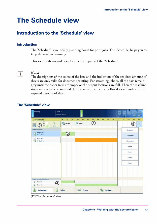
The 'Schedule' is your daily planning board for print jobs. The 'Schedule' helps you tokeep the machine running.
This section shows and describes the main parts of the 'Schedule'.
Note:The descriptions of the colors of the bars and the indication of the required amount ofsheets are only valid for document printing. For streaming jobs , all the bars remaingrey until the paper trays are empty or the output locations are full. Then the machinestops and the bars become red. Furthermore, the media toolbar does not indicate therequired amount of sheets.
The 'Schedule' view
[17] The 'Schedule' view
Chapter 5 - Working with the operator panel 43
Introduction to the 'Schedule' view

1. The jobs pane
The jobs pane shows the jobs on a timeline. The width of the job corresponds to the(remaining) print time. A vertical line separates the jobs. The vertical line moves to theleft as the printing of a job progresses.An icon and the job name represent a job. The icon indicates the state of the job, for ex-ample printing .Furthermore, the icon indicates the stop moments of the machine. For example, whenthe setting 'Confirm start of job' in the workflow profiles (see list of references below) isset to 'On' or when you use the 'Stop after job' function.
2. The 'Required media' pane
The 'Required media' pane displays the media that are required for each scheduled job.For each required media, the media properties are displayed (see list of references below).The bars show the availability of the media. The bars can have the following colors.
The colors of the bars#
DescriptionColor of the bar
The required media is available.Green
The media is required in the future, but not available then. Forexample because the paper trays do not contain sufficient sheetsof the required media.
Orange
The system cannot determine the exact number of sheets thatis available in the paper trays.
Yellow
The media is required now, but not available. The job can onlystart when you load the required media.
Red
When you print small jobs, the bars for these jobs may not be completely visible. Toprevent that you do not see the status of these small jobs, the operator panel can showthe following images.
#
NOTEWhen you set the zoom control (5) to a shorter time-scale, in most cases the operatorpanel will display bars for these small jobs.
The possible display of small jobs#
DescriptionImage
Green. The required media is available.
Chapter 5 - Working with the operator panel44
Introduction to the 'Schedule' view

DescriptionImage
Orange. The media is required in the future, but not availablethen. For example because the paper trays do not contain suffi-cient sheets of the required media.
Red. The media is required now, but not available. The job canonly start when you load the required media.
3. The media toolbar
The media toolbar displays the following information for the media that is selected inthe 'Required media' pane. Furthermore, the media type toolbar contains the 'Load'button to load and assign the required media.
The icons in the media toolbar#
DescriptionIcon
The list of 'Required media' shows the required media for thescheduled jobs. When the paper module indicator is completelygrey, this means that not one of the required media is availablein the paper trays.
The list of 'Required media' shows the required media for thescheduled jobs. When a paper tray is highlighted in green, thehighlighted paper tray contains a media that is required by oneof the scheduled jobs.
The list of 'Required media' shows the required media for thescheduled jobs. When a paper tray is highlighted in blue, thehighlighted paper tray contains the media that is also highlightedin blue in the list of 'Required media'.
4. The output locations pane
The output locations pane displays the output locations that are required for the scheduledjobs. The bars show the availability of the output locations. The bars can have the followingcolors.
The colors of the bars#
DescriptionColor of the bar
The output location is required and available.Green
The output location is required in the future, but not availablethen. For example, because the output location will be full soon.
Orange
Chapter 5 - Working with the operator panel 45
Introduction to the 'Schedule' view

DescriptionColor of the bar
The output location is required now, but not available. For ex-ample, because the output location is full.
Red
The output location is required, but availability is unknown.Gray
5. The zoom control
The zoom control enables you to adjust the time scale visible in the 'Schedule'. Whenyou press the zoom button, a drop-down list appears. Then you can select the desiredtime scale.
Chapter 5 - Working with the operator panel46
Introduction to the 'Schedule' view

Load the media
Introduction
This section describes how to load the media into a paper tray.When you load the media via the 'Load' button in the 'Schedule', the paper tray is auto-matically assigned to the correct media.When you load and assign the media via the 'Assign' button in the 'Trays' view, you mustassign the paper tray to the loaded media manually.
When no external finisher is connected to the machine, you must put all the media typesface up and header up into the paper trays. The tabs of tab sheets must be at the right-hand side. When an external finisher is connected to the machine, it is possible that youmust put the media into the paper trays in a different way. Refer to the documentationof the external finisher for more information about how to place the media.
When to do• The 'Schedule' displays a red bar next to a required media. The red bar indicates that
a scheduled job now requires a media that is not available in the paper trays.• The 'Schedule' displays an orange bar next to a required media. The orange bar indi-
cates that a scheduled job requires media which is either not available in the papertrays or which is available, but not in sufficient quantity to finish the job.
• The current job requires more of the same media than is currently loaded in the papertrays. You can add more of the required media into another paper tray.
• You already want to load and assign media that are required for the next job (workahead).
Caution:Always put the stack of media aligned with the left-hand side of the paper guides insidethe paper trays, as indicated on the sticker inside the paper trays.
Illustration
SR
SR
[24] The sticker inside the paper trays indicates how to load the media
Chapter 5 - Working with the operator panel 47
Load the media

Load the media
1. Put a small stack of media into the paper tray.2. Press the green handle on the right-hand guide and push the guide against the edge of
the media.3. Turn the green knob to adjust the front guide and the rear guide.4. Put the rest of the media on top of the small stack.
Note:If you want to assign the media later you must press the 'Not assigned' button ‘The papermodules’ on page 36, as indicated on the right-hand side of the sticker.
Chapter 5 - Working with the operator panel48
Load the media

Load media via the 'Schedule' view
Introduction
When the 'Schedule' view is available on your printer, you can load and assign the requiredmedia directly in the 'Schedule' section.
Note:When you load a different media size, you must also set the paper guides inside the papertray to the correct dimensions.
Illustration
[25] Load the media
How to load and assign media via the 'Schedule' view
1. Touch the button for the media you want to load, for example Special A4.2. Press 'Load'.
The 'Trays' view appears.3. On the screen, touch the paper tray where you want to load the media.
Chapter 5 - Working with the operator panel 49
Load media via the 'Schedule' view

4. Touch 'OK' to open the paper tray.5. Load the media into the paper tray.
The system assumes you loaded the selected media type, in this example Special A4. Thesystem will automatically assign Special A4 to that paper tray.
Note:You can always change the assigned media type later by touching the 'Assign' button.
6. Gently close the paper tray.
•Introduction to the Schedule view, on page 43
Chapter 5 - Working with the operator panel50
Load media via the 'Schedule' view

Instructions for printing to the stacker/stapler (iMFS)
Introduction
Note:This section only applies to the use of oriented media and tab sheets in combinationwith the optional stacker/stapler (iMFS).
The machine supports oriented media. Oriented media are media of which the front sidediffers from the back side. An example of oriented media is media with a company logo.If you use oriented media and print to the optional stacker/stapler, you must place themedia into the paper trays as follows:• Face up and header down (for long-edge feed)
The face of the media, for example a company logo, is visible and point towards thefront of the printer.
• Face up and header to the left (for short-edge feed).The face of the media is visible and points towards the left-hand side of the printer.
This orientation makes sure that the documents are stapled at the correct position.
Special instructions for the use of oriented media
When a job contains oriented media but no tab sheets, you must put this media headerdown into the paper tray. The media must align with the header-down orientation of theprinted images (header down for long-edge feed and header to the right for short-edgefeed).
Special instructions for the use of tab sheets
When a job contains tab sheets, you must do the following.• Put all the oriented media for the job, including the tab sheets, header up and header
to the left (for short-edge feed) into the paper tray.• Temporarily change the default media orientation on the Controller to 'Header-up'.
To do this, you must go to the setting 'Preferences' - 'Print job defaults' - 'Stacker/sta-pler (iMFS)' or 'Stacker/stapler upper output' - 'Header orientation'. There you canclick the radio button for 'Header-up'.
Jobs that contain tab sheets are sent to the stacker/stapler when no stacker is present.When a stacker is present, the jobs are sent to the stacker to improve the stack quality.
Chapter 5 - Working with the operator panel 51
Instructions for printing to the stacker/stapler (iMFS)

Stop a job
Introduction
When the machine is printing a job, you can stop the machine at the following moments.• Stop after a set• Stop after a page• Stop after a job.
The following table gives an overview of the stop behavior of the machine. The proceduresin this section describe how to stop the machine via the operator panel.
Note:You can also interrupt a job by ejecting a stack of sheets from the stacker. When youpress the eject button next to the stacker door 1 time, the stacker ejects the stack whena set is ready. When you press the eject button 2 times, the stacker ejects the stack assoon as possible.
The stop behavior of the machineWhen does the machine stop#
ThenWhen
The machine stops when a set of the ac-tive print job is ready. It depends onthe set size and the moment you press thekey, when the machine will stop. For ex-ample, when you have a large set of 1,000pages and you press the key after the firstpage, the printing will continue for acouple of minutes.
You press the Hold key 1 time
The machine stops as soon as possible(after a page, in most cases within 30seconds).
You press the Hold key 2 times
The machine stops when the selected jobis ready.The 'Jobs' view displays a horizontal redand white stop bar below the selected job.The 'Schedule' view displays a verticalstop bar behind the selected job.
You touch the 'Stop after job' button inthe toolbar of the 'Jobs' view
Chapter 5 - Working with the operator panel52
Stop a job

ThenWhen
The machine stops each time the first setof a print job is ready. You can check thefirst set before you continue the print job.
The 'Check first set' setting in a 'Work-flow profile' is 'On' ‘Work with the work-flow profiles’ on page 121 and this settingis also enabled in the job
The machine stops each time at the startof a job. You must start each job manual-ly.
The 'Confirm start of job' setting in a'Workflow profile' is 'On'
Note:When you print streaming jobs or jobs that consist of 1 large set, you must alwayspress the Hold key 2 times to stop the machine as soon as possible.
Stop after a set
1. Press the Hold key 1 time.The red LED of the Hold key starts to blink.The machine stops when a set of the active print job is ready.
Stop after a page
1. Press the Hold key 2 times.The red LED of the Hold key starts to blink.The machine stops as soon as possible.
Note:The memory of the machine can contain up to 50 pages. Therefore, it is possible forthe machine to print more than a set before the machine stops.
Stop after a job
1. In the list of 'Scheduled jobs' in the 'Jobs' view, touch the job after which the machinemust stop.
2. Press 'Stop after job'.The machine stops as soon as the selected job has been printed. A red and white stop barindicates that the stop-after-job function is active. Touch 'Stop after job' again to removethe stop bar and continue printing.
Chapter 5 - Working with the operator panel 53
Stop a job

Stop a streaming job or transaction stream
1. Press the Hold key 1 time.The red LED of the Hold key starts to blink.The printer will continue to print the pages that are already in the buffer. When thebuffer is empty, the printer stops.
Chapter 5 - Working with the operator panel54
Stop a job

The Jobs view
Introduction to the 'Jobs' view
Introduction
The 'Jobs' view enables you to manage the print jobs on the machine locally. The 'Jobs'view is divided in the 'Queues' and 'Printed jobs' views. This section describes the itemsof both views.
Note:Whether a button is enabled depends on the number of selected jobs and the state ofthe jobs. Not all buttons are available for streaming jobs .
Illustration
[26] The 'Scheduled jobs' view
Chapter 5 - Working with the operator panel 55
Introduction to the 'Jobs' view

The items of the 'Scheduled jobs' view of the 'Jobs' viewDescription of the 'Scheduled jobs' view#
More informationFunctionItem
Display the active print job and the jobs that are scheduledfor printing.
'Scheduled jobs'
Check or change the propertiesof a job. The button is only en-abled when you select 1 job.
Note:You can also press a job2 times to check orchange the properties ofthat job.
'Properties' button
‘Give priority to a printjob’ on page 65
Give priority to a scheduled job.The job is printed when the ac-tive print job is ready. Thebutton is only enabled when youselect 1 job.
'To top' button
‘Stop a job’ on page 52Stop the machine after a selectedjob. The button is only enabledwhen you select 1 job.
'Stop after job' button
‘Delete print jobs’ onpage 67
Delete the selected job of jobs.The button is enabled when youselect 1 or more jobs.
'Delete' button
‘Print a scheduled joblater’ on page 69
Move a job from the list of'Scheduled jobs' to the list of'Waiting jobs'.The button is enabled when youselect 1 or more jobs.
'Move' button
‘Print a job ticket’ onpage 71
Print an overview of the mainjob settings and job parameters.The button is only enabled whenyou select 1 job.
'Ticket' button
Chapter 5 - Working with the operator panel56
Introduction to the 'Jobs' view

More informationFunctionItem
‘Select more than one jobfor printing’ on page 74‘Select more than one jobfor printing’ on page 74
Select a number of jobs at thesame time. You can use one ofthe following:• 'All': select all the jobs in the
list.• 'None': deselect all the jobs
in the list.• 'Invert selection': turn the se-
lected jobs into deselectedjobs, and the other wayround.
• 'Jobs with available media':select all the jobs for whichthe media are currently avail-able in the paper trays.
• 'Jobs with label': select all thejobs with a certain label.
'Select' button
‘Print an urgent job im-mediately’ on page 66
Print an urgent job immediately.The job is printed when thecurrent set of the active print job
is ready. The button is onlyenabled when you select 1 ormore jobs.
'Print now' button
Chapter 5 - Working with the operator panel 57
Introduction to the 'Jobs' view

Illustration
[27] The 'Waiting jobs' view
The items of the 'Waiting jobs' view of the 'Jobs' viewDescription of the 'Waiting jobs' view#
More informationFunctionItem
Display the jobs that are not yetscheduled for printing.
'Waiting jobs'
Check or change the propertiesof a job. The button is only en-abled when you select 1 job.
Note:You can also press a job2 times to check orchange the properties ofthat job.
'Properties' button
Chapter 5 - Working with the operator panel58
Introduction to the 'Jobs' view

More informationFunctionItem
‘Delete print jobs’ onpage 67
Delete the selected job or jobs .The button is enabled when youselect 1 or more jobs.
'Delete' button
‘Bundle jobs in the list of'Waiting jobs' ’ on page72
Bundle: Combine a number ofjobs into 1 job, for example tocreate a set of documents thatare required for a meeting.Split: Split a bundle job into theoriginal jobs.
'Bundle' or 'Split' but-ton
‘Print a job ticket’ onpage 71
Print an overview of the mainjob settings and job parameters.The button is only enabled whenyou select 1 job.
'Ticket' button
‘Select more than one jobfor printing’ on page 74‘Select more than one jobfor printing’ on page 74
Select a number of jobs at thesame time. You can use one ofthe following:• 'All': select all the jobs in the
list.• 'None': deselect all the jobs
in the list.• 'Invert selection': turn the se-
lected jobs into deselectedjobs, and the other wayround.
• 'Jobs with available media':select all the jobs for whichthe media are currently avail-able in the paper trays.
• 'Jobs with label': select all thejobs with a certain label.
'Select' button
Chapter 5 - Working with the operator panel 59
Introduction to the 'Jobs' view

More informationFunctionItem
‘Make a proof’ on page70
Print 1 copy of a job to checkwhether the result of the printjob meets your expectation. Thebutton is only enabled when youselect 1 job.
Note:The proof print is notsubtracted from thenumber of sets you de-fined for this job.
'Proof' button
‘Schedule a waiting jobfor printing’ on page 63
Move a job from the list of'Waiting jobs' to the list of'Scheduled jobs'.The button is enabled when youselect 1 or more jobs.
'Print' button
Illustration
[28] The 'Printed jobs' view
Chapter 5 - Working with the operator panel60
Introduction to the 'Jobs' view

The items of the 'Printed jobs' view of the 'Jobs' viewDescription of the 'Printed jobs' view#
More informationFunctionItem
Display the jobs that were print-ed successfully. The system onlymoves the printed jobs to the listof 'Printed jobs' when the setting'Printed jobs' in the SettingsEditor is enabled.
'Printed jobs'
Check or change the propertiesof a job. The button is only en-abled when you select 1 job.
Note:You can also press a job2 times to check orchange the properties ofthat job.
'Properties' button
‘Delete print jobs’ onpage 67
Delete the selected job or jobs .The button is enabled when youselect 1 or more jobs.
'Delete' button
‘Reprint a job’ on page64
Send a copy of a job that hasbeen printed before to the list of'Waiting jobs' to reprint the job.The button is enabled when youselect 1 or more jobs.
'Copy' button
‘Print a job ticket’ onpage 71
Print an overview of the mainjob settings and job parameters.The button is only enabled whenyou select 1 job.
'Ticket' button
Chapter 5 - Working with the operator panel 61
Introduction to the 'Jobs' view

More informationFunctionItem
‘Select more than one jobfor printing’ on page 74‘Select more than one jobfor printing’ on page 74
Select a number of jobs at thesame time. You can use one ofthe following:• 'All': select all the jobs in the
list.• 'None': deselect all the jobs
in the list.• 'Invert selection': turn the se-
lected jobs into deselectedjobs, and the other wayround.
• 'Jobs with available media':select all the jobs for whichthe media are currently avail-able in the paper trays.
• Use 'Jobs with label' to selectall the jobs with a certain la-bel.
'Select' button
Chapter 5 - Working with the operator panel62
Introduction to the 'Jobs' view

Schedule a waiting job for printing
Introduction
The destination of jobs is determined by the selected workflow profile. When jobs go tothe list of 'Waiting jobs', you must manually send the jobs to the print queue (list of'Scheduled jobs'). This enables you to keep full control of all jobs that must be printed.
How to schedule a waiting job for printing
1. Touch 'Jobs' -> 'Queues'.2. If collapsed, first touch to expand the desired list of 'Waiting jobs'.3. Touch the job(s) you want to print or use the 'Select' button to make a selection.
To undo the multiple selection and only select 1 job, you must touch that job for 2 sec-onds.
4. Press 'Print'.The job is moved to the bottom of the list of 'Scheduled jobs'.
•Work with the workflow profiles, on page 121
Chapter 5 - Working with the operator panel 63
Schedule a waiting job for printing

Reprint a job
Introduction
Note:The following description is only applicable when the setting 'Printed jobs' in the SettingsEditor is enabled.
Print jobs that have been completed are moved from the list of 'Scheduled jobs' list tothe list of 'Printed jobs'. The 'Printed jobs' list helps you to reprint jobs quicker and eas-ier.
What you need to know about the list of Printed jobs• When you want to reprint a job, the selected job is always copied to the list of 'Waiting
jobs' first.• You cannot change the job settings in the list of 'Printed jobs'. This is only possible
in the list of 'Waiting jobs'.• You cannot reprint streaming jobs.• The list of 'Printed jobs' does not store proof prints, system jobs and jobs that were
stopped or deleted.• When you shut down the printer all jobs remain present in the list of 'Printed jobs'.• The list of 'Printed jobs' can only store jobs. To prevent the disk of your system from
becoming full, jobs must be deleted manually or automatically on a regular basis. Inthe Settings Editor, you can indicate the cleaning period, then the clean-up is carriedout at midnight or at the next start-up (in general the next morning).
• If E-shredding is enabled, the jobs will be shredded after removal from the list of'Printed jobs'.
How to reprint a job
1. Touch 'Jobs' -> 'Printed jobs'.2. Touch the job(s) you want to reprint or use the 'Select' button to make a selection.
To undo the multiple selection and only select 1 job, you must touch that job for 2 sec-onds.
3. Press 'Copy'.4. Touch 'Queues' -> 'Waiting jobs'.5. Touch the job you want to reprint.6. Touch 'Properties' if you want to change the settings, for example the number of sets.7. Press 'Print'.
Chapter 5 - Working with the operator panel64
Reprint a job

Give priority to a print job
Introduction
When you want to print a job as soon as possible, but not necessarily immediately, youmust use the 'To top' function. The 'To top' function moves the selected job to the secondposition in the list of 'Scheduled jobs', below the active print job . The job will beprinted when the active print job is ready.
How to give priority to a print job
1. Touch 'Jobs' -> 'Queues'.2. If collapsed, first touch to expand the list of 'Scheduled jobs'.3. Touch the job to which you want to give priority.4. Press 'To top'.
•Print an urgent job immediately, on page 66
Chapter 5 - Working with the operator panel 65
Give priority to a print job

Print an urgent job immediately
Introduction
When a job must be printed urgently, you can give that print job priority over all otherprint jobs. The 'Print now' button allows you to print a job immediately. When you usethe 'Print now' button, the active print job will be paused as soon as the current set isready.To print a job as soon as possible but not immediately, you can use the 'To top' function.
Location of the 'Print now' button
The 'Print now' button is available in the 'Scheduled jobs' view.
Note:To give priority to a job in the list of 'Waiting jobs', you must first touch 'Print' to sendthe job to the list of 'Scheduled jobs'. There you can select the job and touch 'Printnow'.To give priority to a job in the list of 'Printed jobs', you must first reprint the job (see‘Reprint a job’ on page 64). The job is sent to the list of 'Waiting jobs'. From there, youmust send the job to the list of 'Scheduled jobs'. There you can select the job and touch'Print now'.
Note:If the output location of the priority print job is the same as the active print job, thepriority print job comes on top of the last printed set of the active job.
How to print an urgent job immediately
1. Touch 'Jobs' -> 'Queues'.2. If collapsed, first touch to expand the list of 'Scheduled jobs'.3. Touch the job which you want to print immediately.4. Press 'Print now'.
The urgent job appears at the top of the list of 'Scheduled jobs'. The active print job is paused as soon as the current set is ready and becomes second in the list.
•Give priority to a print job, on page 65
Chapter 5 - Working with the operator panel66
Print an urgent job immediately

Delete print jobs
Locations from which jobs can be deleted
You can delete jobs from the following locations.• List of 'Printed jobs' (if this function is enabled in the Settings Editor).• List of 'Scheduled jobs'.• List of 'Waiting jobs'.
Note:You can only delete the active print job in the list of 'Scheduled jobs' when theprinter is on hold. If necessary, press the Hold key 2x to put the printer on hold.
Select the jobs you want to delete
The table below describes your options to select one or more jobs.
Select one or more jobs that you want to delete#
How to do?What to delete?
Go to the correct location described above, then touch thejobs one by one.
One or more separatejobs
Go to the correct location, then touch 'Select' -> 'All'.All jobs
Go to the correct location, then touch 'Select' -> 'Jobs withavailable media'.
'Jobs with available me-dia'
Go to the correct location, then touch 'Select' -> 'Jobs withlabel'.
'Jobs with label'
Note:For the list of 'Printed jobs', you can indicate in the Settings Editor that the list mustbe cleaned automatically at specified times. The factory default is 1 day. Furthermore,in the Settings Editor you can manually clean up the jobs in the lists of 'Printed jobs','Scheduled jobs' and 'Waiting jobs'.
How to delete the jobs
1. Go to one of the following locations.Touch 'Jobs' -> 'Queues'If collapsed, first touch to expand the list of 'Scheduled jobs' or 'Waiting jobs'.
•
• Touch 'Jobs' -> 'Printed jobs'
Chapter 5 - Working with the operator panel 67
Delete print jobs

2. Select the jobs you want to delete.3. Press 'Delete'.
A message appears.4. When you are sure that you want to delete the selected job(s), touch 'Yes'.
Chapter 5 - Working with the operator panel68
Delete print jobs

Print a scheduled job later
Introduction
The machine prints the jobs that are present in the list of 'Scheduled jobs'.
However, you can decide to print a job later, for example because:• The required media are out of stock, or• You first want to make a proof.
Then you must move the job back to the list of 'Waiting jobs'.
Note:To select the active print job you must first press the Hold key 2x to stop the job.
How to print a scheduled job later
1. Touch 'Jobs' -> 'Queues'.2. If collapsed, first touch to expand the list of 'Scheduled jobs'.3. Touch the job(s) you want to print later or use the 'Select' button to make a selection.
To undo the multiple selection and only select 1 job, you must touch that job for 2 sec-onds.
4. Press 'Move'.The job is moved to the list of 'Waiting jobs'.
•Make a proof, on page 70
Chapter 5 - Working with the operator panel 69
Print a scheduled job later

Make a proof
Introduction
You can make a proof to check whether the quality and the layout of the output meetyour expectations. When you use the 'Proof' function, the machine prints 1 copy of thejob. You can only make a proof for a job in the list of 'Waiting jobs'.This section describes how to make a proof.
Note:When you make a proof, the printed set is not subtracted from the defined total numberof sets for a job. For example, if you need 10 sets the printer will still print 10 sets afteryou made the proof. This is different from the checking of the first set (see ‘Check thefirst set’ on page 78).
Make a proof
1. On the operator panel, press the 'Jobs' button.2. In the list of 'Waiting jobs', touch the job of which you want to make a proof.
Note:You can select more than 1 job at a time.
3. Press 'Proof'.A copy of the job goes to the bottom of the list of 'Scheduled jobs'.The original job remains in the list of 'Waiting jobs'.You can recognize a proof by the magnifying glass on the job icon .
Chapter 5 - Working with the operator panel70
Make a proof

Print a job ticket
Introduction
Job tickets are used to transfer settings from an application to the printer. It can be con-venient to print a job ticket before printing a job, to get an overview of the main jobcharacteristics.
Job tickets can contain the following information, for example.• Job name.• Job owner.• Job destination.• Job settings such as the number of sets.• Required media.
The 'Ticket' button, which allows you to print a job ticket, is available in various locationson the operator panel.
Where to find the 'Ticket' button
The 'Ticket' button is available at the following locations.• List of 'Printed jobs' (if this function is enabled in the Settings Editor).• List of 'Scheduled jobs'.• List of 'Waiting jobs'.
How to print a job ticket
1. Press 'Jobs'.2. Go to one of the locations mentioned above.3. Touch the job for which you want to print the job ticket.
Note:You can only print a job ticket for 1 job at a time.
4. Press 'Ticket'.A message appears which confirms that the job ticket is printed.
Chapter 5 - Working with the operator panel 71
Print a job ticket

Bundle jobs in the list of 'Waiting jobs'
Introduction
The bundle function allows you to combine 2 or more jobs into 1 new job. For example,this can be convenient when the participants of a meeting need several documents in aspecific order. Often, the required documents are sent from several workplaces to theprinter in advance. Normally, this means that you must print the documents first andsort or staple them later. By using the bundle function you can determine the order ofthe documents before printing and print all documents in the correct order in only 1print job.
Important information about the bundle function• You can only bundle print jobs that are currently in the list of 'Waiting jobs'.• You can change a number of settings for the bundled job via the 'Properties' window.• By default, the number of sets for a bundled job is 1. So before printing, you must
first indicate the required number of sets.• When you stop a job after a set, the printing stops after 1 copy of the complete bundle.• The jobs in a bundle are accounted separately under the account ID of the original
jobs.• All the jobs in the bundle must have the same output location. Otherwise, the operator
panel displays a warning message. To change the output location, you must first splitthe bundled job, then change the individual job settings and finally bundle the jobsagain.
Main actions on the bundle function
The table below describes the main actions you can carry out with regard to the bundlefunction.
Main bundle functions#
DescriptionMain actions
When you touch 'Bundle' after selecting 2 or more jobs, anew job is created that contains the original jobs. The newjob is added to the bottom of the list of 'Waiting jobs'. Theoriginal jobs are removed from the list. The new job getsa new name that is based on the name of the first job inthe bundle.
'Bundle'
Chapter 5 - Working with the operator panel72
Bundle jobs in the list of 'Waiting jobs'

DescriptionMain actions
When you touch 'Split' after selecting a bundled job, thejob is split into the original, separate jobs. The bundled jobis removed. The separate jobs are added to the bottom ofthe list of 'Waiting jobs'. You can use the 'Split' functionto correct mismatched settings, for example.
'Split'
The 'Properties' window gives access to a pane where youcan do the following.• Change a number of job settings.• Change the order of the jobs in the bundle.
Change job settings
Delete the job.'Delete'
Print the job ticket of the job.'Ticket'
Print 1 copy of the job first to check if the result meets yourexpectations.
'Proof'
How to combine print jobs
1. Touch 'Jobs' -> 'Queues' -> 'Waiting jobs'.2. Touch the jobs you want to combine.
Note:If all jobs you want to combine have the same label, you can also touch 'Select' -> 'Jobswith label' to select all the required jobs at once.
3. Press 'Bundle'.The operator panel displays an overview of the bundled job.
4. If necessary, use the 'Up' and 'Down' buttons to change the job order.5. If necessary, change the job settings such as 'Number of bundles'.6. Press 'OK'.
•Delete print jobs, on page 67•Print a job ticket, on page 71•Make a proof, on page 70
Chapter 5 - Working with the operator panel 73
Bundle jobs in the list of 'Waiting jobs'

Select more than one job for printing
Introduction
The table below describes the possibilities to select more than one job for printing.
Select more jobs#
DescriptionOptions
Touch the jobs you want to print one by one.Select 2 or more jobsmanually
All jobs in the list of 'Waiting jobs' are printed. The orderin the list of 'Waiting jobs' determines the print order.However, in the list of 'Scheduled jobs' you can give prior-ity to a job.
'Select' button - 'All'
All jobs for which the required media are currently availablein the paper trays, will be printed. This improves the pro-ductivity, because you must not change the required mediaduring printing. You may only need to add more of thecurrently available media types.
'Select' button - 'Jobswith available media'
A label is a name or tag that helps you to identify certainjobs on the operator panel. When a job is sent to theprinter, the person who submits the job can add a label tothat job. The label can be any name that helps to identifycertain jobs. A label is not connected to job settings. Thelabel can be defined in the printer driver, in a job ticket orvia an automated workflow. For example, the label ‘Cus-tomer XYZ’ can be added to jobs. Then you can select andprint all the jobs for 'Customer XYZ' at once.
'Select' button - 'Jobswith label'
Note:Automated workflows can be defined through the Settings Editor. You can find moreinformation in the online help of the Settings Editor.
How to select more than one job for printing
1. Touch 'Jobs' -> 'Queues'.2. If collapsed, first touch to expand the list of 'Waiting jobs'.3. Touch the jobs you want to print one by one, or make a selection using the 'Select' button.
The selected jobs are highlighted.4. Press 'Print'.
Chapter 5 - Working with the operator panel74
Select more than one job for printing

•Give priority to a print job, on page 65
Chapter 5 - Working with the operator panel 75
Select more than one job for printing

Checking and changing the job properties
Contradiction handling
Be aware that if you change settings you might make contradicting settings. If you makecontradicting settings, the preview pane informs you how to solve the contradictions.The contradicting settings are marked orange and indicate where contradictions are found.The green check marks indicate where to find the settings that you must change to resolvethe contradictions.
Chapter 5 - Working with the operator panel76
Contradiction handling

Change the number of sets
Introduction
When a job is sent to the machine, the desired number of sets will be indicated. However,you can change the number of sets on the operator panel.This section describes how to change the number of sets for a specific job.
Note:You can enter any value between 1 and 65,000 for all jobs except the active print job .To change the number of sets for the active print job , you must first press the Holdkey 1 time. Then you can change the number of sets. You cannot define a lower valuethan the number of sets that has already been printed.
Change the number of sets
1. On the operator panel, press the 'Jobs' button.2. In the list of 'Waiting jobs' or 'Scheduled jobs', touch the job you want to edit.3. Press 'Properties'.
Note:You can also press the job 2 times to access the 'Properties' window. This function iscomparable to double-clicking with a mouse.
4. Touch the 'Number of sets' button.A numerical keyboard appears.
5. Use the numerical buttons to enter the desired number of sets.
Note:Touch the arrow button <- to correct the previous entry or press 'Cancel' to close thenumerical keyboard without saving the changes.
6. Press 'OK'.The numerical keyboard disappears.
7. Press 'OK'.
Chapter 5 - Working with the operator panel 77
Change the number of sets

Check the first set
Introduction
If you have a large print job and you want to check whether the job is printed correctly,it is advised to check the first set before printing all other sets. When a job is sent to theprinter, the submitter can indicate in the job submission application that the first setmust be checked. However, the workflow profile that is selected on the operator paneldetermines how the printer handles these requests.
Depending on the selected workflow profile, the 'Check first set' setting can have thefollowing values:• 'On'• 'Off'• 'As in job'
When you use the 'Check first set' function, the printed set is subtracted from the indi-cated total number of sets for a job. For example, when you need 10 sets, the printer willprint the first set and then stop. When you continue the job, the 9 remaining sets areprinted. This is different from printing a proof.
Methods to check the first set
You can use 1 of the following methods to indicate that you want to check the first set.• Use a workflow profile where 'Check first set' is enabled. Then the printer stops after
the first set.• Enable the function 'Check first set' in the 'Properties' window for a specific job only.
However, you can only change the 'Check first set' setting there when a workflowprofile is selected where the 'Check first set' setting is 'As in job'.
Note:You cannot change this setting for the active print job .
How to enable the checking of the first set
1. Touch 'Jobs' -> 'Queues' -> 'Scheduled jobs' or 'Waiting jobs'.2. Touch the job you want to change.3. Touch 'Properties' - or touch the job 2x to open the 'Properties' window.4. Touch the 'Number of sets' button.5. Touch 'Check first set' when the button states 'Off'.
Chapter 5 - Working with the operator panel78
Check the first set

The text changes from 'Off' to 'On'. A check mark indicates that the checking of the firstset is enabled.
6. Press 'OK'.The 'Number of sets' button will now show a check mark.
7. Press 'OK'.
•Work with the workflow profiles, on page 121•Make a proof, on page 70
Chapter 5 - Working with the operator panel 79
Check the first set

Change the page range you want to print
Introduction
Usually, in the printer driver is defined whether all pages or only a range of pages mustbe printed. However, you can also change this setting through the operator panel.
Note:You cannot change this setting for the active print job .
How to change the page range you want to print
1. Touch 'Jobs' -> 'Queues' -> 'Scheduled jobs' or 'Waiting jobs'.2. Touch the job you want to change.3. Touch 'Properties' - or touch the job 2x to open the 'Properties' window.4. Touch the 'Page range' button.5. Touch 'Pages to print' -> 'Pages'.6. Touch the 'From' button and enter the number of the first page you want to print.7. Touch the 'To' button and enter the number of the last page you want to print.8. Press 'OK'.
Chapter 5 - Working with the operator panel80
Change the page range you want to print

Enable the separator sheets
Introduction
When you print jobs with many sets, it can be difficult to identify your sets in the stackof paper.
You can separate your sets in two ways:• By 'Offset stacking', see ‘Change the stacking method per job’ on page 83.
Each set or job will be stacked with an offset compared to the previous set or job.• By 'Separator sheets'.
A separator sheet is a sheet that is inserted before each set. Separator sheets are handy,for example, when you want to transport the sets in one straight stack in the originalbox. You can define the media you want to use as separator sheets in the Settings Ed-itor.
This section describes how to enable the separator sheets.
Enable the separator sheets
1. On the operator panel, press the 'Jobs' button.2. In the list of 'Waiting jobs' or 'Scheduled jobs', touch the job you want to edit.3. Touch the 'Separator sheets' button when the button states 'Off'.
The text changes from 'Off' to 'On'.
Chapter 5 - Working with the operator panel 81
Enable the separator sheets

Rename a job
Introduction
When you print a job, the job name is created in the application. The job name is displayedin the 'Job name' field. However, you can rename the job.
How to rename a job
1. In the job window, touch 'Job name'.A keyboard appears.
2. Touch 'Backspace' until the current name is deleted.3. Touch the characters to enter a new name.4. Press 'OK'.
Chapter 5 - Working with the operator panel82
Rename a job

Change the stacking method per job
Introduction
The 'Offset stacking' function creates a visible distinction between sets or jobs in anoutput location. The active workflow profile or the active automated workflow determinesthe default type of offset stacking.You can only change the type of 'Offset stacking' per job when the 'Offset stacking' settingof the active 'Workflow profile' is set to 'Sets (as in job)'.
Note:You cannot change this setting for the active print job .
Note:Automated workflows can be defined through the Settings Editor. You can find moreinformation in the online help of the Settings Editor.
How to change the stacking method per job
Note:Remember that you can only change the stacking method per job when the active'Workflow profile' is set to 'Sets (as in job)'.
1. Touch 'Jobs' -> 'Queues' -> 'Scheduled jobs' or 'Waiting jobs'.2. Touch the job you want to change.3. Touch 'Properties' - or touch the job 2x to open the 'Properties' window.4. Touch the 'Print delivery' button.5. Touch the 'Offset stacking' button to toggle between 'On' and 'Off'.
The offset stacking is defined per N sets. By default, this number is 1. If a number isspecified, this specified number of printed sets of a job will be delivered to an output lo-cation in one straight stack, the next number of printed sets are stacked with an offset.
6. Press 'OK'.
•Work with the workflow profiles, on page 121
Chapter 5 - Working with the operator panel 83
Change the stacking method per job
Change '2-sided' into '1-sided' and vice versa
Introduction
Jobs for which '1-sided' or '2-sided' printing was defined, will be printed on either 1 sideor both sides of a sheet. If required, you can change this setting.When a job contains mixed settings ('1-sided' and '2-sided'), you can change this settingto '1-sided' or '2-sided' for the complete job.
Note:You cannot change this setting for the active print job .
How to change '2-sided' into '1-sided' and vice versa
1. Touch 'Jobs' -> 'Queues' -> 'Scheduled jobs' or 'Waiting jobs'.2. Touch the job you want to change.3. Touch 'Properties' - or touch the job 2x to open the 'Properties' window.4. Touch the '1- or 2-sided' button.5. Touch the desired value.6. Press 'OK'.
Chapter 5 - Working with the operator panel84
Change '2-sided' into '1-sided' and vice versa

Shift the image in the document printing mode
Introduction
When you use pre-printed media with marked locations for specific text, for example, amisalignment of the text can occur. For example, an address is not exactly placed in thecenter of an address field, or an account number is not exactly placed in the appropriatebox. To correct these misalignments, you can shift the image. You can shift the imageson the front side and back side horizontally and vertically.This section describes how to shift the image.
Illustration
[29] Shift the image
Shift the image
1. On the operator panel, press the 'Jobs' button.2. In the list of 'Waiting jobs' or 'Scheduled jobs', press the job you want to edit.3. Press 'Properties'.
Chapter 5 - Working with the operator panel 85
Shift the image in the document printing mode

Note:You can also press the job 2 times to access the 'Properties' window. This function iscomparable to double-clicking with a mouse.
4. Press 'Shift'.5. Press the - or + buttons to shift the image on the front side or back side of the sheet.6. Press 'OK'.
Chapter 5 - Working with the operator panel86
Shift the image in the document printing mode

Change the print delivery settings
Introduction
Usually the print delivery settings have been defined in the printer driver.
Overview of the print delivery settings#
DescriptionSetting
Change the output location for the job. The list shows allthe output locations that are available for your system.Make sure there is a match between the selected outputlocation and the job requirements. For example, when ajob requires staples, you must select an output location thatallows stapling.
'Output location'
Change the sorting method of the prints. You can selectsort 'By page' or 'By set'.
[30] Sort by page
[31] Sort by set
'Sort'
Stack the prints with an offset.This setting is only available when the 'Offset stacking'setting of the active 'Workflow profile' is set to 'Sets (as injob)'.
'Offset stacking'
Finishing equipment often requires that the printed sheetsare delivered in a certain order. For finishers that are inte-grated in your printing system, the required settings areadapted automatically. However, sometimes it can be nec-essary to change a number of settings manually, for examplewhen you want to finish the prints using offline finishers.If required, you can change the 'Sheet order', 'Sheet orien-tation', 'Print order' and 'Rotation'.
'Advanced settings'
Chapter 5 - Working with the operator panel 87
Change the print delivery settings

'Advanced settings'#
DescriptionSetting
'Face up'Deliver the prints face up, first sheet on top.'Face up reverse'Deliver the prints face up, last sheet on top.'Face down'Deliver the prints face down, first sheet on top.'Face down reverse'Deliver the prints face down, last sheet on top.
'Sheet order'
'Header up LEF'Deliver the prints with the header on top side and in por-trait position (vertical).
'Header up SEF'Deliver the prints with the header on top side and in land-scape position (horizontal).
'Header down LEF'Deliver the prints with the header at the bottom side andin portrait position (vertical).
'Header down SEF'Deliver the prints with the header at the bottom side andin landscape position (horizontal).
'Sheet orientation'
• 'Front/back'Default value. The front page on the front, the backpage on the back.
• 'Back/front'Puts the front page on the back and the back page onthe front.
'Print order'
Chapter 5 - Working with the operator panel88
Change the print delivery settings

DescriptionSetting
• '0 degrees'• '180 degrees'
Rotates the prints 180 degrees.
'Rotation'
Note:You cannot change this setting for the active print job .
How to change the print delivery settings
1. Touch 'Jobs' -> 'Queues' -> 'Scheduled jobs' or 'Waiting jobs'.2. Touch the job you want to change.3. Press 'Properties'.4. Touch the 'Print delivery' button.5. Make the required changes.6. Press 'OK'.
•Change the stacking method per job, on page 83•Work with the workflow profiles, on page 121
Chapter 5 - Working with the operator panel 89
Change the print delivery settings

Change the number of staples
Introduction
When a job is sent to the machine, a desired number of staples for that job can be indi-cated. However, you can change the number of staples on the operator panel.This section describes how to change the number of staples for a specific job.
Note:There must be a match between the selected output location and the job requirements.For example, when a job does not require staples, you can select any output location.When a job requires 1 or 2 staples, you can only select the output locations that canstaple the jobs, for example 'Finisher' because the 'Stacker' cannot staple the jobs. If youmake a combination that is not possible, the operator panel displays an error message.
Change the number of staples
1. On the operator panel, press the 'Jobs' button.2. In the list of 'Waiting jobs' or 'Scheduled jobs', touch the job you want to edit.3. Press 'Properties'.
Note:You can also press the job 2 times to access the 'Properties' window. This function iscomparable to double-clicking with a mouse.
4. Touch the 'Binding' button.5. Touch the desired number of staples.6. Touch the desired location of the staples.7. Press 'OK'.
The 'Binding' button shows the currently selected number of staples.
Chapter 5 - Working with the operator panel90
Change the number of staples

Punch or fold the output
Introduction
If your machine is equipped with the puncher/folder, you can finish your documents withvarious binding methods. You have your documents punched for binders or fold themfrom A3/Ledger or A3/Ledger-like media into A4/Letter documents. On the operatorpanel you can indicate:• The number of holes punched• The folding method
Puncher
The number of holes you may punch depends on the puncher installed in your configu-ration:• 2 or 4 punch holes for A4/A3 media (primarily for markets outside the USA)• 2 or 3 punch holes for Letter/Ledger media (primarily for USA market).
Note:The two punchers listed above are not interchangeable. You can only replace the entirepuncher with the same type.
Folder
Folding methods available:• Z-fold• Half-fold.
Punch orientation
The punch orientation depends on how you place the media in the paper trays. The tablebelow gives an overview of the possible combinations and the resulting punch orientation.
Deposit header-up or left#
Deposit header-up / left (Paper Logic)
Punch exam-ple
Feed edgePunch exam-ple
Feed edgeOrientation
Short-edgefeed
Long-edgefeed
Portrait
Chapter 5 - Working with the operator panel 91
Punch or fold the output

Deposit header-up / left (Paper Logic)
Punch exam-ple
Feed edgePunch exam-ple
Feed edgeOrientation
Short-edgefeed
Long-edgefeed
Landscape
Deposit header-down or right#
Deposit header-down / right (not Paper Logic)
Punch exam-ple
Feed edgePunch exam-ple
Feed edgeOrientation
Short-edgefeed
Long-edgefeed
Portrait
Short-edgefeed
Long-edgefeed
Landscape
Punch the output
1. On the operator panel, press the 'Jobs' button.2. In the list of 'Waiting jobs' or 'Scheduled jobs', touch the job you want to edit.3. Press 'Properties'.
Note:You can also press the job 2 times to access the 'Properties' window. This function iscomparable to double-clicking with a mouse.
4. Press 'Punching'.5. Select the desired number of holes punched6. If required, define the other settings for the output.7. Enter the generic parameters in the 'Job' section.8. Press 'OK'.
Chapter 5 - Working with the operator panel92
Punch or fold the output

Fold the output
1. On the operator panel, press the 'Jobs' button.2. In the list of 'Waiting jobs' or 'Scheduled jobs', touch the job you want to edit.3. Press 'Properties'.
Note:You can also press the job 2 times to access the 'Properties' window. This function iscomparable to double-clicking with a mouse.
4. Press 'Folding'.5. Select the desired folding method.6. If required, define the other settings for the output.7. Enter the generic parameters in the 'Job' section.8. Press 'OK'.
Chapter 5 - Working with the operator panel 93
Punch or fold the output

Select a different media for a job
Introduction
If you want to print a job on other media than originally defined for that job, you canselect a different media via the operator panel. Requirements regarding the new media:• The media must be available in the 'Media catalog'.• The media must have the same size as the original media.
Note:You cannot change this setting for the active print job .
How to select another media for a job
1. Touch 'Jobs' -> 'Queues' -> 'Scheduled jobs' or 'Waiting jobs'.2. Touch the job you want to change.3. Touch 'Properties' - or touch the job 2x to open the 'Properties' window.4. In the preview pane at the right-hand side, touch the media you want to change.
When more than 1 media was defined for a job, the preview pane displays a separatebutton for each media.
5. From the list, select the new media.6. Press 'OK'.
Chapter 5 - Working with the operator panel94
Select a different media for a job

Enable or disable the use of trailer pages
Introduction
A trailer page contains an overview of the job settings (for example used media and fin-ishing). A trailer page is printed at the end of a job. You can only enable this setting inthe Settings Editor. Media for trailer pages are the same as for banner pages. You canspecify this media in the media catalogue in the Settings Editor.
Note:This setting applies to all jobs from the moment it is enabled.
How to enable or disable trailer pages
1. In the Settings Editor, go to the 'Preferences' / 'Print job defaults' section.2. Change the setting for trailer pages: 'Trailer page enabled'.
Chapter 5 - Working with the operator panel 95
Enable or disable the use of trailer pages

The Trays view
Introduction to the 'Trays' view
Introduction
The 'Trays' view has the following functions.• Display the current content and filling level of the paper trays• Open the paper trays and assign the required media for the print jobs ‘Assign the media
to a paper tray’ on page 99• Change the media that is currently assigned to a paper tray• Assign media to a paper tray when you already loaded the media and pressed the
button for 'Not assigned' on the control panel of the paper module ‘The paper modules’on page 36.
This section describes the items of the 'Trays' view.
Note:The machine can have 1, 2 or 3 paper modules, possibly combined with a roll feeder.When the machine has more than 1 paper module, the 'Trays' view displays all theavailable paper modules.
Chapter 5 - Working with the operator panel96
Introduction to the 'Trays' view

Illustration
[44] Example of a configuration with 1 paper module
The items of the 'Trays' viewDescription of the 'Trays' view#
FunctionItem
Indicate the current content and filling level of the papertrays. The 'Trays' view displays the parameters of themedia that are currently in the paper trays. The parame-ters are a combination of icons and texts ‘The paper trayinformation’ on page 97.
Content of the paper trays
Open the selected paper tray to load the media ‘Load themedia’ on page 47.
'Open' button
Assign media from the media catalog ‘Assign the mediato a paper tray’ on page 99.
'Assign' button
The paper tray information
The 'Trays' view displays the following textual information for each paper tray.
Chapter 5 - Working with the operator panel 97
Introduction to the 'Trays' view

• The media name, for example 'Normal paper'• The media size, for example A3 or A4• The media weight, for example 80 g• The media color• The special characteristics of the media, for example 'cyclic' or 'punched'. In brackets,
additional information is given about these media, for example the cycle count or thenumber of holes for punched media.
The 'Trays' view displays the following icons for each paper tray.
The meaning of the icons#
DescriptionIcon
The paper tray is empty
The paper tray is full
Note:Each line indicates the presence of about 100 sheets
The paper tray is too full. Please remove sheets from the stack
The plate inside the paper tray is down
The paper tray is open
The paper guides inside the paper tray do not match the selectedmedia size. You must correct the paper guides or the selectedmedia
The paper tray contains media that are fed over the long edge(LEF) or short edge (SEF) . The small icons indicate A4 orA4-like media. The large icons indicate A3 or A3-like media.When you defined a color for a media, the icon can have thatcolor
or
The paper tray is in use for one or more scheduled jobs
The paper tray contains tab sheets
The paper tray contains tab sheets that must be processed asinserts
The paper tray contains inserts
The paper tray contains media that are fed over the long edge(LEF)
The paper tray contains media that are fed over the short edge(SEF)
Chapter 5 - Working with the operator panel98
Introduction to the 'Trays' view

Assign the media to a paper tray
Introduction
The 'Trays' view has several functions (see ‘Introduction to the 'Trays' view’ on page 96).This section describes how to open the paper trays and assign the media in the 'Trays'view.
Note:The preferred way to load the required media is via the 'Schedule'. There you can selecta media and use the 'Load' button, or press the required media button 2 times.
Load and assign the media to a paper tray
1. On the operator panel, select the 'Trays' view.2. Touch the paper tray where you want to put the media, for example tray 2.3. Press 'Open'.4. Load the media (see ‘Load the media’ on page 47).5. Close the paper tray.
Note:There is a risk that a job is printed on a wrong media.
6. Press 'Assign'.A window with media names appears. The previous media in the selected paper tray ishighlighted.
Note:The list displays all the media in the media catalog that match the position of the paperguides inside the closed paper tray. When the list is empty, the media catalog does notcontain media that match the position of the paper guides.
7. Touch the name of the loaded media, for example Premium Label.8. Press 'OK'.
Change the currently assigned media type
1. On the operator panel, select the 'Trays' view.2. Select the paper tray for which you want to change the assigned media type.3. Press 'Assign'.
A window with media names appears.
Chapter 5 - Working with the operator panel 99
Assign the media to a paper tray

Note:The list displays all the media in the media catalog that match the current position of thepaper guides inside the paper tray. When the list is empty, the media catalog does notcontain media that match the position of the paper guides.
Note:There is a risk that a job is printed on a wrong media.
4. Touch the name of the new media type.5. Press 'OK'.
Chapter 5 - Working with the operator panel100
Assign the media to a paper tray

Use hotfolders
Introduction to hotfolders
Introduction
Technically, a hotfolder is a mapped network drive on a workstation that is linked to ashared folder on the PRISMAsync controller.For an operator, a hotfolder is a folder on a workstation where printable files can bedropped for printing.
Hotfolders are primarily aimed at recurring PDF workflows. In these workflows identicalPDFs, or other printable files, with identical settings are printed on a regular basis. Hot-folders should not be used in combination with print job tickets.
The job settings for hotfolders
The settings of a hotfolder can be defined by:
• a hotfolder default ticket in the hotfolder itself, or• the automated workflow to which the hotfolder is linked.
It is advisable to use the hotfolder functionality in combination with the hotfolder defaultticket.However, if you want to use the settings of the automated workflow where the hotfolderis linked to, it is advised not to place a hotfolder default ticket in the hotfolder, to preventmixing up settings. Furthermore, you must make sure that the 'Overrule the job ticket'setting in that automated workflow is enabled (tick the checkbox).
Before you can use a hotfolder
To be able to use the hotfolder function, the following steps must be carried out first:
• In the Settings Editor, the system administrator must activate the hotfolder function.• In the Settings Editor, the system administrator must create a hotfolder and link the
hotfolder to an automated workflow.• On a workstation, the key operator must create a shared network drive that is linked
to the hotfolder.• On the desktop of that workstation, the key operator can create a shortcut to the
hotfolder, if desired.
Chapter 5 - Working with the operator panel 101
Introduction to hotfolders

Activate the hotfolder function
Introduction
The information in this section is intended for system administrators.
Note:By factory default, the hotfolder function is disabled. To use the hotfolder function, thesystem administrator must activate this function once. After the system administratoractivated the hotfolder function, up to 10 hotfolders can be defined.
Note:For this procedure, the System administrator password is required.
How to activate the hotfolder function
1. Open the web browser and enter the host name or IP address of your PRISMAsynccontroller.
2. Go to the 'Workflow' -> 'Hotfolders' section.3. Click 'Configure'.4. At 'Enabled', select 'Yes' to activate the hotfolder function.5. Enter a unique 'User name' and 'Password'.
Make sure that you filled in the user name and password before you continue with thenext step.
6. Click 'OK' to confirm the activation of the hotfolder function.A confirmation window opens.
7. Click 'OK' to restart the controller now.
•Introduction to hotfolders, on page 101•Create a hotfolder, on page 103•Create a shared network folder on a workstation, on page 104
Chapter 5 - Working with the operator panel102
Activate the hotfolder function

Create a hotfolder
Introduction
The information in this section is intended for system administrator.
Before you begin
The hotfolder function must be activated. Otherwise, the system administrator must ac-tivate the hotfolder function first.
Note:You can create up to 10 hotfolders.
How to create a hotfolder
Note:For this procedure, the System administrator password is required.
1. Open your web browser and enter the host name or IP address of your PRISMAsynccontroller.
2. Go to 'Workflow' -> 'Hotfolders'.3. Click 'Add'.4. Give the hotfolder a logical name.
A logical name helps you to recognize the type of jobs you want to process using thishotfolder.
5. Select the automated workflow to which you want to link the hotfolder.6. Click 'OK'.
•Introduction to hotfolders, on page 101•Activate the hotfolder function, on page 102•Create a shared network folder on a workstation, on page 104
Chapter 5 - Working with the operator panel 103
Create a hotfolder

Create a shared network folder on a workstation
Introduction
The information in this section is intended for key operators.
Before creating a shared network folder on a workstation, the following actions must becarried out first:
• Enable the hotfolder function.• Create an automated workflow (optional).• Create a hotfolder.
Note:This procedure describes the creation of a shared network folder on a workstation witha Microsoft® Windows® XP operating system. Depending on the operating system ofyour workstation, the procedure can be different.
Illustration
[51] Create a shared network drive
How to create a shared network folder on a workstation
1. Open Microsoft® Explorer.2. Click Tools -> Map Network Drive...3. Select a drive letter for the shared network folder.4. Enter the name of the shared network folder, for example \\12.34.56.78\Booklet, or click
the 'Browse' button to navigate to the required location.
Chapter 5 - Working with the operator panel104
Create a shared network folder on a workstation

Note:Instead of 12.34.56.78 you must enter the host name or IP address of the PRISMAsynccontroller. Booklet is the name you gave to the hotfolder when you created the automatedworkflow.
5. Click 'Finish'.A log in screen will appear.
6. Enter the user name and the password that were defined when the hotfolder functionwas enabled in the Settings Editor.
7. Click 'OK.'The hotfolder is now ready for use.
8. If desired, you can create a shortcut to the shared network folder on the desktop of theworkstation.
•Introduction to hotfolders, on page 101•Activate the hotfolder function, on page 102•Create a hotfolder, on page 103•Create a hotfolder default ticket ('default_ticket.jdf'), on page 106
Chapter 5 - Working with the operator panel 105
Create a shared network folder on a workstation

Create a hotfolder default ticket ('default_ticket.jdf')
Introduction
Hotfolders are primarily aimed at recurring PDF workflows. In these workflows identicalPDFs, or other printable files, with identical settings are printed on a regular basis. Ahotfolder default ticket ('default_ticket.jdf') in the hotfolder determines the settings forthe print jobs. The name of the hotfolder default ticket must not be changed, otherwiseit will not be used in the hotfolder.
Note:If you want to use the hotfolder default ticket, make sure that the 'Overrule the jobticket' setting of the automated workflow in which the hotfolder was created, is disabled(no tick in the checkbox). Otherwise, the settings of the automated workflow overrulethe settings of the hotfolder default ticket.
How to create a hotfolder default ticket ('default_ticket.jdf')
Note:This procedure is an example of the procedure on a Microsoft® Windows® XP operatingsystem. For other operating systems, the procedure can vary.
1. Click 'Start' - 'Settings' - 'Printers and Faxes'.2. Right-click the printer driver of your Océ VarioPrint® 6000 Ultra Line and select
'Printing preferences...'.3. Define the required settings.4. Click the 'Save' icon in the Templates bar.5. Enter a name for the template.6. Click 'OK'.7. Right-click the template you just created and select 'Save as ticket'.8. Browse to the shared network folder and click 'Save'.
The template is saved as a hotfolder default ticket.Do not change the name of the hotfolder default ticket ('default_ticket.jdf').
•Introduction to hotfolders, on page 101•Activate the hotfolder function, on page 102•Create a hotfolder, on page 103•Create a shared network folder on a workstation, on page 104
Chapter 5 - Working with the operator panel106
Create a hotfolder default ticket ('default_ticket.jdf')

The System viewThe Printer section
Introduction to the 'Printer' section
Introduction
The 'System' view gives access to system settings, system information, media informationand maintenance tasks.This section gives an overview of the 'Printer' section in the 'System' view.
Overview of the 'Printer' section
[52] Overview of the 'Printer' section
Chapter 5 - Working with the operator panel 107
Introduction to the 'Printer' section

The items of the 'Printer' sectionDescription of the 'Printer' section#
More informationFunctionItem
‘Check the status of thetoner reservoirs’ on page109
Indicate the filling level of theleft-hand and right-hand tonerunit.
'Toner'
‘Check the status of thepuncher waste box’ onpage 113
Indicate the status of the wastebox of the puncher.
'Puncher'
‘Check the status of thepuncher waste box’ onpage 113
Indicate the status of the wastebox of the puncher/folder.
'Puncher/folder'
‘Check the status of thestaple cartridges’ on page111
Indicate the number of staplesthat the stapler of the finisherhas used since the last refill.
'Finisher'
‘Check the status of thestaple cartridges’ on page111
Indicates the number of staplesthat the stapler of the stacker/sta-pler has used since the last re-placement.
'Stacker/stapler'
Indicate whether the optionalexternal finisher is on-line or off-line.
'External finisher'
Chapter 5 - Working with the operator panel108
Introduction to the 'Printer' section

Check the status of the toner reservoirs
Introduction
The machine has 2 toner reservoirs. The toner reservoirs are located at the left-hand sideand the right-hand side of the engine module ‘Introduction to the main system components’on page 26. You can check the status of the toner reservoirs in the dashboard ‘The dash-board’ on page 40 and in the 'System' view. The 'System' view also displays the currentfilling level of each toner reservoir as a percentage. The icons in the following table indicatethe status of the toner reservoirs.
This section gives an overview of the possible toner statuses. Furthermore, this sectiondescribes how to check the status.
The meaning of the toner iconsThe toner icons#
DescriptionToner icon
The toner icon is blue. All 3 blocks of the status bar are green.The toner reservoir is filled over 75%. Do not add toner.
The toner icon is blue. 2 Blocks of the status bar are green. Thetoner reservoir is filled over 50%. You can add 1 bottle of toner.
The toner icon is blue. 1 Block of the status bar is green. Thetoner reservoir is filled over 25%. You can add 2 bottles oftoner.
The toner icon is orange. The status bar contains no more greenblocks. The toner reservoir is filled less than 25%. The printercan print another 600 sheets. You must add up to 3 toner bottlesas soon as possible.
The toner icon is red. The status bar has a red frame. The tonerreservoir is empty. The printing stops. You must add maximum3 toner bottles to continue the printing.
The toner icon is grayed out. The status of the toner reservoiris unknown. This status is only displayed when the system isinitializing.
The toner icon is grayed out and has a blue dotted frame. Thestatus bar is grayed out and has a red dotted frame. The statusof the toner reservoir is unknown. This status is only displayedwhen the toner access cover is open.
Chapter 5 - Working with the operator panel 109
Check the status of the toner reservoirs
Check the status of the toner reservoirs
1. Check the toner icons in the dashboard.
Note:Follow the steps 2 and 3 to view the status of the toner reservoirs as a percentage.
2. Touch the 'System' button.3. Press 'Printer'.
The 'System' view displays the current filling level of the toner reservoirs as a percentage.The percentage matches the blocks that are indicated in the dashboard.
Chapter 5 - Working with the operator panel110
Check the status of the toner reservoirs

Check the status of the staple cartridges
Introduction
The optional finishers ‘The output locations’ on page 33 can contain staple cartridges tostaple your jobs. You can check the status of the staple cartridges in the dashboard ‘Thedashboard’ on page 40 and in the 'System' view. The 'System' view also displays thenumber of staples that have been used since the last refill. The icons in the following tableindicate the status of the staple cartridges.
Note:The numbers 1 and 2 below the stapler icons indicate which of the staple cartridges ofthe finisher is empty. When your configuration also contains the stacker/stapler or whenyour configuration only contains the stacker/stapler, the numbers are not visible in thedashboard.
Note:Only when the staple level is low or when one of the staple cartridges is empty, the statusis visible in the dashboard.
The meaning of the stapler iconsThe stapler icons#
DescriptionStapler icon
The stapler icon is blue. The staple cartridges are filled.
The stapler icon is orange. The staple level in one of the staplecartridges is low ‘Finisher: Add staples’ on page 240.
The stapler icon is red. One of the staple cartridges is empty.The printer stops.
Check the status of the staple cartridges
1. Check the stapler icon in the dashboard.
Note:Follow the steps 2 and 3 to view the number of staples that have been used since the lastrefill.
2. Touch the 'System' button.
Chapter 5 - Working with the operator panel 111
Check the status of the staple cartridges

3. Press 'Printer'.The 'System' view displays the status of the staple cartridges. The 'System' view also dis-plays the number of staples that have been used since the last refill.
Chapter 5 - Working with the operator panel112
Check the status of the staple cartridges

Check the status of the puncher waste box
Introduction
The optional puncher and puncher/folder (see ‘Introduction’ on page 180) contain apuncher waste box. The puncher waste box contains the paper chips that result from thepunching process. You can check the status of the puncher waste box in the dashboard(see ‘The dashboard’ on page 40) and in the 'System' view. The icons in the followingtable indicate the status of the puncher waste box.
Note:Only when the waste box is full, the status is visible in the dashboard.
The meaning of the waste box iconsThe waste box icons#
DescriptionWaste box icon
The waste box icon is blue. The waste box inside the icon isgrayed out. The waste box status is: 'Absent'.
The waste box icon is blue. The waste box is not full. The wastebox status is: 'OK'.
The waste box icon is red. The waste box status is: 'Full'. Theprinter stops.To continue printing, empty the waste box (see ‘Empty the chiptray’ on page 187 for the puncher and ‘Empty the waste box’ onpage 205 for the puncher/folder).
Check the status of the puncher waste box
1. Check the waste box icon in the dashboard.
Note:Only when the waste box is full, the status is visible in the dashboard.
2. Touch the 'System' button.3. Press 'Printer'.
The 'System' view displays the status of the puncher waste box.
Chapter 5 - Working with the operator panel 113
Check the status of the puncher waste box

The Maintenance section
Introduction to the 'Maintenance' section
Introduction
The 'System' view gives access to system settings, system information, media informationand maintenance tasks.This section gives an overview of the 'Maintenance' section in the 'System' view.
Overview of the 'Maintenance' section
[66] Overview of the 'Maintenance' section
The items of the 'Maintenance' sectionDescription of the 'Maintenance' section#
More informationFunctionItem
‘Reset the day counters’on page 116
Indicate the total number ofprints that have been made sincethe printer was installed . Youcannot reset the billing counters.
'Billing counters'
Chapter 5 - Working with the operator panel114
Introduction to the 'Maintenance' section

More informationFunctionItem
‘Reset the day counters’on page 116
Indicates the number of printsthat have been made since thelatest reset. You can always resetthe day counters.
'Day counters'
Indicates the amount of tonerthat has been used since theprinter was installed. You cannotreset the toner counter.
'Toner counters'
Open the list of the suggested orrequired maintenance tasks.
Note:Only a trained and certi-fied operator is allowedto perform the mainte-nance tasks.
'Start maintenance'
Chapter 5 - Working with the operator panel 115
Introduction to the 'Maintenance' section

Reset the day counters
Introduction
The 'Maintenance' section of the 'System' view displays 3 types of counters. 2 of thesecounters provide information about the number of sheets that have been printed. Theother counter provides information about the amount of toner that has been used.This section first describes the 3 counters in the 'Maintenance' section. Then it is describedhow to reset the day counters.
General counter information
The following table describes the counters in the 'Maintenance' section of the 'System'view.
#
DescriptionType of counter
The 'Billing counters' section displays the total number of printsthat have been made since the machine was installed. You can-not reset the billing counters.
'Billing counters'
The 'Day counters' section displays the number of prints thathave been made since the counter was last reset to 0. You can,for example, reset the day counters at the beginning of a workingday or before you start a new job for a particular customer.
'Day counters'
The 'Toner counters' section displays the amount of toner thathas been used since the machine was installed. You cannot resetthe toner counter.
'Toner counters'
The 'Billing counters' and the 'Day counters' provide information about the number of1-sided and 2-sided prints that have been made on standard-size and large media. Thelength of the media determines whether a media is standard size or large. Media with alength of less than 390 mm (15.35") are referred to and counted as standard-size media.Media with a length of 390 mm (15.35") or more are referred to and counted as largemedia.The operator panel displays the media icon ( or ) as a small icon for standard-sizemedia. For large media, the media icon is big. The media icon is used in various placeson the operator panel, for example in the 'Counters' section, in the 'Trays' view and inthe job information.
Reset the day counters
1. On the operator panel, press the 'System' button.
Chapter 5 - Working with the operator panel116
Reset the day counters

2. Press 'Maintenance'.3. Touch the 'Reset day counters' button in the 'Day counters' section.
A dialog box will ask you to confirm that you really want to reset the day counters.4. Touch 'Yes' to reset the day counters to 0.
Chapter 5 - Working with the operator panel 117
Reset the day counters

Find the meter readings
Introduction
The 'Maintenance' section of the 'System' view displays 3 types of counters.• The billing counters provide information about the number of sheets that have been
printed since the printer was installed. You cannot reset the billing counters.• The day counters provide information about the number of prints since the last reset.
You do not need the day counters for the meter reading. The day counters are onlyintended for your own convenience.
• The toner counter provides information about the amount of toner that has been usedsince the machine was installed. You cannot reset the toner counter.
This section describes how to find the billing counters and the toner counter.
Find the meter readings
1. On the operator panel, press the 'System' button.2. Press 'Maintenance'.
You can find the required meter readings at the left-hand side of the screen.
Chapter 5 - Working with the operator panel118
Find the meter readings

The Setup section
Introduction to the 'Setup' section
Introduction
The 'System' view provides access to system settings, system information, media informa-tion and maintenance tasks.This section provides an overview of the 'Setup' section in the 'System' view.
Overview of the 'Setup' section
[67] Overview of the 'Setup' section
The items of the 'Setup' sectionDescription of the 'Setup' section#
More informationFunctionItem
Display the main settings of thecurrent workflow profile. Thesesettings are read-only.
'Workflow'
Chapter 5 - Working with the operator panel 119
Introduction to the 'Setup' section

More informationFunctionItem
‘Work with the workflowprofiles’ on page 121
Define a workflow profile thatmatches your needs.
'Workflow profile' but-ton
‘Change the language’ onpage 126
Change the language of the oper-ator panel.
'Language' button
‘Change the warningtime’ on page 128
Define the moment when thesystem warns you about an ac-tion that is required soon, forexample 10 minutes in advance.
'Warning time' button
‘Truncate the job name’on page 129
Define how the system truncatesa job name.
'Job name truncation'button
‘Introduction to the 'Set-up' section’ on page 119
Shut down the system in a con-trolled way.
'Shut down system'button
‘Change the advancedmedia settings’ on page130
Define a number of special me-dia-related settings.
'Advanced media set-tings' button
‘Make an intermediatecheck print’ on page 134
Print a test sheet of a runningjob to check the quality.
'Intermediate checkprint' button
Enable or disable the use of thePrintGuard (optional).
'PrintGuard module'button
‘Change a number of set-tings in the Settings Edi-tor via the operator pan-el’ on page 136
Get direct access to a number ofimportant key operator settingsin the Settings Editor on thePRISMAsync controller.
'Local key operator set-tings' button
Chapter 5 - Working with the operator panel120
Introduction to the 'Setup' section

Work with the workflow profiles
Introduction
The machine is used in different printing environments. Each environment requiresother settings to optimize the workflow or to meet your personal workflow preferences.The machine contains a number of default workflow profiles to help you optimize yourworkflow. The default workflow profiles are combinations of frequently used settings forprint jobs ('Receive', 'Print' and 'Output'). However, the workflow profiles cannot coverall the possible workflows you may need. Therefore, you can also define the settings indi-vidually (custom workflow).This section makes recommendations about when to use which workflow profile. Further-more, this section describes the settings and the effects of the settings.
Note:The 'Workflow profile' button in the 'Setup' section of the 'System' view displays thename of the selected workflow profile. When you customized the settings of a workflowprofile, the button displays the text 'Custom'.
The workflow profiles
[68] The workflow profiles screen
Chapter 5 - Working with the operator panel 121
Work with the workflow profiles
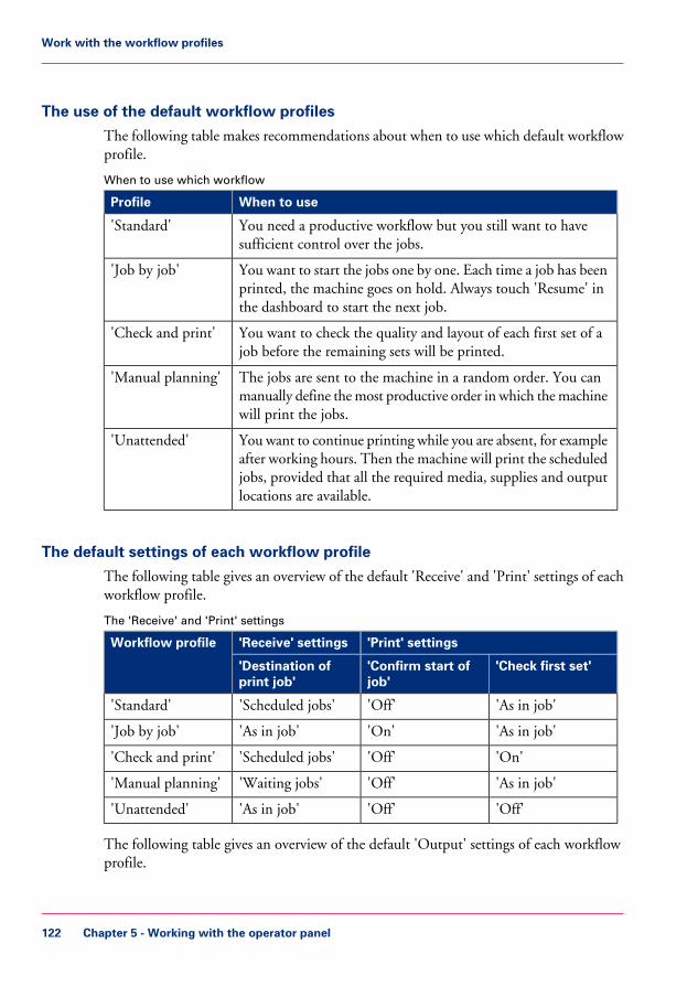
The use of the default workflow profiles
The following table makes recommendations about when to use which default workflowprofile.
When to use which workflow#
When to useProfile
You need a productive workflow but you still want to havesufficient control over the jobs.
'Standard'
You want to start the jobs one by one. Each time a job has beenprinted, the machine goes on hold. Always touch 'Resume' inthe dashboard to start the next job.
'Job by job'
You want to check the quality and layout of each first set of ajob before the remaining sets will be printed.
'Check and print'
The jobs are sent to the machine in a random order. You canmanually define the most productive order in which the machinewill print the jobs.
'Manual planning'
You want to continue printing while you are absent, for exampleafter working hours. Then the machine will print the scheduledjobs, provided that all the required media, supplies and outputlocations are available.
'Unattended'
The default settings of each workflow profile
The following table gives an overview of the default 'Receive' and 'Print' settings of eachworkflow profile.
The 'Receive' and 'Print' settings#
'Print' settings'Receive' settingsWorkflow profile
'Check first set''Confirm start ofjob'
'Destination ofprint job'
'As in job''Off''Scheduled jobs''Standard'
'As in job''On''As in job''Job by job'
'On''Off''Scheduled jobs''Check and print'
'As in job''Off''Waiting jobs''Manual planning'
'Off''Off''As in job''Unattended'
The following table gives an overview of the default 'Output' settings of each workflowprofile.
Chapter 5 - Working with the operator panel122
Work with the workflow profiles

The 'Output' settings#
'Output' settingsWorkflow profile
'Link output loca-tions'
'Offset stacking''Next output tray'
'On''Sets (as in job)''After each job''Standard'
'On''Sets (as in job)''After each job''Job by job'
'On''Sets (as in job)''After each job''Check and print'
'On''Sets (as in job)''After each job''Manual planning'
'Off''Banners''When tray is full''Unattended'
Note:The setting 'Link output locations' is only visible when 2 or more equally configuredstackers are available. For example, you cannot link the stackers when 1 stacker is con-figured for face-up media, while the other is configured for face-down media. Further-more, it is not possible to link a stacker to a finisher.
Values and effects of the settings
The following table describes the effects of the various values of the settings.
Values and effects of the settings#
EffectValuesSetting
The jobs are immediately sent to the list of'Scheduled jobs'. The machine will print the jobsin the ripped order. You can do the following torearrange the order in which the jobs will beprinted.• Move jobs to the list of 'Waiting jobs' or• Use 'To top' to move a job to the top of the
list of 'Scheduled jobs' (‘Give priority to a printjob’ on page 65).
'Scheduledjobs'
'Destination ofprint job'
You can manually define the order in which thejobs will be printed.
'Waiting jobs'
The submitted jobs go to the destination that isindicated in the job ticket.
'As in job'
Chapter 5 - Working with the operator panel 123
Work with the workflow profiles

EffectValuesSetting
The machine goes on hold after the first set of ajob is printed. You can check the quality and lay-out of the first set before the machine prints theremaining sets.
'On''Check firstset'
The machine will print the whole job withoutstopping after the first set.
'Off'
The machine will print the jobs as indicated in thejob ticket.
'As in job'
The machine always stops before the next sched-uled job. You must press the Release key to starteach job.
'On''Confirm startof job'
The machine prints the scheduled jobs one afterthe other. The machine does not stop before thenext scheduled job, unless there is a reason to stop.For example when a media is not available.
'Off'
The machine stops before a job when one or moresettings are overruled by the controller.
'On conflict'
Each job is sent to the next available output tray.In this context, the second stack of the stacker isalso defined as an output tray.
'After each job''Next outputtray'
All the jobs are stacked until an output tray is full.When an output tray is full, the next jobs are sentto the next output tray.
'When tray isfull'
Chapter 5 - Working with the operator panel124
Work with the workflow profiles

EffectValuesSetting
Each printed job that is delivered to an output lo-cation is stacked on top of the previous printedjob with an offset. This helps you to identify thevarious jobs.
'Jobs''Offset stack-ing'
The offset stacking is defined per N sets. By de-fault, this number is 1. If a number is specified,this specified number of printed sets of a job willbe delivered to an output location in one straightstack, the next number of printed sets are stackedwith an offset. When the number of requested setsin a job is lower than or equal to N, the sets arenot stacked with an offset. However, the wholejob is stacked with an offset with respect to theprevious job.
'Sets (always)'
Each printed set is delivered to the output locationas indicated in the job ticket. Therefore, the setscan be stacked in one straight line or with an offset.
'Sets (as injob)'
Each banner page of a job is delivered to the out-put location with an offset. This helps you toidentify the separate jobs. The jobs themselves arestacked in one straight line.
'Banners'
All the printed jobs or sets are stacked in onestraight line. There is no offset between the jobsor sets.
'Off'
Chapter 5 - Working with the operator panel 125
Work with the workflow profiles

Change the language
Introduction
This section describes how to change the language of the operator panel.
Change the language
1. On the operator panel, press the 'System' button.2. Press the 'Setup' button.
[69] Change the language
3. Press the 'Language' button in the 'User interface' section.
Chapter 5 - Working with the operator panel126
Change the language

An overview of the available languages appears.
[70] Overview of the available languages
4. Select your language, for example 'Norsk'.5. Press 'OK'.
The language is changed.
Chapter 5 - Working with the operator panel 127
Change the language

Change the warning time
Introduction
When operator interaction is required now or soon, the dashboard (see ‘The dashboard’on page 40) can display a warning message. The message informs you about a requiredupcoming action, for example load a required media type or empty an output location.You can define how long in advance the warning message is displayed. By factory default,the function 'Warning in advance' is enabled and set to 10 minutes. Then the dashboardstarts to display the warning 10 minutes before an action becomes inevitable. If you donot respond to the warning message, the printer will stop. Depending on the urgency ofthe warning message, the vertical bar in the dashboard is orange or red.This section describes how to change the warning time. This section also describes howto disable the function 'Warning in advance', in case you do not want to use the warningfunction.
Note:The operator attention light (see ‘The operator attention light’ on page 31) is linked tothe status of the machine. For example, when the dashboard displays an orange warning,the orange light of the operator attention light also lights up.
Set the warning time
1. On the operator panel, press the 'System' button.2. Press 'Setup'.3. Touch the 'Warning time' button in the 'User interface' section.4. Touch the - or + button to decrease or increase the warning time.
You can set a time from 1 - 60 minutes.5. Press 'OK'.
Disable the warning time
1. On the operator panel, press the 'System' button.2. Press 'Setup'.3. Touch the 'Warning time' button in the 'User interface' section.
A dialog box appears. When the 'Warning in advance' function is enabled, the 'Warningin advance' button displays a check mark and the status 'On'.
4. Touch the 'Warning in advance' button.The check mark disappears. The status 'On' changes into 'Off'.
5. Press 'OK'.
Chapter 5 - Working with the operator panel128
Change the warning time

Truncate the job name
Introduction
The operator panel displays all print and copy jobs with their job names in the 'Jobs'view. If a job name is too long, the system truncates the job name. To enable you toidentify your jobs in the lists more easily, you can define how the system truncates thejob names. This allows you to keep the identifying part of the job name. You can chooseto truncate the job name at the beginning or at the end of the name.
Illustration
[71]
How to truncate the job name
1. On the operator panel, press the 'System' button.2. Press 'Setup'.3. In the 'User interface' section, press the 'Job name truncation' button.4. Press the 'Job name truncation' button to change the truncation method.
You can choose to truncate at the 'Beginning' or the 'End' of the job name.5. Press the - or + button to change the number of characters before truncation.
Chapter 5 - Working with the operator panel 129
Truncate the job name

Change the advanced media settings
Introduction
The advanced media settings can help you solve problems when printing on certain specialmedia.
When all the advanced media settings have their default value, the button for 'Advancedmedia settings' displays the word 'Default'. After you changed one or more settings, thisbutton displays the word 'Custom'.This means that the 'Low temperature mode' is 'Off', 'Double-sheet detection' is 'Off',the 'Enhanced media mode' is 'On', 'Paper quality test' is 'On' or the 'Paper quality' isset to 'Low' or 'Lower'.
This section describes when it is recommended to change the advanced media settings.Furthermore, this section describes how to change the settings.
When to do
'Low temperature mode'
• Pre-printed: The system is able to handle pre-printed media without problems if theguidelines regarding pre-printed media and inks are taken into account. Contact yourlocal Océ representative to get a copy of these guidelines. In case media or inks areused that are not listed in the guidelines, the use of pre-printed media can lead toundesired print quality issues. To postpone print quality issues arising, a 'Low temper-ature mode' is available on the printer. It is advised to enable the 'Low temperaturemode' when there are problems with processing pre-printed media. The interval be-tween undesired print quality issues will then be increased significantly (for sometemperature sensitive inks, but no guarantee for all inks).It is advised to enable the 'Low temperature mode' when you process pre-printedmedia.It takes several minutes until 'Low temperature mode' is reached.The 'Low temperature mode' should not be enabled when you use media heavier than160 g/m2. This could lead to print problems.
• A secondary benefit (to pre-printed support) is to save energy. You can set the preheaterto a lower temperature.
'Double-sheet detection'Double-sheet detection warns you if 2 or more sheets have been separated from the mediastack in a paper tray at the same time. However, it is not always convenient to have thedouble-sheet detection enabled, for example when you use transparent media with acover sheet. Then you can set the 'Double-sheet detection' to 'Off'. By factory default,'Double-sheet detection' is 'On'.
Chapter 5 - Working with the operator panel130
Change the advanced media settings

'Enhanced media mode'Glossy media can cause a collating or stapling error in the finisher. You can set the 'En-hanced media mode' to 'On' to prevent the error. This will decrease the productivity ofthe machine. By factory default, the 'Enhanced media mode' is 'Off'. When you set the'Enhanced media mode' to 'On' and the machine status is 'Printing...', the dashboarddisplays a message that the enhanced media mode is enabled.The 'Enhanced media mode' is only available on machines that are equipped with anoptional finisher (see ‘The output locations’ on page 33).
'Paper quality'Good media is best run with the highest paper quality setting: 'Normal'.Lower grade media with respect to paper dust, such as some book papers for example,can leave more paper dust in the machine. This can lead to ghost images on prints directlyafter the black image cleaning procedure or to ghost images of previous pages on prints.When you use lower grade media, you can improve the print quality, with respect tothese undesired ghost images, by changing the value of the 'Paper quality' setting to 'Low'or even 'Lower'. However, this affects the productivity by almost 5 and 10% respectively.Please refer to the Troubleshooting chapter for more information (see ‘Troubleshooting’on page 247).
'Paper quality test'This test helps you to check if the correct 'Paper quality' setting is set. In the SettingsEditor, you can select the media for this test. It is advised to choose the media used forthe job. Or, in other cases, choose media which covers the width of the media used as aminimum. When you start the 'Paper quality test', the machine sends 5 empty sheets ofthe selected media to the system output. This is done after each of the next 5 black imagecleaning procedures. Keep in mind that this can last 2500, 1250 and 1000 sheets whenthe 'Paper quality' setting is set to 'Normal', 'Low' and 'Lower' respectively. Then thetest stops and the print job continues without interruption.Check the last set (fifth) of the empty sheets to see if the 'Paper quality' setting is cleaningthe print process properly.
Note:When the system goes into standby mode before the 'Paper quality test' has finished,the 'Paper quality test' starts again.
Before you begin
1. On the operator panel, press the 'System' button.2. Press 'Setup'.3. Touch the 'Advanced media settings' button in the 'Advanced' section.4. Enter the maintenance PIN when you change a setting.
Chapter 5 - Working with the operator panel 131
Change the advanced media settings

Note:The operator panel will only ask you to enter the maintenance PIN when a maintenancePIN is defined in the Settings Editor.
Enable the 'Low temperature mode'
1. Touch the 'Low temperature mode' button.The text on the button changes from 'Off' to 'On'.
Note:Each time you touch the button, the setting changes from 'On' to 'Off' and the otherway round.
2. Press 'OK'.When the 'Low temperature mode' is 'On', this is visible on the dashboard.
Disable the double-sheet detection
1. Touch the 'Double-sheet detection' button.The text on the button changes from 'On' to 'Off'.
Note:Each time you touch the button, the setting changes from 'On' to 'Off' and the otherway round.
2. Press 'OK'.
Enable the enhanced media mode
Caution:This setting is only available on machines that are equipped with an optional finisher.
Chapter 5 - Working with the operator panel132
Change the advanced media settings
1. Touch the 'Enhanced media mode' button.The text on the button changes from 'Off' to 'On'.
Note:Each time you touch the button, the setting changes from 'Off' to 'On' and the otherway round.
2. Press 'OK'.
Change the 'Paper quality'
1. Touch the 'Paper quality' button.A drop-down list appears.
2. Touch the desired value.3. Press 'OK'.
Start the 'Paper quality test'
1. Touch the 'Paper quality test' button to start the test.
Note:When the test is started, the progress of the test is displayed on the button and the texton the button changes from 'Start' to 'Stop'.
Note:When you touch the button again, the test is stopped.The text on the button changes from 'Stop' to 'Start'.
Note:The test stops automatically after the fifth set. You do not have to stop the 'Paper qualitytest' yourself.
Chapter 5 - Working with the operator panel 133
Change the advanced media settings

Make an intermediate check print
Introduction
The machine has a function that enables you to make a check print while a job is printed.This function is called the intermediate check print. When you use this function, themachine prints a copy of the sheet that is printed at the moment you press the 'Interme-diate check print' button. You can use this sheet to check whether the quality and consis-tency of the prints still meet your requirements.This section describes how to make an intermediate check print.
Note:You can also press the 'Intermediate check print' button when a job has not yet started.As soon as you press the Release key , a copy of the first sheet of the job will be printed.
Note:In the Settings Editor, you can also set the 'Interval of intermediate check print'.
Illustration
[73] Make an intermediate check print
Chapter 5 - Working with the operator panel134
Make an intermediate check print

Make an intermediate check print
1. On the operator panel, press the 'System' button.2. Press 'Setup'.3. Press the 'Intermediate check print' button in the 'Advanced' section.
The intermediate check print is sent to the system output (see ‘The output locations’ onpage 33).
Chapter 5 - Working with the operator panel 135
Make an intermediate check print

Change a number of settings in the Settings Editor via theoperator panel
Introduction
Note:The information contained in this section is primarily intended for key operators andsystem administrators.
The Settings Editor application on the PRISMAsync controller is a web based applicationthat allows key operators and system administrators to adapt the system to the situationin an organization and production environment. The Settings Editor allows key operatorsand system administrators to manage settings with regard to network configuration, systempreferences, job preferences and media, for example.For convenience reasons, a subset of frequently used settings is accessible through theoperator panel.
Settings available via the operator panel#
Short descriptionAvailable settingsGroup of settings
The 'About' section allows you to lookup the serial number and software versionof the printer.
• 'Serial number'(read-only)
• 'Version ofprinter soft-ware' (read-on-ly)
'About'
When you have a new license to activatea new feature on the printer, you can up-load the license through this section. Afteruploading the license, the feature becomesactive.Follow the instructions on the operatorpanel when you upload the license.
• 'Upload license''Software licenses'
Chapter 5 - Working with the operator panel136
Change a number of settings in the Settings Editor via the operator panel

Short descriptionAvailable settingsGroup of settings
When an error occurs, the help desk ofyour printer supplier can ask you to createand send a trace file and a datadump file.The datadump file is a .zip file that con-tains detailed technical information aboutyour system. Furthermore, the system canstore trace log files in .zip files. You cansave both .zip files to a USB drive.The configuration report contains infor-mation about the configuration of yourprinting system, for example informationabout the system configuration, controllerconfiguration and network settings. Youcan print the configuration report forbackup purposes, for example.Follow the instructions on the operatorpanel when you save a file or print a re-port.
• 'Save the datad-ump file'
• 'Save the tracefile'
• 'Print the config-uration report'
'Logging'
The 'Connectivity' section contains themain settings to integrate the printer intoa network. After you have adapted thenetwork settings, you can test the connec-tion from here.Follow the instructions on the operatorpanel when you adapt the network set-tings.
• 'MAC address'(read-only)
• 'Host name'• 'Link speed and
connectiontype'
• 'DHCP en-abled'
• 'TCP/IP ad-dress'
• 'Subnet mask'• 'Default gate-
way'• 'Primary DNS
suffix'• 'DNS suffix fol-
lows domain'• 'Test the
TCP/IP connec-tion'
'Connectivity'
Chapter 5 - Working with the operator panel 137
Change a number of settings in the Settings Editor via the operator panel

Short descriptionAvailable settingsGroup of settings
The 'System settings' section containssettings to change the date and time ofthe system, or the system of measurementused. When you change the system ofmeasurement, all corresponding valueson the system will be changed. For exam-ple, when you change 'Metric' into 'Impe-rial', all length values will be displayed ininches.
• 'Date and time'• 'System of mea-
surement'• 'Time zone'
'System settings'
How to change a number of settings in the Settings Editor via the operator panel
Note:The key operator PIN or the system administrator password is required to make changesin this section.
1. Touch 'System' -> 'Setup' -> 'Local key operator settings' (under 'Advanced').2. Touch the button of the group that contains the setting you want to change or view.3. Touch the required setting.4. Look up the required information or make the required changes.5. If you make a change, touch 'OK' to confirm.6. Press 'Close'.
Chapter 5 - Working with the operator panel138
Change a number of settings in the Settings Editor via the operator panel

The Media section
Introduction to the 'Media' section
Introduction
The 'System' view gives access to system settings, system information, media informationand maintenance tasks.This section gives an overview of the 'Media' section in the 'System' view.
Overview of the 'Media' section
[74] Overview of the 'Media' section
The items of the 'Media' sectionDescription of the 'Media' section#
More informationFunctionItemNum-ber
Display the currentcontent of the 'Mediacatalog'.
List of all the mediathat are available in the'Media catalog'.
1
Chapter 5 - Working with the operator panel 139
Introduction to the 'Media' section

More informationFunctionItemNum-ber
‘What are temporarymedia’ on page 142
Display the temporarymedia that are currentlyavailable on the system.
List of temporary media2
‘Add temporary media tothe 'Media catalog' ’ onpage 143
Add temporary mediato the media catalogue.
'To catalog' button3
‘Perform a media registra-tion for standard-sizemedia’ on page 145‘Perform a media registra-tion for large media’ onpage 152
Print test sheets andperform the registrationfor individual media.You can do a mediaregistration for stan-dard-size media andlarge media .
'Registration' button4
Chapter 5 - Working with the operator panel140
Introduction to the 'Media' section

Introduction to the media handling
Introduction
The machine supports a wide range of media, including tabs and inserts. The supportedmedia sizes range from 8 x 8 inch (minimum) to 12.5 x 19.2 inch (maximum). Thesupported media weights range from 33 - 202 lb bond for media that are recommendedby the manufacturer, and 40 - 135 lb bond for other media.
This section describes the following:• Media handling in general• The 'Media catalog'• Temporary media.
Note:You can place all the supported media in any paper tray.
General introduction to the media handling
All the print jobs require media that you can assign to the paper trays via the operatorpanel. The print jobs can require media that are included in the 'Media catalog'. However,the print jobs can also require media that are not included in the 'Media catalog'. Thesemedia become temporary media on the system.
What is the 'Media catalog'
The 'Media catalog' is a list of predefined media and media attributes which you can definein the Settings Editor application on the controller. The use of the 'Media catalog' isonly recommended, not compulsory.
When you use the 'Media catalog', the operator panel, the printer drivers and other ap-plications all display the same list of predefined media. The operator panel and theprinter driver automatically retrieve and show the latest version of the 'Media catalog'.
Note:Refer to the Online Help of the Settings Editor for information about the media attributesthat you can define. The Online Help also describes how to adapt the 'Media catalog'(add, edit or delete media).
Chapter 5 - Working with the operator panel 141
Introduction to the media handling

What are temporary media
You can also use many other media that are not included in the 'Media catalog'. Thesemedia become temporary media. You can look up the currently used temporary mediain the 'Media' section of the 'System' view. Furthermore, you can assign the temporarymedia to a paper tray.
The temporary media remain available on the system until:• No more waiting jobs need this media type• No more scheduled jobs need this media type• No more printed jobs need this media type• This media type is no longer available in the paper trays.
When you plan to use these media more often, you can add these temporary media tothe 'Media catalog' ‘Add temporary media to the 'Media catalog' ’ on page 143.
Chapter 5 - Working with the operator panel142
Introduction to the media handling

Add temporary media to the 'Media catalog'
Introduction
When a job is submitted that requires media that are not included in the 'Media catalog',these media become temporary media. The operator panel displays the temporary mediain the following places.• In the list of 'Required media' in the 'Schedule' view, when the job is scheduled for
printing.• In the list of 'Temporary media' in the 'Media' tab of the 'System' view.
When you plan to use a temporary media more often, you can add the media to the'Media catalog'.This section describes how to add temporary media to the 'Media catalog'.
Illustration
[75] Temporary media
Add temporary media to the 'Media catalog'
1. On the operator panel, press the 'System' button.
Chapter 5 - Working with the operator panel 143
Add temporary media to the 'Media catalog'

2. Press 'Media'.The names of the temporary media are displayed in the 'Temporary media' section.
3. Select the media you want to add to the 'Media catalog'.4. Press 'To catalog'.
The media is added to the 'Media catalog'.
Note:If required, you can edit the attributes of the media in the 'Media catalog' that is part ofthe Settings Editor.
Chapter 5 - Working with the operator panel144
Add temporary media to the 'Media catalog'

Perform a media registration for standard-size media
Introduction
The different properties of media can influence the alignment of images when the mediaare printed. To ensure a correct alignment, you can perform a media registration for eachindividual media in the 'Media catalog'. The following values will be measured.• The Z-position of side 1• The X-length of side 1• The Z-position of side 2• The X-position of side 1• The X-position of side 2.
For each media registration, a paper ruler and 3 test sheets will be printed. Dependingon the regional setting in the Settings Editor, the paper ruler is printed on A4 or Letter.You can use the first printed sheet to create the paper ruler. However, you can also use auniversal ruler of your own. The ruler must be long enough to carry out the measurements.You must carry out each measurement on all 3 test sheets. The system calculates the av-erage value of the measurements.This section describes how to perform a media registration for standard-size media (mediawith a length of less than 390 mm / 15.35").
Note:It is recommended to perform the media registration when the list of 'Scheduled jobs'is empty.
Before you begin
1. On the operator panel, press the 'System' button.2. Press 'Media'.3. Select a media from the 'Media catalog' for which you want to perform a media registra-
tion.4. Press 'Registration'.
When a maintenance PIN is defined in the Settings Editor, a numerical keyboard appears.5. Enter the maintenance PIN to start the wizard.
Note:The following procedures often refer to the start of the ruler. The start of the ruler isthe line where the shaft of the arrow starts.
Chapter 5 - Working with the operator panel 145
Perform a media registration for standard-size media

Print the test sheets and create the ruler
1. Read the introduction on the screen. Then press 'Next'.The printed test sheets go to the system output.
2. Take the first printed sheet.3. Fold the sheet along the line 'B-H' on side 1.
Test bitmap: REGISTRATION
Size: 210 x 297 mm
2006-10-09 / 14:08:36
Page 1
1Primary image
A
G
05-
0 05
+
3w
ek
st
ee
hS
-
B
H
D
C
I
F
[76] Fold the sheet to create a ruler
This is your ruler.
Test bitmap: REGISTRATION
Size: 210 x 297 mm
2006-10-09 / 14:08:36
Page 1
1Primary image
A
G
05-
0 05
+
3w
ek
st
ee
hS
-
B
H
D
Test bitmap: REGISTRATION
Size: 210 x 297 mm
2006-10-09 / 14:08:36
Page 1
1Primary image
A
G
05-
0 05
+
3w
ek
st
ee
hS
-
B
H
D
1000
1050
1100
1150
1200
1250
1300
1350
1400
1450
1500
1550
1600
1650
1700
1750
1800
1850
1900
1950
2000
2050
2100
2150
2200
2250
2300
2350
2400
2450
2500
2550
2600
2650
2700
2750
2800
-50
0
+50
Primary X image position
Primary Z image position
Primary diamond shape
X length
L
[77] The ruler
Chapter 5 - Working with the operator panel146
Perform a media registration for standard-size media

Adjust the Z-position of side 1
1. Take the first test sheet.2. Align the start of the ruler with point 'B' of the test sheet.
Test bitmap: REGISTRATION
Size: 210 x 297 mm
2006-10-09 / 14:08:36
Page 1
1Primary image
AC
GI
05-
005
+
3w
ek
st
ee
hS
-
B
H
DF
1000
1050
1100
1150
1200
1250
1300
1350
1400
1450
1500
1550
1600
1650
1700
1750
1800
1850
1900
1950
2000
2050
2100
2150
2200
2250
2300
2350
2400
2450
2500
2550
2600
2650
-50
0
+50
Primary X image position
Primary Z image position
Primary diamond shape
X length
L
B
-50
0
+50
[78] Align the ruler with 'B'
3. Read the value at the edge of the test sheet.4. Enter the value.5. Take the second test sheet.6. Repeat the steps 2 - 4.7. Take the third test sheet.8. Repeat the steps 2 - 4.
Adjust the X-length of side 1
1. Take the first test sheet.2. Put the ruler along the line 'D-F' of the test sheet.
Chapter 5 - Working with the operator panel 147
Perform a media registration for standard-size media

3. Align the start of the ruler with point 'D' of the test sheet.
Test b
itmap
: RE
GIS
TR
AT
ION
Size: 2
10 x
297 m
m
2006-1
0-0
9 / 1
4:0
8:3
6
Pag
e 1
1P
rimary
imag
e
AC
GI
05-
0
05+
3 weksteehS-
BH
DF
1000
1050
1100
1150
1200
1250
1300
1350
1400
1450
1500
1550
1600
1650
1700
1750
1800
1850
1900
1950
2000
2050
2100
2150
2200
2250
2300
2350
2400
2450
2500
2550
2600
2650
2700
2750
2800
-50
0
+50
Primary X image position
Primary Z image position
Primary diamond shape
X length
L
F
1500
1550
1600
1650
1700
1750
1800
1850
1900
1950
2000
2050
2100
1D-50
0
+50
[79] Align the ruler with 'D''
4. Read the value at point 'F'.5. Enter the value.6. Take the second test sheet.7. Repeat the steps 2 - 5.8. Take the third test sheet.9. Repeat the steps 2 - 5.
Adjust the Z-position of side 2
1. Take the first test sheet.
Chapter 5 - Working with the operator panel148
Perform a media registration for standard-size media

2. Align the start of the ruler with point 'K' of the test sheet.
Test bitmap: REGISTRATION
Size: 210 x 297 mm
2006-10-09 / 14:08:36
Page 2
2Secondary image
05-
0 05
+
2 e
pa
hS
dn
om
aiD
yra
dn
oc
eS
2
05-
005
+
1 e
pa
hS
dn
om
aiD
yra
dn
oc
eS
10
5-
0 05
+
noi
t is
op
eg
ami
X
y ra
dn
oc
eS
5
-50
0
+50
Secondary Z image position
4-50
0
+50
Primary X image position
Primary Z image position
1000
1050
1100
1150
1200
1250
1300
1350
1400
1450
1500
1550
1600
1650
1700
1750
1800
1850
1900
1950
2000
2050
2100
2150
2200
2250
2300
2350
2400
2450
2500
2550
2600
2650
2700
2750
2800
Primary diamond shape
X length
K
NL
P
1000
1050
1100
1150
1200
1250
1300
1350
1400
1450
1500
1550
1600
1650
1700
1750
1800
1850
1900
1950
2000
2050
2100
2150
2200
2250
2300
2350
2400
2450
2500
2550
2600
2650
-50
0
+50
Primary X image position
Primary Z image position
Primary diamond shape
X length
L
Secondary Z image positio
-50
0
+50
K
-50
0
+50
[80] Align the ruler with 'K'
3. Read the value at the edge of the test sheet.4. Enter the value.5. Take the second test sheet.6. Repeat the steps 2 - 4.7. Take the third test sheet.8. Repeat the steps 2 - 4.
Note:After step 8, the machine prints another 3 test sheets to measure the X-position of side1 and side 2.
Adjust the X-position of side 1
1. Take the first test sheet.2. Put the ruler along the line 'D-F' of the test sheet.
Chapter 5 - Working with the operator panel 149
Perform a media registration for standard-size media

3. Align the start of the ruler with the left edge of the test sheet.
Test b
itmap
: RE
GIS
TR
AT
ION
Size: 2
10 x
297 m
m
2006-1
0-0
9 / 1
4:0
8:3
6
Pag
e 1
1P
rimary
imag
e
AC
GI
05-
0
05+
3 weksteehS-
BH
DF
1000
1050
1100
1150
1200
1250
1300
1350
1400
1450
1500
1550
1600
1650
1700
1750
1800
1850
1900
1950
2000
2050
2100
2150
2200
2250
2300
2350
2400
2450
2500
2550
2600
2650
2700
2750
2800
-50
0
+50
Primary X image position
Primary Z image position
Primary diamond shape
X length
L
1D
-50
0
+50
[81] Align the ruler with the edge of the sheet
4. Read the value at point 'D'.5. Enter the value.6. Take the second test sheet.7. Repeat the steps 2 - 5.8. Take the third test sheet.9. Repeat the steps 2 - 5.
Adjust the X-position of side 2
1. Take the first test sheet.2. Align the start of the ruler with point 'N' of the test sheet.
Test bitmap: REGISTRATION
Size: 210 x 297 mm
2006-10-09 / 14:08:36
Page 2
2Secondary image
05-
0 05
+
2 e
pa
hS
dn
om
aiD
yra
dn
oc
eS
2
05-
005
+
1 e
pa
hS
dn
om
aiD
yra
dn
oc
eS
10
5-
0 05
+
noi
t is
op
eg
ami
X
y ra
dn
oc
eS
5
-50
0
+50
Secondary Z image position
4-50
0
+50
Primary X image position
Primary Z image position
1000
1050
1100
1150
1200
1250
1300
1350
1400
1450
1500
1550
1600
1650
1700
1750
1800
1850
1900
1950
2000
2050
2100
2150
2200
2250
2300
2350
2400
2450
2500
2550
2600
2650
2700
2750
2800
Primary diamond shape
X length
K
NL
P
-50
0
+50
Primary X image position
Primary Z image position
05-
0 05
+
t is
op
eg
ami
X
y ra
dn
oc
eS
5
N
-50
0
+50
[82] Align the ruler with 'N'
3. Read the value at the edge of the test sheet.4. Enter the value.
Chapter 5 - Working with the operator panel150
Perform a media registration for standard-size media

5. Take the second test sheet.6. Repeat the steps 2 - 4.7. Take the third test sheet.8. Repeat the steps 2 - 4.
Result
A pop-up message appears. The message asks you whether you want to print an extra testsheet to verify the result of the registration. You can do one of the following.• Press 'Yes' if you want to print an extra test sheet to verify the result.
Wait for the sheet and check the result. Another pop-up message appears. Press 'Yes'if the registration is correct. Press 'No' if the registration is not correct. Then the reg-istration procedure will start again.
• Press 'No' if you do not want to print an extra test sheet. The registration procedurewill be finished.
Chapter 5 - Working with the operator panel 151
Perform a media registration for standard-size media

Perform a media registration for large media
Introduction
The different properties of media can influence the alignment of images when the mediaare printed. To ensure a correct alignment, you can perform a media registration for eachindividual media in the 'Media catalog'. The following values will be measured.• The Z-position of side 1• The X-length of side 1• The Z-position of side 2• The X-position of side 1• The X-position of side 2.
For each media registration, a paper ruler and 3 test sheets will be printed. Dependingon the regional setting in the Settings Editor, the paper ruler is printed on A4 or Letter.You can use the first printed sheet to create the paper ruler. However, you can also use auniversal ruler of your own. The ruler must be long enough to carry out the measurements.You must carry out each measurement on all 3 test sheets. The system calculates the av-erage value of the measurements.This section describes how to perform a media registration for large media (media witha length of 390 mm / 15.35" or more).
Note:It is recommended to perform the media registration when the list of 'Scheduled jobs'is empty.
Before you begin
1. On the operator panel, press the 'System' button.2. Press 'Media'.3. Select a media from the 'Media catalog' for which you want to perform a media registra-
tion.4. Press 'Registration'.
When a maintenance PIN is defined in the Settings Editor, a numerical keyboard appears.5. Enter the maintenance PIN to start the wizard.
Note:The following procedures often refer to the start of the ruler. The start of the ruler isthe line where the shaft of the arrow starts.
Chapter 5 - Working with the operator panel152
Perform a media registration for large media

Print the test sheets and create the ruler
1. Read the introduction on the screen. Then press 'Next'.The printed test sheets go to the system output.
2. Take the first printed sheet.3. Fold the sheet along the line 'B-H' on side 1.
Test bitmap: REGISTRATION
Size: 210 x 297 mm
2006-10-09 / 14:08:36
Page 1
1Primary image
A
G
05-
0 05
+
3w
ek
st
ee
hS
-
B
H
D
C
I
F
[83] Fold the sheet to create a ruler
This is your ruler.
Test bitmap: REGISTRATION
Size: 210 x 297 mm
2006-10-09 / 14:08:36
Page 1
1Primary image
A
G
05-
0 05
+
3w
ek
st
ee
hS
-
B
H
D
Test bitmap: REGISTRATION
Size: 210 x 297 mm
2006-10-09 / 14:08:36
Page 1
1Primary image
A
G
05-
0 05
+
3w
ek
st
ee
hS
-
B
H
D
1000
1050
1100
1150
1200
1250
1300
1350
1400
1450
1500
1550
1600
1650
1700
1750
1800
1850
1900
1950
2000
2050
2100
2150
2200
2250
2300
2350
2400
2450
2500
2550
2600
2650
2700
2750
2800
-50
0
+50
Primary X image position
Primary Z image position
Primary diamond shape
X length
L
[84] The ruler
Chapter 5 - Working with the operator panel 153
Perform a media registration for large media

Adjust the Z-position of side 1
1. Take the first test sheet.2. Align the start of the ruler with point 'B' of the test sheet.
Test bitmap: REGISTRATION
Size: 420 x 297 mm
2006-10-09 / 14:08:22
Page 1
1Primary image
-50
0
+50
3 - Sheet skew
B
H
ED F
1000
-50
0
+50
Primary X image position
Primary Z image position
B
-50
0
+50
[85] Align the ruler with 'B'
3. Read the value at the edge of the test sheet.4. Enter the value.5. Take the second test sheet.6. Repeat the steps 2 - 4.7. Take the third test sheet.8. Repeat the steps 2 - 4.
Adjust the X-length of side 1
1. Take the first test sheet.
Chapter 5 - Working with the operator panel154
Perform a media registration for large media

2. Align the start of the ruler with point 'D' and read the value at point 'E'.
Test b
itmap
: RE
GIS
TR
AT
ION
Size: 4
20 x
297 m
m
2006-1
0-0
9 / 1
4:0
8:2
2
Pag
e 1
1P
rimary
imag
e
-50 0
+50 3
- Sheet s
kew
BH ED
F
1000
1050
1100
1150
1200
1250
1300
1350
1400
1450
1500
1550
1600
1650
1700
1750
1800
1850
1900
1950
2000
2050
2100
2150
2200
2250
2300
2350
2400
2450
2500
2550
2600
2650
2700
2750
2800
-50
0
+50
Primary X image position
Primary Z image position
Primary diamond shape
X length
L
1D-50
0
+50
E
1500
1550
1600
1650
1700
1750
1800
1850
1900
1950
2000
2050
2100
[86] Align the ruler with 'D' and read the value at 'E'
3. Open the 'Calculator assistant', enter the 'DE' value and press 'OK'.4. Align the start of the ruler with point 'E' and read the value at point 'F'.
Test b
itmap
: RE
GIS
TR
AT
ION
Size: 4
20 x
29
7 m
m
20
06-1
0-0
9 / 1
4:0
8:2
2
Pag
e 1
1P
rimary
imag
e
-50 0
+50 3
- Sh
ee
t ske
w
BH ED
F
1000
1050
1100
1150
1200
1250
1300
1350
1400
1450
1500
1550
1600
1650
1700
1750
1800
1850
1900
1950
2000
2050
2100
2150
2200
2250
2300
2350
2400
2450
2500
2550
2600
2650
2700
2750
2800
-50
0
+50
Primary X image position
Primary Z image position
Primary diamond shape
X length
L
E-50
0
+50F
1700
1750
1800
1850
1900
1950
2000
2050
2100
2150
2200
2250
2300
[87] Align the ruler with 'E' and read the value at 'F'
5. Open the 'Calculator assistant', enter the 'EF' value and press 'OK'.6. Take the second test sheet.7. Repeat the steps 2 - 5.8. Take the third test sheet.9. Repeat the steps 2 - 5.
Chapter 5 - Working with the operator panel 155
Perform a media registration for large media

Adjust the Z-position of side 2
1. Take the first test sheet.2. Align the start of the ruler with point 'K' of the test sheet.
Test bitmap: REGISTRATION
Size: 420 x 297 mm
2006-10-09 / 14:08:22
Page 2
2Secondary image
K
P
M LN
1000
1050
1100
1150
1200
1250
-50
0
+50
Primary X image position
Primary Z image position
Primary diamond shape
X length
L
K
-50
0
+50
[88] Align the ruler with 'K'
3. Read the value at the edge of the test sheet.4. Enter the value.5. Take the second test sheet.6. Repeat the steps 2 - 4.7. Take the third test sheet.8. Repeat the steps 2 - 4.
Note:After step 8, the machine prints another 3 test sheets to measure the X-position of side1 and side 2.
Adjust the X-position of side 1
1. Take the first test sheet.2. Put the ruler along the line 'D-F' of the test sheet.
Chapter 5 - Working with the operator panel156
Perform a media registration for large media

3. Align the start of the ruler with the left edge of the test sheet.
Test b
itmap
: RE
GIS
TR
AT
ION
Size: 4
20
x 2
97
mm
2006
-10-0
9 / 1
4:0
8:2
2
Pag
e 1
1P
rimary
imag
e
-50 0
+50 3
- Sh
ee
t ske
w
BH ED
F
1000
1050
1100
1150
1200
1250
1300
1350
1400
1450
1500
1550
1600
1650
1700
1750
1800
1850
1900
1950
2000
2050
2100
2150
2200
2250
2300
2350
2400
2450
2500
2550
2600
2650
2700
2750
2800
-50
0
+50
Primary X image position
Primary Z image position
Primary diamond shape
X length
L
1D
-50
0
+50
[89] Align the ruler with the edge of the sheet
4. Read the value at point 'D'.5. Enter the value.6. Take the second test sheet.7. Repeat the steps 2 - 5.8. Take the third test sheet.9. Repeat the steps 2 - 5.
Adjust the X-position of side 2
1. Take the first test sheet.
Chapter 5 - Working with the operator panel 157
Perform a media registration for large media
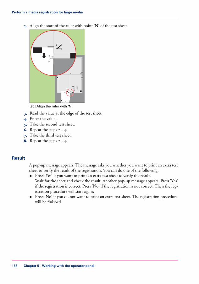
2. Align the start of the ruler with point 'N' of the test sheet.
Test b
itmap
: RE
GIS
TR
AT
ION
Size: 4
20 x
297 m
m
2006-1
0-0
9 / 1
4:0
8:2
2
Pag
e 2
2S
econdary
imag
e
KP ML
N
1000
1050
1100
1150
1200
1250
-50
0
+50
Primary X image position
Primary Z image position
Primary diamond shape
X length
L
N
-50
0
+50
[90] Align the ruler with 'N'
3. Read the value at the edge of the test sheet.4. Enter the value.5. Take the second test sheet.6. Repeat the steps 2 - 4.7. Take the third test sheet.8. Repeat the steps 2 - 4.
Result
A pop-up message appears. The message asks you whether you want to print an extra testsheet to verify the result of the registration. You can do one of the following.• Press 'Yes' if you want to print an extra test sheet to verify the result.
Wait for the sheet and check the result. Another pop-up message appears. Press 'Yes'if the registration is correct. Press 'No' if the registration is not correct. Then the reg-istration procedure will start again.
• Press 'No' if you do not want to print an extra test sheet. The registration procedurewill be finished.
Chapter 5 - Working with the operator panel158
Perform a media registration for large media

The Transaction section (optional)
Introduction to the 'Transaction' section
Introduction
When the printer contains the optional IPDS or PCL license for transaction printing,the printer can be used both for document printing and transaction printing. Then youcan print typical transactional documents like invoices, salary slips or other variable datastreams. If you want to use the printer for transaction printing, you must first switch theprinter from the document printing mode to the transaction printing mode. This is onlypossible when the list of 'Scheduled jobs' is empty. When the list of 'Scheduled jobs' isempty, you can activate the transaction printing function on the operator panel and sendjobs from a server or mainframe. The 'Transaction' section on the operator panel containsthe settings that you need to prepare the printer for transaction printing.
The following information is described below.• An overview of the items in the 'Transaction' section on the operator panel• The sequence of steps for transaction printing on this printer.
The activation of the transaction printing function on the printer is described in a separatesection (see ‘Activate the transaction printing function’ on page 168).
Note:The operator panel displays the 'Transaction' section only when the printer has a licensefor transaction printing.
Chapter 5 - Working with the operator panel 159
Introduction to the 'Transaction' section

Overview of the 'Transaction' section
1
4
32
[91] Overview of the 'Transaction' section
The items of the 'Transaction' sectionDescription of the 'Transaction' section#
FunctionItemNum-ber
The dashboard displays the following informationfor transaction printing.• The connection status• The IP address of the server sending the jobs• The name of the transaction stream• The progress of the transaction stream
Dashboard1
Chapter 5 - Working with the operator panel160
Introduction to the 'Transaction' section

FunctionItemNum-ber
The 'Connection' section gives access to the follow-ing functions.• Turn the transaction printing function on or
off• Put the printer on-line. This is required to
connect the printer to the server• Select the setup for the transaction stream
'Connection'2
Display the active printer description language(read-only)
'Print protocol'3
Display and change the image shift'Image shift'4
Sequence of steps for transaction printing
The following table describes the sequence of steps for transaction printing in general.
#
Actions on the server sideActions at the printer side
1. Switch the printer into the transactionprinting mode
2. Select the required job setup via theoperator panel. You must define theproperties of the job setup in the SettingsEditor application on the Controller
3. Load the required media into the papertrays
4. Place the printer on-line
5. Connect to the printer
6. Start the transaction stream
7. Print the transaction stream
Note:You must perform all the regularactivities, for example loading themedia, emptying the output loca-tions, adding supplies and solvingerrors
Chapter 5 - Working with the operator panel 161
Introduction to the 'Transaction' section

Actions on the server sideActions at the printer side
8. Place the printer off-line when thetransaction stream is ready
9. Switch the printer back to documentprinting mode
Chapter 5 - Working with the operator panel162
Introduction to the 'Transaction' section

Error handling and output recovery
Introduction
TheOcé VarioPrint® 6000 Ultra Line is equipped with very efficient and reliable errorrecovery. Some printing environments, however, require that multiple copies be avoided.For example, in transactions involving the printing of valuable documents such as cheques.In such an environment, you can enable the output recovery functionality.
Output recovery means that automatic error recovery is suppressed. Errors are recoveredby the server. All pending pages in the printer will be deleted. An error results in a stackeject. This means that it is the responsibility of the operator to restart the job manuallyon the correct page, in case of an error. By default, output recovery is disabled. In theSettings Editor, you can enable output recovery in the IPDS transaction printing setups.PCL transaction printing does not support output recovery.
This section describes the difference between the default error handling and the errorhandling with output recovery enabled.
Note:You can enable output recovery in IPDS transaction printing setups only.
Note:When you enable output recovery, the intermediate check print and the sample sheetinterval are automatically disabled.
Error handling with output recovery in IPDS
The table shows what happens when an error occurs during a transaction print job withoutput recovery. Pages that are copied to the memory of the controller are deleted fromthe system. The operator must send these missing pages to the printer as a (new) printjob transaction.
Chapter 5 - Working with the operator panel 163
Error handling and output recovery

#
End up in the out-put location aftererror recovery
Output recoverywith IPDS
Job progressstates
Job
Sheets are in out-put location
Are stacked at oneof the output loca-tions.
Sheets printed suc-cessfully
These sheets arenot delivered to theoutput location.
Are deleted com-pletely.
Sheets copied tocontroller memory(including errorpages).
These sheets arenot delivered to theoutput location.
The operator paneldisplays instruc-tions on how tosolve the paperjam. The operatorhas to remove thesethe jammed sheetsmanually.Sheets jammed in
the machine.
Remain in hostmemory.
Sheets in hostmemory.
Chapter 5 - Working with the operator panel164
Error handling and output recovery

End up in the out-put location aftererror recovery
Output recoverywith IPDS
Job progressstates
Job
Once the error isresolved, the print-er restarts by print-ing the first page inthe host memory.
Chapter 5 - Working with the operator panel 165
Error handling and output recovery

Error handling with output recovery disabled in IPDS#
End up in the out-put location aftererror recovery
Output recoverydisabled (e.g. PCLand PS)
Job progressstates
Job
Sheets are in out-put location
Are stacked at oneof the output loca-tions.
Sheets printed suc-cessfully.
Once the error isresolved, the print-er restarts by print-ing the first page inthe controllermemory.
Remain in con-troller memory.
Sheets copied tocontroller memory(including errorpages).
These sheets stay inthe memory of thecontroller. Oncethe printer resumesprinting, thesepages will be print-ed again.
The operator paneldisplays instruc-tions on how tosolve the paperjam. The operatorhas to remove thesethe jammed sheetsmanually.Sheets jammed in
the machine.
Chapter 5 - Working with the operator panel166
Error handling and output recovery

End up in the out-put location aftererror recovery
Output recoverydisabled (e.g. PCLand PS)
Job progressstates
Job
These sheets stay inthe host memory.When the printerstarts printing,these pages will becopied and sent tothe controller.
Remain in hostmemory.
Sheets in hostmemory.
Available counters
The Océ VarioPrint® 6000 Ultra Line supports the standard IPDS counters.
Chapter 5 - Working with the operator panel 167
Error handling and output recovery

Activate the transaction printing function
Introduction
To use the transaction printing function, you must first activate this function (see ‘Intro-duction to the 'Transaction' section ’ on page 159). This section describes the following:• How to activate transaction printing mode• How to switch back to document printing mode.
Before you begin
Make sure that the list of 'Scheduled jobs' is empty.
Illustration
[110] The transaction printing pane
Switch to transaction printing mode
1. On the operator panel, press the 'System' button.2. Press the 'Transaction' button.
Chapter 5 - Working with the operator panel168
Activate the transaction printing function

3. Press the 'Transaction printing mode' button.The text on the button changes from 'Off' to 'On'.
4. Press the 'Active transaction setup' button and select the required setup.The attributes of the transaction setup are defined in the Settings Editor application onthe Controller.
5. Load the required media into the paper trays.6. Press the 'Transaction on-line' button.
The text on the button changes from 'Off' to 'On'.7. On the server, connect to the printer and start the job.
Note:When a job is ready, you can start another transactional job or switch back to the docu-ment printing mode.
Switch to the document printing mode
1. On the operator panel, press the 'System' button.2. Press the 'Transaction' button.3. Press the 'Transaction on-line' button.
The text on the button changes from 'On' to 'Off'.Note that you can only switch the 'Transaction on-line' function to off-line when• the transaction stream is ready• the printer contains no more print data• the printer has stopped normally (not due to an error).
When you switch the 'Transaction on-line' function to off-line, the connection to thehost is disconnected.
4. Press the 'Transaction printing mode' button.The text on the button changes from 'On' to 'Off'.
Chapter 5 - Working with the operator panel 169
Activate the transaction printing function

Shift the image in the transaction printing mode
Introduction
When you use pre-printed media with marked locations for specific text, for example, amisalignment of the text can occur. For example, an address is not exactly placed in thecenter of an address field, or an account number is not exactly placed in the appropriatebox. To correct these misalignments, you can shift the image. You can shift the imageson the front side and back side horizontally and vertically.This section describes how to shift the image.
Illustration
[111] Shift the image
Shift the image
Note:Only use the image shift function if you want to shift the image of the whole job. Theimage shift applies to all the media in all the paper trays.
Chapter 5 - Working with the operator panel170
Shift the image in the transaction printing mode

1. On the operator panel, press the 'System' button.2. Press 'Transaction'.3. Press the - or + buttons to shift the image on the front side or back side of the sheet.
Chapter 5 - Working with the operator panel 171
Shift the image in the transaction printing mode

Handle the media messages
Introduction
The media catalog• contains a list of predefined media and their attributes• is an essential part of the system behavior of the Océ VarioPrint® 6000 Ultra Line• helps you to print your jobs more easily while using the correct media
For transaction printing, the content of the paper trays (in terms of media from the mediacatalogue) is translated into a format that the SRA controller understands. However, thecontroller receives only a limited amount of information (name or size of the media).This can lead to miscommunication where the controller misses a media requirement.The controller will then ask for the required media via a message on the operator panel.This 'Media message' indicates the name or size of the missing media.
Your response to the'Media message' depends on the mode in which the printer works,either:• The tray-to-tray mode, or• The tray-to-media mode.
This section describes how to respond to the 'Media message' for both modes.
Note:A 'Media message' will only occur when the printer description language is PCL.
Chapter 5 - Working with the operator panel172
Handle the media messages

Illustration
[112] Example of a 'Media message'
How to handle the 'Media message' in the tray-to-tray mode
1. A message on the operator panel indicates that a media is missing. Select one of the fol-lowing actions as a response to the message.• Press 'Assign media'.
Continue with step 2 when you select this option.• Press 'Continue'.
The controller will use the PCL default media and continue the print job.Note that this might be an incorrect media.
• Press 'Cancel stream'.The print job is stopped. You can now solve the problem. You will most likely be ableto solve the problem on the server.
Note:Steps 2 and 3 apply only when you chose to assign a media.
Chapter 5 - Working with the operator panel 173
Handle the media messages

2. From the list of media, select the media that will be used as the media the controller isasking for and press 'OK'.Note that this might be an incorrect media.The media will now be displayed with the name that is defined in the media catalog.
3. Select the paper tray where you want to load the required media and press 'OK'.4. Load the media.5. Close the paper tray.6. Press 'OK'.
Now you can assign other media or continue the print job.
How to handle the 'Media message' in the tray-to-media mode
1. A message on the operator panel indicates that a media is missing. Select one of the fol-lowing actions as a response to the message.• Press 'Assign media'.
Continue with step 2 when you select this option.• Press 'Continue'.
The controller will use the PCL default media and continue the print job.Note that this might be an incorrect media.
• Press 'Cancel stream'.The print job is stopped. You can now solve the problem. You will most likely be ableto solve the problem on the server.
Note:The following steps apply only when you chose to assign a media.
2. From the list of media, select the media that will be used as the media the controller isasking for and press 'OK'.Note that this might be an incorrect media.
3. Select one of the 16 memory locations of the logical-tray table to be used for the requiredmedia.Note that the media that was previously allocated to that memory position in the setupwill be overwritten. Then that media will no longer be available to the transaction stream.Now you can assign other media or continue the print job.
Chapter 5 - Working with the operator panel174
Handle the media messages

Create a transaction setup
Introduction
When you want to use transaction printing, you have to create the necessary transactionsetups. You can create these setups in the Settings Editor.
Note:If the Settings Editor does not display the correct language, you can change the preferredlanguage in the internet options of your internet browser. The desired language mustbe first in the list of languages.
How to create a new transaction setup
1. Go to 'Transaction Printing' - 'Setups' .2. Click the 'Add' button.
A pop-up window appears.3. Type in the name and the description of the transaction setup.4. Click 'Ok'.5. Place a checkmark in front of the transaction setup to select the setup.6. Change the settings (see ‘How to change the IPDS parameters’ on page 175 or ‘How to
change the PCL parameters’ on page 176).You can change the settings:• by group (click the pencil at the right-hand side of the group settings). This is the
preferred method.• by item (click the pencil behind the individual settings).
Note:The status of the setup is changed to modified. You have to load the setup to make thesemodifications available on the printer.Before you can load a transaction setup, you have to switch the transaction printing modeoff-line.
7. Go to 'Transaction Printing' - 'Settings', and click 'Toggle the transaction printing mode'to switch the printer off-line.
8. Go to 'Transaction Printing' - 'Setups', and click 'Load'.The setup is now available on your operator panel.
How to change the IPDS parameters
1. Go to 'Transaction Printing' - 'IPDS setup'.
Chapter 5 - Working with the operator panel 175
Create a transaction setup

2. Make sure that the Tray selection mechanism is set to Tray to Media.This is the preferred setting. This printer is a media-based machine. The Tray-to-mediamethod supports this behavior.
3. Change the settings under the 'IPDS setup' tab.You can change the settings:• by group (click the pencil at the right-hand side of the group settings). This is the
preferred method.• by item (click the pencil behind the individual settings).
4. For 'IPDS Tray to media for media 1' assign the 'Media catalog item' from the list. Thelist displays all the media in the media catalog. The system copies the media attributesfrom the selected media to the transaction setup.When you assign A3/Ledger-like media or want to use short-edge feed for other media,change the feed direction to 'Short-edge feed (SEF)'.
Note:The settings editor displays only the media for which the media name is consistent withthe IPDS media name definitions. Valid characters for an IPDS media name are: A-Z,a-z, 0-9, blank.
5. Repeat step 4 for all the logical trays in your setup.
How to change the PCL parameters
1. Go to 'Transaction Printing' - 'PCL setup'.2. Make sure that the Tray selection mechanism is set to Tray to Media.
This is the preferred setting. This printer is a media-based machine. The Tray-to-mediamethod supports this behavior.
3. Change the settings under the 'PCL setup' tab.You can change the settings:• by group (click the pencil at the right-hand side of the group settings). This is the
preferred method.• by item (click the pencil behind the individual settings).
4. For 'PCL Tray to media for media 1' assign the 'Media catalog item' from the list. Thelist displays all the media in the media catalog.When you assign A3/Ledger-like media or want to use short-edge feed for other media,change the feed direction to 'Short-edge feed (SEF)'.
5. Repeat Step 4 for all the logical trays in your setup.
Chapter 5 - Working with the operator panel176
Create a transaction setup

Note:When you have more than one printer, you can exchange transaction setups. Go to'Transaction Printing' - 'Setups' and use the 'Import' and 'Export' functions.
How to modify a transaction setup
1. Go to 'Transaction Printing' - 'Setups'.2. Put a checkmark in front of the transaction setup to select the setup you want to modify.3. Click the 'Edit' button, if you want to change the name of the setup.4. Change the settings under the 'IPDS setup' tab (see ‘How to change the IPDS parameters’
on page 175).You can change the settings:• by group (click the pencil at the right-hand side of the group settings). This is the
preferred method.• by item (click the pencil behind the individual settings).
5. Change the settings under the 'PCL setup' tab (see ‘How to change the PCL parameters’on page 176).
6. Change the values under the 'Settings' tab.
Note:The status of the setup is changed to modified. You have to load the setup to make thesemodification available on the printer.Before you can load a transaction setup, you have to switch the transaction printing modeoff-line.
7. Go to 'Transaction Printing' - 'Settings', and click 'Toggle the transaction printing mode'to switch the printer off-line.
8. Go to back'Transaction Printing' - 'Setups'.9. Click 'Load'.
The setup is now available on your operator panel.
Chapter 5 - Working with the operator panel 177
Create a transaction setup

Chapter 5 - Working with the operator panel178
Create a transaction setup

Chapter 6Optional finishers andother devices

iXDP (integrated eXchangeableDie Punch) - VarioPrint® 6160 onlyIntroduction
Introduction
Illustration
[113] The puncher (iXDP)
'The puncher enables you to finish documents for various types of binding. Simply replacethe die set inside the puncher to get another type of binding.
Information about the die sets.
Chapter 6 - Optional finishers and other devices180
Introduction

• The die sets are self-latching. You do not need tools or levers to replace a die set.• Each die set has an identification label that shows the hole pattern and name.• You can store 3 additional die sets in a storage area inside the puncher (see ‘Main parts’
on page 182).
Chapter 6 - Optional finishers and other devices 181
Introduction

Operating information
Main parts
Illustration
Chapter 6 - Optional finishers and other devices182
Main parts

K3
K7
K3
K7
1
0
K3
K7
6
1
2
3
4
5
[114] Main parts of the puncher
Chapter 6 - Optional finishers and other devices 183
Main parts

Description of the main partsDescription of the main parts#
DescriptionPart
The bypass is a short straight-through paper path fordocuments that must not be punched.
Bypass1
Documents that must be punched follow the U-shapedpunch path. The puncher can handle media up to 216g/m² (80 lb. cover).
Punch path2
The puncher can use many different die sets (see ‘Dieset summary’ on page 185). The various die sets makedifferent types of holes in your documents for differenttypes of binding. You do not need tools or levers toreplace a die set (see ‘Replace a die set’ on page 189).
Die set3
The chip tray collects the paper chips that arise fromthe punching process. You can easily access and emptythe chip tray (see ‘Empty the chip tray’ on page 187).
Chip tray4
The storage area K6 inside the puncher can keep 3 diesets.
Storage area for diesets
5
The power switch turns the puncher on and off. Thepuncher can only operate when the power switch isin the 'I' position.
Power switch 6
Chapter 6 - Optional finishers and other devices184
Main parts

Die sets available
Introduction
The puncher can use many different die sets to punch your documents. The punchingpattern of a die set determines the binding style of your document. This section describesthe die sets available for the puncher.
Note:The puncher is available in 2 versions: one version for A4 media and one version forLetter media. A4 punchers require an A4 die set. Letter punchers require a Letter dieset. You cannot use A4 die sets in Letter punchers, or the other way round.
Die set summary
Each punching style listed in the tables below requires a separate die set. All the die setscan handle media up to 216 g/m² (80 lb. cover).
Die sets available for A4 punchers#
Type of die setType of bindingNumber of holes,shape
2-HoleLoose-leaf binding2, round
4-HoleLoose-leaf binding4, round
VeloBind®VeloBind® binding12, round
Plastic BindPlastic Comb binding20, rectangular
Plastic BindPlastic Comb binding21, rectangular
Wire 02:01 AM (2holes/inch)
Wire binding23, round
Wire 03:01 AM (3holes/inch)
Wire binding34, round
Color CoilPlastic Coil binding47, round
Die sets available for Letter punchers#
Type of die setType of bindingNumber of holes,shape
3-HoleLoose-leaf binding3, round
VeloBind®VeloBind® binding11, round
Plastic BindPlastic Comb binding19, rectangular
Chapter 6 - Optional finishers and other devices 185
Die sets available

Type of die setType of bindingNumber of holes,shape
Wire 03:01 AM (3holes/inch)
Wire binding32, square
Color CoilPlastic Coil binding44, round
Chapter 6 - Optional finishers and other devices186
Die sets available

Empty the chip tray
Introduction
The chip tray contains the paper chips that result from the punching process. The chiptray is located at the lower left-hand side of the puncher (see ‘Main parts’ on page 182).
When to do
The printer stops when the chip tray is full. The operator panel displays a message. Themessage asks you to empty the chip tray of the puncher.
Illustration
[115] Empty the chip tray
Empty the chip tray
1. Open the front door of the puncher.
Chapter 6 - Optional finishers and other devices 187
Empty the chip tray

Note:Make sure that you empty the chip tray while the power switch of the puncher is inthe 'I' position. This enables the sensors to detect the action and automatically reset thepunch counter.
2. Grasp handle K8 and pull out the chip tray.3. Empty the chip tray.4. Slide the chip tray back into place.5. Close the front door of the puncher.
Chapter 6 - Optional finishers and other devices188
Empty the chip tray

Replace a die set
Introduction
The puncher can use many different die sets to punch your documents (see ‘Die setsavailable’ on page 185). The die set determines the punching pattern.Please contact your puncher supplier for additional or replacement die sets.This section describes how to remove and install a die set.
Note:Only replace a die set when the printer is on hold.
Illustration
[116] Replace a die set
Remove and install a die set
1. Open the front door of the puncher.2. Grasp the finger hole of the die set and pull firmly. Slide the die set out of the slot. Make
sure that you support the die set with both hands.3. If possible, place the removed die set into the storage area inside the puncher cabinet.
Chapter 6 - Optional finishers and other devices 189
Replace a die set

Warning:The next 2 steps include a possible pinching hazard! Keep your fingers and other bodyparts away from the die set slot and the die set pins.
4. Support the die set with both hands and slightly slide the die set into the slot.5. Grasp the finger hole of the die set and push until the die set locks. A firm push can be
required.6. Close the front door of the puncher.
Chapter 6 - Optional finishers and other devices190
Replace a die set

Service information
Inspect the die sets
Introduction
Die sets have a life expectancy of approximately 500,000 punched sheets. The life expectan-cy depends partially on the used media types. The life expectancy of the die sets can in-crease, for example:• When you observe the lubrication schedule (see ‘Lubricate the die sets’ on page 193).• When you punch the same media type most of the time.• When you punch less cover stocks.
You must periodically inspect the die sets for wear. The result of the inspection can beone of the following.• The die set is not worn. You can continue to use the die set.• The die set shows signs of wear. You must replace the die set.
Note:When a die set reaches the end of life, the die set can cause paper jams.
When to do
Inspect the die sets after 500,000 punched sheets and consequently each time you lubricatethe die sets.
Note:See ‘Replace a die set’ on page 189 for information about how to remove and insert a dieset into the die set slot.
Illustration
[117] Inspect the die sets
Chapter 6 - Optional finishers and other devices 191
Inspect the die sets

Inspect the die sets
1. Put the die set on a table.2. Put your hands on both ends of the die set and push the top plate straight down.
Check if the die set functions smoothly. If not, the die set is worn.3. When the die set seems OK, insert the die set into the die set slot.4. Run a number of sheets through the machine and inspect the holes.
• The holes must be clean and even. Torn or frayed edges indicate wear.• The holes must be punched completely. Chips that are still attached to the holes indi-
cate wear.• The holes must be straight, evenly spaced from the paper edge and correctly aligned.
Skewed holes indicate wear.
Chapter 6 - Optional finishers and other devices192
Inspect the die sets

Lubricate the die sets
Introduction
The die sets have a life expectancy of approximately 500,000 punched sheets. However,when you lubricate the die sets on a regular basis, the life expectancy can increase. Youmust regularly lubricate the following parts.• The punch pins.• The shoulder bolts and springs.• The felt oil pad, if applicable.
Some die sets have a felt oil pad that must be lubricated. The following table indicateswhich types of die set do or do not have a felt oil pad.
Types of die sets with and without a felt pad#
Die setsDescriptionType
2-, 3-, 4-Hole and VeloBind®No felt oil pad1
02:01 AM and 03:01 AM Wire(round and square holes)
A felt oil pad on 1 side, includ-ing a magnet and retaining plate
2
19-, 20-, 21-Hole comb44-, 47-Hole coil
A felt oil pad surrounds thepunch pins
3
When to do• Lubricate the punch pins every 50,000 punched sheets.• Lubricate the shoulder bolts and springs every 200,000 punched sheets.
Required tool• Use a high quality machine oil to lubricate the die sets.
Caution:Do not use an aerosol (spray) type of oil. This type of oil leaves a sticky residue on thepins and attracts paper dust.
Note:See ‘Replace a die set’ on page 189 for information about how to remove and insert a dieset into the die set slot.
Chapter 6 - Optional finishers and other devices 193
Lubricate the die sets

Illustration
1
2
3
[118] Lubrication points
1. Punch pins2. Shoulder bolts and springs3. Felt oil pad
Lubricate the punch pins
1. Push the die set down until the punch pins protrude from the bottom plate.2. Apply a drop of oil to the end of each punch pin.3. Wipe down the punch pins.
Make sure that a thin layer of oil remains on the punch pins.
Lubricate the shoulder bolts and springs
1. Apply a thin layer of oil on the shoulder bolts and springs.2. Wipe down the shoulder bolts and springs.
Make sure that a thin layer of oil remains on the shoulder bolts and springs.
Lubricate the felt oil pad
1. Apply a thin layer of oil along the whole felt oil pad.Make sure that felt oil pad does not become oversaturated.
Chapter 6 - Optional finishers and other devices194
Lubricate the die sets

Troubleshooting
Introduction
When a paper jam occurs in the puncher, the printer will stop printing and go on hold.The printer operator panel displays a message that asks you to remove the sheets fromthe puncher. The printer operator panel does not display the required actions step bystep. Therefore, you must check the following places for jammed media.• The bypass• The downward paper path• The die set• The bottom of the paper path• The upward paper path.
Besides a paper jam, there are other possible problems the puncher can face. This sectiondescribes the actions you must take to solve the problems.
Solve a problemSolve a problem#
SolutionProblem
• Check if the power switch of the puncher is inthe 'I' position.
• Check if the power cord is correctly attached to theback of the puncher.
• Check if the power cord is correctly plugged intothe wall socket.
The puncher does notpunch
The die set is in a partial cycle. Turn knob K3/K7clockwise until the puncher is in the home position.Then the black lines on the knob (3) and the frameare aligned. The die set should now slide out easily.
You cannot easily pull outthe die set
Chapter 6 - Optional finishers and other devices 195
Troubleshooting

Illustration
K3
K7
K3
K7
1
0
K3
K7
K5
K5
K4
K4
K1
1
2
3
K2
K2
[119] Clear a paper jam
Chapter 6 - Optional finishers and other devices196
Troubleshooting

Clear a paper jam
1. Open the front door of the puncher.2. Check if the chip tray is not too full.3. Follow the steps in the table.
#
DescriptionArea
Check the bypass:• Lift lever K1.• Check for jammed media in the bypass, the entrance guide
(1) and the diverter (2).
Check the downward paper path:• Open latch K2.• Check for jammed media.• If necessary, turn knob K2 anti-clockwise until the paper
falls down.
Check the die set:• Turn knob K3/K7 clockwise until the puncher is in the
home position. Then the black lines on the knob (3) andthe frame are aligned.
• Slide the die set out.• Check for jammed media.• Put the die set back.
Check the bottom of the paper path:• Press lever K4 inward and lower the U-channel.• Check for jammed media.• If necessary, turn knob K4 until the paper falls down.
Check the upward paper path:• Open latch K5.• Check for jammed media.• If necessary, turn knob K5 clockwise until the paper falls
down.
Chapter 6 - Optional finishers and other devices 197
Troubleshooting

4. Close K1, K2, K4 and K5.5. Close the front door of the puncher.
Chapter 6 - Optional finishers and other devices198
Troubleshooting

Specifications
Summary of the main specifications#
Specifications for 230 Vmachines
Specifications for 115 Vmachines
Item
A4 (210 mm x 297 mm)Letter (8.5" x 11")Supported media sizes
75 g/m² to 216 g/m²20 lb. bond to 80 lb. coverSupported mediaweights
All media that the printersupports
All media that the printersupports
Media through the by-pass
297.4 mm11"Punch edge
1 sheet1 sheetPunch capacity
230 V, 50 Hz, single phase115 V, 60 Hz, single phasePower supply
• BTUs/hour: 1160BTU/HR
• Watts: 300 W
• BTUs/hour: 1160BTU/HR
• Watts: 300 W
Electrical
TÜV/GS, CE according toEN60950-1:A11IEC60950-1
TÜV according to UL60950-1 First Edi-tion/CAN/CSA-C22.2 No.60950-1 IEC60950-1
Safety certification
1,134 mm x 716 mm x 330mm
44.6" x 28.2" x 13.0"Dimensions H x D x W
75 kg165 lbs.Weight
115.5 kg254 lbs.Shipped weight
Chapter 6 - Optional finishers and other devices 199
Specifications

iP&F (integrated Puncher & Folder)Introduction
Introduction
The puncher/folder (integrated Puncher & Folder) enables you to punch holes in and/orfold your documents. In this section, you can find details of the types of punching andfolding that are possible.
Puncher
The number of holes you may punch depends on the puncher installed in your configu-ration:• 2 or 4 punch holes for A4/A3 media (primarily for markets outside the USA)• 2 or 3 punch holes for Letter/Ledger media (primarily for USA market).
Note:The two punchers listed above are not interchangeable. You can only replace the entirepuncher with the same type.
Folder
Folding can be carried out on A3 and Ledger media, or media that has a size very similarto A3 and Ledger. These media will be folded into A4 or Letter size. For the minimumand maximum media sizes, please refer to ‘Main specifications of the folder’ on page 227.
Folding methods available:• Z-fold• Half-fold
Chapter 6 - Optional finishers and other devices200
Introduction
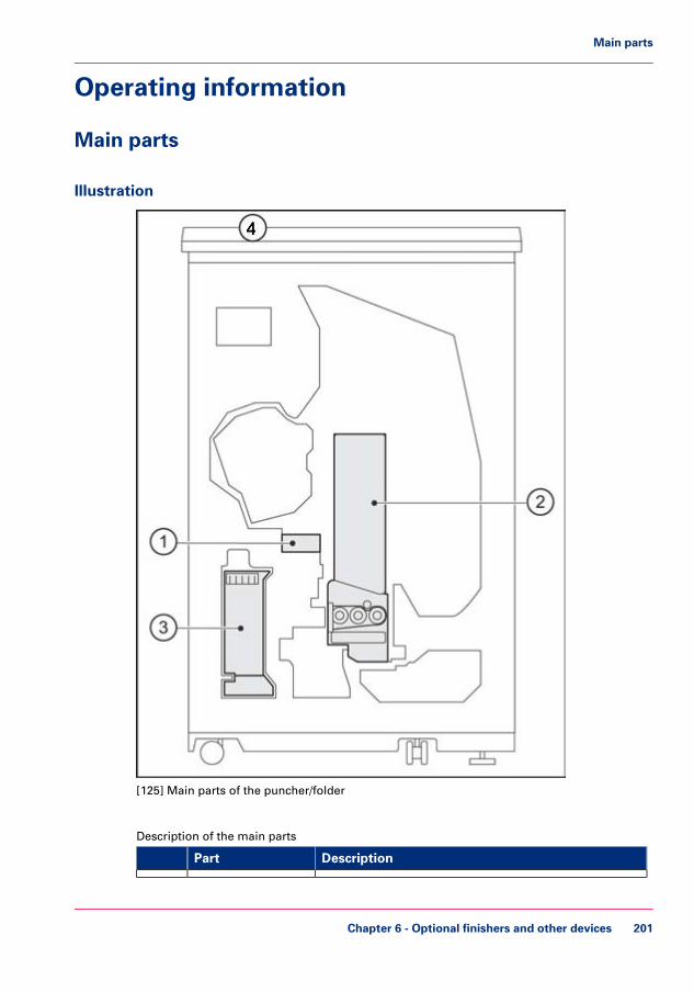
Operating information
Main parts
Illustration
[125] Main parts of the puncher/folder
Description of the main parts#
DescriptionPart
Chapter 6 - Optional finishers and other devices 201
Main parts

DescriptionPart
1 The puncher will be for 2 or 4 holes (A4 and A3 me-dia), or 2 or 3 holes (Letter and Ledger media), depend-ing upon the configuration ordered.
Puncher
The folder can half-fold or z-fold your documentsFolding unit2
The waste box collects the paper chads that arise fromthe punching process. You can easily access and emptythe waste box (see ‘Empty the waste box’ on page 205).
Waste box3
The output location for error pages.Top tray4
Chapter 6 - Optional finishers and other devices202
Main parts

Output locations
Introduction
If a stack of folded sheets is too high, the stack will tilt. Therefore, the system limits thenumber of folded sheets per output location. How the system limits the output capacitydepends on the folding method.
Z-fold• Depends on media weight and type.• Depends on the percentage of folded sheets in a stack.
Half-fold• Determined by a fixed number of folded sheets.
The default settings guarantee safe stacking for media up to 100 g/m² or 27 lb. bond forplain media or 120 g/m² or 32 lb. bond for coated media. You can adjust the stack heightfor heavier media in the Settings Editor. You can change the stack height in incrementsof 10% from -50% to +200%. For heavier media, start with -50% to prevent stacks tilting.
The table below gives an overview of the default capacity per output location for half-folded and Z-folded sheets.
Z-foldOutput capacity for Z-folded sheets#
Finisher (number of sheets)Stacker (number of sheets)Percentage offolded sheets(%)
400060001
300032002
225019803
132010805
51040010
27328014
14416025
Chapter 6 - Optional finishers and other devices 203
Output locations

Half-foldOutput capacity for half-folded sheets#
Finisher (number of sheets)Stacker (number of sheets)
12080
Chapter 6 - Optional finishers and other devices204
Output locations

Empty the waste box
Introduction
The waste box contains the paper chips that result from the punching process. The wastebox is located at the lower left-hand side of the puncher/folder (see ‘Main parts’ on page201).
When to do
The printer stops when the waste box is full. The operator panel displays a message. Themessage asks you to empty the waste box of the puncher/folder.
Illustration
[126] Location of the waste box
Empty the waste box
1. Open the front door of the puncher/folder.2. Pull out the waste box.3. Empty the waste box.4. Push the waste box back into place.
Chapter 6 - Optional finishers and other devices 205
Empty the waste box

5. Close the front door of the puncher/folder.
Chapter 6 - Optional finishers and other devices206
Empty the waste box

Clear a paper jam
Introduction
The puncher/folder has a very efficient and reliable paper jam recovery. When a paperjam occurs in the paper path of the puncher/folder, the operator panel displays the actionsyou must take to clear the paper jam. Error pages will be delivered to the top tray of thepuncher/folder.Besides a paper jam in the paper path of the puncher/folder, it is also possible that a paperjam occurs in the folding unit. This section describes the actions you must take to solvea paper jam in the folding unit.
Access the folding unit#
IllustrationActionStep
Open the front door of thepuncher/folder.
1
[127]
Lift the handle and pull out thefolding unit.
2
Chapter 6 - Optional finishers and other devices 207
Clear a paper jam

IllustrationActionStep
[128]
Lower the green bracket to re-lease the folding unit.
3
[129]
Turn the folding unit backwards.4
Clear a paper jam in the folding unit#
RemarksActionStep
Check the upper rollers for jammed me-dia.
1
Chapter 6 - Optional finishers and other devices208
Clear a paper jam

RemarksActionStep
[130]
Press the shaft located at the bottom ofthe folding unit to release the flap.
2
[131]
Slowly lower the flap with the rollers.
Note:If you lower the flap too fast, therollers may come loose. If theydo, you can simply push themback into position.
3
Check for jammed media.4
[132]
Push the flap with the rollers back intoplace by pressing the shaft.
5
Chapter 6 - Optional finishers and other devices 209
Clear a paper jam

Finish the procedure#
RemarksActionStep
[133]
Push the folding unit back intoits original position.
1
[134]
Push the green bracket back tosecure the folding unit.
2
Chapter 6 - Optional finishers and other devices210
Clear a paper jam
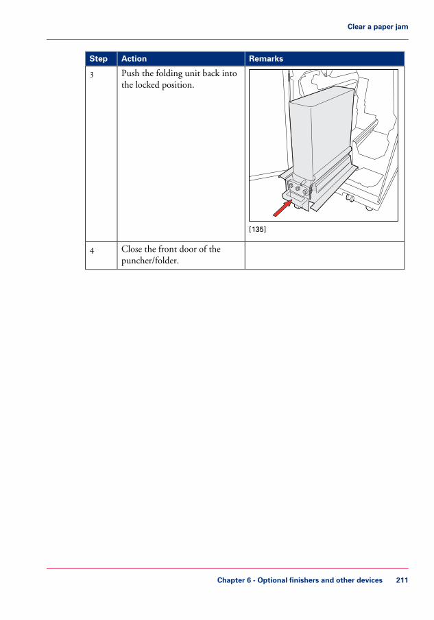
RemarksActionStep
[135]
Push the folding unit back intothe locked position.
3
Close the front door of thepuncher/folder.
4
Chapter 6 - Optional finishers and other devices 211
Clear a paper jam

Operating information
What is a folding shift and a folding skew?
Introduction
By default, the folder is adjusted to make a correct Z-fold.
However, if you use different types of media you can adjust the Z-fold in two ways:• Adjust the folding shift.• Adjust the folding skew.
This section describes the difference between a folding shift and a folding skew and howto make appropriate fold corrections.
Note:When your folded sheets show a folding skew and a folding shift, adjust the foldingskew first.
Description of a folding shift and a folding skew#
Folding skewFolding shift
Chapter 6 - Optional finishers and other devices212
What is a folding shift and a folding skew?

Folding skewFolding shift
If you want to change from a Z-fold to ahalf-fold or visa versa, it is possible for thefold line not to be exactly straight and foryour folded output to show a foldingskew.You can correct this folding skew usingthe knob in the puncher/folder (see ‘Ad-just the folding skew’ on page 214).
It is possible for the fold line not to beexactly in the in the middle of the sheet.If you have a job that contains both fold-ed and non-folded sheets, the result is thatthe folded sheets are slightly bigger thanyour non-folded sheets.You can correct this by adjusting the foldposition in the Settings Editor (see ‘Adjustthe folding shift’ on page 217).
Chapter 6 - Optional finishers and other devices 213
What is a folding shift and a folding skew?

Adjust the folding skew
Introduction
By default, the puncher/folder is set to Z-fold. If you switch to half-fold, it is possible foryour sheets to show a folding skew. You can correct this folding skew using the knobunderneath the left-hand top cover of the puncher/folder. If you switch back to Z-fold,you can turn the knob until you have reached the default position. You can find this defaultposition on the sticker inside the puncher/folder.
Folding skew correction
The following table gives an overview of the relation between the number of completerotations of the knob and the amount corrected in millimeters.
Folding skew correction#
Correction (in rotations)Folding skew error (mm)
1.50.5
[138] A folding skew
31.0
4.51.5
62.0
7.52.5
93.0
Chapter 6 - Optional finishers and other devices214
Adjust the folding skew

Adjust the folding skew#
RemarksActionStep
[139] Sticker inside puncher/folder
The black line at the left-hand side of thesticker indicates the default position. Thesticker also indicates in which directionyou should turn the knob to correct theskew.
Open the top covers of thepuncher/folder
1
Chapter 6 - Optional finishers and other devices 215
Adjust the folding skew

RemarksActionStep
[140]
If the skew is in this direction, turn theknob counter-clockwise.
Adjust the folding skew by turn-ing the knob.
2
[141]
If the skew is in this direction, turn theknob clockwise.
Close the top covers of thepuncher/folder.
3
Check the adjustments youmade.
4
Chapter 6 - Optional finishers and other devices216
Adjust the folding skew

Adjust the folding shift
Introduction
It can occur that the fold line is not exactly in the correct position. In that case, thefolded output shows a folding shift. If you have a job that contains both folded and non-folded sheets, the result is that the folded sheets are slightly bigger than the non-foldedsheets. You can correct this by adjusting the fold position in the Settings Editor.
Note:The folder has two fold plates, referred to as 1 and 2 in the text below.
Corrections for half-fold
If the folded sheets show a folding skew and a folding shift, adjust the folding shift first.
Chapter 6 - Optional finishers and other devices 217
Adjust the folding shift

#
ThenWhen
Decrease the fold position 1 with half thefolding shift
Increase the fold position 1 with half thefolding shift
Chapter 6 - Optional finishers and other devices218
Adjust the folding shift

Corrections for Z-fold#
ThenWhenStep
1
Increase fold position 2 with the de-sired length change.
You want to decrease the length ofthe shaded part.
Decrease fold position 2 with thedesired length change.
You want to increase the length ofthe shaded part.
Chapter 6 - Optional finishers and other devices 219
Adjust the folding shift

ThenWhenStep
Decrease the fold position 1 and 2with half the folding shift
2
Increase the fold position 1 and 2with half the folding shift
Adjust the folding shift
1. Go to the Settings Editor - 'Preferences' - 'Print job defaults' - 'Puncher/folder (iP&F)'.2. Click the pencil behind the individual settings to adjust the fold positions (in 0.1 mm
increments):• 'Adjustment for fold position 1' (first fold for Z-fold and half-fold)• 'Adjustment for fold position 2' (second fold for Z-fold only)
Chapter 6 - Optional finishers and other devices220
Adjust the folding shift

Puncher replacement
Replace the puncher
Introduction
Please contact your supplier for a replacement puncher if the old one becomes worn out.
This section describes how to remove the old puncher and install a new puncher.
When to do
Only replace a puncher when the printer is on hold.
Required tool• Number 10 socket wrench (supplied with the printer)
Access the folding unit#
IllustrationActionStep
Open the front door of thepuncher/folder.
1
[148]
Lift the handle and pull out thefolding unit.
2
Chapter 6 - Optional finishers and other devices 221
Replace the puncher

IllustrationActionStep
[149]
Lower the green bracket to re-lease the folding unit.
3
[150]
Turn the folding unit backwards.4
Chapter 6 - Optional finishers and other devices222
Replace the puncher

Replace the punch kit#
RemarksActionStep
[151]
Loosen and remove the 4 screwsof the puncher, and disconnectthe connector.
1
[152]
Pull the puncher out.3
Chapter 6 - Optional finishers and other devices 223
Replace the puncher

RemarksActionStep
[153]
Push the new puncher intoplace.
Note:Use an alignment pin toensure correct position-ing.
4
[154]
Fasten the 4 screws of thepuncher and connect the connec-tor .
5
Chapter 6 - Optional finishers and other devices224
Replace the puncher

Finish the procedure#
RemarksActionStep
[155]
Push the folding unit back in itsoriginal position.
1
[156]
Push the green tab back to securethe folding unit.
2
Chapter 6 - Optional finishers and other devices 225
Replace the puncher

RemarksActionStep
[157]
Push back the folding unit.3
Close the front door of thepuncher/folder.
4
Chapter 6 - Optional finishers and other devices226
Replace the puncher

Specifications
Main specifications#
SpecificationsItem
230 V, 50 Hz, single phase or 115 V, 60 Hz, single phasePower supply
1135 mm x 725 mm x 750 mm / 44.7" x 28.5" x 29.5"Dimensions H x D x W
180 kg / 397 lbs.Weight
Main specifications of the puncher#
SpecificationsItem
All media that the printer supports, including tabs.
Note:Punching positions are fixed.
Supported media sizes
50 g/m² to 210 g/m² / 14 lb. bond to 56 lb. coverSupported mediaweights
2 or 4 holes A4/A3 puncher:• 6.0 mm
2 or 3 holes Letter/Ledger puncher:• 2 holes - 0.25"• 3 holes - 0.31"
Hole punch size
1 sheetPunch capacity
Maintains print engine speedPunch speed
Main specifications of the folder#
SpecificationsItem
Minimum: 390 mm x 216 mm (15.5" x 8.5")Maximum: 432 mm x 305 mm (17" x 12")
Supported media sizes
70 g/m² to 100 g/m²18 lb. Bond to 26 lb. Bond
Supported mediaweights
Plain, satinated, glossy, silkSupported media types
Chapter 6 - Optional finishers and other devices 227
Specifications

SpecificationsItem
Maintains print engine speedFold speed
Z-foldHalf-fold
Folding methods
Chapter 6 - Optional finishers and other devices228
Specifications

Form Assist Module
Form Assist Module
Introduction
The printer allows you to print on special media with irregular thickness. Examples ofsuch media are media with glued-on (membership or bank) passes, folded media, or mediawith a slip attached. When you load a stack of special media with irregular thickness intothe paper tray, the stack will tilt. When the stack tilts too much, it may cause paper jams.Therefore, you can only load a limited amount of special media with irregular thicknessinto the paper tray.The Form Assist Module is a device you can insert in your paper tray without modifyingyour paper tray. It allows you to increase the media input capacity. When you use theForm Assist Module, your stack of special media will stay straight. This allows you toload more media into the paper tray and to increase your productivity. The Form AssistModule is delivered with 'Installation instructions'.
Caution:The variety of special media makes it difficult to predict whether the printer can processthe special media you want to use. Before you begin, test the special media and print alimited number of sheets.
Chapter 6 - Optional finishers and other devices 229
Form Assist Module

Paper input capacity#
Paper tray without Form As-sist Module
Paper tray with Form AssistModule
20 - 50100 - 200Paper with irreg-ular thickness(number ofsheets)
Chapter 6 - Optional finishers and other devices230
Form Assist Module

EasyLift
EasyLift
Introduction
The EasyLift is a device that helps you to lift stacks of paper out of the stacker more eas-ily. The EasyLift is delivered with an 'Information sheet'.
Warning:The maximum lifting weight is 15 kg / 33 lb.Caution: this is only a guideline, the amount may be lower/higher depending on yourphysical strength.
Warning:Avoid physical injury. Bend you knees and keep your back straight when you use theEasyLift.
Maximum weight
The following table gives you an indication of the weight of the most common mediayou can lift with the EasyLift.
#
Number of sheets / weight in kg/lbsMedia
2000 sheets1000 sheets500 sheets100 sheets
10.0 kg / 22.0lbs
5.0 kg / 11.0lbs
2.5 kg / 5.5lbs
0.5 kg / 1.1lbs
A4 (80 gr)
Too heavy!10.0 kg / 22lbs
5.0 kg / 11.0lbs
1.0 kg / 2.2lbs
A3 (80 gr)
Chapter 6 - Optional finishers and other devices 231
EasyLift

Number of sheets / weight in kg/lbsMedia
2000 sheets1000 sheets500 sheets100 sheets
9.1 kg / 20.0lbs
4.5 kg / 10.0lbs
2.3 kg / 5.0lbs
0.5 kg / 1.0lbs
Letter (20 lbs)
11.6 kg / 25.5lbs
5.8 kg / 12.7lbs
2.9 kg / 6.4lbs
0.6 kg / 1.3lbs
Legal (20 lbs)
Too heavy!9.1 kg / 20.0lbs
4.5 kg / 10.0lbs
0.9 kg / 2.0lbs
Ledger (20 lbs)
Chapter 6 - Optional finishers and other devices232
EasyLift

Remote viewer
Remote viewer
Introduction
The Remote Viewer gives you an overview of the printer status. It also displays how longthe printer can continue to print without operator intervention. The operator can seewhen intervention is needed, for example, when the printer runs out of paper. For confi-dentiality reasons, the viewer does not display job information.
The Remote Viewer is a web application. If your printer contains the optional RemoteViewer license, you can access the Remote Viewer via a URL in your a web browser.
Note:You can use the Remote Viewer when your printer has the optional Remote Viewer li-cense.When you enable the Remote viewer without a valid license, you receive a message thatno license is available.
Illustration
[160] The remote viewer
Alert functionality
The Remote viewer also offers an alert functionality. Your screen displays the Remoteviewer window on top when the printer status changes from:• 'Printing...' (alert light is green) to 'Stopped' (alert light is red), or• 'Printing...' (alert light is green) to Printing will stop...' (alert light is orange).
Chapter 6 - Optional finishers and other devices 233
Remote viewer

Specifications#
640 x 480 pixels or higherRecommended resolution of your comput-er screen
http://<printername>/remoteinfoURL to access Remote viewer
• Microsoft Internet Explorer 7+• Firefox 3+• Chrome• Safari
Supported web browsers
As defined in your browser, as long as theprinter supports this language
Language
Every 5 secondsUpdate frequency
Fixed (30 minutes)Time line
• Hostname• System mode• Status panel• Alert light• Operator instruction• Time line
Displayed printer information
Chapter 6 - Optional finishers and other devices234
Remote viewer

7" x 10" Statement Size Support
7" x 10" Statement Size Support
Introduction
The smallest media size that this machine supports is 203 x 203 mm / 7.9 x 7.9 inch.The 7" x 10" Statement Size Support device enables you to print on media with a size of7 x 10 inches / 178 x 254 mm.You can insert this device in your paper tray without modifying your paper tray. Thisdevice is delivered with 'Installation instructions'.
Note:If you want to print on 7 x 10 inch media, this media has to be available in the mediacatalog. If the media catalog does not contain the 7 x 10 inch media, you have to registerthis media first, (see ‘Perform a media registration for standard-size media’ on page 145).
Note:If you print on 7 x 10 inch media, it is important that the paper tray contains enoughmedia. The dashboard informs you when to load media.
Note:Remove the device from the paper tray, when you want to load other media than 7 x10 inch media.
How to load the media with the 7" x 10" Statement Size Support#
IllustrationAction
Open the paper tray1
Chapter 6 - Optional finishers and other devices 235
7" x 10" Statement Size Support

IllustrationAction
Flip the metal plates over to theright-hand side.
2
Load the media.3
Flip the metal plates over to the left-hand side over the media.
4
Close the paper tray5
Chapter 6 - Optional finishers and other devices236
7" x 10" Statement Size Support

Chapter 7Keeping the printer run-ning

Add toner
Introduction
This section describes how to add toner to the 2 toner reservoirs of the machine.
When to do
When a toner reservoir is empty or almost empty ‘Check the status of the toner reservoirs’on page 109.
Caution:Only use the Océ VarioPrint 6000 toner.
Caution:Never add more than 3 bottles at a time. The status bars of the toner indicators indicatethe amount of bottles you are allowed to fill.
Caution:The printer must be switched on to add the toner. You can add toner while the printeris busy.
Add toner
1. Shake the toner bottle well (see the instructions on the bottle).2. Remove the screw cap from the bottle.
Caution:Do not remove the seal from the bottle.
Chapter 7 - Keeping the printer running238
Add toner

3. Open the front door of the toner reservoir you want to fill.
[163] Open the front doors
4. Open the lid of the toner reservoir.5. Put the toner bottle into the opening of the toner reservoir.
Note:The toner bottle only fits one way.
6. When the toner bottle is empty, carefully tilt the toner bottle into the horizontal position.Make sure that the opening of the toner bottle remains over the opening of the tonerreservoir.
7. Rotate the toner bottle a half turn to the right to remove the residual toner.8. Remove the toner bottle.9. Close the lid of the toner reservoir.
10. Close the front door of the toner reservoir.
Chapter 7 - Keeping the printer running 239
Add toner

Finisher: Add staples
Introduction
The optional finisher ‘The output locations’ on page 33 on top of the stacker can stapleyour jobs. The finisher contains 2 staplers. Both staplers are located inside the finisher.Stapler 1 is located at the back side. Stapler 2 is located at the front side.This section describes how to add staples.
When to do
When a staple cartridge is empty or almost empty ‘Check the status of the staple cartridges’on page 111.
Note:You can add short and long staples. It is important to add the correct staples. Use shortstaples when your documents contain up to 50 sheets. Use long staples when your doc-uments contain more than 50 sheets. Only use staples of type S25 (long staples) or S37(short staples).
Get access to the staplers
1. Open the front door of the finisher.2. Open top cover E1.3. Open cover E5.4. Lock cover E5 with the locking mechanism E6.5. If required, slide stapler 1 to the center. This makes the access to the cartridge holder in
stapler 1 easier.
Add staples
1. Remove the cartridge holder from the stapler.
Chapter 7 - Keeping the printer running240
Finisher: Add staples

2. Press the striped release buttons at both sides of the cartridge holder to unlock the lowercover.
[164] Press the 2 release buttons simultaneously
The lower cover opens.
[165] The lower cover opens
Chapter 7 - Keeping the printer running 241
Finisher: Add staples

3. Remove the empty staple cartridge in the opposite direction of the arrow.
[166] Remove the staple cartridge
Chapter 7 - Keeping the printer running242
Finisher: Add staples

4. Slide a new staple cartridge into the cartridge holder, in the direction of the arrow.
[167] Place a new staple cartridge
Chapter 7 - Keeping the printer running 243
Finisher: Add staples

5. Push the staple cartridge into the cartridge holder until the cartridge clicks into place.
[168] Firmly push the staple cartridge into the holder
Chapter 7 - Keeping the printer running244
Finisher: Add staples
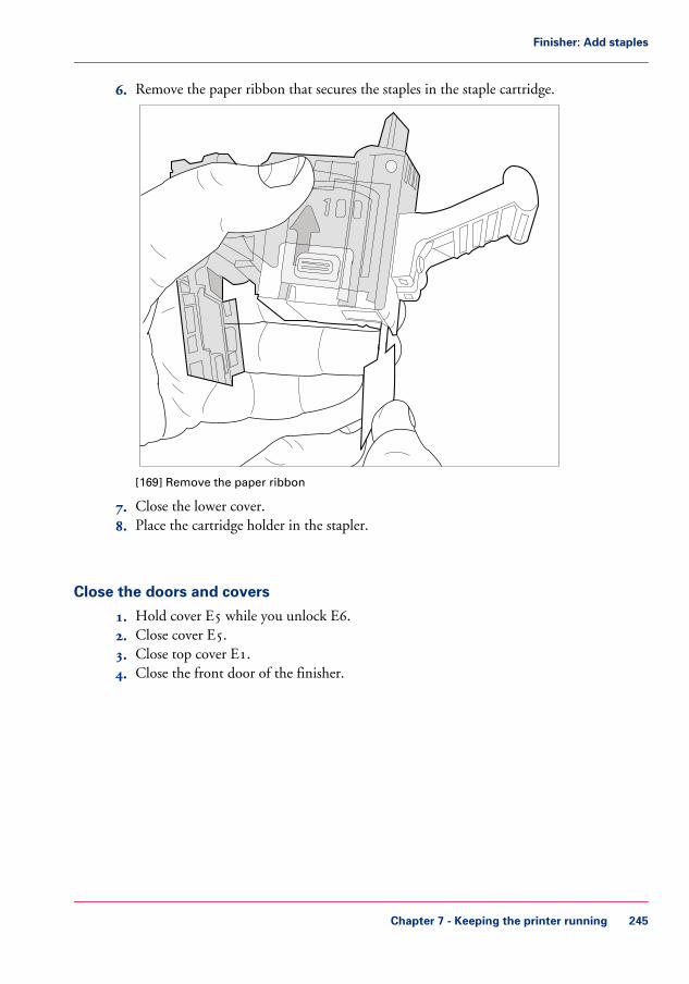
6. Remove the paper ribbon that secures the staples in the staple cartridge.
[169] Remove the paper ribbon
7. Close the lower cover.8. Place the cartridge holder in the stapler.
Close the doors and covers
1. Hold cover E5 while you unlock E6.2. Close cover E5.3. Close top cover E1.4. Close the front door of the finisher.
Chapter 7 - Keeping the printer running 245
Finisher: Add staples

Stacker/stapler (iMFS): Replace the staple cartridge
Introduction
The optional stacker/stapler (see ‘The output locations’ on page 33) contains 1 stapler thatcan put 1 or 2 staples into a document. This section describes how to replace the staplecartridge.
Note:Only use staples of type S36.
Replace the staple cartridge
1. Open the front side of the stacker/stapler.2. Pull the metal staple unit that contains the staple cartridge towards you.3. Push and hold the little amber lever to the left to unlock the staple unit.4. Pull the white, right-hand side of the staple unit towards you, at an angle of 90 degrees.5. Hold the little metal ridge at the top of the staple unit to prevent that the staple unit
slides to the front.6. Take the staple cartridge from the holder and insert a new staple cartridge.7. Push the little amber lever to the left to move the staple unit up again.8. Close the front side of the stacker/stapler.
Chapter 7 - Keeping the printer running246
Stacker/stapler (iMFS): Replace the staple cartridge

Troubleshooting
Introduction
The main types of possible errors are the following.• Errors that relate to the machine• Errors that relate to the jobs• Toner problems that relate to the use of fiber-rich media.
This section gives an overview of the possible errors and the solutions to these errors.
Note:Only operators who received the special maintenance training are allowed to replace orclean parts and solve paper jams in the process units.
Overview of the possible machine errorsHandle the machine errors#
Additional informationSolutionError
After you solved the error, the machinestarts from the point where the printingstopped due to the error. Please check fordouble prints.
Follow the instructionson the operator panel.
Paper jam
A message on the operator panel will indi-cate that you must restart the machine.
Follow the instructionson the operator panel.
Software error
A message on the operator panel will indi-cate that you must call Service.
Follow the instructionson the operator panel.
Service re-quired
The maintenance wizard appears. Youneed the maintenance PIN to access themaintenance mode. The machine is auto-matically switched off.
Note:Only trained operators are al-lowed to perform maintenancetasks.
Follow the instructionson the operator panel.
Maintenancerequired
Chapter 7 - Keeping the printer running 247
Troubleshooting
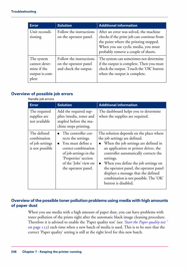
Additional informationSolutionError
After an error was solved, the machinechecks if the print job can continue fromthe point where the printing stopped.When you use cyclic media, you mustprobably remove a couple of sheets.
Follow the instructionson the operator panel.
Unit recondi-tioning
The system can sometimes not determineif the output is complete. Then you mustcheck the output. Touch the 'OK' buttonwhen the output is complete.
Follow the instructionson the operator paneland check the output.
The systemcannot deter-mine if theoutput is com-plete
Overview of possible job errorsHandle job errors#
Additional informationSolutionError
The dashboard helps you to determinewhen the supplies are required.
Add the required sup-plies (media, toner andstaples) before the ma-chine stops printing.
The requiredsupplies arenot available
The solution depends on the place wherethe job settings are defined.• When the job settings are defined in
an application or printer driver, thecontroller automatically corrects thesettings.
• When you define the job settings onthe operator panel, the operator paneldisplays a message that the definedcombination is not possible. The 'OK'button is disabled.
• The controller cor-rects the settings.
• You must define acorrect combinationof job settings in the'Properties' sectionof the 'Jobs' view onthe operator panel.
The definedcombinationof job settingsis not possible
Overview of the possible toner pollution problems using media with high amountsof paper dust
When you use media with a high amount of paper dust, you can have problems withtoner pollution of the prints right after the automatic black image cleaning procedure.Therefore it is advised to enable the 'Paper quality test' (see ‘Start the Paper quality test ’on page 133) each time when a new batch of media is used. This is to be sure that thecorrect 'Paper quality' setting is still at the right level for this new batch.
Chapter 7 - Keeping the printer running248
Troubleshooting

#
SolutionToner pollution problem
• Change the 'Paper quality' setting from 'Nor-mal' to 'Low' (see ‘Change the Paper quality ’on page 133).
• Use the 'Paper quality test' to determine if thisnew setting is the right cleaning mode for thismedia.
• The sheets of the 5th set must be totally tonerfree, also at the edges of the media size width.
• When these sheets still show toner pollution,you can set the 'Paper quality' setting to 'Lower'(see ‘Change the Paper quality ’ on page 133).
• Use the 'Paper quality test' to verify that thisnew setting is the right cleaning mode for thismedia.
Toner pollution on the firstsheets after the automatic blackimage cleaning procedure.
• Change the 'Paper quality' setting from 'Nor-mal' to 'Low' (see ‘Change the Paper quality ’on page 133).
• Use the 'Paper quality test' to determine if thisnew setting is the right cleaning mode for thismedia.
• The sheets of the 5th set must be totally tonerfree, also at the edges of the media size width.
• When these sheets still show toner pollution,you can set the 'Paper quality' setting to 'Lower'(see ‘Change the Paper quality ’ on page 133).
• Use the 'Paper quality test' to verify that thisnew setting is the right cleaning mode for thismedia.
Note:When the peripheral pollution mainlyoccurs at 1 side of the sheet, it is advisedto rotate the media in the paper tray by180 degrees.
Toner pollution on the firstsheets along the edge of the sheet(2-3 mm) after the automaticblack image cleaning procedure.
Chapter 7 - Keeping the printer running 249
Troubleshooting

SolutionToner pollution problem
• Change the 'Paper quality' setting from 'Nor-mal' to 'Low' (see ‘Change the Paper quality ’on page 133).
• Use the 'Paper quality test' to determine if thisnew setting is the right cleaning mode for thismedia.
• The sheets of the 5th set must be totally tonerfree, also at the edges of the media size width.
• When these sheets still show toner pollution,you can set the 'Paper quality' setting to 'Lower'(see ‘Change the Paper quality ’ on page 133).
• Use the 'Paper quality test' to verify that thisnew setting is the right cleaning mode for thismedia.
A combination of the above pol-lutions.
• Change the 'Paper quality' setting from 'Nor-mal' to 'Low' (see ‘Change the Paper quality ’on page 133).
• If the print quality is still not optimal with re-spect to mentioned ghost images, you can setthe 'Paper quality' setting to 'Lower' (see‘Change the Paper quality ’ on page 133).
Ghost images in mid and hightoner coverage areas.
Chapter 7 - Keeping the printer running250
Troubleshooting

Appendix AMiscellaneous

Product specifications
Note:The media specifications in the following table are based on plain paper of 80 g/m² or20 lb bond.
Overview of the main product specificationsProduct specifications#
SpecificationItem
Océ Gemini Instant Duplex technologyTechnology
Océ VarioPrint® 6160:• 170 images/minute (A4/Letter)• 88 images/minute (A3/Ledger)
Océ VarioPrint® 6200:• 200 images/minute (A4/Letter)• 106 images/minute (A3/Ledger)
Océ VarioPrint® 6250:• 250 images/minute (A4/Letter)• 132 images/minute (A3/Ledger)
Océ VarioPrint® 6320:• 314 images/minute (A4/Letter)• 168 images/minute (A3/Ledger)
Note:For 1-sided printing, the print speed ofA4 or Letter like media is 125 im-ages/minute for all machine types exceptfor the Océ VarioPrint® 6320. This ma-chine has a print speed of 157 images/perminute for 1-sided printing.
Print speed (2-sided)
• Minimum 8 x 8 inch• Maximum 12.5 x 19.2 inch
Supported media sizes
• 33 - 202 lb. bond for Océ recommended media• 40 - 135 lb. bond for other media
Supported media weights
Appendix A - Miscellaneous252
Product specifications

SpecificationItem
Long edge: maximum 19.1 inchesShort edge: maximum 12.5 inches
Printable area
< .02 inchesActive registration
• Normal trays 1 and 2:600 sheets each
• Bulk trays 3 and 4:1,700 sheets each
Input capacity per paper module
• Stacker:6,000 sheets in 2 stacks of 3,000 sheets each
• Finisher:Top tray: 900 sheetsMiddle tray: 1,000 sheets eachLower tray: 1,800 sheets.Upper output: 500 sheets
• Stacker/stapler:Output tray: 2,000 sheetsUpper output: 250 sheets
Output capacity per output loca-tion
• Stacker:All media sizes between 8 x 8 inch and 12.5 x19.2 inches
• Finisher:Long edge: 10.8 - 12.04 inchesShort edge: 8.18 - 8.66 inches
• Stacker/stapler, output tray (stapled sheets):Long edge: 203 mm - 488 mmShort edge: 203 mm - 297 mm
• Stacker/stapler, output tray (unstapled sheets):Long edge: 203 mm - 488 mmShort edge: 203 mm - 320 mm
• Stacker/stapler, upper output:Long edge: 178 mm - 488 mmShort edge: 203 mm - 320 mm
Supported media sizes per out-put location
• Finisher: 100 sheets• Stacker/stapler: 80 sheets. You can set a value
from 30 - 80 in the Settings Editor application
Stapling capacity
Océ VarioPrint 6000 tonerToner
Appendix A - Miscellaneous 253
Product specifications

SpecificationItem
• 1200 dpi• 180 lpi
Resolution
< 12 minutesWarm-up time
10/100 Mbit and 1 Gbit EthernetNetwork connectivity
• TCP/IP• IPX• SMB
Network protocols
• LPR/LPD for job submission• Socket printing• SNMP• IPP
Higher level protocols
• Adobe® PostScript® 3™ / streamingPostScript®
• PCL 6 (combines PCL5e and PCL XL)• PDF 1.6• Xerox® PPP support
Supported PDLs
• Océ VarioPrint® 6000 Ultra Line printerdriver
• Océ PRISMAprepare• Océ PRISMAaccess• Océ PRISMAproduction• Océ DPlink emulation of Xerox® DocuTech™
61xx (Xerox® DigiPath® 1.2, 2.0, 2.1, 3.x and4.x, and Xerox® FreeFlow™ 2.x)
• Kodak® KDK Link• EFI® Fiery Central
Supported applications
Appendix A - Miscellaneous254
Product specifications

Index
1-Sided printing1-Sided printing .............................................84
2-Sided printing2-Sided printing .............................................84
AAdd
Toner ...........................................................238Add staples
Finisher ........................................................240Stacker/stapler ..............................................246
Add temporary media to the Media catalogAdd temporary media to the Media catalog ...143
Add tonerAdd toner .....................................................238
Advanced media settingSetup section ................................................119
Advanced media settingsAdvanced media settings ...............................130
Advanced settingsPrint delivery settings ......................................87
ApplicationSupported .....................................................252
Assign buttonAssign button .................................................96
Assign media to paper trayAssign media to paper tray ..............................99
Available documentationAvailable documentation ................................17
BBilling counters
Billing counters ...................................116, 118Maintenance section .....................................114
BindingBinding ..........................................................90
BundleBundle ............................................................58Print jobs ........................................................72
Bundled jobsChange job settings .........................................72
CCapacity
Input ............................................................252Output ................................................203, 252
ChangeCheck first set .................................................78Image shift .............................................85, 170Language ......................................................126Media .............................................................94Number of sets ...............................................77Number of staples ...........................................90Offset stacking ................................................87Output location ..............................................87Page range ......................................................80Print order ......................................................87Rotation .........................................................87Sheet order .....................................................87Sheet orientation ............................................87Sort by page ....................................................87Sort by set .......................................................87Warning time ...............................................128
Change mediaChange media .................................................99
CheckPuncher waste box ........................................113Staple cartridges ...........................................111Toner level ...................................................109Waste box ....................................................113
Check first setCheck first set .................................................78Workflow .....................................................121
Clean the operator panelClean the operator panel .................................28
CombinePrint jobs ........................................................72
Configuration reportPrint .............................................................136
Confirm start of jobWorkflow .....................................................121
ConnectivityDefault gateway ............................................136DHCP .........................................................136DNS suffix follows domain ..........................136Host name ....................................................136Link speed and connection type ...................136MAC address ................................................136Primary DNS suffix ......................................136Subnet mask .................................................136
255
Index

TCP/IP ........................................................136Test TCP/IP connection ..............................136
Content of the manualsContent of the manuals ..................................17
Contradiction handlingContradiction handling ..................................76
CopyPrinted jobs ....................................................61
CountersCounters .............................................116, 118
CreateHotfolder .....................................................103Hotfolder default ticket ................................106
DDashboard
Dashboard ......................................................40Datadump file
Save ..............................................................136Date and time
Date and time ..............................................136Day counters
Day counters .......................................116, 118Maintenance section .....................................114Reset ............................................................116
Default gatewayDefault gateway ............................................136
Define job settingsHotfolder .....................................................106
DeletePrinted jobs ....................................................61Scheduled jobs ................................................56Waiting jobs ...................................................58
Delete jobsAll jobs ...........................................................67Jobs with available media ................................67Jobs with label ................................................67List of Printed jobs .........................................67List of Scheduled jobs .....................................67List of Waiting jobs ........................................67New jobs ........................................................67One by one .....................................................67Printed jobs ....................................................67
Destination of print jobWorkflow .....................................................121
DHCPDHCP .........................................................136
Die setsDie sets available ..........................................185
Inspect ..........................................................191Install ...........................................................189Lubricate the felt oil pad ...............................194Lubricate the punch pins ..............................194Lubricate the shoulder bolts and springs .......194Remove ........................................................189Replace .........................................................189
DNS suffix follows domainDNS suffix follows domain ..........................136
Double-sheet detectionDouble-sheet detection .................................130Disable .........................................................132Enable ..........................................................132
EEasyLift
EasyLift ........................................................231Eject a stack
After a set .......................................................52As soon as possible ..........................................52
EnableSeparator sheet ................................................81
Engine moduleEngine module ...............................................26
Enhanced media modeEnhanced media mode .................................130Disable .........................................................132Enable ..........................................................132
Error handlingOutput recovery ...........................................163
ErrorsJob errors ......................................................247Machine errors .............................................247
External finisherStatus ...........................................................108
FFace down
Face down ......................................................87Face up
Face up ...........................................................87Features
Features ..........................................................16Finisher
Finisher ..........................................................26First set
Check .............................................................78Fold
256
Index

Output ...........................................................91Fold the output
Fold the output ..............................................93Folding shift
Folding shift .................................................212Adjust ...........................................................217
Folding skewFolding skew ................................................212
Form Assist ModuleForm Assist Module .....................................229
HHeader down
Header down ..................................................87Header up
Header up ......................................................87Hold key
Operator panel ...............................................29Host name
Host name ....................................................136Hotfolder
Activate ........................................................102Create ...........................................................103Create shared network drive .........................104Default ticket ...............................................106Define job settings ........................................106Drag & drop ................................................101General information .....................................101Job settings ...................................................101Job ticket ......................................................101Link to automated workflow ........................103
IImage shift
Document printing mode ...............................85Transaction printing mode ...........................170
InsertSeparator sheet ................................................81
Inspect the die setsInspect the die sets ........................................191
Intermediate check printIntermediate check print ..............................134Setup section ................................................119
InterruptInterrupt .........................................................66
IPDSOutput recovery ...........................................163
JJob
Change number of sets ...................................77Change the media ...........................................94Change the number of staples .........................90Check the first set ...........................................78Give priority ...................................................65Make a proof ..................................................70Print later .......................................................69Print the job parameters .................................71Rename ..........................................................82Reprint ...........................................................64Shift the image .......................................85, 170Ticket .............................................................71To top ............................................................65
Job nameChange ...........................................................82
Job name truncationSetup section ................................................119
Job settingsHotfolder .....................................................101
Jobs buttonOperator panel ...............................................29
Jobs viewOverview ........................................................55
Jobs with available mediaJobs with available media ................................74
Jobs with labelJobs with label ................................................74
KKey operator settings
Key operator settings ....................................136Knowledge base
Knowledge base ..............................................12
LLabel
Label ...............................................................74Language
Setup section ................................................119Large media
Large media ..................................................116Licenses
Software .......................................................136Link speed and connection type
257
Index

Link speed and connection type ...................136Load media
Load media .....................................................47Schedule view .................................................49
Local key operator settingsLocal key operator settings ............................136Setup section ................................................119
LoggingConfiguration report ....................................136Datadump file ..............................................136Trace file ......................................................136
Low power modeLow power mode ............................................20
Low temperature modeLow temperature mode .................................130Disable .........................................................132Enable ..........................................................132Pre-printed ...................................................130
MMAC address
MAC address ................................................136Machine
Shut down ......................................................24Sleep mode .....................................................24Turn on ..........................................................23Wake up .........................................................23
MaintenanceMaintenance section .....................................114
Maintenance sectionMaintenance section .....................................114Billing counters ............................................114Day counters ................................................114Maintenance .................................................114Toner counters .............................................114
Make a proofMake a proof ..................................................70
MediaAssign .............................................................99Change ....................................................94, 99Icons ...............................................................97Information ....................................................97Large ............................................................116Load ...............................................................49Registration ..................................................139Standard .......................................................116Supported size ..............................................252Supported weight .........................................252
Media catalog
Media catalog ......................................139, 141Media handling
Description ..................................................141Media message
General .........................................................172Tray-to-media mode .....................................174Tray-to-tray mode ........................................173
Media registrationLarge media ..................................................152Standard-size media ......................................145
Media sectionSystem view ..................................................139
Media settingsAdvanced ......................................................130
Meter readingsMeter readings ..............................................118
MoveMove ..............................................................56
NNetwork
Connectivity .................................................252Protocols ......................................................252
Next output trayWorkflow .....................................................121
Number of setsNumber of sets ...............................................77
Number of staplesChange ...........................................................90Used .............................................................108
OOffset stacking
Offset stacking ................................................87Changes in the Properties window ..................83Types ..............................................................83
OKBOKB ...............................................................12
On/Off buttonOn/Off button ...............................................20
Open buttonOpen button ..................................................96
Operator attention lightOperator attention light ...........................26, 31Status colors ...................................................31
Operator panelOperator panel ...............................................26Clean ..............................................................28
258
Index

Dashboard ......................................................40Hold key ........................................................29Jobs button .....................................................29Main components ...........................................28Release key .....................................................29Schedule button ..............................................29System button ................................................29Trays button ...................................................29
OutputCapacity .......................................................203Fold ................................................................93Locations ......................................................203Punch .............................................................92
Output locationOutput location ..............................................87
Output locationsExternal finisher .............................................33Finisher ..........................................................33Finisher upper output .....................................33Stacker ............................................................33Stacker/stapler ................................................33Stacker/stapler upper output ...........................33System output ................................................33
Output recoveryOutput recovery ...........................................163
PPage range
All pages .........................................................80Indicate the range ...........................................80
Paper jamPuncher/Folder ............................................207
Paper modulePaper module .................................................26Control panel .................................................36Green check mark ...........................................36LEDs ..............................................................36Not assigned button .......................................36Red arrows ......................................................36
Paper qualityPaper quality .......................................130, 133
Paper quality testPaper quality test ..........................................130Start .............................................................133Stop ..............................................................133
Paper trayPaper tray .......................................................96Media .............................................................99
Paper tray icons
Paper tray icons ..............................................97PDL
Supported .....................................................252Power modes
Power modes ..................................................20Power switch
Power switch ..................................................20Pre-printed
Low temperature mode .................................130Primary DNS suffix
Primary DNS suffix ......................................136Print
Print ...............................................................58All jobs ...........................................................74Job parameters ................................................71Job settings .....................................................71Jobs in list of Waiting jobs ..............................63Jobs with available media ................................74Jobs with label ................................................74Urgent job ......................................................66
Print a scheduled job laterPrint a scheduled job later ...............................69
Print delivery settingsAdvanced settings ...........................................87Offset stacking ................................................87Output location ..............................................87Print order ......................................................87Rotation .........................................................87Sheet order .....................................................87Sheet orientation ............................................87Sort by page ....................................................87Sort by set .......................................................87
Print jobsBundle jobs .....................................................72Split bundled jobs ...........................................72
Print nowPrint now .................................................56, 66
Print orderPrint order ......................................................87
Print to stacker/staplerPrint to stacker/stapler ....................................51
Printable areaPrintable area ...............................................252
Printed jobsOverview ........................................................55
Printer sectionExternal finisher ...........................................108Number of used staples ................................108Puncher waste box ........................................108Puncher/folder waste box .............................108
259
Index

Toner ...........................................................108Printer software
Version .........................................................136Priority for a job
Priority for a job .............................................65Product specifications
Product specifications ...................................252Proof
Proof ........................................................58, 70Properties
Printed jobs ....................................................61Scheduled jobs ................................................56Waiting jobs ...................................................58
ProtocolsProtocols ......................................................252
PunchOrientation .....................................................91Output ...........................................................91
Punch the outputPunch the output ............................................92
PuncherChip tray ......................................................187Die sets available ..........................................185iXDP ..............................................................26Lubricate ......................................................193Main parts ....................................................182Replace die set ..............................................189Specifications ................................................199Types of binding ..........................................185Waste box ....................................................113
Puncher/FolderAdjust the folding shift .................................217Adjust the folding skew ................................214Clear a paper jam .........................................207Main parts ....................................................201Output locations ..........................................203Replace the puncher .....................................221Specifications ................................................227Waste box ....................................................205
Puncher/folderWaste box ....................................................113
RRegistration
Media ...........................................................139Release key
Operator panel ...............................................29Remote viewer
Remote viewer ..............................................233
RenameJob ..................................................................82
Replace staple cartridge of stacker/staplerReplace staple cartridge of stacker/stapler .....246
Reprint a jobReprint a job ..................................................64
Reset day countersReset day counters ........................................116
Roll feederRoll feeder ......................................................26
RotationRotation .........................................................87
Run modeRun mode ......................................................20
SSchedule button
Operator panel ...............................................29Schedule view
Introduction ...................................................43Jobs pane ........................................................44load media ......................................................49Media toolbar .................................................45Output locations pane ....................................45Required media pane ......................................44Streaming jobs ................................................43Zoom control .................................................46
Schedule waiting jobsSchedule waiting jobs .....................................63
Scheduled jobsOverview ........................................................55
SelectAll jobs ...........................................................74Different media for job ...................................94Job ..................................................................74Jobs with available media ................................74Jobs with label ................................................74Printed jobs ....................................................61Scheduled jobs ................................................56Waiting jobs ...................................................58
Separator sheetsSeparator sheets ..............................................81
Serial numberSerial number ...............................................136
SetsNumber ..........................................................77
Settings EditorAccess through operator panel ......................136Change settings ............................................136
260
Index

View settings ................................................136Setup section
Setup section ................................................119Advanced media settings ...............................119Intermediate check print ..............................119Job name truncation .....................................119Language ......................................................119Local key operator settings ............................119Shut down system ........................................119Warning time ...............................................119Workflow .....................................................119Workflow profile ..........................................119
Sheet orderSheet order .....................................................87
Sheet orientationSheet orientation ............................................87
Shut downMachine .........................................................24
Shut down procedureShut down procedure .....................................24
Shut down systemSetup section ................................................119
Sleep modeSleep mode ..............................................20, 24
SoftwareLicenses ........................................................136
Sort by pageSort by page ....................................................87
Sort by setSort by set .......................................................87
SplitSplit ................................................................58Print jobs ........................................................72
SRA controllerMissing media ..............................................172
StackerStacker ............................................................26Eject a stack ....................................................52Eject button ....................................................52
Stacker/stapleriMFS ..............................................................26Media orientation ...........................................51
Stacking methodStacking method .............................................83
Stand-by modeStand-by mode ...............................................20
Standard mediaStandard media ............................................116
StapleStatus ...........................................................111
Staple cartridgesStaple cartridges ...........................................111
Stapler iconsStapler icons .................................................111
StaplesStaples ............................................................90Finisher ........................................................240Stacker/stapler ..............................................246
StatusStatus ..............................................................40
Stop a jobAfter a job .......................................................53After a page .....................................................53After a set .......................................................53As soon as possible ..........................................53Streaming job .................................................54Transaction stream .........................................54
Stop after jobStop after job ..................................................56
Stop behaviorStop after a job ...............................................52Stop after a set ................................................52Stop as soon as possible ...................................52
Subnet maskSubnet mask .................................................136
SupportDownloads: ....................................................12Knowledge base ..............................................12Manuals ..........................................................12Media .............................................................12OKB ...............................................................12Printer drivers .................................................12Supplies ..........................................................12Toner .............................................................12
System administrator settingsSystem administrator settings .......................136
System buttonOperator panel ...............................................29
System componentsEngine module ...............................................26Finisher ..........................................................26Operator attention light ..................................26Operator panel ...............................................26Paper module .................................................26Puncher (iXDP) ..............................................26Roll feeder ......................................................26Stacker ............................................................26Stacker/stapler (iMFS) ....................................26
System of measurementSystem of measurement ................................136
261
Index

System settingsDate and time ..............................................136System of measurement ................................136Time zone ....................................................136
System viewMaintenance section .....................................114Media section ...............................................139Printer section ..............................................107Setup section ................................................119Transaction on-line ......................................168Transaction printing .....................................168Transaction section ..............................159, 168Transaction setup .........................................168
TTCP/IP
TCP/IP ........................................................136Temporary media
Temporary media .......................139, 142–143Test TCP/IP connection
Test TCP/IP connection ..............................136Ticket
Ticket ......................................................56, 71Printed jobs ....................................................61Waiting jobs ...................................................58
Time zoneTime zone ....................................................136
To topTo top .....................................................56, 65
TonerToner ...........................................................238Filling level ..........................................108–109Icon ..............................................................109Level .............................................................109
Toner counterToner counter .....................................116, 118
Toner countersMaintenance section .....................................114
Toner indicatorStatus bar .....................................................238Toner icon ...................................................238
Toner pollution problemsToner pollution problems .............................247
Trace fileSave ..............................................................136
TrademarksTrademarks .......................................................8
Trailer pageTrailer page ....................................................95
Media .............................................................95Transaction setups
Transaction setups ........................................175Tray
Load media .....................................................47Trays button
Operator panel ...............................................29Trays view
Overview ........................................................96Troubleshooting
Troubleshooting ...........................................247Turn on
Machine .........................................................23
UUrgent job
Urgent job ......................................................66
VVersion
Printer software ............................................136
WWaiting jobs
Overview ........................................................55Wake up
Machine .........................................................23Warm-up time
Warm-up time .............................................252Warning time
Warning time ...............................................128Disable .........................................................128Set ................................................................128Setup section ................................................119
Waste boxIcon ..............................................................113Puncher ........................................................113Puncher/folder .............................................113Status ..................................................108, 113
WorkflowCheck first set ...............................................121Confirm start of job .....................................121Destination of print job ................................121Next output tray ...........................................121Profile ..........................................................121Setup section ................................................119
Workflow profiles
262
Index

Check and print ...........................................122Function ......................................................121Job by job .....................................................122Manual planning ..........................................122Standard .......................................................122Unattended ..................................................122
263
Index

-
Beyond the Ordinary
oPrinting for
Professionals
Creating global leadership in printing
Canon and Océ have joined forces to create the global
leader in the printing industry. For our customers, this
combines Canon and Océ technology with the support
of the Océ direct sales and service organizations. Look
to the new Canon-Océ combination for:
• Enterprise printing in the office and corporateprintroom
• Large format printing of technical documentation,signage, and display graphics
• Production printing for marketing service bureaus andgraphic arts
• Business Services for document process outsourcing
For more information visit us at:
www.oce.com
©2006-2011Océ. Illustrations and specifications do not necessarily apply
to products and services offered in each local market. Technical
specifications are subject to change without prior notice. Trademarks
mentioned in this document are the property of their respective owners.
07-2011US
Related Documents


![Representations of Visual Appearance COMS 6160 [Fall 2006], Lecture 2 Ravi Ramamoorthi ravir/6160.](https://static.cupdf.com/doc/110x72/56649d3a5503460f94a14d5f/representations-of-visual-appearance-coms-6160-fall-2006-lecture-2-ravi.jpg)