Corrosion & Prevention 2015 Paper 109 - Page 1 COATING DETERIORATION AND CORROSION MECHANISMS IN LEACHING AND ADSORPTION TANKS IN GOLD MINING G. Harrison 1 , W. Gray 1 , P. Farinha 1 , M. Risbud 2 1. Extrin, Western Australia 2. Curtin University, Western Australia SUMMARY: Gold mine ore extractive leaching and adsorption processes generally occur in large volume steel tanks. The internal surfaces of the tanks used for these processes are exposed to corrosive environments, despite the basic pH conditions, due to a number of corrosion mechanisms. As such, corrosion rates of up to 12mm per year have been observed, leading to tank perforation and, in the extreme cases, failure. This paper draws on the authors combined experience gained from inspecting over 70 tanks over the course of 20 years, both in Australia and overseas. A study looking at forty two (42) tank inspection reports and associated site data was undertaken in order to identify the coating failure mechanisms and subsequent corrosion mechanisms within the tanks. The corrosion mechanisms identified in leaching and adsorption tanks in gold mining can be broken into groups, namely: chemical, mechanical, erosion, biological and galvanic. It was found that contamination of the substrate during preparation for protective coating application, impact damage and poor adhesion where the top three types of primary modes of coating failure mechanisms, comprising of 48% of the tanks inspected. Once the coating had failed locally and exposed the steel, the top three corrosion mechanisms were impingement corrosion, chloride pitting and under film corrosion. Further analysis and discussion of this study into coating deterioration and corrosion mechanisms in leaching and adsorption tanks in gold mining is expanded upon in this paper as well as a number of recommendations in order to mitigate the risks of premature failure in the future. Keywords: Mining, Integrity, Reliability, Tank Inspection, Gold Leaching Tanks, Gold Adsorption Tanks. 1. INTRODUCTION Traditionally gold cyanidation tanks were not coated internally as it was believed that the high operating alkalinity (pH ≥ 9) would prevent corrosion of the steel tank. Due to this expectation, a number of leach and adsorption tanks remain uncoated to this day and are in reasonable condition; however there are many that have had severe corrosion losses and even catastrophic failures [1][2]. Around the 1980’s internal protective coatings started to be applied to the top wall strake of leaching and adsorption tanks as this is where the “tidal zone” existed. More recently, it has become industry best practice to apply a protective coating to the entire tank internals.

Welcome message from author
This document is posted to help you gain knowledge. Please leave a comment to let me know what you think about it! Share it to your friends and learn new things together.
Transcript

Corrosion & Prevention 2015 Paper 109 - Page 1
COATING DETERIORATION AND CORROSION
MECHANISMS IN LEACHING AND
ADSORPTION TANKS IN GOLD MINING
G. Harrison1, W. Gray
1, P. Farinha
1, M. Risbud
2
1. Extrin, Western Australia
2. Curtin University, Western Australia
SUMMARY: Gold mine ore extractive leaching and adsorption processes generally occur in large
volume steel tanks. The internal surfaces of the tanks used for these processes are exposed to corrosive
environments, despite the basic pH conditions, due to a number of corrosion mechanisms. As such,
corrosion rates of up to 12mm per year have been observed, leading to tank perforation and, in the
extreme cases, failure.
This paper draws on the authors combined experience gained from inspecting over 70 tanks over the
course of 20 years, both in Australia and overseas. A study looking at forty two (42) tank inspection
reports and associated site data was undertaken in order to identify the coating failure mechanisms and
subsequent corrosion mechanisms within the tanks. The corrosion mechanisms identified in leaching and
adsorption tanks in gold mining can be broken into groups, namely: chemical, mechanical, erosion,
biological and galvanic. It was found that contamination of the substrate during preparation for protective
coating application, impact damage and poor adhesion where the top three types of primary modes of
coating failure mechanisms, comprising of 48% of the tanks inspected. Once the coating had failed locally
and exposed the steel, the top three corrosion mechanisms were impingement corrosion, chloride pitting
and under film corrosion.
Further analysis and discussion of this study into coating deterioration and corrosion mechanisms in
leaching and adsorption tanks in gold mining is expanded upon in this paper as well as a number of
recommendations in order to mitigate the risks of premature failure in the future.
Keywords: Mining, Integrity, Reliability, Tank Inspection, Gold Leaching Tanks, Gold Adsorption
Tanks.
1. INTRODUCTION
Traditionally gold cyanidation tanks were not coated internally as it was believed that the high operating alkalinity (pH ≥ 9)
would prevent corrosion of the steel tank. Due to this expectation, a number of leach and adsorption tanks remain uncoated to
this day and are in reasonable condition; however there are many that have had severe corrosion losses and even catastrophic
failures [1][2]. Around the 1980’s internal protective coatings started to be applied to the top wall strake of leaching and
adsorption tanks as this is where the “tidal zone” existed. More recently, it has become industry best practice to apply a
protective coating to the entire tank internals.

Corrosion & Prevention 2015 Paper 109 - Page 2
Typically, the current maintenance procedure for internally coated Leach and Adsorption tanks is to empty each tank every two
to three (2-3) years for up to two months to carry out maintenance inspections and coating repairs to ensure the ongoing
reliability of the steel shell of the tanks. Over the last 20 or so years, the authors have engaged in numerous maintenance
inspections, in order to ascertain the internal condition and develop a scope of works for repairs. Analysis of the data collected
from these inspections has identified the most prevalent root causes of tank internal coating failures and associated corrosion
mechanisms. The results of the study have been summarised in this paper in an effort to improve future activities including
design, construction, maintenance and day to day operation of the tanks.
2. BACKGROUND
2.1 Description of Cyanidation Tanks
Gold cyanidation is the process of using cyanide as a complexing agent in conjunction with oxygen; an oxidising agent,
together, to stabilise gold ions in aqueous solution [3]. This process is often referred to as leaching. The leaching process
usually occurs in a gold processing plant in a number of large tanks (typically 8-14m in diameter and 8-14m high) that are
connected in series. Before entering the leaching circuit, the gold-rich ore is finely crushed and mixed with process water to
create a fine ore slurry. After a number of other gold rending processes, the ore slurry is fed to the leach tanks where it is
thoroughly mixed by large agitators and aerated by bubbling air or oxygen. Cyanide is generally added to the solution in the
form of Sodium Cyanide, as well as pH buffers to maintain an alkaline environment. The cyanide forms a complex with the
gold within the slurry and remains in solution in aqueous form. The dissolution of gold in aqueous solution involves oxidation
of gold into ionic species coupled with cyanide complexing to stabilize the gold ion in solution as per the Elsner equation
shown below in equation 1.
OHCNAuOHOCNAu 4])([4284 222 [eqn. 1]
In the adsorption tanks, activated carbon is added to the process and pumped counter current to the slurry. The cyanide gold
complex is adsorbed onto the activated carbon’s large surface area and this “loaded carbon” is collected in a screen and
removed for further processing to extract the gold.
Under agitation, the flow of the hard, sharp particles of fines in solution (slurry consistency is typically 80% pass at 150
microns) within the tanks is typically abrasive in nature, with areas of increased turbulent flow normally associated with baffles
and the baffle supports, both adjacent and directly below baffle plates.
In addition, many mine sites in the Australasian region are exposed to an inherently aggressive service water environment with
chloride levels in process water of between 50,000 – 75,000 ppm. As such, the means and methods for asset protection need to
be carefully considered, and more importantly, correctly implemented to prevent future deterioration.
2.2 Inspection of leaching tanks
The inspection methods used for each tank inspection varied depending on individual requirements. Generally the inspection
would involve the identification of coating and steel defects via visual inspection, sampling and data collection followed by
analytical testing as necessary. The end result was a report that detailed a scope for repair (mechanical and coatings) as well as
information on the mechanisms of deterioration.
Before the inspection, the tanks are generally fully cleaned with high pressure water. An elevated work platform (EWP) is
typically installed for inspection at heights. As the tanks are considered a confined space, gas testing is carried out before entry.
Whilst onsite a visual inspection of the tanks walls, floors and other internal fixtures is undertaken, noting any anomalies in the
coating (i.e. mechanical damage, blisters, cracks, localised metal loss etc.). A comment is provided on the surface preparation
and coating application quality to the tank. Following the visual inspection, sites are selected for analytical testing of the tanks
walls, floors and other internal fixtures at selected locations. To assist with reporting, any historical technical information
available is also gathered such as coating specifications, quality assurance data, drawings, tank slurry
parameters/characteristics, etc. During these inspections, the modes of degradation or corrosion mechanisms are of particular
interest, with the dimensions of the corrosion damage and morphology recorded.
3. COATING DETERIORATION
The primary form of corrosion protection in leaching and adsorption tanks today is barrier coatings. The properties of these
coatings have to be flexible enough to account for the dynamic conditions in the tank walls as they are filled and emptied; it has
to aim to stop the transmission of water through the coating and has to be abrasion and impact resistant.
Corrosion to the coated carbon steel shell of the tank is a result of defects in and/or damage to the protective coating in a highly
aggressive environment. Due to corrosivity of the process and the abrasive nature of the slurry, rapid coating deterioration,

Corrosion & Prevention 2015 Paper 109 - Page 3
corrosion and tank perforation will result wherever coating defects, damage and/or degradation results in a failure of the
coating barrier.
Review of the inspection data from 42 leaching and adsorptions tanks, located in the Australasian region, revealed some
interesting trends in coating deterioration mechanisms. The majority of the instances of coating damage, both reported by asset
owners and those observed by the authors, appear to be due to a combination of factors. The factors have been sorted into
categories and listed in order of prevalence in Table 3 below.
Table 1 - Factors involved in coating failure.
Coating System Specifics
Inappropriate coating selection with regards to chemical and/or abrasion resistance
Specification of coating (Coating Type, Specified Dry Film Thickness, Blast profile and Cleanliness)
Incorrect mixing ratios of product
Coating Characteristics (Hardness, Permeability, Elongation Wear Resistance)
Storage of paints (Shelf life, Product identification labels, Batch numbers, Condition of storage packaging)
Coating application QAQC
Inadequate surface preparation with respect to surface cleanliness and surface profile, plus attention of rough surface (e.g. welds) and rounding of sharp
edges to minimise weak points in the coating.
Poor quality control in coating application resulting in pinhole defects and/or inadequate film thickness.
Blast profile, Cleanliness
Contamination of the product whilst spraying
Spray technique, coverage
“Overcoat windows” exceeded.
Inadequate Continuity Testing as per AS 3894.1, AS 3894.2
Dry Film Thickness to AS 3894.3
Cure to AS3894.4
Surface profile to AS3894.5
Residual contaminants to AS 3894.6, Contamination (Fe,Cl, pH)
Adhesion to AS 3894.9
Wet film Thicknesses -Regular wet film build thicknesses completed
Surface temperature and dew point to AS3894.7
Tank Internal Environment
Coating weakness on sharp edges and welds
Damage from foreign objects / Mechanical damage from foreign objects and heavy-handed workmanship.
Chemical parameters of Tank (Chloride content, pH, dissolved metals, Oxygen content (usually saturated)
Heat damage – External welding
Agitation characteristics, localised thinning in areas of high turbulence and slurry abrasion on the floor and wall
High work index of the slurry, Sharpness (particle roughness), Specific gravity
Number of plates/repairs on the tanks wall and floor
Surface condition/level of pitting as a result of no coating being applied or failures in existing coating
Tank design - Baffle design, Launder design, Dimensions of the tank
Repairs/maintenance regime
How regularly the tank is emptied and cleaned for inspection?
Is the inspection carried out by the asset owner, consultant or contractor?
3.1 Top three (3) coating deterioration mechanisms explained
3.1.1 Blistering
Blistering, as the name suggests, are bubbled areas of coating, usually fluid filled. Blisters can be a result of a number of root
causes including solvent entrapment, osmosis, soluble salt contamination, off-ratio mixing, weld undercut, porosity and
crevices, etc. The most prevalent form of blistering is osmotic blistering which is generally indicative of poor surface
preparation and/or likely contamination on the steel substrate surface at the time of coating application.
Osmotic blisters contain moisture which is suggestive of soluble contamination or moisture being present on the metal surface
at the time of coating application. The mechanism that causes osmotic blistering is the same irrespective of the product.
Osmotic blistering requires the following: (1) a permeable film; (2) a relatively impermeable substrate; (3) water dissolved
solids; and (4) a concentration gradient [7]. The concentration gradient is the driving force for the creation and expansion of a
blister. Osmotic blistering has been related to chlorides, sulphates, and other inorganic soluble species often found on
substrates.
Such blistering can also be due to hydrophilic solvents and other diluents being entrapped in the coating film. If these products
are miscible with water, they could be drawn through the film osmotically. A greater concentration then occurs at the interface
which needs to be compensated by an osmotic pressure, allowing more water through the film to reduce the concentration at the
interface.
Corrosion & Prevention 2015 Paper 109 - Page 4
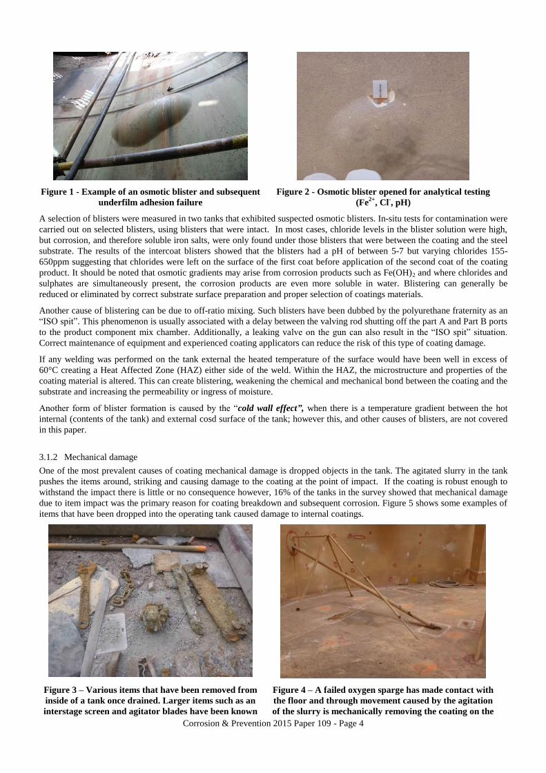
Figure 1 - Example of an osmotic blister and subsequent
underfilm adhesion failure
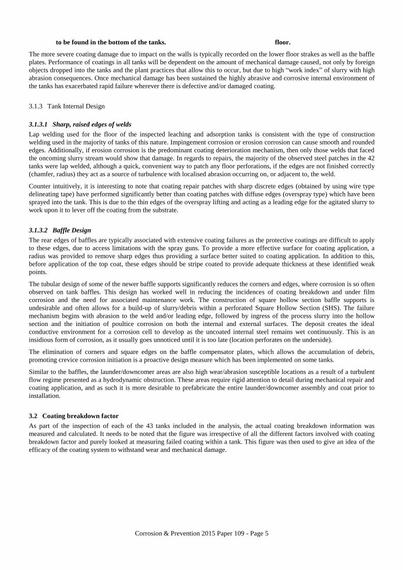
Figure 2 - Osmotic blister opened for analytical testing
(Fe2+
, Cl-, pH)
A selection of blisters were measured in two tanks that exhibited suspected osmotic blisters. In-situ tests for contamination were
carried out on selected blisters, using blisters that were intact. In most cases, chloride levels in the blister solution were high,
but corrosion, and therefore soluble iron salts, were only found under those blisters that were between the coating and the steel
substrate. The results of the intercoat blisters showed that the blisters had a pH of between 5-7 but varying chlorides 155-
650ppm suggesting that chlorides were left on the surface of the first coat before application of the second coat of the coating
product. It should be noted that osmotic gradients may arise from corrosion products such as Fe(OH)2 and where chlorides and
sulphates are simultaneously present, the corrosion products are even more soluble in water. Blistering can generally be
reduced or eliminated by correct substrate surface preparation and proper selection of coatings materials.
Another cause of blistering can be due to off-ratio mixing. Such blisters have been dubbed by the polyurethane fraternity as an
“ISO spit”. This phenomenon is usually associated with a delay between the valving rod shutting off the part A and Part B ports
to the product component mix chamber. Additionally, a leaking valve on the gun can also result in the “ISO spit” situation.
Correct maintenance of equipment and experienced coating applicators can reduce the risk of this type of coating damage.
If any welding was performed on the tank external the heated temperature of the surface would have been well in excess of
60°C creating a Heat Affected Zone (HAZ) either side of the weld. Within the HAZ, the microstructure and properties of the
coating material is altered. This can create blistering, weakening the chemical and mechanical bond between the coating and the
substrate and increasing the permeability or ingress of moisture.
Another form of blister formation is caused by the “cold wall effect”, when there is a temperature gradient between the hot
internal (contents of the tank) and external cosd surface of the tank; however this, and other causes of blisters, are not covered
in this paper.
3.1.2 Mechanical damage
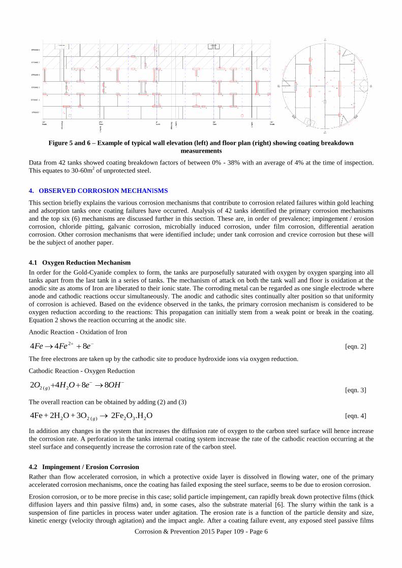
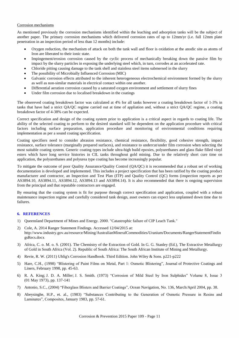
One of the most prevalent causes of coating mechanical damage is dropped objects in the tank. The agitated slurry in the tank
pushes the items around, striking and causing damage to the coating at the point of impact. If the coating is robust enough to
withstand the impact there is little or no consequence however, 16% of the tanks in the survey showed that mechanical damage
due to item impact was the primary reason for coating breakdown and subsequent corrosion. Figure 5 shows some examples of
items that have been dropped into the operating tank caused damage to internal coatings.
Figure 3 – Various items that have been removed from
inside of a tank once drained. Larger items such as an
interstage screen and agitator blades have been known
Figure 4 – A failed oxygen sparge has made contact with
the floor and through movement caused by the agitation
of the slurry is mechanically removing the coating on the
Corrosion & Prevention 2015 Paper 109 - Page 5
to be found in the bottom of the tanks. floor.
The more severe coating damage due to impact on the walls is typically recorded on the lower floor strakes as well as the baffle
plates. Performance of coatings in all tanks will be dependent on the amount of mechanical damage caused, not only by foreign
objects dropped into the tanks and the plant practices that allow this to occur, but due to high “work index” of slurry with high
abrasion consequences. Once mechanical damage has been sustained the highly abrasive and corrosive internal environment of
the tanks has exacerbated rapid failure wherever there is defective and/or damaged coating.
3.1.3 Tank Internal Design
3.1.3.1 Sharp, raised edges of welds
Lap welding used for the floor of the inspected leaching and adsorption tanks is consistent with the type of construction
welding used in the majority of tanks of this nature. Impingement corrosion or erosion corrosion can cause smooth and rounded
edges. Additionally, if erosion corrosion is the predominant coating deterioration mechanism, then only those welds that faced
the oncoming slurry stream would show that damage. In regards to repairs, the majority of the observed steel patches in the 42
tanks were lap welded, although a quick, convenient way to patch any floor perforations, if the edges are not finished correctly
(chamfer, radius) they act as a source of turbulence with localised abrasion occurring on, or adjacent to, the weld.
Counter intuitively, it is interesting to note that coating repair patches with sharp discrete edges (obtained by using wire type
delineating tape) have performed significantly better than coating patches with diffuse edges (overspray type) which have been
sprayed into the tank. This is due to the thin edges of the overspray lifting and acting as a leading edge for the agitated slurry to
work upon it to lever off the coating from the substrate.
3.1.3.2 Baffle Design
The rear edges of baffles are typically associated with extensive coating failures as the protective coatings are difficult to apply
to these edges, due to access limitations with the spray guns. To provide a more effective surface for coating application, a
radius was provided to remove sharp edges thus providing a surface better suited to coating application. In addition to this,
before application of the top coat, these edges should be stripe coated to provide adequate thickness at these identified weak
points.
The tubular design of some of the newer baffle supports significantly reduces the corners and edges, where corrosion is so often
observed on tank baffles. This design has worked well in reducing the incidences of coating breakdown and under film
corrosion and the need for associated maintenance work. The construction of square hollow section baffle supports is
undesirable and often allows for a build-up of slurry/debris within a perforated Square Hollow Section (SHS). The failure
mechanism begins with abrasion to the weld and/or leading edge, followed by ingress of the process slurry into the hollow
section and the initiation of poultice corrosion on both the internal and external surfaces. The deposit creates the ideal
conductive environment for a corrosion cell to develop as the uncoated internal steel remains wet continuously. This is an
insidious form of corrosion, as it usually goes unnoticed until it is too late (location perforates on the underside).
The elimination of corners and square edges on the baffle compensator plates, which allows the accumulation of debris,
promoting crevice corrosion initiation is a proactive design measure which has been implemented on some tanks.
Similar to the baffles, the launder/downcomer areas are also high wear/abrasion susceptible locations as a result of a turbulent
flow regime presented as a hydrodynamic obstruction. These areas require rigid attention to detail during mechanical repair and
coating application, and as such it is more desirable to prefabricate the entire launder/downcomer assembly and coat prior to
installation.
3.2 Coating breakdown factor
As part of the inspection of each of the 43 tanks included in the analysis, the actual coating breakdown information was
measured and calculated. It needs to be noted that the figure was irrespective of all the different factors involved with coating
breakdown factor and purely looked at measuring failed coating within a tank. This figure was then used to give an idea of the
efficacy of the coating system to withstand wear and mechanical damage.
Corrosion & Prevention 2015 Paper 109 - Page 6
Figure 5 and 6 – Example of typical wall elevation (left) and floor plan (right) showing coating breakdown
measurements
Data from 42 tanks showed coating breakdown factors of between 0% - 38% with an average of 4% at the time of inspection.
This equates to 30-60m2 of unprotected steel.
4. OBSERVED CORROSION MECHANISMS
This section briefly explains the various corrosion mechanisms that contribute to corrosion related failures within gold leaching
and adsorption tanks once coating failures have occurred. Analysis of 42 tanks identified the primary corrosion mechanisms
and the top six (6) mechanisms are discussed further in this section. These are, in order of prevalence; impingement / erosion
corrosion, chloride pitting, galvanic corrosion, microbially induced corrosion, under film corrosion, differential aeration
corrosion. Other corrosion mechanisms that were identified include; under tank corrosion and crevice corrosion but these will
be the subject of another paper.
4.1 Oxygen Reduction Mechanism
In order for the Gold-Cyanide complex to form, the tanks are purposefully saturated with oxygen by oxygen sparging into all
tanks apart from the last tank in a series of tanks. The mechanism of attack on both the tank wall and floor is oxidation at the
anodic site as atoms of Iron are liberated to their ionic state. The corroding metal can be regarded as one single electrode where
anode and cathodic reactions occur simultaneously. The anodic and cathodic sites continually alter position so that uniformity
of corrosion is achieved. Based on the evidence observed in the tanks, the primary corrosion mechanism is considered to be
oxygen reduction according to the reactions: This propagation can initially stem from a weak point or break in the coating.
Equation 2 shows the reaction occurring at the anodic site.
Anodic Reaction - Oxidation of Iron
eFeFe 844 2 [eqn. 2]
The free electrons are taken up by the cathodic site to produce hydroxide ions via oxygen reduction.
Cathodic Reaction - Oxygen Reduction
OHeOHO g 8842 2)(2 [eqn. 3]
The overall reaction can be obtained by adding (2) and (3)
O.HO2Fe 3O + O2H + 4Fe 232)(22 g [eqn. 4]
In addition any changes in the system that increases the diffusion rate of oxygen to the carbon steel surface will hence increase
the corrosion rate. A perforation in the tanks internal coating system increase the rate of the cathodic reaction occurring at the
steel surface and consequently increase the corrosion rate of the carbon steel.
4.2 Impingement / Erosion Corrosion
Rather than flow accelerated corrosion, in which a protective oxide layer is dissolved in flowing water, one of the primary
accelerated corrosion mechanisms, once the coating has failed exposing the steel surface, seems to be due to erosion corrosion.
Erosion corrosion, or to be more precise in this case; solid particle impingement, can rapidly break down protective films (thick
diffusion layers and thin passive films) and, in some cases, also the substrate material [6]. The slurry within the tank is a
suspension of fine particles in process water under agitation. The erosion rate is a function of the particle density and size,
kinetic energy (velocity through agitation) and the impact angle. After a coating failure event, any exposed steel passive films

Corrosion & Prevention 2015 Paper 109 - Page 7
are broken down through impact of the particles in solution with the steel surface. This is cyclic process of mechanically
breaking down the passive film exposing the underlying steel which, in turn, corrodes forming a new passive film.
The most severe corrosion in theory and in practice has been observed around the baffle plates where the impact angle and
velocity is strongly affected by turbulent flow characteristics. In 87% of the tanks inspected severe areas of localized corrosion
including the characteristic open, shallow metal loss areas and perforation were observed randomly at the baffles.
4.3 Pitting and perforation
Pitting was observed in 98% of all the tanks in the study of which 80% was due to pitting and crevice corrosion, exacerbated by
the presence of carbon on the metal surface and by abrasion and/or wear of the passive oxide film.
Water analysis of process water at 15 locations in Western Australia shows that process water, when compared with seawater,
has a higher salinity. Chlorides where found in the range of 50,000 to 75,000ppm compared with just less than 19,000ppm in
seawater. Sulphates where found in the range of 5,000 to 10,000ppm sulphate compared with about 2,600ppm in seawater.
Figure 7 – View shows minor pitting in an area of
increased velocity close to a baffle support. Image was
taken after abrasive cleaning
Figure 8 – 300mm x 300mm plate cut from tank floor to
ascertain if the perforation (white arrow) was due to
corrosion from the underfloor environment
As part of an investigation into perforation in tank floors, on six various sites, 300 x 300mm plates (figure 8) were cut from the
tank floor that included a perforation. These where used to determine if localised corrosion was also occurring from the
outside/in, or if the corrosion risk was predominantly from the inside/out. The samples were retained for testing and results
showed that 60% of the plates showed corrosion from the inside/out with the remainder being from the outside/in.
Further investigation into the high instance of outside/in perforation of the plates was carried out in the form of soil/backfill
testing underneath the tanks in the area cut out. Resistivity testing of the compacted sand tank base materials was performed
using a Wenner 4 pin procedure and a soil resistivity determined of 140-180 Ω-cm. This value is considered an extremely low
resistivity (a high conductivity) and suggests the floor backfill material has a severe corrosivity rating. Should moisture
penetration/saturation in the tank ring beam backfill increase, the corrosion risk from the outside/in would increase and this
would require careful corrosion management consideration.
4.4 Microbially Induced Corrosion (MIC)
Microbially Induced Corrosion (MIC) was found in 8% of the tanks inspected. MIC by Sulphate Reducing Bacteria (SRB) is a
corrosion mechanism in leaching and adsorption tanks that has been well documented. Widespread SRB activity over all
surfaces within the vessel is unlikely, since the oxygen sparging and tank agitation would keep many areas highly aerated and
free from deposits and. However, the likelihood of corrosion due to SRB would increase in areas where sludge and deposits can
form on horizontal surfaces or in areas of low flow, thus allowing an anaerobic micro-environment to develop. Once SRB
colonies start to develop, they will then establish their own anaerobic micro-environment.

Corrosion & Prevention 2015 Paper 109 - Page 8
Figure 9 – Stereotypical MIC tubercle formation on the
inside of a tank
Figure 10 - MIC damage evident underneath tubercle.
Image was taken after abrasive cleaning
It has been demonstrated that microbial corrosion occurs in a leaching and adsorption tank circuit, in those areas under deposits
and tubercles where anaerobic conditions can exist. This is particularly the case when sulphidic mineral ores are being
processed.
As the images above show, the morphology of attack associated with SRB (pitting corrosion) is such that a substrate can be
perforated in several locations with the parent plate immediately adjacent in good condition. This makes MIC difficult to
provide accurate corrosion rates that can be utilised to determine the time to perforation. Steel corrosion rates of 5-10mm per
annum have been recorded under these circumstances.
4.5 Galvanic Corrosion Effects
This section will discuss the three primary galvanic effects that accelerated corrosion within leaching and adsorption tanks.
These are; activated carbon cathode, stainless steel cathodes and other micro galvanic effects.
Other forms of localised galvanic effects have been observed such as the use of unsuitable weld consumables being used and
stainless steel bolts being inside the tank. In both cases, and indeed any other galvanic incompatibility issues, it is preferable to
ensure that the materials types used are similar to the steel shell parent plate in both specification and in application.
4.5.1 Activated Carbon Cathode
Activated Carbon is used in adsorption of the aqueous Gold-Cyanide complex in order to extract it from solution. The carbon is
ideal for this process due to its extremely large specific surface area to volume ratio. This large surface area is due to the highly
developed internal pore structure during thermal activation. This total exposed surface will typically be in the range of 800-
1200 m2/g [3].
Carbon forms a strong cathode due to its noble position on the galvanic series with respect to carbon steel (tank shell and
floor). According to the galvanic series, it can be seen that Graphite (carbon) has a potential +0.20V (S.C.E.) whereas carbon
steel has a -0.65V (S.C.E.). This potential difference of some 0.85V provides a considerable driving voltage for galvanic
corrosion to occur. This fact, coupled with the large surface area of the carbon granules, develops a very powerful galvanic cell.
4.5.2 Stainless steel cathodes
As previously mentioned, each tank is fitted with one or two screens that ensure carbon does not get transferred downstream in
the process. The screens are typically of stainless steel construction and utilise a stainless steel wedge wire mesh with an
aperture of 1.0mm to prevent the ingress of carbon particles and their migration with the slurry. Rotating wipers prevent
blocking of the mesh with the carbon granules.
Numerous steel repair patches were observed on the coated carbon steel tank, in close proximity to the screen. Excessive
localised corrosion on the uncoated carbon steel tank and interstage screen frame near the interface with the stainless is most
likely due to galvanically accelerated corrosion in the very conductive tank environment. On closer inspection of the tanks in
which this was observed, the tank and the inter-stage screen were not electrically isolated.
The total surface area of the Stainless Steel wedge wire screen and rotating cage assembly was calculated at about 43m2. The
corrosion current calculated based on this surface area equates to approximately 5.6A. According to Faraday’s Law, the amount
of the material corroded in an anodic reaction or deposited in a cathodic reaction is directly proportional to the quantity of
electricity passed. Assuming a break or a holiday in the tank’s coating system exists, a corrosion current of 5.6A would provide
sufficient driving force for about 51kg of material loss per year from the tank wall. Put in these terms it becomes apparent why

Corrosion & Prevention 2015 Paper 109 - Page 9
small breaks or holidays in the tanks internal coating initiated by mechanical impact damage or abrasion/erosion to the coating
would result in perforations and significant metal loss within as little as 18 months.
Figure 11 –Stainless steel carbon transfer screen Figure 12 – Detail showing large surface areas
4.5.3 Micro Galvanic Effects
There is also a likely micro-galvanic couple effect between steel and any iron sulphide species in solution. The micro-galvanic
effect is enhanced both by the quantity and the surface area of carbon fines within the process slurry. This is also the case for
iron sulphides. It is believed that, since some process ore is primarily sulphidic in origin, a high concentration of iron sulphides
would be expected.
Iron sulphides have been demonstrated to increase the corrosion rate of carbon steel when in physical contact. One such study
involved the analysis in regard to the amount of iron sulphide and the period of exposure to the steel to the sulphide. The
conclusions of the study found all sulphides examined were found to be highly corrosive and there is an apparent link between
corrosivity and sulphur content of the compound.
Table 2: Corrosion of Mild Steel by Iron Sulphides
Compound & Formula Corrosion per mol sulphide (mg Fe/m
mol)
Corrosion per mol iron sulphide (mg Fe/m
mol)
Molar % sulphur
Pyrite FeS2 61.53 123.06 67
Greigite Fe3S4 12.53 50.12 57
Smythite Fe3S4 19.51 78.04 Ca50
Mackinawite Fe1+xS 10.08 10.08 Ca50
Pyrrhotite Fe1-xS 6.39 6.39
The report suggests the carbon steel behaves as an anode and that corrosion is promoted due to the establishment of a galvanic
cell iron sulphide:iron [6].
4.6 Differential aeration corrosion
If one area of a solution or slurry is significantly more aerated than the other, the more oxygenated area will become the
cathode. The areas with lower oxygen content will become the anode and exhibit accelerated metal loss. Such a cell is called an
oxygen concentration cell and causes differential aeration corrosion.
A good example of a differential aeration cell is found at the internal steel wall at approximately 0.3-0.5m below the slurry
surface of the leaching and adsorption tanks where solids can settle. The cathodic area is adjacent to the to the aerated slurry
surface with the anodic area occurring at 0.3-0.5m below with consequent metal loss. This has also been observed occurring at
areas adjacent to oxygen injection sparge ports or dispersion rings.

Corrosion & Prevention 2015 Paper 109 - Page 10
As seen in Figure 13, at locations where less oxygen can penetrate the coating in comparison with the surrounding areas, an
anodic site will be formed and localised metal loss will occur. Areas with lower or no debris collection will have better access
to oxygen, and these areas will be cathodic, thus driving the corrosion cell. Hence the debris collection facilitates the formation
of differential aeration cells.
The same mechanism is involved when deposits form on a metallic substrate: locations of low partial pressure of oxygen will
become anodic with respect to spots where availability of relatively largest oxygen partial pressures. This will form the driving
force for accelerating corrosion.
4.7 Under Film corrosion
Under film corrosion occurs around pinholes in the coating where stationary electrolyte can become increasingly acidic in this
specialised form of crevice corrosion. One of the main mechanisms of this form of corrosion likely to be the establishment of
differential aeration cells causing electrolyte composition gradients. Electrolyte composition gradients are thought to be the
most common cause of this form of corrosion.
A self-perpetuating corrosion cycle is established which, in turn, peels away more coating. Similar to the oxygen concentration
cell above, the metal lost through corrosion forms additional deposits which in turn create new differential aeration cells, and
result in more corrosion. Frequently, the cycle induces rapid failure, because the metal surrounding a deposit will be cathodic
to areas beneath. This is process is shown in diagrammatically in figure 14.
The most common scale found is Calcium Carbonate (CaCO3). The calcium is present from the addition of lime in the water.
The scaling capacity of the process water contributes to the formation of a bulk protective film to the tank surface. Due to the
level of saturation, the process water does not possess the ability to dissolve calcium carbonate in solution and as a result,
calcium carbonate protective films precipitated on the internal surface of the tanks. This correctly justifies the original
engineering decision not to use a protective coating system during the earlier years of service.
5. CONCLUSIONS
The internals of leaching and adsorption tanks in gold mining can be subjected to aggressive corrosion conditions that were not
originally anticipated. The conclusions drawn from data gathered from 42 tanks within Australasia, over 20 odd years, have
been summarised below in point form under the headings environmental conclusions, coating deterioration conclusions and
corrosion mechanism conclusions;
Environmental conclusions
The characteristics of the internal environment of the leaching and adsorption tanks that accelerate corrosion, directly and
indirectly, to corrosion of the tank shell and floor include;
Contains slurry and other particulate matter (e.g. carbon particles) which can abrade coating surfaces and induce
erosion corrosion of carbon steel in areas of high flow and/or turbulence
The tanks are heavily agitated, which can induce abrasion/erosion effects and can improve the mass transfer of oxygen
to exposed metal surface.
Contains carbon granules, which are highly cathodic to carbon steel and will set up localised galvanic cells if carbon
particles accumulate to be in direct contact with steel in areas of coating damage.
Contain copper ions which can deposit on steel surfaces as either metallic copper (from acid solutions) or copper
oxide (from alkaline solutions), both of which are cathodic to carbon steel and will set up micro-galvanic cells on
carbon steel surfaces in areas of coating damage.
Contains cyanide ions, which can act as a metal complexing agent and thereby affect the stability and semi-protective
behaviour of corrosion product films.
The high degree of oxygen delivery or sparge utilised in the leaching process.
Extremely high process water salinity, 50,000 – 75,000 ppm.
Coating deterioration conclusions
The primary root causes for coating failure include:
Incorrect coating specification
Tank coating failure as a result of poor coating application/quality control procedures.
Poor internal design of tank and repairs.
High velocity slurry erosion or falling objects dropped into the tank.
An inadequate maintenance regime
Figure 13 – Differential aeration corrosion diagram Figure 14 – Under film corrosion diagram
Corrosion & Prevention 2015 Paper 109 - Page 11
Corrosion mechanisms
As mentioned previously the corrosion mechanisms identified within the leaching and adsorption tanks will be the subject of
another paper. The primary corrosion mechanisms which delivered corrosion rates of up to 12mm/yr (i.e. full 12mm plate
penetration in an inspection period of less than 12 months) include:
Oxygen reduction, the mechanism of attack on both the tank wall and floor is oxidation at the anodic site as atoms of
Iron are liberated to their ionic state.
Impingement/erosion corrosion caused by the cyclic process of mechanically breaking down the passive film by
impact by the slurry particles in exposing the underlying steel which, in turn, corrodes at an accelerated rate.
Chloride pitting causing damage to the tank shell and stainless steel items submersed in the slurry
The possibility of Microbially Influenced Corrosion (MIC)
Galvanic corrosion effects attributed to the inherent heterogeneous electrochemical environment formed by the slurry
as well as non-similar materials in electrical contact within one another.
Differential aeration corrosion caused by a saturated oxygen environment and settlement of slurry fines
Under film corrosion due to localised breakdown in the coatings
The obsereved coating breakdown factor was calculated at 4% for all tanks however a coating breakdown factor of 1-3% in
tanks that have had a strict QA/QC regime carried out at time of appliation and, without a strict QA/QC regime, a coating
breakdown factor of 4-38% can be expected.
Correct specification and design of the coating system prior to application is a critical aspect in regards to coating life. The
ability of the selected coating to perform to the desired standard will be dependent on the application procedure with critical
factors including surface preparation, application procedure and monitoring of environmental conditions requiring
implementation as per a sound coating specification.
Coating specifiers need to consider abrasion resistance, chemical resistance, flexibility, good cohesive strength, impact
resistance, surface tolerance (marginally prepared surfaces), and resistance to undercut/under film corrosion when selecting the
most suitable coating system. Generic coating types include ultra-high build epoxies, polyurethanes and glass flake filled vinyl
esters which have long service histories in CIL tanks throughout gold mining. Due to the relatively short cure time on
application, the polyurethanes and polyurea type coating has become increasingly popular.
To mitigate the outcome of poor Quality Assurance/Quality Control (QA/QC) it is recommended that a robust set of working
documentation is developed and implemented. This includes a project specification that has been ratified by the coating product
manufacturer and contractor, an Inspection and Test Plan (ITP) and Quality Control (QC) forms (inspection reports as per
AS3894.10, AS3894.11, AS3894.12, AS3894.13 and AS3894.14). It is also recommended that there is ongoing supervision
from the principal and that reputable contractors are engaged.
By ensuring that the coating system is fit for purpose through correct specification and application, coupled with a robust
maintenance inspection regime and carefully considered tank design, asset owners can expect less unplanned down time due to
failures.
6. REFERENCES
1) Queensland Department of Mines and Energy. 2000. "Catastrophic failure of CIP Leach Tank."
2) Cole, A. 2014 Ranger Statement Findings. Accessed 12/04/2015 at:
http://www.industry.gov.au/resource/Mining/AustralianMineralCommodities/Uranium/Documents/RangerStatementFindin
gsRecs.docx
3) Africa, C. o. M. o. S. (2001). The Chemistry of the Extraction of Gold. In G. G. Stanley (Ed.), The Extractive Metallurgy
of Gold in South Africa (Vol. 2). Republic of South Africa: The South African Institute of Mining and Metallurgy.
4) Revie, R. W. (2011) Uhlig's Corrosion Handbook. Third Edition. John Wiley & Sons. p221-p222
5) Hare, C.H., (1998) “Blistering of Paint Films on Metal, Part 1: Osmotic Blistering”, Journal of Protective Coatings and
Liners, February 1998, pp. 45-63.
6) R. A. King; J. D. A. Miller; J. S. Smith. (1973) “Corrosion of Mild Steel by Iron Sulphides” Volume 8, Issue 3
(01 May 1973), pp. 137-141
7) Antonio, S.C., (2004) “Fiberglass Blisters and Barrier Coatings”, Ocean Navigation, No. 136, March/April 2004, pp. 38.
8) Abeysinghe, H.P., et. al., (1983) “Substances Contributing to the Generation of Osmotic Pressure in Resins and
Laminates”, Composites, January 1983, pp. 57-61.

Corrosion & Prevention 2015 Paper 109 - Page 12
7. AUTHOR DETAILS
Giles Harrison
B.App.Sc. M.Arch. Grad.Dip.Corr.Eng.
Giles’ expertise lies in the refurbishment of existing concrete and steel structures.
This spans from the initial investigation into the modes of corrosion through to
devising the best method of repair, preparing documentation and then carrying out
the project management of the refurbishment.
Recently Giles has been involved with managing major civil repairs at various ore
processing facilities as well as dealing with various corrosion issues at port
authorities throughout Western Australia.
Wayne Gray
ACA Coating Inspector
Wayne Gray has been involved in the concrete diagnosis and repair and the
protective coatings industries for the past 24 years. He is a certified Australasian
Corrosion Association Coatings Inspector and has represented material suppliers,
contractors and asset owners. Hence, Wayne has a broad perspective and
knowledge of the industry.
Since joining Extrin in 2008, Wayne has been involved in many and varied
Inspection, QA/QC and Project Management roles throughout Australia and
overseas. Wayne has recently undertook and successfully completed the
Corrosion Engineering course with the Institute of South Africa (CORRISA).
Peter Farinha
B.Sc. M.Sc. PhD.
As a specialist corrosion engineer, holding both a MSc and PhD in Corrosion
Science & Engineering, Dr. Peter Farinha has been involved in identification and
problem solving of corrosion related issues in steel corrosion and reinforced
concrete including inspection, identification, failure analysis, materials selections,
coatings, specification and repair methodology for over 30 years.
Mandar Risbud
B.Sc. M.Sc. Ph.D
Mandar is currently working as Research and Teaching Fellow at Curtin
University, He has worked on projects involving materials and corrosion research
in areas like, weld qualification methods, development of corrosion domain
diagrams, self-repair coatings, cathodic protection, pitting corrosion, material
testing, etc. More recently he has been involved in the development of
electrochemical techniques for measuring pitting corrosion mechanisms and
monitoring etc.
Related Documents