International Journal of Science and Research (IJSR) ISSN (Online): 2319-7064 Index Copernicus Value (2015): 78.96 | Impact Factor (2015): 6.391 Volume 6 Issue 6, June 2017 www.ijsr.net Licensed Under Creative Commons Attribution CC BY Objects Detection and Angles Effectiveness by Ultrasonic Sensors HC-SR04 Dr. Haider Kadhim Hoomod 1 , Sadeem Marouf M. Al-Chalabi 2 1 Department of Computer Science, Al-Mustansiryhia University, Baghdad, Iraq 2 Postgraduate Candidate, University of Information Technology and Communications, Baghdad, Iraq Abstract: Nowadays, Distance measuring of an agent is used, it is very important in many fields like: means of transport control, medical applications, economic, agent movement controls, detections, etc. This can be improved using different types of detection devises named "sensors" as such as: ultrasonic sensor, infrared sensors, laser light, radars in general, and so on. Ultrasonic Sensor is the cheapest one and it has great impact and challenges in comparison with others. In this paper, concerning the ultrasonic sensor to calculate the best reflections sound waves among the exterior surface of the shapes including the deviation of angles, then trying to find the best one through comparing error rate for each angle. In addition, locomotion area has been calculated for all three shapes with different locations starting by 0° of angle. Moreover, what if two ultrasonic sensors are used sequentially. This paper used Ultrasonic Sensor HC-SR04 with Arduino microcontroller. Uncertainty analysis also has been obtained for each. Keywords: Detection Devises, locomotion, Ultrasonic, Infrared, Sensor, Distance Measurement, Microcontroller, Agent, Radar, Laser 1. Introduction In the world, sensors have many usages into different applications in many corporation, especially for measuring straight distance and speed, in addition system alert and detection objects too. With increasing the request for self- driven systems, the usage of sensors has been cumulated. Sensors are complicated devices that convert the physical parameters (e.g. temperatures, pressures, humidity, velocity, distance, and the like…) into a signal which can be measured electrically[1]. Choosing the sensors depending on the nature of the required project. Some difficulties appear when using Ultrasonic Sensors (UsS) because the sound wave is affected with material such as sponge, cotton, unshaped object[2]. Even It could be effected as well with wind, heat, humidity, etc. [3]. With UsS, there are many challenges; several researchers work on it, the latest research was about the applications effective for the positioning of transparent objects that measure and identify the objects like a glass bottle (transparent objects), The author has discussed an ultrasonic object location and shape perception system that can reach the distance intention in both width and depth directionally, step by step using sound signals sensor of an ultrasonic[3]. The fundamental one is the blind area. Within OSHA destiny cases from 1990 to 2007, finding the blind area was leading to cause of relevant construction equipment appears destines (Teizer and Hinze, 2011). OSHA stands for (Occupational Safety & Health administration). Additionally, technology-based devices is considered the blind areas of equipment that would help to limit and execute to minimize danger toward the workers (Hefner and Breen, 2003; Ruff, 2007). Moreover, the National Institute for OSHA provides blind area diagrams for 13 kinds of equipments and 41 models (NIOSH, 2012)[4]. H. He, et al. had designed a range measurement tools being used S3C2410. The accuracy improved by using temperature indemnity module[5]. Y. Jang, et al. had perused a mobile walking distance measurement system having 90% of perfection[6]. C. C. Chang, et al. had searched the ultrasonic measurement system for underwater operations. It uses ultrasonic suit, laser system besides camera based on system for 3-D location control of underwater carriage, he had found the error rate equal to (±1) for each 35cm, but when added GIC filter, the error was reduced to 0.6[7]. Pilli et al. Copyright (2011), Elsevier, explains in clear form the different ranges of sounds[8]. The remain of this paper has mentioned about a criteria and the mechanism concept through ultrasonic sensors, 3 rd section contain the proposed system which contain in 4 th and 5 th Part the specific details around the equipment and tools (Hardware / Software) which were used in a proposal system. Section 6 was the proposed experimental procedure, 7 th part is the experimental results, discussion is under 8 th part, the Penultimate part is for recommendation. final section for the conclusion. 2. Criteria to Select Suitable Sensors Many kinds of sensors can be found in the markets, it's very important to choose the suitable one, this selection should impact some criteria such: accuracy, range, distance, usability, cost and others[9]. In this project, a small model was built to do a real test by putting some objects (three different shapes and sizes) in front of this sensor, then make some estimations to find the best shape and locations that can deal with a static "UsS" by doing a comparison between them when the angle is changed (i.e. the angle is not equal 0 to the trigger). The basic embrace for choosing these three shapes (cubic, Paper ID: ART20174419 DOI: 10.21275/ART20174419 918

Welcome message from author
This document is posted to help you gain knowledge. Please leave a comment to let me know what you think about it! Share it to your friends and learn new things together.
Transcript

International Journal of Science and Research (IJSR) ISSN (Online): 2319-7064
Index Copernicus Value (2015): 78.96 | Impact Factor (2015): 6.391
Volume 6 Issue 6, June 2017
www.ijsr.net Licensed Under Creative Commons Attribution CC BY
Objects Detection and Angles Effectiveness by
Ultrasonic Sensors HC-SR04
Dr. Haider Kadhim Hoomod1, Sadeem Marouf M. Al-Chalabi
2
1Department of Computer Science, Al-Mustansiryhia University, Baghdad, Iraq
2Postgraduate Candidate, University of Information Technology and Communications, Baghdad, Iraq
Abstract: Nowadays, Distance measuring of an agent is used, it is very important in many fields like: means of transport control,
medical applications, economic, agent movement controls, detections, etc. This can be improved using different types of detection devises
named "sensors" as such as: ultrasonic sensor, infrared sensors, laser light, radars in general, and so on. Ultrasonic Sensor is the
cheapest one and it has great impact and challenges in comparison with others. In this paper, concerning the ultrasonic sensor to
calculate the best reflections sound waves among the exterior surface of the shapes including the deviation of angles, then trying to find
the best one through comparing error rate for each angle. In addition, locomotion area has been calculated for all three shapes with
different locations starting by 0° of angle. Moreover, what if two ultrasonic sensors are used sequentially. This paper used Ultrasonic
Sensor HC-SR04 with Arduino microcontroller. Uncertainty analysis also has been obtained for each.
Keywords: Detection Devises, locomotion, Ultrasonic, Infrared, Sensor, Distance Measurement, Microcontroller, Agent, Radar, Laser
1. Introduction
In the world, sensors have many usages into different
applications in many corporation, especially for measuring
straight distance and speed, in addition system alert and
detection objects too. With increasing the request for self-
driven systems, the usage of sensors has been cumulated.
Sensors are complicated devices that convert the physical
parameters (e.g. temperatures, pressures, humidity, velocity,
distance, and the like…) into a signal which can be
measured electrically[1].
Choosing the sensors depending on the nature of the
required project. Some difficulties appear when using
Ultrasonic Sensors (UsS) because the sound wave is affected
with material such as sponge, cotton, unshaped object[2].
Even It could be effected as well with wind, heat, humidity,
etc. [3].
With UsS, there are many challenges; several researchers
work on it, the latest research was about the applications
effective for the positioning of transparent objects that
measure and identify the objects like a glass bottle
(transparent objects), The author has discussed an ultrasonic
object location and shape perception system that can reach
the distance intention in both width and depth directionally,
step by step using sound signals sensor of an ultrasonic[3].
The fundamental one is the blind area. Within OSHA
destiny cases from 1990 to 2007, finding the blind area was
leading to cause of relevant construction equipment appears
destines (Teizer and Hinze, 2011). OSHA stands for
(Occupational Safety & Health administration).
Additionally, technology-based devices is considered the
blind areas of equipment that would help to limit and
execute to minimize danger toward the workers (Hefner and
Breen, 2003; Ruff, 2007). Moreover, the National Institute
for OSHA provides blind area diagrams for 13 kinds of
equipments and 41 models (NIOSH, 2012)[4].
H. He, et al. had designed a range measurement tools being
used S3C2410. The accuracy improved by using temperature
indemnity module[5].
Y. Jang, et al. had perused a mobile walking distance
measurement system having 90% of perfection[6].
C. C. Chang, et al. had searched the ultrasonic measurement
system for underwater operations. It uses ultrasonic suit,
laser system besides camera based on system for 3-D
location control of underwater carriage, he had found the
error rate equal to (±1) for each 35cm, but when added GIC
filter, the error was reduced to 0.6[7].
Pilli et al. Copyright (2011), Elsevier, explains in clear form
the different ranges of sounds[8].
The remain of this paper has mentioned about a criteria and
the mechanism concept through ultrasonic sensors, 3rd
section contain the proposed system which contain in 4th
and
5th
Part the specific details around the equipment and tools
(Hardware / Software) which were used in a proposal
system. Section 6 was the proposed experimental procedure,
7th
part is the experimental results, discussion is under 8th
part, the Penultimate part is for recommendation. final
section for the conclusion.
2. Criteria to Select Suitable Sensors
Many kinds of sensors can be found in the markets, it's very
important to choose the suitable one, this selection should
impact some criteria such: accuracy, range, distance,
usability, cost and others[9].
In this project, a small model was built to do a real test by
putting some objects (three different shapes and sizes) in
front of this sensor, then make some estimations to find the
best shape and locations that can deal with a static "UsS" by
doing a comparison between them when the angle is
changed (i.e. the angle is not equal 0 to the trigger). The
basic embrace for choosing these three shapes (cubic,
Paper ID: ART20174419 DOI: 10.21275/ART20174419 918

International Journal of Science and Research (IJSR) ISSN (Online): 2319-7064
Index Copernicus Value (2015): 78.96 | Impact Factor (2015): 6.391
Volume 6 Issue 6, June 2017
www.ijsr.net Licensed Under Creative Commons Attribution CC BY
cylinder and cone) because these are the basic geometric for
all shapes in the existence world. From these shapes all
others geometric shapes can be obtained[10].
The concept of the work for UsS, is depending on the
reflection of sound waves as in figure (1), the time duration
that leaves the trigger muzzle until reflecting to the echo
muzzle divided by 2 should equal to the distance of that
object[11].
Figure (1): The Concept of Ultrasonic Sensor
Noticeably, ultrasonic has some cons like[12, 13]:
1) Pressure, temperature and humidity in the air; could
affect the accuracy of calculations.
2) Objects with sharp edges; May not give a good echo.
3) A blind zone of a few cm’s (i.e. 3cm or less) if the object
is so close to the sensor.
4) Never works in vacuum space.
5) Contributions to attenuation of an ultrasound sensor may
imply: Absorption, Reflection, Scattering, Refraction,
Diffraction, Interference, and Divergence.
But in general, ultrasonic has many pros like[12, 13]:
1) For detection, no physical contact is required.
2) Light and color are not affected with sound waves.
3) Ultrasonic sensors can work effectively in varied
environments as such as: air, solids, water or gases.
4) Suitable size in comparison to the others types.
5) Lowest cost in comparison to the other sensors.
6) Error rate is slight, normally around ±3cm (increases
with range).
Meanwhile, of technology development, different kinds of
sensing technologies have been developed and tested to
prevent conflict within critical areas of construction
equipment[14]. However, in different environments the
performance of sensing technologies varies, such as mobile
agents or even with static object. This variety appears many
testing standards protocol to evaluate the whole system
performance and the manner of objective. Nevertheless,
concerning the optimum caution when these types of sensors
are used that could be impacted with the person's life. Many
resources talked about the constructions site, there are 9.7
person injured by the truck (constructions vehicle) per
100,000 construction workers in 2009[15].
With scientific fields, normally Ultra-Sound waves (more
than 20.000 db.) is prevailed, the frequency ranges varies as
shown in figure (2)[1].
Figure (2): Range Diagram of Sound
3. The Proposed System
Generally, monitoring and tracing some objects provoke the
researchers and developers to concentrate on the
mechanisms that serves the people. The proposed system
looking for improvement and increasing the facilities on the
objects that traveling through the terminals of the airport (as
an example). In some cases, it is a good idea to monitoring
and giving a remote-indication to know the location in the
garage whether empty or not, especially the garages that
include many upper/lower levels with some useful benefits
such auto timing counter, security for restricted area, etc.
As mentioned around these systems, of course the objects
has many kinds of shapes, here, a comparative is applied
between a cubic shape (square surface) and cylinder shape
(circle section) and cone shape to see which one is better to
reflect the sound wave depending on distance and size
according to the properties of this sensors (HC-RS04). Then,
method for enhancing the efficiency as appeared in the
dissection section.
At the beginning, lets understand the algorithm, then the
flowchart which in figure (3) for the mechanism in general.
Paper ID: ART20174419 DOI: 10.21275/ART20174419 919

International Journal of Science and Research (IJSR) ISSN (Online): 2319-7064
Index Copernicus Value (2015): 78.96 | Impact Factor (2015): 6.391
Volume 6 Issue 6, June 2017
www.ijsr.net Licensed Under Creative Commons Attribution CC BY
Figure (3): Flowchart of the experiment
4. Hardware Specification
a) Ultrasonic Sensor
In this test, the type of the ultrasonic sensor is HC-SR04
which is shown in figure (4), it has some good facilities,
such that [2]:
1) Has a good facility to deal with arduino microcontroller
friendly.
2) Has enough range to test.
3) Easy to use and combine electrically with various type of
electric tools.
4) The price is suitable in the markets.
5) The wide usage in the life concentrates to the criteria of
these kind of sensors being much more important.
6) The limited rang of this model is between 2-400 cm, one
kit includes transmitter (named Trigger), receiver (named
echo), control circuit and 4 pin. More details about HC-
SR04 shown in table (1) [12].
Figure (4): Ultrasonic Sensor HC-SR04
Table (1): Details of HC-SR04
HC-SR04 Details Specs
Current Voltage(V) DC 5 V
Ground Voltage(G) 0 V
Working Current(C) 15mA
Working Frequency(F) 40KHz
Range (Max/ Min) 400cm /2cm
Angle of Measure 5-15 degree
Trigger Signal 10uS TTL pulse
Echo Signal Depend on max range of TTL
Dimensions 45*20*15mm
b) Arduino Microcontroller
Arduino UNO Board is used (see figure (5)), The technical
specs as cleared up in table (2) [16]:
Figure (5): Arduino UNO Microcontroller Board
Table (2): Technical Specs of UNO
Kits Specs
Microcontroller ATmega328P
Operating Voltage 5V
Input V. (recommended) 7-12V
Input V. (limit) >6, <20V
PWM Digital I/O Pins 6
Analog Input Pins 6
DC Current per I/O 20 mA
DC Current for 3.3V 50 mA
Flash Memory 32KB,0.5KB used by loader
Clock Speed 16 MHz
Length, Width 68.6 mm, 53.4 mm
Weight 25 g
Paper ID: ART20174419 DOI: 10.21275/ART20174419 920

International Journal of Science and Research (IJSR) ISSN (Online): 2319-7064
Index Copernicus Value (2015): 78.96 | Impact Factor (2015): 6.391
Volume 6 Issue 6, June 2017
www.ijsr.net Licensed Under Creative Commons Attribution CC BY
c) Kits & Development Boards
The proposal recommended using some equipment:
1) USB Cable.
2) DuPont Line Male - Female.
3) DuPont Line Male - Male.
4) Breadboard 830 Point Solderless, MB-102.
5) Meter Ruler and protractor.
6) Even Board.
7) Obstacles (cubes, cylinders and cones).
5. Software Specification
a) ARDUINO 1.5.6-r2
Writing and uploading code to the board becomes easier
based on using open-source arduino language, named as IDE
Processing Language. It can work on all kinds of Windows,
Mac Operating System, and Linux OS [16].
Nevertheless, the environment is written in Java language
and based on Processing and others open-source software.
All kinds of Arduino boards can use this software [16].
However, the result can be monitored by the port serial
online, or even offline thru saving the result into a database.
The interface cleared by figure (6).
Figure (6): ARDUINO Interface Program1.5.6-r2
b) Fritizing 0.9.3bSoftware
It is an electrical engineering software program for
designing a circuit; the proposed circuit is designed by this
program to give some idea as in figure (7) which shows that
the power connected to 5v / Red, Ground is available /
Black, Pin3 for Trigger / Purple, Pin2 for Echo / Green.
In addition, it is important to mention that Auto CAD
program is used as well for drawing some figures as a real
scale for comparing the geometrics, as it is shown in the
discussion.
Figure (7): Sketch of Circuit
6. Proposed Experimental Procedure
Many kinds of experimental proposal has designed as a
model test, here, there are a model with many cases for
achieving some fantastic result that convoy some actual
applications.
The stages of this study are illustrated as follows:
1) Using trigger for 10 nanoseconds for sending pulses.
2) Using 3 samples objects (cubes, cylinders and cones)
with diameters 10cm, 20cm, 40cm for all objects). These
different sizes to make a comparison among the distances
according to the properties of the HC-RS04 sensor for
recruitment of suitable projects, which could be needed.
3) Placing them face to face with Sensor based on different
distances (50cm, 100cm, 200cm, 300cm and finally
400cm) these distances according to the limitation of
properties .
4) Trying to displace the objects left or right to calculate the
availability of locomotion with 0° of angle
5) The module sends 8 pulses as 40KHz and wait whether
there is a pulse comeback as shown in figure (8) here
below.
6) If there are reflect signals, the echo takes over this pulses,
then the taken time that last from sending till receiving
dividing by 2; the result will be equal to the distance of
that object location (approximately) depending on the
sound velocity of the status of the environment[1].
Figure (8): Timing Diagram of the HC-SR04 Module
Paper ID: ART20174419 DOI: 10.21275/ART20174419 921
International Journal of Science and Research (IJSR) ISSN (Online): 2319-7064
Index Copernicus Value (2015): 78.96 | Impact Factor (2015): 6.391
Volume 6 Issue 6, June 2017
www.ijsr.net Licensed Under Creative Commons Attribution CC BY
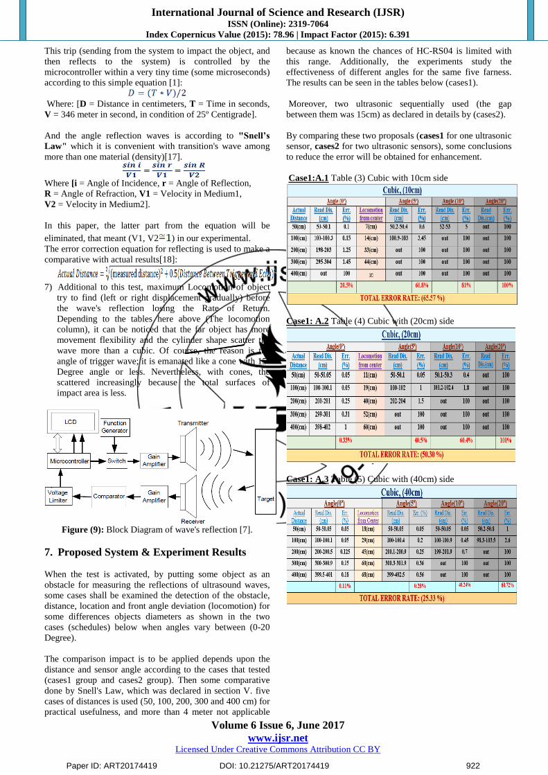
This trip (sending from the system to impact the object, and
then reflects to the system) is controlled by the
microcontroller within a very tiny time (some microseconds)
according to this simple equation [1]:
Where: [D = Distance in centimeters, T = Time in seconds,
V = 346 meter in second, in condition of 25º Centigrade].
And the angle reflection waves is according to "Snell’s
Law" which it is convenient with transition's wave among
more than one material (density)[17].
Where [i = Angle of Incidence, r = Angle of Reflection,
R = Angle of Refraction, V1 = Velocity in Medium1,
V2 = Velocity in Medium2].
In this paper, the latter part from the equation will be
eliminated, that meant (V1, V2 ) in our experimental. The error correction equation for reflecting is used to make a
comparative with actual results[18]:
7) Additional to this test, maximum Locomotion of object
try to find (left or right displacement gradually) before
the wave's reflection losing the Rate of Return.
Depending to the tables here above (The locomotion
column), it can be noticed that the far object has more
movement flexibility and the cylinder shape scatter the
wave more than a cubic. Of course, the reason is the
angle of trigger wave; it is emanated like a cone with 15-
Degree angle or less. Nevertheless, with cones, the
scattered increasingly because the total surfaces of
impact area is less.
Figure (9): Block Diagram of wave's reflection [7].
7. Proposed System & Experiment Results
When the test is activated, by putting some object as an
obstacle for measuring the reflections of ultrasound waves,
some cases shall be examined the detection of the obstacle,
distance, location and front angle deviation (locomotion) for
some differences objects diameters as shown in the two
cases (schedules) below when angles vary between (0-20
Degree).
The comparison impact is to be applied depends upon the
distance and sensor angle according to the cases that tested
(cases1 group and cases2 group). Then some comparative
done by Snell's Law, which was declared in section V. five
cases of distances is used (50, 100, 200, 300 and 400 cm) for
practical usefulness, and more than 4 meter not applicable
because as known the chances of HC-RS04 is limited with
this range. Additionally, the experiments study the
effectiveness of different angles for the same five farness.
The results can be seen in the tables below (cases1).
Moreover, two ultrasonic sequentially used (the gap
between them was 15cm) as declared in details by (cases2).
By comparing these two proposals (cases1 for one ultrasonic
sensor, cases2 for two ultrasonic sensors), some conclusions
to reduce the error will be obtained for enhancement.
Case1:A.1 Table (3) Cubic with 10cm side
Case1: A.2 Table (4) Cubic with (20cm) side
Case1: A.3 Table (5) Cubic with (40cm) side
Paper ID: ART20174419 DOI: 10.21275/ART20174419 922

International Journal of Science and Research (IJSR) ISSN (Online): 2319-7064
Index Copernicus Value (2015): 78.96 | Impact Factor (2015): 6.391
Volume 6 Issue 6, June 2017
www.ijsr.net Licensed Under Creative Commons Attribution CC BY
Case1: B.1 Table (6) Cylinder with (10cm) Diameter
Case1: B.2 Table (7) Cylinder with (20cm) Diameter
Case1: B.3 Table (8) Cylinder with (40cm) Diameter
With the cases of cones (Case C: 1, 2 and 3), three model
used (10cm base, 10cm height), (20cm base, 20cm height)
and (40cm base, 40cm height). The result was analogous
(out of range, error rate = 100%) for all cases, because the
reflections waves scattered immediately to the several
directions, except one cases (when two ultrasonic sensors
sequentially used by actual distance (50cm) with (40cm)
base and (40cm) height. as case (C.1) shown in table (9).
Case 1: C.1 Table (9) Cone (40cm) base, (40cm) height by
2 UsS
When two ultrasonic sensors sequentially used with
remnants shapes (Cubic and Cylinder), the error rate
noticeable reduced, some of cases the error rate considered
as negligible (approximate to zero) as shown in tables
(cases2) below:
Case2: A.1 Table (10) Cubic with 10cm side by 2 UsS
Case2: A.2 Table (11) Cubic with 20cm side by two UsS
Case2: A.3 Table (12) Cubic with 40cm side by two UsS
Case2: B.1 Table (13) Cylinder with (10cm) Diameter by 2
UsS
Case 2: B.2 Table (14) Cylinder with (20cm) Diameter by 2 UsS
Paper ID: ART20174419 DOI: 10.21275/ART20174419 923

International Journal of Science and Research (IJSR) ISSN (Online): 2319-7064
Index Copernicus Value (2015): 78.96 | Impact Factor (2015): 6.391
Volume 6 Issue 6, June 2017
www.ijsr.net Licensed Under Creative Commons Attribution CC BY
Case 2: B.3 Table (15) Cylinder with (40cm) Diameter by 2
UsS
For examples about these tests, it could see some result how
it's computed and obtained the parameters before estimating
the total average of errors for each distance, angle and
locomotion through serial monitor of Arduino interface.
Figure (10): Test distance for case1: A.1 and case2: A1
Figure (11): Test distance for case1: B.1
Figure (12): Test distance for case2: B.3
Figure (13): Test locomotion for case1: B.1
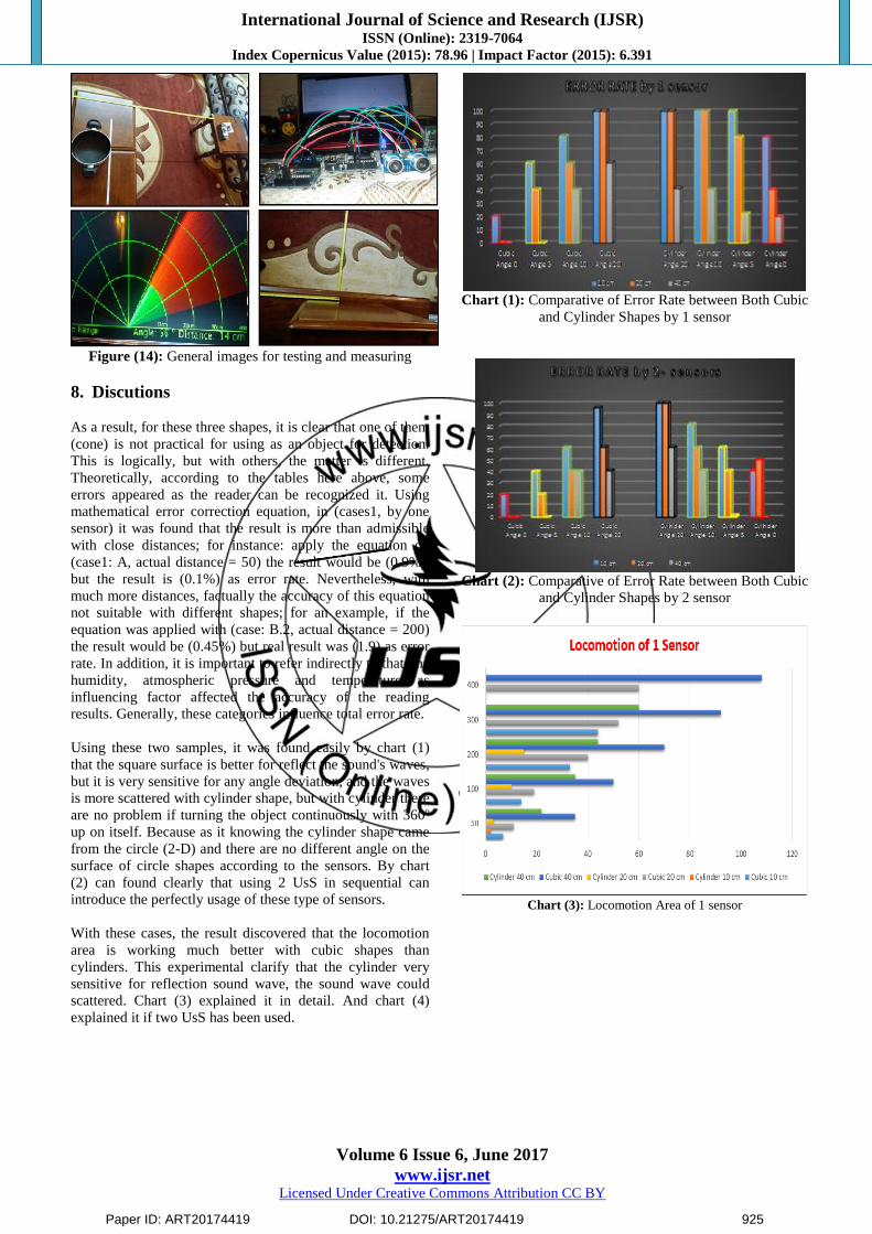
Finally, some image attached to clarify and give some
details about the real test how it is done.
Paper ID: ART20174419 DOI: 10.21275/ART20174419 924
International Journal of Science and Research (IJSR) ISSN (Online): 2319-7064
Index Copernicus Value (2015): 78.96 | Impact Factor (2015): 6.391
Volume 6 Issue 6, June 2017
www.ijsr.net Licensed Under Creative Commons Attribution CC BY
Figure (14): General images for testing and measuring
8. Discutions
As a result, for these three shapes, it is clear that one of them
(cone) is not practical for using as an object for detection.
This is logically, but with others, the matter is different.
Theoretically, according to the tables here above, some
errors appeared as the reader can be recognized it. Using
mathematical error correction equation, in (cases1, by one
sensor) it was found that the result is more than admissible
with close distances; for instance: apply the equation on
(case1: A, actual distance = 50) the result would be (0.9%),
but the result is (0.1%) as error rate. Nevertheless, with
much more distances, factually the accuracy of this equation
not suitable with different shapes; for an example, if the
equation was applied with (case: B.2, actual distance = 200)
the result would be (0.45%) but real result was (1.9) as error
rate. In addition, it is important to refer indirectly to that, the
humidity, atmospheric pressure and temperature as
influencing factor affected the accuracy of the reading
results. Generally, these categories influence total error rate.
Using these two samples, it was found easily by chart (1)
that the square surface is better for reflect the sound's waves,
but it is very sensitive for any angle deviation, and the waves
is more scattered with cylinder shape, but with cylinder there
are no problem if turning the object continuously with 360º
up on itself. Because as it knowing the cylinder shape came
from the circle (2-D) and there are no different angle on the
surface of circle shapes according to the sensors. By chart
(2) can found clearly that using 2 UsS in sequential can
introduce the perfectly usage of these type of sensors.
With these cases, the result discovered that the locomotion
area is working much better with cubic shapes than
cylinders. This experimental clarify that the cylinder very
sensitive for reflection sound wave, the sound wave could
scattered. Chart (3) explained it in detail. And chart (4)
explained it if two UsS has been used.
Chart (1): Comparative of Error Rate between Both Cubic
and Cylinder Shapes by 1 sensor
Chart (2): Comparative of Error Rate between Both Cubic
and Cylinder Shapes by 2 sensor
Chart (3): Locomotion Area of 1 sensor
Paper ID: ART20174419 DOI: 10.21275/ART20174419 925
International Journal of Science and Research (IJSR) ISSN (Online): 2319-7064
Index Copernicus Value (2015): 78.96 | Impact Factor (2015): 6.391
Volume 6 Issue 6, June 2017
www.ijsr.net Licensed Under Creative Commons Attribution CC BY
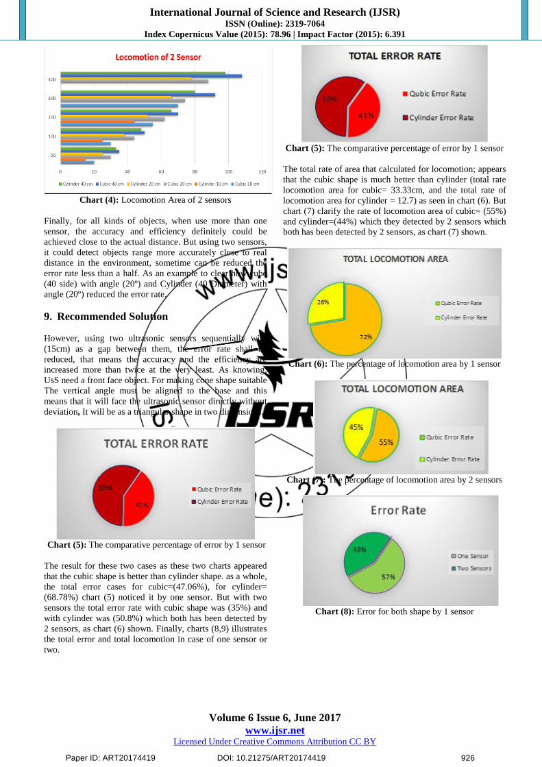
Chart (4): Locomotion Area of 2 sensors
Finally, for all kinds of objects, when use more than one
sensor, the accuracy and efficiency definitely could be
achieved close to the actual distance. But using two sensors,
it could detect objects range more accurately close to real
distance in the environment, sometime can be reduced the
error rate less than a half. As an example to clear how cube
(40 side) with angle (20º) and Cylinder (40 Diameter) with
angle (20º) reduced the error rate.
9. Recommended Solution
However, using two ultrasonic sensors sequentially with
(15cm) as a gap between them, the error rate shall be
reduced, that means the accuracy and the efficiency are
increased more than twice at the very least. As knowing,
UsS need a front face object. For making cone shape suitable
The vertical angle must be aligned to the base and this
means that it will face the ultrasonic sensor directly without
deviation, It will be as a triangular shape in two dimensions.
Chart (5): The comparative percentage of error by 1 sensor
The result for these two cases as these two charts appeared
that the cubic shape is better than cylinder shape. as a whole,
the total error cases for cubic=(47.06%), for cylinder=
(68.78%) chart (5) noticed it by one sensor. But with two
sensors the total error rate with cubic shape was (35%) and
with cylinder was (50.8%) which both has been detected by
2 sensors, as chart (6) shown. Finally, charts (8,9) illustrates
the total error and total locomotion in case of one sensor or
two.
Chart (5): The comparative percentage of error by 1 sensor
The total rate of area that calculated for locomotion; appears
that the cubic shape is much better than cylinder (total rate
locomotion area for cubic= 33.33cm, and the total rate of
locomotion area for cylinder = 12.7) as seen in chart (6). But
chart (7) clarify the rate of locomotion area of cubic= (55%)
and cylinder=(44%) which they detected by 2 sensors which
both has been detected by 2 sensors, as chart (7) shown.
Chart (6): The percentage of locomotion area by 1 sensor
Chart (7): The percentage of locomotion area by 2 sensors
Chart (8): Error for both shape by 1 sensor
Paper ID: ART20174419 DOI: 10.21275/ART20174419 926

International Journal of Science and Research (IJSR) ISSN (Online): 2319-7064
Index Copernicus Value (2015): 78.96 | Impact Factor (2015): 6.391
Volume 6 Issue 6, June 2017
www.ijsr.net Licensed Under Creative Commons Attribution CC BY
Chart (9): Error for both shape by 1 sensor
In some cases, cubic has better to be used as an obstacle with
these sensors, but should have an angle near to (0) degree in
front face of the trigger. It is important to point out that the
concavity and the convexity are considered as impact factors
that affect the result. Otherwise, cylinder shape is more
suitable even if it has mobility as self-turning case. Despite
that as figure (14), (15) clarifies that bigger diameter in
cylinder shape is needed as adequate surface in comparison
with square shape. The proposal found that the cube with
(11 cm) side has the same reflection wave as a (40cm)
diameter of cylinder. Nevertheless, as showing that the
cylinder with 40cm diameter is failed when located at
(400cm) in front face of ultrasonic sensors, by calculating
the rate by Auto CAD program, just found that it need for a
(120cm) diameter of cylinder for equaling to 16cm of cubic
side. It should mention that there are a weak reflection area
belong to the cylinder can give some useful reflection with
less accuracy.
Figure (14): Tangent of 40cm diameter of Cylinder
Figure (15): Tangent of 120cm diameter of Cylinder
10. Conciliation
The approach that presented in the paper is outfit and the
performance was interesting for measuring the obstacle
distance with sensitivity for three shapes and multistage of
angles. HC-SR04 and Arduino Microprocessor were
satisfied for these cases as a result are admissible with
different shapes and locations. The trigonometry as an
algorithm was successfully getting minimal errors, each
obstacle detection is a very good to be used in variety kinds
of applications, cubes and cylinder depending on the demand
of use. It be clear that the biggest size is more precisely for
detecting objects and have more flexibility of movements.
The angles is very sensitive for reflecting the sound waves,
the echo pin work better with face-to-face objects. By using
two ultrasonic sensors, the qualification of detection be more
impact.
References
[1] Vidhya, D.S., et al., Obstacle Detection using
Ultrasonic Sensors. APR 2016. 2(11): p. 316.
[2] Marioli, D., et al., Digital time-of-flight measurement
for ultrasonic sensors. IEEE Transactions on
Instrumentation and Measurement, 1992. 41(1): p. 93-
97.
[3] Ohtani, K. and M. Baba, Shape Recognition and
Position Measurement of an Object Using an Ultrasonic
Sensor Array. 2012: INTECH Open Access Publisher.
[4] Herman, A.M. and C.N. Jeffress, Occupational Safety
and Health Administration. 2017.
[5] He, H. and J. Liu. The design of ultrasonic distance
measurement system based on S3C2410. in Intelligent
Computation Technology and Automation (ICICTA),
2008 International Conference on. 2008. Proceedings of
the IEEE International Conference on Intelligent
Computation Technology and Automation,Oct. 2008,
pp. 44-47. : IEEE.
[6] Jang, Y., et al. A preliminary study for portable walking
distance measurement system using ultrasonic sensors.
in 2007 29th Annual International Conference of the
IEEE Engineering in Medicine and Biology Society.
2007. Proceedings of the 29th Annual IEEE
International Conference of the EMBS, France, Aug.
2007, pp. 5290-5293: IEEE.
[7] Chang, C.C., C.Y. Chang, and Y.T. Cheng. Distance
measurement technology development at remotely
teleoperated robotic manipulator system for underwater
constructions. in Underwater Technology, 2004. UT'04.
2004 International Symposium on. 2004: IEEE.
[8] Wu, T.Y., et al., Theory and fundamentals of
ultrasound, in Advances in ultrasound technology for
environmental remediation. 2011, Springer. p. 5-12.
[9] Kelman, M., Distance Measurement via Using of
Ultrasonic Sensor. Journal of Automation and Control,
2015. 3(3): p. 71-74.
[10] Golhar, Y. and U. Shrawankar, Human Gesture
Detection & Recognition: A Need of an Era. 2016.
[11] Qi, Y., et al., Assessment of foot trajectory for human
gait phase detection using wireless ultrasonic sensor
network. IEEE Transactions on Neural Systems and
Rehabilitation Engineering, 2016. 24(1): p. 88-97.
[12] Lucio, F.A., Auto Smart Obstacle Detection. IJSTE,
2016. 2(09): p. 014.
[13] Hu, L., et al., Laser Frequency Noise Cancelation in a
Phase-Shifted Fiber Bragg Grating Ultrasonic Sensor
System Using a Reference Grating Channel. IEEE
Photonics Journal, 2016. 8(1): p. 1-8.
Paper ID: ART20174419 DOI: 10.21275/ART20174419 927

International Journal of Science and Research (IJSR) ISSN (Online): 2319-7064
Index Copernicus Value (2015): 78.96 | Impact Factor (2015): 6.391
Volume 6 Issue 6, June 2017
www.ijsr.net Licensed Under Creative Commons Attribution CC BY
[14] Guenther, T. and A. Kroll. Automated detection of
compressed air leaks using a scanning ultrasonic sensor
system. in Sensors Applications Symposium (SAS), 2016
IEEE: IEEE.
[15] Choe, S., et al., Evaluation of sensing technology for the
prevention of backover accidents in construction work
zones. Journal of information technology in
construction, 2014. 19: p. 1-19.
[16] D’Ausilio, A., Arduino: A low-cost multipurpose
lab equipment. Behavior research methods, 2011. 44(2):
p. 305-313.
[17] Cruz-Silva, O.H., O.A. Jaramillo, and M.n. Borunda,
Full analytical formulation for Dielectric Totally
Internally Reflecting Concentrators designs and solar
applications. Renewable Energy, 2017. 101: p. 804-815.
[18] Baikov, D.V., et al. Simulation of a group of
rangefinders adapted to alterations of measurement
angle. in AIP Conference Proceedings. 2016: AIP
Publishing.
Paper ID: ART20174419 DOI: 10.21275/ART20174419 928
Related Documents