OBJECTIVES
Mar 13, 2016
OBJECTIVES. After studying Chapter 7, the reader should be able to: Explain how an automatic transmission hydraulic system operates. List the valves used in an automatic transmission. Describe the operation of the valves in an automatic transmission. - PowerPoint PPT Presentation
Welcome message from author
This document is posted to help you gain knowledge. Please leave a comment to let me know what you think about it! Share it to your friends and learn new things together.
Transcript

Automatic Transmissions and Transaxles, Fourth EditionBy Tom Birch and Chuck Rockwood
© 2010 Pearson Higher Education, Inc.Pearson Prentice Hall - Upper Saddle River, NJ 07458
OBJECTIVES
After studying Chapter 7, the reader should be able to:1. Explain how an automatic transmission hydraulic
system operates.2. List the valves used in an automatic transmission.3. Describe the operation of the valves in an
automatic transmission.4. Describe how vehicle speed and load affect
automatic shifts.5. Follow an upshift or downshift sequence through a
hydraulic schematic.

Automatic Transmissions and Transaxles, Fourth EditionBy Tom Birch and Chuck Rockwood
© 2010 Pearson Higher Education, Inc.Pearson Prentice Hall - Upper Saddle River, NJ 07458
INTRODUCTION
• The hydraulic system enables an automatic transmission to operate automatically.
• The basic function of the hydraulic control system is to:– Schedule shifts to optimize engine performance,– Provide the best gear ratio for the driving conditions,– Safely shift into reverse when requested– Provide driver control of the operating ranges,– Provide engine braking to help control vehicle speed on
downgrades,– Lock or unlock the torque converter clutch.

Automatic Transmissions and Transaxles, Fourth EditionBy Tom Birch and Chuck Rockwood
© 2010 Pearson Higher Education, Inc.Pearson Prentice Hall - Upper Saddle River, NJ 07458
INTRODUCTION
FIGURE 7-1 This electronic transmission valve body (a) has only five valves. Four solenoids in the solenoid assembly (b) control shifts and torque converter clutch (TCC) apply and release. (Courtesy of Chrysler Corporation)

Automatic Transmissions and Transaxles, Fourth EditionBy Tom Birch and Chuck Rockwood
© 2010 Pearson Higher Education, Inc.Pearson Prentice Hall - Upper Saddle River, NJ 07458
INTRODUCTION
FIGURE 7-1 (CONTINUED) This electronic transmission valve body (a) has only five valves. Four solenoids in the solenoid assembly (b) control shifts and torque converter clutch (TCC) apply and release. (Courtesy of Chrysler Corporation)
Automatic Transmissions and Transaxles, Fourth EditionBy Tom Birch and Chuck Rockwood
© 2010 Pearson Higher Education, Inc.Pearson Prentice Hall - Upper Saddle River, NJ 07458
INTRODUCTION
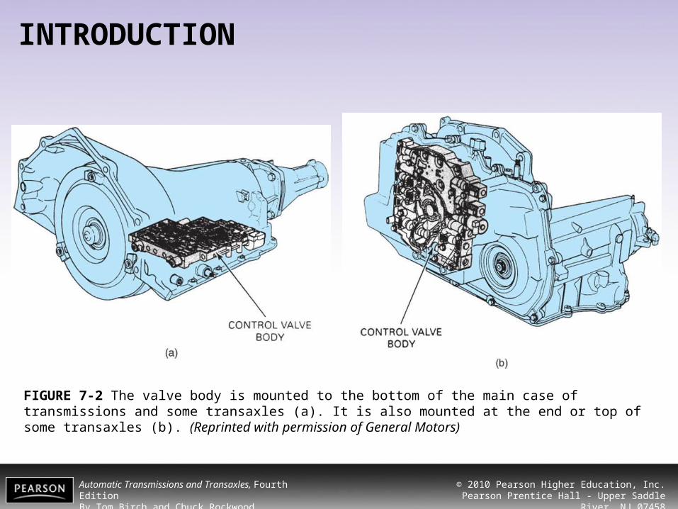
FIGURE 7-2 The valve body is mounted to the bottom of the main case of transmissions and some transaxles (a). It is also mounted at the end or top of some transaxles (b). (Reprinted with permission of General Motors)

Automatic Transmissions and Transaxles, Fourth EditionBy Tom Birch and Chuck Rockwood
© 2010 Pearson Higher Education, Inc.Pearson Prentice Hall - Upper Saddle River, NJ 07458
INTRODUCTION
FIGURE 7-3 The switch valve (a) will shift the fluid flow from circuit 1 to circuit 2 when the controlling pressure increases. This regulator valve has two servo valves (TV boost, and D2 and rev. boost) (b), which cause a pressure increase when the throttle is opened or when the transmission is shifted into D2 or reverse. This regulator valve (c) controls supply pressure to become mainline pressure.

Automatic Transmissions and Transaxles, Fourth EditionBy Tom Birch and Chuck Rockwood
© 2010 Pearson Higher Education, Inc.Pearson Prentice Hall - Upper Saddle River, NJ 07458
INTRODUCTION
TABLE 7-1 Hydraulic System Subcircuits

Automatic Transmissions and Transaxles, Fourth EditionBy Tom Birch and Chuck Rockwood
© 2010 Pearson Higher Education, Inc.Pearson Prentice Hall - Upper Saddle River, NJ 07458
PRESSURE DEVELOPMENT AND CONTROL
• As soon as the engine starts, the torque converter hub drives the transmission pump to produce fluid flow.
• Pressure is created by resistance to fluid flow. • This pressure is called:
– Line– Mainline– Supply– Control pressure

Automatic Transmissions and Transaxles, Fourth EditionBy Tom Birch and Chuck Rockwood
© 2010 Pearson Higher Education, Inc.Pearson Prentice Hall - Upper Saddle River, NJ 07458
PRESSURE DEVELOPMENT AND CONTROL
FIGURE 7-4 Many pressure regulator valves have three positions. (a) The spring has moved the valve to the bottom of the bore. (b) Line pressure is moving the valve upward, opening the passage to the torque converter (circle). (c) Increased line pressure has moved the valve upward to where it can release pressure to the pump inlet (circle). Note that boost pressure in either of the two upper ports can cause a pressure increase.

Automatic Transmissions and Transaxles, Fourth EditionBy Tom Birch and Chuck Rockwood
© 2010 Pearson Higher Education, Inc.Pearson Prentice Hall - Upper Saddle River, NJ 07458
PRESSURE DEVELOPMENT AND CONTROL
FIGURE 7-5 The pressure regulator of this variable displacement vane pump can send fluid pressure to the DECREASE passage. This pressure will move the pump slide to the right and reduce pump output. (Reprinted with permission of General Motors)

Automatic Transmissions and Transaxles, Fourth EditionBy Tom Birch and Chuck Rockwood
© 2010 Pearson Higher Education, Inc.Pearson Prentice Hall - Upper Saddle River, NJ 07458
PRESSURE DEVELOPMENT AND CONTROL
FIGURE 7-6 This manual valve is arranged so it dumps line pressure to the sump in park (circle). This reduces line pressure to below 30 psi. (Courtesy of Chrysler Corporation)
Automatic Transmissions and Transaxles, Fourth EditionBy Tom Birch and Chuck Rockwood
© 2010 Pearson Higher Education, Inc.Pearson Prentice Hall - Upper Saddle River, NJ 07458
PRESSURE DEVELOPMENT AND CONTROL
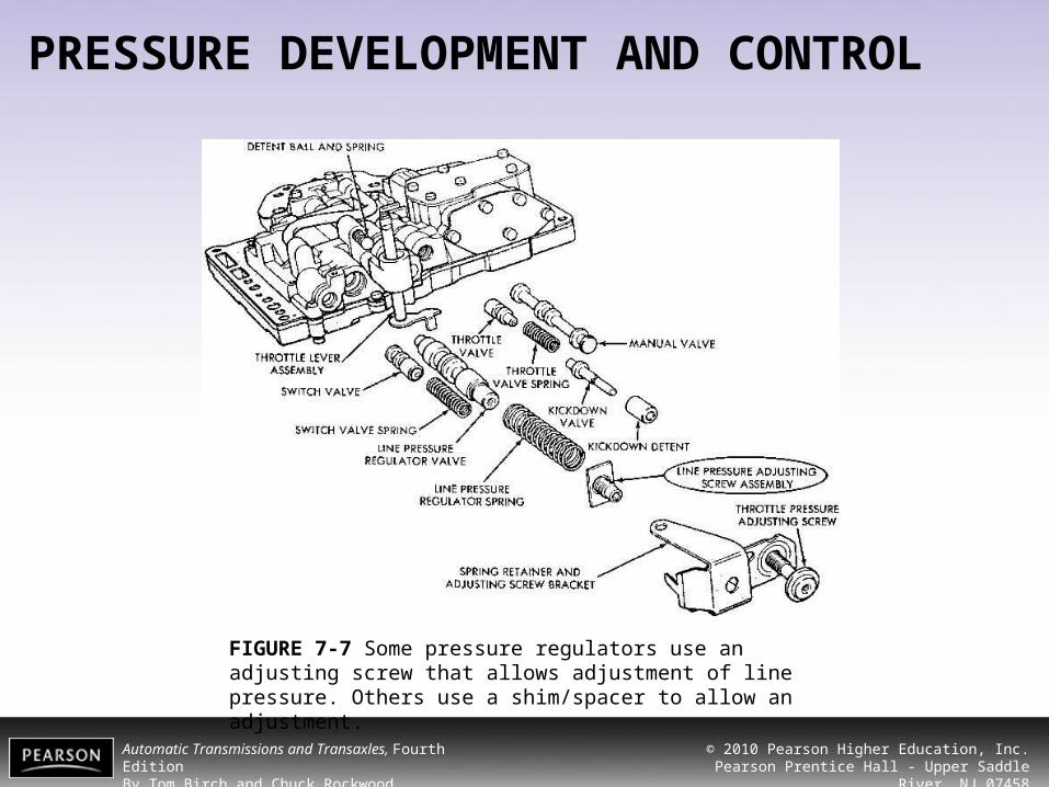
FIGURE 7-7 Some pressure regulators use an adjusting screw that allows adjustment of line pressure. Others use a shim/spacer to allow an adjustment.

Automatic Transmissions and Transaxles, Fourth EditionBy Tom Birch and Chuck Rockwood
© 2010 Pearson Higher Education, Inc.Pearson Prentice Hall - Upper Saddle River, NJ 07458
PRESSURE DEVELOPMENT AND CONTROL
FIGURE 7-8 Hydraulic pressure moves this regulator valve to the left against spring tension. Pressure in the manual valve circuit will work against hydraulic pressure to increase/boost line pressure. Pressure in the overdrive clutch circuit will reduce/cut back line pressure. (Courtesy of Chrysler Corporation)

Automatic Transmissions and Transaxles, Fourth EditionBy Tom Birch and Chuck Rockwood
© 2010 Pearson Higher Education, Inc.Pearson Prentice Hall - Upper Saddle River, NJ 07458
PRESSURE DEVELOPMENT AND CONTROL
FIGURE 7-9 Fluid from the manual valve reverse circuit acts on the primary regulator valve to increase line pressure in reverse. (Courtesy of Toyota Motor Sales USA, Inc.)

Automatic Transmissions and Transaxles, Fourth EditionBy Tom Birch and Chuck Rockwood
© 2010 Pearson Higher Education, Inc.Pearson Prentice Hall - Upper Saddle River, NJ 07458
TORQUE CONVERTER, OIL COOLER, AND LUBRICATION CIRCUIT• As soon as the supply circuit begins to develop
pressure, the regulator valve moves slightly and opens a passage to the torque converter.
• This fluid flow serves several purposes:– It ensures that the torque converter is filled so it can
transmit torque from the engine to the transmission’s input shaft.
– It helps control converter fluid temperature.– It provides lubrication for the moving parts inside the
transmission

Automatic Transmissions and Transaxles, Fourth EditionBy Tom Birch and Chuck Rockwood
© 2010 Pearson Higher Education, Inc.Pearson Prentice Hall - Upper Saddle River, NJ 07458
TORQUE CONVERTER, OIL COOLER, AND LUBRICATION CIRCUIT
FIGURE 7-10 The converter and cooler feed circuit begins at the pressure regulator, goes through the converter and cooler, and then into the lube passages. Note that the cooler and the lines connecting it to the transmission are outside of the transmission. (Courtesy of Chrysler Corporation)

Automatic Transmissions and Transaxles, Fourth EditionBy Tom Birch and Chuck Rockwood
© 2010 Pearson Higher Education, Inc.Pearson Prentice Hall - Upper Saddle River, NJ 07458
TORQUE CONVERTER, OIL COOLER, AND LUBRICATION CIRCUIT• Torque Converter Pressure Control• Torque Converter Clutch Control• Cooler Flow• Lubrication Flow

Automatic Transmissions and Transaxles, Fourth EditionBy Tom Birch and Chuck Rockwood
© 2010 Pearson Higher Education, Inc.Pearson Prentice Hall - Upper Saddle River, NJ 07458
TORQUE CONVERTER, OIL COOLER, AND LUBRICATION CIRCUIT
FIGURE 7-11 When the engine is not running, the regulator valve spring moves the T/C control valve to the right, blocking the cooler passage and reducing the chance of converter drain down. Note the bypass valve that will open if the cooler becomes plugged. (Courtesy of Chrysler Corporation)

Automatic Transmissions and Transaxles, Fourth EditionBy Tom Birch and Chuck Rockwood
© 2010 Pearson Higher Education, Inc.Pearson Prentice Hall - Upper Saddle River, NJ 07458
TORQUE CONVERTER, OIL COOLER, AND LUBRICATION CIRCUIT
FIGURE 7-12 With the torque converter clutch (TCC) released, fluid enters this converter through the input shaft. It leaves through the area between the input shaft and the stator support. (Courtesy of Chrysler Corporation)

Automatic Transmissions and Transaxles, Fourth EditionBy Tom Birch and Chuck Rockwood
© 2010 Pearson Higher Education, Inc.Pearson Prentice Hall - Upper Saddle River, NJ 07458
TORQUE CONVERTER, OIL COOLER, AND LUBRICATION CIRCUIT
FIGURE 7-13 This TCC is controlled by a valve that is controlled by a solenoid that is controlled by the power train control module (PCM). When the solenoid is energized (right), the valve moves to the left, and this applies the TCC.

Automatic Transmissions and Transaxles, Fourth EditionBy Tom Birch and Chuck Rockwood
© 2010 Pearson Higher Education, Inc.Pearson Prentice Hall - Upper Saddle River, NJ 07458
TORQUE CONVERTER, OIL COOLER, AND LUBRICATION CIRCUIT
FIGURE 7-14 The lock-up valve and fail-safe valve control the switch valve. This in turn controls fluid flow through the converter and therefore converter lock-up. (Courtesy of Chrysler Corporation)

Automatic Transmissions and Transaxles, Fourth EditionBy Tom Birch and Chuck Rockwood
© 2010 Pearson Higher Education, Inc.Pearson Prentice Hall - Upper Saddle River, NJ 07458
TORQUE CONVERTER, OIL COOLER, AND LUBRICATION CIRCUIT
FIGURE 7-15 The transmission cooler is normally mounted in the colder, outlet tank of the radiator. Steel lines are normally used to connect the transmission to the cooler. (Courtesy of Chrysler Corporation)

Automatic Transmissions and Transaxles, Fourth EditionBy Tom Birch and Chuck Rockwood
© 2010 Pearson Higher Education, Inc.Pearson Prentice Hall - Upper Saddle River, NJ 07458
TORQUE CONVERTER, OIL COOLER, AND LUBRICATION CIRCUIT
FIGURE 7-16 This cooler has a large, flat passage from its inlet to its outlet (a). The screenlike turbulator is shown (b).

Automatic Transmissions and Transaxles, Fourth EditionBy Tom Birch and Chuck Rockwood
© 2010 Pearson Higher Education, Inc.Pearson Prentice Hall - Upper Saddle River, NJ 07458
TORQUE CONVERTER, OIL COOLER, AND LUBRICATION CIRCUIT
FIGURE 7-17 Cold fluid tends to stick to the walls of a plain tube cooler (top). The turbulator causes fluid turbulence to promote mixing so all of the fluid cools (bottom).

Automatic Transmissions and Transaxles, Fourth EditionBy Tom Birch and Chuck Rockwood
© 2010 Pearson Higher Education, Inc.Pearson Prentice Hall - Upper Saddle River, NJ 07458
TORQUE CONVERTER, OIL COOLER, AND LUBRICATION CIRCUIT
FIGURE 7-18 An auxiliary filter can be installed in one of the cooler lines to help trap contaminants (a). The cutaway view shows the internal magnet and folded paper filter element (b). (Courtesy of SPX Filtran)

Automatic Transmissions and Transaxles, Fourth EditionBy Tom Birch and Chuck Rockwood
© 2010 Pearson Higher Education, Inc.Pearson Prentice Hall - Upper Saddle River, NJ 07458
TORQUE CONVERTER, OIL COOLER, AND LUBRICATION CIRCUIT
FIGURE 7-19 An auxiliary cooler is mounted so the fluid flows through it and then through the standard cooler in the radiator. (Courtesy of Chrysler Corporation)

Automatic Transmissions and Transaxles, Fourth EditionBy Tom Birch and Chuck Rockwood
© 2010 Pearson Higher Education, Inc.Pearson Prentice Hall - Upper Saddle River, NJ 07458
TORQUE CONVERTER, OIL COOLER, AND LUBRICATION CIRCUIT
FIGURE 7-20 Transmission lube passages. Note how the passage leads to gears and bushings. (Courtesy of Toyota Motor Sales USA, Inc.)

Automatic Transmissions and Transaxles, Fourth EditionBy Tom Birch and Chuck Rockwood
© 2010 Pearson Higher Education, Inc.Pearson Prentice Hall - Upper Saddle River, NJ 07458
TORQUE CONVERTER, OIL COOLER, AND LUBRICATION CIRCUIT
FIGURE 7-21 This planet carrier burned out from lack of lubrication; note the excess clearance and dark coloration at the planet gear shafts.

Automatic Transmissions and Transaxles, Fourth EditionBy Tom Birch and Chuck Rockwood
© 2010 Pearson Higher Education, Inc.Pearson Prentice Hall - Upper Saddle River, NJ 07458
THROTTLE PRESSURE
• A circuit carrying a throttle pressure signal is always available while the engine is running in most transmissions.
• Throttle valves are pressure-regulating valves, and they provide a pressure signal that is proportionate to the load on the engine

Automatic Transmissions and Transaxles, Fourth EditionBy Tom Birch and Chuck Rockwood
© 2010 Pearson Higher Education, Inc.Pearson Prentice Hall - Upper Saddle River, NJ 07458
THROTTLE PRESSURE
FIGURE 7-22 The throttle valve produces a pressure signal that is directly related to throttle opening or engine load. This pressure signal is used to control line pressure so that line pressure increases as the throttle is opened.

Automatic Transmissions and Transaxles, Fourth EditionBy Tom Birch and Chuck Rockwood
© 2010 Pearson Higher Education, Inc.Pearson Prentice Hall - Upper Saddle River, NJ 07458
THROTTLE PRESSURE
FIGURE 7-23 In this hydraulically controlled transmission, the shift valves are positioned by a spring and hydraulic pressures from the throttle valve and governor. (Courtesy of Chrysler Corporation)

Automatic Transmissions and Transaxles, Fourth EditionBy Tom Birch and Chuck Rockwood
© 2010 Pearson Higher Education, Inc.Pearson Prentice Hall - Upper Saddle River, NJ 07458
THROTTLE PRESSURE
• The transmission control system uses throttle pressure to reprogram or reschedule several areas of operation:– Shift quality– Shift timing– Shift feel– Torque converter clutch
control
FIGURE 7-24 Application speed of this front band is controlled by the accumulator stroke rate, and this is
controlled by the shuttle valve and the 1–2 shift control valve. (Courtesy of Chrysler Corporation)

Automatic Transmissions and Transaxles, Fourth EditionBy Tom Birch and Chuck Rockwood
© 2010 Pearson Higher Education, Inc.Pearson Prentice Hall - Upper Saddle River, NJ 07458
THROTTLE PRESSURE
FIGURE 7-25 This mechanical throttle valve is operated by a cable that is connected to the engine throttle body and accelerator pedal. (Courtesy of Chrysler Corporation)

Automatic Transmissions and Transaxles, Fourth EditionBy Tom Birch and Chuck Rockwood
© 2010 Pearson Higher Education, Inc.Pearson Prentice Hall - Upper Saddle River, NJ 07458
THROTTLE PRESSURE
• Mechanical Throttle Valves
• Vacuum Throttle Valves• Wide-Open Throttle
Kickdown Valve
FIGURE 7-26 At wide-open throttle, the kickdown valve pushes the throttle valve to the end of the bore. At this position, TV pressure is equal to line pressure in both the TV and kickdown passages. (Courtesy of Chrysler Corporation)

Automatic Transmissions and Transaxles, Fourth EditionBy Tom Birch and Chuck Rockwood
© 2010 Pearson Higher Education, Inc.Pearson Prentice Hall - Upper Saddle River, NJ 07458
THROTTLE PRESSURE
FIGURE 7-27 With high manifold vacuum, the modulator diaphragm and modulator valve are to the left, and modulator pressure is low. When manifold vacuum drops, the spring moves the diaphragm toward the right, and modulator pressure will increase. Note the bellows used in this modulator. (Reprinted with permission of General Motors)

Automatic Transmissions and Transaxles, Fourth EditionBy Tom Birch and Chuck Rockwood
© 2010 Pearson Higher Education, Inc.Pearson Prentice Hall - Upper Saddle River, NJ 07458
THROTTLE PRESSURE
FIGURE 7-28 Vacuum modulators have different diameters, which change the relative strength of the modulator.

Automatic Transmissions and Transaxles, Fourth EditionBy Tom Birch and Chuck Rockwood
© 2010 Pearson Higher Education, Inc.Pearson Prentice Hall - Upper Saddle River, NJ 07458
THROTTLE PRESSURE
FIGURE 7-29 Manifold vacuum varies with load. Cruising at light load produces about 15 to 20 in. Hg. A high load produces zero vacuum,0 in. Hg. (Courtesy of Nissan North America, Inc.)

Automatic Transmissions and Transaxles, Fourth EditionBy Tom Birch and Chuck Rockwood
© 2010 Pearson Higher Education, Inc.Pearson Prentice Hall - Upper Saddle River, NJ 07458
MANUAL VALUE
• The manual valve controls the fluid flow to the band servos, clutch apply pistons, and the shift valves for the various forward and reverse gears. – This valve is also called a selector valve.
FIGURE 7-30 The manual valve is moved by the shift lever and held in position by the detent lever (cam).

Automatic Transmissions and Transaxles, Fourth EditionBy Tom Birch and Chuck Rockwood
© 2010 Pearson Higher Education, Inc.Pearson Prentice Hall - Upper Saddle River, NJ 07458
MANUAL VALUE
FIGURE 7-31 The manual valve is in drive and the transmission is in first gear. Fluid is being sent to the rear clutch, accumulator, 1–2 shift valve, throttle valve, and governor. (Courtesy of Chrysler Corporation)

Automatic Transmissions and Transaxles, Fourth EditionBy Tom Birch and Chuck Rockwood
© 2010 Pearson Higher Education, Inc.Pearson Prentice Hall - Upper Saddle River, NJ 07458
GOVERNOR VALVE
• The transmission will begin transferring power and rotating the output shaft when the selector lever is moved to drive, intermediate, or low.
• When the output shaft starts turning, the governor spins with it.
• The governor is either shaft mounted (attached directly onto the output shaft) or case mounted (driven by a gear on the output shaft).

Automatic Transmissions and Transaxles, Fourth EditionBy Tom Birch and Chuck Rockwood
© 2010 Pearson Higher Education, Inc.Pearson Prentice Hall - Upper Saddle River, NJ 07458
GOVERNOR VALVE
FIGURE 7-32 A case-mounted governor is driven by a gear on the output shaft. It provides a pressure signal relative to vehicle speed. (Reprinted with permission of General Motors)

Automatic Transmissions and Transaxles, Fourth EditionBy Tom Birch and Chuck Rockwood
© 2010 Pearson Higher Education, Inc.Pearson Prentice Hall - Upper Saddle River, NJ 07458
GOVERNOR VALVE
FIGURE 7-33 The ideal governor pressure signal increases in exact proportion to vehicle speed, but a simple governor produces a signal that is too low at intermediate speeds or too high at higher speeds. The pressure signal from a two-stage governor comes closer to matching vehicle speed.

Automatic Transmissions and Transaxles, Fourth EditionBy Tom Birch and Chuck Rockwood
© 2010 Pearson Higher Education, Inc.Pearson Prentice Hall - Upper Saddle River, NJ 07458
GOVERNOR VALVE
• Governor valve assemblies are manufactured in four basic styles.
• Two are shaft mounted, and two are case mounted:– Shaft mounted with the weight(s) opposing the valve– Shaft mounted with a primary and secondary valve– Case mounted with a pair of primary and secondary
weights – Case-mounted bleed-off system

Automatic Transmissions and Transaxles, Fourth EditionBy Tom Birch and Chuck Rockwood
© 2010 Pearson Higher Education, Inc.Pearson Prentice Hall - Upper Saddle River, NJ 07458
GOVERNOR VALVE
FIGURE 7-34 As the vehicle speeds up, centrifugal force acting on the governor weight tries to move the weight and valve toward the right to increase governor pressure. This is opposed by governor pressure at the valve, which tries to move the valve toward the left and reduce governor pressure. (Courtesy of Chrysler Corporation)

Automatic Transmissions and Transaxles, Fourth EditionBy Tom Birch and Chuck Rockwood
© 2010 Pearson Higher Education, Inc.Pearson Prentice Hall - Upper Saddle River, NJ 07458
GOVERNOR VALVE
FIGURE 7-35 This two-stage, shaft-mounted governor uses both a primary and secondary valve. (Courtesy of Chrysler Corporation)

Automatic Transmissions and Transaxles, Fourth EditionBy Tom Birch and Chuck Rockwood
© 2010 Pearson Higher Education, Inc.Pearson Prentice Hall - Upper Saddle River, NJ 07458
GOVERNOR VALVE
FIGURE 7-36 Centrifugal force will cause the two weights to move outward. This pushes the two balls against their seats, reducing the amount of exhaust and increasing governor pressure. (Reprinted with permission of General Motors)

Automatic Transmissions and Transaxles, Fourth EditionBy Tom Birch and Chuck Rockwood
© 2010 Pearson Higher Education, Inc.Pearson Prentice Hall - Upper Saddle River, NJ 07458
GOVERNOR VALVE
FIGURE 7-37 Centrifugal force produces an upward force on the valve that will increase governor pressure if the valve moves. Governor pressure at the top of the valve opposes this action. The governor valve is positioned between these two forces. (Reprinted with permission of General Motors)
Automatic Transmissions and Transaxles, Fourth EditionBy Tom Birch and Chuck Rockwood
© 2010 Pearson Higher Education, Inc.Pearson Prentice Hall - Upper Saddle River, NJ 07458
SHIFT VALVES
• An upshift or downshift occurs when the shift valves move.
• Shift valves are balanced between the governor pressure trying to move the valve to cause an upshift and the spring plus throttle pressure trying to resist an upshift.

Automatic Transmissions and Transaxles, Fourth EditionBy Tom Birch and Chuck Rockwood
© 2010 Pearson Higher Education, Inc.Pearson Prentice Hall - Upper Saddle River, NJ 07458
SHIFT VALVES
FIGURE 7-38 Governor pressure can move this 1–2 shift valve from the downshift position (left) to the upshift position.

Automatic Transmissions and Transaxles, Fourth EditionBy Tom Birch and Chuck Rockwood
© 2010 Pearson Higher Education, Inc.Pearson Prentice Hall - Upper Saddle River, NJ 07458
SHIFT VALVES
FIGURE 7-39 The 1–2 shift valve has moved to upshift, allowing drive oil to flow into the second-gear passages. Fluid pressure moves the front servo to apply the band and also strokes the accumulator piston. (Courtesy of Chrysler Corporation)

Automatic Transmissions and Transaxles, Fourth EditionBy Tom Birch and Chuck Rockwood
© 2010 Pearson Higher Education, Inc.Pearson Prentice Hall - Upper Saddle River, NJ 07458
SHIFT VALVES
FIGURE 7-40 The 2–3 shift valve has moved to upshift. Fluid pressure will apply the front clutch and also move the front servo to release the band. (Courtesy of Chrysler Corporation)

Automatic Transmissions and Transaxles, Fourth EditionBy Tom Birch and Chuck Rockwood
© 2010 Pearson Higher Education, Inc.Pearson Prentice Hall - Upper Saddle River, NJ 07458
SHIFT VALVES
FIGURE 7-41 Both parallel-feed shift valves are connected to drive oil (top); an upshift will occur when governor oil moves either one to the right. With series-feed shift valves, drive oil feeds only the 1–2 shift valve, and the 2–3 shift valve is fed from the 1–2 valve (bottom).

Automatic Transmissions and Transaxles, Fourth EditionBy Tom Birch and Chuck Rockwood
© 2010 Pearson Higher Education, Inc.Pearson Prentice Hall - Upper Saddle River, NJ 07458
SHIFT VALVES
• Shift Overlap• Shift Modifiers• Downshifts
– Coasting downshift– Part-throttle downshift– Detent downshift– Manual downshift

Automatic Transmissions and Transaxles, Fourth EditionBy Tom Birch and Chuck Rockwood
© 2010 Pearson Higher Education, Inc.Pearson Prentice Hall - Upper Saddle River, NJ 07458
SHIFT VALVES
FIGURE 7-42 Shift overlap is the time period as the band releases and the direct clutch applies between second and third gears.

Automatic Transmissions and Transaxles, Fourth EditionBy Tom Birch and Chuck Rockwood
© 2010 Pearson Higher Education, Inc.Pearson Prentice Hall - Upper Saddle River, NJ 07458
SHIFT VALVES
FIGURE 7-43 When a clutch is applied, fluid pressure keeps the exhaust check ball tightly seated (right). When the pressure is released, centrifugal force moves the check ball off its seat and allows a fluid flow out of the clutch (left).

Automatic Transmissions and Transaxles, Fourth EditionBy Tom Birch and Chuck Rockwood
© 2010 Pearson Higher Education, Inc.Pearson Prentice Hall - Upper Saddle River, NJ 07458
SHIFT VALVES
FIGURE 7-44 Centrifugal force in the balance/release cavity (a) generates the same fluid force as that in the apply chamber (b). This balanced force allows the springs to return the piston and release the clutch.

Automatic Transmissions and Transaxles, Fourth EditionBy Tom Birch and Chuck Rockwood
© 2010 Pearson Higher Education, Inc.Pearson Prentice Hall - Upper Saddle River, NJ 07458
SHIFT VALVES
TABLE 7-2 Shift Quality

Automatic Transmissions and Transaxles, Fourth EditionBy Tom Birch and Chuck Rockwood
© 2010 Pearson Higher Education, Inc.Pearson Prentice Hall - Upper Saddle River, NJ 07458
SHIFT VALVES
FIGURE 7-45 The pressure rise in this servo is delayed as the accumulator strokes.

Automatic Transmissions and Transaxles, Fourth EditionBy Tom Birch and Chuck Rockwood
© 2010 Pearson Higher Education, Inc.Pearson Prentice Hall - Upper Saddle River, NJ 07458
SHIFT VALVES
FIGURE 7-46 Clutch apply pressure seats the check ball so apply fluid must pass through the orifice (left). When the clutch releases, the check ball moves off it’s seat, allowing a faster clutch release because the fluid can bypass the orifice (right).

Automatic Transmissions and Transaxles, Fourth EditionBy Tom Birch and Chuck Rockwood
© 2010 Pearson Higher Education, Inc.Pearson Prentice Hall - Upper Saddle River, NJ 07458
SHIFT VALVES
FIGURE 7-47 The manual valve has been moved to manual-2 to send line pressure to the 2–3 shift valve and governor plug. This moves both of them to the left and forces a downshift.

Automatic Transmissions and Transaxles, Fourth EditionBy Tom Birch and Chuck Rockwood
© 2010 Pearson Higher Education, Inc.Pearson Prentice Hall - Upper Saddle River, NJ 07458
CVT HYDRAULIC CONTROL
• Several hydraulic valves are used in a CVT to control the pulley positions and the fluid pressure for other systems:– Ratio control valve– Secondary pulley pressure– Reverse and, if used, forward clutch apply pressure– Torque converter clutch apply and release pressures– Lubrication pressure

Automatic Transmissions and Transaxles, Fourth EditionBy Tom Birch and Chuck Rockwood
© 2010 Pearson Higher Education, Inc.Pearson Prentice Hall - Upper Saddle River, NJ 07458
CVT HYDRAULIC CONTROL
FIGURE 7-48 Movement of either the stepper motor or primary floating sheave will move the ratio control valve to add or remove fluid from the primary pulley. The secondary valve maintains the necessary pulley pressure on the drive belt.

Automatic Transmissions and Transaxles, Fourth EditionBy Tom Birch and Chuck Rockwood
© 2010 Pearson Higher Education, Inc.Pearson Prentice Hall - Upper Saddle River, NJ 07458
CVT HYDRAULIC CONTROL
FIGURE 7-49 This pump is mounted off to the side and driven by a chain from the transmission input shaft.

Automatic Transmissions and Transaxles, Fourth EditionBy Tom Birch and Chuck Rockwood
© 2010 Pearson Higher Education, Inc.Pearson Prentice Hall - Upper Saddle River, NJ 07458
CVT HYDRAULIC CONTROL
FIGURE 7-50 Always use the recommended CVT fluid in CVT transmissions.

Automatic Transmissions and Transaxles, Fourth EditionBy Tom Birch and Chuck Rockwood
© 2010 Pearson Higher Education, Inc.Pearson Prentice Hall - Upper Saddle River, NJ 07458
SUMMARY
1. An automatic transmission monitors vehicle load and speed to determine shift timing and quality.
2. Various types of valves are used to direct the fluid flow and regulate the pressures used to operate the transmission.
3. The torque converter is a hydraulic coupling that connects the engine to the transmission. It also has a hydraulically operated lock-up clutch that, when applied, makes a mechanical connection between the engine and transmission.

Automatic Transmissions and Transaxles, Fourth EditionBy Tom Birch and Chuck Rockwood
© 2010 Pearson Higher Education, Inc.Pearson Prentice Hall - Upper Saddle River, NJ 07458
SUMMARY
4. A governor valve is used to monitor vehicle speed, and a vacuum or mechanically controlled throttle valve regulates pressure that is applied to the ends of the shift valves to control when the shifts will occur.
5. Additional valves are used to control the shifts needed for other driving conditions. A kickdown valve is used to force a downshift, and shift-modifying valves are used to improve the quality and timing of both the upshifts and downshifts.

Automatic Transmissions and Transaxles, Fourth EditionBy Tom Birch and Chuck Rockwood
© 2010 Pearson Higher Education, Inc.Pearson Prentice Hall - Upper Saddle River, NJ 07458
REVIEW QUESTIONS
1. Valves can be placed into three categories. What are they?2. Servo valves are used to _________ another valve and
switching valves are used to _________ flow.3. The term exhaust when used with an automatic
transmission means that the fluid is being directed to the _________ to empty a circuit.
4. The typical spring-balanced pressure regulator valve maintains mainline pressure at about _________ to _________ psi.
5. Under certain driving conditions, _________ pressure will increase and be used to _________ mainline pressure.
6. Full-throttle pressure will increase mainline pressure to about _________ to _________ psi.

Automatic Transmissions and Transaxles, Fourth EditionBy Tom Birch and Chuck Rockwood
© 2010 Pearson Higher Education, Inc.Pearson Prentice Hall - Upper Saddle River, NJ 07458
REVIEW QUESTIONS7. Mainline pressure in reverse should be between _________ and
_________ psi.8. The torque converter must have continual flow to maintain _________
temperature.9. Typical torque converter pressure is _________ to _________ psi.10. Most lock-up torque converters are controlled _________ by the ECM.11. Fluid leaving the torque converter is directed to the _________
exchanger.12. Fluid returning from the heat exchanger is used to _________ the
transmission.13. Throttle valves are _________ regulating valves that provide a
pressure _________ relative to the vehicle _________.14. Throttle valves can be controlled by _________, _________, or
_________ connections to the throttle linkage.

Automatic Transmissions and Transaxles, Fourth EditionBy Tom Birch and Chuck Rockwood
© 2010 Pearson Higher Education, Inc.Pearson Prentice Hall - Upper Saddle River, NJ 07458
REVIEW QUESTIONS
15. As vehicle load _________, engine vacuum will _________, and throttle valve pressure will _________.
16. The detent valve is used to produce full-throttle pressure at _________ _________ _________.
17. The governor produces a signal that is proportionate to vehicle _________.
18. Shift valves are positioned by a spring and _________ pressure at one end and _________ pressure at the other end.
19. A coasting downshift results when _________ pressure drops.
20. A part-throttle downshift results because of a rise in _________ _________ pressure.

Automatic Transmissions and Transaxles, Fourth EditionBy Tom Birch and Chuck Rockwood
© 2010 Pearson Higher Education, Inc.Pearson Prentice Hall - Upper Saddle River, NJ 07458
CHAPTER QUIZ
1. Automatic transmission hydraulic pressure is created bya) the pump.b) the pressure regulator valve.c) restrictions to fluid flow.d) All of these

Automatic Transmissions and Transaxles, Fourth EditionBy Tom Birch and Chuck Rockwood
© 2010 Pearson Higher Education, Inc.Pearson Prentice Hall - Upper Saddle River, NJ 07458
CHAPTER QUIZ
2. Three categories of valves found in a hydraulic circuit area) switching, servo, and pressure regulating.b) accumulator, flow control, and pressure regulating.c) switching, manual, and flow control.d) manual, shift, and accumulator.

Automatic Transmissions and Transaxles, Fourth EditionBy Tom Birch and Chuck Rockwood
© 2010 Pearson Higher Education, Inc.Pearson Prentice Hall - Upper Saddle River, NJ 07458
CHAPTER QUIZ
3. Hydraulic diagrams are useful toa) trace the power flow.b) trace the fluid flow.c) understand the gear train.d) All of these

Automatic Transmissions and Transaxles, Fourth EditionBy Tom Birch and Chuck Rockwood
© 2010 Pearson Higher Education, Inc.Pearson Prentice Hall - Upper Saddle River, NJ 07458
CHAPTER QUIZ
4. A switching valve can be moveda) hydraulically.b) mechanically.c) by another valve.d) All of these

Automatic Transmissions and Transaxles, Fourth EditionBy Tom Birch and Chuck Rockwood
© 2010 Pearson Higher Education, Inc.Pearson Prentice Hall - Upper Saddle River, NJ 07458
CHAPTER QUIZ
4. A switching valve can be moveda) hydraulically.b) mechanically.c) by another valve.d) All of these

Automatic Transmissions and Transaxles, Fourth EditionBy Tom Birch and Chuck Rockwood
© 2010 Pearson Higher Education, Inc.Pearson Prentice Hall - Upper Saddle River, NJ 07458
CHAPTER QUIZ
5. Normal unboosted line pressure is about _________ psi.a) 10 to 15b) 25 to 35c) 50 to 60d) 125 to 135

Automatic Transmissions and Transaxles, Fourth EditionBy Tom Birch and Chuck Rockwood
© 2010 Pearson Higher Education, Inc.Pearson Prentice Hall - Upper Saddle River, NJ 07458
CHAPTER QUIZ
5. Normal unboosted line pressure is about _________ psi.a) 10 to 15b) 25 to 35c) 50 to 60d) 125 to 135

Automatic Transmissions and Transaxles, Fourth EditionBy Tom Birch and Chuck Rockwood
© 2010 Pearson Higher Education, Inc.Pearson Prentice Hall - Upper Saddle River, NJ 07458
CHAPTER QUIZ
6. Student A says that most pressure regulator valves are arranged so that line pressure tries to move the valve in one direction while a spring tries to move the valve in the other. Student B says that most pressure regulator valves are arranged so line pressure tries to move the valve in one direction while boost valve pressure tries to move the valve in the other. Who is correct?a) Student Ab) Student Bc) Both A and Bd) Neither A nor B
Automatic Transmissions and Transaxles, Fourth EditionBy Tom Birch and Chuck Rockwood
© 2010 Pearson Higher Education, Inc.Pearson Prentice Hall - Upper Saddle River, NJ 07458
CHAPTER QUIZ
7. An increase in mainline pressure is desirable toa) produce firmer shifts.b) improve shift feel.c) increase holding power.d) All of these

Automatic Transmissions and Transaxles, Fourth EditionBy Tom Birch and Chuck Rockwood
© 2010 Pearson Higher Education, Inc.Pearson Prentice Hall - Upper Saddle River, NJ 07458
CHAPTER QUIZ
8. Fluid is directed to the torque converter by thea) pressure regulator.b) manual valve.c) pump.d) boost valve.

Automatic Transmissions and Transaxles, Fourth EditionBy Tom Birch and Chuck Rockwood
© 2010 Pearson Higher Education, Inc.Pearson Prentice Hall - Upper Saddle River, NJ 07458
CHAPTER QUIZ
9. In many transmissions, torque converter clutch lock-up occurs when thea) fluid flow through the converter is reversed.b) fluid flow to the cooler is shut off.c) converter pressure is raised to 125 psi.d) All of these
Automatic Transmissions and Transaxles, Fourth EditionBy Tom Birch and Chuck Rockwood
© 2010 Pearson Higher Education, Inc.Pearson Prentice Hall - Upper Saddle River, NJ 07458
CHAPTER QUIZ
10.The transmission cooler is usually located in thea) oil pan.b) coolest tank of the radiator.c) area in front of the air-conditioning condenser.d) hottest part of the radiator.

Automatic Transmissions and Transaxles, Fourth EditionBy Tom Birch and Chuck Rockwood
© 2010 Pearson Higher Education, Inc.Pearson Prentice Hall - Upper Saddle River, NJ 07458
CHAPTER QUIZ
11.An automatic transmission can be damaged by towing a vehicle becausea) it will not be lubricated unless the engine is running.b) the torque converter will seize up.c) the clutches and bands will not apply.d) All of these

Automatic Transmissions and Transaxles, Fourth EditionBy Tom Birch and Chuck Rockwood
© 2010 Pearson Higher Education, Inc.Pearson Prentice Hall - Upper Saddle River, NJ 07458
CHAPTER QUIZ
12.A supplemental transmission cooler should typically be installeda) before the heat exchanger.b) after the heat exchanger.c) behind the radiator.d) behind the condenser.

Automatic Transmissions and Transaxles, Fourth EditionBy Tom Birch and Chuck Rockwood
© 2010 Pearson Higher Education, Inc.Pearson Prentice Hall - Upper Saddle River, NJ 07458
CHAPTER QUIZ
13.The throttle valve is used to sensea) vehicle speed.b) engine load.c) engine speed.d) transmission load.

Automatic Transmissions and Transaxles, Fourth EditionBy Tom Birch and Chuck Rockwood
© 2010 Pearson Higher Education, Inc.Pearson Prentice Hall - Upper Saddle River, NJ 07458
CHAPTER QUIZ
13.The throttle valve is used to sensea) vehicle speed.b) engine load.c) engine speed.d) transmission load.

Automatic Transmissions and Transaxles, Fourth EditionBy Tom Birch and Chuck Rockwood
© 2010 Pearson Higher Education, Inc.Pearson Prentice Hall - Upper Saddle River, NJ 07458
CHAPTER QUIZ
14.Higher throttle openings cause the transmission toa) shift at higher speeds.b) produce firmer upshifts.c) increase the line pressure.d) All of these

Automatic Transmissions and Transaxles, Fourth EditionBy Tom Birch and Chuck Rockwood
© 2010 Pearson Higher Education, Inc.Pearson Prentice Hall - Upper Saddle River, NJ 07458
CHAPTER QUIZ
15.The governor valve is used to sensea) vehicle speed.b) engine load.c) engine speed.d) transmission load.

Automatic Transmissions and Transaxles, Fourth EditionBy Tom Birch and Chuck Rockwood
© 2010 Pearson Higher Education, Inc.Pearson Prentice Hall - Upper Saddle River, NJ 07458
CHAPTER QUIZ
15.The governor valve is used to sensea) vehicle speed.b) engine load.c) engine speed.d) transmission load.

Automatic Transmissions and Transaxles, Fourth EditionBy Tom Birch and Chuck Rockwood
© 2010 Pearson Higher Education, Inc.Pearson Prentice Hall - Upper Saddle River, NJ 07458
CHAPTER QUIZ
16.A vacuum modulator transmission also has a throttle-controlled valve that can producea) reduced line pressure.b) full-throttle downshifts.c) slightly earlier shift timing.d) All of these

Automatic Transmissions and Transaxles, Fourth EditionBy Tom Birch and Chuck Rockwood
© 2010 Pearson Higher Education, Inc.Pearson Prentice Hall - Upper Saddle River, NJ 07458
CHAPTER QUIZ
17.A stronger spring in the vacuum modulator producesa) less part-throttle line pressure.b) greater part-throttle line pressure.c) earlier upshifts.d) softer upshifts.

Automatic Transmissions and Transaxles, Fourth EditionBy Tom Birch and Chuck Rockwood
© 2010 Pearson Higher Education, Inc.Pearson Prentice Hall - Upper Saddle River, NJ 07458
CHAPTER QUIZ
18.Student A says that the manual valve position is controlled by the shift lever. Student B says that the manual valve position is controlled by a detent cam and spring-loaded ball or roller. Who is correct?a) Student Ab) Student Bc) Both A and Bd) Neither A nor B

Automatic Transmissions and Transaxles, Fourth EditionBy Tom Birch and Chuck Rockwood
© 2010 Pearson Higher Education, Inc.Pearson Prentice Hall - Upper Saddle River, NJ 07458
CHAPTER QUIZ
19.The pressure signal from the governor is used toa) produce higher line pressure at higher speeds.b) move the shift valves to the upshift position.c) produce firmer shifts at higher speeds.d) move the shift valves with the vehicle stopped.

Automatic Transmissions and Transaxles, Fourth EditionBy Tom Birch and Chuck Rockwood
© 2010 Pearson Higher Education, Inc.Pearson Prentice Hall - Upper Saddle River, NJ 07458
CHAPTER QUIZ
20.Student A says that as the speed increases, centrifugal force acting on the governor weights will move the valve to increase governor pressure. Student B says that as the speed increases, centrifugal force acting on the governor weights will balance the output shaft to prevent vibrations. Who is correct?a) Student Ab) Student Bc) Both A and Bd) Neither A nor B

Automatic Transmissions and Transaxles, Fourth EditionBy Tom Birch and Chuck Rockwood
© 2010 Pearson Higher Education, Inc.Pearson Prentice Hall - Upper Saddle River, NJ 07458
CHAPTER QUIZ
21.Most shift valves use _________ to move them to a downshift position when the vehicle stops.a) throttle pressureb) governor pressurec) spring pressured) Any of these

Automatic Transmissions and Transaxles, Fourth EditionBy Tom Birch and Chuck Rockwood
© 2010 Pearson Higher Education, Inc.Pearson Prentice Hall - Upper Saddle River, NJ 07458
CHAPTER QUIZ
22.When a shift valve moves against the spring pressure, the transmission willa) upshift.b) downshift.c) increase the line pressure.d) shift to neutral.

Automatic Transmissions and Transaxles, Fourth EditionBy Tom Birch and Chuck Rockwood
© 2010 Pearson Higher Education, Inc.Pearson Prentice Hall - Upper Saddle River, NJ 07458
CHAPTER QUIZ
23.Student A says that an accumulator is used to reduce fluid pressure in a servo that is applying to produce a softer upshift. Student B says that an orifice is used to reduce fluid pressure in a servo that is applying to produce a softer upshift. Who is correct?a) Student Ab) Student Bc) Both A and Bd) Neither A nor B

Automatic Transmissions and Transaxles, Fourth EditionBy Tom Birch and Chuck Rockwood
© 2010 Pearson Higher Education, Inc.Pearson Prentice Hall - Upper Saddle River, NJ 07458
CHAPTER QUIZ
24.Student A says that an orifice will cause a fluid pressure drop when fluid is flowing through it. Student B says that an orifice will have no effect on fluid pressure if there is no flow. Who is correct?a) Student Ab) Student Bc) Both A and Bd) Neither A nor B

Automatic Transmissions and Transaxles, Fourth EditionBy Tom Birch and Chuck Rockwood
© 2010 Pearson Higher Education, Inc.Pearson Prentice Hall - Upper Saddle River, NJ 07458
CHAPTER QUIZ
25.A manual-1 downshift above 30 mph can cause thea) engine to overrev.b) transmission to shift into second.c) transmission to shift into neutral.d) vehicle to set off an alarm.
Related Documents