OBJECTIVES
Jan 09, 2016
OBJECTIVES. After studying Chapter 14, the reader should be able to: Describe the repair operations that are performed with the transmission in the vehicle. Determine the correct procedure for the in-vehicle repairs. Make in-vehicle repairs in an approved manner. - PowerPoint PPT Presentation
Welcome message from author
This document is posted to help you gain knowledge. Please leave a comment to let me know what you think about it! Share it to your friends and learn new things together.
Transcript


Automatic Transmissions and Transaxles, Fourth EditionBy Tom Birch and Chuck Rockwood
© 2010 Pearson Higher Education, Inc.Pearson Prentice Hall - Upper Saddle River, NJ 07458
OBJECTIVES
After studying Chapter 14, the reader should be able to:
1. Describe the repair operations that are performed with the transmission in the vehicle.
2. Determine the correct procedure for the in-vehicle repairs.
3. Make in-vehicle repairs in an approved manner.
4. Repair damaged threads in an aluminum casting.
5. Perform the ASE tasks related to in-vehicle transmission/transaxle repair.

Automatic Transmissions and Transaxles, Fourth EditionBy Tom Birch and Chuck Rockwood
© 2010 Pearson Higher Education, Inc.Pearson Prentice Hall - Upper Saddle River, NJ 07458
INTRODUCTION
• A technician should repair a transmission problem in a thorough manner, but also as quickly and efficiently as possible.
• Many transmissions require off-vehicle or bench repair; the transmission must be removed from the vehicle, repaired, and then replaced.
• In-vehicle service operations include those described in Chapter 11, plus other repairs depending on the make and model.

Automatic Transmissions and Transaxles, Fourth EditionBy Tom Birch and Chuck Rockwood
© 2010 Pearson Higher Education, Inc.Pearson Prentice Hall - Upper Saddle River, NJ 07458
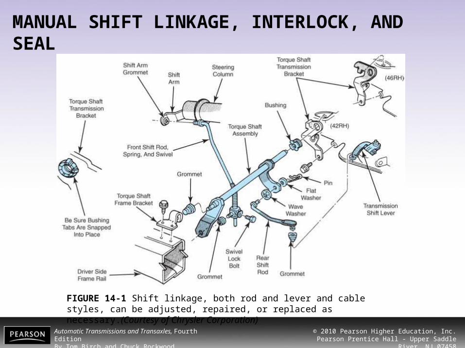
MANUAL SHIFT LINKAGE, INTERLOCK, AND SEAL• The manual shift linkage attaches to a lever on the
outside of the transmission case. • A series of rods, levers, or a cable and housing
assembly may be used. • The cable connects to a shift lever using a metal
clip or plastic grommet
Automatic Transmissions and Transaxles, Fourth EditionBy Tom Birch and Chuck Rockwood
© 2010 Pearson Higher Education, Inc.Pearson Prentice Hall - Upper Saddle River, NJ 07458
MANUAL SHIFT LINKAGE, INTERLOCK, AND SEAL
FIGURE 14-1 Shift linkage, both rod and lever and cable styles, can be adjusted, repaired, or replaced as necessary.(Courtesy of Chrysler Corporation)

Automatic Transmissions and Transaxles, Fourth EditionBy Tom Birch and Chuck Rockwood
© 2010 Pearson Higher Education, Inc.Pearson Prentice Hall - Upper Saddle River, NJ 07458
MANUAL SHIFT LINKAGE, INTERLOCK, AND SEAL
FIGURE 14-2 Access to the manual control shaft seal is obtained by removing the shift lever (a) and park-neutral position switch (b). The seal (arrow) can now be removed and replaced. (Courtesy of Toyota Motor Sales USA, Inc.)

Automatic Transmissions and Transaxles, Fourth EditionBy Tom Birch and Chuck Rockwood
© 2010 Pearson Higher Education, Inc.Pearson Prentice Hall - Upper Saddle River, NJ 07458
MANUAL SHIFT LINKAGE, INTERLOCK, AND SEAL
FIGURE 14-3 A seal can be driven out by catching the edge with a sharp chisel. Another removal method is to use a slide hammer that is threaded into the seal’s metal cage. Be careful to not damage the seal bore when using either method.
Automatic Transmissions and Transaxles, Fourth EditionBy Tom Birch and Chuck Rockwood
© 2010 Pearson Higher Education, Inc.Pearson Prentice Hall - Upper Saddle River, NJ 07458
MANUAL SHIFT LINKAGE, INTERLOCK, AND SEAL
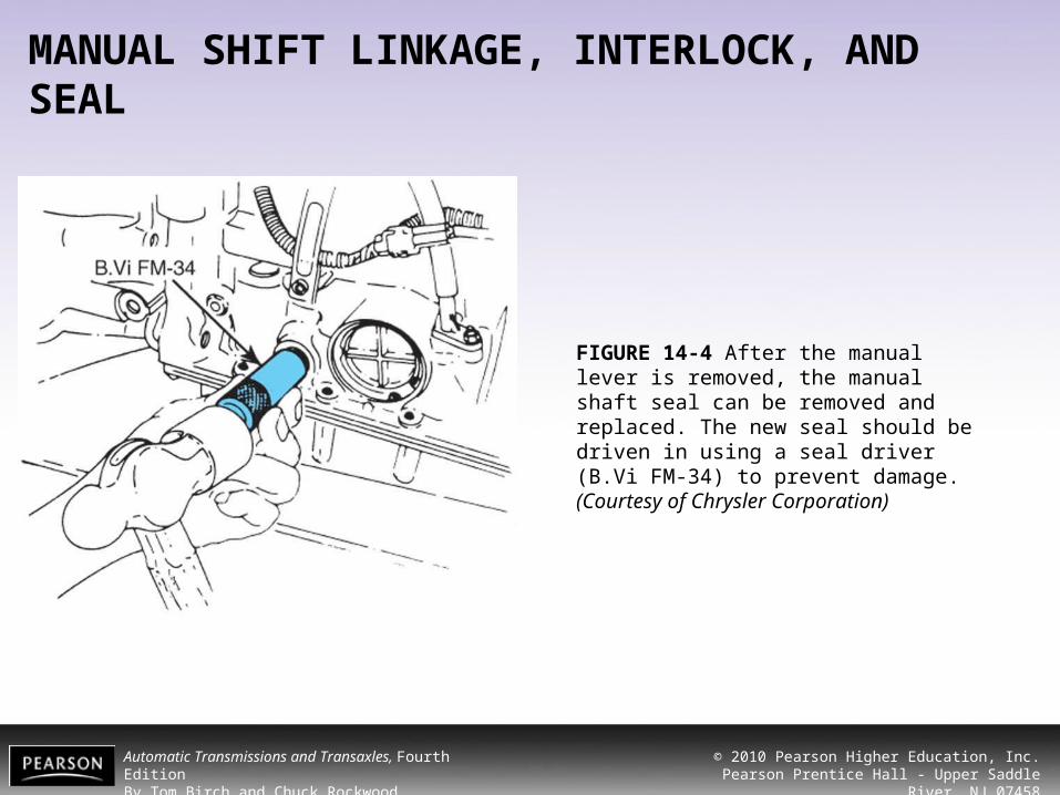
FIGURE 14-4 After the manual lever is removed, the manual shaft seal can be removed and replaced. The new seal should be driven in using a seal driver (B.Vi FM-34) to prevent damage. (Courtesy of Chrysler Corporation)
Automatic Transmissions and Transaxles, Fourth EditionBy Tom Birch and Chuck Rockwood
© 2010 Pearson Higher Education, Inc.Pearson Prentice Hall - Upper Saddle River, NJ 07458
LIP SEAL REPLACEMENT
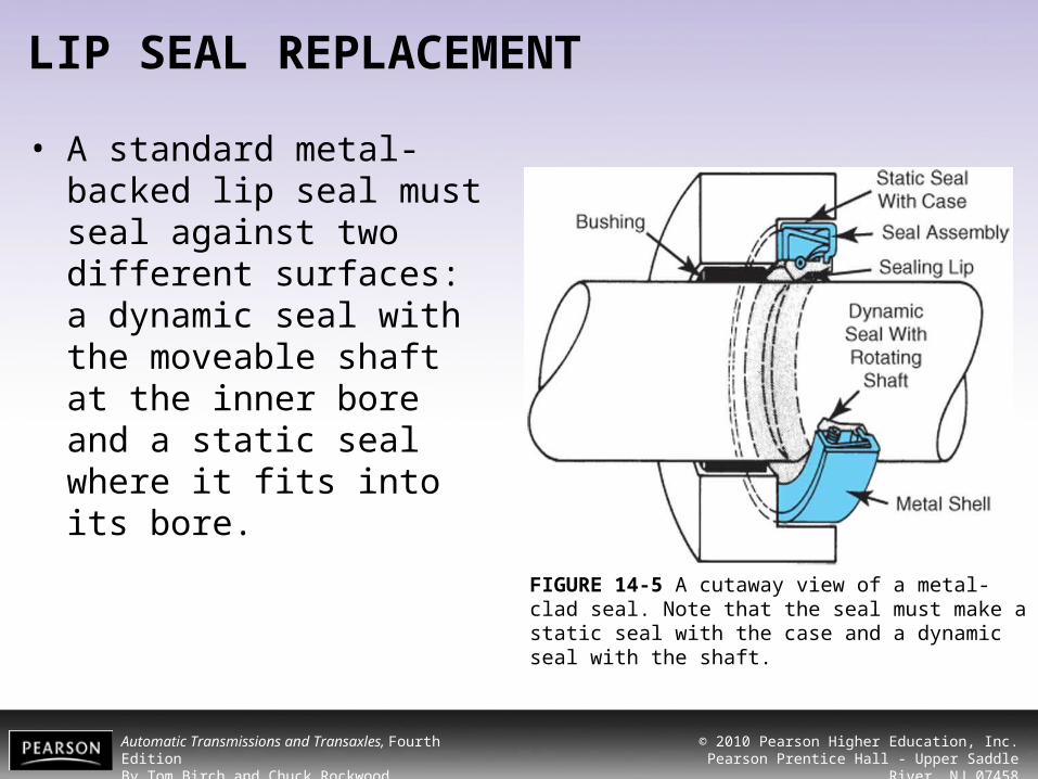
• A standard metal-backed lip seal must seal against two different surfaces: a dynamic seal with the moveable shaft at the inner bore and a static seal where it fits into its bore.
FIGURE 14-5 A cutaway view of a metal-clad seal. Note that the seal must make a static seal with the case and a dynamic seal with the shaft.

Automatic Transmissions and Transaxles, Fourth EditionBy Tom Birch and Chuck Rockwood
© 2010 Pearson Higher Education, Inc.Pearson Prentice Hall - Upper Saddle River, NJ 07458
LIP SEAL REPLACEMENT
FIGURE 14-6 This lip seal has a coating of sealant on its metal backing. Before installing an uncoated seal, a sealant should be applied to this area.
Automatic Transmissions and Transaxles, Fourth EditionBy Tom Birch and Chuck Rockwood
© 2010 Pearson Higher Education, Inc.Pearson Prentice Hall - Upper Saddle River, NJ 07458
LIP SEAL REPLACEMENT
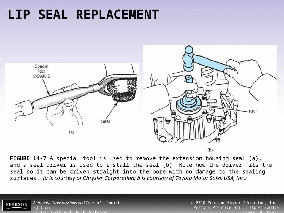
FIGURE 14-7 A special tool is used to remove the extension housing seal (a), and a seal driver is used to install the seal (b). Note how the driver fits the seal so it can be driven straight into the bore with no damage to the sealing surfaces. (a is courtesy of Chrysler Corporation; b is courtesy of Toyota Motor Sales USA, Inc.)
Automatic Transmissions and Transaxles, Fourth EditionBy Tom Birch and Chuck Rockwood
© 2010 Pearson Higher Education, Inc.Pearson Prentice Hall - Upper Saddle River, NJ 07458
TECH TIP
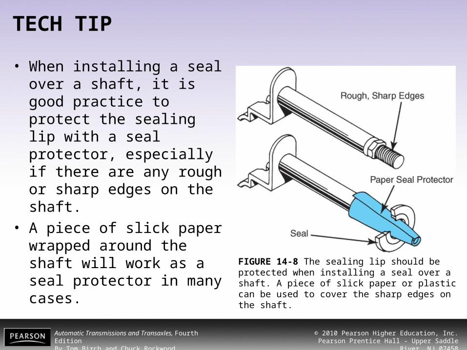
• When installing a seal over a shaft, it is good practice to protect the sealing lip with a seal protector, especially if there are any rough or sharp edges on the shaft.
• A piece of slick paper wrapped around the shaft will work as a seal protector in many cases. FIGURE 14-8 The sealing lip should be protected when
installing a seal over a shaft. A piece of slick paper or plastic can be used to cover the sharp edges on the shaft.
Automatic Transmissions and Transaxles, Fourth EditionBy Tom Birch and Chuck Rockwood
© 2010 Pearson Higher Education, Inc.Pearson Prentice Hall - Upper Saddle River, NJ 07458
TV LINKAGE AND SEAL
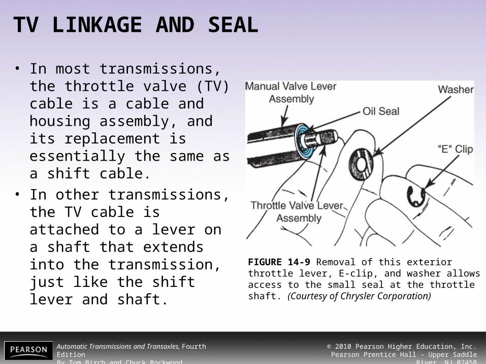
• In most transmissions, the throttle valve (TV) cable is a cable and housing assembly, and its replacement is essentially the same as a shift cable.
• In other transmissions, the TV cable is attached to a lever on a shaft that extends into the transmission, just like the shift lever and shaft.
FIGURE 14-9 Removal of this exterior throttle lever, E-clip, and washer allows access to the small seal at the throttle shaft. (Courtesy of Chrysler Corporation)

Automatic Transmissions and Transaxles, Fourth EditionBy Tom Birch and Chuck Rockwood
© 2010 Pearson Higher Education, Inc.Pearson Prentice Hall - Upper Saddle River, NJ 07458
TV LINKAGE AND SEAL
FIGURE 14-10 An O-ring seals the throttle cable where it enters the transmission case. (Courtesy of Toyota Motor Sales USA, Inc.)
Automatic Transmissions and Transaxles, Fourth EditionBy Tom Birch and Chuck Rockwood
© 2010 Pearson Higher Education, Inc.Pearson Prentice Hall - Upper Saddle River, NJ 07458
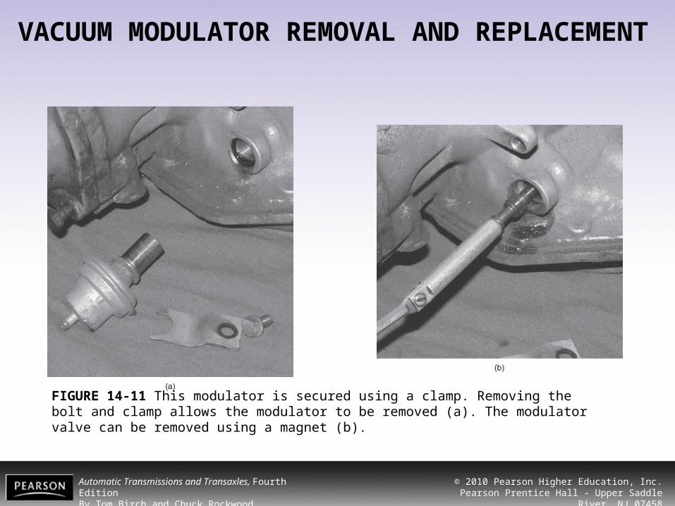
VACUUM MODULATOR REMOVAL AND REPLACEMENT• Most vacuum modulators are held in the
transmission by a bolt and retaining clamp. • Removing the clamp allows the modulator to be
pulled out of the transmission case. • Some transmissions use a control rod or pin to
connect the modulator stem to the valve.– To R&R a vacuum modulator, you should:
Automatic Transmissions and Transaxles, Fourth EditionBy Tom Birch and Chuck Rockwood
© 2010 Pearson Higher Education, Inc.Pearson Prentice Hall - Upper Saddle River, NJ 07458
VACUUM MODULATOR REMOVAL AND REPLACEMENT
FIGURE 14-11 This modulator is secured using a clamp. Removing the bolt and clamp allows the modulator to be removed (a). The modulator valve can be removed using a magnet (b).

Automatic Transmissions and Transaxles, Fourth EditionBy Tom Birch and Chuck Rockwood
© 2010 Pearson Higher Education, Inc.Pearson Prentice Hall - Upper Saddle River, NJ 07458
VACUUM MODULATOR REMOVAL AND REPLACEMENT
FIGURE 14-12 When a modulator is replaced, the retaining bolt should be tightened to the correct torque.
Automatic Transmissions and Transaxles, Fourth EditionBy Tom Birch and Chuck Rockwood
© 2010 Pearson Higher Education, Inc.Pearson Prentice Hall - Upper Saddle River, NJ 07458
ALUMINUM THREAD REPAIR
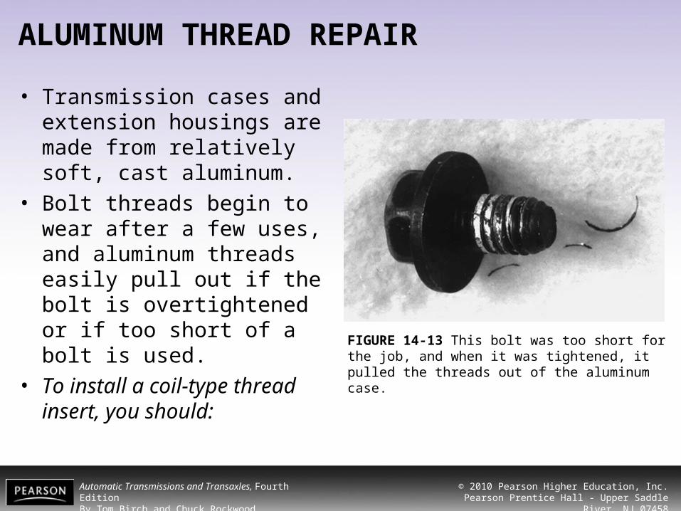
• Transmission cases and extension housings are made from relatively soft, cast aluminum.
• Bolt threads begin to wear after a few uses, and aluminum threads easily pull out if the bolt is overtightened or if too short of a bolt is used.
• To install a coil-type thread insert, you should:
FIGURE 14-13 This bolt was too short for the job, and when it was tightened, it pulled the threads out of the aluminum case.

Automatic Transmissions and Transaxles, Fourth EditionBy Tom Birch and Chuck Rockwood
© 2010 Pearson Higher Education, Inc.Pearson Prentice Hall - Upper Saddle River, NJ 07458
ALUMINUM THREAD REPAIR
• A bolt is usually designed to enter the threaded hole a distance that is about 1 1/2 to 2 times the bolt diameter.
FIGURE 14-14 The thread contact distance (CD) of a bolt should equal about twice the diameter of the threads (D) to prevent thread stripping.

Automatic Transmissions and Transaxles, Fourth EditionBy Tom Birch and Chuck Rockwood
© 2010 Pearson Higher Education, Inc.Pearson Prentice Hall - Upper Saddle River, NJ 07458
ALUMINUM THREAD REPAIR
FIGURE 14-15 Step 1 in repairing damaged threads is to drill a properly sized hole for the special tap (a). Step 2 is to use the special tap to cut new threads (b). Step 3 is to put the thread insert on the installing tool (c). Step 4 is to screw the insert into the new threads (d). The final step (not shown) is to break off the insert’s installing tang.
Automatic Transmissions and Transaxles, Fourth EditionBy Tom Birch and Chuck Rockwood
© 2010 Pearson Higher Education, Inc.Pearson Prentice Hall - Upper Saddle River, NJ 07458
ALUMINUM THREAD REPAIR
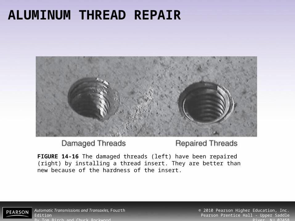
FIGURE 14-16 The damaged threads (left) have been repaired (right) by installing a thread insert. They are better than new because of the hardness of the insert.
Automatic Transmissions and Transaxles, Fourth EditionBy Tom Birch and Chuck Rockwood
© 2010 Pearson Higher Education, Inc.Pearson Prentice Hall - Upper Saddle River, NJ 07458
ELECTRICAL COMPONENT REMOVAL, REPAIR, AND REPLACEMENT
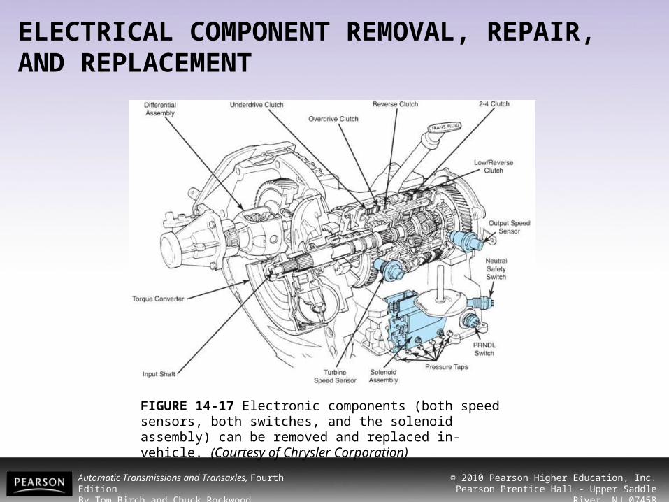
FIGURE 14-17 Electronic components (both speed sensors, both switches, and the solenoid assembly) can be removed and replaced in-vehicle. (Courtesy of Chrysler Corporation)
Automatic Transmissions and Transaxles, Fourth EditionBy Tom Birch and Chuck Rockwood
© 2010 Pearson Higher Education, Inc.Pearson Prentice Hall - Upper Saddle River, NJ 07458
ELECTRICAL COMPONENT REMOVAL, REPAIR, AND REPLACEMENT
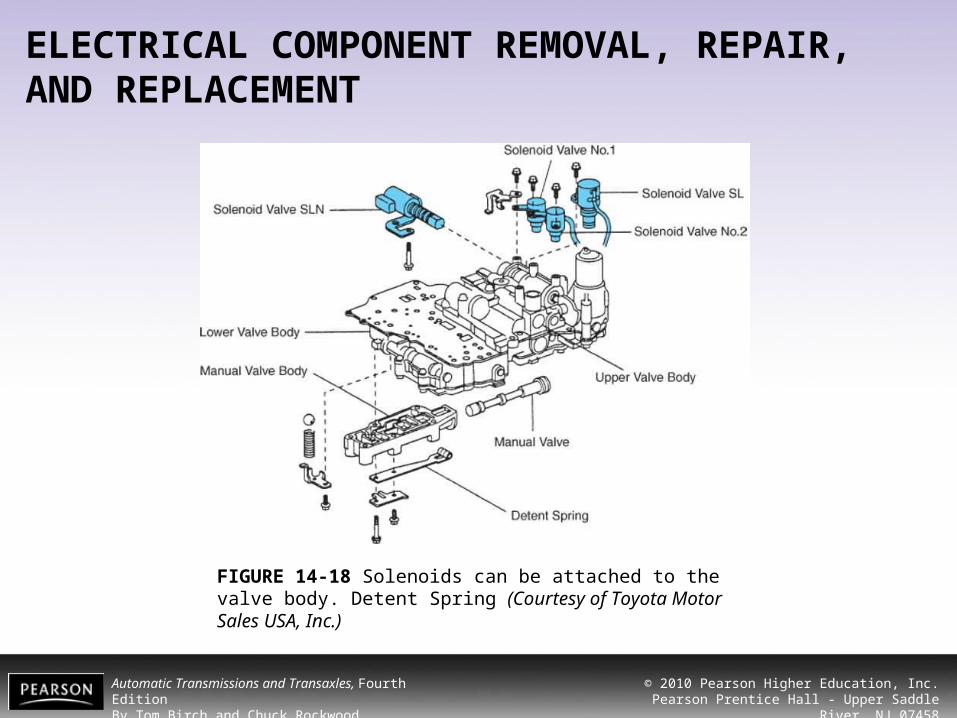
FIGURE 14-18 Solenoids can be attached to the valve body. Detent Spring (Courtesy of Toyota Motor Sales USA, Inc.)

Automatic Transmissions and Transaxles, Fourth EditionBy Tom Birch and Chuck Rockwood
© 2010 Pearson Higher Education, Inc.Pearson Prentice Hall - Upper Saddle River, NJ 07458
COOLER LINE AND FITTING REPAIR
FIGURE 14-19 If replacing the cooler lines, use care to not bend them. The fit in some vehicles is quite precise. (Courtesy of Chrysler Corporation)

Automatic Transmissions and Transaxles, Fourth EditionBy Tom Birch and Chuck Rockwood
© 2010 Pearson Higher Education, Inc.Pearson Prentice Hall - Upper Saddle River, NJ 07458
COOLER LINE AND FITTING REPAIR
FIGURE 14-20 The cooler line fittings thread into the case (a). These fittings normally have a National Pipe Thread (NPT) where they thread into the case and a flare or other style of fitting for the line connection (b).
Automatic Transmissions and Transaxles, Fourth EditionBy Tom Birch and Chuck Rockwood
© 2010 Pearson Higher Education, Inc.Pearson Prentice Hall - Upper Saddle River, NJ 07458
COOLER LINE AND FITTING REPAIR
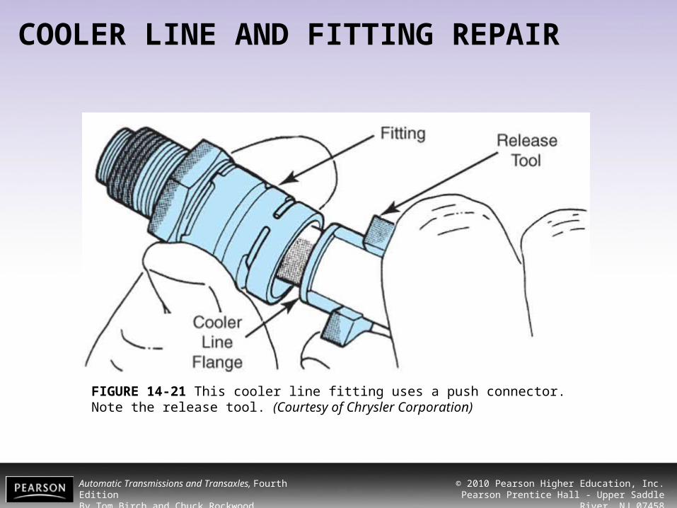
FIGURE 14-21 This cooler line fitting uses a push connector. Note the release tool. (Courtesy of Chrysler Corporation)

Automatic Transmissions and Transaxles, Fourth EditionBy Tom Birch and Chuck Rockwood
© 2010 Pearson Higher Education, Inc.Pearson Prentice Hall - Upper Saddle River, NJ 07458
TECH TIP
• Steel cooler lines have been successfully repaired by cutting out the damaged portion, flaring the cut ends, and using a flare union to rejoin the lines.
FIGURE 14-22 Cooler line damage can be repaired by removing the damaged section. A piece of steel tubing can be installed using flare (a) or compression unions
(b). A hose can also be used; it is a good practice to make a small ridge at the ends of the metal tube to
keep the hose from slipping off the tube (c).

Automatic Transmissions and Transaxles, Fourth EditionBy Tom Birch and Chuck Rockwood
© 2010 Pearson Higher Education, Inc.Pearson Prentice Hall - Upper Saddle River, NJ 07458
VALVE BODY REMOVAL AND REPLACEMENT
• There are many possibilities for valve body problems, and the valve body is removed for repairing these problems.
• This task is rather messy because removing the valve body opens many fluid passages that will begin draining.
• To remove a valve body, you should:• To replace a valve body, you should do the
following:
Automatic Transmissions and Transaxles, Fourth EditionBy Tom Birch and Chuck Rockwood
© 2010 Pearson Higher Education, Inc.Pearson Prentice Hall - Upper Saddle River, NJ 07458
TECH TIP
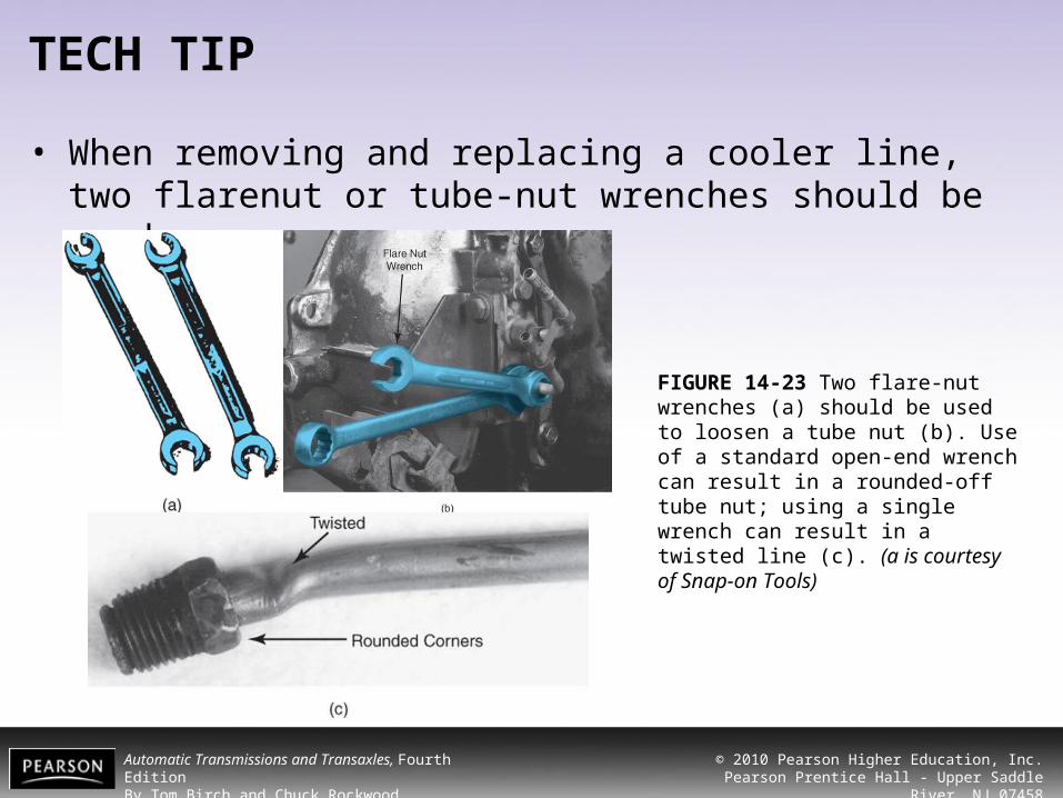
• When removing and replacing a cooler line, two flarenut or tube-nut wrenches should be used
FIGURE 14-23 Two flare-nut wrenches (a) should be used to loosen a tube nut (b). Use of a standard open-end wrench can result in a rounded-off tube nut; using a single wrench can result in a twisted line (c). (a is courtesy of Snap-on Tools)

Automatic Transmissions and Transaxles, Fourth EditionBy Tom Birch and Chuck Rockwood
© 2010 Pearson Higher Education, Inc.Pearson Prentice Hall - Upper Saddle River, NJ 07458
VALVE BODY REMOVAL AND REPLACEMENT
FIGURE 14-24 As the valve body is removed, you should be ready to catch some check balls, filter screens, or accumulator springs.

Automatic Transmissions and Transaxles, Fourth EditionBy Tom Birch and Chuck Rockwood
© 2010 Pearson Higher Education, Inc.Pearson Prentice Hall - Upper Saddle River, NJ 07458
VALVE BODY REMOVAL AND REPLACEMENT
FIGURE 14-25 The oil pan (a) and filter (b) are removed from many transmissions to gain access to the valve body. Examine the pan magnet (c) for metal chips and particles. (Courtesy of Toyota Motor Sales USA, Inc.)

Automatic Transmissions and Transaxles, Fourth EditionBy Tom Birch and Chuck Rockwood
© 2010 Pearson Higher Education, Inc.Pearson Prentice Hall - Upper Saddle River, NJ 07458
VALVE BODY REMOVAL AND REPLACEMENT
FIGURE 14-26 As the valve body is removed from many Torqueflite transmissions, the output shaft might need to be rotated so you can pull the park control rod (arrow) past the park pawl.
Automatic Transmissions and Transaxles, Fourth EditionBy Tom Birch and Chuck Rockwood
© 2010 Pearson Higher Education, Inc.Pearson Prentice Hall - Upper Saddle River, NJ 07458
VALVE BODY REMOVAL AND REPLACEMENT
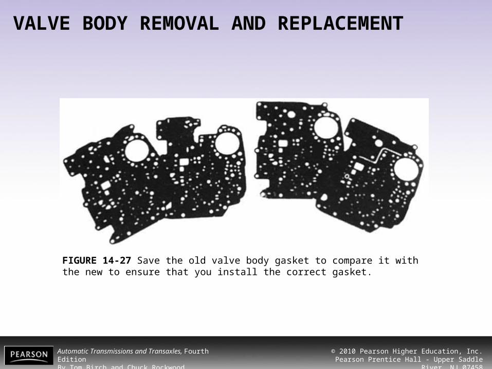
FIGURE 14-27 Save the old valve body gasket to compare it with the new to ensure that you install the correct gasket.

Automatic Transmissions and Transaxles, Fourth EditionBy Tom Birch and Chuck Rockwood
© 2010 Pearson Higher Education, Inc.Pearson Prentice Hall - Upper Saddle River, NJ 07458
VALVE BODY REMOVAL AND REPLACEMENT
FIGURE 14-28 The No. 1 gasket, transfer plate, and No. 2 gasket, along with any check balls, screens, and springs, must be positioned properly as the valve body is installed. (Courtesy of Toyota Motor Sales USA, Inc.)

Automatic Transmissions and Transaxles, Fourth EditionBy Tom Birch and Chuck Rockwood
© 2010 Pearson Higher Education, Inc.Pearson Prentice Hall - Upper Saddle River, NJ 07458
VALVE BODY REMOVAL AND REPLACEMENT
FIGURE 14-29 Two guide pins are used to ensure alignment of the gaskets, spacer plate, and valve body.

Automatic Transmissions and Transaxles, Fourth EditionBy Tom Birch and Chuck Rockwood
© 2010 Pearson Higher Education, Inc.Pearson Prentice Hall - Upper Saddle River, NJ 07458
VALVE BODY REMOVAL AND REPLACEMENT
FIGURE 14-30 This valve body is secured with bolts of four different lengths; bolts of the correct length must be placed into the proper hole.
FIGURE 14-31 Valve body bolts should be tightened in the correct order. Note that this is a spiraling pattern that goes outward from the center.

Automatic Transmissions and Transaxles, Fourth EditionBy Tom Birch and Chuck Rockwood
© 2010 Pearson Higher Education, Inc.Pearson Prentice Hall - Upper Saddle River, NJ 07458
SERVO AND ACCUMULATOR PISTON, COVER, AND SEAL SERVICE• A faulty servo piston or cover seal can cause a loss
of servo apply pressure and band slippage. • A faulty accumulator piston or cover seal can cause
poor shift quality. • A bad cover seal will leak. • The service procedures for servos and
accumulators are similar. • A leaking servo or accumulator cover can be
removed and the seal replaced. • With the cover removed, the piston and spring can
be easily removed and serviced.

Automatic Transmissions and Transaxles, Fourth EditionBy Tom Birch and Chuck Rockwood
© 2010 Pearson Higher Education, Inc.Pearson Prentice Hall - Upper Saddle River, NJ 07458
SERVO AND ACCUMULATOR PISTON, COVER, AND SEAL SERVICE
FIGURE 14-32 These four accumulators are held in the case by the valve body.

Automatic Transmissions and Transaxles, Fourth EditionBy Tom Birch and Chuck Rockwood
© 2010 Pearson Higher Education, Inc.Pearson Prentice Hall - Upper Saddle River, NJ 07458
TECH TIP
• Depending on the transmission, a special tool is sometimes required to keep the spring compressed so the cover can be removed.
FIGURE 14-33 The special tool (arrow) compresses the servo spring and holds the cover inward while the retaining ring is removed. The punch is inserted through a hole to help remove the retaining ring.
Automatic Transmissions and Transaxles, Fourth EditionBy Tom Birch and Chuck Rockwood
© 2010 Pearson Higher Education, Inc.Pearson Prentice Hall - Upper Saddle River, NJ 07458
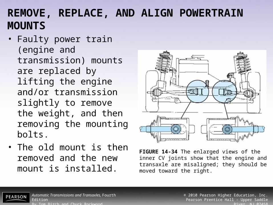
REMOVE, REPLACE, AND ALIGN POWERTRAIN MOUNTS• Faulty power train (engine
and transmission) mounts are replaced by lifting the engine and/or transmission slightly to remove the weight, and then removing the mounting bolts.
• The old mount is then removed and the new mount is installed.
FIGURE 14-34 The enlarged views of the inner CV joints show that the engine and transaxle are misaligned; they should be moved toward the right.

Automatic Transmissions and Transaxles, Fourth EditionBy Tom Birch and Chuck Rockwood
© 2010 Pearson Higher Education, Inc.Pearson Prentice Hall - Upper Saddle River, NJ 07458
EXTENSION HOUSING SEAL AND BUSHING SERVICE• The extension housing seal and bushing can be
removed and replaced with the transmission in the vehicle.
• In some cases the entire extension housing is removed for bearing, seal, governor, speedometer gear, or park mechanism service.
• A similar procedure is used to R&R the output shaft seal and bushing of a transaxle.
• To remove and replace a transmission extension housing seal, you should:

Automatic Transmissions and Transaxles, Fourth EditionBy Tom Birch and Chuck Rockwood
© 2010 Pearson Higher Education, Inc.Pearson Prentice Hall - Upper Saddle River, NJ 07458
EXTENSION HOUSING SEAL AND BUSHING SERVICE
FIGURE 14-35 It is a good practice to place alignment marks on the axle flange and rear U-joint so they can be installed in the same position.

Automatic Transmissions and Transaxles, Fourth EditionBy Tom Birch and Chuck Rockwood
© 2010 Pearson Higher Education, Inc.Pearson Prentice Hall - Upper Saddle River, NJ 07458
TECH TIP
• ATF will begin leaking out of the drive shaft opening.
• You should either raise the rear of the vehicle enough to stop the flow or place a container to catch the flow.
• A stopoff tool or old U-joint slip yoke can be used to stop the fluid leak
FIGURE 14-36 This set of plugs is used to close transmission drive shaft openings (a). A different set of
plugs is used for FWD transaxles (b). (Courtesy of ATEC Trans-Tool and Cleaning Systems)

Automatic Transmissions and Transaxles, Fourth EditionBy Tom Birch and Chuck Rockwood
© 2010 Pearson Higher Education, Inc.Pearson Prentice Hall - Upper Saddle River, NJ 07458
EXTENSION HOUSING SEAL AND BUSHING SERVICE
FIGURE 14-37 This seal is being removed using an old screwdriver. A chisel is a better tool for this. (Courtesy of Chrysler Corporation)

Automatic Transmissions and Transaxles, Fourth EditionBy Tom Birch and Chuck Rockwood
© 2010 Pearson Higher Education, Inc.Pearson Prentice Hall - Upper Saddle River, NJ 07458
EXTENSION HOUSING SEAL AND BUSHING SERVICE
FIGURE 14-38 Several styles of pullers are available to remove the rear bushing with the transmission in the vehicle. (Courtesy of OTC)
Automatic Transmissions and Transaxles, Fourth EditionBy Tom Birch and Chuck Rockwood
© 2010 Pearson Higher Education, Inc.Pearson Prentice Hall - Upper Saddle River, NJ 07458
EXTENSION HOUSING SEAL AND BUSHING SERVICE
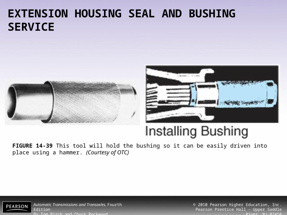
FIGURE 14-39 This tool will hold the bushing so it can be easily driven into place using a hammer. (Courtesy of OTC)
Automatic Transmissions and Transaxles, Fourth EditionBy Tom Birch and Chuck Rockwood
© 2010 Pearson Higher Education, Inc.Pearson Prentice Hall - Upper Saddle River, NJ 07458
TECH TIP
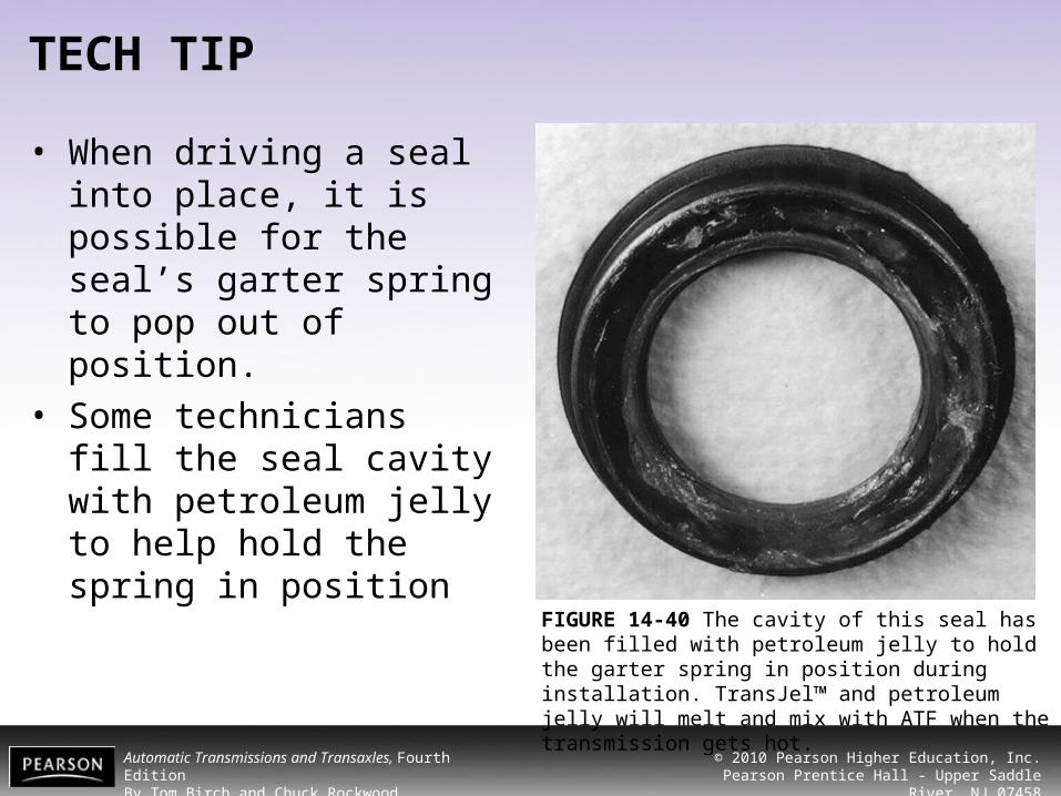
• When driving a seal into place, it is possible for the seal’s garter spring to pop out of position.
• Some technicians fill the seal cavity with petroleum jelly to help hold the spring in position
FIGURE 14-40 The cavity of this seal has been filled with petroleum jelly to hold the garter spring in position during installation. TransJel™ and petroleum jelly will melt and mix with ATF when the transmission gets hot.

Automatic Transmissions and Transaxles, Fourth EditionBy Tom Birch and Chuck Rockwood
© 2010 Pearson Higher Education, Inc.Pearson Prentice Hall - Upper Saddle River, NJ 07458
EXTENSION HOUSING REMOVAL, RWD TRANSMISSION• The extension housing is removable on most RWD
transmissions.• Depending on the transmission, extension housing
removal allows replacement of the extension housing gasket, seal, and bushing.
• The governor, speedometer gear, and park mechanism are also accessible for service with the extension housing removed.
• To remove an extension housing, you should:• To replace an extension housing, you should:
Automatic Transmissions and Transaxles, Fourth EditionBy Tom Birch and Chuck Rockwood
© 2010 Pearson Higher Education, Inc.Pearson Prentice Hall - Upper Saddle River, NJ 07458
EXTENSION HOUSING REMOVAL, RWD TRANSMISSION
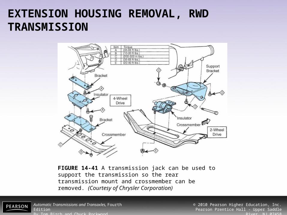
FIGURE 14-41 A transmission jack can be used to support the transmission so the rear transmission mount and crossmember can be removed. (Courtesy of Chrysler Corporation)

Automatic Transmissions and Transaxles, Fourth EditionBy Tom Birch and Chuck Rockwood
© 2010 Pearson Higher Education, Inc.Pearson Prentice Hall - Upper Saddle River, NJ 07458
EXTENSION HOUSING REMOVAL, RWD TRANSMISSION
FIGURE 14-42 After the extension housing bolts have been removed (a), the extension housing can be removed from the transmission (b).
Automatic Transmissions and Transaxles, Fourth EditionBy Tom Birch and Chuck Rockwood
© 2010 Pearson Higher Education, Inc.Pearson Prentice Hall - Upper Saddle River, NJ 07458
EXTENSION HOUSING REMOVAL, RWD TRANSMISSION• Speedometer Gear Replacement
– Speedometer gear problems show up as a nonoperating speedometer.
– The cause can be a faulty cable, driven gear, or drive gear.
– On some transmissions, the speedometer drive gear is a set of teeth cut into the output shaft.
– On these transmissions, a rough drive gear can sometimes be cured using a three-corner file.
Automatic Transmissions and Transaxles, Fourth EditionBy Tom Birch and Chuck Rockwood
© 2010 Pearson Higher Education, Inc.Pearson Prentice Hall - Upper Saddle River, NJ 07458
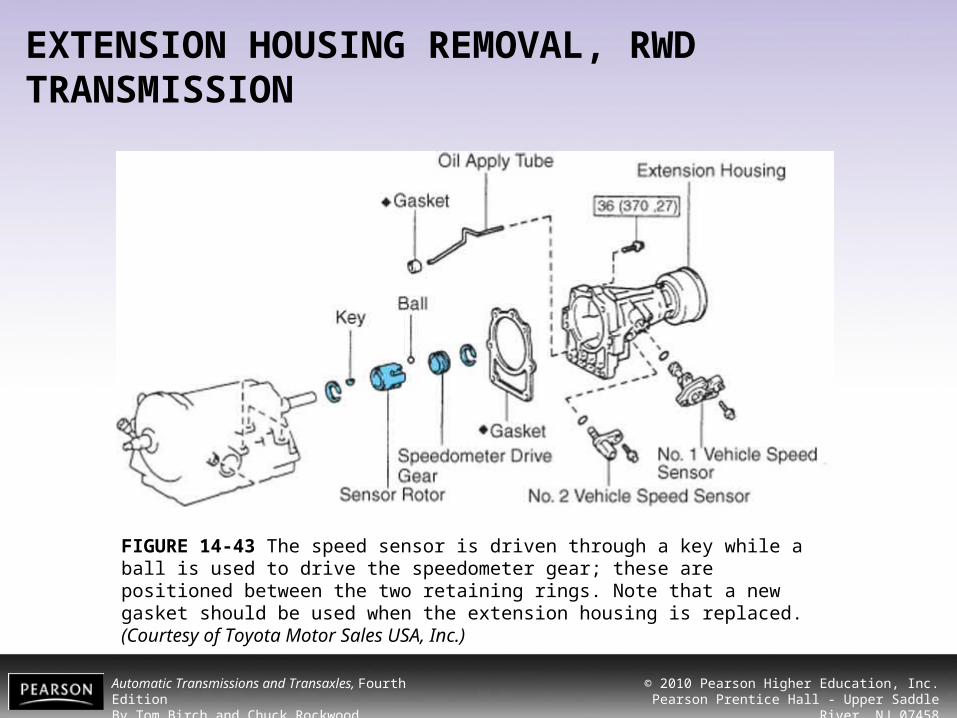
EXTENSION HOUSING REMOVAL, RWD TRANSMISSION
FIGURE 14-43 The speed sensor is driven through a key while a ball is used to drive the speedometer gear; these are positioned between the two retaining rings. Note that a new gasket should be used when the extension housing is replaced. (Courtesy of Toyota Motor Sales USA, Inc.)
Automatic Transmissions and Transaxles, Fourth EditionBy Tom Birch and Chuck Rockwood
© 2010 Pearson Higher Education, Inc.Pearson Prentice Hall - Upper Saddle River, NJ 07458
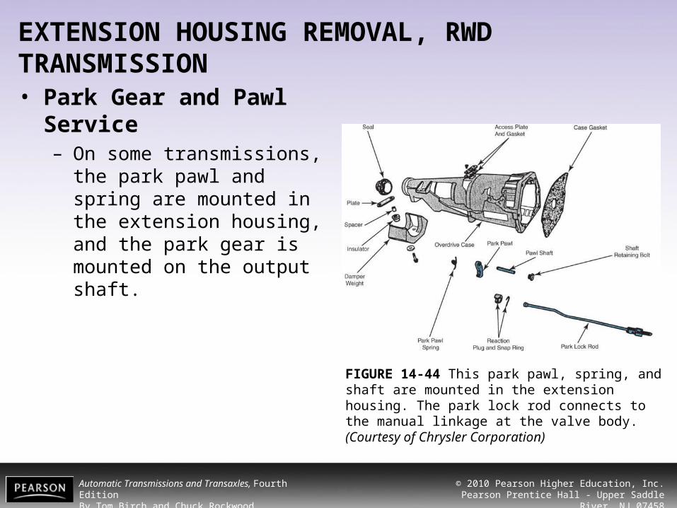
EXTENSION HOUSING REMOVAL, RWD TRANSMISSION• Park Gear and Pawl
Service– On some transmissions, the
park pawl and spring are mounted in the extension housing, and the park gear is mounted on the output shaft.
FIGURE 14-44 This park pawl, spring, and shaft are mounted in the extension housing. The park lock rod connects to the manual linkage at the valve body. (Courtesy of Chrysler Corporation)

Automatic Transmissions and Transaxles, Fourth EditionBy Tom Birch and Chuck Rockwood
© 2010 Pearson Higher Education, Inc.Pearson Prentice Hall - Upper Saddle River, NJ 07458
GOVERNOR SERVICE
• If the governor is shaft driven, removal of the extension housing allows access to the governor for inspection or disassembly and cleaning.
FIGURE 14-45 The governor is mounted onto the governor support/park gear of this Torqueflite transmission. (Courtesy of Chrysler Corporation)
Automatic Transmissions and Transaxles, Fourth EditionBy Tom Birch and Chuck Rockwood
© 2010 Pearson Higher Education, Inc.Pearson Prentice Hall - Upper Saddle River, NJ 07458
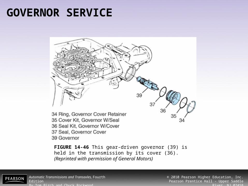
GOVERNOR SERVICE
FIGURE 14-46 This gear-driven governor (39) is held in the transmission by its cover (36). (Reprinted with permission of General Motors)

Automatic Transmissions and Transaxles, Fourth EditionBy Tom Birch and Chuck Rockwood
© 2010 Pearson Higher Education, Inc.Pearson Prentice Hall - Upper Saddle River, NJ 07458
GOVERNOR SERVICE
FIGURE 14-47 After the cover has been removed (a), this governor can be slid out of its bore (b).

Automatic Transmissions and Transaxles, Fourth EditionBy Tom Birch and Chuck Rockwood
© 2010 Pearson Higher Education, Inc.Pearson Prentice Hall - Upper Saddle River, NJ 07458
GOVERNOR SERVICE
FIGURE 14-48 An apple-cored governor gear can cause erratic or no governor operation. This is usually caused by a rough or damaged drive gear or a governor that is trying to seize in the bore. (Reprinted with permission of General Motors)
FIGURE 14-49 This governor cover is a force-fit. An old C6 servo cover is the right size to use as a driving tool for a THM 350 governor cover.

Automatic Transmissions and Transaxles, Fourth EditionBy Tom Birch and Chuck Rockwood
© 2010 Pearson Higher Education, Inc.Pearson Prentice Hall - Upper Saddle River, NJ 07458
GOVERNOR SERVICE
• Governor Disassembly– A shaft-driven governor
usually consists of the governor body, valve(s), weight(s), support, and sometimes a spring or shaft/pin is used to connect the weight to the valve.
FIGURE 14-50 This speed sensor rotor (90) is held in place by a retaining ring and is driven by a key (91) in
the output shaft (a). Some governors use a pin that passes through the output shaft to connect the weight
to the valve (b). (Courtesy of Chrysler Corporation)

Automatic Transmissions and Transaxles, Fourth EditionBy Tom Birch and Chuck Rockwood
© 2010 Pearson Higher Education, Inc.Pearson Prentice Hall - Upper Saddle River, NJ 07458
GOVERNOR SERVICE
FIGURE 14-51 A typical early General Motors governor that has been disassembled for cleaning or repair.

Automatic Transmissions and Transaxles, Fourth EditionBy Tom Birch and Chuck Rockwood
© 2010 Pearson Higher Education, Inc.Pearson Prentice Hall - Upper Saddle River, NJ 07458
GOVERNOR SERVICE
FIGURE 14-52 With the governor weights fully extended, there should be a minimum opening of 0.020 in. at the entry port (a). With the weights fully inward, there should be a minimum opening of 0.020 in. at the exhaust port (b).
Automatic Transmissions and Transaxles, Fourth EditionBy Tom Birch and Chuck Rockwood
© 2010 Pearson Higher Education, Inc.Pearson Prentice Hall - Upper Saddle River, NJ 07458
GOVERNOR SERVICE
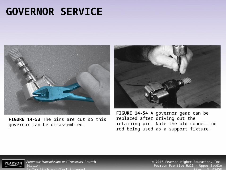
FIGURE 14-53 The pins are cut so this governor can be disassembled.
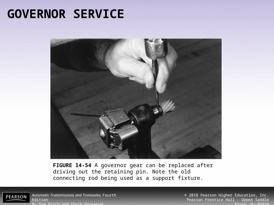
FIGURE 14-54 A governor gear can be replaced after driving out the retaining pin. Note the old connecting rod being used as a support fixture.
Automatic Transmissions and Transaxles, Fourth EditionBy Tom Birch and Chuck Rockwood
© 2010 Pearson Higher Education, Inc.Pearson Prentice Hall - Upper Saddle River, NJ 07458
GOVERNOR SERVICE
FIGURE 14-54 A governor gear can be replaced after driving out the retaining pin. Note the old connecting rod being used as a support fixture.

Automatic Transmissions and Transaxles, Fourth EditionBy Tom Birch and Chuck Rockwood
© 2010 Pearson Higher Education, Inc.Pearson Prentice Hall - Upper Saddle River, NJ 07458
SUMMARY
1. Many transmission problems can be repaired without removing the transmission from the vehicle.
2. The pan should be removed and its contents carefully checked before removing a transmission from a vehicle.
3. Components that can be serviced without removing the transmission include linkage adjustment and repair, seal replacement, governor service and replacement, valve body repair, and transmission mounts, to name a few.
4. After making any repair, carefully check your work and road test the vehicle for proper operation.

Automatic Transmissions and Transaxles, Fourth EditionBy Tom Birch and Chuck Rockwood
© 2010 Pearson Higher Education, Inc.Pearson Prentice Hall - Upper Saddle River, NJ 07458
REVIEW QUESTIONS
1. The replacement of the manual linkage cable or the throttle cable is always followed by a cable _________.
2. Shift linkage _________ is a safety mechanism that prevents a vehicle from being shifted out of park unless the key is in the ignition and the brake is applied.
3. To prevent damage to a seal during installation, a _________ driver should be used.
4. A handy trick to keep a seal spring from coming out on installation is to fill the recess with _________ _________.
5. Thread damage can be caused by using a bolt that is _________ _________ or _________ _________.
Automatic Transmissions and Transaxles, Fourth EditionBy Tom Birch and Chuck Rockwood
© 2010 Pearson Higher Education, Inc.Pearson Prentice Hall - Upper Saddle River, NJ 07458
REVIEW QUESTIONS
6. When removing a cooler line, a _________ wrench must be used.
7. It is important that the _________ of each bolt be noted as a valve body is removed.
8. A special _________ and _________ tool is usually required for on-vehicle bushing replacement.
9. A governor can be serviced by carefully _________, cleaning the parts, and _________.
10. The actual procedures of removal and replacement of various transmission components varies between manufacturers. Always check the _________ manual if in doubt about a service procedure.
Automatic Transmissions and Transaxles, Fourth EditionBy Tom Birch and Chuck Rockwood
© 2010 Pearson Higher Education, Inc.Pearson Prentice Hall - Upper Saddle River, NJ 07458
CHAPTER QUIZ
1. Student A says that a faulty governor can be repaired with the transmission in the car. Student B agrees, but says that geardriven governors require removal of the extension housing. Who is correct?a) Student A
b) Student B
c) Both A and B
d) Neither A nor B
Automatic Transmissions and Transaxles, Fourth EditionBy Tom Birch and Chuck Rockwood
© 2010 Pearson Higher Education, Inc.Pearson Prentice Hall - Upper Saddle River, NJ 07458
CHAPTER QUIZ
2. Which of these operations cannot usually be done with the transmission in the car?a) Valve body removal and replacement
b) Manual shift linkage seal replacement
c) Torque converter seal replacement
d) Vacuum modulator replacement
Automatic Transmissions and Transaxles, Fourth EditionBy Tom Birch and Chuck Rockwood
© 2010 Pearson Higher Education, Inc.Pearson Prentice Hall - Upper Saddle River, NJ 07458
CHAPTER QUIZ
3. Student A says that a seal can be pried out of a bore using a sharp chisel. Student B says that smaller metal-backed seals can often be driven into place using a standard socket. Who is correct?a) Student A
b) Student B
c) Both A and B
d) Neither A nor B

Automatic Transmissions and Transaxles, Fourth EditionBy Tom Birch and Chuck Rockwood
© 2010 Pearson Higher Education, Inc.Pearson Prentice Hall - Upper Saddle River, NJ 07458
CHAPTER QUIZ
4. Student A says that a metal-backed seal has to seal against two surfaces, the housing bore and shaft. Student B says that a sealing lip is used to seal the backing to the housing bore. Who is correct?a) Student A
b) Student B
c) Both A and B
d) Neither A nor B

Automatic Transmissions and Transaxles, Fourth EditionBy Tom Birch and Chuck Rockwood
© 2010 Pearson Higher Education, Inc.Pearson Prentice Hall - Upper Saddle River, NJ 07458
CHAPTER QUIZ
5. Student A says that a new seal will be ruined if the lip is cut during installation. Student B says that the seal lip should be lubricated with petroleum jelly or ATF before installing. Who is correct?a) Student A
b) Student B
c) Both A and B
d) Neither A nor B

Automatic Transmissions and Transaxles, Fourth EditionBy Tom Birch and Chuck Rockwood
© 2010 Pearson Higher Education, Inc.Pearson Prentice Hall - Upper Saddle River, NJ 07458
CHAPTER QUIZ
6. Student A says that all throttle/kickdown linkages pass into the case through a metal-backed lip seal. Student B says that all the cable or rods connect to a lever on the outside of the case. Who is correct?a) Student A
b) Student B
c) Both A and B
d) Neither A nor B

Automatic Transmissions and Transaxles, Fourth EditionBy Tom Birch and Chuck Rockwood
© 2010 Pearson Higher Education, Inc.Pearson Prentice Hall - Upper Saddle River, NJ 07458
CHAPTER QUIZ
7. Student A says that stripped threads in an aluminum case can be repaired by installing a thread insert. Student B says that a 1/4-in. bolt should have at least 3/8 in. of thread contact. Who is correct?a) Student A
b) Student B
c) Both A and B
d) Neither A nor B
Automatic Transmissions and Transaxles, Fourth EditionBy Tom Birch and Chuck Rockwood
© 2010 Pearson Higher Education, Inc.Pearson Prentice Hall - Upper Saddle River, NJ 07458
CHAPTER QUIZ
8. Student A says that the best repair for a kinked, leaky cooler line is to cut out the damaged section and replace it with copper tubing. Student B says that you should always use two wrenches to loosen a tube nut. Who is correct?a) Student A
b) Student B
c) Both A and B
d) Neither A nor B
Automatic Transmissions and Transaxles, Fourth EditionBy Tom Birch and Chuck Rockwood
© 2010 Pearson Higher Education, Inc.Pearson Prentice Hall - Upper Saddle River, NJ 07458
CHAPTER QUIZ
9. Student A says that you need to be careful not to lose any of the check balls when you remove a valve body. Student B says that a transmission must be upside down before removing the valve body. Who is correct?a) Student A
b) Student B
c) Both A and B
d) Neither A nor B
Automatic Transmissions and Transaxles, Fourth EditionBy Tom Birch and Chuck Rockwood
© 2010 Pearson Higher Education, Inc.Pearson Prentice Hall - Upper Saddle River, NJ 07458
CHAPTER QUIZ
10.Some valve bodies have a spring pressure from a (the) _________ that will move them when the bolts are loosened.a) servo or an accumulator
b) servo or a relief valve
c) shift valves or a servo
d) pump relief valve or an accumulator
Automatic Transmissions and Transaxles, Fourth EditionBy Tom Birch and Chuck Rockwood
© 2010 Pearson Higher Education, Inc.Pearson Prentice Hall - Upper Saddle River, NJ 07458
CHAPTER QUIZ
11.Student A says that you should carefully place the bolts with the correct length into the proper holes as a valve body is replaced. Student B says that the valve body bolts should always be carefully torqued. Who is correct?a) Student A
b) Student B
c) Both A and B
d) Neither A nor B
Automatic Transmissions and Transaxles, Fourth EditionBy Tom Birch and Chuck Rockwood
© 2010 Pearson Higher Education, Inc.Pearson Prentice Hall - Upper Saddle River, NJ 07458
CHAPTER QUIZ
11.Student A says that you should carefully place the bolts with the correct length into the proper holes as a valve body is replaced. Student B says that the valve body bolts should always be carefully torqued. Who is correct?a) Student A
b) Student B
c) Both A and B
d) Neither A nor B

Automatic Transmissions and Transaxles, Fourth EditionBy Tom Birch and Chuck Rockwood
© 2010 Pearson Higher Education, Inc.Pearson Prentice Hall - Upper Saddle River, NJ 07458
CHAPTER QUIZ
12.Student A says that all servo covers are held in place by a group of three or four bolts. Student B says that many servos contain a spring that must be kept compressed while the cover is removed. Who is correct?a) Student A
b) Student B
c) Both A and B
d) Neither A nor B
Automatic Transmissions and Transaxles, Fourth EditionBy Tom Birch and Chuck Rockwood
© 2010 Pearson Higher Education, Inc.Pearson Prentice Hall - Upper Saddle River, NJ 07458
CHAPTER QUIZ
13.Which of the following is not a reason for removing an extension housing on a General Motors RWD vehicle?a) Speedometer driven-gear replacement
b) Governor replacement
c) Park pawl or spring replacement
d) Extension housing bushing replacement

Automatic Transmissions and Transaxles, Fourth EditionBy Tom Birch and Chuck Rockwood
© 2010 Pearson Higher Education, Inc.Pearson Prentice Hall - Upper Saddle River, NJ 07458
CHAPTER QUIZ
14.Student A says that you need to lift the transmission slightly in order to remove the rear mount and extension housing. Student B says that all transmissions use a paper gasket between the extension housing and case. Who is correct?a) Student A
b) Student B
c) Both A and B
d) Neither A nor B
Automatic Transmissions and Transaxles, Fourth EditionBy Tom Birch and Chuck Rockwood
© 2010 Pearson Higher Education, Inc.Pearson Prentice Hall - Upper Saddle River, NJ 07458
CHAPTER QUIZ
15.Student A says that a faulty governor gear can keep a transmission from upshifting. Student B says that it is possible to disassemble a governor so it can be thoroughly cleaned and repaired. Who is correct?a) Student A
b) Student B
c) Both A and B
d) Neither A nor B
Related Documents