Objective Questions Electrical Engineering Old pagination 1) Resistivity of a wire depends on A. material B. length C. cross section area D. all of above A B C D Submit RESET EXP LANATION GET ANSWER Resistivity is a basic property of any materials. It is defined as the resistance offered by a cube of unit volume of the materials. Hence resistivity of a wire depends on its material. 2) When n numbers resistances of each value r are connected in parallel, then the resultant resistance is x. When these n resistances are connected in series, total resistance is A. nx. B. n 2 x. C. x/n. D. rnx. A B C D CHE CK ANSWER RESET Reset GET ANSWER n numbers resistances of each value r are connected in parallel, then the resultant resistance is x, that means r/n = x ⇒ r = nx.When these n resistances are connected in series, total resistance is nr = n.(nx) = n 2 x [Since r = nx alraedy proved] 3) Resistance of a wire is r ohms. The wire is stretched to doub le its length, then its resistance will be

Welcome message from author
This document is posted to help you gain knowledge. Please leave a comment to let me know what you think about it! Share it to your friends and learn new things together.
Transcript

7/21/2019 Objective Questions Electrical Engineering.pdf
http://slidepdf.com/reader/full/objective-questions-electrical-engineeringpdf 1/150
Objective Questions Electrical Engineering Old pagination
1) Resistivity of a wire depends on
A. materia
B. length
C. cross section area
D. all of above
A B C D
Submit
RESET
EXPLANATION
GET ANSWER
Resistivity is a basic property of any materials. It is defined as the resistance offered by a cube of unit volume ofthe materials. Hence resistivity of a wire depends on its material.
2) When n numbers resistances of each value r are connected in parallel, then the resultant resistance is x. Whenthese n resistances are connected in series, total resistance is
A. nx
B. n2x
C. x/n.
D. rnx.
A B C D
CHECK ANSWER
RESET
Reset
GET ANSWER
n numbers resistances of each value r are connected in parallel, then the resultant resistance is x, that means r/n= x ⇒ r = nx.When these n resistances are connected in series, total resistance is nr = n.(nx) = n 2x [Since r = nxalraedy proved]
3) Resistance of a wire is r ohms. The wire is stretched to double its length, then its resistance will be

7/21/2019 Objective Questions Electrical Engineering.pdf
http://slidepdf.com/reader/full/objective-questions-electrical-engineeringpdf 2/150
A. r/2
B. 4r
C. 2r
D. r/4
A B C D
CHECK ANSWER
Reset
EXPLANATION
Reset
Resistance r = ρl/a. When the wire of length l is stretched to 2l, then the cross - sectional area of the wirebecomes a/2. Now new value of resistance, r' = ρ2l/(a/2) = 4ρl/a = 4r.
4) Kirchhoff's second law is based on law of conservation of
A. charge
B. energy
C. momentum
D. mass
A B C D
CHECK ANSWER
RESET
EXPLANATION
GET ANSWER
Kirchhoff's voltage law (KVL) is also called Kirchhoff's second law. The principle of conservation of energyimplies that the directed sum of the electrical potential differences (voltage) around any closed network is zero.
5) One coulomb of electrical charge is contributed by how many electrons ?
A. 0.625 X 10¹⁹
B. 1.6 X 10¹⁹
C. 1019
D. 1.6 X 10¹².
A B C D

7/21/2019 Objective Questions Electrical Engineering.pdf
http://slidepdf.com/reader/full/objective-questions-electrical-engineeringpdf 3/150
CHECK ANSWER
RESET
EXPLANATION
GET ANSWER
Electrical charge of one electron is 1.6 X 10 - 19 coulomb, hence one coulomb implies 1/(1.6 X 10 - 19) or 0.625 X10¹⁹ numbers of electrons.
6) Tow bulbs marked 200 watts - 250 V, and 100 watts - 250 V are joined in series to 250 V supply. The powerconsumed by the circuit is
A. 33 watt
B. 200 wat
C. 300 wat
D. 67 watt.
A B C D
CHECK ANSWER
RESET
EXPLANATION
GET ANSWER
The resistance of first and second bulb are (250)2/200 and (250)2/100 Ω respectively. The total resistance whenthe bulbs are connected in series will be (250) 2/200 + (250)2/100 Ω. The total power consumption when they joined in series to 250 V supply. The power consumed in the circuit will be (250)2/(250)2(1/200 + 1/100) =20000/300 = 67 watt.
7) Ampere second is the unit of
A. conductance
B. powe
C. energy
D. charge
A B C D
CHECK ANSWER
RESET
EXPLANATION
GET ANSWER
Electrical current is transfer electrical charge per second. Therefore Ampere = coulomb/second hence coulomb =ampere X second or ampere second.
8) Which of the following is not the unit of electrical power

7/21/2019 Objective Questions Electrical Engineering.pdf
http://slidepdf.com/reader/full/objective-questions-electrical-engineeringpdf 4/150
A. volt/ampere
B. volt ampere
C. wat
D. joule/second
A B C D
CHECK ANSWER
RESET
EXPLANATION
GET ANSWER
Unit of electrical power is watt and watt means joule/second. Again electrical power = voltage X current, hencevolt ampere may be another expression for unit of power. But impedance = voltage/current, hence volt/amperemay be expression for unit of impedance not power.
9) One kilowatt hour is same as
A. 36 X 105 wat
B. 36 X 105 ergs
C. 36 X 105 joules
D. 36 X 105 BTU
A B C D
CHECK ANSWER
RESET
EXPLANATION
GET ANSWER
Kilowatt hour is the unit of energy and 1 kilowatt hour = 1000 X 1 watt X 3600 second = 36 X 105 watt second= 36 X 105 joule.
10) An electric current of 6 A is same as
A. 6 joule/second
B. 6 Coulomb/second
C. 6 watt/second
D. none of the above.

7/21/2019 Objective Questions Electrical Engineering.pdf
http://slidepdf.com/reader/full/objective-questions-electrical-engineeringpdf 5/150
A B C D
CHECK ANSWER
RESET
EXPLANATION
GET ANSWER
Current is rate of charge transferred per second. A current of 6 ampere implies 6 coulomb charge transferred
through a cross section of conductor per second. Therefore 6 Ampere = 6 coulomb/second.
11) A circuit contains two un equal resistor in parallel
A. voltage drops across both are same
B. currents in both are same
C. heat losses in both are same
D. voltage drops are according to their resistive value
A B C D
CHECK ANSWER
RESET
EXPLANATION
GET ANSWER
Whatever may be the value of resistance the voltage drops, across all the resistors connected in parallel, arealways same
12) Conductance of any conductor is expressed as
A. ampere/wat
B. mho
C. volt2 /wat
D. watt/ampere2
A B C D
CHECK ANSWER
RESET
EXPLANATION
GET ANSWER
Conductance is reciprocal of resistance that means conductance = (resistance) - 1 . Hence unit of conductance wilbe 1/ohm and this is known as mho

7/21/2019 Objective Questions Electrical Engineering.pdf
http://slidepdf.com/reader/full/objective-questions-electrical-engineeringpdf 6/150
13) A copper wire of length l and diameter d has potential difference V applied at its two ends. The drift velocity is v d
If the diameter of the wire is made d/2, then the drift velocity becomes
A. vd
B. 4vd
C. vd /4
D. vd /2.
A B C D
CHECK ANSWER
RESET
EXPLANATION
GET ANSWER
The drift velocity is a basic property of conductor material and hence it does not depend upon the length ordiameter of the conductor.
14) Two resistances R1 and R2 give combined resistances 4.5Ω and 1Ω when they are connected in series andparallel respectively. What would be the values of these resistances ?
A. 3Ω and 6Ω
B. 1.5Ω and 3Ω
C. 3Ω and 9Ω
D. 6Ω and 9Ω
A B C D
CHECK ANSWER
RESET
EXPLANATION
GET ANSWER
Here, R1 + R2 = 4.5..................(1)and R1.R2/(R1 + R2) = 1⇒ R1.R2/4.5 = 1⇒ R1.R2 = 4.5 ......................(2)Combining (1) & (2) we get R1 = 1.5 Ω or 3 Ω and R2 = 3 Ω or 1.5 Ω
15) Which of the following may be value of resistivity of copper
A. 1.7 X 10 -
B. 1.7 X 10 -
C. 1.7 X 10 -

7/21/2019 Objective Questions Electrical Engineering.pdf
http://slidepdf.com/reader/full/objective-questions-electrical-engineeringpdf 7/150
D. 1.7 X 10 - 3.
A B C D
CHECK ANSWER
RESET
EXPLANATION
GET ANSWER
The value of resistivity of copper is 1.7 X 10 - 6
16) Mass of a proton is how many times greater than mass of an electron
A. 184000
B. 18400
C. 1840
D. 184
A B C D
CHECK ANSWER
RESET
EXPLANATION
GET ANSWER
Mass of a proton is 1840 times greater than mass of an electron.
Multiple Choice Questions on Electric Current Old pagination
1. One coulomb of electrical charge is contributed by how many electrons ?
A. 0.625 X 10¹⁹.
B. 1.6 X 10¹⁹.
C. 1019.
D. 1.6 X 10¹².
Electrical charge of one electron is - 1.6 X 10 - 19 coulomb, hence one coulomb implies1 / | - 1.6 X 10 - 19 | or 0.625 X 10¹⁹ number of electrons.
2. 5 X 10¹⁶ electrons pass across the section of a conductor in 1 minutes and 20 seconds. The current flowingis

7/21/2019 Objective Questions Electrical Engineering.pdf
http://slidepdf.com/reader/full/objective-questions-electrical-engineeringpdf 8/150
. 0.1 mA.
A. 1 mA.
B. 10 mA.
C. 100 mA.
The charge of an electron is - 1.6 X 10 -19 coulomb. Therefore total negative charge passes across thesection of a conductor in 1 minute and 20 seconds is5 X 1016 X 1.6 X 10-19 = 8 X 10 - 3. Therefore, charge passes across the section in one second, is 8 X 10³ coulomb/80 second = 10 - 4 coulomb/second (or Amp) = 0.1 mA.
3. An electric current of 6 A is same as
. 6 joule/second.
A.
6 Coulomb/second.
B. 6 watt/second.
C. none of the above.
Current is the rate of charge transferred per second. A current of 6 ampere implies 6 coulomb chargetransferred through a cross section of conductor per second. Therefore 6 ampere = 6 coulomb/second.
4. Ampere-second is the unit of
. conductance.
A. power.
B. energy.
C. charge.
Electrical current is nothing but rate of flow of charge per second. Therefore, ampere = coulomb/second
hence coulomb = ampere × second or ampere-second.
5. The current in a circuit follows the relation i = 100sinωt. If frequency is 25 Hz how long will it take for thecurrent to rise to 50 A ?
. 1 ms.
A. 3.33 ms.
B. 10 ms.

7/21/2019 Objective Questions Electrical Engineering.pdf
http://slidepdf.com/reader/full/objective-questions-electrical-engineeringpdf 9/150
C. 20 ms.
Let, at t second the instantaneous value of current i = 50A.∴ 50 = 100sinΩor, sinωt = 1/2or, ωt = &pi ⁄ 6Now, ω = 2π.f = 2πX25 = 50π , [Since frequency f = 25 Hz.]Therefore, t = π ⁄ (50X6Xπ) = 1 ⁄ 300 second = 3.33 ms.
6. The equation of a current is given by i = Imsin2ωt. The frequency of the current in Hz is
. ω ⁄ 2π.
A. ω ⁄ 2.
B. 2ω ⁄ π.
C. ω ⁄ π.
The general equation of a current wave is i = I msinωt = I msin2πf.t .....(1)Where, f is the frequency of the current wave. Here, the given equation isi = I msin2ωt......(2)Comparing, (1) & (2) we get, 2ωt = 2πft or, ω = π.f or, f = ω ⁄ π
7. The equation of alternating current is i = 42.4sin628t. Then the average value of current is
.
42.42 A.
A. 27 A.
B. 38 A.
C. 22 A.
The relation between average value and peak value of a sinusoidal waveform is given by
Here, I m = 42.4 A Therefore, I 0 = 0.636X42.4 = 26.97 A
8. If 1 A current is flowing through a series circuit having 100 resistors of each having resistance of 1 Ω. Whatwill be the current in the circuit where, these 100 resistors are connected in parallel ?
. 10 A.
A. 100 A.

7/21/2019 Objective Questions Electrical Engineering.pdf
http://slidepdf.com/reader/full/objective-questions-electrical-engineeringpdf 10/150
B. 1000 A.
C. 10000 A.
Let , the applied voltage across the circuit be V. Therefore, current of1A = V/(100 X 1 Ω)=100 V
Now when these 100 resistors of each 1 Ω will be connected in parallel, the equivalent resistance ofcombined circuit will be 1/100=0.01 ohmNow, the current will be V/R=100/0.01=100×100= 104 A.
9. In the figure shown, what will be the current passing through 2 Ω resistor ?
. 0.25 A.
A. 0.75 A.
B.
0.5 A.
C. 1 A.
According to current division law, required current
10. A copper conductor of one square millimetre can safely carry a current of
.
100 A.
A. 50 A.
B. 25 A.
C. 10 A.

7/21/2019 Objective Questions Electrical Engineering.pdf
http://slidepdf.com/reader/full/objective-questions-electrical-engineeringpdf 11/150
It is rating of copper conductor. For 1 sq mm safe current is 10 A. In case of 1.5 sq mm the safe currentis 15 A.
11. For carrying an electric current of 75 A an aluminium conductor should have a minimum cross-section of
. 25 mm2.
A.
10 mm2.
B. 15 mm2.
C. 20 mm2.
The current carrying capacity of aluminium conductor is near about 3 A/mm2.
12. A copper wire of length l and diameter d has potential difference V applied across its two ends. The driftvelocity is vd. If the diameter of the wire is made d/2, then the drift velocity becomes
. vd.
A. 4vd.
B. vd /4.
C. vd /2.
The drift velocity is a basic property of conductor material and hence it does not depend upon the length
or diameter of the conductor.
13. Mass of a proton is how many times greater than mass of an electron?
. 184000.
A. 18400.
B. 1840.
C. 184.
Mass of a proton is 1840 times greater than mass of an electron.
14. An electric current of 6 A is same as
. 6 joule/second.
A. 6 coulomb/second.
B. 6 watt/second.

7/21/2019 Objective Questions Electrical Engineering.pdf
http://slidepdf.com/reader/full/objective-questions-electrical-engineeringpdf 12/150
C. none of the above.
Current is rate of charge transferred per unit time. A current of 6 ampere implies 6 coulomb chargestransferred through a cross section of conductor per second. Therefore, 6 amp = 6 coulomb/second.
15. On which factors does the severity of electric shock depends ?
. Only on pathway through the body.
A. Only on the type of supply ac/dc.
B. Only on magnitude of voltage.
C. All of above.
The severity and effects of an electrical shock depends on a number of factors, such as the pathway
through the body, the amount of current, the length of time of the exposure, whether the skin is wet ordry, magnitude of voltage, and type of supply ac or dc.
16. Five coulomb of electrical charge is contributed by how many electrons?
. 3.125 X 10¹⁹.
A. 1.6 X 10¹⁹.
B. 1019.
C.
1.6 X 10¹².
Electrical charge of one electron is -1.6 X 10 - 19 , hence five coulomb implies5 / | - 1.6 X 10 - 19 | or 3.125 X 10¹⁹ numbers of electrons.
17. The transient current in a series AC circuit is given by I(s)=(s+1) ⁄ (s2+s+1). Find the initial current
. 2 Amp.
A. 1 Amp.
B. 0 Amp.
C. 8734 Amp.
18. Alternating current is found most suitable for

7/21/2019 Objective Questions Electrical Engineering.pdf
http://slidepdf.com/reader/full/objective-questions-electrical-engineeringpdf 13/150
. arc welding.
A. resistance welding.
B. gas welding.
C. electric arc welding.
Alternating current can provide any desired combination of voltage and current by means oftransformer. So, resistance welding can be suitably controlled using alternating current.
19. The rms value of a half wave rectified symmetrical square wave current of 2A is given by
. 0.707 A.
A. 1 A.
B.
1.414 A.
C. 1.732 A.
V rms = V m/√ 2 = 2/√ 2 = 1.414 A.
20. How many coulombs of charge flows through a circuit carrying 5A in 5 min ?
. 1500.
A.
150.
B. 15.
C. 1.
The current means the rate of charge transfer per second. That means current I = Q/t Here, I = 5A, and t= 5 minutes = 5 x 60 = 300 sec. Therefore, total charge flows during 5 minutes is 5 x 300 = 1500coulomb.
Multiple Choice Questions on Electrical Resistance |Page – 1
Old pagination
1. Two resistances R1 and R2 give combined resistances 4.5Ω and 1Ω when they are connected in series andparallel respectively. What would be the values of these resistances?
A. 3Ω and 6Ω.

7/21/2019 Objective Questions Electrical Engineering.pdf
http://slidepdf.com/reader/full/objective-questions-electrical-engineeringpdf 14/150
B. 1.5Ω and 3Ω.
C. 3Ω and 9Ω.
D. 6Ω and 9Ω.
Here, R1
+ R2
= 4.5..................(1)and R1.R2/(R1 + R2) = 1⇒ R1.R2/4.5 = 1⇒ R1.R2 = 4.5 ......................(2)Combining (1) & (2) we get R1 = 1.5 Ω or 3 Ω and R2 = 3 Ω or 1.5 Ω
2. Which of the following may be value of resistivity of copper
. 1.7 X 10 - 6.
A. 1.7 X 10 - 5.
B. 1.7 X 10 - 4.
C. 1.7 X 10 - 3.
The value of resistivity of copper is 1.7 X 10 - 6
3. Two equal resistors R connected in series across a voltage source V dissipate power P. What would be thepower dissipated in the same resistors when they are connected in parallel across the same voltage source?
. 4P.
A. P.
B. 2P.
C. 16P.
Say R is the resistance of the identical two resistors. When they are connected in series across a voltage
source V, the equivalent resistance of the combination is 2R and then total power dissipated by theresistors will be P = V 2/2R. When they are connected in parallel across the same voltage source V, theequivalent resistance of the combination is R/2 then total power dissipated by the resistors will be V 2/R/2= 4V 2/2R = 4P.
4. Two identical resistors are first connected in parallel then in series. The ratio of resultant resistance of thefirst combination to the second will be
. 4.

7/21/2019 Objective Questions Electrical Engineering.pdf
http://slidepdf.com/reader/full/objective-questions-electrical-engineeringpdf 15/150
A. 0.25.
B. 2.
C. 0.5.
Let us consider the value resistance of the equal resistors is R. So equivalent resistance of parallelcombination of the resistors is R/2, and equivalent resistance of series combination of the resistors is 2R.So ratio of these two combination will be (R/2)/2R = 1/4 = 0.25
5. The ratio of the resistance of a 200W, 230V lamp to that of a 100W, 115V lamp will be
. 0.5.
A. 2.
B. 4.
C. 0.25.
Resistance of the first lamp R1 = 2302/200 ΩResistance of the first lamp R2 = 1152/100 ΩTherefore, R1/R2 = (2302/200)/(1152/100) = 2.
6. The resistance of 200W 200V lamp is
. 100 Ω.
A. 200 Ω.
B. 400 Ω.
C. 800 Ω.
Resistance R = V 2/W. Here, V = 200 V and W = 200 watts.Therefore, resistance of 200W 200V lamp is 2002/200 = 200 Ω.
7. Two 1 kΩ 1 W resistors are connected in series. Their combine resistance and wattage will be
. 2 kΩ, 0.5 W.
A. 1 kΩ, 1 W.
B. 0.5 kΩ, 2 W.
C. 2 kΩ, 1 W.
7/21/2019 Objective Questions Electrical Engineering.pdf
http://slidepdf.com/reader/full/objective-questions-electrical-engineeringpdf 16/150
Wattage W = V 2/R.......(I)Here, for each resistor, W = 1 W and R = 1 kΩ and putting these values in equation (I), we get V 2 = 1When two 1 kΩ resistance are connected in series, combined resistance will be 2 kΩ and putting thisvalue and and V 2 = 1 in equation (I) we again get, combined wattage W = 1/2 watt.
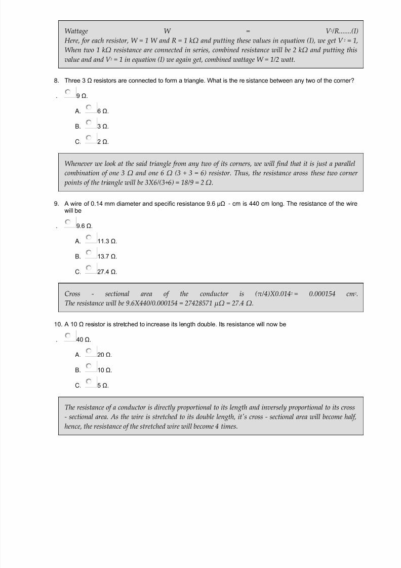
8. Three 3 Ω resistors are connected to form a triangle. What is the resistance between any two of the corner?
. 9 Ω.
A. 6 Ω.
B. 3 Ω.
C. 2 Ω.
Whenever we look at the said triangle from any two of its corners, we will find that it is just a parallelcombination of one 3 Ω and one 6 Ω (3 + 3 = 6) resistor. Thus, the resistance aross these two corner points of the triangle will be 3X6/(3+6) = 18/9 = 2 Ω.
9. A wire of 0.14 mm diameter and specific resistance 9.6 μΩ - cm is 440 cm long. The resistance of the wirewill be
. 9.6 Ω.
A. 11.3 Ω.
B. 13.7 Ω.
C. 27.4 Ω.
Cross - sectional area of the conductor is (π/4)X0.0142 = 0.000154 cm2
The resistance will be 9.6X440/0.000154 = 27428571 μΩ = 27.4 Ω.
10. A 10 Ω resistor is stretched to increase its length double. Its resistance will now be
. 40 Ω.
A.
20 Ω.
B. 10 Ω.
C. 5 Ω.
The resistance of a conductor is directly proportional to its length and inversely proportional to its cross- sectional area. As the wire is stretched to its double length, it's cross - sectional area will become half,hence, the resistance of the stretched wire will become 4 times.

7/21/2019 Objective Questions Electrical Engineering.pdf
http://slidepdf.com/reader/full/objective-questions-electrical-engineeringpdf 17/150
11. Specific resistance is measured in
. mho.
A. ohm.
B. ohm - cm.
C.
ohm/cm.
The resistance R = ρl/a where R is the resistance of any substance in ohm, ρ is the specific resistance ofmaterial of that substance, l and a are length in cm and cross - sectional area in cm2 of that substancerespectively. Therefore, ρ = R.a/l and its unit may be ohm X cm2/cm or ohm – cm.
12. A wire of resistance R has it length and cross - section both doubled. Its resistance will become
0.5R.
A.
R.
B. 2R.
C. 4R.
The resistance of a conductor is directly proportional to its length and inversely proportional to its cross- sectional area. As the length and cross - sectional area both have become double, there will no change inresistance of the wire.
13.
A cube of material of side 1 cm has a resistance of 0.002 Ω between its opposite faces. If the same volumeof the material has a length of 4 cm and a uniform cross - section, the resistance of this length will be
0.128 Ω.
A. 0.064 Ω.
B. 0.032 Ω.
C. 0.016 Ω.
Here, the cube of material of side 1 cm has a resistance of 0.002 Ω between its opposite faces that meansthe resistivity of the material is 0.002 Ω. Now the length of the material has become 4 cm, hence forsame volume 1 cm3 the cross - sectional area of the material will be 1/4 or 0.25 cm2. The new resistancewill be 0.002X4/0.25 = 0.032 Ω.
14. Resistance of which material does not change with change in temperature ?
Platinum.
A. Metal alloys constantan and manganin.

7/21/2019 Objective Questions Electrical Engineering.pdf
http://slidepdf.com/reader/full/objective-questions-electrical-engineeringpdf 18/150
B. Brass.
C. Tungsten.
Resistance is constant with changes in temperature in the metal alloy of constantan and manganin. Thismaterial has the temperature coefficient zero. They can be used for precision wire wound resistors, which
do not change resistance when the temperature increased.
15. The hot resistance of a tungsten lamp is about 10 times the cold resistance. Accordingly, cold resistance oa 100W, 200V lamp will be
400 Ω.
A. 40 Ω.
B. 4 Ω.
C.
800 Ω.
Where, V is supply voltage and W is wattage rating of the lamp. Here, V = 200 V and W = 100 W,
∴ cold resistance of the lamp is 400 ⁄ 10 = 40 Ω
16.
For same voltage, the ratio resistance of 100 W lamp to resistance of 25 W lamp is 16.
A. 4.
B. 1/4.
C. 1.
Where, V is supply voltage and W is wattage rating of the lampFrom, above equation it is clear that, for fixed voltage source, resistance of an electric lamp is inversely proportional to its wattage rating. That means, ratio of resistance will be just reverse of their ratio ofwattage rating.
17. Which of the following has least resistivity?
Copper.

7/21/2019 Objective Questions Electrical Engineering.pdf
http://slidepdf.com/reader/full/objective-questions-electrical-engineeringpdf 19/150
A. Lead.
B. Mercury.
C. Aluminium.
MATERIALSRESISTIVITY AT20 °C
Copper
1.68 X 10-
8 Ω - m Lead
22 X 10-
8 Ω - m Mercury
98 X 10 -
8Ω - m Aluminium
2.65 X
10 - 8 Ω - m
18. Which of the following lamp has least resistance ?
200 W, 220 V.
A. 100 W, 220 V.
B. 60 W, 220 V.
C.
25 W, 220 V.
Where, V is supply voltage and W is wattage rating of the lampFrom, above equation it is clear that, for fixed voltage source, resistance of an electric lamp is inversely proportional to its wattage ratingHere, 200W, 220V lamp has highest wattage rating, therefore its resistance will be least.
19.
200 resistors of 200 Ω each are connected in parallel. Their equivalent resistance will be
1 Ω.
A. 200 Omega;.
B. 400 Omega;.
C. 4 kΩ.
If N numbers of resistors of RΩ each are connected in parallel. Their equivalent resistance will be R ⁄ N.
20. The resistance of 100W, 200V lamp is
200 Ω.
A. 400 Ω.
B. 800 Ω.
C. 1600 Ω.

7/21/2019 Objective Questions Electrical Engineering.pdf
http://slidepdf.com/reader/full/objective-questions-electrical-engineeringpdf 20/150
Where, V is supply voltage and W is wattage rating of the lampHere, wattage of the lamp W = 100W, and supply voltage V = 200V
Multiple Choice Questions on Electrical Resistance |Page – 2
Old pagination
1. A 1 kΩ, 1 W resistor can safely pass a current of
A.
30 mA.
B.
60 mA.
C. 40 mA.
D.
100 mA.
The wattage rating of the resistor W = I 2.RHere W = 1 W, R = 1 kΩ = 1000 Ω∴ I = √(1/1000) = 0.0316 A = 31.6 mA > 30 mA.
2.
Two resistors are connected in parallel across a battery of 2 V and a current flow through the combine resistors is 2 AIt one of the resistors is disconnected, the current will become 1.5 A, then what will be the resistance of that
disconnected resistors?
. 2 Ω.
A. 4 Ω.
B. 1 Ω.
C.
0.5 Ω.
Total current is 2A and after disconnection of one, resistors, the current drawn from the battery, is1.5A. That means the disconnected resistors was sharing 0.5A of currents. So resistance of thedisconnected resistor will be 2/0.5 = 4 ohm.
3. Parallel combination of three 3 ohm resistors, connected in series with parallel combination of two 2 ohm resistors,
what will be the equivalent resistance of overall combination ?
. 2 Ω.
7/21/2019 Objective Questions Electrical Engineering.pdf
http://slidepdf.com/reader/full/objective-questions-electrical-engineeringpdf 21/150
A. 3 Ω.
B. 5 Ω.
C.
1 Ω.
Three 3 ohm resistor are connected in parallel equivalent resistance will be 3/3=1ohmTwo 2 ohm resistor are connected in parallel equivalent resistance will be 2/2=1ohmSo, total resistance when these two combinations are series connected, the total resistance will be 1 + 1 =2 ohm.
4. When a numbers of different valued resistance are connected in series, the voltage drop across each of the resistor is
.
proportional to resistance.
A. proportional to current.
B.
proportional to square of current.
C. equal.
Let V is the source voltage and R1 , R2 , R3 ,........Rn resistances are connected in series, across the source ofvoltage V. Therefore, the current through the resistances will be ........... Therefore, V 1 = IR1 , V 2 = IR2 , V 3 =IR3.........V n = IRn. That means V n ∝ RSo, voltage drop across each resistance will be proportional to their resistive values.
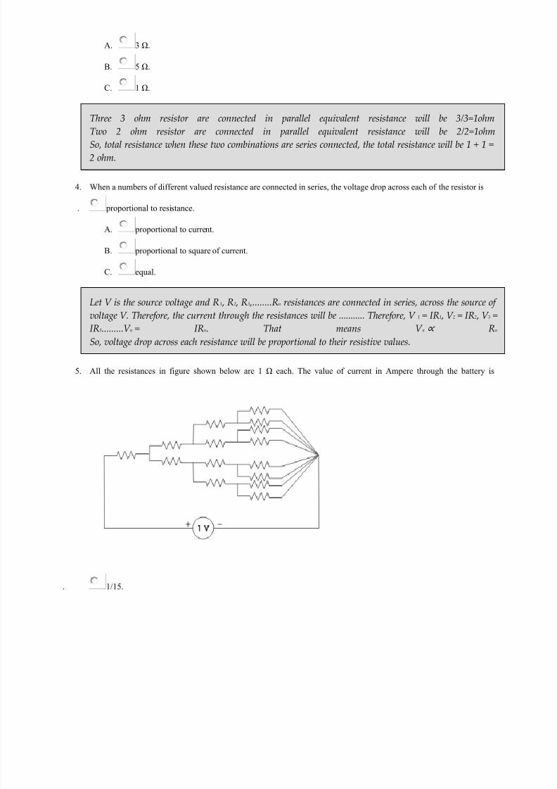
5.
All the resistances in figure shown below are 1 Ω each. The value of current in Ampere through the battery is
.
1/15.

7/21/2019 Objective Questions Electrical Engineering.pdf
http://slidepdf.com/reader/full/objective-questions-electrical-engineeringpdf 22/150
A. 2/15.
B. 4/15.
C.
8/15.
If look at thecircuit from right side, we will see that the equivalent resistance of the circuit is 15 / 4 Ω. Currentthrough the battery will be 1 V / (15 / 4) Ω = 4 /15 A.
6.
Two wires A and B of same material and length l and 2l have radius r and 2r respectively. The ratio of their specificresistance will be
. 1 : 4.
A. 1 : 2.
B. 1 : 1.
C. 1 : 8.
The resistivity of any substance depends upon its material not upon its dimensions.
7. If the length of a wire of resistance R is uniformly stretched n times its original value, its new resistance is
.
n.R.
A. n2.R.
B. R/n.
7/21/2019 Objective Questions Electrical Engineering.pdf
http://slidepdf.com/reader/full/objective-questions-electrical-engineeringpdf 23/150
C. R/n2.
Let's cross-section of the wire is A = πr2 , length of the wire is l therefore volume of the wire is A.l. Nowif the length of the wire is stretched to n times of its original length i.e. now length of the wire becomes l'= n.l. Now if r' is the new radius of the cross-section of the wire then new cross-sectional area A' = πr'2
If the volume of the wire is same before and after stretching, A.l = A'.l' ⇒ πr'2.n.l = πr2.l ⇒ r'2 = r2/n ⇒
πr'2 = πr2/n ⇒ A' = A/n. Thus resistance of the wire after stretched is ρ(l'/A')= ρn.l/(A/n) = n2ρ(l/A) =n2.R.
8. The resistance between the opposite faces of 1 m cube is found to be 1 Ω. If its length is increased to 2 m, with itsvolume remaining the same, then its resistance between the opposite faces along its length is
. 1 Ω.
A. 2 Ω.
B.
4 Ω.
C.
8 Ω.
Volume = lengthXarea so if length is increased by 2 times then area will be decreased by 1/2, if resistanceR = ρ(l/A) = 1 Ω ⇒ R' = ρ(2l/0.5A) = 4ρ(l/A) = 4R = 4 Ω.
9. A wire of length l and of circular cross - section of radius r has a resistance of R ohms. Another wire of same materialand of x-section radius 2r will have the same R if the length is
.
2l.
A.
l/2.
B. l2.
C. 4l.
The cross-section of the first wire is πr2. The cross-section of the second wire is π(2r)2 = 4πr2. Theresistance of any wire depends upon the ratio of its length to area. So if the cross-section of the second
wire is 4 times of that of first wire, the length of the second wire must also be 4 times of that of first if theresistance of both wires are same.
10. The insulation resistance of a cable of 10 km is 1 MΩ. For a length of 100 km of the same cable, the insulationresistance will be
. 1 MΩ.
A. 0.1 MΩ.
B. 10 MΩ.

7/21/2019 Objective Questions Electrical Engineering.pdf
http://slidepdf.com/reader/full/objective-questions-electrical-engineeringpdf 24/150
C. 0.01 MΩ.
Conductor resistance is directly proportional to length. But insulation resistance is the resistance to the flow of leakage current to ground. Since the flow of leakage current is directly proportional to the lengthof the conductor as because with length conductor inner and outer surface are of the insulation layer ofthe conductor increases. So insulation resistance is inversely proportional to the length of conductor.
11. The hot resistance of the filament of a bulb is higher than the cold resistance because the temperature coefficient of the
filament is >
. positive.
A. negative.
B. zero.
C. infinite.
Positive temperature coefficient refers to materials that experience an increase in electrical resistancewhen their temperature is raised.
12. The temperature coefficient of resistance of an insulator is
positive and independent of temperature.
A.
negative and dependent on temperature.
B.
negative and independent on temperature.
C. positive and dependent on temperature.
.
13. Four resistances 80 Ω, 50 Ω, 25 Ω and R are connected in parallel. Current through 25 Ω resistance is 4 A. Totalcurrent of the supply is 10 A. The value of R will be
36.36 Ω.
A. 66.66 Ω.
B.
40.25 Ω.
C. 76.56 Ω.

7/21/2019 Objective Questions Electrical Engineering.pdf
http://slidepdf.com/reader/full/objective-questions-electrical-engineeringpdf 25/150
The currentthrough 25 Ω resistor is 4 A hence voltage across it is 4X25 = 100 V and this is the voltage across thesupply as well as other resistors. hence current through 50 Ω and 80 Ω resistors will be 100/50 = 2Aand 100/8 = 1.25 A. Therefore current through R x will be 10 - 4 - 2 - 1.25 = 2.75 A and then Rx =100/2.75 = 36.36 Ω
14. Three parallel resistive branches are connected across a DC supply. What will be the ratio of the branch current
I1:I1:I1 if the branch resistances are in the ratio R 1:R 2:R 3 :: 2:4:6
6:4:2.
A. 6:3:2.
B. 2:4:6.
C.
3:2:6.
Current is inversely proportional to resistance. Then 1/2:1/4:1/6=3:3/2:1=6:3:2.
15.
Two resistors R 1 and R 2 given combined resistance of 4.5 Ω when in series and 1 Ω when in parallel, the resistance are
1.5 Ω and 3 Ω.
A. 2 Ω and 2.5 Ω.
B. 1 Ω and 3.5 Ω.
C. 4 Ω and 0.5 Ω.

7/21/2019 Objective Questions Electrical Engineering.pdf
http://slidepdf.com/reader/full/objective-questions-electrical-engineeringpdf 26/150
When in seriesR1 + R2 = 4.5...........(1)when in paralle(R1*R2)/(R1 + R2) = 1(R1*R2)/4.5 = 1R1*R2 = 4.5..........(2)
COMBINING (1) AND (2),WE GETR1 = 1.5 or 3 and R2 = 3 or 1.5
16.
When a resistor R is connected to a current source, it consumes a power of 18 W. When the same R is connected to a
voltage source having the same magnitude as the current source, the power absorbed by R is 4.5 W. The magnitude of
the current source and the value of R are
√18 A and 1 Ω.
A. 1 A and 18 Ω.
B.
3 A and 2 Ω.
C. 6 A and 0.5 Ω.
For resistance R, connected to the current source, the consumed power is 18w i.e 18 = I 2R (1) and forsecond condition 4.5 = V 2/R (2) and current and voltage having same magnitude that is V = I (3).By solving these 3 equations we get R = 2 ohms and I = 3 A
17. When all the resistances in the circuit are of 1 Ω each, the equivalent resistance across the points A and B will be
. 1 Ω.
A. 0.5 Ω.
B.
1.5 Ω.
7/21/2019 Objective Questions Electrical Engineering.pdf
http://slidepdf.com/reader/full/objective-questions-electrical-engineeringpdf 27/150
C. 2 Ω.
All the resistances are same. There is no potential difference between central vertical resistance [likeWheatstone Bridge], so it can be imagined that it is opened. Then the equivalent resistance between A &B is Req = (1+1) || (1+1) || 1 ΩReq = 2 || 2 || 1 ΩReq = 0.5 Ω
18. Resistivity of metals is expressed in terms of
μ Ω.
A. μ Ω - cm ⁄ °C.
B. μ Ω - cm.
C. μ Ω.
The
resistivity ρ = R.A
L The resistivity also changes with temperature so for expressing resistivity one should
mentioned temperature too. Hence, the most appropriate unit of resistivity is μ Ω - cm ⁄ °C.
Resistivity of copper is of the order of
. 17.2 μ ohm-cm.
E. 1.72 μ ohm-cm.
F.
0.172 μ ohm-cm.
G. 172 μ ohm-cm.
Multiple Choice Questions of Analog Electronics
1.
The conduction loss verses device current characteristics of power MOSFET in best approximately by
A. a parabola.
B. an exponentially decaying function.
C. a rectangular hyperbola.
D. a straight line.

7/21/2019 Objective Questions Electrical Engineering.pdf
http://slidepdf.com/reader/full/objective-questions-electrical-engineeringpdf 28/150
I = Device current, Ron = on state Resistance of Power Mosfet, hence conduction loss P = I 2Ron. Thereforeconduction loss verses device current characteristics can be approximately parabola.
2. A 3phase diode bridge rectifier is fed from a 400V R.M.S, 50 Hz, 3 phase AC source. If the load is purelyresistive, then peak instantaneous output voltage is equal to
. 400√2 V.
A. 400 V.
B. 400√(2/3) V.
C. 400/√3 V.
As the load is resistive the peak instantaneous output voltage V m = 400√2 V.
3. An SCR is considered to be a semi controlled device because-
. it can be turned OFF but not On with a gate pulse.
A. it conducts only during one half cycle of an alternating current wave.
B. it can be turned ON but not OFF with a gate pulse.
C. it can be turned ON only during one half cycle of an AC.
During positive half cycle SCR is in forward Blocking mode. By applying gate pulse the SCR can be
turned ON during forward Blocking mode. But SCR can be turned OFF by applying gate pulse. That iswhy it is called semi controlled rectifier.
4. Dual slope ADC has R = 1 KΩ & C = 0.22 nanofarad has charging & discharge times for some voltage is 9ns & 3 ns respectively. The reference Voltage is 2.2 V. What is the peak voltage reached by triangular waveduring charging?
. 90 mV.
A. 30 mV.
B.
300 mV.
C. 900 mV.
V x = (V in*T dis) ⁄ (Rc) = (V ref T dis)⁄ Rc = (2.2*3*10-9) ⁄ (2.210 − 7) = 30 mV

7/21/2019 Objective Questions Electrical Engineering.pdf
http://slidepdf.com/reader/full/objective-questions-electrical-engineeringpdf 29/150
5. An SCR has half cycle surge current rating of 3000A for 50 Hz supply. One cycle surge current will be
. 1500 A.
A. 6000 A.
B. 2121.32 A.
C.
4242.64 A.
6. The typical value of SCR for modern alternator is-
. 1.5.
A. 0.5.
B.
1.0.
C. 1.2.
Always the typical value of SCR for modern alternator is 0.5.
7. A zener diode voltage regulator has load requirement of 12 V & 2 Amp. The zener diode's minimum currentrequirement is 0.2 A. The minimum voltage at input is 24 V. What is Maximum efficiency of circuit?
. 34.3%.
A. 45.5%.
B. 52.8%.
C. 66.3%.
η = (212) ⁄ (2.224)100 % = 24 ⁄ 52.8 = 45.5 %
8. In n type semiconductor elements of which group of periodic table is added as dopant
. group 5.
A. group 2.
B. group 3.
C. group 4.

7/21/2019 Objective Questions Electrical Engineering.pdf
http://slidepdf.com/reader/full/objective-questions-electrical-engineeringpdf 30/150
With group 5 elements like phosphorous, arsenic, antimony are added to Ge or Si crystal which produces free electrons.
9. Darlington connection is achieved in 2 transistors by connecting
. both emitter.
A.
both collector.
B. both base.
C. grounding both collector.
in darlington connection 2 transistor's collectors are connected and emitter of 1st transistor to the baseof 2nd is also connected. This provides a three terminal device that in actual operation can be regarded as2 cascaded emitter followers.
10. FM stands for
. frequent modulation.
A. frequency modulation.
B. frequency moderator.
C. frequent moderator.
n telecommunications and signal processing, frequency modulation (FM) conveys information over acarrier wave by varying its instantaneous frequency. This contrasts with amplitude modulation, inwhich the amplitude of the carrier is varied while its frequency remains constant.
11. An opamp comparator circuit employs
no feedback.
A. +ve feedback.
B.
-ve feedback.
C. both b and c.
comparator is a device used for comparison of 2 voltage levels. Output indicates which of the 2 voltagesis greater.No feedback is used.
12. A single phase full wave midpoint thyristor uses a 230/200 V Transformer with central tap on the secondaryside. The PIV per thyristor is-

7/21/2019 Objective Questions Electrical Engineering.pdf
http://slidepdf.com/reader/full/objective-questions-electrical-engineeringpdf 31/150
282.8 V.
A. 200 V.
B. 100 V.
C. 141.4 V.
PIV=√(2)V m = √(2)200 = 282.84 V.
13. In a rectifier circuit, the diode converts
alternating voltage to direct voltage.
A. both (A)&(C) options are connect.
B. alternating voltage to direct current.
C. alternating current to direct voltage.
Diode converts alternatring voltage to unidirectional current which is then converted in to voltage byload resistance connected across the output node.
14. A single phase one pulse controlled circuit has a resistance & counter emf load &400 sin(314t) as the sourcevoltage for a load counter emf of 200 V, the range of firing angle control is-
30 degree to 150 degree.
A. 30 degree to 180 degree.
B. 60 degree to 120 degree.
C. 60 degree to 180 degree.
400 sinθ=200 or, θ=30 degree, so control range is &theta to(Ï€ -θ) i.e. 30 degree tp 150 degree.
15. A single phase full bridge inverter can operated in load commutation mode in case load consist of-
RL.
A. RLC underdamped.
B. RLC overdamped.
C. RLC critically damped.
7/21/2019 Objective Questions Electrical Engineering.pdf
http://slidepdf.com/reader/full/objective-questions-electrical-engineeringpdf 32/150
In this case reading current will flow in circuit & it will became zero so thyristor will be loadcommutated.
16. A junction transistor with β=49 & Ic0 = IcB0 = 1µA has IB=10µA .The value of Ic is given in µA by-
540.
A.
440.
B. 539.
C. 490.
Ic=βIB+(β+1)*Ic0=49*10+50*1=540µA.
17. A step up chopper has input voltage 110 V & output voltage 150 V .The vqalue of duty cycle is-
0.32.
A. 0.67.
B. 0.45.
C. none of these.
150=110(1⁄1-α) or, 150 -150α=110 or, α=40⁄150=0.267(α-duty cycle).
18.
A schottky diode is a-
majority carrier device.
A. minority carrier device.
B. fast recovery diode.
C. both a majority & a minority carrier diode.
Although a schottky diode behaves a p-n junction diode, there is no physical junction and as a result aschottky diode is a majority carrier diode.
Objective Questions on Battery 1. Primary battery is such a battery

7/21/2019 Objective Questions Electrical Engineering.pdf
http://slidepdf.com/reader/full/objective-questions-electrical-engineeringpdf 33/150
A. which can be recharged.
B. which cannot be reconditioned by replacing chemical.
C. which cannot be reused.
D. which cannot be recharged.
An electro-chemical cell or battery is such which can not be recharged but the chemical has to be replaced for reconditioning, is called primary battery.
2. The first electro - chemical cell was invented by
. Luigiri Galvani.
A. Alessandro Volta.
B.
Deniel.
C. Lechanche.
The first electrochemical cell was invented by Luigiri Galvani in 1791. It was greatly improved by Alessandro Volta in the year of 1800.
3. The secondary battery is such a battery
. which cannot be recharged.
A. which can be recharged.
B. which can be reused after replacing its chemical.
C. which is charged by primary cells.
A secondary battery cell is one in which chemical energy is converted into electrical energy but they doonly when they are charged by passing current through them by some source.
4.
An example of secondary battery cell is
. Edison Alkali cell.
A. Daniel cell.
B. Lachanche cell.
C. Bunsen cell.

7/21/2019 Objective Questions Electrical Engineering.pdf
http://slidepdf.com/reader/full/objective-questions-electrical-engineeringpdf 34/150
Voltiac cell, daniel cell, Lachanche cell, Bunsen cell, fuel cell are some well known example of primarybattery cells. Whereas, Lead Acid cell and Edison Alkali cell are two well known example of secondarycells.
5. Internal resistance of a battery cell increases with
.
increases in concentration of electrolyte.
A. increase in distance between two electrodes.
B. increases in area of the plates inside the electrolyte.
C. increase in size of the electrodes.
Internal resistance of a battery cell1. increases with increase in distance between two electrodes,2. decreases with increase in concentration of electrolyte,3. decreases with increase in area of the plates inside the electrolyte4. decreases with increase in size of the electrodes.
6. Internal resistance of a battery cell decreases with
. increase in area of the plates inside the electrolyte.
A. increase in distance between two electrodes.
B. decrease in size of the electrodes.
C. increase of age of the battery.
Internal resistance of a battery cell1. increases with increase in distance between two electrodes,2. decreases with increase in concentration of electrolyte,3. decreases with increase in area of the plates inside the electrolyte4. decreases with increase in size of the electrodes.
7.
Unit of electro - chemical equivalent of the substance of electrolyte
. Kg - Coulomb.
A. Kg / Coulomb.
B. Coulomb / Kg.
C. Kg / °C.

7/21/2019 Objective Questions Electrical Engineering.pdf
http://slidepdf.com/reader/full/objective-questions-electrical-engineeringpdf 35/150
According to Faraday's law of electrolysis,the mass (Δm) of ions liberated at an electrode is directly proportional to the quantity of charge (Δq) passing through the electrolyteΔm ∝ Δq ⇒ Δm = Z.Δq ⇒ Z = Δm ⁄ ΔqThis Z is proportionality constant and also called Electro - Chemical Equivalent of the substance of theelectrolyte.From the above relation it is clear that unit of Z may be Kg/Coulomb *unit of mass ⁄ unit of charge.
8. If Z is the electro - chemical equivalent of a substance of the electrolyte. E is the chemical equivalent of thesame substance, then the relation between Z & E will be,
. Z &porp; E.
A. Z = E.
B. Z < E.
C. Z > E.
Faraday's second law of electrolysis states Electro - Chemical Equivalent of a substance is directly proportional to its chemical equivalent.
9. Negative electrode or anode of simple voltaic cell is made of
. copper.
A. zinc.
B.
lead.
C. carbon.
In Voltaic battery cell, zinc atoms in contact with dilute sulfuric acid give up electrons and formsZn++ ions which pass into the electrolyte. As a result zinc electrodes get high concentration of electronsand it get negatively charged. Hence this zinc electrode acts as negative electrode or anode.
10. For all substances, [Chemical Equivalent / Electro - Chemical Equivalent] =
96500 Coulombs.
A. 9650 Coulombs.
B. 965 Coulombs.
C. 96.5 Coulombs.

7/21/2019 Objective Questions Electrical Engineering.pdf
http://slidepdf.com/reader/full/objective-questions-electrical-engineeringpdf 36/150
Faraday's second law of electrolysis states Electro - Chemical Equivalent ( Z ) of a substance is directly proportional to its chemical equivalent ( E ).∴ Z ∝ E ⇒ E ⁄ Z = F, a constant called Faraday's constantand value of F = 96500 Coulomb.
11. A 10V battery with an internal resistance of 1 Ω is connected across a non-linear load whose v-characteristic is given by 7i = v2 + 2v. The current delivered by the battery is
7 A.
A. 6 A.
B. 5 A.
C. 4 A.
.
12. Nickel is used in
electrodes of thermionic valves.
A. bulb filaments.
B. automatic voltage regulators.
C. pressure sensitive elements.
The electrodes of a thermionic valve are generally made of nickel.
13. A cell has an Ah efficiency of 80%. It has an average terminal voltage on discharge and charge of 1.2 V and1.6 V respectively. The Watt- hour efficiency of the cell is ............... %.
60%.
A. 80 %.
B. 100%.
C.
50%.
14. Effect of temperature on internal resistance of a battery is
directly proportional.
A. inversely proportional.

7/21/2019 Objective Questions Electrical Engineering.pdf
http://slidepdf.com/reader/full/objective-questions-electrical-engineeringpdf 37/150
B. no effect.
C. none of these.
Internal resistance Ri is inversely proportional to temperature t.
15.
E.C.E stands for
electrovalent chemical equivalent.
A. electron chemical equivalent.
B. electro chemical equivalent.
C. electrolysis cathode equivalent.
E.C.E stands for ELECTRO CHEMICAL EQUIVALENT. E.C.E is the mass of ions in grams which isliberated /deposited by chemical action by the passage of 1C of electricity i.e 1A for 1 sec.
Objective Questions on Capacitor 1. A capacitor
A. passes ac but blocks dc.
B. passes dc but blocks ac.
C. passes both ac and dc.
D. blocks both ac and dc.
The impedance of capacitor can be expressed as
.Hence, impedance of capacitor is inversely proportional to the supply frequency(f). In ac frequency hasnon - zero finite value, so impedance will have finite value but in DC f = 0, so impedance will have
infinitely large value. Thus a capacitor blocks DC but passes AC.
2. A 100 μF capacitor supplied from 3 V source with a frequency of 50 Hz. The capacitive reactance is
. 63.68 Ω.
A. 15.92 Ω.
B. 31.84 Ω.

7/21/2019 Objective Questions Electrical Engineering.pdf
http://slidepdf.com/reader/full/objective-questions-electrical-engineeringpdf 38/150
C. 7.96 Ω.
The capacitive reactance can be expressed as
3.
A capacitor passes a current of 12.6 mA when supplied with 20 V ac with a frequency of 1000 Hz. Thecapacitance will be
. 0.001 μF.
A. 0.01 μF.
B. 0.1 μF.
C. 1 μF.
Where, V c is the voltage across capacitor, I c current through the capacitor, f & C are frequency andcapacitance.Here, V c = 20 V, I c = 12.6 mA and f = 1000 Hz
4. A 10 μF capacitor and 100 W, 220 V lamp is connected in series across a 220 V alternating supply. In whichfrequency of the supply the lamp will glow brightest?
. 1000 Hz.
A. 100 Hz.
B. 10 Hz.
C. 1 Hz.
The impedance of capacitor is inversely proportional to its supply frequency. The impedance offered bythe capacitor to the circuit is less when supply frequency is more. If impedance is less, current flowsthrough the circuit (i.e. lamp) is more which results to glow the lamp brighter.
5. A 20 μF capacitor and 200 W, 220 V lamp is connected in series across a 220 V alternating supply. In whichfrequency of the supply the lamp will glow dimmest?
. 1000 Hz.
7/21/2019 Objective Questions Electrical Engineering.pdf
http://slidepdf.com/reader/full/objective-questions-electrical-engineeringpdf 39/150
A. 1 Hz.
B. 10 Hz.
C. 100 Hz.
The impedance of capacitor is inversely proportional to its supply frequency. The impedance offered bythe capacitor to the circuit is more when supply frequency is less. If impedance is more, current flowsthrough the circuit (i.e. lamp) is less which results to glow the lamp dimmer.
6. The capacitive reactance of a capacitor of 1 / 2π F at 10 3 Hz is
. 10 6 Ω.
A. 10- 3 Ω.
B. 10 3 Ω.
C. 10- 6 Ω .
The capacitive reactance can be expressed as
7. When ac flows through a pure capacitance then the current
. leads the emf by 90°.
A. lags the emf by 90°.
B. leads the emf by - 90°.
C. is in phase with emf.
When ac flows through an capacitance, the current leads the emf by 900.
8. It a capacitors of capacitance 100 μF is connected across a voltage source of 10 V, then what will be the
energy stored in that capacitor
. 5 × 10 - 3 Joule.
A. 10 × 10 - 3 Joule.
B. 10 × 10 6 Joule.
C. 5 × 10 - 2 Joule.

7/21/2019 Objective Questions Electrical Engineering.pdf
http://slidepdf.com/reader/full/objective-questions-electrical-engineeringpdf 40/150
It a capacitor of capacitance value C have voltage difference V between its parallel plates then the energystored in the capacitor is expressed as
9. A capacitor carries a charge of 0.3 C at 20 V. Its capacitance is
.
1.5 F.
A. 0.015 F.
B. 1.5 μF.
C. 15 μF.
The capacitance of a capacitor is expressed as
Where C is the capacitance, Q is charge & V is the voltage.
10. A parallel plate capacitor has a capacitance of C farad. It area of the plates is doubled and the distancebetween them is half, the capacitance of the capacitor is
. 1 C farad.
A. 2 C farad.
B. 4 C farad.
C. 16 C farad.
A capacitor consists of two parallel places separated by a dielectric material. It the area of the plates is Am2 and the distance between them is d meter, the capacitance C is given by
Where A is the area of the plates & d is distance between the plates. From the above expression ofcapacitance it is obvious that, if area is doubled and distance is half the capacitance will become 4 times.
11.
Which of the followings is the expression for energy stored in a capacitor
. Cv.
A. C dv/dt.
B. C/v.
C. (1/2)Cv2.

7/21/2019 Objective Questions Electrical Engineering.pdf
http://slidepdf.com/reader/full/objective-questions-electrical-engineeringpdf 41/150
The instantaneous power in the capacitor is given by p=iv
12. A capacitor is connected to supply with switch and the switch is connected between capacitor and supply.
Initially switch is open at time zero, and then switch is closed. Then how capacitor behaves at time t=0+
short circuit.
A. open circuit.
B. dielectric losses decreases.
C. dielectric losses increases.
In case of a capacitor voltage across it does not change instantaneously. If an uncharged capacitor isconnected to an energy source, at the time of switching, the capacitor will behave like a short circuit.
13. C eq of two capacitors connected in series is given by
C1 C2.
A. C1 =C2.
B. C1 C2 /C1 +C2.
C.
C1 +C2.
SERIES combination of capacitors is same as PARALLEL of resistance.
14. A capacitor has a capacitance of 6 μF. Calculate the stored energy in it if a dc voltage of 100 V, is appliedacross it
3 × 10 − 2 joules.
A. 2.5 × 10 − 2 joules.
B. 6 × 10 − 2 joules.
C. 4 × 10 − 2 joules.
15. A capacitor that stores charge of 0.5 C at 10 V has a capacitance of ................ farad.

7/21/2019 Objective Questions Electrical Engineering.pdf
http://slidepdf.com/reader/full/objective-questions-electrical-engineeringpdf 42/150
5.
A. 0.05.
B. 10.
C. 20.
16. A p.d. of 300 V is applied across series combination of 3 μF and 9 μF capacitors. The charge on eachcapacitor is ...................... μC.
675.
A. 3600.
B.
240.
C. 7.5.
17.
A 50 μF capacitor is charged to retain 10 MJ of energy by a constant charging current of 1 A. Determine thevoltages across the capacitor:-
30 V.
A. 20 V.
B. 50 V.
C. 60 V.
V being the voltage developed across the capacitor of capacitance(C)
18. The capacitance of a conductor is varying from 2 microfarad to zero in 1 sec linearly if the voltage applied toit is 6 V the energy stored in 0.5 sec in the condenser is
55.1μ joules.

7/21/2019 Objective Questions Electrical Engineering.pdf
http://slidepdf.com/reader/full/objective-questions-electrical-engineeringpdf 43/150
A. 18 μ joules.
B. 10μ joules.
C. 20μ joules.
Here C is taken as μ F only since capacitor varies linearly.
19. What will be the capacitance when distance between the 2 plates of a condenser of capacitance 8 microfarad is reduced from 10 mm to 4 mm?
20 microfarad.
A. 3.2 microfarad.
B. 8 microfarad.
C. 1 microfarad.
Where, A is common area of conductor plates
Where, d is the distance between two conductor plates.
20.
Purpose of using capacitor is/are
increase p.f of inductive load circuit.
A. to do phase split in ac 1 phase motor.
B. effect dc filter in electronic circuit.
C. all of these.
Purposes of using capacitors are
1) increasing p.f. of inductive load circuit2) to do phase split in ac 1 phase motor3) effect dc filter in electronic circuit4) also helps in tuning in radio and TV sets.
Objective Questions on Circuit Theory | Page – 1
1. If E1 = A.sinΩt & E2 = A.sin(Ωt - θ), then

7/21/2019 Objective Questions Electrical Engineering.pdf
http://slidepdf.com/reader/full/objective-questions-electrical-engineeringpdf 44/150
A. E1 lags E2 by θ ⁄ 2.
B. E1 leads E2 by θ.
C.
E2 leads E1 by θ.
D. E2 leads E1 by θ.
At Ωt = 0, E1 = 0 & E2 = A.sin(-θ) = - A.sinθFrom, the expression of E1 = A.sinΩt & E2 = A.sin(Ωt - θ), it is clear that, E2 crosses zero t = θ ⁄ Ω secafter that of ETherefore, it can be concluded that E1 leads E2 by θ.
2.
) Two sinusoidal quantities are said to be phase quadrature, when their phase difference is
. 0°.
A.
30°.
B. 45°.
C. 90°.
Two sinusoidal quantities are said to be phase quadrature, when their phase difference is 90°.
3. The equation for 25 cycles current sine wave having rms value of 30 amps, will be
.
42.4sin50πt.
A. 30sin50πt.
B.
30sin25πt.
C. 42.4sin25πt.
General equation of sinusoidal current quantity is I msinΩt = I msin2.πf.tWhere, I m is the maximum ampletude of the current wave, f is the frequency or cycle per second
Here, rms value of current is 30A∴ , maximum amplitude of the current wave form I m = √2 X 30 = 42.4 A and frequency f is here 25 HzHence, the current equation will be 42.4sin2.π.25.t = 42.4sin50πt.
4. What will be the rms value of rectangular wave with amplitude 10V
.
5√2 V.
A. 10 V.
7/21/2019 Objective Questions Electrical Engineering.pdf
http://slidepdf.com/reader/full/objective-questions-electrical-engineeringpdf 45/150
B. 11.2 V.
C. 7.7 V.
RMS value means, root mean square value of a wane. A rectangular voltage wave has constantamplitude in both positive and negative direction. Hence the mean value and its amplitude will be
identical. Therefore square root of square of the mean value of amplitude is same as amplitude of thewave.
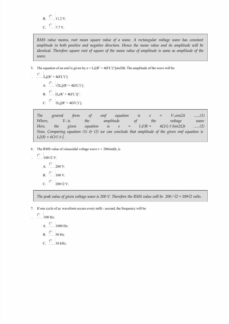
5. The equation of an emf is given by e = Im[(R 2 + 4Ω2L2)½]sin2Ωt. The amplitude of the wave will be
. Im[(R 2 + 4Ω2L2)½].
A.
√2Im[(R 2 + 4Ω2L2)½].
B. [Im(R 2 + 4Ω2L2)]½.
C.
2Im[(R 2 + 4Ω2L2)½].
The general form of emf equation is e = V msinΩt ......(1)Where, V m is the amplitude of the voltage waveHere, the given equation is e = I m[(R2 + 4Ω2L2)½sin2Ωt ......(2)Now, Comparing equation (1) & (2) we can conclude that amplitude of the given emf equation isI m[(R2 + 4Ω2L2)½].
6.
The RMS value of sinusoidal voltage wave v = 200sinΩt, is
. 100√2 V.
A. 200 V.
B.
100 V.
C. 200√2 V.
The peak value of given voltage wave is 200 V. Therefore the RMS value will be 200 ⁄ √2 = 100√2 volts.
7.
If one cycle of ac waveform occurs every milli - second, the frequency will be
. 100 Hz.
A. 1000 Hz.
B.
50 Hz.
C. 10 kHz.

7/21/2019 Objective Questions Electrical Engineering.pdf
http://slidepdf.com/reader/full/objective-questions-electrical-engineeringpdf 46/150
One cycle of ac waveform occurs every milli second means 1000 cycles of that waveform occur in onesecond. The numbers of cycles of waveform per second is the frequency of that waveform.
8. If emf in a given circuit is given by e = 100sin628t, then maximum value of voltage and frequency will be
. 100 V, 100 Hz.
A.
100 V, 50 Hz.
B.
100√2 V, 100 Hz.
C. 50√2 V, 100 Hz.
The emf equation is e = 100sin628t .....(1) Again the general form of emf equation is e = V msin2π.f.t ......(2)Where, V m is the voltage amplitude and f is the frequencyComparing, equations (1) & (2) we getV m = 100 V and 2πf = 628 ⇒ 628/(2X3.24) ⇒ f = 628/6.28 = 100 Hz.
9. The value of supply voltage for 400W, 4 ohm load is
.
40 V.
A. 400 V.
B. 20 V.
C.
200 V.
Where, V is supply voltage and W is wattage rating of the lampHere, W = 400W and R = 4Ω
⇒ V = 40V.
10.
Say A point has an absolute potential of 40V. and point B has an absolute potential of -10V, then what will be the value
of VBA ?
. -50 V.
A.
50 V.
B. 30 V.
C. None of above.
7/21/2019 Objective Questions Electrical Engineering.pdf
http://slidepdf.com/reader/full/objective-questions-electrical-engineeringpdf 47/150
V BA is defined as V B − V A = -10 - 40 = -50V.
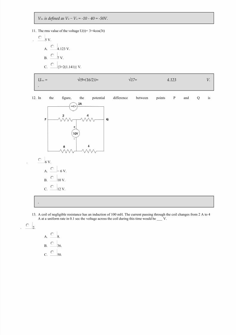
11. The rms value of the voltage U(t)= 3+4cos(3t)
.
5 V.
A. 4.123 V.
B. 7 V.
C. 3+2(1.141) V.
U rms = √(9+(16/2))= √17= 4.123 V.
12. In the figure, the potential difference between points P and Q is
. 6 V.
A. − 6 V.
B. 10 V.
C.
12 V.
.
13.
A coil of negligible resistance has an induction of 100 mH. The current passing through the coil changes from 2 A to 4
A at a uniform rate in 0.1 sec the voltage across the coil during this time would be ___ V.
2.
A. 8.
B. 36.
C.
50.

7/21/2019 Objective Questions Electrical Engineering.pdf
http://slidepdf.com/reader/full/objective-questions-electrical-engineeringpdf 48/150
V = L X di/dt = 100 X 10-3 X 2/0.1 = 2 votls.
14. 1518) What is representated by the hypotenuse of impedance triangle
impedance drop.
A. resistance drop.
B. reactance drop.
C. apparent power .
Impedance triangle means the right angle triangle formed by the vectors representing the resistancedrop, reactance drop & the impedance drop of the circuit carrying an alternating current.
15. The phase angle difference between current and voltage is 90°, the power will be
minimum.
A.
maximum.
B. zero.
C. V.I.
The expression of active power P = V.I.cosθWhere, V is voltage, I is current and θ is the angle between current and voltage
here, this θ = 90°∴ Power P = V.I.cos90° = 0 [Since, cos90°= 0].
16. Kirchhoff's laws are valid for
linear circuit only.
A.
passive time invariant circuits.
B.
non-linear circuits only.
C.
both linear and non-linear circuits.
Linear circuits obey Ohms Law. Kirchhoff's laws are valid for those elements that obey Ohms Law.

7/21/2019 Objective Questions Electrical Engineering.pdf
http://slidepdf.com/reader/full/objective-questions-electrical-engineeringpdf 49/150
17. For the circuit shown below the value of R is adjusted so as to make the current in R Lequal to zero. Calculate the value
of R
. 1 Ω.
A. 2 Ω.
B. 3 Ω.
C.
4 Ω.
As per WheatstoneBridge principle: 10 / 4 = 5 / R ⇒ R = 4 / 10 X 5 ohms ⇒ R = 2 ohms.
18. In the circuit shown in figure if I1 = 1.5A, then I2 will be
.
2 A.
A. 1.5 A.

7/21/2019 Objective Questions Electrical Engineering.pdf
http://slidepdf.com/reader/full/objective-questions-electrical-engineeringpdf 50/150
B. 1 A.
C. 0.5 A.
19. In the circuit shown in the figure the voltage across the 2 Ω resistor is
.
1 V.
A.
2 V.
B. 3 V.
C.
4 V.
20. The value of current I flowing in the 1 Ω resistor in the circuit shown in the given figure will be
. 5 A.
A. 6 A.
B.
0 A.
C. 10 A.
Objective Questions on Circuit Theory | Page – 2
7/21/2019 Objective Questions Electrical Engineering.pdf
http://slidepdf.com/reader/full/objective-questions-electrical-engineeringpdf 51/150
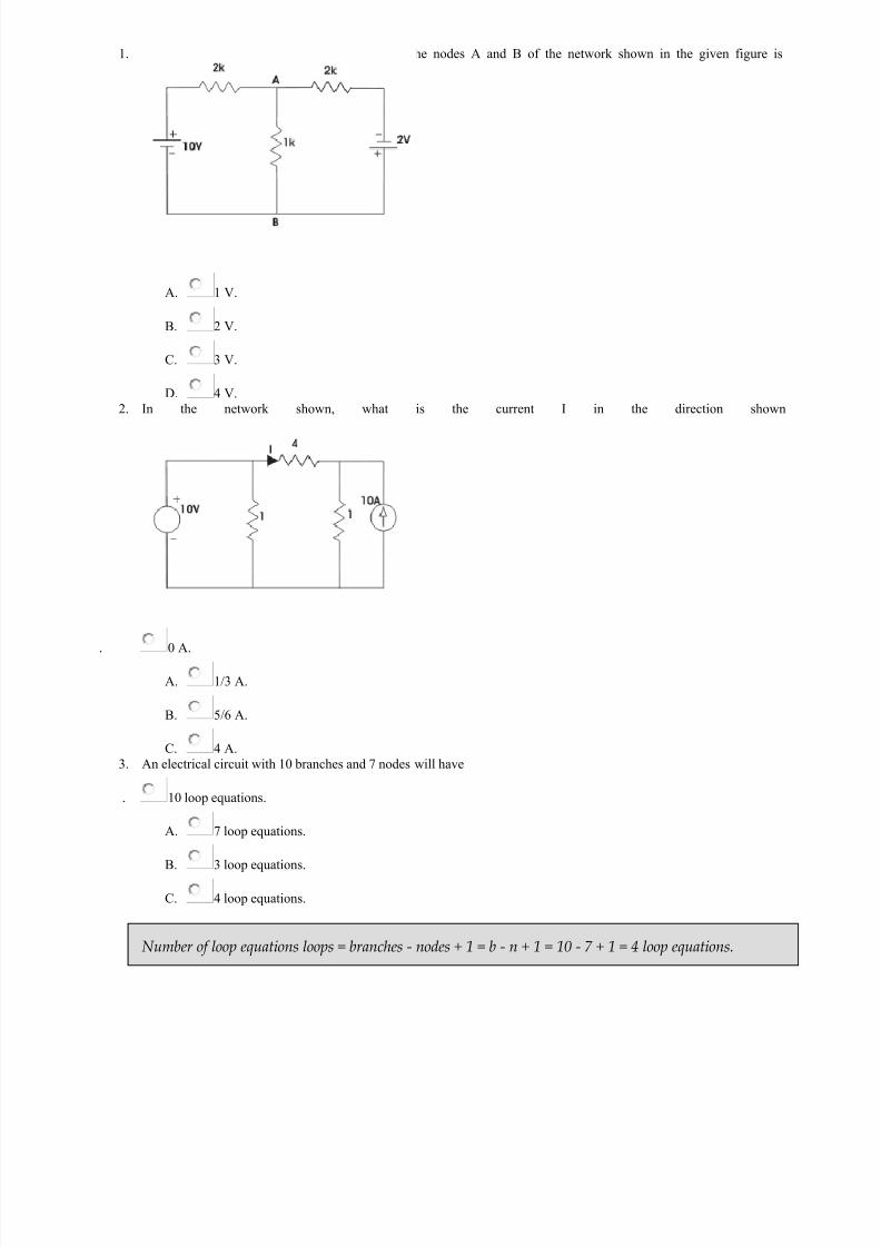
1. The voltage across the 1 kΩ resistor between the nodes A and B of the network shown in the given figure is
A. 1 V.
B. 2 V.
C.
3 V.
D.
4 V.2.
In the network shown, what is the current I in the direction shown
. 0 A.
A. 1/3 A.
B. 5/6 A.
C. 4 A.
3. An electrical circuit with 10 branches and 7 nodes will have
. 10 loop equations.
A.
7 loop equations.
B.
3 loop equations.
C. 4 loop equations.
Number of loop equations loops = branches - nodes + 1 = b - n + 1 = 10 - 7 + 1 = 4 loop equations.

7/21/2019 Objective Questions Electrical Engineering.pdf
http://slidepdf.com/reader/full/objective-questions-electrical-engineeringpdf 52/150
4. In given figure, the value of resistance R in Ω is
.
10.
A. 20.
B. 30.
C. 40.
The given circuit can be simplified by replacing voltage source by equivalent current source as below
The currentthrough 5 Ω resistor is 8 A hence voltage across it is 8X5 = 40 V and this is the voltage across unknownresistor R. As current through R is 2 A and then R = 40/2 = 20 Ω.
7/21/2019 Objective Questions Electrical Engineering.pdf
http://slidepdf.com/reader/full/objective-questions-electrical-engineeringpdf 53/150
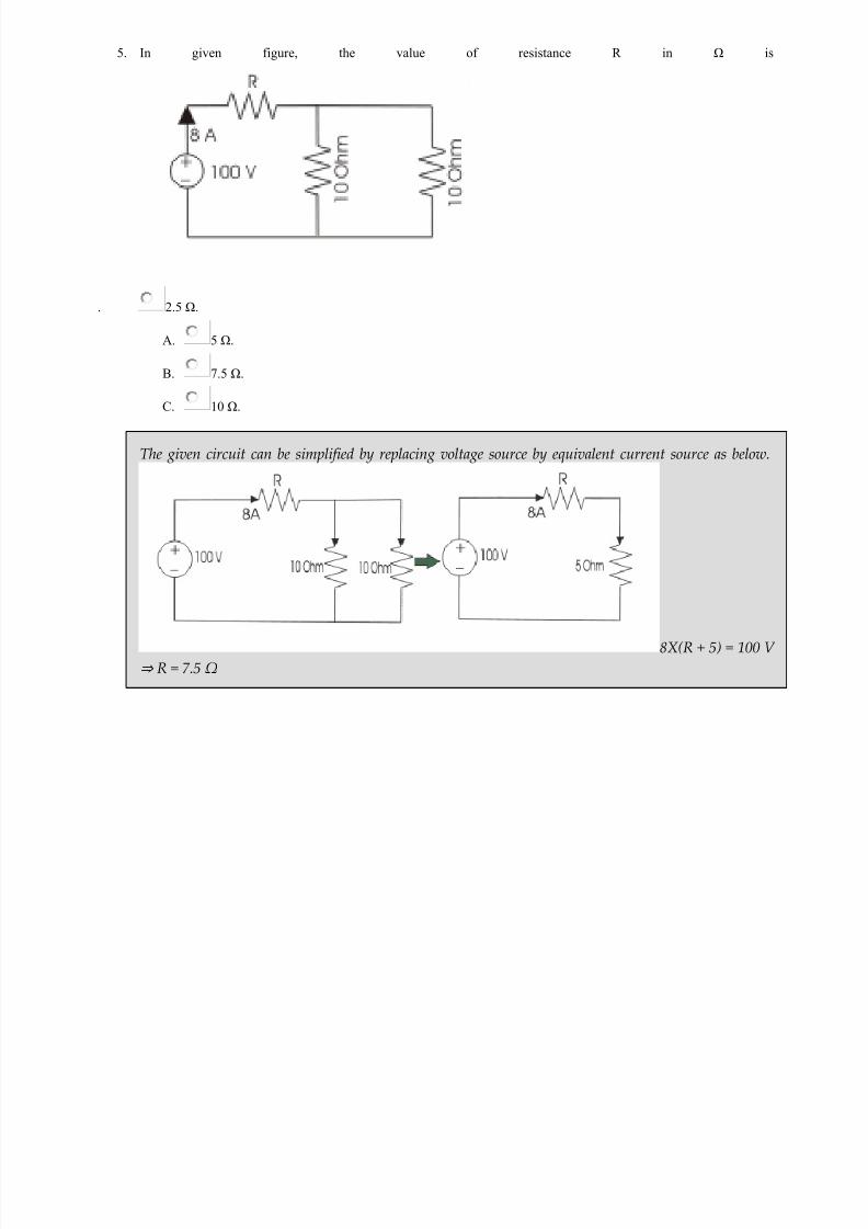
5. In given figure, the value of resistance R in Ω is
.
2.5 Ω.
A. 5 Ω.
B. 7.5 Ω.
C. 10 Ω.
The given circuit can be simplified by replacing voltage source by equivalent current source as below.
8X(R + 5) = 100 V⇒ R = 7.5 Ω

7/21/2019 Objective Questions Electrical Engineering.pdf
http://slidepdf.com/reader/full/objective-questions-electrical-engineeringpdf 54/150
6. A 35 V source is connected to a series circuit of 600 Ω and R as shown. If a voltmeter of internal resistance 1.2 kΩ isconnected across 600 Ω resistor, it reads 5V. The value of R is
. 2.4 kΩ.
A. 1.2 kΩ.
B.
3.6 kΩ.
C. 7.2 kΩ.
As the voltmeter of internal resistance 1.2 KΩ is connected across the 600 Ω resistor and it gives 5 Vreading, the circuit current I = 5/600 +5/1200 A = 0.0125 A. As supply voltage is 35 V, the voltage crossresistor R is 35 - 5 = 30 V
7. A certain network consists of large number of ideal linear resistances, one of which is designated as R and two constan
ideal source. The power consumed by R is P1 when only the first source is active and P 2 when only second source isactive. In both sources are active simultaneously then the power consumed by R is
. √P1 ± √P2.
A. (√P1 ± √P2)2.
B. P1 ± P2.
C. (P1 ± P2)2.
8. In the circuit given, I = 1 A for Is = 0. What is the value of I for Is = 2 A ?

7/21/2019 Objective Questions Electrical Engineering.pdf
http://slidepdf.com/reader/full/objective-questions-electrical-engineeringpdf 55/150
. 4 A.
A. 3 A.
B.
2 A.
C. 1 A.
9. In the circuit shown below, what is the voltage across 5Ω resistor ?
. − 30 V.
A.
30 V.
B. 1250 V.
C. − 1250 V. 10.
For the circuit shown in the given figure the current I is given by
.
2 A.
A. 1 A.
B. 3 A.
C. 4 A.

7/21/2019 Objective Questions Electrical Engineering.pdf
http://slidepdf.com/reader/full/objective-questions-electrical-engineeringpdf 56/150
11. For the circuit given in the figure the power delivered by the 2 V source is given by
. 4 W.
A. 2 W.
B.
− 2 W.
C.
− 4 W.
.
12. In the circuit shown in the figure, the value of V s is 0, when I = 4A. The value of I when V s = 16 V, is
. 6 A.
A. 12 A.
B. 10 A.
C.
8 A.
.

7/21/2019 Objective Questions Electrical Engineering.pdf
http://slidepdf.com/reader/full/objective-questions-electrical-engineeringpdf 57/150
13. Consider the following circuit: In this circuit, when Vs = 3V, I = 4A, when is the value of I when Vs = 12V ?
. 5 A.
A. 10 A.
B.
15 A.
C.
20 A.14.
In the figure given, the value of R is
. 12 Ω.
A. 18 Ω.
B. 24 Ω.
C. 10 Ω.

7/21/2019 Objective Questions Electrical Engineering.pdf
http://slidepdf.com/reader/full/objective-questions-electrical-engineeringpdf 58/150
15. In the given figure the value of the source voltage is
. 12 V.
A. 30 V.
B.
44 V.
C.
24 V.16.
) Three resistance of two ohms each are connected in star in the equivalent delta representation each resistance will
have a value of ________ohms.
3.4.
A. 6.
B. 0.6.
C. 5.2.
R A = RB = RC = 2 X 2 + 2 X 2 + 2X2 / 2 = 6 ohms .
17. Consider the following circuit: What is the value of current I in the 5 Ω resistor in the circuit given in the figure ?
. 0 A.
A.
2 A.
B. 3 A.

7/21/2019 Objective Questions Electrical Engineering.pdf
http://slidepdf.com/reader/full/objective-questions-electrical-engineeringpdf 59/150
C. 4 A.
18.
The value of V in the circuit shown in the given figure is
. 2 V.
A.
3 V.
B.
4 V.
C. 5 V.
19. In the given figure, the Thevenin equivalent voltage and impedance as seen from the terminals P-Q is given by
. 2 V and 5 Ω.
A. 2 V and 7.5 Ω.
B. 4 V and 5 Ω.
C.
4 V and 7.5 Ω.
7/21/2019 Objective Questions Electrical Engineering.pdf
http://slidepdf.com/reader/full/objective-questions-electrical-engineeringpdf 60/150
2 V, 5Ohm
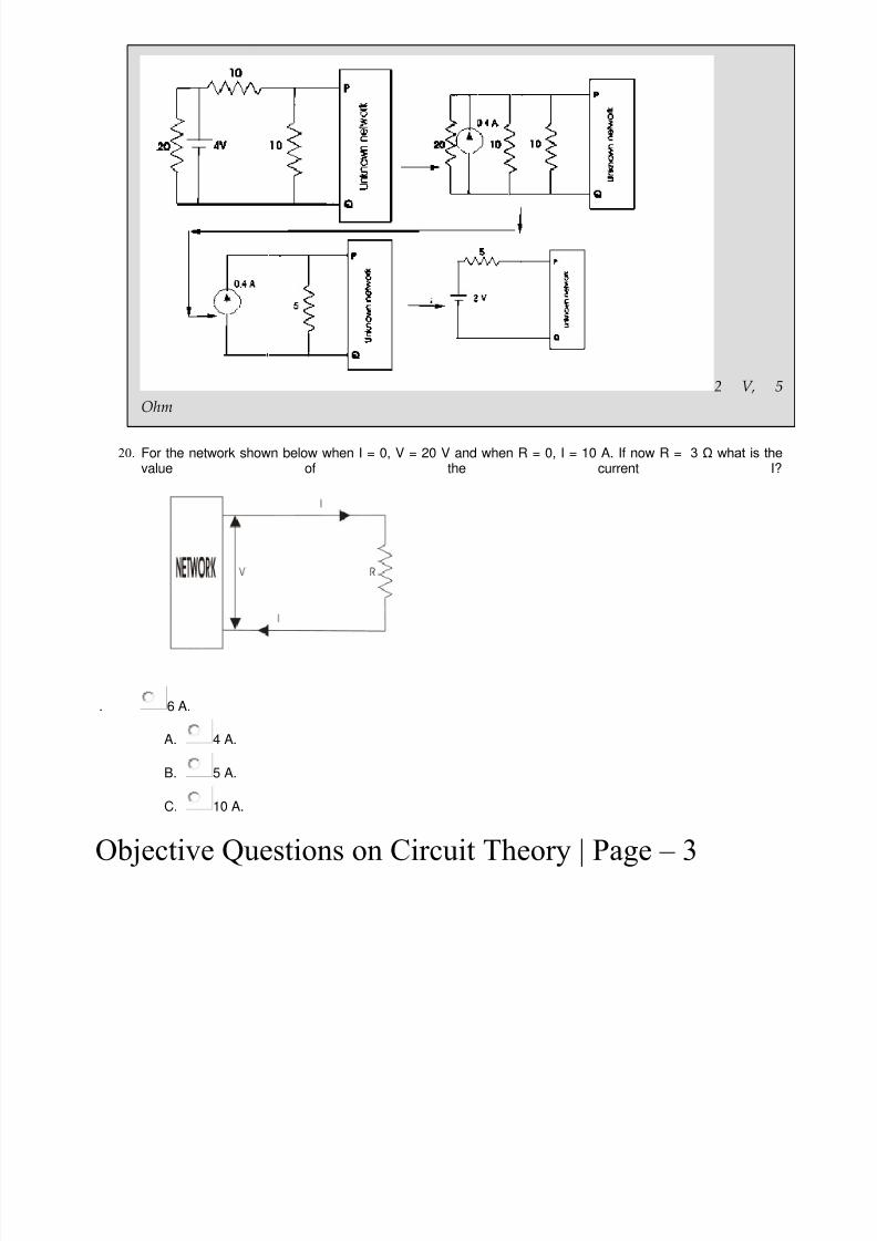
20. For the network shown below when I = 0, V = 20 V and when R = 0, I = 10 A. If now R = 3 Ω what is thevalue of the current I?
. 6 A.
A. 4 A.
B.
5 A.
C. 10 A.
Objective Questions on Circuit Theory | Page – 3

7/21/2019 Objective Questions Electrical Engineering.pdf
http://slidepdf.com/reader/full/objective-questions-electrical-engineeringpdf 61/150
1. For the circuit given in the figure, the Thevenin voltage and resistance as seen at AB are represented by
A. 5 V 10 Ω.
B. 10 V 10 Ω.
C. 5 V 5 Ω.
D.
54 V 15 Ω.
Same as 2065 V 10 Ω
2. Form factor is defined as ratio of
. average value to RMS value.
A. RMS value to average value.
B. maximum value to RMS value.
C. RMS value to maximum value.

7/21/2019 Objective Questions Electrical Engineering.pdf
http://slidepdf.com/reader/full/objective-questions-electrical-engineeringpdf 62/150
Form factor = rms value / avg value.
3. Peak factor is defined as ratio of
. maximum value to RMS value.
A. average value to RMS value.
B. RMS value to average value.
C. RMS value to maximum value.
Peak factor = maximum value/RMS value.
4. At resonance
. magnitude of capacitive reactance > magnitude of inductive reactance.
A. magnitude of capacitive reactance = magnitude of inductive reactance.
B. magnitude of capacitive reactance < magnitude of inductive reactance.
C. none of above.
Resonance is occurs at when inductive, capacitive reactance both are same i.e. , circuit is having onlyresistive components.
5.
A series R-L-C circuit has R=50 Ω, L=100 μH and C = 1 μF. The lower half power frequency of the circuit is
. 30.55 KHz.
A. 3.05 KHz.
B. 51.92 KHz.
C. 1.92 KHz.6. The period of the function cosπ ⁄ 4(t-1) is
.
8 Second.
A. 1 ⁄ 8 Second.
B. 4 Second.
C. 1 ⁄ 4 Second.
Here 2π ⁄ T = π ⁄ 4 ⇒ T = 8 Second.

7/21/2019 Objective Questions Electrical Engineering.pdf
http://slidepdf.com/reader/full/objective-questions-electrical-engineeringpdf 63/150
7. A T-section lowpass filter has series inductance 80 mH and shunt capacitance 0.022 µF. Determine cutofffrequency
. 7 KHz.
A. 7.58 KHz.
B. 7.8 KHz.
C.
8 KHz.
L = 80 mH, C = 0.022 µF , f c (cutoff frequency) = 1 ⁄ π√(LC) = 1 ⁄ π√(80X10 − 3)X(0.022X10 − 6) = 7.58KHz.
8. In a constant-k high pass filter having cutoff frequency of 12 kHz. Find out phase constant at 24 kHz
. 75°.
A.
60°.
B. 90°.
C. 45°.
β ( phase constant ) = 2sin − 1(f c/f) = 2sin − 1(12X103/24X103) = 60°.
9. In Constant K high- pass filter having cutoff frequency of 12 Khz, Findout attenuation at 4 Khz-
.
3.5.
A. 3.525.
B. 3.425.
C. 3.4.
α ( attenuation ) = 2cosh − 1(f c/f) neper = 2cosh − 1(12X103/4X103) = 3.525 neper.
10.
Find out the series arm capacitance & shunt arm inductance in a constant K-high pass filter, whenimpedance R0 = 600 Ω & cut off frequency = 4 Khz (Π - sec)
. 0.033 μF & 11.937 mH.
A. 0.4 μF & 12mH.
B. 0.05 μF & 13mH.
C. 0.02 μF & 10.9mH.

7/21/2019 Objective Questions Electrical Engineering.pdf
http://slidepdf.com/reader/full/objective-questions-electrical-engineeringpdf 64/150
C = 1 ⁄ 4πR0.f c = 1 ⁄ (4π600X4000) = 0.033 μF and L = R0 ⁄ 4π.f c = 600 ⁄ (4π4000) = 11.937 mH.
11. An RLC circuit has a resonance frequency of 160kHz and a Q-factor of 100. Its band width is
. 1.6 kHz.
A. 0.625 kHz.
B. 16MHz.
C. None of these.
Bandwidth, BΩ = f 0/QWhere f 0 = Resonant frequencyQ = Qulity factorBΩ = 160/100 = 1.6kHz.
12. A circuit which has W0 = 106 rad/sec (W0 = resonant frequency) C = 10 pf and Q = 100, must have aresistance of ___________kΩ.
5.
A. 100.
B. 10.
C. 1.
Q= Xc/R= 1/ W 0 C Q = 1 / 106 X 10 X 10-12 X 100 = 100 X 103 Ω .
13. A certain ac circuit has resistance of 10 ohm and impendence of 20 ohm. The p.f. of the circuit is
600.
A. 300.
B. 900.
C.
1/2.
Cosφ = R/Z = 10/20φ = cos-1(1/2)= 600.
14. The time constant of an RL circuit is 1 second and its inductance is 8 H, the resistance of the coil is _____ohms.
8.

7/21/2019 Objective Questions Electrical Engineering.pdf
http://slidepdf.com/reader/full/objective-questions-electrical-engineeringpdf 65/150
A. 1/8.
B. 0.25.
C. 1.
Time constant of RL circuit = L/RT = L/RI = 8/RR = 8 ohm.
15. The period of the function cos €/4(t-1) is -
8 Second.
A. 1/8 Second.
B.
4 Second.
C. 1/4 Second.
Here 2€/T=€/4 or,T=8 Second.
16. Clamping circuits are one which inserts
ac component in signal.
A.
dc component in signal.
B. both ac and dc.
C. none of these.
Clamping circuits / dc restorer are one which inserts dc components. These circuits are used intelevision amplifiers. A clamping circuit (also known as a clamper) will bind the upper or lower extremeof a waveform to a fixed DC voltage level. Clamp circuits are categorised by their operation; negative or positive, and biased or unbiased.
17. To a highly inductive circuit , a small capacitance is added in series . The angle between voltage and currentwill
decrease.
A. increase.
B. remain same.

7/21/2019 Objective Questions Electrical Engineering.pdf
http://slidepdf.com/reader/full/objective-questions-electrical-engineeringpdf 66/150
C. indeterminant.
the angle between voltage and current decreases when capacitance is added in series to a highlyinductive circuit.
18. Value of current at resonance in a series RLC circuit is affected by the value of
L.
A. C.
B. R.
C. None.
in series RLC circuit value of current is always affected by inductance of the circuit.
19. Superposition theorem is not applicable to networks having
linear elements.
A. non linear elements.
B. dependent current source.
C. transformer.
superposition is only applicable to networks having linear elements.
20. A network is linear if
response proportional to excitation function.
A. principle of superposition applies.
B. principle of homogenity applies.
C.
both b and c.
A linear network obeys both the principle of superposition and homogeneity.
Objective Questions on Circuit Theory | Page – 4
1. OLTF G(s)=s-2/s+2 is a

7/21/2019 Objective Questions Electrical Engineering.pdf
http://slidepdf.com/reader/full/objective-questions-electrical-engineeringpdf 67/150
A. all pass filter.
B. band stop filter.
C. band reject filter.
D. .
G(s)= s-2/s+2 denotes a zero at s=2 and a pole at s= -2 . So there exists a pole and a zero one at left halfofs plane and other at right half of s plane . They denote symmetrical mirror images- all pass filter.
2. When compared a 1st order LPF a 2nd order LPF has
. lower voltage gain.
A. higher voltage gain.
B.
higher cut off frequency.
C. faster drop in filter response.
2nd order LPF low pass filter have higher cut off frequency than 1st order low pass filter.
3. In active filter which element is absent
. inductor.
A.
capacitor.
B. both.
C. resistor.
in active filter inductor is absent which are bulky and expensive at lower frequency.
4. Advantage of active filter is
.
do not offer gain.
A. easy to tune.
B. both.
C. derive high impedance load.

7/21/2019 Objective Questions Electrical Engineering.pdf
http://slidepdf.com/reader/full/objective-questions-electrical-engineeringpdf 68/150
active filters offers gain and it is also easy to tune . It derives low impedance loads. These are theadvantages of active filter over passive.
5. Disadvantages of constant k type filter
. characteristic impedance unchanged in pass band.
A.
attenuation does not increase rapidly beyond cut off frequency.
B. both a and b.
C. none of these.
In m derived filter impedance is constant throughout passband and it is possible to get very rapidattenuation rise in stopband and beyond cut off frequency.
6.
Piezoelectric effect is carried out in. composite filter.
A. crystal filter.
B. m derived.
C. constant k prototype .
In piezoelectric effect when a mechanical strain is applied to one face of a suitably cut face of a
piezoelectric crystal ,it causes an emf to be developed in opposite surface of that piece.Reverse is alsotrue.
7. In Cauer 1 form last element in the network is
. Lseries.
A. Cseries.
B. Lshunt.
C.
Cshunt.
In cauer form 1 at s &rarr zero , if Z(s) is zero and &omega = 0 i.e for s tends to zero , the inductive pathis conductive. Thus the last element is an inductor.
8. If L&C are 4mH&0.0001µF respectively a current chop of magnitude 50 Amp would induced a voltage
. 200 Kv.

7/21/2019 Objective Questions Electrical Engineering.pdf
http://slidepdf.com/reader/full/objective-questions-electrical-engineeringpdf 69/150
A. 100 Kv.
B. 50 Kv.
C. 400 Kv.
e=√(L⁄C)=50√(4010-3-6
=100*103
=100 Kv
9. If the percentage reactance of an element is 20% & the fullload current is 50 Amp,the shortcircuit current wilbe-
. 250 Amp.
A. 300 Amp.
B. 200 Amp.
C. 350 Amp.
we know that Isc=I(100⁄%X)=50(100⁄20)=250 Amp
10. A current in a circuit is given by I(s) = (2s+8) ⁄ (s2 + 4s + 12). If the current flows through the 5 Ω resistor, findpower dissipated at t = 0
. 20 Watts.
A. 15 Watts.
B.
40 Watts.
C. 10 Watts.
i(0+) = lim(s → ∞) SI(s) or lim(s → ∞ ) s(2s + 8) ⁄ (s2 + 4s + 12) = 2 Amp. Power dissipated is [i(0 +)]2*5=20 Watts.
11. A current of 2+V2sin(214t+30)+2√2cos(952 t+45) is measured with a thermocouple,5amp.fullscale meterwhat is the meter reading:-
. 2 amp.
A. 5 amp.
B. (2+3√2)amp.
C. 3 amp.
RMS value=√(22+2⁄2+222⁄2)=3amp.

7/21/2019 Objective Questions Electrical Engineering.pdf
http://slidepdf.com/reader/full/objective-questions-electrical-engineeringpdf 70/150
12. A circuit with resistor, inductor, capacitor in series is resonant of 50 Hz. If all the values are now doubled, thenew resonant frequency is
f0 /2.
A. f0 /4.
B. 2f0.
C.
still f0.
f 0 =1 ⁄ *2π√(LC) and f 1 = 1/*2π√(2L2C), f 0 ⁄ f 1 = 2, f 1 = f 0 ⁄ 2.
13. Can a 250V, 5A single way switch be used in place of a 250V, 15A Switch
single way switch doesn't exist.
A. yes.
B.
no.
C. single way switch doesn't operate at such current ratings.
NO. The contact strip will melt if current more than 5A flows in 250V, 5A rated switch .
14. A periodic voltage having the fourier series v(t)=1+4sinΩt+2cosΩt volts is applied across a one ohm resisto.The power dissipated in the one ohm resistor is-
1 W.
A. 21 W.
B. 11 W.
C. 24.5 W.
Vrms=√(12+42 ⁄2+22 ⁄2) =√11 V ,p=V 2 ⁄R=11 W.
15. For the resonance circuit Ω0=105,Q=50,R=400Ω the value of C is-
250 PF.
A. 500 PF.
B. 1000 PF.
C. 125 PF.

7/21/2019 Objective Questions Electrical Engineering.pdf
http://slidepdf.com/reader/full/objective-questions-electrical-engineeringpdf 71/150
Ω0⁄R=50, L=50400⁄105=0.2,C=1⁄Ω02L=1⁄(0.2)1010.
16. An RLC series circuit resonates at a frequency wr the ratio of wr L/R = 10 the variable frequency voltageapplied to the circuit is 20 sin (Ω t = π/3)the voltage measured across the capacitance
200 / √2.
A.
220 / √2.
B. 20 / √2.
C. 1/2.
Voltage across inductor V L = V X Q. where V is rms of applied voltage and Q factor of the coilV m = 20V, W r L / R = Q = 10V L = (20 / √2) X 10 = 200 / √2 V.
17. An ac voltage of 200 V at 50Hz is applied to a coil which draws 5 amp and dissipates 1000 W. theresistance and impedance of the coil respectively are
40 ohms and 40 ohms.
A. 40 ohms and 200 ohms.
B. 25 ohms and 5 ohms.
C. 50 ohms and 200 ohms.
P = 1000 w => I 2 X R = 100052 X R = 1000 => R = 1000/25 = 40 ohm.
18. In what connection we get neutral
star.
A. delta.
B. mesh.
C. both a & b.
STAR connection is a method of connecting 3 phase circuit in such a way that one end of each phase of 3 phases are connected together thus forming a common star point called neutral.
19. What is the relation between line voltage & phase voltage in case of delta connection?
VL = VP.

7/21/2019 Objective Questions Electrical Engineering.pdf
http://slidepdf.com/reader/full/objective-questions-electrical-engineeringpdf 72/150
A. VL = 1/ √3 VP.
B. VL = √3 VP.
C. none of these.
Line voltage = Phase voltage in case of delta connection.
20. A capacitor of 50 microfarad is connected in series with a resistance of 120 ohms. If above circuit isconnected across 240V,50 hz 1 φ supply find capacitive reactance
63.7 ohm.
A. 0.015 ohm.
B. 135.86 ohm.
C. 1.765 ohms.
X c = 1/ 2 π f C = 1/ 2 X 3.14 X 50 X 50 X 10-6 = 63.7 ohm.
Objective Questions on Circuit Theory | Page – 5
1. Link In network theory refers to
A. B-N+1.
B. B-N-1.
C. N-1.
D. N-B-1.
B = BRANCH, N = NODES, TWIG = N-1LINK L = B-(N-1) = B-N+1
LINK / CHORD : is the branch of a graph that doesnot belong to the particular tree. It is simply called alink.
2. The voltage across R and L in a series PL circuit are found to be 200 v and 150 v respectively the rms valueof the voltage across the series combination is ___V.
. 360.
A. 250.
7/21/2019 Objective Questions Electrical Engineering.pdf
http://slidepdf.com/reader/full/objective-questions-electrical-engineeringpdf 73/150
B. 200.
C. 450.
V = √ V 2R X V 2L = √ 2002 + 150 2 = 250 V.
3.
Whenever current is supplied by a source its terminal voltage
. increases.
A. decreases.
B. remains constant.
C. increases exponentially.
Whenever current is supplied by a source, this current also flows through the internal resistanceconnected in series in the source. Because of voltage drop across the internal resistance, the terminalvoltage is decreased.
4. A current of 4 A flows in an ac circuit when 100 v dc is applied to it whereas it takes 250 v ac to produce thesame current the power factor of the circuit is
. 0.4.
A. 10.
B.
1.
C. 0.85.
With dc R = V / I = 100 / 4 = 25 ohmsWith ac Z = V / I = 250 / 4 = 62.5 ohms.Cos Φ = R / Z = 25 / 62.5 = 0.4
5. Which of the following cannot be connected in series unless they are identical
.
voltage source.
A. Current source.
B. both.
C. resistance.

7/21/2019 Objective Questions Electrical Engineering.pdf
http://slidepdf.com/reader/full/objective-questions-electrical-engineeringpdf 74/150
Current source cannot be connected in series unless identical because in series all individual currentsources have same values.
6. A reactance having an inductance of 0.15 H is connected in series with 10 ohm resistance.What will be theinductive reactance
. 48.15 ohm.
A. 47.1 ohm.
B. 1.5 ohm.
C. none of these.
Inductive reactance XL = 2 Π f L = 2 X 3.14 X 50 X 0.15 = 47.1 Ω
7. Kirchhoff's second law is based on law of conservation of
. charge.
A. energy.
B. momentum.
C. mass.
Kirchhoff's voltage law (KVL) is also called Kirchhoff's second law. The principle of conservation of
energy implies that the directed sum of the electrical potential differences (voltage) around any closednetwork is zero.
8. A series circuit consists of R = 20Ω, L = 20 mH, and ac supply 60V with f = 100 Hz. The current in R is
. 2.54 A.
A. 1.27 A.
B. 5.08 A.
C.
10.16 A.
The expression for impedance of series R - L circuit is Z = (R2 + 4.π2.f 2.L2)½
Here, R = 20Ω, L = 20 mH, V = 60V and f = 100 HzZ = [202 + 4 X 3.142X 100 2X (20 X 10 - 3)2]½ = 23.61 ΩTherefore, current through the circuit i.e both through resistor and inductor will be 60/23.61 = 2.54 A.
9. A series circuit consists of R = 20Ω, L = 20 mH, and ac supply 60V with f = 100 Hz. The voltage drop acrossR is
7/21/2019 Objective Questions Electrical Engineering.pdf
http://slidepdf.com/reader/full/objective-questions-electrical-engineeringpdf 75/150
. 30.6 V.
A. 50.8 V.
B. 40.8 V.
C. 24.4 V .
The expression for impedance of series R - L circuit is Z = (R2 + 4.π2.f 2.L2)½
Here, R = 20Ω, L = 20 mH, V = 60V and f = 100 HzZ = [202 + 4 X 3.142X 100 2X (20 X 10 - 3)2]½ = 23.61 ΩTherefore, current through the circuit i.e both through resistor and inductor will be 60/23.61 = 2.54 AThe voltage drop across R is V = IR = 2.54 X 20 V = 50.8 V.
10. A series circuit consists of R = 20Ω, L = 20 mH, and ac supply 60V with f = 100 Hz. The voltage drop acrossL is
.
39.1 V.
A. 31.9 V.
B. 45.5 V.
C. 50.5 V.
The expression for impedance of series R - L circuit is Z = (R2 + 4.π2.f 2.L2)½
Here, R = 20Ω, L = 20 mH, V = 60V and f = 100 Hz
Z = [202 + 4 X 3.142X 100 2X (20 X 10 - 3)2]½ = 23.61 ΩThe reactance of the circuit, X = 2.π.f.L = 2 X 3.14 X 100 X 20 X 10 - 3 = 12.56 Ω∴ current through the circuit i.e both through resistor and inductor will be 60/23.61 = 2.54 AVoltage drop across L is X.I = 12.56 X 2.54 = 31.9 V.
11. A series circuit consists of R = 20Ω, L = 20 mH, and ac supply 60V with f = 100 Hz. The phase angle ofcurrent in respect of supply voltage will be
. 40.4°.
A.
32.1°.
B. 28.8°.
C. 20.2°.
The expression for impedance of series R - L circuit is Z = (R2 + 4.π2.f 2.L2)½
Here, R = 20Ω, L = 20 mH, V = 60V and f = 100 HzZ = [202 + 4 X 3.142X 100 2X (20 X 10 - 3)2]½ = 23.61 Ω

7/21/2019 Objective Questions Electrical Engineering.pdf
http://slidepdf.com/reader/full/objective-questions-electrical-engineeringpdf 76/150
The reactance of the circuit, X = 2.π.f.L = 2 X 3.14 X 100 X 20 X 10 - 3 = 12.56 Ω∴ the phase angle of current in respect of supply voltage will be θ = sin - 1(X/Z) = sin - 1(12.56 / 23.61) =32.1°.
12. If a resistor and an inductor are connected in series across a voltage source. Which two parameters in thatcircuit increase if frequency of voltage source increases?
VL & Z.
A. Z & I.
B. VL & I.
C. VL & VR.
If frequency of the voltage source increases, the reactance of the inductor increases as because X L = 2π.f.Land if XL and that causes increase in the total impedance Z, of the circuit, which results decreasing the
current I through the circuit. If current is reduced, the voltage drop across the resistor V R is decreased Again voltage drop across the inductor is the difference of supply voltage and voltage drop across theresistor, hence voltage across inductor V L will increase.
13. If a resistor and an inductor are connected in series across a voltage source. Which two parameters in thatcircuit decrease if frequency of voltage source increases?
VL & Z.
A. VR & I.
B.
Z & I.
C. VL & VR.
If frequency of the voltage source increases, the reactance of the inductor increases as because X L = 2π.f.Land if XL and that causes increase in the total impedance Z, of the circuit, which results decreasing thecurrent I through the circuit. If current is reduced, the voltage drop across the resistor V R is decreased Again voltage drop across the inductor is the difference of supply voltage and voltage drop across theresistor, hence voltage across inductor V L will increase.
14. If a resistor and a capacitor are connected to form series R - C circuit across a voltage source. If frequencyof voltage source increases
the current increases.
A. the current decreases.
B. the current remain unaltered.
C. the current decreases abruptly.

7/21/2019 Objective Questions Electrical Engineering.pdf
http://slidepdf.com/reader/full/objective-questions-electrical-engineeringpdf 77/150
In series RC circuit if supply frequency is increased, the current increases. Because the impedance ofcapacitor is ..........That is capacitive impedance is inversely proportional to frequency. As capacitiveimpedance decreases with increase in frequency, the overall impedance of the series RC circuit isdecreased which results increase in current through the circuit.
15. A branch of a network is said to be active when it consists of one
resistor.
A. voltage source.
B. inductor.
C. capacitor.
When a branch of a network contains one or more sources it is called an active branch.
16. A branch of a network is said to be passive when it contains
voltmeter.
A. voltage source.
B. current source.
C. battery.
A branch that does not contain any source is known as a passive branch. Voltmeter is not a source.
17. Which of the following is not a bilateral?
resistor.
A. diode.
B. capacitor.
C. inductor.
A bilateral element conduct equally well in either directions. Such as resistor & inductor . When thecurrent voltage relation are different for the two directions of current flow, the element is said to beunilateral Diode is a unilateral element.
18. Which of the following characteristics is attributed to an ideal independent voltage source?
independent of magnitude of current supplied.

7/21/2019 Objective Questions Electrical Engineering.pdf
http://slidepdf.com/reader/full/objective-questions-electrical-engineeringpdf 78/150
A. dependent of the magnitude of current supplied.
B. dependent of the direction of flow of current.
C. none of above.
In independent ideal voltage source is such a source, which gives fixed voltage, irrespective of magnitudeand direction of current flowing through it.
19. Dependent source of current and voltage are those which have,
unidirectional characteristic.
A. output dependent on input.
B. independent of any other network variable.
C.
all above.
The source whose output voltage or current is a function of the voltage or current in another part of thecircuit is called dependent source.
20. The internal resistance of a practical voltage source is considered to be connected in
series.
A. parallel.
B. either parallel or series.
C. none of the above.
Whenever load is connected to the voltage source, its terminal voltage decreases become of its internalresistance. Hence the internal resistance of a practical voltage source is assumed to be connected inseries with the source.
Objective Questions no Conductance and Resistance 1. Conductance of any conductor is expressed as
A. ampere/watt.
B. mho.
C. volt2 /watt.

7/21/2019 Objective Questions Electrical Engineering.pdf
http://slidepdf.com/reader/full/objective-questions-electrical-engineeringpdf 79/150
D. watt/ampere2.
Conductance is reciprocal of resistance that means conductance = (resistance) - 1 . Hence unit ofconductance will be 1/ohm and this is known as mho.
2. Three element having conductance G1, G2 and G3 are connected in parallel. Their combined conductancewill be
. (G1 + G2 + G3) - 1.
A. G1 + G2 + G3.
B. 1/G1 + 1/G2 + 1/G3.
C. (1/G1 + 1/G2 + 1/G3) - 1.
We know that conductance is reciprocal of resistance i.e. resistance = 1 / conductance. Let's resistancesof the said conductors are R1 , R2 and R3 hence, G1 = 1/R1 , G2 = 1/R2 and G3 = 1/R3. The resistance of their parallel combination will be (1/R1 + 1/R2 + 1/R3) - 1 = (G1 + G2+ G3) - 1 . Therefore, conductance of thecombination will be G1 + G2 + G3.
3. Which of the following materials has highest electrical conductivity ?
. Steel.
A. Aluminium.
B.
Copper.
C. Silver.
Silver has highest conductivity among all other materials used as electrical conductor. Electricalconductivity measures material\'s ability to conduct an electric current. It is commonly represented bythe Greek letter σ (sigma). Its SI unit is siemens per metre.
4. The electrical conductivity of metal is typically of the order of (in ohm − 1m − 1)
. 107.
A. 105.
B. 10 − 4.
C. 10 − 6.
The electrical conductivity of metal is typically of the order of 107 ohm − 1m − 1.

7/21/2019 Objective Questions Electrical Engineering.pdf
http://slidepdf.com/reader/full/objective-questions-electrical-engineeringpdf 80/150
5. Pure metal generally have
. high conductivity and low temperature coefficient.
A. high conductivity and large temperature coefficient.
B. low conductivity and zero temperature coefficient.
C.
low conductivity and high temperature coefficient.
Pure metal always have high conductivity as well as high temperature coefficient. The resistance ofmetal greatly varies with temperature.
6. Poorest conductor of electricity is
. Aluminium.
A. Carbon.
B. Steel.
C. Silver.
Carbon is a non metal.
7. Which variety of copper has the best conductivity ?
. Pure annealed copper.
A. Induction hardened copper.
B. Hard drawn copper.
C. Copper containing traces of silicon.
Pure annealed copper has best conductivity.
8. Which variety of copper has the best mechanical strength ?
. Annealed copper.
A. Hard drawn copper.
B. Cast copper.
C. Soft copper.
7/21/2019 Objective Questions Electrical Engineering.pdf
http://slidepdf.com/reader/full/objective-questions-electrical-engineeringpdf 81/150
Hard drawn copper is not annealed after the drawing process. Annealing makes the copper more flexible.Hard drawn has at least 150% more tensile strength than annealed.
9. What will be the resistance if 10 resistors of 10 ohm each is connected in series
. 100 Ω.
A.
1 Ω.
B. 0.1 Ω.
C. 10 Ω.
Equivalent resistance of resistors connected in series = sum of the individual resistances. Here it is10+10+10+10+10+10+10+10+10+10 =100 Ω .
10.
If the three colour bands of a resistor are grey, violet & gold, what is the value of the resistor:-. 6.7 ohms.
A. 8.7 ohms.
B. 7.7 ohms.
C. 9.7 ohms.
The values of these colours are 8, 7 & multiplier of 0.1. Therefore the value of resistance will be 87*0.1 =
8.7 ohms.
11. Which of the following may be value of resistivity of copper at absolute zero in n ohm metre
. 0.020.
A. 3.12.
B. 6.24.
C. 1.56.
The resistivity of copper does not vanish at absolute zero. Instead, its level at absolute zero is known asthe residual resistance. Copper has a residual resistance of 0.020 nΩ m.
12. A circuit contains two un equal resistor in parallel
voltage drops across both are same.

7/21/2019 Objective Questions Electrical Engineering.pdf
http://slidepdf.com/reader/full/objective-questions-electrical-engineeringpdf 82/150
A. currents in both are same.
B. heat losses in both are same.
C. voltage drops are according to their resistive value.
Whatever may be the value of resistance the voltage drops, across all the resistors connected in parallel,are always same .
13. Three resistances have the following ratings A)150 Ω at 5%,B) 100 Ω at 5%,C)200 Ω at 5% the percentageerror when all the three are connected in series will be-
+6%.
A. +5%.
B. +7%.
C. +8%.
(150*5%+200*5%+100*5% )/450=5%
14. If the length of a wire of resistance R is uniformly stretched to n times its original value, what will be its newresistance
n2R.
A.
R/n2
.
B. n2 /R.
C. nR .15. The resistivity of semi-conductors at room temperatures is
0.01 to 50 ohm-cm.
A. 1000 to 1500 ohm-cm.
B. 109 to 1012 ohm-cm.
C. 1.6 × 10⁶ to 100 × 106 ohm-cm.
The resistivity of semi-conductors at room temperatures is 0.01 to 50 ohm-cm.
16. Addition of 0.3% to 4.5% silicon to iron
increases the electrical resistivity of iron.
A. reduces the saturation magnetization.

7/21/2019 Objective Questions Electrical Engineering.pdf
http://slidepdf.com/reader/full/objective-questions-electrical-engineeringpdf 83/150
B. increases the hysteresis loss.
C. none of the above..
Addition of 0.3% to 4.5% silicon to iron increases the electrical resistivity of iron.
17.
If the resistance of a conductor does not vary in accordance with the Ohm’s laws it is known as
Non-conductor.
A. Non-linear conductor.
B. Bad conductor.
C. Reverse conductor.
Ohm's law V = IR which is an equation of straight line so the resistance of a conductor does not vary inaccordance with the Ohm’s laws it is known as non-linear conductor
18. The current in the resistor R shown in figure will be
. 0.2A.
A. 0.4A.
B. 0.6A.
C.
0.8A.

7/21/2019 Objective Questions Electrical Engineering.pdf
http://slidepdf.com/reader/full/objective-questions-electrical-engineeringpdf 84/150
19. In given figure, the value of resistance R in Ω is
. 3.5Ω.
A. 2.5Ω.
B. 1Ω.
C. 4.5Ω.
The given circuit can be simplified by replacing voltage source by equivalent current source as below
The currentthrough 3.2 Ω resistor is 4.33 A hence voltage across it is 3.2X4.33 = 13.856 V and this is the voltageacross unknown resistor R. As current through R is 4 A and then R = 13.856/4 = 3.47 Ω
20. Which of the following has positive temperature coefficient ?
Germanium.
A. Gold.
B. Paper.
C. Rubber.
Normally metallic substance has positive temperature coefficient. Gold is a metallic substance.

7/21/2019 Objective Questions Electrical Engineering.pdf
http://slidepdf.com/reader/full/objective-questions-electrical-engineeringpdf 85/150
MCQs no Control System | Page – 1
1. A lead compensator used for a closed loop controller has the following transfer function- k(1+s/a)/(1+s/b)For such a lead compensator
A. a < b.
B.
b < a.C. a > kb.
D. a < kb.
zero at T.F.= − a, pole of T.F.= − b. For a lead compensator the zero is nearer to origin as compared to pole.
2. The transfer function of two compensator are given below − C1 =10(s+1)/(s+10) and C2 = (s+10)/10(s+1)
which one is correct
. C1 is a lag compensator & C2 is a lead compensator.
A. C1 is a lead compensator & C2 is a lag compensator.
B. Both C1 & C2 are lead compensator.
C. Both C1 & C2 are lag compensator.
For a lead compensator, the zero is nearer to the origin & lag compensator the pole is nearer to the
origin. Here in numerator (zero) s = − 1, denominator (pole) = − 10, So s = − 1 nearer to the origin. SoC1 = Lead compensator and C2 is lag compensator.
3. Time taken for the response to raise from zero to 100% for very first time is called
. rise time.
A. settling time.
B. delay time.
C. peak time.
transient response characteristics of the control system is specified in terms of time domainspecifications. Time taken for the response to raise from zero to 100% for very first time is called risetime. For under damped system it is 0-100 % For over damped system it is 10-90 % For criticallydamped system it is 5-95% .
4. Time taken by the response to reach and stay within a specified error is called

7/21/2019 Objective Questions Electrical Engineering.pdf
http://slidepdf.com/reader/full/objective-questions-electrical-engineeringpdf 86/150
. Raise time.
A. Peak time.
B. Settling time.
C. Peak over shoot.
Settling time is defined as the time required for the response to decrease & stay within specified percentage of its final value.(Generally 2% or 5% tolerance band)Time- constant of the system=1⁄ζωn=TT s=4 x Time-constant=4⁄ζωn for a tolerance band + 2% of steady stateT s=3 x Time-constant=3⁄ζωn for 5% tolerance band. Time taken by the response to reach and stay withina specified error is called settling timeUsually tolerable error is 2-5% of final value.
5.
An open loop, represented by the transfer function G(s) = (s-1) ⁄ (s+2)(s+3), is
. stable & of the non-minimum phase type.
A. stable & of the minimum phase type.
B. unstable & of the minimum phase type.
C. unstable & of the non minimum phase type .
G(s) = (s-1) ⁄ (s+2)(s+3) here one zero at s = 1, Two poles at s = − 2, s = − 3, since zero lies in RHS of s - plane. It is non minimum phase type, Since both poles lies in LHS of s - plane, so system is stable.
6. A function y(t) satisfies the following differential equation: dy ⁄ dt + y(t) = δ(t). Where δ(t) is the delta functionAssuming zero initial condition and denoting the unit step function by u(t), y(t) can be formed as
. et.
A. e-tu(t).
B. e-t.
C.
etu(t).
dy ⁄ dt + y(t) = δ(t) or, both side taking Laplace transform, y(s)(s+1) = 1 or, y(s) = 1 ⁄ (s+1), takinginverse Laplace transform y(t) = e-tu(t).
7. Lead network is used to improve
. improve transient response.

7/21/2019 Objective Questions Electrical Engineering.pdf
http://slidepdf.com/reader/full/objective-questions-electrical-engineeringpdf 87/150
A. both a and c.
B. increase bandwidth.
C. improve steady state response.
lead network improves transient response and increases margin of stability and increases bandwidth .
8. Type and order of transfer function G(s)=K/s(s+2)
. 1, 2.
A. 2, 1.
B. 0, 2.
C. 1, 1.
Type:total no of poles in origin of the TF and order:total power of s in denominator. Here total no. of polelocate at the origin is-1, so type of the transfer function is-1, Here total power of s in denominator is-2So, the order of the transfer function is-2.
9. Name test signals used in time response analysis
. all of b, c, d.
A. unit step.
B. unit ramp.
C. impulse.
all these signals are used in time response analysis.
10. A system is stable for
. G.M & P.M both +ve.
A. G.M & P.M both -ve.
B. G.M -ve.
C. P.M -ve.
For a system to be stable both G.M -GAIN MARGIN & P.M -PHASE MARGIN are positive. Gaincrossover frequency is equal to phase crossover frequency.

7/21/2019 Objective Questions Electrical Engineering.pdf
http://slidepdf.com/reader/full/objective-questions-electrical-engineeringpdf 88/150
11. T.F of zero order hold response is
. (1/s)X1-est.
A. (1/s)X1-e-st.
B. (s)X1-est.
C.
(1/s)Xe
-st
.
(1/s)X1-e-st is transfer function of zero order hold response.
12. A linear time invariant system has an impulse response e2t for t>0 . If initial condition are 0 and input is e 3t
the output for t>0 is
e2t - e3t.
A. e3t - e2t.
B.
e2t + e3t.
C. e5t.
h(s)= 1/(s-2), X(s) = 1/(s-3) ; output=h(s)X(s) = 1/(s-2)(s -3)= e3t - e2t.
13. In control system integrator is represented by
s.
A.
s2.
B. 1/ s2.
C. 1/s.
intergrator is always reresentated by 1/s i.e 1 pole at the origin. Differentiator is represented by s i.e 1zero at the origin.
14.
For lead compensator pole lies on LHS before zero.
A. on origin.
B. on LHS.
C. on RHS.

7/21/2019 Objective Questions Electrical Engineering.pdf
http://slidepdf.com/reader/full/objective-questions-electrical-engineeringpdf 89/150
In Lead compensator network pole lies on LHS and pole lies before zero. Zero lies before pole on LHS incase of lag compensator .
15. The phase of lead compensator of the system G(s)= s+a/s+b is maximum at
ab.
A.
√ ab.
B. √ a/b.
C. a/b.
phase of this lead compensator system is max. at &radic ab .
16. Number of roots in left hand half of s plane if characteristic equation is s3 -4 s 2 + s + 6=0
1.
A. 2.
B. 3.
C. 0.
TOTAL ROOTS- RHS ROOTS=(3-2)= 1
17.
The value of gain margin of the system having G(s)H(s)=8&frasl(s+2)3 is-
8.
A. 2.
B. 6.
C. 4.
Here -180 Degree=3 tan-1
(ωpc⁄2)*ωpc=Phase crossover frequency) or,ωpc=2√3Gh(ω=ωpc)=8⁄(444)=1/8 ,Here 1⁄ 8 is Magnitude(M) ,so GM=(1⁄M)=8
18. The second order system is defined by 25⁄(s2+5s+25) is given step input. The time taken for the output tosettle with in 2% of input is-
1.65 sec.
A. 1.2 sec.
B. 2 sec.

7/21/2019 Objective Questions Electrical Engineering.pdf
http://slidepdf.com/reader/full/objective-questions-electrical-engineeringpdf 90/150
C. 0.4 sec.
settle time is=4&fral;(ζωn)=(4⁄0.55)=1.65 sec.
19. The amplitude spectrum of a Gaussion pulse is-
uniform.
A. a sin function.
B. Gaussion.
C. impulse function.
The amplitude spectrum of a Gaussian pulse is always Gaussion.
20.
The characteristic equation of a feedback control =2s4+s3+3s2+5s+10=0 .The no of roots in the right half ofthe s-plane
2.
A. 3.
B. 4.
C. 0.
There are two sign change in in right half of the s-plane.
MCQs no Control System | Page – 2
1. If a body has identical properties all over, it is known as
A. Elastic.
B. Homogeneous.
C. Isotropic.
D. none of them.
"Homogeneous" is having all parts the same or similar in type.
2. A function of one or more variable which conveys information one to nature of physical phenomenon iscalled

7/21/2019 Objective Questions Electrical Engineering.pdf
http://slidepdf.com/reader/full/objective-questions-electrical-engineeringpdf 91/150
. signal.
A. interference.
B. system.
C. noise.
Signal is also defined as any physical quantity that varies with time, space or any other independentvariable.
3. The dc gain of a system represented by the transfer function 12 ⁄ (s+1)(s+3) is
. 1.
A. 2.
B.
5.
C. 10.
d.c. gain T(s) at s = 0 , 12 ⁄ (0+2)X(0+3) = 12 ⁄ 6 = 2.
4. The transfer function of a system given by − 100/(s2 + 20s+100) the system is
. an over damped.
A.
a critically damped.
B. an under damped.
C. a unstable.
M(s) = W n2/(s2 + 2ζW ns + W n2), 2ζW n + 20. So W n = 1, here W n = under damped natural frequency. ζ =damping ratio. If ζ = 1, it is critically damped system.
5. G(s) = ( s + 6 ) / s( s – 2 )( s – 4 ). Find the order of a system.
. 2.
A. 3.
B. 4.
C. 5.
7/21/2019 Objective Questions Electrical Engineering.pdf
http://slidepdf.com/reader/full/objective-questions-electrical-engineeringpdf 92/150
Generally order of the system can be given by denominator of transfer function. The highest power of Sis 3 in the denominator of transfer function.
6. G(s) = ( s + 4 ) / s2( s + 2 )( s + 4 ). Find the type of the system.
. 2.
A.
3.
B. 4.
C. 1.
Type of the system the no. of poles located at the origin. Here the no of pole at origin = 2.
7. A negative feedback closed loop system is supplied to an input of 5 volt. The system has a forward gain of1& a feedback gain of 1.What is the output voltage
. 1.0 Volt.
A. 1.5 Volt.
B. 2.5 Volt.
C. 2.0 Volt.
We know that negative feedback closed loop system C(s)/R(s) = output/input = G(s)/1 + G(s)H(s)
G(s)=Forward gain, H(s)=Feedback gain. C(s) = R(s)G(s)/1+G(s)H(s) = 5X1/(1 + 1X1 ) = 2.5 Volt.
8. A system of constant voltage and constant frequency is called --------------------- system.
. feedback.
A. infinite.
B. zero.
C. none of the above.
A system of constant voltage and constant frequency regardless of load is called infinite bus bar system.
9. None of the poles of a linear control system lie in the right half of s plane . For a bounded input, the output ofthis system
. always bounded.
A. could be unbounded.

7/21/2019 Objective Questions Electrical Engineering.pdf
http://slidepdf.com/reader/full/objective-questions-electrical-engineeringpdf 93/150
B. tends to zero.
C. none of these.
for a linear control system with no poles in RHS of s plane including roots on jw axis with boundedinput, output may be unbounded
10. Number of sign changes in the entries in 1st column of Routh array denotes the no. of
. roots of characteristic polynomial in RHP.
A. zeroes of system in RHP.
B. open loop poles in RHP.
C. open loop zeroes in RHP.
Number of sign change in the 1st column of routh array denotes number of roots of the system in RH ofs plane.
11. A cascade of three linear time invariant systems is causal & unstable. From this we conclude that-
. each system in the cascade is individually caused & unstable.
A. at least one system is unstable & at least one system is causal.
B. at least one system is causal & all systems are unstable.
C. the majority are unstable & the majority are causal.
To whole system is causal & unstable .There ,must be at least one system causal & one unstable out ofthree.
12. In the integral control of the single area system frequency error is reduced to zero. Then
integrator output & speed changer position attain a constant value.
A.
integrator o/p decreases but speed changer position moves up.
B. integrator o/p increases but speed changer position comes down.
C. integrator o/p decreases & speed changer position comes down.
In the integral control of single area system, when the system frequency error is reduced to zero, theintegrator output & the speed changer position attain a constant value..

7/21/2019 Objective Questions Electrical Engineering.pdf
http://slidepdf.com/reader/full/objective-questions-electrical-engineeringpdf 94/150
13. When the polynomial is Hurwitz,
function is not real.
A. the roots of function have real parts which are to be zero/negative..
B. all zeroes lie in the right half of the s-plane.
C.
none of this.
The polynomial is Hurwitz then the roots function have real parts which are to be zero / negative.
14. Time response for a second order system depends on value of . If = 0 then the system is called as
un-damped system.
A. under damped system.
B. critically damped system.
C. over damped system.
the damping ratio is a dimensionless measure describing how oscillations in a system decay after adisturbance. Many systems exhibit oscillatory behavior when they are disturbed from their position ofstatic equilibrium. If ζ is zero then there will be no damping, hence it is called un-damped system.Where the spring–mass system is completely loss less, the mass would oscillate indefinitely, with eachbounce of equal height to the last. This hypothetical case is called un-damped.
15.
Time response for a second order system depends on value of . If >1 then the system is called as
un-damped system .
A. under damped system.
B. over damped system.
C. critically damped system.
If the system contained high losses, for example if the spring–mass experiment were conducted in aviscous fluid, the mass could slowly return to its rest position without ever overshooting. This case iscalled over damped. For over damped system zeta is greater than 1.
16. Time response for a second order system depends on value of . If = 1 then the system is called as
un-damped system.
A. under damped system.

7/21/2019 Objective Questions Electrical Engineering.pdf
http://slidepdf.com/reader/full/objective-questions-electrical-engineeringpdf 95/150
B. over damped system.
C. critically damped system.
between the over damped and under damped cases, there exists a certain level of damping at which thesystem will just fail to overshoot and will not make a single oscillation. This case is called critical
damping.
17. Time response for a second order system depends on value of . If = (0 to 1) then the system is called as
under damped system.
A. un-damped system.
B. over damped system.
C. critical damped system.
Commonly, the mass tends to overshoot its starting position, and then return, overshooting again. Witheach overshoot, some energy in the system is dissipated, and the oscillations die towards zero. This caseis called under damped.
18. For a unity feedback control system open loop transfer function G(s)= 10/s(s+1) then position error constantis
0.
A.
20.
B. ∞.
C. 40.
Position error constant is K p = limit0 G(s) H(s) = s010/s(s+2).
19. For a unity feedback control system open loop transfer function G(s)= 10/s(s+1) then velocity error constantis
10.
A. 50.
B. ∞.
C. 0.

7/21/2019 Objective Questions Electrical Engineering.pdf
http://slidepdf.com/reader/full/objective-questions-electrical-engineeringpdf 96/150
velocity error constant is K v
20. For a unity feedback control system open loop transfer function G(s)= 10/s(s+1) then acceleration errorconstant is
0.
A.
50.
B. ∞.
C. 20.
Acceleration error constant isK a = limit s→0 s2 G(s) H(s) = s → 0 s2
Objective Questions on Digital Electronics 1. Which of these sets of logic gates are designated as universal gates
A. NOR, NAND.
B. XOR, NOR, NAND.
C. OR, NOT, AND.
D. NOR, NAND, XNOR.
Using any one of these 2 gates-NAND, NOR we can design all logic gates.
2. Which one of the following is not a vectored interrupt:
. TRAP.
A. INTR.
B. RST 7.5.
C. RST 3.
Here TRAP, INTR, RST 7.5 are vectored interrupt. But RST 3 is not a non vectored interrupt.
3. The 2’s complement of the number of 1010101
. 0101011.
A. 0101010.

7/21/2019 Objective Questions Electrical Engineering.pdf
http://slidepdf.com/reader/full/objective-questions-electrical-engineeringpdf 97/150
B. 1101010.
C. 1110011.
The binary number is 1010101. We know that 2’s complement = 1’s complement + 1. So 1’s complemenof 1010101 is 0101011. Then add with 1 , we get 2’s complement 101011 + 1 = 0101011.
4. In the toggle mode a JK flip-flop has
. J=0, K=0.
A. J=1, K=1.
B. J=0, K=1.
C. J=1, K=0.
J=0 K=0-no change condition between pre-state & next state, J = 0, K = 1 - it is always reset conditionmeans next state is always 0, J = 1, K = 0 - it is always set condition means next state is always 1, J = 1,K = 1 - it is toggle condition means when pre-state is 1 then next state is 0 or when pre-state is 0 thennext state is 1.
5. The resolution of a 12 bit analog to digital converter in percent in-
. 0.01220.
A. 0.02441.
B. 0.04882.
C. 0.09760.6. What will be Excess-3 code for decimal (584)?
. (0111 0100 1000).
A. (1000 1011 0111).
B. (1011 0111 1000).
C. (1000 0111 1110).
5 8 4 + 3 3 3 = 8 11 7. Then 8 is a decimal no. So it is converted to binary when result is 1000, 11convert to binary 1011, 7 convert to binary-0111. So result is (1000 1011 0111).
7. The number of comparators in a parallel conversion type 8-bit analog to digital converter is
. 8.

7/21/2019 Objective Questions Electrical Engineering.pdf
http://slidepdf.com/reader/full/objective-questions-electrical-engineeringpdf 98/150
A. 16.
B. 255.
C. 256.
Number of comparators = (2N
- 1) = (212
- 1) = 255 (N =no. of bits).
8. Excess 3 code is known as
. weighted code.
A. redundancy code.
B. self complementing code.
C. algebraic code.
Complement of Excess 3 code is 9\'s complement of that digit in excess 3. So excess 3 code is also calledself complementing code.
9. 8085 microprocessor has how many pins
. 30.
A. 39.
B.
40.
C. 41.
Intel 8085 NMOS microprocessor is a 8 bit , 40 pins IC. It is a 40 pin I.C. package fabricated on a singleLSI chip.The Intel 8085 uses a single +5Vd.c. supply for its operation.Its clock speed is about 3 MHz.The clock cycle is 320 ns.It has 80 basic instructions & 246 opcodes.
10. How many flip flops are required to build a binary counter circuit to count from 0 to 1023?
.
6.
A. 10.
B. 24.
C. 12.
Total count=1024, 2N =1024 or, 2N =210 or, N =10(no.of Flipflops).

7/21/2019 Objective Questions Electrical Engineering.pdf
http://slidepdf.com/reader/full/objective-questions-electrical-engineeringpdf 99/150
11. In 8085 microprocessor, the RST6 instruction transfer programme execution to following location-
. 0030H.
A. 0024H.
B. 0048H.
C.
0060H.
6*8=(48)10=0030H..
12. HLT opcode means
load data to accumulator.
A. store result in memory.
B. load accumulator with contents of register.
C. end of program.
HLT opcode in 8085 microprocessor means end of program.
13. In flip flop clock is present but in latch clock is
present always.
A. absent always.
B. may be present/absent.
C. none.
synchronous circuits change their states only whenclock pulses are present.The latch with additionalcontrol input(clock,enable input) is called flipflop.
14. Counter is a
combinational circuit.
A. sequential circuit.
B. both.
C. none.

7/21/2019 Objective Questions Electrical Engineering.pdf
http://slidepdf.com/reader/full/objective-questions-electrical-engineeringpdf 100/150
A counter is a sequential circuit that keeps a record of the clock pulses sent through it. Like a register, acounter also consists of a group of flip-flops. However, a counter has a characteristics internal sequenceof states through which it passes when a series of clock pulses are fed to it. Counters are divided intocategories: ripple(or asynchronous) counters and synchronous counters.
15. The 2's complement of 17 is
101111.
A. 110001.
B. 101110.
C. 111110.
17=010001 , 1's complement=101110, 2's complement=101111.
16. 1’s complment of 17 is
01110.
A. 10001.
B. 10111.
C. 11100.
17=10001, 1’s complement of 17=01110. For 1’s complement 0 is written as 1 and 1 is writtenas o.
17. A 10 bit A/D conveter is used to digitize an analog signal in the 0 to 6 volt. The maximum peak to ripplevoltage that can be allowed in the D.C. supply voltage is
6 milivolt.
A. 5 milivolt.
B. 5.85 milivolt.
C. 10 milivolt.
Smallest incremental change = 1 ⁄ 210 = 1 ⁄ 1024. So for 6 volt incremental change = 6 ⁄ 1024 = 5.85 MilliVolt.
18. If a counter having 10 flipflops is initially at 0,What count will if hold after 2060 pulses:-
000 000 1000.

7/21/2019 Objective Questions Electrical Engineering.pdf
http://slidepdf.com/reader/full/objective-questions-electrical-engineeringpdf 101/150
A. 000 000 1110.
B. 000 001 1100.
C. 000 000 1100.
In complete one cycle 1024 pulses2060⁄1024=2048⁄2cycles,Balance=2060-2040=12 pulses.Binary no.of12 is=000 000 1100
19. A switch-tail ring counter is made by using a single D-FF , the following circuit is-
T FF.
A. D FF.
B. S-R FF.
C.
J-K FF.
In a switch tail ring counter , using DFF,the complementary of output(Q')is connected to D input for asingle D-FF it becomes a TT FF.
20. The fast logic Family is
ECL.
A. DRL.
B. TRL.
C. TTL.
ECL(Emitter coupled logic) is the fast logic family. Because the switching transistors do not go intosaturation in either the on / off state. ECL is sensitive to a threshold level only.
Objective Questions on Magnetic Field
1. A 2m long conductor, carries a current of 50 A at a magnetic field of 100 x 10 − 3T. The force on theconductor is
A. 10 N.
B. 100 N.
C. 1000 N.
D. 10000 N.

7/21/2019 Objective Questions Electrical Engineering.pdf
http://slidepdf.com/reader/full/objective-questions-electrical-engineeringpdf 102/150
The magnetic of the force on the conductor, F in the case of conductor of length l meter arranged at rightangles to the magnetic field B tesla and carrying a current I, is given by F = B I P
2. Materials which lack permanent magnetic dipoles are called
. dia-magnetic.
A.
ferro-magnectic.
B. semi-magnetic.
C. none of the above.
Materials which lack permanent magnetic dipoles are called diamagnetic. Unlike a ferromagnet, adiamagnet is not a permanent magnet. Its magnetic permeability is less than μ0 (the permeability of freespace).
3. Which of the following is the ferroelectric material ?
. Rochelle salt.
A. Potassium dihydrogen phosphate.
B. Barium titanate.
C. All of the above.
Ferroelectricity is a property of certain materials that have a spontaneous electric polarization that canbe reversed by the application of an external electric field. The term is used in analogy to ferromagnetism. Ferromagnetism was already known when ferroelectricity was discovered in 1920 in Rochelle salt .Potassium dihydrogen phosphate and Barium titanate are also examples of ferroelectric materials.
4. Materials having a high dielectric constant, which is non-linear, are known as
. elastomers.
A. ferroelectric materials.
B. super die-electrics.
C. hard die-electrics.
Because of its property of electric polarization.
5. In ferromagnetic materials
. the atomic magnetic moments are antiparallel and unequal.

7/21/2019 Objective Questions Electrical Engineering.pdf
http://slidepdf.com/reader/full/objective-questions-electrical-engineeringpdf 103/150
A. the atomic magnetic moments are parallel.
B. the constituents is iron only.
C. one of the constituent is iron.
In ferromagnetic materials the atomic magnetic moments are parallel.
6. When the atomic magnetic moments are randomly oriented in a solid its magnetic behavior is termed as
. semi-magnetic.
A. anti-ferromagnetic.
B. paramagnetic.
C. poly crystalline.7. The intensity of magnetization, M, of a ferro magnetic solid
. increases with increasing temperature.
A. is independent of temperature.
B. decreases with increasing temperature.
C. depends on method of heating.
The intensity of magnetization of a ferro magnetic solid is independent of temperature.
8. When a ferromagnetic substance is magnetized small changes in dimensions occur . Such a phenomenon isknown as
. magnetostriction.
A. magnetic hysteresis.
B. magneto-calorisation.
C. magnetic expansion.
Magnetostriction is a property of ferromagnetic materials that causes them to change their shape ordimensions during the process of magnetization.
9. Magnetic recording tape is most commonly made from
. ferric-oxide.
A. silicon-iron.
7/21/2019 Objective Questions Electrical Engineering.pdf
http://slidepdf.com/reader/full/objective-questions-electrical-engineeringpdf 104/150
B. small particles of iron.
C. iron-dust.
Magnetic tape is a medium for magnetic recording, made of a thin magnetizable coating on a longnarrow strip of plastic film. Magnetic recording tape is most commonly made from silicon - iron .
10. The permeability of iron can be increased by
. purifying it.
A. alloying with cobalt.
B. reducing carbon percentage.
C. increasing carbon percentage.
The permeability of iron can be increased by alloying with cobalt.
11. A material with unequal anti-parallel atomic magnetic moments is
. an anti-ferromagnet.
A. ferrimagnet.
B. a ferrite.
C.
non-magnetic.
An anti-ferromagnet is a material with unequal anti-parallel atomic magnetic moments.
12. The temperature beyond which substances lose their ferroelectric properties, is known as
Curie temperature.
A. Critical temperature.
B.
Inversion temperature.
C. Conversion temperature.
Materials are only ferromagnetic below their corresponding Curie Temperatures . Ferromagneticmaterials are magnetic in the absence of an applied magnetic field. Curie temperature or Curie point, isthe temperature where a material\'s permanent magnetism changes to induced magnetism or vice versa
13. Positive magnetostriction exists when

7/21/2019 Objective Questions Electrical Engineering.pdf
http://slidepdf.com/reader/full/objective-questions-electrical-engineeringpdf 105/150
dipoles are repel other.
A. dipoles are attract each other.
B. both are correct.
C. none of above.
During magnetization process of magnet the dipoles are attract and repel each other. Positivemagnetostriction exists when dipoles are repel each other.
14. The energy stored in the magnetic field at a solenoid 10cm long and 4cm diameter wound with 2000 turns ofwire carrying a current at 20A, is
24 joules.
A. 12 joules.
B. 30 joules.
C. 15 joules.
L= (N 2μ0 A)/L = ((2000 X 2000)(4π X 10 − 7)(π/4)(16 X 10 − 4))/0.1 =0.06 HEnergy= (1/2) x (0.06) (400) = 12 joules.
15. Two coils have inductances L1 = 1200 mH and L2 = 800 mH. They are connected in such a way that flux inthe two coils aid each other and inductance is measured to be 2500 mH then Mutual inductance between
the coils is ___________mH.
225.
A. 250.
B. 150.
C. 145.
Flux in two coils aid each other inductance of the combination
L= L1 + L2 + 2 X M2500 = 1200 + 800 + 2 X M2 X M =500 or M =250 mH.
16. the coils having self inductance of 10mH and 15Mh have an effective inductance of 40mH , when connectedin series aiding. What will be the equivalent inductance if we connect them in series opposing
20 mH.
A. 5 mH.
7/21/2019 Objective Questions Electrical Engineering.pdf
http://slidepdf.com/reader/full/objective-questions-electrical-engineeringpdf 106/150
B. 0 mH.
C. 10 mH.
L=L1 + L2 +2M ,when ordinary40=10+15+2M
2M=15MhL=L1 + L2 -2M ,when opposingL=10mH
17. 1 Tesla =
1 wb- m2.
A. 1 wb/ m2.
B. 1 wb .
C. 1 wb/m.
1TESLA = 1 wb/m 2
18. Two parallel plates are separated by a distance of d meter and voltage pap plied across the is V volts. Thefield intensity is given by
V/d.
A.
V × d 2.
B. V2.
C. V × d.
The field intensity can be defined as voltage per unit distance, hence = V ⁄ d
19. In an AC circuit, containing pure inductance, the voltage applied is 120 V, 50 Hz while the current is 10AFind the value of inductance.
35 mH.
A. 34 mH.
B. 30 mH.
C. 38 mH.
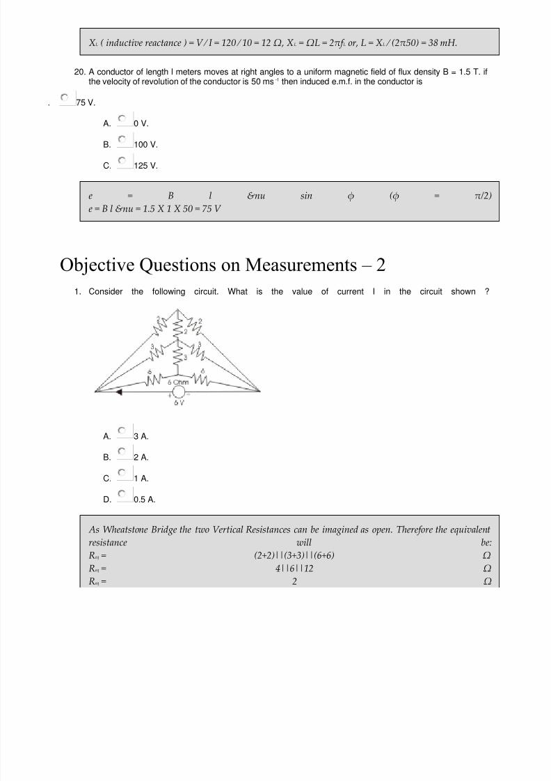
7/21/2019 Objective Questions Electrical Engineering.pdf
http://slidepdf.com/reader/full/objective-questions-electrical-engineeringpdf 107/150
XL ( inductive reactance ) = V ⁄ I = 120 ⁄ 10 = 12 Ω, XL = ΩL = 2πf L or, L = XL ⁄ (2π50) = 38 mH.
20. A conductor of length l meters moves at right angles to a uniform magnetic field of flux density B = 1.5 T. ifthe velocity of revolution of the conductor is 50 ms-1 then induced e.m.f. in the conductor is
75 V.
A.
0 V.
B. 100 V.
C. 125 V.
e = B l &nu sin φ (φ = π/2)e = B l &nu = 1.5 X 1 X 50 = 75 V
Objective Questions on Measurements – 2
1. Consider the following circuit. What is the value of current I in the circuit shown ?
A. 3 A.
B. 2 A.
C. 1 A.
D. 0.5 A.
As Wheatstone Bridge the two Vertical Resistances can be imagined as open. Therefore the equivalentresistance will beReq = (2+2)||(3+3)||(6+6) ΩReq = 4||6||12 ΩReq = 2 Ω

7/21/2019 Objective Questions Electrical Engineering.pdf
http://slidepdf.com/reader/full/objective-questions-electrical-engineeringpdf 108/150
Then,I = V/ Req AmpsI = 6/2 AmpsI = 3 Amps.
2. In a balanced Wheatstone bridge, if the position of detector and source are interchanged, the bridge will stilremain balanced. This reference can be drawn from
. duality theorem.
A. compensation theorem.
B. reciprocity theorem.
C. equivalence theorem.3. The bridge method is used for finding mutual inductance is
. Schering bridge.
A.
Heaviside Campbell bridge.
B. De Saulty bridge.
C. Wine’s bridge.
Heaviside Campbell bridge is used for finding out mutual inductance.
4. Which method is suitable for the measurement of resistivity of good conductors of electricity ?
.
Loss of charge method.
A. Kelvin double bridge method.
B. Schering bridge method.
C. Any of the above.
Kelvin double bridge method is suitable for the measurement of resistivity of good conductors ofelectricity. It is used to measure an unknown electrical resistance below 1 ohm ie low resistances.
5. A 0-1mA PMMC ammeter reads 4 mA in a circuit. Its bottom control spring snaps suddenly. The meter wilnow read nearly
. zero.
A. 10 mA.
B. 2 mA.
C. 8 mA.

7/21/2019 Objective Questions Electrical Engineering.pdf
http://slidepdf.com/reader/full/objective-questions-electrical-engineeringpdf 109/150
The spring gives the controlling torque & is connected in series with the coil.If the spring is snapped There will be no deflection.
6. Schering bridge is used to measure
. capacitance.
A.
frequency.
B. resistance.
C. inductance.
A Schering Bridge is a bridge circuit used for measuring an unknown electrical capacitance and itsdissipation factor.
7.
The bridge method commonly used for finding mutual inductance is. Schering bridge.
A. Heaviside Campbell bridge.
B. De-saulty bridge.
C. Wien bridge.
Heaviside Campbell bridge method is commonly used for finding mutual inductance.
8. A Full wave fully controlled bridge has a highly inductive load with resistance of 55 Ω &supply voltage of110V , 50 Hz what is the power factor of circuit when firing angle is 80 °.
. 0.156.
A. 0.120.
B. 0.230.
C. 0.457.
Power factor cos(& phy;)=0.9*cos(80 degree)=0.156.
9. Schering bridge is used to measure-
. capacitance.
A. frequency.
B. resistance.

7/21/2019 Objective Questions Electrical Engineering.pdf
http://slidepdf.com/reader/full/objective-questions-electrical-engineeringpdf 110/150
C. inductance.
Capacitance measured by Schering bridge.
10. The advantage of Anderson’s bridge over Maxwell bridge is that
.
reduces cost.
A. balance equation independent of frequency.
B. attaining balance condition is easier.
C. measures high Q inductors.
With It reduces cost by not making capacitor / inductor as variable parameters. Fixed value capacitor isused.
11. Advantage of Hay’s bridge over Maxwell inductance-capacitance bridge
. final balance equation is easy to attain.
A. measures high Q inductors.
B. measures low Q inductor.
C. none of these.
HAY’s bridge measures high Q inductor ;Q>10.
12. De Sauty bridge best suited for
capacitors with dielectric loss.
A. lossless air capacitors.
B. high Q.
C.
low Q.
Desauty bridge is best suited for lossless air capacitors.
13. Frequency can be measured by which bridge
Campbell.
A. Wien's.

7/21/2019 Objective Questions Electrical Engineering.pdf
http://slidepdf.com/reader/full/objective-questions-electrical-engineeringpdf 111/150
B. De-Sauty.
C. none of these.
Wien\'s bridge is primarily used for determination of an unknown frequency. However, it can be used for various other applications including capacitance measurement, in harmonic distortion analysers
where it is used as notch filter and also audio & HF oscillators.Wien\'s bridge is frequency sensitive. Thus, unless the supply voltage is purely sinusoidal, achievingbalance may be troublesome, since harmonics may disturb balance condition. Use of filters with the nulldetector in such cases may solve the problem.
14. Head phones/ audio amplifiers are used as balance detectors in ac bridge at frequency of
250 hz and above.
A. < 250 hz.
B. > 4 khz.
C. none.
head phones/audio amplifiers are used as balance detectors in ac bridge at frequency of 250hz and aboveupto 3-4khz.
15. In a balanced Wheatstone bridge if positions of detector and source are interchanged then bridge will stilremain balanced. The inference can be drawn from
duality.
A. reciprocity theorem.
B. compensation theorem.
C. both a and b.
According to reciprocity theorem , bridge remains under balance condition even if the source anddetector are interchanged.
16. A moving coil ammeter has full scale deflection of 50 μ. A and coil of resistance 1000 ohms the value oshunt resistance to extend the range to 1 A is ____ ohms.
7.
A. 2.5.
B. 0.05.
7/21/2019 Objective Questions Electrical Engineering.pdf
http://slidepdf.com/reader/full/objective-questions-electrical-engineeringpdf 112/150
C. can’t be found.
Rs = I m X Rm / I - I mI = max. value of amps. After shunting, I m = full scale deflection of meter, Rm = meter resistance, and Rs =shunt resistance to be connected to extend the rangRs = 1 / 1 - 50 X 10 -6 X 1000 = 0.05 ohms.
17. A moving iron voltmeter is connected across the voltage source whose instantaneous valueV(t)=5+10cos(314+30 degree).The reading of the meter is-
√(75) V.
A. 15 V.
B. √(125) V.
C. 5 V.
RMS value=√((5)^2+(10/√2)^2)=√(75) V.
18. A moving coil instrument whose resistance is 25 gives a full scale deflection with a current of 1MA if itsrange to be executed to 100 mA if its range to be extended to 100 mA .What is the value of shunt-
2.5.
A. 1.25.
B.
0.2525.
C. 0.5.
m=100, Rsh=Rm⁄(m-1)=(25⁄100-1)=0.2525.
19. The high torque by weight ratio in an analog indicating instrument indicates
high friction loss.
A.
fast response.
B. slow response.
C. none of above.
The high torque by weight ratio in an analog indicating instrument indicates always Fast response.

7/21/2019 Objective Questions Electrical Engineering.pdf
http://slidepdf.com/reader/full/objective-questions-electrical-engineeringpdf 113/150
20. A PMMC voltmeter is connected across a series combination of a DC voltage source V 1 = 2 V & AC voltagesource V2(t) = 3sin(4t) V. The meter reads
5 V.
A. 2 V.
B. 7 V.
C.
√(17).
PMMC instrument works only when current in the circuit is passed in a definite direction i.e. for dccurrent only. Total voltage across PMMC, V t = V 1 + V 2 = 2 + 3sin(4t) V, PMMC reads average value Average value of V 1 is 2 V. Average value of V 2 is 0 V. So Average value of V t = 2 V, So PMMC reads 2V.
Objective Questions on Measurements – 1
1. A galvanometer of full scale current of 10 mA has a resistance of 1000 ohm. The multiplying power of 100ohm shunt with this galvanometer is
A. 11.
B. 100.
C. 110.
D. 10.
Shunt resistance = Rm./(m-1), m = 11 where Rm = 1000 and Rsh = 100.
2. When a signal of 10Mv at 75 MHz is to be measured then which of the following instrument can be used
. VTVM.
A. CRO.
B. moving iron type voltmeter.
C. digital multimeter.3. The major cause of creeping in an energy meter is
. over compensation for friction.
A. excessive voltage across potential coil.
B. mechanical vibrations.
C. stray magnetic field.

7/21/2019 Objective Questions Electrical Engineering.pdf
http://slidepdf.com/reader/full/objective-questions-electrical-engineeringpdf 114/150
creep is a phenomenon that can adversely affect accuracy, occurs when meter disc rotates continuouslywith potential applied and load terminals open circuited.
4. Q meter works on principle of
. mutual inductance.
A.
series resonance.
B. self inductance.
C. parallel resonance.
Q = Ω0L/R ; Ω0 = Resonant angular frequencyL = inductance, R = effective resistance of the coil. Principle of Qmeter is based upon series resonance ofR,L,C circuit.
5. The meters X and Y require 40 mA and 50 mA respectively, to give full deflection, then
. both are equally sensitive.
A. X is more sensitive.
B. Y is more sensitive.
C. sensitivity cannot be judged with given information.
Less rating of meters implies more sensitivity. Hence X is more sensitive than Y.
6. The controlling torque in power factor meter is given by
. none.
A. spring control.
B. gravity control.
C. control torque.
The power factor of an AC electrical power system is defined as the ratio of the real power flowing to theload to the apparent power in the circuit. Power factor meter will measures power factor. In power factormeter there will be no controlling torque.
7. The meter constant of a single phase 240V induction watt hour meter is 400 revolutions per kWh. The speedof the meter disc for a current of 10 amperes of 0.8 p.f. lagging will be-
. 12.8 rpm.
7/21/2019 Objective Questions Electrical Engineering.pdf
http://slidepdf.com/reader/full/objective-questions-electrical-engineeringpdf 115/150
A. 16.02 rpm.
B. 18.2 rpm.
C. 21.1 rpm.
n = Kpowertime in hour = 400240100.8 ⁄ 1001 ⁄ 3600 rph = 12.8 rpm
8. The effect of stray magnetic fields on the actuating torque of a portable instrument is maximum when theoperating field of the instrument & the stray fields are
. parallel.
A. perpendicular.
B. inclined at 60°.
C. inclined at 30°.
Due to stray magnetic field, torque is also produced which can affect the torque produce due to operating field. If both stray magnetic field & operating field are parallel, torque due to both field become aadditive.
9. In a two watt meter method the reading of W 1=3kw and W2=2kW. But W2 reading was taken after reversingthe current soil of the wattmeter. The net power in the circuit is _____kW.
. 2 kW.
A. 1 kW.
B. 3 kW.
C. none of these.
Since the current coil of W 2is reversed the reading of it should be taken as -2kWSum of two watt meters reading, i.e., 1 kW is the total power drawn by the circuit.
10.
Measurement of low resistance methods
. voltmeter ammeter.
A. Kelvin’s double bridge.
B. potentiometer.
C. all of these.

7/21/2019 Objective Questions Electrical Engineering.pdf
http://slidepdf.com/reader/full/objective-questions-electrical-engineeringpdf 116/150
All these 3 methods are used for measurement of low resistance.
11. Two wattmeter reading are 1500W and 700W , what is there sum
. 800 W.
A. 2200 W.
B. 2.14 W.
C. Zero.
Sum of 2 wattmeter reading is 700+1500 watt = 2200 watt since sum of 2 readings = total powerconsumed by load irrespective of whether load is balanced /not.
12. An ammeter has reading range of 0-5A and internal resistance of 0.2 ohm, in order to make the range 0-25Awe need to add a resistance in
parallel to the meter.
A. series to the meter.
B. any one of the above.
C. both.
resistance have to be added in parallel to the internal resistance of ammeter..
13. A 1000 Ω ⁄ V, meter is used to a measure a resistance on 150 V scale. The meter resistance is
150 KΩ.
A. 1 KΩ.
B. 6.67 Ω.
C. 0.001 Ω.
Resistance = sensitivity in ohm X voltage in volts = 1000/150 = 6.67 Ω.
14. One single phase watt meter operating on 230 V&5A for 5 hours makes 1940 revolutions. Meter constant inrevolution is 400.The Power factor of the load will be
1.
A. 0.8.
B. 0.7.

7/21/2019 Objective Questions Electrical Engineering.pdf
http://slidepdf.com/reader/full/objective-questions-electrical-engineeringpdf 117/150
C. 0.6.
Energy consumed = 230*5*5 = 5750 Wh = 5.57Kwh, Revolution constant = 400 rev/Kwh,Kwh=1940/400 = 4.8, Power factor = 4.8/5.75 = 0.8
15. An average response rectifier type electric AC voltmeter has dc voltage of 10 Volt applied to it.The meterreading will be
7.1 Volt.
A. 11.11 Volt.
B. 10.0 Volt.
C. 22.2 Volt.
A rectifier type instrument is calibrated to read rms values for sinusoidal, waveform Thus it shows 1.11time & average value. Therefore reading should be = 10*1.11 = 11.1 Volt
16. The meter constant of a 240 V induction watt hour meter is 400 revolution per KWH. The speed of the meterdisc for a current of 10 Ampere of 0.8 p.f lagging will be-
16.02 rpm.
A. 12.8 rpm.
B. 18.2 rpm.
C. 21.1 rpm.
n=Kpower time in hour=(400240100.8)⁄100(1⁄3600) rph=12.8 rpm
17. A 0 – 15 V voltmeter has a resistance of 1000 ohms if it is desired to expand its rang to 0 – 150V aresistance of ___ ohms is connected in series with it.
3kΩ.
A.
5 kΩ.
B. 9 kΩ.
C. 2kΩ.
To improve the range Rs a high resistance is connected in series with the meter. I = 15 / 1000 A;=> 150 V = 15 / 1000 X (Rs + 1000)Rs = 9 kΩ

7/21/2019 Objective Questions Electrical Engineering.pdf
http://slidepdf.com/reader/full/objective-questions-electrical-engineeringpdf 118/150
18. At pf=1 1st wattmeter reads ‘x’ watt and 2nd wattmeter reads ‘y’ watts then
x>y.
A. x<y.
B. x=y.
C.
x=1/y.
at unity pf , readings of 2 wattmeter are equal each reads half the total power.therefore x=y
19. The pressure coil of an energy meter is
purely resistive.
A. purely inductive.
B. highly resistive.
C. highly inductive.
'Pressure coil' is an archaic term for 'voltage coil'. Pressure coils is having large no.of turns, which isconnected in parallel with the supply. Large no.of turns offers high impedance i.e., highly inductive innature(because of more no.of turns.
20. The pressure coil of a dynamometer type wattmeter is
highly resistive.
A. highly inductive.
B. purely resistive.
C. purely inductive.
Purely resistive coil is desired but it is difficult to have purely resistive pressure coil. The pressure coilhas a small value of inductance due to which error occurs in wattmeter readings . That must be highly
resistive.
Objective Questions on Measurement – 3
1. Meggar has how many terminals
A. 3.
B. 1.

7/21/2019 Objective Questions Electrical Engineering.pdf
http://slidepdf.com/reader/full/objective-questions-electrical-engineeringpdf 119/150
C. 2.
D. 4.
meggar used for measurement of high resistance and it has 2 terminals line and earth.
2.
Thermistor is used for measurement of-
. displacement.
A. pressure.
B. flow.
C. temperature.
Thermistors are semiconductors which behave as resistors with a high negative temperature co-efficientof resistance & It is used for measurement of temparature.
3. Multimeter measures
. both ac/dc current and voltage.
A. only ac current.
B. only dc voltage.
C.
none.
multimeter measures both ac/dc voltage and current. As well as it measures resistance.
4. A digital to analog converter with a full scale output voltage of 3.5 V has a resolution close to 14 mV. Its bitsize is
. 4.
A. 8.
B. 16.
C. 32.
Resolution of digital to analog converter R = V 0 ⁄ 2N = 14 mV, Where V 0 = full scale output voltage = 3.5V and N = bit size. V 0 ⁄ 2N = 3.5 ⁄ (1410 - 3) = 250 or,N = 8.
5. When a signal 15 mV at 85 MHz is to be measure then which of the following instrument can be used
7/21/2019 Objective Questions Electrical Engineering.pdf
http://slidepdf.com/reader/full/objective-questions-electrical-engineeringpdf 120/150
. VTVM.
A. CRO.
B. moving iron voltmeter.
C. digital multimeter.
CRO is best choice. It can measure very low voltages at high frequencies.
6. In single phase modulation PWM inverters fifth harmonic can be eliminated if pulse width is equal to-
. 30 °.
A. 36 °.
B. 72 °.
C. 108 °.
Pulse width=2π/n(n=5)or,360 Degree/5= 72 Degree.
7. In CRO saw tooth voltage is applied at the
. vertical deflecting plates.
A. horizontal deflecting plates.
B. accelerating anode.
C. cathode.
In CRO sawtooth voltage is applied at the horizontal deflecting plates.
8. LVDT stands for
. Linear variable differential transformer.
A. linear variable differential transducer.
B. line variable differential transformer.
C. line variable differential transducer.
LVDT translate linear motion into electric signals.

7/21/2019 Objective Questions Electrical Engineering.pdf
http://slidepdf.com/reader/full/objective-questions-electrical-engineeringpdf 121/150
9. A single phase ac voltage controller feeding a pure resistance load has a load voltage of 200 V(rms) whenfed from a source of 250 V(rms).The input power factor of the controller is
. 0.894.
A. 0.8.
B. 0.78.
C.
0.64.
power factor = v0 ⁄ vs = 200 ⁄ 250 = 0.8
10. An analog voltmeter voltage is in the range of 0 to 8 V is divided in eight equal intervals . For conversion to 3bit digital output .The maximum quantizing error-
. 0.5 V.
A. 0 V.
B. 1 V.
C. 2 V.
Quantizing error=V⁄2N =8⁄23=1 V.
11. The sensitivity of voltmeter using 0 to 5 mA meter movement is
. 50 Ω/Volt.
A. 200 Ω/Volt.
B. 100 Ω/Volt.
C. 500 Ω/Volt.
Sensitivity = 1/(5 Mili- Amp) = 200 Ω / Volt.
12. A zero to 300 V voltmeter has a guaranteed, accuracy of 1% full scale reading. The voltage measured bythe instrument is 83 volt. The percent limiting error is
3.62.
A. 1.81.
B. 0.95.
C. 14.85.

7/21/2019 Objective Questions Electrical Engineering.pdf
http://slidepdf.com/reader/full/objective-questions-electrical-engineeringpdf 122/150
1% accuracy means that a maximum possible error of 300*1 / 100 = 3 may be present in any readingSince the deflection is 83 Volt, therefore percent limiting error = (3/83)*100 = 3.62.
13. A thermocouple ammeter gives full scale deflection of 10 Amp. When it reads one fifth of the scale, thecurrent will be
4.47 Amp.
A. 4 Amp.
B. 2 Amp.
C. 5.78 Amp.
Q1 / Q2 = I 12/I 22 or,5/1 = 102 /I 22 ⇒ I 2 = 4.47 Amp.
14. A certain meter has a sensitivity of 50000 Ω/V. The current required to defect the meter movement to fulscale will be
20 μA.
A. 5 μA.
B. 10 μA.
C. 50 μA.
Current = Voltage ⁄ Resistance = 1 ⁄ 50,000 = 20 μA.
15. The percentage limiting error ,in case of an instrument reading of 8.3 V with a 0 to 150 V voltmeter having aguaranteed accuracy of 1% full scale reading is-
18.10%.
A. 1.810%.
B. 0.810%.
C. 0.0018%.
Max error =1% of 150 V =1.5Vpercentage limiting error=(1.5⁄8.3)100=18.10%.
16. An electrically deflected CRT has a final value anode voltage of 2000 V & parallel deflecting plates 1.5 cmlong & 5 mm apart .If the screen is 50 cm from the centre of deflecting plate .Find the deflection sensitivity ofthe tube:-
0.375 mm⁄V.

7/21/2019 Objective Questions Electrical Engineering.pdf
http://slidepdf.com/reader/full/objective-questions-electrical-engineeringpdf 123/150
A. 0.275 mm⁄V.
B. 0.5 mm⁄V.
C. 0.6 mm& frasl;V.
S=(l*Id) / (2d*Ea) = (0.5*1.5*10 - 2
) ⁄ (2510-3
2000)=0.375 mm ⁄ V.
17. Errors due to human mistakes are
systematic.
A. gross.
B. instrumental.
C. observational.
gross errors occur because of mistakes in observed readings or using instruments and in recording andcalculating measured results.
18. Sensitivity factor of a strain gauge is normally of the order of
1.5 - 2.0.
A. 1 - 1.5.
B.
0.5 - 1.
C. 5 - 10.
1.5-2.0 is the sensitivity factor of strain gauge. The strain gauge is one of the most widely used strainmeasurement sensors. It is a resistive elastic unit whose change in resistance is a function of appliedstrain. We know. dR/R = S. ε where R is the resistance, ε is the strain, and S is the strain sensitivity factor of the gauge material.
19. The sensitivity of a voltmeter using 0 to 5 mA meter movement is-
50 Ω ⁄ Volt.
A. 200 Ω ⁄ Volt.
B. 100 Ω ⁄ Volt.
C. 500 Ω ⁄ Volt.

7/21/2019 Objective Questions Electrical Engineering.pdf
http://slidepdf.com/reader/full/objective-questions-electrical-engineeringpdf 124/150
Sensitivity=I⁄IB=1⁄5 mA=200Ω⁄Volt
20. A compensated wattmeter has its reading corrected for error due to the-
power consumed in potential coil.
A. power consumed in current coil.
B. friction.
C. frequency.
A compensated wattmeter has its reading corrected for error due to power consumed in potential coil.
Objective Questions on Electric Field
1.
According to Coulomb’s law, the force of attraction or repulsion, between to electrical charges is
A. Directly proportional to the square of the distance between them.
B. Inversely proportional to the square of the distance between them.
C. Inversely proportional to the distance between them.
D. Directly proportional to the distance between them.
Coulomb’s law states that the force of attraction or repulsion, F between two charges q1
& q2
coulombsconnected at two different points in a medium, is directly proportional to the product of their magnitudeand inversely proportional to the square of distance r between them.
2. Permittivity of free space is equal to
. 8.84 x 10 - 12 F/m.
A. 8.84 x 10 - 13 F/m.
B. 8.84 x 10 - 11 F/m.
C. 8.84 x 10 - 10 F/m.
Permitivity of free space is equal to 8.84 x 10 - 12 F/m.
3. Absolute permittivity of a dielectric medium is represented by
. εo / εr.

7/21/2019 Objective Questions Electrical Engineering.pdf
http://slidepdf.com/reader/full/objective-questions-electrical-engineeringpdf 125/150
A. εoεr.
B. εr / εo.
C. none of the above.
The absolute permittivity of a dielectric medium is expressed as ε = εo
εWhere, εo is the permittivity of free space and εr is the relative permittivity of the medium.
4. Ohm's law in point from field theory can be expressed as
. J = ζ.E.
A. V = IR.
B. J = E/ζ.
C.
R = ρ(l/A).
In linear media, the conduction current density is proportional to the applied electric field J = σE = E/ρ *A/m2]where, σρ = 1/r *S/m (Siemens/meter) is the conductivity and ρ r *Ohm-meters] is the resistivity of thematerial. This equation is clearly related to the Ohm’s law of circuit theory; in field theory, it is calledthe point form of Ohm’s law.
5. The dielectric strength of ferroelectric materials depends to a large extent on
. area of hysteresis loop for the material.
A. presence of magnetic materials in the vicinity.
B. intensity of electric field.
C. frequency of applied voltage.
The dielectric strength of ferroelectric materials depends to a large extent on intensity of electric field.
6. Ampere second is the unit of
. conductance.
A. power.
B. energy.
C. charge.

7/21/2019 Objective Questions Electrical Engineering.pdf
http://slidepdf.com/reader/full/objective-questions-electrical-engineeringpdf 126/150
Electrical current is transfer electrical charge per second. Therefore Ampere = coulomb/second hencecoulomb = ampere X second or ampere second.
7. A metal surface with 1 meter radius and surface charge density of 20 coulombs/m2 is enclosed in a 10 mside. The total outward electric displacement normal to the surface, the cube is
. 40π coulombs.
A. 80π coulombs.
B. 10π coulombs.
C. none of these.
D = qX4π.r2 = 20X4π.12 = 80π coulombs.
8. Inside a hollow conducting sphere
. electric field is zero.
A. electric field is non zero constant.
B. electric field changes with magnitude of the charge.
C. electric field changes with distance from the center.
for any concentric sphere inside conducting sphere, charge enclosed is zero hence electric field is zero is
zero.
9. A long wire composed of a smooth round conductor runs above and parallel to the ground (assumed to be alarge conducting plane). A high voltage exists between the conductor and the ground. The maximum electricstress occurs at
. lower surface of the conductor.
A. upper surface of the conductor.
B. the ground surface.
C. midway between the conductor and ground.
Electric stress is more at between the conductor and ground (because of capacitance effect). Themaximum electric stress occurs at lower surface of the conductor because of maximum field intensity.
10. The energy stored in the magnetic field at a solenoid 30 cm long & 3 cm diameter wound with 100 turns ofwire carrying a current at 10 amp, is
. 0.015 joule.

7/21/2019 Objective Questions Electrical Engineering.pdf
http://slidepdf.com/reader/full/objective-questions-electrical-engineeringpdf 127/150
A. 0.15 joule.
B. 0.5 joule.
C. 1.15 joule.11. The voltage across R and L in a series PL circuit are found to be 200 v and 150 v respectively the rms value
of the voltage across the series combination is ___V.
.
360.
A. 250.
B. 200.
C. 450.
Voltage across series combination V = √(V 2R X V 2L) = √(2002 + 150 2) = 250 V.
12.
Three identical resistor are connected in star across a 3 phase 550 V supply dissipating a total power of 300W the line current is ___A.
3.149.
A. 0.5.
B. 1.
C. 2.56.
Power consumed = 300 √ 3 V L X I LcosφCos &phi = 1; i.e resistive load , I L = 300 / 550 X √ = 3.149 A.
13. A motor having a power factor of 0.8 absorbs in active power of 1200 W the reactive power drawn from thesupply is ___VA.
130.
A. 900.
B.
250.
C. 400.
VI sinφ = reactive power , Active power = 1200 W , Cos φ = 0.8VI = 1200/0.8 , reactive power = 1200/0.8 X 0.6 = 900 VA.
14. A coil of negligible resistance has an induction of 100 mH. The current passing through the coil changesfrom 2 A to 4 A at a uniform rate in 0.1 sec the voltage across the coil during this time would be ___V.

7/21/2019 Objective Questions Electrical Engineering.pdf
http://slidepdf.com/reader/full/objective-questions-electrical-engineeringpdf 128/150
2.
A. 8.
B. 36.
C. 50.
V = L X di/dt = 100 X 10-3 X 2/0.1 = 2 votls.
15. The instantaneous values of line current into a delta connected load in any two lines are +2.5 amps and -1.25 amps the current in the third line at the instant is ___A.
1.
A. -1.25.
B. 10.
C. 2.5.
Since at any instant the vector sum of current must be zero.
16. A current of 4 A flows in an ac circuit when 100 v dc is applied to it whereas it takes 250 v ac to produce thesame current the power factor of the circuit is
0.4.
A.
10.
B. 1.
C. 0.85.
With dc R = V / I = 100/4 = 25 ohmsWith ac Z = V / I = 250 / 4 = 62.5 ohmsCos Φ = R / Z = 25 / 62.5 = 0.4.
17. The strength of current in 1H inductor changes at rate of 1A / sec. Find the voltage across it
2 V.
A. 1 V.
B. 0.5 V.
C. None of these.

7/21/2019 Objective Questions Electrical Engineering.pdf
http://slidepdf.com/reader/full/objective-questions-electrical-engineeringpdf 129/150
L = 1 H; di / dt = 1 A / sec.V = Ldi / dt = 1X1 = 1 V.
18. Constant K type HPF (high pass filter) having cut off frequency 12KHz & nominal impedance Ro =500 ΩFind shunt arm inductance L and series arm capacitance C for T and π section of HPF.
L= 0.0132 m H , C =0.0132 μ farad.
A. L= 3.316 m H , C =0.0132 μ farad.
B. L= 3.316 m H , C =132 μ farad.
C. none of these.
L = Ro / 4 π f c = 500/ 4 X 3.14 X 12 X 1000=3.316 mH ;C =1/ 4 π Rc f c = 1/ 4 X 3.14 X 500 X 12 X 1000= 0.0132 μ farad.
19. In foster 1 form 1st element is
capacitor.
A. inductor.
B. both.
C. none.
In foster 1 form 1st element Co (pole at Ω = 0) and last element is L &inif; (pole at Ω = &inif;)In foster 2 reverse thing is present .
20. In 2 port network Z12 = Z21 indicates which property
unilateral.
A. bilateral.
B. linear.
C.
non linear.
In 2 port network Z12 = Z21 indicates bilateral property .
Objective Questions on Electric Lamps

7/21/2019 Objective Questions Electrical Engineering.pdf
http://slidepdf.com/reader/full/objective-questions-electrical-engineeringpdf 130/150
1. A 60 W bulb in series with a room heater is connected across the mains. If the 60 W bulb is replaced by 100W bulb
A. the heater output will increase.
B. the heater output will decrease.
C. the heater output will be same.
D.
the heater output will slightly decrease.
The wattage rating of any electrical component (bulb) is inversely proportional to its resistance. Hence100 W bulb has smaller resistance than 60 W bulb. So if 60 W bulb is replaced by 100 W bulb in theabove case then, the overall resistance of the series combination of heater and bulb is reduced hencecurrent increases accordingly. Therefore the output of the heater is increased as the current through itincreases.
2. Filaments of electric bulbs are generally made of
. nichrome.
A. tungsten.
B. copper.
C. carbon.
Tungsten has the highest melting point of all the non-alloyed metals and the second highest of all the
elements after carbon. When current flows through high resistive tungsten filament, it will not melt but glow. That is why filaments of electric bulbs are generally made of tungsten.
3. All the resistances in the circuit given are of R Ω each. The switch is initially open. What happens to thelamp's intensity when the switch is closed?
. Increases.
A. Remains the same.
7/21/2019 Objective Questions Electrical Engineering.pdf
http://slidepdf.com/reader/full/objective-questions-electrical-engineeringpdf 131/150
B. Decreases.
C. Answer depends on the value of R.
If the all resistances are same (R Ω) then there will be no current in the central Resistance as there is no potential difference [Like Wheatstone Bridge].
4. The ratio of resistances of a 100W, 220V lamp to that of a 100W, 110V lamp will be at the respectivevoltages
. 8.
A. 4.
B. 2.
C. 1.
For, 100 W, 220 V lamp,I 220 = 100/220 A = 0.4545 AR220 = 220/0.4545 = 484.0 ΩFor, 100 W, 110 V lamp,I 110 = 100/110 A = 0.9090 AR110 = 110/0.9090 Ω = 121.0 ΩNow, R220/ R110= 484.0/121.0 = 4.
5.
Two incandescent light bulbs of 40W and 60W rating are connected in series across a mains then
. the 40 W bulb glows brighter.
A. the 60 W bulb glows brighter.
B. the both bulbs glow same brighter.
C. none of these.
Resistance of 40 W lamp is much higher, then the Voltage drop / power consumption will be higher thanthe 60 W lamp. So the 40 watt lamp will glow brighterR40 > R6
IxR40 > IxR6
I 2xR40 > I 2R60.
6. The incandescent bulbs rated respectively as P1 and P2 for operation at a specified main voltage areconnected in series across the mains as shown in the figure. Then the total power supplied by the mains to

7/21/2019 Objective Questions Electrical Engineering.pdf
http://slidepdf.com/reader/full/objective-questions-electrical-engineeringpdf 132/150
the two bulbs
. P1.P2 ⁄ (P1 + P2).
A. √(P12 + P2
2).
B. P1 + P2.
C. √(P1XP2).7. Which is a Cold Cathode lamp
. Neon lamp.
A. Fluorescent lamp.
B. Mercury vapour lamp.
C. Sodium vapour lamp.
Neon lamp belongs to cold cathode category lamp.
8. How many 200 W ⁄ 220 V incandescent lamps connected in series would consume the same total power asa single 100 W ⁄ 220 V incandescent lamps?
. not possible.
A. 2.
B. 3.
C. 4.
Single incandescent lamp consumes 100W then 2 lamps are required to consume 200W.
9. There are 3 lamps of wattage 40W,60W,80W respectively . Which lamp has the more resistance
. All of their resistance are same.
7/21/2019 Objective Questions Electrical Engineering.pdf
http://slidepdf.com/reader/full/objective-questions-electrical-engineeringpdf 133/150
A. 80 W.
B. 60 W.
C. 40 W.
lamp with less wattage has more resistance.
10. Melting point of tungsten filament indegree centigrade is
. 3400.
A. 340.
B. 34.
C. 2000.
Melting point and working temperature of tungsten filament are respectively 3400 and 2000 degreecentigrade .
11. The cold resistance of a 100W, 200volt imcandescent bulb is ___ohms.
. 60.
A. 320.
B.
480.
C. 400.
R = V 2 / W = 200 X 200 / 100 = 400 ohm i.e option D.
12. A metal filament lamp X rated 40 watts, 100 V is connected in series with another lamp Y of the same typenut rated 100 W, 200 V A voltage of 200 V is applied across the combination then
lamp X gives more light.
A. lamp Y gives more light.
B. Both will be equally bright.
C. none of the lamp will glow.

7/21/2019 Objective Questions Electrical Engineering.pdf
http://slidepdf.com/reader/full/objective-questions-electrical-engineeringpdf 134/150
Because same current passes through the lamps, power developed will be more for 100 W bulb because ithas more resistance, so bulb of 100W will glow more bright.
13. Name of the fluorescent materials for fluorescence of green colour
zinc silicate + manganese.
A. zinc sulphide+ manganese.
B. zinc sulphide + silver.
C. calcium silicate + manganese.
zinc silicate as base substance with manganese as activator gives green colour .
14.
A 100 W light bulb burns on an average of 10 hours a day for one week. The weekly consumption of energywill be
0.7 units.
A. 7 units.
B. 70 units.
C. 700 units.
Power: 100 WTime: 10 x 7 hrs. = 70 hrsEnergy consumption = 100 x 70 W-hrs= 7000 W-hrs= 7 KW-hrs= 7 Units[ 1 KW-hr = 1 Unit].
15. Tow bulbs marked 200 watts - 250 V, and 100 watts - 250 V are joined in series to 250 V supply. The powerconsumed by the circuit is
33 watt.
A. 200 watt.
B. 300 watt.
C. 67 watt.
7/21/2019 Objective Questions Electrical Engineering.pdf
http://slidepdf.com/reader/full/objective-questions-electrical-engineeringpdf 135/150
The resistance of first and second bulb are (250)2/200 and (250)2/100 Ω respectively. The total resistancewhen the bulbs are connected in series will be (250)2/200 + (250)2/100 Ω. The total power consumptionwhen they joined in series to 250 V supply. The power consumed in the circuit will be(250)2/(250)2(1/200 + 1/100) = 20000/300 = 67 watt.
16. Which of the following is not the unit of electrical power?
Volt/ampere.
A. Volt ampere.
B. Watt.
C. Joule/second.
Unit of electrical power is watt and watt means joule/second. Again electrical power = voltage × current,hence volt ampere may be another expression for unit of power. But impedance = voltage/current, hencevolt/ampere may be expression for unit of impedance not power.
17. ) One kilowatt hour is same as
36 × 105 watt.
A. 36 × 105 ergs.
B. 36 × 105 joules.
C.
36 × 105
BTU.
Kilowatt hour is the unit of energy and 1 kilowatt hour = 1000 X 1 watt X 3600 second = 36 X 10 5 wattsecond = 36 X 105 joule.
18. Two heaters, rated at 1000 W, 250 V each are connected in series across a 250 V, 50 Hz ac mains. Thetotal power drown from the supply will be
500 W.
A.
1,000 W.
B. 1,500 W.
C. 2,000 W.
P= 1000 W, V= 250 VThen, I = 4 A & Resistance of each heater is : 250/4 次 = 62.5 次
In Series connection equivalent resistance will be double :

7/21/2019 Objective Questions Electrical Engineering.pdf
http://slidepdf.com/reader/full/objective-questions-electrical-engineeringpdf 136/150
Req = 62.5 + 62.5 次
Req = 125 次
Now Current will be (250/125)A = 2 A And the power consumption will bePseries = 2 x (22 x 62.5) W= 500 W
19. In a network made up of linear resistors and ideal voltage source values of resistors are doubled. Then thevoltage across each resistor is
doubled.
A. halved.
B. decreased four times.
C. not changed.
If the resistors are doubled then the current will be half And the Voltage across each resisror will besame.V=IRV= I x R = (I/2) X 2R [ I will be half if R is doubled].
20. Four resistance R1, R2, R3, & R4 are connected in series across a 220V supply. The resistances are suchthat, R1 > R2 > R3 > R4. The least power consumption will be in
R2.
A. R4.
B. R1.
C. R3.
So the power consumed by the individual resistor will be I 2R1 , I 2R2 , I 2R3 & I 2R As, R1 > R2 > R3 > RI 2R1 > I 2R2 > I 2R3 > I 2R4.
Objective Questions on Inductor | Page – 1
1. The unit of inductive susceptance is
A. Henry.
B. Siemens.

7/21/2019 Objective Questions Electrical Engineering.pdf
http://slidepdf.com/reader/full/objective-questions-electrical-engineeringpdf 137/150
C. Ohm.
D. Mho.
The unit of inductive susceptance is Simense. Susceptance (symbolized with B) is the opposite ofreactance .Inductive susceptance becomes exactly like the formula for capacitive reactance, except that it
of course uses inductance rather than capacitanceBL = 1 /( 2 X π X f X L).
2. An inductor supplied with 100V with a frequency of 10 kHz and passes a current of 15.92 mA. The value oinductance is
. 100 mH.
A. 1 H.
B. 10 H.
C. 100 H.
Here the supply voltage is 100V and current through the inductor is 15.92 mA∴ impedance of the inductor is ZL = 100 / (15.92 X 10 - 3) Ω........(1)Expression for value of inductive impedance is given by Z L = 2π.f.LHere, frequency f = 10 KHz, hence, ZL = 2π.10000.L...........(2)Now, comparing, equation (1) and (2) we get, 100 / (15.92 X 10 - 3) = 2π.10000.L ⇒ L = 10- 1 = 100 mH
3.
Which of the following case represents the largest mmf ?
. A 20 turn coil 10 cm iron core and current of 3 A.
A. A 60 turn coil 10 cm iron core and current of 1 A.
B. A 100 turn coil 10 cm iron core and current of 0.75 A.
C. A 50 turn coil 10 cm iron core and current of 0.75 A.
The mmf of any magnetic circuit is measured as a product of number of turns in the coil and current passing through that coil. Hence if I current flows through N number of turns in a coil the mmf will beN.I.
4. A 100 mH inductor is connected across a supply for 50 V AC. For which of the following frequency the circuitwill have least rms current ?
. 100 KHz.
A. 10 KHz.

7/21/2019 Objective Questions Electrical Engineering.pdf
http://slidepdf.com/reader/full/objective-questions-electrical-engineeringpdf 138/150
B. 1 KHz.
C. 0.1 KHz.
The impedance of a inductor is directly proportional to its supply frequency. RMS value of the currentthrough the inductor is supply voltage/impedance. So, it can be concluded that current in inductor is
inversely proportional to its supply frequency.
5. A 200 mH inductor is connected across a supply for 100 V AC. For which of the following frequency thecircuit will have highest rms current?
. 100 Hz.
A. 10 Hz.
B. 100 kHz.
C.
10 KHz4.
The impedance of a inductor is directly proportional to its supply frequency. RMS value of the currentthrough the inductor is supply voltage/impedance. So, it can be concluded that current in inductor isinversely proportional to its supply frequency.
6. When ac flows through a pure inductance then the current
. is in phase with emf.
A.
lags the emf by - 90°.
B. lags the emf by 90°.
C. leads the emf by 90°.
When ac flows through an inductance, the current lags the emf by 90 0.
7. The reactance of an inductor of 1 / π Henry at 50 Hz is
.
10 Ω.
A. 100 Ω.
B. 200 Ω.
C. 50 Ω.

7/21/2019 Objective Questions Electrical Engineering.pdf
http://slidepdf.com/reader/full/objective-questions-electrical-engineeringpdf 139/150
Inductive reactance of an inductor is XL = 2π.f.L ΩHere, f = 50 Hz, L = 1 / π Henry. ∴ XL= 2π.50.(1 / π)Ω = 100 Ω
8. The unit of inductance is Henry. It can also be represented as
. V/Sec.
A.
V - Sec.
B. V/A.
C. V - Sec/A.
We know the induced voltage in an inductive circuit of inductance L, is V = Ldi/dtWhere, L is proportional constant known as inductanceFrom above expression we get, L = Vdt/dSo, from above equation, it can be concluded that, unit of inductance henry is volt - sec /A
9. The energy stored in an inductor of inductance L Henry is represented as,
. i2L.
A. iL2.
B. (1/2)L.i2.
C. L2 /i.
The voltage in an inductor is given as
10. The instantaneous power in an inductor is proportional to the
. inductance, instantaneous current, rate of change of current..
A. inductance, rate of change of current..
B. inductance, instantaneous current..
C.
only rate of change of current.11. The voltage induced in an inductor of L Henry is represented as,
. Li.
A. L di/dt.
B. L/i.
C. L2i.
7/21/2019 Objective Questions Electrical Engineering.pdf
http://slidepdf.com/reader/full/objective-questions-electrical-engineeringpdf 140/150
12. Statement 1 :- Inductor doesn’t accept sudden changes in currentStatement 2 :- Inductor doesn’t accepts sudden changes in voltage.
. Statement 2 is correct.
A. Statement 1 is correct.
B. Both are correct.
C.
None of above are correct.
In order to accept sudden changes in current it requires infinite energy, infinite power and infinitevoltage those are not desirable. So inductor doesn’t accept sudden changes in current.
13. Which energy is stored in inductor and capacitor?
electric field energy and magnetic field energy respectively.
A.
those are not energy storage elements.
B. magnetic field energy and electric field energy respectively.
C. none of the above.
The property of inductor is which stores magnetic field energy and electric field energy stored bycapacitor.
14. A circuit is having inductor, switch (initial at open) and it is connected to supply. After some time switch is
closed then at time t=0+ how inductor behaves.
dielectric losses will occur.
A. short circuit.
B. nothing will happen.
C. open circuit.
In case of inductor current through it does not change instantaneously. If the initial conditions are zero
at the time of closing the switch for connecting an inductor to an energy source, the inductor will behavelike an open circuit i.e.,no current will flow at t=0+.
15. The strength of current in 1 Henry inductor changes at a rate of 2 A/sec. Find the voltage across it &determine the magnetic of energy stored in the inductor after 2 secs
2 V, 2 Joules.
A. 1 V, 4 Joules.

7/21/2019 Objective Questions Electrical Engineering.pdf
http://slidepdf.com/reader/full/objective-questions-electrical-engineeringpdf 141/150
B. 2 V, 4 Joules.
C. 4 V, 3 Joules.
Here, L = 1 H, di/dt = 2 A/secs, voltage across the inductor, V = Ldi/dt = 1 X 2 = 2 V, The energy store(W) = ½L.I 2 = ½ X 2 X 22 = 4 Joules.
16. The switch is closed at time t=0, then the voltage across the inductor is given by
0 V.
A. Vo V.
B. − Vo V.
C. 230 V.
At the time t=0+ , inductor will acts as open circuit. Hence voltage across the inductor is V o.
17. Two inductances are in series their equivalent will be
L 1 + L 2.
A. L 1 - L 2.
B. (L 1 + L 2) / L 1 L 2.
C. none.
THE EQUIVALENT INDUACTANCE WHEN 2 INDUCTANCES ARE CONNECTED IN SERIESIS EQUAL TO THEIR SUM ALWAYS LIKE RESISTANCES.
18. Property of pure inductor is
only stores energy.
A.
do not dissipate energy and do not store also.
B. dissipated energy and also stores it.
C. do not dissipate energy but only stores it.
Pure inductor only stores energy but donot dissipate it.
19. The max value of mutual inductance of two inductively coupled coils with self inductance L1=49 mH & L2=81mH

7/21/2019 Objective Questions Electrical Engineering.pdf
http://slidepdf.com/reader/full/objective-questions-electrical-engineeringpdf 142/150
130 mH.
A. 63 mH.
B. 32 mH.
C. 39 mH.
M<="" p="">
20. A coil has an inductive reactance of 4 ohm and a resistance of 3 ohm the admittance of the coil is
3+j4 mho.
A. 0.12 - j 0.16 mho.
B. 0.6-j0.8 mho.
C. 3-j4 mho.
Impedance, Z = 3 + i4 = √9+16 = 5Y = g -ib; g = R / Z2 = 3 / 52 = 0.12 ohmb = XL / Z2 = 4 / 52 = 0.16 ohmcorrect answer is 0.12 – i 0.16.
Objective Questions on Resistance | Page – 2
1. A 1 kΩ, 1 W resistor can safely pass a current of
A. 30 mA.
B. 60 mA.
C. 40 mA.
D. 100 mA.
The wattage rating of the resistor W = I 2.RHere W = 1 W, R = 1 kΩ = 1000 Ω∴ I = √(1/1000) = 0.0316 A = 31.6 mA > 30 mA.
2. Two resistors are connected in parallel across a battery of 2 V and a current flow through the combineresistors is 2 A. It one of the resistors is disconnected, the current will become 1.5 A, then what will be theresistance of that disconnected resistors?
. 2 Ω.
A. 4 Ω.
7/21/2019 Objective Questions Electrical Engineering.pdf
http://slidepdf.com/reader/full/objective-questions-electrical-engineeringpdf 143/150
B. 1 Ω.
C. 0.5 Ω.
Total current is 2A and after disconnection of one, resistors, the current drawn from the battery, is1.5A. That means the disconnected resistors was sharing 0.5A of currents. So resistance of the
disconnected resistor will be 2/0.5 = 4 ohm.
3. Parallel combination of three 3 ohm resistors, connected in series with parallel combination of two 2 ohmresistors, what will be the equivalent resistance of overall combination ?
. 2 Ω.
A. 3 Ω.
B. 5 Ω.
C.
1 Ω.
Three 3 ohm resistor are connected in parallel equivalent resistance will be 3/3=1ohmTwo 2 ohm resistor are connected in parallel equivalent resistance will be 2/2=1ohmSo, total resistance when these two combinations are series connected, the total resistance will be 1 + 1 =2 ohm.
4. When a numbers of different valued resistance are connected in series, the voltage drop across each of theresistor is
. proportional to resistance.
A. proportional to current.
B. proportional to square of current.
C. equal.
Let V is the source voltage and R1 , R2 , R3 , ……… Rn resistances are connected in series, across thesource of voltage V. Therefore, the current through the resistances will be
Therefore, V1 = IR1, V2 = IR2, V3 = IR3 ……..Vn = IRn. That means Vn ∝ RSo, voltage drop across each resistance will be proportional to their resistive values.
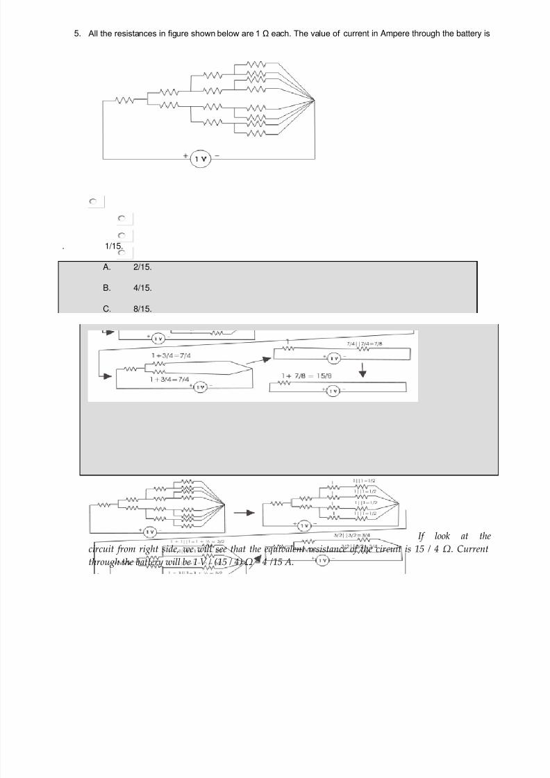
7/21/2019 Objective Questions Electrical Engineering.pdf
http://slidepdf.com/reader/full/objective-questions-electrical-engineeringpdf 144/150
5. All the resistances in figure shown below are 1 Ω each. The value of current in Ampere through the battery is
.
1/15.
A. 2/15.
B. 4/15.
C. 8/15.
If look at thecircuit from right side, we will see that the equivalent resistance of the circuit is 15 / 4 Ω. Currentthrough the battery will be 1 V / (15 / 4) Ω = 4 /15 A.

7/21/2019 Objective Questions Electrical Engineering.pdf
http://slidepdf.com/reader/full/objective-questions-electrical-engineeringpdf 145/150
6. Two wires A and B of same material and length l and 2l have radius r and 2r respectively. The ratio of theirspecific resistance will be
. 1 : 4.
A. 1 : 2.
B. 1 : 1.
C.
1 : 8.
The resistivity of any substance depends upon its material not upon its dimensions.
7. If the length of a wire of resistance R is uniformly stretched n times its original value, its new resistance is
. n.R.
A. n2.R.
B.
R/n.
C. R/n2.
Let's cross-section of the wire is A = πr2 , length of the wire is l therefore volume of the wire is A.l. Nowif the length of the wire is stretched to n times of its original length i.e. now length of the wire becomes l'= n.l. Now if r' is the new radius of the cross-section of the wire then new cross-sectional area A' = πr'2
If the volume of the wire is same before and after stretching, A.l = A'.l' ⇒ πr'2.n.l = πr2.l ⇒ r'2 = r2/n ⇒
πr'2 = πr2/n ⇒ A' = A/n. Thus resistance of the wire after stretched is ρ(l'/A')= ρn.l/(A/n) = n2ρ(l/A) =
n2.R.
8. The resistance between the opposite faces of 1 m cube is found to be 1 Ω. If its length is increased to 2 mwith its volume remaining the same, then its resistance between the opposite faces along its length is
. 1 Ω.
A. 2 Ω.
B. 4 Ω.
C.
8 Ω.
Volume = lengthXarea so if length is increased by 2 times then area will be decreased by 1/2, if resistanceR = ρ(l/A) = 1 Ω ⇒ R' = ρ(2l/0.5A) = 4ρ(l/A) = 4R = 4 Ω.
9. A wire of length l and of circular cross - section of radius r has a resistance of R ohms. Another wire of samematerial and of x-section radius 2r will have the same R if the length is
. 2l.

7/21/2019 Objective Questions Electrical Engineering.pdf
http://slidepdf.com/reader/full/objective-questions-electrical-engineeringpdf 146/150
A. l/2.
B. l2.
C. 4l.
The cross-section of the first wire is πr2
. The cross-section of the second wire is π(2r)2
= 4πr2
. Theresistance of any wire depends upon the ratio of its length to area. So if the cross-section of the secondwire is 4 times of that of first wire, the length of the second wire must also be 4 times of that of first if theresistance of both wires are same.
10. The insulation resistance of a cable of 10 km is 1 MΩ. For a length of 100 km of the same cable, theinsulation resistance will be
. 1 MΩ.
A. 0.1 MΩ.
B. 10 MΩ.
C. 0.01 MΩ.
Conductor resistance is directly proportional to length. But insulation resistance is the resistance to the flow of leakage current to ground. Since the flow of leakage current is directly proportional to the lengthof the conductor as because with length conductor inner and outer surface are of the insulation layer ofthe conductor increases. So insulation resistance is inversely proportional to the length of conductor.
11. The hot resistance of the filament of a bulb is higher than the cold resistance because the temperaturecoefficient of the filament is >
. positive.
A. negative.
B. zero.
C. infinite.
Positive temperature coefficient refers to materials that experience an increase in electrical resistancewhen their temperature is raised.
12. The temperature coefficient of resistance of an insulator is
positive and independent of temperature.
A. negative and dependent on temperature.

7/21/2019 Objective Questions Electrical Engineering.pdf
http://slidepdf.com/reader/full/objective-questions-electrical-engineeringpdf 147/150
B. negative and independent on temperature.
C. positive and dependent on temperature.
.
13.
Four resistances 80 Ω, 50 Ω, 25 Ω and R are connected in parallel. Current through 25 Ω resistance is 4 A.Total current of the supply is 10 A. The value of R will be
36.36 Ω.
A. 66.66 Ω.
B. 40.25 Ω.
C. 76.56 Ω.
The currentthrough 25 Ω resistor is 4 A hence voltage across it is 4X25 = 100 V and this is the voltage across the
supply as well as other resistors. hence current through 50 Ω and 80 Ω resistors will be 100/50 = 2Aand 100/8 = 1.25 A. Therefore current through R x will be 10 - 4 - 2 - 1.25 = 2.75 A and then Rx =100/2.75 = 36.36 Ω
14. Three parallel resistive branches are connected across a DC supply. What will be the ratio of the branchcurrent I1:I1:I1 if the branch resistances are in the ratio R1:R2:R3 :: 2:4:6
6:4:2.
A. 6:3:2.

7/21/2019 Objective Questions Electrical Engineering.pdf
http://slidepdf.com/reader/full/objective-questions-electrical-engineeringpdf 148/150
B. 2:4:6.
C. 3:2:6.
Current is inversely proportional to resistance. Then 1/2:1/4:1/6=3:3/2:1=6:3:2.
15.
Two resistors R1 and R2 given combined resistance of 4.5 Ω when in series and 1 Ω when in parallel, theresistance are
1.5 Ω and 3 Ω.
A. 2 Ω and 2.5 Ω.
B. 1 Ω and 3.5 Ω.
C. 4 Ω and 0.5 Ω.
When in seriesR1 + R2 = 4.5...........(1)when in paralle(R1*R2)/(R1 + R2) = 1(R1*R2)/4.5 = 1R1*R2 = 4.5..........(2)COMBINING (1) AND (2),WE GETR1 = 1.5 or 3 and R2 = 3 or 1.5
16.
When a resistor R is connected to a current source, it consumes a power of 18 W. When the same R isconnected to a voltage source having the same magnitude as the current source, the power absorbed by Ris 4.5 W. The magnitude of the current source and the value of R are
√18 A and 1 Ω.
A. 1 A and 18 Ω.
B. 3 A and 2 Ω.
C. 6 A and 0.5 Ω.
For resistance R, connected to the current source, the consumed power is 18w i.e 18 = I 2R (1) and forsecond condition 4.5 = V 2/R (2) and current and voltage having same magnitude that is V = I (3).By solving these 3 equations we get R = 2 ohms and I = 3 A

7/21/2019 Objective Questions Electrical Engineering.pdf
http://slidepdf.com/reader/full/objective-questions-electrical-engineeringpdf 149/150
17. When all the resistances in the circuit are of 1 Ω each, the equivalent resistance across the points A and Bwill be
.
1 Ω.
A. 0.5 Ω.
B. 1.5 Ω.
C. 2 Ω.
All the resistances are same. There is no potential difference between central vertical resistance [likeWheatstone Bridge], so it can be imagined that it is opened. Then the equivalent resistance between A &
B is Req = (1+1) || (1+1) || 1 ΩReq = 2 || 2 || 1 ΩReq = 0.5 Ω
18. Resistivity of metals is expressed in terms of
μ Ω.
A. μ Ω - cm ⁄ °C.
B.
μ Ω - cm.
C. μ Ω. 19. Resistivity of copper is of the order of
17.2 μ ohm-cm.
A. 1.72 μ ohm-cm.
B. 0.172 μ ohm-cm.

7/21/2019 Objective Questions Electrical Engineering.pdf
http://slidepdf.com/reader/full/objective-questions-electrical-engineeringpdf 150/150
C. 172 μ ohm-cm.20. Resistivity of copper at absolute zero is
3.12 μ ohm-cm.
A. 1.56 μ ohm-cm.
B.
negligibly small.C. 6.62 μ ohm-cm.
The resistivity of copper does not vanish at absolute zero. Instead, its level at absolute zero is known asthe residual resistance. Copper has a residual resistance of 0.020 nΩ m.
Related Documents