THIRD EDITIQN - - SERVICE MANUAL

Welcome message from author
This document is posted to help you gain knowledge. Please leave a comment to let me know what you think about it! Share it to your friends and learn new things together.
Transcript
THIRD EDITIQN - -
SERVICE MANUAL
(
OB-Xa PROGRAMMABLE POLYPHONIC SYNTHESIZER
--- ·----------------I . SERVI CE MANUAL
THIRD EDITION JUNE 1982 .
: :·::::I::: I::::.:~::::: I I::: I: I: I::::::::::~:: I I;::::·:: I: I: I . . : :
: Covering Units With Serial Numbers 820818 And Above
: I I::.::':·::: I: I:::: :·1::::: .: : : :-.·:: : :1: I:::: I: I::: I::: I::=: I::: I
TABLE OF CONTENTS ,.-~. ---- -------------------------------------------------------------
TECHNICAL NOTES - Specifications - Improvements and Additions - OB-Xa Software History - Test Procedure
Power SLtppl y Test Modulation Assembly Calibration Upper and Lower Control Board Calibration Voice Card Calibration
- The OB-Xa Diagnostic Eprom
THEORY OF OPERATION · - Cassette Interface - Computer Interface
CONNECTOR DIAGRAMS
SCHEMATICS
PARTS LAYOUT DIAGRAMS
PRINTED CIRCUIT COMPOSITE DIAGRAMS
ENGINEERING CHANGE ORDERS CECOs>
CORRECTION NOTICE (Business Reply Letter)
OBERHEIM ELECTRONICS, INC. 2250 So. Barrington Ave~
Los Angeles, CA 90064 USA
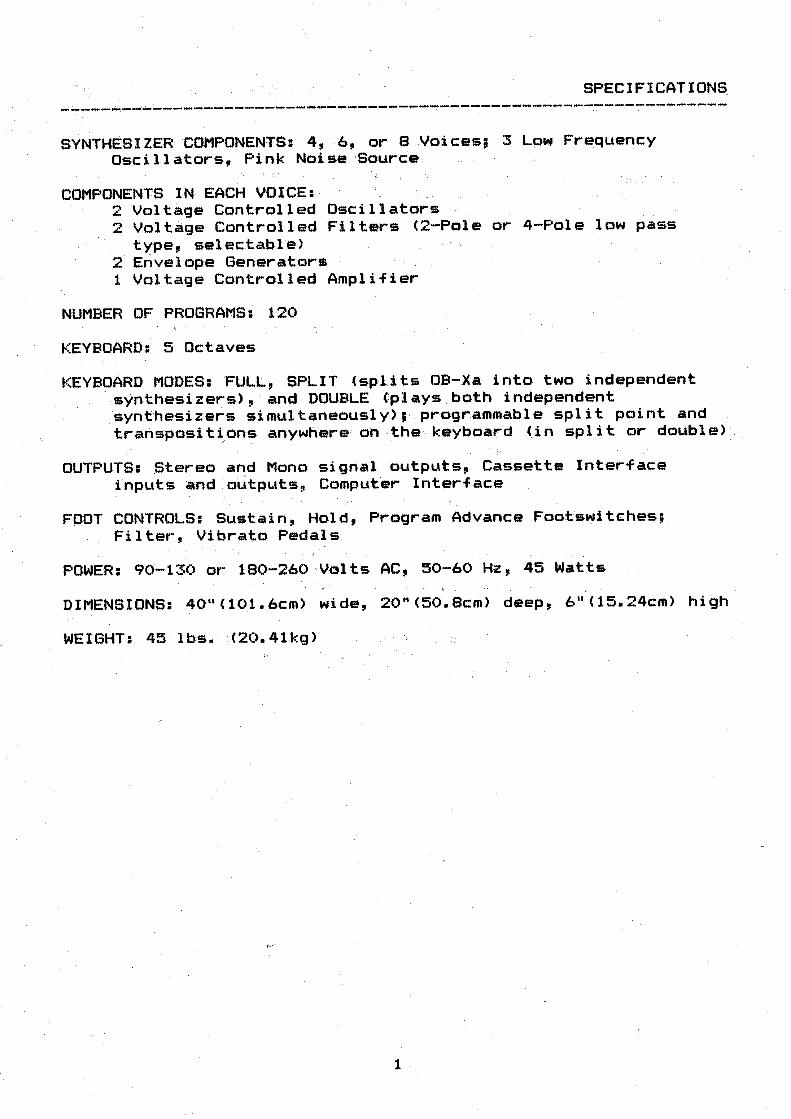
SPECIFICATION5_
·----- - --------- ---------------- ---- .-------------------------SYNTHESIZER .COMPONENTS: 4, . 6, or 8 .Voic::es; 3 Low Frequency
Oseillators, Pink Noise ·Source
COMPONENTS IN EACH VOICE1 2 Vciltage Controlled Oscillators 2 Voltage Controlled Filters <2-Pole or 4-Pole low pass
type, sel~ctable> 2 Envelope Generators 1 Voltage Controlled Amplifier
NUMBER OF PROGRAMS: 120
KEYBOARD: 5 Octaves
KEYBOARD MODES: FULL, SPLIT <splits OB-.Xa into two independent synthesizers>, and DOUBLE (plays . both independent ~ynthesizers simultaneously>1· programmable split point and t~ansposit~ons anywhere, on ·the keyboard (in split or . double>
OUTPUTS: Stereo and Mono signal outputs, Cassette Interface inputs and output~, Computer Interface
FOOT CONTROLS: Sustain, Hold, Program Advance Footswitches; Filter, Vibrato Pedals
POWER: 90-130 or 180-260 Volts AC, 50-60 Hz, 45 Watts ... ,
DIMENSIONS: 40" <101. 6cm) wide, 20" (50. Bern> deep, 6 11 < 15. 24cm) high
WEIGHT: 45- lbs. ·(20 .. 41kg)"
1 .

IMPROVEMENTS AND ADDITIONS -------- -- -------------------- . - · ----- ' -- . . . ------------------·---. -
Since its int~oduction in Janua~y 1981, the , OB-Xa has undergone a great many improvements and · additions. Since this manual is concerned with units with serial numbers of 820818 and above, only changes that have occured sinceFe.bruary 1982 are noted here. These units incorporate all of the earlier changes.
ECO #134: Changing two resistors on the Upper Control Board and one on the Lower Control Board reduces the volume of the NOISE function.
ECO #135: Changing U137 on the Upper Control Board from a. LM324 to a TL084 matches Filter Envelope characteristics between upper and lower trays.
ECO #136: Changing 2 resistors on each of the two Mother Boards increases the gain of the output. Changi·ng a resistor- on the Cassette Monitor Switch (rear paMel> raises ~he cassette monitor volume, keepiMg the ratio- cif the · ~olumes o~ _synthesizer output and cassett~ monitor constant.
ECO #140: This change i~plements software version XA-GAO. The change is made to eliminate an "edit doubling" effect in the first 11 8 11 software.
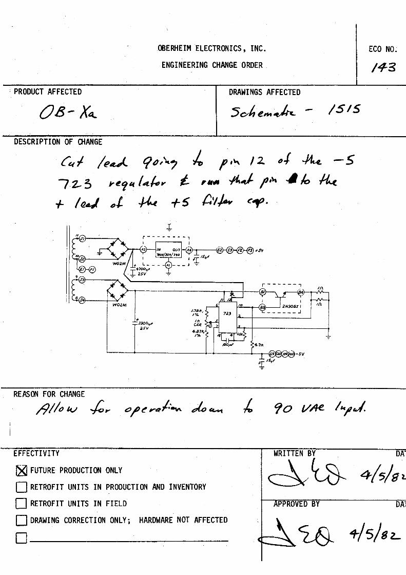
ECO #143: Cutting the lead going to pin #12 of the -5 723 regulator and' funning pin #12 ·to the -+ lead of the +5 filter capacitor allows for operation down to 90VAC input •
. The listing of the OB-Xa's Software History <next page) contains a brief discription of all of the major changes in the OB-Xa since its introduction.
2 ,
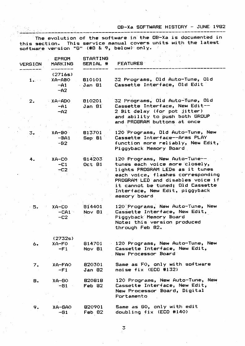
OB-Xa SOFTWARE HISTORY - JUNE· 1982
s . --- ---- ---- ----------- -------------------~ --------------
· The evolution of the software in the OB-Xa is documented in this section. This service manual covers units with the latest software version 11 6 11 (#8 & 9, belowJ , only.
VERSlON
1.
2.
3.
4.
5.
6.
7.
8.
9.
EPROM MARKING
(2716s) XA-ABO ·
..,A1 -A2
XA-ADO -Al -A2
XA--BO -BA1 -B2
XA-CO -Cl :-C2
XA-CO -CA1 -C2
(2732s) XA-FO
-Fl
XA-FAO -Fl
XA-GC> -61
XA-GAO -G1
STARTING SERIAL#
810101 Jan 81
.· 010201 Jan 81
81370i Sep· 81
'-'
'814203 Oct 81
814401 Nov 81
814701 Nov 81
820301 Jan 82
820818 Feb 82
820901 Feb 82
FEATURES . . ----------------- ·-----------------
32 Programs, Old Auto-Tune, Old Cassette Interface, Old Edit
32 Prog~ams~ Old Auto~Tune, Old Cassette Interface, New Edit--2 Bit delay (for pot jitter) and ability to pu~h both GROUP arid PROGRAM buttons ·at once
120 'Programs, Old Auto-Tune, New Cassette Interface~-Arms PLAY function more reliably, · New Edit, Piggyback Memory Board
120 Programs, New Aµto-Tune-tun~s e~ch voice more 'closely, lights PROGRAM LEDs as it tunes ~~ch voic~, flashes corresponding PROGRAM'- LED and disables voice if it cannot be tuned; Old Cassette Interface, New Edit, piggyback memory board
12o ~Programs; N~w Auto-Tune, New Casiette Interface, New Edit, Pitj~yback Memory Board Note: this version produced through Feb 82~
120 Programs, New Auto-Tune, New Cassette Interface, New Edit, New Processor Board
Same as FO, only with software noise fix <ECO #132)
120 Programs, New Auto-Tune, New Cassette Interface, New Edit, New Processor Board, Digital
. Portamento
Same as GO, only with edit doubling fix <ECO #140)
3
OB-Xa TEST PROCEDURE ·-- -~s-. _. · __ , -_:_. _~----- :""""~·-; _·· """:"'.· .· . -- - - ··- -- -_. --- .- ._ ------ -~------· ----·- · ---.· ----· ·--- ----
. . This following
Equipment
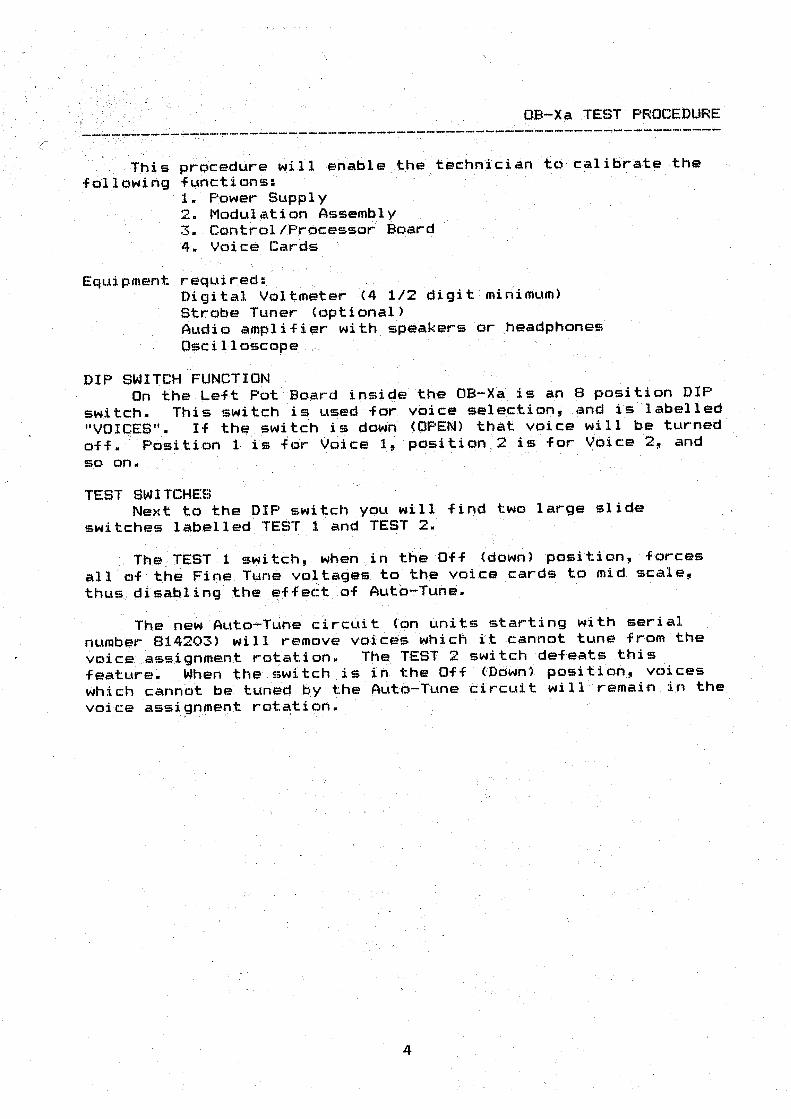
prqcedure will enable the techn~c:ian to ' calibra,te the functions: 1. Power Supply 2. Modulation Assembly 3. Control/Processor B_oard 4. Voice Cards
reqLti red: . Digital V~ltm~ter (4 1/2 digit ' mirii~um) Strobe Tuner <optional> Audio amplifier with . speakers or .headphones Oscilloscope
DIP SWI.TCH FUNCl)ON On the ~eft . Pot Board insige the OB-Xa. is an 8 position DIP
switch. This switch ·is used for voice selection, and is labelled "VOICES". If thf# swi,tch .is down <OPEN> that voice will be turned off. ' · Position 1- is f·or Voice 1, pgsition . 2 is for Voice 2, and so on.
TEST SWITCHES Next to the DIP switch you will find two large slide
switches labeiled· TEST 1 and TEST 2.
Th.e TEST 1 switch, when . in the' Off (down) position, forces all of t :he Fine. Tune voltages. to the voice cards to mid sc,-ale, thus_. disabling the ~ffec:t ·of Auto-Tune.
Th~ ne~ Auto-Tun• circuit (6n units starting with serial number 814203) will remove voic:e'is which it cannot tune from the
voice ... assignment ro-t;ation. Thf:! TEST 2 switch defeats this feature. When the switch is iri the Off tD6wn1 position, voices which cann6t be turi~~ by the Auto-Tune ~~rcuit will remain in the voice assignment rot~tion.
;.- - . .. - ';._
4
POWER SUPPLY TEST ---------------------. - - --- .-__ ' _,,..;·~ ~--~- --- }. ' --.. · . -... - ' '. ·' . . . 0 - - , .~ ------
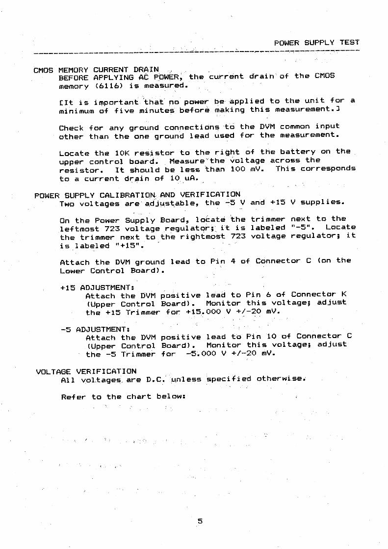
CMOS MEMORY CURRENT DR~ l N. .·, . . BEFORE APPLYING AC POWER; the· current draih of the CMOS memory (6116) is measured. ·
Cit is importan~\~at· ~o power be ~pplied to the unit for a
minimum of five minute~ befor~ ~aking this measurement.]
Check for any ground connections ·t6 the DVM common input
other than the one ground lead used . for the measurement.
Locate the 10K resistor to the right of the battery on the
upper control boar~. Measure ~t~e ~oltage across the resistor. It should be less than· 100 mV. This corresponds to a current drain . of 10 uA.
, .. - , . ... }
POWER SUPPLY CALIBRATION. AND VERIFICATION . Two voltages are ·acfjµ_st.able, the -5 V and +15 V supplies.
On the Power Supply ~card, lo~at~ ~he trimmer next to the
leftmost 723 voltage _re.gulatqr; : it is labeled 11 -5 11• Locate
the trimmer next to , the rightmost 723 voltage regulator; it is labeled "+15".
Attach the DVM ground lead to Piri 4 of Connector C (on the Lower Control Board).
+15 ADJUSTMENT: Attach the DVM ~o~itive lead to Pin 6 of Connector K <Upper Control Board). Monitor this voltage; adjust the +15 Trimmer for +15 .• 000 V +/-20 mV.
-5 ADJUSTMENT: . Attach the DVM positive lead to Pin 10 of Connector C <Upper Control Board>. Monitor this voltage; adjust
· the -5 T~immer for -5.000 V +/-20 mV.
VOLTAGE VERIFICATION All yoL.tage~ are D.C .• . unle~s '.specified otherwise.'
Refer to the chart below:
5

·. CONTROL BOARD, Uppei:- and Lower, Connectors K & A,
respectively:
PIN # · VOLTAG.E TOLERANCE . - . - .
-----.--------. -------------1 "'5. 5 VAC +/-2 V 2 +5.0 V +/-250 mV 3 +5.0 V · +/-250 niv 4 key 5 +15.0 V +/-20 mV 6 -+:15.0 V +/-20 mV 7 gnd 8 gnd 9 ..:. 15. 0 V +'/-750 mV 10 -15.0 V .. ' +/-750 mV
MOTHER BOARD, Upper and Lower, Connector 0:.
PII\I # .. VOLTAGE TOLE.RANCE ; . .. .
------ ----- ------0- ·-- - .· 1 - 15.0 V +/-750 mV 4, key
. 3 +15.0 V . · +/....;20- mV
4 +15.0 V +/;...20 mV 5 gnd 6 gnd 7 gnd 8 gnd 9 - 5.0 V +/-20 mV 1(> -5.0 V +/-20 mV
UPPER CONTROL; BOARD VOLTAGE VERIFICATION '·
Verify the +5.6 V supply at Pin 16 of l.C. #145 <4051>,
tol•rance is . +/-200 mV.
Verify the -10. V supply at pin 7 of I.C~ #1.49 (4053),
tolerance is +/-1 V.
LOWER CONTROL BOARD .VOLTAGE VERIFICATION Verify the +5.6 V supply af Piri 16 of I ~t. #45 (4051>,
tolerance is +/-200 mV.
Verify the -10 V supply at pin 7 of I.e. #13 (4053>,
tolerance is +/-1 V.
POT BOARD VOLTAGE VERIFICATION Two voltages are developed on the Pot Board, +5.6 V and
-5.0 v. Verify the +5.6 V supply at Pin 16 of r.c~ #5 on the Pot
Board • . Tolerance is +/-350 mV~
Verify the- -5.0 V supply at pin 7 of I.C. #5. Tolerance is
+/-500 mV.
6

MODULAT l,ON -ASSEMBL v. CAL I BRAT I ON -----· -------------~------- .------~-d(- ' ----... . _________ , __________ _
Below are two methods of, modulati'On .assembly calibration:
.the first utilizes~ DVM, and the second is an audio method that
does not use a DVM.
Locate the trimmers which are accessible through· the holes
on the top of the Bend Assembly. Refer to the "Trimmer Location
Diagram" for locations.
All switches -on the .Bend Assembly should be off <LED out>,
except the "Down Transpose" and "Lower & Upper" switches.
CALIBRATION WITH DVM
1- Center Lever Adjustment The Center Lever adju·stment· .needs to. be performed only if
the "Up or Down Eeend" cannot be brought into range, i.e.,
will not bend an octave.
Measure the voltage·- at Pin 1 of. · IC tta., Adjust the "Center
-Lever" -trimmer for 0.000 V +/-25 mV.
2- Bend Offset Adjustment Tbe bend offset adjustment nseds to be performed only if
there is excessive beating between - the two oscillators when
"DSC 2 ONLY" is pressed. Do the following:
Hold note CS, press "AUTO" to autotune the oscillators,
be sure the Oscillators are beatless (less than 1 beat
per second>, press "OSC 2 ONLY" swi .tch (LED on>.
Adjust the "Bend Offset" trimmer until the beating is
less than 1 beat per second.
If IC #8 has been replaced, the -following calibration
pro~edure is used:
Measure . the voltage at Pin 1 of -IC #8. Adjust the
, "Center Bend" trimmer for 0.000 V +/-25 mV.
Measure the voltage at Pin 7 of IC #8. Adjust the
"Bend Offset" trimmer for 0.000 V +/-2 mV.
Measure the voltage at Pin 10 of Connector C. This voltage,
which should be 0.000 V +/-20 mV, is the bend circuit offset
voltage. This voltage must be added to <or subracted from> the
voltages stated for the following three adjustments:
3- Up Bend Adjustment: Move the bend lever fully towards the front of the unit.
Monitor the voltage at Pin 10 of Connector C (Lower Control
Board). Adjust the "Up Bend" trimmer until the voltage is
-1.000 V +/-2 mV (+/- the bend circuit offset).
7
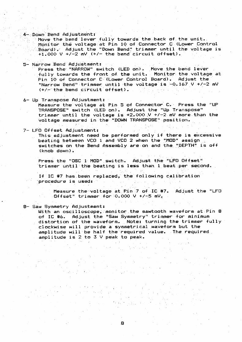
) ~,... ·Down Bend Adjt;.\Stment; ·_.'-- , "' Movethe 'bend "' lever· fully towards the back of.the unit • .
_Monitor- the val tage . at Pin 10 of ,-Connector C <Lower .Control -Board>.· - Adjust ·the "Down Bend '..' trinuner:- until the vol tage is _ +i.ooc:> V +/-2 mV (+/~ the bend circuit offset>. ·
5- Narrow Bend AdjListment: , F;ress the' 11 NARROW 11 switch · (LED on).. Move :the bend l~ver
. . . fully towards t!"le front of the unit. ttof1j.tor the vol t~ge at Pin 10 of Conne~tor C (,Lower Control Board). Adjust the "Narrow Bend" ~tri.mmer until the voltage is --0.167 V +/-2 mV (+/~the behd ~i~ cuit offset).
6- Up Transpose Adjustment: Measure the voltage at Pin 5 of . Connector c~ Press t h e " UP TRANSPOSE" switch <LED on). Adjust the "Up Transpose" trimmer until the voltage is +2.00QV +1.._..2 mV more than the volta<;;Je measured in the "DOWN TRANSPOSE:'' .position.. · ·
7- LFO Offset Adjustment: This adjustment need be performed only if there is e x cessive beating between VCO 1 and YCO 2 when the "MOD" assign switches on the Bend Ass~mbly are on and th~. ·~DEPTH~ __ i s off < knob down> •
Press the "DSC 1 MOD'' switch. Ad,ju.st the '.'LFO Offset '; · trimmer unti 1 '· the beating is le$$ ·t-hah. 1 b.eat per second.
If IC #7 has been replaced, the following calibratio~ ·procedure i ~ used: -· ;
;~
Measure ,the-'·vol tage at Pin 7 of IC #7 • . - Adj_ust the "LFO Offset" trimmer for :0.000 v · +/-5 mV~
8- Saw Symmetry Adjustment: With an osc:il'loscope, : monitor.: , the sawtooth w~veform at Pin 8 of lC #6. Adjust the IISaw Symmetry" trimmer fe>r minimum distortion of the waveform. Note: turning the trimmer fully clockwise wi 11 provide a symmetri.cal waveform but- the amplitud~- will -be half the required value. The required amplitude is 2 to 3 V peak to peak.

AUD IO METHOD · FOR MODULA TI ON AS~~MBL Y .. C~L I BRAT I ON . ' ~ , . . ' . . . ' . - ' . .... : . ' : ' -, · .. ~ - __ , " ' .
Locate the trimmers which -are. accesl.iiible. ,th~qugh the. ho.ies
on the top of the Bend Assembly • . : :Refer .. to the /'. Tri'mmer Location Diagram11 for locations. · ' ·
. '
Al 1 switches ·on the Bend Assemb:Ly . should. be · off <LED out>,
except the 11 D0wnTranspose 11 · and · 11 Lower & Upper" $witches.
1- Center Lever Adjustment The Center Lever adjustm~nt needs to be performed only if
the "Up or Down Bend" cannot be brought: into ran.g_e!I i.e.,
wi 11 not bend· an octave. ···
Ho1 d note ' C5, · press "AUTO" to.: autjjtl.lfl~ the psci l lators, be
sure the Osei 11 ators are beatl ess U ess than 1 beat,/ per
second) .• · Press the "NARROW"_ switch. Adjust the "Center
Lever 11 trimmer so that ·pressing the "NARROW" switch on and
off causes · no · change in pi toh .•
NOTE: Adjustment of the "Center Lev.er" trimmer . wit.hout a
DVM may cause the center of the "MASTER . TUNE" contr'ol on · the
·front · panel to be flat or ' sharp of .. --A:;::440. . We recommend
adjus·ti ng the "Genter Bend'' tr 1·mmer.: only i -f . necessary. ·", ; · ,, . .
2- Bend Off set Adjt.lstment . THe bend ·offset adju~tment needs to ~e performed onli if
there is· e~-: cessi ve· beating b.etween the two , osc;: i 11 a tors when
"OSC 2 ONLY" is pressed. Do the following:
Hold note C5, press "AUTO" to autotune the oscillators, be sure the Oscillators are beatless (less than 1 beat
per second), press "DSC 2 ONLY 11 switch <LED on).
Adjust the "Bend Offset" trimmer until the beating is less than 1 beat per second.
3- Up Bend Adjustment: Turn on the "OSC 2 ONLY" (LED on>, and- make sure the NARROW
switch is off <LED off). Hold note C5, press "AUTO" to
autotune the oscillators, be sure the Oscillators are
beatless (less than 1 beat per second). Move the bend lever
fully towards the front of the unit. Adjust the "Up Bend"
trimmer until the interval between DSC 1 and DSC 2 is
exactly One Octave.
4- Down Bend Adjustment: Move the bend lever fully towards the back of the unit • .
Adjust the "Down Bend" trimmer until the interval between
DSC 1 and DSC 2 is exactly One Octave.
9

~- 'Narrbw Bend -Adjustment; Pr~:ss t.he "NARROW" .· switch <LED on>. ·· Move the bend .lever
fully. towards the,? front of the unit. Adjust the "Narrow
Betid" trimmer unti.l inter Val between OSC- 1. · and OSC 2 is exactly a Major Second <whole step).
6·- Up Transpose Adjustment: . ·Press the ''UP TRANSPOSE'; · switch -<LED on) •. Adjus-t the "U,p_
Transpose" trimmer until the interval bet~een · th.e IIUP
TRANSPOSE" and the "DOWN TRANSPOSE" positions is exactfy Two
Octaves.
7- LFO Offset Adjustment: This adjustment need be performed only ' if there is excessive
beating t:>etween VCO 1 ~nc:I VCO 2 when the "MOD" assign
switc:hes on the Bend Assembly are ·6n and the "DEPTH" is off
( knob down) • .
Press the 0 0SC 1 MOD" switch. ' AdJust the "LFO Offset"
trimmer until the beating is less than 1 beat per. second.
a- Saw Symmetry Adjustment: Pull up the "RATE11 knob on the modulati,on panel. This will
select a Sawtooth wave frofll the Hodulatiqn Assembly. Set the
"RATE" knob to approxi,m.ately' 9 o:oclock. PUll up the . IIDEPTH" knob
and turn the knob all th• way up. Play and hold a -note. Adjust
the "Saw Symmetry'.' tri,mmer until the wavf:!for.m is one, smooth
Sawtooth wave. Note: turnin-g the trimm.er fully clockwise will provide
a symmetrical waveform but the ampl i tt..tde wi 11 be too low.
10
UPPER AND .. -LOWER .-CONTROL BOARD CALIBRATION .. - . .• ·. -: . ~ .- .
- ·--------- - · '---- . ----- .. ·- . ~~ - ' - . ~ ... . . ----. ' -~- --.------- . ·- -, . -----. , ;,: ' ' " . . · .: ·i : . . .· " , · .
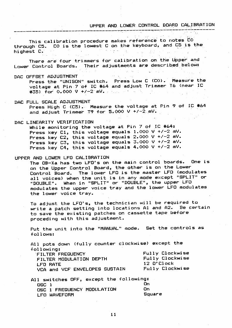
This calibration procedure makes refer~nc~· to notes to· through C5. highest C.
CO is the l ,owest C on t;he keyboard, and S.5 i~ the
. '
There are four trimmers for calibra:tion on. the Upper and
Lower Control 'Boards. Their adjustments ar,e describ._ed b·elow:
DAC OFFSET ADJUSTMENT Press the "UNISON" switch. Press Low C (CO). Measure the voltage at Pin -7 of IC #64 and adjust Tr~mmer T6 <near IC #35), for O. 000 :(J +1-2 · mV.
DAC FULL SCALE ADJUSTMENT Pre~s High C CC5)~ Measure . th~ voltage at Pin 9 of IC #64 and adjLlst Tri'-mmer Tq for 5. 000 V +/..,..2 , mY~
DAC LINEARITY VERIFICATION While monitoring the voltage at Pin 7 of IC #64: Press key Cl, this voltage equals 1.000 V +/-2 mV. Press key C2, this voltage equals 2.000 V +/-2 mV. Press key C3, this voltage equals 3.000 V +/-2 mV. Press key C4, this voltage equals 4.000 V +/-2 mV.
UPPER AND LOWER LFO CALIBRATION The OB-Xa has two LFO's on the main control boards. One is
on the Upper Control Board, the other is on the Lower Control Board. The lower LFO is the master LFO (modulates
all voices) when the unit is in any mode e>:cept "SPLIT" or "DOUBLE". When in "SPLIT" or "DOUBLE", the upper LFO modulates the upper voice tray and the lower LFO modulates
the lower voice tray.
To adjust the LFO's, the technician will be required to write a patch setting into locations Al and A2. Be certain to s~ve the existing patches on cassette tape before preceding with this adjustment.
Put the unit into the "MANUAL" mode. Set the controls as follows:
All pots down (fully counter clockwise> except the following:
'FILTER FREQUENCY FILTER MODULATION DEPTH LFO RATE VCA and VCF ENVELOPES SUSTAIN
Fully Clockwise Fully Clockwise 12 O'Clock Fully Clockwise
All switches OFF, osc 1
except the following:
OSC 1· FREQUENCY LFO WAVEFORM
MODULATION
11
On On Square
(_ Write the above patch into me111ory locations Al and A2. See
the oa~xa Own-r's M~nual (Pag~ 3- Writing~ Program>, for a
description of this proc:edure.
Press "SPLIT". The synthesizer' will enter the Split l"lode.
The keyboard will be split at note C2. Program Al will be
on the lower half of the keyboard and program A2 will be on
the upper · half. Note: The synthesi ze'r will be split with . ' . . ( . . ' - ' .
these programs upon power' up. If the Split or Double modes
have been previously entered, the synthesizer will remember
the split point and programs previously rec:alled~
Hcild note Cl and whil~ liste~ing to the oscillator being
modulated, adjust Trimmer T5 <Lower Board) for a LFO rate of
2-4 Hz.
Hold note C2 and while listening to the oscillator being
modulated, adjust the trimmer on the ·u~~er Board <near IC
#148) for a LFO rate of 2-4 Hz.
12
VOICE CARD CALIBRATION --- · . ______ _ · ------- ... ----- "· .. .. - . -- ! ... _ ~ : --- . - ~'>~+ .... - ~ -· . __ , -- ·- ~ ~ .... -~-----
,; The,, foJlowing equip}nent is,· req1..,ir-ed fdt" calibrating -the, voice cards in ·the OB-Xa: . ·' . ·. , ' ,, · · · ·, , . ,
Audio a~plifier with speakers or headphones '''Mini to Mini jumper ·c1tp Oscil~oscope (9~tional>
The.re are .15 Trim~~rs on the OB--Xa voic:'e ";:card f 'or : . . .. , . . . '
calibration. They are:
T1 VCOl Volts Per Octave 'T2 VC'o1 High Track T3 . VCOl Initial Frequency
:T4 VCOl Pul-~ Width TS T6 T7 TB T9 TlO TJl '
. Tl;2 ·r1~ T14 r1~
VC02 Volts P6r O~tave vcp2 High _Track ~CO2 irtitial -~requency · · VC02 Pulse Width Filter Envelope Modulation filter Resonance · Fi 1 ter · Vol ts Per Oct.ave (4:.,;;PoNii!> Fiit~r Volts ' Per O~tave· <2~Pole)
· ~ilter I~itial Fr~que~cy C4~Polel Fi 1 ter Initial · Fre!quen'cy (both f i 1 ters> VCA Offset
OSCILLATOR TUNING <VCO's)
1. Pl.tt. the unit into . the1 11 MANUAL II mode. Set the controls as foll9ws:
All pots down (fuJly co~nter cluckwise> except the following:
FLL T.ER FREQUENCY . FILTER MODULATidN
VCA and VCF ENVELOPES SUSTA'lN MASTER TUNE VC02 DETUNE
Ful·l y Clockwi~se , Fully Cl oc kwi se
Fl.tfl y C1 bckwi se 12 O'Clock (dead zone) 1'2 O'Clock ,.·.(LED out)
All switches OFF, except the followin4~
DSC 1 OSC 1 WAVEFORM TRACI< TRANSPOSE <on bend assembly>
On Pulse On Down Octave
2. Lift the front panel. Watch the LEDs on the voice cards. Play C5 repeatedly until Voice 1 is playing and press "HOLD". (This is for ref-erence>.
13
3. Using the voice selection DIP switch, turn off all of the · voices eHcept 1 and 2. Pl.ay C5. You shauld ·now hear Voice
1 Osc· 1, . and Voic.e 2 Osc 1. ·. Pres? Auto-T1.me. If the two osci1 latbrs are not in tune~ the init'ial. frequ~ncy of one or both needs to be calibrated. · Turn off the TEST! switch Cdownl. Adjust Trimmer T3 for no beats. Turn on the TEST! switch · once again. Pre5s Auto-T.Lme aric:i make 'sure that there are still no beats.
4. Play C3 and listen for beats. Turn the Volts per Octave trimmer <Tl for VCOl> further out of tune unti 1 there are double the amount of beats per second. -
,· 5. Press Auto-Tune, play CS, and make sure the oscillators are
still in tune.
' 6. Repeat steps 4 and 5 until tuning is satisfactory.
7. Repeat steps 3 through 6 for · al1 ' voices.
HIGH-TRACt< ADJUSTMENT Set the TRANSPOSE switch on the Bend . Assembly "UP OCTAVE". Verify the "Tr.anspose~' c'·ircuit is within specifi.cation <see the section on "Modulation Assembly Calibration">. All other switches and po~s stay the same.
Holding note cs, turn the "High Track" Trimmer <T2> until no beats are heard.
USING A STROBE TUNER FOR OSCILLATOR CALIBRATION Using a strobe tuner will res.ult in the oscillators being tuned more accurate! y. '. To us~ a strobe tuner for measuring the pitch of the oscillator$ follow the above procedure, turning only the voice card being calibrated on. Plug the tuner into the a(,di o output <use the MONO output>.
Playing Cl on the keyboard should make the fi~st octave scale appear st:ationary on the strobe tuner. C2 will make the second octave .seal e stop, and .· so on., .
It recommended that only one voice be calibrated with the strobe tuner and that this voice then be used as a reference for tuning the other oscill~tors.
14
PULSE WIDTH CALIBRATION With th~ DIP switch, turn only the voice to be calibrated
on. Press n·ote· C3 and adjust the 11 P1.11'se Width" tri.mmer (T4>
for · the most 11 hol'low" sound.·
If an oscillos.cope is being used, monitor the output of · the
voice . card at Pin 2 of Connector G. Adjust the "Pulse
Width" trimmers for a 50'Y. duty cycle.. ·
Repeat the above VCO calibration for VC02. Turn VC01 off
and turn VC02 on.
ENVELOPE MODULATION CALIBRATION Put the unit into the ' 11 MANUAL 11 mode. S~t the controls as
follows:
All pots down (fully tounter clockwise> except the
following: '
FILTER FREQUENCY FILTER MODULATION VCA and VCF ENVELOPES SUSTAIN MASTER TUNE VC02 DETUNE
Fi..111 y Clockwise Fully Clockwise · Fully Clockwise 12 O'Clock (dead zone> 12 O'Clock <LED out)
All switches OFF, except the following:
DSC '1 DSC 2 F-ENV TRACI< TRANSPOSE Con bend as•embly)
On On On On Down , Octave
Using the DIP switth~ turn on only the voice to be
calibrated.
While listening to both oscillators, adjust the F-ENV
tri~mer CT9) until VCO 2 is exactly One Octave ~bove VCO 1.
-15
FIL.:TER CALIBRATION ~ . :' '. . ,. .. . .
To ·t:a..l i brate the filter, it· 4,s . r:,ec;e~s~ry, t;o calibrate one
voice as a reference, and then cal j br.ate , 1;Q~L pt her voi c;es to that
reference.
FILTER REFERENCE CALIBRATION Using the voice selection DIP switch, turn- on the voice to
be used as a reference. .,
Put the unit into the "l1AN.UAl-" ioQde. Se.t the controls as
follows:
All pots down (fully .counter, clockwise> except the
following:
RESONANCE VCA and VCF ENVELOPES SUSTAIN . MASTER TUNE
Ful.l y Clockwise Fully Clockwise 12 O'Clock ~dead zone)
All switches OFF, except the following:.
NOISE TRACI< TRANSPOSE (on bend assemb)y>
INITIAL FREQUENCY CALIBRATION
On On Center Octave <LEDs off)
Playing note C3, alternate between NOISE and DSC 2 HALF.
Adjust the "Filter:- Initial Frequency'' Trimmer <T14), until
the pitch of the noise is the same pitch as VCO 2 • .
VOLTS PER OCTAVE CALIBRATION (VPO) <2- POLE> Playing note C2, again alternate between NOISE and DSC 2
HALF. · Adjust the IIFi l ter VPO," Trimmer (Tl2>, until the new
voice is the same pitch as the reference.
Reche~k the "Initial Frequencyll adjustment.
Playing note C4, again alternate between NOISE and DSC 2
HALF. Adjust the "Filter VPO" Trimmer <T12>, until the new
voice is the same pitch as the reference.
Recheck the "Initial Frequency" adjustment.
16

FILTER CALIBRATION WITH A REFERENCE U~ing th:e voice selection .DIP swi.tc;:h, turn on the voice to
be calibrated and the voice to be ·used ;as a ·referenc:e.
Put the u.nit into the 11 MANUAL 11 mode. Set the controls as
follows:
All pots down (fully counter clockwise) except the
following:
RESONANCE VCA and VCF ENVELOPES SUSTAIN MASTER TUNE
Fully Clockwise Fully Clockwise 12 0" Clock (dead · zone>
All · switches OFF, except the f?llowing:
NOISE · . TRA<:K.
TRANSPO~E Con bend assembl,y>
INITIAL FREQUENCY CALIBRATION
On on · Center Octave ' (LEDs off>
Playing note C3, alternate between the reference voice and
the _voice to be calibrated . Adjust the "Filter Initial
Fr,equency" Trimmer (Tl4>, until the new voice is the sa'me
pitch as · the ref~renc:e.' ' . . . . ' . .
VOLTS PER OCTAVE CALIBRATION <VPD> . <2-POLE>
Playing note C2, again alternate between the reference voice
"and th.e voice to .. be , calibr:ated. Adjust the "Fi 1 ter VP0 11
Trimmer <T12) , · until t,he riew voice is the same pitch as the
reference. ' .
Recheck the 11 In1tial Frequency 11 adjustment~
Playing note t4, again aiternate b~t~een the reference voice
and the voice to be calibrated. Adjust the "Filter VPD"
Trim~er <Tl2), until the new voice is th~ _same ~itch as the
reference.
RechecJ~ the .11 lni ti al Frequencyll a~just'!lent.
17
RE;:S'ONANCE CALl~RATION. .,,, .;-· - - '"i==·ut "-the unit into the ' 'iMANUALi• 'made. , Set the ' c::ohtr6i.'s as
f Ol·-1 ows: .~ -
Al 1 ·' pots d'own (-fully t:ountetr clock.wise> · ·exce,p1: -Jt:i·e · ;,.
following:
RESONANCE VCA ahd VCF ENVELOPES SUSTAIN MASTER TUNE
TRACI< TRANSPOSE <on bend assembly)
-- ;FtJl l y ·c1 ockwi se ' · Fully Clo2k~ls~ ~ 12 O'Clock_ (dead zone>
On --. ·Center Oc-ta've -< LEDs off>
Hold note C3 and listen to the_ voice card being Cc;llibrated.
Turn _ the IIResonanc~" trimmer (TH>> · up urti l . a low frequency
O·Sc:i:llation (approx. 500 Hz 'sine waief is. h~rd, · then turn
the trimmer back just to the point at .which the oscillation stops. . . r :,l _-- __ , .. a ' - _
. . , . .; If the above test fs questionable· cl'S 'to whether there' is
oscill·ation, ·monitor the ·output· of fhevoice at Connector 62
with an osci 11 osc::ope. Look for '·'an\i -osci lliiiti on w1 th "an amplitude greater th_an. __ 1C> mV.
4-POLE FILTER' CALIBRATION-.Press' th·e 114.:..POLE" ·swi tc::h~ Repeat the procedure · use·d for
- the 2-F'ole· fflter, : except 'u~e ·· t:i,e '11 4 ..:Pole Initial Frequency"
trimmer <T13) for initial frequency calibrati'oh, and the "4-
Pol e VPO'' trimmer (Tl 1 > for VPO calibration.
There is not a resonanc• adJU5tment for the 4-pole filter.
VCA OFFSET CALIBRATION P1..it the i.tnit i'hto the· ;,MANUAL II mode'~ . . Set th~ controls as
follows:
All pots down ' (full'y coun·ter c '.lo~lc:wise> except the
fol lowing:
VCA ENVELOPE SUSTAIN Fully Clockwise
All switches OFF.
Install a jumper on the card to be calibrated; see "VCA
Offset" diagram.
Press key C3. Turn the "VCA Offset" trimmer (T15) until a
minimum amplitude of the tone is heard.
18
THE OB-Xa DIAGNOSTIC EPROM . .. .
. --- ----- --------- ---------------- ---- ----------------- -----DESCRIPTION
'i :
··The diagnostic EPROM ccintains 5 subroutines" which e>tercise and
test v~rious portions of the logi~ and cbritr~l c~r~~1t~y on the
processor and control boards. Some tests, such as the sample/hold
staircase and the .latc:h ·test, merely exerc:ise ·a portion of the
circui try in ,a . spe«:ific manne.r and require t;he t:echnic:'i anto , observe
the ·operclti.on of that circuitry with an osci11Qscope while the test
is ·t:seing ·run.. Other tests, suc.h . as LED, perf odmeter, and ca\i.sette
routine, only require the technician . to ·observe the relevent LED to
determine whether the test was sucsessfut; . .- ~ ' ..
' ~-
When .the OB-Xa is initially tur~ed ori with a :diagnostf~ EPROM
installed, it starts running Test 1, which i~ indicated by the
illumination --of the PROGRAM 1 LED. Other· tests can be selected, in
any order, by .depressing the appropriate PROGRAM switch <1 through
5 only). When a test routi~e has finished ~ unning~ . th~ PROGRAM
switches are sampled to determine if any one i~ · dep~es~ed. If so~
the program· gcl>es to that · test r-outine; . if .no switch is depressed,
the pr·ogr-am again · runs the . r-outi n~ it just completed. The net
effe~t of this procedure is th.at a test routine· is run repeatedly
i.mti 1 another : .test · is sel.ected.
The diagnostic EPROM is inserted in the socket for EPROM 0
(loca~ ion A104). EPROMs 1 and 2 may be e i ther in the system or
not; they have no effect on the diagnostic program ~
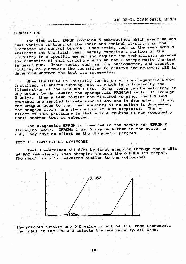
TEST 1 -- ·SAMPLE/HOLD STAIRCASE;
Test- 1 exer cises al 1 S/Hs by first. steppii)g through the 6 LSBs
of · OAC t 64 steps> , , then .teppi ng through the:? 6 ~SBs (64 steps).
T'he re·sult os a S/H wavef,orm si mi 1 ar to , the following:
The p r ogram outputs one DAC value to all 64 SIH, then increments
the input to ·the DAC and outputs the ,new value to all S/Hs.
19
' ., All S/H outputs which go off the board should be observed at
the connector in order to maximize the amount of circuitty ~nd
boar·d tested. Those S/Hs which a.re used internally on tJ,e p:mtrol
board must be observed at the S/H output. It should be·,;:real i zed
that · the ATTACl<, . DECAY, and .RELEASE signals.for both the filter a.nd
the amplifierenvelop!es <""-FAn( ~ LAATk, _L..FD.CY, LADC::Y·; · LFREL, LAREL
for. the ·. lower. . cortrc;,l, UFATK, ·uAATK, UF.Dt;:?';;: UAJ?CY, ·tJF~EL ; UAREL for
the 1-1pper> ,. as wel 1. a.s t _he K:EYCV si,gnal s . w_i 11 . • hot t::onf orm to the
wavefor-m shown above .• · Tt:,e envelope par'ameters· w_il_l ·: e>:hib-it' a ·
wa.veshf:\pe inverted, from that, ~hown above and wi fl ·vary frofo ground
to about ..,2~0mv. . ln ur,its wi thoLit digi'tai portamento, · the l<EYCV
., wavefqrm at the connector will appear ' rounded and wi l i fevel' off ·at about 2 volts. The reason for thi.s distortion 11:? 'tha't the ·
portamento CV (LPORTCV, UPORTCV> f s incr~a-~ng at ·the ~ame tlme as
the ~<EYCVs. , Thus, ~t th~ high end of the range the portamento CV
is high enough to prevent th,e KEYCV? ' from changing ' within ' the time between, DSC increments. · · ' · · · · · · ·
: .; / . '
TEST 2 - .LED LATCHES A.ND LAMPS . ,~. :
This routine tur;-ns on ali o-F the . fr'oM!t panel LEDs, except "for • j ' • · - . ' . ; _ •
the cassette . and bend .box L.EDs which must be turned on manLial l y. A
sucessf ul test is determined jj'y vi'sual ly ,obsen;,i ng :that all the
LEDs are illuminated. Since this is ·'test '·:i, ' thei 'PROGRAM 2 LED wHl
flashes.
TEST 3 - PERIODMETER
This test checks the periodmeter for the ·autotune circuit.
However, this periodmeter test is designed to .test t~e original
autotune circuit in uni ts pefore serial numbei 8142'03 Csof tware
labelled XA~ABO, XA-ADO, and XA-Bpi : ·)t wiil not th.st the n~w
autotune circuit which sequences th~ P~bGRA~ ~LEDs as it tunes the
voices.
When "using Test 3 the CASSETTE ENABLE switch o'n . the rear panel
should be turned on, otherwise .the PROGRAM 3 LED will flash to ' . .
indicate that the test cannot b'e completed. Test 3 checks for a
sa~isfactory runri ~ng of the periodmeter constituted by Al23, A114,
A112, A104, A105, A113, A120, A121, A122, and A119 on the upper
control board, used during autotune t6 check the period of each
vco.
At the beginning of the test~ ' the PROGRAM 1 and 2 LEDs are
lit, the counter is reset, and an "all ones" condition is tested at
the output of the tri-st~te gates A11 2 , A~13, A105, and A104. The
counter is started arid · the dLttpt1t" is · ch~ c:::ked again after 655::::5
cl6ck pulses for an "all zeros" condition, except for the 3 LSBs
which are not taken into acc:~unt. ' rf tt1e 11~11 ones" or "all zeros"
conditions: fail on th~. 8 LSBs,. the_) PRPl3.RAM _l LED is turned off,
and if the "all ones" or "all zeros" condit i ons fail on the 8 MSBs,
the PROGRAM 2 LED is turned off. A suc cessful test is indicated by
the PROGRAM 1 and 2 LEDs in a steady on state.
2()
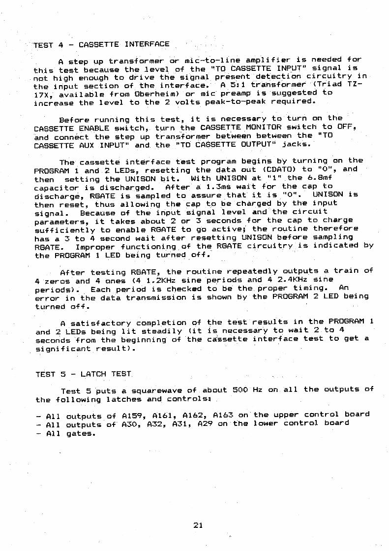
'TEST 4 - CASSETTE INTERFACE
A step up transformer ·or mic:-to-lfne amplifier is needed for
this test because the level of the . "TO CASSETTE I .NF'UT" signal is not high enough to drive th'e signal present 'detectfon circuitry in ' the input section of the iriter,face. · A ~;': 1· trahsformer · <Tr.iad TZ-
17X, available from Oberhei,n) ·or mic' preamp is suggested to . increase the level to ~he 2 volts peak-to-peak required.
Before running this test, it is necess~ry to tur~ oM the
CA!:j>SETTE ENA_BL,E switch, turn the CASSETTE MONITOR switch to OFF, ·and connect the step up transf or1t1er _bet'ween between the "TO CASSETTE AUX INPUT" and. the . _"TO. CASSETTE OUTPUT'i jacks.
The cassett~ int~rface test program begins by turning on the PROGRAM 1 and 2 LEDs, resetting the data out <CDATO) to "Ou, and
then setting the UNISON bit. With UNISON at 11 1 11 . the b.Smf capacitor is discharged. After ' a 1.3m~ wait for the cap to discharge, RGATE is sampled to assure that i;t .is "0". · UNISON is
then reset, ih~s allowing the -~ap to ~e ch•rged ~Y th~ input signal. Bec~use of the inp~t sign~l ievel ~nd ~the circuit parameters, it takes about _ 2 or 3 sec_onds for the cap to charge sufficiently to enable RGATE to g·o actiye;· the routine therefore
has a 3 to 4 second wait after resetting UNISON before sampling RGATE. Improper .fuMctioning of the RGATE circuitry is indicated by the PROGRAM 1 LED being tu··rned off."' · , .
After testing RGATE, the routine repeatedly outputs a train of
4 zeros aMd 4 ones (4 ~.2KHz sine periods aMd 4 2.4KHz sine
periods>. Each period is c~ecked to be the pr6per timing. An error in ~he data transmission is shown by the ·~ROGRAM 2 LED being
turned off.
A satisfactory compl,etion 9f the test results in the PROGRAM 1
and 2 LEDs beirig lit steadily (it is ~ecess~rj to w~it 2 to 4 seconds "from the beginning· df ' th~ ca'ssette interface test to get a signific~nt result>. -
TEST 5 - LATCH TEST
Te•t 5 ~uts ~ squa~ewave ~f about 500 Hz on ~11 the outputs of
the followinq latches and controls:
Al 1 dLltputs of A159, ~161, A162, Atb3 on · the upper control board
- Al 1 outputs of A.30, A32, A31, A29 on the lower control board
- All gates.
21 ,_
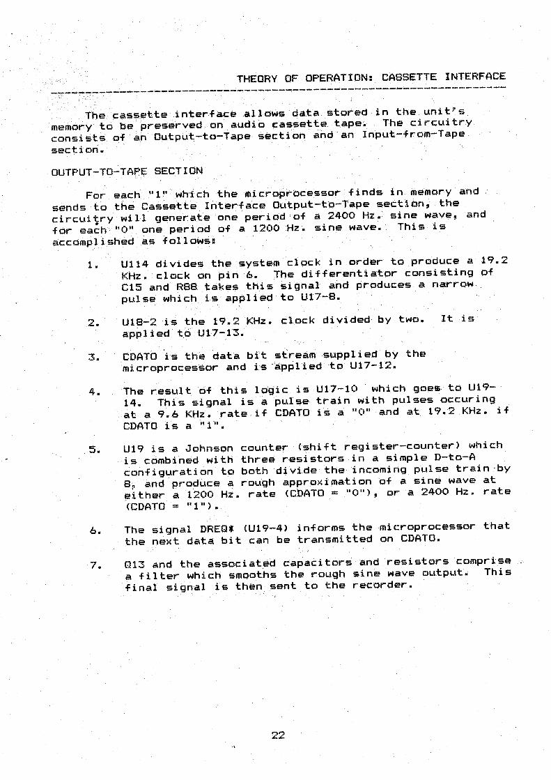
THEORY OF OPERATtON: CASSETTE INTERFACE
. . .-. __ The c.~s~ette }nterf a.ce al low$ data stored ·in the . unit• s
memory to be preserved ·on audio cassette tape.· The circuitry
consists· Of an ·outpLit-to-Tape- section and .. an lnput-from-Tape .
section.
OUTPUT-TO-TA~E SECTION
For each II l II which the mi croprbcessor -_finds,· in me·mory and
sends to the Cassette Interface· Output-tq-Tape section, the
circuitry wi 1'1 generate one --period •·of a 2400 Hz. sine wave, and
for each "0" one period of a 1200 Hz. sine wave. This is
accomplfshed .as .f=ollows:
1. U1i4 divides the system clock in order to produce a 19.2
KHz. clock on pin 6. The di'fferentia:tor consisting of_
C15 and R88 ta~,es this signat and pr-educ.es a narrow ,
puls- which is applied to U17-8.
2. ·- U18-2. ·is the 19~ 2 KHz~ clock divided by two. It .. is
appl i e·d t6 U17-13.
3. COATO ·1 s the data bit stream supplied by the
microprocessor and is ·'applied to U17-12.
4. The result of this logic is U17-10 which goes to U19-
14. This signal is a pul'se train with-pulses occur-ing
at a 9.6 KHz. rate . if CDATO is a "011 and at 19.2 ,KHz. if
CDATO is a "1 11• .
5. U19 is a Johnson counter (shift register-counter) which
is combined with three resistors in a simple D- to-A
con_f i gurati on to both di vi.de ·the incoming pL!l se train by
8; and produce a rough approx i ma-ti on ·of a sine w.ave at
~ither a 1200 Hz. rate <CDATO = 11 0'')~ or a 2400 Hz. rate
(CDATO = "1").
6. The signal DREQ* (U19-4> informs the mi~roprocessor that
the next data bit can be transmitted on CDATO.
7. Q13 and the associated c:·apacitors . andresistors comprise
a filter which smooths the rough sine ·wave output. This
final signal is then sent to the recorder.
22

The general format for data recorded on tape isl
. - LEADER (6 seconds at 1200 .,Hz.>
· - .· then repeated 128 · times: , · - SYNCHRONIZATION NlBBLE (0101) -- DATA (16 Bytes) - CHECKSUM (nibble) - . 2 -BYTES OF ·ZEROS
- TRAILER (1200. Hz. Tenet
23
. .
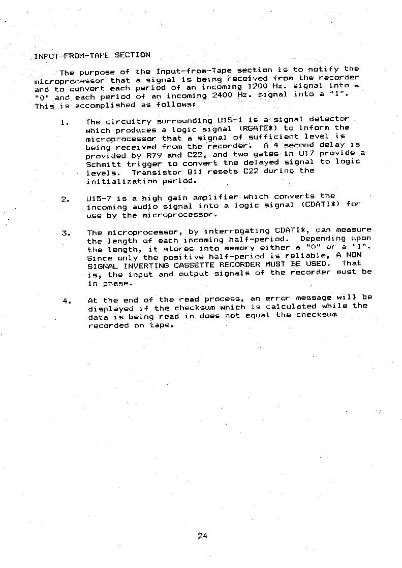
INPUT-FROM-TAPE SECTION
' The purpose _of the Input-from-Tape section is to notify the
microprocessor that a signal is being ' received from the recorder
and to convert each period of an incoming 1200 Hz. signal into a 11 0 11 and each period of an incoming 2400 tfz. -~1gnal into a "1".
This is accomplished as follows:: · · ·
1. The circuitry surrounding _U:15-1 is a signal detector
which produces a 1 ogi c signal <RGA.TE* > to inform the
microprocessor that a signal of sufficient level is
being received -from th·e rec~rder ~ A 4 ·second delay is
provided by R79 and C22, and two gates in U17 provide a
Schmitt trigger to convert the delayed signal to logic
levels. Transistor CH1 resets C22 dLJring the
initialization period.
2. U15-7 is a high gain amplifier which converts the
incoming audio signal into a logic signal (CDATI*> for
use by the microprocessor.
3. The microprocessor, by interrogating CDATI*, can measure
the length of each incoming half-period. Depending upon
the length, it stores into memory either a 11 0 11 or a "1".
Since only the positive half-period is reliable, A NON
SIGNAL INVERTING CASSETTE RECORDER MUST BE USED. That
is, the input and output signals of the recorder must be
in phase.
4. At the end of the read process, an error message will be
displayed if the checksum which is calculated while the
data is being read in doe• not equal the checksum
recorded on tape.
24
COMPUTER INTERFACE DESCRIPTION ' . . .
. ~----------------------------------------------------------------
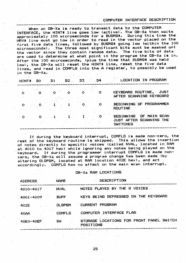
. When an oe...:.·xa is ready to . ttaf<l~fu .. i :t data to the COMPUTER
lNTERFACE, the HINT* line gpes lc:n,/ <~stive> '. The· OB-Xa then waits approximately 190 . microseconds for a ' BUSRCl*· Dur:i ng· this ti.me the . HRV* line must ~o low in order t~ read :in th• vector ~laced on the first five data lin·~s, followe,d '' by BUSRQ* going low (within the 100
microseconds). ·.The three most ~igni.f icant 'b'i ts must ·be masked off the vector si nee the:iy contain ra.ndom dat~.· ··The five bi ts of data are used to determine . at what point in t _he program 'the OB-Xa is in.
After the 100 microseconds, <plus the time .that BUSRQ* was held
· low>, the OB-Xi\ wil,l reset the HINT* line, reset the five data lines, and read in COMFLG into tha A re~ister, t6 p6~sibly be used in the OB-:Xa. · · ·
HINT* DO D1 D2 D3 D4 LOCATlON IN PROGRAM
---------------------------------------------------------------~ . ' .
0 0 0 0 0 0 KEYBOARD ROUTINE, JUST AFTER SCANNING · KEYBOARD
0 0 1 1 0 0 BEGINNING OF PROGRAMMER ROUTINE
0 0 .1 1 1 0 ·BEGINNING OF MAIN SCAN JUST AFTER SCANNING THE
' '
SWITCHES
------ ~------------------------ ~ · -----~ -~ -- ---- -----------If during the keyboard ;interrupt, COMFLG is made non-zero, the
rest of the keyboard routin~ i~ skipped~ This allows the insertion of notes directly to specif1c voices· <cailed NVAL, located in RAM at 4010 to 4017 hex) while ignoring any notes being played on the keyboard. · If during . the programmer interrLlpt COMFLG is made non-
. zero, the . OB-Xa will assume a program change lias been made (by
altering OLDPGM, located at RAM location 4~1t hex), and act , ac:cording~y. COMFLG has no affect on t _he main scan interrupt.
OB-Xa RAM LOCATIONS
ADDRESS. NAME DESCR1PTION
-------------- .------------------.-------------------------------4010-4017 NVAL
4001-4009 BUFF
402E OLDPGM .
40AA COMFLG
40E0-40E;F SW
NOTES PLAYED BY THE 8 VOICES
KEYS BEING DEPRESSED ON THE KEYBOARD
CURRENT PROGRAM
COMPUTER INTERFACE FLAB '
·,
STORAGE LOCATIONS FOR FRONT PANEL SWITCH POSITIONS
----- ·------- ·---- ·------- -- ·---- ·· "·------ ·--------------------. .,.
25
NVAL:
BUFF:
OLDPGM:
COMFL.G:
SW:
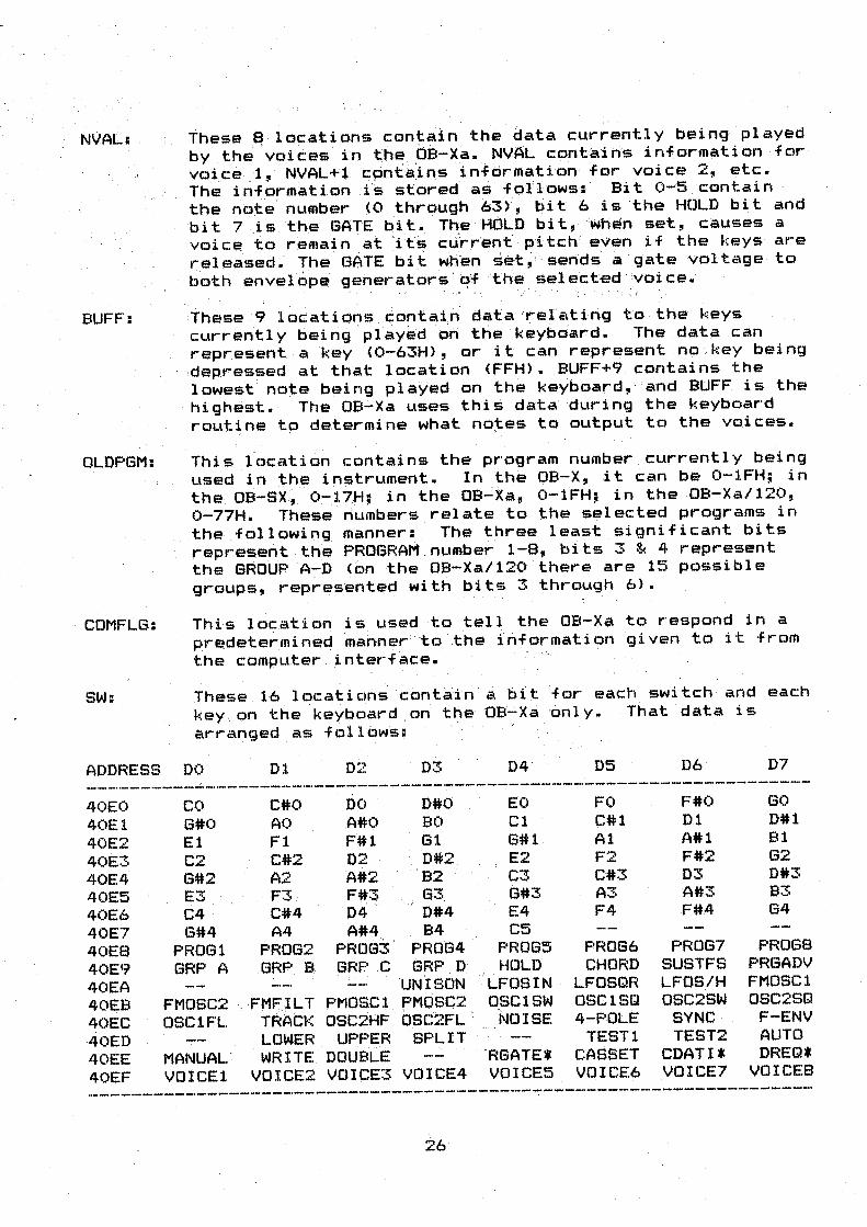
These 8 locations contain th~ ~ata currently being played
by the 'voicesin t:h~ OB-Xa. NVAL contairis information for voice .1, NVAL+l c:;s:mta:ins information for voice 2, etc. The information i~· stored as fbtlows: Bit o-s ~ontain
the no_te· m.,mber ~O through 63), bit 6 is the HOLD bit and
bit 7 .il:> the GATE bit • . The' HOLD bit, when set, causes a
voi c~ to r .emai n at 'its c:drrent· p'itc:h even if the keys are
r:eleased. The GATE bit when ·set~·· sends a "g·ate voltage to
both ·envelop~ generators . qf t'he selected Voice.
These 9 1 ocati ems c:ontai n data 'rel'ating to the keys currently being .pl.ay~d 'on trie keyboard. The data can
represent a key (0-63H>, or it can represent no key being
· ,depressed at that location <FFH>. BUFF+9 contains the
lowest note being pl aYed on the keyboard, ·' and BUFF is the
highest. The oa~xa uses thi• data during the keyboard
routi .ne to de.termi ne what notes to Ol.ltput to the voices.
This location contains the program number currently being
used iR the in~trument. In the OB-X, it can be 0-tFH; in
the OB-SX~. 0-17:H; in t:.he oa...:xa, 0-1FH; in the OB-Xa/120,
0-77H. These riumbers relate to the selected programs in
the .following ,nanner: The three least significant bits
represent the PROGRAMnumber 1-8, bits . 3 & 4 represent
the GRou·p A-,D (on the OB-Xa/120 there are 15 possible
groups, represented with bits 3 through 6).
This location .is used to tell the OB-Xa to respond in a
pre.determineq 'manner' to ' the information given to it from
the computer . interi•ce.
These 16 loc:ation~ contain a bit for each switch and each
key . on the keyboard .on the OB~ Xa only. That data is
arranged as follows:
ADDRESS DO Dl 02 D ..... .... 04· D5 D6 D7
-------------------------------------------------------------------40EO co C#O DO D#O EO FO F#O GO
40E1 G#O AO .A#O BO Cl C#l D1 D#l
40E2 El Fl F#l G1 G#l Al A#l Bl
40E3 C2 C#2 D2 0#2 E2 F2 F#2 62
40E4 G#2 A2 A#2 B2 C3 C#3 D3 D#3
40E5 E3 F3 Ff3 63. 6#3 A"T A#3 B3 .... 40E6 C4 C#4 D4 ,;; 0#4 E4 F4 F#4 64
40E7 G#4 A4 A#4 . B4 C5 40E8 PROG1 PROG2 PROG3 PROG4 ·PROGS PROG6 PROG7 PROGS
40E9 GRP A GRP . B GRP .C GRP D_ HOLD CHORD SUS TFS PRGADV
40EA UNISON LFOS IN · LFOSQR LFOS/H FMOSC1
40EB FMOSC2 , FMF.-IL T PMOSCl PMOSC2 OSClSW OSC1SQ OSC2SW OSC2SQ
TRACK OSC2HF ' ; ~
40EC OSC1FL OSC2FL NOISE 4...:..poLE SYNC F-ENV
-40ED LOWER UPPER ·sPLIT TESTl TEST2 AUTO . . - .
40EE MANUAL . WR I TE DOUBLE RGATE* CASSET CDATI* DREQ*
40EF VOICE1 VOICE2 VOICE3 VOICE4 . VOICE5 VOICE6 VOICE7 VOICES
26

Here is: an description of how communication occurs between an 0£:1-Xa and ·a DSX when connected together - through the computer interface.
,.
The DSX, while in play, keeps track of the current "time of day 11 with its real time clock and decides whether or not it is time to play a note. When it is -time to play a note, the DSX stores that note · into a particµlar place in its memory. · When it is time to stop p 1 ayi ng that. note, it ·. takes the note out · of that pl ace in memory. In the mean time, if ·"·the OB-Xa has reached: one of its three ro~tines in which it calls the Computer Interface, it will place a vector ont6 the first 5 data lines and set· the HINT* line 1 ow. This. signal causes a nonT"m·askabl e i nterrL1pt to occur in the ZBC> of th·e DSX, forcing it to .. ,stop what it is doing and immediately execute a specific part of its: progr~m. This program will read in the vector and then set BUSRQ* low. The 280 in the OB-Xa will send a BUSAK* signal and then stop -everything until the BUSRQ* line returns to its normally high state. The DSX will then determine, using the vector, whether or not any communication is necessary between the DSX and the OB-Xa. If the vector indicated that the OB-Xa was in its keypoard routine and the D.S~' had, a note to play, the DSX would then output the note into th~ appropriate memory locatio~ of ~he OB-Xa and make the memory loc-t~bn COMFLG non-zero. After thjs the DSX would return BUSRQ*- to a~igh state, allowing the OB-Xa to . resume its program. · , The OB-Xa would then output the note to the proper voice.
27

. · •,,(·,. • . OB:'.""Xa CONNECTOR DIAGRAMS ,·. ' . . ,, ' . (·.~0.:.0:.· - . ' -·· _·- -- -~-~- -·- ·. - ;, • -- . . --· -:~ -------· .. ----.-- .. -- ' ; - - ·- .. . ~~z:· '0 :~--- .. ---.. - ------ · -
c ~ t~LE tt3 -- Power Supply to Lower Mother Board
CABLE #4
POWER. SUPPL. V. ,, MOTHER BOARD ; . '
. . · ·. ,.,,... ' - . · .... :- , - __ . .. . ., . . . ~- . ,. · ... , ···. '
PHl PH2 PH3 PH4 PH5 PH6-PH7 PH8 ·; PH9 PH10 -•
..
., , ·~
-15V
+ _15V , +15V :
GND l;iNO .. ·· :GND .GND :'.'."5V , , ;•: .. -5V
' -- .
.MLD1 MLD2 MLD3 MLD4. MLD5 MLD6
-ML:D7 MLD8
·MLD9 .MLD10 ·
Power S\.tppl y , to Upper · Mother B.oard :
· F'OWEf3 SUPPLY .Mother Boar d ' · • ' . - ·, .. -- -- ~ -- ..... - . . . . : - :· .,,:- .. -.: -_:· . .
.PG1 PG2 PG3 PG4 PG5 PG6 PG7 PG8 PG9 PGlO
-. . --15V KEY
+'15V +15V
GND GND GND GND ,;-5V -5V
MUI>l MUD2 MUD3 MUD4 MUD5 MUD6 MUD7 MUDS MUD9
· MUD10
CABLE #6 --- Mother Board to Re'a.r Panel
MOTHER BOARD ------- --------------------- ----------------
Fl F2 F3 F4
AUDIO OUT LEFT GND GND AUDIO OUT RIGHT
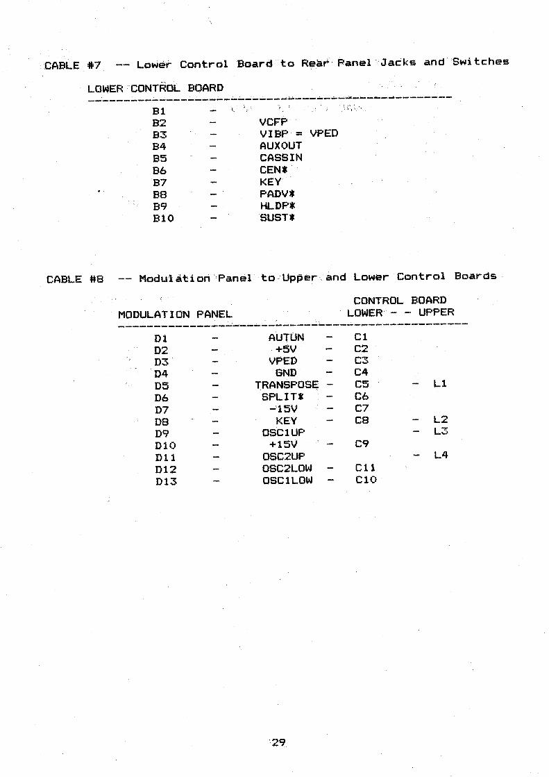
· .. CABLE #7 -- - Lower Control Board to Rear · P.anel ' Jacks and Switches
LOWER 'cONTROL BOARD
----------~--~----~-~~~~-~--------·----------------
CABLE #8
Bl l. · 'l . ' 'i ·: \ \ .. ·· •· . '
82 VCFP· 83 VIBP = .VPEO B4 AUX OUT 85 CASSIN B6 CEN* · B7 KEY- ...
BB PAov• . . ..... , B9 HLDF'*
810 SUST*
Modu'l ati on "Panel to -Upper . and Lower Control Bo.ards ·
MODULATION PANEL CONTROL BOARD
· LOWER- - - UPPER ' ; . ... .. . ----~-----------:---.-----------------~----------------
Dl A.UTON Cl 02 -+5V C2 03 VPED C"':!' ... 04 GND C4 05 TRANSPOSE; - C5 Ll 06 SPLIT* C6 07 - '15V C7 08 KEY CB L2 D9 OSClUP L3 010 +15V C9 Dl 1 OSC2UP L4 012 OSC2LOW C11 013 OSClLOW ClO
' 29

Power S~pply to Upper Control , ~oard .
UPPER CONTROL BOARD -,. ,_ :_ POWER -SµPP.LY _ • . --. wi- . ------ . ---------- , ------. . . ---- . '--. . . -.: .•.. . ... : . . --------
A1 A2 A3 A4 A5 A6 A7 AB A9 A10
5VAC <FOR PUP CIRCUIT> +5V +5V KEY -,.
+15V i
GND GND
.:..15.v -15V
F1 - F2
F3 F4 ,F5 F6 F7 FS
, F9 , FH>
CABLE #10 -- Power Supply to -Lower Contr-ol Board _
LOWER CONTROL BOARD ,, POWER SUPPLY - '
. . . -,~ ..... ~ .
Kl - 5VAC <FOR PUP CIRCUIT> - - El •<2 +5V · E2 K3 +5V E3 1<4 KEY E4 1<5 +15V E5 1<6 +15V -E6 K7 GND E7 KS GNO ES K9 -l5V - E9 l(10 -15V: ElO
30

CABLE #15 -- .· Lower Control · Board to · Rot Board
LOWER CONTROL BOARD POT BOARD · (connector not marked)
--~-------------~----~--------------------~---------~--El E2 E3 E4
.ES E6 E7 EB E9 ElO Ell E12 E13 E14 E15 E16 E17 E18 E19 E20 E21 E22 E23 E24 E25 E26 · E27 E28. E29 E30 E31 E32 E33 E34
31
LR07 LR06 LROS
. LR04 LR03 LR02 LROl LROO
GND ANLGIN
GND VOL POT
MTUN
SWENO* -1sv:. +15V;
SWENE* CEN* ·
+Sy SWD4*
. SWD7* SWD2* SWDl* SWDS* SWDO* SWD4* SWD3*
AR5 AR4 AR3 AR2 AR1 ARO

CABLE #16 -- Upper Contr;ol Board ·to -_.Lowero ,Cgntrql_., ~oard '. ·
· UPPER' CONTROL BOARD . : : ·-· LOWE_R .,~ONT.ROL BOARb .' ' ~ . . .. - ' . . . . . ----------.~- - ------------------------------------ --------
D1 A4 Dl D2 A5 02 03 A6. D3 04 A1 D4 D5 A2 D5 06 A3 D6 D7 AOA D7 DB A9 08 D9 AB ' .~ D9 010 A7 D10 Dll D7 D11 012 D6 D12 013 D5 D13 D14 D4 D14 015 D3 ''r . D15 D16 02 016 017 01 017 D18 DO 018 019 IOR* 019 D20 Af'ILGOUT 020 D21 MTUNE 021 D22 OSCMUX- D22 D23 URSO* = · LR50* D23 D24 NOISE 024 D25 SPLIT* D25 D26 IOW* - D26 D27 CEN* 027 D28 LLFO D28 D29 ·ATRST* D29 D30 030 D31 LLFO 031 D32 VCFP D32 D33 CASCLK 033
CABLE #20 -- Modulation Panel Internal Cable
MOD PANEL CONNECTOR A MOD PANEL CONNECTOR C
Al UP TRANSPOSE Cl A2 ON TRANSPOSE C2 A3 NARROW C3 A4 ' 2 ONLY. C4 A5 KEY C5 A6 MOD 1 ' C6 A7 MOD 2 C7 AB GNO ca A9 .,... +5V . C9 AlO AU TUN ClO.
32

CABLE #21 -- Computei::- Interface ·(Upper ' Control Board to Rear' Panel>
CONTROL BOARD
X1 X2 X3 X4 X5 X6 X7 XB X9 X10 X11
REAR PANEL INTERFACE CONNECTOR . ~~----------------------------·. HA 11 .. - 37
. . HA 10 36 HA 9 35 · HA 8 34 HA 7 33 HA 5 32 HA 3 31 HA 1 30 HD 0 29 HD 1 28 HD 2 27 HD 3 26 ARV* 25
BUSRQ* 24 E&USAKA* 23
HINT* . 22 HWR* 21 HMRQl ·20
HRD* 1 GROUND 2 GROUND 3 GROUND 4 GROUND 5 GROUND 6 osc MUX 7
HD 4 8 HD 5 9
· X12 X13 X14 X15 X16 X17 X18 X19 X20 X21 X22 X23 X24 X25 X2'6 X27 X28 X29 X30 X31 X32 X33
· HD 6 10
X34 X35 X36 X37 X38 X39 X40
HD HA HA HA HA HA HA HA HA
7 11 0 12 2 13 4· 14 6 15 15 16 14 17 13 18 12 19
This diagram shows the locationi of PIN #1 on the 37 pin Rear Panel Interface Connector:
PIN37
33
••••••••••••••••• ••••••••••••••••
08-XA FEMALE
CONNECTOR.
PIN1
PIN20

Upper :nether ·Board.:.to Lower. Mother. .. Bow.ct, \ . ... , .. : ··, .. _._, -.,
Ef . . E2 ·· E3 E4 E5 E6
:-.--
' t"'t - •. -
Pot Boa.rd Intert:onnec:t List
:LEFT AUD 10 . • R3>6HT .•. AUD lO
BALANCE VOLUME·•
KEY ... , . osc· MtJX
·E1:· . e:2 E3 E4 E:5 j i6 , ..
NOTE: These connectdrs are not labe1ed. The$e connectors are described from top to bottom with. the unit opened up.
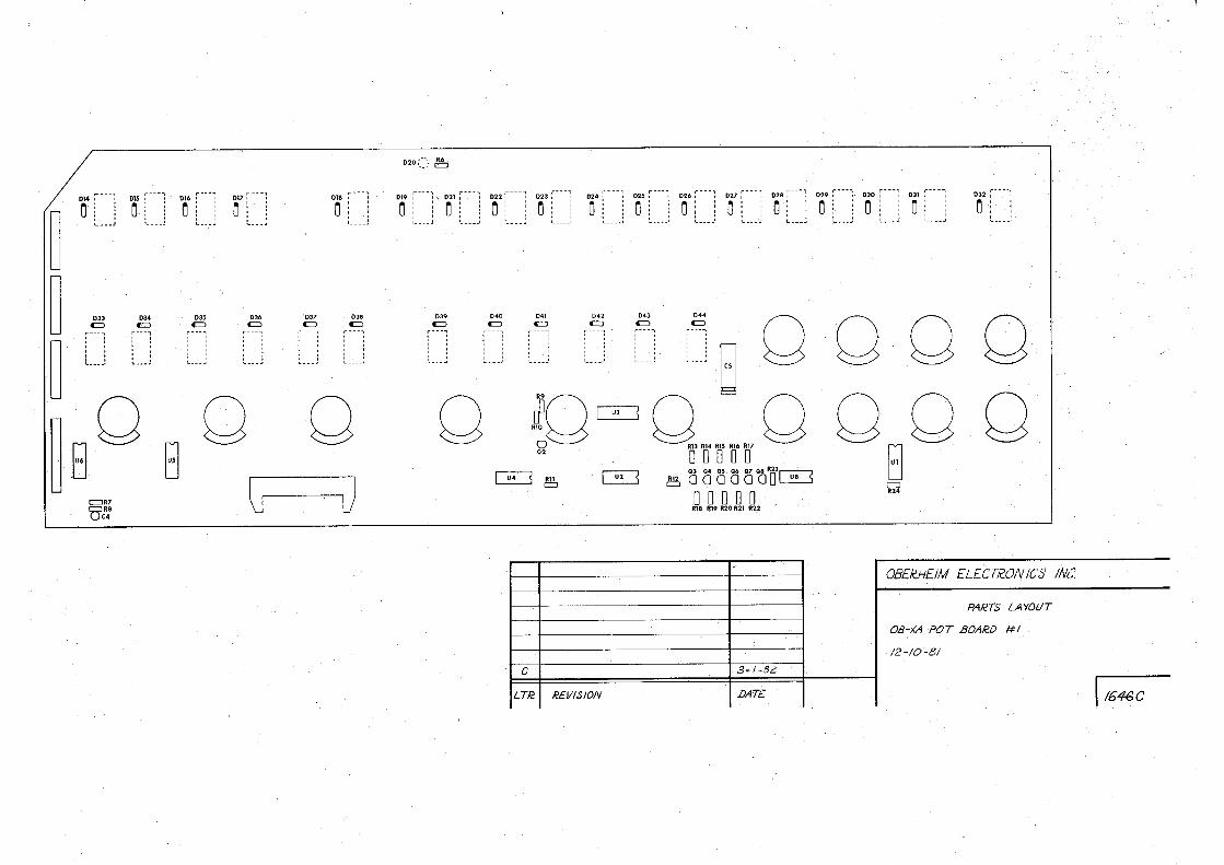
POT BOA~D. #1
At ' , A2 A3 A4 A5 A6' A7 AS
Bl B2 B3 B4 B5 B6 B7 B8
Cl · . C2 C3 · C4 : cs C6 C7 : ca .
SWEN9* ,. (NC>
LED C6 LED R.4 LE:D .R3, LED R2. LED Rl LED RO
SWD7.*. SWD6* SWD5* SWD4* SWD~* · ~WD2* SWD1* SWD0*>·
SWENB* LED ·Ct SWENA* · LED CC> SWEblD*·· .
MI UN VOLF?OT
BND,
D1 +5. 6V. D2 VC02 DETUNE 03 ,PWM AMT 04 FM AMT D5 LFO FREQ
. .- fi6 :· .. . . oa • • .' • • • PORT 6\MT . .. ·: ;q:z \~:~'c/ · ... :···,~"..-f ... 1·~; :) · :D~. . -· ·.,...15,
D9 SWENF* D10 BAL
34
POT BOARD #2 ---- --- -.· ,· - · --
A1 A2 •·· A3 A4 A5 A6. A7 ·-. AB
Bl B2 B3 B4 B5 B6 B7 BS
Cl C2 C3 04 < Ca C~:. C7 ca
01 D2
· .03 04 D5 D6 D7 D8 09 D10
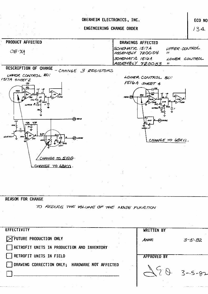
OBERHEIM ELECTRONICS. INC.
ENGINEERING CHANGE ORDER
PRODUCT'·AFFECJED DRAWINGS AFFECTED
ECO NO
J 34.
C>B-?(A SCHe/LlftTI<!.- ·IS17 A t,1pPeR-()()N71<()L.
, A$!:N/3L'I 720DS4 " · 5CHeNt4r1a. lol~A
~ eMJ:Jt.Y : ~owe/t!. coAJneoL
" DESCRIPTION OF OfANGE _ CHt4NGE 3 ·REG1ST0RS
u~ CONrl'<O'- Bl).' 1s17~ s1-1eerz
REASON FOR CHANGE
EFFECTIVITY
~FUTURE PRODUCTION ONLY
D RETROFIT UNITS IN P_RODUCTION AND INVENTORY
D RETROFIT UNITS IN FIELD
D DRAWING CORRECTION ONLY; HARDWARE NOT AFFECTED
.J..OWE"li:. CON'T7<0L 80/
/5"/~,i .$1-JEeT 4-
WRITTEN BY
PPROVED BY
3-s-82
3--S-9'l-
. ------ - - --- - --
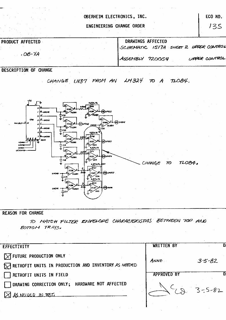
OBERHEIM ELECTRONICS, INC. ECO. NO.
ENGINEERING CHANGE ORDER l3S
PRODUCT AFFECTED DRAWINGS. AFFECTED SCHeMftTIC IS17A SHEl'.!7: 2 J.JPf:elr< ~OJ..
DESCRIPTION OF OIANGE
CHltNf:,e 70 TL-084 •
REASOO FOR CHANGE
10 HATCH Flt.:rz:R r:NYl!JI..OPE CH1tRA/!.,71:fR/S77C!S 8£TWE£N 70P ,<J/l¥J
/3oTffJH T~ltY6,
EFFECTIVITY
(21' FUTURE PRODUCTION ONLY
Da RETROFIT UNITS IN PRODUCTION AND INVENTORY AS Nff'DE:D
~ RETROFIT UNITS IN FIELD
(=1 DRAWING CORRECTION ONLY; HARDWARE NOT AFFECTED
. ~ /6 NEfDE;D JN 1J$Ti·
WRITTEN BY
1/NNf:- 3-S-82.
PPROVED BY o.

OOERHEIM ELECTRONlCS , . INC. ECO NO.
ENGINEERING .CHANGE ,ORDER
PRODUCT AFFECTED
I
DRAWINGS AFFECTED SCHeH /!TIC /~/fll A sHeET 4 (R'S,&J/e 'R4NEL) X.Hl3MftTIC 1519.A H01rle~ .Bl),
AssEN&-Y 720057 f 7zoosz~o (towEII!!.) A.::!:6EN5t-Y 72.(X)~/ i 72..00tJI-O ( uPA!:r~) . .. 1'-181- 750tZ9-/ Cit 'J.f:#7
DESCRIPTION OF OiJ\NGE /, <!.,HrtNb~ A 7lJT;t:tL- OF- + ~I$~ FER 08-ZrJ UN IT
Pl<OU 1:13K 70 I ~CJ K,,.
· CHIINl!.I: .ro · IZOK ON TWC, HaTHe~ 80~/?()S.
9
- s 7
REASOO FOR CHANGE
TO /N~f?.!=,tJSl: G/11/11 (Y= ourPVr.
EFFECTIYITY
l2f FUTURE PRODUCTION ONLY _.
[2:JRETROFIT . UNITS IN PRODUCTION AND INVENTORY
G2rRETROFIT UNITS IN FIELD
D DRAWING CORRECTION ONLY; HARDWARE NOT AFFECTED
D~~~--~~~~-
Z, CHAN&.c llES1slQlii? ON CAGseT7fff.
HON /"TOR 5WI TCH ( Rl!~te Pl+N~l..)-rP
~ K.n • rH,s m1SES Cl'ISSl:77q
HCJIV/70~. ~LJHe1 l(ee-PIAIG- /i!A:'TIO
OI= 7Hc VdLUHeS OF $YM'HES 1z.EJ2. .
our-PtJT "WO C.+6.s~77E HOAJ 11'01'2..
WRITTEN BY
3·$·82.
BY
DATE
DATE

OBERHEIM ELECTRONICS, INC.
ENGINEERING CHANGE ORDER
>RODUCT AFFECTED DRAWINGS AFFECTED
06-XA
JESCRIPTION OF OIANGE
,CHAl\.lf.E .€PROM LA6t..eD XA-6¢ (PAer l,l(), 31~1-<=<t>)
€PROH LA6Lt::t> M-6A(JS (PAT(T" t.JO, 31~¢,(/)I - GA(/;)
£XPL1tNA-r10N ·~
ECO NO.
/40 ,
/; ENTciR. HltNUA'L JJ/005,
z. WH/1.,e ;N NAAJ,l)ltJ. NDD~, PEteFCJRH AN11
E/)1T :'{£.tAM'Fi:e:: T?/tl$~ · THE Fie6G OF VC.02
UNTIi- Ir I,$ 001)81..t:/) ,)
..3, PLJ:SH W/f 1,,-e: 8'1i7dN
'1--· ~H PR(J$,RA-M tvl)N8~ You 'YV,'lrN r ~ve fftra.rt IN
S, J..el ~o at= PRo~~l'tH N)JMBe-te. 8Vi1r:JN ~§FOli!..t::: , You b, t.eT ~D OF W/i?IT'E BVTTON,
IF Y6u usTEN .Now, vco z. w,1-1- gc_ rov-a1..e,t;/ A'6tlf-lN. rr'.s t'IS 11= T+I£ SIMI'=
eo,r WEJef:3 PERR:)/!?NffD "tWICe' TH!: P.et:,SR~ WAS :;;ql"ED ~Y..,f*3~. 'P.llSHJ
Tfl'(~ Pk?OGl<AM Bonr>AJ AfA-J/\1 Wll-l, l!ESTO/€(: ~u.-e WJ-'fr!H.
iH/5 cl(eote.. I.S COJeR.fJCTEfO IN fl,4 -<:;;~ -
~EASOO FOR CHANGE
" # ' teJ ct-tM!NltTe !:Dl,-'OCJU8LI/\Jf-. ltRf?OI< CQNT40J/:-O IA). JA ·<!.¢.
{~eE: £XPt..ANATt()N A&J'l't:)
::FFECTIVITY
~ FUTURE PRODUCTION ONLY
OJ RETROFIT UNITS IN PRODUCTION AND INVENTORY
D RETROFIT UNITS IN FIELD
D OP.AWING CORRECTION ONLY; HARDWARE NOT AFFECTED
D~~~~~~~~-
WRITTEN BY
REF. SQOZ.
DA.
3-l/--82..
DA'
OBERHEIM ELECTROOICS, INC.
ENGINEERING CHANGE ORDER .
PRODUCT AFFECTED DRAWINGS AFFECTED
os- x'l. 5o-'1en,,~ - /SIS
DESCRIPTION OF OiANGE
qi),~, 7 Z, 3 r~f l,f {-,.~v i + /tiJ oJ. ~ +5
/,, I''"' I 2. "! ~ -5 ,1N1 y,1,.J !''"" 4 lo ~ t.'I;.., ("1".
REASOO FOR CHANGE
+ 3300,,, 2SV
/Ir Ult
4-47Jc, 1%
,,9//" Iv ~,., c,/Je rlfl/.~ ·~ ~
EFFECTIVITY
~ FUTURE PRODUCTION ONLY
0 RETROFIT UNITS IN PROOUCTIOO ANO INVENTORY
0 RETROFIT UNITS IN FIELD
D DRAWING CORRECTION ONLY; HARDWARE- NOT AFFECTED
D--~--~~~~~-
r------, - - j)- /fl.
Ill
ECO NO.
/43
DA",
DAl
FRONT PANEL REAR PANEL
POT BOARD ,JACK AND SWITCH ASS>;
r 1518- -r - - - -I
VOICE' I
- 5 -
, .,
-LJ
-- - - - -- I /520 -
- ~ ... --..___
POWER SUPPLY UPPER CONTROL BOARD
-- VOICE
I
- - - - -I /5/5 I .- -:- - - ~
: 15/7 -- ~ ... LOWER CONTROL BOARD - - - - -
I /5/6. '
a - - -- -: 1520
--.
MODULATION
PANEL
KEYBOARD
r--:- - -, /521
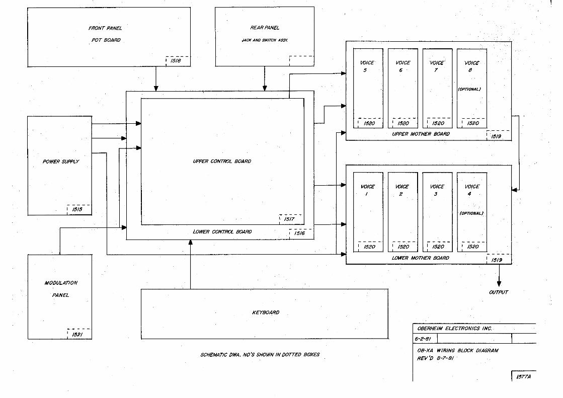
SCHEMATIC DWA. NO'S SHOWN IN DOTTED BOXES
.. ..
. •
·. .·. , ·,.· ... ,_,-_ _
'VOICE 'VOICE' 'VOICE'
6 7 8
.·· .·
(OPTIONAL)
- - - - - ,.- - - - - - - -.- -I /520 I /520 I /520
---- - -UPPER MOTHER BOARD : / 519
VOICE VOICE VOICE
2 3 4
(OP710NAL)
..... - - - - ! 1520 -- -- - -
: 1520 : /520
- - - - -LOWER MOTHER BOARD ! 1519
,, OUTPUT
I OBERHE( ELECTRONICS INC. ..
6-2-81
OB-XA WIRING BLOCK DIAGRAM
REV 'o 8-7- 8/
......
*
I
r 1577A
G G '!, POT BOARO No.2 G u
6 ~~IPSW/TCH G u H G a
' - - - - - - - - - - - -
~
-I '
0 ~A
~
'·--·····o
~K
i==1x c::::J
t DL ./ r·1
' '
aaaa~[ : i A 8 C 0 ·-"E
UPPER CONTROL BOARO r E r•• ••t
P~R G~ij L ... JF
t SUPPLY
~c:::::::,o c c::::::, :
I BENOBOARO No.2
I [~~J I I I 9r·- ••1 I
l 1..---' l I l I I -- - - --------
D r - - - - - - - - ;: .. : .... - I 1 A'···--- l
I 8ENOBOARO No./ I
L-- - - - - - - I
_,
- - -
r--.
Ncp Gl •• , ;
H•-·· ' ) ' ' ' ' ' ' ' ' L .. /
J r- ... ' l : I
' ' ' ' ' ' t..,)
·-
POT BOARO No. /
c::J
- - - - - - - -
c:::Js
MOTHER VOICE I VOICE 2 BOA RO
c:::J C
~o
KEYBOARD
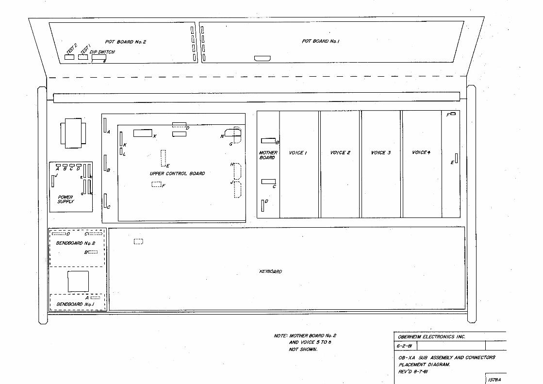
NOT£: MOTHER BOARO No. 2
ANO VOICE 5 TO B
NOT SHOWN.
- -
VOICE 3
I - - - - - ~
~
L
Fr::J
VOICE"I-
ED
'--'
OBERHEIM ELECTRONICS INC.
6-2-81
08-XA SUB ASSEMBLY ANO CONNECTORS
PLACEMENT DIAGRAM.
REV'O 8-7~
j t578A
,rs +rs OSGI
+!S
T~ .;.1S 100,<:i IM£G,R6 /NIT~ l"REQ ©
11.12 IMEG
'"' -,,
46,21<.
'"
.&
/Olr,1%
U/
VC~IF(~
FTA
IM,.Es" i lO/f, 72 C£M ~-~
3340 © Tl/AC!< :~n. '-:- . s
t·0/1C/
12.
T 7-Slr
'" IOJc,74 !NIT .01, cz I PW
J
IJ_
,,
lo
4.7M,~U4 1%
.f 3301< I/S2
/21 40/6
KEYC'I
+/5" osc 2.
1ffS. ,1,-.M.-R.'4, T7 +-vv~
0 /N/7 FkEq
7 IOOlr
.as-•
\<,>ZF~
IM,1% 1/30
-s
7S IOI(
IOI<, /'ii.
© I -,,~ p V/IPC°., IS TURN
46-21!-l,II,, /)'.
z
~-"' /Olf.1 76 FT8 (Al~~H/7111/CI<
!Mk ~ t~;.79
M,0
ij 3
Pf
~+IS ns
1s,,l, C3G.
47<>Jt fi!.28
~
s
7.s1r k.2 S
J 221< /0Jf,T8
~'t{I
~
+{S
~
U 2.
CGM 3340
IZ.
1-(S
I~
~
.1c
t.IM,ll<
7-S~ R2/
fi!.29 ~~ 14 l,8ZJ<,1'11,
/0
.1
VC(#2L
+ -s ©-r-s
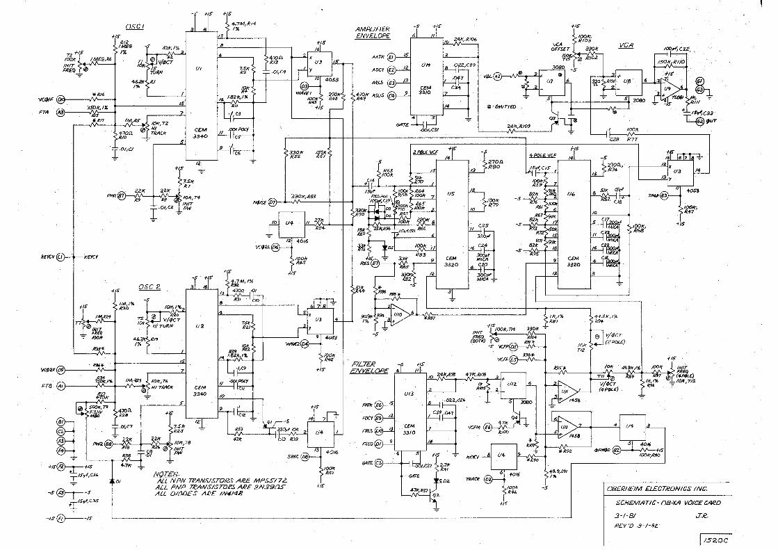
DI ,ALL /VPN Tli'ANS/.STORS AR£ MPSS/72. ALL PNP n?ANSISTORS AR£ 2N39DS ALL DlfUJ£S ARE IN4!4B
i 1s,,,c3S
c:,._ __ ,s -IS~
IODk ll.4S
f/S
+is
ISO,: //,SI
+is
f!S
HS
AMPLIFIER -s +!S
ENVELOP£
-·~ t AOCY .-.... ' ~
un
A~LS '-./ CE/VI
~Ir ASUS 3310
GATE
~ +{S
-:S
FILTER -r ;;s ENVELOP£ 6 ti!
FRl-5
GAT£
us ·
CEM
3320
"3
·::02.
· ® • '/wl! TTEO
/NIT
(=)
24~,1t.10,
270!1 RBo
1001< R79
.;is
~
-s~
-s~
12.
f /f,1% Ii.B l
ftS
f-/S
C£M 3320
-.s
VGA
,~ ,
!')--+--,1\/'-ftS !OD~,~
l°'!/'f,C32
®··.· (§}-J_
llr; .,. 1<.111
+..L,s,')c33 L...@11ur
+IS
0B£ RH£IM £L£CTIWNI CS I NC,
SCH£M/ITIC- OB-XA VOICECARD
.3-/-81 J.,€.
R£V 'D 3 - l ·Bz ·
I /520C
BAt.l~
, RS /U ~z
-s_7_
i#SCMUX
*= UPPER 811>/{/i/f) OYVLY
* ~ = L(J)WEP. 8f1Aro t3NLY
'E2) (El
r------1
I I ______ _
REAR ,..N£J..
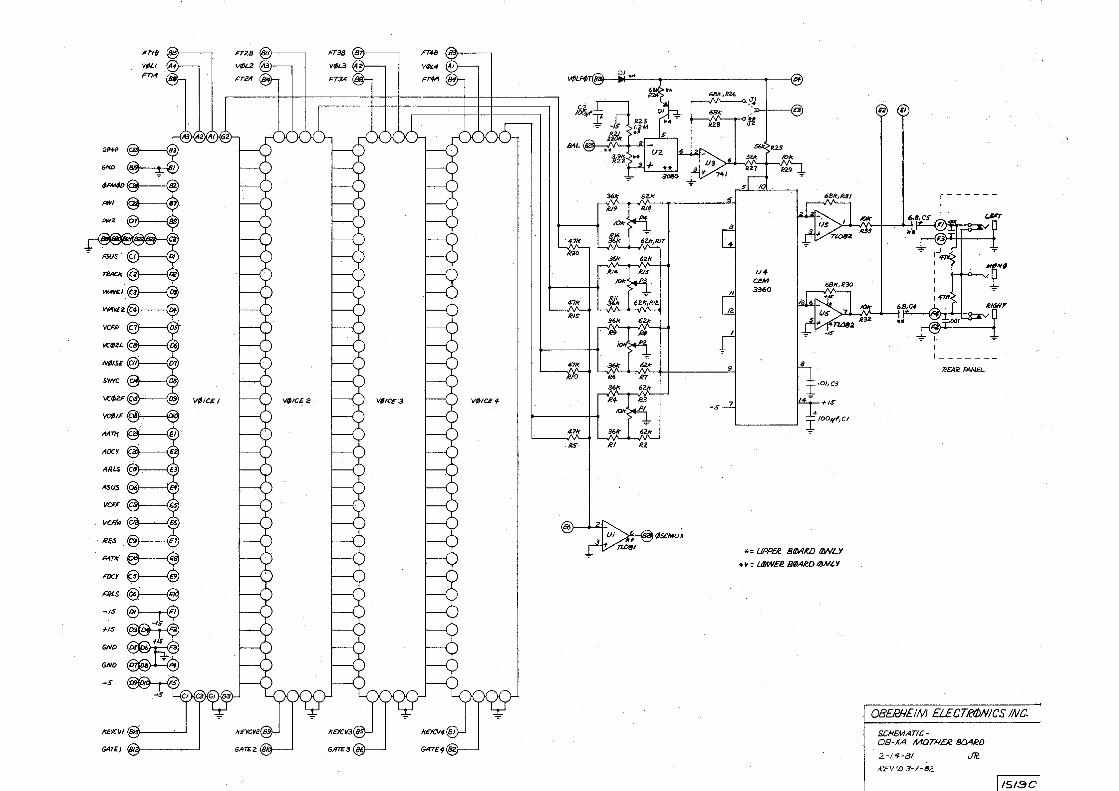
OBERHDM ELECTR(!)NICS INC.
S.CHEMATIC-OB-XA MOTH£/2 804/W
2-lf-8/ JTc
li'EV'L! 3- / -82.
[ !51:3C

CJ«~
+ ~.a.i
ce, 10~,+.
I-$'
AOi""-AO
Y!OI r;-.1111
00
07
.\'I) 91 .l'v\ti
~ ~ +SMEM
-~ AJ..Lj
A11':!l
I_
"I I I DO A2 9 {)() A2
A3 10 DI A3 0/ 02. A4 DZ A+
l)3 Af "= ' ~ ,, ·D4 A6 14 04 A6
A7 I IS Dr A7 ·OS D6 Aa . ' "1 ~ :: ·07 A9 . D7 ••A 19
I ~ .... ~ All . I PR/J&e* ~ W,tO
-c,o, ..e22, 33.Pf' 220
ll.'02
I ~
7~Z.
~;9s~ · 100 1 1~ u,21
2. 2. =. Aa4 AO~
Cl.I< ~49 ' 7404
6116#1
74-~
.f',>
~I Al AZ
~·· Ail
(//08 . M 0./
AS A<5 I oz
0.3 ! '
I -,.~
1-S l-5jMOI ~ _.--J____,
,40
u,w r 11 _ ~I r r ()/ A3 . . I ()/
l>Z A4 4 I OZ
AS ' u,64 . D3 t>s OS A6 ()4. . A6 . • I t>. ,~: DS A? · OS
06 A8 (M , I 07 . A9 /J] A9 D7
... _ /9 A10.!1
I R.Dll:j·
6/16~ I PR0&1f-~ WIMJf
,~)UIIYAYEZ
.A7Cili!O.f
Arcl'clll
l.4/:1,/(/11)
~
"'
·~
%-~ 1r:::-:\..s ~~
7f()C ?f04
~~(MZ80N.<•«rVKm) +s~~~ ~~--
Pl<06J:
~04
t;./-
=- 4¢.// -=- 4-011 4()1/
OBERHEIM ELECTRONICS INC.
SHEET ! OF3
SCHEMATIC OB-'iA UPP£/i? CONTRDL. BOARD 4 -28 ·81 .T/i?
A'£V'L) 3-1 ·82
f 1snc
I/LF¢ CV ----.f\1\--4.-l
~
C27, IS~
lfNJ.G
WJIM8
U/41
IN
USHIIAC
/JFSNM4-----.,
ANLG4,</T
US/IH'1
USHM8
l/SHMC
UESIIMS/f
Li) TRANSPOSE~
+_/7L~~
- . UASUS //ffO
WCAS +- TL08f
C20 I ~
Ul'/0
--.--...il .. ,,<""'4 UNES.' .l.. .. ~ " • C2S
:r · 'IJiUVCFMU.
· vv,cv
lll'CAR
UV"1D
~
CZ
9
UVCM (//WhCV
flS U/:MCV {/- ~
C33 ~ - =r~i1,.3, + . ~Jrlt7 ",CIS
~ C/2 -IS la:, 119 .
M7UN£
+f6 .,,
UJ4S'
..>.J 111
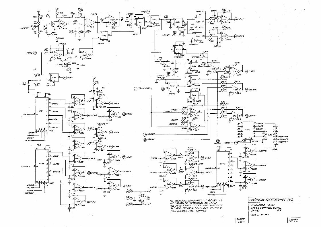
ALL /2£SISTORS DEJ'l6'NAT£D p*' ARE !IXVr, I?. ALL UNMARlr£DCADAC!mRS .ARE . Olif f ALL NPN TR.NISISTCU'S ARE MP.5"5172. AlL PNP ffi'INS"IS TOR.S ARE 2N390S ALL /JIODFS ARE /N4148
QP,Y2.
SHEET 2.C:F.!J
u w:,r,:
UIIC¢1F-
UVC¢2F
UESHM4• l/EG#MS* (/£SHM6*
OBhHEIM ELECTROVIC'S' INC.
~CHEMAT/t' OB·XA {IPPE"R CONTROL BOARD S - ~·81 J.R,
REY'D 3·1-82.
I/Sl7C
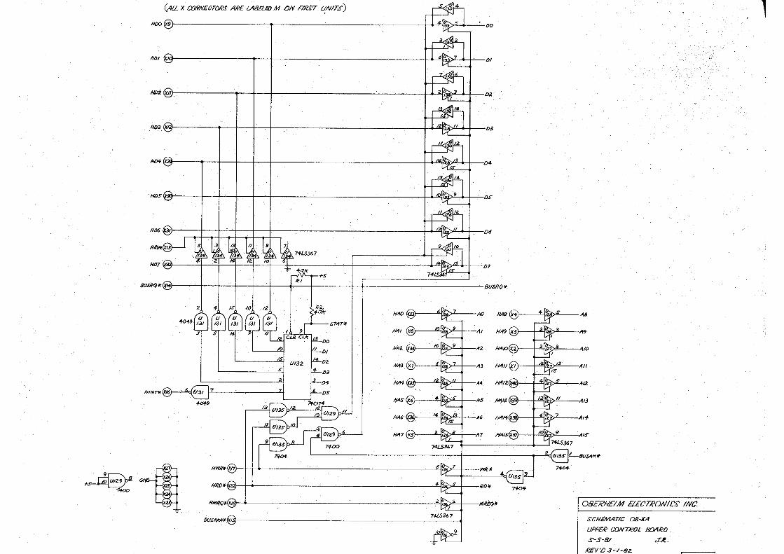
(ALLX CONNUTORS ARE LABELEl)M ON FIRtT ~NITS)
HDO (X9 w:>., j DO
HD/ ~lg T j j j . 6~7 I j /)/
H02 ('XII) , I I I i 2 W.,.:,3 ~ I 02
H03 (x,i) , I I I I I 12~ 11 I I o3
HD+ (X 1i),.., j I D4
Hos ~31} 1 1 · 1 1 1 1 1 &1r,~v ~ , 1 o.s-
J/1)6 W31 1 ~ II I j 06
J/07 ~~ ~, -, 'Tl ·~, ,v, ] I j ,.~,, j . I 07
.-.fV\--+-+s
8U~9•('X BU.fRQ'I-
:/}Jr H40/.w~~
.ST,<fT,lf
/1,1/
#AZ (x34) ' 0 ~'z~.
#A3
JIA4 .IX~v"-+-.
~9 #'1S
HA6'
Jl,lf7
M~ -'/'II)() ·11. HW1c1t.(X17 . 0 ,,.:,,.,-+I--
HRD•(12 ,~';;,.,.s'-'I--
AB
A9
A/0
All
A/2.
·A13
·A l f.
,A/5'
~*S,367
2&8U.s,41rof
7-
OBERHEIM E/.EC'TRON ICS INC.
SCHEMATIC 08-XA
UPPER CON TROL BOARD
S-5-8/ J .f. .
REV 'IJ a-·1-82.
l
/OX ~71(
ts
llWit
714-2.
L/!Olt ·L..e/"1
LR2<! ·L/!31f U/411 LkSI' ·L--e6/f 1.,e7i,
r-------, I /,OLJ)~L I
:~ I _t---.J I
I ~R£4/iMNEL I L ______ _j
az
-----1!..J,~.,,;;;,LSYNC I CZl,.L. [,.:r-- VCJl ·"47::c:
~ "'i•~L~F,'1¢0
Al
~o.'12 A3
7400
~Q.?q--ANLG¢//r
RIOS, 4-.71<:
+S
GATE I oo I @-+s
c~ .,. ;s"'
GATES
GATE6
< C9)-+IS
csa.l+ ,s,,/
• c1)--1S
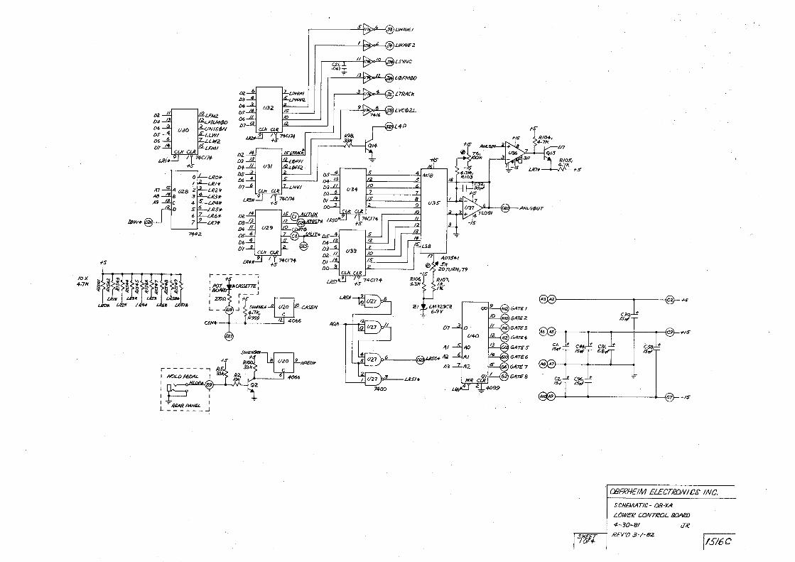
CBERHEIM ELECTRONICS INC.
SHEET /OF.,_
SCHEMATIC · 08-XA
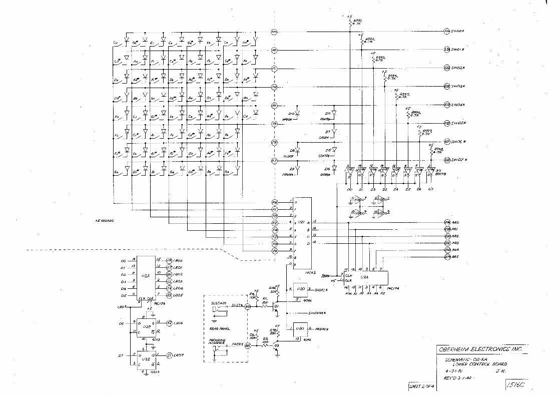
LOWER CONTROL &JARiJ
4-30-81 iT.f?
REV'O .3·/-82 jtS/6C ·
kEYtJOARD
U!O
D6
D7
+s I 12991,
4,7k
(Flo +-"' @swl>O "" R992,
'/-,71<;
+s . R993, 4 ,7/r
f S R994 ,
4 ,71<;
- ------ @swD2.•
'f~,:---·----- [email protected]
R995; 4,7k
f,5" R996, 4,71<;
--@swD4/f
---;s-----@swDSlf
:tl,!7,
--t-- ----@)sw&\5 If
c--+--+-+----+---+---+-t---o--+--+-+---+---+-----4"7 +--+-----l---f---4~ SWD? *
Lli!OO
L.ROI
LR06
- --- -, '
Sl:IS7'AIN
p REAR /WvEL
P"'°6RAM ADVA.VC£ p - - - - -
I
- - - _J
DO Di lJ2 ti3 Lif. OS d6 L>
·- - - ---- @,1Ro
t::::=~-h- - --- - -===®/IR/ I'.! I I 1. - ~: IZ
74C42. N,e/1
SUS,CS/1-
M&'IVII
.--'---------@AR+ I ~ANS
/OI 21 s
U 26
' - 111 .3 , 41 6 AQ1 Al A2 A.3 A1 AS
OBERHEIM ELECTRONICS' INC.
SCHEMATIC - OB-XA LOW£R CONTROL 8[),'JRD
4-21·8/ JR.
REY'D 3 · ! -Bc ·
1.9/EET 2 OF~ l/5!6C

,;r
ANGLq)l.ff IN I ""
;I,B/~--.:i-~""''~
ANGl.¢,VT
llNLG&/r
,s, ~
,[.
I
IJ I LA~7'.-~- I I Ukd. ........._L.LJw15)1(EYCJI/
+POLY ....
,tCl/2
lrE~V3 !<CY'#
lrE'tCYS ,\'CV6
Uk,TV
~ESV ~ Tl.08'1-
IC77
'LVCFM ~-. - L~B<
i/'f-3 L.LFtiCY :;!; -----LLFI/JV + TL084 .
:(~ UMCt'
LP¢/lTCV /.$TOH£
L()Tr
llPC
I I p....F7Vl8
ANGLOOT
6
7 A8C~
II 1£1 Q L. •
7'!h 6,
/6
A,IIGLdluT11N l )lrEYCV8
LSHM8 lSHMC
LESHM31
l.$GC2;
L4lSC!F
LAI/LS
Ill A2 ,'I,;
t.AOCJ( A4-AS M.
£1!5
LMT~
7 ~
O 13
I If- FTVSB
USO 2. ,.
3 12
FTV68
4-S~FTV78
~+/ TL.084 - ..ill4-')~,i)l'T/8
~FrZA 4
C26 FTV21 . ---. + ~ C2SI
V"
FT3A -=-FTJB
crne C27
+ ~FTf-8 1~-~FTf-A
I "r 7LOA4-
~+/ Tin,..._~ J U?O~GIS)FTS8
• n~/'1-.........01 r,. .... ,FT6A
tVOTES: UNLESS OTHERWISE S!ECI F /£D l) ALL ££Sl£TOR£' ARE o4 W S% 2) ALL RE.!'ISTORC, DE.f'IGNAll:'D "*'A RE /a/Ir; /.%
'
ALL CAPAC/TO-es AR£ IN 't."' ALL UNMARirEDCACYC!TORS Ai:E .Of. f' ALL NPN TR/WSIS'TOR..f' ARE MP.!'.Sn ! ALL /WP TRANC!STCY?S ARE 2N.390S AU DIDO££' Ale'£ IN4/48
LESHM/lf l£.SHM2.lf ·LESHM,31/ LESHl,I+* (.E,SflMSlf
USHM6tt
7-Uf-Z
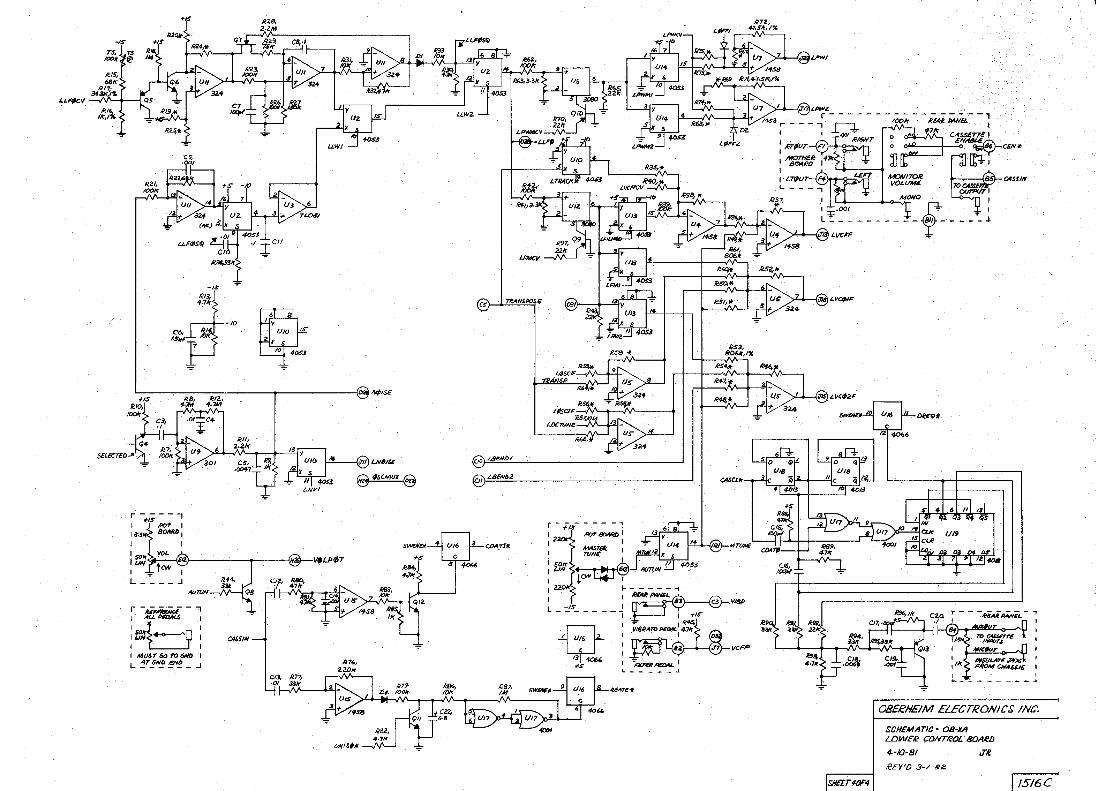
0B£RH£IM £L£DTRONICS' INC.
SCHEMATIC· OB-XA LDWER CON71cOJ.
S-/2. -BI J.R.
REY'D .3-1-.?Z
[l 5/6C:
-1$
'- ,.,-,,CV --'-v'V'--+--1
+,
OS, /$/ff
~-----------+---------i~'Mpr.s.-"~""~
li!/2, ... .,,.,
ins
.
c3,. I
. . 1c,; SELECTED . -:- /00,,.
I ~ , ... I L ____ J
""""" r - ,iim,;;a - -, :b..,,_,,,_, .·: I LIN ___.,_ I I I I Ml/ST GO 10 GNO I L ~7,!~ ~N!! _ J
c.S-) j -N~POfE
'.(1o)L86Nl>I
,er,)"-MNu
SWU/Efl CJMTt«
- - ,.... - ~ - - . I f ,<Jr f'OT-1 ~. I
I ~r
I - -, ~ · ~
~ ... 1kA'~I L-- - - - -'
li6AT£*
'CA&Cl.k
- --- ... - u- -,. - /a)K ~D!l/+4M d
.71< CA$S£T7£ I ' £N~CEII'*
L.I>---::=-, MOAl170Jl.
~
CASSIN VOJ.f/Allf.
MONO ~ £: -- ----0-f-----l
'>1--!-{MJ < V<#il.~
!SNEE TIOF4
OBEeHEIM ELECTRONICS INC.
SCHEMATIC - Oll-¥A lLJWeR CONTROL . SOA.el:J
4.-/0-8/ J~
REY 'O 3-/-BZ
[ JS16C
Lm(~
il". 1.
Y«.UME ~ -@v,tM
i~+IS~
~ P~.~MTUII
2201< I"lo/f Iii .._ Ct
-IS j]O+ .. 6 ' -:7,
. DUJ
CEIV*
f/S !Em I 1111
±6.1,JBLOS~ C2
t;ND(E9•i---+-~~ ......... ~~~
. .__.._:... -s
6..,,, Cf
~
R +s +SI.El)
470ql I6.8,' T IOV @ . cs GNO
+s.,
7o 4028
4-051
'A
BX 8863
SWL>2lf~ I I I I I - .. I I . _. I I -·- I I - ·- I I ... I
swL>3" t~ I I I
swL>4"~ 1 , I M , I M , I M,, I ~· r I I I --1
SWL>5 .. ~ I t I ·
swo6 ¥f~ I , I I ,,, r L ,,,. r · I ,,,, r I ,, .. 7 , I I ,,., 1
SWD7* ~ T I I a,o I I -- T I _,, T I A• ! I I ' n~ I
I I I (E4) SW.tNDtl
1SW6Mf,t1
74LS42
r-~~~~~~~~~~~~~~~~~~~~~~~~_li,~ANUiiH
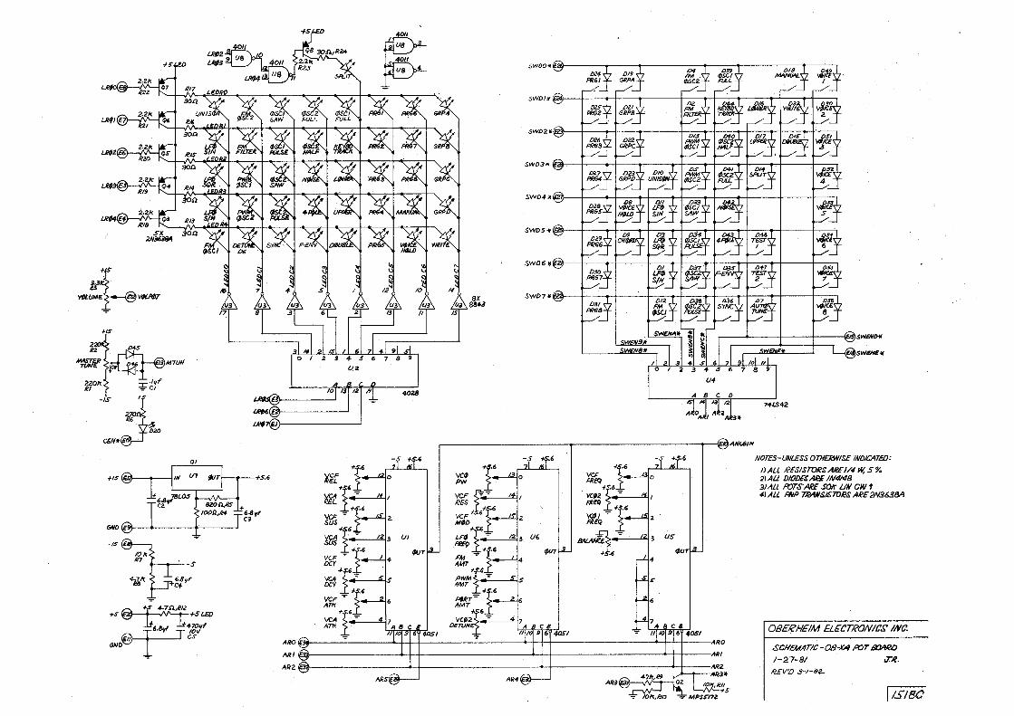
NOTES-UNLESS 07H£RJNISE 1NO/CATE£J:
!)All RESISTORSAl?El/-1 W, S% .:llAll 1)/0/JEGAN IN4/48 3JALl l'rJTSA£E SOk LIN CW t 1-IALL fflP 7:eAN.SI.STD~ AR£2N363BA
0B£RHEIM ELECTRONIC.r' /Nt!
:~I - 1 l! I - • 1 11 • 11 I : .SCHEM/ITIC~OB-XA !'OT a:J.4RD
1-27-81
leEV'/J 3 -1-ea..
,T.,ll.
AR-f
[ l.$/8C
I
I
r<' s, -!- ' lf"'
ONLY*
I. I
-------~@ TNAIISPiJSE
I r ®
~~+IS
rt!•~ .,.
osc z. LOW
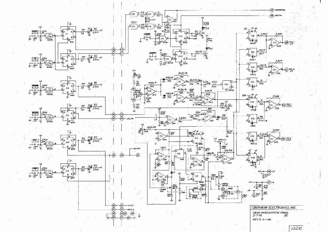
OBERHEIM £1.ECTRONICS INC.
08-xA MODULATION PANEL 2- 7-BI J,€
R.£V 'D 3-1- ez.
I /5 2 /C
J .'~

(BU<)'j~ (GM)
(WHT)
90-/.30/180-260 W'IC S0-60H:..
,... - - - ,
REAR VIEWS
IN · a ea • ~ o;o
2N30SS 780S 79/S
.+
!:3300r,,1',C9 W02M _Jsov
+1± 2200,,,,,, .cn 'sov
ca 6.8~ F ;;:r 7MT~
+ 3300~,C8 2SV
- - ~
·~{' 4..871<, /%
4.71<, IU2
ir,
S,621<,,</9 /%
'>c.'lf, r2 ~I ER li,/1/f ,RIO /'I.
:t +,s,,,,C6
OBERHEIM ELECTRONICS INC.
OB-XA POWER SUPPLY
S-27-81 JR A"EV'D 3 · 1·62..
f 15/SC
f3 D3 ~ R102 · Tl TS i {J9' m C) D4 RH IRZ2l DS ~ c::J
D = ~ D = ~ g Cl §la Cl40-.!:l Ii l1IZD rii: g 8 [@ ~ i, ~ B cil1lP IRN1 Bl ~ [jc,1[] '!lfll ~ If'; ll!li5J l!Z'll o3Q R 18 rn "'
~ Ul. ll ~ U2 ffi • m lli [@) ~I US 3 m~m®l;J~ @t~ ~ arJ ~ [filJ 11M ~ c~o "'4ID B_l05 " r--J!rl ~ [H5J CG) ~ (C]2) B Jl~ ~ IRDI IR25I ~ c:J Seo L_J
@] ~ ®J = ag ~ U4 if' ! ! ~~ R~rr §3~ ~ IRZJ @ ~ ~ ~ cil a:m !:J ~ u6 lllZ3 El 1111111 ~ Oa4 [! \'.:lJ ll!O !!I ~ !!I ~ IR2lil Iii~ ~ 11m1 i!l = rn
[lll1] [1!18] . ~ ~ ci80 lllill JI e a I U13 s ~ 6 QI U14 s ~ r n B1 ~~2 LJ r n °1[ n [1 t::=jo 6
C35 C36 LJ
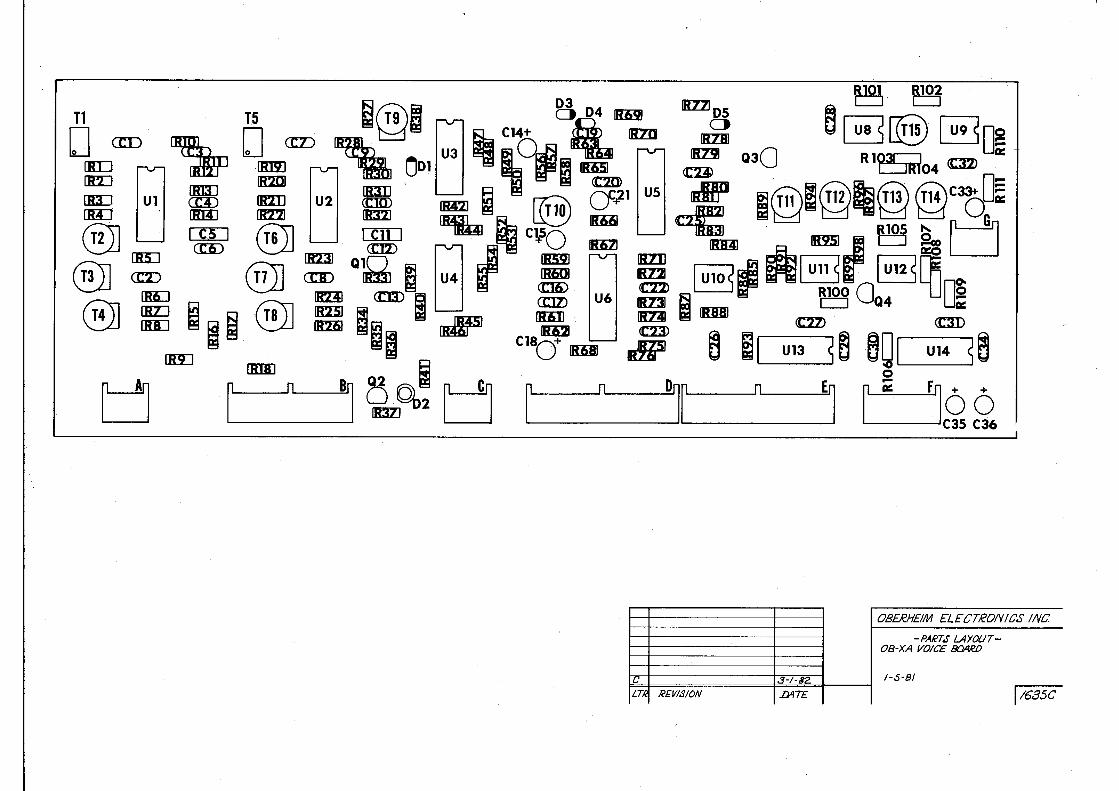
OBERHE/M ELECTRDIY/CS INC.
-PARTS LAYOUT-08-XA VOICE 8QAefJ
C 3-1-62 I-S-81
LH REVISION .D4T£ l/635C
D
· (
IF I IE 11° I D
B !LEFT SIDE
LOWER ONLY • UPPER ONLY •
la I
~ ~ ~ . ~
~Yi'~ ~- = , r.:'\ 00 0 0 -~ ~ [ilaa! •. 1 J•r:IO~~ U4 I~ V V !Rll• ti mmi J
112 [J~ D1• IK23le
Cl I,-------,EI
c., J · / -t,i::.
LTR REVISION .lJATE
D
IK3DI +c4
aaa~·r, 11[31) Q• LJ cs
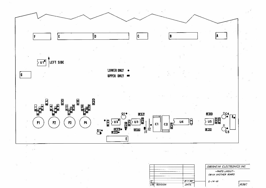
OBERH£/M EL£CTRON /CS INC.
- PARTS LAYOUT-
08-XA MOTHER BOAR!)
2 - / 4 -81
l16B6C
I(
D
C42
0
I xl
Qc•1 IRIBJ
@)
1 u 126 s Cu:m:3
t12Q c13CX)C14 O c1s
Rl~~ C ~ R~U[rm .
Rlli?lnoi 1 u13a 5 ~ ~
.. · R 10o01
.u 139 srrT u 140 s
I U101. 1 IRBl Ci)
<m> 0 8 « 'o' SW1
I uns S
~ ~· ~ e . . 1 U141 s B a e a e e RB
o · CB]
B iul [J tJ LJ
1; [=]
~~ [:]
B B B R20 ~ e:=J 1 u 124 s
~ ~ ~ U 136
n, .• ~ ~ ~. I '"' I
a:n <DD am cm ~ ~ ~ 9[]
~ <DJ ;iu I """ l
I U106 {
[ u101 =:s
I U108 S
I uno 5
I um S
I Ull2 5
I u 113 {
1 u 114 5
Q2
~ 1a Q c26
113)
Cl~R112
I U116 5 1 U142 51 U143 s I U144 5 1 U145 5
!I U117 S li = 5 ae e I U146 s a e a e , U147 ·s ae ~ 111!1.iJ (13
I U118 S ~ w·ffl (J C36 . . ma. (J n ::::-04 ° iB2Bl M :la QS I[!]) . . RIB]
. [r30 ju14956 I U149 s BS ~ n I u 119 . s . R32 IIBil Jr ··Rfni
I U120 s TI1
D !u1s2s~S U153 sea ~ ,Ui54~m~ , UlSS S
Tf ~ C3i Ra. rjllf!'13
! .u1s6 5\- ·.~ ~ . I U157 S I u 15.9 s . ~~ , U158 sm .~
1115:1
I U121 5
IR35J QB 0
I U122 5 ~R
I · 34 :u123 S OD
~, - U-16-0 ~S ~ U 161 S
lll3lil
I U163 5 DR56 I u 162 5
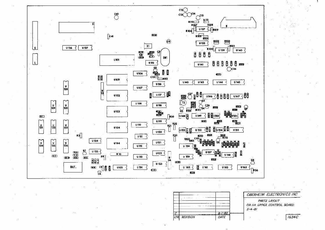
0 8 £RHEIM ELECTRONICS INC'.
PAR.TS LAYQ(IT
08-XA UPPER CONTROL BOA!c!D
S- 4--81 () 3-1-82.
LTR. REVISION DATE I l634 C
~ Q4 Q R101
tlD
.L Oa1 Oa2 Qa3
cr!J ~ (Cl%) IB'.ZII C90
~ fu:J 0R10 ""'l;1 <C:D i u20 S ri -----1 @) .~ j1Rl2 t)El i D [ml
I.--u 33---.s B ij1
ij
l
@ <rD l.t'n . ccm ~c:ii;i l!l am anO » e!i313 ij
B 0 .. ·"1 a= IIDII @ IRl5l R87
as O I @] IKIZI O ju11I 0Raa
a60 ~ 11ml ~21 DC15
Boa· ,I Bo=!l.B 111311 a:v Qc9 IRll!a (Cl]) Q70 ~ lmJ
111351 lll!Z2
if ""'I I I
I U23 5
I
I ~I U24 S I I U25 ~ I I 1_ J
I U26 5
I U27 S B =~ DDB19
IB3Zil Ii.JI IBl3I &1'13
oaa ; EJ T fui;] .: E()c11 ~44 lllilil ~Q9 a:l!>
! Rl54 !
I U28 S
alil ~ 1ml a:m.
-! BAB ii; 1,,, ~ am m:o mm I ~
C
~ODD R6~B mo
(Ja10 a IIIZ3
\EJ i I! 111211
I U29 5
I U30 S
I U31 5
a:2J> I U32
Ql4 0
OB~£ tle it1
I U34 5
I U35 s ~ Qc31 (rs'
~ ~. g ~Qc32
Ql5 ~ Q16l.)-!='
c::JRIOS
t3\Aa1 ! C59 ! !C60!
I U38 s I U39 5
a:ID crnJ I C63!
!C64l
! C65l
!C66! I U40 5
B B 8
Cli2)
CD ca ccm CZD en CZ3 IC7l[)
~
CZli> ~
CZ!D
B B
C,'
B 8
CC7> <CD ~
<CB
«:22).
<CD m <CJD
Rl02 c::J
Qc310
BBiB B ~B
()c44Qc46
czg
CID CllD Cl7)
CD CD «:6 cs CIIZ)
~
B
csB()
Bl R14c:::::J B ~142
~
43U7 Rl 45 Rl4
BR147c:::::J 8 c::::JR148 RsB149 U7
Rl~151
.::1- 1- ac:
LT!c REVISION DATF '
6
H
B
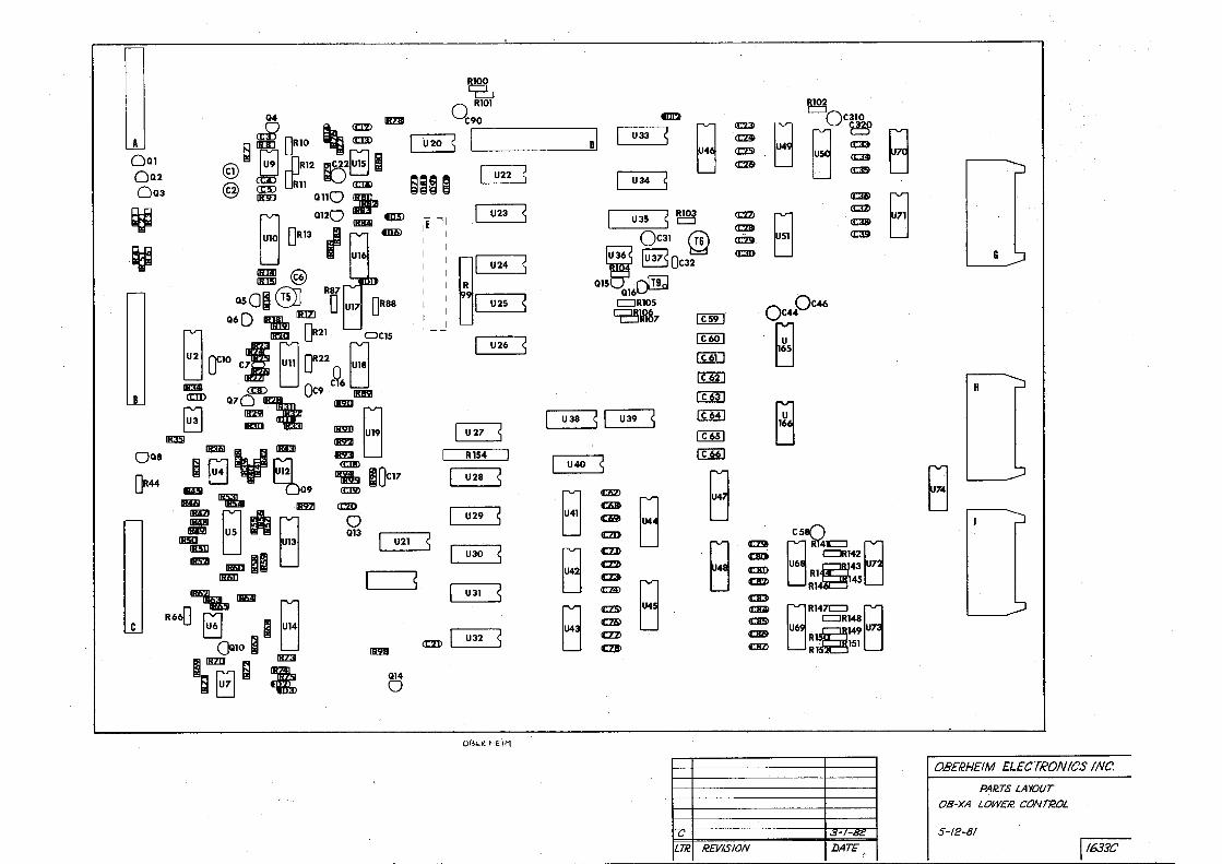
0B£RHEIM ELECTRONICS INC.
PAR.TS LAYOUT
OB-XA LOWER. CONT/20L
5 - 12 - 81
I l633C
~ c· :···1 D~5 ~-··: Dl.6 ~--•
: : u : : D : L-- • J : •••• J : l. • ••
017
D
n .,, u C:::, 0~ 035
c:::,
: : : : I I I 1
..... J I I \. ... .: ____ , ~ :----i r~
~80 0 B
=•1 o•• uu
018
D
D36 ' 037 038 c:::, c:::, c:::,
r -·-1
' .....
0 I I
,··, R6 D20\_ .' C:::l
019 : ---: , 021 --- ·, D22 ;-·- ---, ,-- - -D23 , 024 •
... ---D25 , , D26 027 028 029 030 031 ;----. ,- - --
032 I
D : i D
039 c:::,
0 ' '
D .
040 c:::,
... ...
D i D :
"041 c::::,
042 c:::,
D i j D n D n D D 1 __ _ _
02 0 0 0 0 0 Ul
D
:::~GOQQQ ~Q ~ Q .. ID ..... , 0 QB Q 0
OJ Q4 OS. Cl6 07 Q R2J
~ Rll ~ Rl2 OOOOOCJO~ . = = . ~ DODOO .,. Rl8 Rlf (120 R21 R22
-· OBER.HEIM ELECTRON JCS INC.
PARTS LAYOUT
OB-xA POT BOARD #I
12-10~8/
C 3 s f.-82
LT/2 REVISION l)AT£ I /6~C
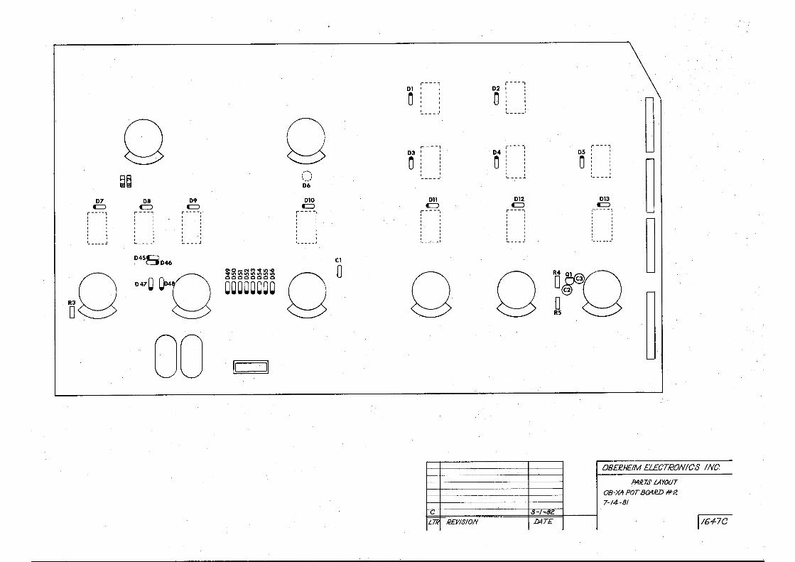
D7 C::J ----,
' '
- --- - J
0 ~~
D8 C::J .-----,
'
' ... - - - .. !
D45BD46
D9 C::J -- --,·
___ J
oO ·q
0~0 00
0-0-NM .... .n,O .... ll)ll)~W')W')W')W') QQQQQQQQ
00000000
II II
i----Dl '
0 j '
0 ,..... -- - 1
D3 '
0 : ' ' ' ,·-,: ' o I ._ ___ _; .. •
D6
D10 Dl1 C:> C:>
r-----. r - --, . ' : I . I . ~ :
' ' ' . , _____ , '- - --- .J
Cl 00 0
c;
L.TR R£YIS10N
.. -- -D2 •
Oi
~ ' ' ·-----·
;---- , r ---D4 , . D5 : 0 I • 0 i ' .
~ o I
' I
' ' ' ' . ._ ---.. ·-- --
D12 D13 C:> C:>
r--- - 1 r ·- - - - ~
I ' ' ' . ' ' ' '
~ ' .
' . ' ' : ' ' .
L .. - - . t ·-- ----
~~o 0 R5
0B£l!H£IM £L£CT!cON/CS INC.
PAiT.5' LAYOUT
···-··· OB-XA POT B04.€D #2.
7-14-8/ !J-1~82
D4T£ .. l/647C
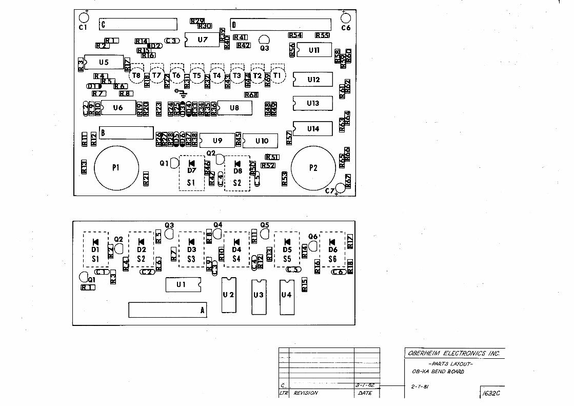
0 . c1 le I DlL lo I Q
ad"jD ~ <!::ID ~ u 7 ~· 1'l£ 0 IIIIll 111:551
~.___? _u_s ----IIE;I.~::.~,: 1~:-=-.-,: ,~:::, :-::_: :-::-; :----; ,---:3 ,----, ~ ~ . un j U IB:lJ, ~Ta T7 T6' "rs' ,,r4' 'Ta" ,;:;-i i-;:--, T ~~----i----&-j-----B----1----!;1·-.!_,, .___r'--? =u12=J ~
ew u6 1~~ a ~i~a~~~~ us 1 11 ~ Ul3 1 B ~ le I liE!J;lf<B!! ~ u14 I fl ~ ~ --- ~i~~? U9 . II? UlO I ~ ~ ( Pl ) ~ a19---f~9---~~-~= (.,\I
~ . Sl ra e: S2 r11 a ~---- ___ 1 :__ ---- _J
Q3 Q4 QS
:--~--: Q2 :--M--i~o :-M--:~O:--M--!~o :--M~-: Q6:--~--:
i ~: ~o : ~; : ~ i ~: : ~ ~: : ~ i ~: : !0 : ~: : ~ ·--ciS a--~~ , ____ J~ , ____ JI ·--rn !--~ ~ ~ , Ul s 8 8. B· ~
U 2 U3 U4
I Al .
C
LTR REVISION
OBERHEIM ELECTRONICS INC.
-PAR.TS LAYOUT-
08-XA BEND BOARIJ
.8-1- ac. 2-7-81 I 1632C .DAT£

A
I 11
[RI] CTI)
~
J [Jra] Ul
[@ [RU ~
[ns=J
s I +
) I )
C7 '
I
. +
B C D
11 II I +QcJ
[BZJ en) C4 HJ
!R2:J U2
[@) 0 +
[R]D] IRl2J !R1IJ
§ s +
cs ·O+·· 0
+ C6+ I
cs C9
I
Cll
F
H
+Qc10
S-:i . ·~
~ ~ s:s ~ ·
~ l.lJ Lai
~ ~ ~ ~
" . ::::i ::,... ~ ~
~ ~ ~ A! ~ ~ ~ ~
~ ~
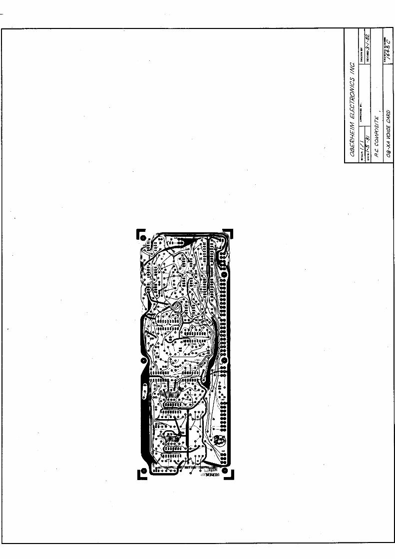
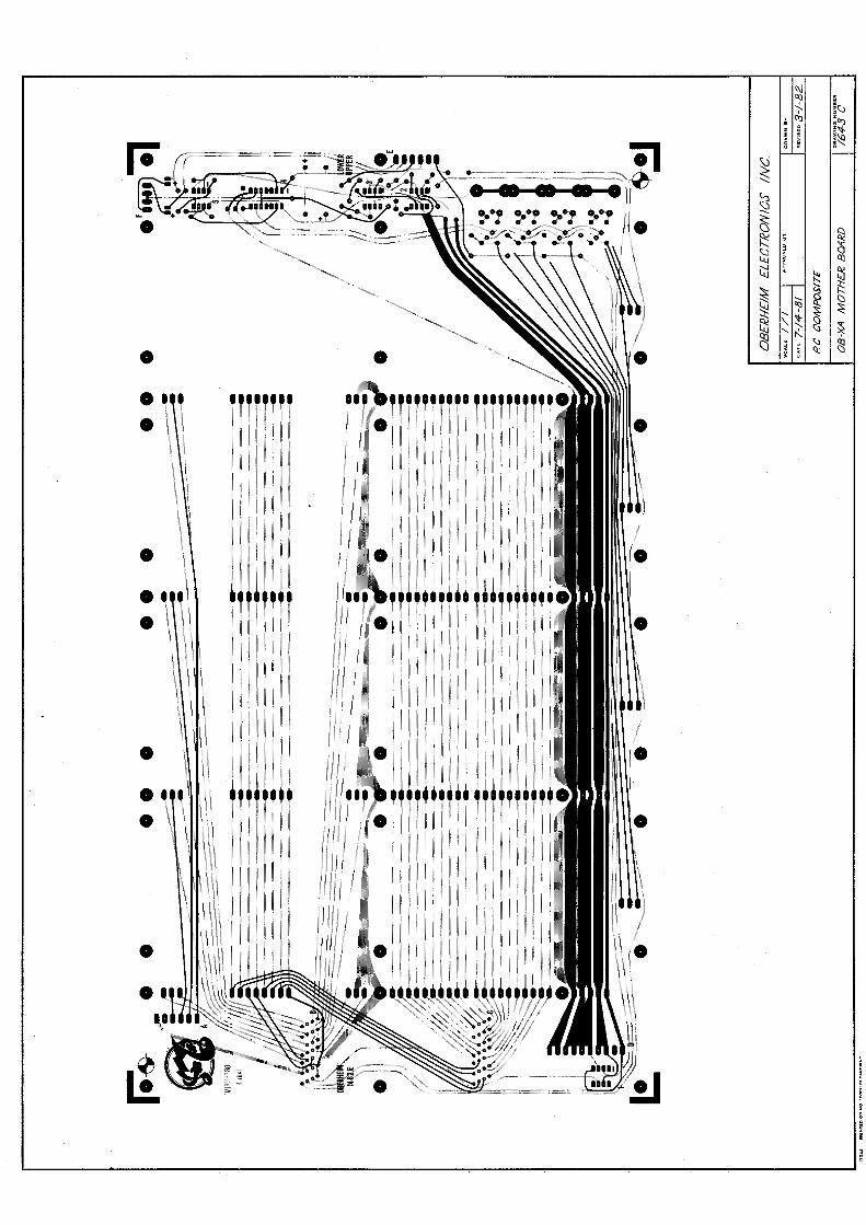
• .. ' I i • l \
\ l ,, I l i
\ \ \ !
'1 \ l ! \ i
\ I . \ • ~ ~l . \ \\
•
\ I \ i I l \ '\ \ I \
\ I ! \ \ \ \
\ \ ! \
\' . ~ ~ \ . \ \ \ t
I I
\
\ \ . i i \\ I \ l t
\ \ 1 \
• •
iif'1• iiif 1 11 I I ii I I I I .• 11· l I· 11. 11 i 11 I
111 i I. I I I, I i i 11
ii Ii I 1.: 'I , , I I I J, '" . I . .
I' 11, 11 1.·. 1
I I I ii f I l ! 11 I I
·1. ! I!.··.·. '·· ' I ! i I I I
, UU1 1
! 111 ! ! I •
! ·11111 I! I . , 11 i i I. , I I ·, 11 l I I 11 I I I r.· 1
1 .' .I I I
I . l I I ! I 111111 t 1 ii! 111 I I I 111 1 i 11 l. 111 1 I, j I . · 111 j I !I I ·. ! i I . I I I I ; I 111 1· 1 1 I• i I!; Ii
11 i l i. I I; I] ! ii I
·-1,UHU r 1.11 • .. ' I. I I l 11. I
111 ! i I I I. 11· I l i I I I I I Ii '11· 11 .. 11 I . 1· I!
I I 1 1 I 11 I i. I
·j ii I ! 11 I I I 11 i
'l 11 I ! I l I I I l 1 11' 11
j f i I
I I I I I I ! ( I l
I 1 /! d r/f j . 1·/ ii; i ! !
/// di HI I
I/ I I 'iJ i 11 1 I Ii! I I{ I l 111 I !f f I q: l
11 If /. .i I n 1 1
ii !I ' f I ff i
)/ 11 1
Ill!/ lJ l/ i 'li ' ' 11,/1 !111 1 I,!!/ Jf!U
11 If I I lid 1''1 ' 111, !
I/ !/I
<:\I ~ !tl ';'-tll ~"1
!'Sj.
i~ ~
~ t3 --... ~
~ ~ ~ 4.1 ((J
•
i:;j ~ ~
~ ~
;;i t.::: .... ~ c::i
~ ~ ~ "- I ~
~ ' ~ ~ .... I( ~
~ ; <..; ~
~ ~ Q,:
• \
i
l
/ to I
• \ \ I
/ I
to I
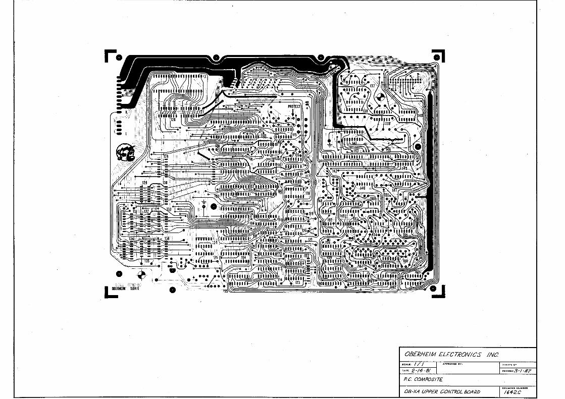
-;;,,;.; :;; \t}rn38il l.:1HEIM 1504 G
0B££H£/M ELECTRON/CS INC.
•<•U, I / I
"" ' ' 2-/ 4- -81
P. C. C'OMPOS/7£
OB-XA UPPER CONTROL BOAWJ
R£ Vl6&:0c'.3 ..,. / -82
OR AW ING N UM.iR
/ 642C

~ '~ -;. i()
? ~~
~ :~ '-l ~ ~ ~ ~ CQ
~ ~ I-;:: ~
~ ~ ~
l..i.j ~ ~ ~ ' :§; ..... !3 ~
Qg
~ '.:3 ,' ~ \~ ~ ~ ~ ;~ \:i ~
~ ' Q.;
• .J
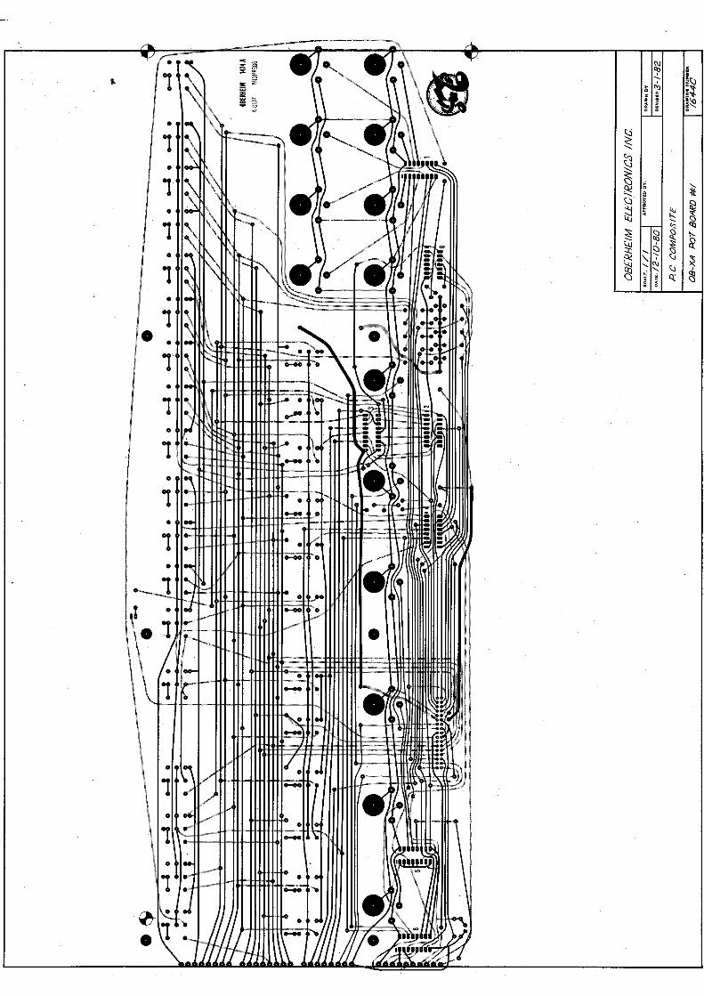
- .. • ..., II
--1 ..... "~-~-t+t--l..++H-I,.... • --.J
C\J ~ -' ~ II) . ~
I l . . >->-
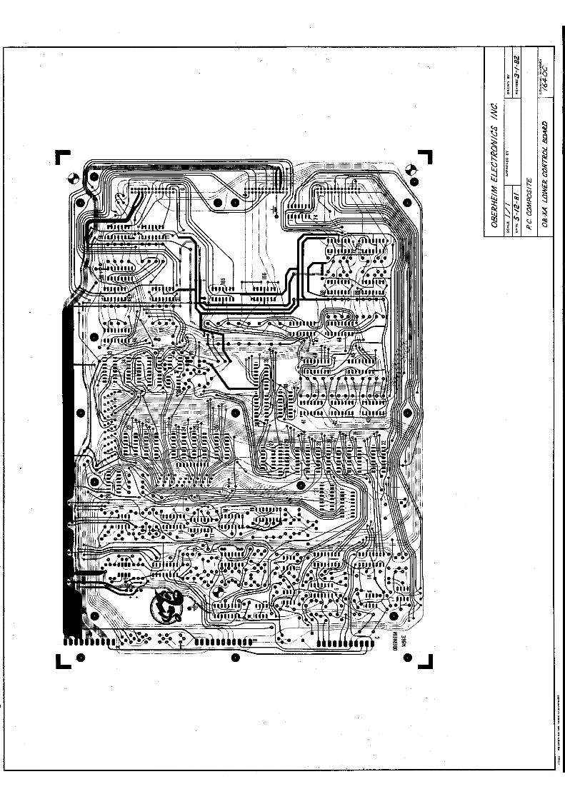
~ ' ";,, ;r__i
7 i() ~"4-
~ i~ ~
~ t1 i ~ ~
~ cl
" ~ ~ ~ ~ 1:3
~ ~ ~ ' ~
' ·~
~ ~ ~
~ \~ ~ ~ '~ <:.3
~ i "' ~ . Q.; ~ 0
L• • .J
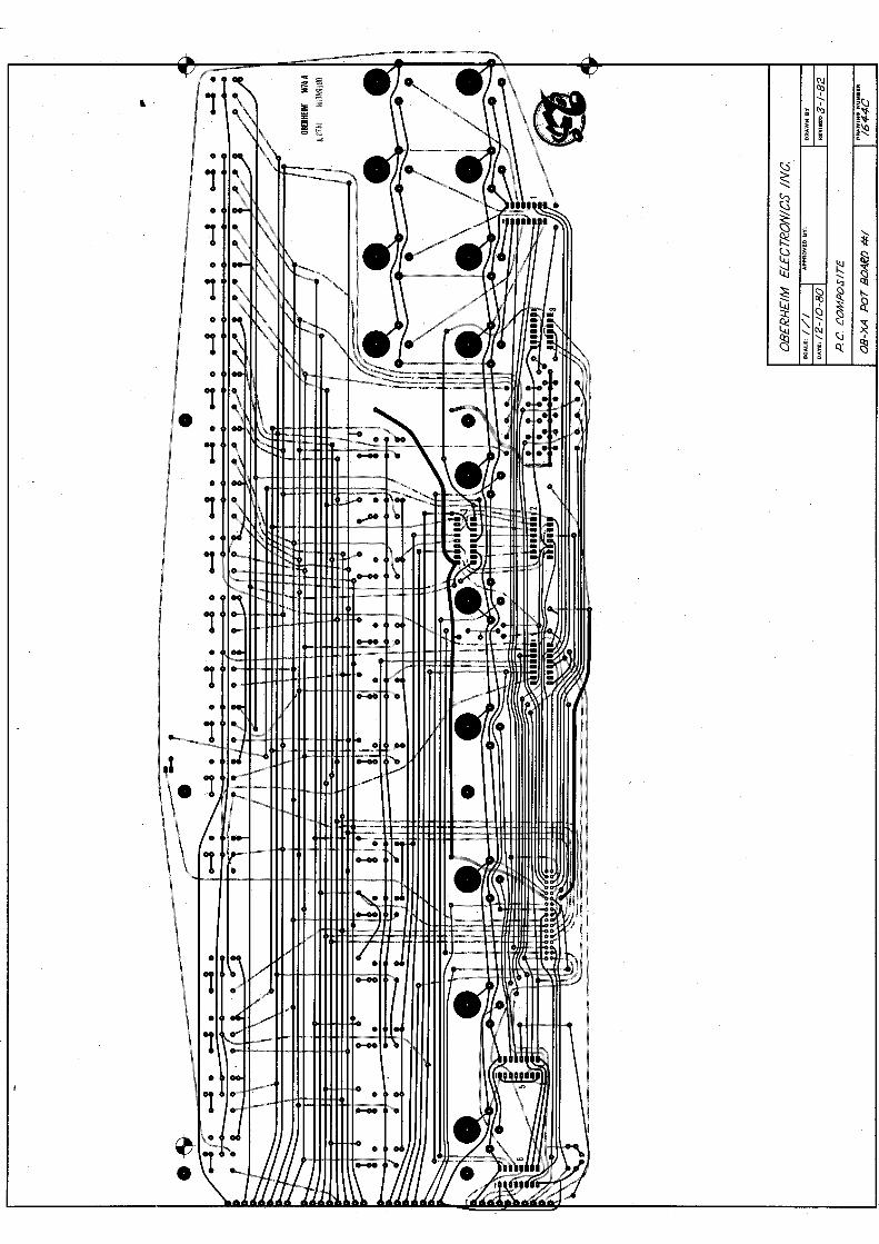
- . . -1 I.J~ J.W-1+1-+ttttttmr • V.
- 'O • .._ V
--1 °'...u:=:."-'H+t-t+l-+l+~k • --.J
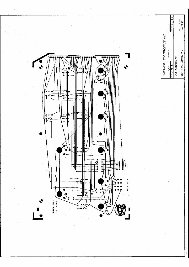
,
• •
•
I
L! l
i ! i
-------~:

~ ~ s iC:l
' !~ = i~ ~ f '
l:.j
~
~ ~ ' ~ :ii t,;::
! ~ ~ l.j ~
~
~ ~ ~ ~ ~ ' " ~ 'l:j
!Jj· \. ~ '3 ~ '<.\J \:i ~ ~ .. " ' • ~ ~ ~

CJB£ R.H£1M ELECTRON/CS INC tCAL.i : ///
om /0-4-8 / rtCVIH03-/ -82.
P. C. CCMPO.S/ 7£
CltAW ING NU•HI.R
OB-XA 8£ND B04/W #2. / G39C
1nca a NUHTHI OIOIOO. ,_ ._ ... .. _ ....

<N ~ ' '1 ......
7 " ~ s '-:::
~
~
~ ~ ~ ~
11'.l
~ :.. I..;:: ~ ~ ~
~ Qj
c,.;
~ ~ ~ ~ ~ i ~ ...... '\J
lli "'';' ~ ~ ...... (\J
~ " ' o:j ~ ~ Q..: ~ ~
·(I ii , ;;. . ..•. !S:!
.. ~i
•
,· . r t ~ b r Ii 11 r, ~
t I' r r t • ~.
L
WE NEED YOUR HELP If ~ find errors in this manual, or feet that needed information is missing or unclear, please write ~r comments on the reverse side of this form and return it to us.
Oberheim Electronics, Inc.
I. I ----------------~----~d~~~im _______ -i-11~,---~-~ f MAILED IN THE (, UNITED STATES
l t l r i
f ' l t I
I· I
1 J I
Attn. Publications Dept.
BUSINESS REPLY MAIL FIRST CLASS PERMIT NO. 62816 LOS ANGELES, CA 90029
POSTAGE WILL BE PAID BY ADDRESSEE
OBERHEIM ELECTRONICS, INC. 2250 South Barrington Avenue Los Angeles, California 90064
}-----------------------------------------------------i Fold Here Second
~ l J I 1 1 ,1 .J J ·1 ·:1
1 11 :i ,·1
.I 'I 1 JI
" ,, Seal Here
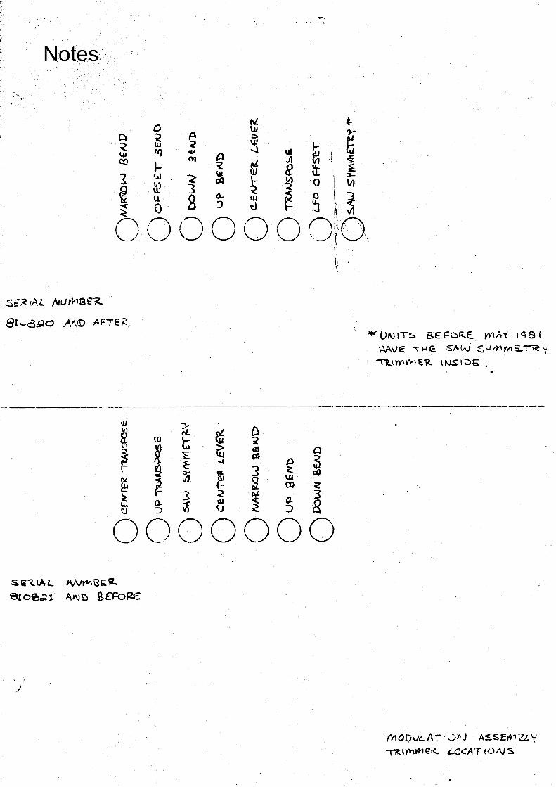
.Sf~ /AL A,Url-1St~
· ·8t-...o4'lO 1''1\JD AFTER .
·- ---- ---·
l&I ~
J ~ UJ t;
~ ~ E ~ " ~ ~
~ ~ i vJ
3 < ""'
0- < di
"' :, V) ~
~ . .. .
~ .. ~ w ~ g ~ J1 v, i ,f "1 e tt: -~ t ~ · o_ 'l ~-w -< O 3 cl ~ ~ ~ ~
0 . 0 r'\_iro.· .. \ ... ·. I " . . ' '· ,, ·t · · .. ·. . --- \\ . · ..
0 i Ill p)
tl 3 ~
~ \U 00
~
! 0. :,
Q
~ c:Q
< 3 8
u
*'UNITS. B€ ,::cR.£. VVIA-Y I q S I AAve ,l-'-e SAW ~'l'MW,I:...~"
~\}'Y'W°'E'R \tvStt::>!;. I
·- --- -----
0000000 SE'.1..IAL.. >VV~ijf:~
e1oe~1 AN~ BE'Foi<e
j
1'1-1 ODvL A Ir •Jf.J ASSEY>1 UY '1'"R \ mm 1N.. LC<AT 10 /\J s.
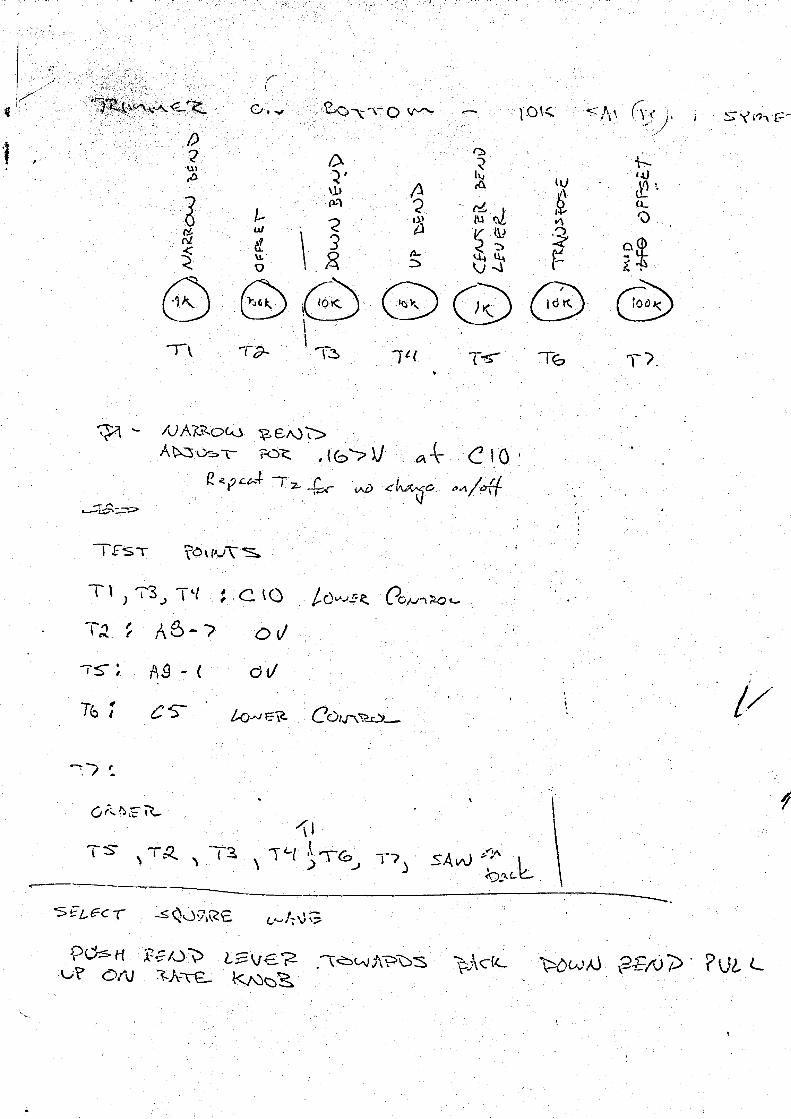
·,r . ( . ' ·,
, ()\<.. · ·'5)\ \ 0~<)· .,;
TEST
....,-., , . , -
D .·u1 ,· ~· I)
fl \l)
i· P.."\ ~ . ' :: ' , ... < 'tl w /ti e. \ '] < \I. ·B 11-
·~ · Q ~
8 8) ~ 8 ~\ 'Tlr
I \.'.!) -r,,
/J A7,.cR.ow ~ i::10 0 A~ .IJ"_;, \ FOC::. I f (::;"--;> V
.. ·r::,
< Ii., ~
-{-!;, tJ IU •
~ ·
IV ".:)
'-4 lt,\ v ··--.l
G) T~
P0s H t:;1..)v. Lf=VE.:2- .~.6wJ\?"t:>S ~_;\c((_ :v? Ot'\J 1-A""t£... K.NC)s
-\--qJ
hJ ~ •. ~ u..
'v ti\
1 ='i r- i. .
G B T~ '"f)_
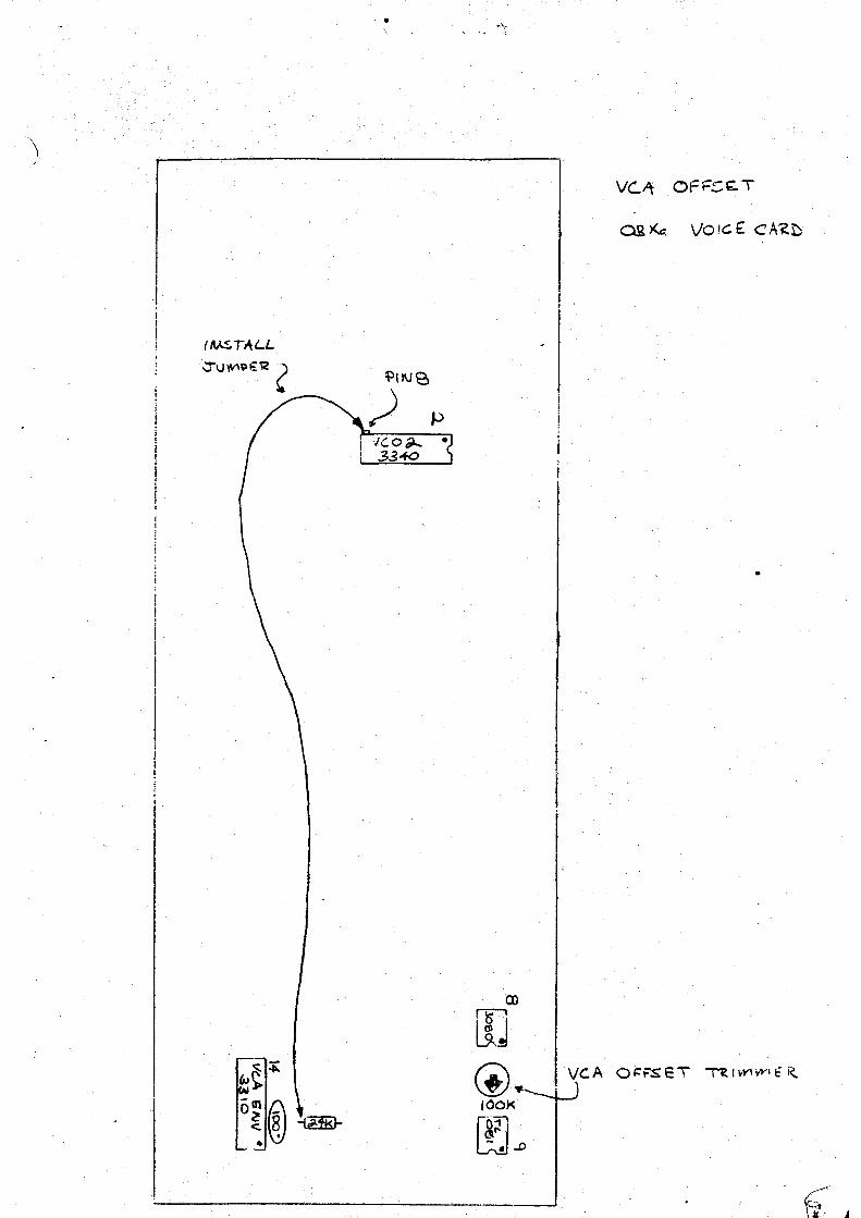
... ,,_.
I .
I (MST,\LL
JUY-"~€:'12 (
•
:;c.o ,-.. • I 33..fO

)
)
i I ,. i I 1
j)v.;i,i t-,.., f' t. •..: i .4--,. ·rvtc --~ ~,~r. '·"/' ~·
~PL.t?~· ,. 1\JVr\<.a[)-'4
bND - ~ i
; @ ;
· - ~ - -.;.;.:
i .
lNIT"
ype -~ w_ .· --~- · --· . . H __ r--m_. AK ._,,.., \ • .) (•\
' J ·" ·----: \ ~ -~~ 1001<. iOt<.. ~
.r-·· Ql\O~ ! r-· . . ··-i1 L v, o~ .;2 _ ___ j
<,., r::· -··-_-. -· . .,_ . . 1 40$3 :
L - ---·-- ,, _ _ j
~PU~ •J . [-- .. -~---· ·· ... . ~_f ;l. .,.~~J
:03-XA vo,c..E c.A·Rt /·(·· ·
'
· .. ·~ .
/ /
/
Related Documents