CC/CV and CC Models XMT 304 (230/460 And 460/575 Volt Models) R Processes Description Multiprocess Welding Arc Welding Power Source OM-2208 175 493AF May 2005 Visit our website at www.MillerWelds.com

Welcome message from author
This document is posted to help you gain knowledge. Please leave a comment to let me know what you think about it! Share it to your friends and learn new things together.
Transcript

CC/CV and CC Models
XMT 304(230/460 And 460/575 Volt Models)
�
Processes
Description
Multiprocess Welding
Arc Welding Power Source
OM-2208 175 493AF
May 2005
Visit our website at
www.MillerWelds.com

Miller Electric manufactures a full lineof welders and welding related equipment.For information on other quality Millerproducts, contact your local Miller distributor to receive the latest fullline catalog or individual specification sheets. To locate your nearestdistributor or service agency call 1-800-4-A-Miller, or visit us atwww.MillerWelds.com on the web.
Thank you and congratulations on choosing Miller. Now you can getthe job done and get it done right. We know you don’t have time to doit any other way.
That’s why when Niels Miller first started building arc welders in 1929,he made sure his products offered long-lasting value and superiorquality. Like you, his customers couldn’t afford anything less. Millerproducts had to be more than the best they could be. They had to be thebest you could buy.
Today, the people that build and sell Miller products continue thetradition. They’re just as committed to providing equipment and servicethat meets the high standards of quality and value established in 1929.
This Owner’s Manual is designed to help you get the most out of yourMiller products. Please take time to read the Safety precautions. Theywill help you protect yourself against potential hazards on the worksite.
We’ve made installation and operation quickand easy. With Miller you can count on yearsof reliable service with proper maintenance.And if for some reason the unit needs repair,there’s a Troubleshooting section that willhelp you figure out what the problem is. Theparts list will then help you to decide theexact part you may need to fix the problem.Warranty and service information for yourparticular model are also provided.
Miller is the first weldingequipment manufacturer inthe U.S.A. to be registered tothe ISO 9001:2000 QualitySystem Standard.
Working as hard as you do− every power source fromMiller is backed by the mosthassle-free warranty in thebusiness.
From Miller to You
Mil_Thank 4/05

TABLE OF CONTENTS
SECTION 1 − SAFETY PRECAUTIONS - READ BEFORE USING 1 . . . . . . . . . . . . . . . . . . . . . . . . . . . . . . . . . . . 1-1. Symbol Usage 1 . . . . . . . . . . . . . . . . . . . . . . . . . . . . . . . . . . . . . . . . . . . . . . . . . . . . . . . . . . . . . . . . . . . . . . . . 1-2. Arc Welding Hazards 1 . . . . . . . . . . . . . . . . . . . . . . . . . . . . . . . . . . . . . . . . . . . . . . . . . . . . . . . . . . . . . . . . . . 1-3. Additional Symbols For Installation, Operation, And Maintenance 3 . . . . . . . . . . . . . . . . . . . . . . . . . . . . . 1-4. California Proposition 65 Warnings 3 . . . . . . . . . . . . . . . . . . . . . . . . . . . . . . . . . . . . . . . . . . . . . . . . . . . . . . .
1-5. Principal Safety Standards 4 . . . . . . . . . . . . . . . . . . . . . . . . . . . . . . . . . . . . . . . . . . . . . . . . . . . . . . . . . . . . . 1-6. EMF Information 4 . . . . . . . . . . . . . . . . . . . . . . . . . . . . . . . . . . . . . . . . . . . . . . . . . . . . . . . . . . . . . . . . . . . . . .
SECTION 2 − CONSIGNES DE SÉCURITÉ − À LIRE AVANT UTILISATION 5 . . . . . . . . . . . . . . . . . . . . . . . . . . 2-1. Signification des symboles 5 . . . . . . . . . . . . . . . . . . . . . . . . . . . . . . . . . . . . . . . . . . . . . . . . . . . . . . . . . . . . . 2-2. Dangers relatifs au soudage à l’arc 5 . . . . . . . . . . . . . . . . . . . . . . . . . . . . . . . . . . . . . . . . . . . . . . . . . . . . . .
2-3. Autres symboles relatifs à l’installation, au fonctionnement et à l’entretien de l’appareil. 7 . . . . . . . . . . . 2-4. Principales normes de sécurité 8 . . . . . . . . . . . . . . . . . . . . . . . . . . . . . . . . . . . . . . . . . . . . . . . . . . . . . . . . . . 2-5. Information sur les champs électromagnétiques 8 . . . . . . . . . . . . . . . . . . . . . . . . . . . . . . . . . . . . . . . . . . . .
SECTION 3 − INTRODUCTION 9 . . . . . . . . . . . . . . . . . . . . . . . . . . . . . . . . . . . . . . . . . . . . . . . . . . . . . . . . . . . . . . . . . 3-1. Specifications 9 . . . . . . . . . . . . . . . . . . . . . . . . . . . . . . . . . . . . . . . . . . . . . . . . . . . . . . . . . . . . . . . . . . . . . . . . 3-2. Duty Cycle And Overheating 9 . . . . . . . . . . . . . . . . . . . . . . . . . . . . . . . . . . . . . . . . . . . . . . . . . . . . . . . . . . . . 3-3. Volt-Ampere Curves 10 . . . . . . . . . . . . . . . . . . . . . . . . . . . . . . . . . . . . . . . . . . . . . . . . . . . . . . . . . . . . . . . . . . .
SECTION 4 − INSTALLATION 11 . . . . . . . . . . . . . . . . . . . . . . . . . . . . . . . . . . . . . . . . . . . . . . . . . . . . . . . . . . . . . . . . . . 4-1. Selecting a Location 11 . . . . . . . . . . . . . . . . . . . . . . . . . . . . . . . . . . . . . . . . . . . . . . . . . . . . . . . . . . . . . . . . . . .
4-2. Weld Output Receptacles And Selecting Cable Sizes 12 . . . . . . . . . . . . . . . . . . . . . . . . . . . . . . . . . . . . . . . 4-3. Remote 14 Receptacle Information 13 . . . . . . . . . . . . . . . . . . . . . . . . . . . . . . . . . . . . . . . . . . . . . . . . . . . . . . . 4-4. Optional 115 Volts AC Duplex Receptacle And Circuit Breakers 13 . . . . . . . . . . . . . . . . . . . . . . . . . . . . . . . 4-5. Electrical Service Guide 14 . . . . . . . . . . . . . . . . . . . . . . . . . . . . . . . . . . . . . . . . . . . . . . . . . . . . . . . . . . . . . . . . 4-6. Connecting 1-Phase Input Power 15 . . . . . . . . . . . . . . . . . . . . . . . . . . . . . . . . . . . . . . . . . . . . . . . . . . . . . . . .
4-7. Connecting 3-Phase Input Power 16 . . . . . . . . . . . . . . . . . . . . . . . . . . . . . . . . . . . . . . . . . . . . . . . . . . . . . . . . SECTION 5 − OPERATION 17 . . . . . . . . . . . . . . . . . . . . . . . . . . . . . . . . . . . . . . . . . . . . . . . . . . . . . . . . . . . . . . . . . . . .
5-1. Front Panel Controls For CC/CV Model 17 . . . . . . . . . . . . . . . . . . . . . . . . . . . . . . . . . . . . . . . . . . . . . . . . . . . 5-2. Front Panel Controls For CC Model 18 . . . . . . . . . . . . . . . . . . . . . . . . . . . . . . . . . . . . . . . . . . . . . . . . . . . . . . 5-3. Meter Functions For CC/CV Model 19 . . . . . . . . . . . . . . . . . . . . . . . . . . . . . . . . . . . . . . . . . . . . . . . . . . . . . . .
5-4. Mode Switch Settings For CC/CV Model 19 . . . . . . . . . . . . . . . . . . . . . . . . . . . . . . . . . . . . . . . . . . . . . . . . . . 5-5. Meter Functions For CC Model 20 . . . . . . . . . . . . . . . . . . . . . . . . . . . . . . . . . . . . . . . . . . . . . . . . . . . . . . . . . . 5-6. Mode Switch Settings For CC Model 20 . . . . . . . . . . . . . . . . . . . . . . . . . . . . . . . . . . . . . . . . . . . . . . . . . . . . . 5-7. Lift-Arc TIG Procedure 21 . . . . . . . . . . . . . . . . . . . . . . . . . . . . . . . . . . . . . . . . . . . . . . . . . . . . . . . . . . . . . . . . .
SECTION 6 − MAINTENANCE & TROUBLESHOOTING 21 . . . . . . . . . . . . . . . . . . . . . . . . . . . . . . . . . . . . . . . . . . . 6-1. Routine Maintenance 21 . . . . . . . . . . . . . . . . . . . . . . . . . . . . . . . . . . . . . . . . . . . . . . . . . . . . . . . . . . . . . . . . . . 6-2. Voltmeter/Ammeter Help Displays 22 . . . . . . . . . . . . . . . . . . . . . . . . . . . . . . . . . . . . . . . . . . . . . . . . . . . . . . . 6-3. Blowing Out Inside Of Unit 23 . . . . . . . . . . . . . . . . . . . . . . . . . . . . . . . . . . . . . . . . . . . . . . . . . . . . . . . . . . . . . . 6-4. Troubleshooting 23 . . . . . . . . . . . . . . . . . . . . . . . . . . . . . . . . . . . . . . . . . . . . . . . . . . . . . . . . . . . . . . . . . . . . . .
SECTION 7 − ELECTRICAL DIAGRAMS 24 . . . . . . . . . . . . . . . . . . . . . . . . . . . . . . . . . . . . . . . . . . . . . . . . . . . . . . . . SECTION 8 − PARTS LIST 26 . . . . . . . . . . . . . . . . . . . . . . . . . . . . . . . . . . . . . . . . . . . . . . . . . . . . . . . . . . . . . . . . . . . . . OPTIONS AND ACCESSORIESWARRANTY


OM-2208 Page 1
SECTION 1 − SAFETY PRECAUTIONS - READ BEFORE USINGsom _3/05
� Warning: Protect yourself and others from injury — read and follow these precautions.
1-1. Symbol Usage
Means Warning! Watch Out! There are possible hazardswith this procedure! The possible hazards are shown inthe adjoining symbols.
� Marks a special safety message.
� Means “Note”; not safety related.
This group of symbols means Warning! Watch Out! possibleELECTRIC SHOCK, MOVING PARTS, and HOT PARTS hazards.Consult symbols and related instructions below for necessary actionsto avoid the hazards.
1-2. Arc Welding Hazards
� The symbols shown below are used throughout this manual tocall attention to and identify possible hazards. When you seethe symbol, watch out, and follow the related instructions toavoid the hazard. The safety information given below is onlya summary of the more complete safety information found inthe Safety Standards listed in Section 1-5. Read and follow allSafety Standards.
� Only qualified persons should install, operate, maintain, andrepair this unit.
� During operation, keep everybody, especially children, away.
ELECTRIC SHOCK can kill.
Touching live electrical parts can cause fatal shocksor severe burns. The electrode and work circuit iselectrically live whenever the output is on. The inputpower circuit and machine internal circuits are also
live when power is on. In semiautomatic or automatic wire welding, thewire, wire reel, drive roll housing, and all metal parts touching thewelding wire are electrically live. Incorrectly installed or improperlygrounded equipment is a hazard.
� Do not touch live electrical parts.� Wear dry, hole-free insulating gloves and body protection.� Insulate yourself from work and ground using dry insulating mats
or covers big enough to prevent any physical contact with the workor ground.
� Do not use AC output in damp areas, if movement is confined, or ifthere is a danger of falling.
� Use AC output ONLY if required for the welding process.� If AC output is required, use remote output control if present on
unit.� Additional safety precautions are required when any of the follow-
ing electrically hazardous conditions are present: in damplocations or while wearing wet clothing; on metal structures suchas floors, gratings, or scaffolds; when in cramped positions suchas sitting, kneeling, or lying; or when there is a high risk of unavoid-able or accidental contact with the workpiece or ground. For theseconditions, use the following equipment in order presented: 1) asemiautomatic DC constant voltage (wire) welder, 2) a DC manual(stick) welder, or 3) an AC welder with reduced open-circuit volt-age. In most situations, use of a DC, constant voltage wire welderis recommended. And, do not work alone!
� Disconnect input power or stop engine before installing orservicing this equipment. Lockout/tagout input power according toOSHA 29 CFR 1910.147 (see Safety Standards).
� Properly install and ground this equipment according to itsOwner’s Manual and national, state, and local codes.
� Always verify the supply ground − check and be sure that inputpower cord ground wire is properly connected to ground terminal indisconnect box or that cord plug is connected to a properlygrounded receptacle outlet.
� When making input connections, attach proper grounding conduc-tor first − double-check connections.
� Frequently inspect input power cord for damage or bare wiring −replace cord immediately if damaged − bare wiring can kill.
� Turn off all equipment when not in use.� Do not use worn, damaged, undersized, or poorly spliced cables.� Do not drape cables over your body.� If earth grounding of the workpiece is required, ground it directly
with a separate cable.� Do not touch electrode if you are in contact with the work, ground,
or another electrode from a different machine.� Do not touch electrode holders connected to two welding ma-
chines at the same time since double open-circuit voltage will bepresent.
� Use only well-maintained equipment. Repair or replace damagedparts at once. Maintain unit according to manual.
� Wear a safety harness if working above floor level.� Keep all panels and covers securely in place.� Clamp work cable with good metal-to-metal contact to workpiece
or worktable as near the weld as practical.� Insulate work clamp when not connected to workpiece to prevent
contact with any metal object.� Do not connect more than one electrode or work cable to any
single weld output terminal.
SIGNIFICANT DC VOLTAGE exists in inverter-typewelding power sources after removal of inputpower.� Turn Off inverter, disconnect input power, and discharge input
capacitors according to instructions in Maintenance Sectionbefore touching any parts.
Welding produces fumes and gases. Breathingthese fumes and gases can be hazardous to yourhealth.
FUMES AND GASES can be hazardous.
� Keep your head out of the fumes. Do not breathe the fumes.� If inside, ventilate the area and/or use local forced ventilation at the
arc to remove welding fumes and gases.� If ventilation is poor, wear an approved air-supplied respirator.� Read and understand the Material Safety Data Sheets (MSDSs)
and the manufacturer’s instructions for metals, consumables,coatings, cleaners, and degreasers.
� Work in a confined space only if it is well ventilated, or whilewearing an air-supplied respirator. Always have a trained watch-person nearby. Welding fumes and gases can displace air andlower the oxygen level causing injury or death. Be sure the breath-ing air is safe.
� Do not weld in locations near degreasing, cleaning, or spraying op-erations. The heat and rays of the arc can react with vapors to formhighly toxic and irritating gases.
� Do not weld on coated metals, such as galvanized, lead, orcadmium plated steel, unless the coating is removed from the weldarea, the area is well ventilated, and while wearing an air-suppliedrespirator. The coatings and any metals containing these elementscan give off toxic fumes if welded.

OM-2208 Page 2
Arc rays from the welding process produce intensevisible and invisible (ultraviolet and infrared) raysthat can burn eyes and skin. Sparks fly off from theweld.
ARC RAYS can burn eyes and skin.
� Wear an approved welding helmet fitted with a proper shade of fil-ter lenses to protect your face and eyes when welding or watching(see ANSI Z49.1 and Z87.1 listed in Safety Standards).
� Wear approved safety glasses with side shields under yourhelmet.
� Use protective screens or barriers to protect others from flash,glare and sparks; warn others not to watch the arc.
� Wear protective clothing made from durable, flame-resistant mate-rial (leather, heavy cotton, or wool) and foot protection.
Welding on closed containers, such as tanks,drums, or pipes, can cause them to blow up. Sparkscan fly off from the welding arc. The flying sparks, hotworkpiece, and hot equipment can cause fires and
burns. Accidental contact of electrode to metal objects can causesparks, explosion, overheating, or fire. Check and be sure the area issafe before doing any welding.
WELDING can cause fire or explosion.
� Remove all flammables within 35 ft (10.7 m) of the welding arc. Ifthis is not possible, tightly cover them with approved covers.
� Do not weld where flying sparks can strike flammable material.
� Protect yourself and others from flying sparks and hot metal.
� Be alert that welding sparks and hot materials from welding caneasily go through small cracks and openings to adjacent areas.
� Watch for fire, and keep a fire extinguisher nearby.
� Be aware that welding on a ceiling, floor, bulkhead, or partition cancause fire on the hidden side.
� Do not weld on closed containers such as tanks, drums, or pipes,unless they are properly prepared according to AWS F4.1 (seeSafety Standards).
� Connect work cable to the work as close to the welding area aspractical to prevent welding current from traveling long, possiblyunknown paths and causing electric shock, sparks, and firehazards.
� Do not use welder to thaw frozen pipes.
� Remove stick electrode from holder or cut off welding wire atcontact tip when not in use.
� Wear oil-free protective garments such as leather gloves, heavyshirt, cuffless trousers, high shoes, and a cap.
� Remove any combustibles, such as a butane lighter or matches,from your person before doing any welding.
� Follow requirements in OSHA 1910.252 (a) (2) (iv) and NFPA 51Bfor hot work and have a fire watcher and extinguisher nearby.
FLYING METAL can injure eyes.
� Welding, chipping, wire brushing, and grindingcause sparks and flying metal. As welds cool,they can throw off slag.
� Wear approved safety glasses with sideshields even under your welding helmet.
BUILDUP OF GAS can injure or kill.
� Shut off shielding gas supply when not in use.� Always ventilate confined spaces or use
approved air-supplied respirator.
HOT PARTS can cause severe burns.
� Do not touch hot parts bare handed.� Allow cooling period before working on gun or
torch.� To handle hot parts, use proper tools and/or
wear heavy, insulated welding gloves andclothing to prevent burns.
MAGNETIC FIELDS can affect pacemakers.
� Pacemaker wearers keep away.� Wearers should consult their doctor before
going near arc welding, gouging, or spotwelding operations.
NOISE can damage hearing.
Noise from some processes or equipment candamage hearing.
� Wear approved ear protection if noise level ishigh.
Shielding gas cylinders contain gas under highpressure. If damaged, a cylinder can explode. Sincegas cylinders are normally part of the weldingprocess, be sure to treat them carefully.
CYLINDERS can explode if damaged.
� Protect compressed gas cylinders from excessive heat, mechani-cal shocks, physical damage, slag, open flames, sparks, and arcs.
� Install cylinders in an upright position by securing to a stationarysupport or cylinder rack to prevent falling or tipping.
� Keep cylinders away from any welding or other electrical circuits.
� Never drape a welding torch over a gas cylinder.
� Never allow a welding electrode to touch any cylinder.
� Never weld on a pressurized cylinder − explosion will result.
� Use only correct shielding gas cylinders, regulators, hoses, and fit-tings designed for the specific application; maintain them andassociated parts in good condition.
� Turn face away from valve outlet when opening cylinder valve.
� Keep protective cap in place over valve except when cylinder is inuse or connected for use.
� Use the right equipment, correct procedures, and sufficient num-ber of persons to lift and move cylinders.
� Read and follow instructions on compressed gas cylinders,associated equipment, and Compressed Gas Association (CGA)publication P-1 listed in Safety Standards.

OM-2208 Page 3
1-3. Additional Symbols For Installation, Operation, And Maintenance
FIRE OR EXPLOSION hazard.
� Do not install or place unit on, over, or nearcombustible surfaces.
� Do not install unit near flammables.
� Do not overload building wiring − be sure power supply system isproperly sized, rated, and protected to handle this unit.
FALLING UNIT can cause injury.
� Use lifting eye to lift unit only, NOT runninggear, gas cylinders, or any other accessories.
� Use equipment of adequate capacity to lift andsupport unit.
� If using lift forks to move unit, be sure forks arelong enough to extend beyond opposite side ofunit.
OVERUSE can cause OVERHEATING
� Allow cooling period; follow rated duty cycle.� Reduce current or reduce duty cycle before
starting to weld again.� Do not block or filter airflow to unit.
STATIC (ESD) can damage PC boards.
� Put on grounded wrist strap BEFORE handlingboards or parts.
� Use proper static-proof bags and boxes tostore, move, or ship PC boards.
MOVING PARTS can cause injury.
� Keep away from moving parts.� Keep away from pinch points such as drive
rolls.
WELDING WIRE can cause injury.
� Do not press gun trigger until instructed to doso.
� Do not point gun toward any part of the body,other people, or any metal when threadingwelding wire.
MOVING PARTS can cause injury.
� Keep away from moving parts such as fans.� Keep all doors, panels, covers, and guards
closed and securely in place.� Have only qualified persons remove doors,
panels, covers, or guards for maintenance asnecessary.
� Reinstall doors, panels, covers, or guardswhen maintenance is finished and before re-connecting input power.
READ INSTRUCTIONS.
� Read Owner’s Manual before using or servic-ing unit.
� Use only genuine Miller/Hobart replacementparts.
H.F. RADIATION can cause interference.
� High-frequency (H.F.) can interfere with radionavigation, safety services, computers, andcommunications equipment.
� Have only qualified persons familiar withelectronic equipment perform this installation.
� The user is responsible for having a qualified electrician prompt-ly correct any interference problem resulting from the installa-tion.
� If notified by the FCC about interference, stop using theequipment at once.
� Have the installation regularly checked and maintained.
� Keep high-frequency source doors and panels tightly shut, keepspark gaps at correct setting, and use grounding and shielding tominimize the possibility of interference.
ARC WELDING can cause interference.
� Electromagnetic energy can interfere withsensitive electronic equipment such ascomputers and computer-driven equipmentsuch as robots.
� Be sure all equipment in the welding area iselectromagnetically compatible.
� To reduce possible interference, keep weld cables as short aspossible, close together, and down low, such as on the floor.
� Locate welding operation 100 meters from any sensitive elec-tronic equipment.
� Be sure this welding machine is installed and groundedaccording to this manual.
� If interference still occurs, the user must take extra measuressuch as moving the welding machine, using shielded cables,using line filters, or shielding the work area.
1-4. California Proposition 65 Warnings
� Welding or cutting equipment produces fumes or gases whichcontain chemicals known to the State of California to causebirth defects and, in some cases, cancer. (California Health &Safety Code Section 25249.5 et seq.)
� Battery posts, terminals and related accessories contain leadand lead compounds, chemicals known to the State ofCalifornia to cause cancer and birth defects or otherreproductive harm. Wash hands after handling.
For Gasoline Engines:� Engine exhaust contains chemicals known to the State of
California to cause cancer, birth defects, or other reproductiveharm.
For Diesel Engines:� Diesel engine exhaust and some of its constituents are known
to the State of California to cause cancer, birth defects, andother reproductive harm.

OM-2208 Page 4
1-5. Principal Safety Standards
Safety in Welding, Cutting, and Allied Processes, ANSI Standard Z49.1,from Global Engineering Documents (phone: 1-877-413-5184, website:www.global.ihs.com).
Recommended Safe Practices for the Preparation for Welding and Cut-ting of Containers and Piping, American Welding Society StandardAWS F4.1 from Global Engineering Documents (phone:1-877-413-5184, website: www.global.ihs.com).
National Electrical Code, NFPA Standard 70, from National Fire Protec-tion Association, P.O. Box 9101, 1 Battery March Park, Quincy, MA02269−9101 (phone: 617−770−3000, website: www.nfpa.org).
Safe Handling of Compressed Gases in Cylinders, CGA Pamphlet P-1,from Compressed Gas Association, 1735 Jefferson Davis Highway,Suite 1004, Arlington, VA 22202−4102 (phone: 703−412−0900, web-site: www.cganet.com).
Code for Safety in Welding and Cutting, CSA Standard W117.2, fromCanadian Standards Association, Standards Sales, 178 Rexdale
Boulevard, Rexdale, Ontario, Canada M9W 1R3 (phone:800−463−6727 or in Toronto 416−747−4044, website: www.csa−in-ternational.org).
Practice For Occupational And Educational Eye And Face Protection,ANSI Standard Z87.1, from American National Standards Institute, 11West 42nd Street, New York, NY 10036−8002 (phone: 212−642−4900,website: www.ansi.org).
Standard for Fire Prevention During Welding, Cutting, and Other HotWork, NFPA Standard 51B, from National Fire Protection Association,P.O. Box 9101, 1 Battery March Park, Quincy, MA 02269−9101 (phone:617−770−3000, website: www.nfpa.org).
OSHA, Occupational Safety and Health Standards for General Indus-try, Title 29, Code of Federal Regulations (CFR), Part 1910, Subpart Q,and Part 1926, Subpart J, from U.S. Government Printing Office, Super-intendent of Documents, P.O. Box 371954, Pittsburgh, PA 15250 (thereare 10 Regional Offices−−phone for Region 5, Chicago, is312−353−2220, website: www.osha.gov).
1-6. EMF Information
Considerations About Welding And The Effects Of Low FrequencyElectric And Magnetic FieldsWelding current, as it flows through welding cables, will cause electro-magnetic fields. There has been and still is some concern about suchfields. However, after examining more than 500 studies spanning 17years of research, a special blue ribbon committee of the NationalResearch Council concluded that: “The body of evidence, in thecommittee’s judgment, has not demonstrated that exposure to power-frequency electric and magnetic fields is a human-health hazard.”However, studies are still going forth and evidence continues to beexamined. Until the final conclusions of the research are reached, youmay wish to minimize your exposure to electromagnetic fields whenwelding or cutting.To reduce magnetic fields in the workplace, use the followingprocedures:
1. Keep cables close together by twisting or taping them.
2. Arrange cables to one side and away from the operator.
3. Do not coil or drape cables around your body.
4. Keep welding power source and cables as far away from opera-tor as practical.
5. Connect work clamp to workpiece as close to the weld as possi-ble.
About Pacemakers:Pacemaker wearers consult your doctor before welding or going nearwelding operations. If cleared by your doctor, then following the aboveprocedures is recommended.

OM-2208 Page 5
SECTION 2 − CONSIGNES DE SÉCURITÉ − LIRE AVANT UTILISATIONsom _3/05
� Avertissement : se protéger et protéger les autres contre le risque de blessure — lire et respecter ces consignes.
2-1. Symboles utilisés
Symbole graphique d’avertissement ! Attention ! Cette pro-cédure comporte des risques possibles ! Les dangers éven-tuels sont représentés par les symboles graphiques joints.
� Indique un message de sécurité particulier
� Signifie NOTE ; n’est pas relatif à la sécurité.
Ce groupe de symboles signifie Avertissement ! Attention ! Risquesd’ÉLECTROCUTION, ORGANES MOBILES et PARTIESCHAUDES. Consulter les symboles et les instructions afférentes ci-dessous concernant les mesures à prendre pour supprimerles dangers.
2-2. Dangers relatifs au soudage à l’arc
� Les symboles représentés ci-dessous sont utilisés dans ce manuelpour attirer l’attention et identifier les dangers possibles. Enprésence de l’un de ces symboles, prendre garde et suivre lesinstructions afférentes pour éviter tout risque. Les instructions enmatière de sécurité indiquées ci-dessous ne constituent qu’unsommaire des instructions de sécurité plus complètes fourniesdans les normes de sécurité énumérées dans la Section 2-5. Lire etobserver toutes les normes de sécurité.
� Seul un personnel qualifié est autorisé à installer, faire fonction-ner, entretenir et réparer cet appareil.
� Pendant le fonctionnement, maintenir à distance toutes les per-sonnes, notamment les enfants de l’appareil.
UNE DÉCHARGE ÉLECTRIQUE peutentraîner la mort.Le contact d’organes électriques sous tension peutprovoquer des accidents mortels ou des brûluresgraves. Le circuit de l’électrode et de la pièce estsous tension lorsque le courant est délivré à la
sortie. Le circuit d’alimentation et les circuits internes de la machinesont également sous tension lorsque l’alimentation est sur Marche.Dans le mode de soudage avec du fil, le fil, le dérouleur, le bloc decommande du rouleau et toutes les parties métalliques en contactavec le fil sont sous tension électrique. Un équipement installé ou misà la terre de manière incorrecte ou impropre constitue un danger.
� Ne pas toucher aux pièces électriques sous tension.� Porter des gants isolants et des vêtements de protection secs et sans
trous.� S’isoler de la pièce à couper et du sol en utilisant des housses ou des
tapis assez grands afin d’éviter tout contact physique avec la pièce àcouper ou le sol.
� Ne pas se servir de source électrique à courant électrique dans les zo-nes humides, dans les endroits confinés ou là où on risque de tomber.
� Se servir d’une source électrique à courant électrique UNIQUEMENT sile procédé de soudage le demande.
� Si l’utilisation d’une source électrique à courant électrique s’avère né-cessaire, se servir de la fonction de télécommande si l’appareil en estéquipé.
� D’autres consignes de sécurité sont nécessaires dans les conditionssuivantes : risques électriques dans un environnement humide ou si l’onporte des vêtements mouillés ; sur des structures métalliques telles quesols, grilles ou échafaudages ; en position coincée comme assise, à ge-noux ou couchée ; ou s’il y a un risque élevé de contact inévitable ouaccidentel avec la pièce à souder ou le sol. Dans ces conditions, utiliserles équipements suivants, dans l’ordre indiqué : 1) un poste à souder DCà tension constante (à fil), 2) un poste à souder DC manuel (électrode)ou 3) un poste à souder AC à tension à vide réduite. Dans la plupart dessituations, l’utilisation d’un poste à souder DC à fil à tension constanteest recommandée. En outre, ne pas travailler seul !
� Couper l’alimentation ou arrêter le moteur avant de procéderà l’installation, à la réparation ou à l’entretien de l’appareil. Déverrouillerl’alimentation selon la norme OSHA 29 CFR 1910.147 (voir normes desécurité).
� Installer le poste correctement et le mettre à la terre convenablementselon les consignes du manuel de l’opérateur et les normes nationales,provinciales et locales.
� Toujours vérifier la terre du cordon d’alimentation. Vérifier et s’assurerque le fil de terre du cordon d’alimentation est bien raccordé à la bornede terre du sectionneur ou que la fiche du cordon est raccordée à uneprise correctement mise à la terre.
� En effectuant les raccordements d’entrée, fixer d’abord le conducteurde mise à la terre approprié et contre-vérifier les connexions.
� Vérifier fréquemment le cordon d’alimentation afin de s’assurer qu’iln’est pas altéré ou à nu, le remplacer immédiatement s’il l’est. Un fil à nupeut entraîner la mort.
� L’équipement doit être hors tension lorsqu’il n’est pas utilisé.� Ne pas utiliser des câbles usés, endommagés, de grosseur insuffisante
ou mal épissés.� Ne pas enrouler les câbles autour du corps.� Si la pièce soudée doit être mise à la terre, le faire directement avec un
câble distinct.� Ne pas toucher l’électrode quand on est en contact avec la pièce, la terre
ou une électrode provenant d’une autre machine.� Ne pas toucher des porte électrodes connectés à deux machines en
même temps à cause de la présence d’une tension à vide doublée.� N’utiliser qu’un matériel en bon état. Réparer ou remplacer sur-le-
champ les pièces endommagées. Entretenir l’appareil conformément àce manuel.
� Porter un harnais de sécurité si l’on doit travailler au-dessus du sol.� S’assurer que tous les panneaux et couvercles sont correctement en
place.� Fixer le câble de retour de façon à obtenir un bon contact métal-métal
avec la pièce à souder ou la table de travail, le plus près possible de lasoudure.
� Isoler la pince de masse quand pas mis à la pièce pour éviter le contactavec tout objet métallique.
� Ne pas raccorder plus d’une électrode ou plus d’un câble de masse àune même borne de sortie de soudage.
Il reste une TENSION DC NON NÉGLIGEABLE dansles sources de soudage onduleur quand on a coupél’alimentation.� Arrêter les convertisseurs, débrancher le courant électrique et
décharger les condensateurs d’alimentation selon les instructions indi-quées dans la partie Entretien avant de toucher les pièces.
Le soudage génère des fumées et des gaz. Leurinhalation peut être dangereuse pour la santé.
LES FUMÉES ET LES GAZ peuventêtre dangereux.
� Ne pas mettre sa tête au-dessus des vapeurs. Ne pas respirer ces va-peurs.
� À l’intérieur, ventiler la zone et/ou utiliser une ventilation forcée au niveau del’arc pour l’évacuation des fumées et des gaz de soudage.
� Si la ventilation est médiocre, porter un respirateur anti-vapeurs approu-vé.
� Lire et comprendre les spécifications de sécurité des matériaux (MSDS) etles instructions du fabricant concernant les métaux, les consommables, lesrevêtements, les nettoyants et les dégraisseurs.
� Travailler dans un espace fermé seulement s’il est bien ventilé ou enportant un respirateur à alimentation d’air. Demander toujours à un sur-veillant dûment formé de se tenir à proximité. Des fumées et des gaz desoudage peuvent déplacer l’air et abaisser le niveau d’oxygène provo-quant des blessures ou des accidents mortels. S’assurer que l’air derespiration ne présente aucun danger.
� Ne pas souder dans des endroits situés à proximité d’opérations de dé-graissage, de nettoyage ou de pulvérisation. La chaleur et les rayons del’arc peuvent réagir en présence de vapeurs et former des gaz haute-ment toxiques et irritants.
� Ne pas souder des métaux munis d’un revêtement, tels que l’acier gal-vanisé, plaqué en plomb ou au cadmium à moins que le revêtement n’aitété enlevé dans la zone de soudure, que l’endroit soit bien ventilé et enportant un respirateur à alimentation d’air. Les revêtements et tous lesmétaux renfermant ces éléments peuvent dégager des fumées toxi-ques en cas de soudage.
OM-2208 Page 6
Le rayonnement de l’arc du procédé de soudagegénère des rayons visibles et invisibles intenses(ultraviolets et infrarouges) susceptibles de provo-quer des brûlures dans les yeux et sur la peau.
Des étincelles sont projetées pendant le soudage.
LES RAYONS D’ARC peuvent entraî-ner des brûlures aux yeux et à la peau.
� Porter un casque de soudage approuvé muni de verres filtrants ap-proprié pour protéger visage et yeux pendant le soudage (voir ANSIZ49.1 et Z87.1 énuméré dans les normes de sécurité).
� Porter des lunettes de sécurité avec écrans latéraux même sous vo-tre casque.
� Avoir recours à des écrans protecteurs ou à des rideaux pourprotéger les autres contre les rayonnements les éblouissements etles étincelles ; prévenir toute personne sur les lieux de ne pasregarder l’arc.
� Porter des vêtements confectionnés avec des matières résistanteset ignifuges (cuir, coton lourd ou laine) et des bottes de protection.
Le soudage effectué sur des conteneurs fermés telsque des réservoirs, tambours ou des conduites peutprovoquer leur éclatement. Des étincelles peuventêtre projetées de l’arc de soudure. La projection
d’étincelles, des pièces chaudes et des équipements chauds peuventprovoquer des incendies et des brûlures. Le contact accidentel del’électrode avec des objets métalliques peut provoquer des étincelles,une explosion, une surchauffe ou un incendie. Avant de commencerle soudage, vérifier et s’assurer que l’endroit ne présente pas dedanger.
LE SOUDAGE peut provoquer unincendie ou une explosion.
� Déplacer toutes les substances inflammables à une distance de10,7 m de l’arc de soudage. En cas d’impossibilité, les recouvrir soi-gneusement avec des protections homologuées.
� Ne pas souder dans un endroit où des étincelles peuvent tomber surdes substances inflammables.
� Se protéger, ainsi que toute autre personne travaillant sur les lieux,contre les étincelles et le métal chaud.
� Des étincelles et des matériaux chauds du soudage peuventfacilement passer dans d’autres zones en traversant de petitesfissures et des ouvertures.
� Afin d’éliminer tout risque de feu, être vigilant et garder toujours unextincteur à la portée de main.
� Le soudage effectué sur un plafond, plancher, paroi ou séparationpeut déclencher un incendie de l’autre côté.
� Ne pas effectuer le soudage sur des conteneurs fermés tels que desréservoirs, tambours, ou conduites, à moins qu’ils n’aient été prépa-rés correctement conformément à AWS F4.1 (voir les normes desécurité).
� Brancher le câble de masse sur la pièce le plus près possible de lazone de soudage pour éviter le transport du courant sur une longuedistance par des chemins inconnus éventuels en provoquant desrisques d’électrocution, d’étincelles et d’incendie.
� Ne pas utiliser le poste de soudage pour dégeler des conduitesgelées.
� En cas de non-utilisation, enlever la baguette d’électrode du porte-électrode ou couper le fil à la pointe de contact.
� Porter des vêtements de protection exempts d’huile tels que desgants en cuir, une veste résistante, des pantalons sans revers, desbottes et un casque.
� Avant de souder, retirer toute substance combustible de ses pochestelles qu’un allumeur au butane ou des allumettes.
� Suivre les consignes de OSHA 1910.252 (a) (2) (iv) et de NFPA 51Bpour travaux de soudage et prévoir un détecteur d’incendie et un ex-tincteur à proximité.
DES PARTICULES VOLANTESpeuvent blesser les yeux.� Le soudage, l’écaillement, le passage de la
pièce à la brosse en fil de fer, et le meulagegénèrent des étincelles et des particulesmétalliques volantes. Pendant la période derefroidissement des soudures, elles risquentde projeter du laitier.
� Porter des lunettes de sécurité avec écrans latéraux ou un écranfacial.
LES ACCUMULATIONS DE GAZrisquent de provoquer des blessuresou même la mort.� Fermer l’alimentation du gaz protecteur en cas
de non-utilisation.� Veiller toujours à bien aérer les espaces confi-
nés ou se servir d’un respirateur d’adductiond’air homologué.
DES PIÈCES CHAUDES peuventprovoquer des brûlures graves.� Ne pas toucher des parties chaudes à mains
nues.� Prévoir une période de refroidissement avant
d’utiliser le pistolet ou la torche.� Ne pas toucher aux pièces chaudes, utiliser les outils recom-
mandés et porter des gants de soudage et des vêtements épaispour éviter les brûlures.
LES CHAMPS MAGNÉTIQUES peuventaffecter les stimulateurs cardiaques.� Porteurs de stimulateur cardiaque, rester
à distance.� Les porteurs d’un stimulateur cardiaque doi-
vent d’abord consulter leur médecin avant des’approcher des opérations de soudage à l’arc,de gougeage ou de soudage par points.
LE BRUIT peut endommager l’ouïe.Le bruit des processus et des équipements peutaffecter l’ouïe.
� Porter des protections approuvées pour lesoreilles si le niveau sonore est trop élevé.
Des bouteilles de gaz protecteur contiennent du gazsous haute pression. Si une bouteille est endomma-gée, elle peut exploser. Du fait que les bouteilles degaz font normalement partie du procédé de soudage, les manipuler avec précaution.
� Protéger les bouteilles de gaz comprimé d’une chaleur excessi-ve, des chocs mécaniques, des dommages physiques, du lai-tier, des flammes ouvertes, des étincelles et des arcs.
� Placer les bouteilles debout en les fixant dans un support sta-tionnaire ou dans un porte-bouteilles pour les empêcher de tom-ber ou de se renverser.
� Tenir les bouteilles éloignées des circuits de soudage ou autrescircuits électriques.
� Ne jamais placer une torche de soudage sur une bouteille à gaz.� Une électrode de soudage ne doit jamais entrer en contact avec
une bouteille.� Ne jamais souder une bouteille pressurisée − risque d’explosion.� Utiliser seulement des bouteilles de gaz protecteur, régulateurs,
tuyaux et raccords convenables pour cette application spécifi-que ; les maintenir ainsi que les éléments associés en bon état.
� Détourner votre visage du détendeur-régulateur lorsque vousouvrez la soupape de la bouteille.
� Le couvercle du détendeur doit toujours être en place, sauf lors-que la bouteille est utilisée ou qu’elle est reliée pour usage ulté-rieur.
� Utiliser les équipements corrects, les bonnes procédures et suf-fisamment de personnes pour soulever et déplacer les bouteil-les.
� Lire et suivre les instructions sur les bouteilles de gaz comprimé,l’équipement connexe et le dépliant P-1 de la CGA (CompressedGas Association) mentionné dans les principales normes de sécuri-té.
LES BOUTEILLES peuvent explosersi elles sont endommagées.

OM-2208 Page 7
2-3. Dangers supplémentaires en relation avec l’installation, le fonctionnement et la maintenance
Risque D’INCENDIE OU D’EXPLO-SION.� Ne pas placer l’appareil sur, au-dessus ou
à proximité de surfaces inflammables.� Ne pas installer l’appareil à proximité de
produits inflammables.� Ne pas surcharger l’installation électrique − s’assurer que
l’alimentation est correctement dimensionnée et protégée avantde mettre l’appareil en service.
LA CHUTE DE L’APPAREIL peutblesser.� Utiliser l’anneau de levage uniquement pour
soulever l’appareil, NON PAS les chariots, lesbouteilles de gaz ou tout autre accessoire.
� Utiliser un équipement de levage de capacitésuffisante pour lever l’appareil.
� En utilisant des fourches de levage pour déplacer l’unité, s’assu-rer que les fourches sont suffisamment longues pour dépasserdu côté opposé de l’appareil.
L’EMPLOI EXCESSIF peut SUR-CHAUFFER L’ÉQUIPEMENT.� Prévoir une période de refroidissement ;
respecter le cycle opératoire nominal.� Réduire le courant ou le facteur de marche
avant de poursuivre le soudage.� Ne pas obstruer les passages d’air du poste.
LES CHARGES ÉLECTROSTATIQUESpeuvent endommager les circuitsimprimés.� Établir la connexion avec la barrette de terre
avant de manipuler des cartes ou des pièces.� Utiliser des pochettes et des boîtes antistati-
ques pour stocker, déplacer ou expédier descartes PC.
DES ORGANES MOBILES peuventprovoquer des blessures.� Ne pas s’approcher des organes mobiles.� Ne pas s’approcher des points de coincement
tels que des rouleaux de commande.
LES FILS DE SOUDAGE peuventprovoquer des blessures.� Ne pas appuyer sur la gâchette avant d’en
avoir reçu l’instruction.� Ne pas diriger le pistolet vers soi, d’autres
personnes ou toute pièce mécanique en enga-geant le fil de soudage.
DES ORGANES MOBILES peuventprovoquer des blessures.� S’abstenir de toucher des organes mobiles tels
que des ventilateurs.� Maintenir fermés et verrouillés les portes,
panneaux, recouvrements et dispositifs deprotection.
� Seules des personnes qualifiées sont autorisées à enlever lesportes, panneaux, recouvrements ou dispositifs de protectionpour l’entretien.
� Remettre les portes, panneaux, recouvrements ou dispositifs deprotection quand l’entretien est terminé et avant de rebrancherl’alimentation électrique.
LIRE LES INSTRUCTIONS.� Lire le manuel d’utilisation avant d’utiliser ou
d’intervenir sur l’appareil.� Utiliser uniquement des pièces de rechange
Miller/Hobart.
LE RAYONNEMENT HAUTEFRÉQUENCE (HF) risque de provoquerdes interférences.� Le rayonnement haute fréquence (HF) peut
provoquer des interférences avec les équipe-ments de radio-navigation et de communica-tion, les services de sécurité et les ordinateurs.
� Demander seulement à des personnes qualifiées familiariséesavec des équipements électroniques de faire fonctionner l’instal-lation.
� L’utilisateur est tenu de faire corriger rapidement par un électri-cien qualifié les interférences résultant de l’installation.
� Si le FCC signale des interférences, arrêter immédiatementl’appareil.
� Effectuer régulièrement le contrôle et l’entretien de l’installation.� Maintenir soigneusement fermés les portes et les panneaux des
sources de haute fréquence, maintenir les éclateurs à unedistance correcte et utiliser une terre et un blindage pour réduireles interférences éventuelles.
LE SOUDAGE À L’ARC risque deprovoquer des interférences.� L’énergie électromagnétique peut gêner le
fonctionnement d’appareils électroniquescomme des ordinateurs et des robots.
� Veiller à ce que tout l’équipement de la zone desoudage soit compatible électromagnétiquement.
� Pour réduire la possibilité d’interférence, maintenir les câbles desoudage aussi courts que possible, les grouper, et les poseraussi bas que possible (ex. par terre).
� Veiller à souder à une distance de 100 mètres de tout équipe-ment électronique sensible.
� Veiller à ce que ce poste de soudage soit posé et mis à la terreconformément à ce mode d’emploi.
� En cas d’interférences après avoir pris les mesures précéden-tes, il incombe à l’utilisateur de prendre des mesures supplé-mentaires telles que le déplacement du poste, l’utilisation decâbles blindés, l’utilisation de filtres de ligne ou la pose de protec-teurs dans la zone de travail.
2-4. Proposition californienne 65 Avertissements
� Les équipements de soudage et de coupage produisent desfumées et des gaz qui contiennent des produits chimiques dontl’État de Californie reconnaît qu’ils provoquent des malformationscongénitales et, dans certains cas, des cancers. (Code de santé etde sécurité de Californie, chapitre 25249.5 et suivants)
� Les batteries, les bornes et autres accessoires contiennent duplomb et des composés à base de plomb, produits chimiquesdont l’État de Californie reconnaît qu’ils provoquent des can-cers et des malformations congénitales ou autres problèmes deprocréation. Se laver les mains après manipulation.
Pour les moteurs à essence :� Les gaz d’échappement des moteurs contiennent des produits
chimiques dont l’État de Californie reconnaît qu’ils provoquentdes cancers et des malformations congénitales ou autres pro-blèmes de procréation.
Pour les moteurs diesel :� Les gaz d’échappement des moteurs diesel et certains de leurs
composants sont reconnus par l’État de Californie commeprovoquant des cancers et des malformations congénitales ou au-tres problèmes de procréation.

OM-2208 Page 8
2-5. Principales normes de sécurité
Safety in Welding, Cutting, and Allied Processes, ANSI Standard Z49.1,de Global Engineering Documents (téléphone : 1-877-413-5184, site In-ternet : www.global.ihs.com).
Recommended Safe Practices for the Preparation for Welding and Cut-ting of Containers and Piping, American Welding Society Standard AWSF4.1 de Global Engineering Documents (téléphone : 1-877-413-5184, siteInternet : www.global.ihs.com).
National Electrical Code, NFPA Standard 70, de National Fire ProtectionAssociation, P.O. Box 9101, 1 Battery March Park, Quincy, MA02269-9101 (téléphone : 617-770-3000, site Internet : www.nfpa.org).
Safe Handling of Compressed Gases in Cylinders, CGA Pamphlet P-1,de Compressed Gas Association, 1735 Jefferson Davis Highway, Suite1004, Arlington, VA 22202-4102 (téléphone : 703-412-0900, site Internet: www.cganet.com).
Code for Safety in Welding and Cutting, CSA Standard W117.2, deCanadian Standards Association, Standards Sales, 178 Rexdale
Boulevard, Rexdale, Ontario, Canada M9W 1R3 (téléphone :800-463-6727 ou à Toronto 416-747-4044, site Internet :www.csa-international.org).
Practice For Occupational And Educational Eye And Face Protection,ANSI Standard Z87.1, de American National Standards Institute, 11 West42nd Street, New York, NY 10036-8002 (téléphone : 212-642-4900, siteInternet : www.ansi.org).
Standard for Fire Prevention During Welding, Cutting, and Other HotWork, NFPA Standard 51B, de National Fire Protection Association, P.O.Box 9101, 1 Battery March Park, Quincy, MA 02269-9101 (téléphone :617-770-3000, site Internet : www.nfpa.org).
OSHA, Occupational Safety and Health Standards for General Industry,Title 29, Code of Federal Regulations (CFR), Part 1910, Subpart Q, andPart 1926, Subpart J, de U.S. Government Printing Office, Superinten-dent of Documents, P.O. Box 371954, Pittsburgh, PA 15250 (il y a 10bureaux régionaux−−le téléphone de la région 5, Chicago, est312-353-2220, site Internet : www.osha.gov).
2-6. Information EMF
Considérations sur le soudage et les effets de basse fréquence et deschamps magnétiques et électriques.
Le courant de soudage, pendant son passage dans les câbles de souda-ge, causera des champs électromagnétiques. Il y a eu et il y a encore uncertain souci à propos de tels champs. Cependant, après avoir examinéplus de 500 études qui ont été faites pendant une période de recherchede 17 ans, un comité spécial ruban bleu du National Research Council aconclu : « L’accumulation de preuves, suivant le jugement du comité, n’apas démontré que l’exposition aux champs magnétiques et champs élec-triques à haute fréquence représente un risque à la santé humaine ».Toutefois, des études sont toujours en cours et les preuves continuent àêtre examinées. En attendant que les conclusions finales de la recherchesoient établies, il vous serait souhaitable de réduire votre exposition auxchamps électromagnétiques pendant le soudage ou le coupage.
Pour réduire les champs magnétiques sur le poste de travail, appliquerles procédures suivantes :
1. Maintenir les câbles ensemble en les tordant ou en les enveloppant.
2. Disposer les câbles d’un côté et à distance de l’opérateur.
3. Ne pas courber pas et ne pas entourer pas les câbles autour devotre corps.
4. Garder le poste de soudage et les câbles le plus loin possible devous.
5. Connecter la pince sur la pièce aussi près que possible de la sou-dure.
En ce qui concerne les stimulateurs cardiaquesLes porteurs de stimulateur cardiaque doivent consulter leur médecinavant de souder ou d’approcher des opérations de soudage. Si le méde-cin approuve, il est recommandé de suivre les procédures précédentes.

OM-2208 Page 9
SECTION 3 − INTRODUCTION
3-1. Specifications
Rated Output at Voltage
Range in AmperageRange in
Max. Open-Circuit
RMS Amps Input at Rated LoadOutput, 60 Hz 3-Phase at NEMA Load
Voltages and Class I RatingRated Output at 60% Duty Cycle
Range in CV Mode
Range inCC Mode
CircuitVoltage 230 V 460 V 575 V KVA KW
300 A at 32 VDC, 3-Phase 10−35 V 5−400 A 90 VDC 30.5(0.21*)
18.9(0.10*)
15.2(0.08*)
12.2(0.09*)
11.6(0.04*)
225 A at 29 VDC, 1-Phase 47.4(0.34*)
24.5(0.14*)
− − 11.3(0.09*)
7.6(0.04*)
*While idling
**See Section 4-5 for additional information.
6 Minutes Welding 4 Minutes Resting
3-2. Duty Cycle And Overheating
Duty Cycle is percentage of 10 min-utes that unit can weld at rated loadwithout overheating.
If unit overheats, output stops, aHelp message is displayed (seeSection 6-2), and cooling fan runs.Wait fifteen minutes for unit to cool.Reduce amperage or voltage, orduty cycle before welding.
� Exceeding duty cycle candamage unit and voidwarranty.
60% Duty Cycle
Overheating
0
15
A or V
ORReduce Duty CycleMinutes
sduty1 5/95 / SA-207 877

OM-2208 Page 10
3-3. Volt-Ampere Curves
va_curve1 4/95 − SA-178 652 / SA-178 653
Volt-ampere curves show minimumand maximum voltage and amper-age output capabilities of unit.Curves of other settings fall be-tween curves shown.
A. CC Mode
B. CV Mode
ARC CONTROL

OM-2208 Page 11
SECTION 4 − INSTALLATION
4-1. Selecting a Location
loc_2 3/96 - Ref. ST-151 556 / ST-801 192
1 Lifting Handles
Use handles to lift unit.
2 Hand Cart
Use cart or similar device to moveunit.
3 Rating Label
Use rating label to determine inputpower needs.
4 Line Disconnect Device
Locate unit near correct inputpower supply.
� Special installation may berequired where gasoline orvolatile liquids are present −see NEC Article 511 or CECSection 20.
24 in(610 mm)
17 in(432 mm)
12-1/2 in(318 mm)
Movement
1
12
� Do not move or operate unitwhere it could tip.
Location 4
3
Dimensions And Weight
18 in(460 mm)
18 in(460 mm)
76 lb (34.6 kg)

OM-2208 Page 12
4-2. Weld Output Receptacles And Selecting Cable Sizes
� ARC WELDING can cause Electromagnetic Interference.
To reduce possible interference, keep weld cables as short as possible, close together, and down low, such as on the floor.Locate welding operation 100 meters from any sensitive electronic equipment. Be sure this welding machine is installedand grounded according to this manual. If interference still occurs, the user must take extra measures such as movingthe welding machine, using shielded cables, using line filters, or shielding the work area.
Weld Cable Size** and Total Cable (Copper) Length in Weld CircuitNot Exceeding***
100 ft (30 m) or Less 150 ft(45 m)
200 ft(60 m)
250 ft(70 m)
300 ft(90 m)
350 ft(105 m)
400 ft(120 m)
Weld OutputTerminals
� Turn off power beforeconnecting to weld out-put terminals.
� Do not use worn, dam-aged, undersized, orpoorly spliced cables.
WeldingAmperes
10 − 60%DutyCycle
60 − 100%DutyCycle
10 − 100% Duty Cycle
100 4 (20) 4 (20) 4 (20) 3 (30) 2 (35) 1 (50) 1/0 (60) 1/0 (60)
150 3 (30) 3 (30) 2 (35) 1 (50) 1/0 (60) 2/0 (70) 3/0 (95) 3/0 (95)
200 3 (30) 2 (35) 1 (50) 1/0 (60) 2/0 (70) 3/0 (95) 4/0 (120) 4/0 (120)
250 2 (35) 1 (50) 1/0 (60) 2/0 (70) 3/0 (95) 4/0 (120)2 ea. 2/0(2x70)
2 ea. 2/0(2x70)
300 1 (50) 1/0 (60) 2/0 (70) 3/0 (95) 4/0 (120)2 ea. 2/0(2x70)
2 ea. 3/0(2x95)
2 ea. 3/0(2x95)
350 1/0 (60) 2/0 (70) 3/0 (95) 4/0 (120)2 ea. 2/0(2x70)
2 ea. 3/0(2x95)
2 ea. 3/0(2x95)
2 ea. 4/0(2x120)
+ −Output Receptacles
400 1/0 (60) 2/0 (70) 3/0 (95) 4/0 (120)2 ea. 2/0(2x70)
2 ea. 3/0(2x95)
2 ea. 4/0(2x120)
2 ea. 4/0(2x120)
Output Receptacles
500 2/0 (70) 3/0 (95) 4/0 (120)2 ea. 2/0(2x70)
2 ea. 3/0(2x95)
2 ea. 4/0(2x120)
3 ea. 3/0(3x95)
3 ea. 3/0(3x95)
600 3/0 (95) 4/0 (120)2 ea. 2/0(2x70)
2 ea. 3/0(2x95)
2 ea. 4/0(2x120)
3 ea. 3/0(3x95)
3 ea. 4/0(3x120)
3 ea. 4/0(3x120)
* This chart is a general guideline and may not suit all applications. If cable overheats, use next size larger cable.
**Weld cable size (AWG) is based on either a 4 volts or less drop or a current density of at least 300 circular mils per ampere.( ) = mm2 for metric use S-0007-F−
***For distances longer than those shown in this guide, call a factory applications representative at 920-735-4505.

OM-2208 Page 13
4-3. Remote 14 Receptacle Information
Socket* Socket Information
24 VOLTS AC A 24 volts ac. Protected by circuit breaker CB2.
A JB K I
24 VOLTS AC
B Contact closure to A completes 24 volts accontactor control circuit.
B K I
C L N H 115 VOLTS AC I 115 volts ac. Protected by circuit breaker CB1.C N H
D M GE F
115 VOLTS AC
J Contact closure to I completes 115 volts accontactor control circuit.
C Output to remote control; 0 to +10 volts dc, +10volts dc in MIG mode.
REMOTEOUTPUT
D Remote control circuit common.OUTPUT
CONTROL E 0 to +10 volts dc input command signal fromremote control.
M CC/CV select (CC/CV models).
A/V F Current feedback; +1 volt dc per 100 amperes.A/VAMPERAGEVOLTAGE
H Voltage feedback; +1 volt dc per 10 output recep-tacle volts.
GNDG Circuit common for 24 and 115 volts ac circuits.
GNDK Chassis common.
*The remaining sockets are not used.
ST-801 245-A
1 115 V 10 A AC Receptacle
Power is shared between duplexreceptacle and Remote 14 recep-tacle (see Section 4-3).
2 Circuit Breaker CB1
3 Circuit Breaker CB2
CB1 protects duplex receptacleand 115 volts ac portion of Remote14 receptacle from overload.
CB2 protects 24 volts ac portion ofRemote 14 receptacle fromoverload.
Press button to reset breaker.
2 3
1
4-4. Optional 115 Volts AC Duplex Receptacle And Circuit Breakers

OM-2208 Page 14
4-5. Electrical Service Guide
� CAUTION: INCORRECT INPUT POWER can damage this welding power source. This welding pow-er source requires a CONTINUOUS supply of 60 Hz (�10%) power at �10% of rated input voltage. Phaseto ground voltage shall not exceed +10% of rated input voltage. Do not use a generator with automaticidle device (that idles engine when no load is sensed) to supply input power to this welding powersource.
Actual input voltage should not exceed ± 10% of indicated required input voltage. Ifactual input voltage is outside of this range, output may not be available.
NOTE
60 Hz Three Phase60 Hz Single
Phase
Input Voltage 230 460 575 230 460
Input Amperes At Rated Output 31 15 12 53 27
Max Recommended Standard Fuse Rating In Amperes 1
Time-Delay 2 35 15 15 60 30
Normal Operating 3 45 20 20 80 40
Min Input Conductor Size In AWG4 10 14 14 8 10
Max Recommended Input Conductor Length In Feet (Meters)112(34)
175(53)
274(83)
85(26)
224(68)
Min Grounding Conductor Size In AWG4 10 14 14 8 10
Reference: 2003 National Electrical Code (NEC)1 Consult factory for circuit breaker applications.
2 “Time-Delay” fuses are UL class “RK5” .3 “Normal Operating” (general purpose - no intentional delay) fuses are UL class “K5” (up to and including 60 amp), and UL class “H” (65 amp and
above).4 Conductor data in this section specifies conductor size (excluding flexible cord or cable) between the panelboard and the equipment per NEC Table
310.16. If a flexible cord or cable is used, minimum conductor size may increase. See NEC Table 400.5(A) for flexible cord and cable requirements.
Notes

OM-2208 Page 15
4-6. Connecting 1-Phase Input Power
2/04 - Ref. 802 136-A / 801 192
� Installation must meet all Na-tional and Local Codes − haveonly qualified persons makethis installation.
� Disconnect and lockout/tag-out input power before con-necting input conductors fromunit.
� Always connect green orgreen/yellow conductor tosupply grounding terminalfirst, and never to a line termi-nal.
� The Auto-Link circuitry in this unitautomatically links the powersource to the primary voltage be-ing applied. A 230/460 unit can beconnected to either 230 or 460VAC input power. A 460/575model can be connected to either460 or 575 VAC input power.
1 Black And White InputConductor (L1 And L2)
2 Red Input Conductor
3 Green Or Green/YellowGrounding Conductor
4 Insulation Sleeving5 Electrical Tape
Insulate and isolate red conductor asshown.6 Input Power Cord.
7 Disconnect Device (switchshown in the OFF position)
8 Disconnect Device GroundingTerminal
9 Disconnect Device LineTerminals
Connect green or green/yellowgrounding conductor to disconnectdevice grounding terminal first.
Connect input conductors L1 and L2to disconnect device line terminals.
10 Overcurrent Protection
Select type and size of overcurrentprotection using Section 4-5 (fuseddisconnect switch shown).
Close and secure door on disconnectdevice. Remove lockout/tagout de-vice, and place switch in the On posi-tion.
7
6
L1
L2
1
=GND/PEEarth
Ground
3
1
8
9
10
Tools Needed:
1
6
54
2
3

OM-2208 Page 16
4-7. Connecting 3-Phase Input Power
2/04 - Ref. 802 136-A / 801 192
� Installation must meet all Nationaland Local Codes − have only quali-fied persons make this installation.
� Disconnect and lockout/tagout in-put power before connecting inputconductors from unit.
� Always connect green or green/yellow conductor to supplygrounding terminal first, and neverto a line terminal.
� The Auto-Link circuitry in this unit au-tomatically links the power source tothe primary voltage being applied. A230/460 unit can be connected to ei-ther 230 or 460 VAC input power. A460/575 model can be connected toeither 460 or 575 VAC input power.
For Three-Phase Operation
1 Input Power Cord.2 Disconnect Device (switch shown in
the OFF position)
3 Green Or Green/Yellow GroundingConductor
4 Disconnect Device GroundingTerminal
5 Input Conductors (L1, L2 And L3)
6 Disconnect Device Line Terminals
Connect green or green/yellow groundingconductor to disconnect device groundingterminal first.
Connect input conductors L1, L2, and L3to disconnect device line terminals.
7 Overcurrent Protection
Select type and size of overcurrent protec-tion using Section 4-5 (fused disconnectswitch shown).
Close and secure door on disconnectdevice. Remove lockout/tagout device,and place switch in the On position.
= GND/PE Earth Ground
L1
2
1
L2
L3
3
3
4
5
6
7
Tools Needed:

OM-2208 Page 17
SECTION 5 − OPERATION
5-1. Front Panel Controls For CC/CV Model
1 Power Switch
� The fan motor is thermostaticallycontrolled and only runs when cooling isneeded.
2 Voltmeter (see Section 5-3)
3 Ammeter (see Section 5-3)4 V/A (Voltage/Amperage) Adjustment
Control
5 Mode Switch
The Mode switch setting determines both theprocess and output On/Off control (see Sec-tion 5-4). Source of control (panel or remote)for the amount of output is selected on theV/A Control switch.
For Air Carbon Arc (CAC-A) cutting andgouging, place switch in Stick position. For
best results, place Inductance/Dig control inthe maximum position.
6 V/A (Voltage/Amperage) ControlSwitch
For front panel control, place switch in Panelposition and use the V/A Adjust control.
For remote control, make connections to Re-mote 14 receptacle, and place switch in Re-mote position. In most modes, remote con-trol is a percent of V/A Adjust control setting(value selected on V/A Adjust is maximumavailable on remote). In the MIG mode, re-mote control provides full range of unit outputregardless of V/A Adjust control setting
7 Inductance/Dig Control
Control adjusts Dig when Stick or CC modeis selected on mode switch. When set to-
wards minimum, short-circuit amperage atlow arc voltage is the same as normal weld-ing amperage.
When set towards maximum, short-circuitamperage is increased at low arc voltage toassist with arc starts as well as reduce stick-ing while welding (see volt-ampere curves inSection 3-3).
Select setting best suited for application.
Control adjusts inductance when MIG orV-Sense Feeder position is selected on themode switch. Inductance determines the“wetness” of the weld puddle. When set to-wards maximum, “wetness” (puddle fluidity)increases.
When Pulsed MIG or one of the TIG modesis selected, this control is not functional.
2 3 4
5 6
1
7
Ref. ST-175 086

OM-2208 Page 18
5-2. Front Panel Controls For CC Model
Ref. ST-175 500
2 3 4
5
1
7 6
1 Power Switch
� The fan motor is thermostaticallycontrolled and only runs when cooling isneeded.
2 Voltmeter (see Section 5-5)3 Ammeter (see Section 5-5)4 V/A (Voltage/Amperage) Adjustment
Control5 Mode SwitchThe Mode switch setting determines both theprocess and output On/Off control (see Sec-tion 5-6). Source of control (panel or remote)for the amount of output is selected on the
V/A Control switch.For Air Carbon Arc (CAC-A) cutting andgouging, place switch in one of the Stickpositions. For best results, place Dig controlin the maximum position.6 V/A (Voltage/Amperage) Control
SwitchFor front panel control, place switch in Panelposition and use the V/A Adjust control.For remote control, make connections to Re-mote 14 receptacle, and place switch in Re-mote position. Remote control is a percent ofV/A Adjust control setting. Value selected onV/A Adjust is maximum available on remote.
7 Dig Control
When set towards minimum, short-circuitamperage at low arc voltage is the same asnormal welding amperage.
When set towards maximum, short-circuitamperage is increased at low arc voltage toassist with arc starts as well as reduce stick-ing while welding (see volt-ampere curves inSection 3-3).
Select setting best suited for application.
When a TIG process is selected on the modeswitch, this control is not functional.

OM-2208 Page 19
5-3. Meter Functions For CC/CV Model
The meters display the actual weld output values for approximately three secondsafter the arc is broken.
NOTE
Mode Meter Reading At Idle Meter Reading While Welding
ScratchStart TIG
V A
Actual Volts (OCV) Preset Amps
80.0 85Actual Volts Actual Amps
V A
10.3 85
Lift-Arc TIG
Actual Volts Preset Amps
V A
7.0 85Actual Volts Actual Amps
V A
10.3 85
TIG
Blank Preset Amps
V A
85Actual Volts Actual Amps
V A
10.3 85
MIG
Preset Volts Blank
V A
24.5Actual Volts Actual Amps
V A
24.5 250
PulsedMIG
Pulse Display Pulse Display
V A
PPP PPPActual Volts Actual Amps
V A
24.5 250
CC
Blank Preset Amps
V A
85Actual Volts Actual Amps
V A
24.5 85
Stick
Actual Volts (OCV) Preset Amps
V A
80.0 85Actual Volts Actual Amps
V A
24.5 85
V-SenseFeeder
Flashes OCV And Preset Blank
V A
80.0Actual Volts Actual Amps
V A
24.5 250
5-4. Mode Switch Settings For CC/CV Model
The Stick and CC modes provide the Adaptive Hot Start™ feature, whichautomatically increases the output amperage at the start of a weld should the startrequire it. This eliminates electrode sticking at arc start.
NOTE
Mode Switch Setting Process Output On/Off ControlMode Switch Setting Process Output On/Off Control
Scratch Start TIG GTAW Electrode Hot
Lift-Arc TIG GTAW − See Section 5-7 Electrode Hot
TIG GTAW With HF Unit, Pulsing Device, Or Remote Control At Remote 14
MIG GMAW At Remote 14
Pulsed MIG GMAW-P (Requires an external pulsing device.) At Remote 14
CC Stick (SMAW) With Remote On/Off At Remote 14
Stick SMAW Electrode Hot
V-Sense Feeder MIG (GMAW) With Voltage Sensing Wire Feeder Electrode Hot

OM-2208 Page 20
5-5. Meter Functions For CC Model
The meters display the actual weld output values for approximately three secondsafter the arc is broken.
NOTE
Mode Meter Reading At Idle Meter Reading While Welding
ScratchStart TIG
V A
Actual Volts (OCV) Preset Amps
80.0 85Actual Volts Actual Amps
V A
10.3 85
Lift-Arc TIG
Actual Volts Preset Amps
V A
7.0 85Actual Volts Actual Amps
V A
10.3 85
TIG
Blank Preset Amps
V A
85Actual Volts Actual Amps
V A
10.3 85
Stick(Stiff Or Soft)
Actual Volts (OCV) Preset Amps
V A
80.0 85Actual Volts Actual Amps
V A
24.5 85
5-6. Mode Switch Settings For CC Model
The Stick modes provide the Adaptive Hot Start™ feature, which automaticallyincreases the output amperage at the start of a weld should the start require it. Thiseliminates electrode sticking at arc start.
NOTE
Mode Switch Setting Process Output On/Off ControlMode Switch Setting Process Output On/Off Control
Scratch Start TIG GTAW Electrode Hot
Lift-Arc TIG GTAW With Lift-Arc Start − See Section 5-7 Electrode Hot
TIG GTAW With HF Unit, Pulsing Device, Or Remote Control At Remote 14
Stick (Stiff) SMAW When A Stiff Arc Characteristic Is Desired Electrode Hot
Stick (Soft) SMAW When A Soft Arc Characteristic Is Desired Electrode Hot

OM-2208 Page 21
5-7. Lift-Arc TIG ProcedureWith Process Switch in the Lift-ArcTIG position, start an arc as follows:
1 TIG Electrode
2 Workpiece
Touch tungsten electrode to work-piece at weld start point, holdelectrode to workpiece for 1-2seconds, and slowly lift electrode.An arc will form when electrode islifted.
Normal open-circuit voltage is notpresent before tungsten electrodetouches workpiece; only a lowsensing voltage is present betweenelectrode and workpiece. Thesolid-state output contactor doesnot energize until after electrode istouching workpiece. This allowselectrode to touch workpiece with-out overheating, sticking, or gettingcontaminated.
1
1 − 2Seconds“Touch”
Do NOT Strike Like A Match!
2
Ref. S-156 279
SECTION 6 − MAINTENANCE & TROUBLESHOOTING
6-1. Routine Maintenance
� Disconnect power before maintaining.
� Maintain more oftenduring severe conditions.
3 Months
ReplaceDamaged OrUnreadable
Labels
Replace CrackedTorch Body
Repair OrReplaceCrackedCables
Repair Or ReplaceCracked Cables
And Cords
CleanAnd
Tighten WeldConnections
6 Months
Blow Out Inside

OM-2208 Page 22
6-2. Voltmeter/Ammeter Help Displays
� All directions are in reference to the frontof the unit. All circuitry referred to is lo-cated inside the unit.
1 Help 0 Display
Indicates a shorted thermistor RT2 on the leftside of the unit. If this display is shown, con-tact a Factory Authorized Service Agent.
2 Help 1 Display
Indicates a malfunction in the primary powercircuit. If this display is shown, contact a Fac-tory Authorized Service Agent.
3 Help 2 Display
Indicates a malfunction in the thermalprotection circuitry located on the left side ofthe unit. If this display is shown, contact aFactory Authorized Service Agent.
4 Help 3 Display
Indicates the left side of the unit has over-heated. The unit has shut down to allow the
fan to cool it (see Section 3-2). Operationwill continue when the unit has cooled.
5 Help 4 Display
Indicates a malfunction in the thermalprotection circuitry located on the right sideof the unit. If this display is shown, contact aFactory Authorized Service Agent.
6 Help 5 Display
Indicates the right side of the unit has over-heated. The unit has shut down to allow thefan to cool it (see Section 3-2). Operationwill continue when the unit has cooled.
7 Help 6 Display
Indicates that the input voltage is too low andthe unit has automatically shut down. Opera-tion will continue when the voltage is withinthe acceptable lower range limit (15% belowthe applicable input voltage). If this display is
shown, have an electrician check the inputvoltage.
8 Help 7 Display
Indicates that the input voltage is too highand the unit has automatically shut down.Operation will continue when the voltage iswithin the acceptable upper range limit (15%above the applicable input voltage). If thisdisplay is shown, have an electrician checkthe input voltage. Help 7 can also indicate abus voltage imbalance.
9 Help 8 Display
Indicates a malfunction in the secondarypower circuit of the unit. If this display isshown, contact a Factory Authorized Ser-vice Agent.
10 Help 9 Display
Indicates a shorted thermistor RT1 on theright side of the unit. If this display is shown,contact a Factory Authorized Service Agent.
1AV
2AV
3AV
HE.L P−0
HE.L P−1
HE.L P−2
4AV
HE.L P−3
5AV
HE.L P−4
6AV
7AV
8AV
HE.L P−5
HE.L P−6
HE.L P−7
9AV
HE.L P−8
10AV
HE.L P−9
OM-2208 Page 23
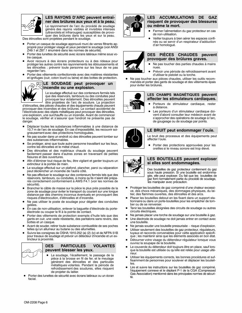
6-3. Blowing Out Inside Of Unit
� Do not remove case whenblowing out inside of unit.
To blow out unit, direct airflowthrough front and back louvers asshown.
ST-801 192
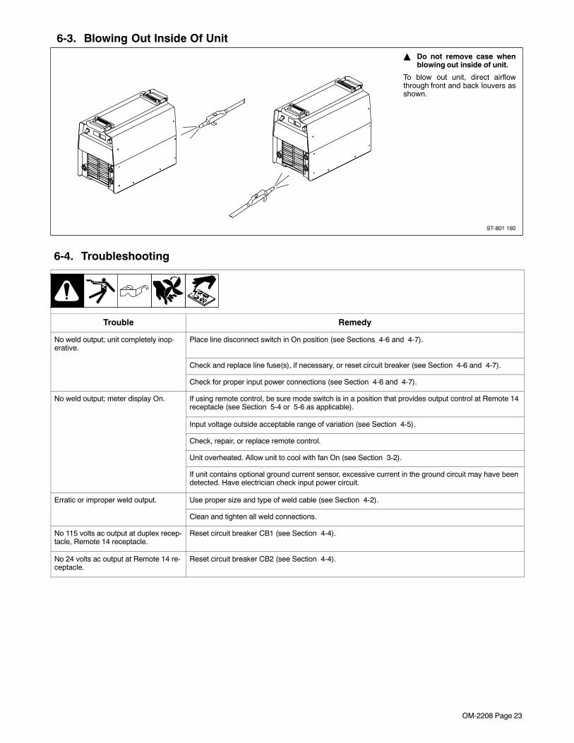
6-4. Troubleshooting
Trouble Remedy
No weld output; unit completely inop-erative.
Place line disconnect switch in On position (see Sections 4-6 and 4-7).
Check and replace line fuse(s), if necessary, or reset circuit breaker (see Section 4-6 and 4-7).
Check for proper input power connections (see Section 4-6 and 4-7).
No weld output; meter display On. If using remote control, be sure mode switch is in a position that provides output control at Remote 14receptacle (see Section 5-4 or 5-6 as applicable).
Input voltage outside acceptable range of variation (see Section 4-5).
Check, repair, or replace remote control.
Unit overheated. Allow unit to cool with fan On (see Section 3-2).
If unit contains optional ground current sensor, excessive current in the ground circuit may have beendetected. Have electrician check input power circuit.
Erratic or improper weld output. Use proper size and type of weld cable (see Section 4-2).
Clean and tighten all weld connections.
No 115 volts ac output at duplex recep-tacle, Remote 14 receptacle.
Reset circuit breaker CB1 (see Section 4-4).
No 24 volts ac output at Remote 14 re-ceptacle.
Reset circuit breaker CB2 (see Section 4-4).

OM-2208 Page 24
SECTION 7 − ELECTRICAL DIAGRAMS
197 550-B
Figure 7-1. Circuit Diagram For 230/460 Volt Models

OM-2208 Page 25
197 553-B
Figure 7-2. Circuit Diagram For 460/575 Volt Models

OM−2208 Page 26
SECTION 8 − PARTS LIST
801 428-H
� Hardware is common andnot available unless listed.
1
2
3
30
31 3233
34
129
3839
40
4249
5051
5253
5657
5859
60
61
22
62
6364
6
6512
11
7
8
9
1013
141516
17
1819
20
21
22
23
24
25
26
27
28
35
36
37
41
43
441145
46
47
48
54
55
66
67
45
Figure 8-1. Parts Assembly

OM-2208 Page 27
DescriptionPartNo.
Dia.Mkgs.
ItemNo.
Figure 8-1. Parts Assembly
Quantity
1 +175 148 WRAPPER 1. . . . . . . . . . . . . . . . . . . . . . . . . . . . . . . . . . . . . . . . . . . . . . . . . . . . . . . . . . . . . . . . . . . . . . 178 551 INSULATOR, side LH 1. . . . . . . . . . . . . . . . . . . . . . . . . . . . . . . . . . . . . . . . . . . . . . . . . . . . . . . . . . . . . . . . . 175 256 INSULATOR, side RH 1. . . . . . . . . . . . . . . . . . . . . . . . . . . . . . . . . . . . . . . . . . . . . . . . . . . . . . . . . . . . . . . . .
2 195 585 HANDLE 2. . . . . . . . . . . . . . . . . . . . . . . . . . . . . . . . . . . . . . . . . . . . . . . . . . . . . . . . . . . . . . . . . . . . . . . . . . 3 138 442 LABEL, caution falling equipment 2. . . . . . . . . . . . . . . . . . . . . . . . . . . . . . . . . . . . . . . . . . . . . . . . . . . . 4 HD1 182 918 TRANSDUCER, current 400A 1. . . . . . . . . . . . . . . . . . . . . . . . . . . . . . . . . . . . . . . . . . . . . . . . . . 5 203 342 BUS BAR, current sensor 1. . . . . . . . . . . . . . . . . . . . . . . . . . . . . . . . . . . . . . . . . . . . . . . . . . . . . . . . . . . 6 203 341 BUS BAR, output rectifier 1. . . . . . . . . . . . . . . . . . . . . . . . . . . . . . . . . . . . . . . . . . . . . . . . . . . . . . . . . . . 7 181 853 INSULATOR, screw 1. . . . . . . . . . . . . . . . . . . . . . . . . . . . . . . . . . . . . . . . . . . . . . . . . . . . . . . . . . . . . . . . 8 D1,2 201 531 KIT, diode power module 2. . . . . . . . . . . . . . . . . . . . . . . . . . . . . . . . . . . . . . . . . . . . . . . . . . . . . . 9 179 276 BUSHING, snap-in nyl 1.000 ID x 1.375mtg hole 2. . . . . . . . . . . . . . . . . . . . . . . . . . . . . . . . . . . . . . .
10 C5,6 R1 175 194 RESISTOR/CAPACITOR 1. . . . . . . . . . . . . . . . . . . . . . . . . . . . . . . . . . . . . . . . . . . . . . . . . . 11 RT1,2 173 632 THERMISTOR, NTC 30K ohm 2. . . . . . . . . . . . . . . . . . . . . . . . . . . . . . . . . . . . . . . . . . . . . . . . 12 185 835 LABEL, warning exploding parts 2. . . . . . . . . . . . . . . . . . . . . . . . . . . . . . . . . . . . . . . . . . . . . . . . . . . . . 13 +183 551 WINDTUNNEL, LH 1. . . . . . . . . . . . . . . . . . . . . . . . . . . . . . . . . . . . . . . . . . . . . . . . . . . . . . . . . . . . . . . . 14 ♦604 176 RECEPTACLE, str dx grd 2P3W 15A 125V 1. . . . . . . . . . . . . . . . . . . . . . . . . . . . . . . . . . . . . . . . . . 15 182 445 NUT, 1.000NPT 1. . . . . . . . . . . . . . . . . . . . . . . . . . . . . . . . . . . . . . . . . . . . . . . . . . . . . . . . . . . . . . . . . . . . 16 CB1 089 807 CIRCUIT BREAKER, man reset 1P 2.5A 250VAC 1. . . . . . . . . . . . . . . . . . . . . . . . . . . . . . . . . 16 CB1 ♦083 432 CIRCUIT BREAKER, man reset 1P 10A 250VAC 1. . . . . . . . . . . . . . . . . . . . . . . . . . . . . . . 17 CB2 083 432 CIRCUIT BREAKER, man reset 1P 10A 250VAC 1. . . . . . . . . . . . . . . . . . . . . . . . . . . . . . . . . 18 206 460 PANEL, rear 1. . . . . . . . . . . . . . . . . . . . . . . . . . . . . . . . . . . . . . . . . . . . . . . . . . . . . . . . . . . . . . . . . . . . . . . 18 ♦175 147 PANEL, rear (w/aux power) 1. . . . . . . . . . . . . . . . . . . . . . . . . . . . . . . . . . . . . . . . . . . . . . . . . . . . . . . 19 215 980 BUSHING, strain relief .709/.984 id x1.375 mtg hole 1. . . . . . . . . . . . . . . . . . . . . . . . . . . . . . . . . . . .
215 982 CABLE, power 1. . . . . . . . . . . . . . . . . . . . . . . . . . . . . . . . . . . . . . . . . . . . . . . . . . . . . . . . . . . . . . . . . . . . . . . . 20 PLATE, ident rear (order by model and serial number) 1. . . . . . . . . . . . . . . . . . . . . . . . . . . . . . . . . . . . . . . . . . . 21 ♦217 297 COVER, receptacle weatherproof duplex rcpt 1. . . . . . . . . . . . . . . . . . . . . . . . . . . . . . . . . . . . . . . . 22 175 138 BOX, louver 2. . . . . . . . . . . . . . . . . . . . . . . . . . . . . . . . . . . . . . . . . . . . . . . . . . . . . . . . . . . . . . . . . . . . . . . 23 148 329 LABEL, caution incorrect voltage (230/460) 1. . . . . . . . . . . . . . . . . . . . . . . . . . . . . . . . . . . . . . . . . . . . 23 182 227 LABEL, caution incorrect voltage (460/575) 1. . . . . . . . . . . . . . . . . . . . . . . . . . . . . . . . . . . . . . . . . . . . 24 192 853 BRACKET, mtg contactor/capacitor/PC Board 1. . . . . . . . . . . . . . . . . . . . . . . . . . . . . . . . . . . . . . . . . 25 PC1 213 664 CIRCUIT CARD, control (230/460) 1. . . . . . . . . . . . . . . . . . . . . . . . . . . . . . . . . . . . . . . . . . . . . . 25 PC1 215 045 CIRCUIT CARD, control (460/575) 1. . . . . . . . . . . . . . . . . . . . . . . . . . . . . . . . . . . . . . . . . . . . . .
PLG2 131 056 CONNECTOR & SOCKETS (RC2) 1. . . . . . . . . . . . . . . . . . . . . . . . . . . . . . . . . . . . . . . . . . . . . . . PLG3 130 203 CONNECTOR & SOCKETS (RC3) 1. . . . . . . . . . . . . . . . . . . . . . . . . . . . . . . . . . . . . . . . . . . . . . PLG4 115 094 CONNECTOR & SOCKETS (RC4) 1. . . . . . . . . . . . . . . . . . . . . . . . . . . . . . . . . . . . . . . . . . . . . . . PLG5 115 091 CONNECTOR & SOCKETS (RC5) 1. . . . . . . . . . . . . . . . . . . . . . . . . . . . . . . . . . . . . . . . . . . . . . . PLG7 115 093 CONNECTOR & SOCKETS (RC7) 1. . . . . . . . . . . . . . . . . . . . . . . . . . . . . . . . . . . . . . . . . . . . . . .
26 RC10 166 679 CONNECTOR & SOCKETS 1. . . . . . . . . . . . . . . . . . . . . . . . . . . . . . . . . . . . . . . . . . . . . . . . . . 27 W1,2 211 493 CONTACTOR, def prp 40a 8p dual 24vac coil w/interl (230/460 only) 1. . . . . . . . . . . . . .
173 763 STAND-OFF, No. 10-32 x 1.418 (230/460 only) 8. . . . . . . . . . . . . . . . . . . . . . . . . . . . . . . . . . . . . . . . . . . 28 T2 201 684 TRANSFORMER, control (230/460) 1. . . . . . . . . . . . . . . . . . . . . . . . . . . . . . . . . . . . . . . . . . . . . . . 28 T2 ♦193 774 TRANSFORMER, control (230/460) 1. . . . . . . . . . . . . . . . . . . . . . . . . . . . . . . . . . . . . . . . . . . . .
♦183 549 BRACKET, mtg aux transformer 1. . . . . . . . . . . . . . . . . . . . . . . . . . . . . . . . . . . . . . . . . . . . . . . . . . . . . . 28 T2 204 256 TRANSFORMER, control (460/575) 1. . . . . . . . . . . . . . . . . . . . . . . . . . . . . . . . . . . . . . . . . . . . . . . 30 207 727 WINDTUNNEL, RH 1. . . . . . . . . . . . . . . . . . . . . . . . . . . . . . . . . . . . . . . . . . . . . . . . . . . . . . . . . . . . . . . . 31 153 403 BUSHING, snap-in nyl .750 ID x 1.000mtg 2. . . . . . . . . . . . . . . . . . . . . . . . . . . . . . . . . . . . . . . . . . . . 32 177 547 BUSHING, snap-in nyl 1.125mtg 1. . . . . . . . . . . . . . . . . . . . . . . . . . . . . . . . . . . . . . . . . . . . . . . . . . . . . 33 CT1 175 199 TRANSFORMER, current 1. . . . . . . . . . . . . . . . . . . . . . . . . . . . . . . . . . . . . . . . . . . . . . . . . . . . . . 34 025 248 STAND-OFF, insul 2. . . . . . . . . . . . . . . . . . . . . . . . . . . . . . . . . . . . . . . . . . . . . . . . . . . . . . . . . . . . . . . . . 35 C1 186 015 CAPACITOR, polyp film .34uf 1000VAC (230/460) 1. . . . . . . . . . . . . . . . . . . . . . . . . . . . . . . . . 35 C1 193 858 CAPACITOR, polyp film .27uf 1000VAC (460/575) 1. . . . . . . . . . . . . . . . . . . . . . . . . . . . . . . . .
+When ordering a component originally displaying a precautionary label, the label should also be ordered.♦Part of 043 302 115V Aux Power Option (230/460).To maintain the factory original performance of your equipment, use only Manufacturer’s SuggestedReplacement Parts. Model and serial number required when ordering parts from your local distributor.

OM−2208 Page 28
DescriptionPartNo.
Dia.Mkgs.
ItemNo.
Figure 8-1. Parts Assembly (Continued)
Quantity
36 C3,4 192 935 CAPACITOR, elctlt 2700uf 450VDC (230/460) 2. . . . . . . . . . . . . . . . . . . . . . . . . . . . . . . . . . . . 36 C3,4 206 756 KIT, capacitor elctlt replacement (Includes) 1. . . . . . . . . . . . . . . . . . . . . . . . . . . . . . . . . . . . . . .
193 738 CAPACITOR, elctlt 1800 UF 500 VDC 2. . . . . . . . . . . . . . . . . . . . . . . . . . . . . . . . . . . . . . . . . . . . . . . . . . . 217 040 NUT, nylon m12 thread capacitor mounting 2. . . . . . . . . . . . . . . . . . . . . . . . . . . . . . . . . . . . . . . . . . . . . . .
37 PC2 +209 579 CIRCUIT CARD, interconnect (230/460) 1. . . . . . . . . . . . . . . . . . . . . . . . . . . . . . . . . . . . . . . . 37 PC2 +208 783 CIRCUIT CARD, interconnect (460/575) 1. . . . . . . . . . . . . . . . . . . . . . . . . . . . . . . . . . . . . . . .
PLG13 131 204 CONNECTOR & SOCKETS (RC13) 1. . . . . . . . . . . . . . . . . . . . . . . . . . . . . . . . . . . . . . . . . . . . . . PLG14,21 115 093 CONNECTOR & SOCKETS (RC14) (RC21) 2. . . . . . . . . . . . . . . . . . . . . . . . . . . . . . . . . . .
126 026 LABEL, warning electric shock 1. . . . . . . . . . . . . . . . . . . . . . . . . . . . . . . . . . . . . . . . . . . . . . . . . . . . . . . . . . 38 175 140 BRACKET, DI/DT 1. . . . . . . . . . . . . . . . . . . . . . . . . . . . . . . . . . . . . . . . . . . . . . . . . . . . . . . . . . . . . . . . . . 39 175 482 COIL, DI/DT 2. . . . . . . . . . . . . . . . . . . . . . . . . . . . . . . . . . . . . . . . . . . . . . . . . . . . . . . . . . . . . . . . . . . . . . . 40 109 056 CORE 2. . . . . . . . . . . . . . . . . . . . . . . . . . . . . . . . . . . . . . . . . . . . . . . . . . . . . . . . . . . . . . . . . . . . . . . . . . . . 41 SR1 179 629 KIT DIODE, power module 1. . . . . . . . . . . . . . . . . . . . . . . . . . . . . . . . . . . . . . . . . . . . . . . . . . . . . 42 PM1,2 208 173 KIT, transistor IGBT module 1. . . . . . . . . . . . . . . . . . . . . . . . . . . . . . . . . . . . . . . . . . . . . . . . . . 43 Z1 173 570 STABILIZER 1. . . . . . . . . . . . . . . . . . . . . . . . . . . . . . . . . . . . . . . . . . . . . . . . . . . . . . . . . . . . . . . . . . . 44 L1 173 563 INDUCTOR, input 1. . . . . . . . . . . . . . . . . . . . . . . . . . . . . . . . . . . . . . . . . . . . . . . . . . . . . . . . . . . . . . . 45 207 725 HEAT SINK, power module 1. . . . . . . . . . . . . . . . . . . . . . . . . . . . . . . . . . . . . . . . . . . . . . . . . . . . . . . . . . 46 T1 173 811 TRANSFORMER, HF (230/460) 1. . . . . . . . . . . . . . . . . . . . . . . . . . . . . . . . . . . . . . . . . . . . . . . . . . 46 T1 180 952 TRANSFORMER, HF (460/575) 1. . . . . . . . . . . . . . . . . . . . . . . . . . . . . . . . . . . . . . . . . . . . . . . . . . 47 207 467 HEAT SINK, rect 1. . . . . . . . . . . . . . . . . . . . . . . . . . . . . . . . . . . . . . . . . . . . . . . . . . . . . . . . . . . . . . . . . . . 48 175 255 INSULATOR, rectifier 1. . . . . . . . . . . . . . . . . . . . . . . . . . . . . . . . . . . . . . . . . . . . . . . . . . . . . . . . . . . . . . .
110 386 RELAY, 24VAC (460/575 only) 1. . . . . . . . . . . . . . . . . . . . . . . . . . . . . . . . . . . . . . . . . . . . . . . . . . . . . . . . . . 49 173 693 FOOT, mtg unit 4. . . . . . . . . . . . . . . . . . . . . . . . . . . . . . . . . . . . . . . . . . . . . . . . . . . . . . . . . . . . . . . . . . . . 50 176 736 SCREW, mtg foot 4. . . . . . . . . . . . . . . . . . . . . . . . . . . . . . . . . . . . . . . . . . . . . . . . . . . . . . . . . . . . . . . . . . 51 175 132 BASE 1. . . . . . . . . . . . . . . . . . . . . . . . . . . . . . . . . . . . . . . . . . . . . . . . . . . . . . . . . . . . . . . . . . . . . . . . . . . . 52 PC3 222 914 CIRCUIT CARD, front panel display (CC model) 1. . . . . . . . . . . . . . . . . . . . . . . . . . . . . . . . . . 52 PC3 219 820 CIRCUIT CARD, front panel display (CC/CV model) 1. . . . . . . . . . . . . . . . . . . . . . . . . . . . . . .
PLG11 115 091 CONNECTOR & SOCKETS (RC2) 1. . . . . . . . . . . . . . . . . . . . . . . . . . . . . . . . . . . . . . . . . . . . . . . 53 FM 175 084 MOTOR, fan 24VDC 3000RPM 1. . . . . . . . . . . . . . . . . . . . . . . . . . . . . . . . . . . . . . . . . . . . . . . . . 54 RC1 185 730 RECEPTACLE, w/leads & plug 1. . . . . . . . . . . . . . . . . . . . . . . . . . . . . . . . . . . . . . . . . . . . . . . . . 55 178 548 TERMINAL, connector friction 2. . . . . . . . . . . . . . . . . . . . . . . . . . . . . . . . . . . . . . . . . . . . . . . . . . . . . . . 56 C7,8 222 488 CAPACITOR ASSY, 2. . . . . . . . . . . . . . . . . . . . . . . . . . . . . . . . . . . . . . . . . . . . . . . . . . . . . . . . . . . 57 185 732 PANEL, front 1. . . . . . . . . . . . . . . . . . . . . . . . . . . . . . . . . . . . . . . . . . . . . . . . . . . . . . . . . . . . . . . . . . . . . . 58 129 525 RECEPTACLE, twlk insul fem 2. . . . . . . . . . . . . . . . . . . . . . . . . . . . . . . . . . . . . . . . . . . . . . . . . . . . . . . 58 ♦209 219 RECEPTACLE, twlk insul fem (Tweco) 2. . . . . . . . . . . . . . . . . . . . . . . . . . . . . . . . . . . . . . . . . . . . . . 59 NAMEPLATE, (order by model and serial number) 1. . . . . . . . . . . . . . . . . . . . . . . . . . . . . . . . . . . . . . . . . . . . . . 60 174 992 KNOB, pointer .840 2. . . . . . . . . . . . . . . . . . . . . . . . . . . . . . . . . . . . . . . . . . . . . . . . . . . . . . . . . . . . . . . . 61 175 855 DOOR, front 1. . . . . . . . . . . . . . . . . . . . . . . . . . . . . . . . . . . . . . . . . . . . . . . . . . . . . . . . . . . . . . . . . . . . . . 62 174 991 KNOB, pointer 1.250 2. . . . . . . . . . . . . . . . . . . . . . . . . . . . . . . . . . . . . . . . . . . . . . . . . . . . . . . . . . . . . . . 63 176 226 INSULATOR, switch power 1. . . . . . . . . . . . . . . . . . . . . . . . . . . . . . . . . . . . . . . . . . . . . . . . . . . . . . . . . . 64 S1 128 756 SWITCH, tgl 3PST 40A 600VAC 1. . . . . . . . . . . . . . . . . . . . . . . . . . . . . . . . . . . . . . . . . . . . . . . . . 65 134 327 LABEL, warning general precautionary 2. . . . . . . . . . . . . . . . . . . . . . . . . . . . . . . . . . . . . . . . . . . . . . . . 66 199 840 BUS BAR, diode 2. . . . . . . . . . . . . . . . . . . . . . . . . . . . . . . . . . . . . . . . . . . . . . . . . . . . . . . . . . . . . . . . . . 67 190 125 LABEL, warning electric shock power cord 1. . . . . . . . . . . . . . . . . . . . . . . . . . . . . . . . . . . . . . . . . . . .
+When ordering a component originally displaying a precautionary label, the label should also be ordered.♦Part of 195 181 Tweco Connector OptionTo maintain the factory original performance of your equipment, use only Manufacturer’s SuggestedReplacement Parts. Model and serial number required when ordering parts from your local distributor.

OM-2208 Page 29
Notes

OM−2208 Page 30
Notes

Warranty Questions?
Call1-800-4-A-MILLERfor your localMiller distributor.
miller_warr 1/05
Your distributor also givesyou ...
ServiceYou always get the fast,reliable response youneed. Most replacementparts can be in yourhands in 24 hours.
SupportNeed fast answers to thetough welding questions?Contact your distributor.The expertise of thedistributor and Miller isthere to help you, everystep of the way.
Effective January 1, 2005(Equipment with a serial number preface of “LF” or newer)This limited warranty supersedes all previous Miller warranties and is exclusive with no other
guarantees or warranties expressed or implied.
LIMITED WARRANTY − Subject to the terms and conditionsbelow, Miller Electric Mfg. Co., Appleton, Wisconsin, warrants toits original retail purchaser that new Miller equipment sold afterthe effective date of this limited warranty is free of defects inmaterial and workmanship at the time it is shipped by Miller.THIS WARRANTY IS EXPRESSLY IN LIEU OF ALL OTHERWARRANTIES, EXPRESS OR IMPLIED, INCLUDING THEWARRANTIES OF MERCHANTABILITY AND FITNESS.
Within the warranty periods listed below, Miller will repair orreplace any warranted parts or components that fail due to suchdefects in material or workmanship. Miller must be notified inwriting within thirty (30) days of such defect or failure, at whichtime Miller will provide instructions on the warranty claimprocedures to be followed.
Miller shall honor warranty claims on warranted equipmentlisted below in the event of such a failure within the warrantytime periods. All warranty time periods start on the date that theequipment was delivered to the original retail purchaser, or oneyear after the equipment is sent to a North American distributoror eighteen months after the equipment is sent to anInternational distributor.
1. 5 Years Parts — 3 Years Labor
* Original main power rectifiers* Inverters (input and output rectifiers only)
2. 3 Years — Parts and Labor
* Transformer/Rectifier Power Sources* Plasma Arc Cutting Power Sources* Semi-Automatic and Automatic Wire Feeders* Inverter Power Sources (Unless Otherwise Stated)* Water Coolant Systems (Integrated)* Intellitig* Maxstar 150* Engine Driven Welding Generators
(NOTE: Engines are warranted separately bythe engine manufacturer.)
3. 1 Year — Parts and Labor Unless Specified
* DS-2 Wire Feeder* Motor Driven Guns (w/exception of Spoolmate
Spoolguns)* Process Controllers* Positioners and Controllers* Automatic Motion Devices* RFCS Foot Controls* Induction Heating Power Sources and Coolers* Water Coolant Systems (Non-Integrated)* Flowgauge and Flowmeter Regulators (No Labor)* HF Units* Grids* Maxstar 85, 140* Spot Welders* Load Banks* Arc Stud Power Sources & Arc Stud Guns* Racks* Running Gear/Trailers* Plasma Cutting Torches (except APT & SAF
Models)* Field Options
(NOTE: Field options are covered under TrueBlue® for the remaining warranty period of theproduct they are installed in, or for a minimum ofone year — whichever is greater.)
4. 6 Months — Batteries
5. 90 Days — Parts
* MIG Guns/TIG Torches
* Induction Heating Coils and Blankets
* APT & SAF Model Plasma Cutting Torches
* Remote Controls
* Accessory Kits
* Replacement Parts (No labor)
* Spoolmate Spoolguns
* Canvas Covers
Miller’s True Blue® Limited Warranty shall not apply to:
1. Consumable components; such as contact tips,cutting nozzles, contactors, brushes, slip rings,relays or parts that fail due to normal wear. (Exception:brushes, slip rings, and relays are covered on Bobcat,Trailblazer, and Legend models.)
2. Items furnished by Miller, but manufactured by others,such as engines or trade accessories. These items arecovered by the manufacturer’s warranty, if any.
3. Equipment that has been modified by any party other thanMiller, or equipment that has been improperly installed,improperly operated or misused based upon industrystandards, or equipment which has not had reasonableand necessary maintenance, or equipment which hasbeen used for operation outside of the specifications for theequipment.
MILLER PRODUCTS ARE INTENDED FOR PURCHASE ANDUSE BY COMMERCIAL/INDUSTRIAL USERS ANDPERSONS TRAINED AND EXPERIENCED IN THE USE ANDMAINTENANCE OF WELDING EQUIPMENT.
In the event of a warranty claim covered by this warranty, theexclusive remedies shall be, at Miller’s option: (1) repair; or (2)replacement; or, where authorized in writing by Miller inappropriate cases, (3) the reasonable cost of repair orreplacement at an authorized Miller service station; or (4)payment of or credit for the purchase price (less reasonabledepreciation based upon actual use) upon return of the goods atcustomer’s risk and expense. Miller’s option of repair orreplacement will be F.O.B., Factory at Appleton, Wisconsin, orF.O.B. at a Miller authorized service facility as determined byMiller. Therefore no compensation or reimbursement fortransportation costs of any kind will be allowed.
TO THE EXTENT PERMITTED BY LAW, THE REMEDIESPROVIDED HEREIN ARE THE SOLE AND EXCLUSIVEREMEDIES. IN NO EVENT SHALL MILLER BE LIABLE FORDIRECT, INDIRECT, SPECIAL, INCIDENTAL ORCONSEQUENTIAL DAMAGES (INCLUDING LOSS OFPROFIT), WHETHER BASED ON CONTRACT, TORT ORANY OTHER LEGAL THEORY.
ANY EXPRESS WARRANTY NOT PROVIDED HEREIN ANDANY IMPLIED WARRANTY, GUARANTY ORREPRESENTATION AS TO PERFORMANCE, AND ANYREMEDY FOR BREACH OF CONTRACT TORT OR ANYOTHER LEGAL THEORY WHICH, BUT FOR THISPROVISION, MIGHT ARISE BY IMPLICATION, OPERATIONOF LAW, CUSTOM OF TRADE OR COURSE OF DEALING,INCLUDING ANY IMPLIED WARRANTY OFMERCHANTABILITY OR FITNESS FOR PARTICULARPURPOSE, WITH RESPECT TO ANY AND ALL EQUIPMENTFURNISHED BY MILLER IS EXCLUDED AND DISCLAIMEDBY MILLER.
Some states in the U.S.A. do not allow limitations of how long animplied warranty lasts, or the exclusion of incidental, indirect,special or consequential damages, so the above limitation orexclusion may not apply to you. This warranty provides specificlegal rights, and other rights may be available, but may varyfrom state to state.
In Canada, legislation in some provinces provides for certainadditional warranties or remedies other than as stated herein,and to the extent that they may not be waived, the limitationsand exclusions set out above may not apply. This LimitedWarranty provides specific legal rights, and other rights may beavailable, but may vary from province to province.

PRINTED IN USA © 2005 Miller Electric Mfg. Co. 1/05
Miller Electric Mfg. Co.An Illinois Tool Works Company1635 West Spencer StreetAppleton, WI 54914 USA
International Headquarters−USAUSA Phone: 920-735-4505 Auto-AttendedUSA & Canada FAX: 920-735-4134International FAX: 920-735-4125
European Headquarters −United KingdomPhone: 44 (0) 1204-593493FAX: 44 (0) 1204-598066
www.MillerWelds.com
Model Name Serial/Style Number
Purchase Date (Date which equipment was delivered to original customer.)
Distributor
Address
City
State Zip
Please complete and retain with your personal records.
Always provide Model Name and Serial/Style Number.
Contact a DISTRIBUTOR or SERVICE AGENCY near you.
Welding Supplies and Consumables
Options and Accessories
Personal Safety Equipment
Service and Repair
Replacement Parts
Training (Schools, Videos, Books)
Technical Manuals (Servicing Informationand Parts)
Circuit Diagrams
Welding Process Handbooks
Contact the Delivering Carrier to:
For Service
Owner’s Record
File a claim for loss or damage duringshipment.
For assistance in filing or settling claims, contactyour distributor and/or equipment manufacturer’sTransportation Department.
Contact your Distributor for:
To locate a Distributor or Service Agency visitwww.millerwelds.com or call 1-800-4-A-Miller
Related Documents