NZMAA Flying Rules: Section 3: Control Line May 2017 Page 1 of 37 NZMAA Flying Rules: Section 3: Control Line Updates and Alterations Date Paragraph Change Feb 2006 2.3.2 Renumbered 2.3.3 Renumbered 2.3.4 Renumbered Feb 2008 3.1b) 3.4 Amended Amended 3.6 Amended 3.7.b) Amended 3.8.b) Amended 3.10.1 Amended 3.10.3 Amended 3.10.4 4.1.b) Amended Added Mar 2009 1.2.1 Add elec power section 3.6 Change to the helpers 3.10.1 Change to the starting Feb 2010 5.11.2.h) Amended 7.2.h) Added July 2015 5.11.5.f) Appendix C Added Amended May 2017 General format amendments H1 to H4 Heading styles added, numbered list levels applied to all sections, auto table of contents, cross references, header & footer corrected. D.Thornley with help from Don Robinson January 2018 2017 Remits for F2f, Classic FAI, Use of third model in slow combat final all included. D. Thornley

Welcome message from author
This document is posted to help you gain knowledge. Please leave a comment to let me know what you think about it! Share it to your friends and learn new things together.
Transcript

NZMAA Flying Rules: Section 3: Control Line
May 2017 Page 1 of 37
NZMAA Flying Rules: Section 3: Control Line
Updates and Alterations
Date
Paragraph
Change
Feb 2006 2.3.2 Renumbered
2.3.3 Renumbered
2.3.4 Renumbered
Feb 2008 3.1b) 3.4
Amended Amended
3.6 Amended
3.7.b) Amended
3.8.b) Amended
3.10.1 Amended
3.10.3 Amended
3.10.4 4.1.b)
Amended Added
Mar 2009 1.2.1 Add elec power section
3.6 Change to the helpers
3.10.1 Change to the starting
Feb 2010 5.11.2.h) Amended
7.2.h) Added
July 2015
5.11.5.f) Appendix C
Added Amended
May 2017 General format amendments H1 to H4 Heading styles added, numbered list levels applied to all sections, auto table of contents, cross references, header & footer corrected.
D.Thornley with help from Don Robinson
January 2018 2017 Remits for F2f, Classic FAI, Use of third model in slow combat final all included.
D. Thornley
NZMAA Flying Rules: Section 3: Control Line
May 2017 Page 2 of 37
Table of Contents 1. CONTROL LINE: GENERAL RULES ............................................................................................. 4
1.1 GENERAL ..................................................................................................................................... 4
1.2 MOTIVE POWER .......................................................................................................................... 4
1.3 CONTROL LINES ......................................................................................................................... 4
1.4 NUMBER OF MODELS................................................................................................................ 4
1.5 MOTORS....................................................................................................................................... 5
1.6 CONSTRUCTION OF MODELS .................................................................................................. 5
1.7 ENTRANT ..................................................................................................................................... 5
2. CONTROL LINE SPEED ................................................................................................................. 6
2.1 DEFINITION .................................................................................................................................. 6
2.2 GENERAL ...................................................................................................................................... 6
2.3 SPECIFICATIONS ........................................................................................................................ 6
2.4 PERCENTAGE SPEED ................................................................................................................ 7
2.5 SAFETY ........................................................................................................................................ 7
2.6 FLYING RULES ............................................................................................................................ 7
3. CONTROL LINE SPORTSMAN AEROBATICS ............................................................................ 9
3.1 DEFINITIONS ............................................................................................................................... 9
3.2 GENERAL ..................................................................................................................................... 9
3.3 SPECIFICATIONS ........................................................................................................................ 9
3.4 LINE TEST .................................................................................................................................... 9
3.5 OFFICIAL FLIGHTS ..................................................................................................................... 9
3.6 HELPERS ..................................................................................................................................... 9
3.7 EXECUTION OF MANOEUVRES ................................................................................................. 9
3.8 JUDGING .................................................................................................................................... 10
3.9 MOTOR STOPPING ................................................................................................................... 10
3.10 MANOEUVRES .......................................................................................................................... 10
4. CLASSIC STUNT ............................................................................................................................ 15
4.1 Rules and schedule ..................................................................................................................... 15
5. CONTROL LINE TEAM RACING GENERAL RULES ..................................................................... 16
5.1 DEFINITION ................................................................................................................................. 16
5.2 NEW ZEALAND TEAM RACING CLASSES ............................................................................. 16
5.3 THE COURSE.............................................................................................................................. 16
5.4 GENERAL SPECIFICATIONS ................................................................................................ 17
5.5 ORGANISATION OF THE RACES............................................................................................... 17
5.6 RACE FROM START TO FINISH ................................................................................................ 18
5.7 DEFINITION OF AN OFFICIAL FLIGHT ....................................................................................... 19
5.8 WARNINGS: ELIMINATIONS ...................................................................................................... 19

NZMAA Flying Rules: Section 3: Control Line
May 2017 Page 3 of 37
5.9 RECORDS AND DECENTRALISED CONTESTS ....................................................................... 20
5.10 CONTROL LINE TEAM RACE - CLASS 1/2A RULES ................................................................. 21
5.11 CONTROL LINE TEAM RACE - GOODYEAR RULES ................................................................. 21
5.12 CONTROL LINE TEAM RACE - CLASS B RULES ...................................................................... 22
6. CONTROL LINE COMBAT GENERAL RULES ............................................................................... 26
6.1 DEFINITIONS ............................................................................................................................. 26
6.2 NUMBER OF MODELS ................................................................................................................ 26
6.3 PULL TEST .................................................................................................................................. 26
6.4 STREAMERS ............................................................................................................................... 26
6.5 DRAWING OF OPPONENTS AND STARTING ........................................................................... 26
6.6 TERMINATION OF THE CONTEST ............................................................................................. 27
6.7 CIRCLE MARKING ...................................................................................................................... 27
6.8 PITTING OF MODEL ................................................................................................................... 27
6.9 SCORING .................................................................................................................................... 27
6.10 GENERAL .................................................................................................................................... 28
6.11 OFFENCES .................................................................................................................................. 28
7. CONTROL LINE SLOW COMBAT RULES ...................................................................................... 28
7.1 GENERAL ................................................................................................................................... 28
7.2 SPECIFICATIONS ....................................................................................................................... 29
8. UNOFFICIAL CONTROL LINE EVENTS ........................................................................................ 29
8.1 CLASSIC TEAM RACING ............................................................................................................ 29
8.2 MIDGE SPEED ........................................................................................................................... 30
8.3 PHANTOM RACING .................................................................................................................. 31
9. APPENDIX A .................................................................................................................................. 32
10. APPENDIX B .................................................................................................................................. 34
11. APPENDIX C ................................................................................................................................ 37
NZMAA Flying Rules: Section 3: Control Line
May 2017 Page 4 of 37
1. CONTROL LINE: GENERAL RULES
1.1 GENERAL
Control line classes flown in New Zealand include the FAI International classes of F2A (Speed), F2B (Aerobatics), F2C and F2F (Team Race) and F2D (Combat). As regulations for the FAI classes differ from domestic New Zealand classes, the FAI events are flown to the rules in the current FAI Sporting Code.
1.2 MOTIVE POWER
Control Line model aircraft are powered by a motor(s) in which the energy is obtained by the combustion or expansion of a fluid or gas acting on a piston or pistons, except for Class 5 (Jet) Speed.
1.2.1 ELECTRIC POWER
a) Electric power is permitted for Sportsman Aerobatics and Classic Stunt.
b) Electric power shall be limited to a maximum no-load voltage of 42 volts.
c) Mufflers are not required
d) Provided they are used only to end a flight, the use of engine/s shut-off systems, either operated by the pilot or functioning fully automatically, shall be permitted.
1.3 CONTROL LINES
All lines which control the flight of the model must be of steel, free of corrosion, kinks or weaknesses. No cord or string connections may be used as part of the control lines or in their attachment to the control handle.
1.3.1 LOAD TESTS
The specified load tests should be applied by slowly increasing the pull so no shock load is applied and the maximum load should be kept for three seconds.
1.3.2 LINE LENGTH
Line length is measured from the axis of the control handle to the axis of the propeller for a single motor model and to the axis of symmetry for a multi-motor model.
1.3.3 LINE DIAMETER
Unless otherwise specified, the minimum line diameters required are allowed a tolerance of 0.011 mm. Line diameters are to be tested by micrometer at random points in at least three places along the line.
1.3.4 LINE GROUPING
No intentional twisting and/or linking of the two lines together shall be permitted between the point of exit from the model and a point 300 mm from the axis of the handle.
1.4 NUMBER OF MODELS
Unless otherwise specified, a competitor is allowed a maximum of two models per class. The competitor may interchange and repair their various parts as desired, providing the resulting complete model complies with the specifications.
NZMAA Flying Rules: Section 3: Control Line
May 2017 Page 5 of 37
1.5 MOTORS
A given motor may not be used by more than one competitor in a particular class.
1.6 CONSTRUCTION OF MODELS
a) For all control line classes, a particular model may only be flown by one competitor in a given contest.
b) For International control line contests flown to the FAI rules or for trials to select competitors for such contests, the FAI rules pertaining to the builder of the model shall apply.
1.7 ENTRANT
An entrant may be either a Solo or, for New Zealand Control Line Speed and Team Race Classes only, a Team.

NZMAA Flying Rules: Section 3: Control Line
May 2017 Page 6 of 37
2. CONTROL LINE SPEED
2.1 DEFINITION
Control Line Speed is a contest in which the object of the model is to obtain a maximum speed sustained under its own power over a measured course.
2.2 GENERAL
a) All general rules apply. (General Competition Rules and C/L rules chapter 1.)
b) For New Zealand Speed classes the “Entrant” shall comprise one pilot and one or two mechanics.
2.3 SPECIFICATIONS
Class Motor Size
(cc)
Min.Line Length
(m)
Min. two line Dia.
(mm)
Min. Mono line Dia.
(mm)
Max Wgt. (g)
Distance Timed (1 km)
1 0-2.2 open
exhaust 15.92 0.30 solid
500 10 laps
or
or
0-1.5 with exhaust system
0.35
stranded
2 2.51-3.5 15.92 0.4 0.6 800 10 laps
3 3.51-5.0 17.69 0.45 0.6 1000 9 laps
4 5.01-10.0 19.90 0.5 0.8 1400 8 laps
5 Jet 19.90 0.5 0.8 1400 8 laps
2.3.1 Fuel Restrictions
a) Class 1(open exhaust),2,3,4,5 Unrestricted.
b) Class 1, with exhaust system. 5% Nitro max.
2.3.2 Load Test
A load test of forty times the weight of the model shall be applied to the assembled control handle, lines and model. The same load shall be applied separately to the safety strap when attached to the competitor's wrist.
2.3.3 Tolerances
Line Diameter: Minimum line diameters are permitted a tolerance of minus 0.011 mm.
2.3.4 Alternative Line Length
A competitor may elect to fly using a line length greater than the minimum specified in rule 2.3 In this case the model will be timed for the minimum number of laps required to cover the course distance (1 km).

NZMAA Flying Rules: Section 3: Control Line
May 2017 Page 7 of 37
Line Length Number of Laps
Minimum 15.92m 10
Minimum 17.69m 9
Minimum 19.90 8
2.3.5 Maximum line length.
Maximum line length is 21.5m
2.4 PERCENTAGE SPEED
2.4.1 Overview
Percentage speed is a method of having a meaningful control line speed contest when there are only few competitors spread over several different speed classes. This is achieved by comparing the speed in each class to the New Zealand record.
Percentage speed will normally be flown for the all the New Zealand speed classes, 1, 2, 3, 4 and 5. Other combinations of speed classes may be used if advised before the contest.
2.4.2 Classification
a) The best speed by each competitor in each class is compared to the current NZ record for that class, and calculated as a percentage of that record, to the nearest two decimal places.
b) Placing are determined by these percentages.
c) Open/Junior, Open and Junior categories may be flown separately, in which case the speeds will compared against the Open or Junior record as appropriate for that class. When Open and Junior categories are flown combined then speeds shall be compared only against the Open record for that class.
d) Multiple entries. A competitor may make multiple entries by flying in more than one speed class. In this case only the best percentage result is used for classification. All other results are discarded.
e) Records. For the purposes of the contest the records that will be used are those that are published on the NZMAA website on the day of the contest. If there are any new records that have not yet been ratified or published these are not considered.
2.5 SAFETY
a) Where a protecting wire screen is not available offering complete protection to the spectators, such persons shall be at least 22 m from the perimeter of the flying circle.
b) Any competitor releasing the controls either purposely or accidentally shall be barred from further participation in that class. All handles must be fitted with a safety strap which shall be attached to the competitor's wrist during the flight.
c) After a crash, the model shall be inspected for damage before being allowed to fly again.
2.6 FLYING RULES
a) Pylon: A fixed pivot, post or pylon shall be used during the flights and the competitor shall keep their hand holding the control handle or the control handle itself, in or against the fork at the top of the pylon during the entire timed portion of the flight.

NZMAA Flying Rules: Section 3: Control Line
May 2017 Page 8 of 37
b) Definition of an Attempt: It will be considered an attempt when the competitor does not engage the control handle in or against the pylon fork within three minutes after the starting signal.
c) Number of Attempts: In the case of an unsuccessful first attempt for an official flight, the competitor is entitled to a second attempt.
d) The flight is official once the timekeepers have started their stopwatches in accordance with rule 2.6 g)
e) Number of Flights: Each competitor is entitled to three official flights.
f) Number of Helpers: The competitor is allowed two helpers. The competitor or his helpers may either pilot the model or carry out the functions of starting and adjusting the motor(s). For a junior contest or a junior record, the pilot must be a junior.
g) Starting of Timing: The timing commences officially, when the competitor has placed their handle in or against the pylon fork and the model having made two complete circuits, again passes the height marker on the edge of the circuit directly opposite the time-keepers.
h) Cancellation of the Flight: A flight is cancelled when:
a) Any physical effort for the purpose of increasing the speed of the model during an official flight is applied by the competitor.
b) If at any time during the speed course, the model exceeds a height of six metres or sustains a height in excess of three metres or less than one metre for more than one lap.
c) Continuous contact is not maintained with the pylon fork during the official flight.
d) Jettisoning occurs during the official flight.
i) Number of Time-keepers and Judges:
a) The time must be taken by at least two time-keepers.
b) Speed judges at least two in number shall be responsible for observing the conduct of the competitor, and the altitude of the flight.
c) The time recorded is the mean of the times indicated on the watches.
d) In the case when the difference between any two times recorded is greater than 2/10th of a second, the competitor has the right to repeat the flight.
j) Classification:
The best speed attained during the three flights is the only one taken into account for classification, and is subject to rechecking the declared characteristics of the models which achieve the first three positions.
The speed is taken to the nearest lower 1/10 kilometre per hour using watches of 1/100 second measurement.
To separate the competitors in the case of a tie, the average of the competitor's two best flights will be taken.
In the case of the two best flights producing a tie, the result of the third official flights will be taken to determine the winner.

NZMAA Flying Rules: Section 3: Control Line
May 2017 Page 9 of 37
3. CONTROL LINE SPORTSMAN AEROBATICS
3.1 DEFINITIONS
a) Control Line Sportsman Aerobatics is a contest in which the object of the model is to perform the prescribed manoeuvres.
b) A Sportsman is defined as any person who has not scored more than 850 points (average score per judge) in a round of FAI F2B Aerobatics at any National Contest for three previous years.
3.2 GENERAL
All general rules apply. (General Competition Rules and C/L rules chapter 1.)
3.3 SPECIFICATIONS
a) Maximum line length: 21.5 m
b) Minimum line diameter: 0.3 mm (with a tolerance of minus 0.011 mm)
c) Single line control not permitted.
d) Motors over 3.5 cc must be fitted with an effective silencer.
e) Models need not be fitted with an undercarriage but hand launched models will receive lower take-off and landing coefficients than those that ROG.
3.4 LINE TEST
A test load of 10 times the total weight of the model aircraft without fuel shall be evenly and smoothly applied to the assembled control handle, lines and model aircraft.
3.5 OFFICIAL FLIGHTS
3.5.1 Each competitor is entitled to three official flights. The total of the two highest scoring flights will determine placings.
3.5.2 There is an official flight when the model becomes airborne.
3.5.3 No-Flights: The competitor is entitled to one no-flight for each official flight. There shall be a no-flight if:
a) The model does not become airborne within three minutes of the starting signal:
or
b) The competitor does not enter the circle within two minutes from being called to fly.
In the event of a no-flight, the competitor may make their repeat attempt immediately or must make their repeat attempt immediately after three other competitor's official flights.
3.5.4 The flight is cancelled when jettisoning occurs.
3.6 HELPERS
Each competitor is entitled to two helpers. The competitor or helpers may start and adjust the motor(s). The competitor may have a caller present in the circle centre.
3.7 EXECUTION OF MANOEUVRES
a) The manoeuvres must be executed in the order listed. The competitor may attempt a manoeuvre only once in any one flight and must advise the judges prior to each flight the

NZMAA Flying Rules: Section 3: Control Line
May 2017 Page 10 of 37
manoeuvres that will not be attempted.
b) Between the end of one manoeuvre and the start of the next, the competitor must fly a minimum of 1½ laps. The level of portion of the intervening laps shall be flown at a height of between 1 and 3 metres.
c) The competitor must complete the flight programme within 7 minutes including the take-off and the landing (to the instant the model comes to a stop). Any manoeuvres not completed at the end of the 7 minute period will not be judged. This 7 minute time limit commences when a competitor gives a hand signal prior to starting the motor(s), but no later than 3 minutes from the moment the competitor has entered the circle.
3.8 JUDGING
a) One or two judges shall be appointed and remain unchanged for the duration of the contest.
b) Judging shall take place from outside the circle.
c) Judges are responsible for observing each attempt at an official flight and award a score of 0 to 10 points for each manoeuvre as it is executed. The judge's marks, multiplied by the assigned coefficients (k factors) are totaled and the totals averaged to determine a competitor's score.
d) A master time-keeper shall give visual indication to the competitor and judges of elapsed time from the moment the competitor gives a hand signal prior to starting the motor(s), at one minute, three minutes and seven minutes stages.
3.9 MOTOR STOPPING
In the event of the motor(s) stopping before the completion of a multiple manoeuvre, the competitor, if and when the model is airborne again, shall fly the complete manoeuvre but will only be judged on those portions not previously judged.
3.10 MANOEUVRES
Manoeuvre 3.10.1, 3.10.2 and 3.10.6 to 3.10.12 inclusive are identical to those described for FAI F2B Aerobatics. For full descriptions of these manoeuvres, refer to the FAI Sporting Code for F2B Aerobatics.
The Climb, Dive and Wingover are not in the F2B schedule and are described below.
3.10.1 Starting: k=1:
All Judges shall award a mark 10 (ten) if the model aircraft begins its ground roll for the take-off manoeuvre within 1 minute of giving the ready to start hand signal.
Both manual and motor starting devices such as electric starters shall be permitted and the 10 points shall be awarded if the above 1 minute condition is fulfilled, whatever the method of motor starting used.
But a mark 0 (zero) shall be given if:
a) No hand signal is given or,
b) The competitor starts his motor/s before his hand signal has been acknowledged or,
c) The take-off ground roll begins more than 1 minute after his hand signal was acknowledged.
3.10.2 Take-off: k=2: for ROG, k=1: for Hand Launch
A correct take-off consists of the model rolling smoothly along the ground for distance of not less than 4,5 metres, but not greater than one quarter of a lap. The model then rises smoothly into the air with a gradual climb and a smooth level-off to normal flight level

NZMAA Flying Rules: Section 3: Control Line
May 2017 Page 11 of 37
over the point at which the model commenced its ground roll. Model continues on for two smooth laps of normal level flight to point of original level-off.
Errors: Model bounces or becomes airborne too soon, or too late. Take-off climb or level-off are not gradual and smooth. Level-off occurs too soon, or too late. Level-off and normal flight level are not within a height of 1.20 m - 1.80 m.
3.10.3 Climb: k=2:
A correct climb starts from normal level flight makes a vertical climb for a minimum of 4 metres and recovers into level flight before descending to a height of between 1 and 3 metres. Errors: Model starts at other than normal level flight. Model wobbles when going into or out of climb. Climb is not vertical or is less than 4 metres.
3.10.4 Dive: k=2:
A correct dive manoeuvre starts with an entry from normal level flight. Use a ¾ of a lap to climb to a height of 45 line elevation and maintain this height for a minmum 1/8 of a lap. The model makes a vertical dive for a minimum of 4 metres and recovers to normal level flight. Errors: Model begins vertical dive at other than 45 degrees. Model wobbles when going into or out of dive; Dive is not vertical or is less than 4 metres.
3.10.5 Wingover: k=4:
A correct wingover starts from normal level flight, makes a vertical climb and dive, passing directly over the competitor's head, cutting the ground circle in half and recovers into normal level flight. Errors: Model starts at other than normal level flight. Model does not cross directly over competitor's head. Model does not cross circle in a straight line. Model does not recover at normal level flight.
3.10.6 Three inside loops: k=1: 1st loop k=2: 2nd loop k=3: 3rd loop
Correct loops are judged when the model starts from normal flight level and makes a series of three smooth round loops, all in the same place with the bottoms of the loops at normal flight level and the tops of the loops with the line(s) at 45 degrees elevation. The model then continues for another half loop, recovering inverted and descending to normal flight level, flying two laps before being judged for inverted flight. Errors: Loops are rough and irregular (i. e. egg-shaped, hexagonal, etc. Bottoms of loops are not at 1.20 - 1.80 m height. Tops of loops vary more than 0.60 m, plus or minus, of the 45 degrees elevation point. Second and third loops vary more than 0.60 m from the path of the first loop.
3.10.7 Inverted flight: k=2: (2 laps)
Correct inverted flight is judged when the model makes two smooth, stable laps at normal flight level. Errors: Height is not 1.20 m - 1.80 m. Height varies more than 0.60 m.
3.10.8 Three outside loops: k=1: 1st loop k=2: 2nd loop k=3: 3rd loop
Correct loops are judged when model starts from inverted position at normal flight level and makes a series of three smooth, round loops, all in the same place, with the bottoms of

NZMAA Flying Rules: Section 3: Control Line
May 2017 Page 12 of 37
the loops at normal flight level and the tops of the loops with the line(s) at 45 degrees elevation. The model then continues for another half loop, recovering at normal flight level. Errors: Loops are rough and irregular (i. e. egg-shaped, hexagonal, etc.). Bottoms are not at 1.20 m - 1.80 m height. Tops of loops vary more than 0.60 m, plus or minus of the 45 degree elevation point. Second and third loops vary more than 0.60 m from the path of the first loop.
3.10.9 Two horizontal eights: k=3: 1st eight, k=4: 2nd eight
Horizontal eights are to be entered and completed at the intersection point of the circles and exit at the same point. The inside loop must be flown first. Correct eights are judged when the model makes two eights, each consisting of two round circles or loops of the same size, tangent to each other, and in a horizontal line. The model must enter the eight from normal flight level and be vertical at the intersection point of tangency of the circles. The eights must be symmetrical. At the top of each circle the model must be at the 45 degrees elevation point; the bottoms of circles must be at normal flight level.
Errors: Model is not vertical at entry. Model at top of circles is not within 0.60 m of 45 degrees elevation point. Bottom of circles not within 1.20 m - 1.80 m height. Loops are not round and equal in size. Point of intersection varies. Second eight is not in the same position as the first.
3.10.10 Vertical eight: k=4: (One)
The vertical eight is to be started at the point of 45 degrees elevation and finished at the same point in inverted flight. The inside loop must be flown first. A correct eight is judged when the model makes two round circles or loops of the same size, tangent to each other, and in a vertical line. The model must be horizontal at the intersection point of tangency of the two circles. The eight must be symmetrical, the top of the heights at a point 90 degrees over flier’s head, and the bottom of the heights at normal flight level. Errors: Model is not horizontal at entry. Entry is not within 0.60 m of the 45 degrees elevation point. Tops of eight is not within 1.20 m from the 90 degrees point. Bottom of eight is not at a height between 1.20 m - 1.80 m. Loops are not round and equal in size. Point of intersection varies.
3.10.11 Overhead eight: k=4: (One)
The overhead eight are to be entered and completed at the intersection point of the circles, directly over the flier’s head, and exit from the same point. The inside loop must be flown first. A correct overhead eight is judged when the model makes two round circles of the same size, with the intersection or point of tangency directly over the flier’s head. The model must enter the eight with a vertical climb through the centre of the circle, and must point in this direction at the centre of the eight. The eight must be symmetrical and the model at the lowest point of each circle must be at a point of 45 degrees elevation. Errors: Model is not vertically overhead at entry. Low point of circles is not within 0.60 m of the 45 degrees elevation point. Loops are not round and equal in size. Point of intersection varies.
3.10.12 Landing: k=2: for model without undercarriage. k=5: for model with
undercarriage.
A correct landing is judged when the model descends smoothly from normal flight level to land with no bounce or unusual roughness, and without any part of the model other than

NZMAA Flying Rules: Section 3: Control Line
May 2017 Page 13 of 37
the landing gear having touched the ground. The model comes to a stop within one lap from point of touch-down. The point of touch-down is one lap after the point at which the model begins its descent from level flight. Main wheel(s) or three point landings are permissible. Errors: An error is committed whenever the model bounces or when any part of the model other than the landing gear touches the ground. A crash, or a flip over, a belly, or upside down landing receives no marks. Descent from level flight is not smooth, or is shorter or longer than one lap. Model does not come to a stop within one lap.

NZMAA Flying Rules: Section 3: Control Line
May 2017 Page 14 of 37

NZMAA Flying Rules: Section 3: Control Line
May 2017 Page 15 of 37
4. CLASSIC STUNT
4.1 Rules and schedule
As per Sportsman Aerobatics except as noted below:
a) Model designs must have been first published, kitted or designed before 31 Dec 1970.
b) No restrictions on age or type of engines. Effective silencers must be used.
c) The eligibility rule in Sportsman Aerobatics 3.1 b) does not apply to Classic Stunt. Classic Stunt is an open event.

NZMAA Flying Rules: Section 3: Control Line
May 2017 Page 16 of 37
5. CONTROL LINE TEAM RACING GENERAL RULES
5.1 DEFINITION
Control Line Team Racing is a contest during which eliminating heats are followed by a final in which three models participate simultaneously, each being entered by three entrants. In exceptional cases, a race may be run with only two teams.
5.2 NEW ZEALAND TEAM RACING CLASSES
1) Class 1 /2 A
2) Open Goodyear
3) Slow Goodyear
4) Class B
5) Classic FAI
a) For New Zealand Team Racing Classes the “Entrant” shall comprise one pilot and one or two mechanics.
b) A race is run over the prescribed number of laps and the time taken for each model to cover that distance is registered.
c) During the race the pilots remain in the centre of the circle. Their only function is to control the model. The mechanics are placed outside the flight circle. Their function is to start and adjust the motor and to refuel when the model is on the ground and generally deal with the different operations that enable the model to race. The motor must be started by flicking the propeller by hand (no mechanical starters are allowed).
d) During all races, the mechanics must wear a safety helmet with chinstrap, strong enough to withstand the impact of a flying team race model.
5.3 THE COURSE
A team race site consists of two concentric circles marked on the ground. The circle used by the pilots is called the Centre Circle and shall be of 3 metres radius, with a 300 mm minimum diameter spot marking the centre. The circle used by the mechanics is called the Flight Circle which is divided into six equal 60 degree sectors. At each sector a starting and refuelling area, one metre in length, shall be marked on the outside of the flight circle and be known as the Pitting Area.
5.3.1 Flight Circle Radii
Class 1 /2 A 18.2 metres
Slow Goodyear & Classic FAI 19.6 metres
Class B & Open Goodyear 21.4 metres
5.3.2 Races will be conducted over the following distances:
Class Heat Final
1/2 A 100 laps (9.1 km) 200 laps (18.2 km)
Open Goodyear 90 laps (10 km) 180 laps (20 km)
Slow Goodyear 80 laps (8 km) 160 laps (16 km)
B 90 laps (10 km) 180 laps (20 km)
Classic FAI 100 laps (10 km) 200 laps ( 20 km)
a) If time permits, each competitor is entitled to compete in two heats. The three fastest heat times will decide the finalists who shall be placed according to their results in the finals. In the

NZMAA Flying Rules: Section 3: Control Line
May 2017 Page 17 of 37
case of a tie for the third fastest time, the competitor's second fastest time in the heats will decide the third finalist.
b) For the final, the choice of the starting points shall be according to the results in the heats. The competitor with the fastest time chooses first, the competitor with the second fastest time chooses next. In case of a tie, the competitor's second fastest time in the heats will decide the order of choice.
5.4 GENERAL SPECIFICATIONS
a) The following specifications apply to all classes. C/L chapters 5.10 to 5.12 detail regulations peculiar to each class.
b) Control System: It is compulsory for the model to fly anti-clockwise. The control handle must be built so that the distance between the axis of the handle and the points of attachment of the two lines does not exceed 40 mm.
c) Fuel Tank: Where a maximum fuel capacity is specified, only one tank is allowed and this must contain fuel and the oil for lubrication. The fuel tank and tubing must be accessible in order to check the total capacity. The capacity is checked through the use of an accurate system by visual examination of the volume of the fuel put into the tank and pipes. Checks are to be made before the contest and may be made after each race. Finalist’s tanks are to be checked after the final and any found oversize will be disqualified.
d) Undercarriages: The undercarriage must be arranged to permit normal take-off and landing. It may be retractable during flight but must return to its unretracted position before landing. The use of metal wheels is forbidden. The model must have at least one wheel.
e) Nose Skid: Where a nose skid is used, no part of the nose skid shall be in front of the point of exit of the nose skid from the model, and the free end of the nose skid must point backwards.
f) Control Lines: Single line control is not permitted. The lines shall be grouped at the handle end of the lines at a distance not greater than 300 mm from the handle.
g) Model Condition: The model must comply with the specifications throughout the full race otherwise it will be disqualified.
5.4.1 Load Test
Before every race, a pull test shall be applied to the assembled control lines and model, equal to: -
Class Pull Test
1 /2 A 20 times the model weight.
Goodyear & B 25 times the model weight
Classic FAI 20 times model weight
5.5 ORGANISATION OF THE RACES
a) Three competing teams (in exceptions only two) are called for the contest after having been drawn for order.
b) The teams may be allowed to run their motors just before entering the circle under the organiser's supervision so that the running does not interfere with the starting procedure of a heat.
c) Three of the pitting areas are occupied by each of the three models which are to participate in the race. The model of the team designated first during the draw occupies the place chosen by that team. The other teams choose one of the remaining free pitting

NZMAA Flying Rules: Section 3: Control Line
May 2017 Page 18 of 37
areas in the order of the draw.
d) After entry to the circuit, it is forbidden to start a motor before the first signal has been given by the contest director.
5.6 RACE FROM START TO FINISH
a) At least one time-keeper is assigned to each team. They stand outside the flight circle, near the pitting area of the model that they control. They are in charge of the time- keeping and lap-counting for their particular team.
b) Where a “starting clock” is not available, a first signal given by the Circle Marshal authorises the mechanics to proceed with the warming up of the motor(s), during 1.5 minutes. A second signal (visual and acoustic) announces the end of the warming up period and orders the mechanics to stop motors.
c) A period of 30 seconds is allowed for the final preparations (filling up the tanks) and the Circle Marshal announces the last five seconds by reverse counting.
d) The starting signal is given by the Circle Marshal through a visual signal (flag) and a sound signal. At that moment the mechanics must be standing close to their model, and the pilots must be crouching on the border of the centre circle, with their control handles on the ground. The starting signal must be “sharp” to enable accurate timing. In the case of the Open Goodyear class, a “Le Mans” start shall be used: that is to say that immediately prior to the “go” signal all mechanics shall be one complete segment ahead of their model outside of the flight circle line. (Under hazardous conditions the Le Mans start may be waived but no records may be claimed from such races.)
e) Models must fly at a normal height of between two and three metres, except for overtaking, take-off or landing.
f) Pilots must kept their controlling hand and the model on a plane perpendicular to a line joining their shoulders and passing through the centre line of their body, pilots must also keep their controlling hand on the vertical line between the middle of the chest and the top of the forehead, except when overtaking, taking off and landing when an exception of three laps is allowed.
g) Overtaking must be down by overflying, and pilots must warn fellow competitors of their intentions to overtake them. The model is not in any case allowed to fly over six metres height when overtaking. The pilot being overtaken must on no account carry out any manoeuvre to impede the overtaking competitor. The pilots should always find themselves on an imaginary line between the centre spot of the circle and the model.
h) The model is allowed to fly a maximum of two laps without the motor running.
i) Landings take place inside the flight circle.
j) The model must touch the ground with its motor stopped before the mechanic is allowed to catch it.
k) After the mechanic has caught the model, the mechanic must go to the pitting area at (or immediately behind) the point at which the model was stopped. If that pitting area is already occupied, the mechanic must go to the next pitting area ahead of the stopping point. A pitting area is occupied if a mechanic is standing at such an area, even if the team's model is still in the air.
l) Should the model stop between two pitting areas, the mechanic must go to the nearest free pitting area.
m) After the mechanic has caught the model, but only then, the pilot is allowed to put one foot outside the centre circle.
n) During the refuelling and the restart of the motor, and until the time when the model is released, the mechanic must keep the model in contact with the ground by at least one point and with the centre line outside the flight circle. During that time the pilot must be crouching

NZMAA Flying Rules: Section 3: Control Line
May 2017 Page 19 of 37
or sitting inside the centre circle, with one hand touching the ground and, and his handle and his lines as close to the ground as defined by the jury until the model aircraft starts again.
o) The race ends when the number of laps completing the required distance has been covered by all the competing models or, when the official time limit has been reached, which is fixed at 10 minutes for heats and at 15 minutes for finals.
p) When a model has finished the race or when it cannot continue after a stop, its pilot must sit down or crouch outside the centre circle as long as the other competitors are still engaged in the race, unless the Circle Marshal allows the pilot to leave the circle before this.
5.7 DEFINITION OF AN OFFICIAL FLIGHT
An official flight is recorded for every participant in any race not granted an attempt.
Attempts are granted as follows:
a) Any team in a heat which has been interrupted through an obstruction or collision for
which it was not responsible shall be granted an attempt.
b) In a final which has been interrupted through an obstruction or collision before any of the participants has completed half the number of required laps the final shall be stopped and all competitors, except any who have at the point of stoppage of the race been disqualified,
shall be granted an attempt.
c) If, before half the number of required laps in a heat have been completed by any of the
teams who started the race, only one team remains in the running and flying alone, the
race will be declared void and considered as an attempt for the remaining team.
A team which has been granted an attempt is allowed to participate in another race.
5.8 WARNINGS: ELIMINATIONS
At each warning the chief judge shall notify the mechanic concerned. In the event of any serious breach of the rules, the jury may eliminate the team from the race.
5.8.1 Team Warning
A team shall be warned:
a) If a pilot interferes with or obstructs another pilot either by their conduct in the circle or by a manoeuvre of their model preventing another model from flying or landing normally.
b) If a pilot, instead of walking around the centre, stands in the same place or walks backwards or continuously keeps the centre spot of the circle between themself and the model.
c) If a pilot's flying style does not conform to 5.6 f).
d) If a pilot applies physical effort to increase the speed of the model during the official flight.
e) If the height level of the flight prescribed by the rules is exceeded.
f) If, during the start of the race or during the pit stops, one hand is not on the ground, the control handle, the lines and the model aircraft are not as close to the ground as defined by the jury.
g) If, a mechanic services the model outside the designated pitting area.
h) For any other flagrant breach of the rules.
5.8.2 Team Elimination
A team shall be eliminated from a heat:

NZMAA Flying Rules: Section 3: Control Line
May 2017 Page 20 of 37
a) If the pilot steps outside the 3 metre circle before the mechanic has taken hold of the landing model.
b) If the mechanic steps into the flight circle with both feet.
c) If the mechanic retrieves the model by any device.
d) If overtaking is done by passing under the slower model.
e) If the pilot whose model is to be overtaken carries out any manoeuvre to impede the overtaking competitor.
f) If a member of the team or the model causes a collision.
g) If jettisoning occurs or if the model is not in the condition as stated in the specifications.
h) If the model flies more than two laps with the motor stopped.
i) If the model is recovered with the motor running or prior to touchdown with the motor stopped.
j) If, after the models have been processed, the competing team has used parts or elements not checked during the processing, or if the team has modified its model(s) by changing the characteristics or specifications imposed by the rules.
k) If the mechanic does not act according to 5.6 k) and 5.5 l).
5.8.3 JURY AND TIME-KEEPERS
a) The Organisers must appoint a panel of up to three judges who will form the teamrace jury. One judge may act as the Starter/Circle Marshal.
b) At least one time-keeper, equipped with a stopwatch registering at least 1/10 second, with a time limit of a minimum of 15 minutes will be allotted to each team.
c) The time retained is the average of the registered times, made up to the next upper 1/10 second. A maximum tolerance of 0.5 seconds is allowed between watches. When there are two time-keepers and the tolerance is exceeded, the competitor may claim an attempt or the less favourable time as official. When there are three or more time- keepers, any single watch exceeding this tolerance shall not be counted in the average.
5.8.3.1 DUTIES OF THE JURY
a) The team-race jury is responsible for observing the conduct of each team during a race. Teams will be informed of any offence by visual indicators. After a maxi mum of three offences a team will be eliminated from a race.
b) Warning and cancellation are notified to each team by means of three coloured lights:
Green light: First warning (first offence).
Amber light: Second warning (renewal of the first offence or a new one).
Red light: Elimination (renewal of previous offences or a new one).
If lights are not available, colour flags may be used.
c) A time penalty of 5 seconds shall be given to a team starting the motor(s) during the countdown before the starting signal.
5.9 RECORDS AND DECENTRALISED CONTESTS
a) Records will be recognised for both the heat and final distances in each team race class. For a record to be valid, at least one other model must complete the race distance and the times and names of all models in the race must be entered on the record claim form.
b) At Decentralised events, heat distances and times only will be used to determine placings. Each contestant is entitled to two heats for Decentralised scoring, the lowest time being recorded.
NZMAA Flying Rules: Section 3: Control Line
May 2017 Page 21 of 37
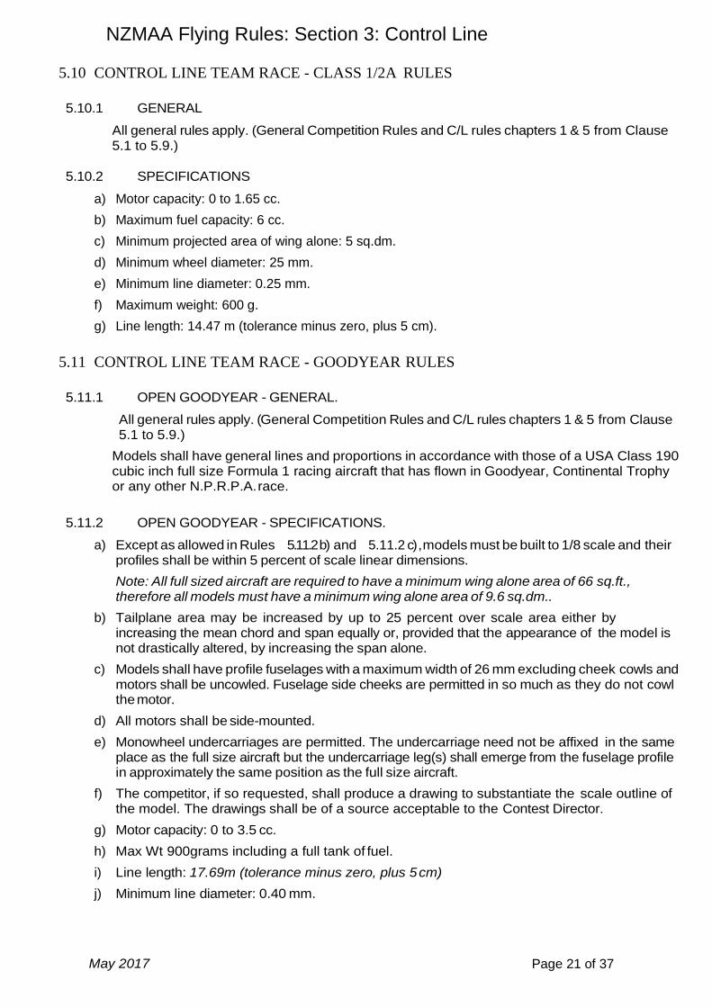
5.10 CONTROL LINE TEAM RACE - CLASS 1/2A RULES
5.10.1 GENERAL
All general rules apply. (General Competition Rules and C/L rules chapters 1 & 5 from Clause 5.1 to 5.9.)
5.10.2 SPECIFICATIONS
a) Motor capacity: 0 to 1.65 cc.
b) Maximum fuel capacity: 6 cc.
c) Minimum projected area of wing alone: 5 sq.dm.
d) Minimum wheel diameter: 25 mm.
e) Minimum line diameter: 0.25 mm.
f) Maximum weight: 600 g.
g) Line length: 14.47 m (tolerance minus zero, plus 5 cm).
5.11 CONTROL LINE TEAM RACE - GOODYEAR RULES
5.11.1 OPEN GOODYEAR - GENERAL.
All general rules apply. (General Competition Rules and C/L rules chapters 1 & 5 from Clause 5.1 to 5.9.)
Models shall have general lines and proportions in accordance with those of a USA Class 190 cubic inch full size Formula 1 racing aircraft that has flown in Goodyear, Continental Trophy or any other N.P.R.P.A. race.
5.11.2 OPEN GOODYEAR - SPECIFICATIONS.
a) Except as allowed in Rules 5.11.2 b) and 5.11.2 c) , models must be built to 1/8 scale and their profiles shall be within 5 percent of scale linear dimensions.
Note: All full sized aircraft are required to have a minimum wing alone area of 66 sq.ft., therefore all models must have a minimum wing alone area of 9.6 sq.dm..
b) Tailplane area may be increased by up to 25 percent over scale area either by increasing the mean chord and span equally or, provided that the appearance of the model is not drastically altered, by increasing the span alone.
c) Models shall have profile fuselages with a maximum width of 26 mm excluding cheek cowls and motors shall be uncowled. Fuselage side cheeks are permitted in so much as they do not cowl the motor.
d) All motors shall be side-mounted.
e) Monowheel undercarriages are permitted. The undercarriage need not be affixed in the same place as the full size aircraft but the undercarriage leg(s) shall emerge from the fuselage profile in approximately the same position as the full size aircraft.
f) The competitor, if so requested, shall produce a drawing to substantiate the scale outline of the model. The drawings shall be of a source acceptable to the Contest Director.
g) Motor capacity: 0 to 3.5 cc.
h) Max Wt 900grams including a full tank of fuel.
i) Line length: 17.69m (tolerance minus zero, plus 5 cm)
j) Minimum line diameter: 0.40 mm.
NZMAA Flying Rules: Section 3: Control Line
May 2017 Page 22 of 37
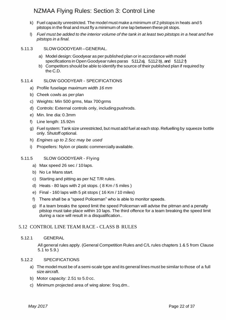
k) Fuel capacity unrestricted. The model must make a minimum of 2 pitstops in heats and 5 pitstops in the final and must fly a minimum of one lap between these pit stops.
l) Fuel must be added to the interior volume of the tank in at least two pitstops in a heat and five pitstops in a final.
5.11.3 SLOW GOODYEAR – GENERAL.
a) Model design: Goodyear as per published plan or in accordance with model
specifications in Open Goodyear rules paras 5.11.2 a), 5.11.2 b) , and 5.11.2 f) b) Competitors should be able to identify the source of their published plan if required by
the C.D.
5.11.4 SLOW GOODYEAR - SPECIFICATIONS
a) Profile fuselage maximum width 16 mm
b) Cheek cowls as per plan
c) Weights: Min 500 grms, Max 700 grms
d) Controls: External controls only, including pushrods.
e) Min. line dia: 0.3mm
f) Line length: 15.92m
g) Fuel system: Tank size unrestricted, but must add fuel at each stop. Refuelling by squeeze bottle only. Shutoff optional.
h) Engines up to 2.5cc may be used
i) Propellers: Nylon or plastic commercially available.
5.11.5 SLOW GOODYEAR - Flying
a) Max speed 26 sec / 10 laps.
b) No Le Mans start.
c) Starting and pitting as per NZ T/R rules.
d) Heats - 80 laps with 2 pit stops. ( 8 Km / 5 miles )
e) Final - 160 laps with 5 pit stops ( 16 Km / 10 miles)
f) There shall be a “speed Policeman” who is able to monitor speeds.
g) If a team breaks the speed limit the speed Policeman will advise the pitman and a penalty pitstop must take place within 10 laps. The third offence for a team breaking the speed limit during a race will result in a disqualification..
5.12 CONTROL LINE TEAM RACE - CLASS B RULES
5.12.1 GENERAL
All general rules apply. (General Competition Rules and C/L rules chapters 1 & 5 from Clause 5.1 to 5.9.)
5.12.2 SPECIFICATIONS
a) The model must be of a semi-scale type and its general lines must be similar to those of a full size aircraft.
b) Motor capacity: 2.51 to 5.0 cc.
c) Minimum projected area of wing alone: 9 sq.dm..

NZMAA Flying Rules: Section 3: Control Line
May 2017 Page 23 of 37
d) Maximum weight: 900 g.
e) Fuselage at the pilot's location: Min. height :100mm. Min. width :50 mm.
f) Minimum wheel diameter: 30 mm.
g) Maximum fuel capacity: 30 cc.
h) The motor(s) must be entirely enclosed including the cylinder head(s). The only parts permitted to protrude from the fuselage are the exhaust system(s) and those parts which have to be manipulated during the operation of starting the motor(s) or regulating controls (e.g. needle valve, tank fillers, fuel shut-off, compression lever, plugs, etc.).
i) Openings for the entry and exit of air, exhaust, etc., may be provided for the proper functioning of the motor(s). If a silencer is used, it may be fixed outside the fuselage.
j) A cockpit or cabin with transparent windshield giving direct visibility forward must be provided to house a scale model pilot which must be carried.
k) Line length: 17.69 m (tolerance minus zero, plus 5cm).Min. line diameter: 0.40 mm.
l) A spinner, if used, shall have a rounded front to minimise the risk of injury.
5.13 CONTROL LINE TEAM RACE - CLASSIC FAI RULES
Anything specific to Classic FAI will over-ride the NZ general rules, otherwise Control Line Team Racing General Rules apply.
5.13.1 The aim of Classic FAI team race is to re-create FAI team racing as it was before 1970, when in the eyes of many people, models were more beautiful, less expensive, and flew over grass at speeds most people can cope with. The intention is also to foster Trans Tasman competition with the Australians by keeping our rules compatible with theirs.
5.13.2 Definition of Classic Team Race Models - Model aeroplanes in which the propulsion energy is provided by a piston engine and in which the lift is obtained by aerodynamic forces acting on the supporting surfaces which must remain fixed during flight. The models must be of the semi-scale type and their general lines must be in accordance with those of full-size aircraft.
The choice of models designed before 1970 is encouraged, and such designs may be modified providing all other provisions of these rules are met.
"Own design" and designs never before published are allowed. Models must be of traditional wing and tail layout.
Flying wing type models are prohibited.
Asymmetry in the plan view is limited to a maximum of 15mm.
V tails are permitted.
Construction materials for models are unrestricted except for the following which are not allowed;
Components such as wings moulded from carbon fibre and all-metal wings
Aluminium or Magnesium pans are allowed.
5.13.1 Characteristics of Classic Team Racing Models:
a) Total maximum weight 700 grams
b) Maximum swept volume of engine 2.5 c.c.
c) Total surface (wing and stabiliser) minimum 12 sq. dms.

NZMAA Flying Rules: Section 3: Control Line
May 2017 Page 24 of 37
d) Minimum dimensions of the fuselage at the pilot's location:
Height 100 mm; Width 50 mm.
Minimum cross section area 39 sq.cm.
Wing fillets shall not be included in the fuselage cross sectional area.
e) The wheel or wheels shall have a minimum diameter of 25 mm. Landing gear must not be retractable. Mono wheel is permitted.
f) The tank complete with all connecting tubes must be accessible.
g) A single function valve is permitted. A multi-function valve may be used with the following restriction: The shut-off and needle valve are the only functions that can be used. Separate primes may be used.
h) Refuelling must be done with a hand held squeeze bottle. No pressure refuelling.
i) The combined capacity of the entire fuel feed system to the engine (tank, valve, tubing, filter etc.) is limited as follows:
j) T
k)
l)
m)
n)
o)
p) H j) The use of Tetraethyl Lead (TEL) and Ferocene is prohibited. The models must fly
anti-clockwise round the course. The motor or motors must be entirely enclosed including the cylinder head and the body of the carburettor (except the opening to the induction throat and a silencer-if fitted).
k) The only parts permitted to protrude from the body are those which have to be manipulated during the operation of starting the motor or regulating the mixture.(Fuel, needle valves, compression control, tank fillers, etc.) Openings for the entry and exit of air, exhaust, etc., may be provided for proper functioning of the motor/s.
l) Pilots must be able to stop and land the model within ten laps, when required by the Contest Director.
m) Currently acceptable engines are as above.
n) A transparent cockpit housing a pilots head is not mandatory, but is encouraged. A painted on cockpit as per F2C is allowed.
o) The undercarriage must be fixed in a permanent manner to the model so as to permit normal take-offs and landing. The use of a retracting undercarriage is prohibited.
p) Models need to be designed and constructed in such a manner as to be in the spirit of the rules.
q) Propellers are limited to commercially available nylon or glass reinforced plastic propellers . Propellers may be reduced in diameter or area over the outer half of each blade.
r) Graupner or APC 7x6 are suggested as a good starting point. Carbon or glass fibre props are prohibited.
tank capacity
15 cc Radial port engines such as Oliver, ETA and Webra etc. Also other designs used by Super Tigre, Enya and PAW etc. but not including schnuerle porting.
10 cc Fora Junior, Parra as currently used, K&B 15, Rossi and other pre-Nelson schnuerle port engines
7 cc Nelson 15 in any configuration. (Note Nelson 15 venturi max diam. 3.5 mm. )
NZMAA Flying Rules: Section 3: Control Line
May 2017 Page 25 of 37
s) Control Handle and Lines - Distance between the centre of the control handle and the centre line of the model shall be 15.92 metres +50mm, -0 mm. The diameter of the control lines must not be less than 0.381 mm (0.015 inches ). Single line (monoline) is not permitted.
5.13.2 Length of Course - The length of the course shall be 10 kilometres (100 laps) with two mandatory
refuelling stops except for a final which shall be 20 km. (200 laps) with five mandatory refuelling stops.

NZMAA Flying Rules: Section 3: Control Line
May 2017 Page 26 of 37
6. CONTROL LINE COMBAT GENERAL RULES
6.1 DEFINITIONS
a) Control Line Combat is a contest during which two models are flown at the same time in the same circle for a predetermined time, the object being to cut a paper streamer attached to the opponent’s model, points being awarded for each cut taken.
b) There is one New Zealand combat class: Speed Limited (Slow) Combat which is flown to FAI (F2D) rules.
6.2 NUMBER OF MODELS
a) Each competitor may have a maximum of two models in a contest, but only one of these models may be used in any one bout.
If both models are damaged during the elimination rounds in order for a fair final a third
model may be used for the final. Both Participants in a final will have the option of the use
of a third model.
No intentional sharp protuberances or devices for the purpose of cutting the streamer shall
be allowed. Projecting wing fences and/or top plates which are pointed, sharpened or
roughened, shall be considered devices for cutting streamers.
6.3 PULL TEST
A load test of 20 x the model weight shall be applied to the assembled control handle, lines and model, before each bout.
6.4 STREAMERS
a) Streamers are to be provided by the contest officials and must be between 2.25 & 3 metres in length, of crepe or similar toughened paper. The streamers should be of different colours to make judging easier. Judges must ensure that the streamers of both competitor’s in the bout are the same length before the bout commences.
b) There shall be no less than 2.5 metres of thread tether, between the aftermost portion of the model and the streamer.
c) The streamer shall be tethered at a point on the longitudinal line through the axis of the propeller.
6.5 DRAWING OF OPPONENTS AND STARTING
a) The contest shall be run as a knockout tournament.
b) The competitor who obtains the highest score in points shall be the winner of each bout.
c) A competitor shall be eliminated from the competition when he/she has lost two bouts.
d) Each round shall be randomly drawn from the competitors remaining in the competition.
e) In the event of an unmatched competitor remaining in any round, that competitor shall be matched with the first competitor drawn in the next round.
f) All signals shall be both acoustic and visual.
g) During the starting period the launching positions must be separated by at least a quarter of a lap. The first named competitor in the draw shall have the choice of streamer colour and the other the choice of starting position.
h) The motor(s) must be started by flicking the propeller by hand.
NZMAA Flying Rules: Section 3: Control Line
May 2017 Page 27 of 37
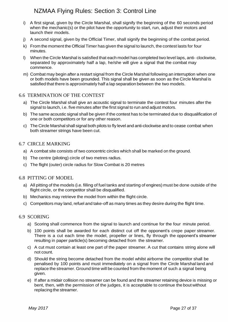
i) A first signal, given by the Circle Marshal, shall signify the beginning of the 60 seconds period when the mechanic(s) or the pilot have the opportunity to start, run, adjust their motors and launch their models.
j) A second signal, given by the Official Timer, shall signify the beginning of the combat period.
k) From the moment the Official Timer has given the signal to launch, the contest lasts for four minutes.
l) When the Circle Marshal is satisfied that each model has completed two level laps, anti- clockwise, separated by approximately half a lap, he/she will give a signal that the combat may commence.
m) Combat may begin after a restart signal from the Circle Marshal following an interruption when one or both models have been grounded. This signal shall be given as soon as the Circle Marshal is satisfied that there is approximately half a lap separation between the two models.
6.6 TERMINATION OF THE CONTEST
a) The Circle Marshal shall give an acoustic signal to terminate the contest four minutes after the signal to launch, i.e. five minutes after the first signal to run and adjust motors.
b) The same acoustic signal shall be given if the contest has to be terminated due to disqualification of one or both competitors or for any other reason.
c) The Circle Marshal shall signal both pilots to fly level and anti-clockwise and to cease combat when both streamer strings have been cut.
6.7 CIRCLE MARKING
a) A combat site consists of two concentric circles which shall be marked on the ground.
b) The centre (piloting) circle of two metres radius.
c) The flight (outer) circle radius for Slow Combat is 20 metres
6.8 PITTING OF MODEL
a) All pitting of the models (i.e. filling of fuel tanks and starting of engines) must be done outside of the flight circle, or the competitor shall be disqualified.
b) Mechanics may retrieve the model from within the flight circle.
c) Competitors may land, refuel and take-off as many times as they desire during the flight time.
6.9 SCORING
a) Scoring shall commence from the signal to launch and continue for the four minute period.
b) 100 points shall be awarded for each distinct cut off the opponent’s crepe paper streamer. There is a cut each time the model, propeller or lines, fly through the opponent’s streamer resulting in paper particle(s) becoming detached from the streamer.
c) A cut must contain at least one part of the paper streamer. A cut that contains string alone will not count.
d) Should the string become detached from the model whilst airborne the competitor shall be penalised by 100 points and must immediately on a signal from the Circle Marshal land and replace the streamer. Ground time will be counted from the moment of such a signal being given.
e) If after a midair collision no streamer can be found and the streamer retaining device is missing or bent, then, with the permission of the judges, it is acceptable to continue the bout without replacing the streamer.

NZMAA Flying Rules: Section 3: Control Line
May 2017 Page 28 of 37
f) One point shall be awarded for each whole second that a model is airborne during the four minute period.
g) Each whole second of stay on the ground of the model shall be penalised by one point. In the case of a model fly-away, with or without lines, this ground time shall commence from the moment of such a fly-away.
h) Each warnable offence (see 6.11) shall be penalised by the deduction of 40 points from the competitors score.
i) Should the mechanic(s) damage the streamer, or the model cut its own streamer whilst the model is on the ground, the mechanic(s) must replace it with a new streamer. If they launch the model without so replacing it the competitor shall be penalised 100 points. Ground time will be counted while the model is airborne with the damaged streamer.
j) In the event of a tie score in any bout, that bout shall be reflown. A bout is considered a tie if the score difference is 5 points or less.
6.10 GENERAL
a) A pilot must remain inside the centre circle while his/her model is flying except at the moment of release of his/her model by the pitman.
b) During the combat period each competitor (and his/her pit crew) shall be watched by at least one member of the jury specifically assigned to him/her, in addition to the Circle Marshal, to ensure that they behave in a fair manner according to the rules.
c) After a midair collision the bout shall continue as if both models had landed.
d) If a competitor at any time releases the control handle while the model is airborne, the competitor shall be disqualified. A wrist strap capable of withstanding 15kg pull test must be fitted and worn by the pilot whenever the model is airborne
e) Deliberate interference with an opponent or their control lines shall result in disqualification.
f) A circle marshal/starter and two scorers shall conduct the contest.
g) All mechanics must wear protective helmets and if any competitors leave the centre circle during a bout, they must also wear a protective helmet.
h) At championship events, the competitors will be placed by the bout wins minus the losses. (Highest positive number 1st etc.)
i) The pilot who shall be the entrant and known as the competitor, may employ a maximum of two mechanics. (In exceptional circumstances of wet or windy weather, an additional helper may be used as a streamer holder and must perform no other duty during the bout.)
6.11 OFFENCES
a) If a pilot unintentionally leaves the centre circle whilst his/her model is airborne.
b) If the mechanics enter the flying circle at an oblique angle or cut across the flying circle to reach a downed model. One penalty only will be incurred for each offence even if more than one mechanic is involved.
c) If the mechanic(s)/pilot do not immediately, or after a line disentanglement, withdraw a grounded model to outside the flight circle prior to servicing it.
d) If the model is launched prior to the first signal.
7. CONTROL LINE SLOW COMBAT RULES
7.1 GENERAL
NZMAA Flying Rules: Section 3: Control Line
May 2017 Page 29 of 37
All general rules apply. (General Competition Rules and C/L rules chapters 1 & 6
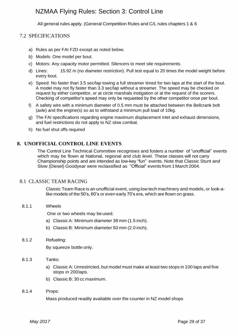
7.2 SPECIFICATIONS
a) Rules as per FAI F2D except as noted below.
b) Models: One model per bout.
c) Motors: Any capacity motor permitted. Silencers to meet site requirements.
d) Lines: 15.92 m (no diameter restriction). Pull test equal to 20 times the model weight before every bout.
e) Speed: No faster than 3.5 sec/lap towing a full streamer timed for two laps at the start of the bout. A model may not fly faster than 3.3 sec/lap without a streamer. The speed may be checked on request by either competitor, or at circle marshals instigation or at the request of the scorers. Checking of competitor’s speed may only be requested by the other competitor once per bout.
f) A safety wire with a minimum diameter of 0.5 mm must be attached between the Bellcrank bolt (axle) and the engine(s) so as to withstand a minimum pull load of 10kg.
g) The FAI specifications regarding engine maximum displacement inlet and exhaust dimensions, and fuel restrictions do not apply to NZ slow combat.
h) No fuel shut offs required
8. UNOFFICIAL CONTROL LINE EVENTS
The Control Line Technical Committee recognises and fosters a number of “unofficial” events which may be flown at National, regional and club level. These classes will not carry Championship points and are intended as low-key “fun” events. Note that Classic Stunt and Slow (Diesel) Goodyear were reclassified as “Official” events from 1 March 2004.
8.1 CLASSIC TEAM RACING
Classic Team Race is an unofficial event, using low tech machinery and models, or look-a-like models of the 50’s, 60’s or even early 70’s era, which are flown on grass.
8.1.1 Wheels
One or two wheels may be used.
a) Classic A: Minimum diameter 38 mm (1.5 inch).
b) Classic B: Minimum diameter 50 mm (2.0 inch).
8.1.2 Refueling:
By squeeze bottle only.
8.1.3 Tanks:
a) Classic A: Unrestricted, but model must make at least two stops in 100 laps and five stops in 200 laps.
b) Classic B: 30 cc maximum.
8.1.4 Props:
Mass produced readily available over the counter in NZ model shops
NZMAA Flying Rules: Section 3: Control Line
May 2017 Page 30 of 37
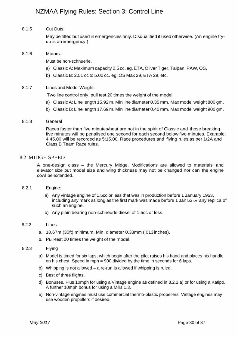
8.1.5 Cut Outs:
May be fitted but used in emergencies only. Disqualified if used otherwise. (An engine fry-up is an emergency.)
8.1.6 Motors:
Must be non-schnuerle.
a) Classic A: Maximum capacity 2.5 cc. eg. ETA, Oliver Tiger, Taipan, PAW, OS,
b) Classic B: 2.51 cc to 5.00 cc. eg. OS Max 29, ETA 29, etc.
8.1.7 Lines and Model Weight:
Two line control only, pull test 20 times the weight of the model.
a) Classic A: Line length 15.92 m. Min line diameter 0.35 mm. Max model weight 800 gm.
b) Classic B: Line length 17.69 m. Min line diameter 0.40 mm. Max model weight 900 gm.
8.1.8 General
Races faster than five minutes/heat are not in the spirit of Classic and those breaking five minutes will be penalised one second for each second below five minutes. Example: 4:45.00 will be recorded as 5:15.00. Race procedures and flying rules as per 1/2A and Class B Team Race rules.
8.2 MIDGE SPEED
A one-design class – the Mercury Midge. Modifications are allowed to materials and
elevator size but model size and wing thickness may not be changed nor can the engine cowl be extended.
8.2.1 Engine:
a) Any vintage engine of 1.5cc or less that was in production before 1 January 1953, including any mark as long as the first mark was made before 1 Jan 53 or any replica of such an engine.
b) Any plain bearing non-schneurle diesel of 1.5cc or less.
8.2.2 Lines
a. 10.67m (35ft) minimum. Min. diameter 0.33mm (.013 inches).
b. Pull-test 20 times the weight of the model.
8.2.3 Flying
a) Model is timed for six laps, which begin after the pilot raises his hand and places his handle on his chest. Speed in mph = 900 divided by the time in seconds for 6 laps.
b) Whipping is not allowed – a re-run is allowed if whipping is ruled.
c) Best of three flights.
d) Bonuses. Plus 10mph for using a Vintage engine as defined in 8.2.1 a) or for using a Katipo. A further 10mph bonus for using a Mills 1.3.
e) Non-vintage engines must use commercial thermo-plastic propellers. Vintage engines may use wooden propellers if desired.
NZMAA Flying Rules: Section 3: Control Line
May 2017 Page 31 of 37
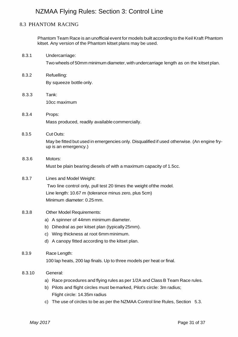
8.3 PHANTOM RACING
Phantom Team Race is an unofficial event for models built according to the Keil Kraft Phantom kitset. Any version of the Phantom kitset plans may be used.
8.3.1 Undercarriage:
Two wheels of 50mm minimum diameter, with undercarriage length as on the kitset plan.
8.3.2 Refuelling:
By squeeze bottle only.
8.3.3 Tank:
10cc maximum
8.3.4 Props:
Mass produced, readily available commercially.
8.3.5 Cut Outs:
May be fitted but used in emergencies only. Disqualified if used otherwise. (An engine fry-up is an emergency.)
8.3.6 Motors:
Must be plain bearing diesels of with a maximum capacity of 1.5cc.
8.3.7 Lines and Model Weight:
Two line control only, pull test 20 times the weight of the model.
Line length: 10.67 m (tolerance minus zero, plus 5cm)
Minimum diameter: 0.25 mm.
8.3.8 Other Model Requirements:
a) A spinner of 44mm minimum diameter.
b) Dihedral as per kitset plan (typically 25mm).
c) Wing thickness at root 6mm minimum.
d) A canopy fitted according to the kitset plan.
8.3.9 Race Length:
100 lap heats, 200 lap finals. Up to three models per heat or final.
8.3.10 General:
a) Race procedures and flying rules as per 1/2A and Class B Team Race rules.
b) Pilots and flight circles must be marked, Pilot's circle: 3m radius;
Flight circle: 14.35m radius
c) The use of circles to be as per the NZMAA Control line Rules, Section 5.3.
NZMAA Flying Rules: Section 3: Control Line
May 2017 Page 32 of 37
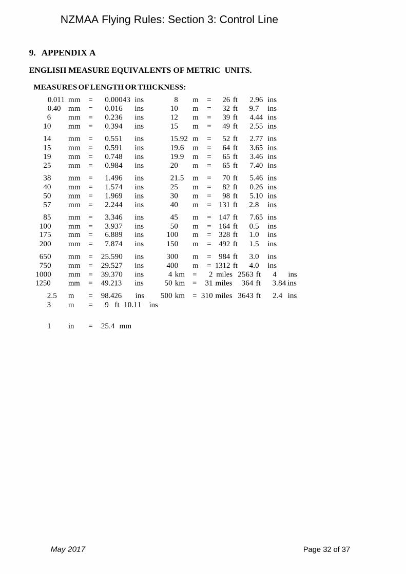
9. APPENDIX A
ENGLISH MEASURE EQUIVALENTS OF METRIC UNITS.
MEASURES OF LENGTH OR THICKNESS:
0.011 mm = 0.00043 ins 8 m = 26 ft 2.96 ins
0.40 mm = 0.016 ins 10 m = 32 ft 9.7 ins
6 mm = 0.236 ins 12 m = 39 ft 4.44 ins
10 mm = 0.394 ins 15 m = 49 ft 2.55 ins
14 mm = 0.551 ins 15.92 m = 52 ft 2.77 ins
15 mm = 0.591 ins 19.6 m = 64 ft 3.65 ins
19 mm = 0.748 ins 19.9 m = 65 ft 3.46 ins
25 mm = 0.984 ins 20 m = 65 ft 7.40 ins
38 mm = 1.496 ins 21.5 m = 70 ft 5.46 ins
40 mm = 1.574 ins 25 m = 82 ft 0.26 ins
50 mm = 1.969 ins 30 m = 98 ft 5.10 ins
57 mm = 2.244 ins 40 m = 131 ft 2.8 ins
85 mm = 3.346 ins 45 m = 147 ft 7.65 ins
100 mm = 3.937 ins 50 m = 164 ft 0.5 ins 175 mm = 6.889 ins 100 m = 328 ft 1.0 ins
200 mm = 7.874 ins 150 m = 492 ft 1.5 ins
650 mm = 25.590 ins 300 m = 984 ft 3.0 ins
750 mm = 29.527 ins 400 m = 1312 ft 4.0 ins
1000 mm = 39.370 ins 4 km = 2 miles 2563 ft 4 ins
1250 mm = 49.213 ins 50 km = 31 miles 364 ft 3.84 ins
2.5 m = 98.426 ins 500 km = 310 miles 3643 ft 2.4 ins
3
5 m
m
=
=
9 ft 10.11
16 ft 4.85 ins
ins
1 in = 25.4 mm
NZMAA Flying Rules: Section 3: Control Line
May 2017 Page 33 of 37
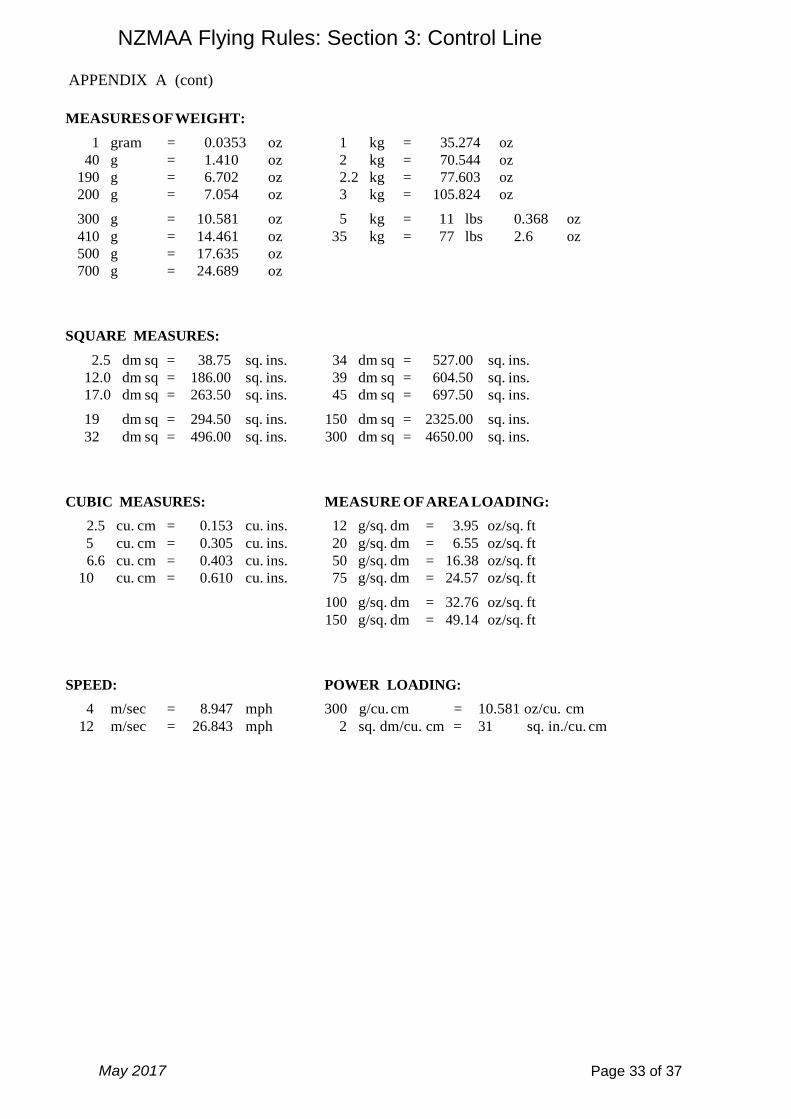
APPENDIX A (cont)
MEASURES OF WEIGHT:
1 gram = 0.0353 oz 1 kg = 35.274 oz
40 g = 1.410 oz 2 kg = 70.544 oz
190 g = 6.702 oz 2.2 kg = 77.603 oz
200 g = 7.054 oz 3 kg = 105.824 oz
300 g = 10.581 oz 5 kg = 11 lbs 0.368 oz
410 g = 14.461 oz 35 kg = 77 lbs 2.6 oz
500 g = 17.635 oz 700 g = 24.689 oz
SQUARE MEASURES:
2.5 dm sq = 38.75 sq. ins. 34 dm sq = 527.00 sq. ins.
12.0 dm sq = 186.00 sq. ins. 39 dm sq = 604.50 sq. ins.
17.0 dm sq = 263.50 sq. ins. 45 dm sq = 697.50 sq. ins.
19 dm sq = 294.50 sq. ins. 150 dm sq = 2325.00 sq. ins.
32 dm sq = 496.00 sq. ins. 300 dm sq = 4650.00 sq. ins.
CUBIC MEASURES: MEASURE OF AREA LOADING:
2.5 cu. cm = 0.153 cu. ins. 12 g/sq. dm = 3.95 oz/sq. ft
5 cu. cm = 0.305 cu. ins. 20 g/sq. dm = 6.55 oz/sq. ft
6.6 cu. cm = 0.403 cu. ins. 50 g/sq. dm = 16.38 oz/sq. ft
10 cu. cm = 0.610 cu. ins. 75 g/sq. dm = 24.57 oz/sq. ft
100 g/sq. dm = 32.76 oz/sq. ft
150 g/sq. dm = 49.14 oz/sq. ft
SPEED: POWER LOADING:
4 m/sec = 8.947 mph 300 g/cu. cm = 10.581 oz/cu. cm
12 m/sec = 26.843 mph 2 sq. dm/cu. cm = 31 sq. in./cu. cm

NZMAA Flying Rules: Section 3: Control Line
May 2017 Page 34 of 37
10. APPENDIX B
SPEED CONVERSION CHART
This chart enables an easy conversion to be made between the time taken for a model to fly 1
km and its resultant speed in km/h or mph. 1km is 11 laps on 14.47 m lines, 10 laps on 15.92 m
lines, 9 laps on 17.69 m lines and 8 laps on 19.90 m lines.
Speed (km/h) = 3600 divided by time in secs for 1km Speed (mph) =
2236.9 divided by time in secs for 1km
- - - - - - - - - - - - - - - -
Secs km/h mph
- - - - - - - - - - - - - - - -
- - - - - - - - - - - - - - - -
Secs km/h mph
- - - - - - - - - - - - - - - -
- - - - - - - - - - - - - - - -
Secs km/h mph
- - - - - - - - - - - - - - - -
11.0 327.3 203.4 13.0 276.9 172.1 15.0 240.0 149.1
11.1 324.3 201.5 13.1 274.8 170.8 15.1 238.4 148.1
11.2 321.4 199.7 13.2 272.7 169.5 15.2 236.8 147.2
11.3 318.6 198.0 13.3 270.7 168.2 15.3 235.3 146.2
11.4 315.8 196.2 13.4 267.7 166.9 15.4 233.8 145.3
11.5 313.0 194.5 13.5 266.7 165.7 15.5 232.3 144.3
11.6 310.3 192.8 13.6 264.7 164.5 15.6 230.8 143.4
11.7 307.7 191.2 13.7 262.8 163.3 15.7 229.3 142.5
11.8 305.1 189.6 13.8 260.9 162.1 15.8 227.8 141.6
11.9 302.5 188.0 13.9 259.0 160.9 15.9 226.4 140.7
12.0 300.0 186.4 14.0 257.1 159.8 16.0 225.0 139.8
12.1 297.5 184.9 14.1 255.3 158.7 16.1 223.6 138.9
12.2 295.1 183.4 14.2 253.5 157.5 16.2 222.2 138.1
12.3 292.7 181.9 14.3 251.7 156.4 16.3 220.9 137.2
12.4 290.3 180.4 14.4 250.0 155.4 16.4 219.5 136.4
12.5 288.0 179.0 14.5 248.3 154.3 16.5 218.2 135.6
12.6 285.7 177.5 14.6 246.6 153.2 16.6 216.9 134.8
12.7 283.5 176.1 14.7 244.9 152.2 16.7 215.6 134.0
12.8 281.3 174.8 14.8 243.2 151.2 16.8 214.3 133.2
12.9 279.1 173.4 14.9 241.6 150.1 16.9 213.0 132.4

NZMAA Flying Rules: Section 3: Control Line
May 2017 Page 35 of 37
APPENDIX B (cont)
- - - - - - - - - - - - - - - -
Secs km/h mph
- - - - - - - - - - - - - - - -
- - - - - - - - - - - - - - - -
Secs km/h mph
- - - - - - - - - - - - - - - -
- - - - - - - - - - - - - - - -
Secs km/h mph
- - - - - - - - - - - - - - - -
17.0 211.8 131.6 20.0 180.0 111.9 23.0 156.5 97.3
17.1 210.5 130.8 20.1 179.1 111.3 23.1 155.8 96.8
17.2 209.3 130.1 20.2 178.2 110.7 23.2 155.2 96.4
17.3 208.1 129.3 20.3 177.3 110.2 23.3 154.5 96.0
17.4 206.9 128.6 20.4 176.5 109.7 23.4 153.8 95.6
17.5 205.7 127.8 20.5 175.6 109.1 23.5 153.2 95.2
17.6 204.5 127.1 20.6 174.8 108.6 23.6 152.5 94.8
17.7 203.4 126.4 20.7 173.9 108.1 23.7 151.9 94.4
17.8 202.2 125.7 20.8 173.1 107.5 23.8 151.3 94.0
17.9 201.1 125.0 20.9 172.2 107.0 23.9 150.6 93.6
18.0 200.0 124.3 21.0 171.4 106.5 24.0 150.0 93.2
18.1 198.9 123.6 21.1 170.6 106.0 24.1 149.4 92.8
18.2 197.8 122.9 21.2 169.8 105.5 24.2 148.8 92.4
18.3 196.7 122.2 21.3 169.0 105.0 24.3 148.1 92.1
18.4 195.7 121.6 21.4 168.2 104.5 24.4 147.5 91.7
18.5 194.6 120.9 21.5 167.4 104.0 24.5 146.9 91.3
18.6 193.5 120.3 21.6 166.7 103.6 24.6 146.3 90.9
18.7 192.5 119.6 21.7 165.9 103.1 24.7 145.7 90.6
18.8 191.5 119.0 21.8 165.1 102.6 24.8 145.2 90.2
18.9 190.5 118.4 21.9 164.4 102.1 24.9 144.6 89.8
19.0 189.5 117.7 22.0 163.6 101.7 25.0 144.0 89.5
19.1 188.5 117.1 22.1 162.9 101.2 25.1 143.4 89.1
19.2 187.5 116.5 22.2 162.2 100.8 25.2 142.9 88.8
19.3 186.5 115.9 22.3 161.4 100.3 25.3 142.3 88.4
19.4 185.6 115.3 22.4 160.7 99.9 25.4 141.7 88.1
19.5 184.6 114.7 22.5 160.0 99.4 25.5 141.2 87.7
19.6 183.7 114.1 22.6 159.3 99.0 25.6 140.6 87.4
19.7 182.7 113.6 22.7 158.6 98.5 25.7 140.1 87.0
19.8 181.8 113.0 22.8 157.9 98.1 25.8 139.5 86.7
19.9 180.9 112.4 22.9 157.2 97.7 25.9 139.0 86.4

NZMAA Flying Rules: Section 3: Control Line
May 2017 Page 36 of 37
APPENDIX B (cont)
- - - - - - - - - - - - - - - -
Secs km/h mph
- - - - - - - - - - - - - - - -
- - - - - - - - - - - - - - - -
Secs km/h mph
- - - - - - - - - - - - - - - -
- - - - - - - - - - - - - - - -
Secs km/h mph
- - - - - - - - - - - - - - - -
26.0 138.5 86.0 29.0 124.1 77.1 32.0 112.5 69.9
26.1 137.9 85.7 29.1 123.7 76.9 32.1 112.1 69.7
26.2 137.4 85.4 29.2 123.3 76.6 32.2 111.8 69.5
26.3 136.9 85.1 29.3 122.9 76.3 32.3 111.5 69.3
26.4 136.4 84.7 29.4 122.4 76.1 32.4 111.1 69.0
26.5 135.8 84.4 29.5 122.0 75.8 32.5 110.8 68.8
26.6 135.3 84.1 29.6 121.6 76.6 32.6 110.4 68.6
26.7 134.8 83.8 29.7 121.2 75.3 32.7 110.1 68.4
26.8 134.3 83.5 29.8 120.8 75.1 32.8 109.8 68.2
26.9 133.8 83.2 29.9 120.4 74.8 32.9 109.4 68.0
27.0 133.3 82.9 30.0 120.0 74.6 33.0 109.1 67.8
27.1 132.8 82.5 30.1 119.6 74.3 33.1 108.8 67.6
27.2 132.4 82.2 30.2 119.2 74.1 33.2 108.4 67.4
27.3 131.9 81.9 30.3 118.8 73.8 33.3 108.1 67.2
27.4 131.4 81.6 30.4 118.4 73.6 33.4 107.8 67.0
27.5 130.9 81.3 30.5 118.0 73.3 33.5 107.5 66.8
27.6 130.4 81.1 30.6 117.6 73.1 33.6 107.1 66.6
27.7 130.0 80.8 30.7 117.3 72.9 33.7 106.8 66.4
27.8 129.5 80.5 30.8 116.9 72.6 33.8 106.5 66.2
27.9 129.0 80.2 30.9 116.5 72.4 33.9 106.2 66.0
28.0 129.6 79.9 31.0 116.1 72.2 34.0 105.9 65.8
28.1 128.1 79.6 31.1 115.8 71.9 34.1 105.6 65.6
28.2 127.7 79.3 31.2 115.4 71.7 34.2 105.3 65.4
28.3 127.2 79.0 31.3 115.0 71.5 34.3 105.0 65.2
28.4 126.8 78.8 31.4 114.6 71.2 34.4 104.7 65.0
28.5 126.3 78.5 31.5 114.3 71.0 34.5 104.3 64.8
28.6 125.9 78.2 31.6 113.9 70.8 34.6 104.0 64.7
28.7 125.4 77.9 31.7 113.6 70.6 34.7 103.7 64.5
28.8 125.0 77.7 31.8 113.2 70.3 34.8 103.4 64.3
28.9 124.6 77.4 31.9 112.9 70.1 34.9 103.2 64.1
35.0
102.9
63.9
35.4
101.7
63.2
35.1 102.6 63.7 35.5 101.4 63.0 35.8 100.6 62.5
35.2 102.3 63.6 35.6 101.1 62.8 35.9 100.3 62.3
35.3 102.0 63.4 35.7 100.8 62.7 36.0 100.0 62.1

NZMAA Flying Rules: Section 3: Control Line
May 2017 Page 37 of 37
11. APPENDIX C CONTROL LINE PULL TEST CHART
PULL TEST (In kg) MODEL
WEIGHT
FAI F2B STUNT,
SPORTSMAN
STUNT, &
CLASSIC STUNT
1/2 A T/R,
SLOW COMBAT,
CLASSIC T/R,
MIDGE SPEED, &
PHANTOM
RACING
SLOW
GOODYEAR,
OPEN
GOODYEAR
& B T/R
FAI F2C
& F2F
T/R
NZ
SPEED
FAI F2A
SPEED
(grams) (x 10) (x 20) (x 25) (x 30) (x 40) (x 50)
200 2 4 5 6 8 10
250 2.5 5 6.25 7.5 10 12.5
300 3 6 7.5 9 12 15
350 3.5 7 8.75 10.5 14 17.5
400 4 8 10 12 16 20
450 4.5 9 11.25 13.5 18 22.5
500 5 10 12.5 15 20 25
550 5.5 11 13.75 22 27.5
600 6 12 15 24 30
650 6.5 13 16.25 26 32.5
700 7 14 17.5 28 35
750 7.5 15 18.75 30 37.5
800 8 16 20 32 40
850 8.5 17 21.25 34
900 9 18 22.5 36
950 9.5 38
1000 10 40
1100 11 44
1200 12 48
1300 13 52
1400 14 56
1500 15
1600 16
1700 17
1800 18
1900 19
2000 20
NOTES: July 2015
1) Pull Test for FAI F2D COMBAT is 20 kg irrespective of model weight.
2) Maximum pull tests are:- a) 1/2 A Team Race 12 kg h) Class 2 Speed 32 kg. b) Slow Goodyear T/R 17.5 kg. i) Class 3 Speed 40 kg c) Open Goodyear T/R 22.5 kg. j) Class 4 & 5 Speed 56 kg. d) B Team Race 22.5 kg. k) FAI F2A Speed 30 kg e) Classic A Team Race 16 kg. l) FAI F2B Aerobatics 35 kg f) Classic B Team Race 18 kg. m) FAI F2C Team Race 14 kg g) Class 1 Speed 20 kg. n) FAI F2F Team Race 14 kg
Related Documents