Report CTV Building Drag Bar Capacity Assessment Prepared for Canterbury Earthquakes Royal Commission By Beca Infrastructure Ltd (Beca) 1 June 2012 © Beca 2012 (unless Beca has expressly agreed otherwise with the Client in writing). This report has been prepared by Beca on the specific instructions of our Client. It is solely for our Client’s use for the purpose for which it is intended in accordance with the agreed scope of work. Any use or reliance by any person contrary to the above, to which Beca has not given its prior written consent, is at that person's own risk. BUI.MAD249.0431.1

Welcome message from author
This document is posted to help you gain knowledge. Please leave a comment to let me know what you think about it! Share it to your friends and learn new things together.
Transcript
Report
CTV Building Drag Bar Capacity Assessment Prepared for Canterbury Earthquakes Royal Commission
By Beca Infrastructure Ltd (Beca)
1 June 2012
© Beca 2012 (unless Beca has expressly agreed otherwise with the Client in writing).
This report has been prepared by Beca on the specific instructions of our Client. It is solely for our Client’s use for the purpose for which it is intended in accordance with the agreed scope of work. Any use or reliance by any person contrary to the above, to which Beca has not given its prior written consent, is at that person's own risk.
BUI.MAD249.0431.1

BUI.MAD249.0431.2
CTV Building Drag Bar Capacity Assessment
Beca // 29 May 2012 // Page 1
3910814 // NZ1-5935587-9 1.1
Table of Contents 1 Introduction .......................................................................................................... 2
2 Basis of Assessment ............................................................................................ 2
3 Failure Modes Investigated .................................................................................. 3
4 Capacity Assessments ......................................................................................... 3 4.1 References for capacity assessment ........................................................................... 3 4.2 Capacity Reduction Factors ......................................................................................... 4 4.3 Governing Modes of Failure and Capacities ................................................................ 4 4.4 Drag Bar Capacity Summary ....................................................................................... 8
5 Other Issues Potentially Affecting Capacity ....................................................... 8
6 Closing Comments ............................................................................................... 9
Appendices Appendix A - Figures
BUI.MAD249.0431.3
CTV Building Drag Bar Capacity Assessment
Beca // 29 May 2012 // Page 2
3910814 // NZ1-5935587-9 1.1
1 Introduction Beca Infrastructure Ltd was commissioned by the Canterbury Earthquakes Royal Commission (the Royal Commission) on 18 May 2012 to carry out an assessment of the capacity of the CTV Building Drag Bars. The scope was to assess the tension capacity of the drag bars depicted on pages 270 and 271 of the CTV Building Collapse Report prepared by Hyland Consultants Ltd and StructureSmith Ltd. The assessment was to consist of the following steps:
• Independently calculate drag bar, wall anchor and slab anchor capacities, using NZS 3404 and FIB Bulletin 58 and drawings, dimensions and material properties supplied by the Royal Commission..
• Calculate anchor capacities using Ramset (supplier of Chemset) technical literature and compare.
• Consider whether any aspects of the detailing may invalidate the calculated capacities (for example the RHS packer shown in the details, the number of anchors to be mobilized, the eccentricity of the connection to the drag bar centroid) and comment
• Consider whether slab or wall strength (tensile strength or splitting strength) rather than drag bar strength may limit the tensions able to be carried
• Consider the effects of possible poor adhesion of the anchors into the drilled holes due to poor workmanship at the time of installation (a recognized problem with this type of anchor) or time dependent deterioration and comment.
• Produce a report summarizing our findings
This document is a final report,. The assessment has been carried out independently and the findings have not been discussed with any other parties, including the authors of the Collapse Report.
2 Basis of Assessment The CTV building ‘drag bars’ connected the floors at Levels 4, 5 and 6 to the North Core walls on Lines D and D/E. The drag bars were retrofitted to the building in 1990 and consist of steel angles fixed to the floor slab and walls using Chemset type bonded anchors (steel studs adhesive fixed into holes drilled in the concrete). Our assessment was based on dimensions and material properties sourced from the CTV Building Collapse Investigation Report prepared by Hyland Consultants Ltd and StructureSmith Ltd and the CTV Building Site Examination and Materials Tests Report prepared by Hyland Consultants Ltd, supplemented by some additional information not in the reports that was supplied directly by Hyland Consultants Ltd. It has been assumed that Ramset Chemset capsules were used as the anchor adhesive and that similar bond properties to those implied in the current Ramset Chemical Anchoring Resource Book are applicable. Discussion with a Ramset Product Manager has indicated that the latter is a reasonable assumption. Information used is summarised as follows (strengths quoted are characteristic strengths):
BUI.MAD249.0431.4

CTV Building Drag Bar Capacity Assessment
Beca // 29 May 2012 // Page 3
3910814 // NZ1-5935587-9 1.1
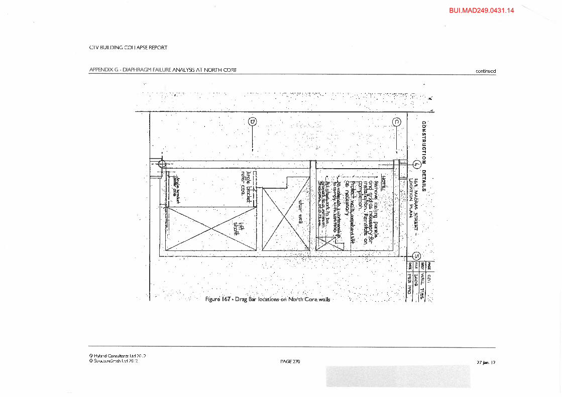
• Drag bar and anchor details as shown in Figures 167 and 168 of the Collapse Report (reproduced in Figures 1 and 2 of this report)
• Slab and wall dimensions and reinforcement as shown on Drawings S11, S15 and S16 contained in Appendix L of the Collapse Report
• Concrete strength for slab and walls of 25 MPa • Reinforcement grades of 380 MPa for H bars and 485 MPa for 664 mesh • Hi-bond decking 0.75mm BMT, 550 MPa yield • Drag bar steelwork (steel angle section and RHS) 250 MPa yield, 400 MPa UTS • Chemset studs Grade 5.8, 520 MPa UTS, 145mm embedment in slab and walls • Ultimate anchor bond strength of 10 MPa, based on back calculation from Ramset
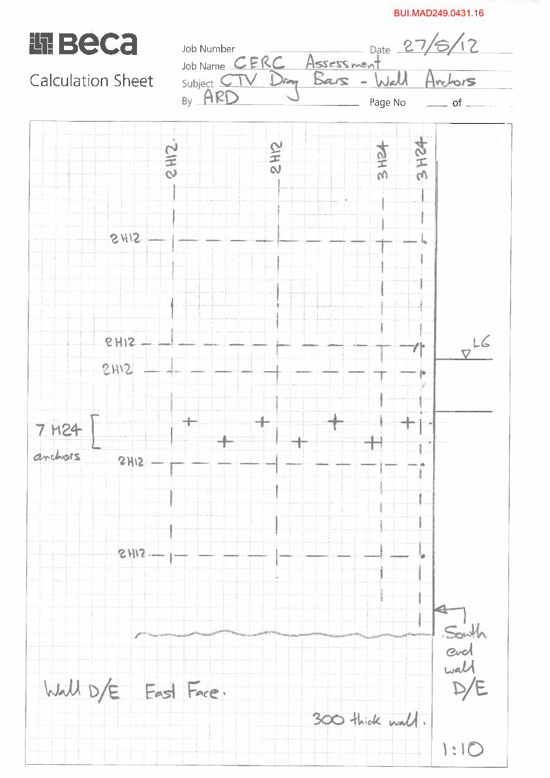
capacities Information relevant to each different anchor group at Level 6 is summarised in the sketches shown in Figures 3, 4 and 5.
3 Failure Modes Investigated Failure modes assessed included:
• Drag bar tensile failure • Shear load failure of anchors (see below) • Pullout of portion of wall or slab in which anchor group is located
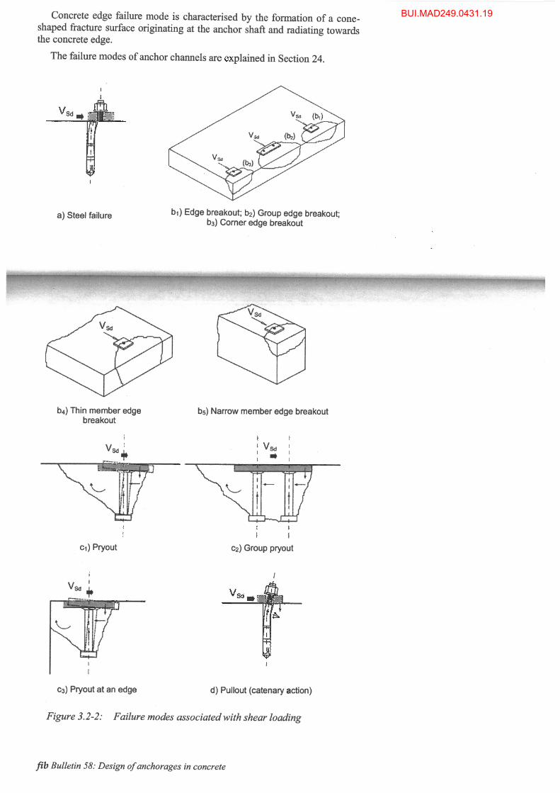
FIB 58 describes and assists capacity assessment for the following shear load failure modes (refer Figure 6):
• Steel failure (shear failure of anchor stud) • Pryout (of concrete cone) • Pullout (of anchor) • Edge breakout (in direction of loading or perpendicular to direction of loading)
FIB 58 distinguishes for shear loading between anchor groups with zero hole clearance for the anchor studs in the fastened plate, ‘normal’ hole clearance (typically 2mm) and greater than normal clearance, and gives assessment recommendations for each type of group. The significance of this is that the anchor displacement required to initiate edge breakout is small, and so where hole clearance is present it is possible for only some anchors in the group to be loaded when edge breakout occurs, reducing the overall capacity of the group. In addition to the above basic failure modes, consideration was given to the additional detailing issues listed in Section 1 and the effect they might have on capacities.
4 Capacity Assessments
4.1 References for capacity assessment The assessment of the capacity of bonded anchors such as those utilised for the retrofitting of the CTV drag bars is not covered by the New Zealand Standards used by structural designers in New Zealand. (Capacity assessment for cast-in anchors is addressed in NZS 3101:2006, but was not covered by previous versions of this code). Designers usually refer to capacity data provided by the suppliers of bonded anchors – an example of which is the Ramset Specifiers Anchoring Resource Book, which covers Chemset anchors.
BUI.MAD249.0431.5
CTV Building Drag Bar Capacity Assessment
Beca // 29 May 2012 // Page 4
3910814 // NZ1-5935587-9 1.1
The FIB Bulletin 58 - Design of Anchorages In Concrete is a ‘state-of-the-art’ guide to good practice published in July 2011. It is a substantial revision of a 1996 document and includes bonded anchors for the first time. The preface to the document notes that “despite the widespread use of cast-in-place and post-installed anchors in construction, the overall level of understanding in the engineering community regarding their behaviour remains quite limited”. This assessment utilised both the current Ramset Resource Book (Book 3.4 dated 2010) and FIB 58, but placed most reliance on FIB 58 because the Ramset document covers a relatively limited range of situations. However, even FIB 58 has limits on its scope of application. The configuration and/or number of anchors in the groups utilised for the CTV drag bars fall outside these limits and so, in the words of the Bulletin “the provisions have been applied with engineering judgement”. It is important to note that the FIB 58 capacities are based on the assumption that when the anchorage reaches the ultimate limit state, the structural element that takes up the loads is at or below the serviceability limit state. No attempt has been made in this assessment to determine the extent to which this assumption is valid in the case of the CTV building. However some comment is provided in Section 6. Drag bar tension capacities were assessed using NZS 3404. Pullout capacities of portions of wall or slab were assessed using NZS 3101.
4.2 Capacity Reduction Factors FIB 58 (and the Ramset Resource Book) require the application of partial factors (or capacity reduction factors) to characteristic resistances to achieve design resistance values. The factors (expressed as capacity reduction factors) are 0.8 for steel resistance and 0.67 (FIB) or 0.6 (Ramset) for failure modes governed by concrete capacity. NZS 3101 (for cast-in anchors) uses 0.75 for all shear capacities and 0.65 for all tension capacities, irrespective of whether governed by steel failure or concrete failure. It is understood that the relatively low factors reflect the reliance of anchors on the tensile strength of concrete for their capacity. In addition, FIB 58 recommends the use of a seismic reduction factor of 0.75 to obtain seismic resistance values from static capacities. In order to be consistent with the drag bar capacities quoted on page 266 of the Collapse Report, the above factors have not been applied to the capacities quoted below. FIB 58 requires that for seismic capacity assessment, the concrete in which the anchors are located is considered to be cracked for the purpose of edge breakout and pryout assessment, which results in a 30% reduction in capacity as compared with uncracked concrete. This requirement was followed. The document also requires the use of a reduced pullout bond value for cracked concrete as compared with uncracked concrete, but does not prescribe values for either. As described above, a value of 10 MPa has been deduced from Ramset capacity data and used for this assessment.
4.3 Governing Modes of Failure and Capacities Drag bar tension capacity was not found to govern load capacity at any location. Capacity was assessed at 876 kN for the Wall D drag bars and 518 kN for the Wall D/E drag bars.
BUI.MAD249.0431.6

CTV Building Drag Bar Capacity Assessment
Beca // 29 May 2012 // Page 5
3910814 // NZ1-5935587-9 1.1
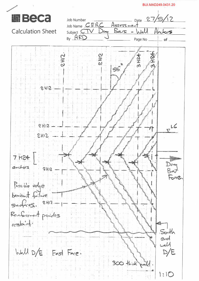
4.3.1 Wall anchor groups Assessment was initially carried out on the wall D/E Level 6 group, this having the most anchors. Capacities quoted below were assessed using the FIB 58 document unless noted otherwise. The maximum capacity per M24 anchor is 88 kN based on steel failure, and thus an upper bound capacity for the group of seven anchors is 616 kN. We note that the steel failure capacity of 88 kN is lower than that which would be obtained for a bolt of the same properties using NZS 3404. This is because FIB 58 uses 0.5 x As x UTS rather than 0.62 x As x UTS as per NZS 3404 (where in this case As is the minor diameter area of the threaded bar). FIB 58 notes “steel failure is accompanied by crushing and spalling of the concrete ahead of the anchor. The effect of the resulting secondary tensile and flexural stresses in the anchor bolt is accounted for in the design model for steel resistance”. Initially the presence of reinforcement in the wall was ignored. The critical failure mode was found to be concrete edge failure, with the anchor closest to the edge having a calculated capacity of 18 kN and the group as a whole (seven anchors) a capacity of 163 kN. An assessment was then carried out of the ability of the wall horizontal reinforcement to prevent edge failure after cracking. It was found that with the exception of the anchor closest to the edge, the reinforcement present within the edge failure wedges was adequate to make edge failure non-governing. Refer to the sketch in Figure 7 for failure surfaces, based on FIB 58. The assessment then indicated that concrete pry-out failure was critical for most anchors. FIB 58 states (for anchors of greater than 60mm effective length) that the shear pry-out failure load is simply twice the cone failure capacity in tension. Because of the relatively close anchor spacing, the calculated tension capacities of the wall anchors are relatively low and this follows through to the calculated pry-out capacities of 43 kN per anchor (as compared with 134 kN for a single anchor in cracked concrete and 192 kN in uncracked concrete). It seems that the interaction of closely spaced anchors in shear along the line of anchors would be such as to suppress pry-out failures of adjacent anchors rather than promote them and hence this result does not seem logical (whereas it would be for shear perpendicular to the line of anchors). This reduction is not present in Ramset recommendations. Thus the 43 kN pry-out capacity has been ignored for the purpose of this assessment. In this regard the assessment thus departs from FIB 58. The next most critical capacity was calculated at 72 kN per anchor based on anchor pullout. Again this is based on adverse interaction of closely spaced anchors (224 kN is obtained for a single anchor) and may perhaps be overly conservative. However it has been assumed that the 72 kN may be correct for the purpose of this assessment. Group capacity was then assessed based on 20 kN for the anchor closest to the edge (assuming a residual post-edge breakout capacity due to the presence of vertical reinforcing bars) and 72 to 88 kN (pullout or steel failure) for the remainder, giving 450-550 kN for the group as a whole. It has been assumed that as the group capacity is not based on un-reinforced edge breakout, that the influence of hole clearance will not be detrimental, with pull-out or steel failure modes involving enough displacement for hole clearances to be taken up. This is supported by FIB 58. Assessment for the remaining wall groups, with fewer anchors, was carried out on a similar basis. Assessment using the Ramset Resource Book indicated a higher maximum shear capacity per anchor based on steel failure, of 109 kN (compared with 88 kN) and a considerably higher edge breakout capacity for the group of 455 kN (compared with 163 kN). The Ramset capacities do not appear to take into account the finite thickness of a concrete element, and, as noted above, also
BUI.MAD249.0431.7
CTV Building Drag Bar Capacity Assessment
Beca // 29 May 2012 // Page 6
3910814 // NZ1-5935587-9 1.1
appear to assume that provided an anchor is embedded by six diameters, pullout or pry-out will not govern, regardless of spacing. The summary capacities presented in Table 1 below are based on the FIB 58 capacities.
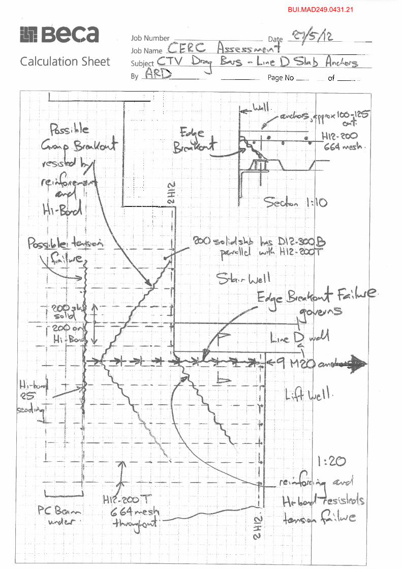
4.3.2 Slab Anchor Groups on Line D Assessment was initially carried out on the Wall D Level 6 group, this having the most anchors. Capacities quoted below were assessed using the FIB 58 document unless noted otherwise. The maximum capacity per M20 anchor is 61 kN based on steel failure, and thus the upper bound capacity for the group of nine anchors is 549 kN. However, the capacity of the five anchors immediately adjacent to the wall (refer Figure 8) is limited by edge breakout perpendicular to the direction of loading, and a capacity of 33 kN per anchor was assessed for these anchors. For the anchors in the body of the slab, the steel failure capacity of 61 kN is less than pryout or pullout capacities. The reinforcing steel, mesh and Hi-Bond decking between them have been assessed to provide sufficient tensile capacity to prevent edge breakout of the entire anchor group. In order to assess the capacity of the anchor group as a whole the post-breakout capacity of the anchors adjacent to the wall requires consideration. At the time breakout occurs, it seems reasonable to assume that all nine anchors are carrying the same load, of 33 kN each, giving a total of 299 kN. With further displacement the load in the four anchors in the body of the slab can increase to 61 kN each, but the load carried by the five anchors adjacent to the wall at that displacement is not able to be determined from FIB 58 and would require access to load-deformation data for similar situations. However, with reference to Figure 8, the wedge of concrete created by the breakout failure cannot fall away due to the presence of the wall and the drag bar and the Hi-Bond sheet will exert force on the anchor, so some residual capacity can be expected. In the absence of any guidance, judgement has been applied and it has been assumed that the anchors achieve a residual capacity of 10-30 kN. The post-breakout capacity of the anchor group has thus been assessed as four anchors @ 61 kN plus five @ 10-30 kN, giving a total of 294-394 kN. The 294 kN is slightly lower than the breakout capacity of 299 kN and thus the group capacity is assessed at 299-394 kN. The Hi-Bond decking stops at the Line 4 beam, and so a potential line of weakness exists along this interface, with only the H12 bars and mesh being continuous. However mobilisation of the capacity of a 1.4m width of this section is sufficient to match the above capacity of 394 kN and so this was not governing. Assessment for the anchor groups at Levels 4 and 5, with fewer anchors, was carried out on a similar basis. Assessment using the Ramset Resource Book indicated a higher maximum shear capacity per anchor based on steel failure of 75 kN (compared with 61 kN), and a higher edge breakout capacity for the group of anchors adjacent to the wall of 52 kN each, giving a group total of 468 kN at breakout (compared with 299 kN). The summary capacities presented in Table 1 below are based on the FIB 58 capacities.
4.3.3 Slab Anchor Groups on Line D/E Assessment was initially carried out on the Wall D/E Level 6 group, this having the most anchors.
BUI.MAD249.0431.8

CTV Building Drag Bar Capacity Assessment
Beca // 29 May 2012 // Page 7
3910814 // NZ1-5935587-9 1.1
The maximum capacity per M20 anchor is 61 kN based on steel failure, and thus the upper bound capacity for the group of ten anchors is 610 kN. However, the capacity of the line of anchors (refer Figure 9) is limited by edge breakout perpendicular to the direction of loading, especially for those anchors closest to the wall. We understand that there was no reinforcement linking the slab edge thickening to the wall and thus little preventing an edge breakout failure of the form indicted on Figure 9. The reinforcing mesh (as detailed) appears too high in the slab to offer fully effective restraint to this failure, and so the calculated edge breakout capacity of 32 kN per anchor has been adopted for the anchors closer to the wall. This breakout can be assumed to occur at a group load of 320 kN. For the anchors closer to Grid 4, the transverse edge breakout failure is prevented by the presence of the large precast beam to the east of the column and so for these anchors a potential capacity of 61 kN per anchor is appropriate. To assess the capacity of the group, it is necessary to consider the post-breakout capacity of the anchors closer to the wall. The portion of concrete that has ‘broken off’ is restrained by well anchored mesh towards the top surface and the drag bar and it seems reasonable to assume that these anchors will carry a residual load when the anchors closer to Grid 4 achieve their 61 kN capacity. A range of 15-30 kN has been assumed for this residual load, giving a post-breakout group capacity of 380-455 kN (five anchors closest to Grid 4 rated at 61 kN and the five closest to the wall rated at 15-30 kN). Because of the proximity of the free edge, the potential exists at this anchor group for a slab tensile failure to occur, either (a) along the line where the Hi-Bond is seated on the Grid 4 beam or (b) parallel with the outside face of the large Grid 4 beam to the east of the column. These are indicated on Figure 9. For case (a) the resisting tensile force along Grid 4 utilises a 2.0m length of the reinforcement capacity and so is of necessity eccentric to the anchor group force, creating a moment in plan trying to rotate a portion of slab away. The slab itself has little capacity to resist this, with the Hi-Bond having no tensile capacity in the east-west direction and 664 mesh being the only effective reinforcement. This on its own would not be adequate to resist the moment. However, the presence of the large precast beam to the east prevents this failure from occurring and so it is assessed that the required resistance along Grid 4 can be mobilised. For case (b), the tensile and shear bond capacity of the Hi-Bond are considered to be adequate to prevent the failure occurring. Assessment for the anchor groups at Levels 4 and 5, with fewer anchors, was carried out on a similar basis. Again, assessment using the Ramset Resource Book indicated a higher maximum shear capacity per anchor based on steel failure of 75 kN (versus 61 kN), and a higher edge breakout capacity for the anchors nearer the wall of 45 kN each, giving a group total at breakout of 450 kN (versus 320 kN) The summary capacities presented in Table 1 below are based on the FIB 58 capacities.
BUI.MAD249.0431.9
CTV Building Drag Bar Capacity Assessment
Beca // 29 May 2012 // Page 8
3910814 // NZ1-5935587-9 1.1
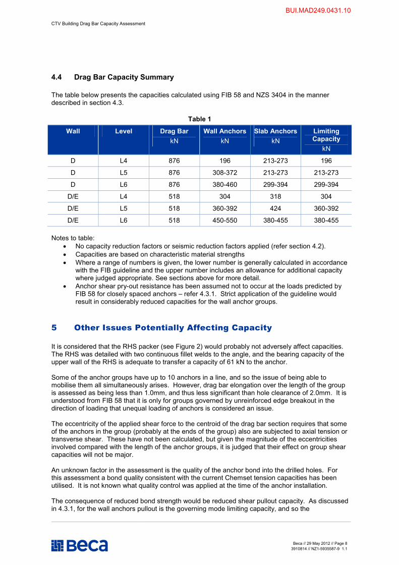
4.4 Drag Bar Capacity Summary The table below presents the capacities calculated using FIB 58 and NZS 3404 in the manner described in section 4.3.
Table 1
Wall Level Drag Bar kN
Wall Anchors kN
Slab Anchors kN
Limiting Capacity
kN
D L4 876 196 213-273 196
D L5 876 308-372 213-273 213-273
D L6 876 380-460 299-394 299-394
D/E L4 518 304 318 304
D/E L5 518 360-392 424 360-392
D/E L6 518 450-550 380-455 380-455 Notes to table:
• No capacity reduction factors or seismic reduction factors applied (refer section 4.2). • Capacities are based on characteristic material strengths • Where a range of numbers is given, the lower number is generally calculated in accordance
with the FIB guideline and the upper number includes an allowance for additional capacity where judged appropriate. See sections above for more detail.
• Anchor shear pry-out resistance has been assumed not to occur at the loads predicted by FIB 58 for closely spaced anchors – refer 4.3.1. Strict application of the guideline would result in considerably reduced capacities for the wall anchor groups.
5 Other Issues Potentially Affecting Capacity It is considered that the RHS packer (see Figure 2) would probably not adversely affect capacities. The RHS was detailed with two continuous fillet welds to the angle, and the bearing capacity of the upper wall of the RHS is adequate to transfer a capacity of 61 kN to the anchor. Some of the anchor groups have up to 10 anchors in a line, and so the issue of being able to mobilise them all simultaneously arises. However, drag bar elongation over the length of the group is assessed as being less than 1.0mm, and thus less significant than hole clearance of 2.0mm. It is understood from FIB 58 that it is only for groups governed by unreinforced edge breakout in the direction of loading that unequal loading of anchors is considered an issue. The eccentricity of the applied shear force to the centroid of the drag bar section requires that some of the anchors in the group (probably at the ends of the group) also are subjected to axial tension or transverse shear. These have not been calculated, but given the magnitude of the eccentricities involved compared with the length of the anchor groups, it is judged that their effect on group shear capacities will not be major. An unknown factor in the assessment is the quality of the anchor bond into the drilled holes. For this assessment a bond quality consistent with the current Chemset tension capacities has been utilised. It is not known what quality control was applied at the time of the anchor installation. The consequence of reduced bond strength would be reduced shear pullout capacity. As discussed in 4.3.1, for the wall anchors pullout is the governing mode limiting capacity, and so the
BUI.MAD249.0431.10
CTV Building Drag Bar Capacity Assessment
Beca // 29 May 2012 // Page 9
3910814 // NZ1-5935587-9 1.1
consequence of a lesser bond would be reduced anchor capacities translating into reduced capacities for several of the drag bars. It is known that the bond strength of bonded anchors can decrease with time, and FIB 58 discusses this issue. However it appears, based on a brief reading that this may be in the context of sustained loading only.
6 Closing Comments Several assumptions have been made in the assessment that should be noted, including the following:
1. That the FIB shear pry-out capacities for closely spaced anchors are too conservative. Ideally, this assumption should be validated by communication with experts in the field, but that has not been possible within the scope and timeframe in which this report has been prepared.
2. That the structural elements into which the anchors are installed are not themselves at the ultimate limit state when the anchor loads are applied. It is understood that post-earthquake inspection of the walls indicates little ULS behaviour, and so this seems reasonable in this case. The slab elements would have little demands upon them other than those exerted by the anchors and so this seems reasonable in this case also.
3. An assumed anchor bond strength, which in turn assumes good quality installation and no long term deterioration. Some of the photographs viewed indicate that during the final stages of collapse with the slab rotating downwards, but held up by the drag bars, some anchors pulled out of the slab by bond failure rather than cone failure. Our calculations with an assumed bond strength indicate that cone failure should have preceded pullout. This may indicate a lower than assumed bond strength. However, this would have been more of an issue for the wall anchors than the slab anchors – and it is understood that no wall anchor failures were observed.
The limiting capacities quoted in Table 1 are in all cases governed or very close to being governed by capacities calculated for the slab anchor groups, with edge breakout predicted and taken into account in the capacities. They are static load capacities based on characteristic strengths without the usual capacity reduction factors that allow for workmanship, variability in material strengths and approximations inherent in capacity calculations. It should be noted that if they were to be used for seismic design purposes FIB 58 would require them to be scaled down considerably, in some cases to approximately 50% of the values quoted. For capacity assessment purposes it is common to use probable material strengths rather than characteristic strengths which would increase capacities. However the effect of doing so would not outweigh the reduction factors described above. Thus while the figures in Table 1 can be viewed as a best estimate of static capacity assuming characteristic material strengths, they should not be viewed as a lower bound on the actual tension capacity of the CTV Drag Bars under seismic loading. The Ramset Resource Book gives stud shear (steel failure) capacities 25% higher than those from FIB 58, and edge breakout values are up to 50% higher. The basis of the Ramset capacities is not stated and we have not explored the reason for the differences, but this may indicate that FIB 58 is conservative. Thus the values in Table 1 should also not be viewed as an upper bound to actual seismic capacities. The assessment exercise has highlighted the uncertainties involved in assessing the capacity of large groups of bonded anchors close to the edge of structural concrete elements. Improved
BUI.MAD249.0431.11
CTV Building Drag Bar Capacity Assessment
Beca // 29 May 2012 // Page 10 3910814 // NZ1-5935587-9 1.1
assessments may be able to be achieved by access to testing data or experts in anchor group assessment. Alternatively, physical testing could be employed if greater certainty was desired.
BUI.MAD249.0431.12

Appendix A - Figures
BUI.MAD249.0431.13
BUI.MAD249.0431.14
rld1
Typewritten Text
rld1
Typewritten Text
rld1
Typewritten Text
CTV Building Figure 1
rld1
Typewritten Text
rld1
Typewritten Text
rld1
Typewritten Text
rld1
Typewritten Text
rld1
Typewritten Text
rld1
Typewritten Text
rld1
Typewritten Text
rld1
Typewritten Text
rld1
Typewritten Text
rld1
Typewritten Text
rld1
Typewritten Text
rld1
Typewritten Text
rld1
Typewritten Text
rld1
Typewritten Text
rld1
Typewritten Text

BUI.MAD249.0431.15
rld1
Typewritten Text
CTV Building Figure 2
rld1
Typewritten Text
rld1
Typewritten Text
BUI.MAD249.0431.16
rld1
Typewritten Text
rld1
Typewritten Text
CTV Building Figure 3

BUI.MAD249.0431.17
rld1
Typewritten Text
CTV Building Figure 4

BUI.MAD249.0431.18
rld1
Typewritten Text
CTV Building Figure 5
BUI.MAD249.0431.19
rld1
Typewritten Text
CTV Building Figure 6
rld1
Typewritten Text
rld1
Typewritten Text
rld1
Typewritten Text
BUI.MAD249.0431.20
rld1
Typewritten Text
rld1
Typewritten Text
CTV Building Figure 7
BUI.MAD249.0431.21
rld1
Typewritten Text
CTV Building Figure 8

BUI.MAD249.0431.22
rld1
Typewritten Text
rld1
Typewritten Text
CTV Building Figure 9
rld1
Typewritten Text
rld1
Typewritten Text
rld1
Typewritten Text
rld1
Typewritten Text
rld1
Typewritten Text
rld1
Typewritten Text
rld1
Typewritten Text
Related Documents