NYU WIRELESS The World's First Academic Research Center Combining Wireless, Computing, and Medical Applications T.S. Rappaport 2014 NYU WIRELESS NYU Polytechnic School of Engineering, Brooklyn, New York, 11201 CEATEC JAPAN 2014 8 October 2014 10:00 – 10:30 3GPP-Style Statistical Channel Models and Directional Beamforming Models for Outdoor Millimeter-Wave Wireless Communications Mathew K. Samimi, Shu Sun, George N. Wong, and T. S. Rappaport [email protected], [email protected], [email protected], [email protected]

Welcome message from author
This document is posted to help you gain knowledge. Please leave a comment to let me know what you think about it! Share it to your friends and learn new things together.
Transcript
NYU WIRELESS The World's First Academic Research Center Combining
Wireless, Computing, and Medical Applications
T.S. Rappaport 2014
NYU WIRELESS
NYU Polytechnic School of Engineering, Brooklyn, New York, 11201
CEATEC JAPAN 2014
8 October 2014
10:00 – 10:30
3GPP-Style Statistical Channel Models and Directional Beamforming Models for Outdoor Millimeter-Wave
Wireless Communications
Mathew K. Samimi, Shu Sun, George N. Wong, and T. S. Rappaport
[email protected], [email protected], [email protected], [email protected]

2
• 28 GHz and 73 GHz Mobile Measurements and Equipment
(Summer 2012, Summer 2013, Ongoing)
• Omnidirectional Path Loss Models in LOS and NLOS
• 28 GHz Statistical Channel Models in LOS and NLOS
• Beamcombining Models at 28 GHz and 73 GHz
• Upgrades to Channel Sounder and Upcoming Measurements
• Joining the Industry Affiliates Program at NYU WIRELESS
Agenda

3
The Wireless Spectrum Today
AM Radio
FM Radio
Wi-Fi
3G/4G LTE
Cellular
TV Broadcast
28 GHz – LMDS
(5G Cellular)
38 GHz
(5G Cellular)
Active CMOS IC
Research
73 GHz
Backhaul 60 GHz
Spectrum
WiGig (802.11 ad)
T. S. Rappaport, R. W. Heath, Jr., R. C. Daniels, and J. N. Murdock, Millimeter Wave
Wireless Communications. Pearson/Prentice Hall, 2015.

4
28 GHz Propagation Measurement
Campaign in Manhattan – Summer 2012
28 GHz Cellular Measurements Locations in Manhattan
near NYU campus
COLES
KAUFMAN
• 3 BS Locations (yellow stars):
Kaufman Center – 17m
Coles Sports Center – 7m (x2)
• 25 RX Locations (green dots,
purple squares):
TR Distances 30 m – 500 m
• BS to MS measurements
• 3 TX Sites: 3 AOD, 1 sweep
• 400 Mcps Broadband Sliding
Correlator Channel Sounder
T. S. Rappaport, S. Sun, R. Mayzus, H. Zhao, Y. Azar, K. Wang, G. N. Wong, J. K.
Schulz, M. Samimi, F. Gutierrez, “Millimeter Wave Mobile Communications for 5G
Cellular: It Will Work!,” IEEE Access, vol.1, pp.335-349, 2013.
• 25 RX Sites: 3 EL, 9 sweeps

5
28 GHz TX-RX Equipment
Transmitter Receiver

6
PN Code Transmit Probing Signal
211-1 Length PN code Spread Spectrum
7
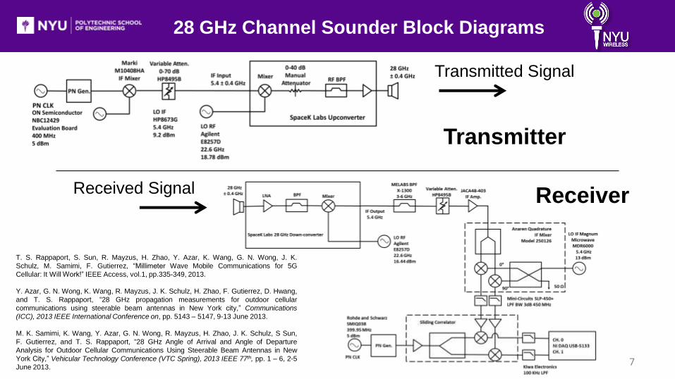
28 GHz Channel Sounder Block Diagrams
Transmitted Signal
Received Signal
Transmitter
Receiver
T. S. Rappaport, S. Sun, R. Mayzus, H. Zhao, Y. Azar, K. Wang, G. N. Wong, J. K.
Schulz, M. Samimi, F. Gutierrez, “Millimeter Wave Mobile Communications for 5G
Cellular: It Will Work!” IEEE Access, vol.1, pp.335-349, 2013.
Y. Azar, G. N. Wong, K. Wang, R. Mayzus, J. K. Schulz, H. Zhao, F. Gutierrez, D. Hwang,
and T. S. Rappaport, “28 GHz propagation measurements for outdoor cellular
communications using steerable beam antennas in New York city,” Communications
(ICC), 2013 IEEE International Conference on, pp. 5143 – 5147, 9-13 June 2013.
M. K. Samimi, K. Wang, Y. Azar, G. N. Wong, R. Mayzus, H. Zhao, J. K. Schulz, S Sun,
F. Gutierrez, and T. S. Rappaport, “28 GHz Angle of Arrival and Angle of Departure
Analysis for Outdoor Cellular Communications Using Steerable Beam Antennas in New
York City,” Vehicular Technology Conference (VTC Spring), 2013 IEEE 77th, pp. 1 – 6, 2-5
June 2013.

8
G. R. MacCartney and T. S. Rappaport, “73 GHz millimeter wave
propagation measurements for outdoor urban mobile and
backhaul communications in New York City," accepted to the
IEEE International Conference on Communications (ICC), 10-14
June 2014.
• 5 TX sites • 27 RX sites
• 74 total TX-RX combinations tested • 36 BS to MS (access) • 38 BS to BS (backhaul). • 2 AOD and 10 AOA sweeps for each
combination with varying elevations between sweeps
• TX sites: • TX-COL1 – 7 m • TX-COL2 – 7 m • TX-KAU – 17 m • TX-KIM1 – 7m • TX-KIM2 – 7m
• RX sites:
• Randomly selected near AC outlets • Located outdoors in walkways
Manhattan Measurements at 73 GHz
(Summer 2012)

9
28 GHz and 73 GHz Sliding Correlator Channel
Sounder Specifications
T. S. Rappaport, et. al., “Millimeter Wave Mobile Communications for 5G Cellular: It Will
Work!” IEEE Access, vol.1, pp.335-349, 2013.
Y. Azar,et. Al., “28 GHz propagation measurements for outdoor cellular communications
using steerable beam antennas in New York city,” Communications (ICC), 2013 IEEE
International Conference on, pp. 5143 – 5147, 9-13 June 2013.
M. K. Samimi, et. al, “28 GHz Angle of Arrival and Angle of Departure Analysis for Outdoor
Cellular Communications Using Steerable Beam Antennas in New York City,” Vehicular
Technology Conference (VTC Spring), 2013 IEEE 77th, pp. 1 – 6, 2-5 June 2013.
Description Value Value
Carrier Frequency 28 GHz 73.5 GHz
Sequence 11th order PN Code (Length = 2047)
Transmitter Chip Rate 400 Mcps
Receiver Chip Rate 399.95 Mcps
RF Bandwidth (First Null) 800 MHz
Slide Factor 8000
Multipath Time Resolution 2.5 ns
Maximum Measurable Path Loss
(5 dB SNR) 178 dB 181 dB
Maximum TX Output 30 dBm 14.6 dBm
TX/RX Antenna Gain 24.5/15 dBi 27 dBi
TX/RX Antenna Azimuth and
Elevation HPBW 10.9°/8.6°, 28.8°/30° 7°

10
73 GHz TX-RX Equipment
TX Hardware
RX Hardware

Creation of an Omnidirectional
Path Loss Model
11
Our work measured path loss at unique pointing angles for directional channel models.
Here, we present the world’s first omnidirectional path loss models suitable for 3GPP/ITU.
[mW] ,,,Prlog10]dBm[]dB[PL 10,,
z y x
zyxw
w
i,jjiji ttrrPt
G. R. MacCartney, Jr., M. K. Samimi, T. S. Rappaport, “Omnidirectional Path Loss Models
in New York City at 28 GHz and 73 GHz,” Personal Indoor and Mobile Radio Communications
(PIMRC), 2014 IEEE 25th International Symposium on, Sept. 2 – 5, 2014.

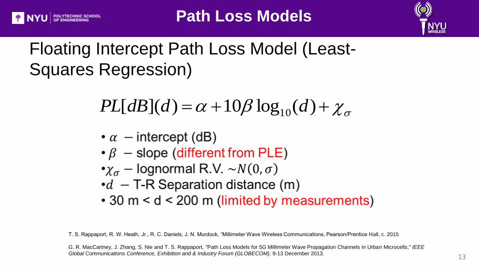
Path Loss Models
12
T. S. Rappaport, Wireless Communications: Principles and Practice, Chapter 4, 2nd Edition, Prentice Hall
Communications Engineering and Emerging Technologies Series, 2002.
Path Loss Models
13
T. S. Rappaport, R. W. Heath, Jr., R. C. Daniels, J. N. Murdock, “Millimeter Wave Wireless Communications, Pearson/Prentice Hall, c. 2015
G. R. MacCartney, J. Zhang, S. Nie and T. S. Rappaport, "Path Loss Models for 5G Millimeter Wave Propagation Channels in Urban Microcells," IEEE
Global Communications Conference, Exhibition and & Industry Forum (GLOBECOM), 9-13 December 2013.
Floating Intercept Path Loss Model (Least-
Squares Regression)
)(log10)]([ 10 dddBPL

28 GHz and 73 GHz Omnidirectional
Path Loss
14
The following models are for 28 GHz access measurements (RX: 1.5 m), and 73 GHz
hybrid measurements (RX: 2 m and 4.06 m) LOS Close-in Reference Model:
NLOS Close-in Reference Model:
NLOS Floating Intercept Model:
G. R. MacCartney, Jr., M. K. Samimi, T. S. Rappaport, “Omnidirectional Path Loss Models
in New York City at 28 GHz and 73 GHz,” Personal Indoor and Mobile Radio Communications
(PIMRC), 2014 IEEE 25th International Symposium on, Sept. 2 – 5, 2014.

15
Current Channel Models: 3GPP and WINNER II
• 1 – 6 GHz RF propagation
• 5 – 100 MHz RF bandwidth
• 20 ns multipath time resolution (best)
• High spatial (angular) resolution
• Inappropriate for describing millimeter-wave
propagation V11.0.0, 3GPP TR 25.996, “Spatial Channel Model for Multipath Input Multiple
Output (MIMO) Simulations,” September 2012

16
NYU Approach to Omni Statistical
Channel Model
a) Superimposed PDPs of two individual PDPs, where each PDP comes from a
different AOA at the same RX.
b) Case 1: Superimposed PDPs at excess delay t = 0 ns.
Case 2: Superimposed PDPs according to absolute time = 0 ns (using ray-tracing
methods).
M. K. Samimi, T. S. Rappaport, “Ultra-Wideband Statistical Channel Model for 28
GHz Millimeter-Wave Urban NLOS Environments,” IEEE Global Communications
Conference, Exhibition & Industry Forum (GLOBECOM), 8 – 12 Dec., 2014.
Multipath from different angles have different propagation
time delays.

17
3-D Ray-Tracing to Synthesize
Omni. PDP
• 4 Strongest AOA’s predicted to synthesize omni PDP
• Minor angle skew does not impact statistical model
M. K. Samimi, T. S. Rappaport, “Characterization of the 28 GHz Millimeter-Wave Dense
Urban Channel for Future 5G Mobile Cellular,” NYU WIRELESS TR 2014-001, June
2014.
Numerical Database:
• Google SketchUp
• 250 m x 250 m
• ~ 5 m accuracy

18
Example of Four Strongest
Measured PDPs to Create Omni. PDP
T1 = 381 ns T2 = 407 ns
T3 = 1433 ns T4 = 1500 ns
M. K. Samimi, T. S. Rappaport, “Characterization of
the 28 GHz Millimeter-Wave Dense Urban Channel
for Future 5G Mobile Cellular,” NYU WIRELESS TR
2014-001, June 2014.

19
28 GHz LOS VS NLOS Spectra
In LOS: Power arriving from all AOA angles (Large RMS Delay Spread)
In NLOS: Power arriving from distinct AOA angles (Smaller RMS Delay Spread)
LOS Polar Plot NLOS Polar Plot
T-R Separation: 54 m T-R Separation: 77 m

20
Omnidirectional Statistical Spatial
Channel Model
Example PDP at one pointing angle T. S. Rappaport, R. W. Heath, Jr., R. C. Daniels, and J. N. Murdock, Millimeter
Wave Wireless Communications. Pearson/Prentice Hall, 2015.
M. K. Samimi, T. S. Rappaport, “Ultra-Wideband Statistical Channel Model for 28
GHz Millimeter-Wave Urban NLOS Environments,” IEEE Global Communications
Conference, Exhibition & Industry Forum (GLOBECOM), 8 – 12 Dec., 2014.

21
Primary Statistics:
Quantities needed to reproduce mmWave omni-PDP:
• Omni-directional path loss model
• # of time clusters
• # of cluster sub-paths in time clusters
• Cluster and cluster sub-path arrival times
• Power in clusters and cluster sub-paths
Secondary Statistics:
Quantities needed to validate simulator:
• Cluster durations
• Inter-cluster void duration
• RMS delay spread
Temporal Channel Modeling
M. K. Samimi, T. S. Rappaport, “Ultra-Wideband Statistical Channel Model for 28
GHz Millimeter-Wave Urban NLOS Environments,” IEEE Global Communications
Conference, Exhibition & Industry Forum (GLOBECOM), 8 – 12 Dec., 2014.

22
Primary Statistics:
Quantities needed to reproduce mmWave PAS (Polar Plot):
• Number of Lobes
• AOAs
• Lobe Azimuth Spreads
• Lobe Segment Powers
Secondary Statistics:
Quantities needed to validate simulator:
• RMS Lobe Azimuth Spread
M. K. Samimi, T. S. Rappaport, “Ultra-Wideband Statistical Channel Model for 28
GHz Millimeter-Wave Urban NLOS Environments,” IEEE Global Communications
Conference, Exhibition & Industry Forum (GLOBECOM), 8 – 12 Dec., 2014.
Spatial Channel Modeling

23
Statistical Modeling for Omnidirectional
mmWave PDPs
Number of clusters and cluster subpaths in NLOS
- Inter-cluster Minimum Void Duration of 2.7 ns
- Cluster Partitioning Scheme Optimized using M. K. Samimi, T. S. Rappaport, “Ultra-Wideband Statistical Channel Model for 28
GHz Millimeter-Wave Urban NLOS Environments,” IEEE Global Communications
Conference, Exhibition & Industry Forum (GLOBECOM), 8 – 12 Dec., 2014. criterion

24
Clusters delays and powers in NLOS
M. K. Samimi, T. S. Rappaport, “Characterization of the 28 GHz Millimeter-Wave Dense
Urban Channel for Future 5G Mobile Cellular,” NYU WIRELESS TR 2014-001, June
2014.
Statistical Modeling for Omnidirectional
mmWave PDPs

25
Clusters subpath delays and powers in NLOS
M. K. Samimi, T. S. Rappaport, “Characterization of the 28 GHz Millimeter-Wave Dense
Urban Channel for Future 5G Mobile Cellular,” NYU WIRELESS TR 2014-001, June
2014.
Statistical Modeling for Omnidirectional
mmWave PDPs

26
Number of Lobes and AOAs in NLOS
• Lobe threshold -20 dB
below maximum PAS segment power • AOA ~ Uniform(0,360)
M. K. Samimi, T. S. Rappaport, “Ultra-Wideband Statistical Channel Model for 28
GHz Millimeter-Wave Urban NLOS Environments,” IEEE Global Communications
Conference, Exhibition & Industry Forum (GLOBECOM), 8 – 12 Dec., 2014.
Statistical Modeling for Omnidirectional
mmWave Power Spectra
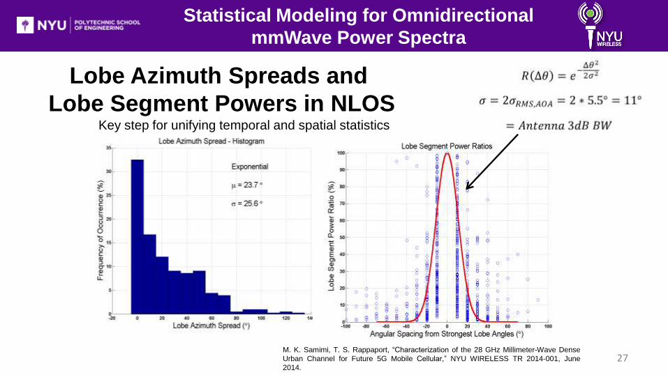
27
Lobe Azimuth Spreads and
Lobe Segment Powers in NLOS Key step for unifying temporal and spatial statistics
M. K. Samimi, T. S. Rappaport, “Characterization of the 28 GHz Millimeter-Wave Dense
Urban Channel for Future 5G Mobile Cellular,” NYU WIRELESS TR 2014-001, June
2014.
Statistical Modeling for Omnidirectional
mmWave Power Spectra

28
10,000 Simulated PDPs VS Synthesized Measured RMS Delay Spreads
in NLOS
Note: more careful noise thresholding
yields lower RMS delay spreads than
published
M. K. Samimi, T. S. Rappaport, “Ultra-Wideband Statistical Channel Model for 28
GHz Millimeter-Wave Urban NLOS Environments,” IEEE Global Communications
Conference, Exhibition & Industry Forum (GLOBECOM), 8 – 12 Dec., 2014.
mmWave Statistical Simulator

29
Statistical Simulator Results
Path Loss Model Error (%)
Omnidirectional (P) (3.4, 9.7 dB) (3.4, 9.8 dB) (0,1.0)
SUMMARY OF THE MEASURED STATISTICS WERE OBTAINED FROM SYNTHESIZED MEASURED 28 GHZ
OMNIDIRECTIONAL WIDEBAND PDPS, AND THE SIMULATED STATISTICS WERE GENERATED FROM 10,000
PDPS AND PAS. (P) AND (S) STAND FOR PRIMARY AND SECONDARY, RESPECTIVELY.
Path Loss Model in NLOS:
M. K. Samimi, T. S. Rappaport, “Ultra-Wideband Statistical Channel Model for 28
GHz Millimeter-Wave Urban NLOS Environments,” IEEE Global Communications
Conference, Exhibition & Industry Forum (GLOBECOM), 8 – 12 Dec., 2014.

30
Type of
Statistic Quantity
Error (%)
Temporal
Number of Clusters
(P)
Poisson
(3.4, 2.1) (3.2, 2.1) (5.9, 0)
Number of Cluster
Sub-Paths (P)
Exponential
(2.1, 1.6) (2.2, 1.7) (4.7, 6.3)
Cluster Excess Time
Delay (ns) (P)
Exponential
(66.3, 68.0) (71.8, 62.1) (8.3, 8.7)
Cluster Sub-path
Excess Time Delay
(ns) (P)
Exponential
(8.1, 8.8) (8.6, 8.0) (6.2, 9.1)
RMS Delay Spread
(ns) (S)
Exponential
(13.4, 11.5) (12.9, 11.3) (3.7, 1.7)
Cluster RMS Delay
Spread (ns) (S)
Exponential
(2.0, 2.0) (2.4, 1.7) (20.0, 15.0)
Cluster Duration (ns)
(S)
Exponential
(8.9, 8.7) (10.7, 8.4) (20.2, 3.5)
Inter-cluster Void
Duration (ns) (S)
Exponential
(16.8, 17.2) (21.5, 15.9) (28.0, 7.5)
Temporal Statistics in NLOS: All primary statistics within 10% error
SUMMARY OF THE MEASURED STATISTICS WERE OBTAINED FROM TIME-SYNTHESIZED MEASURED 28 GHZ OMNIDIRECTIONAL WIDEBAND PDPS, AND
THE SIMULATED STATISTICS WERE GENERATED FROM 10,000 PDPS AND PAS. (P) AND (S) STAND FOR PRIMARY AND SECONDARY, RESPECTIVELY.
M. K. Samimi, T. S.
Rappaport, “Ultra-Wideband
Statistical Channel Model for
28 GHz Millimeter-Wave
Urban NLOS Environments,”
IEEE Global Communications
Conference, Exhibition &
Industry Forum
(GLOBECOM), 8 – 12 Dec.,
2014.
T. S. Rappaport, R. W.
Heath, Jr., R. C.
Daniels, and J. N.
Murdock, Millimeter
Wave Wireless
Communications.
Pearson/Prentice Hall,
2015.
Statistical Simulator Results

31
Spatial Statistics in NLOS: SUMMARY OF THE MEASURED STATISTICS WERE OBTAINED FROM SYNTHESIZED MEASURED 28 GHZ
OMNIDIRECTIONAL WIDEBAND PDPS, AND THE SIMULATED STATISTICS WERE GENERATED FROM 10,000
PDPS AND PAS. (P) AND (S) STAND FOR PRIMARY AND SECONDARY, RESPECTIVELY.
M. K. Samimi, T. S.
Rappaport, “Ultra-Wideband
Statistical Channel Model for
28 GHz Millimeter-Wave
Urban NLOS Environments,”
IEEE Global Communications
Conference, Exhibition &
Industry Forum
(GLOBECOM), 8 – 12 Dec.,
2014.
T. S. Rappaport, R. W.
Heath, Jr., R. C.
Daniels, and J. N.
Murdock, Millimeter
Wave Wireless
Communications.
Pearson/Prentice Hall,
2015.
Statistical Simulator Results
Type of Statistic Quantity AOA/AOD Measured (μ,𝜎) Simulated (μ,𝜎) Error (%)
Spatial
(NLOS)
Number of Lobes (P)
AOA Poisson
(2.4, 1.3) (2.3, 1.1) (4.2, 15.4)
AOD Poisson
(2.0, 1.3) (1.8, 0.9) (10.0, 30.0)
Mean Pointing AOA Uniform(0,360) Uniform(0,360) 0
Angle (°) (P) AOD Uniform(0,360) Uniform(0,360) 0
Lobe Azimuth
Spread (°) (P)
AOA Normal
(34.8, 25.7) (34.6, 27.8) (0.2, 9.0)
AOD Normal
(42.5, 25.2) (43.6, 26.1) (2.6, 3.6)
RMS Lobe Azimuth
Spread (°) (S)
AOA Exponential
(6.1, 5.8) (8.3, 6.8) (36.0, 17.0)
AOD Normal
(7.7, 5.3) (8.0, 7.0) (4.0, 32.0)

Typical Polar Plots for TX at 28 GHz (Simulated)
32
TX LOS AOD for 28 GHz TX NLOS AOD at 28 GHz
“MIMO for Millimeter Wave Wireless Communications: Beamforming, Spatial Multiplexing, or Both?” S. Sun, et. al., IEEE Comm. Mag., Dec. 2014, to appear.
33
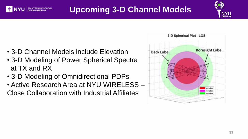
Upcoming 3-D Channel Models
• 3-D Channel Models include Elevation
• 3-D Modeling of Power Spherical Spectra
at TX and RX
• 3-D Modeling of Omnidirectional PDPs
• Active Research Area at NYU WIRELESS –
Close Collaboration with Industrial Affiliates

Opportunity for Beamforming
and Beam Combining
Typical polar plot showing
received power at different
angles of arrival (AOAs)
Signals were received at 26
out of 45 RX azimuth angles
Signals coming from a
myriad of beams can be
combined to enhance the
received signal level
34
Millimeter Wave Multi-beam Antenna Combining for 5G Cellular Link Improvement in New York City
S. Sun, G. R. MacCartney, M. K. Samimi, S. Nie, and T. S. Rappaport, “Millimeter Wave Multi-
beam Antenna Combining for 5G Cellular Link Improvement in New York City,” 2014 IEEE
International Conference on Communications (ICC), Sydney, Australia, June 10-14, 2014.

10/3/2014 35
Beam Combining Procedure
S. Sun, G. R. MacCartney, M. K. Samimi, S. Nie, and T. S. Rappaport, “Millimeter Wave Multi-
beam Antenna Combining for 5G Cellular Link Improvement in New York City,” 2014 IEEE
International Conference on Communications (ICC), Sydney, Australia, June 10-14, 2014.

Beam Combining Results at 28 GHz
“NC”: Non-coherent Combining
“C”: Coherent Combining
Beam combining can significantly
improve path loss exponents (PLEs)
The performance of coherent combining is
superior to that of non-coherent combining
36
S. Sun, G. R. MacCartney, M. K. Samimi, S. Nie, and T. S.
Rappaport, “Millimeter Wave Multi-beam Antenna Combining
for 5G Cellular Link Improvement in New York City,” 2014 IEEE
International Conference on Communications (ICC), Sydney,
Australia, June 10-14, 2014.

Frequency
(GHz)
TX, RX
Antenna
Gains (dBi)
TX
Height
(m)
RX Height
(m)
# of
Combined
Beams
Coherent Noncoherent
Path Loss
Exponent
Shadow
Factor (dB)
Path Loss
Exponent
Shadow
Factor (dB)
28
24.5,
24.5,
vertically
polarized
7, 17
1.5
Arbitrary
Angle
4.5 10.0 4.5 10.0
1 3.8 9.1 3.8 9.1
2 3.5 9.1 3.7 9.2
3 3.4 9.2 3.6 9.2
4 3.3 9.2 3.6 9.2
73
27,
27,
vertically
polarized
7, 17
2
Arbitrary
Angle
4.6 11.3 4.6 11.3
1 3.7 7.6 3.7 7.6
2 3.5 7.3 3.6 7.4
3 3.3 7.2 3.6 7.3
4 3.2 7.2 3.5 7.3
4.06
Arbitrary
Angle
4.6 10.7 4.6 10.7
1 3.8 8.9 3.8 8.9
2 3.6 8.6 3.7 8.7
3 3.4 8.3 3.7 8.5
4 3.3 8.0 3.6 8.3
Comparison of Path Loss between
28 GHz and 73 GHz
Environment: NLOS
Comparable path
Loss exponents
(PLEs) at 28 GHz
and 73 GHz
37

38
Future Channel Sounding System
Old Sounder New Sounder
• Going from Analog to Digital: Faster Data Rates (Larger Bandwidth Up to 1 Gbps)
• TX-RX Time Synchronization using 1PPS
GPS
• Accurate RX Location Positioning using GPS
• More Compact, More Reliable than PCB and
Analog Components

39
Future mmWave Measurements at NYU
Large scale and small scale propagation measurements:
• Linear track (small scale)
• Different RX locations, separated by a few meters (large scale)

40
Future mmWave Measurements at NYU
Understanding Spatial and Temporal
Correlation: How does the channel
change with small displacements in
position and time? Lobe 1
Lobe 2
dBm dBm
dBm dBm
M. K. Samimi, K. Wang, Y. Azar, G. N. Wong, R. Mayzus, J. K. Schulz, S. Sun,
F. Gutierrez and T. S. Rappaport, "28 GHz Angle of Arrival and Angle of
Departure Analysis for Outdoor Cellular Communications using Steerable Beam
Antennas in New York City," IEEE Vehicular Technology Conference (VTC), 2-5
June 2013

NYU WIRELESS Mission and Expertise
• EXCITING NEW CENTER: 25 faculty and 100 students across NYU
• Solving problems for industry, creating research leaders, and developing fundamental
knowledge and new applications using wireless technologies
• NYU Polytechnic (Electrical and Computer Engineering)
• NYU Courant Institute (Computer Science)
• NYU School of Medicine (Radiology) and world class hospital
• NYU WIRELESS faculty possess a diverse set of knowledge and expertise:
• Communications (DSP, Networks, RF/Microwave, Antennas, Circuits)
• Medical applications (Anesthesiology, EP Cardiology, MRI, Compressed sensing)
• Computing (Graphics, Data mining, Algorithms, Scientific computing)
• Current in-force funding:
• Over $10 Million/annually from NSF, NIH, and Corporate sponsors

Henry Bertoni Radio Channels
POLY
Elza Erkip Communications
POLY
David Goodman Communications
POLY
Mike Knox RF/Microwaves
POLY
Yong Liu Networks
POLY
Ricardo Otazo MRI Imaging
NYUMC
Shivendra Panwar
Cross-layer Design POLY
Ted Rappaport Communications
POLY
Dennis Shasha Algorithms/Dat
a COURANT
Davood Shahrjerdi
Circuits POLY
Yao Wang Image/Video
POLY
NYU WIRELESS Faculty
Peter Voltz DSP/Comms.
POLY
I-Tai Lu Electromagnetics
POLY
Sundeep Rangan Communications
POLY
Ricardo Lattanzi MRI
Optimization NYUMC
Lakshmi Subramanian
Computing COURANT
Christopher Collins
MRI Imaging NYUMC
Jinyang Li Networks COURANT
Dan Sodickson RF/ MRI Design
NYUMC
Ryan Brown RF
Coils/Imaging NYUMC
Justin Cappos Systems Security
POLY
Pei Liu Wireless
Networks POLY
Marc Bloom Anesthesiology
NYUMC
Daniel O'Neill Anesthesiology NYUM
C
NYU WIRELESS Industrial Affiliates
Confidential and proprietary to NYU, do not distribute

44
Conclusion
• mmWave offers new spatial channel
models with high temporal and narrow
spatial resolutions oMultiple temporal clusters per AOA
oMultiple subpath components per temporal cluster (intra-cluster statistics)
oOmnidirectional LOS offers greater RMS delay spreads than NLOS in 2-D
M. K. Samimi, T. S. Rappaport, “Ultra-Wideband Statistical Channel Model for 28
GHz Millimeter-Wave Urban NLOS Environments,” IEEE Global Communications
Conference, Exhibition & Industry Forum (GLOBECOM), 8 – 12 Dec., 2014.
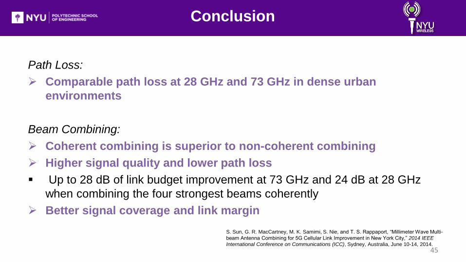
Path Loss:
Comparable path loss at 28 GHz and 73 GHz in dense urban
environments
Beam Combining:
Coherent combining is superior to non-coherent combining
Higher signal quality and lower path loss
Up to 28 dB of link budget improvement at 73 GHz and 24 dB at 28 GHz
when combining the four strongest beams coherently
Better signal coverage and link margin
45
S. Sun, G. R. MacCartney, M. K. Samimi, S. Nie, and T. S. Rappaport, “Millimeter Wave Multi-
beam Antenna Combining for 5G Cellular Link Improvement in New York City,” 2014 IEEE
International Conference on Communications (ICC), Sydney, Australia, June 10-14, 2014.
Conclusion

46
References
[1] S. Rangan, T. S. Rappaport, and E. Erkip, “Millimeter-Wave Cellular Wireless Networks: Potentials and Challenges,” Proceedings of the IEEE, vol.
102, no. 3, pp. 366-385, March 2014.
[2] Y. Azar, G. N. Wong, K. Wang, R. Mayzus, J. K. Schulz, H. Zhao, F. Gutierrez, D. Hwang, T. S. Rappaport, “28 GHz Propagation Measurements for
Outdoor Cellular Communications Using Steerable Beam Antennas in New York City,” 2013 IEEE International Conference on Communications (ICC),
pp.5143-5147, June 2013.
[3] T. S. Rappaport, S. Sun, R. Mayzus, H. Zhao, Y. Azar, K. Wang, G. N. Wong, J. K. Schulz, M. Samimi, F. Gutierrez, “Millimeter Wave Mobile
Communications for 5G Cellular: It Will Work!” IEEE Access, vol.1, pp. 335-349, 2013.
[4] M. K. Samimi, K. Wang, Y. Azar, G. N. Wong, R. Mayzus, J. K. Schulz, S. Sun, F. Gutierrez and T. S. Rappaport, "28 GHz Angle of Arrival and Angle
of Departure Analysis for Outdoor Cellular Communications using Steerable Beam Antennas in New York City," IEEE Vehicular Technology Conference
(VTC), 2-5 June 2013.
[5] H. Zhao, R. Mayzus, S. Sun, M. K. Samimi, Y. Azar, K. Wang, G. N. Wong, F. Gutierrez and T. S. Rappaport, "28 GHz Millimeter Wave Cellular
Communication Measurements for Reflection and Penetration Loss in and around Buildings in New York City," IEEE International Conference on
Communications (ICC), 9-13 June 2013.
[6] S. Nie, G. R. MacCartney, S. Sun and T. S. Rappaport, "72 GHz Millimeter Wave Indoor Measurements for Wireless and Backhaul
Communications," Submitted to the IEEE International Symposium on Personal, Indoor and Mobile Radio Communications (PIMRC), September 2013.
[7] G. R. MacCartney, J. Zhang, S. Nie and T. S. Rappaport, "Path Loss Models for 5G Millimeter Wave Propagation Channels in Urban Microcells,"
IEEE Global Communications Conference, Exhibition and & Industry Forum (GLOBECOM), 9-13 December 2013.
[8] S. Sun and T. S. Rappaport, "Multi-beam Antenna Combining for 28 GHz Cellular Link Improvement in Urban Environments," IEEE Global
Communication Conference, Exhibition & Industry Forum (GLOBECOM), 9-13 December 2013.

47
References
[9] G. R. MacCartney and T. S. Rappaport, "73 GHz Millimeter Wave Propagation Measurements for Outdoor Urban Mobile and Backhaul
Communications in New York City," accepted to the IEEE International Conference on Communications (ICC), 10-14 June 2014.
[10] S. Nie, G. R. MacCartney, S. Sun and T. S. Rappaport, "28 GHz and 73 GHz Signal Outage Study for Millimeter Wave Cellular and
Backhaul Communications," accepted to the IEEE International Conference on Communications (ICC), 10-14 June 2014.
[11] M. K. Samimi, T. S. Rappaport, “Ultra-Wideband Statistical Channel Model for 28 GHz Millimeter-Wave Urban NLOS Environments,”
IEEE Global Communications Conference, Exhibition & Industry Forum (GLOBECOM), 8 – 12 Dec., 2014.
[12] M. K. Samimi, T. S. Rappaport, “Characterization of the 28 GHz Millimeter-Wave Dense Urban Channel for Future 5G Mobile Cellular,”
NYU WIRELESS TR 2014-001, June 2014.
[13] S. Sun and T. S. Rappaport, "Antenna Diversity Combining and Beamforming at Millimeter Wave Frequencies,” NYU WIRELESS
Technical Report TR 2014-002, June 2014.
[14] S. Nie, M. K. Samimi, T. Wu, S. Deng, G. R. MacCartney, Jr., T.S. Rappaport “73 GHz Millimeter-Wave Indoor and Foliage Propagation
Channel Measurements and Results,” NYU WIRELESS Technical Report TR 2014-003, July2014.
[15] S. Sun, G. R. MacCartney, M. K. Samimi, S. Nie, and T. S. Rappaport, “Millimeter Wave Multi-beam Antenna Combining for 5G Cellular
Link Improvement in New York City,” 2014 IEEE International Conference on Communications (ICC), Sydney, Australia, June 10-14, 2014.

ありがとうございました
Arigatoo Gozaimashta!
Questions?
48
Related Documents