PUBLIC J.P. MEUNIER – SAFETY SBC SYSTEM ARCHITECT DAVID LOPEZ, SAFETY SBC SEGMENT & APPLICATION MANAGER OCTOBER 6 TH , 2016 AMF-AUT-T2363 NXP FUNCTIONAL SAFETY METHODOLOGY & CAPABILITIES

Welcome message from author
This document is posted to help you gain knowledge. Please leave a comment to let me know what you think about it! Share it to your friends and learn new things together.
Transcript
PUBLIC
J.P. MEUNIER – SAFETY SBC SYSTEM ARCHITECT
DAVID LOPEZ, SAFETY SBC SEGMENT & APPLICATION MANAGER
OCTOBER 6TH, 2016
AMF-AUT-T2363
NXP FUNCTIONAL SAFETY
METHODOLOGY &
CAPABILITIES
PUBLIC USE1
AGENDA
• Functional Safety Market needs
• Functional Safety is based on Quality
• NXP Safety Architecture
• Certification & Enablement
• Next Generation Safety Architectures to Enable Autonomous Drive
PUBLIC USE2
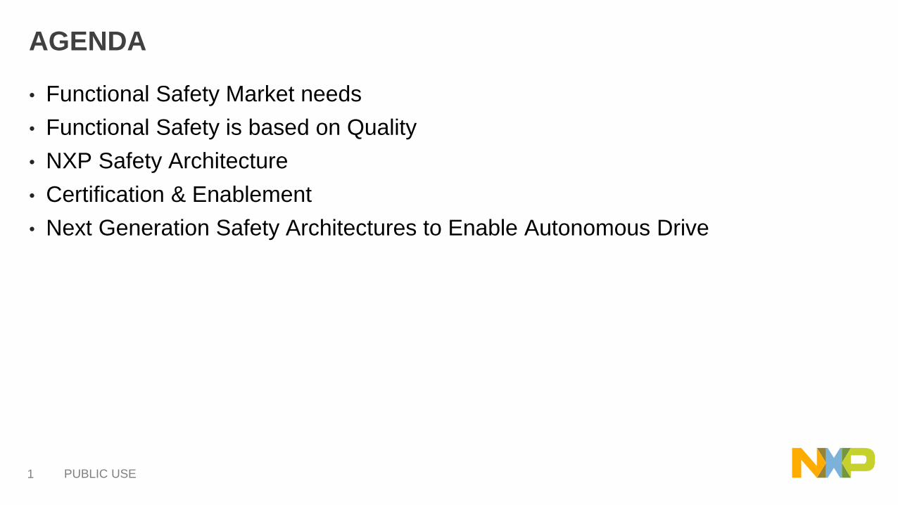
Automotive Market Trends
• Connectivity & Security
− Optimize information flow across the car (from LIN to Ethernet)
− Protect data to avoid hacking
− Simplify network design at OEM level
• Drive Train Electrification
− Green trend : EV / HEV vs combustion to reduce emissions
− 48 V electrical network to improve power efficiency
− ISO26262 Functional Safety growth driver and system availability
• Autonomous & Safe Drive
− Highest automotive MCU/MPUs performance for real time decision
− Increased safety & security level to protect lives (fail operational)
− Driverless to develop social mobility & reduce traffic congestion

PUBLIC USE3
Zero fatalities : Automotive Major Goal
Road Traffic Injuries
Road Traffic Accident will be the 3rd Worldwide
Disability Ajusted Life Years (DALYs)

PUBLIC USE4
Philosophy
Process
PeoplePartners
Products
FUNCTIONAL SAFETY VALUES5P’s Functional Safety Pillars & Differentiation
Philosophy – Culture • « To design systems that work correctly we MUST understand and correct how they can go
wrong » Daniel Saul Goldin, NASA Administrator
• SafeAssure : Corporate commitment to support functional Safety
Products – Value & Differentiation• 1st ISO26262 SBC to fit for ASIL D systems
• Innovative Hardware Monitoring Architecture
ISO26262 certified hardware development process for analog and sensor products
Development rules, processes and tools certified as compliant with ISO 26262 standard part requirements applicable to
semiconductor suppliers
ISO 26262-2:2011 – Safety Management
ISO 26262-5:2011 – Hardware Development
ISO 26262-7:2011 – Production
ISO 26262-8:2011 – Supporting Processes
ISO 26262-9:2011 – Safety Analysis
Process – Discipline • Analog & Sensor ISO26262 Development Process Compliance certified by TÜV-SAAR
People – Know how • Training, Safety Culture & mindset. Expertise on ISO26262 Standard, Hardware architecture
& documentation
Partners – Collaboration • System solution to fit for ASIL (SBC + MCU + Drv)
• System safety Goals (Car OEM)
PUBLIC USE5
SafeAssure™ Program
• NXP simplifies the process of system compliance for automotive and industrial functional safety standards
• Reduces the time and complexity required to develop safety systems that comply with ISO 26262 and IEC 61508 standards
• Supports the most stringent Safety Integrity Levels (SILs)
• Zero defect methodology from design to manufacturing to help ensure our products meet the stringent demands of safety applications
• Functional safety activities address:
− Safety process (FMEA, FTA, FMEDA) integrated into development process
− Safety hardware (safety manual) BIST, ECC, etc
− Safety software (safety manual) Autosar MCAL, OS, core self tests, etc.
− Safety support – training, documentation and tech support
PUBLIC USE6
FUNCTIONAL SAFETY
BASED ON QUALITY

PUBLIC USE7
VEHICLE SAFETY: Zero accidents by human error (ADAS)
SECURITY: Zero accidents by system hacks
FUNCTIONAL SAFETY: Zero accidents by system failures (ISO 26262)
DEVICE RELIABILITY: Zero components failures (robust product)
SECURITY
DEVICE
RELIABILITY
FUNCTIONAL
SAFETY
VEHICLE
SAFETY
ELECTRICAL & AUTONOMOUS VEHICLES
TECHNOLOGY DRIVERS

PUBLIC USE8
Technology
Semiconductor
& Packaging
Design incl.
DFT and
DFM*
Validation,
Characterization,
Qualification
ManufacturingProduction &
TestSupport
Standards: IEC 61508, AEC Q100, ISO TS 16949, ...
Automotive Requirements: Reliabilty, Zero Defects, Supply, Security, ...
The component capability is frozen
after technology, packaging &
product development and impacts
the right slope of the „Bath Tub
Curve“
Quality & Reliability in a Typical Automotive 125degC (Ta) Mission Profile
Note: DFT = Design for Test; DFM = Design for Manufacturability
Quality driven solutions to enable Robust & Safe ICsZVEI work group classified 6 categories for potenial 66 differences
PUBLIC USE9
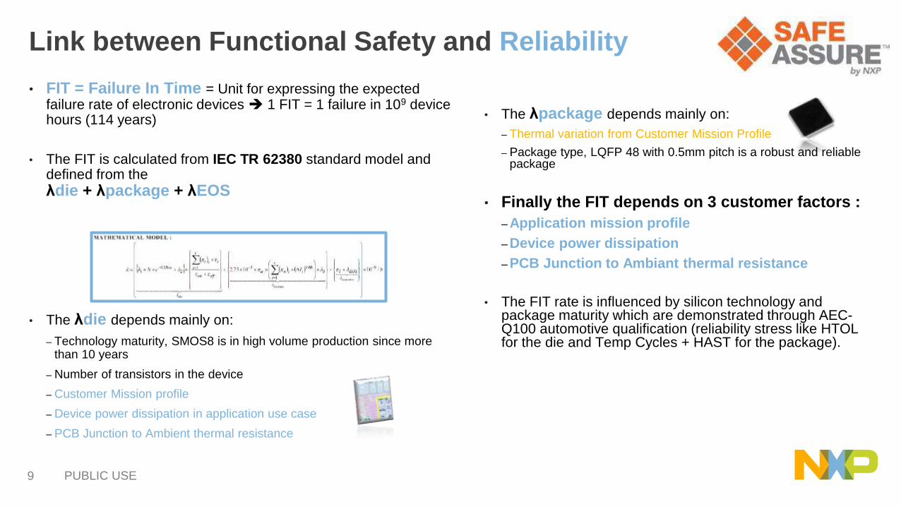
Link between Functional Safety and Reliability
• FIT = Failure In Time = Unit for expressing the expected failure rate of electronic devices 1 FIT = 1 failure in 109 device hours (114 years)
• The FIT is calculated from IEC TR 62380 standard model and defined from the
λdie + λpackage + λEOS
• The λdie depends mainly on:
‒ Technology maturity, SMOS8 is in high volume production since more than 10 years
‒ Number of transistors in the device
‒ Customer Mission profile
‒ Device power dissipation in application use case
‒ PCB Junction to Ambient thermal resistance
• The λpackage depends mainly on:
‒ Thermal variation from Customer Mission Profile
‒ Package type, LQFP 48 with 0.5mm pitch is a robust and reliable package
• Finally the FIT depends on 3 customer factors :
‒ Application mission profile
‒ Device power dissipation
‒ PCB Junction to Ambiant thermal resistance
• The FIT rate is influenced by silicon technology and package maturity which are demonstrated through AEC-Q100 automotive qualification (reliability stress like HTOL for the die and Temp Cycles + HAST for the package).
PUBLIC USE10
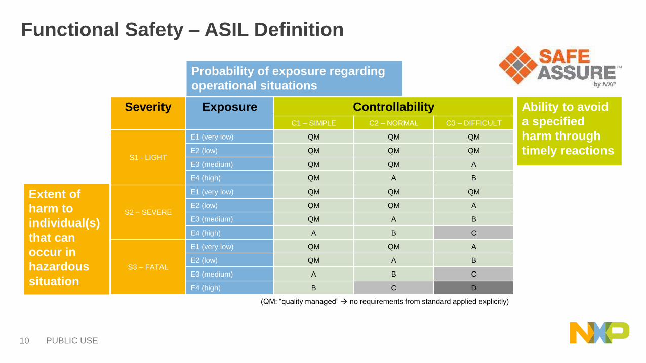
Severity Exposure Controllability
C1 – SIMPLE C2 – NORMAL C3 – DIFFICULT
S1 - LIGHT
E1 (very low) QM QM QM
E2 (low) QM QM QM
E3 (medium) QM QM A
E4 (high) QM A B
S2 – SEVERE
E1 (very low) QM QM QM
E2 (low) QM QM A
E3 (medium) QM A B
E4 (high) A B C
S3 – FATAL
E1 (very low) QM QM A
E2 (low) QM A B
E3 (medium) A B C
E4 (high) B C D
(QM: “quality managed” no requirements from standard applied explicitly)
Extent of
harm to
individual(s)
that can
occur in
hazardous
situation
Ability to avoid
a specified
harm through
timely reactions
Probability of exposure regarding
operational situations
Functional Safety – ASIL Definition

PUBLIC USE11
From Failure Rate to ISO26262 Safety Metrics
FMEDA calculates the safety metrics required by ISO26262
• SPFM: Single point fault − Failure which is immediately violating one of the application safety goal (>99% for ASIL
D)
• LFM: Latent point fault− Failure in the Safety Detection Mechanism (also called monitoring) which could lead to the
violation of the application safety goal in conjunction with a single point fault (>90% for ASIL D)
• PMHF: Probability Metric of Hardware Failure− Residual probability to violate a safety goal (<10-8 for ASIL D)
SPFM
LFM
PMHFSafeAssure — FMEDA
FIT Rate
input of the
FMEDA tool
PUBLIC USE12
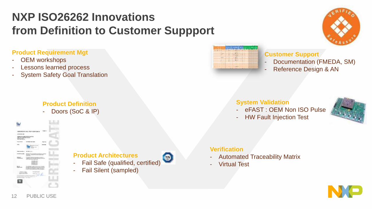
NXP ISO26262 Innovations
from Definition to Customer Suppport
System Validation
- eFAST : OEM Non ISO Pulse
- HW Fault Injection Test
Customer Support
- Documentation (FMEDA, SM)
- Reference Design & AN
Product Architectures
- Fail Safe (qualified, certified)
- Fail Silent (sampled)
Product Requirement Mgt
- OEM workshops
- Lessons learned process
- System Safety Goal Translation
Verification
- Automated Traceability Matrix
- Virtual Test
Product Definition
- Doors (SoC & IP)
PUBLIC USE13
NXP SAFETY
ARCHITECTURES

PUBLIC USE14
ISO26262 ASIL level ASIL D
SPFM (Single Point Failure Metric) > 99%
Fault Management &
ASIL targets in Power Supply
Input
supply Output
Supply
Power Supply
Voltage
supervisor
Safe state
activation
ISO26262 ASIL level ASIL D
LFM (Latent Point Failure Metric) > 90%
Input
supply
Output
supply
Power Supply
Voltage
supervisor
Safe state
activation
LF
LBIST & ABIST
ISO26262 ASIL level ASIL D
PMHF (Probability Metric of Hardware Failure) < 10E-8
Input
supply 1Output
supply
Power Supply
Safe state
activation
LBIST & ABIST
Input
supply 2
BG1
Voltage
supervisor
LF
BG2
SINGLE POINT FAULT LATENT FAULT COMMON CAUSE FAULT

PUBLIC USE15
Independent Fail Safe Machine
Vsup
Clock FS
Vref / BG FS
Ibias FS
Fail Safe
State
Machine
Fail Safe OutputWatchdog
RSTFCCU Error handling
IC Error handling
Analog BIST Logic BIST
Gnd FS
CACHE
PowerPC™
e200Z425 Voltage
Supervisor
Under Voltage
Over Voltage
F/S clock monitoring
F/S output diag
Secured SPI
Clock FS
Vref / BG FS
Ibias FS
Secured SPI
FS0B
VSUPs
Vcore
VPRE 1.5A
2A
• Physically ?
− Has been placed in the die far from the Power (High side
from DC/DC converters)
− Benefit of the SM8MV trench technology
Fail safe machine is completely isolated from other blocks
using isolation trench
ASILD HW READY
Independent Safety monitoring
• Electrically ?
− Fail Safe machine block is :
Supplied by its own voltage and current references
Cadenced by its own 450Khz oscillator
Configured by its dedicated secured SPI
Voltage supervisor provides independent supervision of
power supply for over-voltage & under-voltage detectionIndependent Fail Safe Machine
Vsup
Clock FS
Vref / BG FS
Ibias FS
Fail Safe
State
Machine
Fail Safe OutputWatchdog
RSTFCCU Error handling
IC Error handling
Analog BIST Logic BIST
Gnd FS
CACHE
PowerPC™
e200Z425
Voltage
Supervisor
Under Voltage
Over Voltage
F/S clock monitoring
F/S output diag
Secured SPI
FS1B
PUBLIC USE16
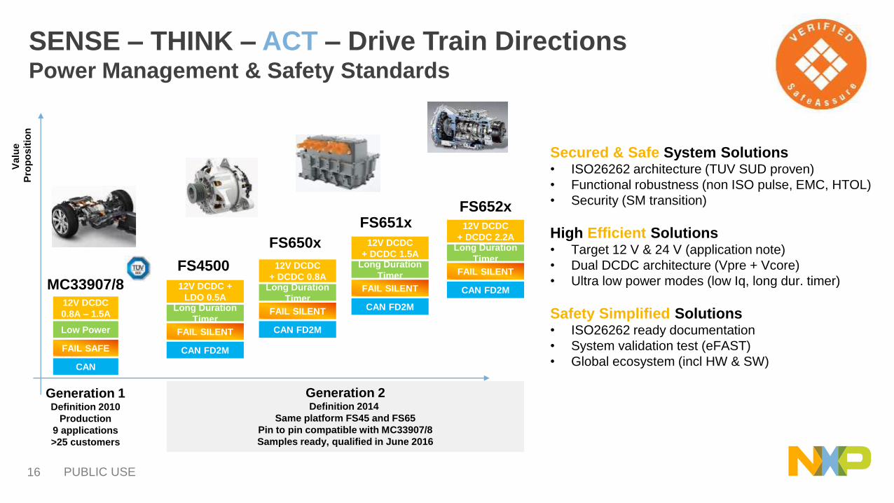
SENSE – THINK – ACT – Drive Train DirectionsPower Management & Safety Standards
CAN
FAIL SAFE
Low Power
12V DCDC
0.8A – 1.5A
CAN FD2M
FAIL SILENT
Long Duration
Timer
12V DCDC
+ DCDC 0.8AMC33907/8
FS650x
Secured & Safe System Solutions • ISO26262 architecture (TUV SUD proven)
• Functional robustness (non ISO pulse, EMC, HTOL)
• Security (SM transition)
High Efficient Solutions• Target 12 V & 24 V (application note)
• Dual DCDC architecture (Vpre + Vcore)
• Ultra low power modes (low Iq, long dur. timer)
Safety Simplified Solutions• ISO26262 ready documentation
• System validation test (eFAST)
• Global ecosystem (incl HW & SW)
Generation 1Definition 2010
Production
9 applications
>25 customers
Generation 2Definition 2014
Same platform FS45 and FS65
Pin to pin compatible with MC33907/8
Samples ready, qualified in June 2016
Va
lue
Pro
po
sit
ion
CAN FD2M
FAIL SILENT
Long Duration
Timer
12V DCDC +
LDO 0.5A
FS4500
CAN FD2M
FAIL SILENT
Long Duration
Timer
12V DCDC
+ DCDC 1.5A
FS651x
CAN FD2M
FAIL SILENT
Long Duration
Timer
12V DCDC
+ DCDC 2.2A
FS652x
PUBLIC USE17
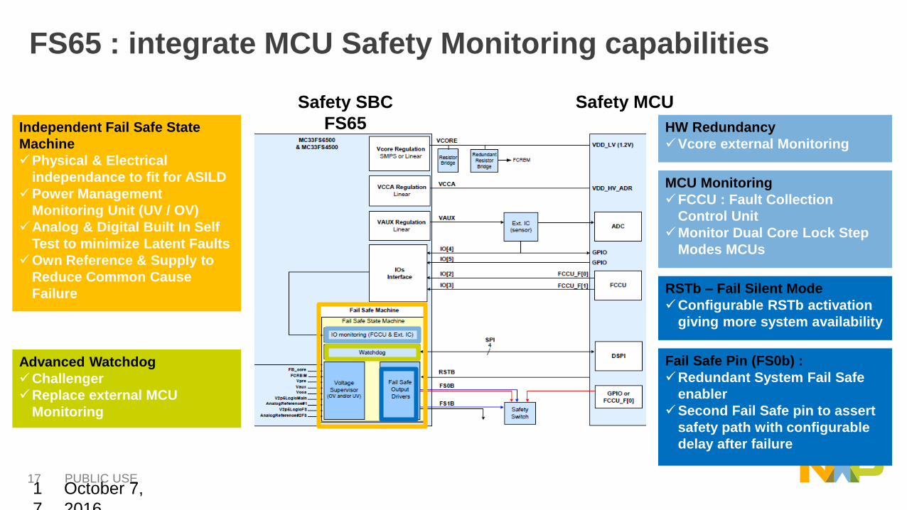
FS65 : integrate MCU Safety Monitoring capabilities
October 7,
2016
1
7.
Independent Fail Safe State
Machine
Physical & Electrical
independance to fit for ASILD
Power Management
Monitoring Unit (UV / OV)
Analog & Digital Built In Self
Test to minimize Latent Faults
Own Reference & Supply to
Reduce Common Cause
Failure
Fail Safe Pin (FS0b) :
Redundant System Fail Safe
enabler
Second Fail Safe pin to assert
safety path with configurable
delay after failure
Advanced Watchdog
Challenger
Replace external MCU
Monitoring
MCU Monitoring
FCCU : Fault Collection
Control Unit
Monitor Dual Core Lock Step
Modes MCUs
RSTb – Fail Silent Mode
Configurable RSTb activation
giving more system availability
HW Redundancy
Vcore external Monitoring
Safety SBC
FS65
Safety MCU
PUBLIC USE18
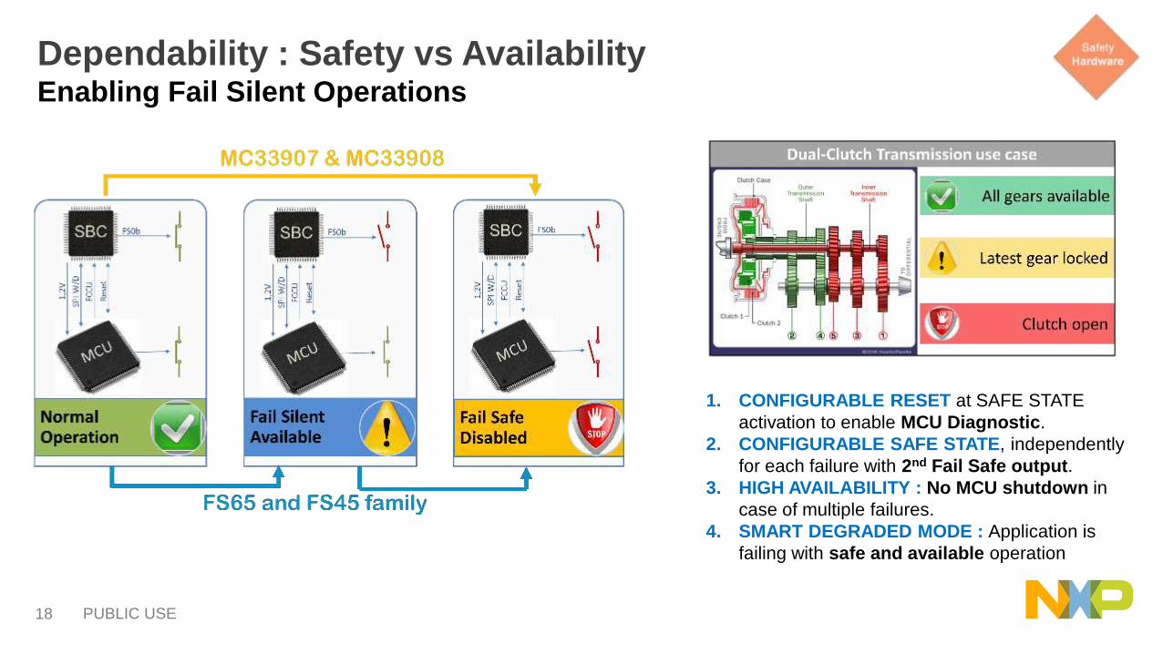
Dependability : Safety vs AvailabilityEnabling Fail Silent Operations
1. CONFIGURABLE RESET at SAFE STATE
activation to enable MCU Diagnostic.
2. CONFIGURABLE SAFE STATE, independently
for each failure with 2nd Fail Safe output.
3. HIGH AVAILABILITY : No MCU shutdown in
case of multiple failures.
4. SMART DEGRADED MODE : Application is
failing with safe and available operation
PUBLIC USE19
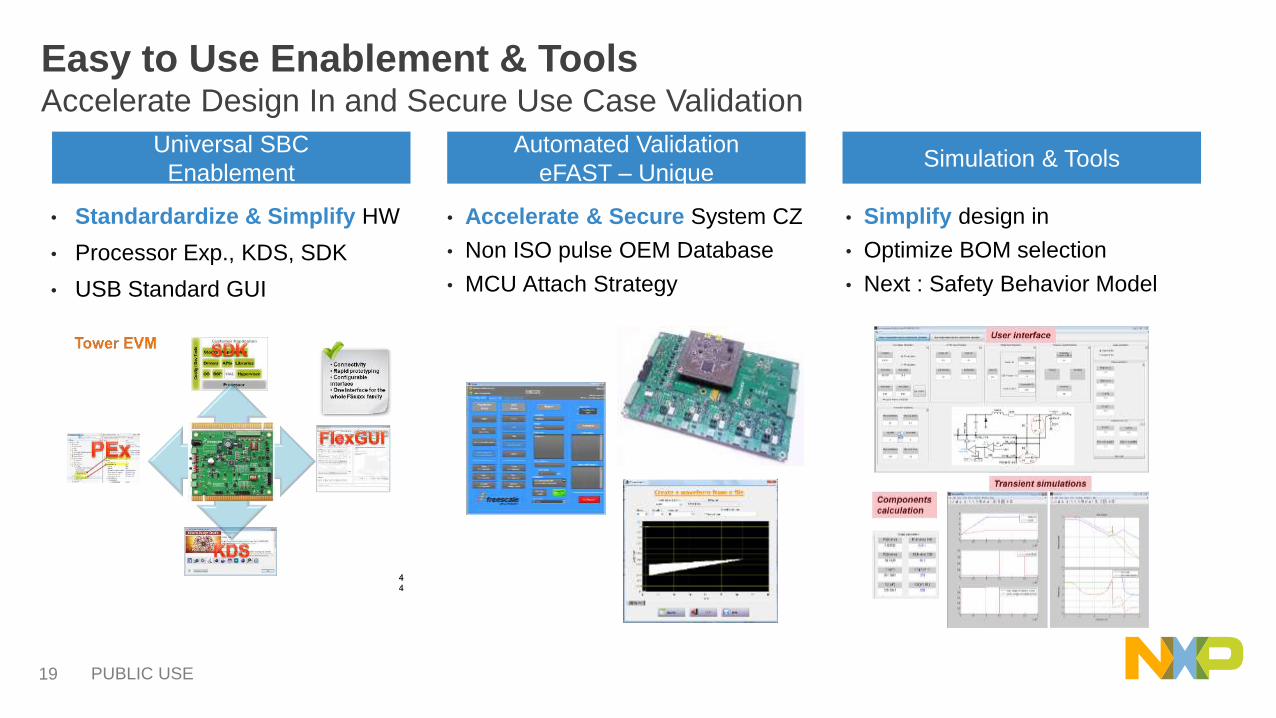
Easy to Use Enablement & ToolsAccelerate Design In and Secure Use Case Validation
• Standardardize & Simplify HW
• Processor Exp., KDS, SDK
• USB Standard GUI
Universal SBC
Enablement
Automated Validation
eFAST – UniqueSimulation & Tools
• Accelerate & Secure System CZ
• Non ISO pulse OEM Database
• MCU Attach Strategy
• Simplify design in
• Optimize BOM selection
• Next : Safety Behavior Model
PUBLIC USE20
SAFETY ARCHITECTURES
TRENDS TO ENABLE
AUTONOMOUS DRIVE

PUBLIC USE21
ADAS SAFETY STRATEGY EVOLUTION
• NXP is leading the industry towards zero accidents
− Safety: zero road accidents caused by drivers (ADAS)
− Functional Safety: zero road accidents caused by system failures (ISO 26262)
− Security: zero road accidents caused by hackers
2016 2018 2020 2030
Fail SafeHigh Failure
Detection
Fail SilentFlexible Failure
Reaction
Fail OperationalIntelligent Failure
Reconfiguration
High DependabilityAdvanced Failure
Prediction
SecuritySafety

PUBLIC USE22
Automated Driving Levels - SAE
• Level 0-2, where the human driver performs part of the dynamic driving task
• Level 3-5, where the automated driving system performs the entire dynamic driving task.
• Needs more performance and towards fail operational safety (Beyond ASIL D as defined by ISO 26262)

Related Documents