NWIS Planning Standards Contingency Planning Criteria Document Number: 21362514

Welcome message from author
This document is posted to help you gain knowledge. Please leave a comment to let me know what you think about it! Share it to your friends and learn new things together.
Transcript

NWIS Planning Standards Contingency Planning Criteria
Document Number: 21362514
Page 2 of 11
Date Created/Last Updated July 2021
Review Frequency 5 years
Next Review Date July 2026
This policy remains in effect, until replaced or updated, notwithstanding expiration of the review date.
Page 3 of 11
TABLE OF CONTENTS
Abbreviations and defined terms ....................................................................................... 4
Application .......................................................................................................................... 5
Transmission System .......................................................................................................... 5
3.1 Transmission N-1 Criteria ............................................................................................ 5
3.2 Transmission N-0 Criteria ............................................................................................ 6
3.3 Substation Planning Criteria ........................................................................................ 7
3.4 Substation N-1 (Firm Capacity) Criterion .................................................................... 7
3.5 Three Transformer Double LV Busbar Substation (Special Case) ............................... 7
3.6 Major Zone Substations .............................................................................................. 8
3.7 Minor Zone Substations .............................................................................................. 8
Distribution Network Utilisation and Contingency Criteria ............................................. 10
4.1 Distribution Interconnector N-1 Criteria ................................................................... 10
4.2 MV Distribution Feeders ........................................................................................... 10
4.3 LV Distribution Feeders ............................................................................................. 11
4.4 Outage Criteria .......................................................................................................... 11

Page 4 of 11
ABBREVIATIONS AND DEFINED TERMS The following abbreviations are used in this document and have the meaning provided in the table below. Table 1.1: Document Abbreviations
Abbreviation Meaning
DTC Distribution Transfer Capacity
HTR Harmonised Technical Rules
HV High Voltage
kV 1000 Volts
LV Low Voltage
MV Medium Voltage
MVA 1000 Volt Amperes
NCR Normal Cyclic Rating
The following defined terms are used in this document and have the meaning provided in the table below. Table 1.2: Document Defined Terms
Defined term Meaning
distribution has the same meaning as “distribution system” in the Act.
{As at 7 April 2020, the definition in section 3 of the Act is — distribution system means electricity infrastructure used, or to be used, for, or in connection with, or to control, the transportation of electricity at nominal voltages of less than 66 kV.”}
Harmonised Technical Rules
as included in the Pilbara Network Rules
Independent System Operator (ISO)
has the meaning given to it in the Pilbara Network Rules
{As at 29 June 2021, the Code defines “ISO” as “means the Pilbara ISO as defined in regulation 14 of the regulations.}
limit advice has the meaning given to it in the Pilbara Network Rules
{As at 29 June 2021, the Code defines “limit advice” as “means the notice given by covered NSP to the ISO under rule 248(2), setting out limit rules, ratings for listed network elements and other constraint information.”.}

Page 5 of 11
Defined term Meaning
network has the same meaning given to ‘network infrastructure facilities’ in the Act.
{As at 07 April 2020, the Act defines ‘network infrastructure facilities’ as―
electricity infrastructure used, or to be used, for the purpose of transporting electricity from generators of electricity to other electricity infrastructure or to end users of electricity; and
includes stand-alone power systems, or storage works, used, or to be used, as an adjunct to electricity infrastructure.}
network service provider (NSP)
has the same meaning given to ‘Pilbara network service provider’ in the Act.
{As at 7 April 2020, the Act defines ‘Pilbara network service provider’ as a person who―
(a) owns, controls or operates a Pilbara network or any part of a Pilbara network; or
(b) proposes to own, control or operate a Pilbara network or any part of a Pilbara network.}
NWIS has the meaning given to it in the Pilbara Network Rules
{As at 29 June 2021, the Code defines “NWIS” as “means the interconnected Pilbara System which includes the Horizon Power coastal network.”}
transmission Means a transmission element as defined in the Pilbara Network Rules.
{As at 29 June 2021, the Pilbara Network Rules defines “transmission element” as “means a network element which operates at transmission voltage, and includes an interconnector regardless of voltage.”}
APPLICATION These planning contingency criteria apply only to the network and not to connection assets. The Network Service Provider must design connection assets in accordance with a User's requirements and the relevant requirements of the Harmonised Technical Rules.
TRANSMISSION SYSTEM Horizon Power will trigger network planning and design processes based on the deterministic contingency criteria detailed in this document.
These contingency criteria apply to the criteria detailed in section 2 of the Harmonised Technical Rules:
The N-1 criterion applies to all transmission lines and major items of plant on Horizon Power’s transmission networks, except those covered by the N-0 criterion under Section 3.2. The N-1 criterion simply means that the consequences of an outage of any one of the N components that make up the transmission system must be examined.
Page 6 of 11
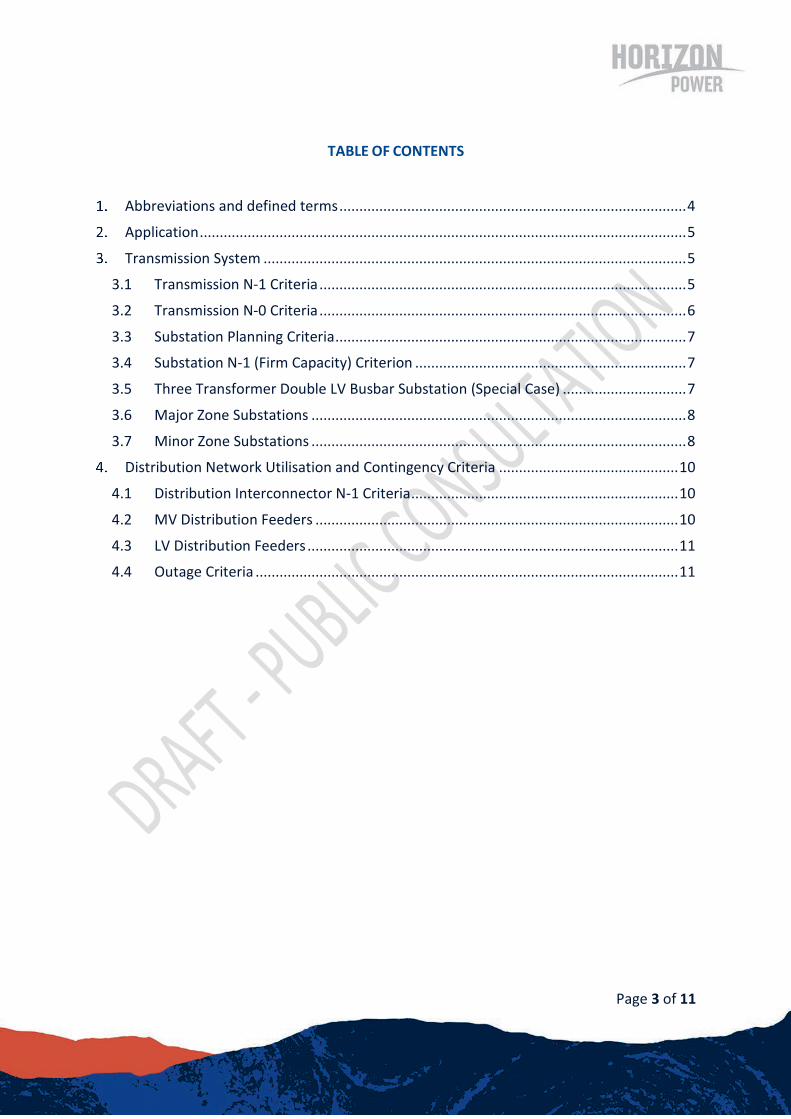
N-1 criterion:
The transmission system must be capable of withstanding the loss of any single component at any load level and for a given generation schedule.
Notes:
1. Under the Pilbara Network Rules, the Horizon Power Pilbara Coastal Network operates within a regime that limits the output of generators to maintain the system within a secure state. A secure state is where system parameters remain within the criteria defined by the Harmonised Technical Rules for the loss of any single system element identified as a credible contingency. Horizon Power is required to provide the Independent System Operator a “limit advice” that details the nature of the required generation limits. Horizon Power develops this limit advice by determining the generation schedules that meet the N-1 criterion.
2. The Horizon Power network planning process adopts a probabilistic approach to quantify the net impact of network constraints, and proposed mitigations, as the basis of network investment (Probabilistic Risk Assessment). The Probabilistic Risk Assessment may include consideration of either the total cost of generation, supply reliability outcomes or safety impacts.
The single component referred to in the above criteria include those listed in the following table: Table 3: Transmission Elements Qualified as Single Contingency (N-1 Criterion)
N-1 Outages
Transmission Line
Transformer
Static VAr Compensators
Circuit Breaker
Capacitor Bank
Substations (see section 3.7)
The N-0 criterion is applied only to minor substations and in some cases, single radial lines supplying minor zone substations (see Section 3.7).
N-0 means that should an element fail or be required out of service for repairs, maintenance or upgrade then supply may be constrained or not met at all until all elements are returned to service.
N-0 criterion:
The system must be capable of meeting the peak load with all elements in service.

Page 7 of 11
Should an element fail or be required out of service for repairs or maintenance then load is not required to be met.
The total capacity of a substation can be limited by any one or more plant items comprising the following main components in a substation:
• Transmission line circuits. • Power transformer circuits.
Horizon Power designs its substations to the Substation N-1 (Firm Capacity) Criterion.
The adequacy of transmission line circuits supplying substations are assessed through load flow studies subject to the N-1 criterion.
The adequacy of power transformer circuits are assessed by comparing the forecasted substation peak load with the substation’s capacity. The amount of load that can be supplied is limited by primary plant equipment ratings and, the amount of distribution transfer capacity (DTC) available.
The N-1 Criterion is used to define a substation’s firm capacity (FC) and is calculated as follows:
• One transformer substation: FC = DTC (1) • Two transformer substation: FC = NCR1 + DTC (2) • Three Transformer substation: FC = NCR1 + NCR2 + DTC (3)
Where,
NCR1 = lowest normal cyclic rating (NCR) of the transformers in the substation;
NCR2 = second lowest NCR of the transformers in the substation;
DTC = available distribution transfer capacity. DTC shall be included in equations (1), (2) and (3) above only if there is a high degree of confidence in its accuracy.
Inclusion of DTC in the firm capacity of a substation introduces the possibility of overloading on remaining transformer circuits following the outage of one transformer circuit. Two overload scenarios can arise depending on the substation’s mode of operation.
In three transformer substations with double LV busbar arrangements where transformers are not operated in parallel, the DTC cannot be included in the substation’s Firm capacity because the third transformer cannot be connected to the LV busbars (i.e. its capacity is not available until at least one of the operational transformers fail).
Transformer load balancing on transformers supplying a double LV busbar arrangement is assumed to be reasonable. It is assumed that as the substation load grows, the load on each
Page 8 of 11
of transformer grows in constant proportion with each other until the heaviest loaded transformer is loaded to a limit of 80% of the smallest transformer’s NCR.
Hence, the Firm capacity is calculated as follows:
FC’ = NCRS1 + NCRS2
where, NCRS1 = smallest1 normal cyclic rating of the transformers in the substation.
NCRS2 = second smallest NCR of the transformers in the substation.
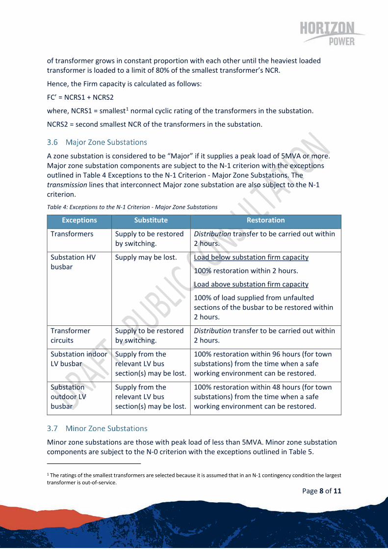
A zone substation is considered to be “Major” if it supplies a peak load of 5MVA or more. Major zone substation components are subject to the N-1 criterion with the exceptions outlined in Table 4 Exceptions to the N-1 Criterion - Major Zone Substations. The transmission lines that interconnect Major zone substation are also subject to the N-1 criterion. Table 4: Exceptions to the N-1 Criterion - Major Zone Substations
Exceptions Substitute Restoration
Transformers Supply to be restored by switching.
Distribution transfer to be carried out within 2 hours.
Substation HV busbar
Supply may be lost. Load below substation firm capacity
100% restoration within 2 hours.
Load above substation firm capacity
100% of load supplied from unfaulted sections of the busbar to be restored within 2 hours.
Transformer circuits
Supply to be restored by switching.
Distribution transfer to be carried out within 2 hours.
Substation indoor LV busbar
Supply from the relevant LV bus section(s) may be lost.
100% restoration within 96 hours (for town substations) from the time when a safe working environment can be restored.
Substation outdoor LV busbar
Supply from the relevant LV bus section(s) may be lost.
100% restoration within 48 hours (for town substations) from the time when a safe working environment can be restored.
Minor zone substations are those with peak load of less than 5MVA. Minor zone substation components are subject to the N-0 criterion with the exceptions outlined in Table 5.
1 The ratings of the smallest transformers are selected because it is assumed that in an N-1 contingency condition the largest transformer is out-of-service.

Page 9 of 11
Exceptions to the N-0 Criterion - Minor Zone Substations. The transmission lines that interconnect Minor Zone substations are also subject to the N-0 reliability criteria with the exceptions outlined in Table 5. Table 5: Exceptions to the N-0 Criterion - Minor Zone Substation
Exceptions Substitute Restoration
Transformers Supply to be restored by switching.
Distribution transfer to be carried out within 2 hours.
For sites with one transformer standby generation and distribution transfer should be used to restore supply.
Transmission lines
Individual justification should be used to provide redundancy or sufficient distribution transfer capacity
Standby local generation may be used to provide immediate restoration.
In the case of substations supplied by single radial lines, line restoration to be provided within 1 to 2 days depending on the extent of damage.
Substation HV busbar
Supply may be lost Load below substation firm capacity
100% restoration within 2 hours.
Load above substation firm capacity
100% of load supplied from unfaulted sections of the busbar to be restored within 2 hours.
Transformer circuits
Supply from the relevant LV bus section may be lost.
Distribution transfer to be carried out within 2 hours.
Page 10 of 11
DISTRIBUTION NETWORK UTILISATION AND CONTINGENCY CRITERIA
A number of Horizon Power systems have dedicated interconnectors between major zone substations or between major zone substations and power stations, which are typically operated at distribution voltages of between 11kV and 33kV (for example the 33kV interconnectors between Broome Power Station and Frederick St substation).
All distribution interconnectors between major zone substations, and between major zone substations and power stations shall be planned in accordance with the Transmission N-1 criterion as outlined in Section 3.1.
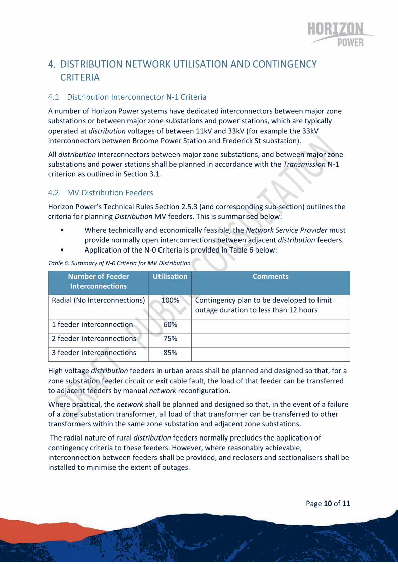
Horizon Power’s Technical Rules Section 2.5.3 (and corresponding sub-section) outlines the criteria for planning Distribution MV feeders. This is summarised below:
• Where technically and economically feasible, the Network Service Provider must provide normally open interconnections between adjacent distribution feeders.
• Application of the N-0 Criteria is provided in Table 6 below: Table 6: Summary of N-0 Criteria for MV Distribution
Number of Feeder Interconnections
Utilisation Comments
Radial (No Interconnections) 100% Contingency plan to be developed to limit outage duration to less than 12 hours
1 feeder interconnection 60%
2 feeder interconnections 75%
3 feeder interconnections 85%
High voltage distribution feeders in urban areas shall be planned and designed so that, for a zone substation feeder circuit or exit cable fault, the load of that feeder can be transferred to adjacent feeders by manual network reconfiguration.
Where practical, the network shall be planned and designed so that, in the event of a failure of a zone substation transformer, all load of that transformer can be transferred to other transformers within the same zone substation and adjacent zone substations.
The radial nature of rural distribution feeders normally precludes the application of contingency criteria to these feeders. However, where reasonably achievable, interconnection between feeders shall be provided, and reclosers and sectionalisers shall be installed to minimise the extent of outages.
Page 11 of 11
Horizon Power’s Technical Rules Section 2.5.4.1 provides the following guidance in planning LV distribution feeders:
“All new low voltage connection points and service mains, and upgrades to existing overhead service mains due to capacity increases, must be underground, even if the service mains are to be connected to an overhead distribution line.”
The outage criteria, in combination with the reliability criteria, set the reliability performance level at which the system must adhere to.
As per Section 2.5.3 of the Horizon Power Technical Rules, the deterministic N-0 criterion is applicable to MV Distribution systems. N-0 means that should an element fail or be required out of service for repairs, maintenance or upgrade then supply may be constrained or not met at all until all elements are returned to service.
Related Documents