In partnership with NetApp Verified Architecture FlexPod Express for VMware vSphere 7.0 with Cisco UCS Mini and NetApp AFF / FAS NVA Deployment Guide Jyh-shing Chen, NetApp January 2021 | NVA-1154-DEPLOY Abstract The FlexPod ® Express for VMware vSphere 7.0 with Cisco UCS Mini and NetApp ® AFF / FAS solution leverages Cisco UCS Mini with B200 M5 blade servers, Cisco UCS 6324 in-chassis Fabric Interconnects, Cisco Nexus 31108PC-V switches, or other compliant switches, and NetApp AFF A220, C190, or the FAS2700 series controller HA pair, which runs NetApp ONTAP ® 9.7 data management software. This NetApp Verified Architecture (NVA) deployment guide provides the detailed steps needed to configure the infrastructure components and to deploy VMware vSphere 7.0 and the associated tools to create a highly reliable and highly available FlexPod Express-based virtual infrastructure.

Welcome message from author
This document is posted to help you gain knowledge. Please leave a comment to let me know what you think about it! Share it to your friends and learn new things together.
Transcript
In partnership with
NetApp Verified Architecture
FlexPod Express for VMware vSphere 7.0
with Cisco UCS Mini and NetApp AFF / FAS
NVA Deployment Guide Jyh-shing Chen, NetApp
January 2021 | NVA-1154-DEPLOY
Abstract
The FlexPod® Express for VMware vSphere 7.0 with Cisco UCS Mini and NetApp® AFF / FAS
solution leverages Cisco UCS Mini with B200 M5 blade servers, Cisco UCS 6324 in-chassis
Fabric Interconnects, Cisco Nexus 31108PC-V switches, or other compliant switches, and
NetApp AFF A220, C190, or the FAS2700 series controller HA pair, which runs NetApp
ONTAP® 9.7 data management software. This NetApp Verified Architecture (NVA)
deployment guide provides the detailed steps needed to configure the infrastructure
components and to deploy VMware vSphere 7.0 and the associated tools to create a highly
reliable and highly available FlexPod Express-based virtual infrastructure.
2 NVA-1154-DEPLOY: FlexPod Express for VMware vSphere 7.0 with Cisco UCS Mini and NetApp AFF/FAS
© 2021 NetApp, Inc. All Rights Reserved.
TABLE OF CONTENTS
Program summary ...................................................................................................................................... 5
Solution overview ....................................................................................................................................... 5
FlexPod Converged Infrastructure program ............................................................................................................5
NetApp Verified Architecture program .....................................................................................................................6
Solution technology .................................................................................................................................................7
Use-case summary ..................................................................................................................................................7
Technology requirements .......................................................................................................................... 8
Hardware requirements ...........................................................................................................................................8
Software requirements ............................................................................................................................................9
Cabling information .................................................................................................................................... 9
Deployment procedures ........................................................................................................................... 11
Cisco Nexus 31108PC-V deployment procedure .................................................................................................. 12
NetApp storage deployment procedure (part 1)..................................................................................................... 19
Cisco UCS Mini deployment procedure ................................................................................................................. 35
NetApp storage deployment configuration (part 2) ................................................................................................ 78
VMware vSphere 7.0 deployment procedure ........................................................................................................ 78
VMware vCenter Server 7.0 deployment procedure .............................................................................................. 91
NetApp Virtual Storage Console 9.7.1 deployment procedure ............................................................................ 102
NetApp SnapCenter Plug-in for VMware vSphere 4.4 deployment procedure .................................................... 111
NetApp Active IQ Unified Manager 9.7P1 deployment procedure ....................................................................... 126
Solution verifications ............................................................................................................................. 138
SAN boot test cases ............................................................................................................................................ 138
Fabric Interconnect test cases ............................................................................................................................. 140
Switch test cases ................................................................................................................................................. 141
Storage test cases ............................................................................................................................................... 144
VMware test cases .............................................................................................................................................. 146
Conclusion .............................................................................................................................................. 148
Appendix .................................................................................................................................................. 148
iSCSI datastore configuration .............................................................................................................................. 148
Where to find additional information .................................................................................................... 150
Version history ........................................................................................................................................ 151
3 NVA-1154-DEPLOY: FlexPod Express for VMware vSphere 7.0 with Cisco UCS Mini and NetApp AFF/FAS
© 2021 NetApp, Inc. All Rights Reserved.
LIST OF FIGURES
Figure 1) FlexPod portfolio. ............................................................................................................................................6
Figure 2) FlexPod Express for VMware vSphere 7 with Cisco UCS Mini and NetApp AFF/FAS architecture. ...............7
Figure 3) Reference validation components and cabling. ............................................................................................. 10
LIST OF TABLES
Table 1) Hardware requirements for the base FlexPod Express with UCS Mini configuration. ......................................8
Table 2) Hardware requirements for the FlexPod Express with UCS Mini using a compliant switches configuration. ...8
Table 3) Software requirements for the base FlexPod Express with UCS Mini implementation. ....................................9
Table 4) Software requirements for a VMware vSphere 7.0 implementation on the FlexPod Express with UCS Mini. ..9
Table 5) Cabling information for Cisco Nexus 31108PC-V switch A. ........................................................................... 10
Table 6) Cabling information for Cisco Nexus 31108PC-V B. ...................................................................................... 10
Table 7) Cabling information for NetApp AFF A220 A. ................................................................................................. 10
Table 8) Cabling information for NetApp AFF A220 B. ................................................................................................. 11
Table 9) Cabling information for Cisco UCS FI-6324 A. ............................................................................................... 11
Table 10) Cabling information for Cisco UCS FI-6324 B. ............................................................................................. 11
Table 11) Required VLANs. .......................................................................................................................................... 12
Table 12) VMware standard vSwitches created for the solution. .................................................................................. 12
Table 13) VMware Infrastructure VMs created for the solution. .................................................................................... 12
Table 14) Nexus 9.3(5) configuration information. ........................................................................................................ 13
Table 15) ONTAP 9.7 installation and configuration information. ................................................................................. 20
Table 16) Information required for NFS configuration. ................................................................................................. 31
Table 17) Information required for iSCSI configuration. ............................................................................................... 33
Table 18) Information required for NFS configuration. ................................................................................................. 34
Table 19) Information required for SVM administrator addition. ................................................................................... 35
Table 20) Information needed to complete the Cisco UCS initial configuration on 6324 A. .......................................... 36
Table 21) Information needed to complete the Cisco UCS initial configuration on 6324 B. .......................................... 37
Table 22) SnapCenter Plug-in for VMware vSphere network port requirements. ....................................................... 112
Table 23) SnapCenter Plug-in for VMware vSphere license requirements. ............................................................... 112
Table 24) SAN boot and OS installation test. ............................................................................................................. 138
Table 25) SAN boot with only one available path test. ............................................................................................... 139
Table 26) SAN boot after service profile migration to a new blade test. ..................................................................... 139
Table 27) Fabric Interconnect reboot test. .................................................................................................................. 140
Table 28) Fabric Interconnect uplink failures test. ...................................................................................................... 140
Table 29) Fabric Interconnect port evacuation test. ................................................................................................... 141
Table 30) Switch minimum Fabric Interconnect uplink traffic test. .............................................................................. 141
Table 31) Switch Fabric Interconnect fabric switching test. ........................................................................................ 142
Table 32) Switch peer virtual port channel traffic test. ................................................................................................ 142
Table 33) Switch reboot test. ...................................................................................................................................... 143

4 NVA-1154-DEPLOY: FlexPod Express for VMware vSphere 7.0 with Cisco UCS Mini and NetApp AFF/FAS
© 2021 NetApp, Inc. All Rights Reserved.
Table 34) Storage link failure test. .............................................................................................................................. 144
Table 35) Storage controller failover test. ................................................................................................................... 144
Table 36) Storage controller reset test. ...................................................................................................................... 145
Table 37) Storage disk failure test. ............................................................................................................................. 145
Table 38) VMware vMotion test. ................................................................................................................................. 146
Table 39) VMware storage vMotion test. .................................................................................................................... 146
Table 40) VMware high availability test. ..................................................................................................................... 147
Table 41) VMware storage vMotion with storage QoS test......................................................................................... 147
5 NVA-1154-DEPLOY: FlexPod Express for VMware vSphere 7.0 with Cisco UCS Mini and NetApp AFF/FAS
© 2021 NetApp, Inc. All Rights Reserved.
Program summary
Industry trends indicate that a vast data center transformation is occurring towards a hybrid cloud
infrastructure with on-premises shared infrastructure, cloud computing, and the connectivity enabled by
data fabric powered by NetApp® to seamlessly provide data where it is needed. In addition, organizations
seek a simple and effective solution for remote and branch offices that uses technology that they are
familiar with in their data center.
FlexPod® Express with Cisco UCS Mini and NetApp AFF/FAS is a predesigned, best practice architecture
that is built on the Cisco Unified Computing System (Cisco UCS), the Cisco Nexus family of switches, and
NetApp storage technologies. The components in a FlexPod Express system are like their FlexPod
Datacenter counterparts, enabling management synergies across the complete IT infrastructure
environment on a smaller scale. FlexPod Datacenter and FlexPod Express are optimal platforms for
virtualization and for bare-metal operating systems and enterprise workloads.
FlexPod Datacenter and FlexPod Express deliver a baseline configuration and have the flexibility to be
sized and optimized to accommodate many different use cases and requirements. Existing FlexPod
Datacenter customers can manage their FlexPod Express system with the same set of tools they are
familiar with. New FlexPod Express customers can easily scale and manage their FlexPod solutions as
they scale and grow their environment.
FlexPod Express is an optimal infrastructure foundation for remote and branch offices and for small to
midsize businesses. It is also an optimal solution for customers who want to provide infrastructure for a
dedicated workload. FlexPod Express provides an easy-to-manage infrastructure that is suitable for
almost any workload.
Solution overview
This FlexPod Express solution is part of the FlexPod Converged Infrastructure program.
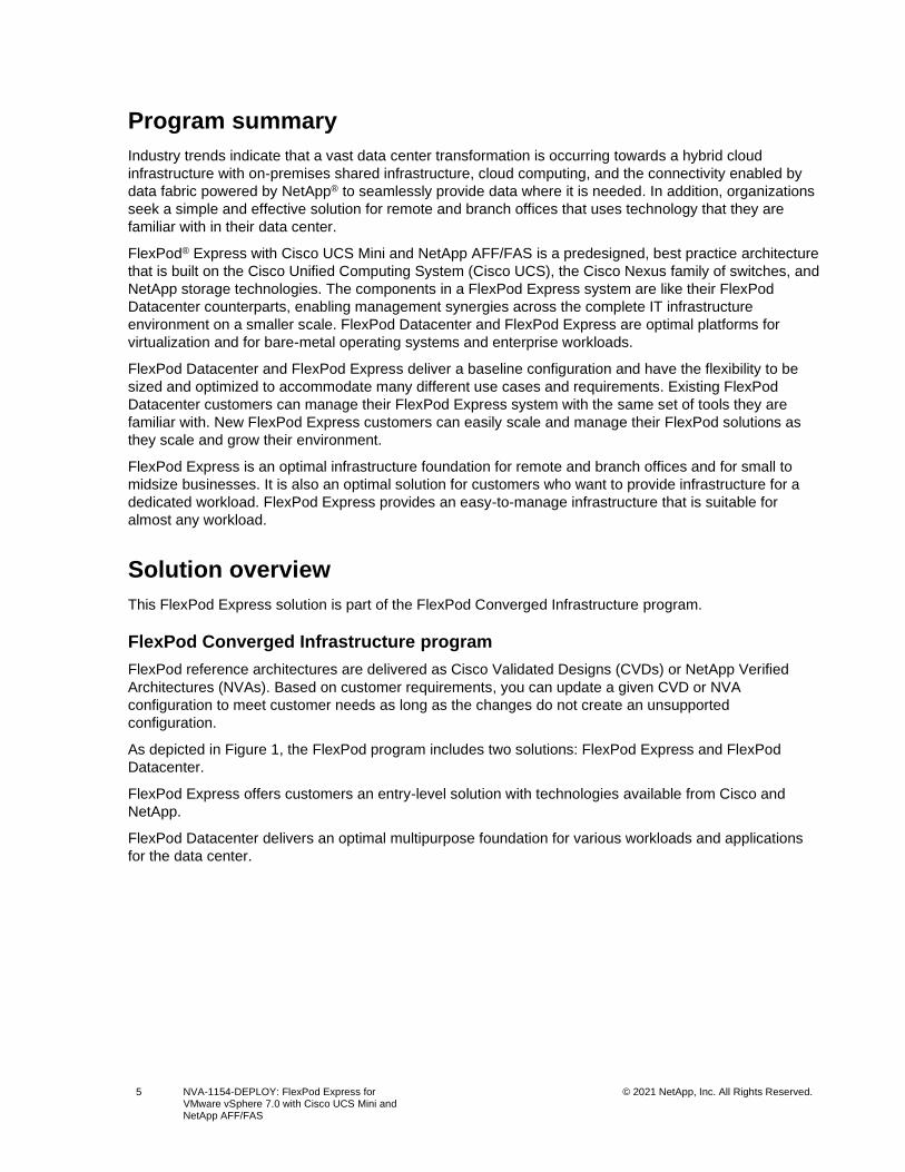
FlexPod Converged Infrastructure program
FlexPod reference architectures are delivered as Cisco Validated Designs (CVDs) or NetApp Verified
Architectures (NVAs). Based on customer requirements, you can update a given CVD or NVA
configuration to meet customer needs as long as the changes do not create an unsupported
configuration.
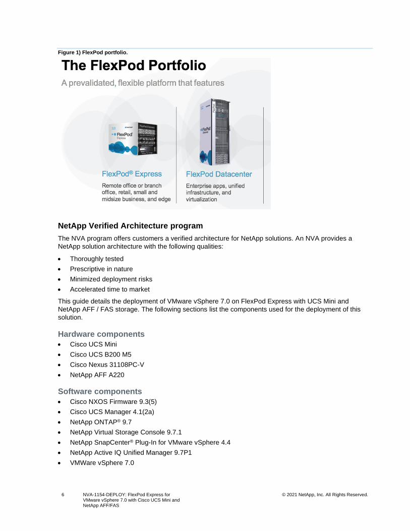
As depicted in Figure 1, the FlexPod program includes two solutions: FlexPod Express and FlexPod
Datacenter.
FlexPod Express offers customers an entry-level solution with technologies available from Cisco and
NetApp.
FlexPod Datacenter delivers an optimal multipurpose foundation for various workloads and applications
for the data center.
6 NVA-1154-DEPLOY: FlexPod Express for VMware vSphere 7.0 with Cisco UCS Mini and NetApp AFF/FAS
© 2021 NetApp, Inc. All Rights Reserved.
Figure 1) FlexPod portfolio.
NetApp Verified Architecture program
The NVA program offers customers a verified architecture for NetApp solutions. An NVA provides a
NetApp solution architecture with the following qualities:
• Thoroughly tested
• Prescriptive in nature
• Minimized deployment risks
• Accelerated time to market
This guide details the deployment of VMware vSphere 7.0 on FlexPod Express with UCS Mini and
NetApp AFF / FAS storage. The following sections list the components used for the deployment of this
solution.
Hardware components
• Cisco UCS Mini
• Cisco UCS B200 M5
• Cisco Nexus 31108PC-V
• NetApp AFF A220
Software components
• Cisco NXOS Firmware 9.3(5)
• Cisco UCS Manager 4.1(2a)
• NetApp ONTAP® 9.7
• NetApp Virtual Storage Console 9.7.1
• NetApp SnapCenter® Plug-In for VMware vSphere 4.4
• NetApp Active IQ Unified Manager 9.7P1
• VMWare vSphere 7.0
7 NVA-1154-DEPLOY: FlexPod Express for VMware vSphere 7.0 with Cisco UCS Mini and NetApp AFF/FAS
© 2021 NetApp, Inc. All Rights Reserved.
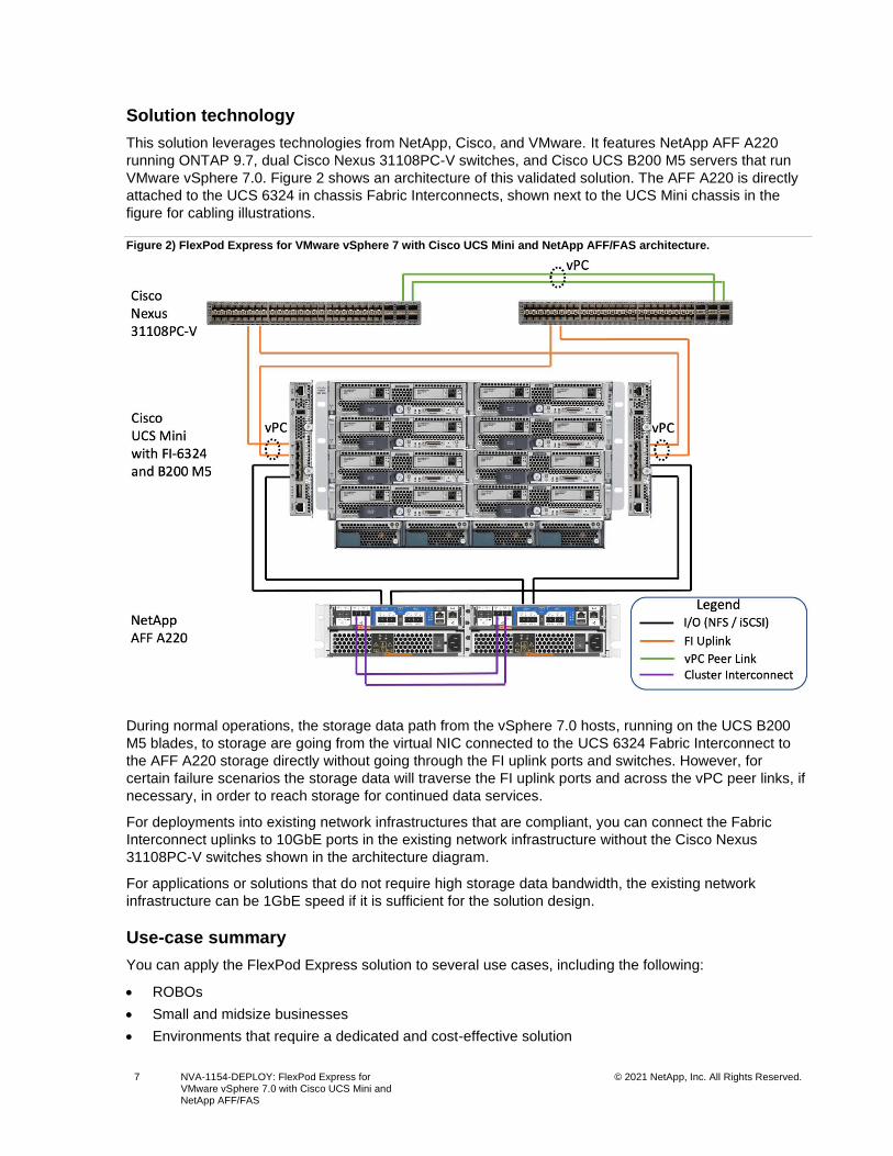
Solution technology
This solution leverages technologies from NetApp, Cisco, and VMware. It features NetApp AFF A220
running ONTAP 9.7, dual Cisco Nexus 31108PC-V switches, and Cisco UCS B200 M5 servers that run
VMware vSphere 7.0. Figure 2 shows an architecture of this validated solution. The AFF A220 is directly
attached to the UCS 6324 in chassis Fabric Interconnects, shown next to the UCS Mini chassis in the
figure for cabling illustrations.
Figure 2) FlexPod Express for VMware vSphere 7 with Cisco UCS Mini and NetApp AFF/FAS architecture.
During normal operations, the storage data path from the vSphere 7.0 hosts, running on the UCS B200
M5 blades, to storage are going from the virtual NIC connected to the UCS 6324 Fabric Interconnect to
the AFF A220 storage directly without going through the FI uplink ports and switches. However, for
certain failure scenarios the storage data will traverse the FI uplink ports and across the vPC peer links, if
necessary, in order to reach storage for continued data services.
For deployments into existing network infrastructures that are compliant, you can connect the Fabric
Interconnect uplinks to 10GbE ports in the existing network infrastructure without the Cisco Nexus
31108PC-V switches shown in the architecture diagram.
For applications or solutions that do not require high storage data bandwidth, the existing network
infrastructure can be 1GbE speed if it is sufficient for the solution design.
Use-case summary
You can apply the FlexPod Express solution to several use cases, including the following:
• ROBOs
• Small and midsize businesses
• Environments that require a dedicated and cost-effective solution
8 NVA-1154-DEPLOY: FlexPod Express for VMware vSphere 7.0 with Cisco UCS Mini and NetApp AFF/FAS
© 2021 NetApp, Inc. All Rights Reserved.
FlexPod Express is ideal for virtualized and mixed workloads.
Technology requirements
A FlexPod Express system requires a combination of hardware and software components. In addition to
the required hardware and software components, you can add additional hardware components to scale
up the solution. Furthermore, you can add additional software and applications to help manage the
solution or provide additional functionalities.
Hardware requirements
Depending on your business requirements, you can use different hypervisors on the same reference
FlexPod Express with UCS Mini hardware configuration.
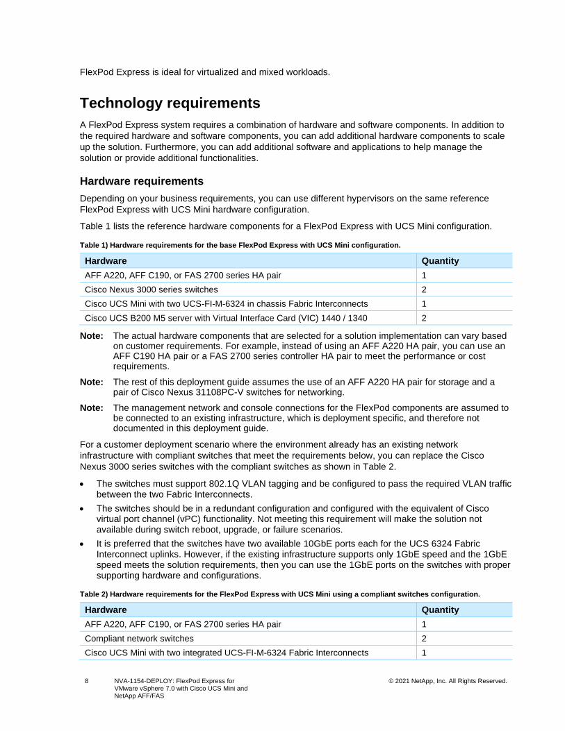
Table 1 lists the reference hardware components for a FlexPod Express with UCS Mini configuration.
Table 1) Hardware requirements for the base FlexPod Express with UCS Mini configuration.
Hardware Quantity
AFF A220, AFF C190, or FAS 2700 series HA pair 1
Cisco Nexus 3000 series switches 2
Cisco UCS Mini with two UCS-FI-M-6324 in chassis Fabric Interconnects 1
Cisco UCS B200 M5 server with Virtual Interface Card (VIC) 1440 / 1340 2
Note: The actual hardware components that are selected for a solution implementation can vary based on customer requirements. For example, instead of using an AFF A220 HA pair, you can use an AFF C190 HA pair or a FAS 2700 series controller HA pair to meet the performance or cost requirements.
Note: The rest of this deployment guide assumes the use of an AFF A220 HA pair for storage and a pair of Cisco Nexus 31108PC-V switches for networking.
Note: The management network and console connections for the FlexPod components are assumed to be connected to an existing infrastructure, which is deployment specific, and therefore not documented in this deployment guide.
For a customer deployment scenario where the environment already has an existing network
infrastructure with compliant switches that meet the requirements below, you can replace the Cisco
Nexus 3000 series switches with the compliant switches as shown in Table 2.
• The switches must support 802.1Q VLAN tagging and be configured to pass the required VLAN traffic between the two Fabric Interconnects.
• The switches should be in a redundant configuration and configured with the equivalent of Cisco virtual port channel (vPC) functionality. Not meeting this requirement will make the solution not available during switch reboot, upgrade, or failure scenarios.
• It is preferred that the switches have two available 10GbE ports each for the UCS 6324 Fabric Interconnect uplinks. However, if the existing infrastructure supports only 1GbE speed and the 1GbE speed meets the solution requirements, then you can use the 1GbE ports on the switches with proper supporting hardware and configurations.
Table 2) Hardware requirements for the FlexPod Express with UCS Mini using a compliant switches configuration.
Hardware Quantity
AFF A220, AFF C190, or FAS 2700 series HA pair 1
Compliant network switches 2
Cisco UCS Mini with two integrated UCS-FI-M-6324 Fabric Interconnects 1
9 NVA-1154-DEPLOY: FlexPod Express for VMware vSphere 7.0 with Cisco UCS Mini and NetApp AFF/FAS
© 2021 NetApp, Inc. All Rights Reserved.
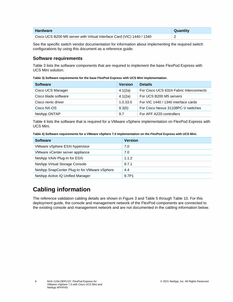
Hardware Quantity
Cisco UCS B200 M5 server with Virtual Interface Card (VIC) 1440 / 1340 2
See the specific switch vendor documentation for information about implementing the required switch
configurations by using this document as a reference guide.
Software requirements
Table 3 lists the software components that are required to implement the base FlexPod Express with
UCS Mini solution.
Table 3) Software requirements for the base FlexPod Express with UCS Mini implementation.
Software Version Details
Cisco UCS Manager 4.1(2a) For Cisco UCS 6324 Fabric Interconnects
Cisco blade software 4.1(2a) For UCS B200 M5 servers
Cisco nenic driver 1.0.33.0 For VIC 1440 / 1340 interface cards
Cisco NX-OS 9.3(5) For Cisco Nexus 31108PC-V switches
NetApp ONTAP 9.7 For AFF A220 controllers
Table 4 lists the software that is required for a VMware vSphere implementation on FlexPod Express with
UCS Mini.
Table 4) Software requirements for a VMware vSphere 7.0 implementation on the FlexPod Express with UCS Mini.
Software Version
VMware vSphere ESXi hypervisor 7.0
VMware vCenter server appliance 7.0
NetApp VAAI Plug-In for ESXi 1.1.2
NetApp Virtual Storage Console 9.7.1
NetApp SnapCenter Plug-In for VMware vSphere 4.4
NetApp Active IQ Unified Manager 9.7P1
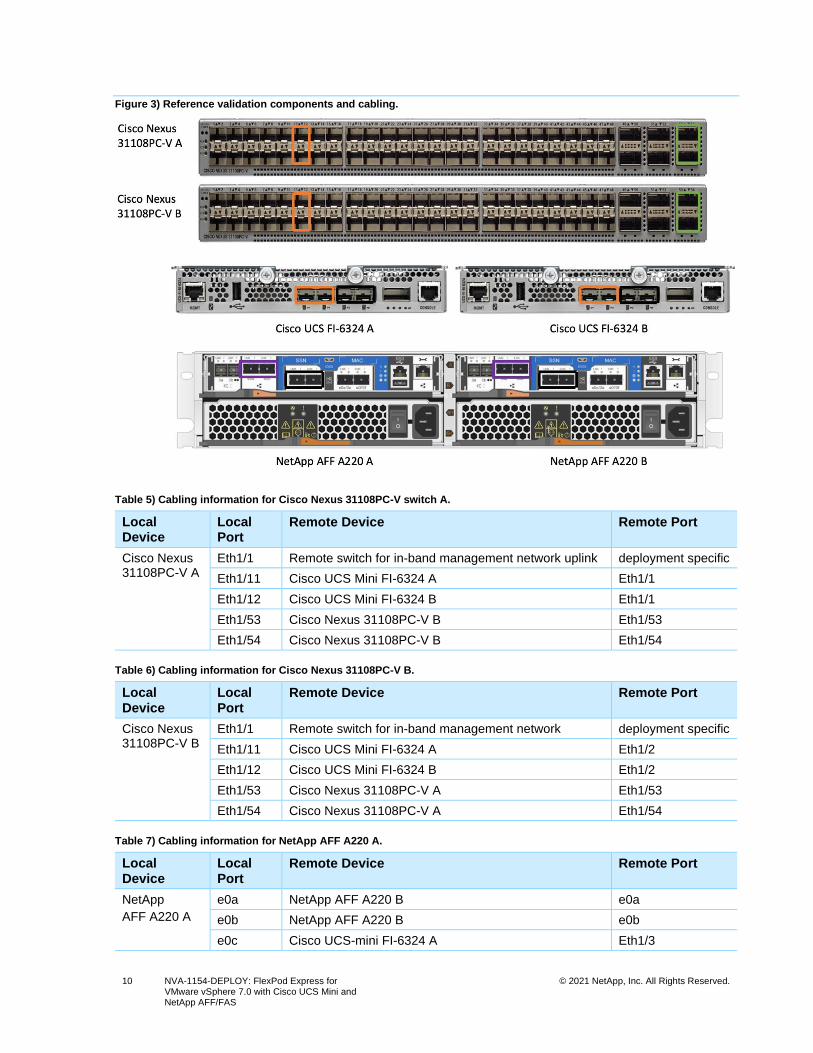
Cabling information
The reference validation cabling details are shown in Figure 3 and Table 5 through Table 10. For this
deployment guide, the console and management network of the FlexPod components are connected to
the existing console and management network and are not documented in the cabling information below.
10 NVA-1154-DEPLOY: FlexPod Express for VMware vSphere 7.0 with Cisco UCS Mini and NetApp AFF/FAS
© 2021 NetApp, Inc. All Rights Reserved.
Figure 3) Reference validation components and cabling.
Table 5) Cabling information for Cisco Nexus 31108PC-V switch A.
Local Device
Local Port
Remote Device Remote Port
Cisco Nexus 31108PC-V A
Eth1/1 Remote switch for in-band management network uplink deployment specific
Eth1/11 Cisco UCS Mini FI-6324 A Eth1/1
Eth1/12 Cisco UCS Mini FI-6324 B Eth1/1
Eth1/53 Cisco Nexus 31108PC-V B Eth1/53
Eth1/54 Cisco Nexus 31108PC-V B Eth1/54
Table 6) Cabling information for Cisco Nexus 31108PC-V B.
Local Device
Local Port
Remote Device Remote Port
Cisco Nexus 31108PC-V B
Eth1/1 Remote switch for in-band management network deployment specific
Eth1/11 Cisco UCS Mini FI-6324 A Eth1/2
Eth1/12 Cisco UCS Mini FI-6324 B Eth1/2
Eth1/53 Cisco Nexus 31108PC-V A Eth1/53
Eth1/54 Cisco Nexus 31108PC-V A Eth1/54
Table 7) Cabling information for NetApp AFF A220 A.
Local Device
Local Port
Remote Device Remote Port
NetApp
AFF A220 A
e0a NetApp AFF A220 B e0a
e0b NetApp AFF A220 B e0b
e0c Cisco UCS-mini FI-6324 A Eth1/3
11 NVA-1154-DEPLOY: FlexPod Express for VMware vSphere 7.0 with Cisco UCS Mini and NetApp AFF/FAS
© 2021 NetApp, Inc. All Rights Reserved.
Local Device
Local Port
Remote Device Remote Port
e0d Cisco UCS-mini FI-6324 B Eth1/3
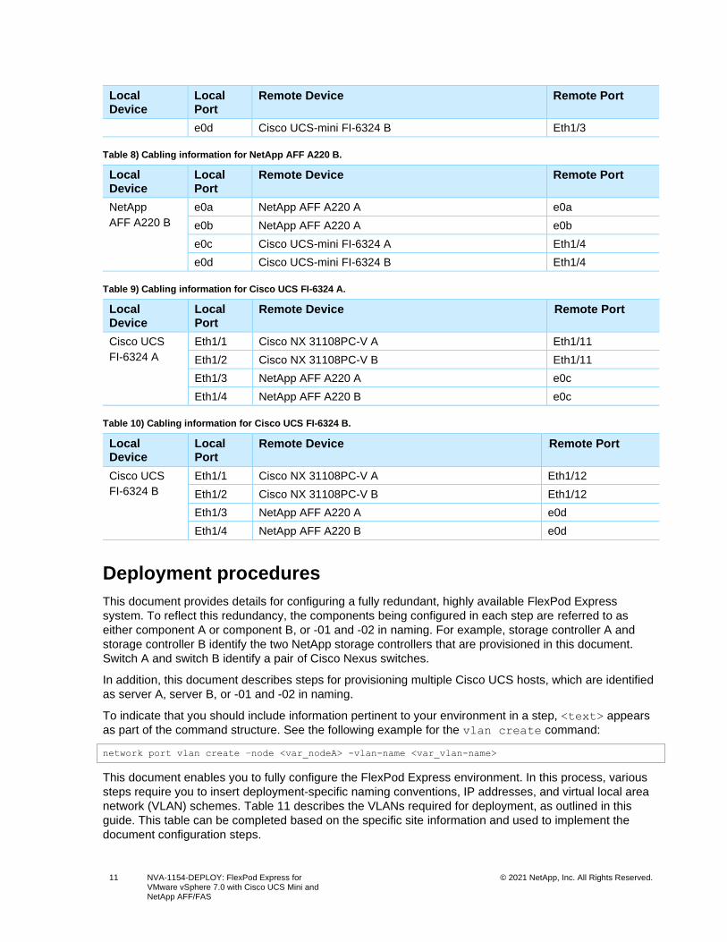
Table 8) Cabling information for NetApp AFF A220 B.
Local Device
Local Port
Remote Device Remote Port
NetApp
AFF A220 B
e0a NetApp AFF A220 A e0a
e0b NetApp AFF A220 A e0b
e0c Cisco UCS-mini FI-6324 A Eth1/4
e0d Cisco UCS-mini FI-6324 B Eth1/4
Table 9) Cabling information for Cisco UCS FI-6324 A.
Local Device
Local Port
Remote Device Remote Port
Cisco UCS
FI-6324 A
Eth1/1 Cisco NX 31108PC-V A Eth1/11
Eth1/2 Cisco NX 31108PC-V B Eth1/11
Eth1/3 NetApp AFF A220 A e0c
Eth1/4 NetApp AFF A220 B e0c
Table 10) Cabling information for Cisco UCS FI-6324 B.
Local Device
Local Port
Remote Device Remote Port
Cisco UCS
FI-6324 B
Eth1/1 Cisco NX 31108PC-V A Eth1/12
Eth1/2 Cisco NX 31108PC-V B Eth1/12
Eth1/3 NetApp AFF A220 A e0d
Eth1/4 NetApp AFF A220 B e0d
Deployment procedures
This document provides details for configuring a fully redundant, highly available FlexPod Express
system. To reflect this redundancy, the components being configured in each step are referred to as
either component A or component B, or -01 and -02 in naming. For example, storage controller A and
storage controller B identify the two NetApp storage controllers that are provisioned in this document.
Switch A and switch B identify a pair of Cisco Nexus switches.
In addition, this document describes steps for provisioning multiple Cisco UCS hosts, which are identified
as server A, server B, or -01 and -02 in naming.
To indicate that you should include information pertinent to your environment in a step, <text> appears
as part of the command structure. See the following example for the vlan create command:
network port vlan create –node <var_nodeA> -vlan-name <var_vlan-name>
This document enables you to fully configure the FlexPod Express environment. In this process, various
steps require you to insert deployment-specific naming conventions, IP addresses, and virtual local area
network (VLAN) schemes. Table 11 describes the VLANs required for deployment, as outlined in this
guide. This table can be completed based on the specific site information and used to implement the
document configuration steps.
12 NVA-1154-DEPLOY: FlexPod Express for VMware vSphere 7.0 with Cisco UCS Mini and NetApp AFF/FAS
© 2021 NetApp, Inc. All Rights Reserved.
Note: For this validation, existing network infrastructure is used for the out-of-band management connectivity of the FlexPod components and those details are not included in this guide.
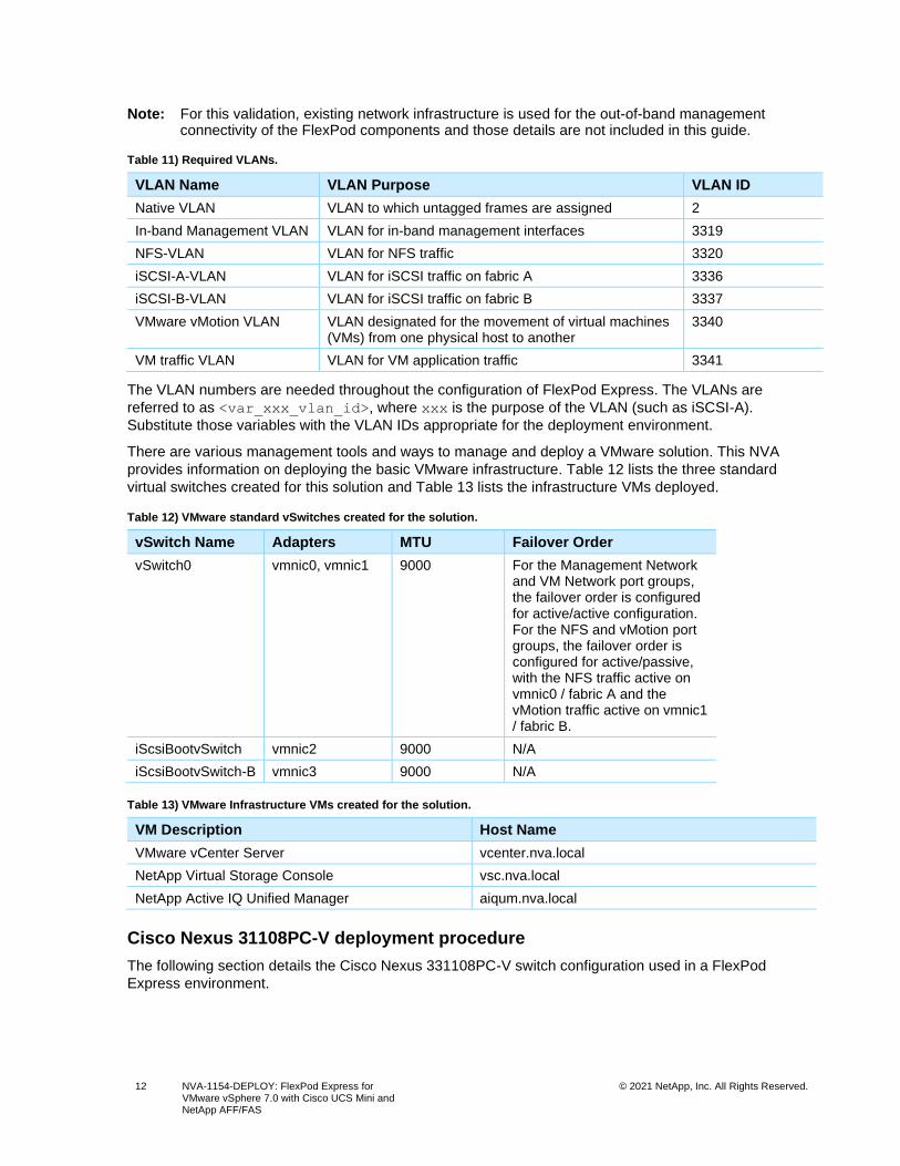
Table 11) Required VLANs.
VLAN Name VLAN Purpose VLAN ID
Native VLAN VLAN to which untagged frames are assigned 2
In-band Management VLAN VLAN for in-band management interfaces 3319
NFS-VLAN VLAN for NFS traffic 3320
iSCSI-A-VLAN VLAN for iSCSI traffic on fabric A 3336
iSCSI-B-VLAN VLAN for iSCSI traffic on fabric B 3337
VMware vMotion VLAN VLAN designated for the movement of virtual machines (VMs) from one physical host to another
3340
VM traffic VLAN VLAN for VM application traffic 3341
The VLAN numbers are needed throughout the configuration of FlexPod Express. The VLANs are
referred to as <var_xxx_vlan_id>, where xxx is the purpose of the VLAN (such as iSCSI-A).
Substitute those variables with the VLAN IDs appropriate for the deployment environment.
There are various management tools and ways to manage and deploy a VMware solution. This NVA
provides information on deploying the basic VMware infrastructure. Table 12 lists the three standard
virtual switches created for this solution and Table 13 lists the infrastructure VMs deployed.
Table 12) VMware standard vSwitches created for the solution.
vSwitch Name Adapters MTU Failover Order
vSwitch0 vmnic0, vmnic1 9000 For the Management Network and VM Network port groups, the failover order is configured for active/active configuration. For the NFS and vMotion port groups, the failover order is configured for active/passive, with the NFS traffic active on vmnic0 / fabric A and the vMotion traffic active on vmnic1 / fabric B.
iScsiBootvSwitch vmnic2 9000 N/A
iScsiBootvSwitch-B vmnic3 9000 N/A
Table 13) VMware Infrastructure VMs created for the solution.
VM Description Host Name
VMware vCenter Server vcenter.nva.local
NetApp Virtual Storage Console vsc.nva.local
NetApp Active IQ Unified Manager aiqum.nva.local
Cisco Nexus 31108PC-V deployment procedure
The following section details the Cisco Nexus 331108PC-V switch configuration used in a FlexPod
Express environment.
13 NVA-1154-DEPLOY: FlexPod Express for VMware vSphere 7.0 with Cisco UCS Mini and NetApp AFF/FAS
© 2021 NetApp, Inc. All Rights Reserved.
Initial setup of Cisco Nexus 31108PC-V switch
The following procedures describe how to configure the Cisco Nexus switches for use in a base FlexPod
Express environment.
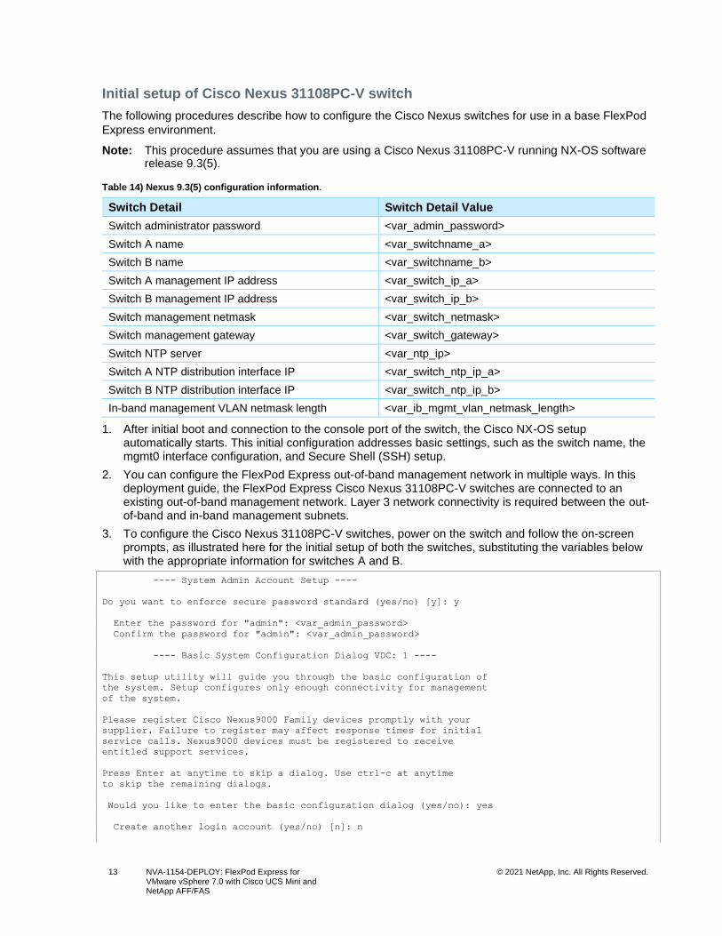
Note: This procedure assumes that you are using a Cisco Nexus 31108PC-V running NX-OS software release 9.3(5).
Table 14) Nexus 9.3(5) configuration information.
Switch Detail Switch Detail Value
Switch administrator password <var_admin_password>
Switch A name <var_switchname_a>
Switch B name <var_switchname_b>
Switch A management IP address <var_switch_ip_a>
Switch B management IP address <var_switch_ip_b>
Switch management netmask <var_switch_netmask>
Switch management gateway <var_switch_gateway>
Switch NTP server <var_ntp_ip>
Switch A NTP distribution interface IP <var_switch_ntp_ip_a>
Switch B NTP distribution interface IP <var_switch_ntp_ip_b>
In-band management VLAN netmask length <var_ib_mgmt_vlan_netmask_length>
1. After initial boot and connection to the console port of the switch, the Cisco NX-OS setup automatically starts. This initial configuration addresses basic settings, such as the switch name, the mgmt0 interface configuration, and Secure Shell (SSH) setup.
2. You can configure the FlexPod Express out-of-band management network in multiple ways. In this deployment guide, the FlexPod Express Cisco Nexus 31108PC-V switches are connected to an existing out-of-band management network. Layer 3 network connectivity is required between the out-of-band and in-band management subnets.
3. To configure the Cisco Nexus 31108PC-V switches, power on the switch and follow the on-screen prompts, as illustrated here for the initial setup of both the switches, substituting the variables below with the appropriate information for switches A and B.
---- System Admin Account Setup ----
Do you want to enforce secure password standard (yes/no) [y]: y
Enter the password for "admin": <var_admin_password>
Confirm the password for "admin": <var_admin_password>
---- Basic System Configuration Dialog VDC: 1 ----
This setup utility will guide you through the basic configuration of
the system. Setup configures only enough connectivity for management
of the system.
Please register Cisco Nexus9000 Family devices promptly with your
supplier. Failure to register may affect response times for initial
service calls. Nexus9000 devices must be registered to receive
entitled support services.
Press Enter at anytime to skip a dialog. Use ctrl-c at anytime
to skip the remaining dialogs.
Would you like to enter the basic configuration dialog (yes/no): yes
Create another login account (yes/no) [n]: n
14 NVA-1154-DEPLOY: FlexPod Express for VMware vSphere 7.0 with Cisco UCS Mini and NetApp AFF/FAS
© 2021 NetApp, Inc. All Rights Reserved.
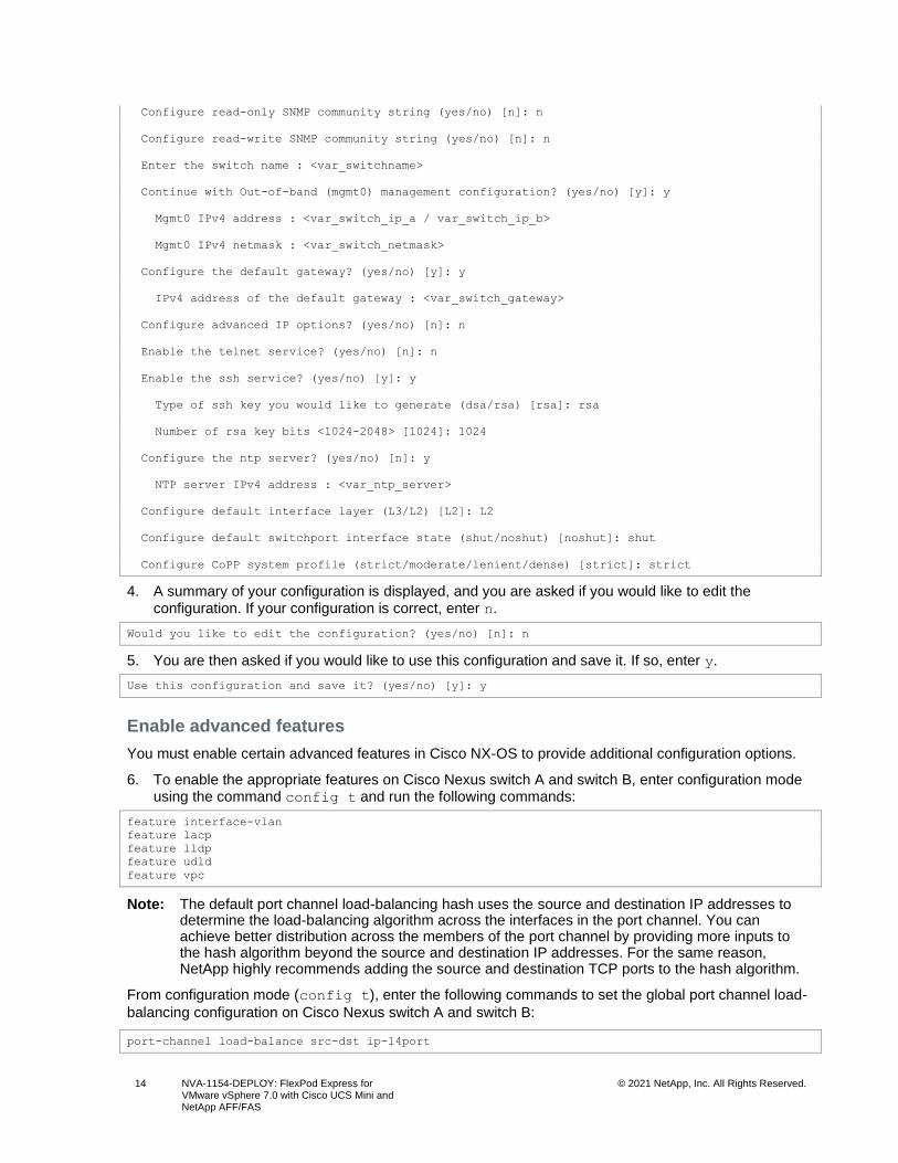
Configure read-only SNMP community string (yes/no) [n]: n
Configure read-write SNMP community string (yes/no) [n]: n
Enter the switch name : <var_switchname>
Continue with Out-of-band (mgmt0) management configuration? (yes/no) [y]: y
Mgmt0 IPv4 address : <var_switch_ip_a / var_switch_ip_b>
Mgmt0 IPv4 netmask : <var_switch_netmask>
Configure the default gateway? (yes/no) [y]: y
IPv4 address of the default gateway : <var_switch_gateway>
Configure advanced IP options? (yes/no) [n]: n
Enable the telnet service? (yes/no) [n]: n
Enable the ssh service? (yes/no) [y]: y
Type of ssh key you would like to generate (dsa/rsa) [rsa]: rsa
Number of rsa key bits <1024-2048> [1024]: 1024
Configure the ntp server? (yes/no) [n]: y
NTP server IPv4 address : <var_ntp_server>
Configure default interface layer (L3/L2) [L2]: L2
Configure default switchport interface state (shut/noshut) [noshut]: shut
Configure CoPP system profile (strict/moderate/lenient/dense) [strict]: strict
4. A summary of your configuration is displayed, and you are asked if you would like to edit the configuration. If your configuration is correct, enter n.
Would you like to edit the configuration? (yes/no) [n]: n
5. You are then asked if you would like to use this configuration and save it. If so, enter y.
Use this configuration and save it? (yes/no) [y]: y
Enable advanced features
You must enable certain advanced features in Cisco NX-OS to provide additional configuration options.
6. To enable the appropriate features on Cisco Nexus switch A and switch B, enter configuration mode using the command config t and run the following commands:
feature interface-vlan
feature lacp
feature lldp
feature udld
feature vpc
Note: The default port channel load-balancing hash uses the source and destination IP addresses to determine the load-balancing algorithm across the interfaces in the port channel. You can achieve better distribution across the members of the port channel by providing more inputs to the hash algorithm beyond the source and destination IP addresses. For the same reason, NetApp highly recommends adding the source and destination TCP ports to the hash algorithm.
From configuration mode (config t), enter the following commands to set the global port channel load-
balancing configuration on Cisco Nexus switch A and switch B:
port-channel load-balance src-dst ip-l4port
15 NVA-1154-DEPLOY: FlexPod Express for VMware vSphere 7.0 with Cisco UCS Mini and NetApp AFF/FAS
© 2021 NetApp, Inc. All Rights Reserved.
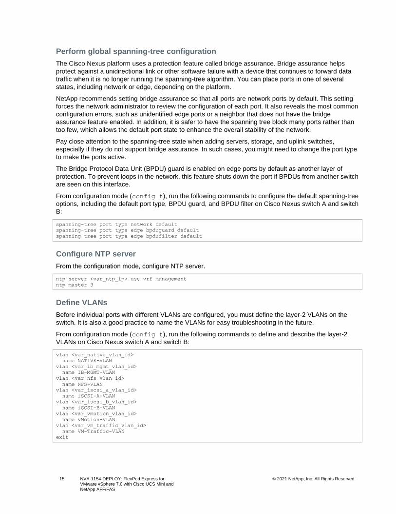
Perform global spanning-tree configuration
The Cisco Nexus platform uses a protection feature called bridge assurance. Bridge assurance helps
protect against a unidirectional link or other software failure with a device that continues to forward data
traffic when it is no longer running the spanning-tree algorithm. You can place ports in one of several
states, including network or edge, depending on the platform.
NetApp recommends setting bridge assurance so that all ports are network ports by default. This setting
forces the network administrator to review the configuration of each port. It also reveals the most common
configuration errors, such as unidentified edge ports or a neighbor that does not have the bridge
assurance feature enabled. In addition, it is safer to have the spanning tree block many ports rather than
too few, which allows the default port state to enhance the overall stability of the network.
Pay close attention to the spanning-tree state when adding servers, storage, and uplink switches,
especially if they do not support bridge assurance. In such cases, you might need to change the port type
to make the ports active.
The Bridge Protocol Data Unit (BPDU) guard is enabled on edge ports by default as another layer of
protection. To prevent loops in the network, this feature shuts down the port if BPDUs from another switch
are seen on this interface.
From configuration mode (config t), run the following commands to configure the default spanning-tree
options, including the default port type, BPDU guard, and BPDU filter on Cisco Nexus switch A and switch
B:
spanning-tree port type network default
spanning-tree port type edge bpduguard default
spanning-tree port type edge bpdufilter default
Configure NTP server
From the configuration mode, configure NTP server.
ntp server <var_ntp_ip> use-vrf management
ntp master 3
Define VLANs
Before individual ports with different VLANs are configured, you must define the layer-2 VLANs on the
switch. It is also a good practice to name the VLANs for easy troubleshooting in the future.
From configuration mode (config t), run the following commands to define and describe the layer-2
VLANs on Cisco Nexus switch A and switch B:
vlan <var_native_vlan_id>
name NATIVE-VLAN
vlan <var_ib_mgmt_vlan_id>
name IB-MGMT-VLAN
vlan <var_nfs_vlan_id>
name NFS-VLAN
vlan <var_iscsi_a_vlan_id>
name iSCSI-A-VLAN
vlan <var_iscsi_b_vlan_id>
name iSCSI-B-VLAN
vlan <var_vmotion_vlan_id>
name vMotion-VLAN
vlan <var_vm_traffic_vlan_id>
name VM-Traffic-VLAN
exit
16 NVA-1154-DEPLOY: FlexPod Express for VMware vSphere 7.0 with Cisco UCS Mini and NetApp AFF/FAS
© 2021 NetApp, Inc. All Rights Reserved.
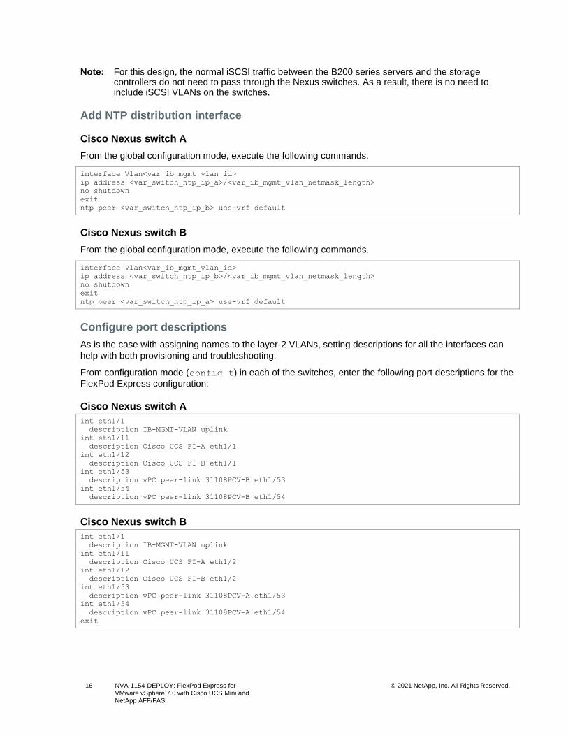
Note: For this design, the normal iSCSI traffic between the B200 series servers and the storage controllers do not need to pass through the Nexus switches. As a result, there is no need to include iSCSI VLANs on the switches.
Add NTP distribution interface
Cisco Nexus switch A
From the global configuration mode, execute the following commands.
interface Vlan<var_ib_mgmt_vlan_id>
ip address <var_switch_ntp_ip_a>/<var_ib_mgmt_vlan_netmask_length>
no shutdown
exit
ntp peer <var_switch_ntp_ip_b> use-vrf default
Cisco Nexus switch B
From the global configuration mode, execute the following commands.
interface Vlan<var_ib_mgmt_vlan_id>
ip address <var_switch_ntp_ip_b>/<var_ib_mgmt_vlan_netmask_length>
no shutdown
exit
ntp peer <var_switch_ntp_ip_a> use-vrf default
Configure port descriptions
As is the case with assigning names to the layer-2 VLANs, setting descriptions for all the interfaces can
help with both provisioning and troubleshooting.
From configuration mode (config t) in each of the switches, enter the following port descriptions for the
FlexPod Express configuration:
Cisco Nexus switch A
int eth1/1
description IB-MGMT-VLAN uplink
int eth1/11
description Cisco UCS FI-A eth1/1
int eth1/12
description Cisco UCS FI-B eth1/1
int eth1/53
description vPC peer-link 31108PCV-B eth1/53
int eth1/54
description vPC peer-link 31108PCV-B eth1/54
Cisco Nexus switch B
int eth1/1
description IB-MGMT-VLAN uplink
int eth1/11
description Cisco UCS FI-A eth1/2
int eth1/12
description Cisco UCS FI-B eth1/2
int eth1/53
description vPC peer-link 31108PCV-A eth1/53
int eth1/54
description vPC peer-link 31108PCV-A eth1/54
exit
17 NVA-1154-DEPLOY: FlexPod Express for VMware vSphere 7.0 with Cisco UCS Mini and NetApp AFF/FAS
© 2021 NetApp, Inc. All Rights Reserved.
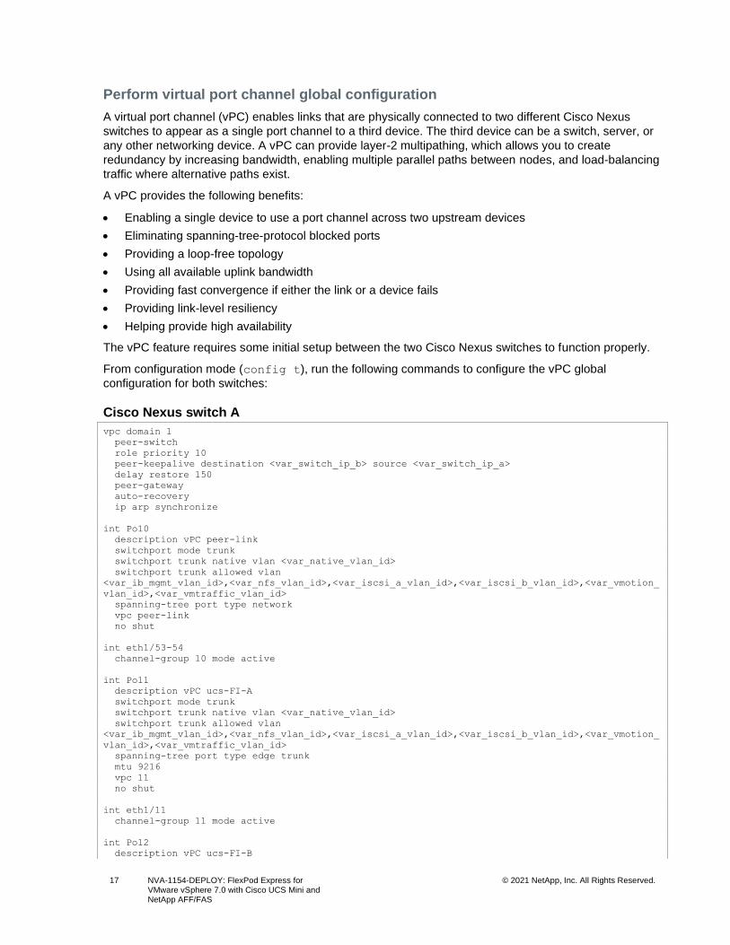
Perform virtual port channel global configuration
A virtual port channel (vPC) enables links that are physically connected to two different Cisco Nexus
switches to appear as a single port channel to a third device. The third device can be a switch, server, or
any other networking device. A vPC can provide layer-2 multipathing, which allows you to create
redundancy by increasing bandwidth, enabling multiple parallel paths between nodes, and load-balancing
traffic where alternative paths exist.
A vPC provides the following benefits:
• Enabling a single device to use a port channel across two upstream devices
• Eliminating spanning-tree-protocol blocked ports
• Providing a loop-free topology
• Using all available uplink bandwidth
• Providing fast convergence if either the link or a device fails
• Providing link-level resiliency
• Helping provide high availability
The vPC feature requires some initial setup between the two Cisco Nexus switches to function properly.
From configuration mode (config t), run the following commands to configure the vPC global
configuration for both switches:
Cisco Nexus switch A
vpc domain 1
peer-switch
role priority 10
peer-keepalive destination <var_switch_ip_b> source <var_switch_ip_a>
delay restore 150
peer-gateway
auto-recovery
ip arp synchronize
int Po10
description vPC peer-link
switchport mode trunk
switchport trunk native vlan <var_native_vlan_id>
switchport trunk allowed vlan
<var_ib_mgmt_vlan_id>,<var_nfs_vlan_id>,<var_iscsi_a_vlan_id>,<var_iscsi_b_vlan_id>,<var_vmotion_
vlan_id>,<var_vmtraffic_vlan_id>
spanning-tree port type network
vpc peer-link
no shut
int eth1/53-54
channel-group 10 mode active
int Po11
description vPC ucs-FI-A
switchport mode trunk
switchport trunk native vlan <var_native_vlan_id>
switchport trunk allowed vlan
<var_ib_mgmt_vlan_id>,<var_nfs_vlan_id>,<var_iscsi_a_vlan_id>,<var_iscsi_b_vlan_id>,<var_vmotion_
vlan_id>,<var_vmtraffic_vlan_id>
spanning-tree port type edge trunk
mtu 9216
vpc 11
no shut
int eth1/11
channel-group 11 mode active
int Po12
description vPC ucs-FI-B
18 NVA-1154-DEPLOY: FlexPod Express for VMware vSphere 7.0 with Cisco UCS Mini and NetApp AFF/FAS
© 2021 NetApp, Inc. All Rights Reserved.
switchport mode trunk
switchport trunk native vlan <var_native_vlan_id>
switchport trunk allowed vlan
<var_oob_mgmt_vlan_id>,<var_nfs_vlan_id>,<var_iscsi_a_vlan_id>,<var_iscsi_b_vlan_id>,<var_vmotion
_vlan_id>,<var_vmtraffic_vlan_id>
spanning-tree port type edge trunk
mtu 9216
vpc 12
no shut
int eth1/12
channel-group 12 mode active
exit
exit
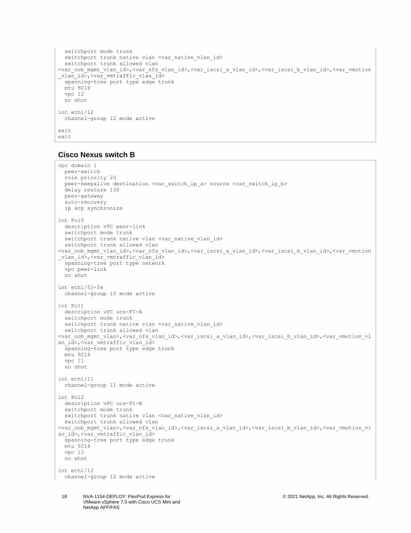
Cisco Nexus switch B
vpc domain 1
peer-switch
role priority 20
peer-keepalive destination <var_switch_ip_a> source <var_switch_ip_b>
delay restore 150
peer-gateway
auto-recovery
ip arp synchronize
int Po10
description vPC peer-link
switchport mode trunk
switchport trunk native vlan <var_native_vlan_id>
switchport trunk allowed vlan
<var_oob_mgmt_vlan_id>,<var_nfs_vlan_id>,<var_iscsi_a_vlan_id>,<var_iscsi_b_vlan_id>,<var_vmotion
_vlan_id>,<var_vmtraffic_vlan_id>
spanning-tree port type network
vpc peer-link
no shut
int eth1/53-54
channel-group 10 mode active
int Po11
description vPC ucs-FI-A
switchport mode trunk
switchport trunk native vlan <var_native_vlan_id>
switchport trunk allowed vlan
<var_oob_mgmt_vlan>,<var_nfs_vlan_id>,<var_iscsi_a_vlan_id>,<var_iscsi_b_vlan_id>,<var_vmotion_vl
an_id>,<var_vmtraffic_vlan_id>
spanning-tree port type edge trunk
mtu 9216
vpc 11
no shut
int eth1/11
channel-group 11 mode active
int Po12
description vPC ucs-FI-B
switchport mode trunk
switchport trunk native vlan <var_native_vlan_id>
switchport trunk allowed vlan
<var_oob_mgmt_vlan>,<var_nfs_vlan_id>,<var_iscsi_a_vlan_id>,<var_iscsi_b_vlan_id>,<var_vmotion_vl
an_id>,<var_vmtraffic_vlan_id>
spanning-tree port type edge trunk
mtu 9216
vpc 12
no shut
int eth1/12
channel-group 12 mode active
19 NVA-1154-DEPLOY: FlexPod Express for VMware vSphere 7.0 with Cisco UCS Mini and NetApp AFF/FAS
© 2021 NetApp, Inc. All Rights Reserved.
exit
exit
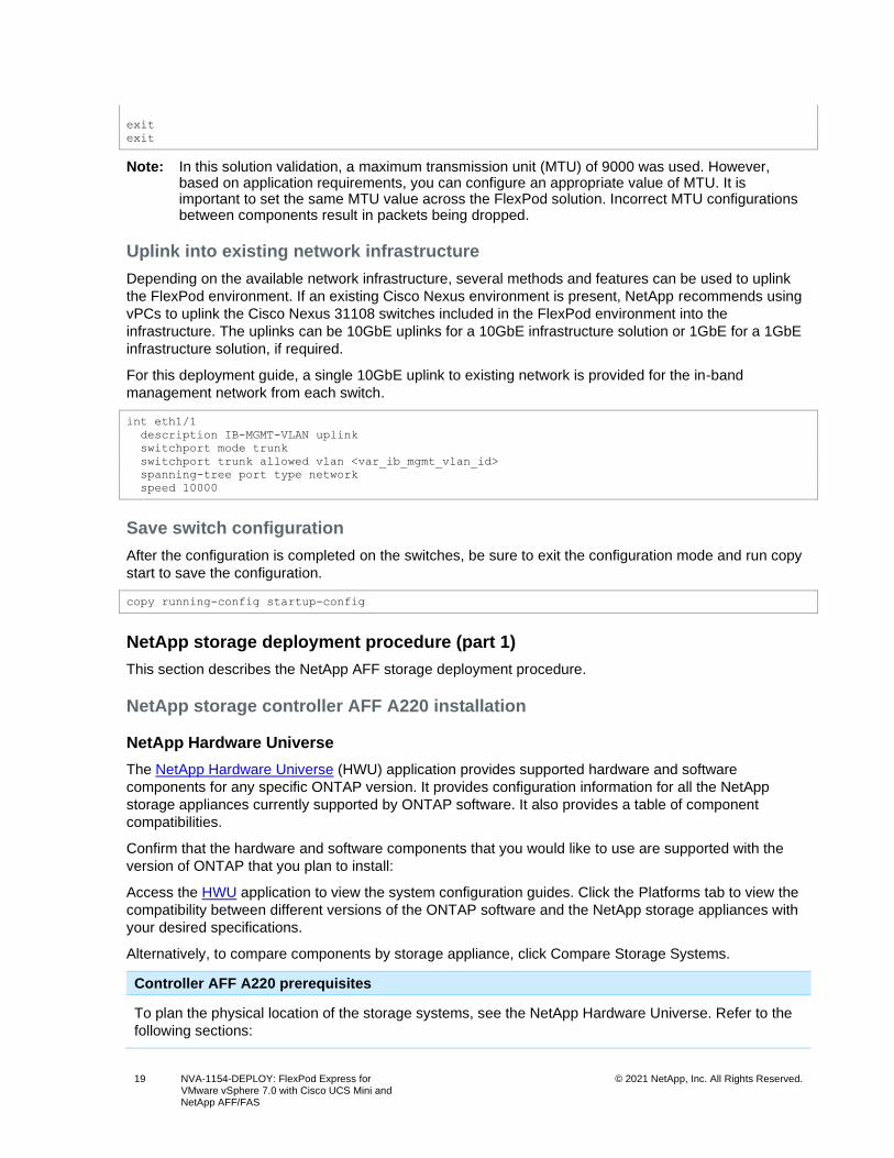
Note: In this solution validation, a maximum transmission unit (MTU) of 9000 was used. However, based on application requirements, you can configure an appropriate value of MTU. It is important to set the same MTU value across the FlexPod solution. Incorrect MTU configurations between components result in packets being dropped.
Uplink into existing network infrastructure
Depending on the available network infrastructure, several methods and features can be used to uplink
the FlexPod environment. If an existing Cisco Nexus environment is present, NetApp recommends using
vPCs to uplink the Cisco Nexus 31108 switches included in the FlexPod environment into the
infrastructure. The uplinks can be 10GbE uplinks for a 10GbE infrastructure solution or 1GbE for a 1GbE
infrastructure solution, if required.
For this deployment guide, a single 10GbE uplink to existing network is provided for the in-band
management network from each switch.
int eth1/1
description IB-MGMT-VLAN uplink
switchport mode trunk
switchport trunk allowed vlan <var_ib_mgmt_vlan_id>
spanning-tree port type network
speed 10000
Save switch configuration
After the configuration is completed on the switches, be sure to exit the configuration mode and run copy
start to save the configuration.
copy running-config startup-config
NetApp storage deployment procedure (part 1)
This section describes the NetApp AFF storage deployment procedure.
NetApp storage controller AFF A220 installation
NetApp Hardware Universe
The NetApp Hardware Universe (HWU) application provides supported hardware and software
components for any specific ONTAP version. It provides configuration information for all the NetApp
storage appliances currently supported by ONTAP software. It also provides a table of component
compatibilities.
Confirm that the hardware and software components that you would like to use are supported with the
version of ONTAP that you plan to install:
Access the HWU application to view the system configuration guides. Click the Platforms tab to view the
compatibility between different versions of the ONTAP software and the NetApp storage appliances with
your desired specifications.
Alternatively, to compare components by storage appliance, click Compare Storage Systems.
Controller AFF A220 prerequisites
To plan the physical location of the storage systems, see the NetApp Hardware Universe. Refer to the
following sections:
20 NVA-1154-DEPLOY: FlexPod Express for VMware vSphere 7.0 with Cisco UCS Mini and NetApp AFF/FAS
© 2021 NetApp, Inc. All Rights Reserved.
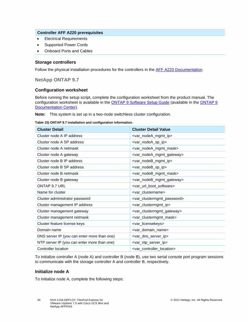
Controller AFF A220 prerequisites
• Electrical Requirements
• Supported Power Cords
• Onboard Ports and Cables
Storage controllers
Follow the physical installation procedures for the controllers in the AFF A220 Documentation.
NetApp ONTAP 9.7
Configuration worksheet
Before running the setup script, complete the configuration worksheet from the product manual. The
configuration worksheet is available in the ONTAP 9 Software Setup Guide (available in the ONTAP 9
Documentation Center).
Note: This system is set up in a two-node switchless cluster configuration.
Table 15) ONTAP 9.7 installation and configuration information.
Cluster Detail Cluster Detail Value
Cluster node A IP address <var_nodeA_mgmt_ip>
Cluster node A SP address <var_nodeA_sp_ip>
Cluster node A netmask <var_nodeA_mgmt_mask>
Cluster node A gateway <var_nodeA_mgmt_gateway>
Cluster node B IP address <var_nodeB_mgmt_ip>
Cluster node B SP address <var_nodeB_sp_ip>
Cluster node B netmask <var_nodeB_mgmt_mask>
Cluster node B gateway <var_nodeB_mgmt_gateway>
ONTAP 9.7 URL <var_url_boot_software>
Name for cluster <var_clustername>
Cluster administrator password <var_clustermgmt_password>
Cluster management IP address <var_clustermgmt_ip>
Cluster management gateway <var_clustermgmt_gateway>
Cluster management netmask <var_clustermgmt_mask>
Cluster feature license keys <var_licensekeys>
Domain name <var_domain_name>
DNS server IP (you can enter more than one) <var_dns_server_ip>
NTP server IP (you can enter more than one) <var_ntp_server_ip>
Controller location <var_controller_location>
To initialize controller A (node A) and controller B (node B), use two serial console port program sessions
to communicate with the storage controller A and controller B, respectively.
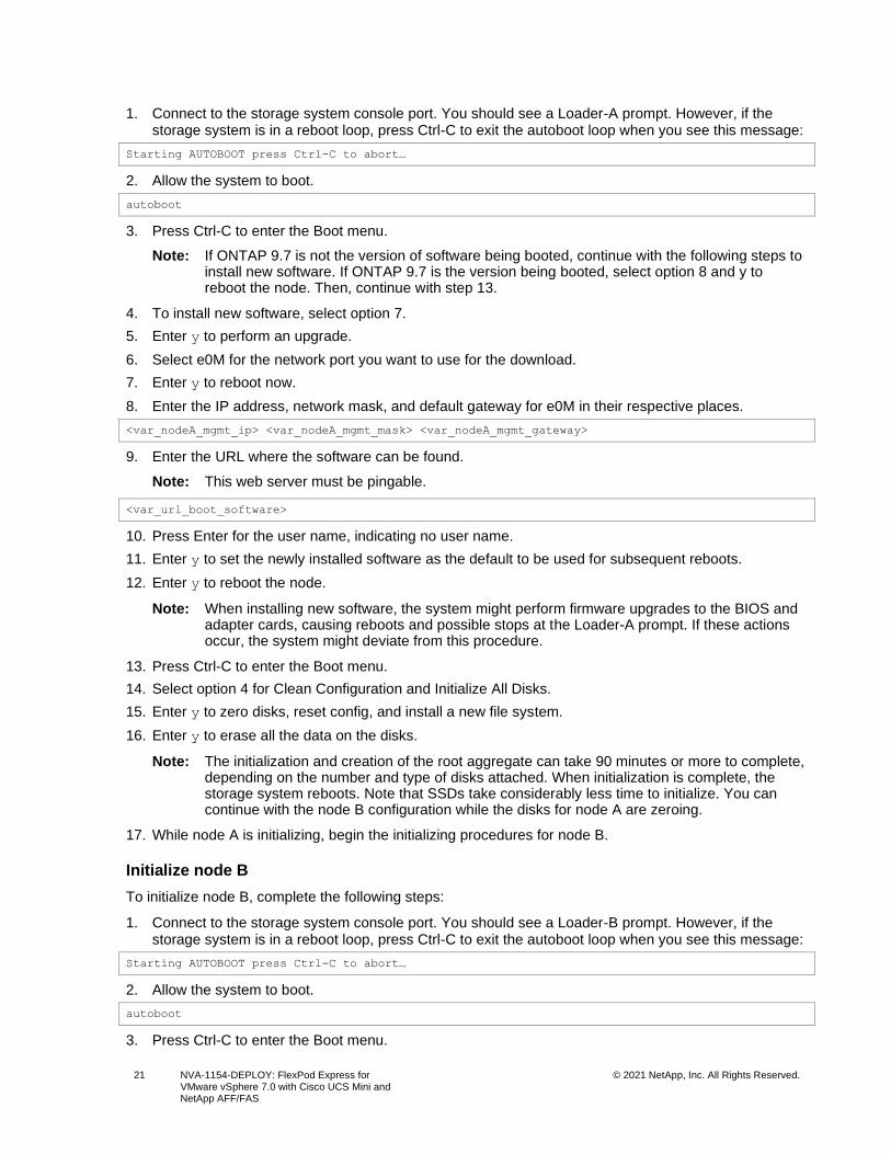
Initialize node A
To initialize node A, complete the following steps:
21 NVA-1154-DEPLOY: FlexPod Express for VMware vSphere 7.0 with Cisco UCS Mini and NetApp AFF/FAS
© 2021 NetApp, Inc. All Rights Reserved.
1. Connect to the storage system console port. You should see a Loader-A prompt. However, if the storage system is in a reboot loop, press Ctrl-C to exit the autoboot loop when you see this message:
Starting AUTOBOOT press Ctrl-C to abort…
2. Allow the system to boot.
autoboot
3. Press Ctrl-C to enter the Boot menu.
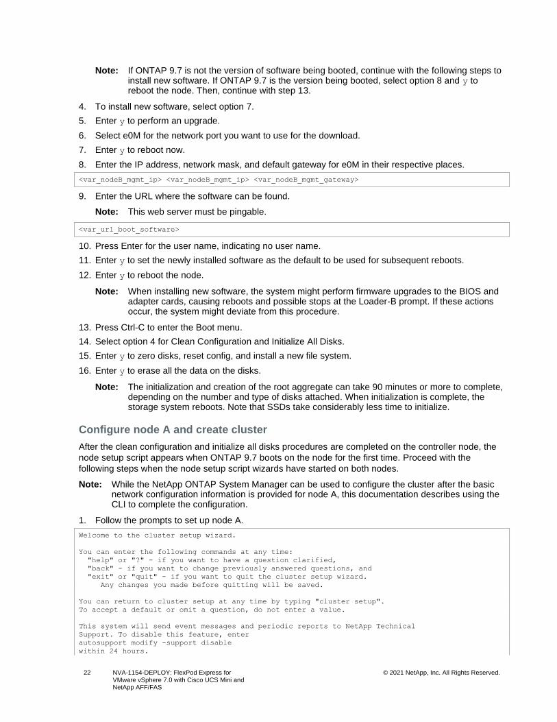
Note: If ONTAP 9.7 is not the version of software being booted, continue with the following steps to install new software. If ONTAP 9.7 is the version being booted, select option 8 and y to reboot the node. Then, continue with step 13.
4. To install new software, select option 7.
5. Enter y to perform an upgrade.
6. Select e0M for the network port you want to use for the download.
7. Enter y to reboot now.
8. Enter the IP address, network mask, and default gateway for e0M in their respective places.
<var_nodeA_mgmt_ip> <var_nodeA_mgmt_mask> <var_nodeA_mgmt_gateway>
9. Enter the URL where the software can be found.
Note: This web server must be pingable.
<var_url_boot_software>
10. Press Enter for the user name, indicating no user name.
11. Enter y to set the newly installed software as the default to be used for subsequent reboots.
12. Enter y to reboot the node.
Note: When installing new software, the system might perform firmware upgrades to the BIOS and adapter cards, causing reboots and possible stops at the Loader-A prompt. If these actions occur, the system might deviate from this procedure.
13. Press Ctrl-C to enter the Boot menu.
14. Select option 4 for Clean Configuration and Initialize All Disks.
15. Enter y to zero disks, reset config, and install a new file system.
16. Enter y to erase all the data on the disks.
Note: The initialization and creation of the root aggregate can take 90 minutes or more to complete, depending on the number and type of disks attached. When initialization is complete, the storage system reboots. Note that SSDs take considerably less time to initialize. You can continue with the node B configuration while the disks for node A are zeroing.
17. While node A is initializing, begin the initializing procedures for node B.
Initialize node B
To initialize node B, complete the following steps:
1. Connect to the storage system console port. You should see a Loader-B prompt. However, if the storage system is in a reboot loop, press Ctrl-C to exit the autoboot loop when you see this message:
Starting AUTOBOOT press Ctrl-C to abort…
2. Allow the system to boot.
autoboot
3. Press Ctrl-C to enter the Boot menu.
22 NVA-1154-DEPLOY: FlexPod Express for VMware vSphere 7.0 with Cisco UCS Mini and NetApp AFF/FAS
© 2021 NetApp, Inc. All Rights Reserved.
Note: If ONTAP 9.7 is not the version of software being booted, continue with the following steps to install new software. If ONTAP 9.7 is the version being booted, select option 8 and y to reboot the node. Then, continue with step 13.
4. To install new software, select option 7.
5. Enter y to perform an upgrade.
6. Select e0M for the network port you want to use for the download.
7. Enter y to reboot now.
8. Enter the IP address, network mask, and default gateway for e0M in their respective places.
<var_nodeB_mgmt_ip> <var_nodeB_mgmt_ip> <var_nodeB_mgmt_gateway>
9. Enter the URL where the software can be found.
Note: This web server must be pingable.
<var_url_boot_software>
10. Press Enter for the user name, indicating no user name.
11. Enter y to set the newly installed software as the default to be used for subsequent reboots.
12. Enter y to reboot the node.
Note: When installing new software, the system might perform firmware upgrades to the BIOS and adapter cards, causing reboots and possible stops at the Loader-B prompt. If these actions occur, the system might deviate from this procedure.
13. Press Ctrl-C to enter the Boot menu.
14. Select option 4 for Clean Configuration and Initialize All Disks.
15. Enter y to zero disks, reset config, and install a new file system.
16. Enter y to erase all the data on the disks.
Note: The initialization and creation of the root aggregate can take 90 minutes or more to complete, depending on the number and type of disks attached. When initialization is complete, the storage system reboots. Note that SSDs take considerably less time to initialize.
Configure node A and create cluster
After the clean configuration and initialize all disks procedures are completed on the controller node, the
node setup script appears when ONTAP 9.7 boots on the node for the first time. Proceed with the
following steps when the node setup script wizards have started on both nodes.
Note: While the NetApp ONTAP System Manager can be used to configure the cluster after the basic network configuration information is provided for node A, this documentation describes using the CLI to complete the configuration.
1. Follow the prompts to set up node A.
Welcome to the cluster setup wizard.
You can enter the following commands at any time:
"help" or "?" - if you want to have a question clarified,
"back" - if you want to change previously answered questions, and
"exit" or "quit" - if you want to quit the cluster setup wizard.
Any changes you made before quitting will be saved.
You can return to cluster setup at any time by typing "cluster setup".
To accept a default or omit a question, do not enter a value.
This system will send event messages and periodic reports to NetApp Technical
Support. To disable this feature, enter
autosupport modify -support disable
within 24 hours.
23 NVA-1154-DEPLOY: FlexPod Express for VMware vSphere 7.0 with Cisco UCS Mini and NetApp AFF/FAS
© 2021 NetApp, Inc. All Rights Reserved.
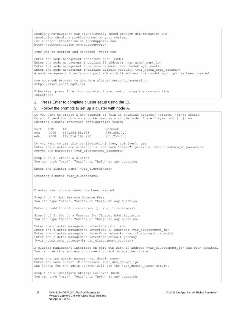
Enabling AutoSupport can significantly speed problem determination and
resolution should a problem occur on your system.
For further information on AutoSupport, see:
http://support.netapp.com/autosupport/
Type yes to confirm and continue {yes}: yes
Enter the node management interface port [e0M]:
Enter the node management interface IP address: <var_nodeA_mgmt_ip>
Enter the node management interface netmask: <var_nodeA_mgmt_mask>
Enter the node management interface default gateway: <var_nodeA_mgmt_gateway>
A node management interface on port e0M with IP address <var_nodeA_mgmt_ip> has been created.
Use your web browser to complete cluster setup by accessing
https://<var_nodeA_mgmt_ip>
Otherwise, press Enter to complete cluster setup using the command line
interface:
2. Press Enter to complete cluster setup using the CLI.
3. Follow the prompts to set up a cluster with node A.
Do you want to create a new cluster or join an existing cluster? {create, join}: create
Do you intend for this node to be used as a single node cluster? {yes, no} [no]: no
Existing cluster interface configuration found:
Port MTU IP Netmask
e0a 9000 169.254.58.158 255.255.0.0
e0b 9000 169.254.194.220 255.255.0.0
Do you want to use this configuration? {yes, no} [yes]: yes
Enter the cluster administrator's (username "admin") password: <var_clustermgmt_password>
Retype the password: <var_clustermgmt_password>
Step 1 of 5: Create a Cluster
You can type "back", "exit", or "help" at any question.
Enter the cluster name: <var_clustername>
Creating cluster <var_clustername>
…
Cluster <var_clustername> has been created.
Step 2 of 5: Add Feature License Keys
You can type "back", "exit", or "help" at any question.
Enter an additional license key []: <var_licensekeys>
Step 3 of 5: Set Up a Vserver for Cluster Administration
You can type "back", "exit", or "help" at any question.
Enter the cluster management interface port: e0M
Enter the cluster management interface IP address: <var_clustermgmt_ip>
Enter the cluster management interface netmask: <var_clustermgmt_netmask>
Enter the cluster management interface default gateway
[<var_nodeA_mgmt_gateway>]:<var_clustermgmt_gateway>
A cluster management interface on port e0M with IP address <var_clustermgmt_ip> has been created.
You can use this address to connect to and manage the cluster.
Enter the DNS domain names: <var_domain_name>
Enter the name server IP addresses: <var_dns_server_ip>
DNS lookup for the admin Vserver will use the <var_domain_name> domain.
Step 4 of 5: Configure Storage Failover (SFO)
You can type "back", "exit", or "help" at any question.
24 NVA-1154-DEPLOY: FlexPod Express for VMware vSphere 7.0 with Cisco UCS Mini and NetApp AFF/FAS
© 2021 NetApp, Inc. All Rights Reserved.
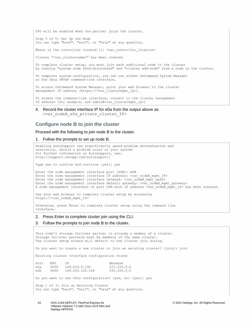
SFO will be enabled when the partner joins the cluster.
Step 5 of 5: Set Up the Node
You can type "back", "exit", or "help" at any question.
Where is the controller located []: <var_controller_location>
Cluster “<var_clustername>” has been created.
To complete cluster setup, you must join each additional node to the cluster
by running "system node show-discovered" and "cluster add-node" from a node in the cluster.
To complete system configuration, you can use either OnCommand System Manager
or the Data ONTAP command-line interface.
To access OnCommand System Manager, point your web browser to the cluster
management IP address (https://<var_clustermgmt_ip>).
To access the command-line interface, connect to the cluster management
IP address (for example, ssh admin@<var_clustermgmt_ip>)
4. Record the cluster interface IP for e0a from the output above as <var_nodeA_e0a_private_cluster_IP>
Configure node B to join the cluster
Proceed with the following to join node B to the cluster.
1. Follow the prompts to set up node B.
Enabling AutoSupport can significantly speed problem determination and
resolution, should a problem occur on your system.
For further information on AutoSupport, see:
http://support.netapp.com/autosupport/
Type yes to confirm and continue {yes}: yes
Enter the node management interface port [e0M]: e0M
Enter the node management interface IP address: <var_nodeB_mgmt_IP>
Enter the node management interface netmask: <var_nodeB_mgmt_mask>
Enter the node management interface default gateway: <var_nodeB_mgmt_gateway>
A node management interface on port e0M with IP address <var_nodeB_mgmt_IP> has been created.
Use your web browser to complete cluster setup by accessing
https://<var_nodeB_mgmt_IP>
Otherwise, press Enter to complete cluster setup using the command line
interface:
2. Press Enter to complete cluster join using the CLI.
3. Follow the prompts to join node B to the cluster.
This node's storage failover partner is already a member of a cluster.
Storage failover partners must be members of the same cluster.
The cluster setup wizard will default to the cluster join dialog.
Do you want to create a new cluster or join an existing cluster? {join}: join
Existing cluster interface configuration found:
Port MTU IP Netmask
e0a 9000 169.254.9.190 255.255.0.0
e0b 9000 169.254.125.146 255.255.0.0
Do you want to use this configuration? {yes, no} [yes]: yes
Step 1 of 3: Join an Existing Cluster
You can type "back", "exit", or "help" at any question.
25 NVA-1154-DEPLOY: FlexPod Express for VMware vSphere 7.0 with Cisco UCS Mini and NetApp AFF/FAS
© 2021 NetApp, Inc. All Rights Reserved.
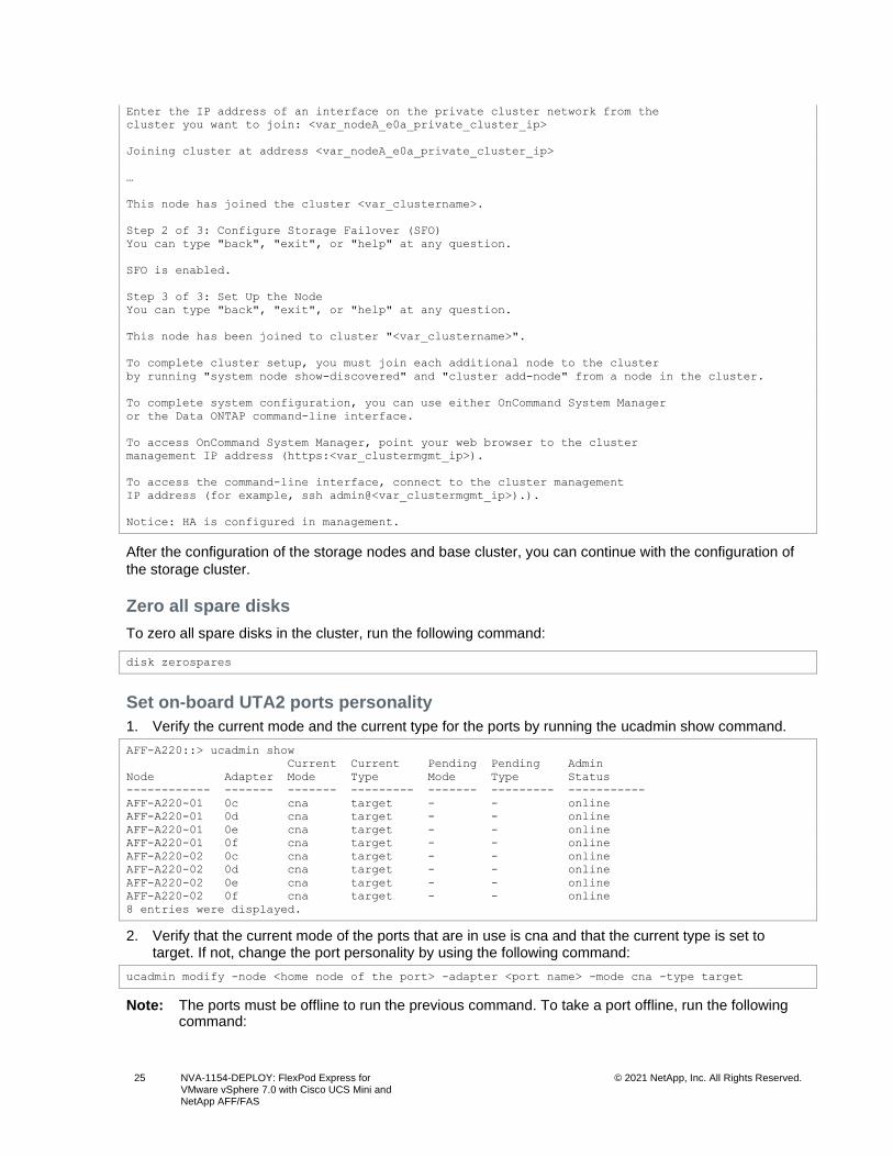
Enter the IP address of an interface on the private cluster network from the
cluster you want to join: <var_nodeA_e0a_private_cluster_ip>
Joining cluster at address <var_nodeA_e0a_private_cluster_ip>
…
This node has joined the cluster <var_clustername>.
Step 2 of 3: Configure Storage Failover (SFO)
You can type "back", "exit", or "help" at any question.
SFO is enabled.
Step 3 of 3: Set Up the Node
You can type "back", "exit", or "help" at any question.
This node has been joined to cluster "<var_clustername>".
To complete cluster setup, you must join each additional node to the cluster
by running "system node show-discovered" and "cluster add-node" from a node in the cluster.
To complete system configuration, you can use either OnCommand System Manager
or the Data ONTAP command-line interface.
To access OnCommand System Manager, point your web browser to the cluster
management IP address (https:<var_clustermgmt_ip>).
To access the command-line interface, connect to the cluster management
IP address (for example, ssh admin@<var_clustermgmt_ip>).).
Notice: HA is configured in management.
After the configuration of the storage nodes and base cluster, you can continue with the configuration of
the storage cluster.
Zero all spare disks
To zero all spare disks in the cluster, run the following command:
disk zerospares
Set on-board UTA2 ports personality
1. Verify the current mode and the current type for the ports by running the ucadmin show command.
AFF-A220::> ucadmin show
Current Current Pending Pending Admin
Node Adapter Mode Type Mode Type Status
------------ ------- ------- --------- ------- --------- -----------
AFF-A220-01 0c cna target - - online
AFF-A220-01 0d cna target - - online
AFF-A220-01 0e cna target - - online
AFF-A220-01 0f cna target - - online
AFF-A220-02 0c cna target - - online
AFF-A220-02 0d cna target - - online
AFF-A220-02 0e cna target - - online
AFF-A220-02 0f cna target - - online
8 entries were displayed.
2. Verify that the current mode of the ports that are in use is cna and that the current type is set to target. If not, change the port personality by using the following command:
ucadmin modify -node <home node of the port> -adapter <port name> -mode cna -type target
Note: The ports must be offline to run the previous command. To take a port offline, run the following command:
26 NVA-1154-DEPLOY: FlexPod Express for VMware vSphere 7.0 with Cisco UCS Mini and NetApp AFF/FAS
© 2021 NetApp, Inc. All Rights Reserved.
network fcp adapter modify -node <home node of the port> -adapter <port name> -state down
Note: If you changed the port personality, you must reboot each node for the change to take effect and then bring the port back up.
network fcp adapter modify -node <home node of the port> -adapter <port name> -state up
Enable Cisco Discovery Protocol
To enable the Cisco Discovery Protocol (CDP) on the NetApp storage controllers, run the following
command:
node run -node * options cdpd.enable on
Enable Link-layer Discovery Protocol on all Ethernet ports
Enable the exchange of Link-layer Discovery Protocol (LLDP) neighbor information between the storage
and network switches by running the following command. This command enables LLDP on all ports of all
nodes in the cluster.
node run -node * options lldp.enable on
Show and optionally rename management LIFs
1. Show the current management LIF names:
network interface show –vserver <var_clustername>
• To optionally rename the cluster management LIF name, complete the following step.
network interface rename –vserver <var_clustername> –lif <original_cluster_mgmt_lif_name> –
newname <new_cluster_mgmt_lif_name>
This document assumes that the cluster management LIF is named cluster_mgmt.
• To optionally rename the node management LIF names, complete the following step.
network interface rename -vserver <var_clustername> -lif <original_node_mgmt_lif_name> -newname
<new_node_mgmt_lif_name>
Set auto-revert on cluster management
Set the auto-revert parameter on the cluster management interface:
network interface modify –vserver <var_clustername> -lif cluster_mgmt –auto-revert true
Setting up service processor network interface
To assign a static IPv4 address to the service processor on each node, run the following commands:
system service-processor network modify –node <var_clustername>-01 -address-family IPv4 –enable
true –dhcp none –ip-address <var_nodeA_sp_ip> -netmask <var_nodeA_mgmt_mask> -gateway
<var_nodeA_mgmt_gateway>
system service-processor network modify –node <var_clustername>-02 -address-family IPv4 –enable
true –dhcp none –ip-address <var_nodeB_sp_ip> -netmask <var_nodeB_mgmt_mask> -gateway
<var_nodeB_mgmt_gateway>
Note: The service processor IP addresses should be in the same subnet as the node management IP addresses.
27 NVA-1154-DEPLOY: FlexPod Express for VMware vSphere 7.0 with Cisco UCS Mini and NetApp AFF/FAS
© 2021 NetApp, Inc. All Rights Reserved.
Enable storage failover in ONTAP
To confirm that storage failover is enabled, run the following commands in a failover pair:
1. Verify the status of storage failover.
storage failover show
Note: Both <var_clustername>-01 and <var_clustername>-02 nodes must show true for the Takeover Possible column to be able to perform a takeover. Go to step 3 if the nodes are not configured to perform a takeover.
2. Enable failover on one of the two nodes.
storage failover modify -node <var_clustername>-01 -enabled true
Note: Enabling failover on one node enables it for both nodes.
3. Verify the HA status of the two-node cluster.
Note: This step is not applicable for clusters with more than two nodes.
cluster ha show
4. Go to step 6 if high availability is configured. If high availability is configured, you see the following message upon issuing the command:
High Availability Configured: true
5. Enable HA mode only for the two-node cluster.
Note: Do not run this command for clusters with more than two nodes because it causes problems with failover.
cluster ha modify -configured true
Do you want to continue? {y|n}: y
6. Verify that hardware assist is correctly configured and, if needed, modify the partner IP address.
storage failover hwassist show
Note: The message Keep Alive Status: Error: indicates that one of the controllers did not receive hwassist keep alive alerts from its partner, indicating that hardware assist is not configured. Run the following commands to configure hardware assist.
storage failover modify –hwassist-partner-ip <var_nodeB_mgmt_ip> -node <var_clustername>-01
storage failover modify –hwassist-partner-ip <var_nodeA_mgmt_ip> -node <var_clustername>-02
Create jumbo frame MTU broadcast domain in ONTAP
To create a data broadcast domain with an MTU of 9000, run the following commands:
broadcast-domain create -broadcast-domain Infra_NFS -mtu 9000
broadcast-domain create -broadcast-domain Infra_iSCSI-A -mtu 9000
broadcast-domain create -broadcast-domain Infra_iSCSI-B -mtu 9000
Remove data ports from default broadcast domain
The 10GbE data ports are used for iSCSI/NFS traffic, and these ports should be removed from the default
domain. Ports e0e and e0f are not used and should also be removed from the default domain.
To remove the ports from the broadcast domain, run the following command:
broadcast-domain remove-ports -broadcast-domain Default -ports <var_clustername>-
01:e0c,<var_clustername>-01:e0d,<var_clustername>-01:e0e,<var_clustername>-
28 NVA-1154-DEPLOY: FlexPod Express for VMware vSphere 7.0 with Cisco UCS Mini and NetApp AFF/FAS
© 2021 NetApp, Inc. All Rights Reserved.
01:e0f,<var_clustername>-02:e0c,<var_clustername>-02:e0d,<var_clustername>-
02:e0e,<var_clustername>-02:e0f
Disable flow control on UTA2 ports
It is a NetApp best practice to disable flow control on all UTA2 ports that are connected to external
devices. To disable flow control for all the UTA2 ports on the controller nodes, run the following command
and answer y when prompted.
network port modify -node * -port e0c,e0d,e0e,e0f -flowcontrol-admin none
No LACP interface group configuration in ONTAP
For the Cisco UCS Mini using Fabric Interconnect appliance ports to directly connect to ONTAP, LACP is
not supported and should not be configured.
Configure jumbo frames in NetApp ONTAP
To configure an ONTAP data network port to use jumbo frames (usually with an MTU of 9000 bytes), run
the following command and answer y when prompted.
network port modify -node * -port e0c,e0d,e0e,e0f -mtu 9000
Create VLANs in ONTAP
To create VLANs in ONTAP, complete the following steps:
1. Create NFS VLAN ports and add them to the data broadcast domain.
network port vlan create –node <var_clustername>-01 -vlan-name e0c-<var_nfs_vlan_id>
network port vlan create –node <var_clustername>-01 -vlan-name e0d-<var_nfs_vlan_id>
network port vlan create –node <var_clustername>-02 -vlan-name e0c-<var_nfs_vlan_id>
network port vlan create –node <var_clustername>-02 -vlan-name e0d-<var_nfs_vlan_id>
broadcast-domain add-ports -broadcast-domain Infra_NFS -ports <var_clustername>-01:e0c-
<var_nfs_vlan_id>,<var_clustername>-02:e0c-<var_nfs_vlan_id>,<var_clustername>-01:e0d-
<var_nfs_vlan_id>,<var_clustername>-02:e0d-<var_nfs_vlan_id>
2. Create iSCSI VLAN ports and add them to the data broadcast domain.
network port vlan create –node <var_clustername>-01 -vlan-name e0c-<var_iscsi_A_vlan_id>
network port vlan create –node <var_clustername>-01 -vlan-name e0d-<var_iscsi_B_vlan_id>
network port vlan create –node <var_clustername>-02 -vlan-name e0c-<var_iscsi_A_vlan_id>
network port vlan create –node <var_clustername>-02 -vlan-name e0d-<var_iscsi_B_vlan_id>
broadcast-domain add-ports -broadcast-domain Infra_iSCSI-A -ports <var_clustername>-01:e0c-
<var_iscsi_A_vlan_id>,<var_clustername>-02:e0c-<var_iscsi_A_vlan_id>
broadcast-domain add-ports -broadcast-domain Infra_iSCSI-B -ports <var_clustername>-01:e0d-
<var_iscsi_B_vlan_id>,<var_clustername>-02:e0d-<var_iscsi_B_vlan_id>
3. No MGMT-VLAN port creation.
Note: Creating VLAN ports on the e0M port is not supported.
Create data aggregates in ONTAP
An aggregate containing the root volume is created during the ONTAP setup process. To create
additional aggregates, determine the aggregate name, the node on which to create it, and the number of
disks it contains.
To create aggregates, run the following commands:
29 NVA-1154-DEPLOY: FlexPod Express for VMware vSphere 7.0 with Cisco UCS Mini and NetApp AFF/FAS
© 2021 NetApp, Inc. All Rights Reserved.
aggr create -aggregate aggr1_<var_clustername>_01 -node <var_clustername>_01 -diskcount
<var_num_disks>
aggr create -aggregate aggr1_<var_clustername>_02 -node <var_clustername>_02 -diskcount
<var_num_disks>
Note: If you have a hyphen, “-“, in your cluster name, change it to an underscore, “_”, for the corresponding aggregate name because aggregate names can only contain alphanumeric characters and underscores.
Note: For all-flash aggregates, you should have a minimum of one hot spare disk or disk partition. For non-flash homogenous aggregates, you should have a minimum of two hot spare disks or disk partitions.
Note: In an AFF configuration with a small number of SSDs, you might want to create an aggregate with all but one remaining disk (spare) assigned to the controller.
Note: The aggregate cannot be created until disk zeroing completes. Run the aggr show command to display the aggregate creation status. Do not proceed until the aggregate creation is complete and the aggregates are online.
Configure Network Time Protocol in ONTAP
To configure time synchronization on the cluster, follow these steps:
1. Set the time zone for the cluster:
timezone <var_timezone>
Note: For example, in the eastern United States, the time zone is America/New_York. After you begin typing the time zone name, press the Tab key to see available options.
2. Set the date for the cluster:
date <ccyymmddhhmm.ss>
Note: The format for the date is <[Century][Year][Month][Day][Hour][Minute].[Second]> (for example, 202012250808.30)
3. Configure the Network Time Protocol (NTP) servers for the cluster:
cluster time-service ntp server create -server <var_switch_ntp_ip_a>
cluster time-service ntp server create -server <var_switch_ntp_ip_b>
Configure SNMP in ONTAP
To configure the SNMP, complete the following steps:
1. Configure SNMP basic information, such as the location and contact. When polled, this information is visible as the sysLocation and sysContact variables in SNMP.
snmp contact <var_snmp_contact>
snmp location “<var_snmp_location>”
snmp init 1
options snmp.enable on
2. Configure SNMP traps to send to remote hosts:
snmp traphost add <var_snmp_server_fqdn>
Configure SNMPv1 in ONTAP
To configure SNMPv1, set the shared secret plain-text password called a community.
snmp community add ro <var_snmp_community>
30 NVA-1154-DEPLOY: FlexPod Express for VMware vSphere 7.0 with Cisco UCS Mini and NetApp AFF/FAS
© 2021 NetApp, Inc. All Rights Reserved.
Note: Use the snmp community delete all command with caution. If community strings are used for other monitoring products, this command removes them.
Configure SNMPv3 in ONTAP
SNMPv3 requires that you define and configure a user for authentication. To configure SNMPv3,
complete the following steps:
1. Run the security snmpusers command to view the engine ID.
2. Create a user called snmpv3user.
security login create -username snmpv3user -authmethod usm -application snmp
3. Enter the authoritative entity's engine ID and select md5 as the authentication protocol.
4. Enter an eight-character minimum-length password for the authentication protocol when prompted.
5. Select des as the privacy protocol.
6. Enter an eight-character minimum-length password for the privacy protocol when prompted.
Configure AutoSupport HTTPS in ONTAP
The NetApp AutoSupport tool sends support summary information to NetApp through HTTPS. To
configure AutoSupport, run the following command:
system node autosupport modify -node * -state enable –mail-hosts <var_mailhost> -transport https
-support enable -noteto <var_storage_admin_email>
Create a Storage Virtual Machine
To create an infrastructure storage virtual machine (SVM), complete the following steps:
1. Run the vserver create command.
vserver create –vserver Infra-SVM –rootvolume rootvol –aggregate aggr1_<var_clustername>_01 –
rootvolume-security-style unix
2. Add the data aggregate to the infra-SVM aggregate list for the NetApp VSC.
vserver modify -vserver Infra-SVM -aggr-list
aggr1_<var_clustername>_01,aggr1_<var_clustername>_02
3. Remove the unused storage protocols from the SVM, leaving NFS and iSCSI.
vserver remove-protocols –vserver Infra-SVM -protocols cifs,ndmp,fcp
4. Enable and run the NFS protocol in the infra-SVM SVM.
nfs create -vserver Infra-SVM -udp disabled
5. Turn on the SVM vstorage parameter for the NetApp NFS VAAI plug-in. Then, verify that NFS has
been configured.
vserver nfs modify –vserver Infra-SVM –vstorage enabled
vserver nfs show
Commands are prefaced by vserver in the command line because SVMs were previously called
Vservers.
Configure NFSv3 in ONTAP
Table 16 lists the information needed to complete this configuration.
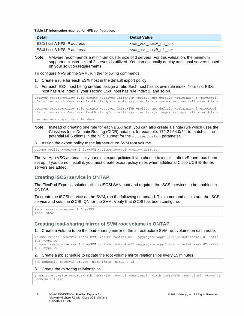
31 NVA-1154-DEPLOY: FlexPod Express for VMware vSphere 7.0 with Cisco UCS Mini and NetApp AFF/FAS
© 2021 NetApp, Inc. All Rights Reserved.
Table 16) Information required for NFS configuration.
Detail Detail Value
ESXi host A NFS IP address <var_esxi_hostA_nfs_ip>
ESXi host B NFS IP address <var_esxi_hostB_nfs_ip>
Note: VMware recommends a minimum cluster size of 3 servers. For this validation, the minimum supported cluster size of 2 servers is utilized. You can optionally deploy additional servers based on your solution requirements.
To configure NFS on the SVM, run the following commands:
1. Create a rule for each ESXi host in the default export policy.
2. For each ESXi host being created, assign a rule. Each host has its own rule index. Your first ESXi host has rule index 1, your second ESXi host has rule index 2, and so on.
vserver export-policy rule create –vserver Infra-SVM -policyname default –ruleindex 1 –protocol
nfs -clientmatch <var_esxi_hostA_nfs_ip> -rorule sys –rwrule sys -superuser sys –allow-suid true
vserver export-policy rule create –vserver Infra-SVM -policyname default –ruleindex 2 –protocol
nfs -clientmatch <var_esxi_hostB_nfs_ip> -rorule sys –rwrule sys -superuser sys –allow-suid true
vserver export-policy rule show
Note: Instead of creating one rule for each ESXi host, you can also create a single rule which uses the Classless Inter-Domain Routing (CIDR) notation, for example. 172.21.64.0/24, to match all the potential NFS clients in the NFS subnet for the -clientmatch parameter.
3. Assign the export policy to the infrastructure SVM root volume.
volume modify –vserver Infra-SVM –volume rootvol –policy default
The NetApp VSC automatically handles export policies if you choose to install it after vSphere has been
set up. If you do not install it, you must create export policy rules when additional Cisco UCS B-Series
servers are added.
Creating iSCSI service in ONTAP
The FlexPod Express solution utilizes iSCSI SAN boot and requires the iSCSI services to be enabled in
ONTAP.
To create the iSCSI service on the SVM, run the following command. This command also starts the iSCSI
service and sets the iSCSI IQN for the SVM. Verify that iSCSI has been configured.
iscsi create -vserver Infra-SVM
iscsi show
Creating load-sharing mirror of SVM root volume in ONTAP
1. Create a volume to be the load-sharing mirror of the infrastructure SVM root volume on each node.
volume create –vserver Infra-SVM –volume rootvol_m01 –aggregate aggr1_<var_clustername>_01 –size
1GB –type DP
volume create –vserver Infra-SVM –volume rootvol_m02 –aggregate aggr1_<var_clustername>_02 –size
1GB –type DP
2. Create a job schedule to update the root volume mirror relationships every 15 minutes.
job schedule interval create -name 15min -minutes 15
3. Create the mirroring relationships.
snapmirror create -source-path Infra-SVM:rootvol -destination-path Infra-SVM:rootvol_m01 -type LS
-schedule 15min
32 NVA-1154-DEPLOY: FlexPod Express for VMware vSphere 7.0 with Cisco UCS Mini and NetApp AFF/FAS
© 2021 NetApp, Inc. All Rights Reserved.
snapmirror create -source-path Infra-SVM:rootvol -destination-path Infra-SVM:rootvol_m02 -type LS
-schedule 15min
4. Initialize the mirroring relationship and verify that it has been created.
snapmirror initialize-ls-set -source-path Infra-SVM:rootvol
snapmirror show
Configure HTTPS access in ONTAP
To configure secure access to the storage controller, complete the following steps:
1. Increase the privilege level to access the certificate commands.
set -privilege diag
Do you want to continue? {y|n}: y
2. Generally, a self-signed certificate is already in place. Verify the certificate by running the following command:
security certificate show
3. For each SVM shown, the certificate common name should match the DNS FQDN of the SVM. The four default certificates should be deleted and replaced by either self-signed certificates or certificates from a certificate authority.
Note: Deleting expired certificates before creating certificates is a best practice. Run the security certificate delete command to delete expired certificates. In the following command, use TAB completion to select and delete each default certificate.
security certificate delete [TAB] …
Example: security certificate delete -vserver Infra-SVM -common-name Infra-SVM -ca Infra-SVM -
type server -serial 552429A6
4. To generate and install self-signed certificates, run the following commands as one-time commands. Generate a server certificate for the infra-SVM and the cluster SVM. Again, use TAB completion to aid in completing these commands.
security certificate create [TAB] …
Example: security certificate create -common-name infra-svm.netapp.com -type server -size 2048 -
country US -state "North Carolina" -locality "RTP" -organization "NetApp" -unit "FlexPod" -email-
addr "[email protected]" -expire-days 3650 -protocol SSL -hash-function SHA256 -vserver Infra-SVM
5. To obtain the values for the parameters required in the following step, run the security
certificate show command.
6. Enable each certificate that was just created by using the –server-enabled true and –client-
enabled false parameters. Again, use TAB completion.
security ssl modify [TAB] …
Example: security ssl modify -vserver Infra-SVM -server-enabled true -client-enabled false -ca
infra-svm.netapp.com -serial 55243646 -common-name infra-svm.netapp.com
7. Disable HTTP cluster management access.
system service web modify -external true -http-enabled false
system services firewall policy delete -policy mgmt -service http –vserver <var_clustername>
Note: It is normal for some of these commands to return an error message stating that the entry does not exist.
8. Revert to the admin privilege level and create the setup to allow the SVM to be available by the web.
set –privilege admin
vserver services web modfy –name spi|ontapi|compat –vserver * -enabled true
9. Verify that the system logs are available in a web browser.
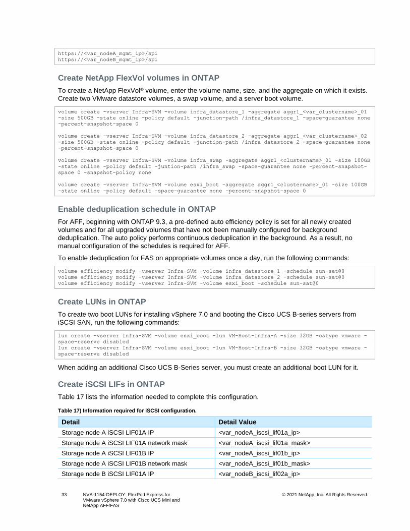
33 NVA-1154-DEPLOY: FlexPod Express for VMware vSphere 7.0 with Cisco UCS Mini and NetApp AFF/FAS
© 2021 NetApp, Inc. All Rights Reserved.
https://<var_nodeA_mgmt_ip>/spi
https://<var_nodeB_mgmt_ip>/spi
Create NetApp FlexVol volumes in ONTAP
To create a NetApp FlexVol® volume, enter the volume name, size, and the aggregate on which it exists.
Create two VMware datastore volumes, a swap volume, and a server boot volume.
volume create -vserver Infra-SVM -volume infra_datastore_1 -aggregate aggr1_<var_clustername>_01
-size 500GB -state online -policy default -junction-path /infra_datastore_1 -space-guarantee none
-percent-snapshot-space 0
volume create -vserver Infra-SVM -volume infra_datastore_2 -aggregate aggr1_<var_clustername>_02
-size 500GB -state online -policy default -junction-path /infra_datastore_2 -space-guarantee none
-percent-snapshot-space 0
volume create -vserver Infra-SVM -volume infra_swap -aggregate aggr1_<clustername>_01 -size 100GB
-state online -policy default -juntion-path /infra_swap -space-guarantee none -percent-snapshot-
space 0 -snapshot-policy none
volume create -vserver Infra-SVM -volume esxi_boot -aggregate aggr1_<clustername>_01 -size 100GB
-state online -policy default -space-guarantee none -percent-snapshot-space 0
Enable deduplication schedule in ONTAP
For AFF, beginning with ONTAP 9.3, a pre-defined auto efficiency policy is set for all newly created
volumes and for all upgraded volumes that have not been manually configured for background
deduplication. The auto policy performs continuous deduplication in the background. As a result, no
manual configuration of the schedules is required for AFF.
To enable deduplication for FAS on appropriate volumes once a day, run the following commands:
volume efficiency modify -vserver Infra-SVM -volume infra_datastore_1 -schedule sun-sat@0
volume efficiency modify -vserver Infra-SVM -volume infra_datastore_2 -schedule sun-sat@0
volume efficiency modify -vserver Infra-SVM -volume esxi_boot -schedule sun-sat@0
Create LUNs in ONTAP
To create two boot LUNs for installing vSphere 7.0 and booting the Cisco UCS B-series servers from
iSCSI SAN, run the following commands:
lun create -vserver Infra-SVM -volume esxi_boot -lun VM-Host-Infra-A -size 32GB -ostype vmware -
space-reserve disabled
lun create -vserver Infra-SVM -volume esxi_boot -lun VM-Host-Infra-B -size 32GB -ostype vmware -
space-reserve disabled
When adding an additional Cisco UCS B-Series server, you must create an additional boot LUN for it.
Create iSCSI LIFs in ONTAP
Table 17 lists the information needed to complete this configuration.
Table 17) Information required for iSCSI configuration.
Detail Detail Value
Storage node A iSCSI LIF01A IP <var_nodeA_iscsi_lif01a_ip>
Storage node A iSCSI LIF01A network mask <var_nodeA_iscsi_lif01a_mask>
Storage node A iSCSI LIF01B IP <var_nodeA_iscsi_lif01b_ip>
Storage node A iSCSI LIF01B network mask <var_nodeA_iscsi_lif01b_mask>
Storage node B iSCSI LIF01A IP <var_nodeB_iscsi_lif02a_ip>
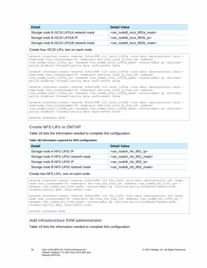
34 NVA-1154-DEPLOY: FlexPod Express for VMware vSphere 7.0 with Cisco UCS Mini and NetApp AFF/FAS
© 2021 NetApp, Inc. All Rights Reserved.
Detail Detail Value
Storage node B iSCSI LIF01A network mask <var_nodeB_iscsi_lif02a_mask>
Storage node B iSCSI LIF01B IP <var_nodeB_iscsi_lif02b_ip>
Storage node B iSCSI LIF01B network mask <var_nodeB_iscsi_lif02b_mask>
Create four iSCSI LIFs, two on each node.
network interface create -vserver Infra-SVM -lif iscsi_lif01a -role data -data-protocol iscsi -
home-node <var_clustername>-01 -home-port e0c-<var_iscsi_A_vlan_id> -address
<var_nodeA_iscsi_lif01a_ip> -netmask <var_nodeA_iscsi_lif01a_mask> -status-admin up -failover-
policy disabled -firewall-policy data -auto-revert false
network interface create -vserver Infra-SVM -lif iscsi_lif01b -role data -data-protocol iscsi -
home-node <var_clustername>-01 -home-port e0d-<var_iscsi_B_vlan_id> -address
<var_nodeA_iscsi_lif01b_ip> -netmask <var_nodeA_iscsi_lif01b_mask> -status-admin up -failover-
policy disabled -firewall-policy data -auto-revert false
network interface create -vserver Infra-SVM -lif iscsi_lif02a -role data -data-protocol iscsi -
home-node <var_clustername>-02 -home-port e0c-<var_iscsi_A_vlan_id> -address
<var_nodeB_iscsi_lif02a_ip> -netmask <var_nodeA_iscsi_lif02a_mask> -status-admin up -failover-
policy disabled -firewall-policy data -auto-revert false
network interface create -vserver Infra-SVM -lif iscsi_lif02b -role data -data-protocol iscsi -
home-node <var_clustername>-02 -home-port e0d-<var_iscsi_B_vlan_id> -address
<var_nodeB_iscsi_lif02b_ip> -netmask <var_nodeA_iscsi_lif02b_mask> -status-admin up -failover-
policy disabled -firewall-policy data -auto-revert false
network interface show
Create NFS LIFs in ONTAP
Table 18 lists the information needed to complete this configuration.
Table 18) Information required for NFS configuration.
Detail Detail Value
Storage node A NFS LIF01 IP <var_nodeA_nfs_lif01_ip>
Storage node A NFS LIF01 network mask <var_nodeA_nfs_lif01_mask>
Storage node B NFS LIF02 IP <var_nodeB_nfs_lif02_ip>
Storage node B NFS LIF02 network mask <var_nodeB_nfs_lif02_mask>
Create two NFS LIFs, one on each node.
network interface create -vserver Infra-SVM -lif nfs_lif01 -role data -data-protocol nfs -home-
node <var_clusername>-01 -home-port e0c-<var_nfs_vlan_id> –address <var_nodeA_nfs_lif01_ip> -
netmask <var_nodeA_nfs_lif01_mask> -status-admin up –failover-policy broadcast-domain-wide –
firewall-policy data –auto-revert true
network interface create -vserver Infra-SVM -lif nfs_lif02 -role data -data-protocol nfs -home-
node <var_clustername>-02 -home-port e0c-<var_nfs_vlan_id> –address <var_nodeB_nfs_lif02_ip> -
netmask <var_nodeB_nfs_lif02_mask> -status-admin up –failover-policy broadcast-domain-wide –
firewall-policy data –auto-revert true
network interface show
Add infrastructure SVM administrator
Table 19 lists the information needed to complete this configuration.
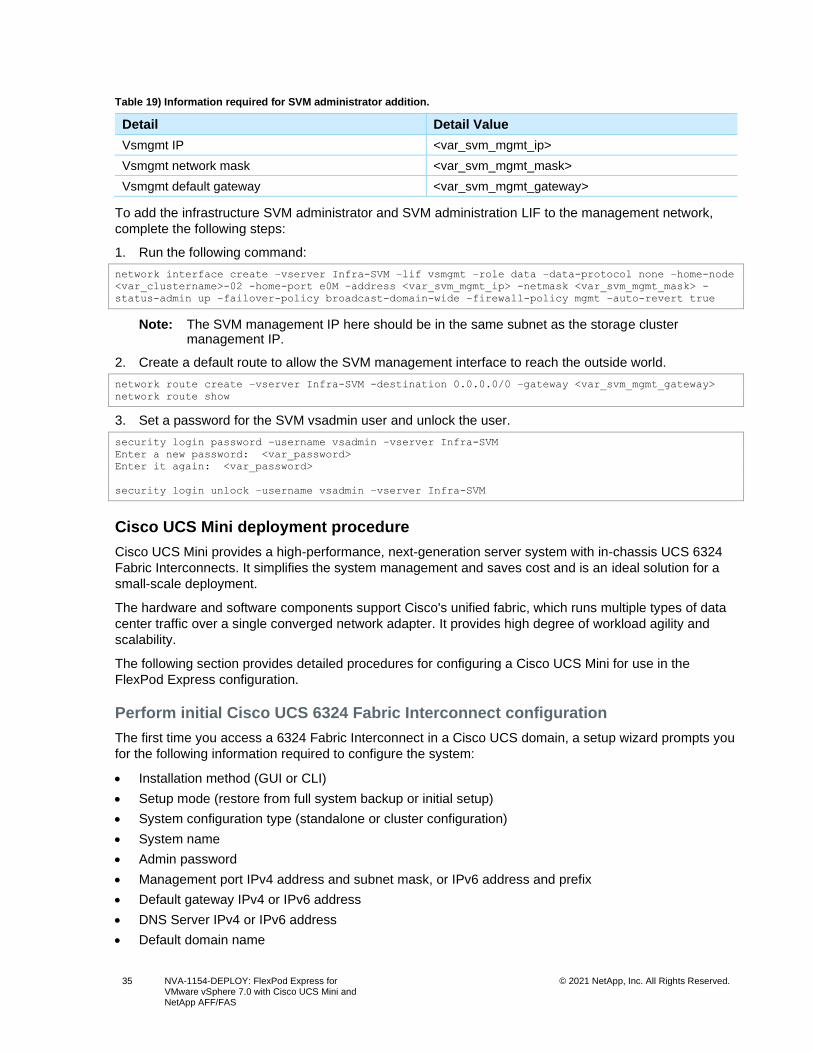
35 NVA-1154-DEPLOY: FlexPod Express for VMware vSphere 7.0 with Cisco UCS Mini and NetApp AFF/FAS
© 2021 NetApp, Inc. All Rights Reserved.
Table 19) Information required for SVM administrator addition.
Detail Detail Value
Vsmgmt IP <var_svm_mgmt_ip>
Vsmgmt network mask <var_svm_mgmt_mask>
Vsmgmt default gateway <var_svm_mgmt_gateway>
To add the infrastructure SVM administrator and SVM administration LIF to the management network,
complete the following steps:
1. Run the following command:
network interface create –vserver Infra-SVM –lif vsmgmt –role data –data-protocol none –home-node
<var_clustername>-02 -home-port e0M –address <var_svm_mgmt_ip> -netmask <var_svm_mgmt_mask> -
status-admin up –failover-policy broadcast-domain-wide –firewall-policy mgmt –auto-revert true
Note: The SVM management IP here should be in the same subnet as the storage cluster management IP.
2. Create a default route to allow the SVM management interface to reach the outside world.
network route create –vserver Infra-SVM -destination 0.0.0.0/0 –gateway <var_svm_mgmt_gateway>
network route show
3. Set a password for the SVM vsadmin user and unlock the user.
security login password –username vsadmin –vserver Infra-SVM
Enter a new password: <var_password>
Enter it again: <var_password>
security login unlock –username vsadmin –vserver Infra-SVM
Cisco UCS Mini deployment procedure
Cisco UCS Mini provides a high-performance, next-generation server system with in-chassis UCS 6324
Fabric Interconnects. It simplifies the system management and saves cost and is an ideal solution for a
small-scale deployment.
The hardware and software components support Cisco's unified fabric, which runs multiple types of data
center traffic over a single converged network adapter. It provides high degree of workload agility and
scalability.
The following section provides detailed procedures for configuring a Cisco UCS Mini for use in the
FlexPod Express configuration.
Perform initial Cisco UCS 6324 Fabric Interconnect configuration
The first time you access a 6324 Fabric Interconnect in a Cisco UCS domain, a setup wizard prompts you
for the following information required to configure the system:
• Installation method (GUI or CLI)
• Setup mode (restore from full system backup or initial setup)
• System configuration type (standalone or cluster configuration)
• System name
• Admin password
• Management port IPv4 address and subnet mask, or IPv6 address and prefix
• Default gateway IPv4 or IPv6 address
• DNS Server IPv4 or IPv6 address
• Default domain name
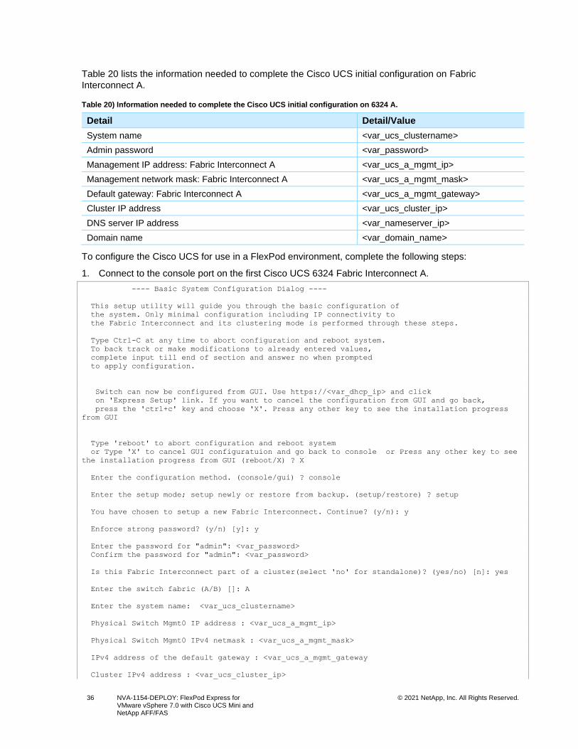
36 NVA-1154-DEPLOY: FlexPod Express for VMware vSphere 7.0 with Cisco UCS Mini and NetApp AFF/FAS
© 2021 NetApp, Inc. All Rights Reserved.
Table 20 lists the information needed to complete the Cisco UCS initial configuration on Fabric
Interconnect A.
Table 20) Information needed to complete the Cisco UCS initial configuration on 6324 A.
Detail Detail/Value
System name <var_ucs_clustername>
Admin password <var_password>
Management IP address: Fabric Interconnect A <var_ucs_a_mgmt_ip>
Management network mask: Fabric Interconnect A <var_ucs_a_mgmt_mask>
Default gateway: Fabric Interconnect A <var_ucs_a_mgmt_gateway>
Cluster IP address <var_ucs_cluster_ip>
DNS server IP address <var_nameserver_ip>
Domain name <var_domain_name>
To configure the Cisco UCS for use in a FlexPod environment, complete the following steps:
1. Connect to the console port on the first Cisco UCS 6324 Fabric Interconnect A.
---- Basic System Configuration Dialog ----
This setup utility will guide you through the basic configuration of
the system. Only minimal configuration including IP connectivity to
the Fabric Interconnect and its clustering mode is performed through these steps.
Type Ctrl-C at any time to abort configuration and reboot system.
To back track or make modifications to already entered values,
complete input till end of section and answer no when prompted
to apply configuration.
Switch can now be configured from GUI. Use https://<var_dhcp_ip> and click
on 'Express Setup' link. If you want to cancel the configuration from GUI and go back,
press the 'ctrl+c' key and choose 'X'. Press any other key to see the installation progress
from GUI
Type 'reboot' to abort configuration and reboot system
or Type 'X' to cancel GUI configuratuion and go back to console or Press any other key to see
the installation progress from GUI (reboot/X) ? X
Enter the configuration method. (console/gui) ? console
Enter the setup mode; setup newly or restore from backup. (setup/restore) ? setup
You have chosen to setup a new Fabric Interconnect. Continue? (y/n): y
Enforce strong password? (y/n) [y]: y
Enter the password for "admin": <var_password>
Confirm the password for "admin": <var_password>
Is this Fabric Interconnect part of a cluster(select 'no' for standalone)? (yes/no) [n]: yes
Enter the switch fabric (A/B) []: A
Enter the system name: <var_ucs_clustername>
Physical Switch Mgmt0 IP address : <var_ucs_a_mgmt_ip>
Physical Switch Mgmt0 IPv4 netmask : <var_ucs_a_mgmt_mask>
IPv4 address of the default gateway : <var_ucs_a_mgmt_gateway
Cluster IPv4 address : <var_ucs_cluster_ip>
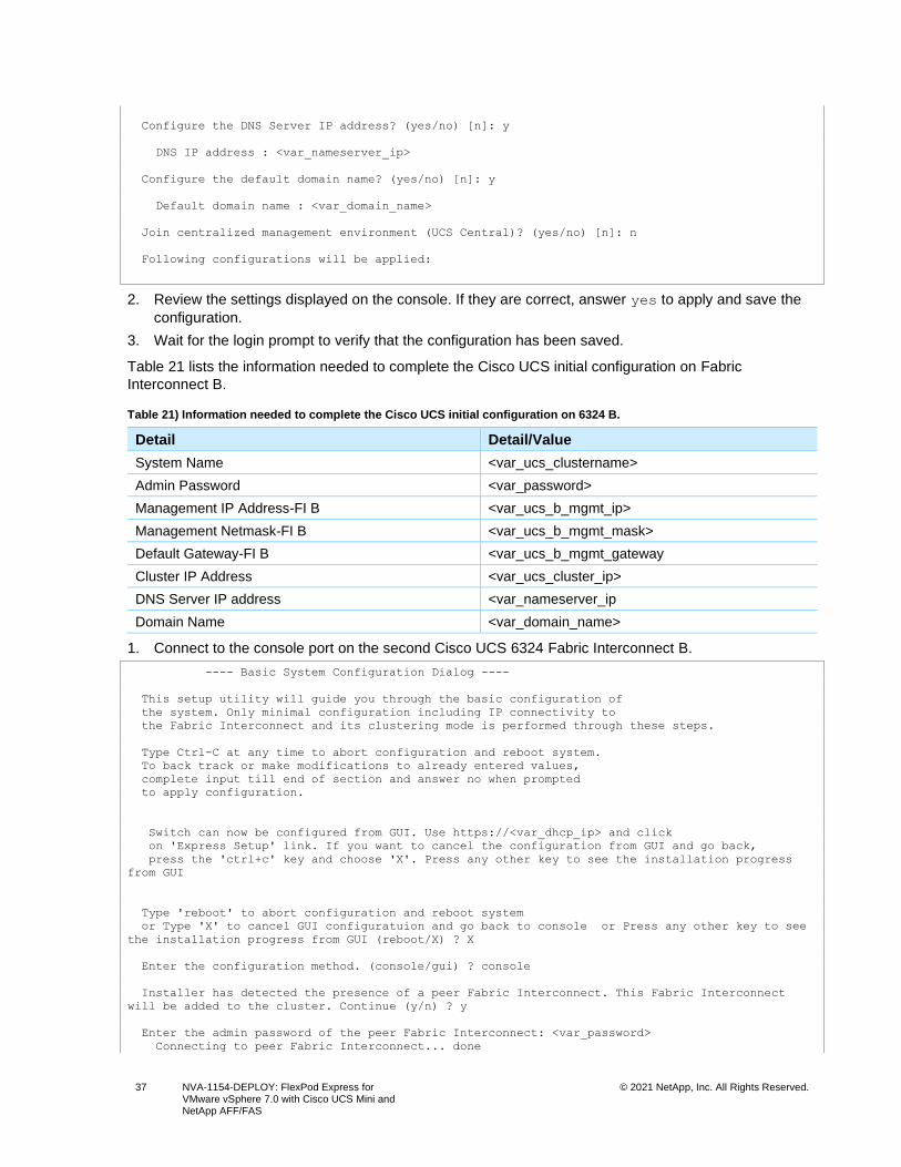
37 NVA-1154-DEPLOY: FlexPod Express for VMware vSphere 7.0 with Cisco UCS Mini and NetApp AFF/FAS
© 2021 NetApp, Inc. All Rights Reserved.
Configure the DNS Server IP address? (yes/no) [n]: y
DNS IP address : <var_nameserver_ip>
Configure the default domain name? (yes/no) [n]: y
Default domain name : <var_domain_name>
Join centralized management environment (UCS Central)? (yes/no) [n]: n
Following configurations will be applied:
2. Review the settings displayed on the console. If they are correct, answer yes to apply and save the
configuration.
3. Wait for the login prompt to verify that the configuration has been saved.
Table 21 lists the information needed to complete the Cisco UCS initial configuration on Fabric
Interconnect B.
Table 21) Information needed to complete the Cisco UCS initial configuration on 6324 B.
Detail Detail/Value
System Name <var_ucs_clustername>
Admin Password <var_password>
Management IP Address-FI B <var_ucs_b_mgmt_ip>
Management Netmask-FI B <var_ucs_b_mgmt_mask>
Default Gateway-FI B <var_ucs_b_mgmt_gateway
Cluster IP Address <var_ucs_cluster_ip>
DNS Server IP address <var_nameserver_ip
Domain Name <var_domain_name>
1. Connect to the console port on the second Cisco UCS 6324 Fabric Interconnect B.
---- Basic System Configuration Dialog ----
This setup utility will guide you through the basic configuration of
the system. Only minimal configuration including IP connectivity to
the Fabric Interconnect and its clustering mode is performed through these steps.
Type Ctrl-C at any time to abort configuration and reboot system.
To back track or make modifications to already entered values,
complete input till end of section and answer no when prompted
to apply configuration.
Switch can now be configured from GUI. Use https://<var_dhcp_ip> and click
on 'Express Setup' link. If you want to cancel the configuration from GUI and go back,
press the 'ctrl+c' key and choose 'X'. Press any other key to see the installation progress
from GUI
Type 'reboot' to abort configuration and reboot system
or Type 'X' to cancel GUI configuratuion and go back to console or Press any other key to see
the installation progress from GUI (reboot/X) ? X
Enter the configuration method. (console/gui) ? console
Installer has detected the presence of a peer Fabric Interconnect. This Fabric Interconnect
will be added to the cluster. Continue (y/n) ? y
Enter the admin password of the peer Fabric Interconnect: <var_password>
Connecting to peer Fabric Interconnect... done
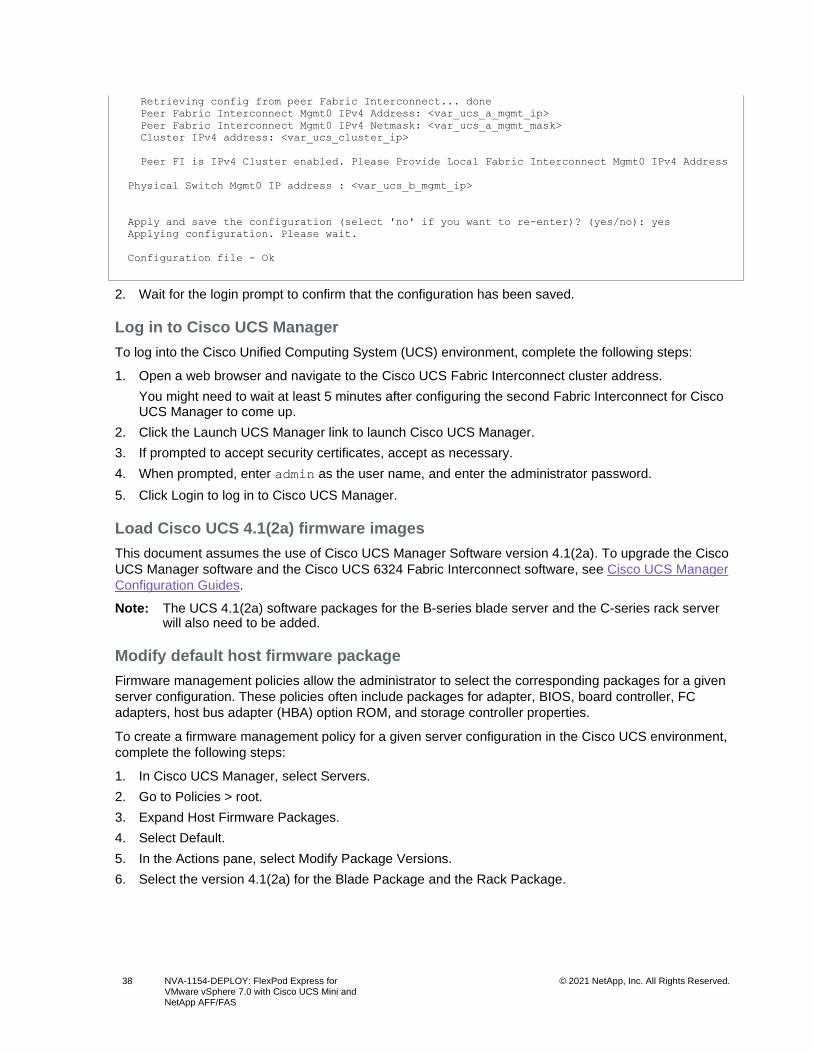
38 NVA-1154-DEPLOY: FlexPod Express for VMware vSphere 7.0 with Cisco UCS Mini and NetApp AFF/FAS
© 2021 NetApp, Inc. All Rights Reserved.
Retrieving config from peer Fabric Interconnect... done
Peer Fabric Interconnect Mgmt0 IPv4 Address: <var_ucs_a_mgmt_ip>
Peer Fabric Interconnect Mgmt0 IPv4 Netmask: <var_ucs_a_mgmt_mask>
Cluster IPv4 address: <var_ucs_cluster_ip>
Peer FI is IPv4 Cluster enabled. Please Provide Local Fabric Interconnect Mgmt0 IPv4 Address
Physical Switch Mgmt0 IP address : <var_ucs_b_mgmt_ip>
Apply and save the configuration (select 'no' if you want to re-enter)? (yes/no): yes
Applying configuration. Please wait.
Configuration file - Ok
2. Wait for the login prompt to confirm that the configuration has been saved.
Log in to Cisco UCS Manager
To log into the Cisco Unified Computing System (UCS) environment, complete the following steps:
1. Open a web browser and navigate to the Cisco UCS Fabric Interconnect cluster address.
You might need to wait at least 5 minutes after configuring the second Fabric Interconnect for Cisco UCS Manager to come up.
2. Click the Launch UCS Manager link to launch Cisco UCS Manager.
3. If prompted to accept security certificates, accept as necessary.
4. When prompted, enter admin as the user name, and enter the administrator password.
5. Click Login to log in to Cisco UCS Manager.
Load Cisco UCS 4.1(2a) firmware images
This document assumes the use of Cisco UCS Manager Software version 4.1(2a). To upgrade the Cisco
UCS Manager software and the Cisco UCS 6324 Fabric Interconnect software, see Cisco UCS Manager
Configuration Guides.
Note: The UCS 4.1(2a) software packages for the B-series blade server and the C-series rack server will also need to be added.
Modify default host firmware package
Firmware management policies allow the administrator to select the corresponding packages for a given
server configuration. These policies often include packages for adapter, BIOS, board controller, FC
adapters, host bus adapter (HBA) option ROM, and storage controller properties.
To create a firmware management policy for a given server configuration in the Cisco UCS environment,
complete the following steps:
1. In Cisco UCS Manager, select Servers.
2. Go to Policies > root.
3. Expand Host Firmware Packages.
4. Select Default.
5. In the Actions pane, select Modify Package Versions.
6. Select the version 4.1(2a) for the Blade Package and the Rack Package.
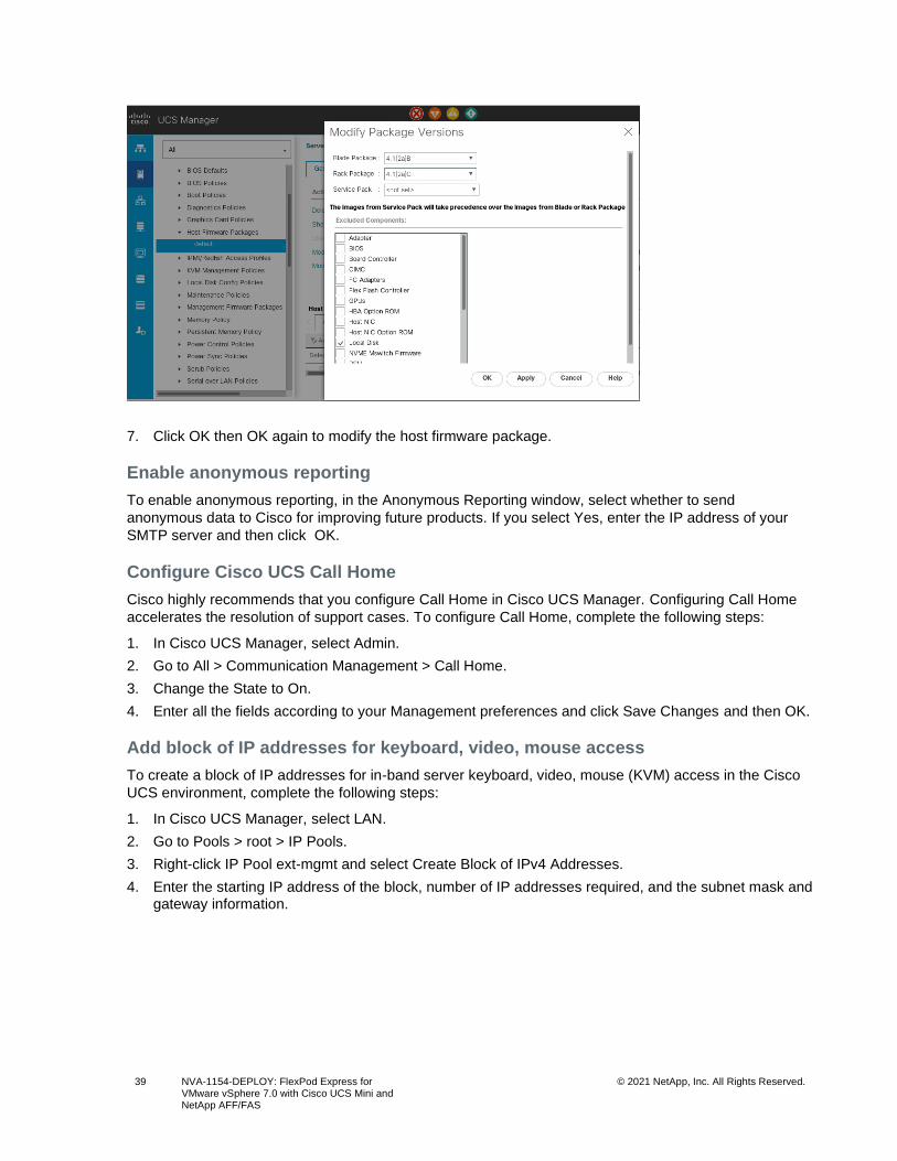
39 NVA-1154-DEPLOY: FlexPod Express for VMware vSphere 7.0 with Cisco UCS Mini and NetApp AFF/FAS
© 2021 NetApp, Inc. All Rights Reserved.
7. Click OK then OK again to modify the host firmware package.
Enable anonymous reporting
To enable anonymous reporting, in the Anonymous Reporting window, select whether to send
anonymous data to Cisco for improving future products. If you select Yes, enter the IP address of your
SMTP server and then click OK.
Configure Cisco UCS Call Home
Cisco highly recommends that you configure Call Home in Cisco UCS Manager. Configuring Call Home
accelerates the resolution of support cases. To configure Call Home, complete the following steps:
1. In Cisco UCS Manager, select Admin.
2. Go to All > Communication Management > Call Home.
3. Change the State to On.
4. Enter all the fields according to your Management preferences and click Save Changes and then OK.
Add block of IP addresses for keyboard, video, mouse access
To create a block of IP addresses for in-band server keyboard, video, mouse (KVM) access in the Cisco
UCS environment, complete the following steps:
1. In Cisco UCS Manager, select LAN.
2. Go to Pools > root > IP Pools.
3. Right-click IP Pool ext-mgmt and select Create Block of IPv4 Addresses.
4. Enter the starting IP address of the block, number of IP addresses required, and the subnet mask and gateway information.
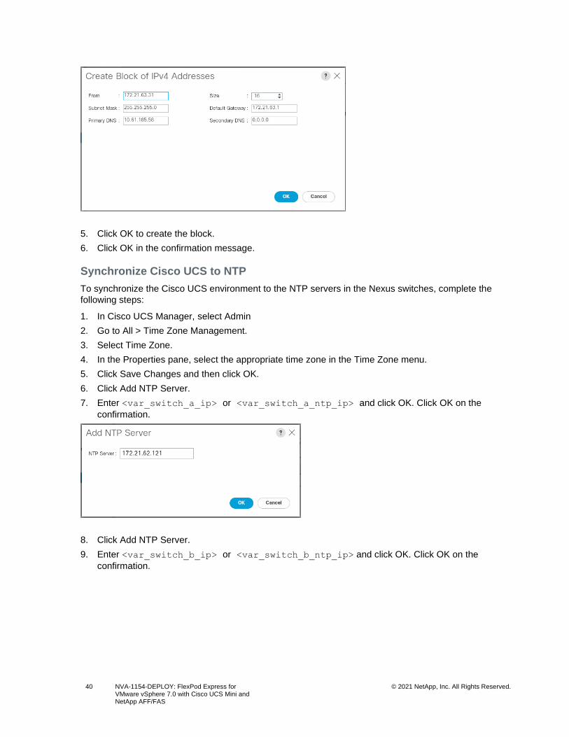
40 NVA-1154-DEPLOY: FlexPod Express for VMware vSphere 7.0 with Cisco UCS Mini and NetApp AFF/FAS
© 2021 NetApp, Inc. All Rights Reserved.
5. Click OK to create the block.
6. Click OK in the confirmation message.
Synchronize Cisco UCS to NTP
To synchronize the Cisco UCS environment to the NTP servers in the Nexus switches, complete the
following steps:
1. In Cisco UCS Manager, select Admin
2. Go to All > Time Zone Management.
3. Select Time Zone.
4. In the Properties pane, select the appropriate time zone in the Time Zone menu.
5. Click Save Changes and then click OK.
6. Click Add NTP Server.
7. Enter <var_switch_a_ip> or <var_switch_a_ntp_ip> and click OK. Click OK on the
confirmation.
8. Click Add NTP Server.
9. Enter <var_switch_b_ip> or <var_switch_b_ntp_ip> and click OK. Click OK on the
confirmation.
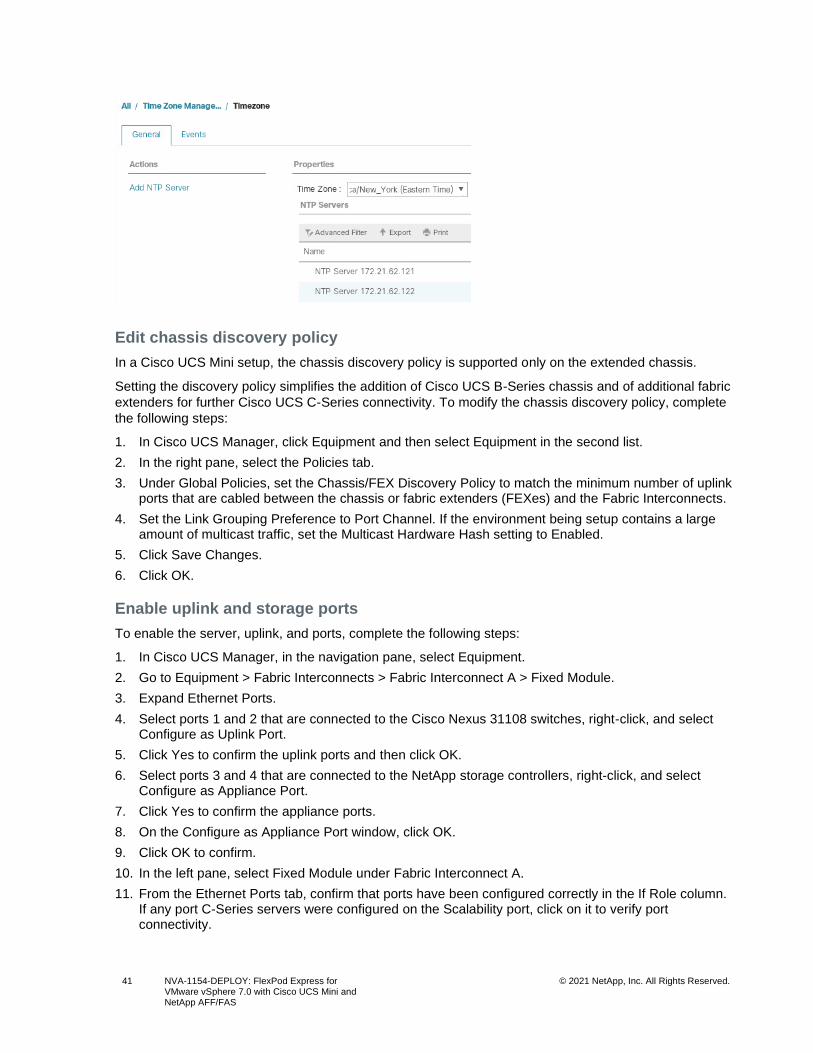
41 NVA-1154-DEPLOY: FlexPod Express for VMware vSphere 7.0 with Cisco UCS Mini and NetApp AFF/FAS
© 2021 NetApp, Inc. All Rights Reserved.
Edit chassis discovery policy
In a Cisco UCS Mini setup, the chassis discovery policy is supported only on the extended chassis.
Setting the discovery policy simplifies the addition of Cisco UCS B-Series chassis and of additional fabric
extenders for further Cisco UCS C-Series connectivity. To modify the chassis discovery policy, complete
the following steps:
1. In Cisco UCS Manager, click Equipment and then select Equipment in the second list.
2. In the right pane, select the Policies tab.
3. Under Global Policies, set the Chassis/FEX Discovery Policy to match the minimum number of uplink ports that are cabled between the chassis or fabric extenders (FEXes) and the Fabric Interconnects.
4. Set the Link Grouping Preference to Port Channel. If the environment being setup contains a large amount of multicast traffic, set the Multicast Hardware Hash setting to Enabled.
5. Click Save Changes.
6. Click OK.
Enable uplink and storage ports
To enable the server, uplink, and ports, complete the following steps:
1. In Cisco UCS Manager, in the navigation pane, select Equipment.
2. Go to Equipment > Fabric Interconnects > Fabric Interconnect A > Fixed Module.
3. Expand Ethernet Ports.
4. Select ports 1 and 2 that are connected to the Cisco Nexus 31108 switches, right-click, and select Configure as Uplink Port.
5. Click Yes to confirm the uplink ports and then click OK.
6. Select ports 3 and 4 that are connected to the NetApp storage controllers, right-click, and select Configure as Appliance Port.
7. Click Yes to confirm the appliance ports.
8. On the Configure as Appliance Port window, click OK.
9. Click OK to confirm.
10. In the left pane, select Fixed Module under Fabric Interconnect A.
11. From the Ethernet Ports tab, confirm that ports have been configured correctly in the If Role column. If any port C-Series servers were configured on the Scalability port, click on it to verify port connectivity.
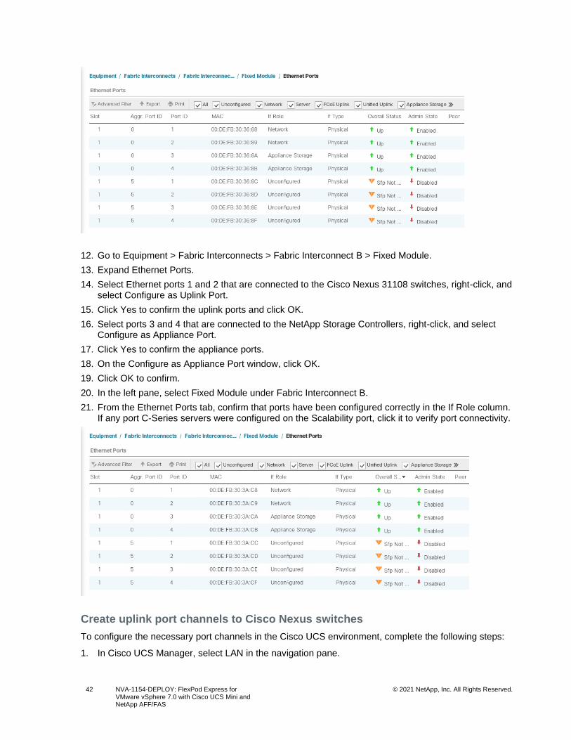
42 NVA-1154-DEPLOY: FlexPod Express for VMware vSphere 7.0 with Cisco UCS Mini and NetApp AFF/FAS
© 2021 NetApp, Inc. All Rights Reserved.
12. Go to Equipment > Fabric Interconnects > Fabric Interconnect B > Fixed Module.
13. Expand Ethernet Ports.
14. Select Ethernet ports 1 and 2 that are connected to the Cisco Nexus 31108 switches, right-click, and select Configure as Uplink Port.
15. Click Yes to confirm the uplink ports and click OK.
16. Select ports 3 and 4 that are connected to the NetApp Storage Controllers, right-click, and select Configure as Appliance Port.
17. Click Yes to confirm the appliance ports.
18. On the Configure as Appliance Port window, click OK.
19. Click OK to confirm.
20. In the left pane, select Fixed Module under Fabric Interconnect B.
21. From the Ethernet Ports tab, confirm that ports have been configured correctly in the If Role column. If any port C-Series servers were configured on the Scalability port, click it to verify port connectivity.
Create uplink port channels to Cisco Nexus switches
To configure the necessary port channels in the Cisco UCS environment, complete the following steps:
1. In Cisco UCS Manager, select LAN in the navigation pane.
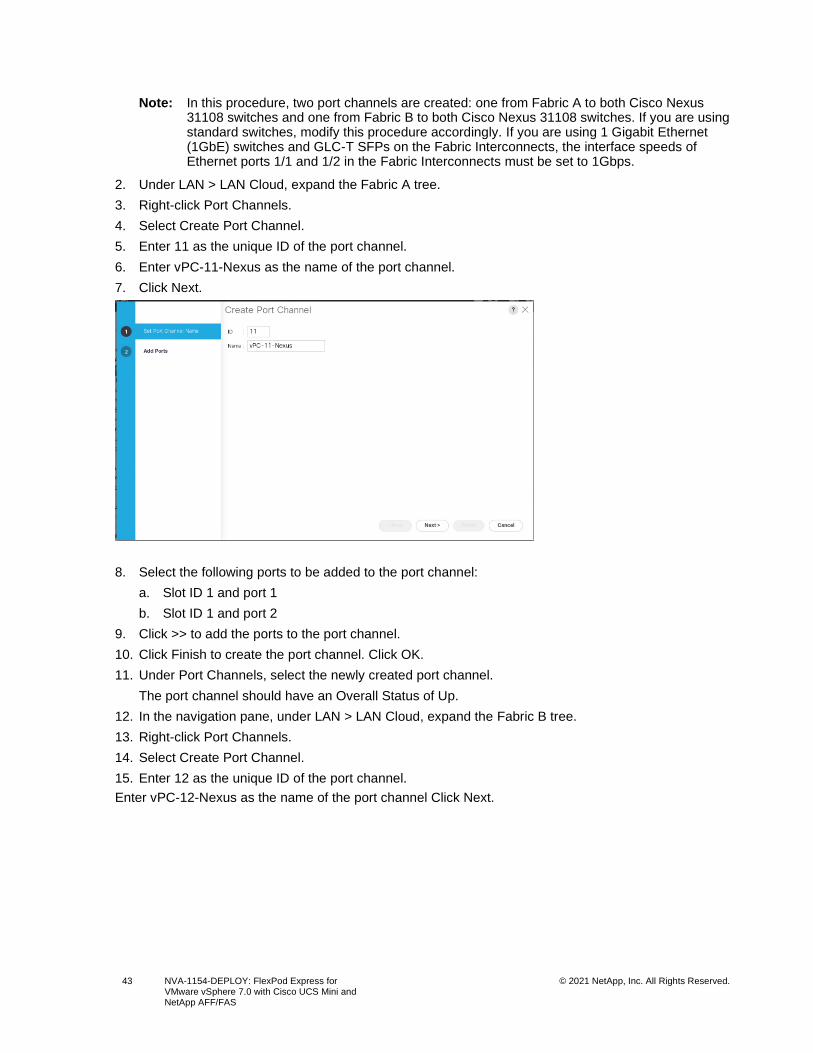
43 NVA-1154-DEPLOY: FlexPod Express for VMware vSphere 7.0 with Cisco UCS Mini and NetApp AFF/FAS
© 2021 NetApp, Inc. All Rights Reserved.
Note: In this procedure, two port channels are created: one from Fabric A to both Cisco Nexus 31108 switches and one from Fabric B to both Cisco Nexus 31108 switches. If you are using standard switches, modify this procedure accordingly. If you are using 1 Gigabit Ethernet (1GbE) switches and GLC-T SFPs on the Fabric Interconnects, the interface speeds of Ethernet ports 1/1 and 1/2 in the Fabric Interconnects must be set to 1Gbps.
2. Under LAN > LAN Cloud, expand the Fabric A tree.
3. Right-click Port Channels.
4. Select Create Port Channel.
5. Enter 11 as the unique ID of the port channel.
6. Enter vPC-11-Nexus as the name of the port channel.
7. Click Next.
8. Select the following ports to be added to the port channel:
a. Slot ID 1 and port 1
b. Slot ID 1 and port 2
9. Click >> to add the ports to the port channel.
10. Click Finish to create the port channel. Click OK.
11. Under Port Channels, select the newly created port channel.
The port channel should have an Overall Status of Up.
12. In the navigation pane, under LAN > LAN Cloud, expand the Fabric B tree.
13. Right-click Port Channels.
14. Select Create Port Channel.
15. Enter 12 as the unique ID of the port channel.
Enter vPC-12-Nexus as the name of the port channel Click Next.
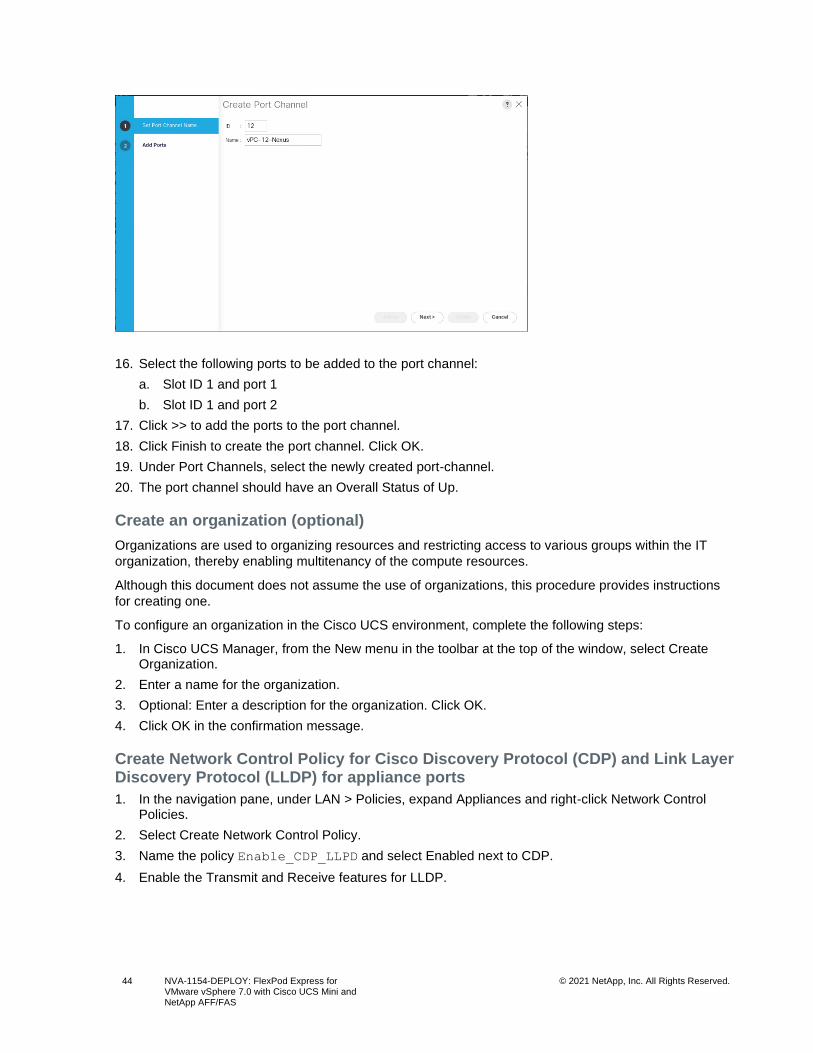
44 NVA-1154-DEPLOY: FlexPod Express for VMware vSphere 7.0 with Cisco UCS Mini and NetApp AFF/FAS
© 2021 NetApp, Inc. All Rights Reserved.
16. Select the following ports to be added to the port channel:
a. Slot ID 1 and port 1
b. Slot ID 1 and port 2
17. Click >> to add the ports to the port channel.
18. Click Finish to create the port channel. Click OK.
19. Under Port Channels, select the newly created port-channel.
20. The port channel should have an Overall Status of Up.
Create an organization (optional)
Organizations are used to organizing resources and restricting access to various groups within the IT
organization, thereby enabling multitenancy of the compute resources.
Although this document does not assume the use of organizations, this procedure provides instructions
for creating one.
To configure an organization in the Cisco UCS environment, complete the following steps:
1. In Cisco UCS Manager, from the New menu in the toolbar at the top of the window, select Create Organization.
2. Enter a name for the organization.
3. Optional: Enter a description for the organization. Click OK.
4. Click OK in the confirmation message.
Create Network Control Policy for Cisco Discovery Protocol (CDP) and Link Layer Discovery Protocol (LLDP) for appliance ports
1. In the navigation pane, under LAN > Policies, expand Appliances and right-click Network Control Policies.
2. Select Create Network Control Policy.
3. Name the policy Enable_CDP_LLPD and select Enabled next to CDP.
4. Enable the Transmit and Receive features for LLDP.
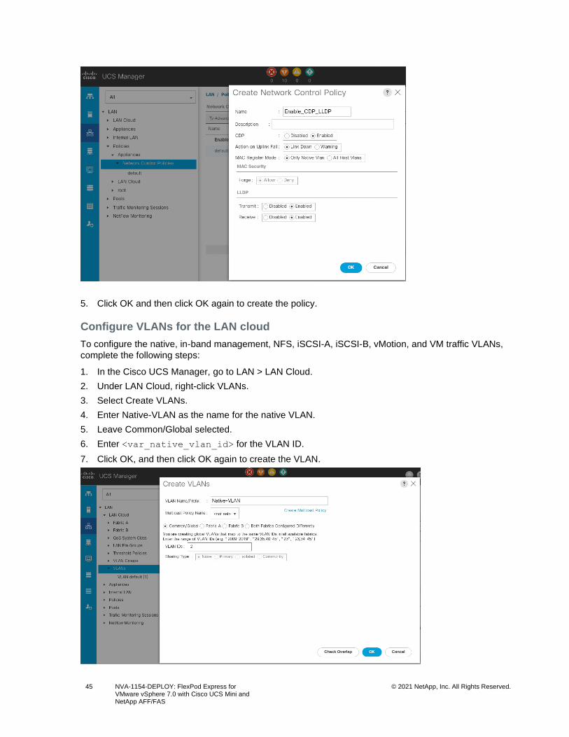
45 NVA-1154-DEPLOY: FlexPod Express for VMware vSphere 7.0 with Cisco UCS Mini and NetApp AFF/FAS
© 2021 NetApp, Inc. All Rights Reserved.
5. Click OK and then click OK again to create the policy.
Configure VLANs for the LAN cloud
To configure the native, in-band management, NFS, iSCSI-A, iSCSI-B, vMotion, and VM traffic VLANs,
complete the following steps:
1. In the Cisco UCS Manager, go to LAN > LAN Cloud.
2. Under LAN Cloud, right-click VLANs.
3. Select Create VLANs.
4. Enter Native-VLAN as the name for the native VLAN.
5. Leave Common/Global selected.
6. Enter <var_native_vlan_id> for the VLAN ID.
7. Click OK, and then click OK again to create the VLAN.
46 NVA-1154-DEPLOY: FlexPod Express for VMware vSphere 7.0 with Cisco UCS Mini and NetApp AFF/FAS
© 2021 NetApp, Inc. All Rights Reserved.
8. Right-click VLANs under LAN Cloud.
9. Select Create VLANs.
10. Enter IB-MGMT-VLAN as the name for the infrastructure in-band management VLAN.
11. Leave Common/Global selected.
12. Enter <var_ib_mgmt_vlan_id> for the VLAN ID.
13. Click OK, and then click OK again to create the VLAN.
14. Right-click VLANs under LAN Cloud.
15. Select Create VLANs.
16. Enter NFS-VLAN as the name for the NFS VLAN.
17. Leave Common/Global selected.
18. Enter <var_nfs_vlan_id> for the VLAN ID.
19. Click OK, and then click OK again to create the VLAN.
20. Right-click VLANs under LAN Cloud.
21. Select Create VLANs.
22. Enter iSCSI-A-VLAN as the name for the iSCSI-A VLAN.
23. Leave Common/Global selected.
24. Enter <var_iscsi_a_vlan_id> for the VLAN ID.
25. Click OK, and then click OK again to create the VLAN.
26. Right-click VLANs under LAN Cloud.
27. Select Create VLANs.
28. Enter iSCSI-B-VLAN as the name for the iSCSI-B VLAN.
29. Leave Common/Global selected.
30. Enter <var_iscsi_b_vlan_id> for the VLAN ID.
31. Click OK, and then click OK again to create the VLAN.
32. Right-click VLANs under LAN Cloud.
33. Select Create VLANs.
34. Enter vMotion-VLAN as the name for the infrastructure vMotion VLAN.
35. Leave Common/Global selected.
36. Enter <var_vmotion_vlan_id> for the VLAN ID.
37. Click OK, and then click OK again to create the VLAN.
38. Right-click VLANs under LAN Cloud.
39. Select Create VLANs.
40. Enter VMTraffic-VLAN as the name for the infrastructure VM traffic VLAN.
41. Leave Common/Global selected.
42. Enter <var_vmtraffic_vlan_id> for the VLAN ID.
43. Click OK, and then click OK again to create the VLAN.
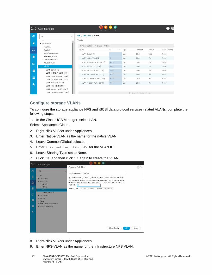
47 NVA-1154-DEPLOY: FlexPod Express for VMware vSphere 7.0 with Cisco UCS Mini and NetApp AFF/FAS
© 2021 NetApp, Inc. All Rights Reserved.
Configure storage VLANs
To configure the storage appliance NFS and iSCSI data protocol services related VLANs, complete the
following steps:
1. In the Cisco UCS Manager, select LAN.
Select Appliances Cloud.
2. Right-click VLANs under Appliances.
3. Enter Native-VLAN as the name for the native VLAN.
4. Leave Common/Global selected.
5. Enter <var_native_vlan_id> for the VLAN ID.
6. Leave Sharing Type set to None.
7. Click OK, and then click OK again to create the VLAN.
8. Right-click VLANs under Appliances.
9. Enter NFS-VLAN as the name for the Infrastructure NFS VLAN.
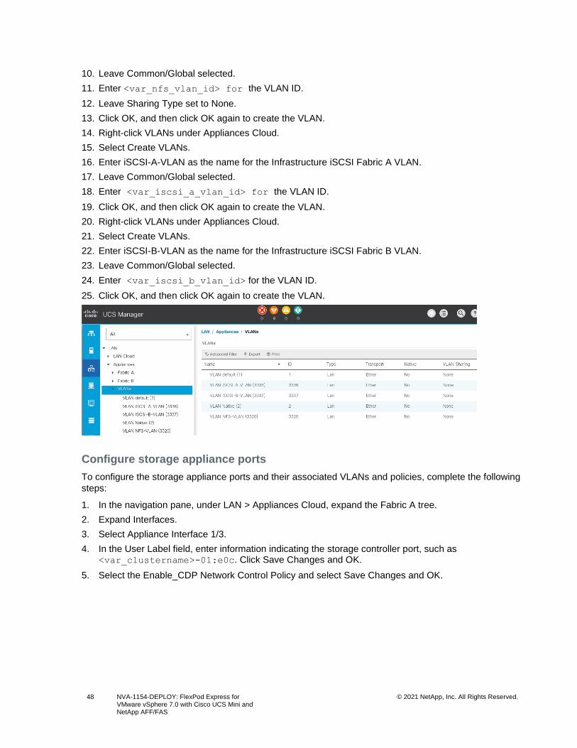
48 NVA-1154-DEPLOY: FlexPod Express for VMware vSphere 7.0 with Cisco UCS Mini and NetApp AFF/FAS
© 2021 NetApp, Inc. All Rights Reserved.
10. Leave Common/Global selected.
11. Enter <var_nfs_vlan_id> for the VLAN ID.
12. Leave Sharing Type set to None.
13. Click OK, and then click OK again to create the VLAN.
14. Right-click VLANs under Appliances Cloud.
15. Select Create VLANs.
16. Enter iSCSI-A-VLAN as the name for the Infrastructure iSCSI Fabric A VLAN.
17. Leave Common/Global selected.
18. Enter <var_iscsi_a_vlan_id> for the VLAN ID.
19. Click OK, and then click OK again to create the VLAN.
20. Right-click VLANs under Appliances Cloud.
21. Select Create VLANs.
22. Enter iSCSI-B-VLAN as the name for the Infrastructure iSCSI Fabric B VLAN.
23. Leave Common/Global selected.
24. Enter <var_iscsi_b_vlan_id> for the VLAN ID.
25. Click OK, and then click OK again to create the VLAN.
Configure storage appliance ports
To configure the storage appliance ports and their associated VLANs and policies, complete the following
steps:
1. In the navigation pane, under LAN > Appliances Cloud, expand the Fabric A tree.
2. Expand Interfaces.
3. Select Appliance Interface 1/3.
4. In the User Label field, enter information indicating the storage controller port, such as <var_clustername>-01:e0c. Click Save Changes and OK.
5. Select the Enable_CDP Network Control Policy and select Save Changes and OK.
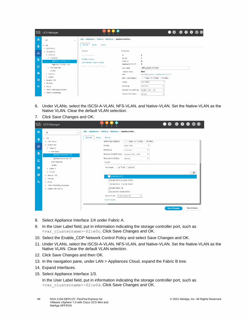
49 NVA-1154-DEPLOY: FlexPod Express for VMware vSphere 7.0 with Cisco UCS Mini and NetApp AFF/FAS
© 2021 NetApp, Inc. All Rights Reserved.
6. Under VLANs, select the iSCSI-A-VLAN, NFS-VLAN, and Native-VLAN. Set the Native-VLAN as the Native VLAN. Clear the default VLAN selection.
7. Click Save Changes and OK.
8. Select Appliance Interface 1/4 under Fabric A.
9. In the User Label field, put in information indicating the storage controller port, such as <var_clustername>-02:e0c. Click Save Changes and OK.
10. Select the Enable_CDP Network Control Policy and select Save Changes and OK.
11. Under VLANs, select the iSCSI-A-VLAN, NFS-VLAN, and Native-VLAN. Set the Native-VLAN as the Native VLAN. Clear the default VLAN selection.
12. Click Save Changes and then OK.
13. In the navigation pane, under LAN > Appliances Cloud, expand the Fabric B tree.
14. Expand Interfaces.
15. Select Appliance Interface 1/3.
In the User Label field, put in information indicating the storage controller port, such as <var_clustername>-02:e0d. Click Save Changes and OK.
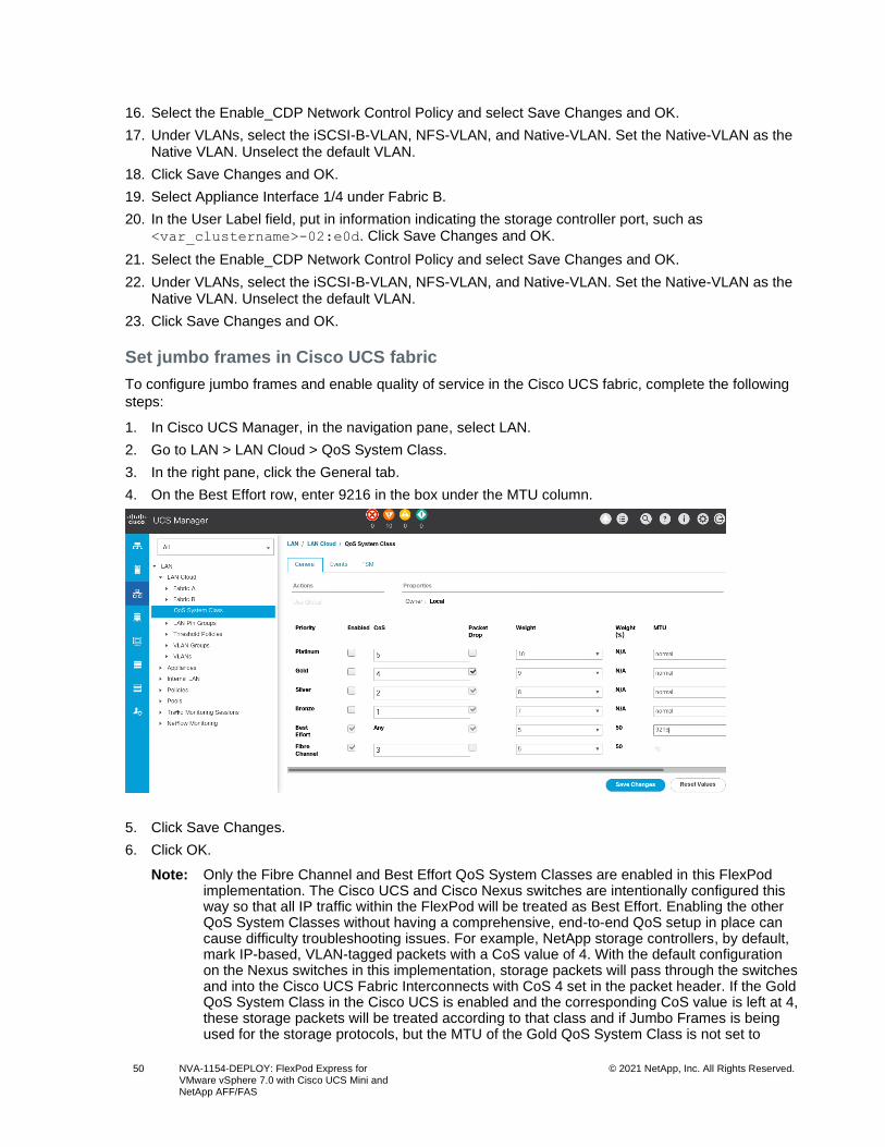
50 NVA-1154-DEPLOY: FlexPod Express for VMware vSphere 7.0 with Cisco UCS Mini and NetApp AFF/FAS
© 2021 NetApp, Inc. All Rights Reserved.
16. Select the Enable_CDP Network Control Policy and select Save Changes and OK.
17. Under VLANs, select the iSCSI-B-VLAN, NFS-VLAN, and Native-VLAN. Set the Native-VLAN as the Native VLAN. Unselect the default VLAN.
18. Click Save Changes and OK.
19. Select Appliance Interface 1/4 under Fabric B.
20. In the User Label field, put in information indicating the storage controller port, such as <var_clustername>-02:e0d. Click Save Changes and OK.
21. Select the Enable_CDP Network Control Policy and select Save Changes and OK.
22. Under VLANs, select the iSCSI-B-VLAN, NFS-VLAN, and Native-VLAN. Set the Native-VLAN as the Native VLAN. Unselect the default VLAN.
23. Click Save Changes and OK.
Set jumbo frames in Cisco UCS fabric
To configure jumbo frames and enable quality of service in the Cisco UCS fabric, complete the following
steps:
1. In Cisco UCS Manager, in the navigation pane, select LAN.
2. Go to LAN > LAN Cloud > QoS System Class.
3. In the right pane, click the General tab.
4. On the Best Effort row, enter 9216 in the box under the MTU column.
5. Click Save Changes.
6. Click OK.
Note: Only the Fibre Channel and Best Effort QoS System Classes are enabled in this FlexPod implementation. The Cisco UCS and Cisco Nexus switches are intentionally configured this way so that all IP traffic within the FlexPod will be treated as Best Effort. Enabling the other QoS System Classes without having a comprehensive, end-to-end QoS setup in place can cause difficulty troubleshooting issues. For example, NetApp storage controllers, by default, mark IP-based, VLAN-tagged packets with a CoS value of 4. With the default configuration on the Nexus switches in this implementation, storage packets will pass through the switches and into the Cisco UCS Fabric Interconnects with CoS 4 set in the packet header. If the Gold QoS System Class in the Cisco UCS is enabled and the corresponding CoS value is left at 4, these storage packets will be treated according to that class and if Jumbo Frames is being used for the storage protocols, but the MTU of the Gold QoS System Class is not set to
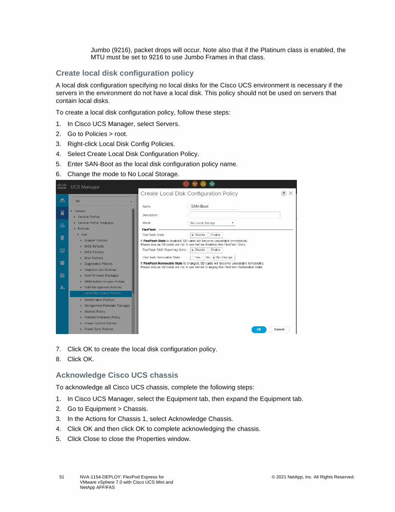
51 NVA-1154-DEPLOY: FlexPod Express for VMware vSphere 7.0 with Cisco UCS Mini and NetApp AFF/FAS
© 2021 NetApp, Inc. All Rights Reserved.
Jumbo (9216), packet drops will occur. Note also that if the Platinum class is enabled, the MTU must be set to 9216 to use Jumbo Frames in that class.
Create local disk configuration policy
A local disk configuration specifying no local disks for the Cisco UCS environment is necessary if the
servers in the environment do not have a local disk. This policy should not be used on servers that
contain local disks.
To create a local disk configuration policy, follow these steps:
1. In Cisco UCS Manager, select Servers.
2. Go to Policies > root.
3. Right-click Local Disk Config Policies.
4. Select Create Local Disk Configuration Policy.
5. Enter SAN-Boot as the local disk configuration policy name.
6. Change the mode to No Local Storage.
7. Click OK to create the local disk configuration policy.
8. Click OK.
Acknowledge Cisco UCS chassis
To acknowledge all Cisco UCS chassis, complete the following steps:
1. In Cisco UCS Manager, select the Equipment tab, then expand the Equipment tab.
2. Go to Equipment > Chassis.
3. In the Actions for Chassis 1, select Acknowledge Chassis.
4. Click OK and then click OK to complete acknowledging the chassis.
5. Click Close to close the Properties window.
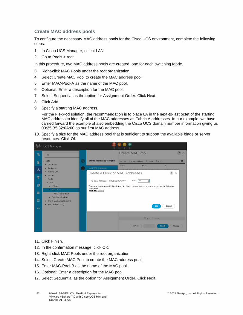
52 NVA-1154-DEPLOY: FlexPod Express for VMware vSphere 7.0 with Cisco UCS Mini and NetApp AFF/FAS
© 2021 NetApp, Inc. All Rights Reserved.
Create MAC address pools
To configure the necessary MAC address pools for the Cisco UCS environment, complete the following
steps:
1. In Cisco UCS Manager, select LAN.
2. Go to Pools > root.
In this procedure, two MAC address pools are created, one for each switching fabric.
3. Right-click MAC Pools under the root organization.
4. Select Create MAC Pool to create the MAC address pool.
5. Enter MAC-Pool-A as the name of the MAC pool.
6. Optional: Enter a description for the MAC pool.
7. Select Sequential as the option for Assignment Order. Click Next.
8. Click Add.
9. Specify a starting MAC address.
For the FlexPod solution, the recommendation is to place 0A in the next-to-last octet of the starting MAC address to identify all of the MAC addresses as Fabric A addresses. In our example, we have carried forward the example of also embedding the Cisco UCS domain number information giving us 00:25:B5:32:0A:00 as our first MAC address.
10. Specify a size for the MAC address pool that is sufficient to support the available blade or server resources. Click OK.
11. Click Finish.
12. In the confirmation message, click OK.
13. Right-click MAC Pools under the root organization.
14. Select Create MAC Pool to create the MAC address pool.
15. Enter MAC-Pool-B as the name of the MAC pool.
16. Optional: Enter a description for the MAC pool.
17. Select Sequential as the option for Assignment Order. Click Next.
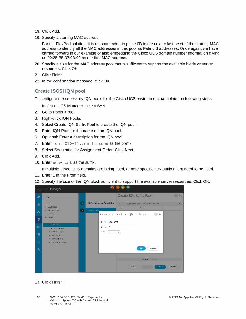
53 NVA-1154-DEPLOY: FlexPod Express for VMware vSphere 7.0 with Cisco UCS Mini and NetApp AFF/FAS
© 2021 NetApp, Inc. All Rights Reserved.
18. Click Add.
19. Specify a starting MAC address.
For the FlexPod solution, it is recommended to place 0B in the next to last octet of the starting MAC address to identify all the MAC addresses in this pool as Fabric B addresses. Once again, we have carried forward in our example of also embedding the Cisco UCS domain number information giving us 00:25:B5:32:0B:00 as our first MAC address.
20. Specify a size for the MAC address pool that is sufficient to support the available blade or server resources. Click OK.
21. Click Finish.
22. In the confirmation message, click OK.
Create iSCSI IQN pool
To configure the necessary IQN pools for the Cisco UCS environment, complete the following steps:
1. In Cisco UCS Manager, select SAN.
2. Go to Pools > root.
3. Right-click IQN Pools.
4. Select Create IQN Suffix Pool to create the IQN pool.
5. Enter IQN-Pool for the name of the IQN pool.
6. Optional: Enter a description for the IQN pool.
7. Enter iqn.2010-11.com.flexpod as the prefix.
8. Select Sequential for Assignment Order. Click Next.
9. Click Add.
10. Enter ucs-host as the suffix.
If multiple Cisco UCS domains are being used, a more specific IQN suffix might need to be used.
11. Enter 1 in the From field.
12. Specify the size of the IQN block sufficient to support the available server resources. Click OK.
13. Click Finish.
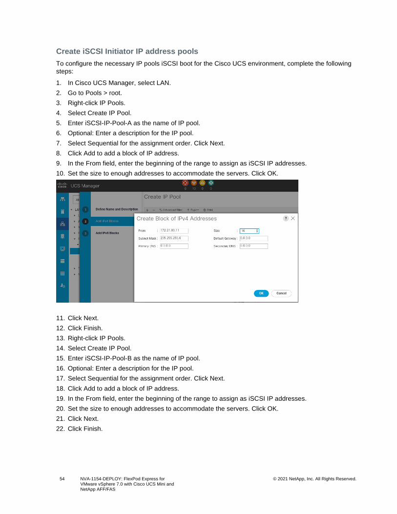
54 NVA-1154-DEPLOY: FlexPod Express for VMware vSphere 7.0 with Cisco UCS Mini and NetApp AFF/FAS
© 2021 NetApp, Inc. All Rights Reserved.
Create iSCSI Initiator IP address pools
To configure the necessary IP pools iSCSI boot for the Cisco UCS environment, complete the following
steps:
1. In Cisco UCS Manager, select LAN.
2. Go to Pools > root.
3. Right-click IP Pools.
4. Select Create IP Pool.
5. Enter iSCSI-IP-Pool-A as the name of IP pool.
6. Optional: Enter a description for the IP pool.
7. Select Sequential for the assignment order. Click Next.
8. Click Add to add a block of IP address.
9. In the From field, enter the beginning of the range to assign as iSCSI IP addresses.
10. Set the size to enough addresses to accommodate the servers. Click OK.
11. Click Next.
12. Click Finish.
13. Right-click IP Pools.
14. Select Create IP Pool.
15. Enter iSCSI-IP-Pool-B as the name of IP pool.
16. Optional: Enter a description for the IP pool.
17. Select Sequential for the assignment order. Click Next.
18. Click Add to add a block of IP address.
19. In the From field, enter the beginning of the range to assign as iSCSI IP addresses.
20. Set the size to enough addresses to accommodate the servers. Click OK.
21. Click Next.
22. Click Finish.
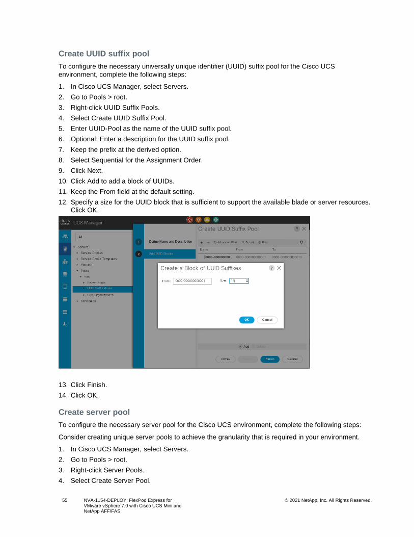
55 NVA-1154-DEPLOY: FlexPod Express for VMware vSphere 7.0 with Cisco UCS Mini and NetApp AFF/FAS
© 2021 NetApp, Inc. All Rights Reserved.
Create UUID suffix pool
To configure the necessary universally unique identifier (UUID) suffix pool for the Cisco UCS
environment, complete the following steps:
1. In Cisco UCS Manager, select Servers.
2. Go to Pools > root.
3. Right-click UUID Suffix Pools.
4. Select Create UUID Suffix Pool.
5. Enter UUID-Pool as the name of the UUID suffix pool.
6. Optional: Enter a description for the UUID suffix pool.
7. Keep the prefix at the derived option.
8. Select Sequential for the Assignment Order.
9. Click Next.
10. Click Add to add a block of UUIDs.
11. Keep the From field at the default setting.
12. Specify a size for the UUID block that is sufficient to support the available blade or server resources. Click OK.
13. Click Finish.
14. Click OK.
Create server pool
To configure the necessary server pool for the Cisco UCS environment, complete the following steps:
Consider creating unique server pools to achieve the granularity that is required in your environment.
1. In Cisco UCS Manager, select Servers.
2. Go to Pools > root.
3. Right-click Server Pools.
4. Select Create Server Pool.
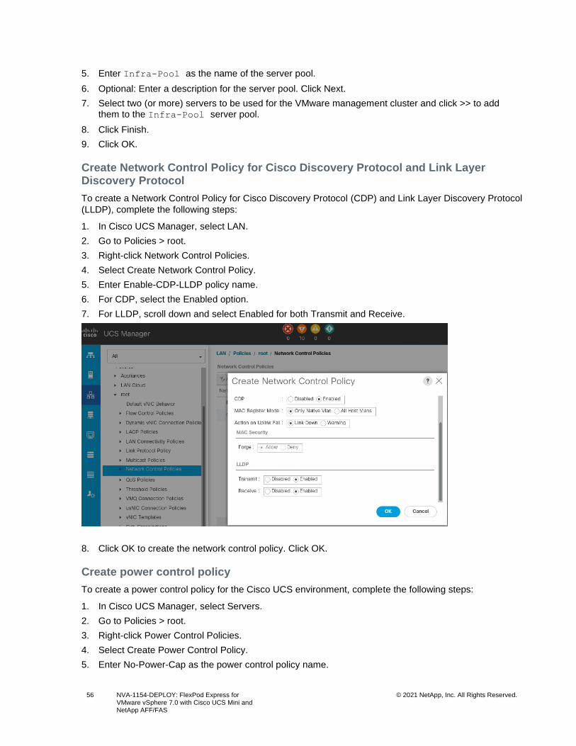
56 NVA-1154-DEPLOY: FlexPod Express for VMware vSphere 7.0 with Cisco UCS Mini and NetApp AFF/FAS
© 2021 NetApp, Inc. All Rights Reserved.
5. Enter Infra-Pool as the name of the server pool.
6. Optional: Enter a description for the server pool. Click Next.
7. Select two (or more) servers to be used for the VMware management cluster and click >> to add them to the Infra-Pool server pool.
8. Click Finish.
9. Click OK.
Create Network Control Policy for Cisco Discovery Protocol and Link Layer Discovery Protocol
To create a Network Control Policy for Cisco Discovery Protocol (CDP) and Link Layer Discovery Protocol
(LLDP), complete the following steps:
1. In Cisco UCS Manager, select LAN.
2. Go to Policies > root.
3. Right-click Network Control Policies.
4. Select Create Network Control Policy.
5. Enter Enable-CDP-LLDP policy name.
6. For CDP, select the Enabled option.
7. For LLDP, scroll down and select Enabled for both Transmit and Receive.
8. Click OK to create the network control policy. Click OK.
Create power control policy
To create a power control policy for the Cisco UCS environment, complete the following steps:
1. In Cisco UCS Manager, select Servers.
2. Go to Policies > root.
3. Right-click Power Control Policies.
4. Select Create Power Control Policy.
5. Enter No-Power-Cap as the power control policy name.
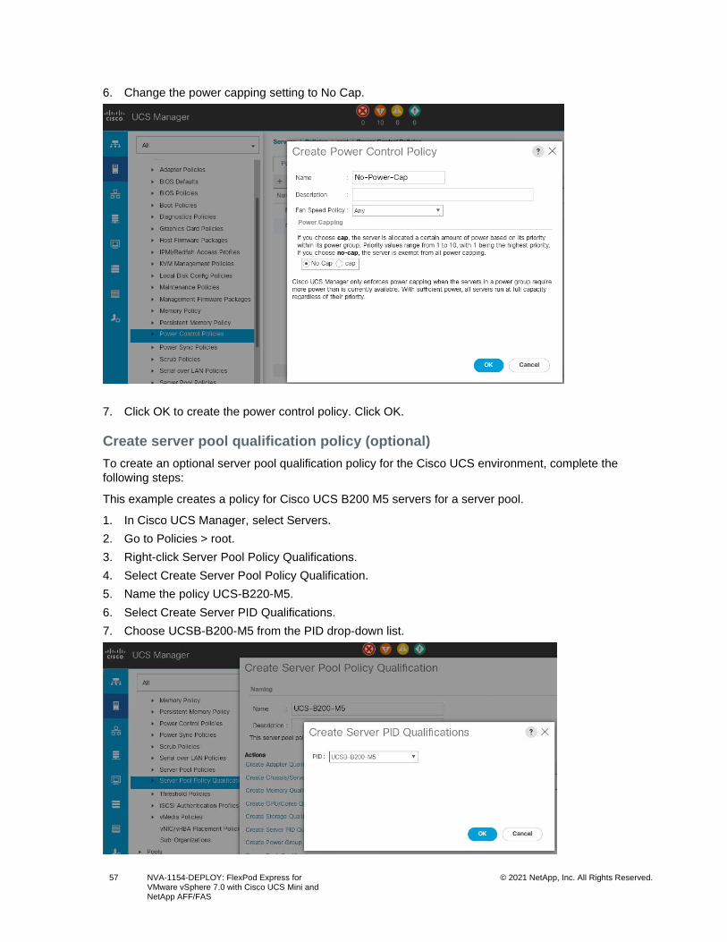
57 NVA-1154-DEPLOY: FlexPod Express for VMware vSphere 7.0 with Cisco UCS Mini and NetApp AFF/FAS
© 2021 NetApp, Inc. All Rights Reserved.
6. Change the power capping setting to No Cap.
7. Click OK to create the power control policy. Click OK.
Create server pool qualification policy (optional)
To create an optional server pool qualification policy for the Cisco UCS environment, complete the
following steps:
This example creates a policy for Cisco UCS B200 M5 servers for a server pool.
1. In Cisco UCS Manager, select Servers.
2. Go to Policies > root.
3. Right-click Server Pool Policy Qualifications.
4. Select Create Server Pool Policy Qualification.
5. Name the policy UCS-B220-M5.
6. Select Create Server PID Qualifications.
7. Choose UCSB-B200-M5 from the PID drop-down list.
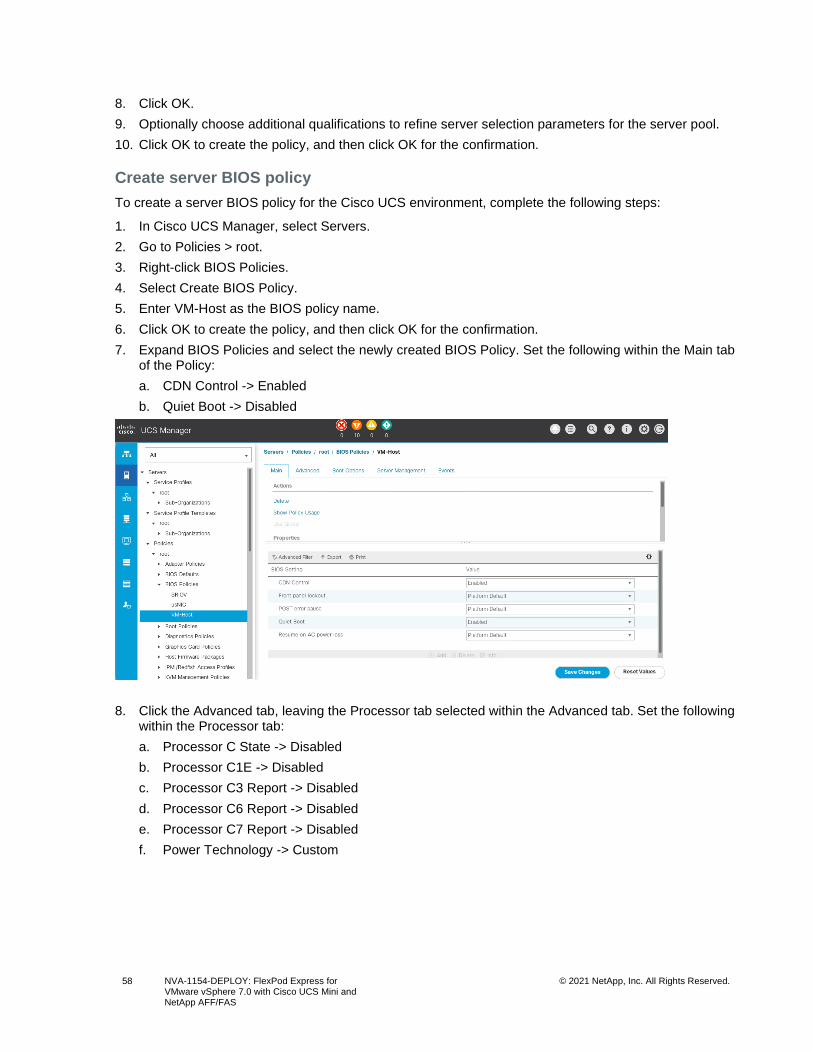
58 NVA-1154-DEPLOY: FlexPod Express for VMware vSphere 7.0 with Cisco UCS Mini and NetApp AFF/FAS
© 2021 NetApp, Inc. All Rights Reserved.
8. Click OK.
9. Optionally choose additional qualifications to refine server selection parameters for the server pool.
10. Click OK to create the policy, and then click OK for the confirmation.
Create server BIOS policy
To create a server BIOS policy for the Cisco UCS environment, complete the following steps:
1. In Cisco UCS Manager, select Servers.
2. Go to Policies > root.
3. Right-click BIOS Policies.
4. Select Create BIOS Policy.
5. Enter VM-Host as the BIOS policy name.
6. Click OK to create the policy, and then click OK for the confirmation.
7. Expand BIOS Policies and select the newly created BIOS Policy. Set the following within the Main tab of the Policy:
a. CDN Control -> Enabled
b. Quiet Boot -> Disabled
8. Click the Advanced tab, leaving the Processor tab selected within the Advanced tab. Set the following within the Processor tab:
a. Processor C State -> Disabled
b. Processor C1E -> Disabled
c. Processor C3 Report -> Disabled
d. Processor C6 Report -> Disabled
e. Processor C7 Report -> Disabled
f. Power Technology -> Custom
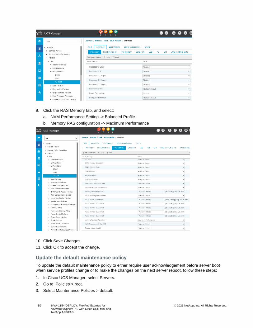
59 NVA-1154-DEPLOY: FlexPod Express for VMware vSphere 7.0 with Cisco UCS Mini and NetApp AFF/FAS
© 2021 NetApp, Inc. All Rights Reserved.
9. Click the RAS Memory tab, and select:
a. NVM Performance Setting -> Balanced Profile
b. Memory RAS configuration -> Maximum Performance
10. Click Save Changes.
11. Click OK to accept the change.
Update the default maintenance policy
To update the default maintenance policy to either require user acknowledgement before server boot
when service profiles change or to make the changes on the next server reboot, follow these steps:
1. In Cisco UCS Manager, select Servers.
2. Go to Policies > root.
3. Select Maintenance Policies > default.
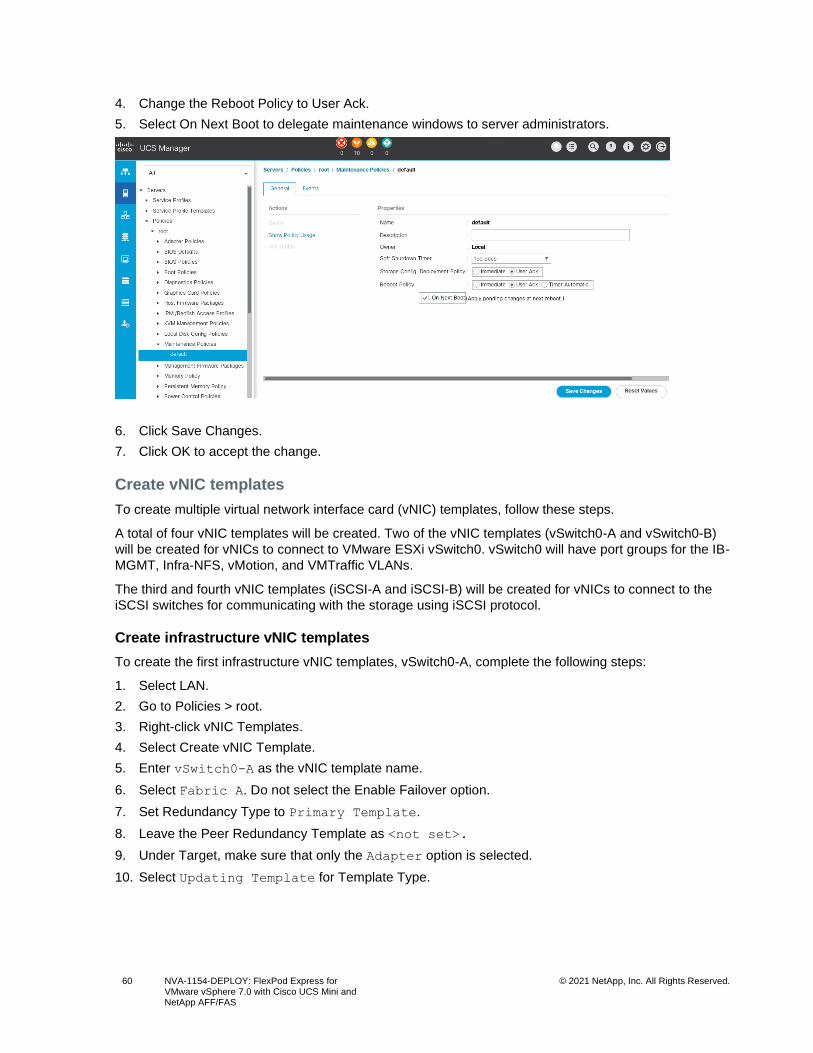
60 NVA-1154-DEPLOY: FlexPod Express for VMware vSphere 7.0 with Cisco UCS Mini and NetApp AFF/FAS
© 2021 NetApp, Inc. All Rights Reserved.
4. Change the Reboot Policy to User Ack.
5. Select On Next Boot to delegate maintenance windows to server administrators.
6. Click Save Changes.
7. Click OK to accept the change.
Create vNIC templates
To create multiple virtual network interface card (vNIC) templates, follow these steps.
A total of four vNIC templates will be created. Two of the vNIC templates (vSwitch0-A and vSwitch0-B)
will be created for vNICs to connect to VMware ESXi vSwitch0. vSwitch0 will have port groups for the IB-
MGMT, Infra-NFS, vMotion, and VMTraffic VLANs.
The third and fourth vNIC templates (iSCSI-A and iSCSI-B) will be created for vNICs to connect to the
iSCSI switches for communicating with the storage using iSCSI protocol.
Create infrastructure vNIC templates
To create the first infrastructure vNIC templates, vSwitch0-A, complete the following steps:
1. Select LAN.
2. Go to Policies > root.
3. Right-click vNIC Templates.
4. Select Create vNIC Template.
5. Enter vSwitch0-A as the vNIC template name.
6. Select Fabric A. Do not select the Enable Failover option.
7. Set Redundancy Type to Primary Template.
8. Leave the Peer Redundancy Template as <not set>.
9. Under Target, make sure that only the Adapter option is selected.
10. Select Updating Template for Template Type.
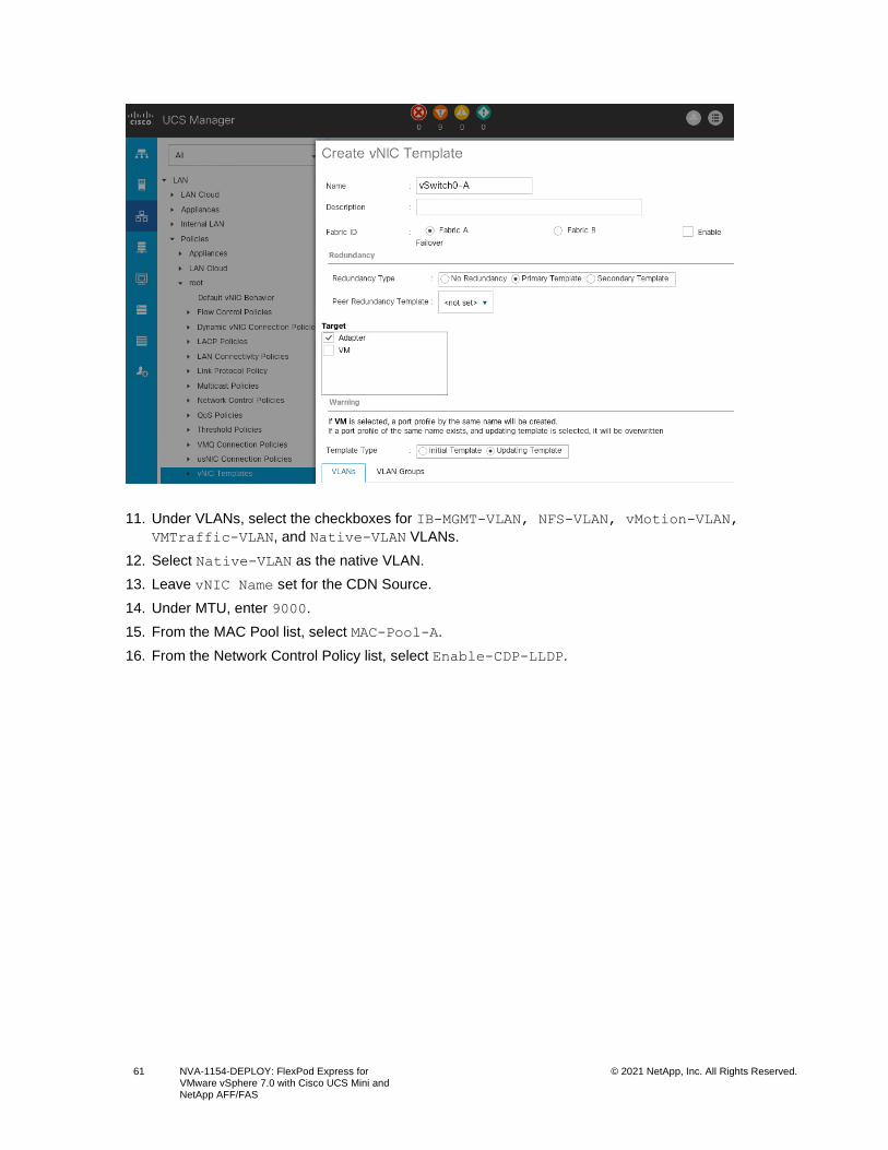
61 NVA-1154-DEPLOY: FlexPod Express for VMware vSphere 7.0 with Cisco UCS Mini and NetApp AFF/FAS
© 2021 NetApp, Inc. All Rights Reserved.
11. Under VLANs, select the checkboxes for IB-MGMT-VLAN, NFS-VLAN, vMotion-VLAN,
VMTraffic-VLAN, and Native-VLAN VLANs.
12. Select Native-VLAN as the native VLAN.
13. Leave vNIC Name set for the CDN Source.
14. Under MTU, enter 9000.
15. From the MAC Pool list, select MAC-Pool-A.
16. From the Network Control Policy list, select Enable-CDP-LLDP.
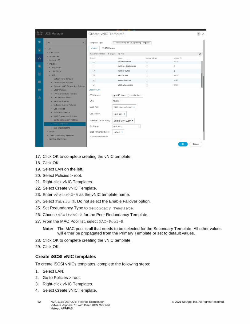
62 NVA-1154-DEPLOY: FlexPod Express for VMware vSphere 7.0 with Cisco UCS Mini and NetApp AFF/FAS
© 2021 NetApp, Inc. All Rights Reserved.
17. Click OK to complete creating the vNIC template.
18. Click OK.
19. Select LAN on the left.
20. Select Policies > root.
21. Right-click vNIC Templates.
22. Select Create vNIC Template.
23. Enter vSwitch0-B as the vNIC template name.
24. Select Fabric B. Do not select the Enable Failover option.
25. Set Redundancy Type to Secondary Template.
26. Choose vSwitch0-A for the Peer Redundancy Template.
27. From the MAC Pool list, select MAC-Pool-B.
Note: The MAC pool is all that needs to be selected for the Secondary Template. All other values will either be propagated from the Primary Template or set to default values.
28. Click OK to complete creating the vNIC template.
29. Click OK.
Create iSCSI vNIC templates
To create iSCSI vNICs templates, complete the following steps:
1. Select LAN.
2. Go to Policies > root.
3. Right-click vNIC Templates.
4. Select Create vNIC Template.
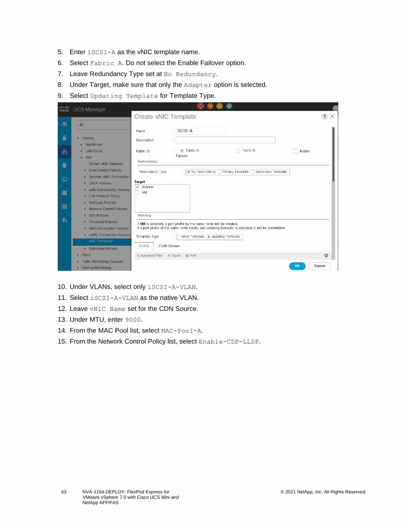
63 NVA-1154-DEPLOY: FlexPod Express for VMware vSphere 7.0 with Cisco UCS Mini and NetApp AFF/FAS
© 2021 NetApp, Inc. All Rights Reserved.
5. Enter iSCSI-A as the vNIC template name.
6. Select Fabric A. Do not select the Enable Failover option.
7. Leave Redundancy Type set at No Redundancy.
8. Under Target, make sure that only the Adapter option is selected.
9. Select Updating Template for Template Type.
10. Under VLANs, select only iSCSI-A-VLAN.
11. Select iSCSI-A-VLAN as the native VLAN.
12. Leave vNIC Name set for the CDN Source.
13. Under MTU, enter 9000.
14. From the MAC Pool list, select MAC-Pool-A.
15. From the Network Control Policy list, select Enable-CDP-LLDP.
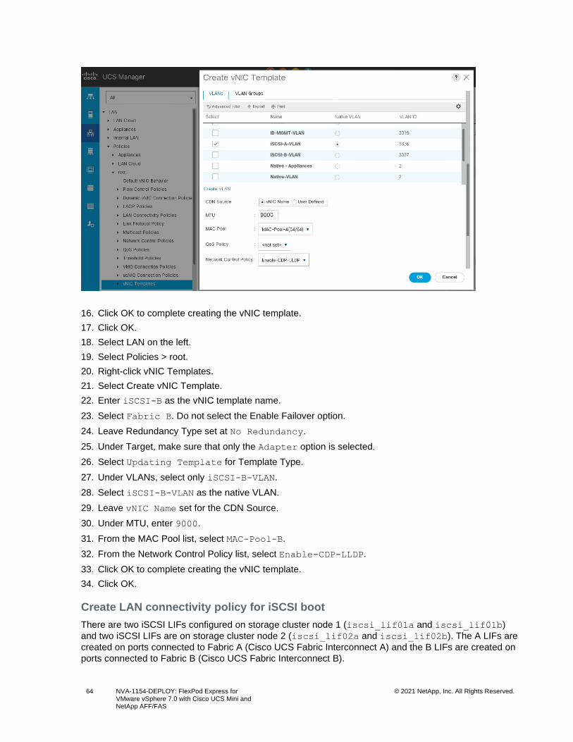
64 NVA-1154-DEPLOY: FlexPod Express for VMware vSphere 7.0 with Cisco UCS Mini and NetApp AFF/FAS
© 2021 NetApp, Inc. All Rights Reserved.
16. Click OK to complete creating the vNIC template.
17. Click OK.
18. Select LAN on the left.
19. Select Policies > root.
20. Right-click vNIC Templates.
21. Select Create vNIC Template.
22. Enter iSCSI-B as the vNIC template name.
23. Select Fabric B. Do not select the Enable Failover option.
24. Leave Redundancy Type set at No Redundancy.
25. Under Target, make sure that only the Adapter option is selected.
26. Select Updating Template for Template Type.
27. Under VLANs, select only iSCSI-B-VLAN.
28. Select iSCSI-B-VLAN as the native VLAN.
29. Leave vNIC Name set for the CDN Source.
30. Under MTU, enter 9000.
31. From the MAC Pool list, select MAC-Pool-B.
32. From the Network Control Policy list, select Enable-CDP-LLDP.
33. Click OK to complete creating the vNIC template.
34. Click OK.
Create LAN connectivity policy for iSCSI boot
There are two iSCSI LIFs configured on storage cluster node 1 (iscsi_lif01a and iscsi_lif01b)
and two iSCSI LIFs are on storage cluster node 2 (iscsi_lif02a and iscsi_lif02b). The A LIFs are
created on ports connected to Fabric A (Cisco UCS Fabric Interconnect A) and the B LIFs are created on
ports connected to Fabric B (Cisco UCS Fabric Interconnect B).
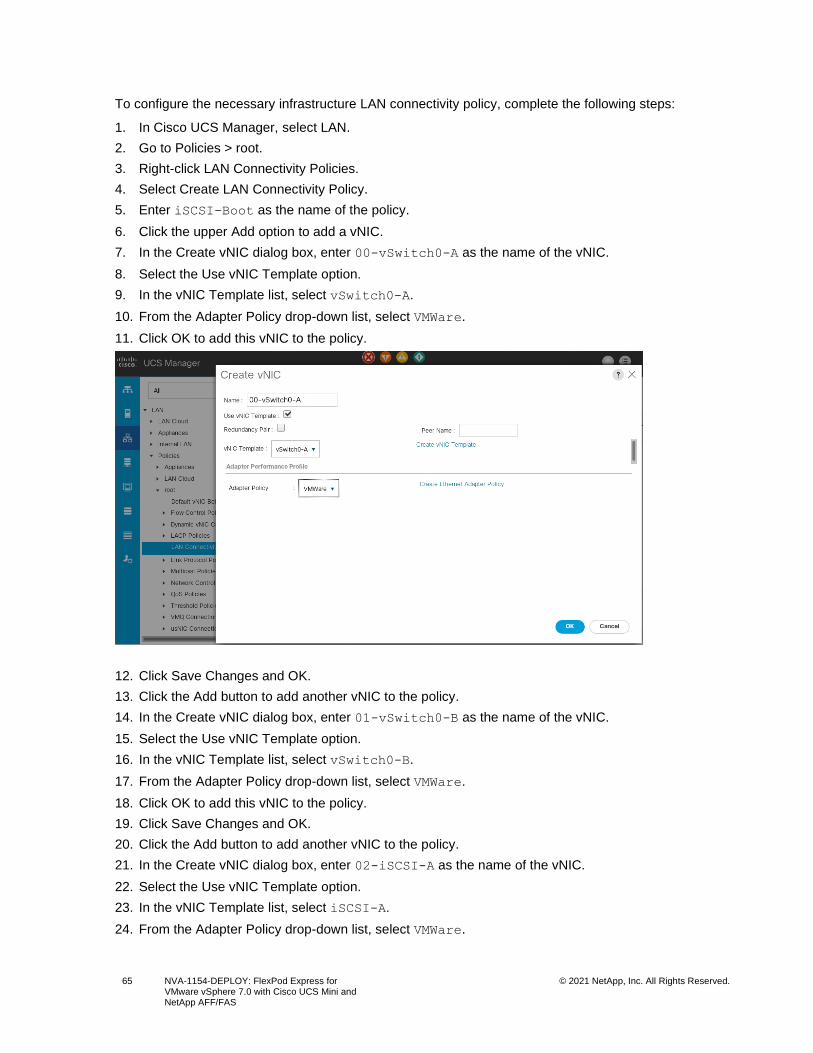
65 NVA-1154-DEPLOY: FlexPod Express for VMware vSphere 7.0 with Cisco UCS Mini and NetApp AFF/FAS
© 2021 NetApp, Inc. All Rights Reserved.
To configure the necessary infrastructure LAN connectivity policy, complete the following steps:
1. In Cisco UCS Manager, select LAN.
2. Go to Policies > root.
3. Right-click LAN Connectivity Policies.
4. Select Create LAN Connectivity Policy.
5. Enter iSCSI-Boot as the name of the policy.
6. Click the upper Add option to add a vNIC.
7. In the Create vNIC dialog box, enter 00-vSwitch0-A as the name of the vNIC.
8. Select the Use vNIC Template option.
9. In the vNIC Template list, select vSwitch0-A.
10. From the Adapter Policy drop-down list, select VMWare.
11. Click OK to add this vNIC to the policy.
12. Click Save Changes and OK.
13. Click the Add button to add another vNIC to the policy.
14. In the Create vNIC dialog box, enter 01-vSwitch0-B as the name of the vNIC.
15. Select the Use vNIC Template option.
16. In the vNIC Template list, select vSwitch0-B.
17. From the Adapter Policy drop-down list, select VMWare.
18. Click OK to add this vNIC to the policy.
19. Click Save Changes and OK.
20. Click the Add button to add another vNIC to the policy.
21. In the Create vNIC dialog box, enter 02-iSCSI-A as the name of the vNIC.
22. Select the Use vNIC Template option.
23. In the vNIC Template list, select iSCSI-A.
24. From the Adapter Policy drop-down list, select VMWare.
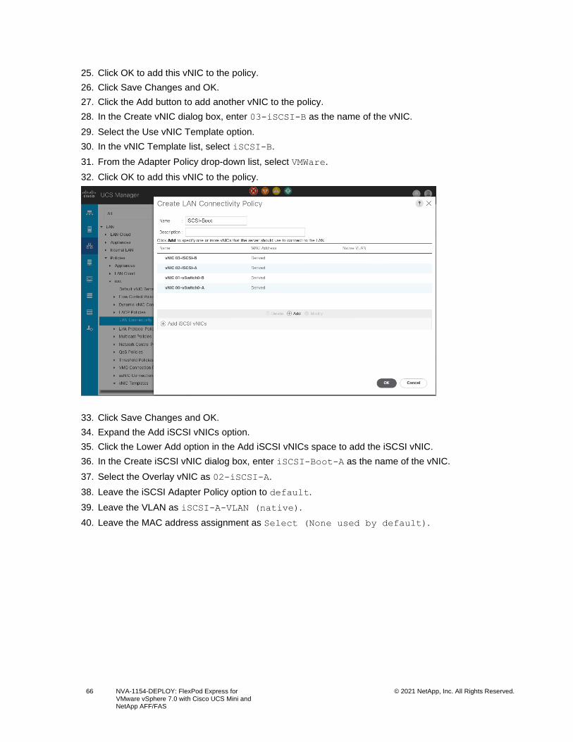
66 NVA-1154-DEPLOY: FlexPod Express for VMware vSphere 7.0 with Cisco UCS Mini and NetApp AFF/FAS
© 2021 NetApp, Inc. All Rights Reserved.
25. Click OK to add this vNIC to the policy.
26. Click Save Changes and OK.
27. Click the Add button to add another vNIC to the policy.
28. In the Create vNIC dialog box, enter 03-iSCSI-B as the name of the vNIC.
29. Select the Use vNIC Template option.
30. In the vNIC Template list, select iSCSI-B.
31. From the Adapter Policy drop-down list, select VMWare.
32. Click OK to add this vNIC to the policy.
33. Click Save Changes and OK.
34. Expand the Add iSCSI vNICs option.
35. Click the Lower Add option in the Add iSCSI vNICs space to add the iSCSI vNIC.
36. In the Create iSCSI vNIC dialog box, enter iSCSI-Boot-A as the name of the vNIC.
37. Select the Overlay vNIC as 02-iSCSI-A.
38. Leave the iSCSI Adapter Policy option to default.
39. Leave the VLAN as iSCSI-A-VLAN (native).
40. Leave the MAC address assignment as Select (None used by default).
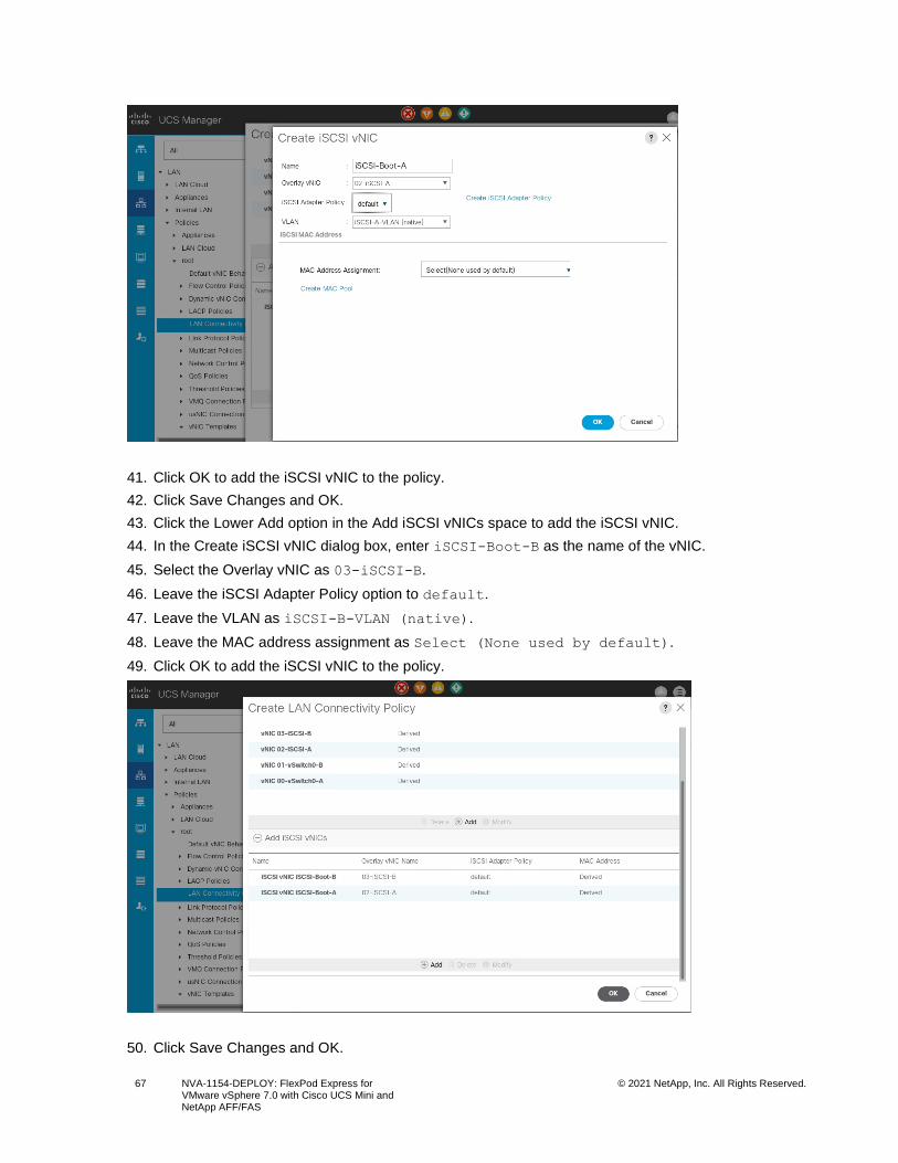
67 NVA-1154-DEPLOY: FlexPod Express for VMware vSphere 7.0 with Cisco UCS Mini and NetApp AFF/FAS
© 2021 NetApp, Inc. All Rights Reserved.
41. Click OK to add the iSCSI vNIC to the policy.
42. Click Save Changes and OK.
43. Click the Lower Add option in the Add iSCSI vNICs space to add the iSCSI vNIC.
44. In the Create iSCSI vNIC dialog box, enter iSCSI-Boot-B as the name of the vNIC.
45. Select the Overlay vNIC as 03-iSCSI-B.
46. Leave the iSCSI Adapter Policy option to default.
47. Leave the VLAN as iSCSI-B-VLAN (native).
48. Leave the MAC address assignment as Select (None used by default).
49. Click OK to add the iSCSI vNIC to the policy.
50. Click Save Changes and OK.
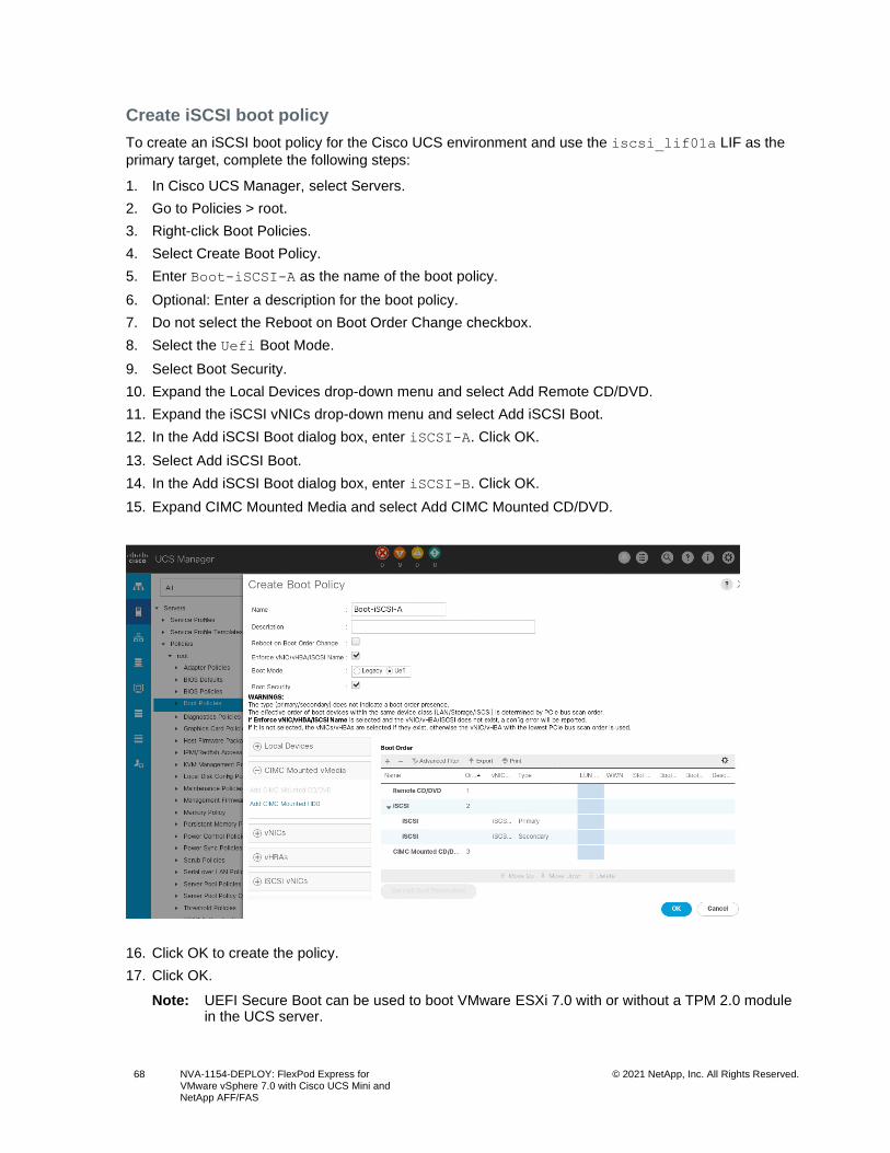
68 NVA-1154-DEPLOY: FlexPod Express for VMware vSphere 7.0 with Cisco UCS Mini and NetApp AFF/FAS
© 2021 NetApp, Inc. All Rights Reserved.
Create iSCSI boot policy
To create an iSCSI boot policy for the Cisco UCS environment and use the iscsi_lif01a LIF as the
primary target, complete the following steps:
1. In Cisco UCS Manager, select Servers.
2. Go to Policies > root.
3. Right-click Boot Policies.
4. Select Create Boot Policy.
5. Enter Boot-iSCSI-A as the name of the boot policy.
6. Optional: Enter a description for the boot policy.
7. Do not select the Reboot on Boot Order Change checkbox.
8. Select the Uefi Boot Mode.
9. Select Boot Security.
10. Expand the Local Devices drop-down menu and select Add Remote CD/DVD.
11. Expand the iSCSI vNICs drop-down menu and select Add iSCSI Boot.
12. In the Add iSCSI Boot dialog box, enter iSCSI-A. Click OK.
13. Select Add iSCSI Boot.
14. In the Add iSCSI Boot dialog box, enter iSCSI-B. Click OK.
15. Expand CIMC Mounted Media and select Add CIMC Mounted CD/DVD.
16. Click OK to create the policy.
17. Click OK.
Note: UEFI Secure Boot can be used to boot VMware ESXi 7.0 with or without a TPM 2.0 module in the UCS server.
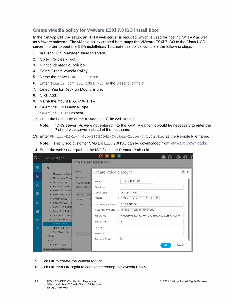
69 NVA-1154-DEPLOY: FlexPod Express for VMware vSphere 7.0 with Cisco UCS Mini and NetApp AFF/FAS
© 2021 NetApp, Inc. All Rights Reserved.
Create vMedia policy for VMware ESXi 7.0 ISO install boot
In the NetApp ONTAP setup, an HTTP web server is required, which is used for hosting ONTAP as well
as VMware software. The vMedia policy created here maps the VMware ESXi 7 ISO to the Cisco UCS
server in order to boot the ESXi installation. To create this policy, complete the following steps:
1. In Cisco UCS Manager, select Servers.
2. Go to Policies > root.
3. Right click vMedia Policies.
4. Select Create vMedia Policy.
5. Name the policy ESXi-7.0-HTTP.
6. Enter “Mounts ISO for ESXi 7.0” in the Description field.
7. Select Yes for Retry on Mount failure.
8. Click Add.
9. Name the mount ESXi-7.0-HTTP.
10. Select the CDD Device Type.
11. Select the HTTP Protocol.
12. Enter the hostname or the IP Address of the web server.
Note: If DNS server IPs were not entered into the KVM IP earlier, it would be necessary to enter the IP of the web server instead of the hostname.
13. Enter VMware-ESXi-7.0.0-16324942-Custom-Cisco-4.1.2a.iso as the Remote File name.
Note: This Cisco customer VMware ESXi 7.0 ISO can be downloaded from VMware Downloads.
14. Enter the web server path to the ISO file in the Remote Path field.
15. Click OK to create the vMedia Mount.
16. Click OK then OK again to complete creating the vMedia Policy.
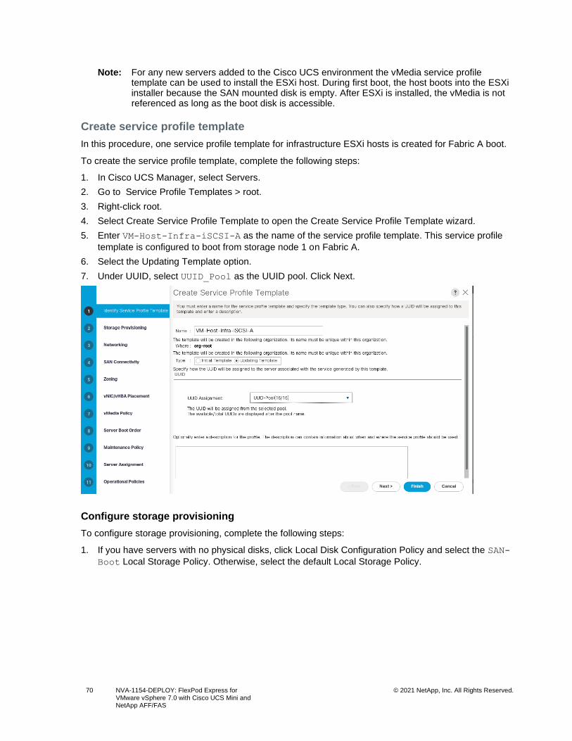
70 NVA-1154-DEPLOY: FlexPod Express for VMware vSphere 7.0 with Cisco UCS Mini and NetApp AFF/FAS
© 2021 NetApp, Inc. All Rights Reserved.
Note: For any new servers added to the Cisco UCS environment the vMedia service profile template can be used to install the ESXi host. During first boot, the host boots into the ESXi installer because the SAN mounted disk is empty. After ESXi is installed, the vMedia is not referenced as long as the boot disk is accessible.
Create service profile template
In this procedure, one service profile template for infrastructure ESXi hosts is created for Fabric A boot.
To create the service profile template, complete the following steps:
1. In Cisco UCS Manager, select Servers.
2. Go to Service Profile Templates > root.
3. Right-click root.
4. Select Create Service Profile Template to open the Create Service Profile Template wizard.
5. Enter VM-Host-Infra-iSCSI-A as the name of the service profile template. This service profile
template is configured to boot from storage node 1 on Fabric A.
6. Select the Updating Template option.
7. Under UUID, select UUID_Pool as the UUID pool. Click Next.
Configure storage provisioning
To configure storage provisioning, complete the following steps:
1. If you have servers with no physical disks, click Local Disk Configuration Policy and select the SAN-
Boot Local Storage Policy. Otherwise, select the default Local Storage Policy.
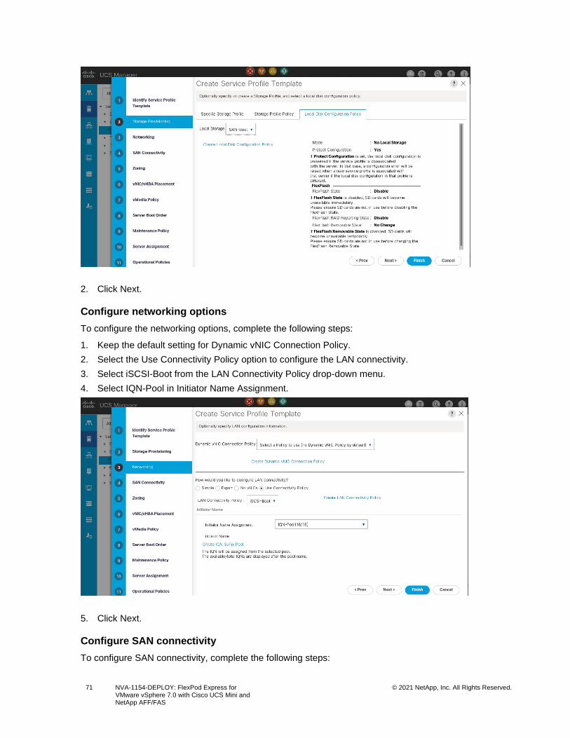
71 NVA-1154-DEPLOY: FlexPod Express for VMware vSphere 7.0 with Cisco UCS Mini and NetApp AFF/FAS
© 2021 NetApp, Inc. All Rights Reserved.
2. Click Next.
Configure networking options
To configure the networking options, complete the following steps:
1. Keep the default setting for Dynamic vNIC Connection Policy.
2. Select the Use Connectivity Policy option to configure the LAN connectivity.
3. Select iSCSI-Boot from the LAN Connectivity Policy drop-down menu.
4. Select IQN-Pool in Initiator Name Assignment.
5. Click Next.
Configure SAN connectivity
To configure SAN connectivity, complete the following steps:
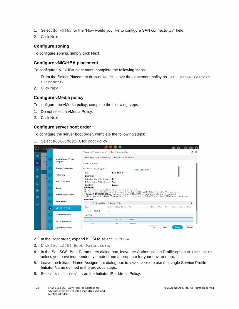
72 NVA-1154-DEPLOY: FlexPod Express for VMware vSphere 7.0 with Cisco UCS Mini and NetApp AFF/FAS
© 2021 NetApp, Inc. All Rights Reserved.
1. Select No vHBAs for the “How would you like to configure SAN connectivity?” field.
2. Click Next.
Configure zoning
To configure zoning, simply click Next.
Configure vNIC/HBA placement
To configure vNIC/HBA placement, complete the following steps:
1. From the Select Placement drop-down list, leave the placement policy as Let System Perform
Placement.
2. Click Next.
Configure vMedia policy
To configure the vMedia policy, complete the following steps:
1. Do not select a vMedia Policy.
2. Click Next.
Configure server boot order
To configure the server boot order, complete the following steps:
1. Select Boot-iSCSI-A for Boot Policy.
2. In the Boot order, expand iSCSI to select iSCSI-A.
3. Click Set iSCSI Boot Parameters.
4. In the Set iSCSI Boot Parameters dialog box, leave the Authentication Profile option to <not set>
unless you have independently created one appropriate for your environment.
5. Leave the Initiator Name Assignment dialog box to <not set> to use the single Service Profile
Initiator Name defined in the previous steps.
6. Set iSCSI_IP_Pool_A as the Initiator IP address Policy.
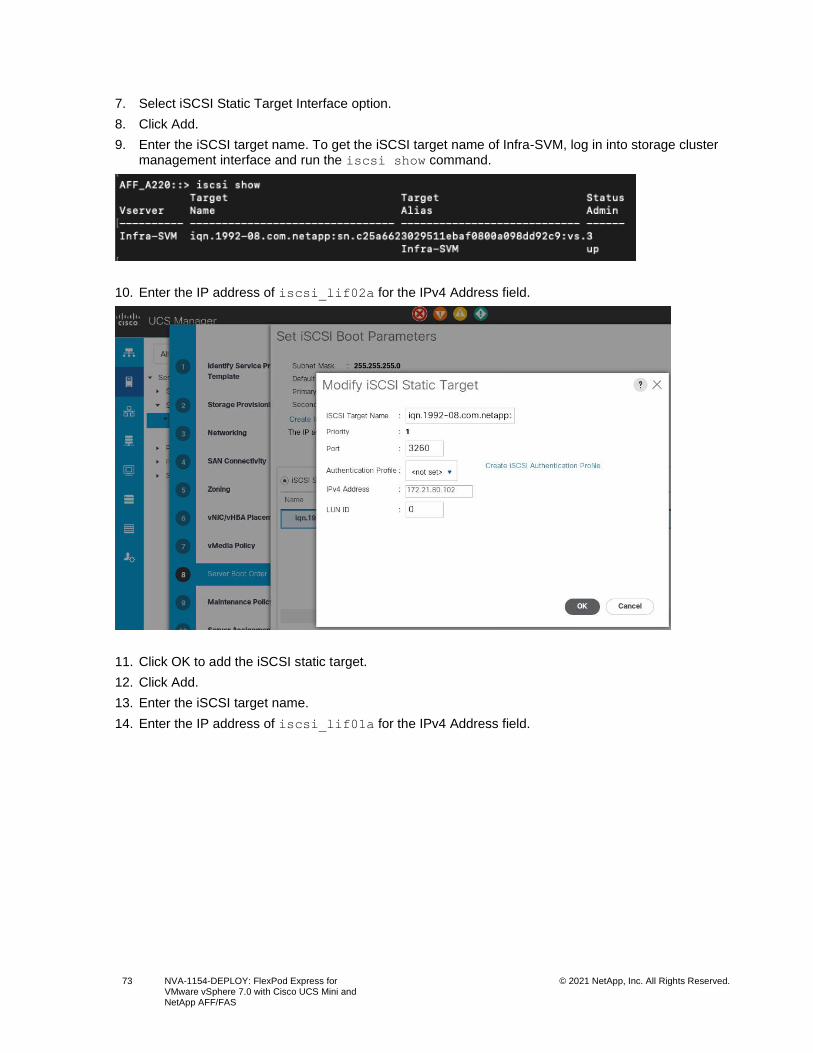
73 NVA-1154-DEPLOY: FlexPod Express for VMware vSphere 7.0 with Cisco UCS Mini and NetApp AFF/FAS
© 2021 NetApp, Inc. All Rights Reserved.
7. Select iSCSI Static Target Interface option.
8. Click Add.
9. Enter the iSCSI target name. To get the iSCSI target name of Infra-SVM, log in into storage cluster management interface and run the iscsi show command.
10. Enter the IP address of iscsi_lif02a for the IPv4 Address field.
11. Click OK to add the iSCSI static target.
12. Click Add.
13. Enter the iSCSI target name.
14. Enter the IP address of iscsi_lif01a for the IPv4 Address field.
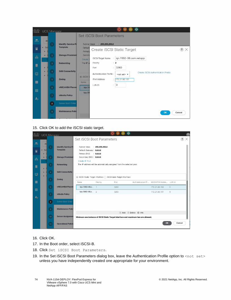
74 NVA-1154-DEPLOY: FlexPod Express for VMware vSphere 7.0 with Cisco UCS Mini and NetApp AFF/FAS
© 2021 NetApp, Inc. All Rights Reserved.
15. Click OK to add the iSCSI static target.
16. Click OK.
17. In the Boot order, select iSCSI-B.
18. Click Set iSCSI Boot Parameters.
19. In the Set iSCSI Boot Parameters dialog box, leave the Authentication Profile option to <not set>
unless you have independently created one appropriate for your environment.
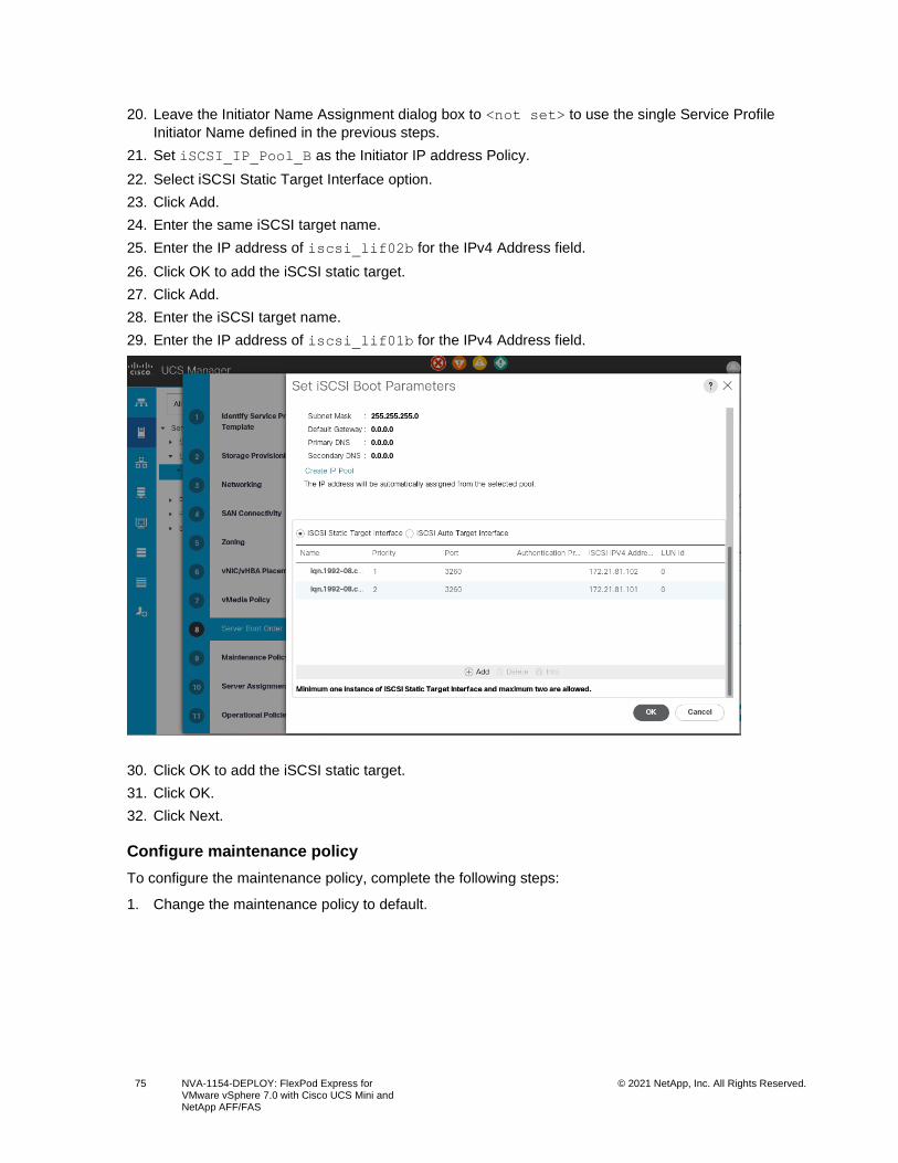
75 NVA-1154-DEPLOY: FlexPod Express for VMware vSphere 7.0 with Cisco UCS Mini and NetApp AFF/FAS
© 2021 NetApp, Inc. All Rights Reserved.
20. Leave the Initiator Name Assignment dialog box to <not set> to use the single Service Profile
Initiator Name defined in the previous steps.
21. Set iSCSI_IP_Pool_B as the Initiator IP address Policy.
22. Select iSCSI Static Target Interface option.
23. Click Add.
24. Enter the same iSCSI target name.
25. Enter the IP address of iscsi_lif02b for the IPv4 Address field.
26. Click OK to add the iSCSI static target.
27. Click Add.
28. Enter the iSCSI target name.
29. Enter the IP address of iscsi_lif01b for the IPv4 Address field.
30. Click OK to add the iSCSI static target.
31. Click OK.
32. Click Next.
Configure maintenance policy
To configure the maintenance policy, complete the following steps:
1. Change the maintenance policy to default.
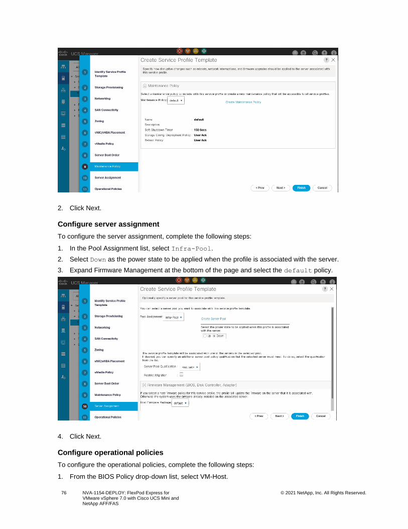
76 NVA-1154-DEPLOY: FlexPod Express for VMware vSphere 7.0 with Cisco UCS Mini and NetApp AFF/FAS
© 2021 NetApp, Inc. All Rights Reserved.
2. Click Next.
Configure server assignment
To configure the server assignment, complete the following steps:
1. In the Pool Assignment list, select Infra-Pool.
2. Select Down as the power state to be applied when the profile is associated with the server.
3. Expand Firmware Management at the bottom of the page and select the default policy.
4. Click Next.
Configure operational policies
To configure the operational policies, complete the following steps:
1. From the BIOS Policy drop-down list, select VM-Host.
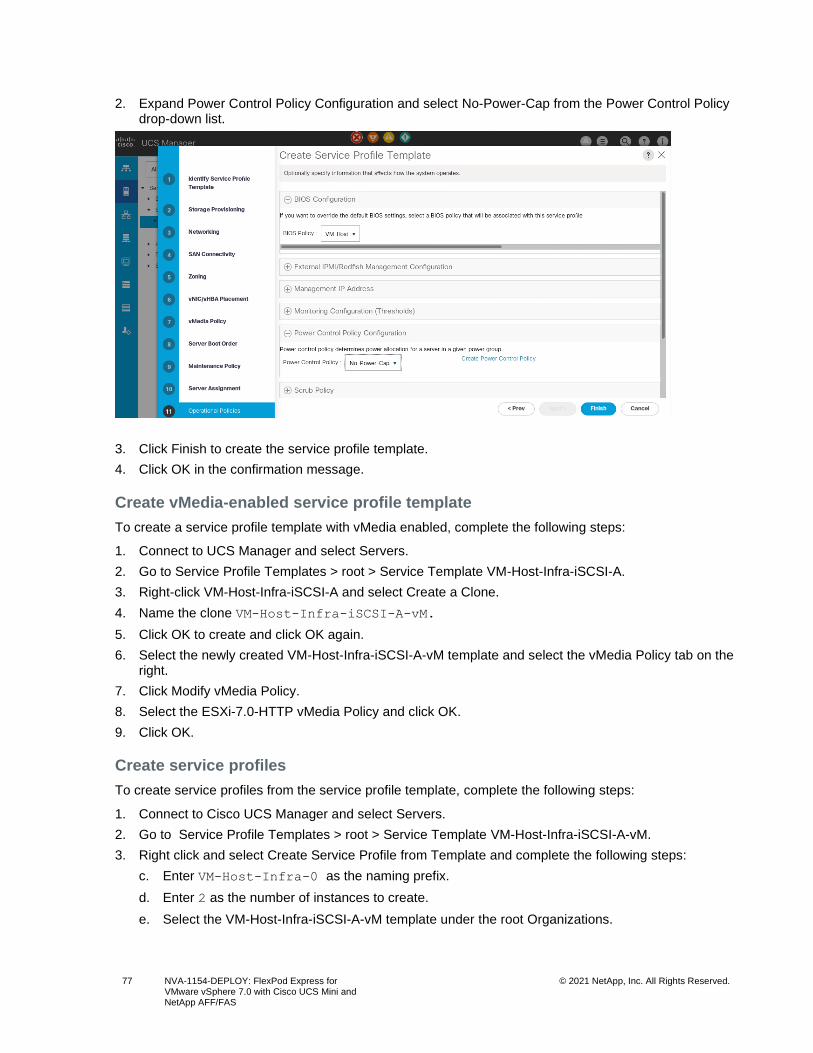
77 NVA-1154-DEPLOY: FlexPod Express for VMware vSphere 7.0 with Cisco UCS Mini and NetApp AFF/FAS
© 2021 NetApp, Inc. All Rights Reserved.
2. Expand Power Control Policy Configuration and select No-Power-Cap from the Power Control Policy drop-down list.
3. Click Finish to create the service profile template.
4. Click OK in the confirmation message.
Create vMedia-enabled service profile template
To create a service profile template with vMedia enabled, complete the following steps:
1. Connect to UCS Manager and select Servers.
2. Go to Service Profile Templates > root > Service Template VM-Host-Infra-iSCSI-A.
3. Right-click VM-Host-Infra-iSCSI-A and select Create a Clone.
4. Name the clone VM-Host-Infra-iSCSI-A-vM.
5. Click OK to create and click OK again.
6. Select the newly created VM-Host-Infra-iSCSI-A-vM template and select the vMedia Policy tab on the right.
7. Click Modify vMedia Policy.
8. Select the ESXi-7.0-HTTP vMedia Policy and click OK.
9. Click OK.
Create service profiles
To create service profiles from the service profile template, complete the following steps:
1. Connect to Cisco UCS Manager and select Servers.
2. Go to Service Profile Templates > root > Service Template VM-Host-Infra-iSCSI-A-vM.
3. Right click and select Create Service Profile from Template and complete the following steps:
c. Enter VM-Host-Infra-0 as the naming prefix.
d. Enter 2 as the number of instances to create.
e. Select the VM-Host-Infra-iSCSI-A-vM template under the root Organizations.
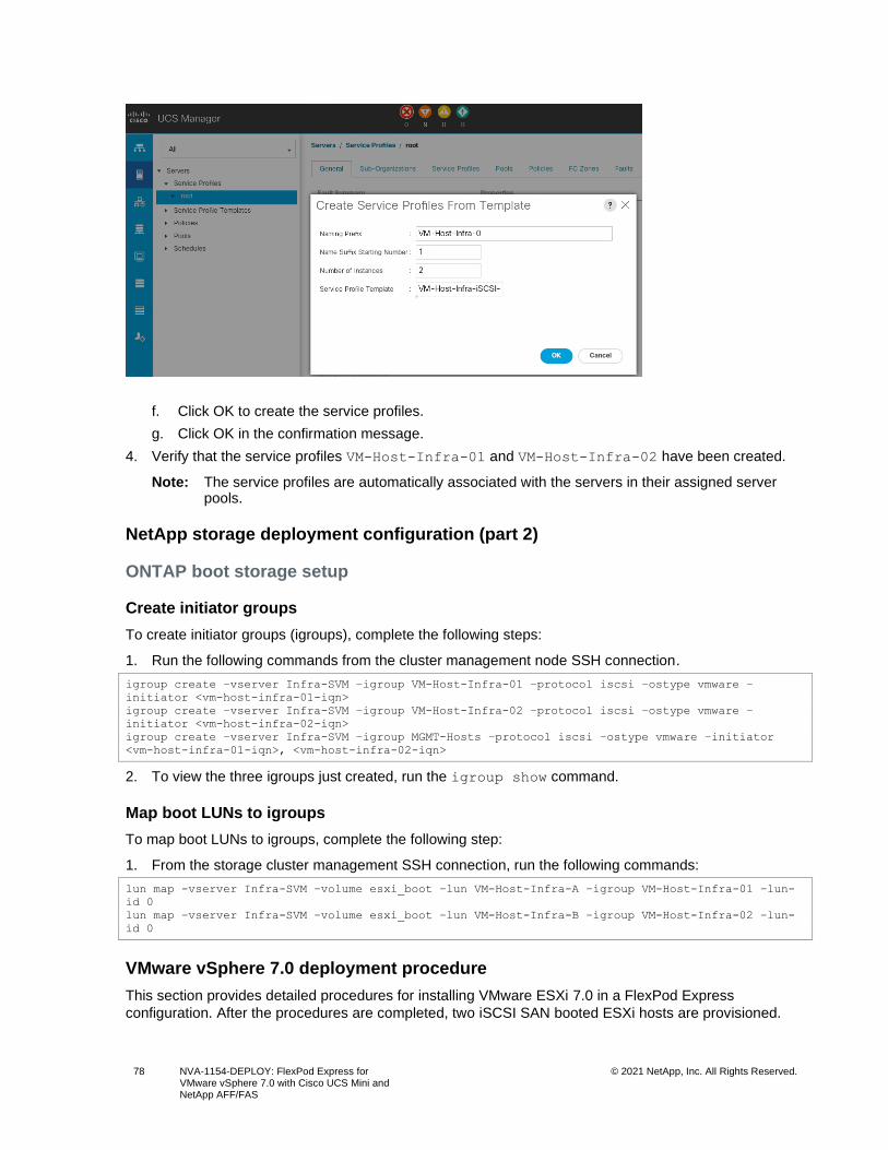
78 NVA-1154-DEPLOY: FlexPod Express for VMware vSphere 7.0 with Cisco UCS Mini and NetApp AFF/FAS
© 2021 NetApp, Inc. All Rights Reserved.
f. Click OK to create the service profiles.
g. Click OK in the confirmation message.
4. Verify that the service profiles VM-Host-Infra-01 and VM-Host-Infra-02 have been created.
Note: The service profiles are automatically associated with the servers in their assigned server pools.
NetApp storage deployment configuration (part 2)
ONTAP boot storage setup
Create initiator groups
To create initiator groups (igroups), complete the following steps:
1. Run the following commands from the cluster management node SSH connection.
igroup create –vserver Infra-SVM –igroup VM-Host-Infra-01 –protocol iscsi –ostype vmware –
initiator <vm-host-infra-01-iqn>
igroup create –vserver Infra-SVM –igroup VM-Host-Infra-02 –protocol iscsi –ostype vmware –
initiator <vm-host-infra-02-iqn>
igroup create –vserver Infra-SVM –igroup MGMT-Hosts –protocol iscsi –ostype vmware –initiator
<vm-host-infra-01-iqn>, <vm-host-infra-02-iqn>
2. To view the three igroups just created, run the igroup show command.
Map boot LUNs to igroups
To map boot LUNs to igroups, complete the following step:
1. From the storage cluster management SSH connection, run the following commands:
lun map -vserver Infra-SVM –volume esxi_boot –lun VM-Host-Infra-A –igroup VM-Host-Infra-01 –lun-
id 0
lun map –vserver Infra-SVM –volume esxi_boot –lun VM-Host-Infra-B –igroup VM-Host-Infra-02 –lun-
id 0
VMware vSphere 7.0 deployment procedure
This section provides detailed procedures for installing VMware ESXi 7.0 in a FlexPod Express
configuration. After the procedures are completed, two iSCSI SAN booted ESXi hosts are provisioned.
79 NVA-1154-DEPLOY: FlexPod Express for VMware vSphere 7.0 with Cisco UCS Mini and NetApp AFF/FAS
© 2021 NetApp, Inc. All Rights Reserved.
Note: VMware recommends a minimum cluster size of three servers. For this validation, the minimum supported cluster size of two servers is used. You can optionally deploy additional servers based on your solution requirements.
Several methods exist for installing ESXi in a VMware environment. These procedures focus on how to
use the built-in KVM console and virtual media features in Cisco UCS Manager to map remote installation
media to individual servers and connect to their boot LUNs.
Download Cisco custom image for ESXi 7.0
If the VMware ESXi custom image has not been downloaded, complete the following steps to complete
the download:
1. Go to the following link: VMware vSphere Hypervisor (ESXi) 7.0
2. You need a user ID and password on vmware.com to download this software.
3. Download the .iso file.
Cisco UCS Manager
The Cisco UCS IP KVM enables the administrator to begin the installation of the operating system
through remote media. It is necessary to log in to the Cisco UCS environment to run the IP KVM.
To log in to the Cisco UCS environment, complete the following steps:
1. Open a web browser and enter the IP address for the Cisco UCS cluster address.
2. Click Launch UCS Manager to launch the UCS Manager GUI.
3. If prompted to accept security certificates, accept, as necessary.
4. When prompted, enter admin as the user name and enter the administrative password.
5. To log in to Cisco UCS Manager, click Login.
6. From the main menu, select Servers.
7. Go to Service Profiles > root > VM-Host-Infra-01.
8. Right-click VM-Host-Infra-01 and select KVM Console.
9. Follow the prompts to launch the Java-based KVM console.
10. Select Servers > Service Profiles > root > VM-Host-Infra-02.
11. Right-click VM-Host-Infra-02. and select KVM Console.
12. Follow the prompts to launch the Java-based KVM console.
Set up VMware ESXi installation
ESXi Hosts VM-Host-Infra-01 and VM-Host-Infra-02
Skip this section if you are using vMedia policies; the ISO file will already be connected to KVM.
To prepare the server for the operating system installation, complete the following steps on each ESXi
host:
1. In the KVM window, click Virtual Media.
2. Click Activate Virtual Devices.
3. If prompted to accept an Unencrypted KVM session, accept, as necessary.
4. Click Virtual Media and select Map CD/DVD.
5. Browse to the ESXi installer ISO image file and click Open.
6. Click Map Device.
7. Click the KVM tab to monitor the server boot.
80 NVA-1154-DEPLOY: FlexPod Express for VMware vSphere 7.0 with Cisco UCS Mini and NetApp AFF/FAS
© 2021 NetApp, Inc. All Rights Reserved.
Install ESXi
ESXi Hosts VM-Host-Infra-01 and VM-Host-Infra-02
To install VMware ESXi to the iSCSI-bootable LUN of the hosts, complete the following steps on each
host:
1. Boot the server by selecting Boot Server and clicking OK. Then click OK again.
2. After reboot, the machine detects the presence of the ESXi installation media. Select the ESXi installer from the boot menu that is displayed.
3. After the installer is finished loading, press Enter to continue with the installation.
4. Read and accept the end-user license agreement (EULA). Press F11 to accept and continue.
5. Select the LUN that was previously set up as the installation disk for ESXi and press Enter to continue with the installation.
6. Select the appropriate keyboard layout and press Enter.
7. Enter and confirm the root password and press Enter.
8. The installer issues a warning that the selected disk will be repartitioned. Press F11 to continue with the installation.
9. After the installation is complete, select the Virtual Media tab and clear the P mark next to the ESXi installation media. Click Yes.
Note: The ESXi installation image must be unmapped to make sure that the server reboots into ESXi and not into the installer.
10. After the installation is complete, press Enter to reboot the server.
11. In Cisco UCS Manager, bind the current service profile to the non-vMedia service profile template to prevent mounting the ESXi installation iso over HTTP.
Set up management networking for ESXi Hosts
Adding a management network for each VMware host is necessary for managing the host. To add a
management network for the VMware hosts, complete the following steps on each ESXi host:
ESXi Host VM-Host-Infra-01 and VM-Host-Infra-02
To configure each ESXi host with access to the management network, complete the following steps:
1. After the server has finished rebooting, press F2 to customize the system.
2. Log in as root, enter the corresponding password, and press Enter to log in.
3. Select Troubleshooting Options and press Enter.
4. Select Enable ESXi Shell and press Enter.
5. Select Enable SSH and press Enter.
6. Press Esc to exit the Troubleshooting Options menu.
7. Select the Configure Management Network option and press Enter.
8. Select Network Adapters and press Enter.
Note: Verify that the numbers in the Hardware Label field match the vmnic numbers in the Device Name field. If the order does not match, use the Consistent Device Naming (CDN) to note which vmnics are mapped to which vNICs and adjust the upcoming procedure accordingly.
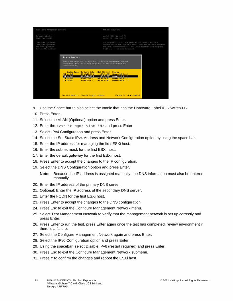
81 NVA-1154-DEPLOY: FlexPod Express for VMware vSphere 7.0 with Cisco UCS Mini and NetApp AFF/FAS
© 2021 NetApp, Inc. All Rights Reserved.
9. Use the Space bar to also select the vmnic that has the Hardware Label 01-vSwitch0-B.
10. Press Enter.
11. Select the VLAN (Optional) option and press Enter.
12. Enter the <var_ib_mgmt_vlan_id> and press Enter.
13. Select IPv4 Configuration and press Enter.
14. Select the Set Static IPv4 Address and Network Configuration option by using the space bar.
15. Enter the IP address for managing the first ESXi host.
16. Enter the subnet mask for the first ESXi host.
17. Enter the default gateway for the first ESXi host.
18. Press Enter to accept the changes to the IP configuration.
19. Select the DNS Configuration option and press Enter.
Note: Because the IP address is assigned manually, the DNS information must also be entered manually.
20. Enter the IP address of the primary DNS server.
21. Optional: Enter the IP address of the secondary DNS server.
22. Enter the FQDN for the first ESXi host.
23. Press Enter to accept the changes to the DNS configuration.
24. Press Esc to exit the Configure Management Network menu.
25. Select Test Management Network to verify that the management network is set up correctly and press Enter.
26. Press Enter to run the test, press Enter again once the test has completed, review environment if there is a failure.
27. Select the Configure Management Network again and press Enter.
28. Select the IPv6 Configuration option and press Enter.
29. Using the spacebar, select Disable IPv6 (restart required) and press Enter.
30. Press Esc to exit the Configure Management Network submenu.
31. Press Y to confirm the changes and reboot the ESXi host.
82 NVA-1154-DEPLOY: FlexPod Express for VMware vSphere 7.0 with Cisco UCS Mini and NetApp AFF/FAS
© 2021 NetApp, Inc. All Rights Reserved.
Reset VMware ESXi host VMkernel port vmk0 MAC address (optional)
ESXi Host VM-Host-Infra-01 and VM-Host-Infra-02
By default, the MAC address of the management VMkernel port vmk0 is the same as the MAC address of
the Ethernet port on which it is placed. If the ESXi host’s boot LUN is remapped to a different server with
different MAC addresses, a MAC address conflict will occur because vmk0 retains the assigned MAC
address unless the ESXi system configuration is reset. To reset the MAC address of vmk0 to a random
VMware-assigned MAC address, complete the following steps:
1. From the ESXi console menu main screen, press Ctrl-Alt-F1 to access the VMware console CLI. In the UCSM KVM, Ctrl-Alt-F1 appears in the list of static macros.
2. Log in as root.
3. Enter esxcfg-vmknic –l to get a detailed listing of interface vmk0. vmk0 should be a part of the
Management Network port group. Note the IP address and network mask of vmk0.
4. To remove vmk0, enter the following command:
esxcfg-vmknic –d “Management Network”
5. To add vmk0 again with a random MAC address, enter the following command:
esxcfg-vmknic –a –i <var_vmk0_ip> -n <var_vmk0_netmask> “Management Network””.
6. Verify that vmk0 has been added again with a random MAC address:
esxcfg-vmknic –l
7. Tag vmk0 as the management interface:
esxcli network ip interface tag add -i vmk0 -t Management
8. When vmk0 was re-added, if a message popped up saying vmk1 was marked as the management interface, remove it by the following command:
esxcli network ip interface tag remove -i vmk1 -t Management
9. Enter exit to log out of the command line interface.
10. Press Ctrl-Alt-F2 to return to the ESXi console menu interface.
Log in to VMware ESXi hosts by using VMware host client
ESXi Host VM-Host-Infra-01
To log in to the VM-Host-Infra-01 ESXi host by using the VMware Host Client, complete the following
steps:
11. Open a web browser on the management workstation and navigate to the VM-Host-Infra-01
management IP address.
12. Click Open the VMware Host Client.
13. Enter root for the user name.
14. Enter the root password.
15. Click Login to connect.
16. Repeat this process to log in to VM-Host-Infra-02 in a separate browser tab or window.
Install VMware driver for Cisco Virtual Interface Card (VIC) and NFS Plug-in
ESXi Hosts VM-Host-Infra-01, VM-Host-Infra-02
Download and extract the offline bundle for the following VMware VIC driver to the management
workstation:
83 NVA-1154-DEPLOY: FlexPod Express for VMware vSphere 7.0 with Cisco UCS Mini and NetApp AFF/FAS
© 2021 NetApp, Inc. All Rights Reserved.
• nenic Driver version 1.0.33.0
Note: The VMware ESXi 7.0 Cisco Custom ISO contains the nenic driver version 1.0.33.0. It is not necessary to download or update the nenic driver, but the commands are left here to be used for future updates.
Download the NetApp NFS Plug-in for VMware VAAI to the management workstation:
• NFS Plug-in version 1.1.2
To install VMware VIC Driver and NFS Plug-in on the ESXi host VM-Host-Infra-01 and VM-Host-Infra-02,
follow these steps:
1. Using an SCP program such as WinSCP, copy the offline bundles referenced above to the /tmp directory on each ESXi host.
2. Using a secure shell (SSH) tool such as PuTTY, SSH to each VMware ESXi host. Log in as root with the root password.
3. Enter cd /tmp.
4. Run the following commands on each host:
esxcli software vib update -d /tmp/Cisco-nenic_1.0.33.0-1OEM.670.0.0.8169922-offline_bundle-
16216785.zip
esxcli software vib install -d /tmp/NetAppNasPlugin.v23.zip
reboot
Set Up VMkernel ports and virtual switch
ESXi Host VM-Host-Infra-01 and VM-Host-Infra-02
To set up the VMkernel ports and the virtual switches on the ESXi hosts, complete the following steps.
1. From the Host Client, select Networking on the left.
2. In the center pane, select the Virtual Switches tab.
3. Select vSwitch0.
4. Select Edit settings.
5. Change the MTU to 9000.
6. Expand NIC teaming.
7. In the Failover Order section, select the vmnic that has the Standby status and click Mark Active.
8. Verify that both vmnic now have the status of Active.
9. Click Save.
10. Select Networking on the left.
11. In the center pane, select the Virtual switches tab.
12. Select iScsiBootvSwitch.
13. Select Edit settings.
14. Change the MTU to 9000
15. Click Save.
16. Select Networking on the left.
17. In the center pane, select the VMkernel NICs tab.
18. Select vmk1 iScsiBootPG.
19. Select Edit settings.

84 NVA-1154-DEPLOY: FlexPod Express for VMware vSphere 7.0 with Cisco UCS Mini and NetApp AFF/FAS
© 2021 NetApp, Inc. All Rights Reserved.
20. Change the MTU to 9000.
21. Expand IPv4 settings and change the IP address to an address outside of the UCS iSCSI-IP-Pool-A.
Note: To avoid IP address conflicts if the Cisco UCS iSCSI IP Pool addresses should get reassigned, it is recommended to use different IP addresses in the same subnet for the iSCSI VMkernel ports.
22. Click Save.
23. Select Networking on the left.
24. In the center pan, select the Virtual switches tab.
25. Select the Add standard virtual switch.
26. Provide a name of iScsciBootvSwitch-B for the vSwitch Name.
27. Set the MTU to 9000.
28. Select vmnic3 from the Uplink 1 drop-down menu.
Note: Select the vmnic that has hardware label of 03-iSCSI-B. (See the ESXi host configuration section earlier.)
29. Click Add.
30. In the center pane, select the VMkernel NICs tab.
31. Select Add VMkernel NIC
32. Specify a new port group name of iScsiBootPG-B.
33. Select iScsciBootvSwitch-B for Virtual switch.
34. Set the MTU to 9000. Do not enter a VLAN ID.
35. Select Static for the IPv4 settings and expand the option to provide the Address and Subnet Mask within the configuration.
Note: To avoid IP address conflicts, if the Cisco UCS iSCSI IP Pool addresses should get reassigned, it is recommended to use different IP addresses in the same subnet for the iSCSI VMkernel ports.
36. Click Create.
37. Go to Networking >Port Groups.
38. Right click on the VM network port group and select Edit Settings.
39. Enter <var_vmtraffic_vlan_id> for the VLAN ID.
40. Click Save.
41. In the center pane, select the VMkernel NICs tab.
42. Click Add VMkernel NIC.
43. For New port group, enter vMotion.
44. For Virtual switch, select vSwitch0 selected.
45. Enter <var_vmotion_vlan_id> for the VLAN ID.
46. Change the MTU to 9000.
47. Select Static IPv4 settings and expand IPv4 settings.
48. Enter the ESXi host vMotion IP address and netmask.
49. Select the vMotion stack for TCP/IP stack.
50. The vMotion Services will be selected automatically.
51. Click Create.
52. Click Add VMkernel NIC.
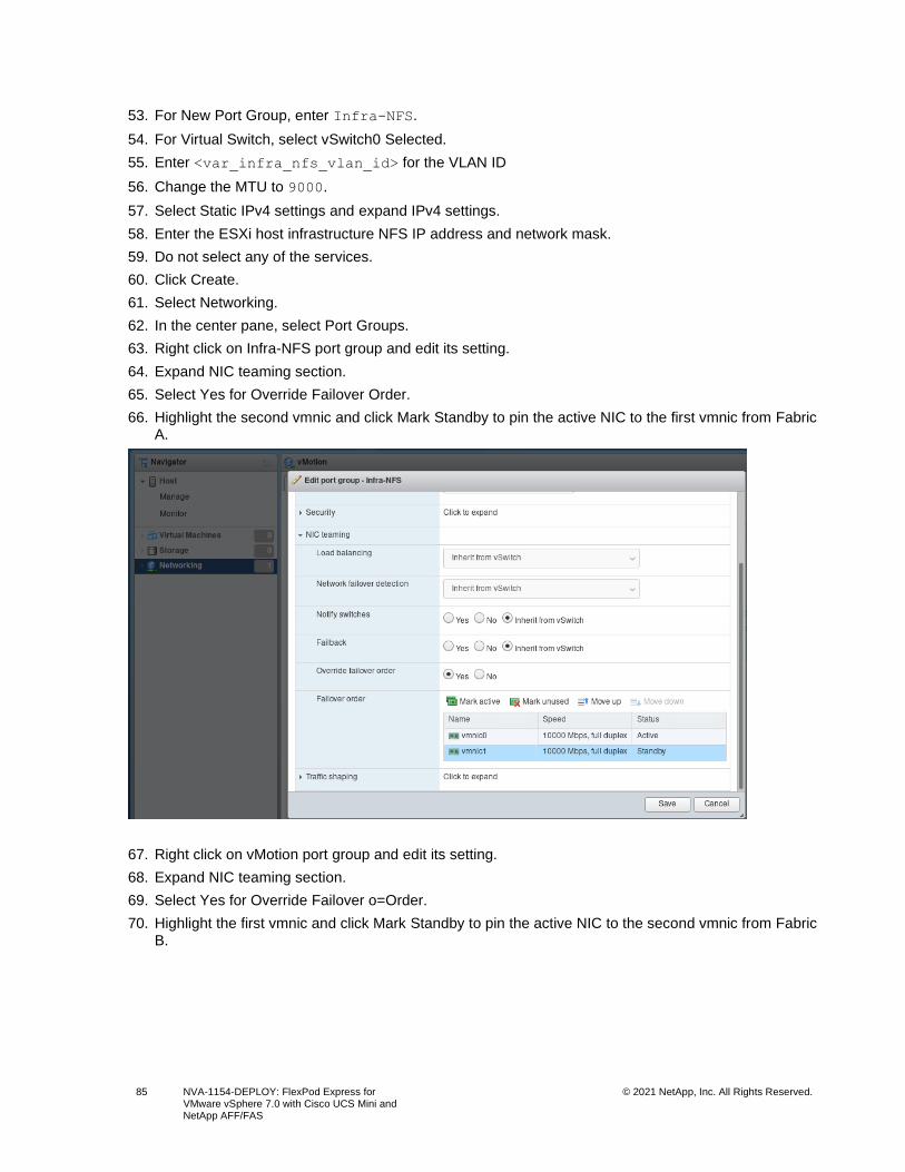
85 NVA-1154-DEPLOY: FlexPod Express for VMware vSphere 7.0 with Cisco UCS Mini and NetApp AFF/FAS
© 2021 NetApp, Inc. All Rights Reserved.
53. For New Port Group, enter Infra-NFS.
54. For Virtual Switch, select vSwitch0 Selected.
55. Enter <var_infra_nfs_vlan_id> for the VLAN ID
56. Change the MTU to 9000.
57. Select Static IPv4 settings and expand IPv4 settings.
58. Enter the ESXi host infrastructure NFS IP address and network mask.
59. Do not select any of the services.
60. Click Create.
61. Select Networking.
62. In the center pane, select Port Groups.
63. Right click on Infra-NFS port group and edit its setting.
64. Expand NIC teaming section.
65. Select Yes for Override Failover Order.
66. Highlight the second vmnic and click Mark Standby to pin the active NIC to the first vmnic from Fabric A.
67. Right click on vMotion port group and edit its setting.
68. Expand NIC teaming section.
69. Select Yes for Override Failover o=Order.
70. Highlight the first vmnic and click Mark Standby to pin the active NIC to the second vmnic from Fabric B.
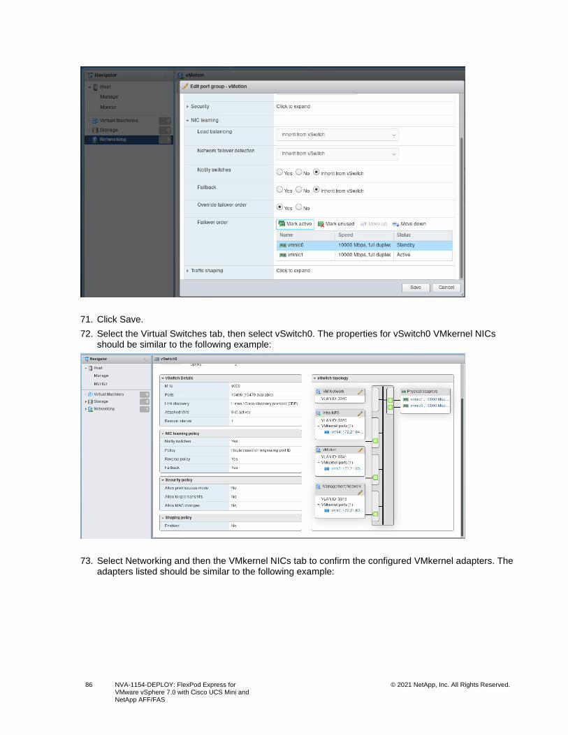
86 NVA-1154-DEPLOY: FlexPod Express for VMware vSphere 7.0 with Cisco UCS Mini and NetApp AFF/FAS
© 2021 NetApp, Inc. All Rights Reserved.
71. Click Save.
72. Select the Virtual Switches tab, then select vSwitch0. The properties for vSwitch0 VMkernel NICs should be similar to the following example:
73. Select Networking and then the VMkernel NICs tab to confirm the configured VMkernel adapters. The adapters listed should be similar to the following example:
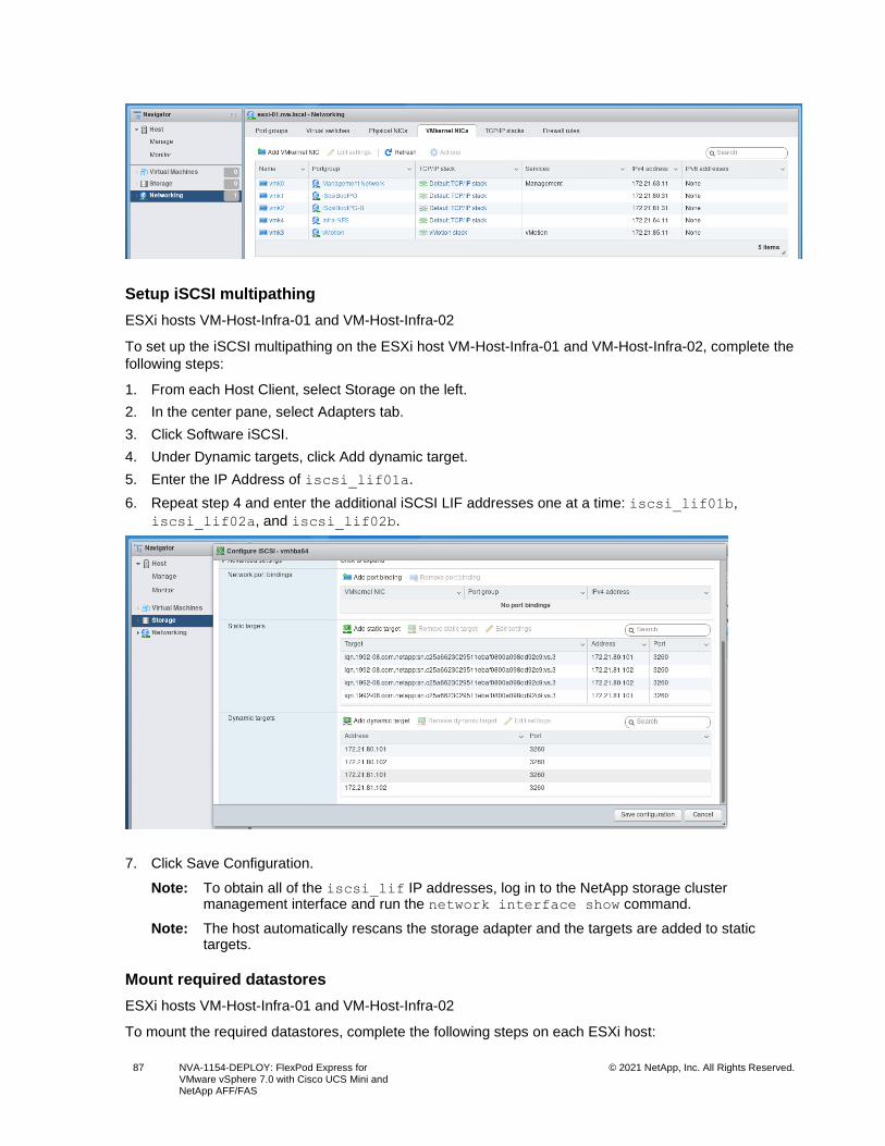
87 NVA-1154-DEPLOY: FlexPod Express for VMware vSphere 7.0 with Cisco UCS Mini and NetApp AFF/FAS
© 2021 NetApp, Inc. All Rights Reserved.
Setup iSCSI multipathing
ESXi hosts VM-Host-Infra-01 and VM-Host-Infra-02
To set up the iSCSI multipathing on the ESXi host VM-Host-Infra-01 and VM-Host-Infra-02, complete the
following steps:
1. From each Host Client, select Storage on the left.
2. In the center pane, select Adapters tab.
3. Click Software iSCSI.
4. Under Dynamic targets, click Add dynamic target.
5. Enter the IP Address of iscsi_lif01a.
6. Repeat step 4 and enter the additional iSCSI LIF addresses one at a time: iscsi_lif01b,
iscsi_lif02a, and iscsi_lif02b.
7. Click Save Configuration.
Note: To obtain all of the iscsi_lif IP addresses, log in to the NetApp storage cluster management interface and run the network interface show command.
Note: The host automatically rescans the storage adapter and the targets are added to static targets.
Mount required datastores
ESXi hosts VM-Host-Infra-01 and VM-Host-Infra-02
To mount the required datastores, complete the following steps on each ESXi host:
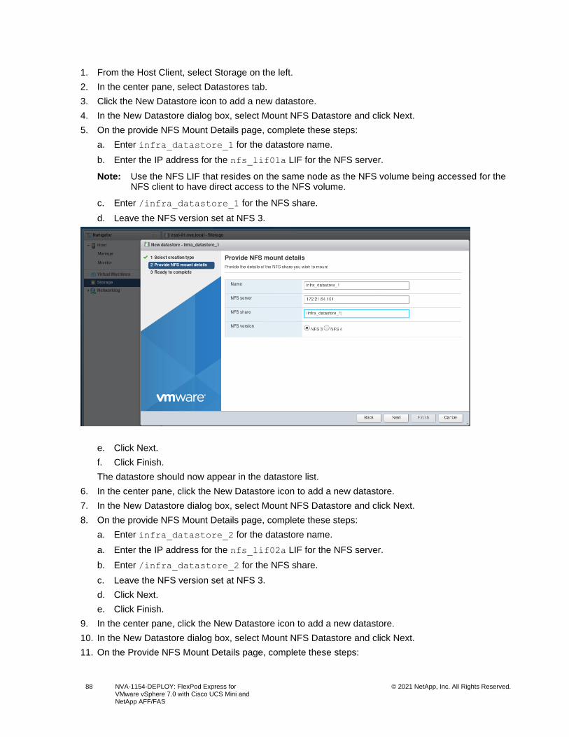
88 NVA-1154-DEPLOY: FlexPod Express for VMware vSphere 7.0 with Cisco UCS Mini and NetApp AFF/FAS
© 2021 NetApp, Inc. All Rights Reserved.
1. From the Host Client, select Storage on the left.
2. In the center pane, select Datastores tab.
3. Click the New Datastore icon to add a new datastore.
4. In the New Datastore dialog box, select Mount NFS Datastore and click Next.
5. On the provide NFS Mount Details page, complete these steps:
a. Enter infra_datastore_1 for the datastore name.
b. Enter the IP address for the nfs_lif01a LIF for the NFS server.
Note: Use the NFS LIF that resides on the same node as the NFS volume being accessed for the NFS client to have direct access to the NFS volume.
c. Enter /infra_datastore_1 for the NFS share.
d. Leave the NFS version set at NFS 3.
e. Click Next.
f. Click Finish.
The datastore should now appear in the datastore list.
6. In the center pane, click the New Datastore icon to add a new datastore.
7. In the New Datastore dialog box, select Mount NFS Datastore and click Next.
8. On the provide NFS Mount Details page, complete these steps:
a. Enter infra_datastore_2 for the datastore name.
a. Enter the IP address for the nfs_lif02a LIF for the NFS server.
b. Enter /infra_datastore_2 for the NFS share.
c. Leave the NFS version set at NFS 3.
d. Click Next.
e. Click Finish.
9. In the center pane, click the New Datastore icon to add a new datastore.
10. In the New Datastore dialog box, select Mount NFS Datastore and click Next.
11. On the Provide NFS Mount Details page, complete these steps:
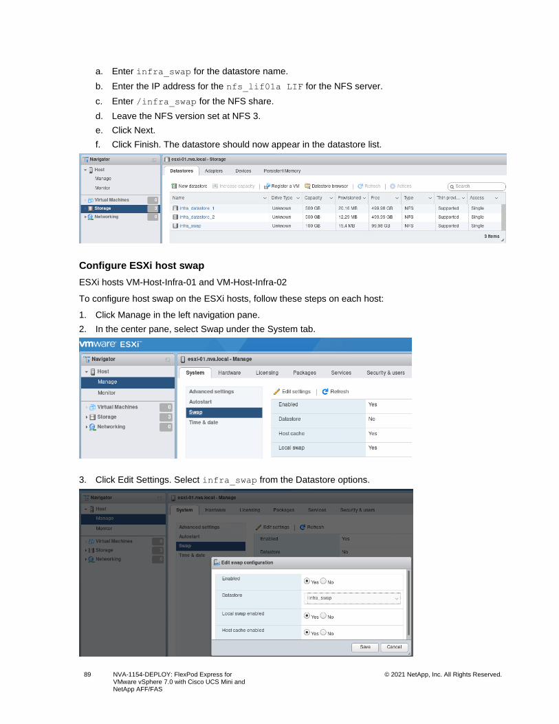
89 NVA-1154-DEPLOY: FlexPod Express for VMware vSphere 7.0 with Cisco UCS Mini and NetApp AFF/FAS
© 2021 NetApp, Inc. All Rights Reserved.
a. Enter infra_swap for the datastore name.
b. Enter the IP address for the nfs_lif01a LIF for the NFS server.
c. Enter /infra_swap for the NFS share.
d. Leave the NFS version set at NFS 3.
e. Click Next.
f. Click Finish. The datastore should now appear in the datastore list.
Configure ESXi host swap
ESXi hosts VM-Host-Infra-01 and VM-Host-Infra-02
To configure host swap on the ESXi hosts, follow these steps on each host:
1. Click Manage in the left navigation pane.
2. In the center pane, select Swap under the System tab.
3. Click Edit Settings. Select infra_swap from the Datastore options.
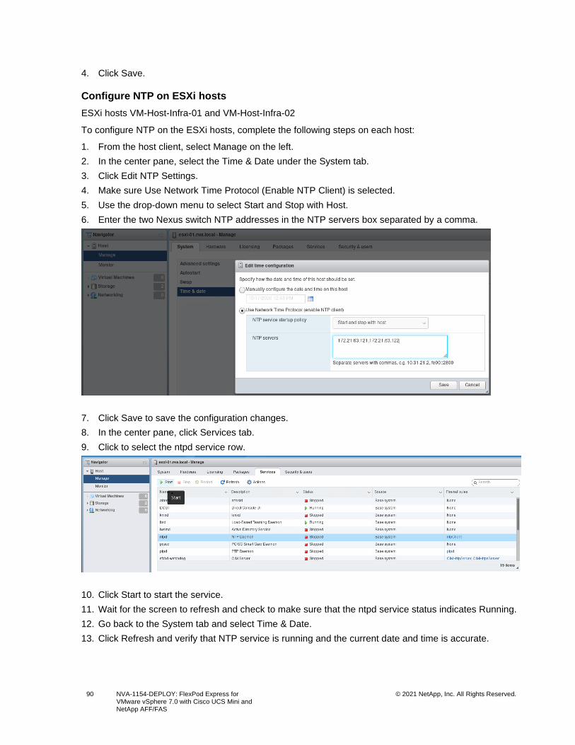
90 NVA-1154-DEPLOY: FlexPod Express for VMware vSphere 7.0 with Cisco UCS Mini and NetApp AFF/FAS
© 2021 NetApp, Inc. All Rights Reserved.
4. Click Save.
Configure NTP on ESXi hosts
ESXi hosts VM-Host-Infra-01 and VM-Host-Infra-02
To configure NTP on the ESXi hosts, complete the following steps on each host:
1. From the host client, select Manage on the left.
2. In the center pane, select the Time & Date under the System tab.
3. Click Edit NTP Settings.
4. Make sure Use Network Time Protocol (Enable NTP Client) is selected.
5. Use the drop-down menu to select Start and Stop with Host.
6. Enter the two Nexus switch NTP addresses in the NTP servers box separated by a comma.
7. Click Save to save the configuration changes.
8. In the center pane, click Services tab.
9. Click to select the ntpd service row.
10. Click Start to start the service.
11. Wait for the screen to refresh and check to make sure that the ntpd service status indicates Running.
12. Go back to the System tab and select Time & Date.
13. Click Refresh and verify that NTP service is running and the current date and time is accurate.
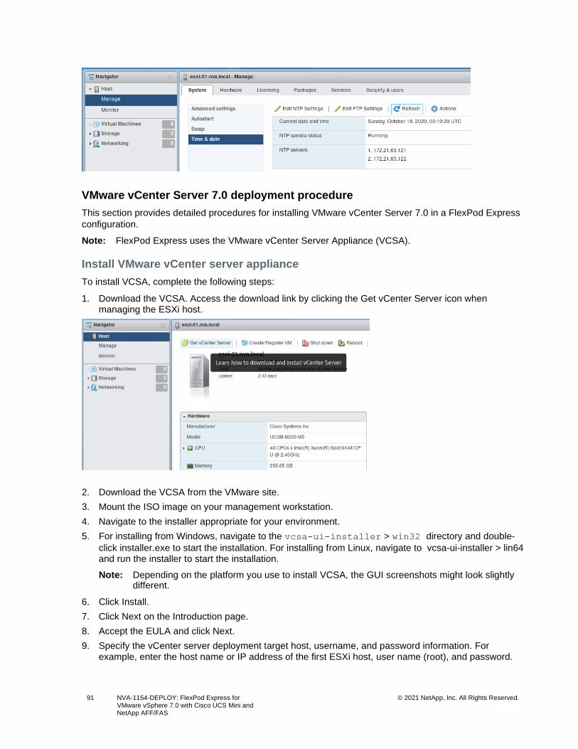
91 NVA-1154-DEPLOY: FlexPod Express for VMware vSphere 7.0 with Cisco UCS Mini and NetApp AFF/FAS
© 2021 NetApp, Inc. All Rights Reserved.
VMware vCenter Server 7.0 deployment procedure
This section provides detailed procedures for installing VMware vCenter Server 7.0 in a FlexPod Express
configuration.
Note: FlexPod Express uses the VMware vCenter Server Appliance (VCSA).
Install VMware vCenter server appliance
To install VCSA, complete the following steps:
1. Download the VCSA. Access the download link by clicking the Get vCenter Server icon when managing the ESXi host.
2. Download the VCSA from the VMware site.
3. Mount the ISO image on your management workstation.
4. Navigate to the installer appropriate for your environment.
5. For installing from Windows, navigate to the vcsa-ui-installer > win32 directory and double-
click installer.exe to start the installation. For installing from Linux, navigate to vcsa-ui-installer > lin64 and run the installer to start the installation.
Note: Depending on the platform you use to install VCSA, the GUI screenshots might look slightly different.
6. Click Install.
7. Click Next on the Introduction page.
8. Accept the EULA and click Next.
9. Specify the vCenter server deployment target host, username, and password information. For example, enter the host name or IP address of the first ESXi host, user name (root), and password.
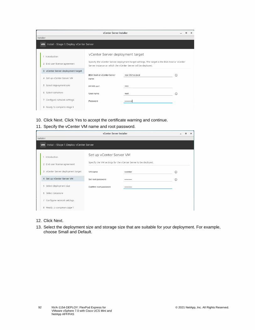
92 NVA-1154-DEPLOY: FlexPod Express for VMware vSphere 7.0 with Cisco UCS Mini and NetApp AFF/FAS
© 2021 NetApp, Inc. All Rights Reserved.
10. Click Next. Click Yes to accept the certificate warning and continue.
11. Specify the vCenter VM name and root password.
12. Click Next.
13. Select the deployment size and storage size that are suitable for your deployment. For example, choose Small and Default.
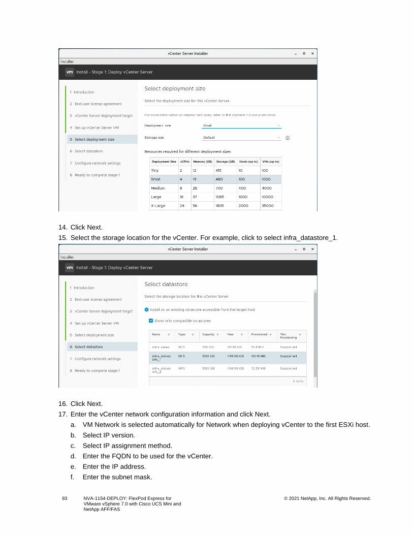
93 NVA-1154-DEPLOY: FlexPod Express for VMware vSphere 7.0 with Cisco UCS Mini and NetApp AFF/FAS
© 2021 NetApp, Inc. All Rights Reserved.
14. Click Next.
15. Select the storage location for the vCenter. For example, click to select infra_datastore_1.
16. Click Next.
17. Enter the vCenter network configuration information and click Next.
a. VM Network is selected automatically for Network when deploying vCenter to the first ESXi host.
b. Select IP version.
c. Select IP assignment method.
d. Enter the FQDN to be used for the vCenter.
e. Enter the IP address.
f. Enter the subnet mask.
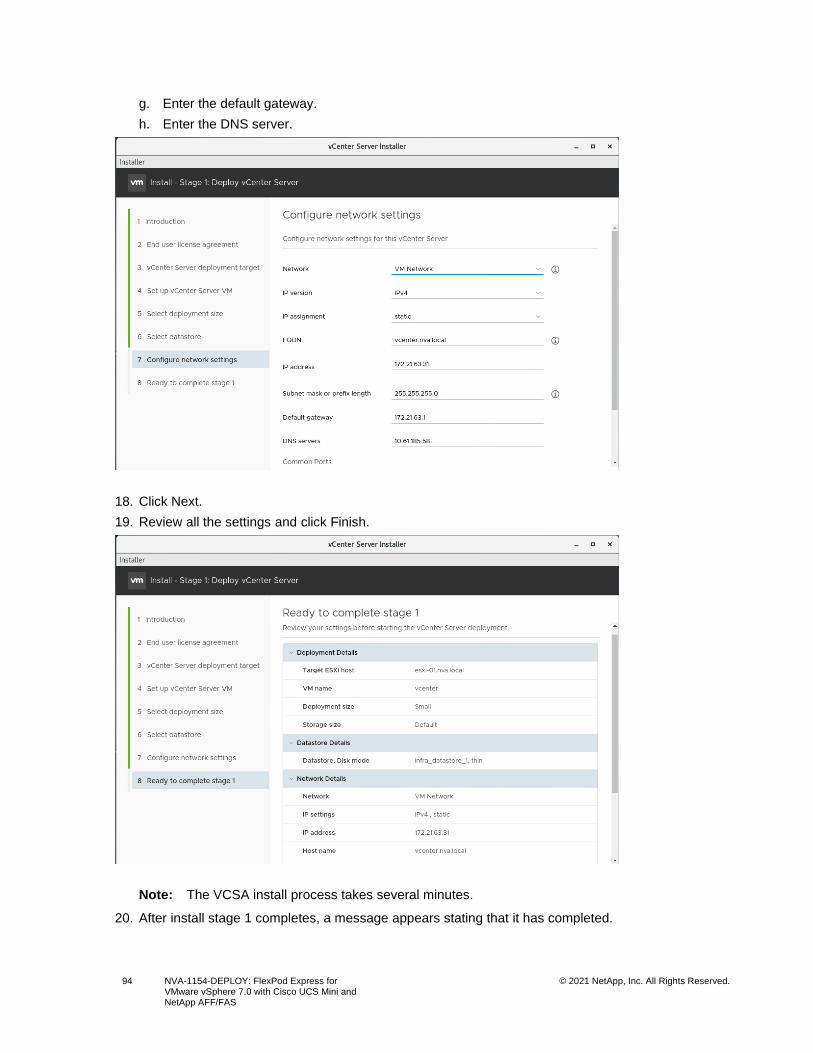
94 NVA-1154-DEPLOY: FlexPod Express for VMware vSphere 7.0 with Cisco UCS Mini and NetApp AFF/FAS
© 2021 NetApp, Inc. All Rights Reserved.
g. Enter the default gateway.
h. Enter the DNS server.
18. Click Next.
19. Review all the settings and click Finish.
Note: The VCSA install process takes several minutes.
20. After install stage 1 completes, a message appears stating that it has completed.
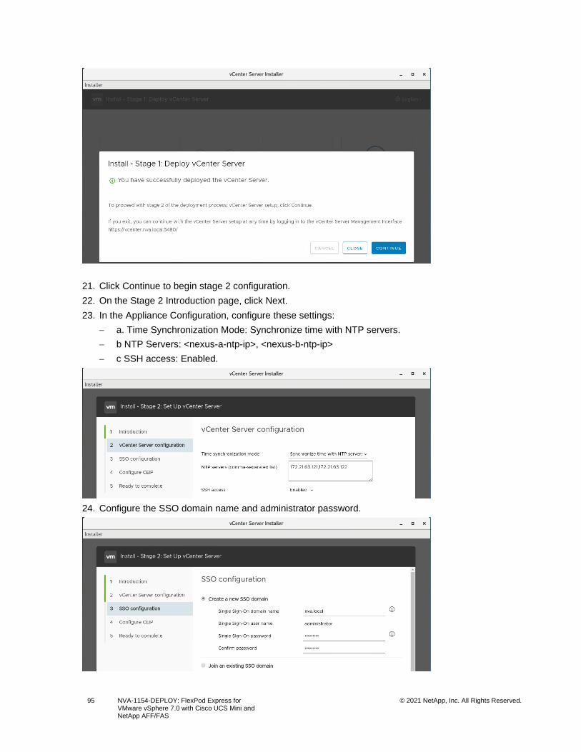
95 NVA-1154-DEPLOY: FlexPod Express for VMware vSphere 7.0 with Cisco UCS Mini and NetApp AFF/FAS
© 2021 NetApp, Inc. All Rights Reserved.
21. Click Continue to begin stage 2 configuration.
22. On the Stage 2 Introduction page, click Next.
23. In the Appliance Configuration, configure these settings:
− a. Time Synchronization Mode: Synchronize time with NTP servers.
− b NTP Servers: <nexus-a-ntp-ip>, <nexus-b-ntp-ip>
− c SSH access: Enabled.
24. Configure the SSO domain name and administrator password.
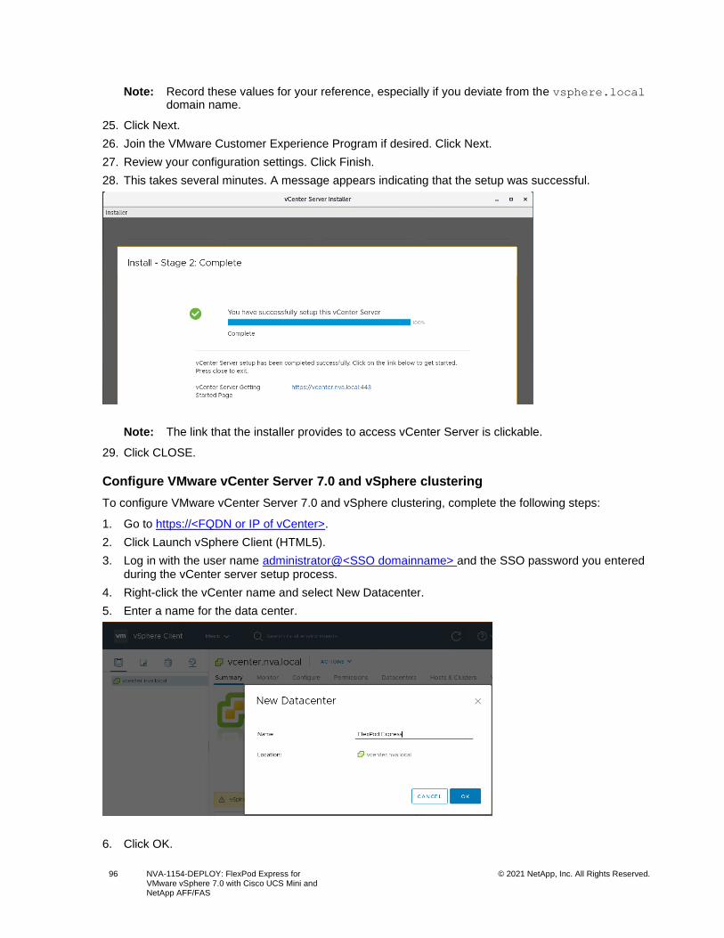
96 NVA-1154-DEPLOY: FlexPod Express for VMware vSphere 7.0 with Cisco UCS Mini and NetApp AFF/FAS
© 2021 NetApp, Inc. All Rights Reserved.
Note: Record these values for your reference, especially if you deviate from the vsphere.local domain name.
25. Click Next.
26. Join the VMware Customer Experience Program if desired. Click Next.
27. Review your configuration settings. Click Finish.
28. This takes several minutes. A message appears indicating that the setup was successful.
Note: The link that the installer provides to access vCenter Server is clickable.
29. Click CLOSE.
Configure VMware vCenter Server 7.0 and vSphere clustering
To configure VMware vCenter Server 7.0 and vSphere clustering, complete the following steps:
1. Go to https://<FQDN or IP of vCenter>.
2. Click Launch vSphere Client (HTML5).
3. Log in with the user name administrator@<SSO domainname> and the SSO password you entered during the vCenter server setup process.
4. Right-click the vCenter name and select New Datacenter.
5. Enter a name for the data center.
6. Click OK.
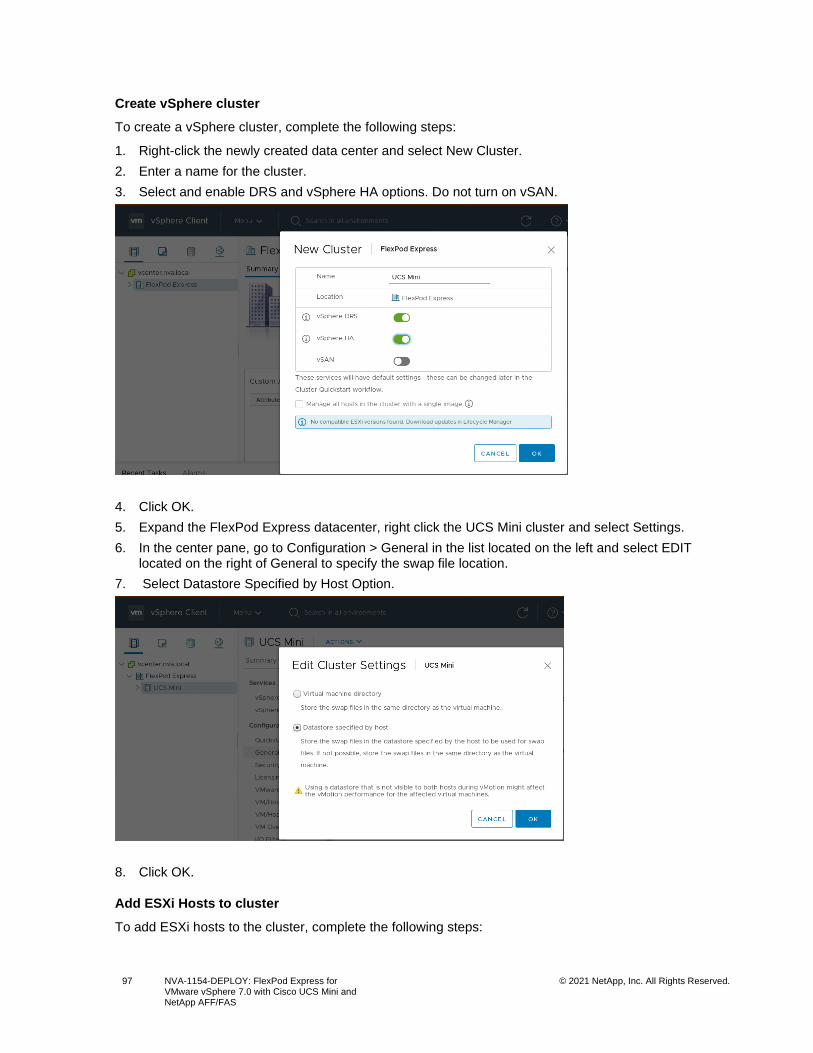
97 NVA-1154-DEPLOY: FlexPod Express for VMware vSphere 7.0 with Cisco UCS Mini and NetApp AFF/FAS
© 2021 NetApp, Inc. All Rights Reserved.
Create vSphere cluster
To create a vSphere cluster, complete the following steps:
1. Right-click the newly created data center and select New Cluster.
2. Enter a name for the cluster.
3. Select and enable DRS and vSphere HA options. Do not turn on vSAN.
4. Click OK.
5. Expand the FlexPod Express datacenter, right click the UCS Mini cluster and select Settings.
6. In the center pane, go to Configuration > General in the list located on the left and select EDIT located on the right of General to specify the swap file location.
7. Select Datastore Specified by Host Option.
8. Click OK.
Add ESXi Hosts to cluster
To add ESXi hosts to the cluster, complete the following steps:
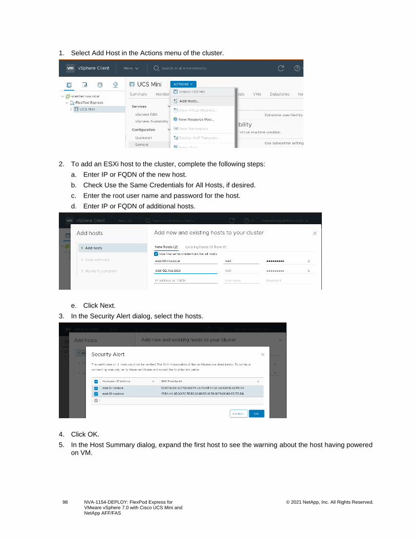
98 NVA-1154-DEPLOY: FlexPod Express for VMware vSphere 7.0 with Cisco UCS Mini and NetApp AFF/FAS
© 2021 NetApp, Inc. All Rights Reserved.
1. Select Add Host in the Actions menu of the cluster.
2. To add an ESXi host to the cluster, complete the following steps:
a. Enter IP or FQDN of the new host.
b. Check Use the Same Credentials for All Hosts, if desired.
c. Enter the root user name and password for the host.
d. Enter IP or FQDN of additional hosts.
e. Click Next.
3. In the Security Alert dialog, select the hosts.
4. Click OK.
5. In the Host Summary dialog, expand the first host to see the warning about the host having powered on VM.
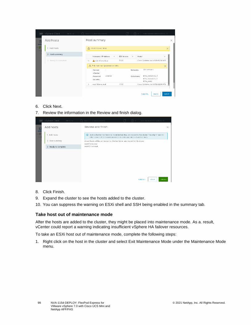
99 NVA-1154-DEPLOY: FlexPod Express for VMware vSphere 7.0 with Cisco UCS Mini and NetApp AFF/FAS
© 2021 NetApp, Inc. All Rights Reserved.
6. Click Next.
7. Review the information in the Review and finish dialog.
8. Click Finish.
9. Expand the cluster to see the hosts added to the cluster.
10. You can suppress the warning on ESXi shell and SSH being enabled in the summary tab.
Take host out of maintenance mode
After the hosts are added to the cluster, they might be placed into maintenance mode. As a. result,
vCenter could report a warning indicating insufficient vSphere HA failover resources.
To take an ESXi host out of maintenance mode, complete the following steps:
1. Right click on the host in the cluster and select Exit Maintenance Mode under the Maintenance Mode menu.
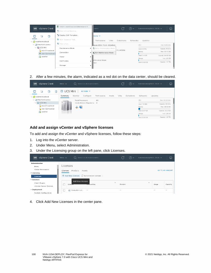
100 NVA-1154-DEPLOY: FlexPod Express for VMware vSphere 7.0 with Cisco UCS Mini and NetApp AFF/FAS
© 2021 NetApp, Inc. All Rights Reserved.
2. After a few minutes, the alarm, indicated as a red dot on the data center, should be cleared.
Add and assign vCenter and vSphere licenses
To add and assign the vCenter and vSphere licenses, follow these steps:
1. Log into the vCenter server.
2. Under Menu, select Administration.
3. Under the Licensing group on the left pane, click Licenses.
4. Click Add New Licenses in the center pane.
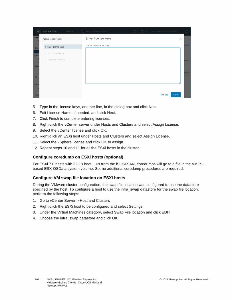
101 NVA-1154-DEPLOY: FlexPod Express for VMware vSphere 7.0 with Cisco UCS Mini and NetApp AFF/FAS
© 2021 NetApp, Inc. All Rights Reserved.
5. Type in the license keys, one per line, in the dialog box and click Next.
6. Edit License Name, if needed, and click Next.
7. Click Finish to complete entering licenses.
8. Right-click the vCenter server under Hosts and Clusters and select Assign License.
9. Select the vCenter license and click OK.
10. Right-click an ESXi host under Hosts and Clusters and select Assign License.
11. Select the vSphere license and click OK to assign.
12. Repeat steps 10 and 11 for all the ESXi hosts in the cluster.
Configure coredump on ESXi hosts (optional)
For ESXi 7.0 hosts with 32GB boot LUN from the iSCSI SAN, coredumps will go to a file in the VMFS-L
based ESX-OSData system volume. So, no additional coredump procedures are required.
Configure VM swap file location on ESXi hosts
During the VMware cluster configuration, the swap file location was configured to use the datastore
specified by the host. To configure a host to use the infra_swap datastore for the swap file location,
perform the following steps:
1. Go to vCenter Server > Host and Clusters
2. Right-click the ESXi host to be configured and select Settings.
3. Under the Virtual Machines category, select Swap File location and click EDIT.
4. Choose the infra_swap datastore and click OK.
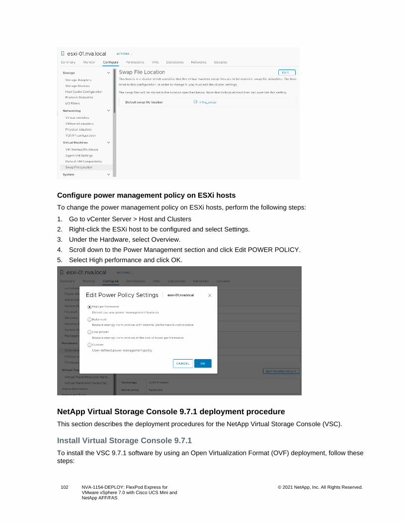
102 NVA-1154-DEPLOY: FlexPod Express for VMware vSphere 7.0 with Cisco UCS Mini and NetApp AFF/FAS
© 2021 NetApp, Inc. All Rights Reserved.
Configure power management policy on ESXi hosts
To change the power management policy on ESXi hosts, perform the following steps:
1. Go to vCenter Server > Host and Clusters
2. Right-click the ESXi host to be configured and select Settings.
3. Under the Hardware, select Overview.
4. Scroll down to the Power Management section and click Edit POWER POLICY.
5. Select High performance and click OK.
NetApp Virtual Storage Console 9.7.1 deployment procedure
This section describes the deployment procedures for the NetApp Virtual Storage Console (VSC).
Install Virtual Storage Console 9.7.1
To install the VSC 9.7.1 software by using an Open Virtualization Format (OVF) deployment, follow these
steps:
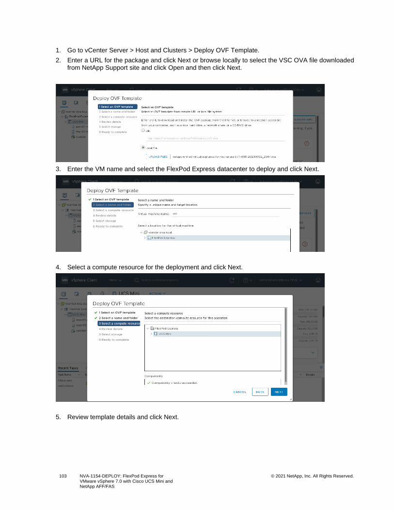
103 NVA-1154-DEPLOY: FlexPod Express for VMware vSphere 7.0 with Cisco UCS Mini and NetApp AFF/FAS
© 2021 NetApp, Inc. All Rights Reserved.
1. Go to vCenter Server > Host and Clusters > Deploy OVF Template.
2. Enter a URL for the package and click Next or browse locally to select the VSC OVA file downloaded from NetApp Support site and click Open and then click Next.
3. Enter the VM name and select the FlexPod Express datacenter to deploy and click Next.
4. Select a compute resource for the deployment and click Next.
5. Review template details and click Next.
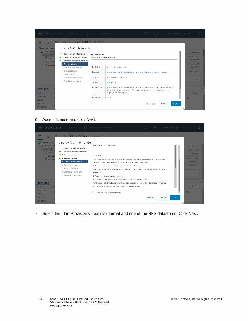
104 NVA-1154-DEPLOY: FlexPod Express for VMware vSphere 7.0 with Cisco UCS Mini and NetApp AFF/FAS
© 2021 NetApp, Inc. All Rights Reserved.
6. Accept license and click Next.
7. Select the Thin Provision virtual disk format and one of the NFS datastores. Click Next.
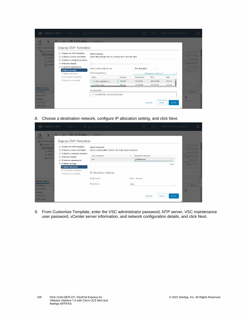
105 NVA-1154-DEPLOY: FlexPod Express for VMware vSphere 7.0 with Cisco UCS Mini and NetApp AFF/FAS
© 2021 NetApp, Inc. All Rights Reserved.
8. Choose a destination network, configure IP allocation setting, and click Next.
9. From Customize Template, enter the VSC administrator password, NTP server, VSC maintenance user password, vCenter server information, and network configuration details, and click Next.
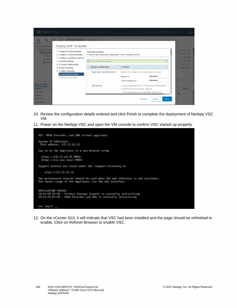
106 NVA-1154-DEPLOY: FlexPod Express for VMware vSphere 7.0 with Cisco UCS Mini and NetApp AFF/FAS
© 2021 NetApp, Inc. All Rights Reserved.
10. Review the configuration details entered and click Finish to complete the deployment of NetApp VSC VM.
11. Power on the NetApp VSC and open the VM console to confirm VSC started up properly.
12. On the vCenter GUI, it will indicate that VSC had been installed and the page should be refreshed to enable. Click on Refresh Browser to enable VSC.
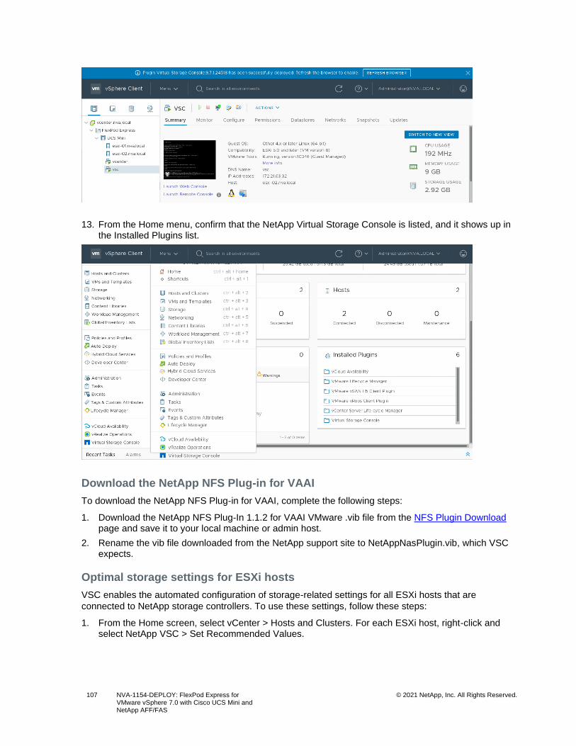
107 NVA-1154-DEPLOY: FlexPod Express for VMware vSphere 7.0 with Cisco UCS Mini and NetApp AFF/FAS
© 2021 NetApp, Inc. All Rights Reserved.
13. From the Home menu, confirm that the NetApp Virtual Storage Console is listed, and it shows up in the Installed Plugins list.
Download the NetApp NFS Plug-in for VAAI
To download the NetApp NFS Plug-in for VAAI, complete the following steps:
1. Download the NetApp NFS Plug-In 1.1.2 for VAAI VMware .vib file from the NFS Plugin Download page and save it to your local machine or admin host.
2. Rename the vib file downloaded from the NetApp support site to NetAppNasPlugin.vib, which VSC expects.
Optimal storage settings for ESXi hosts
VSC enables the automated configuration of storage-related settings for all ESXi hosts that are
connected to NetApp storage controllers. To use these settings, follow these steps:
1. From the Home screen, select vCenter > Hosts and Clusters. For each ESXi host, right-click and select NetApp VSC > Set Recommended Values.
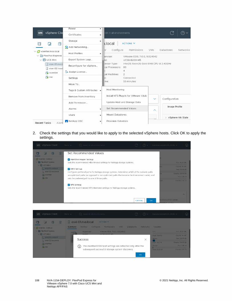
108 NVA-1154-DEPLOY: FlexPod Express for VMware vSphere 7.0 with Cisco UCS Mini and NetApp AFF/FAS
© 2021 NetApp, Inc. All Rights Reserved.
2. Check the settings that you would like to apply to the selected vSphere hosts. Click OK to apply the settings.
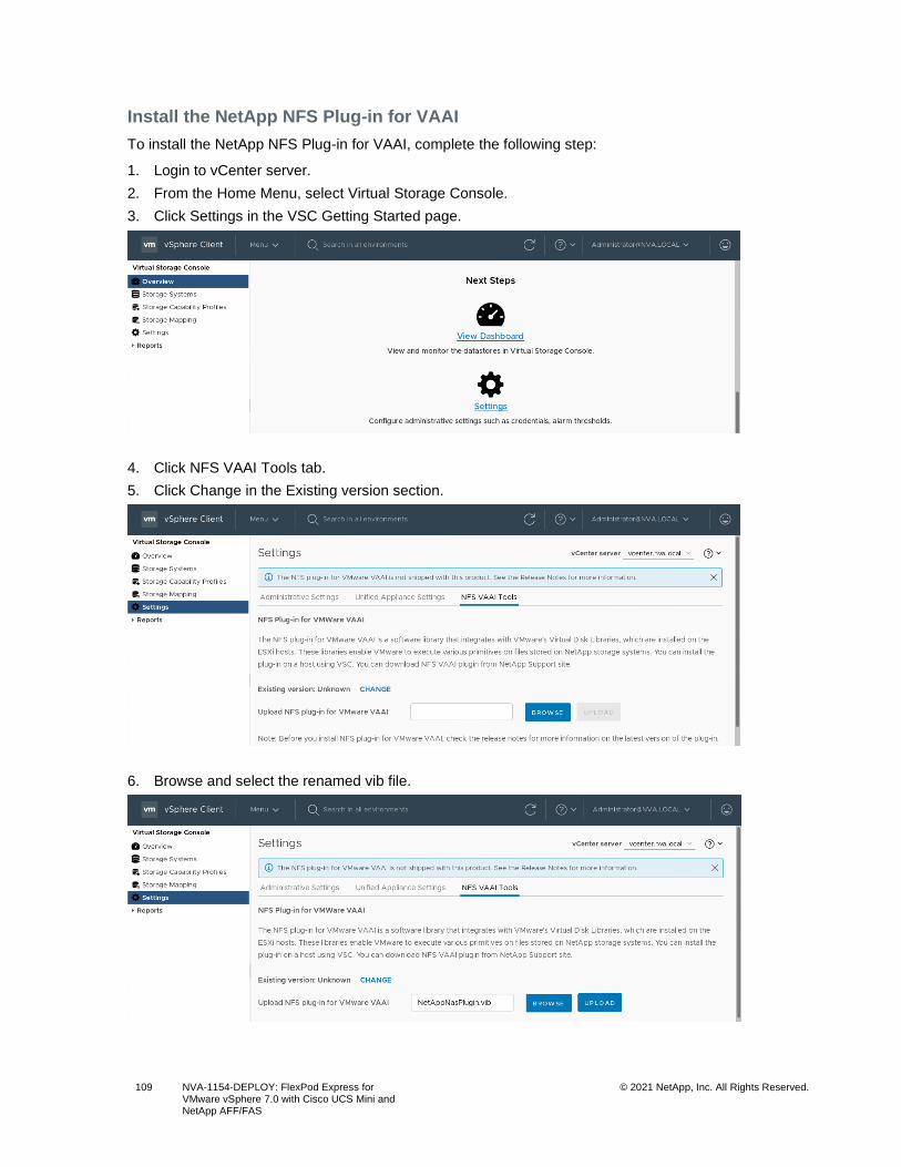
109 NVA-1154-DEPLOY: FlexPod Express for VMware vSphere 7.0 with Cisco UCS Mini and NetApp AFF/FAS
© 2021 NetApp, Inc. All Rights Reserved.
Install the NetApp NFS Plug-in for VAAI
To install the NetApp NFS Plug-in for VAAI, complete the following step:
1. Login to vCenter server.
2. From the Home Menu, select Virtual Storage Console.
3. Click Settings in the VSC Getting Started page.
4. Click NFS VAAI Tools tab.
5. Click Change in the Existing version section.
6. Browse and select the renamed vib file.
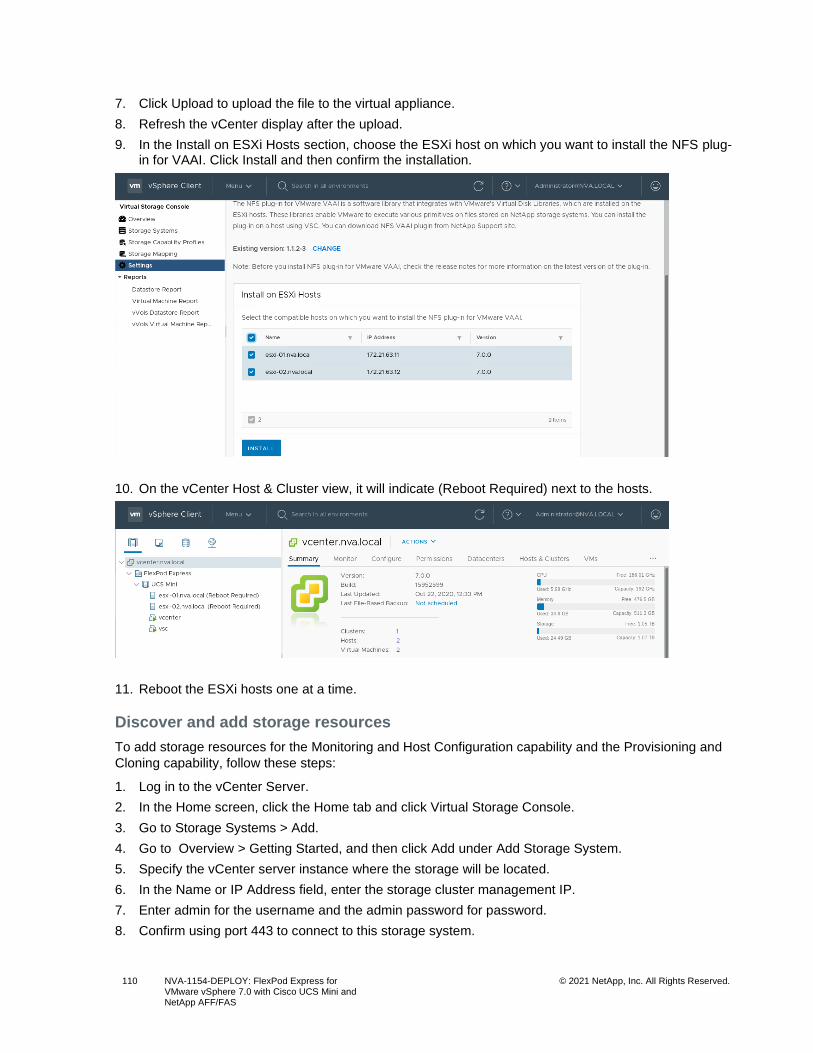
110 NVA-1154-DEPLOY: FlexPod Express for VMware vSphere 7.0 with Cisco UCS Mini and NetApp AFF/FAS
© 2021 NetApp, Inc. All Rights Reserved.
7. Click Upload to upload the file to the virtual appliance.
8. Refresh the vCenter display after the upload.
9. In the Install on ESXi Hosts section, choose the ESXi host on which you want to install the NFS plug-in for VAAI. Click Install and then confirm the installation.
10. On the vCenter Host & Cluster view, it will indicate (Reboot Required) next to the hosts.
11. Reboot the ESXi hosts one at a time.
Discover and add storage resources
To add storage resources for the Monitoring and Host Configuration capability and the Provisioning and
Cloning capability, follow these steps:
1. Log in to the vCenter Server.
2. In the Home screen, click the Home tab and click Virtual Storage Console.
3. Go to Storage Systems > Add.
4. Go to Overview > Getting Started, and then click Add under Add Storage System.
5. Specify the vCenter server instance where the storage will be located.
6. In the Name or IP Address field, enter the storage cluster management IP.
7. Enter admin for the username and the admin password for password.
8. Confirm using port 443 to connect to this storage system.
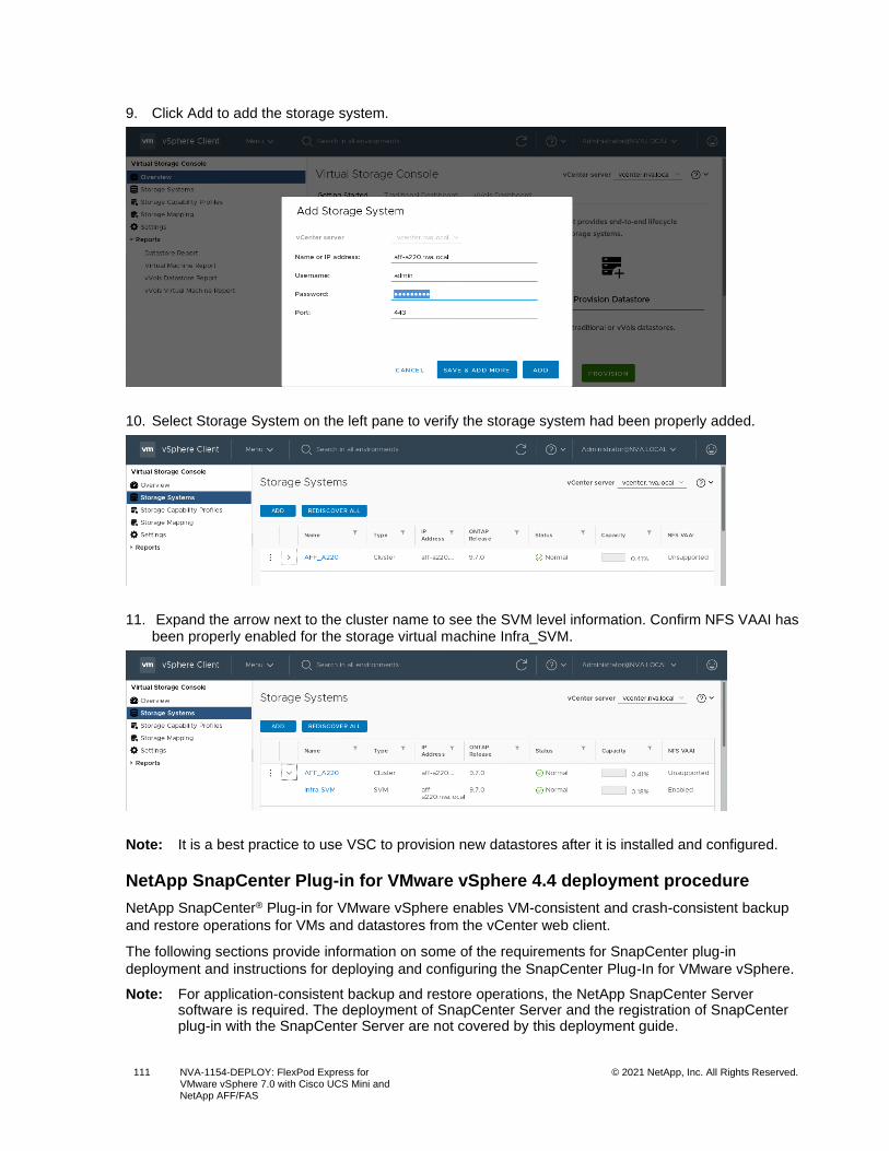
111 NVA-1154-DEPLOY: FlexPod Express for VMware vSphere 7.0 with Cisco UCS Mini and NetApp AFF/FAS
© 2021 NetApp, Inc. All Rights Reserved.
9. Click Add to add the storage system.
10. Select Storage System on the left pane to verify the storage system had been properly added.
11. Expand the arrow next to the cluster name to see the SVM level information. Confirm NFS VAAI has been properly enabled for the storage virtual machine Infra_SVM.
Note: It is a best practice to use VSC to provision new datastores after it is installed and configured.
NetApp SnapCenter Plug-in for VMware vSphere 4.4 deployment procedure
NetApp SnapCenter® Plug-in for VMware vSphere enables VM-consistent and crash-consistent backup
and restore operations for VMs and datastores from the vCenter web client.
The following sections provide information on some of the requirements for SnapCenter plug-in
deployment and instructions for deploying and configuring the SnapCenter Plug-In for VMware vSphere.
Note: For application-consistent backup and restore operations, the NetApp SnapCenter Server software is required. The deployment of SnapCenter Server and the registration of SnapCenter plug-in with the SnapCenter Server are not covered by this deployment guide.
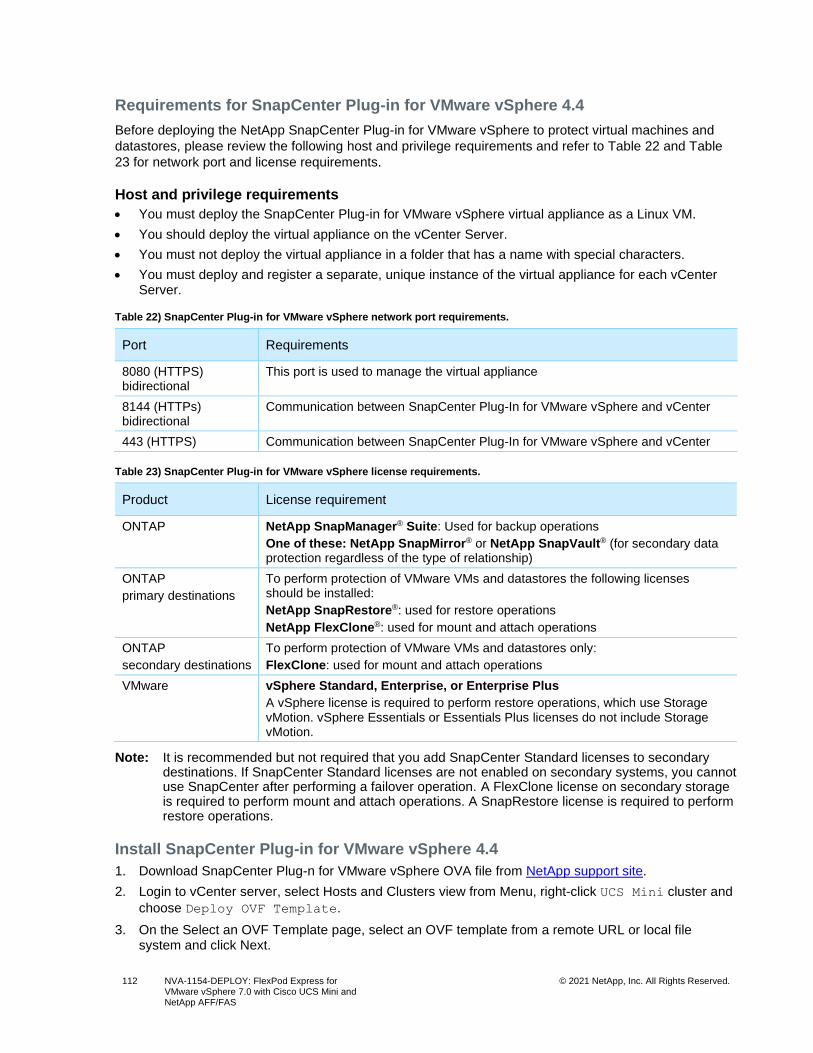
112 NVA-1154-DEPLOY: FlexPod Express for VMware vSphere 7.0 with Cisco UCS Mini and NetApp AFF/FAS
© 2021 NetApp, Inc. All Rights Reserved.
Requirements for SnapCenter Plug-in for VMware vSphere 4.4
Before deploying the NetApp SnapCenter Plug-in for VMware vSphere to protect virtual machines and
datastores, please review the following host and privilege requirements and refer to Table 22 and Table
23 for network port and license requirements.
Host and privilege requirements
• You must deploy the SnapCenter Plug-in for VMware vSphere virtual appliance as a Linux VM.
• You should deploy the virtual appliance on the vCenter Server.
• You must not deploy the virtual appliance in a folder that has a name with special characters.
• You must deploy and register a separate, unique instance of the virtual appliance for each vCenter Server.
Table 22) SnapCenter Plug-in for VMware vSphere network port requirements.
Port Requirements
8080 (HTTPS) bidirectional
This port is used to manage the virtual appliance
8144 (HTTPs) bidirectional
Communication between SnapCenter Plug-In for VMware vSphere and vCenter
443 (HTTPS) Communication between SnapCenter Plug-In for VMware vSphere and vCenter
Table 23) SnapCenter Plug-in for VMware vSphere license requirements.
Product License requirement
ONTAP NetApp SnapManager® Suite: Used for backup operations
One of these: NetApp SnapMirror® or NetApp SnapVault® (for secondary data protection regardless of the type of relationship)
ONTAP
primary destinations
To perform protection of VMware VMs and datastores the following licenses should be installed:
NetApp SnapRestore®: used for restore operations
NetApp FlexClone®: used for mount and attach operations
ONTAP
secondary destinations
To perform protection of VMware VMs and datastores only:
FlexClone: used for mount and attach operations
VMware vSphere Standard, Enterprise, or Enterprise Plus
A vSphere license is required to perform restore operations, which use Storage vMotion. vSphere Essentials or Essentials Plus licenses do not include Storage vMotion.
Note: It is recommended but not required that you add SnapCenter Standard licenses to secondary destinations. If SnapCenter Standard licenses are not enabled on secondary systems, you cannot use SnapCenter after performing a failover operation. A FlexClone license on secondary storage is required to perform mount and attach operations. A SnapRestore license is required to perform restore operations.
Install SnapCenter Plug-in for VMware vSphere 4.4
1. Download SnapCenter Plug-n for VMware vSphere OVA file from NetApp support site.
2. Login to vCenter server, select Hosts and Clusters view from Menu, right-click UCS Mini cluster and
choose Deploy OVF Template.
3. On the Select an OVF Template page, select an OVF template from a remote URL or local file system and click Next.
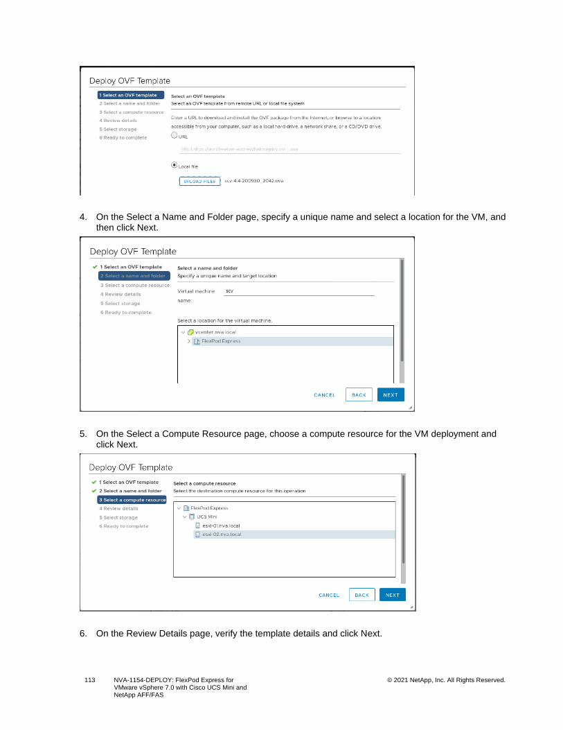
113 NVA-1154-DEPLOY: FlexPod Express for VMware vSphere 7.0 with Cisco UCS Mini and NetApp AFF/FAS
© 2021 NetApp, Inc. All Rights Reserved.
4. On the Select a Name and Folder page, specify a unique name and select a location for the VM, and then click Next.
5. On the Select a Compute Resource page, choose a compute resource for the VM deployment and click Next.
6. On the Review Details page, verify the template details and click Next.
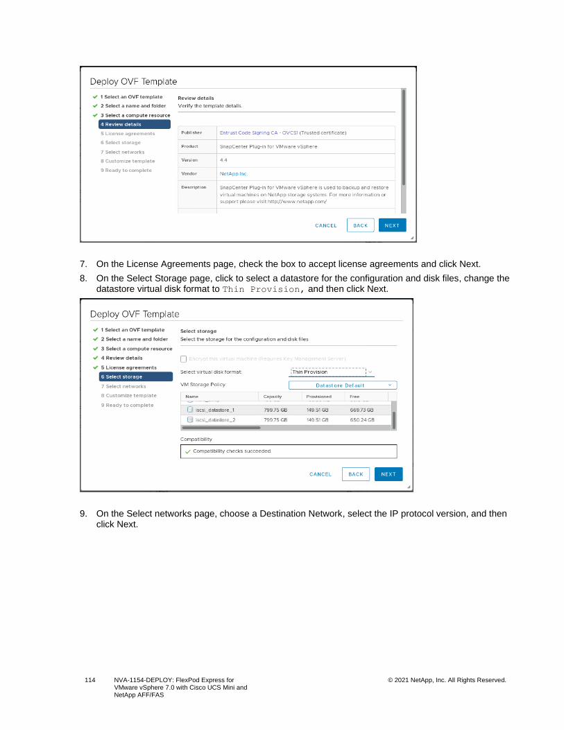
114 NVA-1154-DEPLOY: FlexPod Express for VMware vSphere 7.0 with Cisco UCS Mini and NetApp AFF/FAS
© 2021 NetApp, Inc. All Rights Reserved.
7. On the License Agreements page, check the box to accept license agreements and click Next.
8. On the Select Storage page, click to select a datastore for the configuration and disk files, change the datastore virtual disk format to Thin Provision, and then click Next.
9. On the Select networks page, choose a Destination Network, select the IP protocol version, and then click Next.
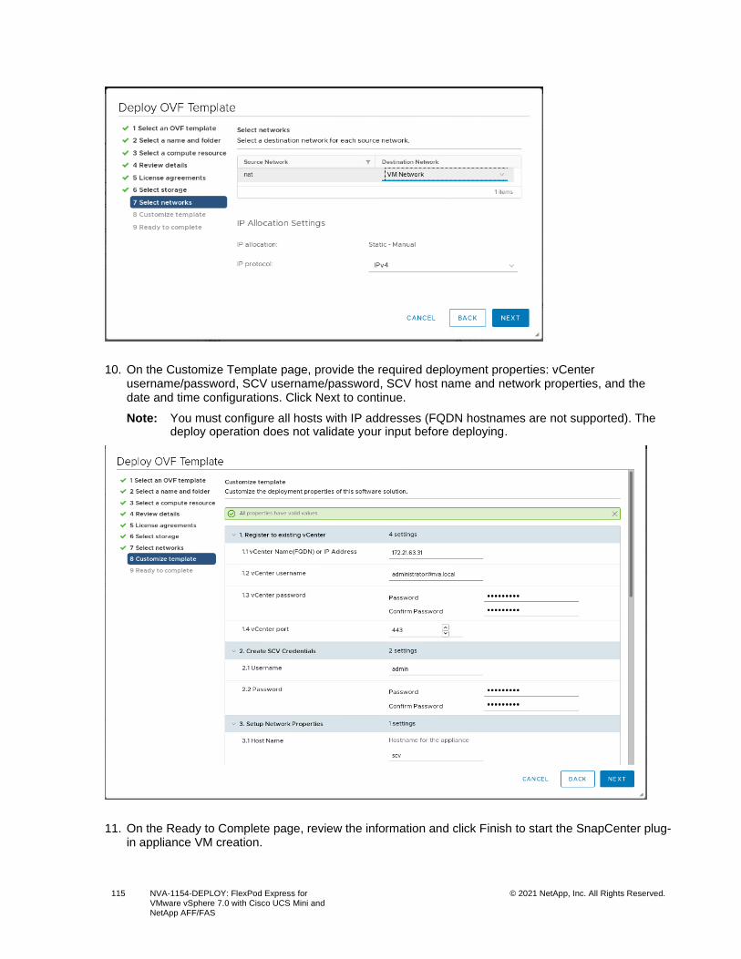
115 NVA-1154-DEPLOY: FlexPod Express for VMware vSphere 7.0 with Cisco UCS Mini and NetApp AFF/FAS
© 2021 NetApp, Inc. All Rights Reserved.
10. On the Customize Template page, provide the required deployment properties: vCenter username/password, SCV username/password, SCV host name and network properties, and the date and time configurations. Click Next to continue.
Note: You must configure all hosts with IP addresses (FQDN hostnames are not supported). The deploy operation does not validate your input before deploying.
11. On the Ready to Complete page, review the information and click Finish to start the SnapCenter plug-in appliance VM creation.
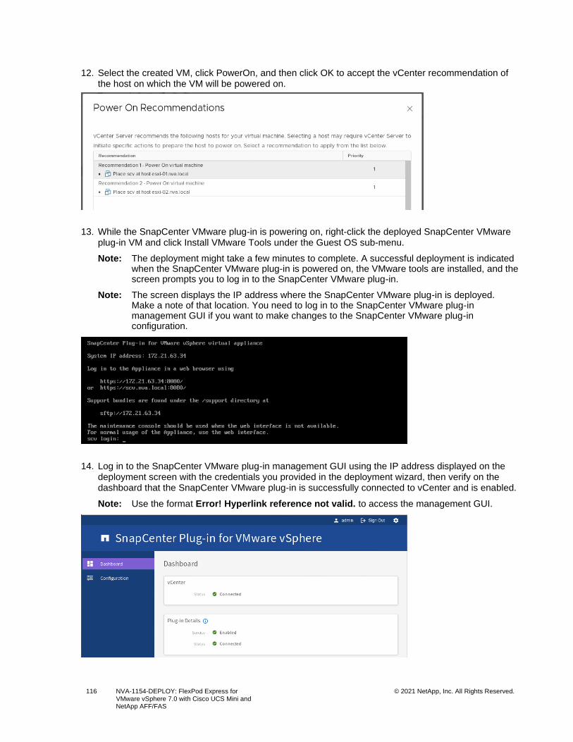
116 NVA-1154-DEPLOY: FlexPod Express for VMware vSphere 7.0 with Cisco UCS Mini and NetApp AFF/FAS
© 2021 NetApp, Inc. All Rights Reserved.
12. Select the created VM, click PowerOn, and then click OK to accept the vCenter recommendation of the host on which the VM will be powered on.
13. While the SnapCenter VMware plug-in is powering on, right-click the deployed SnapCenter VMware plug-in VM and click Install VMware Tools under the Guest OS sub-menu.
Note: The deployment might take a few minutes to complete. A successful deployment is indicated when the SnapCenter VMware plug-in is powered on, the VMware tools are installed, and the screen prompts you to log in to the SnapCenter VMware plug-in.
Note: The screen displays the IP address where the SnapCenter VMware plug-in is deployed. Make a note of that location. You need to log in to the SnapCenter VMware plug-in management GUI if you want to make changes to the SnapCenter VMware plug-in configuration.
14. Log in to the SnapCenter VMware plug-in management GUI using the IP address displayed on the deployment screen with the credentials you provided in the deployment wizard, then verify on the dashboard that the SnapCenter VMware plug-in is successfully connected to vCenter and is enabled.
Note: Use the format Error! Hyperlink reference not valid. to access the management GUI.
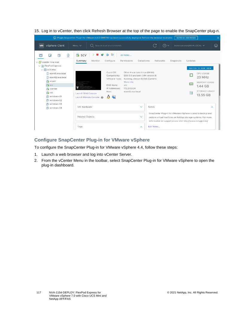
117 NVA-1154-DEPLOY: FlexPod Express for VMware vSphere 7.0 with Cisco UCS Mini and NetApp AFF/FAS
© 2021 NetApp, Inc. All Rights Reserved.
15. Log in to vCenter, then click Refresh Browser at the top of the page to enable the SnapCenter plug-n.
Configure SnapCenter Plug-in for VMware vSphere
To configure the SnapCenter Plug-in for VMware vSphere 4.4, follow these steps:
1. Launch a web browser and log into vCenter Server.
2. From the vCenter Menu in the toolbar, select SnapCenter Plug-in for VMware vSphere to open the plug-in dashboard.
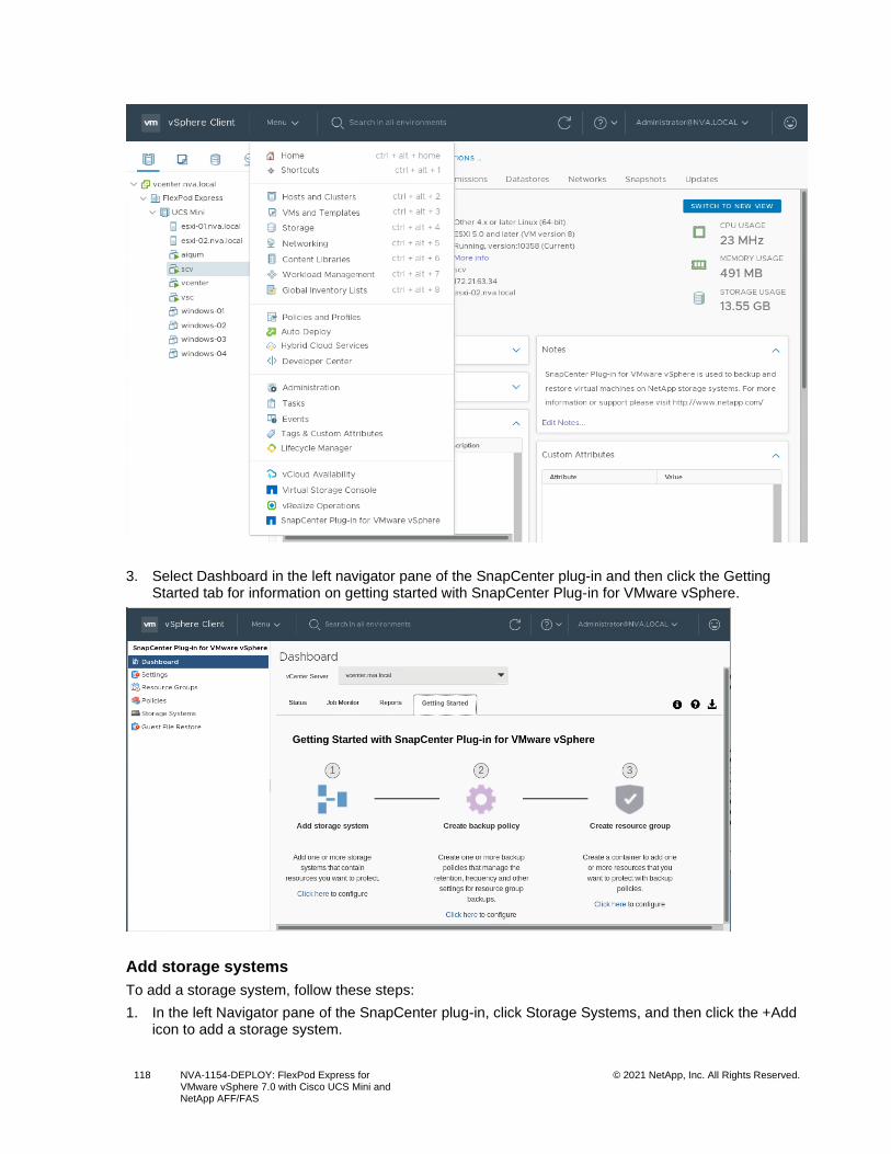
118 NVA-1154-DEPLOY: FlexPod Express for VMware vSphere 7.0 with Cisco UCS Mini and NetApp AFF/FAS
© 2021 NetApp, Inc. All Rights Reserved.
3. Select Dashboard in the left navigator pane of the SnapCenter plug-in and then click the Getting Started tab for information on getting started with SnapCenter Plug-in for VMware vSphere.
Add storage systems
To add a storage system, follow these steps:
1. In the left Navigator pane of the SnapCenter plug-in, click Storage Systems, and then click the +Add icon to add a storage system.
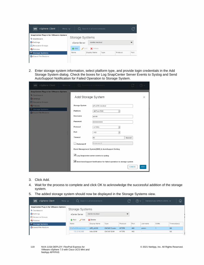
119 NVA-1154-DEPLOY: FlexPod Express for VMware vSphere 7.0 with Cisco UCS Mini and NetApp AFF/FAS
© 2021 NetApp, Inc. All Rights Reserved.
2. Enter storage system information, select platform type, and provide login credentials in the Add Storage System dialog. Check the boxes for Log SnapCenter Server Events to Syslog and Send AutoSupport Notification for Failed Operation to Storage System.
3. Click Add.
4. Wait for the process to complete and click OK to acknowledge the successful addition of the storage system.
5. The added storage system should now be displayed in the Storage Systems view.
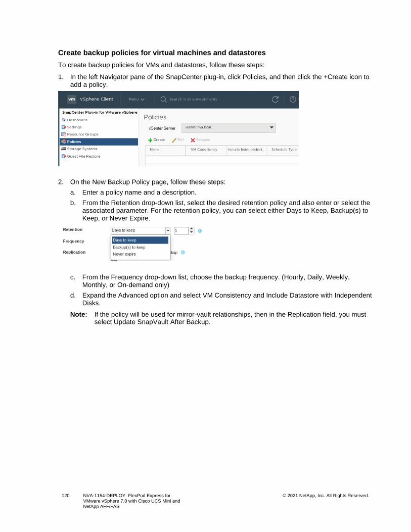
120 NVA-1154-DEPLOY: FlexPod Express for VMware vSphere 7.0 with Cisco UCS Mini and NetApp AFF/FAS
© 2021 NetApp, Inc. All Rights Reserved.
Create backup policies for virtual machines and datastores
To create backup policies for VMs and datastores, follow these steps:
1. In the left Navigator pane of the SnapCenter plug-in, click Policies, and then click the +Create icon to add a policy.
2. On the New Backup Policy page, follow these steps:
a. Enter a policy name and a description.
b. From the Retention drop-down list, select the desired retention policy and also enter or select the associated parameter. For the retention policy, you can select either Days to Keep, Backup(s) to Keep, or Never Expire.
c. From the Frequency drop-down list, choose the backup frequency. (Hourly, Daily, Weekly, Monthly, or On-demand only)
d. Expand the Advanced option and select VM Consistency and Include Datastore with Independent Disks.
Note: If the policy will be used for mirror-vault relationships, then in the Replication field, you must select Update SnapVault After Backup.
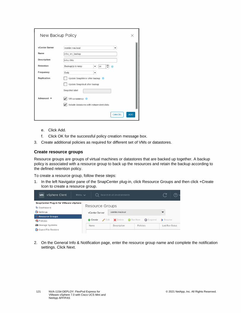
121 NVA-1154-DEPLOY: FlexPod Express for VMware vSphere 7.0 with Cisco UCS Mini and NetApp AFF/FAS
© 2021 NetApp, Inc. All Rights Reserved.
e. Click Add.
f. Click OK for the successful policy creation message box.
3. Create additional policies as required for different set of VMs or datastores.
Create resource groups
Resource groups are groups of virtual machines or datastores that are backed up together. A backup
policy is associated with a resource group to back up the resources and retain the backup according to
the defined retention policy.
To create a resource group, follow these steps:
1. In the left Navigator pane of the SnapCenter plug-in, click Resource Groups and then click +Create Icon to create a resource group.
2. On the General Info & Notification page, enter the resource group name and complete the notification settings. Click Next.
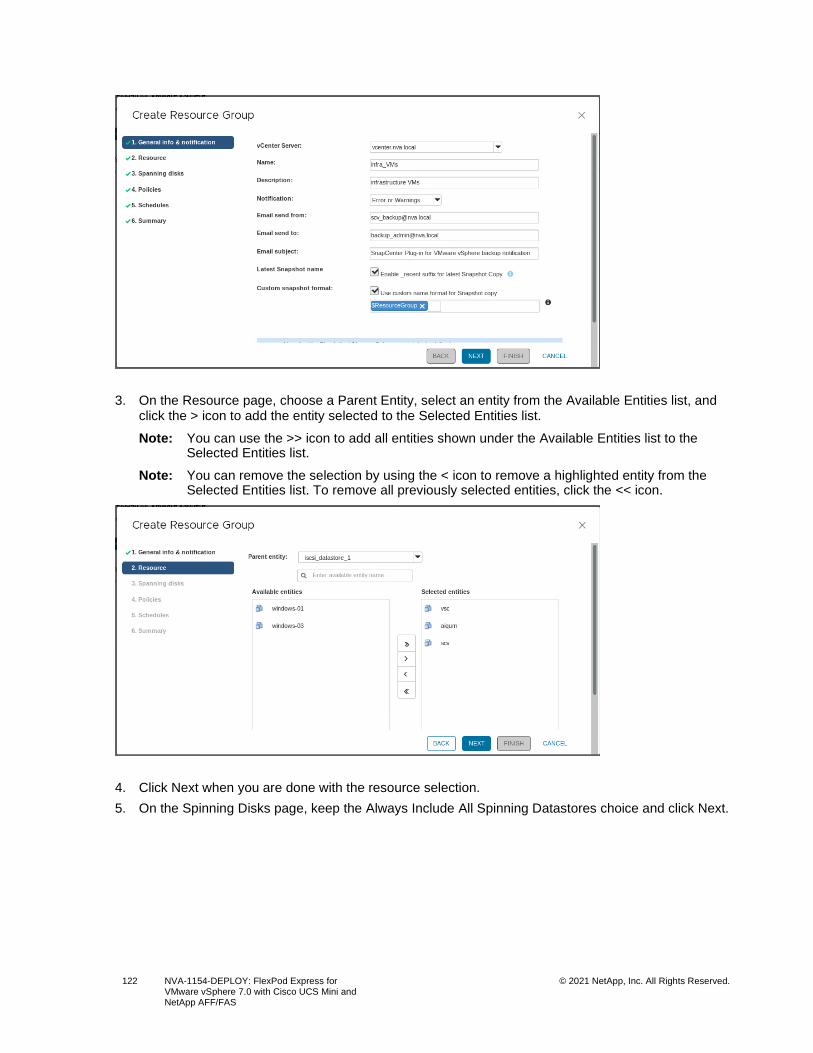
122 NVA-1154-DEPLOY: FlexPod Express for VMware vSphere 7.0 with Cisco UCS Mini and NetApp AFF/FAS
© 2021 NetApp, Inc. All Rights Reserved.
3. On the Resource page, choose a Parent Entity, select an entity from the Available Entities list, and click the > icon to add the entity selected to the Selected Entities list.
Note: You can use the >> icon to add all entities shown under the Available Entities list to the Selected Entities list.
Note: You can remove the selection by using the < icon to remove a highlighted entity from the Selected Entities list. To remove all previously selected entities, click the << icon.
4. Click Next when you are done with the resource selection.
5. On the Spinning Disks page, keep the Always Include All Spinning Datastores choice and click Next.
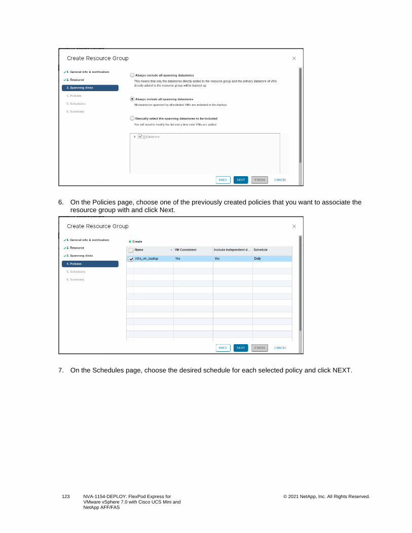
123 NVA-1154-DEPLOY: FlexPod Express for VMware vSphere 7.0 with Cisco UCS Mini and NetApp AFF/FAS
© 2021 NetApp, Inc. All Rights Reserved.
6. On the Policies page, choose one of the previously created policies that you want to associate the resource group with and click Next.
7. On the Schedules page, choose the desired schedule for each selected policy and click NEXT.
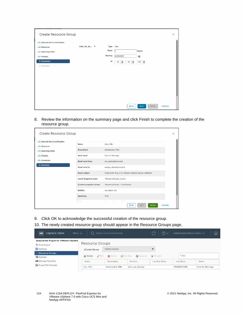
124 NVA-1154-DEPLOY: FlexPod Express for VMware vSphere 7.0 with Cisco UCS Mini and NetApp AFF/FAS
© 2021 NetApp, Inc. All Rights Reserved.
8. Review the information on the summary page and click Finish to complete the creation of the resource group.
9. Click OK to acknowledge the successful creation of the resource group.
10. The newly created resource group should appear in the Resource Groups page.
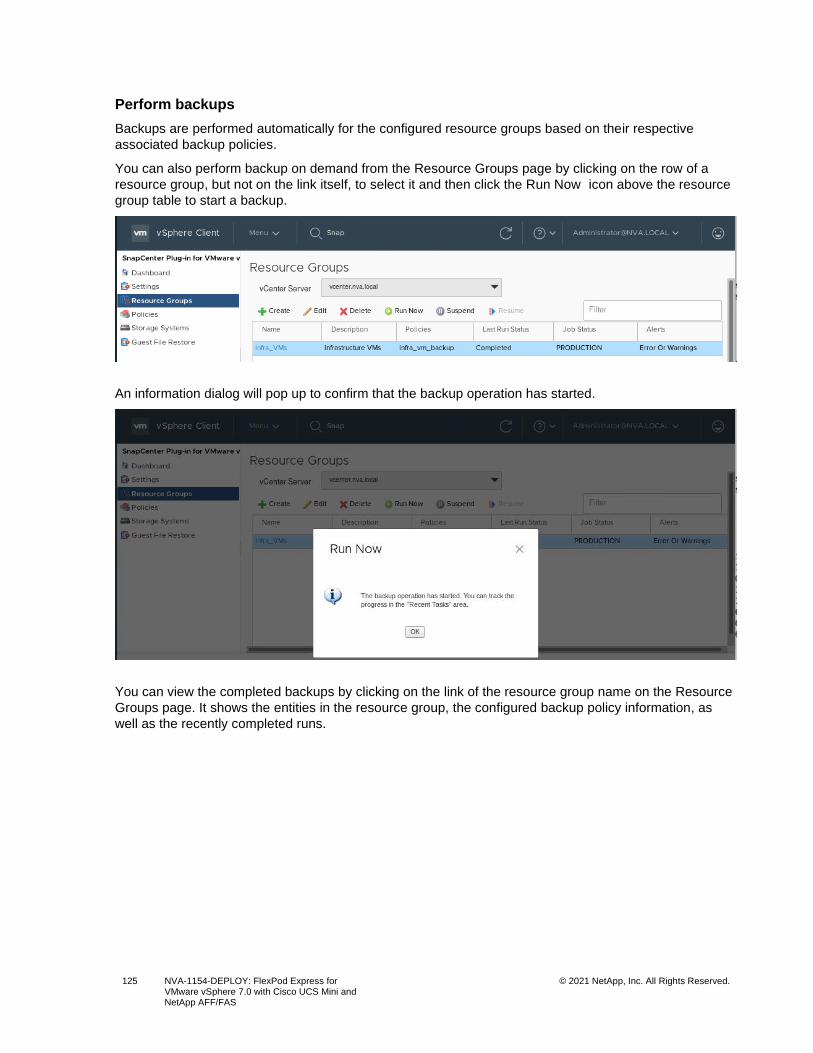
125 NVA-1154-DEPLOY: FlexPod Express for VMware vSphere 7.0 with Cisco UCS Mini and NetApp AFF/FAS
© 2021 NetApp, Inc. All Rights Reserved.
Perform backups
Backups are performed automatically for the configured resource groups based on their respective
associated backup policies.
You can also perform backup on demand from the Resource Groups page by clicking on the row of a
resource group, but not on the link itself, to select it and then click the Run Now icon above the resource
group table to start a backup.
An information dialog will pop up to confirm that the backup operation has started.
You can view the completed backups by clicking on the link of the resource group name on the Resource
Groups page. It shows the entities in the resource group, the configured backup policy information, as
well as the recently completed runs.
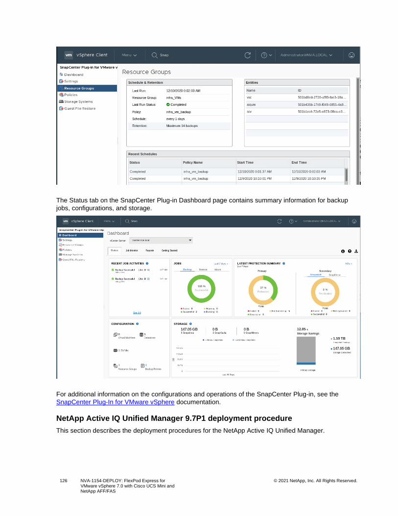
126 NVA-1154-DEPLOY: FlexPod Express for VMware vSphere 7.0 with Cisco UCS Mini and NetApp AFF/FAS
© 2021 NetApp, Inc. All Rights Reserved.
The Status tab on the SnapCenter Plug-in Dashboard page contains summary information for backup
jobs, configurations, and storage.
For additional information on the configurations and operations of the SnapCenter Plug-in, see the
SnapCenter Plug-In for VMware vSphere documentation.
NetApp Active IQ Unified Manager 9.7P1 deployment procedure
This section describes the deployment procedures for the NetApp Active IQ Unified Manager.
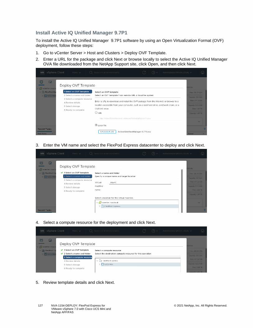
127 NVA-1154-DEPLOY: FlexPod Express for VMware vSphere 7.0 with Cisco UCS Mini and NetApp AFF/FAS
© 2021 NetApp, Inc. All Rights Reserved.
Install Active IQ Unified Manager 9.7P1
To install the Active IQ Unified Manager 9.7P1 software by using an Open Virtualization Format (OVF)
deployment, follow these steps:
1. Go to vCenter Server > Host and Clusters > Deploy OVF Template.
2. Enter a URL for the package and click Next or browse locally to select the Active IQ Unified Manager OVA file downloaded from the NetApp Support site, click Open, and then click Next.
3. Enter the VM name and select the FlexPod Express datacenter to deploy and click Next.
4. Select a compute resource for the deployment and click Next.
5. Review template details and click Next.
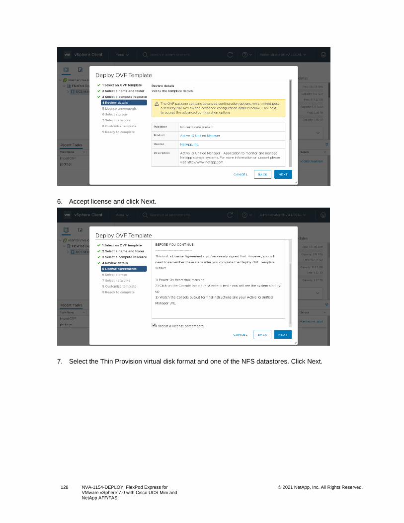
128 NVA-1154-DEPLOY: FlexPod Express for VMware vSphere 7.0 with Cisco UCS Mini and NetApp AFF/FAS
© 2021 NetApp, Inc. All Rights Reserved.
6. Accept license and click Next.
7. Select the Thin Provision virtual disk format and one of the NFS datastores. Click Next.
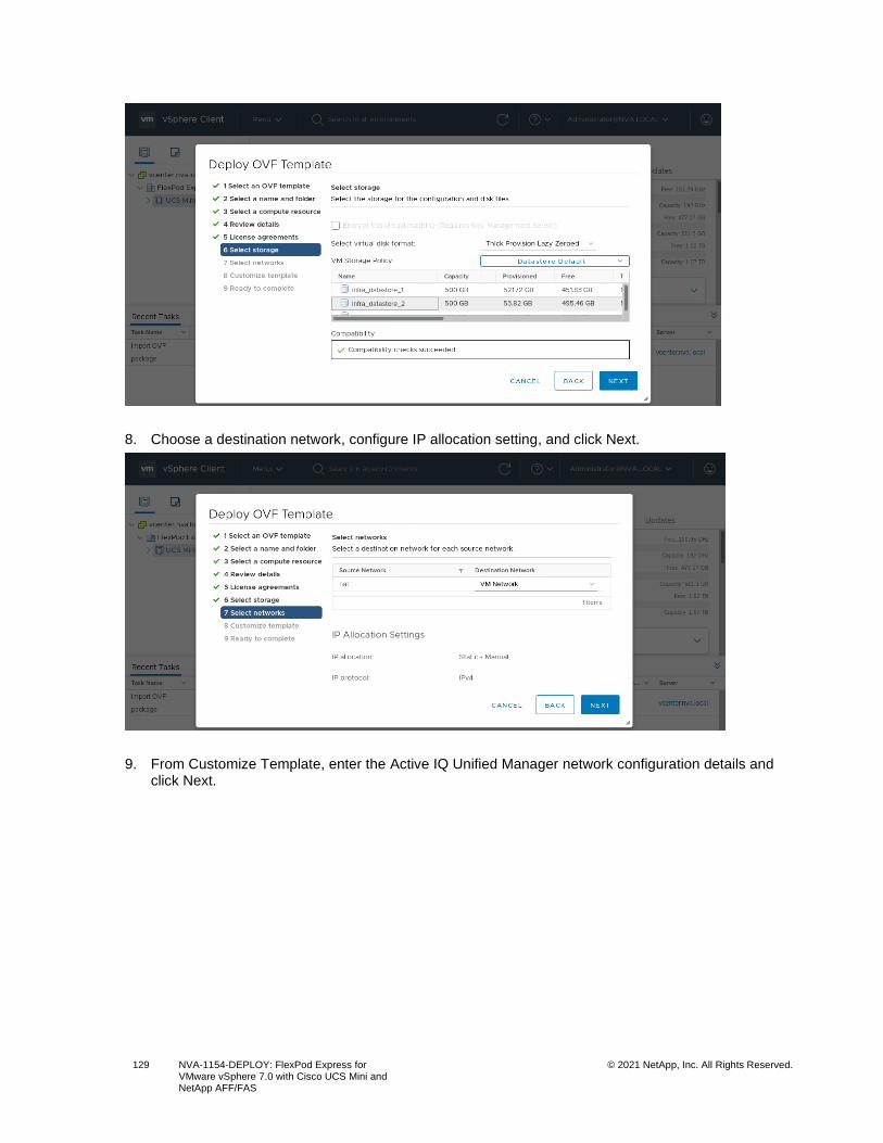
129 NVA-1154-DEPLOY: FlexPod Express for VMware vSphere 7.0 with Cisco UCS Mini and NetApp AFF/FAS
© 2021 NetApp, Inc. All Rights Reserved.
8. Choose a destination network, configure IP allocation setting, and click Next.
9. From Customize Template, enter the Active IQ Unified Manager network configuration details and click Next.
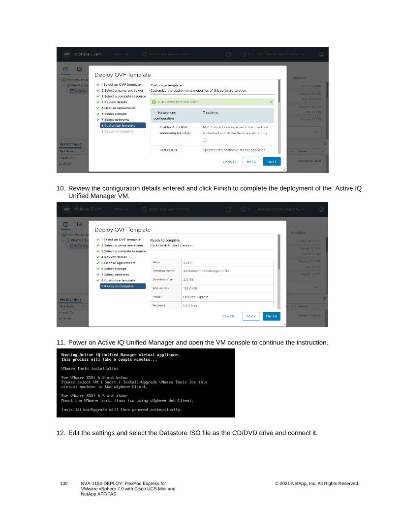
130 NVA-1154-DEPLOY: FlexPod Express for VMware vSphere 7.0 with Cisco UCS Mini and NetApp AFF/FAS
© 2021 NetApp, Inc. All Rights Reserved.
10. Review the configuration details entered and click Finish to complete the deployment of the Active IQ Unified Manager VM.
11. Power on Active IQ Unified Manager and open the VM console to continue the instruction.
12. Edit the settings and select the Datastore ISO file as the CD/DVD drive and connect it.
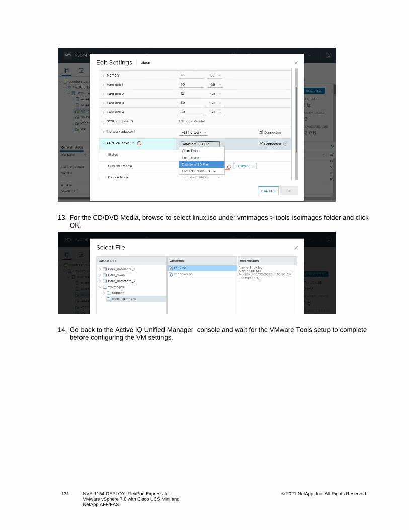
131 NVA-1154-DEPLOY: FlexPod Express for VMware vSphere 7.0 with Cisco UCS Mini and NetApp AFF/FAS
© 2021 NetApp, Inc. All Rights Reserved.
13. For the CD/DVD Media, browse to select linux.iso under vmimages > tools-isoimages folder and click OK.
14. Go back to the Active IQ Unified Manager console and wait for the VMware Tools setup to complete before configuring the VM settings.
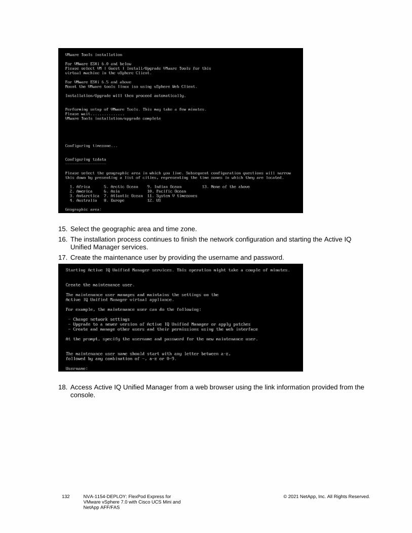
132 NVA-1154-DEPLOY: FlexPod Express for VMware vSphere 7.0 with Cisco UCS Mini and NetApp AFF/FAS
© 2021 NetApp, Inc. All Rights Reserved.
15. Select the geographic area and time zone.
16. The installation process continues to finish the network configuration and starting the Active IQ Unified Manager services.
17. Create the maintenance user by providing the username and password.
18. Access Active IQ Unified Manager from a web browser using the link information provided from the console.
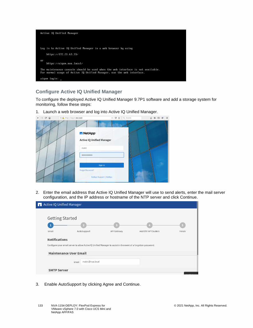
133 NVA-1154-DEPLOY: FlexPod Express for VMware vSphere 7.0 with Cisco UCS Mini and NetApp AFF/FAS
© 2021 NetApp, Inc. All Rights Reserved.
Configure Active IQ Unified Manager
To configure the deployed Active IQ Unified Manager 9.7P1 software and add a storage system for
monitoring, follow these steps:
1. Launch a web browser and log into Active IQ Unified Manager.
2. Enter the email address that Active IQ Unified Manager will use to send alerts, enter the mail server configuration, and the IP address or hostname of the NTP server and click Continue.
3. Enable AutoSupport by clicking Agree and Continue.
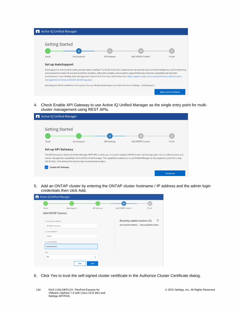
134 NVA-1154-DEPLOY: FlexPod Express for VMware vSphere 7.0 with Cisco UCS Mini and NetApp AFF/FAS
© 2021 NetApp, Inc. All Rights Reserved.
4. Check Enable API Gateway to use Active IQ Unified Manager as the single entry point for multi-cluster management using REST APIs.
5. Add an ONTAP cluster by entering the ONTAP cluster hostname / IP address and the admin login credentials then click Add.
6. Click Yes to trust the self-signed cluster certificate in the Authorize Cluster Certificate dialog.
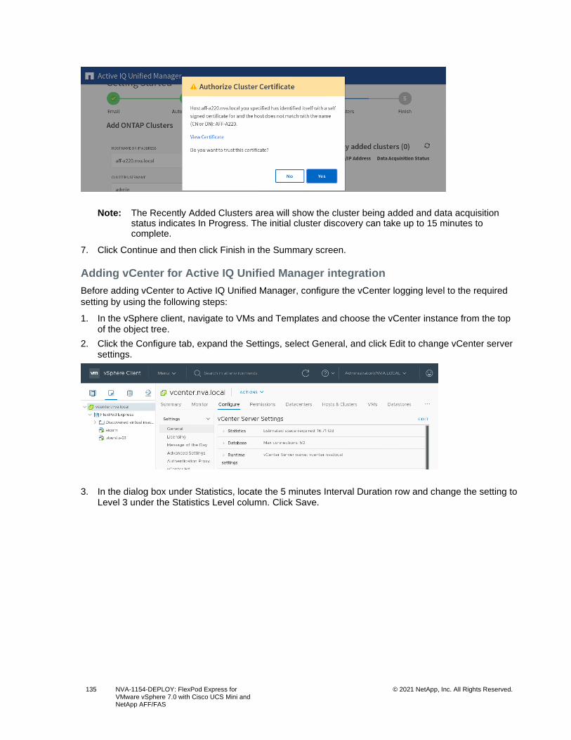
135 NVA-1154-DEPLOY: FlexPod Express for VMware vSphere 7.0 with Cisco UCS Mini and NetApp AFF/FAS
© 2021 NetApp, Inc. All Rights Reserved.
Note: The Recently Added Clusters area will show the cluster being added and data acquisition status indicates In Progress. The initial cluster discovery can take up to 15 minutes to complete.
7. Click Continue and then click Finish in the Summary screen.
Adding vCenter for Active IQ Unified Manager integration
Before adding vCenter to Active IQ Unified Manager, configure the vCenter logging level to the required
setting by using the following steps:
1. In the vSphere client, navigate to VMs and Templates and choose the vCenter instance from the top of the object tree.
2. Click the Configure tab, expand the Settings, select General, and click Edit to change vCenter server settings.
3. In the dialog box under Statistics, locate the 5 minutes Interval Duration row and change the setting to Level 3 under the Statistics Level column. Click Save.
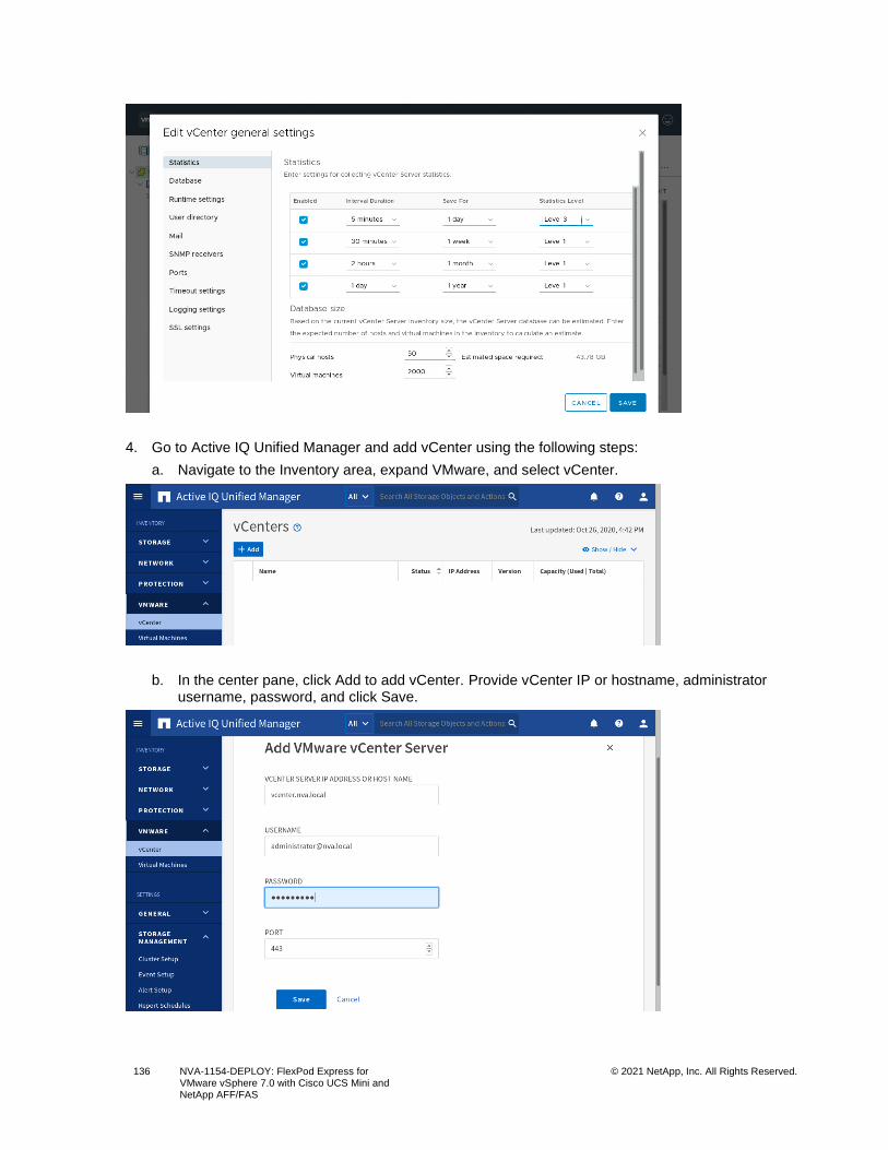
136 NVA-1154-DEPLOY: FlexPod Express for VMware vSphere 7.0 with Cisco UCS Mini and NetApp AFF/FAS
© 2021 NetApp, Inc. All Rights Reserved.
4. Go to Active IQ Unified Manager and add vCenter using the following steps:
a. Navigate to the Inventory area, expand VMware, and select vCenter.
b. In the center pane, click Add to add vCenter. Provide vCenter IP or hostname, administrator username, password, and click Save.
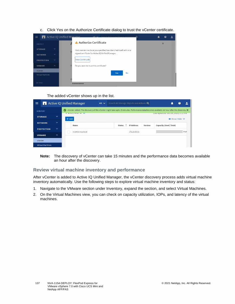
137 NVA-1154-DEPLOY: FlexPod Express for VMware vSphere 7.0 with Cisco UCS Mini and NetApp AFF/FAS
© 2021 NetApp, Inc. All Rights Reserved.
c. Click Yes on the Authorize Certificate dialog to trust the vCenter certificate.
The added vCenter shows up in the list.
Note: The discovery of vCenter can take 15 minutes and the performance data becomes available an hour after the discovery.
Review virtual machine inventory and performance
After vCenter is added to Active IQ Unified Manager, the vCenter discovery process adds virtual machine
inventory automatically. Use the following steps to explore virtual machine inventory and status:
1. Navigate to the VMware section under Inventory, expand the section, and select Virtual Machines.
2. On the Virtual Machines view, you can check on capacity utilization, IOPs, and latency of the virtual machines.
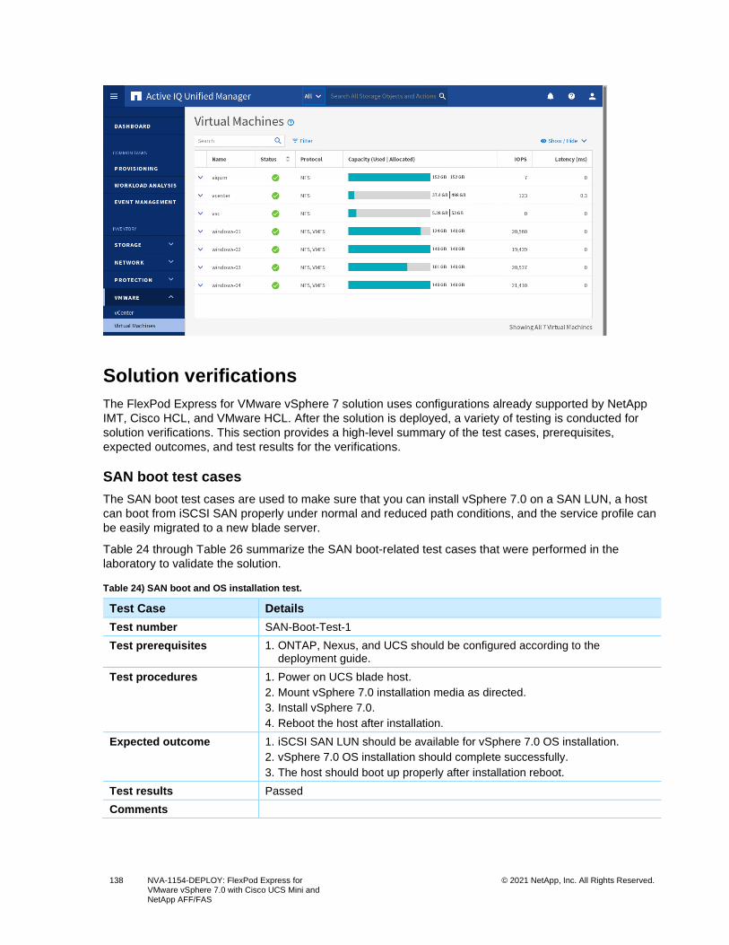
138 NVA-1154-DEPLOY: FlexPod Express for VMware vSphere 7.0 with Cisco UCS Mini and NetApp AFF/FAS
© 2021 NetApp, Inc. All Rights Reserved.
Solution verifications
The FlexPod Express for VMware vSphere 7 solution uses configurations already supported by NetApp
IMT, Cisco HCL, and VMware HCL. After the solution is deployed, a variety of testing is conducted for
solution verifications. This section provides a high-level summary of the test cases, prerequisites,
expected outcomes, and test results for the verifications.
SAN boot test cases
The SAN boot test cases are used to make sure that you can install vSphere 7.0 on a SAN LUN, a host
can boot from iSCSI SAN properly under normal and reduced path conditions, and the service profile can
be easily migrated to a new blade server.
Table 24 through Table 26 summarize the SAN boot-related test cases that were performed in the
laboratory to validate the solution.
Table 24) SAN boot and OS installation test.
Test Case Details
Test number SAN-Boot-Test-1
Test prerequisites 1. ONTAP, Nexus, and UCS should be configured according to the deployment guide.
Test procedures 1. Power on UCS blade host.
2. Mount vSphere 7.0 installation media as directed.
3. Install vSphere 7.0.
4. Reboot the host after installation.
Expected outcome 1. iSCSI SAN LUN should be available for vSphere 7.0 OS installation.
2. vSphere 7.0 OS installation should complete successfully.
3. The host should boot up properly after installation reboot.
Test results Passed
Comments
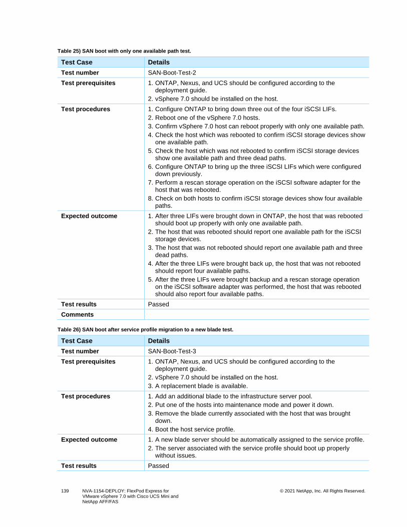
139 NVA-1154-DEPLOY: FlexPod Express for VMware vSphere 7.0 with Cisco UCS Mini and NetApp AFF/FAS
© 2021 NetApp, Inc. All Rights Reserved.
Table 25) SAN boot with only one available path test.
Test Case Details
Test number SAN-Boot-Test-2
Test prerequisites 1. ONTAP, Nexus, and UCS should be configured according to the deployment guide.
2. vSphere 7.0 should be installed on the host.
Test procedures 1. Configure ONTAP to bring down three out of the four iSCSI LIFs.
2. Reboot one of the vSphere 7.0 hosts.
3. Confirm vSphere 7.0 host can reboot properly with only one available path.
4. Check the host which was rebooted to confirm iSCSI storage devices show one available path.
5. Check the host which was not rebooted to confirm iSCSI storage devices show one available path and three dead paths.
6. Configure ONTAP to bring up the three iSCSI LIFs which were configured down previously.
7. Perform a rescan storage operation on the iSCSI software adapter for the host that was rebooted.
8. Check on both hosts to confirm iSCSI storage devices show four available paths.
Expected outcome 1. After three LIFs were brought down in ONTAP, the host that was rebooted should boot up properly with only one available path.
2. The host that was rebooted should report one available path for the iSCSI storage devices.
3. The host that was not rebooted should report one available path and three dead paths.
4. After the three LIFs were brought back up, the host that was not rebooted should report four available paths.
5. After the three LIFs were brought backup and a rescan storage operation on the iSCSI software adapter was performed, the host that was rebooted should also report four available paths.
Test results Passed
Comments
Table 26) SAN boot after service profile migration to a new blade test.
Test Case Details
Test number SAN-Boot-Test-3
Test prerequisites 1. ONTAP, Nexus, and UCS should be configured according to the deployment guide.
2. vSphere 7.0 should be installed on the host.
3. A replacement blade is available.
Test procedures 1. Add an additional blade to the infrastructure server pool.
2. Put one of the hosts into maintenance mode and power it down.
3. Remove the blade currently associated with the host that was brought down.
4. Boot the host service profile.
Expected outcome 1. A new blade server should be automatically assigned to the service profile.
2. The server associated with the service profile should boot up properly without issues.
Test results Passed
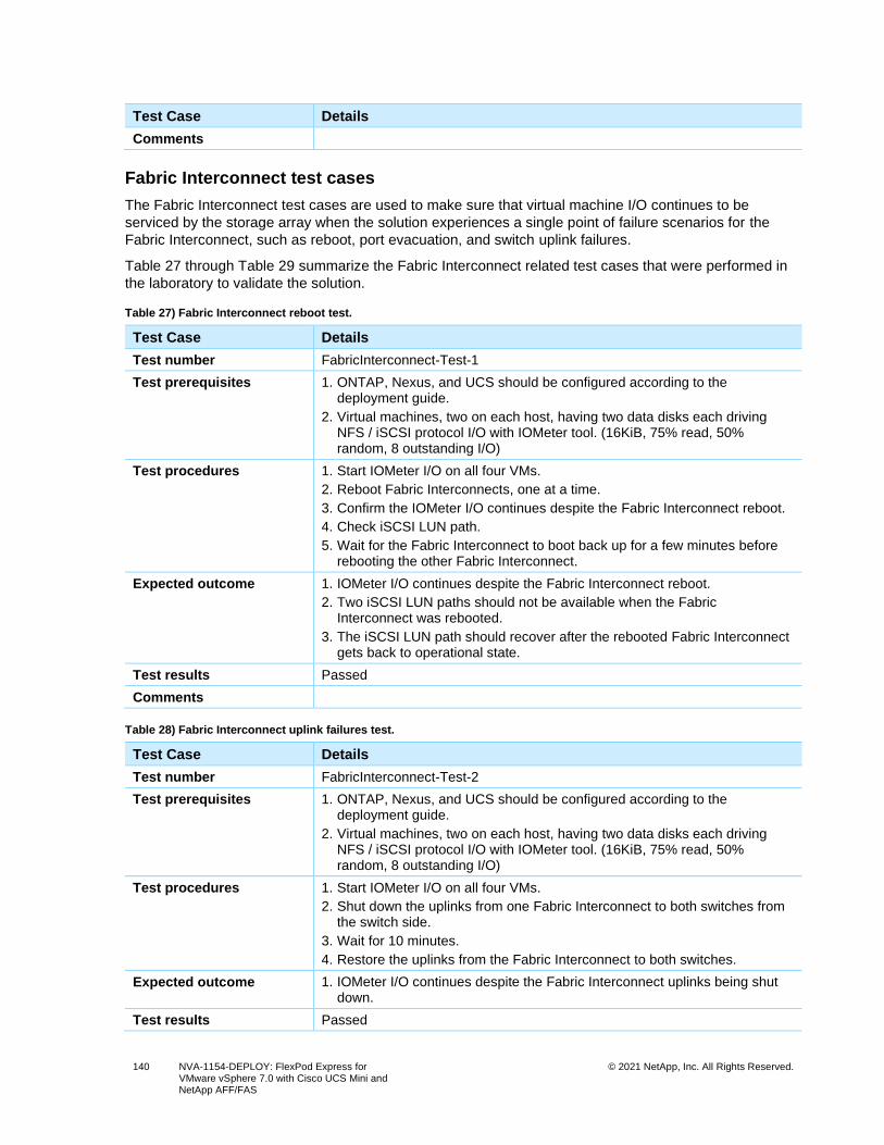
140 NVA-1154-DEPLOY: FlexPod Express for VMware vSphere 7.0 with Cisco UCS Mini and NetApp AFF/FAS
© 2021 NetApp, Inc. All Rights Reserved.
Test Case Details
Comments
Fabric Interconnect test cases
The Fabric Interconnect test cases are used to make sure that virtual machine I/O continues to be
serviced by the storage array when the solution experiences a single point of failure scenarios for the
Fabric Interconnect, such as reboot, port evacuation, and switch uplink failures.
Table 27 through Table 29 summarize the Fabric Interconnect related test cases that were performed in
the laboratory to validate the solution.
Table 27) Fabric Interconnect reboot test.
Test Case Details
Test number FabricInterconnect-Test-1
Test prerequisites 1. ONTAP, Nexus, and UCS should be configured according to the deployment guide.
2. Virtual machines, two on each host, having two data disks each driving NFS / iSCSI protocol I/O with IOMeter tool. (16KiB, 75% read, 50% random, 8 outstanding I/O)
Test procedures 1. Start IOMeter I/O on all four VMs.
2. Reboot Fabric Interconnects, one at a time.
3. Confirm the IOMeter I/O continues despite the Fabric Interconnect reboot.
4. Check iSCSI LUN path.
5. Wait for the Fabric Interconnect to boot back up for a few minutes before rebooting the other Fabric Interconnect.
Expected outcome 1. IOMeter I/O continues despite the Fabric Interconnect reboot.
2. Two iSCSI LUN paths should not be available when the Fabric Interconnect was rebooted.
3. The iSCSI LUN path should recover after the rebooted Fabric Interconnect gets back to operational state.
Test results Passed
Comments
Table 28) Fabric Interconnect uplink failures test.
Test Case Details
Test number FabricInterconnect-Test-2
Test prerequisites 1. ONTAP, Nexus, and UCS should be configured according to the deployment guide.
2. Virtual machines, two on each host, having two data disks each driving NFS / iSCSI protocol I/O with IOMeter tool. (16KiB, 75% read, 50% random, 8 outstanding I/O)
Test procedures 1. Start IOMeter I/O on all four VMs.
2. Shut down the uplinks from one Fabric Interconnect to both switches from the switch side.
3. Wait for 10 minutes.
4. Restore the uplinks from the Fabric Interconnect to both switches.
Expected outcome 1. IOMeter I/O continues despite the Fabric Interconnect uplinks being shut down.
Test results Passed
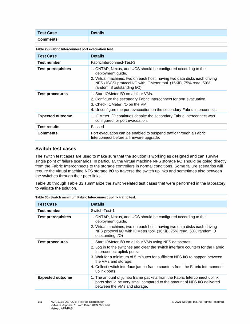
141 NVA-1154-DEPLOY: FlexPod Express for VMware vSphere 7.0 with Cisco UCS Mini and NetApp AFF/FAS
© 2021 NetApp, Inc. All Rights Reserved.
Test Case Details
Comments
Table 29) Fabric Interconnect port evacuation test.
Test Case Details
Test number FabricInterconnect-Test-3
Test prerequisites 1. ONTAP, Nexus, and UCS should be configured according to the deployment guide.
2. Virtual machines, two on each host, having two data disks each driving NFS / iSCSI protocol I/O with IOMeter tool. (16KiB, 75% read, 50% random, 8 outstanding I/O)
Test procedures 1. Start IOMeter I/O on all four VMs.
2. Configure the secondary Fabric Interconnect for port evacuation.
3. Check IOMeter I/O on the VM.
4. Unconfigure the port evacuation on the secondary Fabric Interconnect.
Expected outcome 1. IOMeter I/O continues despite the secondary Fabric Interconnect was configured for port evacuation.
Test results Passed
Comments Port evacuation can be enabled to suspend traffic through a Fabric Interconnect before a firmware upgrade.
Switch test cases
The switch test cases are used to make sure that the solution is working as designed and can survive
single point of failure scenarios. In particular, the virtual machine NFS storage I/O should be going directly
from the Fabric Interconnects to the storage controllers in normal conditions. Some failure scenarios will
require the virtual machine NFS storage I/O to traverse the switch uplinks and sometimes also between
the switches through their peer links.
Table 30 through Table 33 summarize the switch-related test cases that were performed in the laboratory
to validate the solution.
Table 30) Switch minimum Fabric Interconnect uplink traffic test.
Test Case Details
Test number Switch-Test-1
Test prerequisites 1. ONTAP, Nexus, and UCS should be configured according to the deployment guide.
2. Virtual machines, two on each host, having two data disks each driving NFS protocol I/O with IOMeter tool. (16KiB, 75% read, 50% random, 8 outstanding I/O)
Test procedures 1. Start IOMeter I/O on all four VMs using NFS datastores.
2. Log in to the switches and clear the switch interface counters for the Fabric Interconnect uplink ports.
3. Wait for a minimum of 5 minutes for sufficient NFS I/O to happen between the VMs and storage.
4. Collect switch interface jumbo frame counters from the Fabric Interconnect uplink ports.
Expected outcome 1. The amount of jumbo frame packets from the Fabric Interconnect uplink ports should be very small compared to the amount of NFS I/O delivered between the VMs and storage.
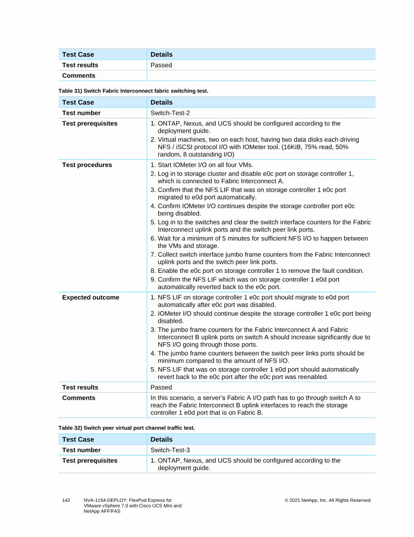
142 NVA-1154-DEPLOY: FlexPod Express for VMware vSphere 7.0 with Cisco UCS Mini and NetApp AFF/FAS
© 2021 NetApp, Inc. All Rights Reserved.
Test Case Details
Test results Passed
Comments
Table 31) Switch Fabric Interconnect fabric switching test.
Test Case Details
Test number Switch-Test-2
Test prerequisites 1. ONTAP, Nexus, and UCS should be configured according to the deployment guide.
2. Virtual machines, two on each host, having two data disks each driving NFS / iSCSI protocol I/O with IOMeter tool. (16KiB, 75% read, 50% random, 8 outstanding I/O)
Test procedures 1. Start IOMeter I/O on all four VMs.
2. Log in to storage cluster and disable e0c port on storage controller 1, which is connected to Fabric Interconnect A.
3. Confirm that the NFS LIF that was on storage controller 1 e0c port migrated to e0d port automatically.
4. Confirm IOMeter I/O continues despite the storage controller port e0c being disabled.
5. Log in to the switches and clear the switch interface counters for the Fabric Interconnect uplink ports and the switch peer link ports.
6. Wait for a minimum of 5 minutes for sufficient NFS I/O to happen between the VMs and storage.
7. Collect switch interface jumbo frame counters from the Fabric Interconnect uplink ports and the switch peer link ports.
8. Enable the e0c port on storage controller 1 to remove the fault condition.
9. Confirm the NFS LIF which was on storage controller 1 e0d port automatically reverted back to the e0c port.
Expected outcome 1. NFS LIF on storage controller 1 e0c port should migrate to e0d port automatically after e0c port was disabled.
2. IOMeter I/O should continue despite the storage controller 1 e0c port being disabled.
3. The jumbo frame counters for the Fabric Interconnect A and Fabric Interconnect B uplink ports on switch A should increase significantly due to NFS I/O going through those ports.
4. The jumbo frame counters between the switch peer links ports should be minimum compared to the amount of NFS I/O.
5. NFS LIF that was on storage controller 1 e0d port should automatically revert back to the e0c port after the e0c port was reenabled.
Test results Passed
Comments In this scenario, a server’s Fabric A I/O path has to go through switch A to reach the Fabric Interconnect B uplink interfaces to reach the storage controller 1 e0d port that is on Fabric B.
Table 32) Switch peer virtual port channel traffic test.
Test Case Details
Test number Switch-Test-3
Test prerequisites 1. ONTAP, Nexus, and UCS should be configured according to the deployment guide.
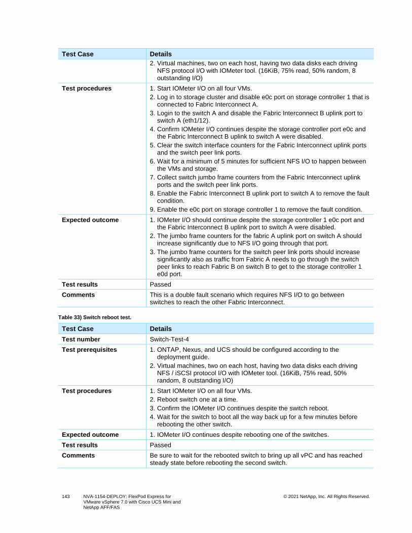
143 NVA-1154-DEPLOY: FlexPod Express for VMware vSphere 7.0 with Cisco UCS Mini and NetApp AFF/FAS
© 2021 NetApp, Inc. All Rights Reserved.
Test Case Details
2. Virtual machines, two on each host, having two data disks each driving NFS protocol I/O with IOMeter tool. (16KiB, 75% read, 50% random, 8 outstanding I/O)
Test procedures 1. Start IOMeter I/O on all four VMs.
2. Log in to storage cluster and disable e0c port on storage controller 1 that is connected to Fabric Interconnect A.
3. Login to the switch A and disable the Fabric Interconnect B uplink port to switch A (eth1/12).
4. Confirm IOMeter I/O continues despite the storage controller port e0c and the Fabric Interconnect B uplink to switch A were disabled.
5. Clear the switch interface counters for the Fabric Interconnect uplink ports and the switch peer link ports.
6. Wait for a minimum of 5 minutes for sufficient NFS I/O to happen between the VMs and storage.
7. Collect switch jumbo frame counters from the Fabric Interconnect uplink ports and the switch peer link ports.
8. Enable the Fabric Interconnect B uplink port to switch A to remove the fault condition.
9. Enable the e0c port on storage controller 1 to remove the fault condition.
Expected outcome 1. IOMeter I/O should continue despite the storage controller 1 e0c port and the Fabric Interconnect B uplink port to switch A were disabled.
2. The jumbo frame counters for the fabric A uplink port on switch A should increase significantly due to NFS I/O going through that port.
3. The jumbo frame counters for the switch peer link ports should increase significantly also as traffic from Fabric A needs to go through the switch peer links to reach Fabric B on switch B to get to the storage controller 1 e0d port.
Test results Passed
Comments This is a double fault scenario which requires NFS I/O to go between switches to reach the other Fabric Interconnect.
Table 33) Switch reboot test.
Test Case Details
Test number Switch-Test-4
Test prerequisites 1. ONTAP, Nexus, and UCS should be configured according to the deployment guide.
2. Virtual machines, two on each host, having two data disks each driving NFS / iSCSI protocol I/O with IOMeter tool. (16KiB, 75% read, 50% random, 8 outstanding I/O)
Test procedures 1. Start IOMeter I/O on all four VMs.
2. Reboot switch one at a time.
3. Confirm the IOMeter I/O continues despite the switch reboot.
4. Wait for the switch to boot all the way back up for a few minutes before rebooting the other switch.
Expected outcome 1. IOMeter I/O continues despite rebooting one of the switches.
Test results Passed
Comments Be sure to wait for the rebooted switch to bring up all vPC and has reached steady state before rebooting the second switch.
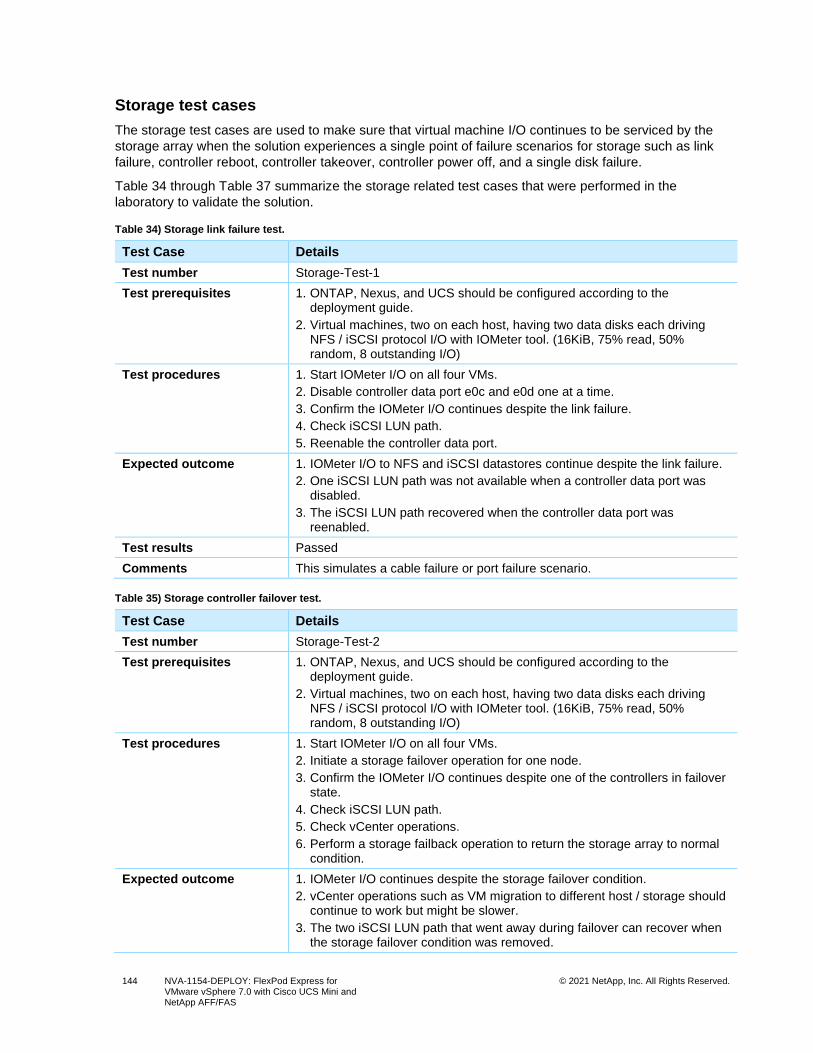
144 NVA-1154-DEPLOY: FlexPod Express for VMware vSphere 7.0 with Cisco UCS Mini and NetApp AFF/FAS
© 2021 NetApp, Inc. All Rights Reserved.
Storage test cases
The storage test cases are used to make sure that virtual machine I/O continues to be serviced by the
storage array when the solution experiences a single point of failure scenarios for storage such as link
failure, controller reboot, controller takeover, controller power off, and a single disk failure.
Table 34 through Table 37 summarize the storage related test cases that were performed in the
laboratory to validate the solution.
Table 34) Storage link failure test.
Test Case Details
Test number Storage-Test-1
Test prerequisites 1. ONTAP, Nexus, and UCS should be configured according to the deployment guide.
2. Virtual machines, two on each host, having two data disks each driving NFS / iSCSI protocol I/O with IOMeter tool. (16KiB, 75% read, 50% random, 8 outstanding I/O)
Test procedures 1. Start IOMeter I/O on all four VMs.
2. Disable controller data port e0c and e0d one at a time.
3. Confirm the IOMeter I/O continues despite the link failure.
4. Check iSCSI LUN path.
5. Reenable the controller data port.
Expected outcome 1. IOMeter I/O to NFS and iSCSI datastores continue despite the link failure.
2. One iSCSI LUN path was not available when a controller data port was disabled.
3. The iSCSI LUN path recovered when the controller data port was reenabled.
Test results Passed
Comments This simulates a cable failure or port failure scenario.
Table 35) Storage controller failover test.
Test Case Details
Test number Storage-Test-2
Test prerequisites 1. ONTAP, Nexus, and UCS should be configured according to the deployment guide.
2. Virtual machines, two on each host, having two data disks each driving NFS / iSCSI protocol I/O with IOMeter tool. (16KiB, 75% read, 50% random, 8 outstanding I/O)
Test procedures 1. Start IOMeter I/O on all four VMs.
2. Initiate a storage failover operation for one node.
3. Confirm the IOMeter I/O continues despite one of the controllers in failover state.
4. Check iSCSI LUN path.
5. Check vCenter operations.
6. Perform a storage failback operation to return the storage array to normal condition.
Expected outcome 1. IOMeter I/O continues despite the storage failover condition.
2. vCenter operations such as VM migration to different host / storage should continue to work but might be slower.
3. The two iSCSI LUN path that went away during failover can recover when the storage failover condition was removed.
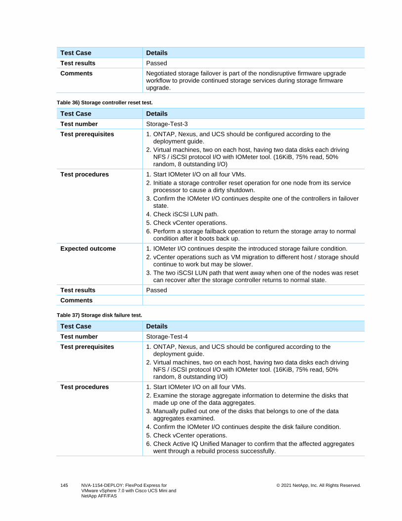
145 NVA-1154-DEPLOY: FlexPod Express for VMware vSphere 7.0 with Cisco UCS Mini and NetApp AFF/FAS
© 2021 NetApp, Inc. All Rights Reserved.
Test Case Details
Test results Passed
Comments Negotiated storage failover is part of the nondisruptive firmware upgrade workflow to provide continued storage services during storage firmware upgrade.
Table 36) Storage controller reset test.
Test Case Details
Test number Storage-Test-3
Test prerequisites 1. ONTAP, Nexus, and UCS should be configured according to the deployment guide.
2. Virtual machines, two on each host, having two data disks each driving NFS / iSCSI protocol I/O with IOMeter tool. (16KiB, 75% read, 50% random, 8 outstanding I/O)
Test procedures 1. Start IOMeter I/O on all four VMs.
2. Initiate a storage controller reset operation for one node from its service processor to cause a dirty shutdown.
3. Confirm the IOMeter I/O continues despite one of the controllers in failover state.
4. Check iSCSI LUN path.
5. Check vCenter operations.
6. Perform a storage failback operation to return the storage array to normal condition after it boots back up.
Expected outcome 1. IOMeter I/O continues despite the introduced storage failure condition.
2. vCenter operations such as VM migration to different host / storage should continue to work but may be slower.
3. The two iSCSI LUN path that went away when one of the nodes was reset can recover after the storage controller returns to normal state.
Test results Passed
Comments
Table 37) Storage disk failure test.
Test Case Details
Test number Storage-Test-4
Test prerequisites 1. ONTAP, Nexus, and UCS should be configured according to the deployment guide.
2. Virtual machines, two on each host, having two data disks each driving NFS / iSCSI protocol I/O with IOMeter tool. (16KiB, 75% read, 50% random, 8 outstanding I/O)
Test procedures 1. Start IOMeter I/O on all four VMs.
2. Examine the storage aggregate information to determine the disks that made up one of the data aggregates.
3. Manually pulled out one of the disks that belongs to one of the data aggregates examined.
4. Confirm the IOMeter I/O continues despite the disk failure condition.
5. Check vCenter operations.
6. Check Active IQ Unified Manager to confirm that the affected aggregates went through a rebuild process successfully.
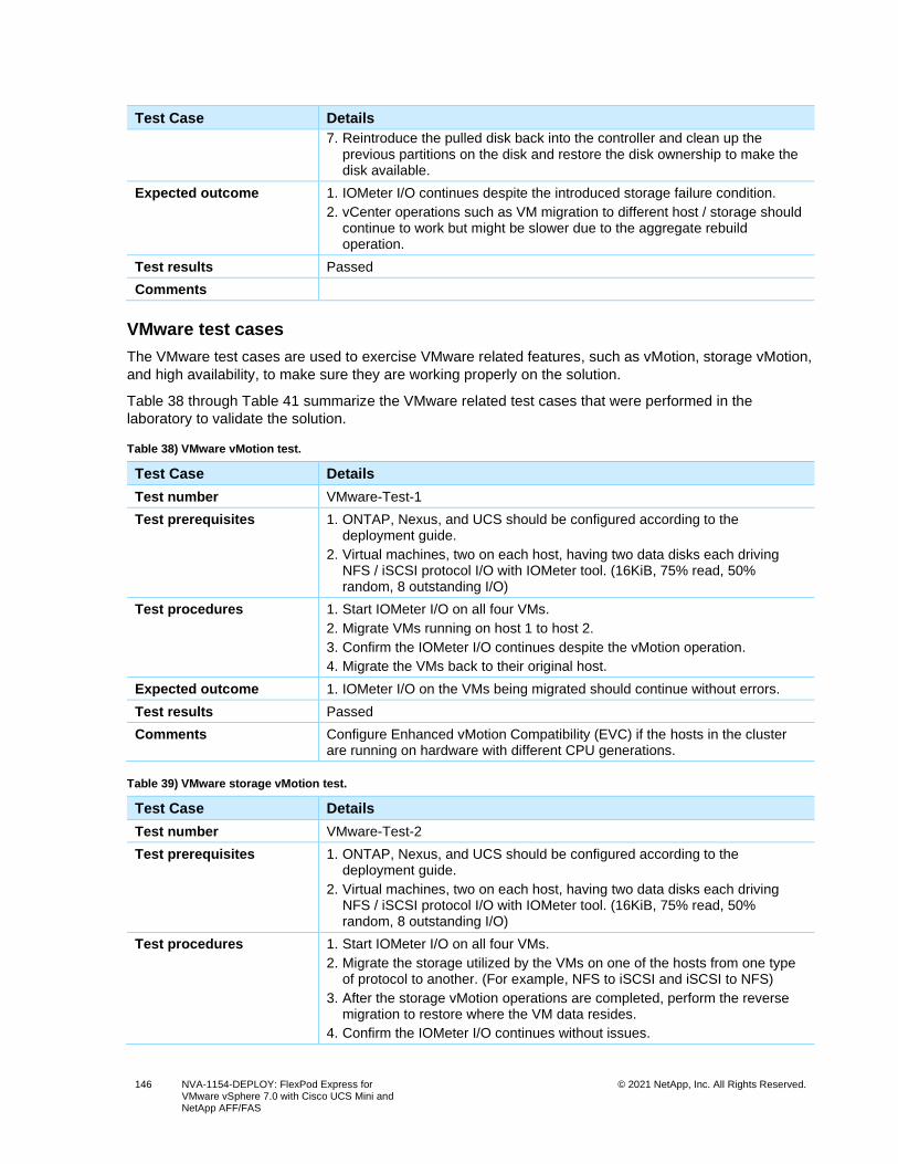
146 NVA-1154-DEPLOY: FlexPod Express for VMware vSphere 7.0 with Cisco UCS Mini and NetApp AFF/FAS
© 2021 NetApp, Inc. All Rights Reserved.
Test Case Details
7. Reintroduce the pulled disk back into the controller and clean up the previous partitions on the disk and restore the disk ownership to make the disk available.
Expected outcome 1. IOMeter I/O continues despite the introduced storage failure condition.
2. vCenter operations such as VM migration to different host / storage should continue to work but might be slower due to the aggregate rebuild operation.
Test results Passed
Comments
VMware test cases
The VMware test cases are used to exercise VMware related features, such as vMotion, storage vMotion,
and high availability, to make sure they are working properly on the solution.
Table 38 through Table 41 summarize the VMware related test cases that were performed in the
laboratory to validate the solution.
Table 38) VMware vMotion test.
Test Case Details
Test number VMware-Test-1
Test prerequisites 1. ONTAP, Nexus, and UCS should be configured according to the deployment guide.
2. Virtual machines, two on each host, having two data disks each driving NFS / iSCSI protocol I/O with IOMeter tool. (16KiB, 75% read, 50% random, 8 outstanding I/O)
Test procedures 1. Start IOMeter I/O on all four VMs.
2. Migrate VMs running on host 1 to host 2.
3. Confirm the IOMeter I/O continues despite the vMotion operation.
4. Migrate the VMs back to their original host.
Expected outcome 1. IOMeter I/O on the VMs being migrated should continue without errors.
Test results Passed
Comments Configure Enhanced vMotion Compatibility (EVC) if the hosts in the cluster are running on hardware with different CPU generations.
Table 39) VMware storage vMotion test.
Test Case Details
Test number VMware-Test-2
Test prerequisites 1. ONTAP, Nexus, and UCS should be configured according to the deployment guide.
2. Virtual machines, two on each host, having two data disks each driving NFS / iSCSI protocol I/O with IOMeter tool. (16KiB, 75% read, 50% random, 8 outstanding I/O)
Test procedures 1. Start IOMeter I/O on all four VMs.
2. Migrate the storage utilized by the VMs on one of the hosts from one type of protocol to another. (For example, NFS to iSCSI and iSCSI to NFS)
3. After the storage vMotion operations are completed, perform the reverse migration to restore where the VM data resides.
4. Confirm the IOMeter I/O continues without issues.
147 NVA-1154-DEPLOY: FlexPod Express for VMware vSphere 7.0 with Cisco UCS Mini and NetApp AFF/FAS
© 2021 NetApp, Inc. All Rights Reserved.
Test Case Details
Expected outcome 1. IOMeter I/O continues without issues.
Test results Passed
Comments With VAAI, storage vMotion is offloaded to storage.
Table 40) VMware high availability test.
Test Case Details
Test number VMware-Test-3
Test prerequisites 1. ONTAP, Nexus, and UCS should be configured according to the deployment guide.
2. Virtual machines, two on each host, having two data disks each driving NFS / iSCSI protocol I/O with IOMeter tool. (16KiB, 75% read, 50% random, 8 outstanding I/O)
Test procedures 1. Start IOMeter I/O on all four VMs.
2. Use the UCS Manager to reset one of the iSCSI SAN booted servers with the Power Cycle option.
3. Confirm IOMeter I/O on the VMs that were not residing on the host that went down was not affected.
4. Confirm VMware HA restarted the VMs that resided on the host that went down on the other host.
Expected outcome 1. IOMeter I/O continues on the VMs that were not impacted.
2. The VMs that were impacted were restarted on the other host.
Test results Passed
Comments
Table 41) VMware storage vMotion with storage QoS test.
Test Case Details
Test number VMware-Test-4
Test prerequisites 1. ONTAP, Nexus, and UCS should be configured according to the deployment guide.
2. Virtual machines, two on each host, having two data disks each driving NFS / iSCSI protocol I/O with IOMeter tool. (16KiB, 75% read, 50% random, 8 outstanding I/O)
Test procedures 1. Start IOMeter I/O on all four VMs.
2. Create a storage QoS policy with a maximum throughput limit and apply it to the data volumes used for IOMeter I/O. (For example, set the limit to 200MB/s if the IOMeter was driving around 400MB/s so you can easily see the differences with and without QoS.)
3. Confirm IOMeter I/O throughput was reduced as a result of the applied storage QoS policy.
4. Perform storage vMotion to move IOMeter data disks across datastores.
5. Remove the QoS policy from the data volumes.
Expected outcome 1. IOMeter I/O continues to run with reduced I/O throughput after the storage QoS policy was applied.
2. The storage vMotion operations took longer to complete with storage QoS limiting the volume throughput.
Test results Passed
148 NVA-1154-DEPLOY: FlexPod Express for VMware vSphere 7.0 with Cisco UCS Mini and NetApp AFF/FAS
© 2021 NetApp, Inc. All Rights Reserved.
Test Case Details
Comments Use storage QoS to help manage and meet workload performance requirements or to allocate storage I/O bandwidth between various applications if required.
Conclusion
FlexPod Express with UCS Mini is designed for small to midsize businesses, remote offices or branch
offices (ROBOs), and other businesses that require dedicated solutions. This validated solution uses a
combination of components from NetApp and Cisco and provides a step-by-step guide for easy adoption
and deployment of the converged infrastructure solution. By selecting different solution components and
scaling with additional components, the FlexPod Express with UCS Mini solution can be tailored for
specific business needs and can provide a highly reliable and flexible virtual infrastructure for application
deployments.
Appendix
iSCSI datastore configuration
If it is desirable to have an iSCSI-only configuration with iSCSI SAN boot and iSCSI datastores for the
solution, you can use the following procedures to create iSCSI datastores for the deployment of the
infrastructure VMs such as vCenter, VSC, Active IQ Unified Manager, and any additional VMs required by
the solution.
Note: It is a best practice to use VSC to provision new datastores after it is installed and configured.
Create NetApp FlexVol volumes in ONTAP for iSCSI datastores
To create a NetApp FlexVol® volume, enter the volume name, size, and the aggregate on which it exists.
To create two thin-provisioned volumes for VMware iSCSI datastores, run the following commands:
volume create -vserver Infra-SVM -volume iscsi_datastore_1 -aggregate aggr1_<clustername>_01 -
size 900GB -state online -policy default -space-guarantee none -percent-snapshot-space 0
volume create -vserver Infra-SVM -volume iscsi_datastore_2 -aggregate aggr1_<clustername>_02 -
size 900GB -state online -policy default -space-guarantee none -percent-snapshot-space 0
Enable deduplication schedule in ONTAP
To enable deduplication on the volumes once a day, run the following commands:
volume efficiency modify -vserver Infra-SVM -volume iscsi_datastore_1 -schedule sun-sat@0
volume efficiency modify -vserver Infra-SVM -volume iscsi_datastore_2 -schedule sun-sat@0
Create LUNs in ONTAP
To create two iSCSI datastore LUNs, run the following commands:
lun create -vserver Infra-SVM -volume iscsi_datastore_1 -lun iscsi-LUN-1 -size 800GB -ostype
vmware -space-reserve disabled
lun create -vserver Infra-SVM -volume iscsi_datastore_2 -lun iscsi-LUN-2 -size 800GB -ostype
vmware -space-reserve disabled
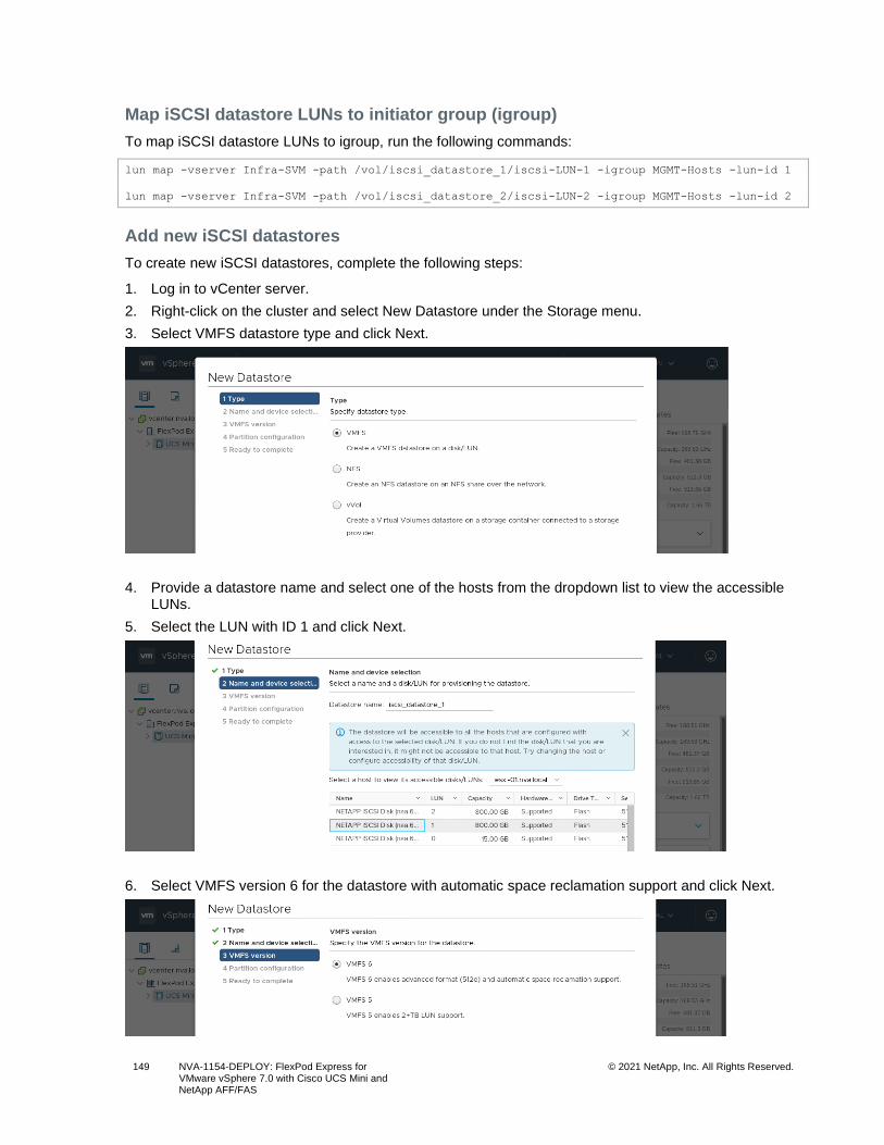
149 NVA-1154-DEPLOY: FlexPod Express for VMware vSphere 7.0 with Cisco UCS Mini and NetApp AFF/FAS
© 2021 NetApp, Inc. All Rights Reserved.
Map iSCSI datastore LUNs to initiator group (igroup)
To map iSCSI datastore LUNs to igroup, run the following commands:
lun map -vserver Infra-SVM -path /vol/iscsi_datastore_1/iscsi-LUN-1 -igroup MGMT-Hosts -lun-id 1
lun map -vserver Infra-SVM -path /vol/iscsi_datastore_2/iscsi-LUN-2 -igroup MGMT-Hosts -lun-id 2
Add new iSCSI datastores
To create new iSCSI datastores, complete the following steps:
1. Log in to vCenter server.
2. Right-click on the cluster and select New Datastore under the Storage menu.
3. Select VMFS datastore type and click Next.
4. Provide a datastore name and select one of the hosts from the dropdown list to view the accessible LUNs.
5. Select the LUN with ID 1 and click Next.
6. Select VMFS version 6 for the datastore with automatic space reclamation support and click Next.
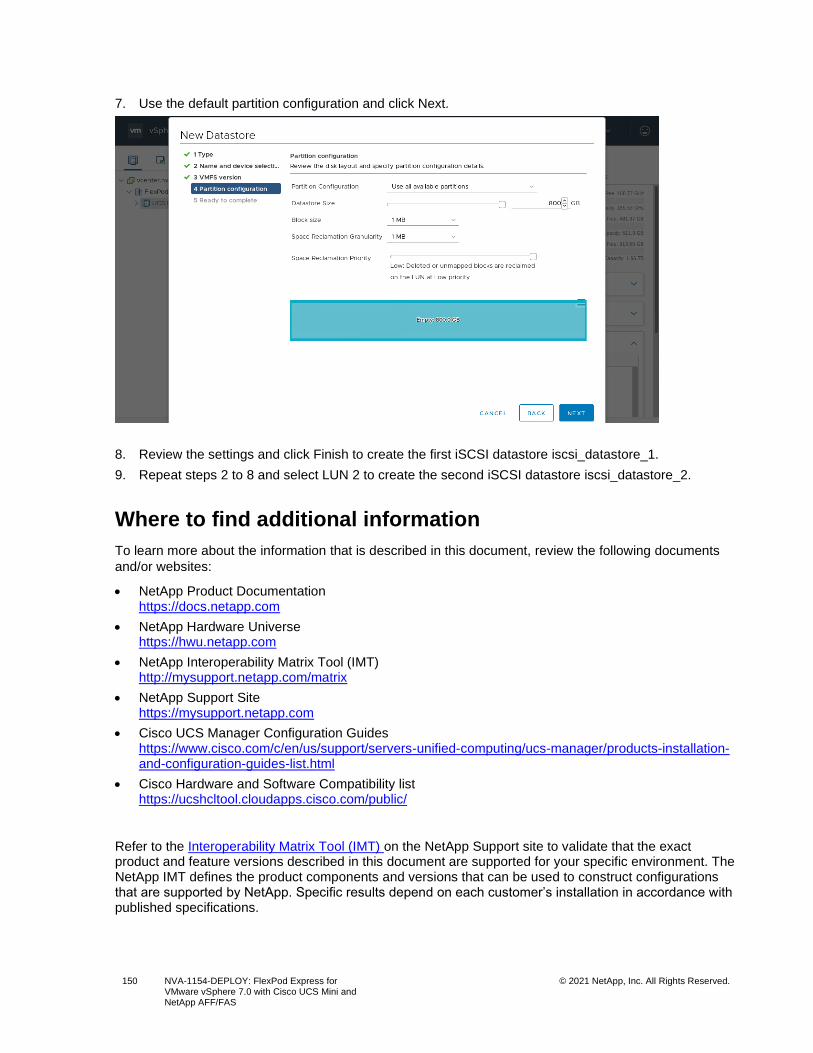
150 NVA-1154-DEPLOY: FlexPod Express for VMware vSphere 7.0 with Cisco UCS Mini and NetApp AFF/FAS
© 2021 NetApp, Inc. All Rights Reserved.
7. Use the default partition configuration and click Next.
8. Review the settings and click Finish to create the first iSCSI datastore iscsi_datastore_1.
9. Repeat steps 2 to 8 and select LUN 2 to create the second iSCSI datastore iscsi_datastore_2.
Where to find additional information
To learn more about the information that is described in this document, review the following documents
and/or websites:
• NetApp Product Documentation https://docs.netapp.com
• NetApp Hardware Universe https://hwu.netapp.com
• NetApp Interoperability Matrix Tool (IMT) http://mysupport.netapp.com/matrix
• NetApp Support Site https://mysupport.netapp.com
• Cisco UCS Manager Configuration Guides https://www.cisco.com/c/en/us/support/servers-unified-computing/ucs-manager/products-installation-and-configuration-guides-list.html
• Cisco Hardware and Software Compatibility list https://ucshcltool.cloudapps.cisco.com/public/
Refer to the Interoperability Matrix Tool (IMT) on the NetApp Support site to validate that the exact product and feature versions described in this document are supported for your specific environment. The NetApp IMT defines the product components and versions that can be used to construct configurations that are supported by NetApp. Specific results depend on each customer’s installation in accordance with published specifications.

151 NVA-1154-DEPLOY: FlexPod Express for VMware vSphere 7.0 with Cisco UCS Mini and NetApp AFF/FAS
© 2021 NetApp, Inc. All Rights Reserved.
Version history
Version Date Document version history
Version 1.0 January 2021 Initial release.
152 NVA-1154-DEPLOY: FlexPod Express for VMware vSphere 7.0 with Cisco UCS Mini and NetApp AFF/FAS
© 2021 NetApp, Inc. All Rights Reserved.
Copyright Information
Copyright © 2021 NetApp, Inc. All Rights Reserved. Printed in the U.S. No part of this document covered by copyright may be reproduced in any form or by any means—graphic, electronic, or mechanical, including photocopying, recording, taping, or storage in an electronic retrieval system—without prior written permission of the copyright owner.
Software derived from copyrighted NetApp material is subject to the following license and disclaimer:
THIS SOFTWARE IS PROVIDED BY NETAPP “AS IS” AND WITHOUT ANY EXPRESS OR IMPLIED WARRANTIES, INCLUDING, BUT NOT LIMITED TO, THE IMPLIED WARRANTIES OF MERCHANTABILITY AND FITNESS FOR A PARTICULAR PURPOSE, WHICH ARE HEREBY DISCLAIMED. IN NO EVENT SHALL NETAPP BE LIABLE FOR ANY DIRECT, INDIRECT, INCIDENTAL, SPECIAL, EXEMPLARY, OR CONSEQUENTIAL DAMAGES (INCLUDING, BUT NOT LIMITED TO, PROCUREMENT OF SUBSTITUTE GOODS OR SERVICES; LOSS OF USE, DATA, OR PROFITS; OR BUSINESS INTERRUPTION) HOWEVER CAUSED AND ON ANY THEORY OF LIABILITY, WHETHER IN CONTRACT, STRICT LIABILITY, OR TORT (INCLUDING NEGLIGENCE OR OTHERWISE) ARISING IN ANY WAY OUT OF THE USE OF THIS SOFTWARE, EVEN IF ADVISED OF THE POSSIBILITY OF SUCH DAMAGE.
NetApp reserves the right to change any products described herein at any time, and without notice. NetApp assumes no responsibility or liability arising from the use of products described herein, except as expressly agreed to in writing by NetApp. The use or purchase of this product does not convey a license under any patent rights, trademark rights, or any other intellectual property rights of NetApp.
The product described in this manual may be protected by one or more U.S. patents, foreign patents, or pending applications.
Data contained herein pertains to a commercial item (as defined in FAR 2.101) and is proprietary to NetApp, Inc. The U.S. Government has a non-exclusive, non-transferrable, non-sublicensable, worldwide, limited irrevocable license to use the Data only in connection with and in support of the U.S. Government contract under which the Data was delivered. Except as provided herein, the Data may not be used, disclosed, reproduced, modified, performed, or displayed without the prior written approval of NetApp, Inc. United States Government license rights for the Department of Defense are limited to those rights identified in DFARS clause 252.227-7015(b).
Trademark Information
NETAPP, the NETAPP logo, and the marks listed at http://www.netapp.com/TM are trademarks of NetApp, Inc. Other company and product names may be trademarks of their respective owners.
NVA-1154-DEPLOY-0121
Related Documents