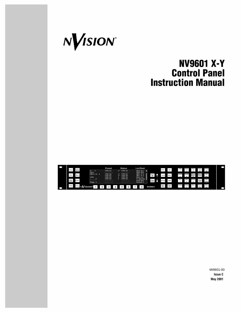
MI9601-00 Issue C May 2001 NVision2 ision2 NV9601 Clear Info Def State Take Chop Salvo Menu X-Y Multi 1 2 3 4 5 6 7 8 Preset Status Lev/Dest Page Up VTR 1 HDDR 4 Ctrl 7 FrStor Aux SrStor 0 Disk 2 SDDR 5 Edit 8 Studio 9 SDCam SDMon 6 HDCam HDMon CGen Xmit Test 3 Cam SD Remt Key TCine HD Sat Ctrl Net AESX Mstr VIS Prot Lock Scroll Dest Src Hold Page Down Prev Src Free Src VTR-02 -------- VTR-02 VTR-02 VTR-02 VTR-02 -------- -------- HDVideo SDVideo AES 1/2 AES 3/4 Control TimeCode AnVideo AnAudio L* VTR-01 -------- L* VTR-01 L* VTR-01 L VTR-01 L VTR-01 -------- -------- X - Y Dest Monitor 1 VTR _ _ _2 Page 1 NV9601 X-Y Control Panel Instruction Manual

Welcome message from author
This document is posted to help you gain knowledge. Please leave a comment to let me know what you think about it! Share it to your friends and learn new things together.
Transcript
MI9601-00Issue C
May 2001
NVision2ision2 NV9601
Clear
Info
DefState
Take Chop
Salvo
Menu
X-YMulti
1 2 3 4 5 6 7 8
Preset Status Lev/Dest
PageUp
VTR
1
HDDR
4
Ctrl
7
FrStor AuxSrStor
0
Disk
2
SDDR
5
Edit
8
Studio
9
SDCamSDMon
6
HDCamHDMon
CGenXmit
Test
3
Cam
SD
Remt
Key
TCine
HD
Sat
Ctrl
Net
AESX
Mstr
VIS
Prot
Lock
Scroll
Dest
Src
HoldPageDown
PrevSrc
FreeSrc
VTR-02--------VTR-02VTR-02VTR-02VTR-02----------------
HDVideoSDVideoAES 1/2AES 3/4ControlTimeCodeAnVideoAnAudio
L* VTR-01 --------L* VTR-01L* VTR-01L VTR-01L VTR-01 -------- --------
X - YDestMonitor 1
VTR_ _ _2
Page 1
NV9601 X-YControl Panel
Instruction Manual

MI9601-00 • Issue C • May 2001 • FRONT MATTER
Page ii
FRONT MATTER
COPYRIGHT AND TRADEMARKS
Copyright ©�2000, NVISION Inc. All rights reserved. Printed in USA.
REVISION HISTORY
DISCLAIMER OF LIABILITY
Contents of this publication are current as of the publication date. NVISION reserves the right to change the contents without prior notice. In no event shall NVISION be liable for any damages resulting from loss of data, loss of use, or loss of profits and NVISION further disclaims any and all liability for indirect, incidental, special, consequential or other similar damages. This disclaimer of liability applies to all products, publications, and services during and after the warranty period.
REVISION DATE REASON FOR CHANGE
Revision A March, 2000 Initial Release.
Revision B August, 2000 Added level mapping. (Spec H)
Revision C May, 2001 Added ability to link PDF with related PDFs on NV9000 Manuals CD
NVISION, Inc125 Crown Point CourtGrass Valley, CA 95945, USAIn USA and Canada: 1-800-719-1900Outside USA and Canada: 530-265-1000FAX: 530-265-1010 or 530-265-1021Email: [email protected]
MI9601-00 • Issue C • May 2001 • FRONT MATTER
ABOUT THIS MANUAL
This manual provides overview, installation, operation, and maintenance information about the product. Sections included are the following:
• Section 1: Getting Started - Unpacking, product overview, and specifications.
• Section 2: Installation - Physical installation, cabling, and power on.
• Section 3: Operation - Step-by-step operating procedures.
• Section 4: Maintenance - Maintenance, troubleshooting, repair, and replacement.
• Section 5: Notes - Late-breaking information about the product.
RELATED PUBLICATIONS
Related manuals and their publication numbers are listed below. These publications can be ordered from NVISION , or they may be downloaded from at www.nvision1.com
NV9000 Panels Tutorial MI9600-00An electronic PDF manual explaining how to operatethe NV9601 and other NV9000 panels.
NV9000 Configuration Manager User GuideExplains how to configure the NV9000 server and use the NV9601 Configuration Editor.
QUICK START
If you are setting up the product for the first time and wish to do so as quickly as possible, do the following:
1. Check the Notes section for late-breaking changes or information.
2. See "SECTION 2: NV9601 Installation" to install the equipment.
3. See "Section 3: NV9601 Operation" to learn how to operate the product.
Title/Description Publication Number
Page iii

MI9601-00 • Issue C • May 2001 • FRONT MATTER
d,
d,
IMPORTANT SAFEGUARDS AND NOTICES
The following pages provide important safety guidelines for operators and service personnel. Specific warnings and cautions appear throughout the manual where they apply. Please read and follow this important information, especially those instructions related to the risk of electric shock or injury to persons.
Symbols and Their Meanings
The lightning flash with arrowhead symbol within an equilateral triangle alerts the user to the presence of dangerous voltages within the product's enclosure that may be of sufficient magnitude to constitute a risk of electric shock to persons.
The exclamation point within an equilateral triangle alerts the user to the presence of important operating and maintenance/service instructions.
The Ground symbol represents a protective grounding terminal. Such a terminal must be connected to earth ground prior to making any other connections to the equipment.
The fuse symbol indicates that the fuse referenced in the text must be replaced with one having the ratings indicated.
The presence of this symbol in or on NVISION equipment means that it has been designetested and certified as complying with applicable Underwriter's Laboratory (USA) regulations and recommendations.
The presence of this symbol in or on NVISION equipment means that it has been designetested and certified as essentially complying with all applicable European Union (CE) regulations and recommendations.
Warning: Any instructions in this manual that require opening the equipment cover or enclosure are for use by qualified service personnel only. To reduce the risk of electric shock, do not perform any service other than that contained in the operating instructions unless you are qualified to do so.
Page iv

MI9601-00 • Issue C • May 2001 • FRONT MATTER
General Warnings
A warning indicates a possible hazard to personnel which may cause injury or death. Observe the following general warnings when using or working on this equipment.
• Heed all warnings on the unit and in the operating instructions.
• Do not use this equipment in or near water.
• This equipment is grounded through the grounding conductor of the power cord. To avoid electrical shock, plug the power cord into a properly wired receptacle before connecting the equipment inputs or outputs.
• Route power cords and other cables so they are not likely to be damaged.
• Disconnect power before cleaning the equipment. Do not use liquid or aerosol cleaners; use only a damp cloth.
• Dangerous voltages may exist at several points in this equipment. To avoid injury, do not touch exposed connections and components while power is on.
• Do not wear rings or wristwatches when troubleshooting high current circuits such as the power supplies.
• To avoid fire hazard, use only the specified fuse(s) with the correct type number, voltage and current ratings as referenced in the appropriate locations in the service instructions or on the equipment. Always refer fuse replacements to qualified service personnel.
• To avoid explosion, do not operate this equipment in an explosive atmosphere.
• Have qualified service personnel perform safety checks after any service.
General Cautions
A caution indicates a possible hazard to equipment that could result in equipment damage. Observe the following cautions when operating or working on this equipment.
• When installing this equipment, do not attach the power cord to building surfaces.
• To prevent damage to equipment when replacing fuses, locate and correct the problem that caused the fuse to blow before re-applying power.
• Use only the specified replacement parts.
• Follow static precautions at all times when handling this equipment.
• This product should only be powered as described in the manual. To prevent equipment damage, select the proper line voltage on the power supply(ies) as described in the installation documentation.
• To prevent damage to the equipment, read the instructions in the equipment manual for proper input voltage range selection.
Page v

MI9601-00 • Issue C • May 2001 • FRONT MATTER
NORTH AMERICAN POWER SUPPLY CORDS
The North American power cords supplied with this equipment have a molded grounding plug (NEMA 5-15P) at one end and molded grounding receptacle (IEC 320-C13) at the other end (see figure below). Conductors are CEE color-coded: Light blue (neutral), Brown (line) and Green or Green/Yellow (ground). Operation of this equipment at voltages exceeding 130 VAC will require power supply cords which comply with NEMA configurations.
The power cords supplied with this equipment provide the only means of mains disconnection. The socket-outlet shall be installed near the equipment and shall be easily accessible.
INTERNATIONAL POWER SUPPLY CORDS
The International power cords supplied with this equipment have a molded grounding receptacle (IEC 320-C13) at one end and stripped conductors (50/5 mm) at the other end (see figure below). Conductors are CEE color-coded: Light blue (neutral), Brown (line) and Green/Yellow (ground). Other IEC 320-C13 type power supply cords can be used if they comply with the safety regulations of the country in which they are installed.
The power cords supplied with this equipment provide the only means of mains disconnection. The socket-outlet shall be installed near the equipment and shall be easily accessible.
����
�����
����� �������������������������������������
���
�����
����
�����
����� ����������������������������
���
�����
Page vi

MI9601-00 • Issue C • May 2001 • FRONT MATTER
FCC (USA) COMPLIANCE STATEMENT
This equipment has been tested and found to comply with the limits for a Class A digital device, pursuant to Part 15 of the FCC Rules. These limits are designed to provide reasonable protection against harmful interference when the equipment is operated in a commercial environment.
This equipment generates, uses and can radiate radio frequency energy and, if not installed and used in accordance with the instruction manual, may cause harmful interference in which case the user will be required to correct the interference at their own expense.
FCC Emission Limits
This device complies with Part 15 of the FCC rules. Operation is subject to the following two conditions:
1. This device may not cause harmful interference; and
2. This device must accept any interference received, including interference that may cause undesirable operation.
EUROPEAN COMMUNITY (CE) DECLARATION OF CONFORMANCE
All of the equipment described in this manual has been designed to conform with the required safety and emissions standards of the European Community. Products tested and verified to meet these standards are marked as required by law with the CE mark (See “Symbols and Their Meanings” above.)
When shipped into member countries of the European Community, this equipment is accompanied by authentic copies of original Declarations of Conformance on file in NVISION offices in Grass Valley, California USA.
Page vii

MI9601-00 • Issue C • May 2001 • FRONT MATTER
TECHNICAL SUPPORT
NVISION has made every effort to ensure that the equipment you receive is in perfect working order. In the event that problems arise which you cannot resolve, or if there are any questions regarding this equipment or information about other products manufactured by NVISION, please contact your local representative or contact NVISIONdirectly through one of the appropriate means listed below:
Telephone:* Main Number - 1-530-265-1000*Technical Support - 1-530-265-1059Sales - 1-800-719-1900/1-530-265-1000
Facsimile: Main Number - 1-530-265-1010Sales - 1-530-265-1021
Email: Technical Support - [email protected] - [email protected]
Web Site: http://www.nvision1.com
Mail: NVISION IncP.O. Box 1658Nevada City, CA 95959, USA
Shipping:** NVISION125 Crown Point CourtGrass Valley, CA 95945, USA
* Available from 8:00 a.m. to 5:00 p.m., Monday-Friday, Pacific time.** Material Return Authorization required before any equipment is returned.
Page viii

MI9601-00 • Issue C • May 2001 • CONTENTS
Content Page
TABLE OF CONTENTS
FRONT MATTERCOPYRIGHT AND TRADEMARKS . . . . . . . . . . . . . . . . . . . . . . . . . . . . . . . . . . . . . . . . . . . . . . . . ii
REVISION HISTORY . . . . . . . . . . . . . . . . . . . . . . . . . . . . . . . . . . . . . . . . . . . . . . . . . . . . . . . . . ii
DISCLAIMER OF LIABILITY . . . . . . . . . . . . . . . . . . . . . . . . . . . . . . . . . . . . . . . . . . . . . . . . . . . . ii
ABOUT THIS MANUAL. . . . . . . . . . . . . . . . . . . . . . . . . . . . . . . . . . . . . . . . . . . . . . . . . . . . . . . iii
RELATED PUBLICATIONS . . . . . . . . . . . . . . . . . . . . . . . . . . . . . . . . . . . . . . . . . . . . . . . . . . . . iii
QUICK START . . . . . . . . . . . . . . . . . . . . . . . . . . . . . . . . . . . . . . . . . . . . . . . . . . . . . . . . . . . . iii
IMPORTANT SAFEGUARDS AND NOTICES . . . . . . . . . . . . . . . . . . . . . . . . . . . . . . . . . . . . . . . . . iv
Symbols and Their Meanings . . . . . . . . . . . . . . . . . . . . . . . . . . . . . . . . . . . . . . . . . . . iv
General Warnings . . . . . . . . . . . . . . . . . . . . . . . . . . . . . . . . . . . . . . . . . . . . . . . . . . . . v
General Cautions. . . . . . . . . . . . . . . . . . . . . . . . . . . . . . . . . . . . . . . . . . . . . . . . . . . . . v
NORTH AMERICAN POWER SUPPLY CORDS . . . . . . . . . . . . . . . . . . . . . . . . . . . . . . . . . . . . . . . vi
INTERNATIONAL POWER SUPPLY CORDS . . . . . . . . . . . . . . . . . . . . . . . . . . . . . . . . . . . . . . . . . vi
FCC (USA) COMPLIANCE STATEMENT . . . . . . . . . . . . . . . . . . . . . . . . . . . . . . . . . . . . . . . . . . . . vii
FCC Emission Limits . . . . . . . . . . . . . . . . . . . . . . . . . . . . . . . . . . . . . . . . . . . . . . . . . vii
EUROPEAN COMMUNITY (CE) DECLARATION OF CONFORMANCE . . . . . . . . . . . . . . . . . . . . . . . . . vii
TECHNICAL SUPPORT. . . . . . . . . . . . . . . . . . . . . . . . . . . . . . . . . . . . . . . . . . . . . . . . . . . . . . .viii
SECTION 1:GETTING STARTED
INTRODUCTION . . . . . . . . . . . . . . . . . . . . . . . . . . . . . . . . . . . . . . . . . . . . . . . . . . . . . . . . . . 1-2
RECEIVING AND UNPACKING. . . . . . . . . . . . . . . . . . . . . . . . . . . . . . . . . . . . . . . . . . . . . . . . . 1-2
NV9601 X-Y CONTROL PANEL OVERVIEW . . . . . . . . . . . . . . . . . . . . . . . . . . . . . . . . . . . . . . . . 1-3
NV9601 Modes of Operation . . . . . . . . . . . . . . . . . . . . . . . . . . . . . . . . . . . . . . . . . . . 1-3
NV9601 X-Y Mode . . . . . . . . . . . . . . . . . . . . . . . . . . . . . . . . . . . . . . . . . . . . 1-3
NV9601 Multi-Destination Mode . . . . . . . . . . . . . . . . . . . . . . . . . . . . . . . . . . 1-3
NV9601 Configurable Functions. . . . . . . . . . . . . . . . . . . . . . . . . . . . . . . . . . . . . . . . . 1-4
Other NV9601 X-Y Control Panel Features. . . . . . . . . . . . . . . . . . . . . . . . . . . . . . . . . . 1-4
NV9601 Button Use . . . . . . . . . . . . . . . . . . . . . . . . . . . . . . . . . . . . . . . . . . . . . . . . . 1-4
NV9601 FRONT PANEL DESCRIPTION . . . . . . . . . . . . . . . . . . . . . . . . . . . . . . . . . . . . . . . . . . . 1-5
NV9601 REAR PANEL DESCRIPTION . . . . . . . . . . . . . . . . . . . . . . . . . . . . . . . . . . . . . . . . . . . . 1-6
NV9601 X-Y CONTROL PANEL SPECIFICATIONS . . . . . . . . . . . . . . . . . . . . . . . . . . . . . . . . . . . . 1-7
Page ix
MI9601-00 • Issue C • May 2001 • CONTENTS
Content Page
TABLE OF CONTENTS
SECTION 2:NV9601 INSTALLATION
CONFIGURING THE NV9601 PANEL. . . . . . . . . . . . . . . . . . . . . . . . . . . . . . . . . . . . . . . . . . . . . 2-2
INSTALLING KEY CAP LEGENDS . . . . . . . . . . . . . . . . . . . . . . . . . . . . . . . . . . . . . . . . . . . . . . . 2-3
Key Cap Legend Meanings . . . . . . . . . . . . . . . . . . . . . . . . . . . . . . . . . . . . . . . . . . . . 2-5
Legend Installation Procedure . . . . . . . . . . . . . . . . . . . . . . . . . . . . . . . . . . . . . . . . . . 2-6
PHYSICALLY INSTALLING THE NV9601 PANEL . . . . . . . . . . . . . . . . . . . . . . . . . . . . . . . . . . . . . 2-8
CONNECTING THE PANEL TO THE ENVY SERVER . . . . . . . . . . . . . . . . . . . . . . . . . . . . . . . . . . . 2-9
10 Base T Connection. . . . . . . . . . . . . . . . . . . . . . . . . . . . . . . . . . . . . . . . . . . . . . . . 2-9
10 Base 2 Connection. . . . . . . . . . . . . . . . . . . . . . . . . . . . . . . . . . . . . . . . . . . . . . . 2-10
APPLYING AC POWER TO THE PANEL . . . . . . . . . . . . . . . . . . . . . . . . . . . . . . . . . . . . . . . . . . 2-11
PANEL BOOT UP . . . . . . . . . . . . . . . . . . . . . . . . . . . . . . . . . . . . . . . . . . . . . . . . . . . . . . . . 2-12
SETTING THE PANEL ID AT THE PANEL . . . . . . . . . . . . . . . . . . . . . . . . . . . . . . . . . . . . . . . . . 2-13
SECTION 3:NV9601 OPERATION
CONVENTIONS USED IN THIS SECTION . . . . . . . . . . . . . . . . . . . . . . . . . . . . . . . . . . . . . . . . . . 3-2
NV9601 OPERATIONAL QUICK REFERENCE . . . . . . . . . . . . . . . . . . . . . . . . . . . . . . . . . . . . . . . 3-2
NV9601 GENERAL OPERATING INFORMATION . . . . . . . . . . . . . . . . . . . . . . . . . . . . . . . . . . . . . 3-4
Numeric Entry General Information . . . . . . . . . . . . . . . . . . . . . . . . . . . . . . . . . . . . . . 3-4
NV9601 BUTTON DESCRIPTIONS . . . . . . . . . . . . . . . . . . . . . . . . . . . . . . . . . . . . . . . . . . . . . . 3-5
NV9601 MENU DESCRIPTION. . . . . . . . . . . . . . . . . . . . . . . . . . . . . . . . . . . . . . . . . . . . . . . . . 3-8
Software. . . . . . . . . . . . . . . . . . . . . . . . . . . . . . . . . . . . . . . . . . . . . . . . . . . . . . . . . 3-8
User. . . . . . . . . . . . . . . . . . . . . . . . . . . . . . . . . . . . . . . . . . . . . . . . . . . . . . . . . . . . 3-8
Panel . . . . . . . . . . . . . . . . . . . . . . . . . . . . . . . . . . . . . . . . . . . . . . . . . . . . . . . . . . . 3-9
Illumination . . . . . . . . . . . . . . . . . . . . . . . . . . . . . . . . . . . . . . . . . . . . . . . . . . . . . 3-10
Button Illumination . . . . . . . . . . . . . . . . . . . . . . . . . . . . . . . . . . . . . . . . . . 3-10
Display Illumination . . . . . . . . . . . . . . . . . . . . . . . . . . . . . . . . . . . . . . . . . 3-11
Salvo . . . . . . . . . . . . . . . . . . . . . . . . . . . . . . . . . . . . . . . . . . . . . . . . . . . . . . . . . . 3-11
Force Release. . . . . . . . . . . . . . . . . . . . . . . . . . . . . . . . . . . . . . . . . . . . . . . . . . . . 3-11
Exit . . . . . . . . . . . . . . . . . . . . . . . . . . . . . . . . . . . . . . . . . . . . . . . . . . . . . . . . . . . 3-12
NV9601 SALVO DESCRIPTION . . . . . . . . . . . . . . . . . . . . . . . . . . . . . . . . . . . . . . . . . . . . . . . 3-12
Create, Save, and Clear a Local Salvo . . . . . . . . . . . . . . . . . . . . . . . . . . . . . . . . . . . 3-12
Executing a Salvo . . . . . . . . . . . . . . . . . . . . . . . . . . . . . . . . . . . . . . . . . . . . . . . . . 3-15
Page x

MI9601-00 • Issue C • May 2001 • CONTENTS
Content Page
TABLE OF CONTENTS
NV9601 OPERATING PROCEDURES . . . . . . . . . . . . . . . . . . . . . . . . . . . . . . . . . . . . . . . . . . . .3-16
NV9601 X-Y Mode of Operation . . . . . . . . . . . . . . . . . . . . . . . . . . . . . . . . . . . . . . . . .3-16
X-Y Mode Display Description. . . . . . . . . . . . . . . . . . . . . . . . . . . . . . . . . . . 3-17
Performing a Take (X-Y Mode) . . . . . . . . . . . . . . . . . . . . . . . . . . . . . . . . . . 3-19
Selecting Levels (X-Y Mode) . . . . . . . . . . . . . . . . . . . . . . . . . . . . . . . . . . . 3-20
Holding Levels (X-Y Mode). . . . . . . . . . . . . . . . . . . . . . . . . . . . . . . . . . . . . 3-20
Mapping Levels . . . . . . . . . . . . . . . . . . . . . . . . . . . . . . . . . . . . . . . . . . . . 3-20
Saving Presets (X-Y Mode). . . . . . . . . . . . . . . . . . . . . . . . . . . . . . . . . . . . . 3-21
Performing a Single Level (Breakaway) Switch (X-Y Mode). . . . . . . . . . . . . . . 3-22
Performing Multiple Source Breakaways (X-Y Mode) . . . . . . . . . . . . . . . . . . . 3-23
Multi-Destination Mode of Operation . . . . . . . . . . . . . . . . . . . . . . . . . . . . . . . . . . . . .3-24
Multi-Destination Mode Display Description . . . . . . . . . . . . . . . . . . . . . . . . . 3-25
Performing a Take (Multi-Destination Mode) . . . . . . . . . . . . . . . . . . . . . . . . 3-26
Performing a One Time Salvo (Multi-Destination Mode) . . . . . . . . . . . . . . . . . 3-27
Performing a Gang or Dub Switch (Multi-Destination Mode) . . . . . . . . . . . . . . 3-28
Programming a Destination Position . . . . . . . . . . . . . . . . . . . . . . . . . . . . . . 3-29
Clearing a Programmed Destination Position . . . . . . . . . . . . . . . . . . . . . . . . 3-30
SECTION 4:NV9601 MAINTENANCE
MAINTENANCE . . . . . . . . . . . . . . . . . . . . . . . . . . . . . . . . . . . . . . . . . . . . . . . . . . . . . . . . . . 4-2
TROUBLESHOOTING . . . . . . . . . . . . . . . . . . . . . . . . . . . . . . . . . . . . . . . . . . . . . . . . . . . . . . . 4-2
Initialization Routine . . . . . . . . . . . . . . . . . . . . . . . . . . . . . . . . . . . . . . . . . . . . . . . . 4-2
Firmware Menu. . . . . . . . . . . . . . . . . . . . . . . . . . . . . . . . . . . . . . . . . . . . . . . . . . . . 4-3
Panel ID . . . . . . . . . . . . . . . . . . . . . . . . . . . . . . . . . . . . . . . . . . . . . . . . . . 4-4
Software Versions . . . . . . . . . . . . . . . . . . . . . . . . . . . . . . . . . . . . . . . . . . . . 4-4
Panel Tests . . . . . . . . . . . . . . . . . . . . . . . . . . . . . . . . . . . . . . . . . . . . . . . . 4-5
Loss of Contact With Server . . . . . . . . . . . . . . . . . . . . . . . . . . . . . . . . . . . . . . . . . . . 4-5
ORDERING REPLACEMENT ASSEMBLIES. . . . . . . . . . . . . . . . . . . . . . . . . . . . . . . . . . . . . . . . . 4-6
SECTION 5:NOTES
INTRODUCTION . . . . . . . . . . . . . . . . . . . . . . . . . . . . . . . . . . . . . . . . . . . . . . . . . . . . . . . . . . 5-2
Page xi


MI9601-00 • Issue C • May 2001 • Section 1: Getting Started
SECTION 1: Getting StartedThis section presents an overview of the NV9601 X-Y Control Panel manufactured by NVISION, including descriptions of panel features, modes, buttons, and specifications.
Topics covered by this section are listed below:
�
INTRODUCTION . . . . . . . . . . . . . . . . . . . . . . . . . . . . . . . . . . . . . . . . . . . . . . . . . . . . . . . . . . 1-2
RECEIVING AND UNPACKING. . . . . . . . . . . . . . . . . . . . . . . . . . . . . . . . . . . . . . . . . . . . . . . . . 1-2
NV9601 X-Y CONTROL PANEL OVERVIEW . . . . . . . . . . . . . . . . . . . . . . . . . . . . . . . . . . . . . . . . 1-3
NV9601 Modes of Operation . . . . . . . . . . . . . . . . . . . . . . . . . . . . . . . . . . . . . . . . . . . . 1-3
NV9601 Configurable Functions. . . . . . . . . . . . . . . . . . . . . . . . . . . . . . . . . . . . . . . . . . 1-4
Other NV9601 X-Y Control Panel Features. . . . . . . . . . . . . . . . . . . . . . . . . . . . . . . . . . . 1-4
NV9601 Button Use . . . . . . . . . . . . . . . . . . . . . . . . . . . . . . . . . . . . . . . . . . . . . . . . . . 1-4
NV9601 FRONT PANEL DESCRIPTION . . . . . . . . . . . . . . . . . . . . . . . . . . . . . . . . . . . . . . . . . . . 1-5
NV9601 REAR PANEL DESCRIPTION . . . . . . . . . . . . . . . . . . . . . . . . . . . . . . . . . . . . . . . . . . . . 1-6
NV9601 X-Y CONTROL PANEL SPECIFICATIONS . . . . . . . . . . . . . . . . . . . . . . . . . . . . . . . . . . . . 1-7
Contents Page
Page 1-1

MI9601-00 • Issue C • May 2001 • Section 1: Getting Started
INTRODUCTION
The NV9601 X-Y Control Panel manufactured by NVISION is a router control panel that works with the NV9000 router control system. Capable of operating in a number of different modes, the NV9601 panel is configured in software using the NV9000 server. An illustration of the panel is presented below in Figure 1-1.
Figure 1-1. The NV9601 X-Y Control Panel
RECEIVING AND UNPACKING
Inspect the shipping container for damage. If you find any, unpack the contents and inspect it. If the contents are damaged, notify the carrier immediately.
As you unpack the shipping container, look first for the packing slip and compare it against the contents to make sure you received everything you ordered. If anything is missing or if you find equipment damage unrelated to shipping, contact NVISION. For Technical Support contact information, see "TECHNICAL SUPPORT" on page viii in the front of this manual.
�������� ������
���
� ��
��������
�� ����
����
� �
���
�����
� � � ! � " #
$�%� ����% &�'�%�
$()�
��*
�
+��*
����
"
,����� -�.������
�
��%�
�
���*
!
/0��
#
���0��
�
���1����
�
+��1+���
�2 �1��
�%�
�
�1
��
*1�
34
���
+�
��
����
��
-/��
�%��
���
$���
&�5�
�5����
�%�
��5
+��0$(��6
$����5
,���5
������� � � � � � � �������������������������� � � � � � � �� � � � � � � �
���� ���� ��� ������ ���� ��� ����� ������� �����
�� ������� � � � � � � �
�� �������� ������� ������� ������� � � � � � � �� � � � � � � �
� � �� �! �� � �
���" " "�
#$%� �
Page 1-2

MI9601-00 • Issue C • May 2001 • Section 1: Getting Started
NV9601 X-Y CONTROL PANEL OVERVIEW
The NV9601 is an X-Y Control Panel that provides an interface to the NV9000 Router Control System. Although designed for installation in a standard 19” electronic equipment rack, the 2 RU high panel may be placed on any flat level surface.
The panel uses a display with brightness controls to provide visibility in all lighting conditions. Up to eight lines are viewable on the display. Each line may contain up to four fields of eight characters each.
Programmable front panel buttons provide source and destination selection, and function control. The buttons also include brightness control to optimize visibility. Key caps hold easily changed button legends.
NV9601 Modes of Operation
The panel operates in either an X-Y (single source/destination) mode or a Multi-Destination mode. A single button provides toggling between modes. Also, through the NV9601 Configuration Editor, the NV9601 is configurable:
• To be single mode only.
• To control either all sources and destinations or a subset of them.
• To be single destination only.
These modes of operation are explained below.
NV9601 X-Y Mode
In X-Y mode, the display shows up to eight levels of status information. Additional levels, if any, are viewable by pressing the Page Up/Page Dn keys.
NV9601 Multi-Destination Mode
In Multi-Destination mode, the display monitors the status of up to eight destinations. As in the X-Y mode, additional destinations, if any, are viewable by pressing the Page Up/Page Dn keys.
Page 1-3
MI9601-00 • Issue C • May 2001 • Section 1: Getting Started
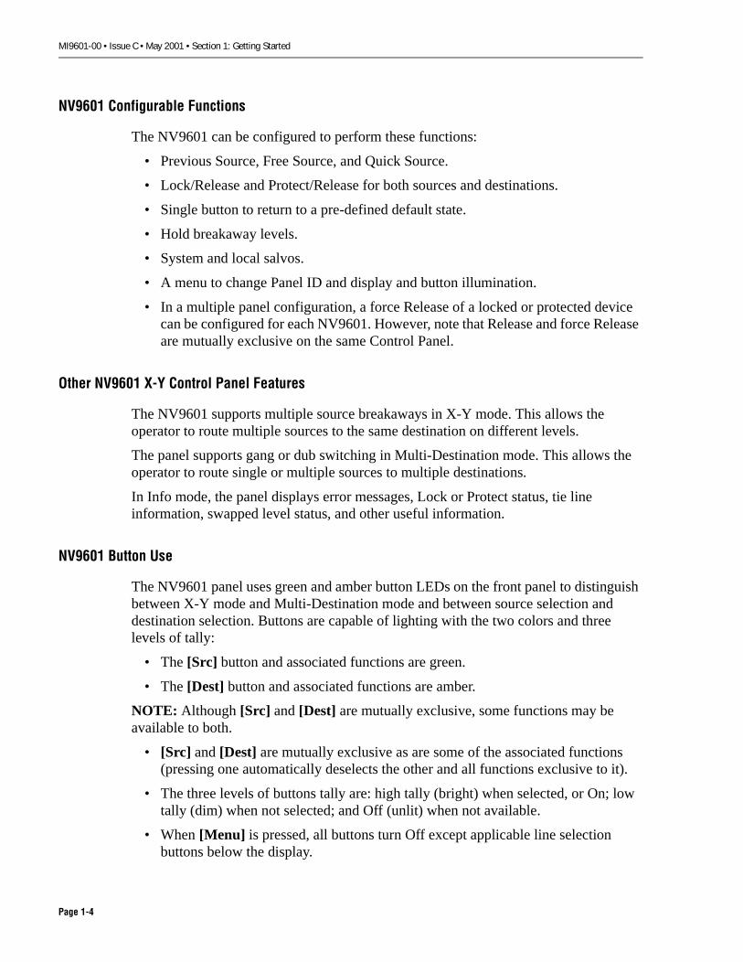
NV9601 Configurable Functions
The NV9601 can be configured to perform these functions:
• Previous Source, Free Source, and Quick Source.
• Lock/Release and Protect/Release for both sources and destinations.
• Single button to return to a pre-defined default state.
• Hold breakaway levels.
• System and local salvos.
• A menu to change Panel ID and display and button illumination.
• In a multiple panel configuration, a force Release of a locked or protected device can be configured for each NV9601. However, note that Release and force Release are mutually exclusive on the same Control Panel.
Other NV9601 X-Y Control Panel Features
The NV9601 supports multiple source breakaways in X-Y mode. This allows the operator to route multiple sources to the same destination on different levels.
The panel supports gang or dub switching in Multi-Destination mode. This allows the operator to route single or multiple sources to multiple destinations.
In Info mode, the panel displays error messages, Lock or Protect status, tie line information, swapped level status, and other useful information.
NV9601 Button Use
The NV9601 panel uses green and amber button LEDs on the front panel to distinguish between X-Y mode and Multi-Destination mode and between source selection and destination selection. Buttons are capable of lighting with the two colors and three levels of tally:
• The [Src] button and associated functions are green.
• The [Dest] button and associated functions are amber.
NOTE: Although [Src] and [Dest] are mutually exclusive, some functions may be available to both.
• [Src] and [Dest] are mutually exclusive as are some of the associated functions (pressing one automatically deselects the other and all functions exclusive to it).
• The three levels of buttons tally are: high tally (bright) when selected, or On; low tally (dim) when not selected; and Off (unlit) when not available.
• When [Menu] is pressed, all buttons turn Off except applicable line selection buttons below the display.
Page 1-4

MI9601-00 • Issue C • May 2001 • Section 1: Getting Started
NV9601 FRONT PANEL DESCRIPTION
Figure 1-2 illustrates the front panel of the NV9601 X-Y Control Panel. The front panel consists of 46 buttons with customized legends and a display.
Figure 1-2. NV9601 Front Panel Function Groups
Keyed to Figure 1-2, the following identifies components of the NV9601 front panel:
See "Legend Installation Procedure" on page 2-6 for instructions about how to install key cap legends.
� Eight of the possible 16 function buttons. May be configured as categories or quick sources. (See 4 below and "Key Cap Legend Meanings" on page 2-5.)
� Display. (See "NV9601 Operation" on page 3-1 for detailed information about the display.)
� Up/Down scroll-by-page buttons.
� The remaining eight of the possible 16 function buttons. May be configured as categories or quick sources. (See 1 above and "Key Cap Legend Meanings" on page 2-5.)
� Category and numeric keypad buttons. Non-numeric buttons may be configured as functions or quick sources.
� Display line selection buttons. The lines are levels in X-Y mode, destinations in Multi-Desti-nation mode, menu items when using the Menu function, and salvos when using the Salvo Creation/Execution function.
NVision2 NV9601
Clear
Info
DefaultState
Take Chop
Salvo
Menu
X-YMulti
Preset Status Lev/Dest
ag
VTR- 2 VTR-1 HDV id e o- - - - - - - - S DV i d e o
Mon i t o r 1 VTR- 2 VT R-1 AES 1 / 2VTR- 2 VT R-1 AES 3 / 4VTR- 2 VT R-1 T i me Co deVTR- 2 VT R-1 C o n t r o l
- - - - - - - -
P- - - - - - - - A n V i d e o- - - - - - - -- - - - - - - - A n A u d i o- - - - - - - -e 1
L
LLLL
*
**
VTR_ _ _ 2
tX - YDestMonitor 1VTR_ _ _ 2Page 1
VTR-02- - - - - - - -VTR-02VTR-02VTR-02VTR-02- - - - - - - -- - - - - - - -
L*VTR-01 - - - - - - - -L*VTR-01L*VTR-01L*VTR-01L*VTR-01 - - - - - - - - - - - - - - - -
HDVideoSDVideoAES 1/2AES 3/4TimeCodeC o n t r o lAnV ideoAnAudio
PageUp
PageDown
1 2 3 4 5 6 7 8
VTRProt Src
Lock Dest
Scroll Hold
Disk Test Cam TCine
Ctrl Edit Studio CGenXmit
Net
FrStor SrStor Aux Remt Mstr
HDDR SDDR HDCamHDMon
PrevSrc
FreeSrc
SatSDCamSDMon
654
321
98
0
7
� � � � �
�
Page 1-5

MI9601-00 • Issue C • May 2001 • Section 1: Getting Started
NV9601 REAR PANEL DESCRIPTION
Figure 1-3 illustrates the rear panel of the NV9601 X-Y Control Panel.
Figure 1-3. NV9601 Rear Panel Connectors
Keyed to Figure 1-3, the list below identifies components on the NV9601 rear panel:
� IEC filtered AC power supply connector.
� Fuse holder (and spare fuse holder).
� Ethernet 10 BASE T RJ-45 jack (NV9000 Panel/Servercommunications).
� Ethernet 10 BASE 2, 50 � coax (NV9000 Panel/Servercommunications).
� RS-232 Diagnostic 9-pin D connector (Reserved for NVISION use only).
� Two RS-422 9-pin D connectors reserved for future use.
����� ���
�� ��� � �� ��� � ����
����������
����
���� �����
����
���� ������
��� � ��� ����
� ����������
����������
������������� ��� ���� ������
�� ������ ��� � ����������
��������� �� ��� �����
������ ���
��!�����"�!���
���������
���#��$
�� %���� ��&
� #� �� �� � � � � �
Page 1-6
MI9601-00 • Issue C • May 2001 • Section 1: Getting Started
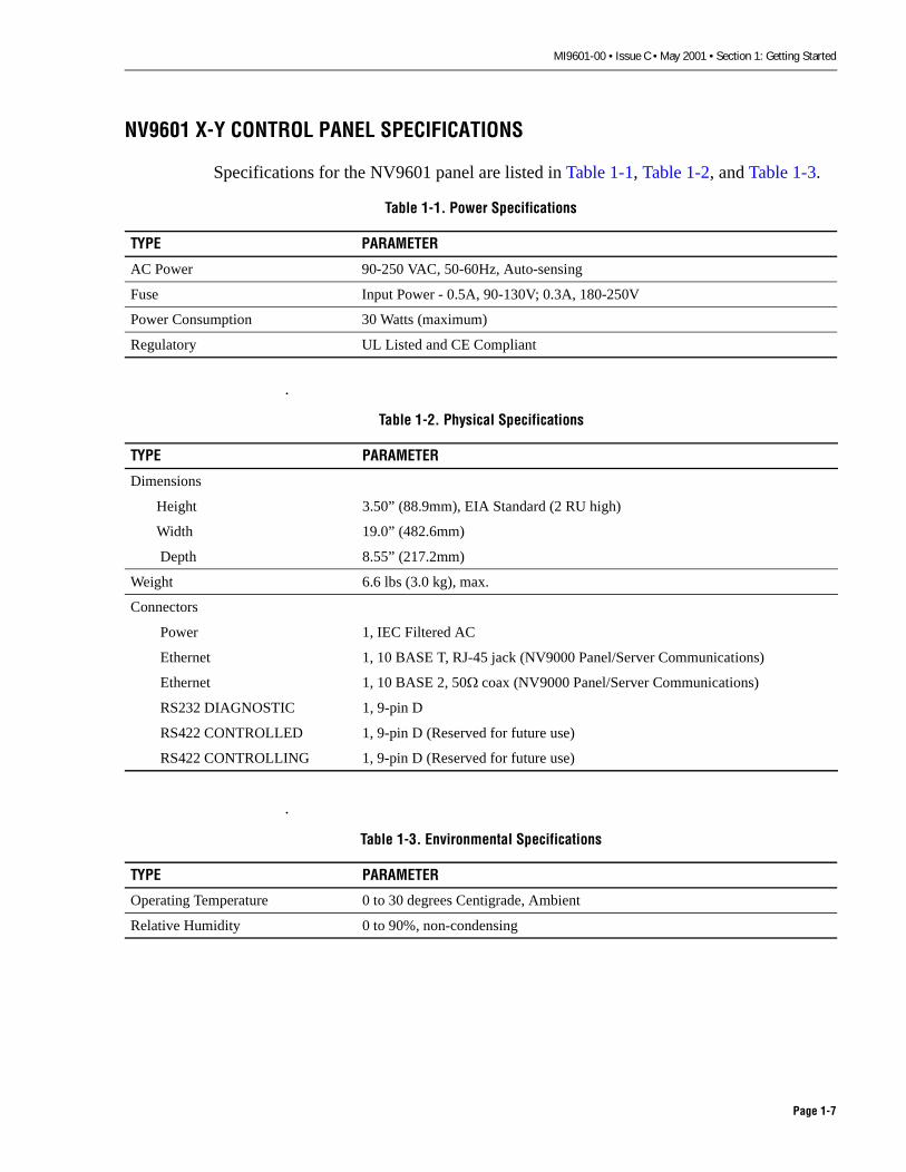
NV9601 X-Y CONTROL PANEL SPECIFICATIONS
Specifications for the NV9601 panel are listed in Table 1-1, Table 1-2, and Table 1-3.
�
�
Table 1-1. Power Specifications
TYPE PARAMETER
AC Power 90-250 VAC, 50-60Hz, Auto-sensing
Fuse Input Power - 0.5A, 90-130V; 0.3A, 180-250V
Power Consumption 30 Watts (maximum)
Regulatory UL Listed and CE Compliant
Table 1-2. Physical Specifications
TYPE PARAMETER
Dimensions
Height 3.50” (88.9mm), EIA Standard (2 RU high)
Width 19.0” (482.6mm)
Depth 8.55” (217.2mm)
Weight 6.6 lbs (3.0 kg), max.
Connectors
Power 1, IEC Filtered AC
Ethernet 1, 10 BASE T, RJ-45 jack (NV9000 Panel/Server Communications)
Ethernet 1, 10 BASE 2, 50 � coax (NV9000 Panel/Server Communications)
RS232 DIAGNOSTIC 1, 9-pin D
RS422 CONTROLLED 1, 9-pin D (Reserved for future use)
RS422 CONTROLLING 1, 9-pin D (Reserved for future use)
Table 1-3. Environmental Specifications
TYPE PARAMETER
Operating Temperature 0 to 30 degrees Centigrade, Ambient
Relative Humidity 0 to 90%, non-condensing
Page 1-7

MI9601-00 • Issue C • May 2001 • Section 1: Getting Started
Page 1-8

MI9601-00 • Issue C • May 2001 • Section 2: NV9601 Installation
SECTION 2: NV9601 InstallationThis section provides detailed installation instructions for the NV9601 X-Y Control Panel. We recommend that you start at the beginning of this section and work through it sequentially to complete the installation.
The following topics are covered:
�
CONFIGURING THE NV9601 PANEL. . . . . . . . . . . . . . . . . . . . . . . . . . . . . . . . . . . . . . . . . . . . . 2-2
INSTALLING KEY CAP LEGENDS. . . . . . . . . . . . . . . . . . . . . . . . . . . . . . . . . . . . . . . . . . . . . . . 2-3
Key Cap Legend Meanings . . . . . . . . . . . . . . . . . . . . . . . . . . . . . . . . . . . . . . . . . . . . . 2-5
Legend Installation Procedure. . . . . . . . . . . . . . . . . . . . . . . . . . . . . . . . . . . . . . . . . . . 2-6
PHYSICALLY INSTALLING THE NV9601 PANEL. . . . . . . . . . . . . . . . . . . . . . . . . . . . . . . . . . . . . 2-8
CONNECTING THE PANEL TO THE ENVY SERVER . . . . . . . . . . . . . . . . . . . . . . . . . . . . . . . . . . . 2-9
10 Base T Connection. . . . . . . . . . . . . . . . . . . . . . . . . . . . . . . . . . . . . . . . . . . . . . . . . 2-9
10 Base 2 Connection. . . . . . . . . . . . . . . . . . . . . . . . . . . . . . . . . . . . . . . . . . . . . . . . .2-10
APPLYING AC POWER TO THE PANEL . . . . . . . . . . . . . . . . . . . . . . . . . . . . . . . . . . . . . . . . . . 2-11
PANEL BOOT UP . . . . . . . . . . . . . . . . . . . . . . . . . . . . . . . . . . . . . . . . . . . . . . . . . . . . . . . . .2-12
SETTING THE PANEL ID AT THE PANEL . . . . . . . . . . . . . . . . . . . . . . . . . . . . . . . . . . . . . . . . . .2-13
Contents Page
Page 2-1

MI9601-00 • Issue C • May 2001 • Section 2: NV9601 Installation
CONFIGURING THE NV9601 PANEL
Before you physically install the panel and apply power, you must configure it using the NV9000 Configuration Manager and the NV9000 NV9601 Configuration Editor on a Windows-based PC. Without the proper configuration, the panel is inoperable. Refer to the NV9000 Configuration Manager User Guide for details about how to configure the NV9601 Control Panel. The tasks you need to do include the following:
• Create an NV9601 configuration file and identify the path to the file using the NV9601 Configuration Editor. This includes button function assignments and panel operating mode selections.
• Create the Panel Name and Panel ID for this panel in the NV9000 Configuration Manager.
• Enter the user name and NV9601 configuration file path for this panel into the NV9000 Configuration Manager.
Page 2-2

MI9601-00 • Issue C • May 2001 • Section 2: NV9601 Installation
INSTALLING KEY CAP LEGENDS
NOTE: NVISION recommends that the initial installation of the key cap legends be doneprior to installing the NV9601 into the equipment rack. In most cases, this makes handling and installation easier.
You received the NV9601 X-Y Control Panel with all key caps blank, along with a mylar sheet of standard key cap legends (see Figure 2-1). These key cap legends are intended to be installed in the Function button positions and numeric keypad positions. (Refer to “NV9601 Front Panel Description” in Section 1 for location if needed.) The following pages explain the purpose of each button function and associated legend, and how to install the legends.
Note that not all legends are used with the NV9601 and not all functions are available at the same time. The applicable buttons are programmed through the NV9601 Configuration Editor.
Because the placement of the legends is determined by the configuration you create in the NV9601 Configuration Editor, we recommend you copy the template, Figure 2-4, later in this section and use it to write down the button assignments you make in the configuration. Then you can refer to your notes on the template when you install the legends into the panel buttons.
Figure 2-1. Supplied Key Cap Legends
������
����
��
����
����
������
�������
��������
�������
���������
�������
�����
������
�����
��������
��
���������� ���� ����
���� ���� ���������� ���� ���
�������
!" # $
%&' ( )
$" ! #
*��� ����(& ) %
+��,
Page 2-3

MI9601-00 • Issue C • May 2001 • Section 2: NV9601 Installation
Note that except for the dedicated buttons shown in Figure 2-2 and identified below, install the key cap legends on key caps as defined in the NV9601 Configuration Editor. For more information about the meaning of each legend, see the list of legends on the following page..
Figure 2-2. Dedicated buttons
NVISION does not provide legends for the following key groups. This allows users to configure the buttons to meet their needs and to make and install custom legends. (For a template and instructions to make your own custom button legends, see the NVISION ftp site at ftp://www.nvision1.com/envy/BlnkLgnd1.doc.)
Category Keys: Twenty keys used for category entry during source anddestination entry. Note that except for the numeric keypad, category keys can be programmed as Quick Source or function keys.
� The [Take] button.
� The eight Line Selection buttons ([1]-[8]).
� The [Page Up] and [Page Dn] buttons.
� Numeric positions [0]-[9] reserved for the standard formation key pad. Note that the numbers are in the bottom third of the key cap, leaving room for custom legends in the top two thirds.
� Note: The remaining key caps in Figure 2-2. are only examples.
�������� ������
���� �
�����
����
��������
�� ����
����
���
� � � ! � " #
$�%� ����% &�'�%�
��
����� ����� � �� ��� � � � � � � � �� �� �
��� � � � � � ����� ����� ��� � � ������ ����� ��� � � ������ ����� ��� ��� ����� ����� � � � � � �
� � � � � � � �
�� � � � � � � � ��� � � �� � � � � � � �� � � � � � � � ��� � � � �� � � � � � � � �
�
����
���! !! �
" �$()�
��*
�
+��*
����
"
,����� -�.������
�
*/�
01
�%��
���
23��
#
���3��
�
�4�
�/��
��
-2��
���*
!
���/�����
�
+��/+����
��
����
��%�
�
�%�
�
�/
��
����
+�$���
&�5�
�5����
�%�
��5
$����5
,���5
+��3
� � �������� �
�������
���� �
������������������������������������������������������
�� ��������������
�� �������� �������� �������� ������
����������������
��������������� ������ �!��"�#��#�� $���������%��
$(��6�
� � �
Page 2-4

MI9601-00 • Issue C • May 2001 • Section 2: NV9601 Installation
Key Cap Legend Meanings
Currently available key cap legends for the NV9601 X-Y Control Panel are listed and briefly described below. Some legends supplied are used with other panels and are not used with the NV9601. See "NV9601 Button Descriptions" on page 3-5 for more detailed information about button functions.
LEGEND(S) PURPOSE
0-9(Category)
These ten buttons form a traditional key pad. Part of the category buttons, they are used for source and destination selection.
1-8(Selection)
These eight buttons select lines on the display which may be destinations, levels, menu items, or salvos.
Clear Clears the current entry on the display.
Clear Prst Clears all presets and the current source selection, and reselects all levels in X-Y mode or deselects all destinations in Multi-Destination mode.
Def State Returns the panel to a system administrator defined default, or home state.
Dest Puts the panel into destination selection mode.
Free Src Loads defined free sources into preset fields.
Hold Holds the selected breakaway levels in X-Y mode or multiple destinations in Multi-Destination mode.
Info Provides additional information.
Lock Locks or (force) Releases either a source in the status column or the currently selected destination(s), depending on the Control Panel selection mode.
Lvl Map or Level Allows mapping of virtual levels in X-Y mode only.
Menu Programs panel behavior at the panel.
Page Dn With Page Up, scrolls through the different pages of levels (in X-Y mode), desti-nations (in Multi-Destination mode), or salvos (in Salvo Creation/Execution mode).
Page Up With Page Dn, scrolls through the different pages of levels (in X-Y mode), desti-nations (in Multi-Destination mode), or salvos (in Salvo Creation/Execution mode).
Prst Rel Releases the current source preset(s).
Prev Src Loads previously switched sources into preset fields.
Prot Protects or (force) Releases either a source in the status column or the currently selected destinations, depending on the Control Panel selection mode.
Salvo Accesses the salvo selection function.
Save Prst Saves the current presets (devices and level mappings) in X-Y mode. It has no effect in Multi-Destination mode.
Scrl Allows scrolling through sources and destinations, depending on the Control Panel selection mode.
Src Puts the panel into source selection mode.
Take Switches preset source(s) to selected destination(s).
XY/Mult Switches the panel between X-Y and Multi-Destination modes.
Page 2-5

MI9601-00 • Issue C • May 2001 • Section 2: NV9601 Installation
Legend Installation Procedure
Install the key cap legends into the button caps as follows. No tools are required. Installing the legends with the panel on a table or work bench is easier than trying to do it with the panel in an equipment rack.
1. Decide which of the supplied legends you want to use and on which buttons you want to install them (other than the dedicated ones shown in Figure 2-2). Note the chosen legend locations using the template on the next page (Figure 2-4).
2. Place the mylar legends and the legend location template on a flat surface near your work area where you can read them.
3. Position the NV9601 front panel for easy access to the key caps and legends.
4. Remove the key caps from the front panel by gently prying up on the side of each cap with your fingers. Put the key caps on the work surface.
5. Place a legend into each key cap and assemble the key caps onto the push buttons in the panel as shown in Figure 2-3. Be sure to place the correct legends on dedicated push buttons, such as the Take button and the numerical keypad buttons, as shown in Figure 2-4.
Figure 2-3. Key Cap Legend Installation
Caution: Be sure to adequately support the Control Panel while installing the key cap legends so as to prevent damage to the panel or its connectors.
� Note: Ensure the legend is placed so as to be legible once the key cap is installed. Somebuttons may have two legends, such as numeric keypad buttons that also serve as functionor category buttons.
ClearKeyCap
Legend
PushButton
Page 2-6

MI9601-00 • Issue C • May 2001 • Section 2: NV9601 Installation
Figure 2-4. NV9601 Key Cap Legend Location Template
�������������
�������
������������������������ �������
����
������������
����
��
����
�
�
��
�
��
�
� !
"
��
��
��
#�$�
Page 2-7

MI9601-00 • Issue C • May 2001 • Section 2: NV9601 Installation
PHYSICALLY INSTALLING THE NV9601 PANEL
The NV9601 Panel was designed for installation in a standard 19-inch electronic equipment rack as shown in Figure 2-5. It may also be placed on a flat, level surface such as a desk or table. To install the Control Panel:
1. Determine where you want the NV9601. Note the following:
The panel must be within six feet of an AC power source.
It must also be within easy reach of the NV9000 Server (10 Base 2) or Ethernet Hub (10 Base T).
NV9601 panels can be stacked on top of each other without cooling space above or below. However, do not place the panel on top of any equipment that generates a lot of heat.
2. If you install the panel in a 19-inch (483mm) equipment rack, secure the panel in the rack using four rack screws (not supplied) as shown in Figure 2-5. If you prefer, you can use nylon washers (not supplied) with the screws to protect the panel from being marred.
Figure 2-5. NV9601 Equipment Rack Installation
NVision2ision2 NV9601
Clear
Info
DefaultState
Take Chop
Salvo
Menu
X-YMulti
1 2 3 4 5 6 7 8
Preset Status Lev/Dest
PageUp
VTR
1
HDDR
4
Ctrl
7
FrStor AuxSrStor
0
Disk
2
SDDR
5
Edit
8
Studio
9
SDCamSDMon
6
HDCamHDMon
CGenXmit
Test
3
Cam
SD
Remt
Key
TCine
HD
Sat
Ctrl
Net
AESX
Mstr
VIS
Prot
Lock
Scroll
Dest
Src
HoldPageDown
PrevSrc
FreeSrc
VTR-02- - - - - - - -VTR-02VTR-02VTR-02VTR-02- - - - - - - -- - - - - - - -
HDVideoSDVideoAES 1/2AES 3/4ControlTimeCodeAnVideoAnAudio
L* VTR-01 - - - - - - - -L* VTR-01L* VTR-01L VTR-01L VTR-01 - - - - - - - - - - - - - - - -
X - YDestMonitor 1
VTR_ _ _2
Page 1
Page 2-8
MI9601-00 • Issue C • May 2001 • Section 2: NV9601 Installation
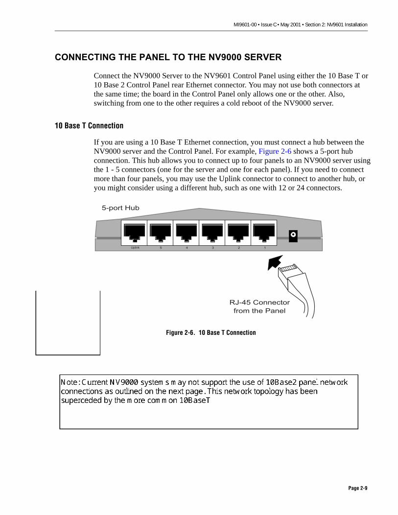
CONNECTING THE PANEL TO THE NV9000 SERVER
Connect the NV9000 Server to the NV9601 Control Panel using either the 10 Base T or 10 Base 2 Control Panel rear Ethernet connector. You may not use both connectors at the same time; the board in the Control Panel only allows one or the other. Also, switching from one to the other requires a cold reboot of the NV9000 server.
10 Base T Connection
If you are using a 10 Base T Ethernet connection, you must connect a hub between the NV9000 server and the Control Panel. For example, Figure 2-6 shows a 5-port hub connection. This hub allows you to connect up to four panels to an NV9000 server using the 1 - 5 connectors (one for the server and one for each panel). If you need to connect more than four panels, you may use the Uplink connector to connect to another hub, or you might consider using a different hub, such as one with 12 or 24 connectors.
Figure 2-6. 10 Base T Connection
� � � � �
���� � �
������
����� ������
�� ��� �����
Page 2-9
WARDG
Note: Current NV9000 systems may not support the use of 10Base2 panel network connections as outlined on the next page. This network topology has been superceded by the more common 10BaseT
WARDG
MI9601-00 • Issue C • May 2001 • Section 2: NV9601 Installation
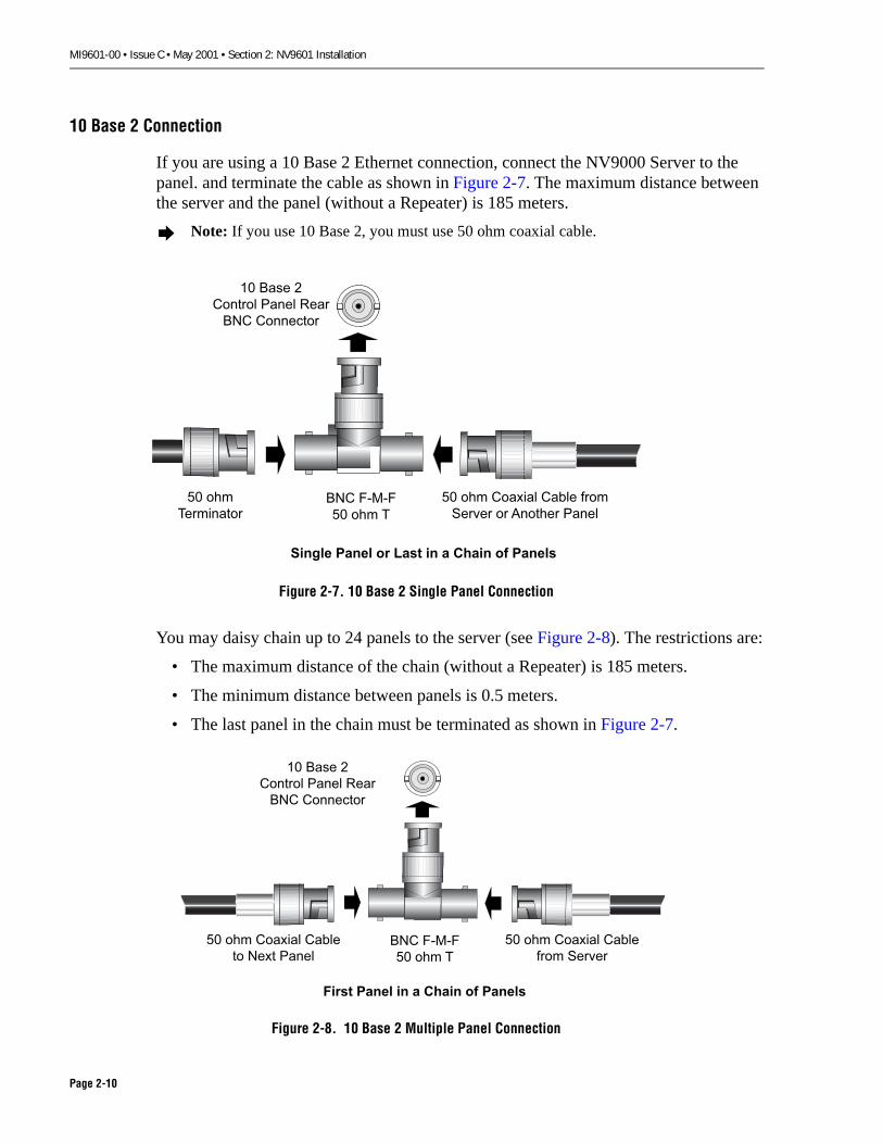
10 Base 2 Connection
If you are using a 10 Base 2 Ethernet connection, connect the NV9000 Server to the panel. and terminate the cable as shown in Figure 2-7. The maximum distance between the server and the panel (without a Repeater) is 185 meters.
Figure 2-7. 10 Base 2 Single Panel Connection
You may daisy chain up to 24 panels to the server (see Figure 2-8). The restrictions are:
• The maximum distance of the chain (without a Repeater) is 185 meters.
• The minimum distance between panels is 0.5 meters.
• The last panel in the chain must be terminated as shown in Figure 2-7.
Figure 2-8. 10 Base 2 Multiple Panel Connection
� Note: If you use 10 Base 2, you must use 50 ohm coaxial cable.
�� ���
����� �
�� ��� ������ ����� ���
���� � ��� �� �����
������ ���� � � � �� ���� � ����
��� �����
�� ��� �
�� ���� �
��� �� ����� ���
��� ����� �
����� ��� � � � �� �� ����
�� ��� ����� ����
���� � �� �
�� ��� ����� ����
�� � � ��� �
��� �����
�� ��� �
�� ��� �
������� ��� � � ��
��� ���� ����
Page 2-10

MI9601-00 • Issue C • May 2001 • Section 2: NV9601 Installation
APPLYING AC POWER TO THE PANEL
Connect the supplied power cord from the Control Panel to an AC power source of 90-130 or 180-250 VAC, 50-60 Hz (Figure 2-9). The power supply is auto-ranging, so it will automatically adjust to any AC power within the stated range. For power cord wiring, see the diagrams preceding the Table of Contents in this manual under the heading “NORTH AMERICAN POWER SUPPLY CORDS” or “INTERNATIONAL POWER SUPPLY CORDS”.
Figure 2-9. AC Power Connection
� Note: There is no On/Off switch on the NV9601 and therefore, power is applied to thepanel when the power cord is connected.
90-130 or 180-250 VAC, 50-60 Hz, Auto-Sensing
Fuse Holder,1 fuse plus a spare,
1 Amp, 250 V
Page 2-11

MI9601-00 • Issue C • May 2001 • Section 2: NV9601 Installation
PANEL BOOT UP
When power is applied, the panel begins to boot up. As it does so, it displays a series of messages. If the panel has already been configured and assigned a Panel ID, the panel assumes the default state within a few seconds, provided the NV9000 software is currently running. If the Panel ID or configuration file is incorrect, or if the panel is disconnected from the server, an error message will continue to display until the Panel ID is set or the configuration file is corrected.
The above screen indicates that the panel is trying to acquire an IP address. The second line shows the Panel ID.
The above screen indicates that the panel is trying to communicate with the NV9000 Server. If all is OK, the Control Panel boots up in the default state; otherwise an error message appears.
� Note: If the above sequence of screen displays do not occur, refer to “Troubleshooting” inSection 4.
��� ��
���� �
��� ���
��� ��
Page 2-12

MI9601-00 • Issue C • May 2001 • Section 2: NV9601 Installation
SETTING THE PANEL ID AT THE PANEL
The final step to placing your NV9601 X-Y Control Panel in service is loading its configuration from the NV9000 server. This is done by setting its Panel ID to the Panel ID assigned in the Configuration Manager. To set the Panel ID at the NV9601 Panel, use the following procedure:
1. If you have not already done so, connect the power cord to the panel and ensure that the Ethernet cable is disconnected.
2. As the panel goes through boot up (see “Applying Power to the Panel), wait until [Page Up] lights and then press [Page Up].
The Firmware Menu shown below appears on the display. Below the display, line selection buttons [1] - [3] and [8] go On (light). Note that you must press [8] to exit this menu.
3. Press line selection button [1] to select Firmware Menu item Panel ID, which allows you to assign an ID at the panel. The display shown below appears and the keypad buttons and line selection buttons [7] and [8] go On (light). Note that the Panel ID can be changed in this menu even if the Panel ID has been configured as read-only in the NV9601 Configuration Editor.
4. Use the numeric keypad to enter a new Panel ID. Press [8] to save the new ID or [7] to cancel the operation. Pressing [7] returns you to the Firmware Menu. If you press [8], when the Ethernet cable is reconnected and the NV9000 software is running, the Panel immediately assumes the configuration assigned in the Configuration Manager.
This completes basic installation of the NV9601 Control Panel. For information about how to operate the panel, see Section 3, “NV9601 Operation” in this manual. For information about panel configuration, see the NV9000 Configuration Manager User Guide.
�������� �� ��� ��������������
����
�������� ����� ��
��������� �� ����� ��������
��
���� ����
��� ��
Page 2-13

MI9601-00 • Issue C • May 2001 • Section 2: NV9601 Installation
Page 2-14

MI9601-00 • Issue B • September 2000 • Section 3: NV9601 Operation
Section 3: NV9601 OperationThis section explains NV9601 X-Y Control Panel operation. These topics are covered:�
CONVENTIONS USED IN THIS SECTION . . . . . . . . . . . . . . . . . . . . . . . . . . . . . . . . . . . . . . . . . . 3-2
NV9601 OPERATIONAL QUICK REFERENCE . . . . . . . . . . . . . . . . . . . . . . . . . . . . . . . . . . . . . . . 3-2
NV9601 GENERAL OPERATING INFORMATION . . . . . . . . . . . . . . . . . . . . . . . . . . . . . . . . . . . . . 3-4
Numeric Entry General Information . . . . . . . . . . . . . . . . . . . . . . . . . . . . . . . . . . . . . . . 3-4
NV9601 BUTTON DESCRIPTIONS . . . . . . . . . . . . . . . . . . . . . . . . . . . . . . . . . . . . . . . . . . . . . . 3-5
NV9601 MENU DESCRIPTION . . . . . . . . . . . . . . . . . . . . . . . . . . . . . . . . . . . . . . . . . . . . . . . . 3-8
Software . . . . . . . . . . . . . . . . . . . . . . . . . . . . . . . . . . . . . . . . . . . . . . . . . . . . . . . . . 3-8User . . . . . . . . . . . . . . . . . . . . . . . . . . . . . . . . . . . . . . . . . . . . . . . . . . . . . . . . . . . . 3-8Panel. . . . . . . . . . . . . . . . . . . . . . . . . . . . . . . . . . . . . . . . . . . . . . . . . . . . . . . . . . . . 3-9Illumination . . . . . . . . . . . . . . . . . . . . . . . . . . . . . . . . . . . . . . . . . . . . . . . . . . . . . . 3-10Button Illumination . . . . . . . . . . . . . . . . . . . . . . . . . . . . . . . . . . . . . . . . . . . . . . . . . 3-10Salvo . . . . . . . . . . . . . . . . . . . . . . . . . . . . . . . . . . . . . . . . . . . . . . . . . . . . . . . . . . . 3-11Force Release. . . . . . . . . . . . . . . . . . . . . . . . . . . . . . . . . . . . . . . . . . . . . . . . . . . . . 3-11Exit . . . . . . . . . . . . . . . . . . . . . . . . . . . . . . . . . . . . . . . . . . . . . . . . . . . . . . . . . . . . 3-12
NV9601 SALVO DESCRIPTION . . . . . . . . . . . . . . . . . . . . . . . . . . . . . . . . . . . . . . . . . . . . . . . 3-12
Create, Save, and Clear a Local Salvo . . . . . . . . . . . . . . . . . . . . . . . . . . . . . . . . . . . . 3-12
NV9601 OPERATING PROCEDURES . . . . . . . . . . . . . . . . . . . . . . . . . . . . . . . . . . . . . . . . . . . 3-16
NV9601 X-Y Mode of Operation . . . . . . . . . . . . . . . . . . . . . . . . . . . . . . . . . . . . . . . . . 3-16
Display Illumination . . . . . . . . . . . . . . . . . . . . . . . . . . . . . . . . . . . . . . . . . . 3-11X-Y Mode Display Description. . . . . . . . . . . . . . . . . . . . . . . . . . . . . . . . . . . . 3-17Performing a Take (X-Y Mode) . . . . . . . . . . . . . . . . . . . . . . . . . . . . . . . . . . . 3-19Selecting Levels (X-Y Mode) . . . . . . . . . . . . . . . . . . . . . . . . . . . . . . . . . . . . 3-20Holding Levels (X-Y Mode). . . . . . . . . . . . . . . . . . . . . . . . . . . . . . . . . . . . . . 3-20Mapping Levels . . . . . . . . . . . . . . . . . . . . . . . . . . . . . . . . . . . . . . . . . . . . . 3-20Saving Presets (X-Y Mode). . . . . . . . . . . . . . . . . . . . . . . . . . . . . . . . . . . . . . 3-21Performing a Single Level (Breakaway) Switch (X-Y Mode). . . . . . . . . . . . . . . . 3-22Performing Multiple Source Breakaways (X-Y Mode) . . . . . . . . . . . . . . . . . . . . 3-23
Multi-Destination Mode of Operation . . . . . . . . . . . . . . . . . . . . . . . . . . . . . . . . . . . . . 3-24
Multi-Destination Mode Display Description . . . . . . . . . . . . . . . . . . . . . . . . . . 3-25Performing a Take (Multi-Destination Mode). . . . . . . . . . . . . . . . . . . . . . . . . . 3-26Performing a One Time Salvo (Multi-Destination Mode) . . . . . . . . . . . . . . . . . . 3-27Performing a Gang or Dub Switch (Multi-Destination Mode) . . . . . . . . . . . . . . . 3-28Programming a Destination Position . . . . . . . . . . . . . . . . . . . . . . . . . . . . . . . 3-29Clearing a Programmed Destination Position . . . . . . . . . . . . . . . . . . . . . . . . . 3-30
Contents Page
Page 3-1
MI9601-00 • Issue B • September 2000 • Section 3: NV9601 Operation
CONVENTIONS USED IN THIS SECTION
The following typographical conventions are followed in this section:
• Buttons are bolded in brackets: [Shift].
• Buttons whose names may vary are in parentheses: [(numeric)].
• Buttons to be pressed sequentially are separated by a comma: [Submit], [Reset].
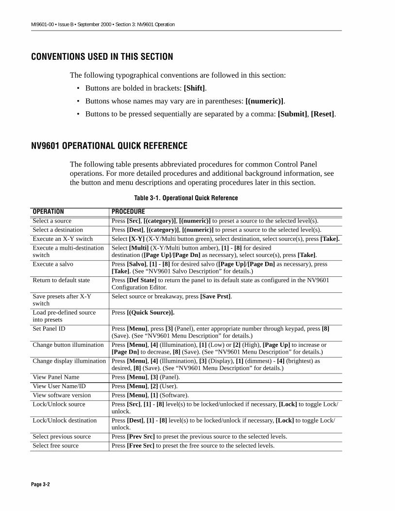
NV9601 OPERATIONAL QUICK REFERENCE
The following table presents abbreviated procedures for common Control Panel operations. For more detailed procedures and additional background information, see the button and menu descriptions and operating procedures later in this section.
Table 3-1. Operational Quick Reference
OPERATION PROCEDURESelect a source Press [Src], [(category)], [(numeric)] to preset a source to the selected level(s).
Select a destination Press [Dest], [(category)], [(numeric)] to preset a source to the selected level(s).
Execute an X-Y switch Select [X-Y] (X-Y/Multi button green), select destination, select source(s), press [Take].Execute a multi-destination switch
Select [Multi] (X-Y/Multi button amber), [1] - [8] for desireddestination ([Page Up]/[Page Dn] as necessary), select source(s), press [Take].
Execute a salvo Press [Salvo], [1] - [8] for desired salvo ([Page Up]/[Page Dn] as necessary), press [Take]. (See “NV9601 Salvo Description” for details.)
Return to default state Press [Def State] to return the panel to its default state as configured in the NV9601 Configuration Editor.
Save presets after X-Y switch
Select source or breakaway, press [Save Prst].
Load pre-defined source into presets
Press [(Quick Source)].
Set Panel ID Press [Menu], press [3] (Panel), enter appropriate number through keypad, press [8] (Save). (See “NV9601 Menu Description” for details.)
Change button illumination Press [Menu], [4] (Illumination), [1] (Low) or [2] (High), [Page Up] to increase or [Page Dn] to decrease, [8] (Save). (See “NV9601 Menu Description” for details.)
Change display illumination Press [Menu], [4] (Illumination), [3] (Display), [1] (dimmest) - [4] (brightest) as desired, [8] (Save). (See “NV9601 Menu Description” for details.)
View Panel Name Press [Menu], [3] (Panel).
View User Name/ID Press [Menu], [2] (User).
View software version Press [Menu], [1] (Software).
Lock/Unlock source Press [Src], [1] - [8] level(s) to be locked/unlocked if necessary, [Lock] to toggle Lock/unlock.
Lock/Unlock destination Press [Dest], [1] - [8] level(s) to be locked/unlock if necessary, [Lock] to toggle Lock/unlock.
Select previous source Press [Prev Src] to preset the previous source to the selected levels.
Select free source Press [Free Src] to preset the free source to the selected levels.
Page 3-2

MI9601-00 • Issue B • September 2000 • Section 3: NV9601 Operation
Protect/Unprotect source Press [Src], [1] - [8] level(s) to be locked/unlocked if necessary, [Prot] to toggle Protect/unprotect.
Protect/Unprotect destina-tion
Press [Dest], [1] - [8] level(s) to be locked/unlock if necessary, [Prot] to toggle Protect/unprotect.
Hold levels after X-Y switch
Select [1] - [8] for desired level(s) to hold, press [Hold].
Map Levels Press [Lvl Map] or [Level], select desired source level, select desired destination level. This maps selected source level to selected destination level.
X-Y Breakaway Switch, single source, single level
Select destination, select [1] - [8] for desired level, select source, press [Take].
X-Y Breakaway Switch, single source, multiple lev-els
Select destination, select source, select [1] - [8] to clear preset forundesired level(s), press [Take].
X-Y Breakaway Switch, multiple sources
Select destination, select [1] - [8] for desired level, select source, press [1] - [8] to toggle off previous levels, repeat for all sources, select source, press [Take].
One time salvo, multi-desti-nation mode
Select [Multi] (X-Y/Multi button amber), select destination, select source(s), repeat for all desired sources/destinations, press [Take].
Gang (Dub) switch, multi-destination mode
Select [Multi] (X-Y/Multi button amber), press [Hold], press[1] - [8] to deselect and select destination as desired, select source, press [Take].
Hold destinations after multi-destination switch
Select [Multi] (X-Y/Multi button amber), press [Hold], press[1] - [8] to deselect and select destination as desired.
Table 3-1. Operational Quick Reference
OPERATION PROCEDURE
Page 3-3

MI9601-00 • Issue B • September 2000 • Section 3: NV9601 Operation
NV9601 GENERAL OPERATING INFORMATION
The following pages provide general information about panel behavior.
Numeric Entry General Information
When you select a menu that requires numeric entries, the ten key pad buttons light. These buttons are labeled 0-9 and may be used to enter numbers. Digits enter the display on the right and move to the left as more numbers are entered. If you enter more than eight digits, numbers at the left end of the display are discarded. For example, if you enter 5 - 5 - 5 - 5 - 0 - 0 - 1 - 3 - 6, the first 5 that you entered is discarded because the number of digits you entered exceeds 8.
Page 3-4

MI9601-00 • Issue B • September 2000 • Section 3: NV9601 Operation
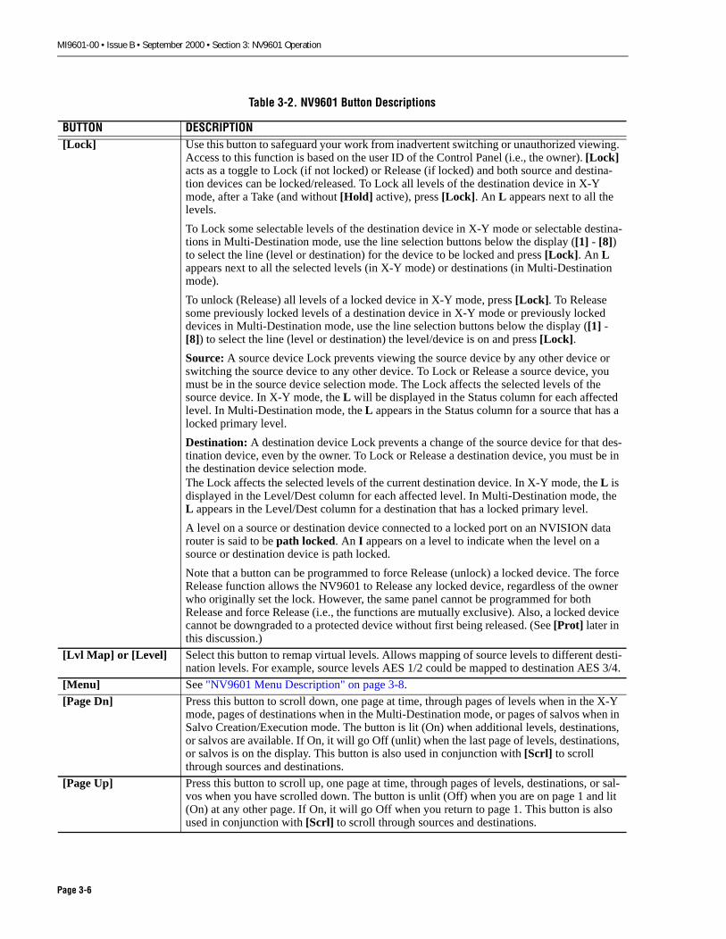
NV9601 BUTTON DESCRIPTIONS
The following describes the functions of the buttons in the NV9601 Panel.
Table 3-2. NV9601 Button Descriptions
BUTTON DESCRIPTION[Clear] Use this button to clear the current source or destination device selection while in the selec-
tion process. For example, in the highlighted portion of the illustration below, while in the process of selecting a device (VTR 3) you inadvertently press [2] instead of [3]. Pressing [Clear] erases VTR 2 and you can then begin the selection process again.
[Clear Prst] Press this button to remove the entries in the Preset column of the panel display and the cur-rent selection entry in the first column. All levels are reselected in X-Y mode or all destina-tions are deselected in Multi-Destination mode.
[Def State] Press this button to return the panel to a pre-defined default state defined in the NV9601 Configuration Editor.
[Dest] Press this button to enter the Destination Selection mode. When pressed, all destination related buttons become available (dim amber), some buttons go from green to amber, and some buttons stay green.
[Free Src] In X-Y mode, press this button to load the free source into the preset field of the current des-tination. When [Take] is pressed, selected levels of the free source are taken to the level set of the destination, and any level mappings are removed. In Multi-Destination mode, press this button to load defined free source(s) into the preset fields of the selected destination(s). The free source is defined in the Configuration Manager.
[Hold] Use this button to retain selection of one or more levels or destinations after a Take, instead of returning to selection of all levels or of no destinations. To use, press [Hold] and then, below the display, press the [1] through [8] line selection buttons for the items you want to retain. Press [Hold] again to turn Hold Off.
[Info] Press this button to show additional information on the display. An example of an informa-tion message is shown below. To return to the previous selection display, press [Info] again.
VTR-02- - - - - - - -VTR-02VTR-02VTR-02VTR-02- - - - - - - -- - - - - - - -
L+ VTR-01 - - - - - - - -L+ VTR-01L+ VTR-01L* VTR-01L* VTR-01 - - - - - - - - - - - - - - - -
HDVideoSDVideoAES 1/2AES 3/4TimeCodeC o n t r o lAnV ideoAnAudio
X - YDestMonitor 1
Page 1
VTR_ _ _2
T h e C O N T R O L l e v e l o n V T R - 0 1 i s i nu s e .
Page 3-5
MI9601-00 • Issue B • September 2000 • Section 3: NV9601 Operation
[Lock] Use this button to safeguard your work from inadvertent switching or unauthorized viewing. Access to this function is based on the user ID of the Control Panel (i.e., the owner). [Lock] acts as a toggle to Lock (if not locked) or Release (if locked) and both source and destina-tion devices can be locked/released. To Lock all levels of the destination device in X-Y mode, after a Take (and without [Hold] active), press [Lock]. An L appears next to all the levels.
To Lock some selectable levels of the destination device in X-Y mode or selectable destina-tions in Multi-Destination mode, use the line selection buttons below the display ([1] - [8]) to select the line (level or destination) for the device to be locked and press [Lock]. An L appears next to all the selected levels (in X-Y mode) or destinations (in Multi-Destination mode).
To unlock (Release) all levels of a locked device in X-Y mode, press [Lock]. To Release some previously locked levels of a destination device in X-Y mode or previously locked devices in Multi-Destination mode, use the line selection buttons below the display ([1] - [8]) to select the line (level or destination) the level/device is on and press [Lock].
Source: A source device Lock prevents viewing the source device by any other device or switching the source device to any other device. To Lock or Release a source device, you must be in the source device selection mode. The Lock affects the selected levels of the source device. In X-Y mode, the L will be displayed in the Status column for each affected level. In Multi-Destination mode, the L appears in the Status column for a source that has a locked primary level.
Destination: A destination device Lock prevents a change of the source device for that des-tination device, even by the owner. To Lock or Release a destination device, you must be in the destination device selection mode.The Lock affects the selected levels of the current destination device. In X-Y mode, the L is displayed in the Level/Dest column for each affected level. In Multi-Destination mode, the L appears in the Level/Dest column for a destination that has a locked primary level.
A level on a source or destination device connected to a locked port on an NVISION data router is said to be path locked. An I appears on a level to indicate when the level on a source or destination device is path locked.
Note that a button can be programmed to force Release (unlock) a locked device. The force Release function allows the NV9601 to Release any locked device, regardless of the owner who originally set the lock. However, the same panel cannot be programmed for both Release and force Release (i.e., the functions are mutually exclusive). Also, a locked device cannot be downgraded to a protected device without first being released. (See [Prot] later in this discussion.)
[Lvl Map] or [Level] Select this button to remap virtual levels. Allows mapping of source levels to different desti-nation levels. For example, source levels AES 1/2 could be mapped to destination AES 3/4.
[Menu] See "NV9601 Menu Description" on page 3-8.
[Page Dn] Press this button to scroll down, one page at time, through pages of levels when in the X-Y mode, pages of destinations when in the Multi-Destination mode, or pages of salvos when in Salvo Creation/Execution mode. The button is lit (On) when additional levels, destinations, or salvos are available. If On, it will go Off (unlit) when the last page of levels, destinations, or salvos is on the display. This button is also used in conjunction with [Scrl] to scroll through sources and destinations.
[Page Up] Press this button to scroll up, one page at time, through pages of levels, destinations, or sal-vos when you have scrolled down. The button is unlit (Off) when you are on page 1 and lit (On) at any other page. If On, it will go Off when you return to page 1. This button is also used in conjunction with [Scrl] to scroll through sources and destinations.
Table 3-2. NV9601 Button Descriptions
BUTTON DESCRIPTION
Page 3-6

MI9601-00 • Issue B • September 2000 • Section 3: NV9601 Operation
[Prev Src] Press this button to load the previously switched source for the current destination(s) into the preset field(s) of the current destination(s). This is useful if you need to repeatedly tog-gle between sources or recover from a mistaken source selection. Note that the level map-pings of the previous source are used. Also note that the previous source may not be the last source switched by this panel; it may have been switched at another panel.
[Prot] Use this button to safeguard your work from inadvertent switching or unauthorized viewing. Access to this function is based on the user ID of the Control Panel (i.e., the owner). [Prot] acts as a toggle to Protect (if not protected) or Release (if protected) and both source and destination devices can be protected/released.
To Protect all levels of the destination device in X-Y mode, after a Take (and without [Hold] active), press [Prot]. On the display, a P appears next to all selected levels.
To Protect some levels of the destination device in X-Y mode or destinations in Multi-Des-tination mode, use the line selection buttons below the display ([1] - [8]) to select the line (level or destination) for the device to be protected and press [Prot]. A P appears by selected levels (in X-Y mode) or destinations (in Multi-Destination mode).
To unprotect (Release) all levels of a protected device in X-Y mode, press [Prot]. To Release previously protected levels of a destination device in X-Y mode or previously pro-tected destinations in Multi-Destination mode, use the line selection buttons below the dis-play ([1] - [8]) to select the line (level or destination) the level/device is on and press [Prot].
Source: A source device Protect allows only the owner to switch that device to another des-tination device. To Protect or Release a source device, you must be in the source device selection mode. The Protect affects the selected levels of the source device. In X-Y mode, the P is displayed in the Status column for each affected level. In Multi-Destination mode, the P appears in the Status column for a source that has a protected primary level.
Destination: A destination device Protect allows only the owner to change the source device routed to that destination device. To Protect or Release a destination device, you must be in the destination device selection mode. The Protect affects the selected levels of the current destination device. In X-Y mode, the P is displayed in the Level/Dest column for each affected level. In Multi-Destination mode, the P appears in the Level/Dest column for a destination that has a protected primary level.
A level on a source or destination device connected to a protected port is said to be path protected. An I appears on a level to indicate when the level on a source or destination device is path protected.
Note that a button can be programmed to force Release (unprotect) a protected device. The force Release function allows the NV9601 to Release a protected device, regardless of the owner who originally set the Protect. However, the same panel cannot be programmed for both Release and force Release (i.e., the functions are mutually exclusive). A protected device can be upgraded to a locked device without first being released. (See [Lock] button.)
[Salvo] See "NV9601 Salvo Description" on page 3-12.
[Save Prst] Press this button to save the preset source devices and level mappings currently shown in the Preset column. (This function is not available in Multi-Destination mode.)
[Scrl] Use this button to scroll through the device list for a selected category.
[Src] Press this button to enter the Source Selection mode. When pressed, all source related but-tons go On (light), some buttons go from amber to green, and some buttons stay amber.
[Take] Press this button to perform the switch from the currently selected source device(s) to the currently selected destination device(s). The switch data goes from the NV9601, through the NV9000 Server, to the selected Router(s).
[XY/Mult] Press this button to select either X-Y mode of operation or Multi-Destination mode of oper-ation. See "NV9601 Operating Procedures" on page 3-16 for more information.
Table 3-2. NV9601 Button Descriptions
BUTTON DESCRIPTION
Page 3-7

MI9601-00 • Issue B • September 2000 • Section 3: NV9601 Operation
NV9601 MENU DESCRIPTION
The display menus are explained on the following pages. When [Menu] is pressed, the display shown below appears and buttons [1] through [6] and [8] light. Buttons [1] - [6] select applicable display Menu items, and button [8] exits the Menu and returns you to the most recent selection display.
Software
To view the software version, press [1] from the Menu display. Below the display, [8] remains lit and [1] - [5] go Off (unlit). An example of the Software display is shown below. Press [8] (Exit) to return to the Menu or press [Menu] to return to the most recent selection display.
User
To view the User Name and User ID of this NV9601 Control Panel, press [2] from the Menu display. Below is an example of the User display. Press [8] (Exit) to return to the Menu display or press [Menu] to return to the most recent selection display.
Menu Software 1User 2Panel 3Illumination 4Salvo 5Force Release 6
Exit 8
MenuSoftware Server SVxxxx-xxxxxx 2
Panel Boot SVxxxx-xxxxxx 3Panel Application SVxxxx-xxxxxx 4
Exit 8
MenuUser
User Name TOM9601 User ID 4
Exit 8
Page 3-8

MI9601-00 • Issue B • September 2000 • Section 3: NV9601 Operation
Panel
The Panel ID is an identification number assigned both at the panel and in the Configuration Manager. These IDs must match in order for the panel to successfully load its configuration from the NV9000 server.
To change the Panel ID of this NV9601 Control Panel, or to view the Panel Name, Panel ID, and the configuration file name, press [3] from the Menu display. The display as shown below appears. The key pad buttons and [7] below the display go On (light), and [8] remains On. Below is an example of the Panel display.
To change the Panel ID, use the key pad to enter the new ID and press [8] to save it. To cancel a change before pressing [8] (Save), press [7] (Cancel) to return to the Menu display or press [Menu] to return to the most recent selection display.
If this is a read-only panel (i.e., the system administrator’s PIN is required to change the Panel ID) the display would show Enter PIN instead of Cancel. In this case, press [7]. The display as shown below appears.
If you are authorized, press [6] below the display to enter the PIN. The display as shown below appears.
MenuPanel
UseKeypad to change ID
- - - - - - - 1
Panel Name Panel 3Panel ID 1Cfg File 9601 Rk1
Cancel 7 Save 8
MenuPanel
Panel Name Panel 3Panel ID 1Cfg File 9601 Rk1
Enter PIN 6 Cancel 7
MenuPanel
UseKeypad to enter PIN
Cancel 7 Done 8
Page 3-9
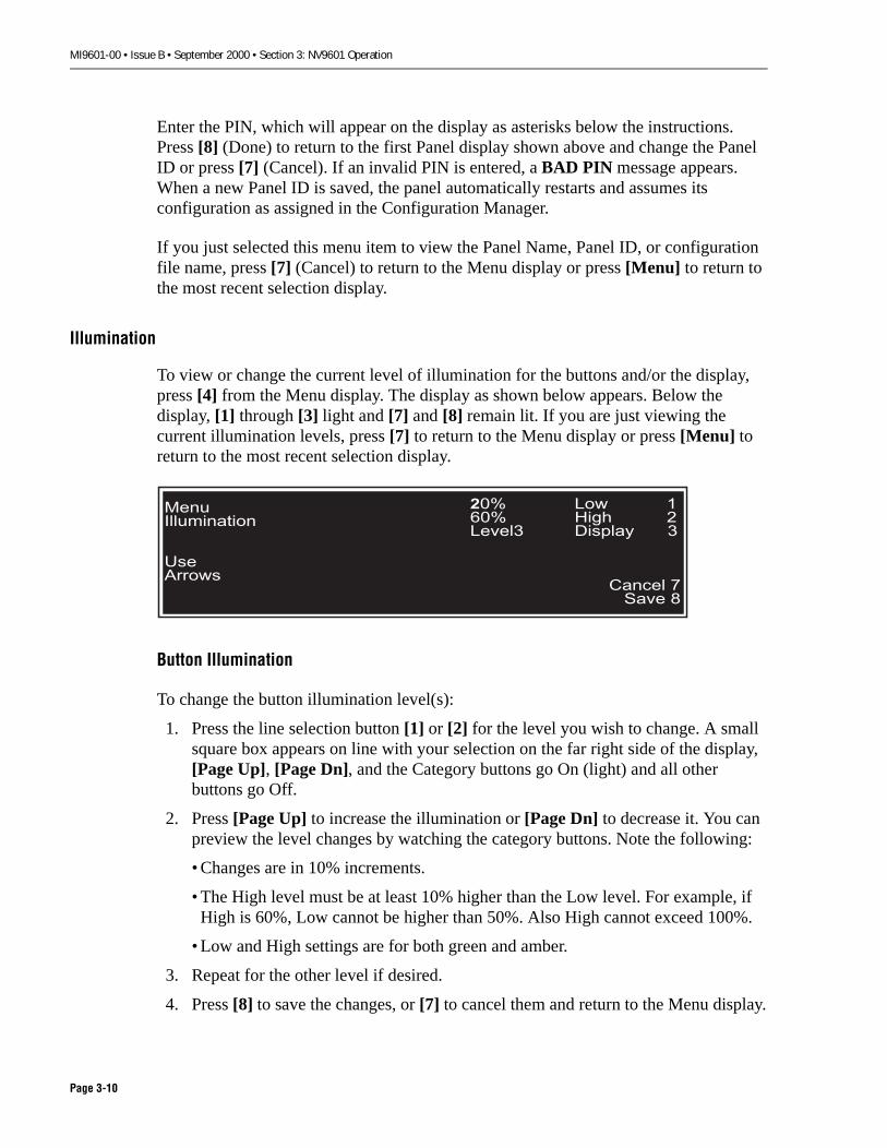
MI9601-00 • Issue B • September 2000 • Section 3: NV9601 Operation
Enter the PIN, which will appear on the display as asterisks below the instructions. Press [8] (Done) to return to the first Panel display shown above and change the Panel ID or press [7] (Cancel). If an invalid PIN is entered, a BAD PIN message appears. When a new Panel ID is saved, the panel automatically restarts and assumes its configuration as assigned in the Configuration Manager.
If you just selected this menu item to view the Panel Name, Panel ID, or configuration file name, press [7] (Cancel) to return to the Menu display or press [Menu] to return to the most recent selection display.
Illumination
To view or change the current level of illumination for the buttons and/or the display, press [4] from the Menu display. The display as shown below appears. Below the display, [1] through [3] light and [7] and [8] remain lit. If you are just viewing the current illumination levels, press [7] to return to the Menu display or press [Menu] to return to the most recent selection display.
Button Illumination
To change the button illumination level(s):
1. Press the line selection button [1] or [2] for the level you wish to change. A small square box appears on line with your selection on the far right side of the display, [Page Up], [Page Dn], and the Category buttons go On (light) and all other buttons go Off.
2. Press [Page Up] to increase the illumination or [Page Dn] to decrease it. You can preview the level changes by watching the category buttons. Note the following:
• Changes are in 10% increments.
• The High level must be at least 10% higher than the Low level. For example, if High is 60%, Low cannot be higher than 50%. Also High cannot exceed 100%.
• Low and High settings are for both green and amber.
3. Repeat for the other level if desired.
4. Press [8] to save the changes, or [7] to cancel them and return to the Menu display.
Menu Illumination
UseArrows
20% Low 160% High 2Level3 Display 3
Cancel 7 Save 8
Page 3-10
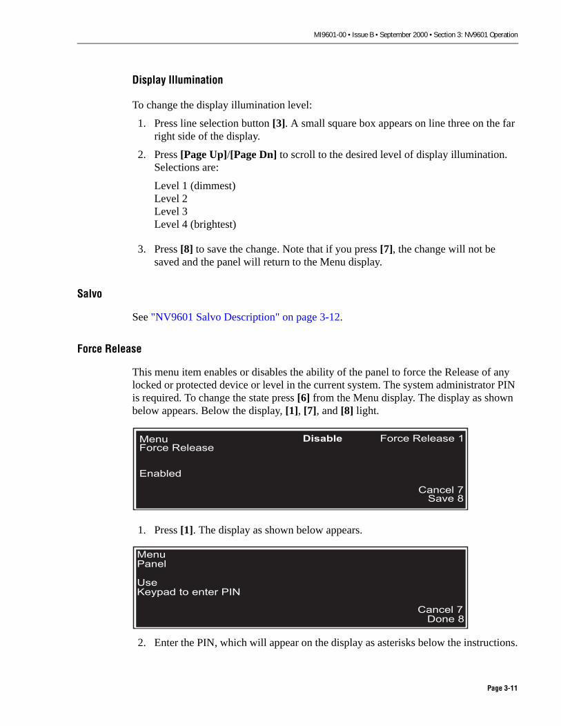
MI9601-00 • Issue B • September 2000 • Section 3: NV9601 Operation
Display Illumination
To change the display illumination level:
1. Press line selection button [3]. A small square box appears on line three on the far right side of the display.
2. Press [Page Up]/[Page Dn] to scroll to the desired level of display illumination. Selections are:
Level 1 (dimmest)Level 2Level 3Level 4 (brightest)
3. Press [8] to save the change. Note that if you press [7], the change will not be saved and the panel will return to the Menu display.
Salvo
See "NV9601 Salvo Description" on page 3-12.
Force Release
This menu item enables or disables the ability of the panel to force the Release of any locked or protected device or level in the current system. The system administrator PIN is required. To change the state press [6] from the Menu display. The display as shown below appears. Below the display, [1], [7], and [8] light.
1. Press [1]. The display as shown below appears.
2. Enter the PIN, which will appear on the display as asterisks below the instructions.
Menu Force Release
Enabled
Disable Force Release 1
Cancel 7 Save 8
MenuPanel
UseKeypad to enter PIN
Cancel 7 Done 8
Page 3-11

MI9601-00 • Issue B • September 2000 • Section 3: NV9601 Operation
3. Press [8] (Done) to return to the first force Release display shown above or press [7] (Cancel). If an invalid PIN is entered, a BAD PIN message appears.
4. Press [7] (Cancel) to return to the Menu display or press [Menu] to return to the most recent selection display.
Exit
Press [8] from the main Menu display to return to the most recent selection display.
NV9601 SALVO DESCRIPTION
The following discusses how to create, save, and clear local salvos and how to execute system and local salvos. Note that execution of a one-time salvo in the Multi-Destination mode is covered in NV9601 Operating Procedures.
Create, Save, and Clear a Local Salvo
To create, save, and clear a local salvo, press [5] (Salvo) from the Menu display. This opens the Salvo menu display similar to the one shown below. Line selection buttons [1], [2], [4], [5] and [8] light. Items in the Salvo menu are described below. See “Executing a Salvo” later in this section for information about executing a saved salvo.
Start Salvo Record - Press [1] to begin recording commands which will be executed when this salvo is selected. When the salvo is executed, all recorded commands will execute. Note that a local salvo must be recorded and saved to be available for selection. Salvos are functional within and across X-Y and Multi-Destination modes. When this item is active, the menu changes to Stop Salvo Record. Commands are
� Note: Salvos created and saved by this function are local salvos. They are executed solelyby this panel and only this panel can delete (clear) them. System salvos are created by theSystem Administrator and cannot be altered at the panel. Local salvos are retained whenthe panel is restarted.
MenuSalvo
Start Salvo Record 1Pause Salvo Record 2Save Salvo 3Cancel Salvo Record 4Erase Local Salvo 5
Exit 8
Page 3-12
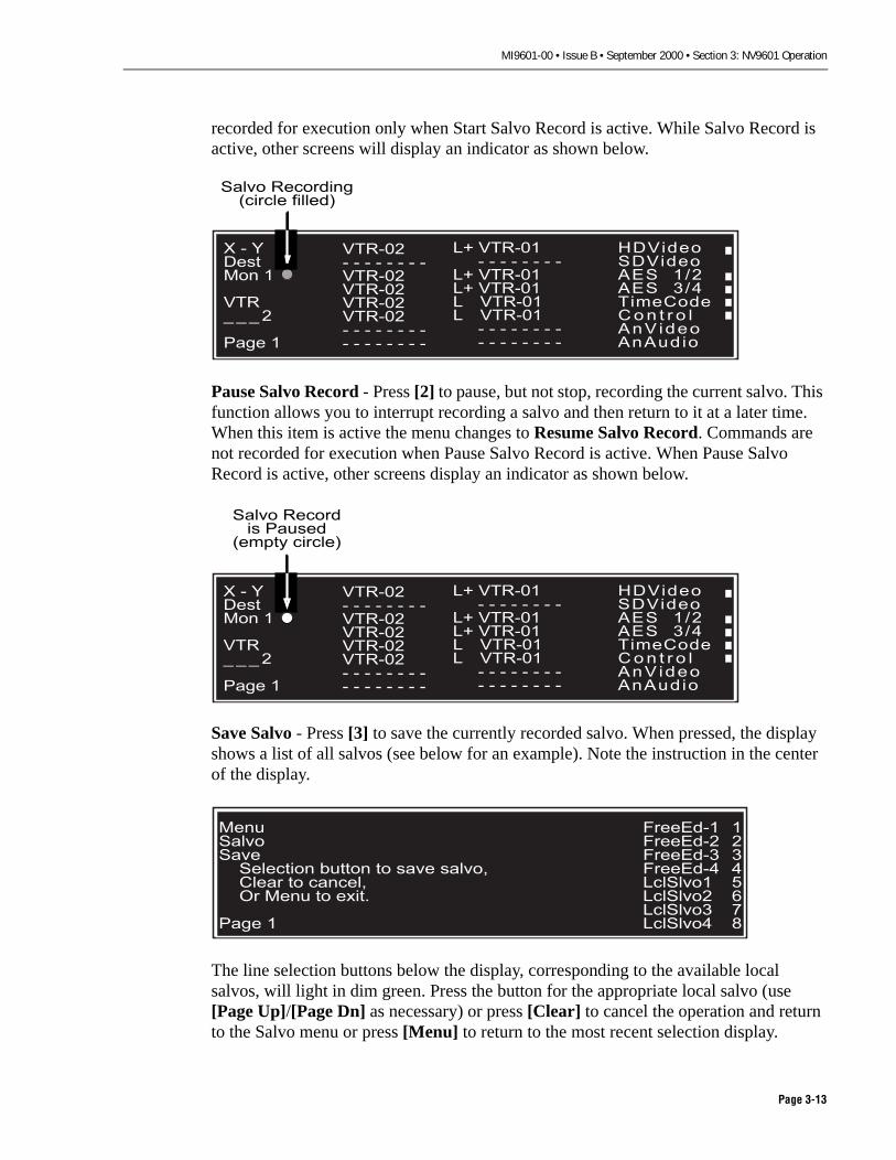
MI9601-00 • Issue B • September 2000 • Section 3: NV9601 Operation
recorded for execution only when Start Salvo Record is active. While Salvo Record is active, other screens will display an indicator as shown below.
Pause Salvo Record - Press [2] to pause, but not stop, recording the current salvo. This function allows you to interrupt recording a salvo and then return to it at a later time. When this item is active the menu changes to Resume Salvo Record. Commands are not recorded for execution when Pause Salvo Record is active. When Pause Salvo Record is active, other screens display an indicator as shown below.
Save Salvo - Press [3] to save the currently recorded salvo. When pressed, the display shows a list of all salvos (see below for an example). Note the instruction in the center of the display.
The line selection buttons below the display, corresponding to the available local salvos, will light in dim green. Press the button for the appropriate local salvo (use [Page Up]/[Page Dn] as necessary) or press [Clear] to cancel the operation and return to the Salvo menu or press [Menu] to return to the most recent selection display.
� � ������ �
������
���� �
������ � � � � � � � ����� ����� ����� ������ � � � � � � �� � � � � � � �
�� ������ � � � � � � �
�� ������� ������� ������� �����
� � � � � � � �� � � � � � � �
�� ����� ������ ������ �!��"�#��#� � $ %�� ������&��
��%' ��($����)(�$(%� *�%%��+
� � ������ �
������
���� �
������ � � � � � � � ����� ����� ����� ������ � � � � � � �� � � � � � � �
�� ������ � � � � � � �
�� ������� ������� ������� �����
� � � � � � � �� � � � � � � �
�� ����� ������ ������ �!��"�#��#� � $ %�� ������&��
��%' ��($��� ��&���
)�"*�+ (�$(%�,
MenuSalvoSave Selection button to save salvo, Clear to cancel, Or Menu to exit.
Page 1
FreeEd-1 1FreeEd-2 2FreeEd-3 3FreeEd-4 4LclSlvo1 5LclSlvo2 6LclSlvo3 7LclSlvo4 8
Page 3-13

MI9601-00 • Issue B • September 2000 • Section 3: NV9601 Operation
Note that if a Salvo has been recorded but not yet saved, other screens will display an indicator as shown below.
Cancel Salvo Record - Press [4] to cancel a salvo that has not yet been saved.
Erase Local Salvo - Press [5] to clear the contents of a selected local salvo. When pressed, the display shows a list of all salvos (see below for an example). Note the instruction in the center of the display.
The line selection buttons below the display, corresponding to the available non-empty local salvos, will light in dim green. Press the button for the appropriate salvo (use [Page Up]/[Page Dn] as necessary) or press [Clear] to cancel the operation and return to the Salvo menu or press [Menu] to return to the most recent selection display.
Exit - Press [8] from the Salvo menu to return to the main Menu or press [Menu] to return to the most recent selection display.
� � ������ �
������
���� �
������ � � � � � � � ����� ����� ����� ������ � � � � � � �� � � � � � � �
�� ������ � � � � � � �
�� ������� ������� ������� �����
� � � � � � � �� � � � � � � �
�� ����� ������ ������ �!��"�#��#� � $ %�� ������&��
��%' ��($���)&� �� ��'��*�"+�, (�$(%�-��. ��/
MenuSalvoErase Selection button to erase salvo, Clear to cancel, Or Menu to exit.
Page 1
FreeEd-1 1FreeEd-2 2FreeEd-3 3FreeEd-4 4LclSlvo1 5LclSlvo2 6LclSlvo3 7LcLSlvo4 8
Page 3-14

MI9601-00 • Issue B • September 2000 • Section 3: NV9601 Operation
Executing a Salvo
Press [Salvo] to view the list of available salvos and to select a salvo for execution. When pressed, the display appears similar to the one below. Note that no salvo is selected if this is the initial time [Salvo] has been pressed and after [Clear Prst] has been pressed. Line selection buttons below the display, equal to the number of salvos, will light, as will [Clear Prst]. If more than eight salvos exist, Page 1 appears in the lower left corner of the display and [Page Up] and [Page Dn] can be used to page through the available salvos, which include both system and local salvos.
Press the [1] - [8] button corresponding to the salvo you wish to execute. Note that salvos are mutually exclusive. The display below is an example of pressing [4] (selecting FreeEd-4). The [Take] button lights.
Press [Take] to execute the selected salvo or press [Clear Prst] to return to the first salvo display above. To select another salvo, press the appropriate button.
Press [Salvo] to return the NV9601 to the most recent selection display, maintaining destination and preset selections.
SalvoExecute
Page 1
FreeEd-1 1FreeEd-2 2FreeEd-3 3FreeEd-4 4LclSlvo1 5LclSlvo2 6LclSlvo3 7LclSlvo4 8
SalvoExecuteFreeEd-4
Press TakeTo Execute
Page 1
FreeEd-1 1FreeEd-2 2FreeEd-3 3FreeEd-4LclSlvo1 5LclSlvo2 6LclSlvo3 7LclSlvo4 8
Page 3-15
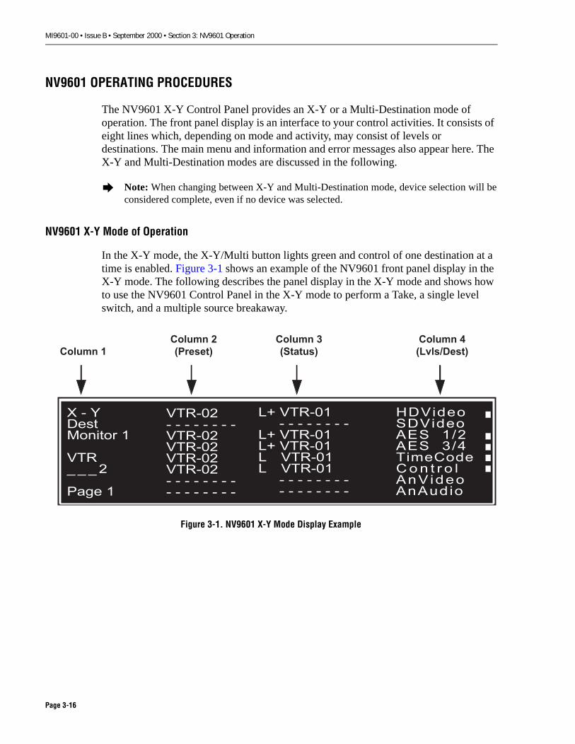
MI9601-00 • Issue B • September 2000 • Section 3: NV9601 Operation
NV9601 OPERATING PROCEDURES
The NV9601 X-Y Control Panel provides an X-Y or a Multi-Destination mode of operation. The front panel display is an interface to your control activities. It consists of eight lines which, depending on mode and activity, may consist of levels or destinations. The main menu and information and error messages also appear here. The X-Y and Multi-Destination modes are discussed in the following.
NV9601 X-Y Mode of Operation
In the X-Y mode, the X-Y/Multi button lights green and control of one destination at a time is enabled. Figure 3-1 shows an example of the NV9601 front panel display in the X-Y mode. The following describes the panel display in the X-Y mode and shows how to use the NV9601 Control Panel in the X-Y mode to perform a Take, a single level switch, and a multiple source breakaway.
Figure 3-1. NV9601 X-Y Mode Display Example
� Note: When changing between X-Y and Multi-Destination mode, device selection will beconsidered complete, even if no device was selected.
� � �������� �
���� � � �
���� �
������� � � � � � � �������������������������� � � � � � � �� � � � � � � �
�� ������� � � � � � � �
�� �������� �������� �������� ������
� � � � � � � �� � � � � � � �
��������������� � ���� ! "��#�$��$ � � %��� ������&��
������ �
������
�� � ��
������ �
�������
������ �
������ ���
Page 3-16

MI9601-00 • Issue B • September 2000 • Section 3: NV9601 Operation
X-Y Mode Display Description
The following description explains the X-Y mode display column by column.
Column 1
Column 1 shows the current mode, the destination device, and the page number. During device selection, this column also shows the device selection sequence. Figure 3-1 shows Column 1 and its contents.
X-Y indicates the current mode is X-Y. In source select mode, all related buttons are low intensity green. (The [Dest] button remains low intensity amber.) ������������������ ��������������������������������������������� ������������������������������ � �����!���������"�#� $%���� ������ ���� �!������������&��� �'
Dest Monitor 1 indicates the currently selected destination is Monitor 1. Note that when entering the X-Y mode from the Multi-Destination mode, the destination shown here will be the most recently selected destination in X-Y Mode.
VTR 2 indicates the source currently being selected for the active levels (i.e., those with a highlighted box at the right of Column 4).
Page 1 indicates this is the first page of multiple pages (i.e., there are additional levels in Column 4 that can be viewed using [Page Dn]). If there is only one page, nothing appears in this location.
X - YDestNO DEST
Select aDeviceTo Begin
- - - - - - - -- - - - - - - -- - - - - - - -- - - - - - - -- - - - - - - -- - - - - - - -- - - - - - - -- - - - - - - -
Page 3-17

MI9601-00 • Issue B • September 2000 • Section 3: NV9601 Operation
Column 2
Column 2 (Figure 3-1) shows the preset sources for the selected levels. A different Preset may be selected for each level. If a Preset is not available or possible, the field contains dashes (- - -).
The levels selected are: HDVideo, AES 1/2, AES 3/4, TimeCode, and Control.
Dashes (- - -) appear on the SDVideo, AnVideo, and AnAudio lines to indicate they are not defined for this destination’s configuration.
VTR-02 is the preset source device for the destination device Monitor 1.
Note the following:
• If a source is locked, an L appears to the left of that source.
• If a source is protected, a P appears for that source.
• If a level on a source is path locked or path protected (for use with NVISION data routers), an I appears in the status column for that level.
Column 3
Column 3 shows the status of the sources in use. The L indicates VTR-01 is locked to Monitor 1. The + (plus sign) indicates additional information is available. Note that if the status is unknown or unavailable, the field contains asterisks (* * *).
Column 4
Column 4 shows the mnemonic for the levels in the level set for the destination device identified in Column 1. Note that a device’s level set is determined through the Configuration Manager.
• If a level on the destination device is protected, a P appears next to that device.
• If a level on the destination device is locked, an L appears next to that device.
• If a level on a destination device is path locked or path protected (for use with NVISION data routers), an I appears to the left of that level.
� Note: Path Lock or path Protect refers to an automatic system Lock or Protect. A pathLock or path Protect is applied to any device connected to a locked or protected port on anNVISION data router.
Page 3-18

MI9601-00 • Issue B • September 2000 • Section 3: NV9601 Operation
Performing a Take (X-Y Mode)
To perform a Take, select a destination, preset a source, and then execute the switch. Note that you may preset a source and select a destination in any order.
1. Ensure the [X-Y/Mult] button is in X-Y mode (green).
2. To select a destination device:
a. Press [Dest]. All buttons appropriate for destination selection light in low intensity amber.
The current destination appears in Column 1, the status of that destination appears in the Status (third) column, and the levels in the destination’s level set appear in the Lev/Dest (fourth) column.
b. Press [(category)] (for example, VTR). VTR appears in the middle of Column 1. Preset and Status columns display dashes. (If [Clear] is pressed now, the display returns to the last selected destination.)
c. Press [(number)] or press [Scroll] and [Page Up] or [Page Dn] to select from the available devices. The selected destination device appears in Column 1. Level selections and presets which apply to the new destination remain and the [Lock], [Prot], [Hold], and [Save Prst] buttons, as applicable to remaining levels and presets are unaffected. The Status column will update accordingly.
3. To preset a source device:
a. Press [Src]. All buttons appropriate for source selection light in low intensity green.
b. Press [(category)] (for example, VTR). VTR appears in the middle of Column 1.
c. Press [(number)] or press [Scroll] and [Page Up] or [Page Dn] to select from the available devices. The selected number for the device appears in Column 1. The presets will appear in Column 2 on the lines with valid levels.
4. Press [Take]. Each preset source switches to the destination shown in Column 1. The Preset and Status columns update.
Page 3-19
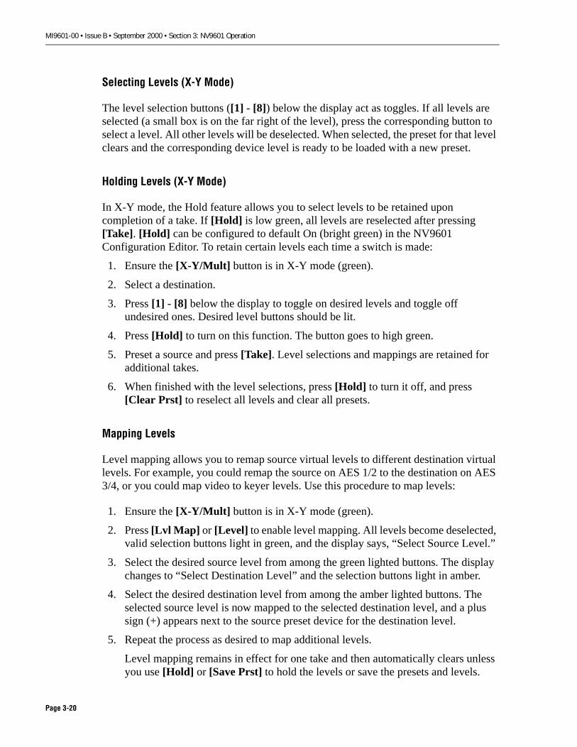
MI9601-00 • Issue B • September 2000 • Section 3: NV9601 Operation
Selecting Levels (X-Y Mode)
The level selection buttons ([1] - [8]) below the display act as toggles. If all levels are selected (a small box is on the far right of the level), press the corresponding button to select a level. All other levels will be deselected. When selected, the preset for that level clears and the corresponding device level is ready to be loaded with a new preset.
Holding Levels (X-Y Mode)
In X-Y mode, the Hold feature allows you to select levels to be retained upon completion of a take. If [Hold] is low green, all levels are reselected after pressing [Take]. [Hold] can be configured to default On (bright green) in the NV9601 Configuration Editor. To retain certain levels each time a switch is made:
1. Ensure the [X-Y/Mult] button is in X-Y mode (green).
2. Select a destination.
3. Press [1] - [8] below the display to toggle on desired levels and toggle off undesired ones. Desired level buttons should be lit.
4. Press [Hold] to turn on this function. The button goes to high green.
5. Preset a source and press [Take]. Level selections and mappings are retained for additional takes.
6. When finished with the level selections, press [Hold] to turn it off, and press [Clear Prst] to reselect all levels and clear all presets.
Mapping Levels
Level mapping allows you to remap source virtual levels to different destination virtual levels. For example, you could remap the source on AES 1/2 to the destination on AES 3/4, or you could map video to keyer levels. Use this procedure to map levels:
1. Ensure the [X-Y/Mult] button is in X-Y mode (green).
2. Press [Lvl Map] or [Level] to enable level mapping. All levels become deselected, valid selection buttons light in green, and the display says, “Select Source Level.”
3. Select the desired source level from among the green lighted buttons. The display changes to “Select Destination Level” and the selection buttons light in amber.
4. Select the desired destination level from among the amber lighted buttons. The selected source level is now mapped to the selected destination level, and a plus sign (+) appears next to the source preset device for the destination level.
5. Repeat the process as desired to map additional levels.
Level mapping remains in effect for one take and then automatically clears unless you use [Hold] or [Save Prst] to hold the levels or save the presets and levels.
Page 3-20

MI9601-00 • Issue B • September 2000 • Section 3: NV9601 Operation
Saving Presets (X-Y Mode)
The Save Presets feature allows you to save preset devices and level mappings for the current destination for switching to other destinations. [Save Prst] can be configured to default On (bright green) in the NV9601 Configuration Editor. To use the feature:
1. Ensure the [X-Y/Mult] button is in X-Y mode (green).
2. Select a destination.
3. Select a source:
a. Press [Src]. All buttons appropriate for source selection go On in low intensity green.
b. Press [(category)] (for example., VTR). VTR appears in the middle of Column 1.
c. Press [(number)]. The selected number for the device appears in Column 1. The presets will appear in Column 2 on the lines of the selected levels.
4. Press [Save Prst].
5. Press [Take] to switch the preset device and level mappings to the destination.
6. Select another destination. The same preset devices and level mappings will apply to that destination if the levels are in the new destination’s level set.
7. Press [Take] to perform the next switch.
8. Repeat destination selections and takes as desired.
9. When you are finished using the saved presets, press [Save Prst] to turn it off, and then press [Clear Prst] to clear all presets.
Page 3-21
MI9601-00 • Issue B • September 2000 • Section 3: NV9601 Operation
Performing a Single Level (Breakaway) Switch (X-Y Mode)
To perform a breakaway switch on only one level of a destination:
1. Ensure the [X-Y/Mult] button is in X-Y mode (green).
2. Select a destination device:
a. Press [Dest]. All buttons associated with destination light in low intensity amber. The current destination appears in the Column 1, the status of that destination appears in the Status (third) column, and the levels in the destination level set appear in the Lev/Dest (fourth) column.
b. Press [(category)] (e.g., VTR). VTR appears in the middle of Column 1. Preset and Status column display dashes. (If [Clear] is pressed now, the display returns to the last selected destination.)
c. Press [(number)]. The selected destination device appears in Column 1. Level selections and presets which apply to the new destination remain and the [Lock], [Prot], [Hold], and [Save Prst] buttons, as applicable to remaining levels and presets are unaffected. The Status column will update accordingly.
3. If all levels had been previously selected, use [1] - [8] below the display to select the desired level. All levels except the currently selected level will be deselected. If all levels had not been previously selected, press [Clear Prst] and then use [1] - [8] below the display to select the desired level.
4. Preset a source device:
a. Press [Src]. All buttons appropriate for source selection go On in low intensity green.
b. Press [(category)] (e.g., VTR). VTR appears in the middle of Column 1 on the display.
c. Press [(number)]. The selected number for the device appears in Column 1. The preset source will be displayed in Column 2 on the line of the selected levels.
5. Press [Take]. The single level switch occurs and the panel returns to the previous display with appropriate Holds, Save Presets, Locks, and Protects intact.
Page 3-22

MI9601-00 • Issue B • September 2000 • Section 3: NV9601 Operation
Performing Multiple Source Breakaways (X-Y Mode)
To perform multiple source breakaways:
1. Ensure the [X-Y/Mult] button is in X-Y Mode (green).
2. Select a destination device:
a. Press [Dest].
b. Press [(category)] (for example, VTR). VTR appears in the middle of Column 1.
c. Press [(number)]. The selected destination device appears in Column 1. Level selections and presets which apply to the new destination remain and the [Lock], [Prot], [Hold], and [Save Prst] buttons, as applicable to remaining levels and presets are unaffected. The Status column will update accordingly.
3. Press [1]-[8] buttons below the display to select the desired level(s) for a source.
4. Select the source:
a. Press [Src]. All source selection buttons light in low intensity green.
b. Press [(category)] (e.g., VTR). VTR appears in the middle of Column 1.
c. Press [(number)]. The selected number for the device appears in Column 1. The presets will appear in Column 2 on the lines of the selected levels.
5. Press the [1] - [8] buttons below the display to toggle (deselect) the current levels off and to select one or more different levels for another source.
6. Repeat the preceding steps for all desired sources.
7. Press [Take] to complete the switch.
Page 3-23
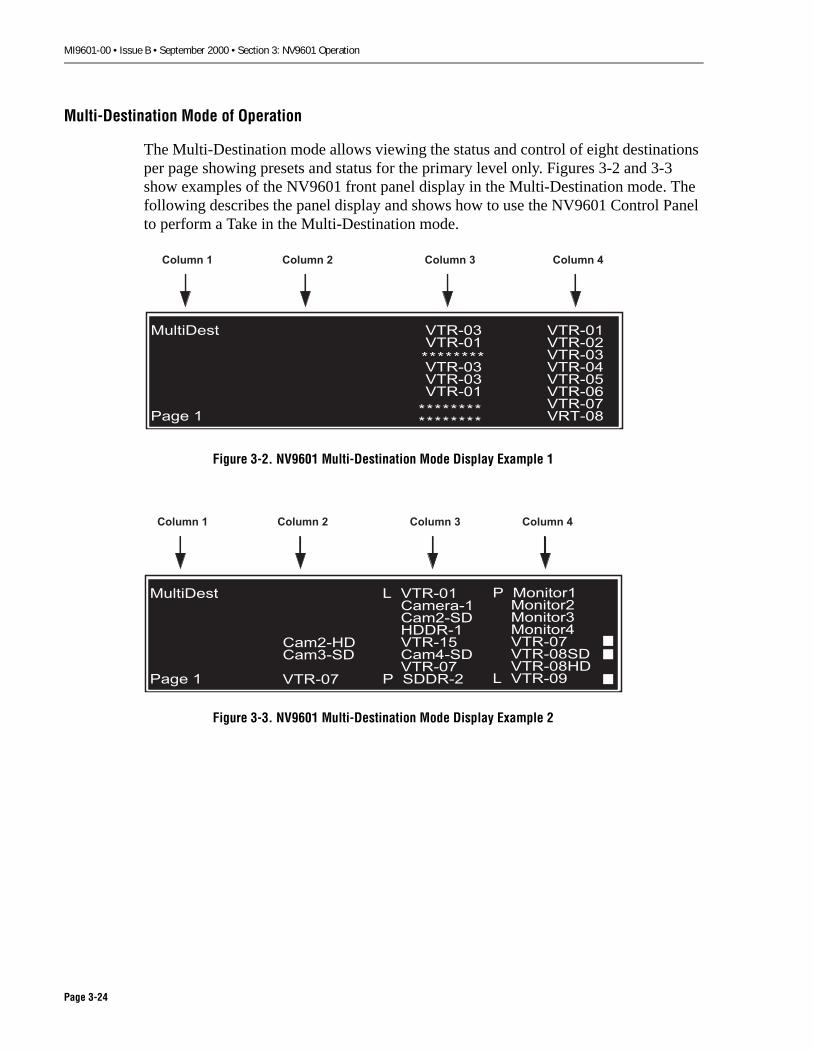
MI9601-00 • Issue B • September 2000 • Section 3: NV9601 Operation
Multi-Destination Mode of Operation
The Multi-Destination mode allows viewing the status and control of eight destinations per page showing presets and status for the primary level only. Figures 3-2 and 3-3 show examples of the NV9601 front panel display in the Multi-Destination mode. The following describes the panel display and shows how to use the NV9601 Control Panel to perform a Take in the Multi-Destination mode.
Figure 3-2. NV9601 Multi-Destination Mode Display Example 1
Figure 3-3. NV9601 Multi-Destination Mode Display Example 2
���������
��
�����������
�����������������
����� ������������������������������������������
��������
����������������
������ � ������ ������ ������ �
���������
��
� ����� ����� ����������� ���� �������������
������
������������
������
������� ����������������������������������� ������� ��
� �����!
������ � ������ ������ ������ �
Page 3-24

MI9601-00 • Issue B • September 2000 • Section 3: NV9601 Operation
Multi-Destination Mode Display Description
Column 1 shows the current mode (Multi-Destination). If there are more than eight devices, Column 1 also shows the page number.
Column 2 shows the preset sources, if any, for the selected destinations (i.e., those destinations with a box next to them in Column 4). In Figure3-2, no destination is selected so Column 2 is blank. In Figure 3-3, destinations VTR-07, VTR-08SD, and VTR-09 have been selected and, therefore, the associated presets appear in Column 2.
Column 3 shows the status of the primary level for each destination in Column 4. Note that if the primary level of the source is locked, an L appears to the left of that source and if protected, a P appears as shown in Figure 3-3. If the primary level of the source is path locked or path protected (for NVISION data routers), an I appears to the left of the destination.
Column 4 shows the destination assigned through the NV9601 Configuration Editor and at the NV9601 Panel. Note that if the primary level of a destination is locked, an L appears to the left of that destination and if protected, a P appears as shown in Figure 3-3. If the primary level of a destination is path locked or path protected (for NVISION data routers), an I appears to the left of the source.
Page 3-25
MI9601-00 • Issue B • September 2000 • Section 3: NV9601 Operation
Performing a Take (Multi-Destination Mode)
Unlike an X-Y Mode take where source and destination selection can be in any order, a Multi-Destination take requires that the destination be selected prior to source selection. To perform a Multi-Destination take:
1. Ensure the [X-Y/Mult] button is in Multi-Destination mode (amber).
2. Select a destination:
a. Press [Page Up]/[Page Dn], if necessary, to display the desired destination.
b. Press [1] - [8] below the display corresponding to the line where the desired destination appears.
3. Select the source:
a. If not already selected, press [Src]. All buttons appropriate for source selection go On (light) in low intensity green.
b. Press [(category)] (e.g., VTR). VTR appears in the middle of Column 1.
c. Press [(number)]. The selected number for the device appears in Column 1. The preset will appear in Column 2 on the line of the selected destination.
4. Select additional destinations and sources as desired. (Note that if you toggle a destination, its preset field is cleared. In Multi-Destination mode, destination selections are mutually exclusive unless [Hold] is on, so you don’t need to toggle off the destination.)
5. Press [Take] to complete the switch.
� Note: In Multi-Destination mode, destination selections are mutually exclusiveunless [Hold] is active (Hi amber).
Page 3-26

MI9601-00 • Issue B • September 2000 • Section 3: NV9601 Operation
Performing a One Time Salvo (Multi-Destination Mode)
To allow multiple sources to be sent to multiple destinations, as in a one time salvo:
1. Ensure the [X-Y/Mult] button is in Multi mode (amber).
2. Select a destination:
a. Press [Page Up]/[Page Dn], if necessary, until the desired destination is on the display.
���������(� ��%������������������������ �������������� !��&� ��#���� ���� �������#��
b. Press [1] - [8] below the display corresponding to the line where the desired destination appears.
3. Select the source:
a. Press [Src]. All buttons appropriate for source selection go On in low intensity green.
b. Press [(category)] (e.g., VTR). VTR appears in the middle of Column 1.
c. Press [(number)]. The selected number for the device appears in Column 1. The preset will appear in Column 2 on the line of the selected destination.
4. Repeat steps 2 and 3 until all desired sources/destinations have been set.
5. Press [Take] to complete the switch.
Page 3-27

MI9601-00 • Issue B • September 2000 • Section 3: NV9601 Operation
Performing a Gang or Dub Switch (Multi-Destination Mode)
For this function, destination selections act as toggles and are cumulative (not mutually exclusive), and destination selections are retained after a take. To allow gang or dub switching (i.e., holding destinations) of multiple destinations at the same time with the same source:
1. Ensure the [X-Y/Mult] button is in Multi-Destination mode (amber).
2. Press [Hold]. The previously selected destination remains selected.
3. Use [1] - [8] to deselect a previously selected unwanted destination and to select new destinations. As a destination is selected (toggled On), its preset field is cleared.
4. Select the source:
a. Press [Src]. All buttons appropriate for source selection go On in low intensity green.
b. Press [(category)] (for example, VTR). VTR appears in the middle of Column 1.
c. Press [(number)]. The selected number for the device appears in Column 1. The preset will appear in Column 2 on the lines of the selected destinations.
5. Press [Take] to complete the switch.
If [Hold] is pressed again (toggled Off), selected destinations are retained only until [Take] is pressed. The panel then returns to switching one destination at a time with no destination selected. After [Hold] is toggled Off, selected destinations are also retained until a destination button is pressed.
Page 3-28

MI9601-00 • Issue B • September 2000 • Section 3: NV9601 Operation
Programming a Destination Position
The positions of destinations on the display can be either fixed or user-programmed. Fixed destination positions are configured in the NV9601 Configuration Editor and cannot be changed at the panel. All user-defined destinations are retained on panel restart and cannot be shared with other control interfaces. To change the user-programmable position of a destination on the NV9601 Control Panel:
1. Ensure the [X-Y/Mult] button is in Multi mode (amber).
2. Press [Dest]. The currently selected destination remains selected, all user-programmable destination buttons below the display light dim amber.
3. Use [Page Up]/[Page Dn], if necessary, to locate the destination position you wish to change.
4. Press the [1] - [8] button for that destination. The category buttons light in dim amber. Note that for fixed position destinations, buttons below the display remain Off and category buttons do not light amber.
5. Press [(category)] (e.g., VTR) for the destination device. VTR appears in the middle of Column 1.
6. Press [(number)] for the destination device. The previously selected destination device at the selected position is replaced by the new destination device. The Status column will update for the new device. The [Lock], [Prot], [Hold], and [Save Prst] buttons, as applicable to remaining destinations and presets, for other than the changed destination, are unaffected.
The same destination can be programmed at multiple positions provided those positions are on separate pages.
� Note: The NV9601 Control Panel display only shows the pages for the number ofdestinations defined in the NV9601 Configuration Editor.
Page 3-29

MI9601-00 • Issue B • September 2000 • Section 3: NV9601 Operation
Clearing a Programmed Destination Position
To clear a destination position which was programmed at the panel:
1. Ensure the [X-Y/Mult] button is in Multi-Destination mode (amber).
2. Use [Page Up]/[Page Dn], if necessary, to locate the destination whose position you wish to clear.
3. Press the [1] - [8] button for that destination.
4. Press [Clear]. The Destination and Status columns at that position go blank. The [Lock], [Prot], [Hold], and [Save Prst] buttons, as applicable to remaining destinations and presets, for other destination positions are unaffected.
Page 3-30

MI9601-00 • Issue B • September 2000 • Section 4: NV9601 Maintenance
Section 4: NV9601 MaintenanceThis section explains maintenance and troubleshooting procedures for the NV9601 X-Y Control Panel. The following topics are covered:
MAINTENANCE . . . . . . . . . . . . . . . . . . . . . . . . . . . . . . . . . . . . . . . . . . . . . . . . . . . . . . . . . . 4-2
TROUBLESHOOTING . . . . . . . . . . . . . . . . . . . . . . . . . . . . . . . . . . . . . . . . . . . . . . . . . . . . . . . 4-2
Initialization Routine . . . . . . . . . . . . . . . . . . . . . . . . . . . . . . . . . . . . . . . . . . . . . . . . . 4-2
Firmware Menu. . . . . . . . . . . . . . . . . . . . . . . . . . . . . . . . . . . . . . . . . . . . . . . . . . . . . 4-3
Loss of Contact With Server . . . . . . . . . . . . . . . . . . . . . . . . . . . . . . . . . . . . . . . . . . . . 4-5
ORDERING REPLACEMENT ASSEMBLIES. . . . . . . . . . . . . . . . . . . . . . . . . . . . . . . . . . . . . . . . . 4-6
Contents Page
Page 4-1

MI9601-00 • Issue B • September 2000 • Section 4: NV9601 Maintenance
MAINTENANCE
There is no periodic maintenance required by the NV9601 X-Y Control Panel, other than periodic dusting or cleaning of the front panel to keep grime and dust from accumulating on or around the buttons.
TROUBLESHOOTING
If the panel does not seem to be working correctly:
1. Disconnect and reconnect power.
2. Disconnect and reconnect the Ethernet cable.
3. Reprogram the panel’s configuration as explained under "Configuring the NV9601 Panel" on page 2-2.
If the panel still does not function correctly:
1. Observe the Initialization Routine described below for clues about the nature of the problem.
2. Check the Firmware Menu to verify whether the hardware and firmware are operating.
3. If the panel still does not function correctly, follow the procedure for "Ordering Replacement Assemblies" on page 4-6.
Initialization Routine
The control panel goes through an initialization routine when it is first powered on. This routine consists of the following series of displays that can help you isolate troubles. The first display, shown below, indicates that the panel is trying to acquire an IP address and shows that the panel recognizes it own ID (<x> in the example below).
��� ��
��
Page 4-2
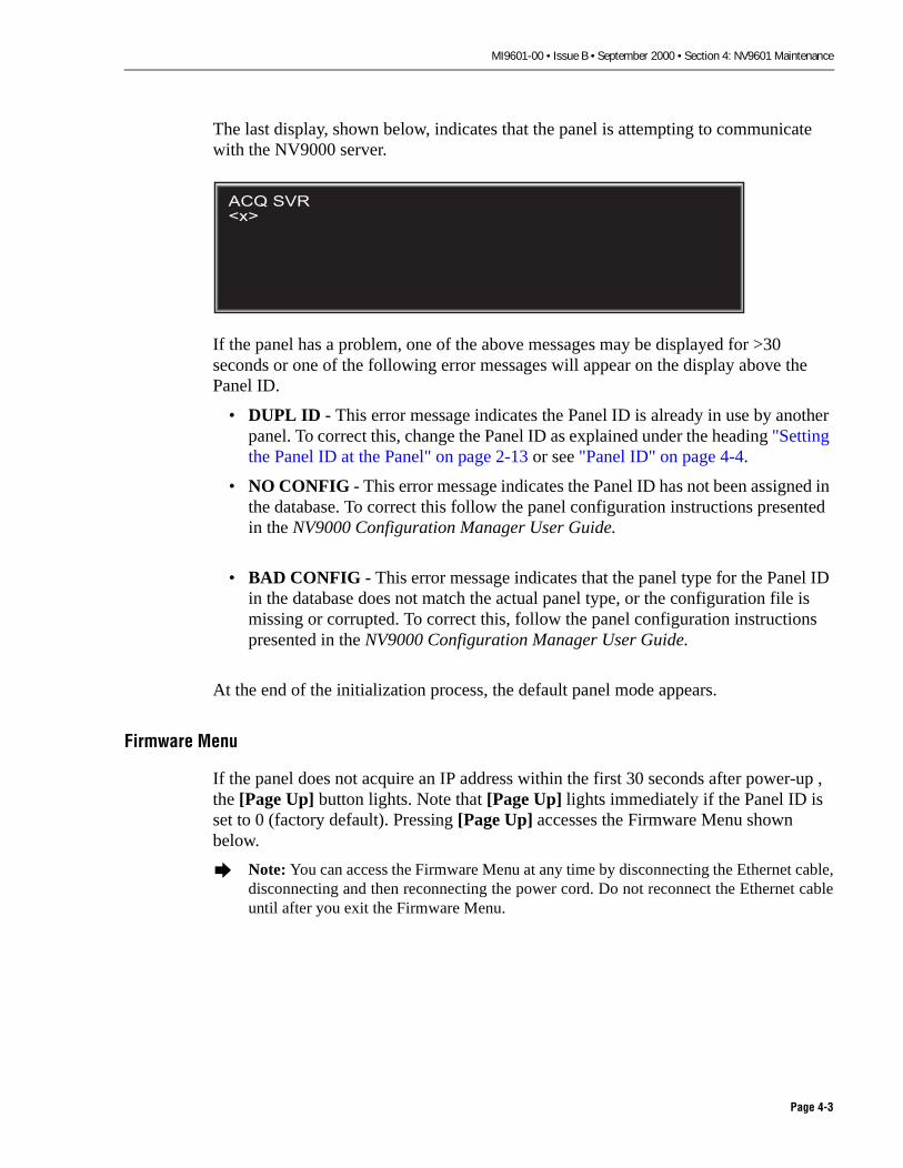
MI9601-00 • Issue B • September 2000 • Section 4: NV9601 Maintenance
The last display, shown below, indicates that the panel is attempting to communicate with the NV9000 server.
If the panel has a problem, one of the above messages may be displayed for >30 seconds or one of the following error messages will appear on the display above the Panel ID.
• DUPL ID - This error message indicates the Panel ID is already in use by another panel. To correct this, change the Panel ID as explained under the heading "Setting the Panel ID at the Panel" on page 2-13 or see "Panel ID" on page 4-4.
• NO CONFIG - This error message indicates the Panel ID has not been assigned in the database. To correct this follow the panel configuration instructions presented in the NV9000 Configuration Manager User Guide.
• BAD CONFIG - This error message indicates that the panel type for the Panel ID in the database does not match the actual panel type, or the configuration file is missing or corrupted. To correct this, follow the panel configuration instructions presented in the NV9000 Configuration Manager User Guide.
At the end of the initialization process, the default panel mode appears.
Firmware Menu
If the panel does not acquire an IP address within the first 30 seconds after power-up , the [Page Up] button lights. Note that [Page Up] lights immediately if the Panel ID is set to 0 (factory default). Pressing [Page Up] accesses the Firmware Menu shown below.
� Note: You can access the Firmware Menu at any time by disconnecting the Ethernet cable,disconnecting and then reconnecting the power cord. Do not reconnect the Ethernet cableuntil after you exit the Firmware Menu.
��� ���
�
Page 4-3

MI9601-00 • Issue B • September 2000 • Section 4: NV9601 Maintenance
Below the display, line selection buttons [1] - [3] and [8] go On (light). Note that you must press [8] (Exit) to exit this menu.
Panel ID
Press line selection button [1] to select Firmware Menu item Panel ID, which allows you to assign a new ID at the panel. The display shown below appears and the keypad buttons and line selection buttons [7] and [8] go On (light). Note that the Panel ID can be changed in this menu even if the Panel ID has been configured as read-only. Use the numeric keypad to enter a new Panel ID. Press [8] to save the new ID or [7] to cancel the operation. Pressing [7] returns you to the Firmware Menu. Pressing [8] causes the panel to immediately assume the configuration it is assigned in the Configuration Manager (assuming the ethernet cable is connected and the NV9000 software is running).
Software Versions
Press line selection button [2] to select Firmware Menu item Software, which allows you to see the version numbers of the currently installed system software. The display shown below appears and line selection button [8] goes On (lights). If you are having problems, write the software numbers down and have them ready when you call NVSION Technical Support. Press [8] (Exit) to return to the Firmware Menu.
�������� �� ��� ��������������
����
�������� ����� ��
��������� �� ����� ��������
��
���� ����
��� ��
�������� ��� ������
���� � ����� ���������
���� �������� �������� ����
�����������������������������������������������������������������
����
Page 4-4
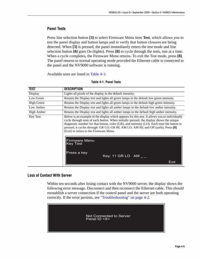
MI9601-00 • Issue B • September 2000 • Section 4: NV9601 Maintenance
Panel Tests
Press line selection button [3] to select Firmware Menu item Test, which allows you to test the panel display and button lamps and to verify that button closures are being detected. When [3] is pressed, the panel immediately enters the test mode and line selection button [8] goes On (lights). Press [8] to cycle through the tests, one at a time. When a cycle completes, the Firmware Menu returns. To exit the Test mode, press [8]. The panel returns to normal operating mode provided the Ethernet cable is connected to the panel and the NV9000 software is running.
Available tests are listed in Table 4-1:
Loss of Contact With Server
Within ten seconds after losing contact with the NV9000 server, the display shows the following error message. Disconnect and then reconnect the Ethernet cable. This should reestablish a server connection if the control panel and the server are both operating correctly. If the error persists, see "Troubleshooting" on page 4-2.
Table 4-1. Panel Tests
TEST DESCRIPTIONDisplay Lights all pixels of the display in the default intensity.
Low Green Retains the Display test and lights all green lamps in the default low green intensity.
High Green Retains the Display test and lights all green lamps in the default high green intensity.
Low Amber Retains the Display test and lights all amber lamps in the default low amber intensity.
High Amber Retains the Display test and lights all amber lamps in the default high amber intensity.
Key Test Below is an example of the display which appears for this test. It allows you to individually cycle through tests of each button. When initially pressed, the display shows the unique diagnostic number for that button, color (GR), and intensity (LO). Each time the button is pressed, it cycles through: GR LO; GR HI; AM LO; AM HI; and Off (unlit). Press [8] (Exit) to return to the Firmware Menu.
�������� ���� ����
����� � �� �� � �� �� �� � � �
����
��� �������� �� ����� ���� �� ���
Page 4-5

MI9601-00 • Issue B • September 2000 • Section 4: NV9601 Maintenance
ORDERING REPLACEMENT ASSEMBLIES
The NV9601 X-Y Control Panel does not contain any user-adjustable or user-serviceable components and is repaired or replaced as a unit. To send the panel back to the factory for repair or replacement, follow the procedure below:
1. Call NVISION Customer Support at the telephone number listed under the heading "TECHNICAL SUPPORT" on page viii.
2. Our support representative will assign you a Return Material Authorization (RMA) number and fax you a Return Authorization Form (Figure 4-1). Do not return equipment without first receiving an RMA#. The form indicates the type of service you are requesting and the urgency of the repair and return shipment.
3. Package the panel in an antistatic bag and place it in a shipping box with plenty of padding material to prevent damage.
4. Address the package using the Shipping Address listed in the front of this manual under the heading "TECHNICAL SUPPORT" on page viii.
5. Send the equipment to NVISION using the shipper and shipping method you prefer. You will pay to ship the equipment to us, and we will pay return freight to you.
6. The factory will use the Return Authorization Form to track receipt of the equipment from you and to note repair or replacement information. If the equipment is out of warranty, we will estimate the cost of repair and call you for authorization.
7. When repair or replacement is complete, we will return ship the equipment to you at our expense if the equipment is in warranty. If the warranty has expired, we will charge you for shipping and handling. The normal shipping method is Second Day unless you specify that you need Next Day or Next Day A.M. shipping due to urgency.
8. NVISION will invoice you the amount quoted if the repair or replacement part is for out of warranty equipment.
Page 4-6

MI9601-00 • Issue B • September 2000 • Section 4: NV9601 Maintenance
Figure 4-1. Typical Return Authorization Form (subject to change)
��������������� ��� ��������������
����� ���������� ��������� ����������
�� ���������� ��� ������������������������������� ���������� ������ ������ � ����������������� ���������� � � ���� ����� � �����������������������������������
������ ����� ����������� � �� �������������! ����������"��� ����������#����� �������������������
$�� �����!� ��� ������������������������������� ����������"� �������� ������ ����������
"%�&'�%�$(��)
� ���� %*����� (��� � (������ ���) ����������
� �����&�� � *���!��+�+ � *���! ,������
����������� ������ ����������
� ���� ����������
����� ����������� ������������ �������!�����������!���"�
�������������������������
�� ��������#��� ���� $���������� ���� ������� ������%� ���������������������
�&���� ���'�&�
��� ���"� ������������ � �������������� ���������������������
���(������������#�� ����������
Page 4-7

MI9601-00 • Issue B • September 2000 • Section 4: NV9601 Maintenance
Page 4-8

MI9601-00 • Issue B • September 2000 • Section 5: Notes
Section 5: NotesThis section includes late-breaking information about the NV9601 X-Y Control Panel. Technical bulletins, application notes, and other current information is included as required. You may also want to use this section to hold your own notes about the control panel and its configuration in your facility.
Page 5-1

MI9601-00 • Issue B • September 2000 • Section 5: Notes
INTRODUCTION
Technical bulletins and other notes will be inserted after this page as required.
Page 5-2

MI9601-00 • Issue C • May 2001 • Index
Index
Numerics
10 Base 2 ���10 Base T ���
A
About This Manual ���AC Power ����Address ����Application Notes ���
B
Boot Up, Panel ����Breakaway Switch ����Breakaway, Multiple Source (X-Y) ����Button Descriptions ���Button Illumination Control ���Button Use ��
C
Cancel Salvo Record ���Category Keys (Key Cap Legends) ��Cautions �Clear (function) ���Clear (Key Cap Legends) ���Clear Preset (function) ���Clear Prst (Key Cap Legends) ���Clearing a Programmed Destination Position
���Configurable Functions, NV9601 ��Configuring the NV9601 ���Connection, Panel NV9000 Server ���Connections
AC Power ����NV9000 Server ���
ConnectorsDiagnostic ���Ethernet ���Power cord ���
Control Panel Specifications ���Conventions Used in This Section ���Copyright and Trademarks ��Current Software Version ��
Customer Support ����
D
Def State (Key Cap Legends) ���Default State (function) ���Destination
Lock ���Destination (function) ���Destination (Key Cap Legend) ���Destination Position, Programming ����Destination selection (display) ���Disclaimer of Liability ��Display Description
Multi Destination Mode ����X-Y Mode ����
Display Illumination Control ����Dub Switch (Multi-Destination Mode) ���
E
Email Address ����NV9000 Server Connection ���Erase Local Salvo ���Ethernet Connection
10 Base 2 ���10Base T ���
European Community (CE) Declaration of Conformance ���
Exit Salvo menu ���Exit, Menu ����
F
FCC (USA) Compliance Statement ���Firmware Menu ��
Panel ID �Panel Tests ��Software Versions �
Force Release ����Free Source (function) ���Free Source (Key Cap Legend) ���Front Matter ��Front Panel Description, NV9601 ���Fuse
AC, Location and Rating ����Fuse holder ���
Index-1

MI9601-00 • Issue C • May 2001 • Index
G
Gang/Dub Switch (Multi-Dest Mode) ��� General Cautions �General Warnings �Getting Started (NV9601) ���
H
Hold (function) ���Hold (Key Cap Legend) ���Hold Levels (X-Y Mode) ���
I
IlluminationControl ���Display ���Push Button ���
Important Safeguards and Notices ��Info (function) ���Info (Key Cap Legend) ���Initialization ����Initialization Routine ��Installation
Applying Power to the Panel ����Configuring the NV9601 Panel ���Connecting Panel to NV9000 Server ���Installing Key Cap Legends ���Installing the NV9601 Panel �� Panel Boot Up ����Physically Installing the Panel �� Setting the Panel ID ����
Installation, Key Cap Legend ���Installation, NV9601 ���Installation, X-Y Control Panel �� Installing Key Cap Legends
Key Cap Legend Meanings ���Legend Installation Procedure ���
Installing the Key Cap Legends ���Installing the NV9601 Panel �� International Power Supply Cords ��
K
Key Cap Legends ���0-9 ���1-8 ���
Index-2
L
Level Mapping ���Level selection (display) ���Line selection (Key Cap Legends) ���Local Salvo
Clear ����Create ����Save ����
LockDestination ���Source ���
Lock (function) ���Lock (Key Cap Legend) ���Loss of Contact With Server ��
M
Mailing Address ����Maintenance ��, ��Mapping Levels ���Menu
Current Software Version �� Exit ����Firmware ��Force Release ����Illumination control ���Panel ID ���Panel Name ���Salvo ����, ����User Name and ID ��
Menu (function) ���Menu (Key Cap Legend) ���Menu Description �� Menu item selection ���Modes of Operation, NV9601 ���
Multi-Destination Mode ���X-Y Mode ���
Multi-Destination Mode ���, ���Clearing a Programmed Destination
Position ���Gang or Dub Switch ��� One Time Salvo ����Programming a Destination Position ����Take ����
Multiple Source Breakaway (X-Y) ����

MI9601-00 • Issue C • May 2001 • Index
N
North American Power Supply Cords ��Notes ���Numeric Entries ��Numeric Keypad (Key Cap Legends) ���NV9601
Boot Up ����Button Use ��Configurable Functions ��Control Panel Specifications ���Front Panel Description ���Installation ���Maintenance ��Modes of Operation ���Multi-Destination Mode ���, ���Operation ���Operational Modes ����Operational Quick Reference ���Rear Panel Description ���X-Y Control Panel Overview ���X-Y Mode ���X-Y Mode of Operation ����
O
Operating Procedures ����Operation ����
Button Descriptions ���General Information ��Menu Description �� Operating Procedures ����
Operational Modes, X-Y Mode ����Operational Quick Reference, NV9601 ���Ordering Replacement Assemblies ��Other Control Panel Features, NV9601 ��Other NV9601 Control Panel Features ��Overview, NV9601 X-Y Control Panel ���
P
Page Down (function) ���Page Down (Key Cap Legend) ���Page Up (function) ���Panel Boot Up ����Panel ID �Panel Name and ID ���Panel Tests ��
Pause Salvo Record ����Phone Numbers ����Power
Connections ����Previous Source (function) ���Programming a Destination Position ����Protect
Source ���Protect (function) ���Push Button Descriptions
Clear ���Clear Prst ���Def State ���Dest ���Free Source ���Hold ���Info ���Lock ���Menu ���Page Down ���Page Up ���Previous Source ���Prot ���Salvo ����Save Presets ���Scrl ���Src ���Take ���XY/Multi ���
Q
Quick Reference, NV9601 ���Quick Start ���
R
Rear Panel Description, NV9601 ���Receiving ���Receiving and Unpacking ���Receiving Inspection ���Related Publications ���Replacement Assemblies, Ordering ��Resume Salvo Record ����Revision History ��
S
Salvo ����
Index-3

MI9601-00 • Issue C • May 2001 • Index
Cancel Salvo Record ���Description ����Erase Local Salvo ���Exit (Menu) ���Local ����Pause Salvo Record ����Resume Salvo Record ����Save Salvo ����Start Salvo Record ����Stop Salvo Record ����System ����
Salvo (function) ����Salvo Description ����Salvo selection (display) ���Salvo, Local
Create, Save, and Clear ����Salvo, One Time (Multi-Dest Mode) ����Save Presets (function) ���Save Salvo ����Saving Presets (X-Y Mode) ����Scrl (function) ���Selecting Levels X-Y Mode ���Setting the Panel ID ����Shipping Address ����Single Level (Breakaway) Switch ����Software Versions �Source (function) ���Source Lock ���Source Protect ���spare fuse holder ���Specifications
Electrical ���Environmental, NV9601 ���Physical ���
Start Salvo Record ����Startup Routine ����Stop Salvo Record ����Support, Customer ����Symbols ��
T
Take ����Take (function) ���Take (Multi-Destination Mode) ����Take (X-Y Mode) ����Take, Single Level ����
Index-4
Technical Bulletins ���Technical Support ����Telephone Numbers ����Troubleshooting ��
Firmware Menu ��Initialization Routine ��Loss of Contact With Server ��
U
Unpacking ���Unpacking Instructions ���User ID �� User Name �� User Name and ID ��
V
Virtual Levels ���
W
Warnings �Web Site ����
X
X-Y Mode ���, ����Display Description ����Hold Levels ���Multiple Source Breakaways ����Saving Presets ����Selecting Levels ���Single Level (Breakaway) ����Take ����
XY/Mult (function) ���
Related Documents