The Iraqi Journal For Mechanical And Material Engineering, Vol.17, No4, Dec 2017 Received: 2016 - 12 -13 Accepted : 2017 - 3 - 15 778 NUMERICAL STUDY ON THE EFFECT OF MERIDIONAL WIDTH VANED DIFFUSER ON THE PERFORMANCE OF A MODIFIED CENTRIFUGAL FLOW COMPRESSOR Layth H. Jawad Department of Mechanical Techniques, Technical Institute of Karbala, Al-Furat Al-Awsat Technical University, IRAQ Email:[email protected] ABSTRACT In This paper, a numerical simulation that was made in the three-dimensional flow, carried out in a modified centrifugal compressor, having vaned diffuser stage, used as an auto- motive turbo charger. In order to study the influence of vaned diffuser meridional outlet section with a different width ratio on the modified centrifugal compressor. Moreover, the performance of the centrifugal compressor was dependent on the proper matching between the compressor impeller along with vaned diffuser. In addition, the curves of polytropic efficiency, total pressure ratio, static pressure and aerodynamic characteristics were compared under different width ratio. In addition, the velocity vectors in diffuser flow passages, the absolute Mach number and the secondary flow in cross-section near the outlet of diffuser were analyzed in detail under width ratio of 0.5, 0.7, 0.8, 1 and 1.2. Another aim of this research was to study and simulate the effect of vaned diffuser on the performance of a centrifugal compressor. The simulation was undertaken by using CFD analysis on aerodynamic flow to predict numerically the performance in terms of pressure ratio, poly tropic efficiency and mass flow rate for the centrifugal compressor stage. The results were generated from CFD (ANSYS CFX) and were analyzed for better understanding of the fluid flow through centrifugal compressor stage and as a result when the width ratio is 0.5, the flow in diffuser passages tends to be uniformity. The backflow and vortex near the pressure surface disappear, and the vortex and detachment near the suction surface decrease. Conclusively, it was observed that the efficiency was increased and both the total pressure ratio and static pressure for 0.5 width ratio are increased . KEYWORDS: Numerical Study; Centrifugal Compressor Performance; Vaned Diffuser; CFD. ريش على لناشر ذير العرض الطولية على تاثيديراسة عد د أداء جريان الطرد المركزيلضاغط ا المطورصة الخكزي المطور الطرد مرور ضاغطذت في طبعاد، نفثي اية لتدفق ثدراسة عدذه البحث تم اجراء د في ه ، مع ناشرراتلسياني لمه كشاحن تربيم استخدا ريش،ت ذيريش بمختلفشر ذي اللناج الطولي لاسة تأثير مقطع الخرو . من أجل درتمد على يع الطرد المركزيء ضاغطن أداى ذلك، فاوة علكزي المطور. ع الطرد المرلضاغطرض على ا نسب العت ال منحنياة بينيت مقارنضافة إلى ذلك، أجرلريش. باشر ذي النا مع الضاغطن ريشة ايح بي التوافق الصح كفاءةيضامختلفة. وامية لنسب العرض اليرودينائص الخصاكي وااتيستي والضغط اكليكية ونسبة الضغط التروب البولو ، تم العرضي قرب مخرج في المقطعلثانويق والتدفق امطلخ ال ما ورقملناشر تدفق امراتت السرعة في ميل متجها تحل لنسب عرضتفصيللناشر بال ا0.5 ، 0.7 ، 0.8 ، 1 و1.2 ومحاكاة تأثيرذا البحث هو لدراسةدف آخر له . وكان ه إف ديل سيخدام تحليلمحاكاة باست. أجريت ا الطرد المركزيلضاغطريش على أداء اشر ذي اللنا ا) س أنسCFX )

Welcome message from author
This document is posted to help you gain knowledge. Please leave a comment to let me know what you think about it! Share it to your friends and learn new things together.
Transcript

The Iraqi Journal For Mechanical And Material Engineering, Vol.17, No4, Dec 2017
Received: 2016 - 12 -13
Accepted : 2017 - 3 - 15 778
NUMERICAL STUDY ON THE EFFECT OF MERIDIONAL
WIDTH VANED DIFFUSER ON THE PERFORMANCE OF A
MODIFIED CENTRIFUGAL FLOW COMPRESSOR Layth H. Jawad
Department of Mechanical Techniques, Technical Institute of Karbala,
Al-Furat Al-Awsat Technical University, IRAQ
Email:[email protected]
ABSTRACT
In This paper, a numerical simulation that was made in the three-dimensional flow, carried
out in a modified centrifugal compressor, having vaned diffuser stage, used as an auto-
motive turbo charger. In order to study the influence of vaned diffuser meridional outlet
section with a different width ratio on the modified centrifugal compressor. Moreover, the
performance of the centrifugal compressor was dependent on the proper matching between
the compressor impeller along with vaned diffuser. In addition, the curves of polytropic
efficiency, total pressure ratio, static pressure and aerodynamic characteristics were
compared under different width ratio. In addition, the velocity vectors in diffuser flow
passages, the absolute Mach number and the secondary flow in cross-section near the outlet
of diffuser were analyzed in detail under width ratio of 0.5, 0.7, 0.8, 1 and 1.2. Another aim
of this research was to study and simulate the effect of vaned diffuser on the performance of
a centrifugal compressor. The simulation was undertaken by using CFD analysis on
aerodynamic flow to predict numerically the performance in terms of pressure ratio, poly
tropic efficiency and mass flow rate for the centrifugal compressor stage. The results were
generated from CFD (ANSYS CFX) and were analyzed for better understanding of the fluid
flow through centrifugal compressor stage and as a result when the width ratio is 0.5, the
flow in diffuser passages tends to be uniformity. The backflow and vortex near the pressure
surface disappear, and the vortex and detachment near the suction surface decrease.
Conclusively, it was observed that the efficiency was increased and both the total pressure
ratio and static pressure for 0.5 width ratio are increased .
KEYWORDS: Numerical Study; Centrifugal Compressor Performance; Vaned
Diffuser; CFD.
دراسة عددية على تاثير العرض الطولي لناشر ذي ريش على
المطورالضاغط الطرد المركزي جريان أداء
الخالصة
، مع ناشر في هذه البحث تم اجراء دراسة عددية لتدفق ثالثي األبعاد، نفذت في طور ضاغط الطرد مركزي المطور
. من أجل دراسة تأثير مقطع الخروج الطولي للناشر ذي الريش بمختلف ذي ريش،تم استخدامه كشاحن تربيني للسيارات
نسب العرض على الضاغط الطرد المركزي المطور. عالوة على ذلك، فان أداء ضاغط الطرد المركزي يعتمد على
كفاءة التوافق الصحيح بين ريشة الضاغط مع الناشر ذي الريش. باإلضافة إلى ذلك، أجريت مقارنة بين منحنيات ال
، تم البولوتروبيكية ونسبة الضغط الكلي والضغط االستاتيكي والخصائص األيرودينامية لنسب العرض المختلفة. وايضا
تحليل متجهات السرعة في ممرات تدفق الناشر ورقم ماخ المطلق والتدفق الثانوي في المقطع العرضي قرب مخرج
. وكان هدف آخر لهذا البحث هو لدراسة ومحاكاة تأثير 1.2 و 1، 0.8، 0.7، 0.5الناشر بالتفصيل لنسب عرض
( CFXأنسس (الناشر ذي الريش على أداء الضاغط الطرد المركزي. أجريت المحاكاة باستخدام تحليل سي إف دي

Layth H. Jawad The Iraqi Journal For Mechanical And Material Engineering, Vol.17, No.4, Dec 2017
779
على التدفق األيروديناميكي للتنبؤ العددي لألداء من حيث نسبة الضغط والكفاءة البولوتروبيكية ومعدل التدفق لطور
الضاغط الطرد المركزي. النتائج التي تم الحصول عليها من سي إف دي حللت لفهم أفضل لتدفق السائل من خالل
، تدفق الجريان في ممرات الناشر يميل 0.5نسبة العرض طور الضاغط الطرد المركزي، ونتيجة لذلك عندما يكون
إلى أن يكون اكثر انتظاما. الجريان العكسي والدوامات قرب سطح الضغط مختفية ، الدوامات وانفصال الجريان قرب
سطح االمتصاص تكون متناقصة. استنتاجيا، لوحظ أن الكفاءة متزايدة ونسبة الضغط الكلي والضغط االستاتيكي
. كانت متزايدة 0.5لنسبة العرض
NOMENCLATURE
CFD Computational Fluid dynamics
CAD Computer Aid Design
IGES Initial Graphics Exchange Specification
TE Trailing Edge
LE Leading Edge
Pt Total Pressure
Ps Static Pressure
Pr Pressure ratio
Tt Total Temperature
Ts Static Temperature
Mabs Absolute Mach Number
Mrel Relative Mach Number
Cm Meridional Velocity
R Blade Radius Location
Z Blade Axial Location
k-ω-SST K-Omega Turbulence Model
k-ɛ k-Epsilon Turbulence Model
3D Three Dimensions
W1 Inlet Width Diffuser
W2 Outlet Width Diffuser
1. INTRODUCTION
In these days, interest has more progressively been devoted to the development of
turbochargers because of their compact size, large capacity, high performance, and ability
to improve volumetric efficiency. Turbochargers are broadly used in many applications,
such as marine, diesel engines, automobile engines, and small gas turbines for aircraft
engines. The improvement of turbocharger compressor performance and the extension of
the stable operating ranges are becoming critical for the viable future of low emission
engines. In centrifugal compressor case, it is known that unsteady behaviour becomes
apparent when the air mass flow through the compressor is lower than the critical level.
This unstable phenomenon is denoted as a surge and corresponds to a backflow of
compressed fluid through the compressor into its inlet. Generally, the performance of a
centrifugal compressor is expressed as a relationship between the mass flow rate and the
pressure ratio on a line with a constant number of revolutions.
Furthermore, the influences of the different diffuser meridian channel width ratios
on the compressor performance under design conditions show a remarkable significance in
terms of improving the efficiency of the whole machine in a micro gas turbine centrifugal
compressor Yang [2011].The effect of pulsating flow inside a centrifugal compressor and
the corresponding pressure pulses on the compressor surge line can be very important
because the pulsating flow is in the range of 40-67 Hz (corresponding to characteristic

NUMERICAL STUDY ON THE EFFECT OF MERIDIONAL Layth H. Jawad
WIDTH VANED DIFFUSER ON THE PERFORMANCE OF
A MODIFIED CENTRIFUGAL FLOW COMPRESSOR
780
pulsation when boosting an internal combustion engine) which increases the surge margin
Galindo [2009].The application of CFD to turbocharger compressor characteristic
predictions over a range of speed, to develop an efficient methodology for analysing the
turbocharger compressor performance, and to compare the computation versus rig
measurements Baris [2011].In addition, the stall flow phenomenon inside a turbocharger
centrifugal compressor with a vaneless diffuser simulated numerical and the amplitude of
the static pressure oscillation at this frequency in the diffuser is increased with the
reduction in compressor mass flow, the results show that there is a distinct stall frequency
at the given compressor speed Guo [2007].The analytical model for the centrifugal
compressor was proposed to predict the compressor performance such as outlet pressure,
efficiency and losses. The model provides a valuable tool for evaluating the system
performance as a function of various operating parameters Jiang [2006]. The compressor
performance map is described experimentally for characterization of the automotive
turbocharger, and a mathematical tool has been developed for marking out surge operation
points from stable compressor points Galindo [2006]. The contribution to the design
methodology and performance assessment of low solidity vaned diffusers to understand the
pressure recovery phenomena in each of the three types of diffusers, and the effect of
design parameters on performance was studied by Engeda [2003]. The effect of impeller
exit width trimming was studied and discussed along with the effect on overall
performance on the basis of experimental data for two impellers. One with a low flow
coefficient and the other with a high flow coefficient, blade loading and impeller diffusion
was examined by Engeda [2007].
The stable working conditions and surge phenomena were simulated and boundary
was used as the Method of Characteristics to determine the flow conditions at compressor
inlet and outlet. To downsize the engine displacement to increase the power output and to
reduce fuel consumption Galindo [2010].The complex shock waves within the diffuser
throat and impeller inlet, respectively, within high-speed compressors. These flow
phenomena does not occur in low speed compressors and are very significant in the design
of these compressors Cukurel [2010] and Higashimori [2004]. Many researchers have
indicated that suitable treatments can extend the stable operating range of a turbocharger
centrifugal compressor, but the performance is still insufficient under the majority of
conditions.
The aerodynamic performance of centrifugal compressors is bound by surge and
chokes on a compressor performance map. Much effort has been spent to define
performance maps Shook [1995] and Layth [2014] to determine the performance of a new
high speed compressor. The barrier imposed by the surge line, which separates the regions
of stable and unstable operation, is of particular interest due to its close proximity to the
maximum efficiency operating point. The initiation of unstable operation has been studied
by many researchers Gravdahl [2004]. When the mass flow through the compressor is
below the surge line, unstable operation occurs in the form of rotating stall or surge.
One of the important aspects of designing efficient compressors is properly
matching the impeller and diffuser. The importance of this topic was presented by Ziegler
[2003] who showed that the presence of diffuser vanes considerably increases the pressure
at the exit of the impeller, proving that there is a coupling between the impeller and
diffuser. The diffuser used in the compressor must be designed for the mass flow rate, flow
velocities, and flow angles at the exit of the impeller. This can be very challenging due to
the highly unsteady nature of compressors and the jet-wake flow at the exit of the impeller.
The performance of the impeller and diffuser is highly coupled, as shown by
Ramakrishnan [2007]. The potential field generated by the diffuser acting on the impeller
exit flow field is not only driven by geometry but is also dependent on the unsteady

Layth H. Jawad The Iraqi Journal For Mechanical And Material Engineering, Vol.17, No.4, Dec 2017
781
diffuser loading. The potential field is the effect the geometry that it has on the pressure in
the airflow. This diffuser loading is in turn a function of the rotating impeller potential
field and the highly three-dimensional velocity field produced by the impeller. The diffuser
potential field acting on the impeller has been studied using CFD by Barry [1991]. Within
the impeller passage, there are high and low momentum regions known as the jet and
wake, which have been studied by Gallier [2007]. These zones not only vary along the
circumference of the impeller, but also along the span, from the hub to the shroud. As flow
emerges from the impeller, the blade forces on the fluid are lost, and the jet and wake
regions undergo rapid mixing within the vaneless space. The design of the vaneless space
has a significant impact on the overall performance of the compressor, including operating
range, stability limits, viscous loss, and diffuser separations. Some of the earlier models
based on low-speed compressors showed complete mixing within the vaneless space.
Investigations on high-speed machines, such as in Ziegler [2007], have shown that the
mixing process is not sufficient to produce a uniform flow field at the leading edge of the
diffuser. The flow at the inlet of the diffuser is made up of shocks, partial separations,
varying momentum and incidence angles. The interaction between the diffuser and
impeller makes it difficult and impossible to predict the behavior of these flow
irregularities and to study one isolated from the other respectively. The degree of these
impeller-diffuser interactions is highly dependent on the radial gap between the impeller
exit and diffuser inlet along with the diffuser vane geometry. Due to this dependence, it is
important for the designer to understand the effects of these geometries in order to properly
match these components. The angle of the diffuser vanes is also an important aspect of the
performance due to the varying incident angles occurring at the diffuser inlet because of
the unsteady flow at the exit of the impeller. There are several studies that have been
conducted on the effects of radial gap and vane angle such as the work of Ibaraki [2007].
In the light of the facts given above, the work reported in this paper deals with numerical
investigations on interaction of vaned diffuser with modified centrifugal compressor
impeller where CFD simulations and flow behavior of each conventional and modified
centrifugal compressor impeller with vaned diffuser configurations were performed. In this
paper, the study is focused on the effect of different diffuser meridional passage width
ratios on the compressor performance to achieve high quality flow and further performance
improvement of the turbocharger compressor.
2. DESIGN & SPECIFICATIONS
The compressor studied was a centrifugal compressor with vaned diffuser stage
model. The inflow and the outflow of the fluid zone were as shown in Figure 1.under the
same geometric conditions except for meridional passage width, keeping the diffuser
meridional passage inlet W1 unchanged, changing the outlet width W2 selecting, a different
width ratio of the diffuser meridional passage W2/W1=0.5, 0.7, 0.8, 1 and 1.2 respectively.
The main geometry features it’s was from a unique geometry model TD04-10T4
turbocharger. The dimensions of the modified compressor vaned diffuser are given in
Table 1.
Figure 2 shows the geometry of the modified compressor wheel vaned diffuser stage
comprising of six main impeller blades, 12 splitter blades and 19 diffuser vanes. The CFD
computations for the modified designs were performed on the geometries. All the surface
geometry, inlet, exit, and periodic boundaries, were defined via computer-aided design
(CAD) as Initial Graphics Exchange Specification (IGES) parts.
NUMERICAL STUDY ON THE EFFECT OF MERIDIONAL Layth H. Jawad
WIDTH VANED DIFFUSER ON THE PERFORMANCE OF
A MODIFIED CENTRIFUGAL FLOW COMPRESSOR
782
3. CFD METHODOLOGY
3.1 Grid Generation
The surface mesh is generated by using a re-triangulation mesh on the impeller and splitter
surfaces. The surface repair tools have sufficient control to allow the analysis by choosing
among the components to include and exclude in the meshing. This is to control the size of
the triangulations in various parts by using surface curvature or by defining local
refinement zones. Once these surface mesh control settings are defined, the tool retains the
association with the imported CAD parts. This makes parametric modelling of the
components very easy. The volume mesh is generated by using a polyhedral, as validated
for flow and thermal solutions Peric [2004] and Mendonca [2008]. The polyhedral cell
mesh consists of 12-16 faces, agglomerated from the underlying automatically generated
tetrahedral mesh. Polyhedral meshes offer significant advantages over traditional mesh
types. Like tetrahedral and unlike hexahedral meshes, they can be automatically generated.
Polyhedral meshes exhibit far less numerical diffusion compared to tetrahedral meshes
because of the greater likelihood of face alignment to the flow. Gradient calculations are
more accurate due to the greater number of face neighbours. Cell counts are typically a
third of the equivalent tetrahedral meshes for similar fineness of resolution. It all means
that polyhedral meshes run faster, are more accurate and converge more robustly than
tetrahedral meshes Peric [2004]. The computational grid, for the modified impeller blade
passage with two splitters comprising exactly 442035 structured hexahedral elements in
multi-block environment, for the vaned diffuser passage comprising 363300 hexahedral
elements were generated using TurboGrid. Sufficiently fine grid elements were created in
the impeller tip clearance region, around the impeller, and at the hub and shroud walls, as
shown in Figure 3. Sufficient mesh quality checks were performed by keeping the
parameters like mesh angle and determinants within acceptable limits.
3.2 Fluid Flow Modelling
The fluid zone comprises of one area enveloping all the rotating parts (blades and
hub) and the other area of the stationary parts (shroud, inlet, outlet and vaned diffuser). The
left and right boundaries are defined as periodic. Turbulence is modelled using the k-ω-
SST model. This model is a zonal combination of k-ω near the wall, nominally in the
boundary layer, and k-ɛ away from the walls. When the near-wall mesh is compatible with
the wall-function approach, this model behaves predominantly as a high-Reynolds number
k-ɛ formulation. All surfaces are treated as adiabatic. Total pressure and total temperature
are applied to the inflow inlet boundary. The outflow outlet condition is set to static
pressure. The exit static pressure is modified in stages, and a new analysis is run to
determine the mass flow rates. The exit pressure is adjusted from the surge to the choke
limit to give constant speed compressor performance curves.
3.3 Boundary Conditions Used in Simulation
Boundary conditions specification is an essential part in using CFD. They vary from
symmetric to periodic, from wall to another, and from inlet to outlet. As was mentioned
earlier specifying the boundary conditions is a pre-processing process. The boundary
conditions used in this work are as shown in Figure 4 and listed in table 2:
4. RESULTS
The numerical method used by the solver part of the software requires an iterative
process in order to obtain a solution. In general, the residual magnitude should decrease as

Layth H. Jawad The Iraqi Journal For Mechanical And Material Engineering, Vol.17, No.4, Dec 2017
783
the solution converges. When the magnitude of the residuals for all the quantities falls
below the convergence level, the solver will stop iterating, and the results will be exported
for post-processing. Figure 5 shows the total-total Polytropic efficiency and total-total
pressure ratio with respect to width ratio curves, considering the best performance was at
0.5 width ratio, and the worst one was at 1.2 width ratio. Moreover, it is clearly seen that
the width ratio does have an important impact on the efficiency and pressure ratio. The
reason might be due to its own characteristics of this type of centrifugal compressor.
The results are compared with experimental work data which was presented for validation
Jawad [2014]. Figure 6 shows the predicted compressor characteristic at the four speeds
investigated versus the rig measurements. The calculations at low pressure ratio points for
all speeds correspond very closely in predicting mass-flow to the measurements. At the
high speed line, the 60,000 and 80,000 RPM predictions are in good agreement with the
experiments, whereas at the highest speed, 100,000 RPM deviation from the measurements
of 3-5% is observed. At the higher pressure ratios, and especially near the surge line, the
deviation is up to 4.5% over-prediction at any given speed.It is found that the behaviour of
low pressure ratio point for a corresponding specific speed very closely to the experimental
work data as shown in figure 6 .
Figure 7 shows the meridional velocity difference across the trailing edge (TE) Spanwise
of the centrifugal compressor impeller configurations for a different width ratio it is clearly
seen that meridional velocity is increasing at mid Spanwise between hub and shroud, and
then it is decreasing at a shroud, the reason due to tip clearance between shroud and
impeller tip.
Figure 8 shows the meridional velocity difference across the trailing edge (TE) Spanwise
of the vaned diffuser configurations for a different width ratio it is clearly seen that
meridional velocity is increasing at 0.2 spanwise between hub and shroud, and then it is
decreasing at a shroud, the reason due to narrow passage between shroud and vaned tip.
Obviously, the meridional velocity at 0.5 width ratio is the higher than the others’ types,
the reason behind that due to an outlet narrow passage between shroud and vaned tip.
Figure 9 shows the relative Mach number difference across the trailing edge (TE)
Spanwise of the centrifugal compressor impeller; it is clearly seen that relative Mach
number is decreasing for the 0.5 width ratio than others’ width ratios.
Figure 10 shows absolute Mach number difference across the Spanwise location at trailing
edge of the vaned diffuser; it is visibly seen that Mach number is higher at 0.5 width ratio
than others’ types of width ratios.
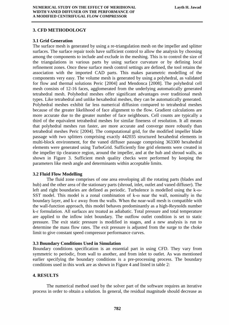
Figure 1 1 shows absolute Mach number difference across the streamwise location, from
inlet impeller to outlet vaned diffuser; it is visibly seen that Mach number is higher at
space between impeller exit and vaned inlet; therefore, it is very important to take into
account the impact of a space ratio in design.
Figure 1 2 shows the static pressure difference across the streamwise location of the
modified vaned diffuser centrifugal compressor for a different width ratio; it is clearly seen
that the static pressure is decreasing at space between exit impeller and inlet vaned
diffuser; moreover, it is obviously seen that static pressure is increasing through vaned
diffuser due to the kinetic energy which is converted into static pressure. Conclusively, the
static pressure for 0.5 width ratio is the higher than others’ types of width ratios.
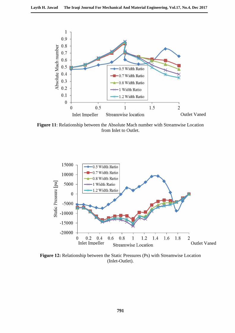
Figure 1 3 shows the velocity vectors magnitude at mid spanwise location for impeller
vaned diffuser configurations in clockwise rotation from the impeller inlet and vaned exit.
It can be seen that the flow conditions in diffuser near the outlet vary obviously under
different width ratio, when the width ratio is 1.2, as a result of meridional passage, a
backflow vortex exists near the pressure surface next to the diffuser outlet. It greatly
increased the flowing loss; therefore, the efficiency and pressure ratio is low; when the

NUMERICAL STUDY ON THE EFFECT OF MERIDIONAL Layth H. Jawad
WIDTH VANED DIFFUSER ON THE PERFORMANCE OF
A MODIFIED CENTRIFUGAL FLOW COMPRESSOR
784
width ratio is 0.8, the backflow vortex and its influence region decrease a lot, when the
width ratio is 0.5, the flow field becomes uniform. Therefore, the flow losses decrease
while the efficiency and pressure ratio becomes higher.
Figure 1 4 shows the contour of relative Mach number at mid spanwise location for
impeller vaned diffuser configurations from the impeller inlet and vaned exit, as an
example of CFD computations. It can be seen no choke of flow at the inlet of the modified
type because of the uniform distribution of the throat area between blade to blade passages.
If we extend the leading edge of the splitters to the leading edge of the full blade, it will
minimize the throat area and cause choking. It can be seen the flow in the space area
between the trailing edge of the impeller, and the leading edge of the vanes' diffuser which
is close to Mach one meaning the space area ratio which is a very important factor to
modify in order to remove any choking of the flow for all configurations of width ratios. It
is clearly seen that the effect of flow vaned angle to increase and decrease the backflow
vortex.
Figure 1 5 shows the contour of static pressure difference on the meridional surface of the
impeller vaned diffuser from the inlet to outlet location for different configurations of
width ratios; it is obviously seen that the effect of outlet vaned width of the distribution of
static pressure, it can be seen evidently the effect of vaned diffuser to increase the static
pressure, the reason behind that due to the kinetic energy which is converted into static
pressure.
Figure 1 6 shows the relative Mach number on a meridional surface of the impeller vaned
diffuser from the inlet to outlet location for different configurations of width ratios. It is
clearly seen that the relative Mach number of 0.5 width ratio type is lower than relative
Mach number of other's types at outlet flow and at the space between impeller exit and
vaned outlet. It is necessary to convert the high kinetic energy to a static pressure through a
diffuser provided downstream of the impeller.
Figure 1 7 shows the contour of meridional velocity from Leading Edge (LE) of impeller to
Trailing Edge (TE) of vaned diffuser for different configurations of a width ratio. It is
clearly seen that the effect of outlet 0.5 width ratio to decrease the meridional velocity
along a meridional length of vaned diffuser. Moreover, the diffuser is used to reduce this
velocity while at the same time it increases the static pressure. It can be seen that the high
velocity is located at space between impeller exit and vane's inlet. As earlier mentioned
that the space area ratio which is a very important factor to modify. The numerical analysis
was carried out including the impeller vaned diffuser flow passage only. The results show
the effect of the outlet width ratio vaned diffuser on the performance of centrifugal
compressor. The modification of a previous design of centrifugal compressor impellers
gives a better performance or a wide operating range. CFD models give a much deeper
understanding of the flow inside a vaned diffuser centrifugal compressor, enabling us to
solve many problems easily and rapidly.
5. CONCLUSIONS
Steady state flow simulations have been conducted in order to analysis, the effects of
the different meridional passage width ratio of vaned diffuser on the centrifugal
compressor performance are systemically simulated and analysed. The Parametric
computations were performed on a 3D-Turbulent CFD to obtain the performance of
backswept impeller configurations at a certain speed; it was 50k RPM. The analysis of the
flow characteristics was also performed to obtain a better understanding of the blade to
blade vaned diffuser compressor behaviours. The results show the range of the best width
ratio is determined. The following conclusions are obtained; firstly, reducing the width

Layth H. Jawad The Iraqi Journal For Mechanical And Material Engineering, Vol.17, No.4, Dec 2017
785
ratio can enhance the performance of centrifugal compressor. When the width ratio is 0.5,
the Polytropic efficiency of the impeller coupled with the vaned diffuser reaches the
highest value 73.52%, and the total pressure ratio gets to the highest value 1.35.secondly,
as the width ratio decrease, the flow in radial direction of the diffuser meridional passage is
squeezed. The backflow and vortex near the pressure surface gradually disappear. The flow
tends to be uniform; hence the efficiency and total pressure ratio are both improved. An
effort was made to model the flow from the inlet to the exit of a centrifugal compressor
stage consisting of all the components in place using CFD tools. The vector plots, contour
plots and Stream line plots are generated for better understanding of fluid flow through
centrifugal compressor stage. Conclusively, the aerodynamic results show that the best
width ratio range of diffuser meridional passage is 0.5 and 0.7. Obviously, the performance
was significantly affected by outlet meridional width passage vaned diffuser.
Table 1: Geometric Features of the Vaned Diffuser Centrifugal Compressor.
(ANSYS BLADE DESIGN)
Centrifugal Compressor Modified
(Double Splitter)
Axial Width of Impeller in Meridional View 30 mm
Inner Radius at Compressor Inlet 8 mm
Outer Radius at Compressor Inlet 35 mm
Impeller Outer Radius 49 mm
Impeller Width at Trailing Edge 6 mm
Number of Blades 18
Number of Splitters 12
Tip Clearance at Shroud 95% Span
Splitter1 angular offset (pitch fraction or location ) 67%
Splitter2 angular offset (pitch fraction or location ) 33%
Number of Diffuser Vanes 19
Vane Inner Radius 61 mm
Vane Outer Radius 82 mm
Vane Inner Axial Width 6 mm
Vane Outer Axial Width 4 mm
Vane Outer Flow angle 30o
Inlet Width Diffuser (W1) 6mm
Table 2: Boundary Conditions Used in CFD Calculations.
Flow angle at domain inlet (degree) (0) Radial Direction
Total temperature at domain inlet (Kelvin) 303
Total pressure at domain inlet (bar) 1.03
Rotational speed (rpm) 50000
Physical Timescale 0.00002
Number of Iteration 100 Stator’s Outlet-Rotor’s Inlet General Connection (Stage) Flow Direction Cylindrical (1,0,0)

NUMERICAL STUDY ON THE EFFECT OF MERIDIONAL Layth H. Jawad
WIDTH VANED DIFFUSER ON THE PERFORMANCE OF
A MODIFIED CENTRIFUGAL FLOW COMPRESSOR
786
Figure 1: Meridional View of the Impeller, Vaned Diffuser, Hub and Shroud.
Figure 2: Isometric 3D View of Modified Vaned diffuser Centrifugal Compressor stage.
Blade Axial location (Z)
Inlet
Outlet
Hub
Shroud
Bla
de
Rad
ius
loca
tion (
R)
Vaned
Diffuser
Mixing
Plane
Impeller
W1
W2
Splitter2
Splitter1
Vaned
Diffuser
Compressor
Impeller

Layth H. Jawad The Iraqi Journal For Mechanical And Material Engineering, Vol.17, No.4, Dec 2017
787
Figure 3: Blade to Blade That is Used in the Simulation
Inlet: the pressure and temperature are
given
Outlet: static pressure is given
Wall (stationery), which is none moving
boundary , this is called shroud
Wall (moving), which is the hub and blade
boundary condition
Figure 4: Boundary conditions specification

NUMERICAL STUDY ON THE EFFECT OF MERIDIONAL Layth H. Jawad
WIDTH VANED DIFFUSER ON THE PERFORMANCE OF
A MODIFIED CENTRIFUGAL FLOW COMPRESSOR
788
Figure 5: Relationship between the Total-Total Polytropic Efficiency and Total-Total
Pressure with Width Ratio at 50% span.
Figure 6: Comparison of Experimental With Numerical Work for Conventional Type

Layth H. Jawad The Iraqi Journal For Mechanical And Material Engineering, Vol.17, No.4, Dec 2017
789
Figure 7: Relationship between the Meridional Velocity (Cm) and Span Normalized at
Trailing edge (TE) of Impeller for Different Width Ratio.
Figure 8: Relationship between the Meridional Velocity (Cm) and Span Normalized at
Trailing edge (TE) of Vaned Diffuser for Different Width Ratio.
Hub Shroud

NUMERICAL STUDY ON THE EFFECT OF MERIDIONAL Layth H. Jawad
WIDTH VANED DIFFUSER ON THE PERFORMANCE OF
A MODIFIED CENTRIFUGAL FLOW COMPRESSOR
790
Figure 9: Relationship between the Relative Mach Number (M rel) and Span Normalized
at Trailing edge (TE) of Impeller for Different Width Ratio.
Figure 10: Relationship between the Absolute Mach number with Spanwise Location at
Trailing Edge (TE) of Vaned Diffuser.
Hub Shroud
Layth H. Jawad The Iraqi Journal For Mechanical And Material Engineering, Vol.17, No.4, Dec 2017
791
Figure 11: Relationship between the Absolute Mach number with Streamwise Location
from Inlet to Outlet.
Figure 12: Relationship between the Static Pressures (Ps) with Streamwise Location
(Inlet-Outlet).
Inlet Impeller
Outlet Vaned
Diffuser
Outlet Vaned
Diffuser
Inlet Impeller
NUMERICAL STUDY ON THE EFFECT OF MERIDIONAL Layth H. Jawad
WIDTH VANED DIFFUSER ON THE PERFORMANCE OF
A MODIFIED CENTRIFUGAL FLOW COMPRESSOR
792
0.5 Width ratio
0.7 Width ratio
0.8 Width ratio
1 Width ratio
1.2 Width ratio
Figure 13: Velocity Vectors at 50% Span Position for Different Width ratio of Vaned
Diffuser

Layth H. Jawad The Iraqi Journal For Mechanical And Material Engineering, Vol.17, No.4, Dec 2017
793
0.5 Width ratio
0.7 Width ratio
0.8 Width ratio
1 Width ratio
1.2 Width ratio
Figure 14: Contour of Relative Mach number at 50% Span Position for Different Width
ratio of Vaned Diffuser.

NUMERICAL STUDY ON THE EFFECT OF MERIDIONAL Layth H. Jawad
WIDTH VANED DIFFUSER ON THE PERFORMANCE OF
A MODIFIED CENTRIFUGAL FLOW COMPRESSOR
794
0.5 Width ratio 0.7 Width ratio 0.8 Width ratio
1 Width ratio 1.2 Width ratio
Figure 15: Contour of Static Pressure on Meridional Surface for Different Width ratio of
Vaned Diffuser

Layth H. Jawad The Iraqi Journal For Mechanical And Material Engineering, Vol.17, No.4, Dec 2017
795
0.5 Width ratio 0.7 Width ratio 0.8 Width ratio
1 Width ratio 1.2 Width ratio
Figure 16: Contour of Relative Mach number on Meridional Surface for Different Width
ratio of Vaned Diffuser.

NUMERICAL STUDY ON THE EFFECT OF MERIDIONAL Layth H. Jawad
WIDTH VANED DIFFUSER ON THE PERFORMANCE OF
A MODIFIED CENTRIFUGAL FLOW COMPRESSOR
796
0.5 Width ratio 0.7 Width ratio 0.8 Width ratio
1 Width ratio 1.2 Width ratio
Figure 17: Contour of Meridional Velocity on Meridional Surface for Different Width
ratio of Vaned Diffuser.
REFERENCES
A. Engeda (2003). Experimental and numerical investigation of the performance of a 240
kW centrifugal compressor with different diffusers. Experimental Thermal and Fluid
Science, 28:55-72.
A. Engeda (2007). Effect of Impeller Exit Width Trimming on Compressor Performance.
Proceedings of the 8th International Symposium on Experimental and Computational
Aerothermodynamics of Internal Flows.ISAIF8- 00135.
B. Cukurel, P.B. Lawless, and S. Fleeter, 2010. Particle Image Velocity Investigation of a
High Speed Centrifugal Compressor Diffuser, Spanwise and Loading Variations.
Journal of Turbomachinery, vol. 132, pp. 1-9.
H. Higashimori, K. Hasagawa, K. Sumida, and T. Suita, 2004. Detailed Flow Study of
Mach number 1.6 High Transonic Flow with a Shock Wave in a Pressure Ratio 11
Centrifugal Compressor Impeller. Journal of Turbomachinery, vol. 126, pp. 473-481.

Layth H. Jawad The Iraqi Journal For Mechanical And Material Engineering, Vol.17, No.4, Dec 2017
797
J.T. Gravdahl and F. Willems, 2004. "Modeling of Surge in Free-Spool Centrifugal
Compressors: Experimental Validation," Journal of Propulsion and Power, vol.20,
pp. 849-857.
J. Galindo,H. Climent, C. Guardiol, A. Tiseira (2009). On the effect of pulsating flow on
surge margin of small centrifugal compressors for automotive engines. Experimental
Thermal and Fluid Science, 33:1163–1171.
J. Galindo,J.R. Serrano , C. Guardiola, and C. Cervello (2006). Surge limit definition in a
specific test bench for the characterization of automotive turbochargers.
Experimental Thermal and Fluid Science 30 (2006) 449–462.
J. Galindo, F.J. Arnau, A. Tiseira and P. Piqueras (2010).Solution of the turbocompressor
boundary condition for one-dimensional gas-dynamic codes. Mathematical and
Computer Modelling 52 (2010) 1288_1297.
K.U. Ziegler, H.E. Gallus, and R. Niehuis, "A Study on Impeller-Diffuser Interaction-Part
I: Influence on the Performance," Journal of Turbomachinery, vol. 125, 2003, pp.
173-182.170.
K. Ramakrishnan, P.B. Lawless, and S. Fleeter, "High Speed Centrifugal Compressor
Aeromechanics - Impeller Unsteady Aerodynamics," AIAA 2007-5020, Cincinnati,
OH: AIAA, 2007, pp. 1-18.
K. Gallier, P.B. Lawless, and S. Fleeter, "PIV Characterization of High Speed Centrifugal
Compressor Impeller-Diffuser Interaction," AIAA 2007-5019, Cincinnati, OH:
AIAA, 2007, pp. 1-8.
K.U. Ziegler, H.E. Gallus, and R. Niehuis, "A Study on Impeller-Diffuser Interaction-Part
II: Detailed Flow Analysis," Journal of Turbomachinery, vol.125, 2003, pp. 183-192.
Layth H. Jawad, S. Abdullah, R. Zulkifli1and W.M.F.W. Mahmood, (2014).Numerical
Study on the Effect of Interaction Vaned Diffuser with Impeller on the Performance
of a Modified Centrifugal Compressor. Journal of Mechanics Vol. 30, April 113-121.
M. Peric, (2004).Flow simulation using control volumes of arbitrary polyhedral shape.
ERCOFTAC Bulletin 62.
Mendonça F, Clement J, Palfreyman D and Peck A,(2008).Validation of Unstructured
CFD Modelling Applied to the Conjugate Heat Transfer in Turbine Blade Cooling.
ETC-8-198, European Turbomachinery Conference, Graz.
O. Baris (2011). Automotive turbocharger compressor CFD and extension towards
incorporating installation effects. Proceedings of ASME Turbo Expo 2011: Power for
Land, Sea and Air GT2011.
Q Guo,H Chen, X-C Zhu, Z-H Du, and Y Zhao (2007). Numerical simulations of stall
inside a centrifugal compressor. Power and Energy IMechE Vol. 221 Part A: J.
R. M. P.J. Shook, W. Oakes, 1994. "The Aerodynamic Performance of a High Speed
Research Centrifugal Compressor Facility," AIAA Paper 1994-2798, pp. 1-9.
S. Ibaraki, T. Matsuo, and T. Yokoyama, "Investigation of Unsteady Flow Field in a
Vaned Diffuser of a Transonic Centrifugal Compressor," Journal of Turbomachinery,
vol. 129, 2007, p. 686.
W. Jiang,Jamil Khan, and Roger A. Dougal (2006). Dynamic centrifugal compressor
model for system simulation. Journal of Power Sources 158 (2006) 1333–1343.
W.B. Barry, "An Investigation of Unsteady Impeller-Diffuser Interactions in a Centrifugal
Compressor," Purdue University Thesis, 1991.
Y. Yang,Rong Xie,Lu-yuan Gong and Yang Hai (2011).Study of Influence of Diffuser
Meridian Channel Shape on Performance of Micro-Gas Turbine Centrifugal
Compressor. Power and Energy Engineering Conference (APPEEC), 2011 Asia-
Pacific 978-1-4244-6255-1/11.
Related Documents