Numerical Simulation of the Flow around an Array of Free-Surface Piercing Cylinders in Waves Roberto Muscari, Riccardo Broglia, Andrea Di Mascio, INSEAN - Italian Ship Model Basin 1 1 Introduction The study of the flow around an array of vertical cylinders in a wavy field is a relevant subject in the field of offshore engineering. The project of any offshore structure cannot be considered without an analysis of wave-body interaction for several reasons. For instance, the loads exerted on the bodies strongly depend on the interference of incoming and diffracted waves. Moreover, this interference can generate local wave elevations considerably greater than that of the undisturbed wave. The platform deck has to be sufficiently higher than the wave crest under storm conditions, in order to avoid slamming effects, but not too high, in order to limit the height of the center of gravity. The importance of this argument is testified by the amount of works dedicated to it in the scien- tific literature. In particular, neglecting the viscous effects and assuming the wave amplitude small compared with the cylinders diameter, low-order analytical solutions can be obtained, e.g. Linton and Evans (1990), Newman (1996), Malenica et al. (1999), Ohl et al. (2001). These solutions are in excel- lent agreement with the experiments as long as the initial assumptions are verified. However, when the incident wave is steep or when its interaction with diffracted waves gives raise to relevant non-linear effects such as breaking, or when the viscous effects cannot be neglected (e.g. for the presence of strong currents), other methods must be applied. The aim of this work is a preliminary study of the flow generated by a steep incoming wave impinging on a typical configuration of offshore platforms, that is four cylinders placed at the vertices of a square, in view of a more comprehensive analysis that will include viscous effects and strong non-linearities such as wave breaking. Different directions of the incoming waves are considered in order to evaluate the influence of the wave-front angle on the loads and run-ups on each cylinder, as well as on “upwelling” in the interior of the cylinder configuration. Besides its interest from a practical point of view, this problem represents also a typical situation encountered when dealing with numerical simulations. In this context, the generation of the computa- tional mesh around a given geometry often requires a significant share of the global time necessary to obtain a solution. In addition to the limit on the number of grid points that depends on the available memory and on the duration of the simulation that can be accepted, the grid has to be as regular as possible in order not to degrade the accuracy of the integration scheme. Moreover, and this is the most relevant aspect for the proposed problem, even slight changes in the topology (in particular, the rotation of the cylinders configuration with respect to the incoming wave front) force the regeneration of the mesh and often the work previously done cannot be adapted to the new topology. In order to perform a systematic study of this problem, by considering a large number of wave directions, the use of overlapping grids is useful. With this technique every single object composing the global geometry is gridded separately. This permits to obtain a high quality for each component grid. If an object has to be moved with respect to the others or the background instead of generating a new grid from scratch it is sufficient to recalculate, in an automatic way, the relationship between the component grids. In the following, we will briefly describe the mathematical and the numerical model, with emphasis on the implementation of the chimera method. Then, the numerical results for the selected test cases will be shown in details in terms of free-surface elevations, forces acting on the cylinders, and pressure fields on the cylinders walls. 1 via di Vallerano 139, I-00128 Rome, Italy, [email protected] Schiffstechnik Bd.53 - 2006/Ship Technology Research Vol. 53 - 2006 1

Welcome message from author
This document is posted to help you gain knowledge. Please leave a comment to let me know what you think about it! Share it to your friends and learn new things together.
Transcript
Numerical Simulation of the Flow around an Array
of Free-Surface Piercing Cylinders in Waves
Roberto Muscari, Riccardo Broglia, Andrea Di Mascio, INSEAN - Italian Ship Model Basin1
1 Introduction
The study of the flow around an array of vertical cylinders in a wavy field is a relevant subject inthe field of offshore engineering. The project of any offshore structure cannot be considered withoutan analysis of wave-body interaction for several reasons. For instance, the loads exerted on the bodiesstrongly depend on the interference of incoming and diffracted waves. Moreover, this interference cangenerate local wave elevations considerably greater than that of the undisturbed wave. The platformdeck has to be sufficiently higher than the wave crest under storm conditions, in order to avoidslamming effects, but not too high, in order to limit the height of the center of gravity.
The importance of this argument is testified by the amount of works dedicated to it in the scien-tific literature. In particular, neglecting the viscous effects and assuming the wave amplitude smallcompared with the cylinders diameter, low-order analytical solutions can be obtained, e.g. Linton andEvans (1990), Newman (1996), Malenica et al. (1999), Ohl et al. (2001). These solutions are in excel-lent agreement with the experiments as long as the initial assumptions are verified. However, when theincident wave is steep or when its interaction with diffracted waves gives raise to relevant non-lineareffects such as breaking, or when the viscous effects cannot be neglected (e.g. for the presence ofstrong currents), other methods must be applied.
The aim of this work is a preliminary study of the flow generated by a steep incoming waveimpinging on a typical configuration of offshore platforms, that is four cylinders placed at the verticesof a square, in view of a more comprehensive analysis that will include viscous effects and strongnon-linearities such as wave breaking. Different directions of the incoming waves are considered inorder to evaluate the influence of the wave-front angle on the loads and run-ups on each cylinder, aswell as on “upwelling” in the interior of the cylinder configuration.
Besides its interest from a practical point of view, this problem represents also a typical situationencountered when dealing with numerical simulations. In this context, the generation of the computa-tional mesh around a given geometry often requires a significant share of the global time necessary toobtain a solution. In addition to the limit on the number of grid points that depends on the availablememory and on the duration of the simulation that can be accepted, the grid has to be as regularas possible in order not to degrade the accuracy of the integration scheme. Moreover, and this is themost relevant aspect for the proposed problem, even slight changes in the topology (in particular, therotation of the cylinders configuration with respect to the incoming wave front) force the regenerationof the mesh and often the work previously done cannot be adapted to the new topology. In order toperform a systematic study of this problem, by considering a large number of wave directions, the useof overlapping grids is useful. With this technique every single object composing the global geometryis gridded separately. This permits to obtain a high quality for each component grid. If an objecthas to be moved with respect to the others or the background instead of generating a new grid fromscratch it is sufficient to recalculate, in an automatic way, the relationship between the componentgrids.
In the following, we will briefly describe the mathematical and the numerical model, with emphasison the implementation of the chimera method. Then, the numerical results for the selected test caseswill be shown in details in terms of free-surface elevations, forces acting on the cylinders, and pressurefields on the cylinders walls.
1via di Vallerano 139, I-00128 Rome, Italy, [email protected]
Schiffstechnik Bd.53 - 2006/Ship Technology Research Vol. 53 - 2006 1
2 Mathematical model
The field equation used in the simulations is the Euler equation. Appropriate conditions areenforced at the physical and the computational boundaries. On solid walls, the normal velocity is setto zero (slip condition); at the inflow boundaries, the velocity is set to the value prescribed by theincoming wave train and the pressure is extrapolated from inside; on the contrary, the pressure is setto the value enforced by the incoming wave at the outflow, whereas velocity is extrapolated from innerpoints. At the free surface, the dynamic boundary condition requires continuity of stresses across thesurface, whereas the kinematic condition determines its location.
3 Numerical method
For a complete description of the numerical method, see Di Mascio et al. (2004,2006). Here, onlythe main features of the numerical method will be summarized.
The equations are approximated by a finite volume technique, with pressure and velocity co-locatedat cell center. Viscous terms are computed by means of a standard second order centered finite-volumeapproximation, while for the inviscid part, a second-order Essentially Non Oscillatory (ENO) schemehas been adopted, Harten et al. (1987).
For the simulation of free-surface effects, a single-phase level set algorithm is adopted, i.e. only theliquid phase of the fluid is computed, Di Mascio et al. (2006). An ENO technique, similar to the oneused for the bulk flow, is used to solve the level set equations.
The incoming wave train is assumed to be a single sinusoidal given by
η = A cos ((x · cosβ − y · sinβ)− ω t) (1)
η is the surface elevation, A the wave amplitude, β the incident angle of the waves, ω the circularfrequency, and t the time.
To ease the numerical solution, the pressure gradient is split into an enforced wavy term plus aperturbation. Similarly, the level set function is decomposed into a simple wave plus a perturbation.
The physical time-derivative in the governing equations is approximated by a second-order accurate,three-point backward finite-difference formula, Di Mascio (2004). In order to obtain a divergence-freevelocity field at every physical-time step, a pseudo-time derivative is introduced in the discrete systemof equations, Merkle and Athavale (1987). The convergence ratio for the inner iteration is acceleratedby means of local time stepping, an implicit Euler scheme with approximate factorization, Beam andWarming (1978) and an efficient multi-grid technique Favini et al. (1996).
3.1 Chimera algorithm
The following description of the chimera algorithm is aimed to highlight only the key aspects ofthe method. For more details and examples of applications, see Muscari and Di Mascio (2006).
The fluid domain is discretized by means of an overlapping grid approach. In this approach, alsoknown as “chimera” algorithm , the building blocks of the grid can partially overlap.
In order to introduce the chimera capabilities in the Euler solver, the main concern was to limit asmuch as possible the changes to the original structure, because the solver had already been thoroughlyverified and validated in the course of several numerical experiments with non-overlapping multiblockgrids, Di Mascio et al. (2000), Broglia et al. (2005).
With this approach, a block boundary must not be a natural boundary (e.g. wall, symmetry,inflow, outflow) or the separating interface between two adjacent blocks. Instead, the solution mustbe interpolated from other component grids (“chimera” boundary). Also inner cells (i.e. cells thatdo not belong to a block boundary, as opposed to boundary cells) can be marked as “chimera”: thishappens when a grid cell is overlapped to another grid cell which is finer than the cell itself. The
2 Schiffstechnik Bd.53 - 2006/Ship Technology Research Vol. 53 - 2006
solution in these cells is interpolated as for the boundary cells but, while the boundary conditionsare strictly imposed, for inner chimera points the solution is enforced towards the expected one in a“body-force” fashion, i.e.:
~qn+1
chimera = ~qnchimera −∆t
[
~Rn +κ
δ
(
~qnchimera − ~qninterp
)
]
(2)
Here, ~q is the vector of the dependent variables, ~R is the vector of the residuals (including the timederivative), κ = O(10) is a parameter chosen through numerical tests, and δ = min (∆x,∆y,∆z,∆t).
Before starting the computation, the grid has to be assembled and grid connections and topologyhave to be computed. This operation is made by a preprocessor which was developed trying tominimize the user’s input, that reduces to the mere description of the discretized domain (number ofblocks, natural and/or artificial boundary conditions on the block interfaces). In particular, it wasavoided to enforce a rigid hierarchy among the component meshes which can be a cumbersome taskfor the user when several meshes overlap in some regions. The main features of the algorithm are thefollowing:
1. automatic recognition of the donor-chimera dependencies (based on the cell sizes rather than ona priority level assigned from input);
2. a local search in a wall-based system of coordinates in the boundary layer, in order to takeinto account the different geometric representation of the same physical surface on differentcomponent grids;
3. use of refinement blocks with a simple geometry in order to introduce a higher resolution inparticular zones of the physical domain; this is useful, e.g. in the wake behind a body or thefree-surface region;
4. use of special chimera cells (inner wall) in non-physical regions of the computational domain. Inthese cells (at the interior of bodies), the velocity value is driven to zero during the simulation,rather than removing the cells from the grid;
5. use of mixed boundary conditions on block faces (chimera or natural boundary conditions).This greatly simplifies the assignment of boundary conditions for blocks like the ones used atthe bottom of the cylinders in the present work.
The inner walls and the body-force term in Eq.(2) allow to keep the data structure unmodified, sothat algorithms like multigrids can be used as in standard block-structured solvers.
4 Results
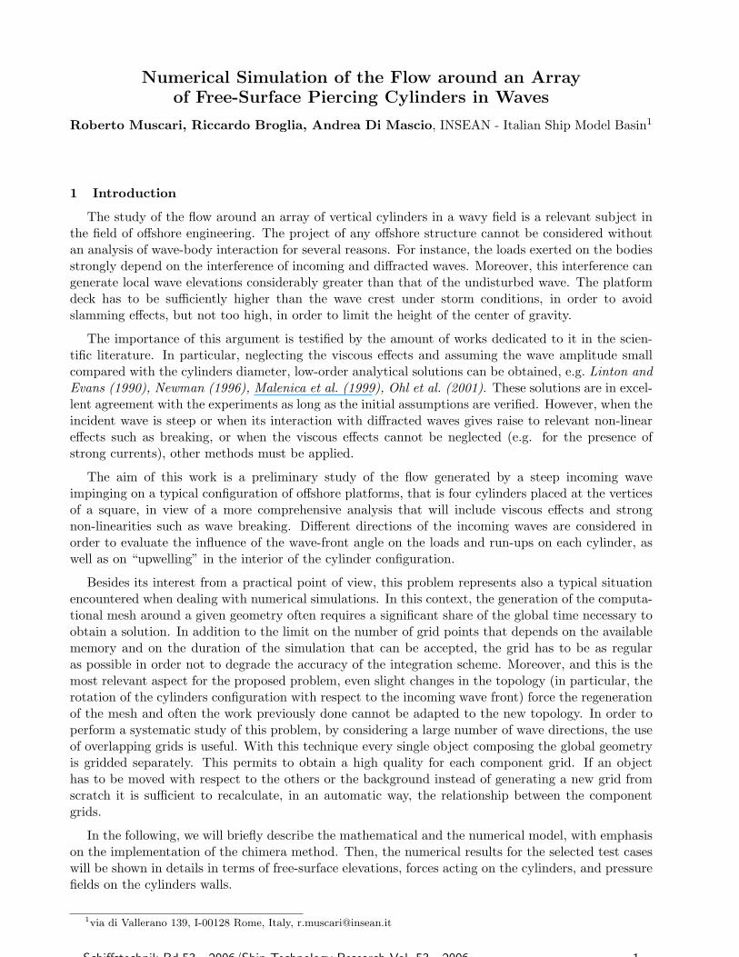
The described method was used to study the problem of the flow generated by an incoming waveimpinging on four vertical surface-piercing cylinders arranged at the vertices of a square, Fig.1. Alllengths are non-dimensionalized by the diameter of the cylinders d. The identification number foreach body and the direction of the incoming wave are indicated in Fig.1. The side of the square thatcircumscribes the cylinders is L = 4, the cylinders height is H = 3 and their immersion, with thefree-surface at rest, is D = 2.4. At the inflow the velocity field generated by the monochromatic wavein Eq.(1) is enforced. In particular, amplitude A = 0.05 and wave length λ = 4 (i.e. equal to the sideof the circumscribing square).
√gd is used as reference velocity, with g = 9.81 m/s2. Thus the Froude
number is equal to 1. The wave period T follows from the dispersion relation to T =√2πλ = 5.01.
The bottom of the physical domain is placed at z = −5, in order to have no influence on the wavepropagation.
Schiffstechnik Bd.53 - 2006/Ship Technology Research Vol. 53 - 2006 3
x
z
-5 -4 -3 -2 -1 0 1 2 3 4 5-5
-4
-3
-2
-1
0
1
L=4
#1#1#1
#4
#3
#2
β=00
β=45 0
β=30 0
x
y
-5 -4 -3 -2 -1 0 1 2 3 4 5-5
-4
-3
-2
-1
0
1
2
3
4
5
Fig.1: Numerical experiment set-up Fig.2: Detail of grid around each cylinder
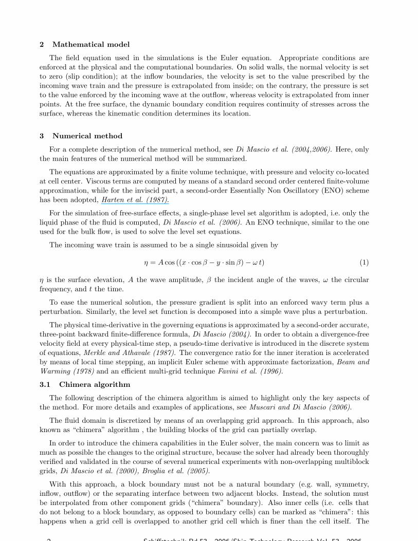
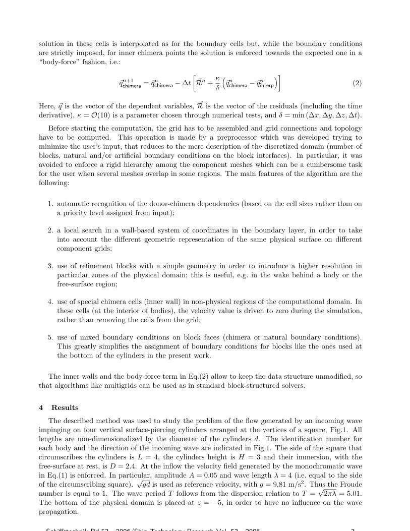
The computational mesh, Figs.2 and 3, was generated exploiting the chimera capabilities of the Eulersolver. It was composed by 10 component grids: the first grid covers the whole physical domain, thegrid is a refinement grid that resolves the free-surface region around the bodies; two grids are usedaround each cylinder, one fitted around the side and one placed at the bottom. In total, the meshhad 250000 cells, which is relatively coarse. As a consequence, the wave propagation across the field isrepresented sufficiently good when the direction is aligned with the background and refinement meshes(the first two blocks of the overlapping grid) but the quality degrades when the direction is rotatedwith respect to the grid lines. For this reason, the different wave headings are considered by rotatingthe last 8 blocks (the body-fitted ones) around the center of the domain, so that the direction of thewave motion remains parallel to the background and refinement meshes, Fig.4. The incident anglesβ = 0◦, 30◦, and 45◦ were analyzed.
Fig.3: Ten overlapping grids Fig.4: Rotation of body-fitted blocks
4.1 Incident angle β = 0◦
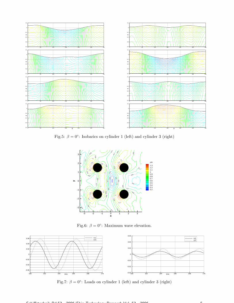
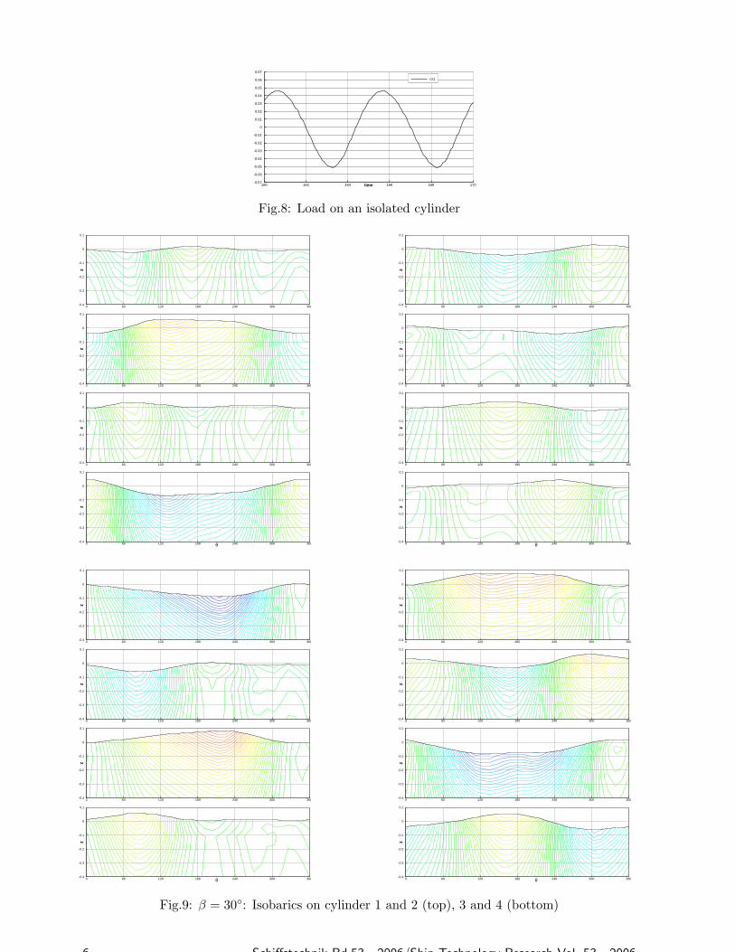
For this wave heading the flow field is symmetric around the x-axis. Hence, only the pressure fieldsand the loads for cylinders 1 and 3 will be reported. Fig.5 shows the pressure on the upper part ofthe cylinders at four different instants with time interval equal to T/4. The angle θ in abscissa isthe measured counter-clockwise starting from the lee side. The pressure distribution is not symmetricaround θ = 180◦ because of the diffraction from cylinders 2 and 4. The run-up on cylinder 3 is about50% higher than the linear wave amplitude (A in Eq.(1)) enforced at the inflow and only slightlyhigher than that on cylinder 1 (the “sheltered” one). In order to evaluate not only the run-up on thesurface of the cylinders but also the upwelling in the region encompassed by the bodies, Fig.6 showsthe maximum elevation reached during one period by the free-surface divided by the incoming waveamplitude A. In particular, the run-up on cylinder 3 (and 4) already detected in Fig.5 extends awayfrom the coat and actually involves a small area in front of the cylinder(s). A weak upwelling (between10% and 20% of A) appears behind the two foremost cylinders 3 and 4. At the opposite extremum,near the center of the configuration there is a zone where the waves interaction is destructive so thatthe local free-surface elevation never exceeds 20% of the incoming wave amplitude.
4 Schiffstechnik Bd.53 - 2006/Ship Technology Research Vol. 53 - 2006
z
0 60 120 180 240 300 360-0.4
-0.3
-0.2
-0.1
0
0.1
z
0 60 120 180 240 300 360-0.4
-0.3
-0.2
-0.1
0
0.1
z
0 60 120 180 240 300 360-0.4
-0.3
-0.2
-0.1
0
0.1
θ
z
0 60 120 180 240 300 360-0.4
-0.3
-0.2
-0.1
0
0.1
θz
0 60 120 180 240 300 360-0.4
-0.3
-0.2
-0.1
0
0.1
z
0 60 120 180 240 300 360-0.4
-0.3
-0.2
-0.1
0
0.1
z
0 60 120 180 240 300 360-0.4
-0.3
-0.2
-0.1
0
0.1
z
0 60 120 180 240 300 360-0.4
-0.3
-0.2
-0.1
0
0.1
Fig.5: β = 0◦: Isobarics on cylinder 1 (left) and cylinder 3 (right)
0.2
0.2
0.3
0.3
0.3
0.3
0.4
0.4
0.4
0.5
0.5
0.5
0.5
0.6
0.6
0.6
0.6
0.7
0.7
0.7
0.7
0.7
0.7
0.7
0.7
0.7
0.7
0.7
0.8
0.8
0.8
0 .8
0.8
0.8
0.8
0.8
0.8
0.8
0.8
0.8
0.8
0.9
0.9
0.9
0.9
0.9
0.9
0.9
0.9
0.9
1
1
1
1
1
1
1
1
1.1
1.1
1.1
1.1
1.2
1.2
1.2
1.3
0.5
1.1
1.2
0.8
0.91
1.1
x
y
-3 -2 -1 0 1 2 3
-3
-2
-1
0
1
2
3
z/A
1.31.21.110.90.80.70.60.50.40.30.2
Fig.6: β = 0◦: Maximum wave elevation.
time160 162 164 166 168 170
-0.06
-0.04
-0.02
0
0.02
0.04
0.06 cx1cx3
time160 162 164 166 168 170-0.03
-0.02
-0.01
0
0.01
0.02
0.03
cy1cy3
Fig.7: β = 0◦: Loads on cylinder 1 (left) and cylinder 3 (right)
Schiffstechnik Bd.53 - 2006/Ship Technology Research Vol. 53 - 2006 5
time160 162 164 166 168 170-0.07
-0.06
-0.05
-0.04
-0.03
-0.02
-0.01
0
0.01
0.02
0.03
0.04
0.05
0.06
0.07
cx1
Fig.8: Load on an isolated cylinder
z
0 60 120 180 240 300 360-0.4
-0.3
-0.2
-0.1
0
0.1
z
0 60 120 180 240 300 360-0.4
-0.3
-0.2
-0.1
0
0.1
z
0 60 120 180 240 300 360-0.4
-0.3
-0.2
-0.1
0
0.1
θ
z
0 60 120 180 240 300 360-0.4
-0.3
-0.2
-0.1
0
0.1
θ
z
0 60 120 180 240 300 360-0.4
-0.3
-0.2
-0.1
0
0.1
z
0 60 120 180 240 300 360-0.4
-0.3
-0.2
-0.1
0
0.1
z
0 60 120 180 240 300 360-0.4
-0.3
-0.2
-0.1
0
0.1
z
0 60 120 180 240 300 360-0.4
-0.3
-0.2
-0.1
0
0.1
θ
z
0 60 120 180 240 300 360-0.4
-0.3
-0.2
-0.1
0
0.1
z
0 60 120 180 240 300 360-0.4
-0.3
-0.2
-0.1
0
0.1
z
0 60 120 180 240 300 360-0.4
-0.3
-0.2
-0.1
0
0.1
z
0 60 120 180 240 300 360-0.4
-0.3
-0.2
-0.1
0
0.1
z
0 60 120 180 240 300 360-0.4
-0.3
-0.2
-0.1
0
0.1
z
0 60 120 180 240 300 360-0.4
-0.3
-0.2
-0.1
0
0.1
z
0 60 120 180 240 300 360-0.4
-0.3
-0.2
-0.1
0
0.1
θ
z
0 60 120 180 240 300 360-0.4
-0.3
-0.2
-0.1
0
0.1
Fig.9: β = 30◦: Isobarics on cylinder 1 and 2 (top), 3 and 4 (bottom)
6 Schiffstechnik Bd.53 - 2006/Ship Technology Research Vol. 53 - 2006
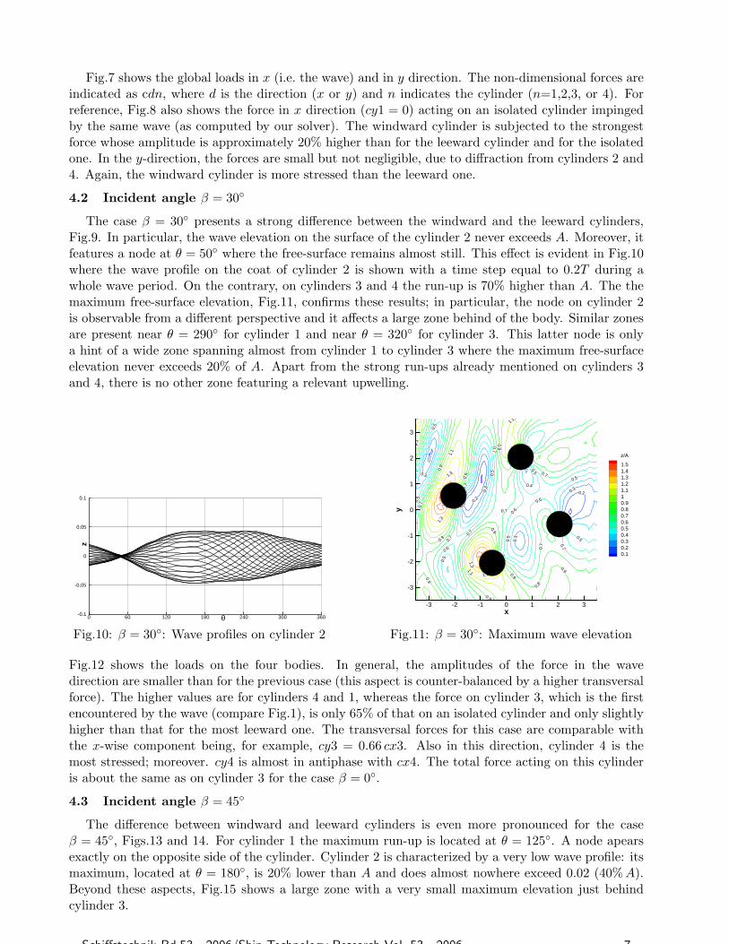
Fig.7 shows the global loads in x (i.e. the wave) and in y direction. The non-dimensional forces areindicated as cdn, where d is the direction (x or y) and n indicates the cylinder (n=1,2,3, or 4). Forreference, Fig.8 also shows the force in x direction (cy1 = 0) acting on an isolated cylinder impingedby the same wave (as computed by our solver). The windward cylinder is subjected to the strongestforce whose amplitude is approximately 20% higher than for the leeward cylinder and for the isolatedone. In the y-direction, the forces are small but not negligible, due to diffraction from cylinders 2 and4. Again, the windward cylinder is more stressed than the leeward one.
4.2 Incident angle β = 30◦
The case β = 30◦ presents a strong difference between the windward and the leeward cylinders,Fig.9. In particular, the wave elevation on the surface of the cylinder 2 never exceeds A. Moreover, itfeatures a node at θ = 50◦ where the free-surface remains almost still. This effect is evident in Fig.10where the wave profile on the coat of cylinder 2 is shown with a time step equal to 0.2T during awhole wave period. On the contrary, on cylinders 3 and 4 the run-up is 70% higher than A. The themaximum free-surface elevation, Fig.11, confirms these results; in particular, the node on cylinder 2is observable from a different perspective and it affects a large zone behind of the body. Similar zonesare present near θ = 290◦ for cylinder 1 and near θ = 320◦ for cylinder 3. This latter node is onlya hint of a wide zone spanning almost from cylinder 1 to cylinder 3 where the maximum free-surfaceelevation never exceeds 20% of A. Apart from the strong run-ups already mentioned on cylinders 3and 4, there is no other zone featuring a relevant upwelling.
θ
z
0 60 120 180 240 300 360-0.1
-0.05
0
0.05
0.1
Fig.10: β = 30◦: Wave profiles on cylinder 2
0.3
0.3
0.3
0.3
0.3
0.3
0.5 0.5
0.5
0.5
0.5 0.
5
0.5 0.5
0.7
0.7
0.7
0.7
0.7
0.7
0.70.7
0.7
0.9
0.9
0.9
0.9
0.9
0.9
0.9
0.9
0.91.1
1.1
1.1
1.1
1.1
1.1
1.3
1.3
1.3
0.2
0.6
0.4
0.60.7
0.2
0.6
0.5
0.8
x
y
-3 -2 -1 0 1 2 3
-3
-2
-1
0
1
2
3
z/A
1.51.41.31.21.110.90.80.70.60.50.40.30.20.1
Fig.11: β = 30◦: Maximum wave elevation
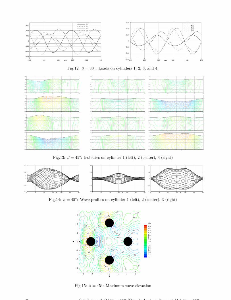
Fig.12 shows the loads on the four bodies. In general, the amplitudes of the force in the wavedirection are smaller than for the previous case (this aspect is counter-balanced by a higher transversalforce). The higher values are for cylinders 4 and 1, whereas the force on cylinder 3, which is the firstencountered by the wave (compare Fig.1), is only 65% of that on an isolated cylinder and only slightlyhigher than that for the most leeward one. The transversal forces for this case are comparable withthe x-wise component being, for example, cy3 = 0.66 cx3. Also in this direction, cylinder 4 is themost stressed; moreover. cy4 is almost in antiphase with cx4. The total force acting on this cylinderis about the same as on cylinder 3 for the case β = 0◦.
4.3 Incident angle β = 45◦
The difference between windward and leeward cylinders is even more pronounced for the caseβ = 45◦, Figs.13 and 14. For cylinder 1 the maximum run-up is located at θ = 125◦. A node apearsexactly on the opposite side of the cylinder. Cylinder 2 is characterized by a very low wave profile: itsmaximum, located at θ = 180◦, is 20% lower than A and does almost nowhere exceed 0.02 (40%A).Beyond these aspects, Fig.15 shows a large zone with a very small maximum elevation just behindcylinder 3.
Schiffstechnik Bd.53 - 2006/Ship Technology Research Vol. 53 - 2006 7
time160 162 164 166 168 170
-0.06
-0.04
-0.02
0
0.02
0.04
0.06 cx1cx2cx3cx4
time160 162 164 166 168 170-0.03
-0.02
-0.01
0
0.01
0.02
0.03
cy1cy2cy3cy4
Fig.12: β = 30◦: Loads on cylinders 1, 2, 3, and 4.
z
0 60 120 180 240 300 360-0.4
-0.3
-0.2
-0.1
0
0.1
z
0 60 120 180 240 300 360-0.4
-0.3
-0.2
-0.1
0
0.1
z
0 60 120 180 240 300 360-0.4
-0.3
-0.2
-0.1
0
0.1
θ
z
0 60 120 180 240 300 360-0.4
-0.3
-0.2
-0.1
0
0.1
θ
z
0 60 120 180 240 300 360-0.4
-0.3
-0.2
-0.1
0
0.1
z
0 60 120 180 240 300 360-0.4
-0.3
-0.2
-0.1
0
0.1
z
0 60 120 180 240 300 360-0.4
-0.3
-0.2
-0.1
0
0.1
z
0 60 120 180 240 300 360-0.4
-0.3
-0.2
-0.1
0
0.1
z
0 60 120 180 240 300 360-0.4
-0.3
-0.2
-0.1
0
0.1
z
0 60 120 180 240 300 360-0.4
-0.3
-0.2
-0.1
0
0.1
z
0 60 120 180 240 300 360-0.4
-0.3
-0.2
-0.1
0
0.1
θz
0 60 120 180 240 300 360-0.4
-0.3
-0.2
-0.1
0
0.1
Fig.13: β = 45◦: Isobarics on cylinder 1 (left), 2 (center), 3 (right)
θ
z
0 60 120 180 240 300 360-0.1
-0.05
0
0.05
0.1
θ
z
0 60 120 180 240 300 360-0.1
-0.05
0
0.05
0.1
θ
z
0 60 120 180 240 300 360-0.1
-0.05
0
0.05
0.1
Fig.14: β = 45◦: Wave profiles on cylinder 1 (left), 2 (center), 3 (right)
0.3
0.3
0.5
0.5
0.5
0.5
0.5
0.5
0.5
0.7
0.7
0.7
0.7
0.7
0.7
0.7
0.7
0.7
0.7
0.7
0.9
0.9
0.9
0.9
0.9
0.9
0.9
0.9
0.9
1.1
1.1
1.3
1.3
1.3
0.30.4
0.5
0.60.7
0.8
0.2
0.3
0.4
0.4
0.6
0.40.3
1.2
1
1.1
1.3
0.8
1.4
1.4
x
y
-3 -2 -1 0 1 2 3
-3
-2
-1
0
1
2
3
z/A
1.51.41.31.21.110.90.80.70.60.50.40.30.20.1
Fig.15: β = 45◦: Maximum wave elevation
8 Schiffstechnik Bd.53 - 2006/Ship Technology Research Vol. 53 - 2006
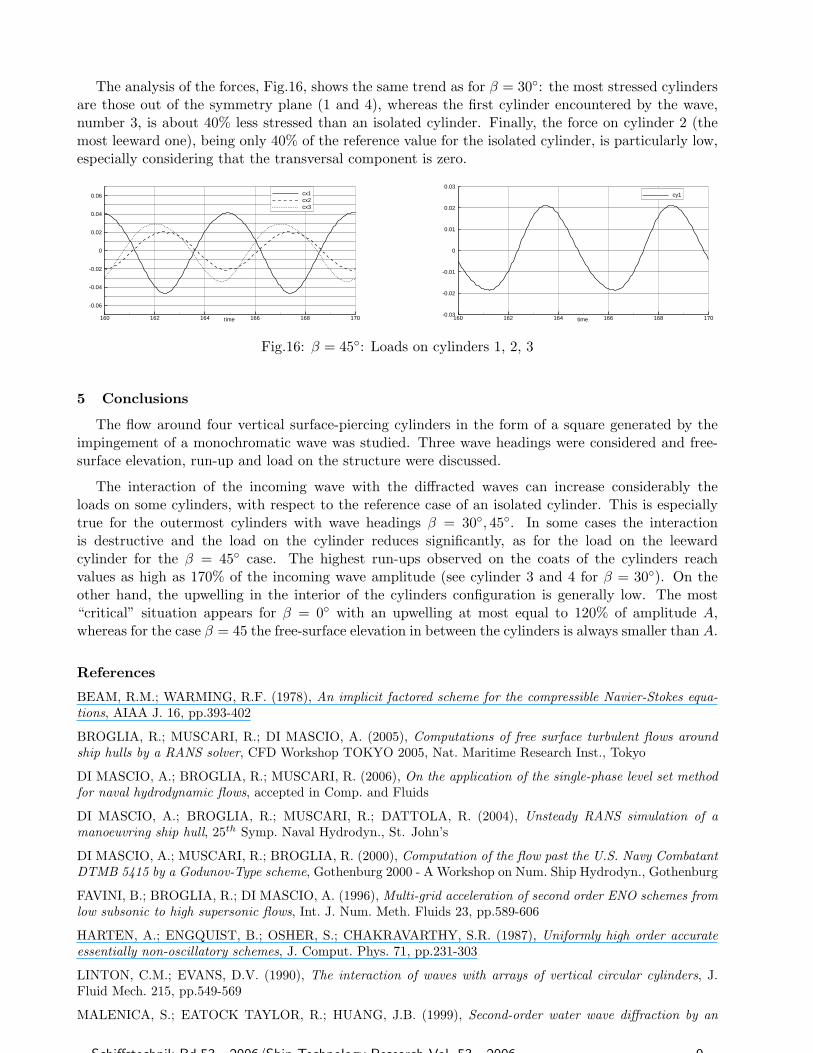
The analysis of the forces, Fig.16, shows the same trend as for β = 30◦: the most stressed cylindersare those out of the symmetry plane (1 and 4), whereas the first cylinder encountered by the wave,number 3, is about 40% less stressed than an isolated cylinder. Finally, the force on cylinder 2 (themost leeward one), being only 40% of the reference value for the isolated cylinder, is particularly low,especially considering that the transversal component is zero.
time160 162 164 166 168 170
-0.06
-0.04
-0.02
0
0.02
0.04
0.06 cx1cx2cx3
time160 162 164 166 168 170-0.03
-0.02
-0.01
0
0.01
0.02
0.03
cy1
Fig.16: β = 45◦: Loads on cylinders 1, 2, 3
5 Conclusions
The flow around four vertical surface-piercing cylinders in the form of a square generated by theimpingement of a monochromatic wave was studied. Three wave headings were considered and free-surface elevation, run-up and load on the structure were discussed.
The interaction of the incoming wave with the diffracted waves can increase considerably theloads on some cylinders, with respect to the reference case of an isolated cylinder. This is especiallytrue for the outermost cylinders with wave headings β = 30◦, 45◦. In some cases the interactionis destructive and the load on the cylinder reduces significantly, as for the load on the leewardcylinder for the β = 45◦ case. The highest run-ups observed on the coats of the cylinders reachvalues as high as 170% of the incoming wave amplitude (see cylinder 3 and 4 for β = 30◦). On theother hand, the upwelling in the interior of the cylinders configuration is generally low. The most“critical” situation appears for β = 0◦ with an upwelling at most equal to 120% of amplitude A,whereas for the case β = 45 the free-surface elevation in between the cylinders is always smaller than A.
References
BEAM, R.M.; WARMING, R.F. (1978), An implicit factored scheme for the compressible Navier-Stokes equa-tions, AIAA J. 16, pp.393-402
BROGLIA, R.; MUSCARI, R.; DI MASCIO, A. (2005), Computations of free surface turbulent flows aroundship hulls by a RANS solver, CFD Workshop TOKYO 2005, Nat. Maritime Research Inst., Tokyo
DI MASCIO, A.; BROGLIA, R.; MUSCARI, R. (2006), On the application of the single-phase level set methodfor naval hydrodynamic flows, accepted in Comp. and Fluids
DI MASCIO, A.; BROGLIA, R.; MUSCARI, R.; DATTOLA, R. (2004), Unsteady RANS simulation of amanoeuvring ship hull, 25th Symp. Naval Hydrodyn., St. John’s
DI MASCIO, A.; MUSCARI, R.; BROGLIA, R. (2000), Computation of the flow past the U.S. Navy CombatantDTMB 5415 by a Godunov-Type scheme, Gothenburg 2000 - A Workshop on Num. Ship Hydrodyn., Gothenburg
FAVINI, B.; BROGLIA, R.; DI MASCIO, A. (1996), Multi-grid acceleration of second order ENO schemes fromlow subsonic to high supersonic flows, Int. J. Num. Meth. Fluids 23, pp.589-606
HARTEN, A.; ENGQUIST, B.; OSHER, S.; CHAKRAVARTHY, S.R. (1987), Uniformly high order accurateessentially non-oscillatory schemes, J. Comput. Phys. 71, pp.231-303
LINTON, C.M.; EVANS, D.V. (1990), The interaction of waves with arrays of vertical circular cylinders, J.Fluid Mech. 215, pp.549-569
MALENICA, S.; EATOCK TAYLOR, R.; HUANG, J.B. (1999), Second-order water wave diffraction by an
Schiffstechnik Bd.53 - 2006/Ship Technology Research Vol. 53 - 2006 9
array of vertical cylinders, J. Fluid Mech. 390, pp.349-373
MERKLE, C.L.; ATHAVALE, M. (1987), Time-accurate unsteady incompressible flow algorithm based on arti-ficial compressibility, AIAA Paper 87-1137
MUSCARI, R.; Di MASCIO, A. (2005), Simulation of the flow around complex hull geometries by an overlappinggrid approach, 5th Osaka Coll. Advanced Research on Ship Viscous Flow and Hull Form Design by EFD andCFD Approaches, Osaka
NEWMAN, J.N. (1996), The second-order wave force on a vertical cylinder, J. Fluid Mech. 320, pp.417-443
OHL, C.O.G.; EATOCK TAYLOR, R.; TAYLOR, P.H.; BORTHWICK, A.G.L. (2001), Water wave diffractionby a cylinder array. Part 1: Regular waves, J. Fluid Mech. 442, pp.1-32
10 Schiffstechnik Bd.53 - 2006/Ship Technology Research Vol. 53 - 2006
Related Documents