China Ocean Eng., Vol. 30, No. 1, pp. 33 – 46 © 2016 Chinese Ocean Engineering Society and Springer-Verlag Berlin Heidelberg DOI 10.1007/s13344-016-0002-1, ISSN 0890-5487 Numerical Simulation of Installation Process and Uplift Resistance for An Integrated Suction Foundation in Deep Ocean * LI Ying (李 英), YANG Shu-geng (杨树耕) 1 and YU Shu-ming (于书铭) State Key Laboratory of Hydraulic Engineering Simulation and Safety, Tianjin University, Tianjin 300072, China (Received 13 September 2013; received revised form 15 May 2014; accepted 25 July 2014) ABSTRACT A concept design, named integrated suction foundation, is proposed for a tension leg platform (TLP) in deep ocean. The most important improvement in comparing with the traditional one is that a pressure-resistant storage module is designed. It utilizes the high hydrostatic pressure in deep ocean to drive water into the module to generate negative pressure for bucket suction. This work aims to further approve the feasibility of the concept design in the aspect of penetration installation and the uplift force in-place. Seepage is generated during suction penetration, and can have both positive and negative effects on penetration process. To study the effect of seepage on the penetration process of the integrated suction foundation, finite element analysis (FEA) is carried out in this work. In particular, an improved methodology to calculate the penetration resistance is proposed for the integrated suction foundation with respect to the reduction factor of penetration resistance. The maximum allowable negative pressure during suction penetration is calculated with the critical hydraulic gradient method through FEA. The simulation results of the penetration process show that the integrated suction foundation can be installed safely. Moreover, the uplift resistance of the integrated suction foundation is calculated and the feasibility of the integrated suction foundation working on-site is verified. In all, the analysis in this work further approves the feasibility of the integrated suction foundation for TLPs in deep ocean applications. Key words: integrated suction foundation; penetration resistance; TLP; finite element analysis; deep ocean 1. Introduction The development of suction foundation can be traced back to 1958 when Mackereth used the suction bucket to take soil sample in a soft lake. Subsequently Norwegian Geotechnical Institute (NGI) had a successful penetration test for suction bucket to the seabed. The first suction foundation for offshore platform in the world was installed in the North Sea with the water depth of 70 m (Tjelta, 1995). Meanwhile, Bye et al. (1995) suggested that suction installed skirted plate foundations (buckets) may not only be competitive alternatives to piles, but also a complementary foundation solution both for non-cohesive and cohesive soils. Wang et al. (2006) presented the experimental investigation of the response of suction bucket foundation in fine sand layer under horizontal dynamic loads. Zhang et al. (2007) presented the results of a series of centrifuge model tests, which were performed to study the * This work was financially supported by the National Basic Key Research Program of China (973 Program, Grant No. 2014CB46804) and the Tianjin Research Program of Application Foundation and Advanced Technology (Grant No. 15JCYBJC21700). 1 Corresponding author. E-mail: [email protected]

Welcome message from author
This document is posted to help you gain knowledge. Please leave a comment to let me know what you think about it! Share it to your friends and learn new things together.
Transcript

China Ocean Eng., Vol. 30, No. 1, pp. 33 – 46 © 2016 Chinese Ocean Engineering Society and Springer-Verlag Berlin Heidelberg DOI 10.1007/s13344-016-0002-1, ISSN 0890-5487
Numerical Simulation of Installation Process and Uplift Resistance for An
Integrated Suction Foundation in Deep Ocean*
LI Ying (李 英), YANG Shu-geng (杨树耕)1 and YU Shu-ming (于书铭)
State Key Laboratory of Hydraulic Engineering Simulation and Safety, Tianjin University,
Tianjin 300072, China
(Received 13 September 2013; received revised form 15 May 2014; accepted 25 July 2014)
ABSTRACT
A concept design, named integrated suction foundation, is proposed for a tension leg platform (TLP) in deep ocean.
The most important improvement in comparing with the traditional one is that a pressure-resistant storage module is
designed. It utilizes the high hydrostatic pressure in deep ocean to drive water into the module to generate negative
pressure for bucket suction. This work aims to further approve the feasibility of the concept design in the aspect of
penetration installation and the uplift force in-place. Seepage is generated during suction penetration, and can have both
positive and negative effects on penetration process. To study the effect of seepage on the penetration process of the
integrated suction foundation, finite element analysis (FEA) is carried out in this work. In particular, an improved
methodology to calculate the penetration resistance is proposed for the integrated suction foundation with respect to the
reduction factor of penetration resistance. The maximum allowable negative pressure during suction penetration is
calculated with the critical hydraulic gradient method through FEA. The simulation results of the penetration process
show that the integrated suction foundation can be installed safely. Moreover, the uplift resistance of the integrated
suction foundation is calculated and the feasibility of the integrated suction foundation working on-site is verified. In all,
the analysis in this work further approves the feasibility of the integrated suction foundation for TLPs in deep ocean
applications.
Key words: integrated suction foundation; penetration resistance; TLP; finite element analysis; deep ocean
1. Introduction
The development of suction foundation can be traced back to 1958 when Mackereth used the
suction bucket to take soil sample in a soft lake. Subsequently Norwegian Geotechnical Institute (NGI)
had a successful penetration test for suction bucket to the seabed. The first suction foundation for
offshore platform in the world was installed in the North Sea with the water depth of 70 m (Tjelta,
1995). Meanwhile, Bye et al. (1995) suggested that suction installed skirted plate foundations (buckets)
may not only be competitive alternatives to piles, but also a complementary foundation solution both
for non-cohesive and cohesive soils. Wang et al. (2006) presented the experimental investigation of the
response of suction bucket foundation in fine sand layer under horizontal dynamic loads. Zhang et al.
(2007) presented the results of a series of centrifuge model tests, which were performed to study the
* This work was financially supported by the National Basic Key Research Program of China (973 Program, Grant No. 2014CB46804)
and the Tianjin Research Program of Application Foundation and Advanced Technology (Grant No. 15JCYBJC21700).
1 Corresponding author. E-mail: [email protected]

LI Ying et al. / China Ocean Eng., 30(1), 2016, 33 – 46 34
behavior of suction bucket foundations for a tension leg platform (TLP) in the Bohai Bay, China.
In addition to the experimental studies described above, the finite element method has been used
widely by previous researchers for the analyses of suction bucket foundations. Templeton (2002)
presented the role of finite element analysis (FEA) in the design of suction foundations for offshore
production and exploration. Sparrevik (2002) discussed different design and installation aspects such
as anchor geometry, load response, equipment and marine operations for soil and loading conditions
representative for deepwater field developments around the world. Zdravkovic et al. (2001) performed
parametric studies to provide benchmarks for results of other calculation methods. Zhang et al. (2004)
simulated the seepage field generated by suction penetration numerically with a finite element method
and discussed the allowable suction pressures with various penetration depths of a bucket foundation
into sea floor. Clukey and Morrison (1993) performed centrifuge tests to investigate the behavior of
suction piles in normally consolidated clays and carried out FEA. Fakharian and Soltanmonhammadlou
(2005) simulated the process of pile penetration under self-weight and negative pressure for a TLP in
the water depth of 1000 m using the software PLAXIS. Maniar and Tassoulas (2003) used the
experimental data to set up finite element model so as to analyze the soil consolidation after
installation for suction caisson.
The uplift resistance of soils is normally associated with the design of foundations for structures
where an adequate margin of safety is required against failure. In practice, there are cases of
penetration failure during suction installation and uplifting resistance failure in operational scenario.
Therefore, it is pressing need to understand and control penetration process for suction bucket
foundations quantitatively. During the suction penetration installation of bucket foundations, seepage
field is generated by the flow from the soil surface outside toward the soil surface inside the buckets
due to the water head difference. Engineering tests from Bye et al. (1995) and Tjelta (1995) suggested
that seepage reduces the penetration resistance and it also restricts the driven force during suction
penetration. Owing to the seepage generated during penetration, the effective force of soil around
bucket foundations is changed and the penetration resistance is reduced, which benefits the process of
suction penetration. On the other hand, seepage restricts the penetration force because a large amount
of seepage causes loss of soil stability, which induces deformation of soil seepage and even piping or
flowing soil. This damages the integrity of bucket foundations and subsequently leads to the failure of
suction penetration of bucket foundations. It is obvious that the seepage field generated during
penetration is crucial to the installation of the suction bucket foundation. Therefore, the quantified
seepage investigation is necessary for understanding mechanism of penetration process for the bucket
suction foundation so as for the successful installation.
With the exploration of oil and gas in much deeper ocean in nowadays, tension leg platforms
(TLPs) become one of the widely used constructions. However, the traditional suction bucket
foundation is limited by the pump capacity for the application of bucket penetration for TLPs in deep
ocean. Instead, Li et al. (2012) proposed an advanced concept design of suction foundations based on
the traditional suction bucket foundations. The concept design is for the foundations of TLPs in water
depth of 1000 m in the South China Sea, named the integrated suction foundation.
The application in deep ocean of the concept design is proved to be feasible in terms of structure

LI Ying et al. / China Ocean Eng., 30(1), 2016, 33 – 46 35
integrity by Li et al. (2012). Therefore, a further study for the integrated suction foundation is centered
on influences of seepage on the foundation stability. This work has covered both suction penetration
and uplift resistance aspects. In suction penetration study, the penetration process of the integrated
suction foundation in the soil of sand is simulated by taking into account of the seepage field generated
during suction penetration. Moreover, the uplift resistance of the integrated suction foundation is
investigated to ensure that it works safely on-site. In this paper, the theory and methodology to carry
out the study for suction bucket foundation is described in the first instance. Subsequently, the results
of the case study for the integrated suction foundation are presented. The work ends with conclusions
and discussions.
2. Theoretical Background and Methodology of Penetration Resistance
and Uplift Resistance
An overview of the numerical technology of simulating the penetration resistance and the uplift
resistance for the integrated suction foundation is presented in this section. In Section 2.1, the theory of
seepage is applied to explain the seepage issue generated during suction installation for bucket
foundations. The methodology of simulating penetration resistance is presented for bucket foundations
in Section 2.2. In the following, an improved methodology of estimating the factors of friction
resistance is proposed to account for the seepage effect on the suction penetration of suction bucket
foundations. In Section 2.4, the methodology of calculating the allowable negative pressure for bucket
penetration is described. Finally, in Section 2.5, FEA of the uplift resistance of bucket foundations is
presented.
2.1 Numerical Techniques of Seepage Generated in Suction Penetration
To simulate the penetration resistance for suction foundation in the soil of sand, the seepage of
soil inside and outside of suction bucket foundations must be considered, since the seepage field is
generated during the process of suction penetration. For numerical simulation, the process of bucket
penetration can be divided into small time steps, and the seepage field can be regarded as being in
steady state within each small time step even though penetration is a dynamic hydraulic process. Since
suction bucket foundations are axisymmetrical, the seepage field around bucket foundations is an
axisymmetrical steady field in conformity with Darcy’s law. The water head distribution of the seepage
field satisfies the axisymmetrical Laplace equation, as shown in Eq. (1). 2 2
h v2
10
u u uC C
r r r z
. (1)
Moreover, the water head distribution at the mudeline of the inside and outside suction bucket
foundations conforms to the first kind of boundary condition. It is given as follows:
1( , )u f r z
. (2)
The water head of the seepage field also satisfies the flux boundary condition at the location of
both inside and outside bucket wall in contact with soil, defined as the second kind of boundary
condition. It is given as follows:

LI Ying et al. / China Ocean Eng., 30(1), 2016, 33 – 46 36
2
( , )u
f r zr
, (3)
In Eqs. (1)(3), u is the water head function, r and z are the spatial cylindrical coordinates system; Ch
is the permeability coefficient along the radial direction; Cv is the permeability coefficient along the
vertical direction; 1 and 2 are curved surface boundaries.
Owing to the complex geometric boundary conditions, it is difficult to obtain the analytical
solution for the equations above. FEA is applied to include the complex boundaries and non-uniform
soil layer conditions. In FEA, the continuous seepage field is divided into finite elements and the water
head distribution on the element is expressed using interpolation function. Since the water head
boundary condition is included in the equations, the water head satisfies the Laplace equation and the
analytical solution of boundaries.
2.2 Methodology of Penetration Resistance of Bucket Suction Penetration
The penetration resistance of suction penetration has determinant effect on the successful
installation for suction bucket foundation of TLPs. During suction installation for bucket foundations,
the applied negative pressure is related to the penetration resistance. Their relationship is the key factor
to determine the dimensions of suction bucket foundations. This suggests the significance of
simulating the penetration resistance with appropriate methodology for suction installation. In this
work, the penetration resistance is calculated on the basis of the water head distribution that is
simulated from the seepage field generated during suction installation.
During bucket penetration, the effective force in the surrounding soil of suction bucket
foundations changes with the generation of seepage field. Along the outside of the bucket wall, the
seepage direction is downward, and the effective force of the soil increases. The effective force outside
the bucket wall is calculated as:
0 outw .
H L hZ Z
L
(4)
For the soil inside suction bucket foundations, the seepage direction is upward so that the
effective force of the soil decreases. The effective force inside suction bucket foundations is given as:
in 0w .
h hZ Z
L
(5)
The effective force of soil around the end of bucket foundations is also changed due to seepage
and is calculated as:
out tip
w .h h
L Lt
(6)
In Eqs. (4)(6), ’ is the effective force of soil; w is the density of water, ’ is the submerged weight of
soil; L is the distance from the mudline to the bottom of suction bucket foundations; t is the thickness
of suction bucket foundations; H0 is the water head at the mudline out of suction bucket foundations; h0
is the absolute pressure inside suction bucket foundations; z is the depth from the mudline to the
calculation point. hout is the water head of the soil outside suction bucket foundations in a given point;

LI Ying et al. / China Ocean Eng., 30(1), 2016, 33 – 46 37
hin is the water head of the soil inside suction bucket foundations at a given point; htip is the water head
of the soil at the end of suction bucket foundations.
For the seepage field around suction bucket foundations, the wall of inside and outside suction
bucket foundations is the first flow line in theory. The seepage in the surrounding area of the first flow
line can be taken as one dimensional flow approximately. With the effective force in the soil to replace
the effective pressure on the surface of suction bucket foundations, the friction force between suction
bucket foundations and soil as well as the end resistance of suction bucket foundations are calculated.
The friction resistance of the outside wall of suction bucket foundations is given as:
0 outout out 0 w
0
π tg d .L H L h
f D K z z zL
(7)
The friction resistance of the inside wall of suction bucket foundations is presented as:
in 0in in 0 w
0
π tg dL h H
f D K z z zL
. (8)
The end resistance of suction bucket foundations can be calculated as:
out tip2 2
out in w
π
4 q
h hR D D L L N
t
. (9)
In the equations above, K0 is the passive resistance of soil; Nq is the friction coefficient; Dout and
Din are the outer diameter and inner diameter of suction bucket foundation, respectively; is the
friction angle between the bucket foundation and soil around.
At the stage of suction penetration, the sum of the wall friction resistance of inside and outside
suction bucket foundation in addition to the end resistance of suction bucket foundations is the total
penetration resistance. It is given in Eq. (10):
out inf f f R . (10)
The total penetration force under suction penetration consists of two components. They are the
submerged weight of suction bucket foundations and the force due to the pressure difference between
the outside and the inside suction bucket foundations.
2.3 Improved Penetration Resistance Equations Under Suction Penetration
To investigate the influence of seepage on the penetration resistance in the soil of sand for suction
bucket foundations, Shell Offshore Research introduces a reduction factor to calculate the penetration
resistance. It can be calculated as:
f p ch
0
π 2 dh
R D k f z k q t
, (11)
where D is the diameter of suction bucket foundations; kf is the empirical factor related to the skin
friction resistance; f is the friction resistance from the penetration experiments of the original
coordinate; h is the penetration depth; kp is the experienced factor related to qch, and qch is the average
penetration resistance in specific layer of soil; kf and kp are the reduction factors taking account of
seepage and flowing soil and are usually determined from large scale model test on site, which is

LI Ying et al. / China Ocean Eng., 30(1), 2016, 33 – 46 38
difficult to obtain generally.
It can be seen from the penetration resistance equation given above that the influence of seepage
mechanism on the friction resistance of the inside suction bucket foundation and that of the outside
suction bucket foundation is different. There are a few reasons accounting for the difference. Firstly,
the effective force in the soil outside bucket foundations increases because of the seepage, while the
effective force of the soil inside bucket foundations decreases. Secondly, the seepage distance and the
seepage volume are different for the soil inside and outside suction bucket foundations. The seepage
volume along the outside wall of suction bucket foundations is smaller than that along the inside wall
of suction bucket foundations. Thirdly, the seepage gradient is also different for the soil inside and
outside suction bucket foundations. The seepage gradient inside suction bucket foundations is large so
that the decrease of soil effective force due to seepage is large. On the other hand, the seepage gradient
outside suction bucket foundations is small so that the increase of the soil effective force due to
seepage is small. In all, the influence of seepage mechanism on the friction resistance of the inside and
outside of suction bucket foundations is different. In view of the discussions above, the methodology
from Shell Offshore Research, as given in Eq. (11), does not present the penetration resistance
accurately, since the inside and outside friction resistances of suction bucket foundation are combined
together to estimate the penetration resistance. To predict the penetration resistance more accurate, an
improved methodology of the penetration resistance under suction for bucket foundation is proposed as
follows:
out out in in p ch
0 0
π d dh h
R D k f z k f z k q t
, (12)
where kout and kin are the factors of friction resistance related to the inside and outside wall of suction
bucket foundations, respectively; and the other symbols are the same as given in Eq. (11).
It is usually difficult to separate kout and kin using model tests due to the limitation in test
methodology presently. Numerical simulation is hence an alternative to determine kout and kin. The
penetration process of suction bucket foundations is simulated using FEA and the reduction factors of
penetration resistance are calculated accordingly in this work. The friction resistance inside suction
bucket foundations and that outside suction bucket foundations as well as the penetration resistance are
calculated for various penetration depths and various negative pressures using FEA. Moreover, the
penetration resistance is calculated for the same conditions without considering seepage in the soil
during suction penetration. Subsequently, the reduction factors of the friction resistance during suction
penetration are calculated by comparing the penetration force for suction bucket foundations from FEA
with and without considering seepage in the soil.
2.4 Methodology of the Allowable Negative Pressure for Suction Penetration
2.4.1 Critical Hydraulic Gradient
Piping is the most dangerous failure of suction bucket penetrations and the critical hydraulic
gradient of piping is always smaller than that of soil flowing. The hydraulic gradient of piping is hence
considered as the critical hydraulic gradient of soil in this work. The critical hydraulic gradient of
piping shows the starting point of fine granular loss, indicating the suction bucket foundation is weak
LI Ying et al. / China Ocean Eng., 30(1), 2016, 33 – 46 39
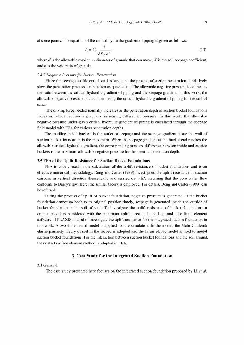
at some points. The equation of the critical hydraulic gradient of piping is given as follows:
c 342 ,
/
dJ
K n (13)
where d is the allowable maximum diameter of granule that can move, K is the soil seepage coefficient,
and n is the void ratio of granule.
2.4.2 Negative Pressure for Suction Penetration
Since the seepage coefficient of sand is large and the process of suction penetration is relatively
slow, the penetration process can be taken as quasi-static. The allowable negative pressure is defined as
the ratio between the critical hydraulic gradient of piping and the seepage gradient. In this work, the
allowable negative pressure is calculated using the critical hydraulic gradient of piping for the soil of
sand.
The driving force needed normally increases as the penetration depth of suction bucket foundations
increases, which requires a gradually increasing differential pressure. In this work, the allowable
negative pressure under given critical hydraulic gradient of piping is calculated through the seepage
field model with FEA for various penetration depths.
The mudline inside buckets is the outlet of seepage and the seepage gradient along the wall of
suction bucket foundation is the maximum. When the seepage gradient at the bucket end reaches the
allowable critical hydraulic gradient, the corresponding pressure difference between inside and outside
buckets is the maximum allowable negative pressure for the specific penetration depth.
2.5 FEA of the Uplift Resistance for Suction Bucket Foundations
FEA is widely used in the calculation of the uplift resistance of bucket foundations and is an
effective numerical methodology. Deng and Carter (1999) investigated the uplift resistance of suction
caissons in vertical direction theoretically and carried out FEA assuming that the pore water flow
conforms to Darcy’s law. Here, the similar theory is employed. For details, Deng and Carter (1999) can
be referred.
During the process of uplift of bucket foundation, negative pressure is generated. If the bucket
foundation cannot go back to its original position timely, seepage is generated inside and outside of
bucket foundation in the soil of sand. To investigate the uplift resistance of bucket foundations, a
drained model is considered with the maximum uplift force in the soil of sand. The finite element
software of PLAXIS is used to investigate the uplift resistance for the integrated suction foundation in
this work. A two-dimensional model is applied for the simulation. In the model, the Mohr-Coulomb
elastic-plasticity theory of soil in the seabed is adopted and the linear elastic model is used to model
suction bucket foundations. For the interaction between suction bucket foundations and the soil around,
the contact surface element method is adopted in FEA.
3. Case Study for the Integrated Suction Foundation
3.1 General
The case study presented here focuses on the integrated suction foundation proposed by Li et al.

LI Ying et al. / China Ocean Eng., 30(1), 2016, 33 – 46 40
(2012). The integrated suction foundation is designed for TLP in the South China Sea with the water
depth of 1000 m with the soil of sand in seabed and its configuration is illustrated in Fig. 1. The soil
properties on-site for the integrated suction foundation are given in Table 1. As shown in Fig. 1, the
four buckets of the integrated suction foundations are connected together, so that the penetration of
four buckets would happen at the same time. The diameter of bucket foundation is 12 m with the
thickness of 0.05 m, and the height of bucket foundation is 20 m. The central distance between
adjacent bucket foundations is 50 m. For more detailed dimensions of the integrated suction foundation,
it can be referred to Li et al. (2012).
Fig. 1. Configuration of the integrated suction foundation for TLP in the South China Sea (Li et al., 2012).
Table 1 Mechanical properties of the sand of soil used in this work
Submerged weight (kN/m3)
Elastic modulus (kN/m2)
Permeability coefficient in horizontal direction (cm/s)
Permeability coefficient in vertical direction (cm/s)
Poisson ratio
Friction angle (o)
19.64 1.3E+4 1.2E4 1.2E4 0.3 36.5
The installation of bucket foundations usually involves three stages, which are penetration under
the submerged weight of bucket foundations, soil consolidation and penetration under negative
pressure. The whole installation process of the integrated suction foundation is simulated with PLAXIS,
which can simulate the process step by step with various penetration depths. The penetration depth
under self-weight of bucket foundations is simulated with different phases in PLAXIS. In the model,
the penetration under self-weight is modeled by increasing the contact depth between the wall of
bucket foundations and the soil around. Furthermore, PLAXIS is also applied for the analysis of
intermediate consolidation of soil to compute the damping of excess pore water pressure with time.
According to previous experience, the seepage field is taken as 10 times the diameter of bucket
foundations and one bucket foundation is analyzed for suction penetration in this work. Moreover, to
save the computation time, an axial-symmetric model is used to take the advantage of the symmetry of
bucket foundations.
3.2 Analysis of Penetration Under Submerged Weight
The integrated suction foundation is installed in the first instance under the submerged bucket
weight to self-penetration depth. There is no seepage field generated when penetrating under the
submerged bucket weight. The calculated self-penetration depth of the suction bucket foundation for
this study is 5.57 m when the penetration force equals the penetration resistance. The penetration depth
agrees well with that of the theoretic result, 5.4 m.

LI Ying et al. / China Ocean Eng., 30(1), 2016, 33 – 46 41
The soil inside suction bucket foundations moves downward during penetration under its
submerged weight. The vertical displacement of soil along the buckets wall reaches 180 mm while the
soil located at the bucket axial has a vertical displacement of 50 mm only. It is obvious that
displacement of soil along bucket wall has large amplitude relatively indicating that it is easy for
bucket penetration in the soil of sand. The contour of the effective force of soil around the bucket
foundation is presented in Fig. 2 after achieving the penetration depth under their submerged weight.
The wall friction due to the interaction between the integrated suction foundation and soil around
is illustrated in Fig. 3. It is observed from Fig. 3 that the effective force of soil changes dramatically at
the end of bucket wall. This result suggests that it is sensible to design the bucket end as sharp shape so
that the friction resistance towards the bottom can be reduced significantly. With the sharp bucket end,
the penetration depth under the submerged weight of bucket foundations can be increased, and
accordingly the required penetration depth under negative pressure shall be reduced. This results in the
reduction of the amount of suction installation, which is beneficial to engineering practice. Additionally, it
is found from Fig. 3 that the distribution of friction is relatively even along the two sides of bucket
foundation. This phenomenon is in agreement with the large friction angle of sand.
Fig. 2. Contour of the effective force of soil around the walls of Fig. 3. Distribution of friction resistance around the inside
bucket foundation after penetration under self-weight. and outside walls of bucket foundation.
3.3 Analysis of Intermediate Consolidation of Soil After Self-Penetration
During penetration under the submerged weight of bucket foundations, excess pore water
pressure is generated for the soil inside the bucket foundations, which causes the soil effective stress
inside buckets reduced and subsequently the stability of soil reduced as well. If the excess pore water
does not disperse timely before carrying out suction penetration, the soil in buckets may fail. This may
cause the failure of bucket penetration. In view of this, the simulation of the intermediate consolidation
of soil is carried out with PLAXIS. The water head difference generated during the process of
penetration under the submerged weight of bucket foundations is 10 m.
The bucket center is taken as the coordinate center in the model. One particular point of soil
around bucket wall is taken and its coordinate is (5.5, 0.5). The time history of the excess pore water
pressure for the soil at that point during the process of bucket penetration is presented in Fig. 4 for the
integrated suction foundation. It is observed from Fig. 4 that the pore water pressure achieves the
maximum magnitude of 37.7 kN/m2 after 3.27 hours of soil consolidation. This result shows that the

LI Ying et al. / China Ocean Eng., 30(1), 2016, 33 – 46 42
excess pore water pressure generated during penetration under the submerged weight of buckets
disperses to the soil very quickly and results in the reduction of the effective force of soil.
Fig. 4. Time history of the excess pore water pressure during intermediate consolidation of soil around the integrated
suction foundation.
3.4 Analysis of Suction Penetration
Since the seepage coefficient is large for sand of soil and the process of suction penetration is
slow, the process of suction penetration can be regarded as quasi-static process till reaching stable
status of seepage. It is hence described with equations of stable seepage.
As presented in Section 3.2, the self-penetration depth is 5.57 m for the bucket foundation so the
model for bucket penetration under negative pressure is simulated from depth of 6 m. Finite element
model is set up with each penetration depth varying from 6 m to 20 m at an increment of 1 m to
simulate the installation under suction pressure for the integrated suction foundation. In the model, unit
negative pressure is applied to calculate the seepage gradient inside buckets which is located above the
mudline. One particular seepage field is presented in Fig. 5 when the penetration depth is 12 m and the
water head difference is 11 m.
3.4.1 Results of the Critical Hydraulic Gradient
The variation of the hydraulic gradient at the outlet of seepage field with the penetration depth
under unit negative pressure is presented in Fig. 6 for the integrated suction foundation. It can be seen
from Fig. 6 that the hydraulic gradient at the outlet of seepage field reduces from 0.081 to 0.035
smoothly.
3.4.2 Results of the Allowable Negative Pressure
Fig. 7 presents the allowable negative pressure varying with the penetration depths together with
the actually applied negative pressure. It is much smaller than the allowable negative pressure during
the whole process of suction penetration, as shown in Fig. 7. This indicates that the suction penetration
for the integrated suction foundation can be carried out smoothly.
Fig. 8 presents the actual pressure applied and the required negative pressure vs. penetration
depths for the process of suction installation. It can be seen from Fig. 8 that for all the penetration
depths the actual pressure applied is slightly larger than the required negative pressure. This suggests
that the actual pressure applied is reasonable.

LI Ying et al. / China Ocean Eng., 30(1), 2016, 33 – 46 43
Fig. 5. Distribution of seepage field around the inside and Fig. 6. Hydraulic gradient at the outlet of seepage field varying
outside bucket foundation. with penetration depth under unit negative pressure.
Fig. 7. Allowable negative pressure and actually applied Fig. 8. Actual negative pressure applied and the required negative
negative pressure vs. penetration depth. pressure varying with penetration depth.
3.4.3 Results of the Reduction Factors for the Friction Resistance
As given in Eq. (12), the total penetration resistance includes friction resistance for the inside and
outside bucket foundations and the end resistance of bucket foundations. The end friction resistance of
bucket foundations is very small compared with the wall friction resistance of bucket foundations;
therefore no further detailed analysis is carried out in this work for the end friction resistance. The
reduction factors related to the inside and outside wall of the integrated suction foundation under the
actually applied negative pressure are calculated for various penetration depths respectively.
Fig. 9 presents the factors of friction resistance for the inside and outside wall of bucket
foundation with variation of penetration depths. It can be seen from Fig. 8 that the inside factors of
friction resistance decrease from 0.29 to 0.02 with the increasing penetration depth, while the outside
factors of friction resistance increase from 0.46 to 0.69 with the increase of the penetration depth. In
addition, it is found from the plot that the reduction factor for the inside wall changes more smoothly
than that for the outside wall does. The obvious difference between the two reduction factors versifies
the necessity of replacing the combined friction resistance with the separated friction resistance of the
inside and outside bucket foundations.

LI Ying et al. / China Ocean Eng., 30(1), 2016, 33 – 46 44
Fig. 9. Factors of friction resistance varying with penetration depth.
3.5 Analysis of the Uplift Resistance
With the uplift force of Pa=2222.231 kN/m applied on the top of bucket foundation, the uplift
resistance is calculated. The displacement upwards is 76 mm for the soil inside bucket foundation
under the uplift force. From the contour of the displacement around bucket foundation, as illustrated in
Fig. 10, it can be seen that the area of soil subject to the effect of the uplift force is large.
Fig. 11 presents the contour of the effective force of soil around a bucket foundation under the
uplift force. As shown in Fig. 11, the effective stress of soil does not change much, which illustrates
that the integrated suction foundation satisfies the requirement of uplift resistance considering the
seepage.
Fig. 10. Contour of the displacement of soil under uplift force Fig. 11. Contour of the effective force of soil under uplift force
around a bucket foundation. around a bucket foundation.
4. Conclusions and Discussions
Li et al. (2012) proposed a concept design of foundations for TLPs that can be used in water depth
of 1000 m in the South China Sea, which is named as an integrated suction foundation. The feasibility
of the structure integrity is verified by Li et al. (2012). Further studies are carried out to simulate the
installation process, including the penetration under the submerged weight, intermediate consolidation
of soil and suction penetration. The seepage generated during suction penetration is investigated. In

LI Ying et al. / China Ocean Eng., 30(1), 2016, 33 – 46 45
particular, an improved methodology to calculate the penetration resistance is presented for the
integrated suction foundation with respect to the reduction factor of penetration resistance, on the basis
of investigation of Shell Offshore Research. Moreover, the uplift resistance is also investigated with
FEA to ensure the integrated suction foundation works safely on-site. Some conclusions drawn from
the FEA results are summarized as follows:
(1) That the actual negative pressure is smaller than the allowable negative pressure indicates that
the integrated suction foundation can be installed smoothly with the generation of seepage.
(2) The actually applied pressure is slightly larger than the required negative one, showing the
actually applied pressure is quite reasonabe.
(3) The calculated reduction factors of penetration resistance for the inside and outside bucket
wall are different, which proves the necessity to separate them when calculating the penetration
resistance. This provides more accurate estimation of the reduction of penetration resistance due to
seepage, which is expected that it could be beneficial to engineering practice.
(4) The effective stress of soil does not change much around the integrated suction foundation,
which illustrates that the integrated suction foundation satisfies the requirement of uplift resistance.
Generally, the results show that the integrated suction foundation can be installed successfully
taking account of the seepage generated during suction penetration. The analysis in this work further
approves the feasibility of the integrated suction foundation for TLPs in deep ocean applications.
However, experimental model tests are still needed before the practical application of the integrated
suction foundation in deep ocean.
References
Bye, A., Erbrich, C., Rognlien, B. and Tjelta, T. I., 1995. Geotechnical design of bucket foundations, Proceedings
of the Offshore Technology Conference, Houston, Texas, OTC7793, 869883.
Clukey, E. C. and Morrison, M. J., 1993. A centrifuge and analytical study to evaluate suction caissons for TLP
application in the Gulf of Mexico, Design and Performance of Deep Foundations: Piles and Piers in Soil and
Soft rockProceedings of Symposium Sponsored by the Geotechnical Engineering Division, ASCE, Dallas,
Texas, USA, 141–156.
Deng, W. and Carter, J. P., 1999. Vertical Pullout Behavior of Suction Caissons, Research Report of Center for
Geotechnical Research, The University of Sydney.
Maniar, D. R. and Tassoulas, J. L., 2003. Simulation of suction caisson behavior during and after installation in
normally consolidation soil, Proceedings of the 16th ASCE Engineering Mechanics Conference, Seattle, USA,
1–9.
Fakharian, K. and Soltanmohammadlou, A., 2005. Some design guidelines for suction pile installation under self-
weight and suction in Caspian Sea, Proceedings of the 15th International Offshore and Polar Engineering
Conference, Seoul, Korea, 366–370.
Li, Y., Yang, S. G. and Zhou, X., 2012. Advanced concept design and numerical study of suction bucket foundation
in deep ocean, Ocean Eng., 54, 142–149.
Sparrevik, P., 2002. Suction pile technology and installation in deep waters, Proceedings of the Offshore and
Technology Conference, Houston, Texas, USA, OTC14241.
Templeton, J. S., 2002. The role of finite elements in suction foundation design analysis, Proceedings of the
Offshore Technology Conference, Houston, Texas, USA, OTC14235.

LI Ying et al. / China Ocean Eng., 30(1), 2016, 33 – 46 46
Tjelta, T. I., 1995. Geothechnical experience from the installation of the Europipe jacket with bucket foundation,
Proceedings of the Offshore Technology Conference, Houston, Texas, USA, OTC7795, 897–906.
Wang, Y. H., Lu, X. B., Wang, S. Y. and Shi, Z. M., 2006. The response of bucket foundation under horizontal
dynamic loading, Ocean Eng., 33(7): 964–973.
Zdravkovic, L., Potts, D. M. and Jardine, R. J., 2001. A parametric study of the pull-out capacity of buckets
foundations in soft clay, Geotechnique, 51(1): 55–67.
Zhang, S. H., Zheng, Q. N. and Liu, X. N., 2004. Finite element analysis of suction penetration seepage field of
bucket foundation platform with application to offshore oil field development, Ocean Eng., 31(11-12):
1591–1599.
Zhang, J. H., Zhang, L. M. and Lu, X. B., 2007. Centrifuge modeling of suction bucket foundations under
ice-sheet induced cyclic lateral loadings, Ocean Eng., 34 (8-9): 1069–1079.
Related Documents