Rahbar, N., et al.: Numerical Investigation on Flow Behavior and Energy … THERMAL SCIENCE, Year 2015, Vol. 19, No. 2, pp. 619-630 619 NUMERICAL INVESTIGATION ON FLOW BEHAVIOR AND ENERGY SEPARATION IN A MICRO-SCALE VORTEX TUBE by Nader RAHBAR a* , Mohsen TAHERIAN a , Mostafa SHATERI a , and Mohammad Sadegh VALIPOUR b a Department of Mechanical Engineering, Semnan Branch, Islamic Azad University, Semnan, Iran b School of Mechanical Engineering, Semnan University, Semnan, Iran Original scientific paper DOI: 10.2298/TSCI120316206R There are a few experimental and numerical studies on the behavior of micro- scale vortex tubes. The intention of this work is to investigate the energy separa- tion phenomenon in a micro-scale vortex tube by using the computational fluid dynamic. The flow is assumed as steady, turbulent, compressible ideal gas, and the shear-stress transport k-ω is used for modeling of turbulence phenomenon. The results show that 3-D computational fluid dynamic simulation is more accu- rate than 2-D axisymmetric one. Moreover, optimum cold-mass ratios to maxim- ize the refrigeration-power and isentropic-efficiency are evaluated. The results of static temperature, velocity magnitude, and pressure distributions show that the temperature-separation in the micro-scale vortex tube is a function of kinetic- -energy variation and air-expansion in the radial direction. Key words: Ranque-Hilsch tube, micro-scale vortex tube, computational fluid dynamic modeling, energy separation, temperature separation, shear-stress transport turbulence model Introduction Vortex tube or Ranque-Hilsch vortex tube (RHVT) was first discovered by a French physicist Ranque and was granted by him as a patent in 1934 [1, 2]. After that Hilsch [3], a German engineer reported some other characteristics of vortex tubes based on his theoretical and experimental studies. Vortex tubes have no moving parts, compact in size, and their con- struction is easier than other refrigeration systems. They consist of an entrance block of noz- zles, an orifice plate, an adjusting cone-shape valve and inlet and outlet exits. The main re- markable feature of RHVT is their ability to separate cold and hot streams from a source of high-pressure inlet gas. When a high-pressure gas tangentially enters the vortex tube through one or more inlet nozzles, its expansion creates a rapidly spinning vortex. The spinning gas goes through the pipe, some portion of its leave the tube at hot outlet, and the other forced back along the central axis by adjusting valve. Compare to inlet stream, the periphery of the tube has a high temperature, and the central portion has a low temperature. This phenomenon is known as temperature separation in the vortex tubes. Vortex tubes are classified into two types: counter-flow and uni-flow tubes. If the hot and cold exits are located at the same side, the vortex tube is called uni-flow; otherwise, it is a counter-flow vortex tube. Commercially, –––––––––––––– * Corresponding author; e-mail: [email protected]; [email protected]

Welcome message from author
This document is posted to help you gain knowledge. Please leave a comment to let me know what you think about it! Share it to your friends and learn new things together.
Transcript
Rahbar, N., et al.: Numerical Investigation on Flow Behavior and Energy … THERMAL SCIENCE, Year 2015, Vol. 19, No. 2, pp. 619-630 619
NUMERICAL INVESTIGATION ON FLOW BEHAVIOR AND ENERGY SEPARATION IN A MICRO-SCALE VORTEX TUBE
by
Nader RAHBAR
a*, Mohsen TAHERIAN
a, Mostafa SHATERI
a, and Mohammad Sadegh VALIPOUR
b a Department of Mechanical Engineering, Semnan Branch, Islamic Azad University, Semnan, Iran
b School of Mechanical Engineering, Semnan University, Semnan, Iran
Original scientific paper DOI: 10.2298/TSCI120316206R
There are a few experimental and numerical studies on the behavior of micro-scale vortex tubes. The intention of this work is to investigate the energy separa-tion phenomenon in a micro-scale vortex tube by using the computational fluid dynamic. The flow is assumed as steady, turbulent, compressible ideal gas, and the shear-stress transport k-ω is used for modeling of turbulence phenomenon. The results show that 3-D computational fluid dynamic simulation is more accu-rate than 2-D axisymmetric one. Moreover, optimum cold-mass ratios to maxim-ize the refrigeration-power and isentropic-efficiency are evaluated. The results of static temperature, velocity magnitude, and pressure distributions show that the temperature-separation in the micro-scale vortex tube is a function of kinetic- -energy variation and air-expansion in the radial direction. Key words: Ranque-Hilsch tube, micro-scale vortex tube, computational fluid
dynamic modeling, energy separation, temperature separation, shear-stress transport turbulence model
Introduction
Vortex tube or Ranque-Hilsch vortex tube (RHVT) was first discovered by a French physicist Ranque and was granted by him as a patent in 1934 [1, 2]. After that Hilsch [3], a German engineer reported some other characteristics of vortex tubes based on his theoretical and experimental studies. Vortex tubes have no moving parts, compact in size, and their con-struction is easier than other refrigeration systems. They consist of an entrance block of noz-zles, an orifice plate, an adjusting cone-shape valve and inlet and outlet exits. The main re-markable feature of RHVT is their ability to separate cold and hot streams from a source of high-pressure inlet gas. When a high-pressure gas tangentially enters the vortex tube through one or more inlet nozzles, its expansion creates a rapidly spinning vortex. The spinning gas goes through the pipe, some portion of its leave the tube at hot outlet, and the other forced back along the central axis by adjusting valve. Compare to inlet stream, the periphery of the tube has a high temperature, and the central portion has a low temperature. This phenomenon is known as temperature separation in the vortex tubes. Vortex tubes are classified into two types: counter-flow and uni-flow tubes. If the hot and cold exits are located at the same side, the vortex tube is called uni-flow; otherwise, it is a counter-flow vortex tube. Commercially,
–––––––––––––– * Corresponding author; e-mail: [email protected]; [email protected]

Rahbar, N., et al.: Numerical Investigation on Flow Behavior and Energy … 620 THERMAL SCIENCE, Year 2015, Vol. 19, No. 2, pp. 619-630
there are some applications for vortex tubes: cooling electronic devices, dehumidifying gas samples, cooling parts of machines, and setting solders [4].
Because of their special characteristics, vortex tubes have been an attractive subject for many scientists and researchers. So many experimental and numerical studies have been done to increase the performance or to better understanding of thermal separation in the vor-tex tubes. In an experimental study, Saidi and Valipour [5] concluded that the effective pa-rameters of a vortex tube are divided into two different types: geometrical and thermo-physical properties. They reported that the cold temperature and efficiency decreases when the number of inlet nozzles increases. In addition, the inlet pressure has a direct effect on the cold air temperature difference; meanwhile, there is an optimum-efficiency at a specific inlet pressure. Gao et al. [6] conducted some experiments to understand the cooling mechanism, also the pressure, temperature, and velocity distributions inside the vortex tubes. They found that rounding off the entrance can improve the performance of a vortex tubes. They also re-ported the existence of a secondary circulation inside the tube. In an experimental research, Aydin and Baki [7] reported that inlet pressure and cold fraction are the important parameters influencing the performance of the RHVT. These results were also reported in another study by Hamdan et al. [8]. Wu et al. [9] modified inlet nozzles and air passage of a RHVT and ex-perimentally showed that these modifications could remarkably improve the performance of a vortex tube. In another study, Nimbalkar and Muller [10] used energy separation and energy flux separation efficiencies to investigate the characteristic of a vortex tube. They reported that the maximum value of energy separation was always happened at a 60% cold fraction ir-respective of orifice diameter and inlet pressure. Valipour and Niazi [11] investigated the in-fluence of main tube uniform curvature on the performance of a vortex tube. They reported that these effects depend on inlet pressure and cold mass ratio.
Because of the complex nature of energy separation, it is extremely difficult and ex-pensive to construct an experimental set-up for detailed investigation of the energy separation in vortex tubes. Many researchers tried to use computational fluid dynamics (CFD) to study the separation phenomenon in RHVT. Frohlingsdorf and Unger [12] used a 2-D axisymmetric model to simulate the compressible flow and energy separation with CFX flow solver. They reported that the application of k-ε model leads to substantial differences between measured and calculated tangential velocity profiles. They suggested that, for the calculation of turbu-lent viscosity, it is possible to replace k- ε model by the correlation from Keyes [13]. Behera et al. [14] used STAR-CD commercial code to study the flow behavior in a RHVT. They used RNG k- ε turbulence model to evaluate the velocity components, flow patterns and the opti-mum parameters of the vortex tube. Aljuwayhel et al. [15] used Fluent CFD solver to study the flow behavior within a counter-flow vortex tube. They showed that a work transfer due to the viscous-shear between hot and cold streams is the main reason for unique behavior of vor-tex tubes. They also reported that the choice of turbulence model has a large effect on estimat-ing of the vortex tube’s performance. Skye et al. [16] compared the results of RNG k- ε and standard k- ε turbulence models with the results of experimental measurements. They used a 2-D steady axisymmetric model and reported that the standard k- ε (with swirl) has a better prediction of the flow behavior. Eiamsa and Promvonge [4, 17] showed that the results of al-gebraic stress model (ASM) has a better agreement with experimental data than Standard k- ε model. Ameri and Behnia [18] used 2-D and 3-D RSM turbulence models to investigate the energy separation in a vortex tube. They find an optimum inlet-pressure for maximum effi-ciency. They also suggested the optimum dimensional values for their vortex tube. Farouk et al. [19, 20] used large eddy simulation (LES) technique to predict the gas flow, temperature

Rahbar, N., et al.: Numerical Investigation on Flow Behavior and Energy … THERMAL SCIENCE, Year 2015, Vol. 19, No. 2, pp. 619-630 621
fields and species mass fractions in a vortex tube. They showed that axial and azimuthal ve-locities are dominant parameters. They also reported that cold mass fraction was varied by varying hot exit pressure. Hossein-Nezhad and Shamsoddini [21] compared 2-D and 3-D nu-merical modeling of the flow stream in a vortex tube. They concluded that the results of a 3-D model, are more accurate than 2-D one. Moreover, in another study [22] they reported that when the number of nozzles is increased, the power of cooling increases and the cold outlet-temperature decreases. Dutta et al. [23] compared several different turbulence models and concluded that the results of standard k- ε model are the closest to the experimental results.
Most of previous experimental and numerical studies have been conducted on the fairly large tube diameters (i. e. 10-25 mm) [24]. A micro-scale vortex tube (MVT) has a good potential for small-scale cooling applications such as cooling of the electronic chips. To the best knowledge of the authors of the present paper, there are not enough investigations on the field of micro-scale vortex tubes. Dyskin and Kramarenko [25] were the first researchers that conducted some experimental procedures to determine the performance characteristics of a mi-cro-scale vortex tube. Their tube had an operating pressure ratio of 6 and diameters of 1 mm, 2 mm, and 3 mm. They reported that, by decreasing of flow-rate, the cooling effect decreases. Hamoudi et al. [26] experimentally investigated the separation performance of a micro-scale vortex tube. They conducted some experiments over a wide range of working pressure, differ-ent cold air mass ratio, different tube length, and orifice diameters. The results of their experi-ments at low Reynolds numbers showed that when the Reynolds number increases, the dimen-sionless temperature increases. They also concluded that, at high inlet pressure, the optimum cold air mass fraction is not constant, and it is higher than the conventional vortex tubes. How-ever, the effect of L/D and Dc/D ratios are similar to those in the conventional devices.
As mentioned before, there are few works on the investigation of flow characteris-tics in micro-scale vortex tubes. The aim of the present work is to investigate the energy sepa-ration phenomenon in a typical micro-scale vortex tube by using of computational fluid dy-namic. In addition, distributions of the pressure, static temperature and velocity components are obtained to study the flow characteristics in the micro-scale vortex tube.
Numerical model formulation
In this study, the numerical analysis of fluid regime in a micro-scale vortex tube is performed. Because of the small size of nozzles, it is essential to check the validation of con-tinuum model in the micro-scale vortex tube. The continuum model is not valid, when the characteristic dimension is comparable to the mean free path of the molecules. The ratio of the mean free path to the characteristic length, defines an important dimensionless parameter, called the Knudsen number, and it is given by [24, 27]:
Mπ inKn , where Re
2 Re 4in
mdnA
γµ
= = (1)
For the values of Kn 0.001,≤ the flow-regime is continuum. At the inlet nozzles, the Knudsen number is equal to 5Kn 8.96 10 ,−= ⋅ so it is possible to apply the Navier-Stokes and energy equations in the flow simulation. Furthermore, the velocity and the temperature of the fluid at the boundary is the same as those of the wall.
The flow regime in a vortex tube is mainly classified into two parts: near-wall and central regions. The flow in the central region has a higher level of turbulence and mixing, so using of k-ε turbulence model is preferred. On the other hand, due to the viscosity effect, the
Rahbar, N., et al.: Numerical Investigation on Flow Behavior and Energy … 622 THERMAL SCIENCE, Year 2015, Vol. 19, No. 2, pp. 619-630
flow near the walls has low velocity with lower value of turbulence, so k-ω turbulence model is the best choice for the numerical simulation of the flow field near the walls. The shear-stress transport SST k-ω model, developed by Menter [28], effectively and accurately com-bines the formulation of k-ω and k-ε turbulence models by using a blending function. The blending function activates k-ω model near the wall, and k-ε model in the central region of the vortex tube. This modification improves the prediction of the flow with strong adverse pres-sure gradients and separation [29, 30].
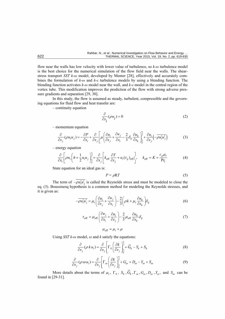
In this study, the flow is assumed as steady, turbulent, compressible and the govern-ing equations for fluid flow and heat transfer are:
– continuity equation
( ) 0uixiρ∂
=∂
(2)
– momentum equation
( )2( )3
ji k ii j ij i j
j i j j i k j
uu u uPu u u ux x x x x x x
ρ µ δ ρ⎡ ∂ ⎤⎛ ⎞∂ ∂ ∂∂ ∂ ∂ ′ ′= − + + − + −⎢ ⎥⎜ ⎟∂ ∂ ∂ ∂ ∂ ∂ ∂⎢ ⎥⎝ ⎠⎣ ⎦
(3)
– energy equation
eff eff eff1 ( ) , 2 Pr
p ti i j i ij
i j j t
cTu h u u k u k Kx x x
µρ τ
⎡ ⎤∂ ⎡ ⎤ ∂ ∂⎛ ⎞+ = + = +⎢ ⎥⎜ ⎟⎢ ⎥∂ ∂ ∂⎝ ⎠⎣ ⎦ ⎣ ⎦ (4)
State equation for an ideal gas is:
P = ρRT (5)
The term of i ju uρ ′ ′− is called the Reynolds stress and must be modeled to close the eq. (3). Boussinesq hypothesis is a common method for modeling the Reynolds stresses, and it is given as:
23
ji ki j t t ij
j i k
uu uu u k
x x xρ µ ρ µ δ
∂⎛ ⎞∂ ∂⎛ ⎞′ ′− = + − +⎜ ⎟ ⎜ ⎟∂ ∂ ∂⎝ ⎠⎝ ⎠ (6)
eff eff eff23
j i kij
i j k
u u ux x x
τ µ µ δ∂⎛ ⎞∂ ∂
= + −⎜ ⎟∂ ∂ ∂⎝ ⎠
(7)
eff tµ µ µ= +
Using SST k-ω model, ω and k satisfy the equations:
( )i k k k kj j j
kk u G Y Sx x x
ρ⎡ ⎤⎛ ⎞∂ ∂ ∂
= Γ + − +⎢ ⎥⎜ ⎟∂ ∂ ∂⎢ ⎥⎝ ⎠⎣ ⎦ (8)
( )ij j j
ku G D Y Sx x xω ω ω ω ωρω
⎡ ⎤⎛ ⎞∂ ∂ ∂= Γ + + − +⎢ ⎥⎜ ⎟∂ ∂ ∂⎢ ⎥⎝ ⎠⎣ ⎦
(9)
More details about the terms of tµ , kΓ , kS , kG , ωΓ , Gω , Dω , ,Yω and Sω can be found in [29-31].
Rahbar, N., et al.: Numerical Investigation on Flow Behavior and Energy … THERMAL SCIENCE, Year 2015, Vol. 19, No. 2, pp. 619-630 623
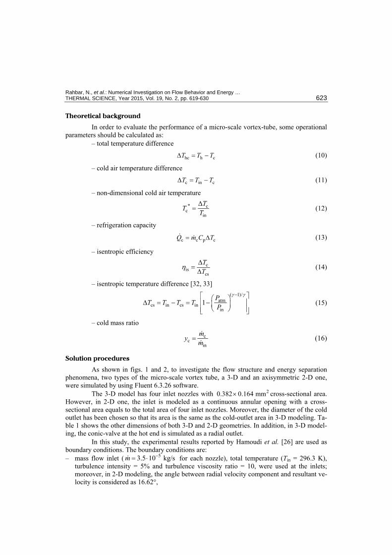
Theoretical background
In order to evaluate the performance of a micro-scale vortex-tube, some operational parameters should be calculated as:
– total temperature difference
hc h cT T T∆ = − (10)
– cold air temperature difference
c in cT T T∆ = − (11)
– non-dimensional cold air temperature
* cc
in
∆TT
T= (12)
– refrigeration capacity
c c p cQ m C T= ∆ (13)
– isentropic efficiency
cis
cs
TT
η∆
=∆
(14)
– isentropic temperature difference [32, 33]
( 1)/
atmcs in cs in
in1
PT T T T P
γ γ−⎡ ⎤⎛ ⎞∆ = − = −⎢ ⎥⎜ ⎟⎝ ⎠⎢ ⎥⎣ ⎦
(15)
– cold mass ratio
cc
in
my m= (16)
Solution procedures
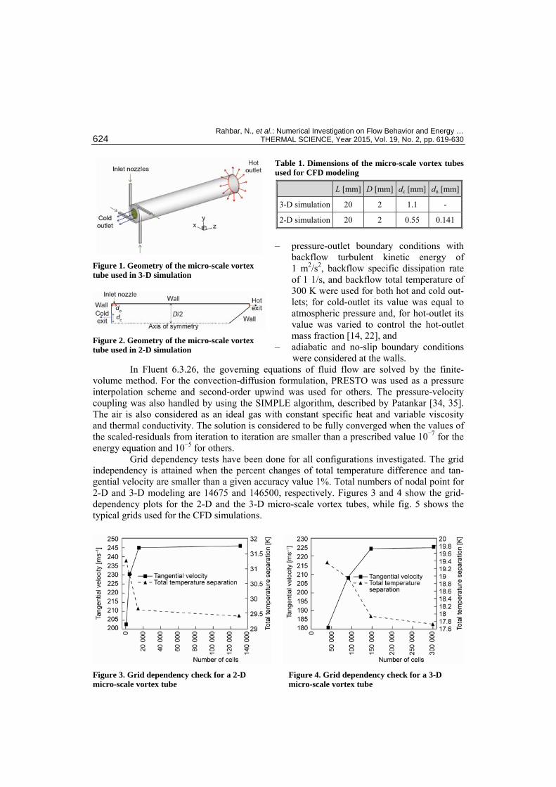
As shown in figs. 1 and 2, to investigate the flow structure and energy separation phenomena, two types of the micro-scale vortex tube, a 3-D and an axisymmetric 2-D one, were simulated by using Fluent 6.3.26 software.
The 3-D model has four inlet nozzles with 20.382 0.164 mm× cross-sectional area. However, in 2-D one, the inlet is modeled as a continuous annular opening with a cross-sectional area equals to the total area of four inlet nozzles. Moreover, the diameter of the cold outlet has been chosen so that its area is the same as the cold-outlet area in 3-D modeling. Ta-ble 1 shows the other dimensions of both 3-D and 2-D geometries. In addition, in 3-D model-ing, the conic-valve at the hot end is simulated as a radial outlet.
In this study, the experimental results reported by Hamoudi et al. [26] are used as boundary conditions. The boundary conditions are: – mass flow inlet ( 53.5 10 kg/sm −= ⋅ for each nozzle), total temperature (Tin = 296.3 K),
turbulence intensity = 5% and turbulence viscosity ratio = 10, were used at the inlets; moreover, in 2-D modeling, the angle between radial velocity component and resultant ve-locity is considered as 16.62°,
Rahbar, N., et al.: Numerical Investigation on Flow Behavior and Energy … 624 THERMAL SCIENCE, Year 2015, Vol. 19, No. 2, pp. 619-630
Table 1. Dimensions of the micro-scale vortex tubes used for CFD modeling
L [mm] D [mm] dc [mm] dn [mm]
3-D simulation 20 2 1.1 -
2-D simulation 20 2 0.55 0.141
– pressure-outlet boundary conditions with
backflow turbulent kinetic energy of 1 m2/s2, backflow specific dissipation rate of 1 1/s, and backflow total temperature of 300 K were used for both hot and cold out-lets; for cold-outlet its value was equal to atmospheric pressure and, for hot-outlet its value was varied to control the hot-outlet mass fraction [14, 22], and
– adiabatic and no-slip boundary conditions were considered at the walls.
In Fluent 6.3.26, the governing equations of fluid flow are solved by the finite-volume method. For the convection-diffusion formulation, PRESTO was used as a pressure interpolation scheme and second-order upwind was used for others. The pressure-velocity coupling was also handled by using the SIMPLE algorithm, described by Patankar [34, 35]. The air is also considered as an ideal gas with constant specific heat and variable viscosity and thermal conductivity. The solution is considered to be fully converged when the values of the scaled-residuals from iteration to iteration are smaller than a prescribed value 10−7 for the energy equation and 10−5 for others.
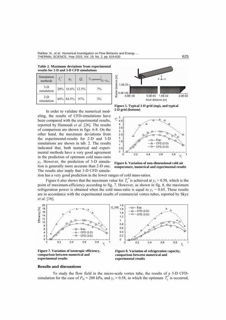
Grid dependency tests have been done for all configurations investigated. The grid independency is attained when the percent changes of total temperature difference and tan-gential velocity are smaller than a given accuracy value 1%. Total numbers of nodal point for 2-D and 3-D modeling are 14675 and 146500, respectively. Figures 3 and 4 show the grid-dependency plots for the 2-D and the 3-D micro-scale vortex tubes, while fig. 5 shows the typical grids used for the CFD simulations.
Figure 1. Geometry of the micro-scale vortex tube used in 3-D simulation
Figure 2. Geometry of the micro-scale vortex tube used in 2-D simulation
Figure 3. Grid dependency check for a 2-D micro-scale vortex tube
Figure 4. Grid dependency check for a 3-D micro-scale vortex tube
Rahbar, N., et al.: Numerical Investigation on Flow Behavior and Energy … THERMAL SCIENCE, Year 2015, Vol. 19, No. 2, pp. 619-630 625
Table 2. Maximum deviations from experimental results for 2-D and 3-D CFD simulations Simulation methods
*cT ηis Qc
c maxc,optimum Q Q
y=
3-D simulation 20% 16.6% 12.5% 7%
2-D simulation 84% 84.5% 97% 3%
In order to validate the numerical mod-
eling, the results of CFD-simulations have been compared with the experimental results, reported by Hamoudi et al. [26]. The results of comparison are shown in figs. 6-8. On the other hand, the maximum deviations from the experimental-results for 2-D and 3-D simulations are shown in tab. 2. The results indicated that, both numerical and experi-mental methods have a very good agreement in the prediction of optimum cold mass-ratio yc. However, the prediction of 3-D simula-tion is generally more accurate than 2-D one. The results also imply that 3-D CFD simula-tion has a very good prediction in the lower ranges of cold mass-ratios.
Figure 6 also shows that the maximum value for *cT is achieved at yc = 0.58, which is the
point of maximum-efficiency according to fig. 7. However, as shown in fig. 8, the maximum refrigeration power is obtained when the cold mass-ratio is equal to yc = 0.65. These results are in accordance with the experimental results of commercial vortex-tubes, reported by Skye et al. [16].
Figure 7. Variation of isentropic efficiency, comparison between numerical and experimental results
Figure 8. Variation of refrigeration capacity, comparison between numerical and experimental results
Results and discussions
To study the flow field in the micro-scale vortex tube, the results of a 3-D CFD-simulation for the case of Pin = 200 kPa, and yc = 0.58, in which the optimum *
cT is occurred,
Figure 5. Typical 3-D grid (top), and typical 2-D grid (bottom)
Figure 6. Variation of non-dimensional cold air temperature, numerical and experimental results
Rahbar, N., et al.: Numerical Investigation on Flow Behavior and Energy … 626 THERMAL SCIENCE, Year 2015, Vol. 19, No. 2, pp. 619-630
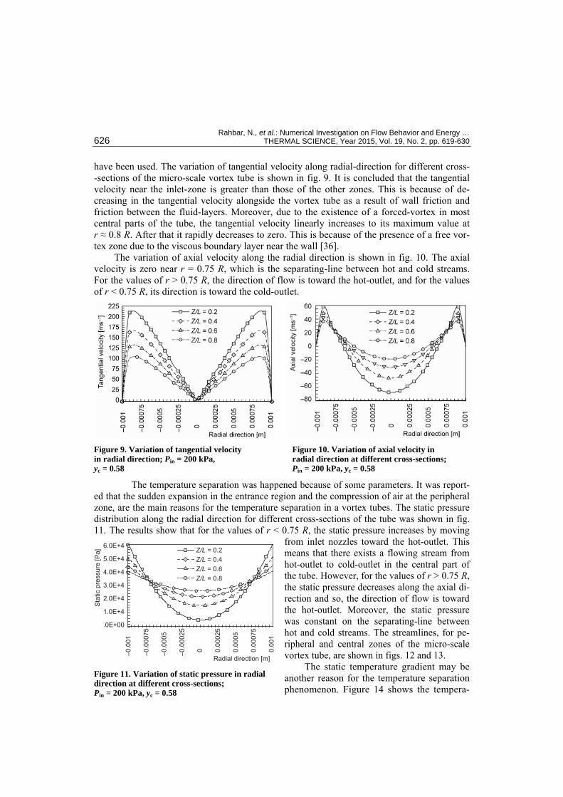
have been used. The variation of tangential velocity along radial-direction for different cross- -sections of the micro-scale vortex tube is shown in fig. 9. It is concluded that the tangential velocity near the inlet-zone is greater than those of the other zones. This is because of de-creasing in the tangential velocity alongside the vortex tube as a result of wall friction and friction between the fluid-layers. Moreover, due to the existence of a forced-vortex in most central parts of the tube, the tangential velocity linearly increases to its maximum value at r ≈ 0.8 R. After that it rapidly decreases to zero. This is because of the presence of a free vor-tex zone due to the viscous boundary layer near the wall [36].
The variation of axial velocity along the radial direction is shown in fig. 10. The axial velocity is zero near r = 0.75 R, which is the separating-line between hot and cold streams. For the values of r > 0.75 R, the direction of flow is toward the hot-outlet, and for the values of r < 0.75 R, its direction is toward the cold-outlet.
Figure 9. Variation of tangential velocity in radial direction; Pin = 200 kPa, yc = 0.58
Figure 10. Variation of axial velocity in radial direction at different cross-sections; Pin = 200 kPa, yc = 0.58
The temperature separation was happened because of some parameters. It was report-ed that the sudden expansion in the entrance region and the compression of air at the peripheral zone, are the main reasons for the temperature separation in a vortex tubes. The static pressure distribution along the radial direction for different cross-sections of the tube was shown in fig. 11. The results show that for the values of r < 0.75 R, the static pressure increases by moving
from inlet nozzles toward the hot-outlet. This means that there exists a flowing stream from hot-outlet to cold-outlet in the central part of the tube. However, for the values of r > 0.75 R, the static pressure decreases along the axial di-rection and so, the direction of flow is toward the hot-outlet. Moreover, the static pressure was constant on the separating-line between hot and cold streams. The streamlines, for pe-ripheral and central zones of the micro-scale vortex tube, are shown in figs. 12 and 13.
The static temperature gradient may be another reason for the temperature separation phenomenon. Figure 14 shows the tempera-
Figure 11. Variation of static pressure in radial direction at different cross-sections; Pin = 200 kPa, yc = 0.58
6.0E+4
5.0E+4
4.0E+4
3.0E+4
2.0E+4
1.0E+4
.0E+00
Sta
tic p
ress
ure
[Pa]
–0.0
01
–0.0
0075
–0.0
005
–0.0
0025
0 0.0
0025
0.0
005
0.0
0075
0.0
01
Radial direction [m]
Z/L = 0.2Z/L = 0.4Z/L = 0.6Z/L = 0.8
Rahbar, N., et al.: Numerical Investigation on Flow Behavior and Energy … THERMAL SCIENCE, Year 2015, Vol. 19, No. 2, pp. 619-630 627
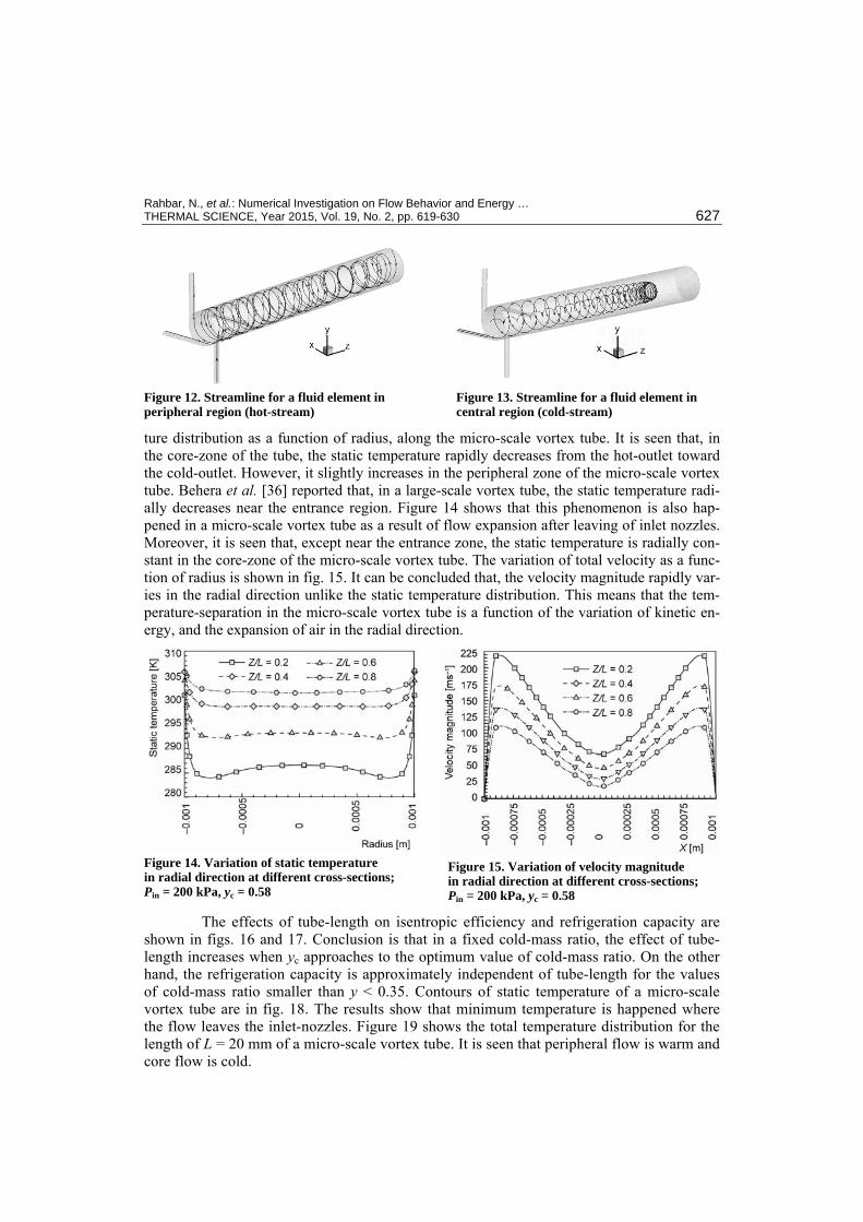
Figure 12. Streamline for a fluid element in peripheral region (hot-stream)
Figure 13. Streamline for a fluid element in central region (cold-stream)
ture distribution as a function of radius, along the micro-scale vortex tube. It is seen that, in the core-zone of the tube, the static temperature rapidly decreases from the hot-outlet toward the cold-outlet. However, it slightly increases in the peripheral zone of the micro-scale vortex tube. Behera et al. [36] reported that, in a large-scale vortex tube, the static temperature radi-ally decreases near the entrance region. Figure 14 shows that this phenomenon is also hap-pened in a micro-scale vortex tube as a result of flow expansion after leaving of inlet nozzles. Moreover, it is seen that, except near the entrance zone, the static temperature is radially con-stant in the core-zone of the micro-scale vortex tube. The variation of total velocity as a func-tion of radius is shown in fig. 15. It can be concluded that, the velocity magnitude rapidly var-ies in the radial direction unlike the static temperature distribution. This means that the tem-perature-separation in the micro-scale vortex tube is a function of the variation of kinetic en-ergy, and the expansion of air in the radial direction.
Figure 14. Variation of static temperature in radial direction at different cross-sections; Pin = 200 kPa, yc = 0.58
Figure 15. Variation of velocity magnitude in radial direction at different cross-sections; Pin = 200 kPa, yc = 0.58
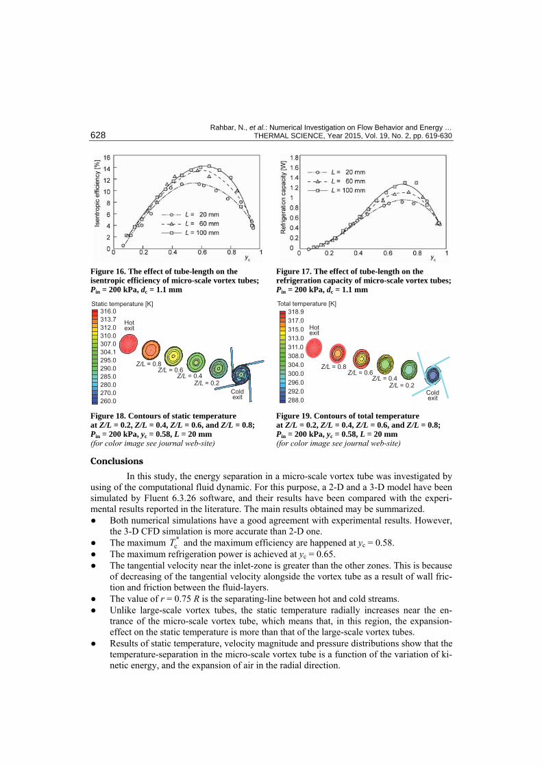
The effects of tube-length on isentropic efficiency and refrigeration capacity are shown in figs. 16 and 17. Conclusion is that in a fixed cold-mass ratio, the effect of tube-length increases when yc approaches to the optimum value of cold-mass ratio. On the other hand, the refrigeration capacity is approximately independent of tube-length for the values of cold-mass ratio smaller than y < 0.35. Contours of static temperature of a micro-scale vortex tube are in fig. 18. The results show that minimum temperature is happened where the flow leaves the inlet-nozzles. Figure 19 shows the total temperature distribution for the length of L = 20 mm of a micro-scale vortex tube. It is seen that peripheral flow is warm and core flow is cold.
Rahbar, N., et al.: Numerical Investigation on Flow Behavior and Energy … 628 THERMAL SCIENCE, Year 2015, Vol. 19, No. 2, pp. 619-630
Figure 16. The effect of tube-length on the isentropic efficiency of micro-scale vortex tubes; Pin = 200 kPa, dc = 1.1 mm
Figure 17. The effect of tube-length on the refrigeration capacity of micro-scale vortex tubes; Pin = 200 kPa, dc = 1.1 mm
Figure 18. Contours of static temperature at Z/L = 0.2, Z/L = 0.4, Z/L = 0.6, and Z/L = 0.8; Pin = 200 kPa, yc = 0.58, L = 20 mm (for color image see journal web-site)
Figure 19. Contours of total temperature at Z/L = 0.2, Z/L = 0.4, Z/L = 0.6, and Z/L = 0.8; Pin = 200 kPa, yc = 0.58, L = 20 mm (for color image see journal web-site)
Conclusions
In this study, the energy separation in a micro-scale vortex tube was investigated by using of the computational fluid dynamic. For this purpose, a 2-D and a 3-D model have been simulated by Fluent 6.3.26 software, and their results have been compared with the experi-mental results reported in the literature. The main results obtained may be summarized. ● Both numerical simulations have a good agreement with experimental results. However,
the 3-D CFD simulation is more accurate than 2-D one. ● The maximum *
cT and the maximum efficiency are happened at yc = 0.58. ● The maximum refrigeration power is achieved at yc = 0.65. ● The tangential velocity near the inlet-zone is greater than the other zones. This is because
of decreasing of the tangential velocity alongside the vortex tube as a result of wall fric-tion and friction between the fluid-layers.
● The value of r = 0.75 R is the separating-line between hot and cold streams. ● Unlike large-scale vortex tubes, the static temperature radially increases near the en-
trance of the micro-scale vortex tube, which means that, in this region, the expansion-effect on the static temperature is more than that of the large-scale vortex tubes.
● Results of static temperature, velocity magnitude and pressure distributions show that the temperature-separation in the micro-scale vortex tube is a function of the variation of ki-netic energy, and the expansion of air in the radial direction.
Static temperature [K]
Hotexit
Coldexit
316.0313.7312.0310.0307.0304.1295.0290.0285.0280.0270.0260.0
Z/L = 0.2Z/L = 0.4
Z/L = 0.6Z/L = 0.8
Hotexit
Coldexit
318.9317.0315.0313.0311.0308.0304.0300.0296.0292.0288.0
Total temperature [K]
Z/L = 0.2Z/L = 0.4
Z/L = 0.6Z/L = 0.8
Rahbar, N., et al.: Numerical Investigation on Flow Behavior and Energy … THERMAL SCIENCE, Year 2015, Vol. 19, No. 2, pp. 619-630 629
● In a fixed cold-mass ratio, the effect of tube-length increases when yc approaches to the optimum value of cold-mass ratio.
● The refrigeration capacity is approximately independent of tube-length for the values of cold-mass ratio smaller than y < 0.35.
Acknowledgment
This work was supported by the Office of the Vice Chancellor for Research, Islamic Azad University, Semnan Branch, with Grant No.1108 – 21/05/1389. The authors would like to express their grateful thanks to Islamic Azad University, Semnan Branch, for providing in-formation, experimental facilities, and their close co-operation.
Nomenclature A – area, [m2] cp – specific heat at constant pressure, [Jkg–1K–1] D, dn – diameter, [m] h – mass average enthalpy, [Jkg–1] K – thermal conductivity, [Wm–1K–1] Kn – Knudsen number, [–] k – turbulence kinetic energy, [m2s–2] L – length, [m] M – Mach number, [–] m – mass flow rate, [kgs–1] P – pressure, [Pa] Pr – Prandtl number, [–]
cQ – refrigeration capacity, [W] R – specific constant of an ideal gas, [Jkg–1K–1] Re – Reynolds number, [–] T – temperature, [K] u – mass averaged velocity, [ms–1] u' – fluctuating velocity component, [ms–1] yc – cold mass fraction, [–]
Greek symbols
γ – specific heat ratio, (cp/cv), [–] δij – Kronecker delta ηis – isentropic efficiency µ – viscosity, [Nsm–2] µt – eddy viscosity, [Nsm–2] ρ – density, [kgm–3] τ – stress tensor ω – specific dissipation rate
Subscripts
in – inlet c – cold h – hot is – isentropic hc – hot-cold atm – atmospheric
References [1] Ranque, G., Experiments on Expansion in a Vortex with Simultaneous Exhaust of Hot Air and Cold Air,
Le Journal de Physique et le Radium,4 (1933), 6, pp. 112-114 [2] Ranque, G., Method and Apparatus for Obtaining from a Fluid under Pressure Two Outputs of Fluid at
Different Temperatures, US Patent 1:952, 281, 1934 [3] Hilsch, R., The Use of the Expansion of Gases in a Centrifugal Field as Cooling Process, Review of Sci-
entific Instruments,18 (1947), 2, pp. 108-113 [4] Eiamsa-Ard, S., Promvonge, P., Numerical Simulation of Flow Field and Temperature Separation in a
Vortex Tube, International Communications in Heat and Mass Transfer, 35 (2008), 8, pp. 937-947 [5] Saidi, M. Valipour, M., Experimental Modeling of Vortex Tube Refrigerator, Applied Thermal Engi-
neering, 23 (2003), 15, pp. 1971-1980 [6] Gao, C., et al., Experimental Study on a Simple Ranque-Hilsch Vortex Tube, Cryogenics, 45 (2005), 3,
pp. 173-183 [7] Aydin, O., Baki, M., An Experimental Study on the Design Parameters of a Counterflow Vortex Tube,
Energy, 31 (2006), 14, pp. 2763-2772 [8] Hamdan, M., et al., Experimental Analysis on Vortex Tube Energy Separation Performance, Heat and
Mass Transfer, 47 (2011), 12, pp. 1637-1642 [9] Wu, Y. T., et al., Modification and Experimental Research on Vortex Tube, International Journal of Re-
frigeration, 30 (2007), 6, pp. 1042-1049 [10] Nimbalkar, S. U., Muller, M. R., An Experimental Investigation of the Optimum Geometry for the Cold
End Orifice of a Vortex Tube, Applied Thermal Engineering, 29 (2009), 2-3, pp. 509-514
Rahbar, N., et al.: Numerical Investigation on Flow Behavior and Energy … 630 THERMAL SCIENCE, Year 2015, Vol. 19, No. 2, pp. 619-630
[11] Valipour, M. S., Niazi, N., Experimental Modeling of a Curved Ranque-Hilsch Vortex Tube Refrigera-tor, International Journal of Refrigeration, 34 (2011), 4, pp. 1109-1116
[12] Frohlingsdorf, W., Unger, H., Numerical Investigations of the Compressible Flow and the Energy Separa-tion in the Ranque-Hilsch Vortex Tube, Int. Journal of Heat and Mass Transfer, 42 (1999), 3, pp. 415-422
[13] Keyes Jr, J., An Experimental Study of Gas Dynamics in High Velocity Vortex Flow, Proceedings, Heat Transfer and Fluid Mechanics Institute, Stanford University, Oak Ridge National Laboraty, Tenn., USA, 1960, pp. 31-46
[14] Behera, U., et al., CFD Analysis and Experimental Investigations towards Optimizing the Parameters of Ranque-Hilsch Vortex Tube, Int. Journal of Heat and Mass Transfer, 48 (2005), 10, pp. 1961-1973
[15] Aljuwayhel, N. F., et al., Parametric and Internal Study of the Vortex Tube Using a CFD Model, Inter-national Journal of Refrigeration, 28 (2005), 3, pp. 442-450
[16] Skye, H. M., et al., Comparison of CFD Analysis to Empirical Data in a Commercial Vortex Tube, In-ternational Journal of Refrigeration, 29 (2006), 1, pp. 71-80
[17] Eiamsa-ard, S., Promvonge, P., Numerical Investigation of the Thermal Separation in a Ranque-Hilsch Vortex Tube, International Journal of Heat and Mass Transfer, 50 (2007), 5-6, pp. 821-832
[18] Ameri, M., Behnia, B., The Study of Key Design Parameters Effects on the Vortex Tube Performance, Int. Journal of Thermal Science, 18 (2009), 4, pp. 370-376
[19] Farouk, T., Farouk, B., Large Eddy Simulations of the Flow Field and Temperature Separation in the Ranque-Hilsch Vortex Tube, Int. Journal of Heat and Mass Transfer, 50 (2007), 23-24, pp. 4724-4735
[20] Farouk, T., et al., Simulation of Gas Species and Temperature Separation in the Counter-Flow Ranque- -Hilsch Vortex Tube Using the Large Eddy Simulation Technique, Int. Journal of Heat and Mass Trans-fer, 52 (2009), 13-14, pp. 3320-3333
[21] Hossein-Nezhad, A. Shamsoddini, R., Numerical Three-Dimensional Analysis of the Mechanism of Flow and Heat Transfer in a Vortex Tube, Thermal Science, 13 (2009), 4, pp. 183-196
[22] Shamsoddini, R. Hossein-Nezhad, A., Numerical Analysis of the Effects of Nozzles Number on the Flow and Power of Cooling of a Vortex Tube, International Journal of Refrigeration, 33 (2010), 4, pp. 774-782
[23] Dutta, T., et al., Comparison of Different Turbulence Models in Predicting the Temperature Separation in a Ranque-Hilsch Vortex Tube, International Journal of Refrigeration, 33 (2010), 4, pp. 783-792
[24] Hamoudi, A. F., An Investigation of a Micro-Scale Ranque-Hilsch Vortex Tube, M. Sc. thesis, Mechanical, Automotive and Materials Engineering Department, University of Windsor, Windsor, Ont., Canada, 2006
[25] Dyskin, L., Kramarenko, P., Energy Characteristics of Vortex Microtubes, Journal of Engineering Phys-ics and Thermophysics, 47 (1984), 6, pp. 1394-1395
[26] Hamoudi, A., et al., Performance Characteristics of a Microscale Ranque-Hilsch Vortex Tube, Journal of Fluids Engineering, 130 (2008), 10, 101206
[27] Zhang, Z., Nano/Microscale Heat Transfer, McGraw-Hill Professional, 1st ed., 2007 [28] Menter, F. R., Two-Equation Eddy-Viscosity Turbulence Models for Engineering Applications, AIAA
Journal, 32 (1994), 8, pp. 1598-1605 [29] Cebeci, T., Analysis of Turbulent Flows, 2nd ed., Elsevier, San Diego, Cal., USA, 2004 [30] Cebeci, T., Turbulence Models and Their Application: Efficient Numerical Methods with Computer Pro-
grams, Horizons Pub. and Springer, New York, Berlin, 2004 [31] ***, FLUENT 6.3 User's Guide, Fluent Inc., 2006 [32] Xue, Y., et al., A Critical Review of Temperature Separation in a Vortex Tube, Experimental Thermal
and Fluid Science, 34 (2010), 8, pp. 1367-1374 [33] Yilmaz, M., et al., A Review on Design Criteria for Vortex Tubes, Waerme- und Stoffuebertragung, 45
(2009), 5, pp. 613-632 [34] Patankar, S. V., Numerical Heat Transfer and Fluid Flow, Hemisphere Pub., New York, USA, 1980 [35] Versteeg, H. K. Malalasekera, W., An Introduction to Computational Fluid Dynamics: the Finite Volume
Method, Prentice Hall, Harlow, UK, 2007 [36] Behera, U., et al., Numerical Investigations on Flow Behavior and Energy Separation in Ranque-Hilsch
Vortex Tube, International Journal of Heat and Mass Transfer, 51 (2008), 25-26, pp. 6077-6089
Paper submitted: November 26, 2014 Paper revised: January 10, 2015 Paper accepted: February 15, 2015
Related Documents


