Numerical investigation of the flameless oxidation of natural gas in the IFRF furnace using large eddy simulation Seyed Mahmood Mousavi 1 and Javad Abolfazli-Esfahani* 2 1,2 Center of Excellence on Modeling and Control Systems (CEMCS) & Mechanical Engineering Department, Ferdowsi University of Mashhad, Mashhad 91775-1111, Iran), [email protected] (Submission date: February 24, 2014; Revised Submission date: March 18, 2014; Accepted date: May 11, 2014) ABSTRACT In this paper, in order to investigate the effect of working parameters on 3D non-premixed Flameless oxidation occurring in the IFRF furnace, large eddy simulation model is applied on OpenFOAM environment. The radiation and combustion are modeled by applying the finite volume discrete ordinate model and partially stirred reactor, respectively. Furthermore the detailed mechanism GRI-2.11 is undertaken represent chemistry reactions. The obtained results are compared with the published experimental measurements. After ensuring the accuracy of the LES method, the combustion characteristics are examined with different fuel injection angles, adding H 2 O, H 2 , and the inlet Reynolds number. The results indicated significant changes in the characteristics of the Flameless oxidation process. 1. HEADING The energy production and its consumption have always been one of the human’s main concerns. Nowadays, regarding the restriction of the fossil energy resources and their environmental impacts, the researchers are trying to investigate an appropriate solution for energy saving and the reduction of pollutant emissions. In the recent years, new methodologies are presented for substantial energy savings and dramatic reduction in CO and NO x emissions. One of the approaches is the application of Flameless oxidation (FLOX) technology. FLOX technology was initially developed to minimize NO x emissions produced in industrial furnaces using high temperature preheated air [1]. In FLOX technology, the input temperature of reactants is higher, while the temperature rise during combustion is lower than the self-ignition temperature of the reactant mixture [2]. This new technology is also named “Moderate or Intense Low- oxygen Dilution (MILD)” and “high temperature air combustion (HiTAC)”. International journal of spray and combustion dynamics · Volume · 6 · Number · 4 – pages 387 – 410 387 *Corresponding author email: [email protected]

Welcome message from author
This document is posted to help you gain knowledge. Please leave a comment to let me know what you think about it! Share it to your friends and learn new things together.
Transcript

Numerical investigation of the flamelessoxidation of natural gas in the IFRFfurnace using large eddy simulation
Seyed Mahmood Mousavi1 and Javad Abolfazli-Esfahani*2
1,2Center of Excellence on Modeling and Control Systems (CEMCS) & Mechanical Engineering Department, Ferdowsi
University of Mashhad, Mashhad 91775-1111, Iran),
(Submission date: February 24, 2014; Revised Submission date: March 18, 2014; Accepted date: May 11, 2014)
ABSTRACTIn this paper, in order to investigate the effect of working parameters on 3D non-premixedFlameless oxidation occurring in the IFRF furnace, large eddy simulation model is applied onOpenFOAM environment. The radiation and combustion are modeled by applying the finitevolume discrete ordinate model and partially stirred reactor, respectively. Furthermore thedetailed mechanism GRI-2.11 is undertaken represent chemistry reactions. The obtained resultsare compared with the published experimental measurements. After ensuring the accuracy of theLES method, the combustion characteristics are examined with different fuel injection angles,adding H2O, H2, and the inlet Reynolds number. The results indicated significant changes in thecharacteristics of the Flameless oxidation process.
1. HEADINGThe energy production and its consumption have always been one of the human’s mainconcerns. Nowadays, regarding the restriction of the fossil energy resources and theirenvironmental impacts, the researchers are trying to investigate an appropriate solutionfor energy saving and the reduction of pollutant emissions. In the recent years, newmethodologies are presented for substantial energy savings and dramatic reduction inCO and NOx emissions. One of the approaches is the application of Flamelessoxidation (FLOX) technology. FLOX technology was initially developed to minimizeNOx emissions produced in industrial furnaces using high temperature preheated air [1].In FLOX technology, the input temperature of reactants is higher, while thetemperature rise during combustion is lower than the self-ignition temperature of thereactant mixture [2]. This new technology is also named “Moderate or Intense Low-oxygen Dilution (MILD)” and “high temperature air combustion (HiTAC)”.
International journal of spray and combustion dynamics · Volume · 6 · Number · 4 – pages 387 – 410 387
*Corresponding author email: [email protected]

In the last two decades, this type of combustion has examined experimentally andnumerically. Weber et al. [3] investigated experimentally the MILD combustion ofdifferent fuels, i.e., natural gas (NG), light fuel oil (LFO), heavy fuel oil (HFO), andcoal. In their investigation, the oxidizer included 20% oxygen, 60% nitrogen, 14%water vapor, and 6% carbon dioxide at 1300 oC. They found that the MILDcombustion process of light oil was similar to that of natural gas to a great deal whilethe MILD combustions of heavy fuel oil and coal were significantly different alwayswith visible flames. Lille et al. [4] experimentally studied HiTAC combustion of asingle fuel jet of Gasol (> 95% of propane). Their studies revealed that the combustionof Gasol in hot and oxygen depleted flue gases appeared to be so stable and complete.They also found that reduced oxygen concentration in the flue gases increased theflame size and lift-off distance but decreased luminosity and visibility. Their resultsdisplayed that the HiTAC flame becomes first bluish then appeared to be non-visibleat the oxygen concentration below 15% in the oxidizer. Their measurement of reactantconcentrations inside the combustion chamber confirmed that the HiTAC flamevolume and surface were much larger than conventional combustion. Very lowemissions of exhaust NOx and CO were measured in their experiment. Colorado et al.[5] investigated experimentally performance of FLOX using biogas and natural gas.They found that, in both cases, NOx and CO emissions were very low, lower than 3ppm and 16 ppm, respectively. When the system was fueled by biogas, the efficiencywas 2% lower than in the case of natural gas combustion, and a minor reduction of thetemperature field was found. A study by Danon et al. [6] on low calorific value fuelsused in MILD combustion shows that low NOx emissions were achieved. Thecharacteristics of a multi-burner Flameless oxidation furnace were investigatedexperimentally [7-8] and numerically [9] in the semi-industrial 300kW regenerativeFLOX system available in the Process & Energy Laboratory of TU Delft. Burnerconfigurations (their positioning) and operating modes (parallel and staggered firing)were compared in the combustion tests performed, studying their effect on furnaceefficiency, emissions (NO, CO) and temperature uniformity. The results showed thatthe parallel mode has lower emissions of NOx and CO due to the temperatureuniformity [10]. Also, it was observed that the NOx emissions in stagger mode aresystematically higher than in parallel mode for all positions. These results were foundunder the same operating condition (i.e. Preheated combustion air, combustion air andfuel flow rates). Furthermore, comparisons between horizontal configuration andtriangular configuration, horizontal configuration showed lower NOx emission thanthe triangular configuration [11].
There are a great number of relevant numerical studies available in the literature.Christo and Dally [12] tested several models for MILD combustion and found thatthe eddy dissipation concept (EDC) model with a detailed kinetic scheme was thebest. Recently, HiTAC was also simulated for coal [13-15]. Mardani and Tabejamaat[16] studied the effect of H2 on H2-CH4 turbulent non-premixed flame under MILDcombustion regime by using CFD. They found that the reduction of hydrogen in fuellead to enlarge the reaction zone volume, and to reduce the mixture fraction andstrain rate. Moreover, the radial spreading of flame decreased by addition of
388 Numerical investigation of the flameless oxidation of natural gas in the IFRF furnace usinglarge eddy simulation

hydrogen to the fuel mixture. Mardani et al. [17] studied numerically the importanceof molecular diffusion versus turbulent transport in the MILD combustion mode.Their results demonstrated that the molecular diffusion in MILD combustion couldnot be ignored in comparison with the turbulent transport. They also observed thatthe inclusion method of molecular diffusion in combustion modeling had aconsiderable effect on the accuracy of numerical modeling of MILD combustion.Their results showed that by decreasing the jet Reynolds number and the oxygenconcentration in the airflow or increasing H2 in the fuel mixture, the influence ofmolecular diffusion on MILD combustion increased. Mi et al. [18] investigated theinfluence of the injection momentum rate of premixed air and fuel on the MILDcombustion in a recuperative combustion chamber by using the computational fluiddynamic (CFD). They found that the flue gas recirculation played an essential rolein establishing the premixed MILD combustion. They also found that there was acritical momentum rate of the fuel-air mixture, under which the MILD combustiondid not happen. Moreover, the momentum rate of the fuel-air mixture had a lesssignificant influence on conventional global combustion than on MILD combustion.Parente et al. [19] presented a simplified modeling approach for the prediction ofNOx formation in MILD combustion at low temperatures with high concentration ofH2 in the fuel stream for a semi-industrial combustion chamber. They comparedCFD predictions with the experimental data. Their examination indicated that theproposed CFD model had the capability to provide a satisfactory description of thesystem over the wide range of operating conditions. Also, they found that reasonablepredictions of NOx formation were achieved only when an accurate characterizationof the temperature field taking into account of all the relevant NOx formation routesof the investigated operating conditions. For instance, the inclusion of non-conventional NOx formation routes, N2O and NNH, were crucial for characterizingthe pollutant emissions from the combustion at low temperatures and with hydrogenadded fuel. Vascellari et al. [15] investigated the MILD combustion of pulverizedcoal numerically, using a new heterogeneous combustion sub-model. Coelho andPeters [20], Ihme and Chee [21], and Afarin and Tabejamaat [22] confirmed the largeeddy simulation (LES) for modeling the FLOX combustion.
Due to immense applications of this technology in the various industries, andwith regard to previous studies, this technology requires further investigations tounderstand the behavior of different modes of combustion. In the present study,FLOX technology is simulated using OpenFOAM environment. In this context, LESmethod and partially stirred reactor (PaSR) are applied in order to model turbulenceand combustion, respectively. The flow field is discretized using the control volumemethod and PISO algorithm coupled the pressure and velocity fields. The results arecompared with the available experimental data [23]. The good agreement betweenthe present numerical and published experimental data [23] validates the usedmethod and confirms its ability to model the similar cases. After verifying the resultsof simulation, the effects of using injection with an angle into the combustionchamber, effect of adding H2O, H2, and also the inlet Reynolds number on severalworking parameters are examined.
International journal of spray and combustion dynamics · Volume . 6 · Number . 4 . 2014 389

2. MATHEMATICAL MODELThe governing equations including the Favre-averaged form of continuity, momentum,energy, species conservation, and LES equations are solved in order to simulate theflow field numerically [24]. The so-called Top-hat filter [25] is applied for dividing thequantities into filtered and unfiltered quantities. The Favre-averaged and Smagorinskymodel [25] are used for averaging of the filtered quantities in Navier-Stokes equationsand modeling the unfiltered quantities, respectively. In this study, C++ libraryOpenFOAM is used for numerical simulation. Here the flow solver is based on thePISO algorithm [26]. The DRM-22 which is a reduced version of the GRI1.2, modelsthe chemical kinetics [26]; it consists of 22 species and 104 reversible reactions. Thetime step is about 10-6 s, which is reduced to 10-8 s when the combustion starts.
2.1. Large eddy simulationThe naturally three dimensional and unsteady turbulent flows are often influenced bystrong non-homogeneous effects and rapid transformations which prevent using theisotropic models in simulations. The modified sub-grids methods which can improveLES methodologies are also presented, although their usage is confined due to theirnatural complexity. Therefore new methods for simulating the sub-grids scale are inprogress. In common methods some models are presented to consider the effects of sub-grids scale in filtered Navier-Stokes equations [27]. LES is more common than theother models. In this model at first large scales should be solved with energy which isgiven to them. For this purpose the effect of the small scales which are waste, shouldbe considered in energy balance. In LES methodology, the filter is used to separate thelarge scales from small ones [28]. Therefore all variables like f are divided into twoparts, grid and sub-grid. In other words, where is sub-gridtension. In variable density flow where [28].
By filtering the variables in the compressible Navier-Stokes equations, theinstantaneous filtered equation leads to the following equations. A more detaileddiscussion can be found in the textbooks by Poinsot and Veynante [29].
(1)
(2)
(3)
(4)
In the above equations, the symbols ˜ and ¯ indicate filtered Faver and filteredquantities, respectively, and u is the velocity vector, p is the pressure, r is the flow
= + ′f f f ρ ρ=f f
�ρ
ρ( )∂
∂+
∂
∂=
t xu. 0
ii
ρρ μ
μω( )∂
∂+
∂
∂=
∂
∂+
⎛
⎝⎜⎜
⎞
⎠⎟⎟∂
∂
⎛
⎝⎜⎜
⎞
⎠⎟⎟ +
Y
t xu Y
x Sc
Y
xk=1,...,Nk
i
i k
i
SGS
t
k
i
ρρ τ μ
δ( )∂
∂+
∂
∂+∂
∂=
∂
∂+
∂
∂+∂
∂
⎛
⎝⎜⎜
⎞
⎠⎟⎟ +
⎛
⎝
⎜⎜
⎞
⎠
⎟⎟
u
t xu u
p
x x
u
x
u
xT
3i
i
i j
i i
ij SGSi
j
i
i
ijkk
ρρ
μ μ( )∂
∂+
∂
∂=
∂
∂+
⎛
⎝⎜⎜
⎞
⎠⎟⎟∂
∂
⎛
⎝⎜⎜
⎞
⎠⎟⎟
h
t xu h
Dp
Dt x
h
xPr Pri
i
i
SGS
t i
ρ ρ=f f= + ′′f f f
390 Numerical investigation of the flameless oxidation of natural gas in the IFRF furnace usinglarge eddy simulation

density, h is the enthalpy, Yk is the mass fraction of kth species, and d is the Kroneckerdelta. The isentropic contribution, Tkk, in equation (which is twice the sub-grid scaleturbulent kinetic energy) is unknown and usually absorbed into the filtered pressure.Furthermore, Sct and Prt are considered as unity. All terms in the above equations areclosed except the species transport’s (Eq. (2)) source term. Furthermore the sub-gridscale kinetic energy obtained by,
(5)
The μSGS is the sub-grid scale viscosity; eSGS is the sub-grid scale dissipation, t is thestress tensor which are computed according to the expressions,
(6)
(7)
(8)
where, Ck and Ce are set to 0.2 and 1.048 in this study. In addition the grid scale rate ofstress tensor ( ) is defined as follows:
(9)
The DRM-22, a reduced version of the GRI1.2, models the chemical kinetics; itconsists of 22 species and 104 reversible reactions. Finally, reaction mechanism isexpressed in equation (10),
(10)
In the above relation, kfj and kbj are constant rates of equilibrium reaction.Furthermore, the filtered species reaction rates are,
(11)
In which the jth reaction rate is:
(12)
where, according to Equation (3), Yi is the mass fraction of specie i.
μρ
τ ε∂
∂+∂
∂=
∂
∂
∂
∂
⎛
⎝⎜⎜
⎞
⎠⎟⎟ −
∂
∂−
K
t
u K
x x
K
x
u
xPrSGS j SGS
i i
SGS
t
SGS
i
ijj
i
SGS
μ ρ= ΔC KSGS k SGS
ε =Δ
C K KSGS
e SGS SGS
τμρ
δ= − +S K22
3ijSGS
ij SGS ij
Sij
=
∂
∂+∂
∂
⎛
⎝⎜⎜
⎞
⎠⎟⎟S
u
x
u
x
1
2iji
j
j
i
∑ ∑′ℑ ⎯ →⎯⎯⎯⎯← ⎯⎯⎯⎯⎯ ′′ℑ
= =P Piji
N
i
k
kiji
N
i1 1
f j
b j
,
,
ω ω( )= ′′− ′M P Pi i ij ij j
∏ ∏ω ρ ρ( ) ( )= −=
′
=
′′
k Y k Yj f i ii
N P
b j ii
N P
, 1 , 1
ij ij
International journal of spray and combustion dynamics · Volume . 6 · Number . 4 . 2014 391

2.2. PaSR methodThe turbulent flow is related to the combustion terms using the PaSR method. InPaSR method each computational cell is divided into two parts, reactive andunreactive. In reactive part it is supposed that the participant components in reactionare mixed well, which is the main assumption of PSR method. The final mixtureconsists of both burned and unburned gases as the results of reactive and unreactiveparts respectively. The ratio of reactive to unreactive parts in PaSR is calculated as[26, 30]:
(13)
In the above equation is mixing time and Cmix is equal to one.The value of time step in the chemical reaction (tc) is determined based on total molarconcentration in each computational cell and average of its variations. The value of thedepreciation rate of sub-grid vortex ( ) is evaluated as:
(14)
The constant value in the above equation is considered to be the standard value ofthe model which is equal to 1.048. Based on PaSR model, the rate of molarconcentration changes of chemical components is estimated by equation (15).
(15)
In this equation, and are the values of final concentration and initialconcentration of species i, respectively. Also, residence time (tres) is equal to time stepof the solution. It should be noted that the relation between PaSR method and LESmethodology is based on reaction rate. Therefore, by using this method (R) the speciestransport equation changes to the equation below:
(16)
2.3. Entropy generationThe irreversibility in fluid flow is caused by heat transfer and viscosity. Entropygeneration in this collection, by determining the temperature and velocity profile, isconsidered as below:
(17)
R=-c
c mix
ττ τ
τ μ ρε( )= Cmix mix eff
ε
= C k kεΔ
ε
Ct= C -C = (C )
i1i
0i
resi 1
iω∂
∂ τ
Ci0Ci
1
( ) ( )′′ = ′′′ + ′′′S S Sgen gen heat gen fric
�� ��Y
t xY u
x xY R
ij
it
j
ρρ μ μ ω( ) ( )( )∂
∂+
∂
∂=
∂
∂+
∂
∂
⎛
⎝⎜⎜
⎞
⎠⎟⎟
αα
392 Numerical investigation of the flameless oxidation of natural gas in the IFRF furnace usinglarge eddy simulation

First and second terms of equation (16) are associating the heat and chemical,correspondingly:
(18)
(19)
F is presented in equation (20),
(20)
According to the Honig [31] researches, entropy generation is caused by heattransfer, friction and also it is caused by species dispersion especially reaction rate incombustion phenomena. These values can be obtained for species dispersion andreaction rate as below:
(21)
(22)
Where mM,i is molar chemical potential for species i, the (i) component coefficient inreactant side is and is the same species coefficient but in product side. Forcalculating the entropy generation rate in the whole combustion chamber and inCartesian coordinates it is presented as:
(23)
2.4. DiscretizationThe discretization scheme with higher order is needed in LES methodology, because thesub-grid terms covering using leading-order truncation error should be prevented.Totally, sub-grid terms are proportional with Dp such that 4/3<P<2. The filter width (D)is usually related to generated grids and also produces the modeled sub-grid scalestresses and flux parameters whereas their magnitude are equal to O(|d|p). It should be
λ( ) ( ) ( ) ( )′′′ = ⋅ ∂ ∂ + ∂ ∂ + ∂ ∂⎡⎣
⎤⎦S T T x T y T z( )gen heat eff
2 2 2 2
∑ωυ υ μ( ) ( )= ′ − ′′ >( )Ω
=
ST
0gen CH i i M i
i
N
,
1
Φ = ⋅∂
∂⎛⎝⎜
⎞⎠⎟+
∂
∂
⎛
⎝⎜⎞
⎠⎟+
∂
∂⎛⎝⎜
⎞⎠⎟
⎡
⎣⎢⎢
⎤
⎦⎥⎥
∂
∂+∂
∂+∂
∂
⎛
⎝⎜⎞
⎠⎟u
x
v
y
w
z
u
x
v
y
w
z2 +
2 2 2
∑ρω ω( ) =
∂
∂
∂
∂+
∂
∂
∂
∂
⎡
⎣⎢⎢
⎤
⎦⎥⎥>
α α α α
( )Ω
=
S Dp
Y
z
p
z Y
Y
z
Y
z0gen D im
i i i
i
i i
i
N
1
∑ωυ υ μ( ) ( )= ′ − ′′ >( )Ω
=
ST
0gen CH i i M i
i
N
,
1
υ′′iυ′i
∫= ′′′ ⋅ ⋅S S dx dy dzgen genV
International journal of spray and combustion dynamics · Volume . 6 · Number . 4 . 2014 393

considered that |d| is magnitude of grid in D�|d|. In LES methodology, spectral or pseudospectral, and high-order finite volume or finite difference methods are used for spatialdiscretization, and explicit semi-implicit or predictor–corrector methods of at leastsecond-order accuracy is used for time integration. On the other hand LES methodologydoes not usually filter for time domain, therefore, it should be solved for those scales inwhich (—t < tk) where —t is time step and tk is Kolmogorov time scale. Furthermore,Courant number lower than 0.2 is suitable while only large scale should be remained.
According to definition of cell average approximation f on the pth-cell, Gauss theoryis used to extract the semi discretization equations of LES methodology.
All the calculations are preceded by utilizing OpenFOAM environment and due toentropy generation computation, the numerical codes of C++ is added to OpenFOAMsolver. It should be pointed out that the computations are done with getting help fromparallel processing center of Ferdowsi University of Mashhad.
3. GEOMETRY AND BOUNDARY-CONDITIONSThe combustion chamber which, considered in the present work is shown schematicallyin Fig. 1. The oxidizer was supplied through the central channel with an injectionvelocity of 80 m s-1. The fuel was supplied through two injectors with an injectionvelocity of 110 m s-1. According to the Fig. 1, the fuel injectors were located 0.280 maway from the combustion chamber centerline. In addition, the diameters of fuel,oxidizer, and outlet nozzle are 0.0273, 0.125, and 0.75 m, respectively. Moreover, the
394 Numerical investigation of the flameless oxidation of natural gas in the IFRF furnace usinglarge eddy simulation
−1
−0.5
0
0.5
1
−1−0.5
00.5X
Y
Z
10
1
2
3
Outlet
Fuel inlet
Fuel inlet
Air inlet
R = 0.375 m
4
φ125 mm
280 mm
φ27.3 mm
56
7
Figure 1: A Schematic of the combustion chamber.

length, width, and height of the combustion chamber are 6.25, 2, and 2 m, individually.The inlet velocity, temperature, and composition of fuel/oxidizer are also illustratedobviously in table 1 in order to compare the numerical results with the availableexperimental data [23]. No slip, impenetrable and constant temperature conditions areapplied for walls. Additionally the pressure of the outlet is constant and is consideredto be 1 atm.
4. GRID INDEPENDENCY TESTIn order to obtain the optimum number of grids in terms of speed, accuracy ofsolution, and grid independency, the model has been solved with 10 different sizes ofgrids, and the results have been reported as an average temperature chart on thecentral line (Z direction), average temperature at the outlet of the combustionchamber and average speed at Z = 3.1 m. According to Fig.2, when the number of the
3000
2800
2600
2400
2200
2000
1800
1600
1400
1200
1000
0
20
25
30
35
40
45
50
55
60
65
70
75
1E+06 2E+06
Number of grid
Average temperature- center line Average temperature- outputAverage velocity- Z = 3.1 m
Ave
rage
vel
ocity
(m
/s)
3E+06 4E+06 5E+06
Ave
rage
tem
pera
ture
(K
)
Figure 2: Effect of different cell numbers.
Table 1: The input conditions of the simulation, consistent with [23]
Velocity (m.s-1) Temperature (K) Composition % (vol)
Fuel 80 300 CH4 87.8%, C2H6 4.6%, C3H8 1.6%, C4H10 0.5%, N2 5.5%
Oxidizer 110 1600 wet O2 19.5%, wet N2 60%, H2O 15%, wet CO2 6%, NO 110 ppm
International journal of spray and combustion dynamics · Volume . 6 · Number . 4 . 2014 395

computational cells is more than 3.8 ¥ 106, the results will approximately be constant.Considering this low deviation and the computational costs, grid with 3.8 ¥ 106 cellshas been used in this work.
5. RESULT AND DISCUSSION5.1. Solution validation processPope [32] and Veynante [33] stated that the simulation of LES methodology has highaccuracy while the ratio of kinetic energy to turbulence-resolution tolerance (a) is morethan 80%. Figure 3 indicates Y-direction variations of a in four sections 0.4, 1.4, 3, and5.5 m from the inlet nozzles. It is observed that the amount of a reaches more than 89%in all parts of the surface. Thus, LES methodology’s accuracy for current modelstimulation is confirmed.
In order to comparison of PDF model results [23] with results of the present study,Fig. 4 displays temperature profile and NOx emission in Y-direction where z axis isequal to 0.73 m. As it is evident, to compare with experimental data the accuracy of thenumerical results of present study is much greater than PDF model [23]. The errorswhich are appeared in PDF method in most points are caused by inability of this modelto predict the local extinction probably. The result shows the ability of LESmethodology to the prediction of the FLOX behavior.
Figures 5 show the distribution of velocity along the Y-direction at Z equal to 0.735and 2.05 m, respectively. This figure compares numerical solution from the LESturbulence methodology to experimental data [23]. To evaluate the accuracy of the
396 Numerical investigation of the flameless oxidation of natural gas in the IFRF furnace usinglarge eddy simulation
Z = 0.4 mZ = 1.4 mZ = 3 mZ = 5.5 m
0.93
0.925
0.92
0.915
0.91
0.905
0.9
0.895
0.89
0.885−1 −0.8 −0.6 −0.4 −0.2
Y direction (m)
α
0 0.2 0.4 0.6 0.8 1
Figure 3: Variations of a versus Y-direction in four sections 0.4, 1.4, 3, and 5.5 mfrom the inlet of the nozzles.

0501000
Temperature (K)
Y -
dire
ctio
n (m
)
NOx emission (ppm)
0
0.1
0.2
0.3
0.4
0.5
0.6
Mancini experimentPDF Method result of ManciniPresent work
0.7
1500 2000 100 150 200
0.1
0.2
0.3
0.4
0.5
0.6
0.7
Figure 4: Temperature and NOx profile in Y-direction.
Experimental dataPresent work
Velocity (m.s−1) Velocity (m.s−1)
Y -
dire
ctio
n (m
)
0 000
0.2
0.4
0.6
0.8
1
0.2
0.4
0.6
0.8
1
20 40 6020 40 60
Figure 5: Velocity profiles in Y- Direction.
International journal of spray and combustion dynamics · Volume . 6 · Number . 4 . 2014 397

numerical results, the following formula is used to calculate the correlation coefficientstatistical parameter, i.e., R [34]. Higher value for this parameter indicates moreaccurate numerical solution.
(23)
As is shown in Figs. 5, the result obtained from the LES turbulence model isconsistent with an accuracy of about 95.5% with the experimental data. The high valueof R for the LES methodology confirms suitable accuracy of this model for simulationof the FLOX technology.
Since the mixing in the LES is absolutely essential for validation the results of LESmethodology, Figs. 6 display the comparison between the result of numerical methodand experimental data for CH4 distribution. It is clear that the obtained results of LEScoincided with high accuracy with experimental data, as the root of R square for bothof them figures is about 0.96.
RZ Z Z Z
Z Z
exp,i simulation,meani
n
exp,i simulation,ii
n
exp,i simulation,meani
n
2
1
2
12
1
∑ ∑∑
( ) ( )( )
=− − −
−= =
=
398 Numerical investigation of the flameless oxidation of natural gas in the IFRF furnace usinglarge eddy simulation
00
0
2
4
6
8
10
0.1 0.2 0.3 0.4 0.5 0.6 0.7
0.1
b-Z = 2.05 m
a-Z = 0.15 m
Mancini experimentPresent work
Y - direction (m)
CH
4 (%
dry
)C
H4
(% d
ry)
0.2 0.3 0.4 0.5 0.6 0.7
10
20
30
40
50
60
Figure 6: Distribution of CH4.

After ensuring the accuracy of the simulation method, the combustion behavior isexamined by using fuel injection with an angle in the combustion chamber, adding H2O, H2,and also the variation of inlet Reynolds number on several parameters.
5.2. Effects of change the fuel injection angleFigure 7(a-b) shows the flow path while without chemical reaction for different casesof injection, including direct injection and injection with an angle. The combustionchamber is divided into zones 1 and 2 based on the location of the fuel and the oxidizercollision region. As it is seen in Fig. 7(a-b), using direct injection leads to collision ofthe inlet streams in zone 2, while the fuel injection with angle leads to the flowcollision in zone 1. Thus, there are more opportunities and time for the mixing of fueland oxidizer. Additionally, it is clear that, whatever the injection angle increases, thelocation of mixing flows (fuel and oxidizer) moves closer to the inlet region, and theinlet jets collide more rapidly, which increases the turbulence intensity.
Figure 8a shows the variation of the average sub-grid kinetic energy for various fuelinjection angles in the axial direction (along the z axis). As it is evident, applying injectionwith an angle, the amounts of maximum and local sub-grid kinetic energy in thecombustion chamber are increased. As turbulence intensity is the main factor of bettermixing, consequently using this kind of injection provides perfect combustion andeffectively decreases pollutant, which results in higher efficiency. On the other hand,according to the Fig. 8b, the average reaction rate is increased by using injection with anangle. Attention to Eq. (15), the rate of molar concentration changes of chemicalcomponents is dependent on the net rate of reaction, then, applying injection with an angleinto the combustion chamber is increased the rate of molar concentration changes ofchemical components. Therefore, the results of Figs. 8(a-b) prove the more completecombustion.
Figure 9(a-d) shows the variation of maximum flame temperature with varying fuelinjection angle. In all cases of Fig. 9, the maximum flame temperatures increase withincreasing the fuel injection angle. Cavaliere and Joannon [2] have expressed thatFLOX technology is, generally, relevant if the inlet temperature and the temperaturerise (Tmax - Toxi) are, respectively, slightly higher and lower than the auto-ignition one.
ZZ
Zone 1Zone 2
Zone 1 Zone 2
Y Y
XX
(a) Direct injection (b) Injection with an angle
Figure 7: The flow paths of air and fuel in the combustion chamber.
International journal of spray and combustion dynamics · Volume . 6 · Number . 4 . 2014 399

400 Numerical investigation of the flameless oxidation of natural gas in the IFRF furnace usinglarge eddy simulation
1
0
−10
10
20
30
40
50
60
(a) (b)
2 3 4 5 1
0
0.03
0.06
0.09
0.12
0.15
2 3
Z- direction (m)
Rea
ctio
n ra
te (
kgm
ol.m
−3
.s−
1 )
Sub
-grid
kin
etic
ene
rgy
(m2
.s−
2 )
Z- direction (m)
Injection angle = 0° Injection angle = 5° Injection angle = 10° Injection angle = 15°
4 5
Injection angle = 0° Injection angle = 5° Injection angle = 10° Injection angle = 15°
Figure 8: Distribution of (a)– average sub-grid kinetic energy and (b)– a averagereaction rate through the z-direction for different injection angles.
6
5
4
3
2
1
0
(a) Injection angle = 0°
1600 K
6
5
4
3
2
1
0
(b) Injection angle = 5°
6
5
4
3
2
1
0
(c) Injection angle = 10°
6
5
4
3
2
1
0
(d) Injection angle = 15°
2270 K 2480 K 2730 K
Figure 9: Distribution of mean temperature (K) (horizontal axis = x-coordinate,vertical axis = z-coordinate)
Flameless oxidation mode may satisfy with the condition of (Tmax - Toxi.) < Tfl < Toxi.,where Tmax is maximum flame temperature, Toxi oxidizers temperature, and Tflflammable temperature. Meanwhile, the condition (Tmax - Toxi.) > Tfl is satisfied withhigh-temperature combustion mode. Anyway, Fig. 9 shows that the maximumcombustion temperatures increase by growing the fuel injection angle. With respect tothe above description, increase the angle up to 10°, there is a Flameless combustion. Butat an angle of 15°, due to the increase in combustion temperature, Flameless combustionconditions are eliminated and there is a high temperature combustion process.Furthermore, the position of the maximum temperatures moved toward to the inletnozzles, by raising the angle of injection.

The effect of the applying fuel injection with an angle on radiation to burner’swall is clearly seen in Fig. 10. As it is clear, using the fuel injection with an angleinto the combustion chamber increases the amount of radiation to the walls of thecombustion chamber. As already discussed above, the amount of temperature isincreased, and thus increasing the amount of radiation to the combustion chamber’swall is expected to be over.
Fig. 11 (a-d) indicates the average entropy distribution in the combustion chamber fordifferent kinds of fuel injection. In this figure, it can be clearly seen that, applying fuelinjection with an angle increases the entropy generation. Increase the entropy generationdue to the increase in the reaction rate according to Eqs. (20) and (21) is predictable.Additionally, in section (2.3) it is shown that, the entropy generation increases byapplying injection with an angle into the combustion chamber for two reasons: increasein the reaction rate and pressure gradients, which are the source of entropy generation.
5.3. Effects of adding H2O (Vapor)Dilution is a method in which by adding a dilutor (which has a high thermalcapacity), the thermal capacity of the mixture increases and this leads to lowertemperature inside the furnace and less pollutant emissions [35]. This section showsthe effect of using the H2O vapor (0, 7.5, and 15% Vol.) to the combustion. H2Ovapor raises the thermal capacity of the mixture and thermal absorption, thereforeleads to lower flame temperature and NOx production [36]. Figure 12(a-c) shows theaverage temperature profiles for three different cases. As the vapor enters the
Injection angle = 0° Injection angle = 5° Injection angle = 10° Injection angle = 15°
820
800
780
760
740
720
700
680
660
640
6200.5 1 1.5 2 2.5 3
Z- direction (m)
Rad
iatio
n he
at tr
ansf
er (
kW.m
−2 )
3.5 4 4.5 5 5.5 6
Figure 10: Distribution of average radiation heat transfer to the wall.
International journal of spray and combustion dynamics · Volume . 6 · Number . 4 . 2014 401

combustion chamber, the maximum temperature decreases. In fact, the vapor actslike a thermal sink and absorbs the combustion chamber heat. For vapor percent of0, 7.5, and 15, the maximum temperatures are about 1670, 1575, and 1530 K,respectively. Nevertheless it should be noted that the vapor injection does not leadto a remarkable change in the flow pattern.
Figure 13(a-c) shows the average NOx profiles according to ppm. As it is expected,the maximum value of NOx has been formed at the point with the maximumtemperature. In fact, the basic duty of vapor injection is to reduce flame temperaturepick. In this case the vapor reduces the flame temperature, by reaching this effect to theheart of combustion flow field, without making any change to flow pattern. By
402 Numerical investigation of the flameless oxidation of natural gas in the IFRF furnace usinglarge eddy simulation
Figure 11: Distribution of entropy generation average (kJ.K-1.S-1) (horizontal axis =x-coordinate, vertical axis = z-coordinate).
6
5
4
3
2
1
0(a) Injection angle = 0°
1600 2000 2400
(b) Injection angle = 5° (c) Injection angle = 10° (d) Injection angle = 15°
1600 2100 2600 1600 2200 2800 1528.66 2535.54 3542.43
0.6
0.45
0.3
Y-di
rect
ion
(m)
0.15
01000 1500
Temperature (K)
(a) Z = 0.15 (m)
2000
0.6
0.45
7.5%-H20
0.3
Y-di
rect
ion
(m)
0.15
01000 1500
Temperature (K)
(b) Z = 0.7 (m)
2000
0.6
0.45
0.3
Y-di
rect
ion
(m)
0.15
01000 1200 1400 1600
Temperature (K)
(c) Z = 1 (m)
1800
15%-H20
0.0%-H20
Figure 12: Average temperature profiles along Y- Direction.
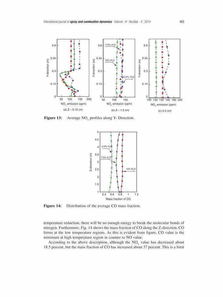
temperature reduction, there will be no enough energy to break the molecular bonds ofnitrogen. Furthermore, Fig. 14 shows the mass fraction of CO along the Z-direction. COforms at the low temperature regions. As this is evident from figure, CO value is theminimum at high temperature region in counter to NO value.
According to the above description, although the NOx value has decreased about18.5 percent, but the mass fraction of CO has increased about 37 percent. This is a limit
0.6
0.45
0.3
Y-di
rect
ion
(m)
0.15
050 100 150
NOX emission (ppm) NOX emission (ppm) NOX emission (ppm)
(a) Z = 0.15 (m)
200
0.6
0.45
7.5%-H20
0.3
Y-di
rect
ion
(m)
0.15
050 100 150
(b) Z = 1.5 (m)
0.6
0.45
0.3
Y-di
rect
ion
(m)
0.15
0100 120 140 160
(c) 2.5 (m)
180 200
15%-H20
0.0%- H20
Figure 13: Average NOx profiles along Y- Direction.
Z-d
irect
ion
(m)
Mass fraction of CO
1
7.5% H2O
15% H2O
1.5
2
2.5
3
3.5
4
4.5
5
0.4 0.6 0.8 1 1.2
0.0% H2O
Figure 14: Distribution of the average CO mass fraction.
International journal of spray and combustion dynamics · Volume . 6 · Number . 4 . 2014 403

for vapor injection. Dilution combustions may lead to some defects, such as extinction,low combustion efficiency, and high compactness of CO. A practical solution toovercome these defects is to inject reactive fuels such as hydrogen [37-39]
5.4. Effects of adding H2In this section the effect of fuel hydrogen content on temperature distribution,entropy generation, not consumed CH4, mass fraction of CO, and NO formation inFLOX technology is studied by increase in the hydrogen content of fuel mixturefrom 0% (by vol.) to 20% for condition of Table 2. According to Figs. 15 (a-d), itcan be seen that the maximum of temperature increases for higher hydrogenconcentrations. Followed by, based on the second law of thermodynamics, theentropy generation increases by raising the value of H2 (see Fig. 16a). It ispredictable as a result of higher reactivity of hydrogen in comparison with CH4.Moreover, Figure 16b shows the changing of CH4 mass fraction on theStoichiometric line at several distances from inlet nozzles. It should be noted that,the amount of CH4 is not the amount of fuel consumed. Due to the flammability ofhydrogen compared to CH4 is higher, the amount of not consumed fuel decreasedby increasing the value of H2. Fig. 16c shows a decrease in the mass fraction ofCO by intensification of fuel hydrogen content, because the temperature hasincreased. Furthermore, the NOx formation increases with increasing the H2concentration, which means the NO formation routes, are suppressed at lower H2levels (see Fig. 16d).
5.5. Effect of inlet Reynolds NumberIn this section, changing the combustion characteristics is studied by increasing the inletReynolds number up to 15%. Results of several Reynolds numbers are compared with
404 Numerical investigation of the flameless oxidation of natural gas in the IFRF furnace usinglarge eddy simulation
Table 2: Input conditions of the simulation for section 4.4
Inlet Velocity (m.s-1) Temperature (K) Composition %(vol)
Fuel-case 1 80 300 CH4 87.8%, C2H6 4.6%, C3H8 1.6%, C4H10
0.5%, N2 5.5%
Fuel-case 2 80 300 CH4 82.8%, C2H6 4.6%, C3H8 1.6%, C4H10
0.5%, H2 5%, N2 5.5%
Fuel-case 3 80 300 CH4 77.8%, C2H6 4.6%, C3H8 1.6%, C4H10
0.5%, H2 10%, N2 5.5%
Fuel-case 4 80 300 CH4 67.8%, C2H6 4.6%, C3H8 1.6%, C4H10
0.5%, H2 20%, N2 5.5%
Oxidizer 110 1600 wet O2 19.5%, wet N2 60%, H2O 15%, wet
CO2 6%, NO 110 ppm

Figure 15: Contour of the average temperature.
1600 K
1773 K1990 K
2180 K
6
5
4
3
2
1
0(a) 0.0% H2 (b) 5% H2 (c) 10% H2 (d) 20% H2
0.0 H2
0.05 H2
0.1 H2
0.2 H2
0.0 H2
0.05 H2
0.1 H2
0.0 H2
0.05 H2
0.1 H2
0.2 H2
0.0 H2
0.05 H2
0.1 H2
0.2 H2
4500
0.04 1800
1500
1200
900
600
300
0
0.035
0.03
0.025
0.02
0.015
0.01
0.005
0
3000
1500
0
1 2 3 4 5 6
Ent
ropy
gen
erat
ion
(kJ)
Mas
s fr
actio
n of
CO
0.48
0.4
0.32
0.24
0.16
0.08
0
CH
4 C
(%vo
l)
Z-coordinate (m)
0 1 2 3 4 5 6
Z-coordinate (m)
0 1 2 3 4 5 6
Z-coordinate (m)
(c) Average mass fraction of CO (d) Average NOX emission
0 0.5 1 1.5
Z-coordinate (m)
(a) Average entropy generation (b) Average CH4 distribution
NO
em
issi
on (
ppm
)
0.2 H2
0.2 0.4 0.6
0.2
0.25
0.3
0.35
0.4
0.45
Figure 16: Profiles of several parameters when adding H2 to the combustion process.
International journal of spray and combustion dynamics · Volume . 6 · Number . 4 . 2014 405

406 Numerical investigation of the flameless oxidation of natural gas in the IFRF furnace usinglarge eddy simulation
Figure 17: Z- Axial average temperature distribution.
3000
2500
2000
Tem
pera
ture
(K
)
1500
1000
0.4 0.8 1.2 1.6 2 2.4 2.8z-direction (m)
3.2 3.6
15% reduction7.5% reductionNo change (0%)7.5% increment15% increment
4 4.4 4.8 5.2500
each other in Figs 17. Figure 17 shows an in reduction maximum of axial temperatureprofile at higher Reynolds number. Furthermore the NO mass fraction is decreased byincrement of inlet Reynolds number. The numerical results of Mardani et al. [17] andalso the experimental results of Medwell et al. [40] show that there is a marginalincrease in temperature by the decrease of jet Reynolds number, although theconcentration of intermediate species like CH2O has decreased. Maybe it is because ofhigher heat transfer from reaction zone and also incomplete combustion due to increaseof flow velocity. Although an increase in temperature and also the flow residence timeat lower Reynolds number could be an acceptable reason of higher NOx formation forthe present experimental setup.
6. CONCLUSIONThis study has performed a numerical investigation of the characteristics of FLOXtechnology in the IFRF Furnace using Large Eddy Simulation model and OpenFOAMenvironment. The effect of different fuel injection angle and operating parameters on thevitiation and establishment of FLOX technology has been presented. These parametersinclude the mass fraction of fuel diluents (H2O), adding H2, and also the inlet Reynoldsnumber. These data have been used to investigate the resulting first collision distance, theimpact on maximum average temperature, sub-grid kinetic energy, net reaction rate,entropy generation, mass fraction of CO, and NO emission of the FLOX technology. Toverify the suitability of the CFD model and initial and boundary conditions, acomparison was made to average velocity and temperature distributions for selectedreference cases measured by Mancini et al. [23]. The model was found to agree

reasonably well with published experimental data. The modeling study has demonstratedthat varying each of the inlet parameters can considerably influence the characteristicsof the FLOX technology. The important obtained results are following:
• As more as the fuel injection angle increases, the fuel and oxidizer flows meet ina shorter length and the flows collide together with more strength. This leads to asignificant increase in sub-grid kinetic energy, reaction rate and radiation heattransfer to the walls. Besides, by increasing the fuel injection angle the maximumcombustion temperature rises significantly until that for the injection angles morethan 15 degrees, the combustion paradigm is high temperature combustion ratherthan Flameless combustion. Moreover, the entropy generation increases becauseof the reaction rate increase in the combustion process.
• Vapor injection leads to a reduction in temperature pick and NOx emission. But, theCO emission increases and this exerts a limitation for using water as an oxidizer.
• While using Hydrogen as a fuel in the combustion process, the temperature,entropy generation and NOx generation increases and the CO and unburned CH4decrease due to the high flammability of the hydrogen.
• By increasing the inlet Reynolds number, the maximum combustion temperatureand NOx emission decreases, and the CO emission increases. This occurs becausethe flow velocity and heat transfer from the reaction zone increases.
REFERENCES[1] J.A. Wünning and J.G. Wünning, Flameless oxidation to reduce thermal no-
formation, Progress in Energy and Combustion Science, 1997, 23, 81–94.
[2] A. Cavaliere and M. de Joannon, MILD Combustion, Progress in Energy andCombustion Science, 2004, 30, 329–366.
[3] R. Weber, J.P. Smart and W.v. Kamp, On the (MILD) combustion of gaseous,liquid, and solid fuels in high temperature preheated air, Proceedings of theCombustion Institute, 2005, 30, 2623–2629.
[4] S. Lille, W. Blasiak and M. Jewartowski, Experimental study of the fuel jetcombustion in high temperature and low oxygen content exhaust gases, Energy,2005, 30, 373–384.
[5] A.F. Colorado, B.A. Herrera and A.A. Amell, Performance of a Flamelesscombustion furnace using biogas and natural gas, Bioresource Technology, 2010,101, 2443–2449.
[6] B. Danon, W. de Jong, and D.J.E.M. Roekaerts, Experimental and NumericalInvestigation of a FLOX Combustor Firing Low Calorific Value Gases,Combustion Science and Technology, 2010, 182, 1261–1278.
[7] B. Danon, E.S. Cho, W. de Jong and D.J.E.M. Roekaerts, Parametric optimizationstudy of a multi-burner Flameless combustion furnace, Applied ThermalEngineering, 2011, 31, 3000–3008.
[8] E.S. Cho, B. Danon, W. de Jong and D.J.E.M. Roekaerts, Behavior of a 300kWregenerative multi-burner Flameless oxidation furnace, Applied Energy, 2011, 88,4952–4959.
International journal of spray and combustion dynamics · Volume . 6 · Number . 4 . 2014 407

[9] B. Danon, E.-S. Cho, W. de Jong and D.J.E.M. Roekaerts, Numericalinvestigation of burner configuration effects in a multi-burner Flamelesscombustion furnace, Applied Thermal Engineering, 2011, 31, 3885–3896
[10] B. Danon, E.-S. Cho, W. de Jong, W. Yang and D.J.E.M. Roekaerts, Emission andEfficiency Comparison of Different Firing Modes in a Furnace with Four HiTACBurners, Combustion Science and Technology, 2011, 183, 686–703.
[11] E.-S. Cho, D. Shin, J. Lu, W. de Jong and D.J.E.M. Roekaerts, Configurationeffects of natural gas fired multi-pair regenerative Flameless oxidation furnace onefficiency and emission, Applied Energy, 2013, 107, 25–32.
[12] F.C. Christo and B.B. Dally, Modeling turbulent reacting jets issuing into a hotand diluted coflow, Combustion and Flame, 2005, 142, 117–129.
[13] J.P. Kim, U. Schnell, G. Scheffknecht and A.C. Benim, Numerical modelling ofMILD combustion for coal, Progress in Computational Fluid Dynamics, 2007, 7,337–346.
[14] N. Schaffel, M. Mancini, A. Szle¸k and R. Weber, Mathematical modeling ofMILD combustion of pulverized coal, Combustion and Flame, 2009, 156,1771–1784.
[15] M. Vascellari, S. Schulze, P. Nikrityuk, D. Safronov and C. Hasse, NumericalSimulation of Pulverized Coal MILD Combustion Using a New HeterogeneousCombustion Submodel, Flow, Turbulence and Combustion, 2014, 92, 319–45.
[16] A. Mardani and S. Tabejamaat, Effect of hydrogen on hydrogen–methaneturbulent non-premixed flame under MILD condition, International Journal ofHydrogen Energy, 2010, 35, 11324–11331.
[17] A. Mardani, S. Tabejamaat and M. Ghamari, Numerical study of influence ofmolecular diffusion in the Mild combustion regime, Combustion Theory andModeling, 2010, 14, 747–774.
[18] J. Mi, P. Li and C. Zheng, Numerical Simulation of Flameless PremixedCombustion with an Annular Nozzle in a Recuperative Furnace, Chinese Journalof Chemical Engineering, 2010, 18, 10–17.
[19] A. Parente, C. Galletti and L. Tognotti, A simplified approach for predicting NOformation in MILD combustion of CH4–H2 mixtures, Proceedings of theCombustion Institute, 2011, 33, 3343–3350.
[20] P.J. Coelho and N. Peters, Unsteady modelling of a piloted methane/air jet flamebased on the Eulerian particle flamelet model, Combustion and Flame, 2001, 124,444–465.
[21] M. Ihme and Y.C. See, LES Flamelet modeling of a three-stream MILDcombustor: Analysis of flame sensitivity to scalar inflow conditions, Proceedingsof the Combustion Institute, 2011, 33, 1309–1317.
[22] Y. Afarin and S. Tabejamaat, The effect of fuel inlet turbulence intensity onH2/CH4 flame structure of MILD combustion using the LES method, CombustionTheory and Modeling, 2012, 17, 383–410.
408 Numerical investigation of the flameless oxidation of natural gas in the IFRF furnace usinglarge eddy simulation

[23] M. Mancini, R. Weber and U. Bollettini, Predicting NOx emissions of a burneroperated in Flameless oxidation mode, Proceedings of the Combustion Institute,2002, 29, 1155–1163.
[24] C. Fureby and G. Tabor, Mathematical and Physical Constraints on Large-EddySimulations, Theoret Comput Fluid Dynamics, 1997, 9, 85–102.
[25] C. Fureby and F.F. Grinstein, Large Eddy Simulation of High-Reynolds-NumberFree and Wall-Bounded Flows, Journal of Computational Physics, 2002, 181,68–97.
[26] W. Hua, L. Yong-chang, W. Ming-rui and Z. Yu-sheng, Multidimensionalmodeling of Dimethyl Ether (DME) spray combustion in DI diesel engine, J.Zheijang Univ.-Sci. A, 2005, 6, 276–282.
[27] S. Huang and Q.S. Li, A new dynamic one-equation sub-grid-scale model forlarge eddy simulations, International Journal for Numerical Methods inEngineering, 2010, 81, 835–865.
[28] M. Chapuis, C. Fureby, F. Fedina, N. Alin and J. Tegnér, LES modeling ofcombustion applications using OpenFOAM. Paper presented at the V EuropeanConference on Computational Fluid Dynamics (ECCOMAS CFD 2010), Lisbon,Portugal, 2010.
[29] T. Poinsot, and D. Veynante, Theoretical and Numerical Combustion, SecondEdition (second ed.), R T Edwards, 2005.
[30] A. De, E. Oldenhof, P. Sathiah and D. Roekaerts, Numerical Simulation of Delft-Jet-in-Hot-Coflow (DJHC) Flames Using the Eddy Dissipation Concept Modelfor Turbulence–Chemistry Interaction. Flow, Turbulence and Combustion, 2011,87, 537–567.
[31] J. Honig, On the Entropy of a Class of Irreversible Processes, Entropy, 2013, 15,2975–2988.
[32] S.B. Pope, Ten questions concerning the large-eddy simulation of turbulent flows.New Journal of Physics, 2004, 6, 35.
[33] D. Veynante, Large Eddy Simulations of Turbulent Combustion, Turbulence andInteractions, 2009, 105, 113–138.
[35] J. Cohen, Applied multiple regression/correlation analysis for the behavioralsciences, Lawrence Erlbaum Associates, Mahwah, N.J.; London, 2003.
[34] H. K. Kim, Y. Kim, S. M. Lee and K. Y. Ahn, NO Reduction in 0.03-0.2 MW Oxy-Fuel Combustor using Flue Gas Recirculation Technology, Proceedings of theCombustion Institute, 2007, 31, 3377–3387.
[35] E.S. Cho and S. H. Chung, Characteristics of NOx Emission with Flue GasDilution in Air and Fuel Sides, KSME International Journal, 2004, 12,2303–2309.
[36] I. Yamaoka and H. Tsuji, Anomalous Behavior of Methane-Air and Methane-Hydrogen-Air Flames Diluted with Nitrogen in a Stagnation Flow, symposium(International) on Combustion, 1992, 24, 145–152.
International journal of spray and combustion dynamics · Volume . 6 · Number . 4 . 2014 409

[37] I. Wierzba and B.B. Ale, Rich Flammability Limits of Fuel Mixtures InvolvingHydrogen at Elevated Temperatures, International Journal of Hydrogen Energy,2000, 25, 75–80.
[38] G.S. Jackson, R. Sai, J.M. Plaia and C.M. Boggs, K.T. Kiger, Influence of H2 onResponse of Lean Premixed CH4 Flames to High Strained Flows, Combustion andFlame, 2003, 132, 503–511.
[39] P.R. Medwell, P.A.M. Kalt and B.B. Dally, Simultaneous imaging of OH,formaldehyde, and temperature of turbulent non-premixed jet flames in a heatedand diluted coflow, Combust. Flame, 2007, 148, 48–61.
410 Numerical investigation of the flameless oxidation of natural gas in the IFRF furnace usinglarge eddy simulation
Related Documents