http://ibe.sagepub.com/ Indoor and Built Environment http://ibe.sagepub.com/content/early/2014/09/11/1420326X14551069 The online version of this article can be found at: DOI: 10.1177/1420326X14551069 published online 11 September 2014 Indoor and Built Environment Xiangdong Li, Kiao Inthavong and Jiyuan Tu airflows Numerical investigation of micron particle inhalation by standing thermal manikins in horizontal Published by: http://www.sagepublications.com On behalf of: International Society of the Built Environment can be found at: Indoor and Built Environment Additional services and information for http://ibe.sagepub.com/cgi/alerts Email Alerts: http://ibe.sagepub.com/subscriptions Subscriptions: http://www.sagepub.com/journalsReprints.nav Reprints: http://www.sagepub.com/journalsPermissions.nav Permissions: http://ibe.sagepub.com/content/early/2014/09/11/1420326X14551069.refs.html Citations: What is This? - Sep 11, 2014 OnlineFirst Version of Record >> at RMIT UNIVERSITY on December 2, 2014 ibe.sagepub.com Downloaded from at RMIT UNIVERSITY on December 2, 2014 ibe.sagepub.com Downloaded from

Welcome message from author
This document is posted to help you gain knowledge. Please leave a comment to let me know what you think about it! Share it to your friends and learn new things together.
Transcript

http://ibe.sagepub.com/Indoor and Built Environment
http://ibe.sagepub.com/content/early/2014/09/11/1420326X14551069The online version of this article can be found at:
DOI: 10.1177/1420326X14551069
published online 11 September 2014Indoor and Built EnvironmentXiangdong Li, Kiao Inthavong and Jiyuan Tu
airflowsNumerical investigation of micron particle inhalation by standing thermal manikins in horizontal
Published by:
http://www.sagepublications.com
On behalf of:
International Society of the Built Environment
can be found at:Indoor and Built EnvironmentAdditional services and information for
http://ibe.sagepub.com/cgi/alertsEmail Alerts:
http://ibe.sagepub.com/subscriptionsSubscriptions:
http://www.sagepub.com/journalsReprints.navReprints:
http://www.sagepub.com/journalsPermissions.navPermissions:
http://ibe.sagepub.com/content/early/2014/09/11/1420326X14551069.refs.htmlCitations:
What is This?
- Sep 11, 2014OnlineFirst Version of Record >>
at RMIT UNIVERSITY on December 2, 2014ibe.sagepub.comDownloaded from at RMIT UNIVERSITY on December 2, 2014ibe.sagepub.comDownloaded from
XML Template (2014) [8.9.2014–12:49pm] [1–14]//blrnas3/cenpro/ApplicationFiles/Journals/SAGE/3B2/IBEJ/Vol00000/140078/APPFile/SG-IBEJ140078.3d (IBE) [INVALID Stage]
IIndoorndoor andand BuiltuiltEnvironmentOriginal Paper
Numerical investigationof micron particle inhalationby standing thermal manikinsin horizontal airflows
Xiangdong Li1, Kiao Inthavong1 and Jiyuan Tu1,2
AbstractComputational fluid dynamics computations were conducted to investigate the particle inhalation char-acteristics of a thermal manikin standing in a horizontal airflow with different orientations, leg postures,wind speeds and particle sizes. The computations revealed that only when the manikin’s thermal plumemoves into the breathing zone (namely, the manikin is facing the lee side) could the body heat affect thecharacteristics of particle inhalation. Further computations demonstrated that, when facing the lee side,the manikin’s particle inhalation is highly sensitive to its leg posture. When the legs are separated, aircan flow through the gap, causing more particle entrainment into the breathing zone from the lowerlevel. Although the thermal effect of body heat is gradually suppressed with increasing wind speed orparticle size, different leg postures have different environmental sensitivities.
KeywordsThermal plume, Particle inhalation, Orientation, Leg posture, Particle size, Wind speed
Accepted: 15 August 2014
Introduction
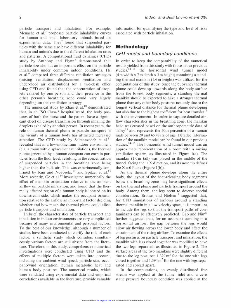
Indoor airborne particles are well known to causeadverse health effects and play an important role ininhalation exposure to particles as people nowadaysspend most of their time indoors (average 88% insidebuildings and 7% in vehicles).1 Aerosols can be anysolid particles or liquid droplets suspended in the air.Inhalation of aerosols can cause a number of healthproblems such as asthma, acute respiratory infections,chronic obstructive pulmonary disease, lung cancer andtuberculosis.2 The global outbreak of SARS in 2003and H1N1 flu in 2009 further proved that airborneparticles have great potential in transmitting infectiousdiseases.3
The process of airborne particle emission, transportand inhalation is extremely complicated and subject tothe influence of many factors. There are many sourcesfor indoor airborne particles including space heaters,printers, human activities (such as sneezing and cough-ing), as well as outdoor pollutant sources.4 Airborneparticles from different origins have different sizes,compositions, physical properties, transportabilities
and toxicological characteristics.5 Some investigations6
demonstrated that a properly designed ventilationsystem can largely improve the air quality in the breath-ing zone and hence effectively reduce the health riskassociated with particle inhalation. Therefore, substan-tial knowledge regarding the transport characteristicsof airborne particles and their inhalability by the occu-pants is of great importance for accurate health riskassessment and improved ventilation design.
During the past years, many important conclusionshave been drawn from the numerical and experimentalinvestigations aimed to identify factors influencing
1School of Aerospace, Mechanical and ManufacturingEngineering, RMIT University, Bundoora, Australia2Institute of Nuclear and New Energy Technology, TsinghuaUniversity, Beijing, China
Corresponding author:Jiyuan Tu, School of Aerospace, Mechanical andManufacturing Engineering, RMIT University, PO Box 71,Bundoora Vic 3083, Australia.Email: [email protected]
Indoor and Built Environment
0(0) 1–14
! The Author(s) 2014
Reprints and permissions:
sagepub.co.uk/
journalsPermissions.nav
DOI: 10.1177/1420326X14551069
ibe.sagepub.com
at RMIT UNIVERSITY on December 2, 2014ibe.sagepub.comDownloaded from
XML Template (2014) [8.9.2014–12:49pm] [1–14]//blrnas3/cenpro/ApplicationFiles/Journals/SAGE/3B2/IBEJ/Vol00000/140078/APPFile/SG-IBEJ140078.3d (IBE) [INVALID Stage]
particle transport and inhalation. For example,Menache et al.7 proposed particle inhalability curvesfor human and small laboratory animals based onexperimental data. They7 found that suspended par-ticles with the same size have different inhalability forhuman and animals due to the different inhalation ratesand patterns. A computational fluid dynamics (CFD)study by Anthony and Flynn8 demonstrated thatparticle size also has an important effect on the particleinhalability under common indoor conditions. Heet al.9 compared three different ventilation strategies(mixing ventilation, displacement ventilation andunder-floor air distribution) for a two-desk officeusing CFD and found that the concentration of drop-lets exhaled by one person and their presence in theother person’s breathing zone could vary largelydepending on the ventilation strategy.
The numerical study by Zhao et al.10 demonstratedthat, in an ISO Class-5 hospital ward, the body pos-tures of both the nurse and the patient have a signifi-cant effect on disease transmission through inhaling thedroplets exhaled by another person. In recent years, therole of human thermal plume in particle transport inthe vicinity of a human body has attracted increasedattention. The CFD study by Salmanzadeh et al.11
revealed that in a low-momentum indoor environment(e.g. a room with displacement ventilation), the thermalplume generated by a human occupant can entrain par-ticles from the floor level, resulting in the concentrationof suspended particles in the breathing zone beinghigher than the bulk air. This was experimentally con-firmed by Rim and Novoselac12 and Spitzer et al.13
More recently, Ge et al.14 investigated numerically theeffect of manikin orientation relative to the ambientairflow on particle inhalation, and found that the ther-mally affected region of a human body is located on itsdownstream side, which makes the occupant orienta-tion relative to the airflow an important factor decidingwhether and how much the thermal plume could affectparticle transport and inhalation.
In brief, the characteristics of particle transport andinhalation in indoor environments are very complicatedbecause of many environmental and personal factors.To the best of our knowledge, although a number ofstudies have been conducted to clarify the role of eachfactor, a synthetic study which considers simultan-eously various factors are still absent from the litera-ture. Therefore, in this study, comprehensive numericalinvestigations were conducted using CFD and theeffects of multiple factors were taken into account,including the ambient wind speed, particle size, occu-pant-wind orientation, human metabolic heat andhuman body postures. The numerical results, whichwere validated using experimental data and empiricalcorrelations available in the literature, provide valuable
information for quantifying the type and level of risksassociated with particle inhalation.
Methodology
CFD model and boundary conditions
In order to keep the comparability of the numericalresults yielded from this study with those in our previousstudies,14–16 the horizontal wind tunnel model(4mwidth�7m depth�3m height) containing a stand-ing thermal manikin (1.6m height) was utilized for thecomputations of this study. Since the buoyancy thermalplume could develop upwards along the body surfacefrom the lowest body segments, a standing thermalmanikin should be expected to have a stronger thermalplume than any other body postures not only due to thelongest vertical distance for thermal plume developingbut also due to the highest coefficient for heat transfer17
with the environment. In order to capture detailed air-flow characteristics in the breathing zone, the manikinhead was created based on the anthropometric data ofTilley18 and represents the 50th percentile of a humanmale between 20 and 65 years of age. Detailed informa-tion of the manikin model can be found in our previousstudies.14–16 The horizontal wind tunnel model was anapproximate representation of a room with a mixingventilation system, as illustrated in Figure 1(a). Themanikin (1.6m tall) was placed in the middle of thetunnel, facing the +X direction, and its nose tip definesthe X¼ 0 Plane (Figure 1(b)).
As the thermal plume develops along the entirebody, the layout of the heat-releasing body segmentsbelow the breathing zone may have significant effectson the thermal plume and particle transport around thebody. Among them, the legs seem to deserve specialconsideration. Brohus and Nielsen19 suggested that,for CFD simulations of airflows around a standingthermal manikin in a low velocity space, it is importantto include the legs so that the transport paths of con-taminants can be effectively predicted. Gao and Niu20
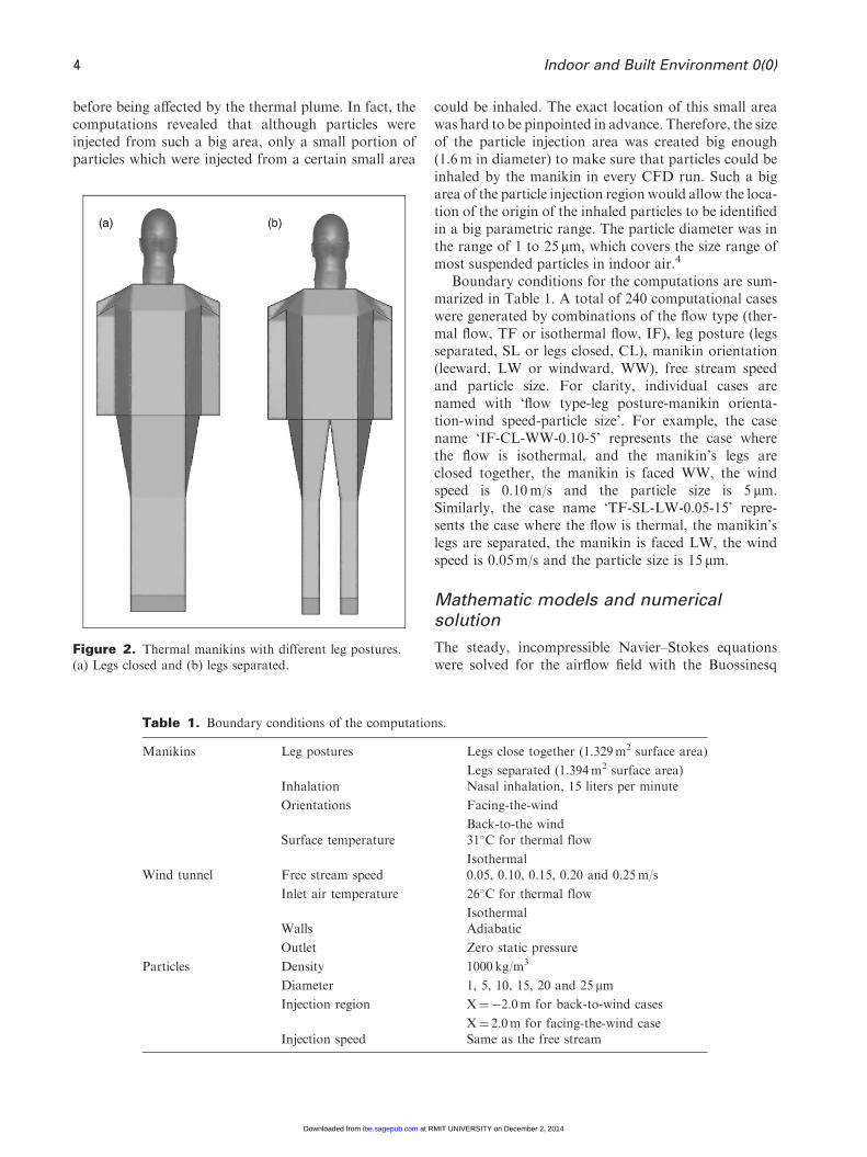
further suggested that, for an occupant standing in ahorizontal airflow, the gap between the legs wouldallow air flowing across the lower body and affect theentrainment of the rising airflow. To examine the effectsof leg postures on particle transport and inhalation, themanikin with legs closed together was modified to havethe two legs separated, as illustrated in Figure 2. Thesurface areas of the two manikins were slightly differentdue to the leg postures: 1.329m2 for the one with legsclosed together and 1.394m2 for the one with legs sepa-rated and spread apart.
In the computations, an evenly distributed freestream was applied at the tunnel inlet and a zerostatic pressure boundary condition was applied at the
2 Indoor and Built Environment 0(0)
at RMIT UNIVERSITY on December 2, 2014ibe.sagepub.comDownloaded from

XML Template (2014) [8.9.2014–12:49pm] [1–14]//blrnas3/cenpro/ApplicationFiles/Journals/SAGE/3B2/IBEJ/Vol00000/140078/APPFile/SG-IBEJ140078.3d (IBE) [INVALID Stage]
outlet. The temperature of the inlet air was assumed tobe 26�C, which is typical for an air-conditioned room inthe summer season. Different free stream speeds (0.05,0.10, 0.15, 0.20 and 0.25m/s) were applied. The freestream speed range was carefully chosen according toBaldwin and Maynard’s survey21 that the average windspeed in most modern indoor environments is in therange of 0.05 to 0.25m/s. In order to investigate theeffects of the manikin’s orientation relative to the freestream, the horizontal airflows were applied in both the+X and �X directions, which represent leeward (LW)and windward (WW) cases, respectively. Only the LWand WW cases were studied because they represent the‘worst case scenario’ for particle inhalation.22 Forinhalation simulations, the periodic respiration wasignored and a constant inhalation rate of 0.9m3/h(15 litre per minute), representing light activity condi-tions,16 was evenly applied at the manikin nostrils,namely 0.45m3/h (7.5 litre per minute) for each nostril.In fact, Rim and Novoselac12 measured the air velocityin the thermal plume above a breathing thermal
manikin and found that ‘the average velocity abovethe manikin head was around 0.20m/s with breathingand 0.21m/s without breathing. This implies that thebreathing jet does not significantly affect the buoyancythermal plume’. Therefore, it is safe to neglect the peri-odic respiration activities when simulating inhalationcharacteristics, as was also proven by Horschler et al.23
Heat transfer between the manikin and the free airstream was considered by applying a constant tempera-ture of 31�C at the manikin surface. This temperature isconsistent with the manikin surface temperature range(31�C–33.7�C)20 in most CFD studies of thermal com-fort. For the purpose of comparison, computationswere also conducted using isothermal conditions.
Particles with density of 1000 kg/m3 were injectedwith the same speed of the free stream from a circularregion, located 2.0m upstream of the nose tip, namelyX¼�2m plane, for the LW cases. For the WW cases,this location was at X¼ 2m. The particle injectionregion was located far enough from the nose tip planeso that the particle trajectories could be fully developed
(a)
(b)
Figure 1. Simplification of mixed ventilation to a horizontal flow. (a) Approximate representation of mixing ventilation
using a horizontal airflow and (b) computational domain and boundary setups.
Li et al. 3
at RMIT UNIVERSITY on December 2, 2014ibe.sagepub.comDownloaded from
XML Template (2014) [8.9.2014–12:49pm] [1–14]//blrnas3/cenpro/ApplicationFiles/Journals/SAGE/3B2/IBEJ/Vol00000/140078/APPFile/SG-IBEJ140078.3d (IBE) [INVALID Stage]
before being affected by the thermal plume. In fact, thecomputations revealed that although particles wereinjected from such a big area, only a small portion ofparticles which were injected from a certain small area
could be inhaled. The exact location of this small areawas hard to be pinpointed in advance. Therefore, the sizeof the particle injection area was created big enough(1.6m in diameter) to make sure that particles could beinhaled by the manikin in every CFD run. Such a bigarea of the particle injection region would allow the loca-tion of the origin of the inhaled particles to be identifiedin a big parametric range. The particle diameter was inthe range of 1 to 25 mm, which covers the size range ofmost suspended particles in indoor air.4
Boundary conditions for the computations are sum-marized in Table 1. A total of 240 computational caseswere generated by combinations of the flow type (ther-mal flow, TF or isothermal flow, IF), leg posture (legsseparated, SL or legs closed, CL), manikin orientation(leeward, LW or windward, WW), free stream speedand particle size. For clarity, individual cases arenamed with ‘flow type-leg posture-manikin orienta-tion-wind speed-particle size’. For example, the casename ‘IF-CL-WW-0.10-5’ represents the case wherethe flow is isothermal, and the manikin’s legs areclosed together, the manikin is faced WW, the windspeed is 0.10m/s and the particle size is 5 mm.Similarly, the case name ‘TF-SL-LW-0.05-15’ repre-sents the case where the flow is thermal, the manikin’slegs are separated, the manikin is faced LW, the windspeed is 0.05m/s and the particle size is 15 mm.
Mathematic models and numericalsolution
The steady, incompressible Navier–Stokes equationswere solved for the airflow field with the Buossinesq
Figure 2. Thermal manikins with different leg postures.(a) Legs closed and (b) legs separated.
Table 1. Boundary conditions of the computations.
Manikins Leg postures Legs close together (1.329m2 surface area)
Legs separated (1.394m2 surface area)Inhalation Nasal inhalation, 15 liters per minute
Orientations Facing-the-wind
Back-to-the windSurface temperature 31�C for thermal flow
IsothermalWind tunnel Free stream speed 0.05, 0.10, 0.15, 0.20 and 0.25m/s
Inlet air temperature 26�C for thermal flow
IsothermalWalls Adiabatic
Outlet Zero static pressure
Particles Density 1000 kg/m3
Diameter 1, 5, 10, 15, 20 and 25 mm
Injection region X¼�2.0m for back-to-wind cases
X¼ 2.0m for facing-the-wind caseInjection speed Same as the free stream
4 Indoor and Built Environment 0(0)
at RMIT UNIVERSITY on December 2, 2014ibe.sagepub.comDownloaded from

XML Template (2014) [8.9.2014–12:49pm] [1–14]//blrnas3/cenpro/ApplicationFiles/Journals/SAGE/3B2/IBEJ/Vol00000/140078/APPFile/SG-IBEJ140078.3d (IBE) [INVALID Stage]
approximation,14 which was included for the thermalbuoyancy.
The particles were tracked through the air separatelyusing the Lagrangian approach. There could be manyforces that would act on a particle submerged in a con-tinuous fluid. However, for micron particles with highdensity, the forces that depend on the density ratiowould be negligibly small.24 Therefore, only the dragforce and the buoyancy force were considered in thisstudy and the equation of particle motion is given byequation (1)
mpd U
*
p
dt¼ F
*
D þ F*
B ð1Þ
The drag force F*
D and buoyancy force F*
B aredefined by equations (2) and (3), respectively
F*
D ¼1
2CD�Ap U
*
� U*
p
��� ��� U*
� U*
p
� �ð2Þ
F*
B ¼ mp �m� �
g*¼�
6d3p �p � �� �
g*
ð3Þ
where mp,U*
p and dp are the particle mass, velocity anddiameter, respectively, Ap is the projected particle areain the flow direction. The drag coefficient CD is calcu-lated by equation (4)
CD ¼ max24
Re1þ 0:15Re0:687p
� �, 0:44
� �ð4Þ
The computational domain was discretized usingunstructured tetrahedral and prism cells. In order tocapture the effects of manikin geometry on the thermalplume, 20 layers of fine inflation cells were createdaround the manikin surface. The grid sensitivity testproved that mesh independence was achieved withapproximately 4.0 million cells for the both manikinorientation models. Another sensitivity test provedthat, when the particle track number was over 50,000,
(a)
(b) (c)
Figure 3. Velocity profiles in the breathing zone. (a) Illustration of line location, (b) facing-the-wind velocity profiles takenat the vertical line, (c) velocity profiles for different free stream velocities taken at the line for back-to-the-wind and thermal
flow case.
Li et al. 5
at RMIT UNIVERSITY on December 2, 2014ibe.sagepub.comDownloaded from
XML Template (2014) [8.9.2014–12:49pm] [1–14]//blrnas3/cenpro/ApplicationFiles/Journals/SAGE/3B2/IBEJ/Vol00000/140078/APPFile/SG-IBEJ140078.3d (IBE) [INVALID Stage]
the numerical results were independent of the particletrack number.
The Re-Normalisation Group k-" model was chosenfor the airflow turbulence because of its successful util-ization in the simulations of indoor pollutant trans-port.20 The convective terms of the transportequations were discretized using the second-order-upwind scheme in order to obtain sufficiently accuratesolutions while the pressure–velocity coupling wasresolved using the SIMPLEC algorithm. The aboveequations were solved in ANSYS CFX 13 (Ansys,Inc.) using a segregated solver with an implicit formu-lation. The residual values of the transport equationswere set to converge at 10�5 or less for all computationcases.
Results and discussion
Airflow field
The predicted airflow fields in the vicinity of the mani-kin for the WW cases have been validated usingAnthony and Flynn’s25 experimental data. For theLW cases, the airflow fields were validated with Heistet al.’s26 experimental data for the combined-leg casesand Hyun and Kleinstreuer’s27 numerical results for theseparated-leg cases. The comparisons demonstratedthat the predicted overall airflow fields agreed wellwith the published data. Details of the validationmethod have been highlighted elsewhere.14–16
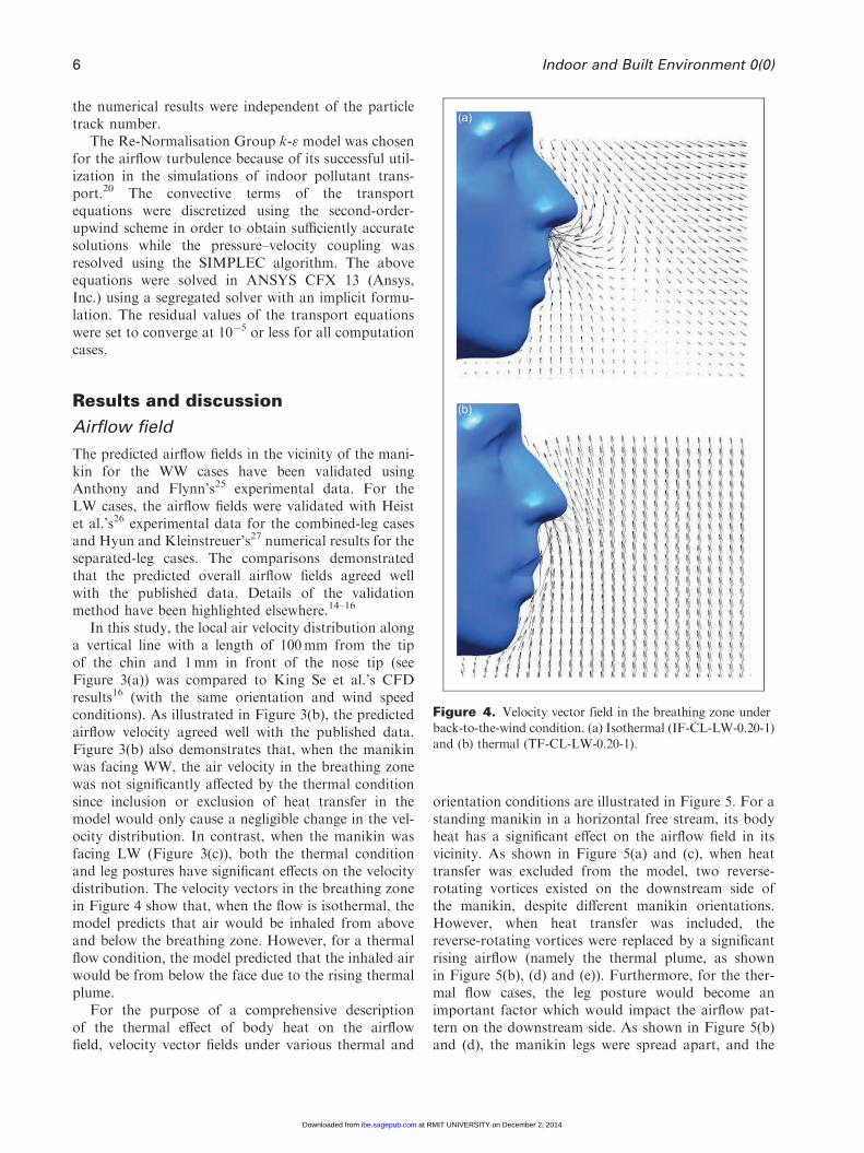
In this study, the local air velocity distribution alonga vertical line with a length of 100mm from the tipof the chin and 1mm in front of the nose tip (seeFigure 3(a)) was compared to King Se et al.’s CFDresults16 (with the same orientation and wind speedconditions). As illustrated in Figure 3(b), the predictedairflow velocity agreed well with the published data.Figure 3(b) also demonstrates that, when the manikinwas facing WW, the air velocity in the breathing zonewas not significantly affected by the thermal conditionsince inclusion or exclusion of heat transfer in themodel would only cause a negligible change in the vel-ocity distribution. In contrast, when the manikin wasfacing LW (Figure 3(c)), both the thermal conditionand leg postures have significant effects on the velocitydistribution. The velocity vectors in the breathing zonein Figure 4 show that, when the flow is isothermal, themodel predicts that air would be inhaled from aboveand below the breathing zone. However, for a thermalflow condition, the model predicted that the inhaled airwould be from below the face due to the rising thermalplume.
For the purpose of a comprehensive descriptionof the thermal effect of body heat on the airflowfield, velocity vector fields under various thermal and
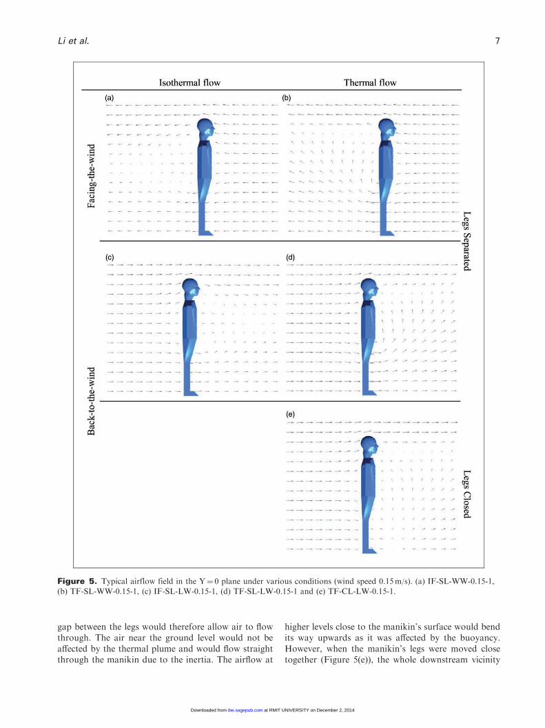
orientation conditions are illustrated in Figure 5. For astanding manikin in a horizontal free stream, its bodyheat has a significant effect on the airflow field in itsvicinity. As shown in Figure 5(a) and (c), when heattransfer was excluded from the model, two reverse-rotating vortices existed on the downstream side ofthe manikin, despite different manikin orientations.However, when heat transfer was included, thereverse-rotating vortices were replaced by a significantrising airflow (namely the thermal plume, as shownin Figure 5(b), (d) and (e)). Furthermore, for the ther-mal flow cases, the leg posture would become animportant factor which would impact the airflow pat-tern on the downstream side. As shown in Figure 5(b)and (d), the manikin legs were spread apart, and the
Figure 4. Velocity vector field in the breathing zone underback-to-the-wind condition. (a) Isothermal (IF-CL-LW-0.20-1)and (b) thermal (TF-CL-LW-0.20-1).
6 Indoor and Built Environment 0(0)
at RMIT UNIVERSITY on December 2, 2014ibe.sagepub.comDownloaded from
XML Template (2014) [8.9.2014–12:49pm] [1–14]//blrnas3/cenpro/ApplicationFiles/Journals/SAGE/3B2/IBEJ/Vol00000/140078/APPFile/SG-IBEJ140078.3d (IBE) [INVALID Stage]
gap between the legs would therefore allow air to flowthrough. The air near the ground level would not beaffected by the thermal plume and would flow straightthrough the manikin due to the inertia. The airflow at
higher levels close to the manikin’s surface would bendits way upwards as it was affected by the buoyancy.However, when the manikin’s legs were moved closetogether (Figure 5(e)), the whole downstream vicinity
Figure 5. Typical airflow field in the Y¼ 0 plane under various conditions (wind speed 0.15m/s). (a) IF-SL-WW-0.15-1,(b) TF-SL-WW-0.15-1, (c) IF-SL-LW-0.15-1, (d) TF-SL-LW-0.15-1 and (e) TF-CL-LW-0.15-1.
Li et al. 7
at RMIT UNIVERSITY on December 2, 2014ibe.sagepub.comDownloaded from
XML Template (2014) [8.9.2014–12:49pm] [1–14]//blrnas3/cenpro/ApplicationFiles/Journals/SAGE/3B2/IBEJ/Vol00000/140078/APPFile/SG-IBEJ140078.3d (IBE) [INVALID Stage]
would be affected by the body heat and a significantrising airflow starting from the floor level would appearin this region. Previous studies have shown that the air-flow arising from the floor can entrain the near-floorcontaminants into the breathing zone.12,26
Therefore, for a thermal manikin standing in a hori-zontal free stream, the flow field thermally affected bythe body heat was located on its downstream side. As aresult, the manikin’s orientation relative to the freestream would be a crucial factor in determining whetherand how much inhalation would be affected by thebody heat. As the manikin was facing WW, its breath-ing zone was located upstream of the thermal plumeand its inhalation was therefore expected to be freefrom the thermal effect. In contrast, when the manikinwas facing the lee side, its breathing zone was in thethermal plume and its inhalation was largely subject toits thermal effect.
Overall characteristics of particleinhalation
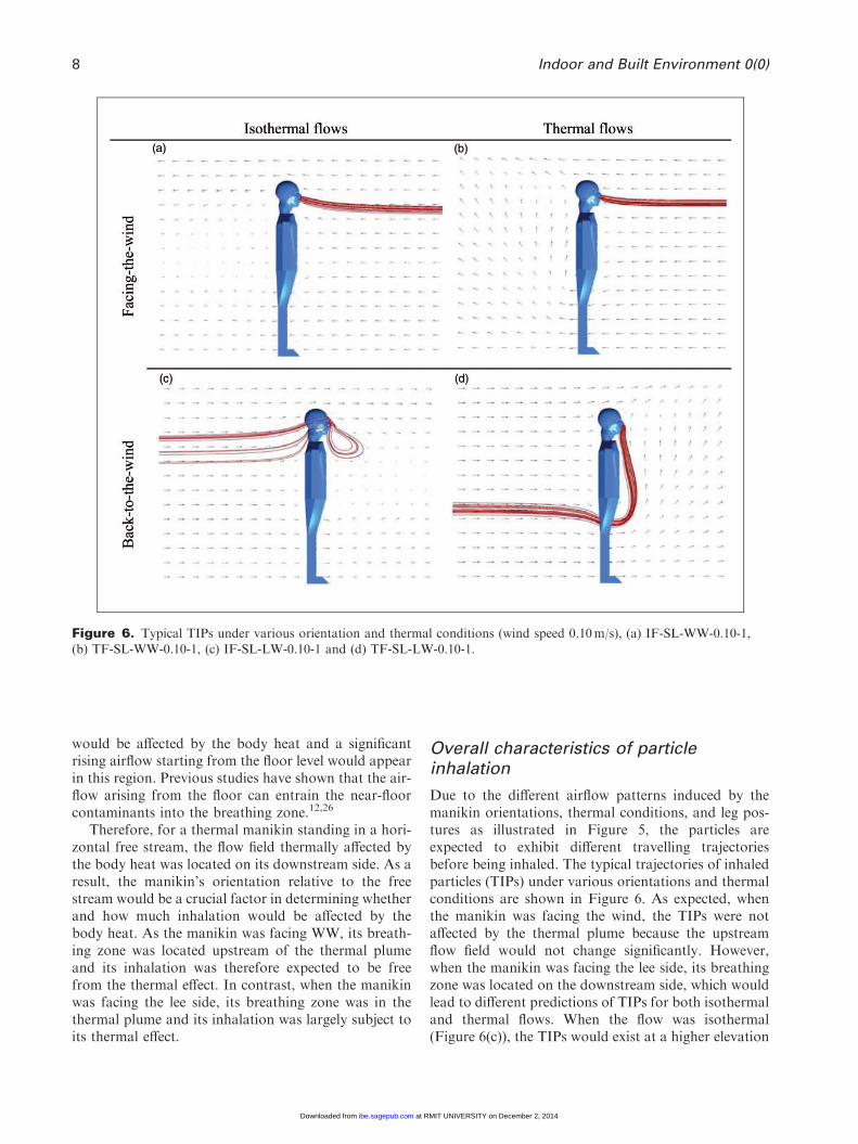
Due to the different airflow patterns induced by themanikin orientations, thermal conditions, and leg pos-tures as illustrated in Figure 5, the particles areexpected to exhibit different travelling trajectoriesbefore being inhaled. The typical trajectories of inhaledparticles (TIPs) under various orientations and thermalconditions are shown in Figure 6. As expected, whenthe manikin was facing the wind, the TIPs were notaffected by the thermal plume because the upstreamflow field would not change significantly. However,when the manikin was facing the lee side, its breathingzone was located on the downstream side, which wouldlead to different predictions of TIPs for both isothermaland thermal flows. When the flow was isothermal(Figure 6(c)), the TIPs would exist at a higher elevation
Figure 6. Typical TIPs under various orientation and thermal conditions (wind speed 0.10m/s), (a) IF-SL-WW-0.10-1,(b) TF-SL-WW-0.10-1, (c) IF-SL-LW-0.10-1 and (d) TF-SL-LW-0.10-1.
8 Indoor and Built Environment 0(0)
at RMIT UNIVERSITY on December 2, 2014ibe.sagepub.comDownloaded from

XML Template (2014) [8.9.2014–12:49pm] [1–14]//blrnas3/cenpro/ApplicationFiles/Journals/SAGE/3B2/IBEJ/Vol00000/140078/APPFile/SG-IBEJ140078.3d (IBE) [INVALID Stage]
around the breathing zone level. However, when heattransfer was included in the model (Figure 6(d)), theTIPs were found at a lower elevation. In the lattercase, the particles would travel nearly horizontallyupstream of the manikin, and then bend their waysupward into the breathing zone as a consequence ofthe thermal plume. From these results, the thermalplumes would be significant for the LW casessince the low velocities would allow buoyancy tohave an effect. Therefore, in the following sections, dis-cussion and analysis will be focused mainly on theLW cases.
Particle inhalation under LW conditions
For an LW thermal manikin with legs separated apart,the TIPs for three different particle sizes at a constantwind speed are shown in Figure 7. The TIPs for 1 mmparticles were transported completely by the thermalplume (Figure 7(a)). With increasing particle size, thegravitational force would gradually come into play andwould reduce the influence of the thermal plume onparticle inhalation. Inhaled 15 mm particles wouldcome from both below and approximately at thebreathing height (Figure 7(b)). When the particle sizewas increased to 25 mm, the effect of gravitational forcewould dominate the thermal plume so that the inhaledparticle trajectories did not exist near the ground, sincethey could not be entrained into the rising plume(Figure 7(c)). Similarly, this flow phenomenon was con-sistent with the increasing wind speed for a constantparticle size. Therefore, increasing the wind speed orparticle size would curtail particle entrainment in thethermal plume.
To determine the thermal effect of body heat on par-ticle inhalation, a dimensionless body thermal effective-ness (’) was defined in this study (equation (5))
’ ¼mp, themal
mp, totalð5Þ
where mp, themal is the mass of inhaled particles which areentrained upwards into the nostrils by the thermal plumeand mp,total is the total mass of inhaled particles, respect-ively. Referring to Figure 7, mp, themal represents the massof the particles moving up to the breathing zone.Obviously, when ’ ¼ 1, the inhaled particles would beall entrained by the thermal plume from a lower height(Figure 7(a)). When ’ ¼ 0, no inhaled particles could beentrained by the thermal plume, and the forced convec-tion and gravitational force would dominate the thermalplume (Figure 7(c)). Finally, 05 ’5 1 means theinhaled particles would be released from both higherand lower heights (Figure 7(b)) as caused by a combin-ation of all three influences.
Figure 8(a) and (b) illustrates the body thermaleffectiveness as a function of wind speed and particlesize under conditions when the manikin’s legs areclosed and separated. When the thermal manikin wasstanding LW, the body thermal effectiveness would
Figure 7. Typical TIP patterns under leeward and thermalconditions. (a) Thermal control (TF-SL-LW-0.20-1, 1mm),(b) partially thermal control (TF-SL-LW-0.20-15, 15 mm),
(c) none thermal control (TF-SL-LW-0.20-25, 25 mm).
Li et al. 9
at RMIT UNIVERSITY on December 2, 2014ibe.sagepub.comDownloaded from

XML Template (2014) [8.9.2014–12:49pm] [1–14]//blrnas3/cenpro/ApplicationFiles/Journals/SAGE/3B2/IBEJ/Vol00000/140078/APPFile/SG-IBEJ140078.3d (IBE) [INVALID Stage]
remain unchanged (’ ¼ 1) when the wind speed is lowand the particle size is small, regardless of leg posture.This indicates that the body heat has a predominantrole in these parametric ranges. Further analysisdemonstrated that, under low wind speed conditions(0.05m/s, Figure 9(a)), the thermal plume generatedby the body heat would have a large momentum (com-pared with the free stream) that it can entrain particlesas large as 25 mm in diameter into the breathing zonedespite the increased gravitational settlement on the
upstream side of the manikin. Analysis also suggestedthat, for small-size particles (1mm, Figure 9(b)), theeffect of gravity would be mostly negligible andtheir movements are predominantly controlled by theairflow. With increasing wind speed and larger vortexsize on the downstream side of the manikin (Figure 5),particles would travel through longer distances beforebeing inhaled.
The body thermal effectiveness in Figure 8 also sug-gests that ’ would generally decrease with an increase
Figure 8. Body thermal effectiveness under leeward conditions. (a) Legs closed together and (b) legs separated apart.
10 Indoor and Built Environment 0(0)
at RMIT UNIVERSITY on December 2, 2014ibe.sagepub.comDownloaded from

XML Template (2014) [8.9.2014–12:49pm] [1–14]//blrnas3/cenpro/ApplicationFiles/Journals/SAGE/3B2/IBEJ/Vol00000/140078/APPFile/SG-IBEJ140078.3d (IBE) [INVALID Stage]
in wind speed or particle size. In this region, differentleg postures would lead to different body thermal effect-iveness. The results showed that the body thermaleffectiveness ’ would be more sensitive to the windspeed when the legs were close together. On the otherhand, the wind speed and particle size were shown tohave equal importance when the legs were spread apart.As shown in Figure 8(a), when the legs were closetogether, ’ was reduced sharply until the wind speedreached 0.25m/s, at which the thermal plume could notentrain any particles into the nostrils within the particlesize range investigated. On the other hand, when thelegs were parted (Figure 8(b)), the thermal plume wouldbe able to entrain particles up to 20 mm into the breath-ing zone even when the wind speed reached 0.25m/s.
(a)
(c)
Figure 9. Particle inhalation characteristics when ’¼1.(a) Low wind speed (0.05m/s) and (b) small particle size
(1 mm). (Note: For the purpose of clearer comparison, theTIPs yielded from a computational case were simplified into arepresentative particle track, which was obtained by aver-
aging all the TIPs. The manikin was included to illustrate thetrack locations relative to the manikin only in the height (Z)coordinate. The manikin size in the Y and X coordinates isnot proportional with the coordinate scale. This note also
applies to Figure 11.)
Figure 10. Comparison of airflow field and particletrajectories for different leg postures. (a) Legs closed together(TH-CL-LW-0.25-1, 0.25m/s), (b) legs separated apart
(TH-SL-LW-0.25-1, 0.25m/s).
Figure 11. Typical critical areas under leeward cases
(1-mm particles).
Li et al. 11
at RMIT UNIVERSITY on December 2, 2014ibe.sagepub.comDownloaded from
XML Template (2014) [8.9.2014–12:49pm] [1–14]//blrnas3/cenpro/ApplicationFiles/Journals/SAGE/3B2/IBEJ/Vol00000/140078/APPFile/SG-IBEJ140078.3d (IBE) [INVALID Stage]
A comparison of the airflow field and particle tra-jectories under the higher wind speed (0.25m/s) mayinterpret this difference. Figure 10(a) shows that, whenthe manikin was standing with its legs close together,there were two reverse-rotating vortices on the down-stream side of the manikin. The lower vortex wouldentrain particles from near the floor level to a higherlevel while the upper vortex would deliver particlesfrom the head level to a lower level. As the windspeed was increased, the upper vortex would expandand suppress the lower one. When the wind speed wasincreased to 0.25m/s, the size of the upper vortexwould be large enough so that the lower vortexcould no longer deliver particles into the breathingzone. When the legs were parted, the horizontal air-flow through the gap would lead to a large vortex nearthe ground. This lower vortex would expand its size
with increasing wind speed and thus would enhance itsability to deliver particles into the breathing zone fromlower levels.
The critical area
As shown in Figure 6, although particles were injectedfrom a large area (1.6m in diameter, Figure 1), onlythose released in a certain small area were inhaled. Thisarea from which inhaled particles were released wasdefined as the ‘critical area’ by Anthony and Flynn.25
The critical areas under WW conditions have beenhighlighted in our previous publications.14–16 For theLW conditions, typical critical areas are illustrated inFigure 11. The location and shape of the critical areaare highly sensitive to heat transfer and leg posture. Thecritical area for the thermal flow, TF, is much lowerthan that for the IF. The findings show that the mani-kin leg posture has a significant effect on the geometryand location of the critical area. When the manikin’slegs were spread in an open position, particles wouldmove with the air through the gap between the legs sothat the critical area would become a triangle, and takethe geometry of the upper part of the gap. However,when the legs were together in a close position (i.e. CL),particles would travel around the legs before beingentrained upwards so that the critical area would beseparated into two sub-areas, one on the left side andthe other on the right side.
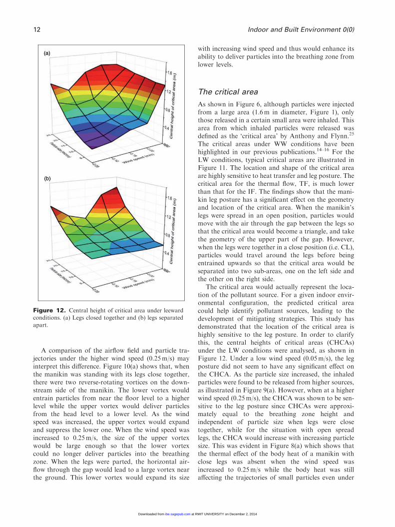
The critical area would actually represent the loca-tion of the pollutant source. For a given indoor envir-onmental configuration, the predicted critical areacould help identify pollutant sources, leading to thedevelopment of mitigating strategies. This study hasdemonstrated that the location of the critical area ishighly sensitive to the leg posture. In order to clarifythis, the central heights of critical areas (CHCAs)under the LW conditions were analysed, as shown inFigure 12. Under a low wind speed (0.05m/s), the legposture did not seem to have any significant effect onthe CHCA. As the particle size increased, the inhaledparticles were found to be released from higher sources,as illustrated in Figure 9(a). However, when at a higherwind speed (0.25m/s), the CHCA was shown to be sen-sitive to the leg posture since CHCAs were approxi-mately equal to the breathing zone height andindependent of particle size when legs were closetogether, while for the situation with open spreadlegs, the CHCA would increase with increasing particlesize. This was evident in Figure 8(a) which shows thatthe thermal effect of the body heat of a manikin withclose legs was absent when the wind speed wasincreased to 0.25m/s while the body heat was stillaffecting the trajectories of small particles even under
Figure 12. Central height of critical area under leewardconditions. (a) Legs closed together and (b) legs separated
apart.
12 Indoor and Built Environment 0(0)
at RMIT UNIVERSITY on December 2, 2014ibe.sagepub.comDownloaded from
XML Template (2014) [8.9.2014–12:49pm] [1–14]//blrnas3/cenpro/ApplicationFiles/Journals/SAGE/3B2/IBEJ/Vol00000/140078/APPFile/SG-IBEJ140078.3d (IBE) [INVALID Stage]
such a high wind speed if the legs are parted(Figure 8(b)). Figure 12 also reveals that the thermaleffect of the body heat on CHCA is significant when theparticle size is small. The CHCA of 1 mm particleswould increase with increasing wind speed when thelegs were close together but was almost unchangedwhen the legs were spread open.
On the other hand, Figure 12 demonstrates that thebody heat has no significant effect on CHCA forlarger particles. Figure 12(a) and (b) suggests that, for25 mm particles, an increasing wind speed wouldreduce the CHCA. This is due to the declining entrain-ment capability of the thermal plume, as illustratedin Figure 7.
In conclusion, for a thermal manikin standing LW,its leg posture could strongly affect the source locationof inhaled particles when the wind speed is high or theparticle size is small. Therefore, when the effect of air-flow dominates the particle motion, the particle inhal-ation characteristics would be strongly affected by theleg posture.
Conclusions
The particle inhalation characteristics of a manikinstanding in a horizontal airflow were numerically inves-tigated using CFD. Computations were conducted withdifferent environment conditions including wind speed,particle size, manikin’s orientation and leg posture.Conclusions arising from this study include:
1. For a thermal manikin standing in a free air stream,the airflow field is thermally affected by the bodyheat on its downstream side, which makes its orien-tation relative to the free stream an important factordeciding whether and how much its inhalation char-acteristics would be affected by its body thermalplume. When the manikin is facing the wind, thethermal effect of its body heat could be neglected.However, when the manikin is facing the lee side, thethermal plume can entrain near-floor pollutants intothe breathing zone and the inhaled particles are actu-ally originated from a source at a lower elevation.
2. When the manikin is facing the lee side, its leg pos-ture is an important factor affecting the characteris-tics of particle inhalation. Different leg postures havedifferent environment sensitivities, which is espe-cially true when the particle size is small or thewind speed is high.
3. Quantitative description of the effects of the bodyheat on particle inhalation under various conditionswas achieved (Figures 8 and 12), which can provideuseful information for health risk assessment asso-ciated with inhalation exposure to particulate matterand particle-borne contaminants.
Authors’ contributions
XL conducted the numerical simulations, analysed the results
and then drafted the manuscript. KI helped analyse theresults and also contributed to the drafting. JT is the super-visor of the research project. He gave important adviceson the simulations, and provided the overall review of the
paper writing.
Declaration of conflicting interests
XL, KI and JT declare that they have no proprietary, finan-
cial, professional or other personal interest of any nature orkind in any product, service and/or company that could beconstrued as influencing the position presented in, or the
review of, this research paper.
Funding
This study was financially supported by the National
Basic Research Program (973) of China (Grant No.2012CB720100), the Australian Research Council (projectID LP110100140) and the Natural Science Foundation of
China (Grant No. 21277080).
References
1. Klepeis NE, Nelson WC, Ott WR, Robinson JP, Tsang AM,
Switzer P, Behar JV, Hern SC and Engelmann WH. The national
human activity pattern survey (NHAPS): a resource for assessing
exposure to environmental pollutants. J Expos Analy Environ
Epid 2001; 11: 231–252.
2. Armendariz-Arnez C, Edwards RD, Johnson M, Rosas IA,
Espinosa F and Masera OT. Indoor particle size distribution in
homes with open fires and improved Patsari cook stoves. Atmos
Environ 2010; 44: 2881–2886.
3. Rothman RE, Hsieh YH and Yang S. Communicable respiratory
threats in the ED: tuberculosis, influenza, SARS, and other aero-
solized infections. Emerg Med Clin N Am 2006; 24: 989–1017.
4. Ormstad H. Suspended particulate matter in indoor air: adju-
vants and allergen carriers. Toxicology 2000; 152: 53–68.
5. Zukowska D, Popiolek Z and Melikov A. Impact of personal
factors and furniture arrangement on the thermal plume above
a human body. In: Proceedings of the 10th international confer-
ence on air distribution in rooms – roomvent 2007. Helsinki,
Finland, June 13–15 2007; pp.137–144.
6. Gao NP and Niu JL. CFD study on micro-environment around
human body and personalized ventilation. Build Environ 2004;
39: 795–805.
7. Menache MG, Miller FJ and Raabe OG. Particle inhalability
curves for humans and small laboratory-animals. Ann Occup
Hyg 1995; 39: 317–328.
8. Anthony TR and Flynn MR. Computational fluid dynamics
investigation of particle inhalability. J Aerosol Sci 2006; 37:
750–765.
9. He QB, Niu JL, Gao NP, Zhu T and Wu JZ. CFD study of
exhaled droplet transmission between occupants under different
ventilation strategies in a typical office room. Build Environ 2011;
46: 397–408.
10. Zhao B, Yang CQ, Chen C, Feng C, Yang XD, Sun LC, Wei G
and Li Y. How many airborne particles emitted from a nurse will
reach the breathing zone/body surface of the patient in ISO class-
5 single-bed hospital protective environments? – A numerical
analysis. Aerosol Sci Tech 2009; 43: 990–1005.
Li et al. 13
at RMIT UNIVERSITY on December 2, 2014ibe.sagepub.comDownloaded from
XML Template (2014) [8.9.2014–12:49pm] [1–14]//blrnas3/cenpro/ApplicationFiles/Journals/SAGE/3B2/IBEJ/Vol00000/140078/APPFile/SG-IBEJ140078.3d (IBE) [INVALID Stage]
11. Salmanzadeh M, Zahedi G, Ahmadi G, Marr DR and Glauser
M. Computational modeling of effects of thermal plume adjacent
to the body on the indoor airflow and particle transport.
J Aerosol Sci 2012; 53: 29–39.
12. Rim D and Novoselac A. Transport of particulate and gaseous
pollutants in the vicinity of a human body. Build Environ 2009;
44: 1840–1849.
13. Spitzer IM, Marr DR and Glauser MN. Impact of manikin
motion on particle transport in the breathing zone. J Aerosol
Sci 2010; 41: 373–383.
14. Ge QJ, Li XD, Inthavong K and Tu JY. Numerical study of the
effects of human body heat on particle transport and inhalation
in indoor environment. Build Environ 2013; 59: 1–9.
15. Li XD, Inthavong K and Tu JY. Particle inhalation and depos-
ition in a human nasal cavity from the external surrounding
environment. Build Environ 2012; 47: 32–39.
16. King Se CM, Inthavong K and Tu JY. Inhalability of micron
particles through the nose and mouth. Inhal Toxicol 2010; 22:
287–300.
17. Kurazumi Y, Tsuchikawa T, Ishii J, Fukagawa K, Yamato Y
and Matsubara N. Radiative and convective heat transfer coef-
ficients of the human body in natural convection. Build Environ
2008; 43: 2142–2153.
18. Tilley AR. The measure of man and woman. New York: The
Whitney Library of Design, 1993.
19. Brohus H and Nielsen PV. CFD models of persons evaluated by
full-scale wind channel experiments. In: Proceedings of roomvent
96, the 5th international conference on air distribution in rooms,
Yokohama, Japan, July 17–19 1996; pp.137–144.
20. Gao NP and Niu JL. CFD study of the thermal environment
around a human body: a review. Indoor Built Environ 2005; 14:
5–16.
21. Baldwin PEJ and Maynard AD. A survey of wind speeds in
indoor workplaces. Ann Occup Hyg 1998; 42: 303–313.
22. Kennedy NJ and Hinds WC. Inhability of large solid particles.
J Aerosol Sci 2002; 33: 237–255.
23. Horschler I, Schroder W and Meinke M. On the assump-
tion of steadiness of nasal cavityflow. J Biomech 2010; 43:
1081–1085.
24. Zhao B, Zhang Y, Li XT, Yang XD and Huang DT. Comparison
of indoor aerosol particle concentration and deposition in differ-
ent ventilated rooms by numerical method. Built Environ 2004;
39: 1–8.
25. Anthony TR and Flynn MR. Computational fluid dynamics
investigation of particle inhability. J Aerosol Sci 2006; 37:
750–765.
26. Heist DK, Eisner AD, Mitchell W andWiener R. Airflow around
a child-size manikin in a low-speed wind environment. Aerosol
Sci Tech 2003; 37: 303–314.
27. Hyun S and Kleinstreuer C. Numerical simulation of mixed con-
vection heat and mass transfer in a human inhalation test cham-
ber. Int J Heat Mass Tran 2001; 44: 2247–2260.
14 Indoor and Built Environment 0(0)
at RMIT UNIVERSITY on December 2, 2014ibe.sagepub.comDownloaded from
Related Documents