NUMERICAL ANALYSIS OF A DOWNSIZED 2-STROKE UNIFLOW ENGINE J. Ma, Cho-Yu Lee, H. Zhao, J. Xia, Brunel University London M. Hawley, SMTC P. Freeland, Mahle Powertrain Technology Abstract Engine dowsizing is one of the most effective means to achieve the reduction in fuel consumption and CO2 emissions from passenger cars. All engine downsizing so far has been achieved through the replacement of a NA 4- stroke engine with another 4-stroke boosted engine. In order to achieve further engine downsizing and downspeeding, the 2-stroke uniflow direct injection gasoline engine was studied as a potential candidate for future vehicle applications. In order to optimize the 2- stroke uniflow engine performance, systematic studies were performed on the intake port design, engine geometry, and scavenging events by means of combined 3-D CFD flow analysis and 1-D engine simulation programme. This is followed by the investigation on the boost system optimization and the engine configuration for a typical passenger car. The results show that a 0.6litre 2-cylinder 2-stroke uniflow engine can be used to replace a modern 1.6litre 4-cylinder NA gasoline engine in a typical passenger car vehicle with potential improvement in performance, drivability and fuel economy. Introduction Aggressive downsizing of four-stroke gasoline engines at 50% has been recently published by a number of companies claiming fuel savings of 25%. Downsizing to 50% and beyond presents severe challenges e.g. maximum boost capability, knocking combustion, transient performance, high peak cylinder pressure and associated mechanical and thermal load issues. As the 2- stroke cycle doubles the firing frequency of the 4- stroke cycle, for the same torque output the 2- stroke engine IMEP and the peak pressure are approximately halved and the safety margin from combustion knock is wider. Thus, the 2-stroke cycle engine has the potential to achieve aggressive downsizing without having to significantly strengen the engine’s design, dispensing with the need for ulta-high boost, and avoiding knocking combustion. The uniflow is known as the most efficient scavenging method for the 2-stroke cycle operation . Also, the uniflow 2-stroke engine can be operated at high boost by closing the exhaust valves earlier and uses proven wet sump and poppet valve technology. The uniflow 2-stroke engine avoids bore distortion caused by uneven thermal loading in the conventional ported 2- stroke engine with its cold intake port on one side and hot exhaust port on the other. Furthermore, the uniflow 2-stroke engine is by nature very suitable for CAI combustion operation which gives stable and fuel efficient part-load operation by adjusting the scavenging efficiency and hot residual gases through phasing of the poppet exhaust valves using VCT (variable cam timing) devices. Using CAI addresses the unstable part load combustion often experieneced by the 2-stroke spark ignition gasoline engine resulting in much reduced uHC

Welcome message from author
This document is posted to help you gain knowledge. Please leave a comment to let me know what you think about it! Share it to your friends and learn new things together.
Transcript
NUMERICAL ANALYSIS OF A DOWNSIZED 2-STROKE UNIFLOW ENGINE
J. Ma, Cho-Yu Lee, H. Zhao, J. Xia, Brunel University London
M. Hawley, SMTC
P. Freeland, Mahle Powertrain Technology
Abstract
Engine dowsizing is one of the most effective means to achieve the reduction in fuel consumption and CO2 emissions from passenger cars. All engine downsizing so far has been achieved through the replacement of a NA 4-stroke engine with another 4-stroke boosted engine. In order to achieve further engine downsizing and downspeeding, the 2-stroke uniflow direct injection gasoline engine was studied as a potential candidate for future vehicle applications. In order to optimize the 2-stroke uniflow engine performance, systematic studies were performed on the intake port design, engine geometry, and scavenging events by means of combined 3-D CFD flow analysis and 1-D engine simulation programme. This is followed by the investigation on the boost system optimization and the engine configuration for a typical passenger car. The results show that a 0.6litre 2-cylinder 2-stroke uniflow engine can be used to replace a modern 1.6litre 4-cylinder NA gasoline engine in a typical passenger car vehicle with potential improvement in performance, drivability and fuel economy.
Introduction
Aggressive downsizing of four-stroke gasoline engines at 50% has been recently published by a number of companies claiming fuel savings of 25%. Downsizing to 50% and beyond presents
severe challenges e.g. maximum boost capability, knocking combustion, transient performance, high peak cylinder pressure and associated mechanical and thermal load issues. As the 2-stroke cycle doubles the firing frequency of the 4-stroke cycle, for the same torque output the 2-stroke engine IMEP and the peak pressure are approximately halved and the safety margin from combustion knock is wider. Thus, the 2-stroke cycle engine has the potential to achieve aggressive downsizing without having to significantly strengen the engine’s design, dispensing with the need for ulta-high boost, and avoiding knocking combustion.
The uniflow is known as the most efficient scavenging method for the 2-stroke cycle operation . Also, the uniflow 2-stroke engine can be operated at high boost by closing the exhaust valves earlier and uses proven wet sump and poppet valve technology. The uniflow 2-stroke engine avoids bore distortion caused by uneven thermal loading in the conventional ported 2-stroke engine with its cold intake port on one side and hot exhaust port on the other. Furthermore, the uniflow 2-stroke engine is by nature very suitable for CAI combustion operation which gives stable and fuel efficient part-load operation by adjusting the scavenging efficiency and hot residual gases through phasing of the poppet exhaust valves using VCT (variable cam timing) devices. Using CAI addresses the unstable part load combustion often experieneced by the 2-stroke spark ignition gasoline engine resulting in much reduced uHC
and CO emissions, better fuel economy and significantly lower NOx emissions [1].
Compared to the 2-stroke engine with poppet inlet and exhaust valves, a uniflow 2-stroke engine produces better scavenging, minimum short circuiting and can have a centrally mounted injector for optimal combustion, even for small bore sizes. Combining GDI and uniflow layout, means the air and fuel short-circuiting associated with conventional two-stroke SI engines can be avoided.
2-stroke uniflow engines are widely used in large marine diesel engines and in some diesel locomotives. Detroit Diesel had been manufacturing uniflow 2-stroke direct injection diesel engines for heavy duty vehicles until late 1990s as well as for military vehicles requiring very high power density engines. In the late 1990s, prototype 2-storke uniflow diesel engines were built [2- 4] and some numerical analyses were performed on the gas scavenging process [5, 6].
In this work, a 3-D CFD engine model has been set up to investigate the scavenging process of a downsized boosted 2-stroke uniflow engine. A 1-D numerical model has also been buit up for the purpose of engine performance prediction.
Scavenging process optimization
The performance of the 2-storke engine is largely determined by the scavenging process during the overlap period of intake and exhaust openning. There are mainly 3 ways to scavenge a 2-stroke engine, crossflow, loopflow, and uniflow. Among these methods, the uniflow method shows the best scavenging efficiency [7]. In a uniflow 2-stroke engine, intake ports geometry and opening time determines the intake fresh charge mass flow rate, the scavenging performance, and the swirl generation of in-cylinder flow.
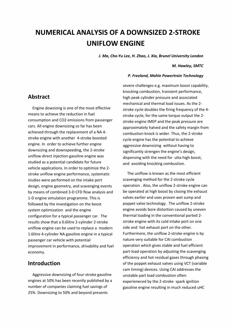
At the start of the project, a single cylinder 2-stroke uniflow engine model was set up for the study of scavenging process and the optimised design of the intake ports. The engine model features intake ports at the bottom of cylinder liner. Exhaust valves are included in cylinder head and actuated by a camshaft. A set of parameters are introduced [8] to define the intake port configuration settings of the 2-stroke uniflow engine, as shown in Figure 1 and Table 1.
(a)
(b) Figure. 1 The intake port geometry parameter
Table 1 The intake port geometry parameter Parameter Definition
rcy engine bore
rp radius of swirl circle θp port width angle N Number of ports Ai Axis inclination angle φp Swirl orientation angle
= 90°− cos−1(rcy 𝑟𝑝⁄ ) − 𝜃𝑝 2⁄ xp Effective port width
= 2 × sin(𝜃𝑝/2) × cosφ𝑝 θb Port shoulder width angle
= 360 𝑁⁄ − 𝜃𝑝 xb Effective port shoulder width
= 2 × rcy × sin𝜃𝑏 2⁄
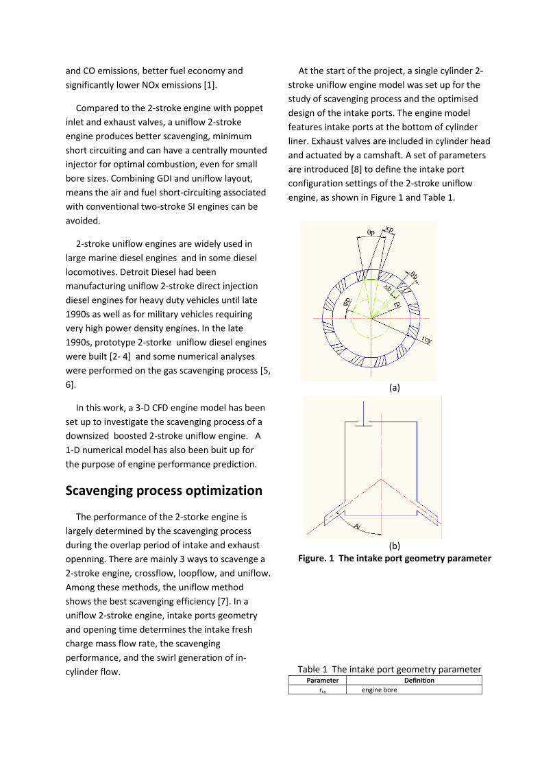
In order to set a ground for simulation work, a 2-D model was first used to predict the effect of axis inclination angle, Ai, on in-cylinder flow and the scavenging process during the overlap period of intake port opening and exhaust valve opening. The 2-D model is shown in Figure 2.
Figure. 2 The 2-D CFD model
The following parameters are used to characterise the quality of scavenging process [9]:
(i.) Delivery ratio (DR): defined as the ratio of delivered fresh charge mass to reference mass. The reference mass is calculated by the displaced volume multiplied by ambient air density.
(ii.) Trapping efficiency (TE): defined as the ratio of mass of delivered fresh charge retained in the in-cylinder to the total mass of delivered fresh charge.
(iii.) Scavenging efficiency (SE): defined as the ratio of mass of delivered fresh charge retained in the cylinder to the total trapped cylinder charge.
(iv.) Charging efficiency (CE): defined as the ratio of mass of delivered air retained in the cylinder to the reference mass.
The calculations started from 120°ATDC, at which exhaust valves start to open, to 250°ATDC, when the intake ports are fully covered by the piston. A 1.5bar absolute boost pressure was applied to the intake flow. The initial in-cylinder pressure was set to 1.2bar @120°ATDC, and in-cylinder temperature was set to 500K. The initial in-cylinder charge was assumed to be stationary. The exhaust backpressure was set at the ambient pressure.
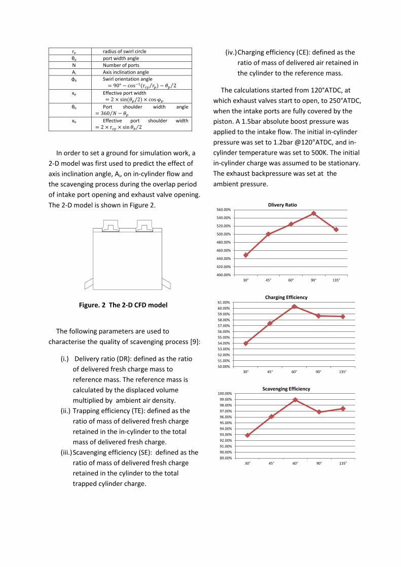
400.00%
420.00%
440.00%
460.00%
480.00%
500.00%
520.00%
540.00%
560.00%
30° 45° 60° 90° 135°
Dlivery Ratio
50.00%51.00%52.00%53.00%54.00%55.00%56.00%57.00%58.00%59.00%60.00%61.00%
30° 45° 60° 90° 135°
Charging Efficiency
89.00%90.00%91.00%92.00%93.00%94.00%95.00%96.00%97.00%98.00%99.00%
100.00%
30° 45° 60° 90° 135°
Scavenging Efficiency
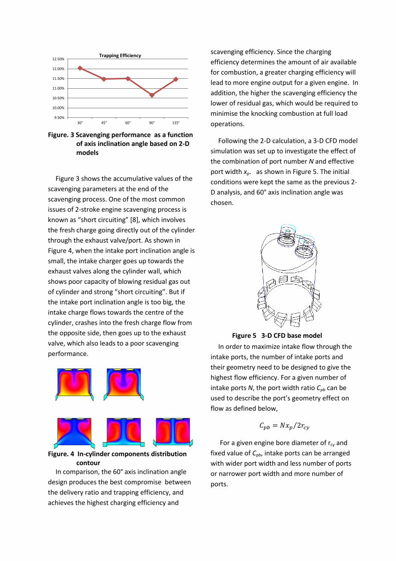
Figure. 3 Scavenging performance as a function
of axis inclination angle based on 2-D models
Figure 3 shows the accumulative values of the scavenging parameters at the end of the scavenging process. One of the most common issues of 2-stroke engine scavenging process is known as “short circuiting” [8], which involves the fresh charge going directly out of the cylinder through the exhaust valve/port. As shown in Figure 4, when the intake port inclination angle is small, the intake charger goes up towards the exhaust valves along the cylinder wall, which shows poor capacity of blowing residual gas out of cylinder and strong “short circuiting”. But if the intake port inclination angle is too big, the intake charge flows towards the centre of the cylinder, crashes into the fresh charge flow from the opposite side, then goes up to the exhaust valve, which also leads to a poor scavenging performance.
Figure. 4 In-cylinder components distribution
contour In comparison, the 60° axis inclination angle
design produces the best compromise between the delivery ratio and trapping efficiency, and achieves the highest charging efficiency and
scavenging efficiency. Since the charging efficiency determines the amount of air available for combustion, a greater charging efficiency will lead to more engine output for a given engine. In addition, the higher the scavenging efficiency the lower of residual gas, which would be required to minimise the knocking combustion at full load operations.
Following the 2-D calculation, a 3-D CFD model simulation was set up to investigate the effect of the combination of port number N and effective port width xp. as shown in Figure 5. The initial conditions were kept the same as the previous 2-D analysis, and 60° axis inclination angle was chosen.
Figure 5 3-D CFD base model
In order to maximize intake flow through the intake ports, the number of intake ports and their geometry need to be designed to give the highest flow efficiency. For a given number of intake ports N, the port width ratio Cpb can be used to describe the port’s geometry effect on flow as defined below,
𝐶𝑝𝑏 = 𝑁𝑥𝑝 2𝑟𝑐𝑦⁄
For a given engine bore diameter of rcy and fixed value of Cpb, intake ports can be arranged with wider port width and less number of ports or narrower port width and more number of ports.
9.50%
10.00%
10.50%
11.00%
11.50%
12.00%
12.50%
30° 45° 60° 90° 135°
Trapping Efficiency

Different combinations of N and xp were evaluated as given in Table 2 and the definition of each parameter can be found in Table 1.
Table 2 The setting of combination of N and xp Setting SET1 SET 2 SET 3 SET 4 SET 5
rcy – mm 80 80 80 80 80
rp – mm 40 45.7 51.4 55.5 61.2
φp – ° 20 20 20 20 20
θp – ° 20 30 40 48 60
θb – ° 10 15 20 24 30
xb – mm 13.94 20.88 27.78 33.27 41.41
xp – mm 26.12 38.96 51.44 61.20 75.24
N 12 8 6 5 4
Ai – ° 60 60 60 60 60
Cpb 1.9 1.9 1.9 1.9 1.9
For all calculations, the swirl orientation angle was set to 20°, the port width ratio was fixed to 1.9. The number of ports decreased whilst the width of individual ports was enlarged from Set 1 design to Set 5 design.
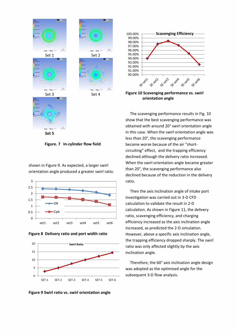
As shown in Figure 6, the air mass flow rate through intake ports wasindependent of the number of intake ports when the port width ratio was kept constant. For a given swirl orientation angle, the swirl ratio decreased slightly as the number of ports was reduced. That is, a higher swirl ratio can be obtained with a larger number of narrower ports due to high flow velocity and better swirl quality as shown in Figure7.
Figure 6 Mass flow rate of intake ports and
swirl ratio
One of the advantages of uniflow scavenging method is its ability to generate strong swirling flow in the cylinder by optimising the intake ports swirl orientation angle φp. Table 3 shows the 6 different sets of intake configurations used to investigate the effect of intake ports swirl orientation angle φp.
Table. 3 Swirl orientation angles φp
Setting SET 1 SET 2 SET 3 SET 4 SET 5 SET 6
rcy – mm 80 80 80 80 80 80
rp – mm 20 30 40 50 60 70
φp – ° 4.43 11.98 19.95 28.64 38.54 51.00
θp – ° 20 20 20 20 20 20
θb – ° 10 10 10 10 10 10
xb – mm 13.94 13.94 13.94 13.94 13.94 13.94
xp – mm 27.70 27.18 26.12 24.39 21.73 17.49
N 12 12 12 12 12 12
Ai – ° 60 60 60 60 60 60
Cpb 1.73 1.70 1.63 1.52 1.36 1.09
As shown in Figure 8, when the swirl orientation angle was increased from 4.43o in Set 1 to 51o in Set 6, the delivery ratio dropped gradually from 2.4 to 1.9 whilst the port width ratio had to be reduced to achieve the increased swirl orientation angle. The results of swirl ratio [9] under different swirl orientation angles are
0.0850.0860.0870.0880.089
0.090.0910.0920.0930.0940.095
Set1 Set2 Set3 Set4 Set5
Mass Flow Rate of Intake Ports
4.5
4.7
4.9
5.1
5.3
5.5
5.7
5.9
Set1 Set2 Set3 Set4 Set5
Swirl Ratio
0
0.5
1
1.5
2
2.5
3
set1 set2 set3 set4 set5 set6
DR
Cpb
shown in Figure 9. As expected, a larger swirl orientation angle produced a greater swirl ratio.
Figure 8 Delivery ratio and port width ratio
Figure 9 Swirl ratio vs. swirl orientation angle
Figure 10 Scavenging performance vs. swirl
orientation angle
The scavenging performance results in Fig. 10 show that the best scavenging performance was obtained with around 20° swirl orientation angle in this case. When the swirl orientation angle was less than 20°, the scavenging performance became worse because of the air “short-circuiting” effect, and the trapping efficiency declined although the delivery ratio increased. When the swirl orientation angle became greater than 20°, the scavenging performance also declined because of the reduction in the delivery ratio.
Then the axis inclination angle of intake port investigation was carried out in 3-D CFD calculation to validate the result in 2-D calculation. As shown in Figure 11, the delivery ratio, scavenging efficiency, and charging efficiency increased as the axis inclination angle increased, as predicted the 2-D simulation. However, above a specific axis inclination angle, the trapping efficiency dropped sharply. The swirl ratio was only affected slightly by the axis inclination angle.
Therefore, the 60° axis inclination angle design was adopted as the optimised angle for the subsequent 3-D flow analysis.
90.00%91.00%92.00%93.00%94.00%95.00%96.00%97.00%98.00%99.00%
100.00% Scavenging Efficiency
Set 1 Set 2
Set 3 Set 4
Set 5
Figure. 7 In-cylinder flow field
0
5
10
15
20
SET-1 SET-2 SET-3 SET-4 SET-5 SET-6
Swirl Ratio

Figure 11 3-D analysis of the effect of axis
inclination angle
Engine Performance Analysis
2-stroke uniflow engine model
To investigate the engine performance, such as the brake power, brake torque and fuel
consumption, a 1-D 2-stroke uniflow engine model was built up using Ricado WAVE .
Figure 12 The timing sequence of 2-stroke operation
The intake flow coefficient in the 1-D engine model was calibrated against the mass flow rate obtained from the 3-D CFD calculations. The flow coefficient was adjusted in the 1-D engine model until the same gas mass flow rate was obtained as the 3-D calculation. As a scavenging profile was required to calculate the residual gas fraction of the 2-stroke engine operation, it was adjusted to produce the same predicted scavenging efficiency as the one obtained from the 3-D CFD calculations.
Once the validation of gas-exchanging performance of the 2-stroke engine operation was completed, the fuel mass flow rate was set to the stoichiometric air to fuel ratio of 14.7:1. The spark ignition Wiebe heat release model was used to describe the combustion process, in which the combustion duration (10% to 90% mass fraction burned) was set to 31°CA. The 50% mass fraction burned angle, CA50, was varied to control the combustion phase. Figure 12 shows the timing sequence of the 2-stroke cycle operation. The intake port opening and closing
135%137%139%141%143%145%147%149%151%153%155%
45° 60° 75° 90°Axis Inclination Angle
Delivery Ratio
58%59%60%61%62%63%64%65%66%67%68%
45° 60° 75° 90°
Axis Inclination Angle
Charging Efficiency
80%
82%
84%
86%
88%
90%
92%
94%
45° 60° 75° 90°
Axis Inclination Angle
Scavenging Effeciency
43.7%
43.8%
43.9%
44.0%
44.1%
44.2%
44.3%
44.4%
44.5%
44.6%
45° 60° 75° 90°Axis Inclination Angle
Trapping Effeciency

are represented by IPO and IPC respectively and DIP is the duration of intake ports opening. The exhaust valves open at EVO and closes at EVC and DEV is the duration of exhaust valves opening period. The period between EVO and IPO defines the blow-down duration, BDD. Fuel was injected directly into the cylinder after both the intake ports and exhaust valves so that the fuel short-circuiting was avoided.
Effect of Engine Geometry on Performance
The first series of 1-D engine performance simulation studies started from the case with absolute boost pressure of 2bar, engine speed of 4000rpm and CA50 at 5°ATDC.The results are shown in Fig.13.The intake port opening (IPO) was set at 90°ATDC and a blow-down duration of 60°CA under such operating condition. As shown in Figure 13, the highest indicated power reached 78kW/L with the stroke of 80mm and larger big bore/stroke ratios.
The results in Figure 13 can be explained by the trade-off between the scavenging performance and expansion work. For a given bore/stroke ratio and IPO, the shorter stroke results in a reduced intake port opening period and the fresh charge mass flow rate is insufficient to scavenge the residual gas out of the cylinder, which leads to a relatively low charging efficiency and hence lower power. Conversely, a longer stroke extends the intake opening period and improves the gas-exchange performance. However, with a long intake port opening duration and blow-down duration, the effective expansion stroke is reduced, thus the
output power is limited with longer stroke. Therefore, the highest power output is achieved at an intermediate stroke of 80mm.
To further improve the engine performance, the boost pressure was increased to 3bar absolute pressure. Figure 14 shows the specific indicated power map with different combinations of engine bore/stroke ratio and stroke with intake port openings at 110°ATDC, 120° ATDC, and 130° ATDC. The CA50 was set to 5 CA ATDC. Because of the high boost pressure, the blow-down duration was reduced from 60°CA to 40°CA.
Figure 13 Specific indicated power at IPO – 90°ATDC , BDD – 60°CA
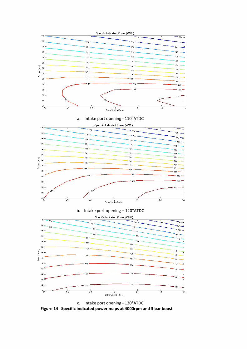
a. Intake port opening - 110°ATDC
b. Intake port opening – 120°ATDC
c. Intake port opening - 130°ATDC
Figure 14 Specific indicated power maps at 4000rpm and 3 bar boost

Figure 16 specific indicated power output at 4000rpm, 3 bar boost, and CA50 at 15 CA ATDC
(a) CA50 at 5°CA
(b) CA50 at 15°CA
Figure 15 In-Cylinder Peak Pressure
It can be seen from Fig.14 that the specific indicated power can reach 170kW/L. In the case of IPO at 110°ATDC, the best output performance was achieved with a higher bore/stroke ratio and shorter stroke. As the IPO was retarded to 120°ATDC, the high performance range was extended further, because of the increased effective expansion stroke. When the IPO timing was retarded further to 130°ATDC, the specific indicated power became lower because of the shorter intake port opening duration and hence reduced intake charge mass flow rate . Also, because of the higher boost pressure, the blow-down duration could be reduced from 60 to 40 CA.
Although the specific indicated power could reach a very high level, the corresponding in-cylinder peak pressure was also high. To reduce the peak pressure, the combustion phase was retarded by changing CA50 from 5°ATDC to 15°ATDC. IPO timing was kept at 120°ATDC and a blow-down duration 40°CA. As shown in Figure 15, the peak pressure was reduced by 25% with the retarded combustion phasing. But the specific indicated power still remained on a high level with the peak cylinder pressure kept below 120bar, as shown in Figure 16.
Effect of the Blow-down Duration
The intake port timing is determined by the intake port location in a 2-stroke uniflow engine. For a given intake port design, the intake port timing is fixed. The exhaust valves are driven by a camshaft and can be altered through a variable valve timing device. The optimised exhaust valve timing is a compromise of gas-exchanging performance and output power. With a longer blow-down duration, a higher trapping efficiency can be achieved, in another word, the “short-
circuiting” effect can be reduced. However, for a fixed IPO timing, longer blowdown duration means the exhaust valves need to be opened earlier. The power stroke will then be shortened and the output power will be reduced.
In order to investigate the effect of blow-down durations, a series of simulations under different engine operating speeds were carried out. The engine configuration was bore of 76mm, stroke of 67mm. IPO timing was set to 120°ATDC, and the boost pressure was set to 3bar absolute pressure.
Since the calculation of the brake engine output needs to take into account of frictional losses , the engine friction model in the 1-D engine simulation model was set up and calibrated. The engine friction data was obtained from Mahle I3 DI gasoline engine, which represents one of the most advanced boosted DI gasoline engine. The friction calculation based on Flynn-Chen model [10] is expressed as a quadratic equation,
𝐹𝑀𝐸𝑃 = 𝐴𝑐𝑓 + 1𝑛𝑐𝑦𝑙
∑ [𝐵𝑐𝑓�𝑃𝑐𝑦𝑙�𝑖 +𝑛𝑐𝑦𝑙𝑖=1
𝐶𝑐𝑓�𝑆𝑓𝑎𝑐𝑡�𝑖 + 𝑄𝑐𝑓�𝑆𝑓𝑎𝑐𝑡�𝑖2]
Where 𝑆𝑓𝑎𝑐𝑡 = 𝑅𝑃𝑀 ∗ 𝑠𝑡𝑟𝑜𝑘𝑒/2
𝑃𝑐𝑦𝑙 = 𝑝𝑒𝑎𝑘 𝑐𝑦𝑙𝑖𝑛𝑑𝑒𝑟 𝑝𝑟𝑒𝑠𝑠𝑢𝑟𝑒
Acf, Bcf, Ccf and Qcf were adjusted to replicate the FMEP values determined by engine experiments and then used to calculate FMEP at different load and speeds.
Figure 17 shows the effect of the blow-down duration on the brake specific power output at different engine speeds.

Figure 17 Effect of blowdown duration on specific brake power output with 3 bar boost
At low engine speeds, as the blowdown duration decreased, the brake specific power increased. However, for engine speeds above 3000rpm, the brake specific power increased first with shorter blowdown duration but started to decrease as the blowdown duration became very short (less than 50 CAs). Maximum power output was reached when a balance between the trapping efficiency and charge efficiency was reached. Therefore, it would be desirable that a variable valve timing device can be used to alter the exhaust valve timing for different engine operating conditions.
Boost system and multi-cylinder engine performance
3-cylinder 0.9 litre 2-stroke uniflow engine
A boost system is essential to the 2-stroke engine. This is because, unlike the 4-stroke cycle, the 2-stroke cycle requires boosted intake air to scavenge the in-cylinder residual gas out of the engine during the overlapped intake and exhaust periods as shown in Fig. 12.
Based on the 3-D CFD and 1-D engine performance simulation results discussed
previously, a 0.9 litre 3-cylinder uniflow 2-stroke engine configuration was chosen with a bore of 76mm and stroke of 67mm. IPO timing was set to 120°ATDC and the blow-down duration at 40 CA. Firstly, an engine model with a single-stage turbocharger was built up in the 1D calculation environment using Ricardo WAVE. The maps govern the turbine and compressor were created based on a production type turbocharger used for the Mahle I3 turbocharged DI gasoline engine. To suit the configured 2-stroke engine, the capacity of turbine and compressor were rescaled. The turbocharger supplies the engine a better overall efficiency, however, when the engine is running at low speed and low load, there is not sufficient exhaust energy to drive the turbine and the turbine operates near its surge limit. A supercharger is necessary to start the engine and provide the compressed air at low load operating conditions. The supercharger performance characteristics were based on Eaton’s supercharger R200GT or R410GT. Because the supercharger is driven by the crankshaft directly, the maximum intake boost pressure can be adjusted by optimising the gear ratio between crankshaft and supercharger shaft.

To investigate the engine performance, engine models with a supercharger or a turbocharger and both supercharge and turbocharger connected in series were set up respectively. The supercharger was located upstream of the turbocharger in the model with both supercharger and turbocharger.
Figure 18(a) shows the predicted brake power of the 3-cylinder 2-stroke uniflow engine with different boost methods against a modern 1.6L naturally aspirated 4-stroke PFI gasoline engine. With a supercharger, the engine performance was close to the 1.6L 4-stroke engine at medium and high speed. At low engine speed, the engine performance was lower than the corresponding 4-stroke engine. Furthermore, because of the engine speed was restricted to 4000rpm for the 2-stroke model, the maximum output power was only 56kW, 30% less than the corresponding 4-stroke engine. With the dual-boost system, the engine performance at low speed was improved and the maximum brake power of the 0.9 litre 2-stroke engine was 10% higher than the 1.6 litre 4-stroke engine. However, it is noted that the single turbocharger outperformed the dual-boost system. This was because the supercharger (R200GT) driven at a gear ratio of 6 reached its choked limit at high speeds and restricted the air flow into the engine.
(a) supercharger gear ratio 6
(b) supercharger gear ratio 10
Figure 18 Engine performance of models with various boost methods
When the supercharger’s gear ratio was increased to 10, the R200GT supercharged engine performance was improved at low and medium speed as shown in figure 18(b). However, the increased gear ratio had little effect on the performance of the engine with the duo-boost system due to the choked flow in the supercharger at medium and high engine speeds.
To achieve a higher level of output power, one option is the application of duo-boost system with a bigger supercharger.
Figure 19 shows the engine brake power and torque output with a larger supercharger R410GT. At the gear ratio 6, the maximum brake power reached 144kW, 82% higher than the 1.6L 4-stroke engine. When the gear ratio was set to 10, the engine power output could be increased further across the speed range but with a small drop at 4000 rpm. In particular, it is noted that the maximum torque can reach 344 Nm and 450 Nm by the duo-boost system of R410GT at gear ratio 6 and 10 respectively, three times of the base engine.
0
20
40
60
80
100
0 2000 4000 6000 8000
Brak
e Po
wer
[kW
]
Engine Speed [rpm]
1.6 NA PFI VW engine
2-stroke turbocharged engine
2-stroke superchargered engine
Duo-Boost
0102030405060708090
100
0 2000 4000 6000 8000
Brak
e Po
wer
[kW
]
Engine Speed [rpm] 1.6 NA PFI VW engine
2-stroke turbocharged engine
2-stroke superchargered engine
Duo-Boost
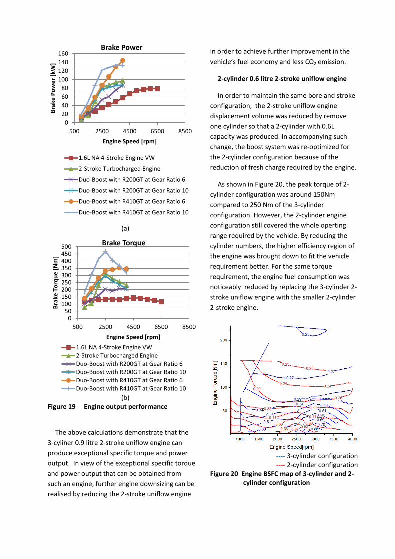
The above calculations demonstrate that the 3-cyliner 0.9 litre 2-stroke uniflow engine can produce exceptional specific torque and power output. In view of the exceptional specific torque and power output that can be obtained from such an engine, further engine downsizing can be realised by reducing the 2-stroke uniflow engine
in order to achieve further improvement in the vehicle’s fuel economy and less CO2 emission.
2-cylinder 0.6 litre 2-stroke uniflow engine
In order to maintain the same bore and stroke configuration, the 2-stroke uniflow engine displacement volume was reduced by remove one cylinder so that a 2-cylinder with 0.6L capacity was produced. In accompanying such change, the boost system was re-optimized for the 2-cylinder configuration because of the reduction of fresh charge required by the engine.
As shown in Figure 20, the peak torque of 2-cylinder configuration was around 150Nm compared to 250 Nm of the 3-cylinder configuration. However, the 2-cylinder engine configuration still covered the whole operting range required by the vehicle. By reducing the cylinder numbers, the higher efficiency region of the engine was brought down to fit the vehicle requirement better. For the same torque requirement, the engine fuel consumption was noticeably reduced by replacing the 3-cylinder 2-stroke uniflow engine with the smaller 2-cylinder 2-stroke engine.
---- 3-cylinder configuration ---- 2-cylinder configuration
Figure 20 Engine BSFC map of 3-cylinder and 2-cylinder configuration
(a)
(b)
Figure 19 Engine output performance
020406080
100120140160
500 2500 4500 6500 8500
Brak
e Po
wer
[kW
]
Engine Speed [rpm]
Brake Power
1.6L NA 4-Stroke Engine VW
2-Stroke Turbocharged Engine
Duo-Boost with R200GT at Gear Ratio 6
Duo-Boost with R200GT at Gear Ratio 10
Duo-Boost with R410GT at Gear Ratio 6
Duo-Boost with R410GT at Gear Ratio 10
050
100150200250300350400450500
500 2500 4500 6500 8500
Brak
e To
rque
[Nm
]
Engine Speed [rpm]
Brake Torque
1.6L NA 4-Stroke Engine VW2-Stroke Turbocharged EngineDuo-Boost with R200GT at Gear Ratio 6Duo-Boost with R200GT at Gear Ratio 10Duo-Boost with R410GT at Gear Ratio 6Duo-Boost with R410GT at Gear Ratio 10

One issue of boosted 2-stroke engine is the residual gas fraction at low load range. Because of poor delivery ratio and scavenging efficiency, the in-cylinder residual gas fraction can be very high.
Figure 21 In-cylinder residual gas fraction[%]
As shown in Figure 21, with typical exhaust valve timing (EVO@100°BTDC and EVC@250°BTDC), the in-cylinder residual gas fraction can go up to 80%. With high in-cylinder residual gas fraction, the conventional flame propagation cannot be obtained and partial-burning or misfire would occur as observed in conventional 2-stroke part-load operations. However, the recent research has demonstrated that CAI combustion could be readily obtained under part-load 2-stroke operations with better fuel economy than the 4-stroke SI engines [12].
---- Engine Torque ---- BSFC ---- In-Cylinder Residual Gas Fraction
Figure 22 in-cylinder residual gas fraction, BMEP and thermal efficiency against EVO(Exhaust Valve Opening) and EVC(Exhaust Valve Closing)
Alternatively, the in-cylinder residual gas fraction could be reduced through the variable exhaust valve timing. Figure 22 shows the in-cylinder residual gas fraction, engine torque and BSFC at 4000rpm engine speed and torque around 20Nm. With advanced EVO and retarded EVC, the engine torque and fuel consumption was maintained, whilst the in-cylinder residual gas fraction was reduced to less than 30%.
Conclusion
In this paper, results from a comprehensive study of the 2-stroke uniflow direct injection gasoline engine were presented and analysed. Effects of intake port design and engine geometry on the 2-stroke scavenging process and maximum engine performance were investigated by means of 3-D CFD and 1-D engine simulation. Boost configurations for maximum 2-stroke uniflow engine performance were studied. Finally, Optimised engine configuration for the most popular passenger car applications was
identified. Based on these studies, the following conclusions can be drawn:
1. There is an optimum intake port inclination angle for effective scavenging and better trapping efficienty. Larger intake port inclination angle causes greater air short circuiting and reduced scavenging performance due to clashes of incoming flow in the middle of cylinder. On the other hand, smaller intake port inclination angle causes the intake charge to flow towards the exhaust valves directly, resulting in poor scavenging and strong short circuiting.
2. When the intake port aspect ratio is fixed, a larger number of narrower ports produces stronger and more coherent in-cylinder swirl flow.
3. A larger intake port swirl orientation angle possesses better swirl generating ability but it requires narrower port and leads to a lower delivery ratio.
4. The 2-stroke uniflow direct injection gasoline engine can be designed to produce exceptional high specific torque and power output without producing excessive mechanical stress on the engine components.
5. It is necessary to use a combined supercharger and turbocharger system in order to obtain the maximum performance and better fuel economy across the engine operating range.
6. It is possible to replace a 4-cylinder 1.6 litre NA PFI gasoline engine with a 2-cylinder 0.6 litre 2-stroke uniflow DI gasoline engine with the potential for significant improvement in fuel economy and drivability.
Reference
1. Zhang, Y., Zhao, H., Ojapah, M., and Cairns, A., "2-Stroke CAI Operation on a
Poppet Valve DI Engine Fuelled with Gasoline and its Blends with Ethanol," SAE Technical Paper 2013-01-1674, 2013.
2. Daihasu press release, 1999 Frankfurt Motor show.
3. Reinhard, Knoll, ‘AVL Two-Stroke Diesel Engine’, SAE Paper 981038.
4. J. Abthoff, F. Duvinage, T. Hardt, M. Krämer and M. Paule, “The 2-Stroke DI-Diesel Engine with Common Rail Injection for Passenger Car Application”, SAE Paper 981032.
5. Yasuo Moriyoshi, Kazuhiro Kikuchi, Koji Morikawa, Hideharu Takimoto, ‘Numerical Analysis of Mixture Preparation in a Reverse Uniflow-Type Two-Stroke Gasoline DI Engine’, SAE Paper 2001-01-1815/4235.
6. Eduardo C. O. Pereira, Eurico F. A. Rodrigues, Jorge J. G. Martins, ‘Design of a Fuel Efficient Uniflow Two Stroke Semi-Direct Injection Engine’, SAE Paper 970367.
7. Gordon P. Blair, ‘Design and Simulation of Two-Stroke engines’.
8. John B. Heywood, ‘Internal Combustion Engine Fundamentals’
9. Kasser Jaffri, Hans G. Hascher, Mark Novak, Keunchul Lee, Harold Schock, Mike Bonne, Philip Keller, ‘Tumble and Swirl Quantification within a Motored Four-Valve SI Engine Cylinder Based on 3-D LDV Measurement’, SAE Paper 970792.
10. Chen, S. K. and P. F. Flynn. "Development of Single Cylinder Compression Ignition Research Engine", SAE Paper 650733, 1965 // WAVE Help System 8.3
Related Documents