Copyright Goodheart-Willcox Co., Inc. 44 CHAPTER 3 Number Systems and Codes Chapter Outline 3.1 Decimal Number System 3.2 Binary Number System 3.3 Binary-to-Decimal Conversion 3.4 Decimal-to-Binary Conversion 3.5 Binary Addition 3.6 Binary Subtraction 3.7 Binary Multiplication 3.8 Binary Division 3.9 Hexadecimal Number System 3.10 Octal Number System 3.11 Binary Coded Decimal System 3.12 Gray Code 3.13 Alphanumeric Code Technical Terms American Standard Code for Information Interchange (ASCII) base binary coded decimal (BCD) system binary number system borrow bit carry bit decimal number system dividend divisor Extended Binary Coded Decimal Interchange Code (EBCDIC) fractional numbers Gray code system hexadecimal number system (hex) integer numbers least significant bit (LSB) minuend most significant bit (MSB) multiplicand multiplier octal number system quotient real numbers subtrahend successive division method successive multiplication method photostock77/Shutterstock.com SAMPLE

Welcome message from author
This document is posted to help you gain knowledge. Please leave a comment to let me know what you think about it! Share it to your friends and learn new things together.
Transcript
Copyright Goodheart-Willcox Co., Inc.44
C H A P T E R 3
Number Systems and Codes
Chapter Outline3.1 Decimal Number System3.2 Binary Number System3.3 Binary-to-Decimal Conversion3.4 Decimal-to-Binary Conversion3.5 Binary Addition3.6 Binary Subtraction3.7 Binary Multiplication3.8 Binary Division3.9 Hexadecimal Number System3.10 Octal Number System3.11 Binary Coded Decimal System3.12 Gray Code3.13 Alphanumeric Code
Technical TermsAmerican Standard Code for
Information Interchange (ASCII)
basebinary coded decimal (BCD)
systembinary number systemborrow bitcarry bitdecimal number systemdividend
divisorExtended Binary Coded
Decimal Interchange Code (EBCDIC)
fractional numbersGray code systemhexadecimal number
system (hex)integer numbersleast significant bit (LSB)minuend
most significant bit (MSB)multiplicandmultiplieroctal number systemquotientreal numberssubtrahendsuccessive division methodsuccessive multiplication
method
photostock77/Shutterstock.com
SAMPLE
Copyright Goodheart-Willcox Co., Inc.
Chapter 3 Number Systems and Codes 45
Introduction
T he decimal number system, which has a base of ten (10), has been used as a number system since people started using numbers. This number system was invented because humans used their 10 fingers to keep track
of their counting.However, digital devices such as programmable logic controllers use a two-
state logic system in their central processing unit to count numbers and perform calculations. In two-state logic, the state is either high (e.g., +5 VDC) or low (e.g., 0 VDC). The high state is assigned to represent the number one (1) and the low state to represent the number zero (0). This type of number system is called the binary number system.
In this chapter, you will learn the binary number system and several other number systems that are used in digital devices. You will learn how to convert a number from one system to another. You will also learn how to perform math operations using the binary number system.
Learning ObjectivesAfter completing this chapter, you will be able to:
• Explain the decimal number system.• Explain integer numbers, fractional numbers, and real numbers.• Describe the binary number system.• Convert decimal numbers to binary and vice versa.• Perform binary math operations such as add, subtract, multiply, and divide.• Explain the hexadecimal number system.• Convert binary numbers to hexadecimal numbers and vice versa.• Explain the octal number system.• Convert binary numbers to octal numbers and vice versa.• Explain the binary coded decimal number system and its use.• Convert decimal numbers to binary coded decimals.• Explain the Gray code number system and its use.• Explain the ASCII and EBCDIC alphanumeric codes.
SAMPLE
Copyright Goodheart-Willcox Co., Inc.
46 Programmable Logic Controllers: Hardware and Programming
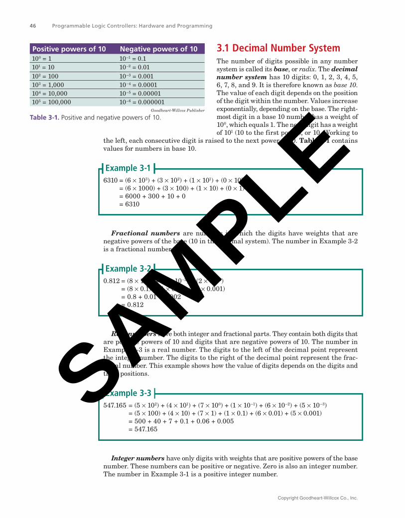
3.1 Decimal Number SystemThe number of digits possible in any number system is called its base, or radix. The decimal number system has 10 digits: 0, 1, 2, 3, 4, 5, 6, 7, 8, and 9. It is therefore known as base 10. The value of each digit depends on the position of the digit within the number. Values increase exponentially, depending on the base. The right-most digit in a base 10 number has a weight of 100, which equals 1. The next digit has a weight of 101 (10 to the first power), or 10. Working to
the left, each consecutive digit is raised to the next power of 10. Table 3‑1 contains values for numbers in base 10.
6310 = (6 × 10³) + (3 × 10²) + (1 × 101) + (0 × 100) = (6 × 1000) + (3 × 100) + (1 × 10) + (0 × 1) = 6000 + 300 + 10 + 0 = 6310
Example 3‑1
Fractional numbers are numbers in which the digits have weights that are negative powers of the base (10 in the decimal system). The number in Example 3-2 is a fractional number.
0.812 = (8 × 10⁻¹) + (1 × 10⁻²) + (2 × 10⁻³) = (8 × 0.1) + (1 × 0.01) + (2 × 0.001) = 0.8 + 0.01 + 0.002 = 0.812
Example 3‑2
Real numbers have both integer and fractional parts. They contain both digits that are positive powers of 10 and digits that are negative powers of 10. The number in Example 3-3 is a real number. The digits to the left of the decimal point represent the integer number. The digits to the right of the decimal point represent the frac-tional number. This example shows how the value of digits depends on the digits and their positions.
547.165 = (5 × 10²) + (4 × 101) + (7 × 100) + (1 × 10⁻¹) + (6 × 10⁻²) + (5 × 10⁻³) = (5 × 100) + (4 × 10) + (7 × 1) + (1 × 0.1) + (6 × 0.01) + (5 × 0.001) = 500 + 40 + 7 + 0.1 + 0.06 + 0.005 = 547.165
Example 3‑3
Integer numbers have only digits with weights that are positive powers of the base number. These numbers can be positive or negative. Zero is also an integer number. The number in Example 3-1 is a positive integer number.
Positive powers of 10 Negative powers of 10100 = 1 10–1 = 0.1101 = 10 10–2 = 0.01102 = 100 10–3 = 0.001103 = 1,000 10–4 = 0.0001104 = 10,000 10–5 = 0.00001105 = 100,000 10–6 = 0.000001
Goodheart-Willcox Publisher
Table 3‑1. Positive and negative powers of 10.
SAMPLE
Copyright Goodheart-Willcox Co., Inc.
Chapter 3 Number Systems and Codes 47
3.2 Binary Number SystemThe binary number system has a base of 2. It contains only two digits: 0 and 1. All binary numbers are created from combinations of these two digits.
There are three binary numbers in Example 3-4. The first two numbers are integer binary numbers and the last one is a real binary number. The rightmost digit of a binary number is called the least significant bit (LSB). Just as with the decimal system, the rightmost number has the smallest value. The leftmost digit of a binary number is called the most significant bit (MSB).
(11001)2 = (1 × 24) + (1 × 23) + (0 × 22) + (0 × 21) + (1 × 20) (11101)2 = (1 × 24) + (1 × 23) + (1 × 22) + (0 × 21) + (1 × 20) (111.0111)2 = (1 × 22) + (1 × 21) + (1 × 20) + (0 × 2–1) + (1 × 2–2) + (1 × 2–3) + (1 × 2–4)
Example 3‑4
Notice the subscript 2 following the numbers in Example 3-4. This notation is often used to indicate that it is a binary, or base 2, number. In the same way, a decimal number could be written (182)10 to show that it is a decimal, or base 10, number. However, since people normally work in the decimal number system, the base 10 is usually assumed and is not displayed with the number.
In the binary number system, a group of 4-bit binary digits is called nibble, and a group of 8-bit binary digits is called byte. Two bytes are referred to as a word, four bytes are a double word, and eight bytes are called a quad word. Therefore, 4-bit is called a nibble, 8-bit is called a byte, 16-bit is a word, 32-bit is a double word, and 64-bit is a quad word.
3.3 Binary‑to‑Decimal ConversionTo convert a number from binary to decimal, first convert each bit (digit) to its equiva-lent decimal value. Then, add all of these decimal values to obtain the decimal number. Example 3-5 illustrates how to convert integer and real binary numbers to decimal.
1. Convert the integer binary number 11101 to a decimal number. (11101)2 = (1 × 24) + (1 × 23) + (1 × 22) + (0 × 21) + (1 × 20) = 16 + 8 + 4 + 0 + 1 = (29)10 = 29
Now, work through some real binary numbers.2. Convert the real binary number 111.0111 to a decimal number.
(111.0111)2 = (1 × 22) + (1 × 21) + (1 × 20) + (0 × 2–1) + (1 × 2–2) + (1 × 2-3) + (1 × 2–4) = 4 + 2 + 1 + 0 + 0.25 + 0.125 + 0.0625 = 7.4375
3. Convert the real binary number 1001.1011 to a decimal number. 1001.1011 = (1 × 23) + (0 × 22) + (0 × 21) + (1 × 20) + (1 × 2–1) + (0 × 2–2) + (1 × 2–3)
+ (1 × 2–4) = 8 + 0 + 0 + 1 + 0.5 + 0 + 0.125 + 0.0625 = 9.6875
Example 3‑5
SAMPLE
Copyright Goodheart-Willcox Co., Inc.
48 Programmable Logic Controllers: Hardware and Programming
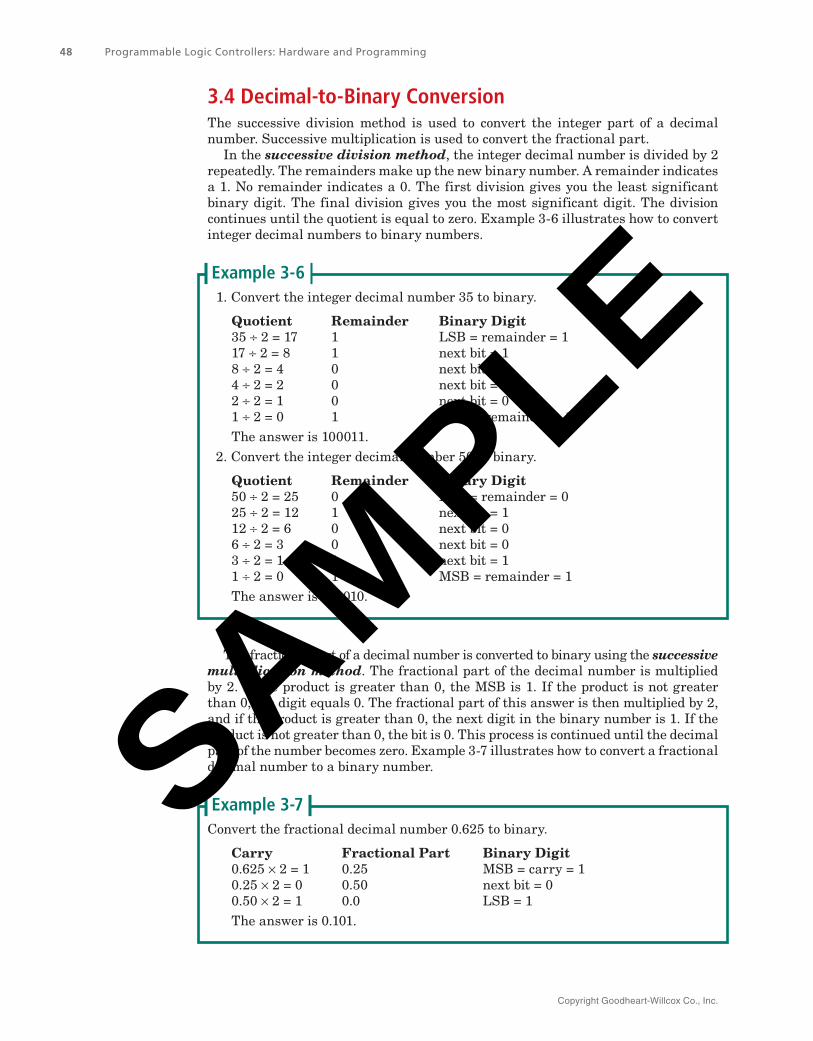
3.4 Decimal‑to‑Binary ConversionThe successive division method is used to convert the integer part of a decimal number. Successive multiplication is used to convert the fractional part.
In the successive division method, the integer decimal number is divided by 2 repeatedly. The remainders make up the new binary number. A remainder indicates a 1. No remainder indicates a 0. The first division gives you the least significant binary digit. The final division gives you the most significant digit. The division continues until the quotient is equal to zero. Example 3-6 illustrates how to convert integer decimal numbers to binary numbers.
1. Convert the integer decimal number 35 to binary.
Quotient Remainder Binary Digit35 ÷ 2 = 17 1 LSB = remainder = 117 ÷ 2 = 8 1 next bit = 18 ÷ 2 = 4 0 next bit = 04 ÷ 2 = 2 0 next bit = 02 ÷ 2 = 1 0 next bit = 01 ÷ 2 = 0 1 MSB = remainder = 1The answer is 100011.
2. Convert the integer decimal number 50 to binary.
Quotient Remainder Binary Digit50 ÷ 2 = 25 0 LSB = remainder = 025 ÷ 2 = 12 1 next bit = 112 ÷ 2 = 6 0 next bit = 06 ÷ 2 = 3 0 next bit = 03 ÷ 2 = 1 1 next bit = 11 ÷ 2 = 0 1 MSB = remainder = 1The answer is 110010.
Example 3‑6
The fractional part of a decimal number is converted to binary using the successive multiplication method. The fractional part of the decimal number is multiplied by 2. If the product is greater than 0, the MSB is 1. If the product is not greater than 0, the digit equals 0. The fractional part of this answer is then multiplied by 2, and if the product is greater than 0, the next digit in the binary number is 1. If the product is not greater than 0, the bit is 0. This process is continued until the decimal part of the number becomes zero. Example 3-7 illustrates how to convert a fractional decimal number to a binary number.
Convert the fractional decimal number 0.625 to binary.
Carry Fractional Part Binary Digit0.625 × 2 = 1 0.25 MSB = carry = 10.25 × 2 = 0 0.50 next bit = 00.50 × 2 = 1 0.0 LSB = 1The answer is 0.101.
Example 3‑7SAMPLE
Copyright Goodheart-Willcox Co., Inc.
Chapter 3 Number Systems and Codes 49
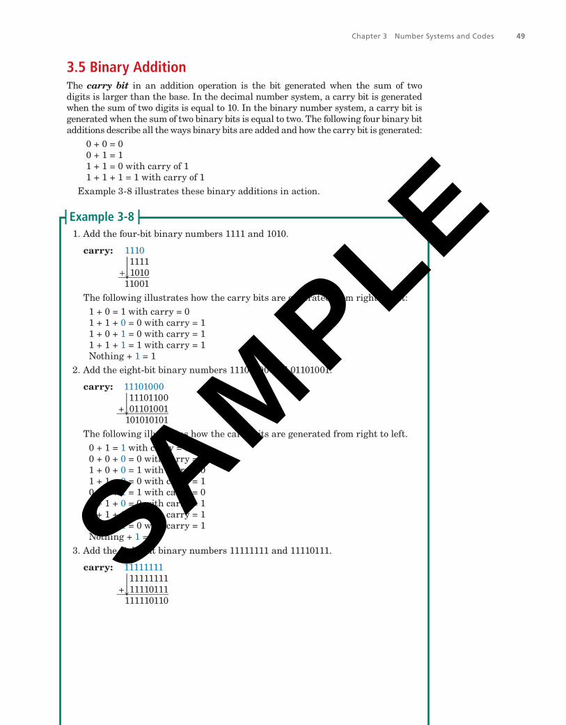
3.5 Binary AdditionThe carry bit in an addition operation is the bit generated when the sum of two digits is larger than the base. In the decimal number system, a carry bit is generated when the sum of two digits is equal to 10. In the binary number system, a carry bit is generated when the sum of two binary bits is equal to two. The following four binary bit additions describe all the ways binary bits are added and how the carry bit is generated:
0 + 0 = 00 + 1 = 11 + 1 = 0 with carry of 11 + 1 + 1 = 1 with carry of 1
Example 3-8 illustrates these binary additions in action.
1. Add the four-bit binary numbers 1111 and 1010.
carry: 1110 1111 + 1010
‾
11001The following illustrates how the carry bits are generated from right to left:
1 + 0 = 1 with carry = 01 + 1 + 0 = 0 with carry = 11 + 0 + 1 = 0 with carry = 11 + 1 + 1 = 1 with carry = 1Nothing + 1 = 1
2. Add the eight-bit binary numbers 11101100 and 01101001.
carry: 11101000 11101100 + 01101001
‾
101010101The following illustrates how the carry bits are generated from right to left.
0 + 1 = 1 with carry = 00 + 0 + 0 = 0 with carry = 01 + 0 + 0 = 1 with carry = 01 + 1 + 0 = 0 with carry = 10 + 0 + 1 = 1 with carry = 01 + 1 + 0 = 0 with carry = 11 + 1 + 1 = 1 with carry = 11 + 0 + 1 = 0 with carry = 1Nothing + 1 = 1
3. Add the eight-bit binary numbers 11111111 and 11110111.
carry: 11111111 11111111 + 11110111
‾
111110110
Example 3‑8
SAMPLE
Copyright Goodheart-Willcox Co., Inc.
50
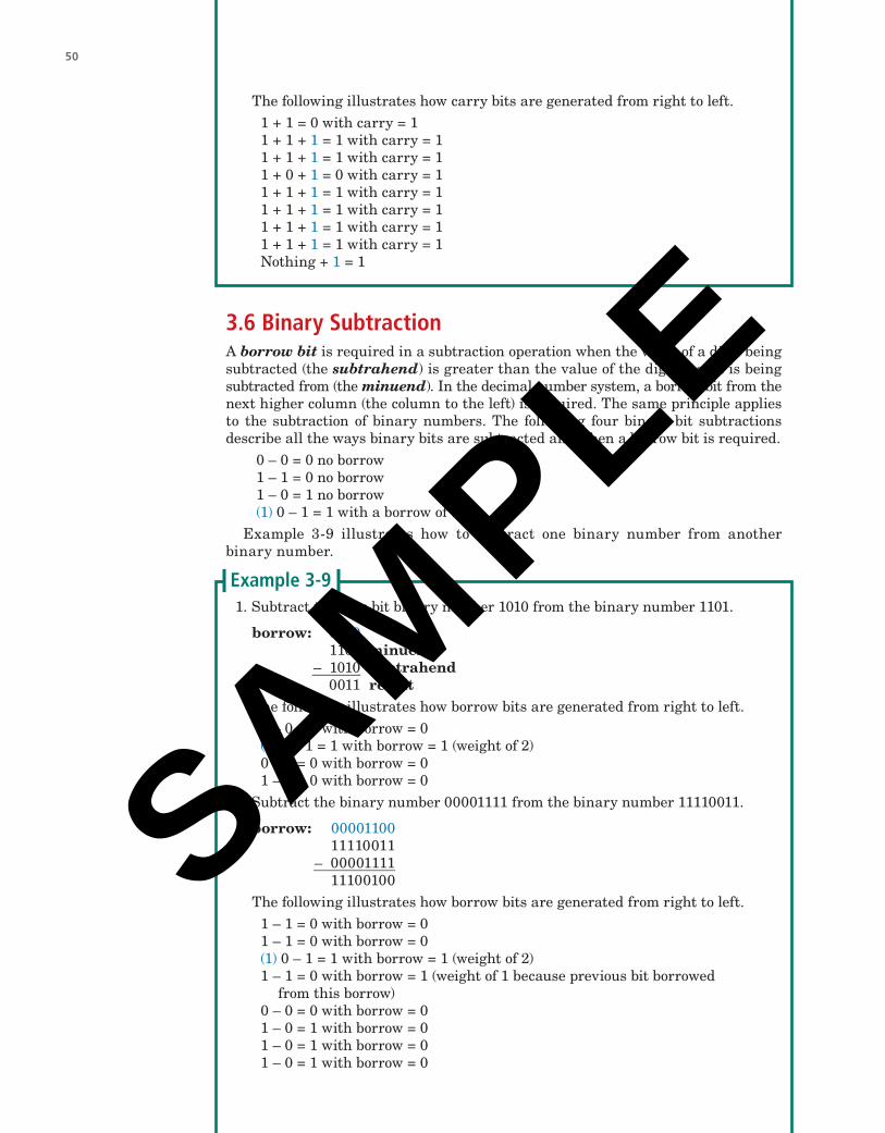
3.6 Binary SubtractionA borrow bit is required in a subtraction operation when the value of a digit being subtracted (the subtrahend) is greater than the value of the digit that it is being subtracted from (the minuend). In the decimal number system, a borrow bit from the next higher column (the column to the left) is required. The same principle applies to the subtraction of binary numbers. The following four binary bit subtractions describe all the ways binary bits are subtracted and when a borrow bit is required.
0 – 0 = 0 no borrow1 – 1 = 0 no borrow1 – 0 = 1 no borrow(1) 0 – 1 = 1 with a borrow of 1
Example 3-9 illustrates how to subtract one binary number from another binary number.
1. Subtract the four-bit binary number 1010 from the binary number 1101.
borrow: 0010 1101 minuend – 1010
‾ subtrahend
0011 resultThe following illustrates how borrow bits are generated from right to left.
1 – 0 = 1 with borrow = 0(1) 0 – 1 = 1 with borrow = 1 (weight of 2)0 – 0 = 0 with borrow = 01 – 1 = 0 with borrow = 0
2. Subtract the binary number 00001111 from the binary number 11110011.
borrow: 00001100 11110011 – 00001111
‾
11100100The following illustrates how borrow bits are generated from right to left.
1 – 1 = 0 with borrow = 01 – 1 = 0 with borrow = 0(1) 0 – 1 = 1 with borrow = 1 (weight of 2)1 – 1 = 0 with borrow = 1 (weight of 1 because previous bit borrowed
from this borrow)0 – 0 = 0 with borrow = 01 – 0 = 1 with borrow = 01 – 0 = 1 with borrow = 01 – 0 = 1 with borrow = 0
Example 3‑9
The following illustrates how carry bits are generated from right to left.1 + 1 = 0 with carry = 11 + 1 + 1 = 1 with carry = 11 + 1 + 1 = 1 with carry = 11 + 0 + 1 = 0 with carry = 11 + 1 + 1 = 1 with carry = 11 + 1 + 1 = 1 with carry = 11 + 1 + 1 = 1 with carry = 11 + 1 + 1 = 1 with carry = 1Nothing + 1 = 1
SAMPLE
Copyright Goodheart-Willcox Co., Inc.
51
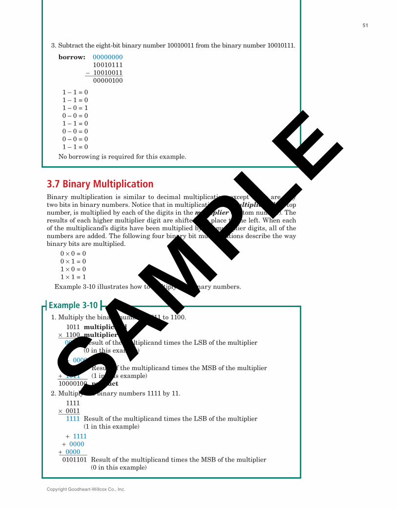
3.7 Binary MultiplicationBinary multiplication is similar to decimal multiplication, except there are only two bits in binary numbers. Notice that in multiplication, the multiplicand, or top number, is multiplied by each of the digits in the multiplier (bottom number). The results of each higher multiplier digit are shifted one place to the left. When each of the multiplicand’s digits have been multiplied by the multiplier digits, all of the numbers are added. The following four binary bit multiplications describe the way binary bits are multiplied.
0 × 0 = 00 × 1 = 01 × 0 = 01 × 1 = 1
Example 3-10 illustrates how to multiply two binary numbers.
1. Multiply the binary numbers 1011 to 1100. 1011 multiplicand × 1100
‾ multiplier
0000 Result of the multiplicand times the LSB of the multiplier (0 in this example) + 0000 + 1011 Result of the multiplicand times the MSB of the multiplier + 1011
‾ (1 in this example)
10000100 product2. Multiply the binary numbers 1111 by 11.
1111 × 0011
‾
1111 Result of the multiplicand times the LSB of the multiplier (1 in this example) + 1111 + 0000 + 0000
‾
0101101 Result of the multiplicand times the MSB of the multiplier (0 in this example)
Example 3‑10
3. Subtract the eight-bit binary number 10010011 from the binary number 10010111.
borrow: 00000000 10010111 – 10010011
‾
00000100
1 – 1 = 0 1 – 1 = 0 1 – 0 = 1 0 – 0 = 0 1 – 1 = 0 0 – 0 = 0 0 – 0 = 0 1 – 1 = 0
No borrowing is required for this example.
SAMPLE
Copyright Goodheart-Willcox Co., Inc.
52 Programmable Logic Controllers: Hardware and Programming
3.8 Binary DivisionDivision can be explained as how many times a number called the divisor can be subtracted from the dividend (the number being divided). The subtraction routine continues until the remainder is less than the dividend. The number of times the divisor can be subtracted from the dividend is called the quotient. Example 3-11 illustrates how to divide a binary number by another binary number using the repeated subtraction method.
Divide the binary number 11000 by 110 using the repeated subtraction method. 11000 dividend – 110
‾ divisor
10010Next, 10010
– 110 ‾
01100
Next, 01100 – 110
‾
00110Next, 00110
– 110 ‾
000 Remainder is less than divisor; therefore, stop.
Four subtractions took place; therefore, the quotient is equal to 1002 (binary), which is equal to decimal 4 (1002 = 410).
Example 3‑11
3.9 Hexadecimal Number SystemIn medium to larger programmable logic controllers (PLCs), the hexadecimal number system, often just called hex, is used to display the PLC memory map and to carry out the math instructions. The hexadecimal number system has a base of 16.
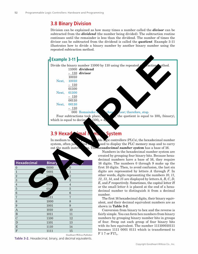
Numbers in the hexadecimal number system are created by grouping four binary bits. Because hexa-decimal numbers have a base of 16, they require 16 digits. The numbers 0 through 9 make up the first 10 digits. Then, to avoid confusion, the last six digits are represented by letters A through F. In other words, digits representing the numbers 10, 11, 12, 13, 14, and 15 are displayed by letters A, B, C, D, E, and F respectively. Sometimes, the capital letter H or the small letter h is placed at the end of a hexa-decimal number to distinguish it from a decimal number.
The first 16 hexadecimal digits, their binary equiv-alent, and their decimal equivalent numbers are as shown in Table 3‑2.
Conversion from binary to hex and the reverse is fairly simple. You can form hex numbers from binary numbers by grouping binary number bits in groups of four. Swap out each group of four binary bits with its hex equivalent. The number 111100010111 becomes 1111 0001 0111 which is transformed to F 1 7 or F17h.
Hexadecimal Binary Decimal0 0000 01 0001 12 0010 23 0011 34 0100 45 0101 56 0110 67 0111 78 1000 89 1001 9A 1010 10B 1011 11C 1100 12D 1101 13E 1110 14F 1111 15
Goodheart-Willcox Publisher
Table 3‑2. Hexadecimal, binary, and decimal equivalents.
SAMPLE
Copyright Goodheart-Willcox Co., Inc.
Chapter 3 Number Systems and Codes 53
Reverse the process to convert to binary. Take each hex digit and swap it with the binary 4-bit equivalent. The number 37Ah becomes 0011 0111 1010 or 001101111010.
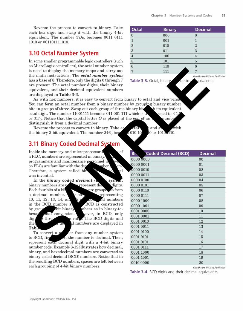
3.10 Octal Number SystemIn some smaller programmable logic controllers (such as MicroLogix controllers), the octal number system is used to display the memory maps and carry out the math instructions. The octal number system has a base of 8. Therefore, only the digits 0 through 7 are present. The octal number digits, their binary equivalent, and their decimal equivalent numbers are displayed in Table 3‑3.
As with hex numbers, it is easy to convert from binary to octal and vice versa. You can form an octal number from a binary number by grouping binary number bits in groups of three. Swap out each group of three binary bits with its equivalent octal digit. The number 11001111 becomes 011 001 111 which is transformed to 3 1 7 or 317O. Notice that the capital letter O is placed at the end of an octal number to distinguish it from a decimal number.
Reverse the process to convert to binary. Take each octal digit and swap it with the binary 3-bit equivalent. The number 246O becomes 010 100 110 or 10100110.
3.11 Binary Coded Decimal SystemInside the memory and microprocessor registers of a PLC, numbers are represented in binary. However, programmers and maintenance personnel who work on PLCs are familiar with the decimal number system. Therefore, a system called binary coded decimal was invented.
In the binary coded decimal (BCD) system, binary numbers are used to represent decimal digits. Each four bits of a binary number are grouped to form a decimal number. Four-bit groups representing 10, 11, 12, 13, 14, and 15 are not valid numbers in the BCD number system. BCD is constructed by grouping 4-bit binary numbers as in binary-to-hexadecimal conversion. However, in BCD, only digits 0 through 9 are valid. The BCD digits and their equivalent decimal numbers are displayed in Table 3‑4.
To convert a number from any number system to BCD, first convert the number to decimal. Then, represent each decimal digit with a 4-bit binary number code. Example 3-12 illustrates how decimal, binary, and hexadecimal numbers are converted to binary coded decimal (BCD) numbers. Notice that in the resulting BCD numbers, spaces are left between each grouping of 4-bit binary numbers.
Octal Binary Decimal0 000 01 001 12 010 23 011 34 100 45 101 56 110 67 111 7
Goodheart-Willcox Publisher
Table 3‑3. Octal, binary, and decimal equivalents.
Binary Coded Decimal (BCD) Decimal0000 0000 000000 0001 010000 0010 020000 0011 030000 0100 040000 0101 050000 0110 060000 0111 070000 1000 080000 1001 090001 0000 100001 0001 110001 0010 120001 0011 130001 0100 140001 0101 150001 0101 160001 0111 170001 1000 180001 1001 190010 0000 20
Goodheart-Willcox Publisher
Table 3‑4. BCD digits and their decimal equivalents.
SAMPLE
Copyright Goodheart-Willcox Co., Inc.
54 Programmable Logic Controllers: Hardware and Programming
1. Convert the decimal number 273.125 to BCD. Simply convert each digit into its binary equivalent, keeping the decimal point
at the same relative location (between BCD equivalents for the 3 and the 1).2 7 3 1 2 50010 0111 0011 0001 0010 0101
Therefore, 273.125 = 0010 0111 0011. 0001 0010 0101BCD
2. Convert binary number 1101.10 to BCD. First, convert to decimal.
1101.10 = (1 × 23) + (1 × 22) + (0 × 21) + (1 × 20) + (1 × 2–1) + (0 × 2–2) = 8 + 4 + 0 + 1 + 0.5 + 0 = 13.5 decimal Then, convert to BCD.
13.5 = 0001 0011. 0101 Therefore, 1101.102 = 0001 0011. 0101BCD
3. Convert hex number 1ABH to BCD. To convert hex to BCD, first convert the hex number into decimal.
1ABH = (1 × 162) + (10 × 161) + (11 × 160) = 427 decimal Next, convert each decimal digit into its binary equivalent.
4 2 70100 0010 0111 = 0100 0010 0111BCD
Example 3‑12
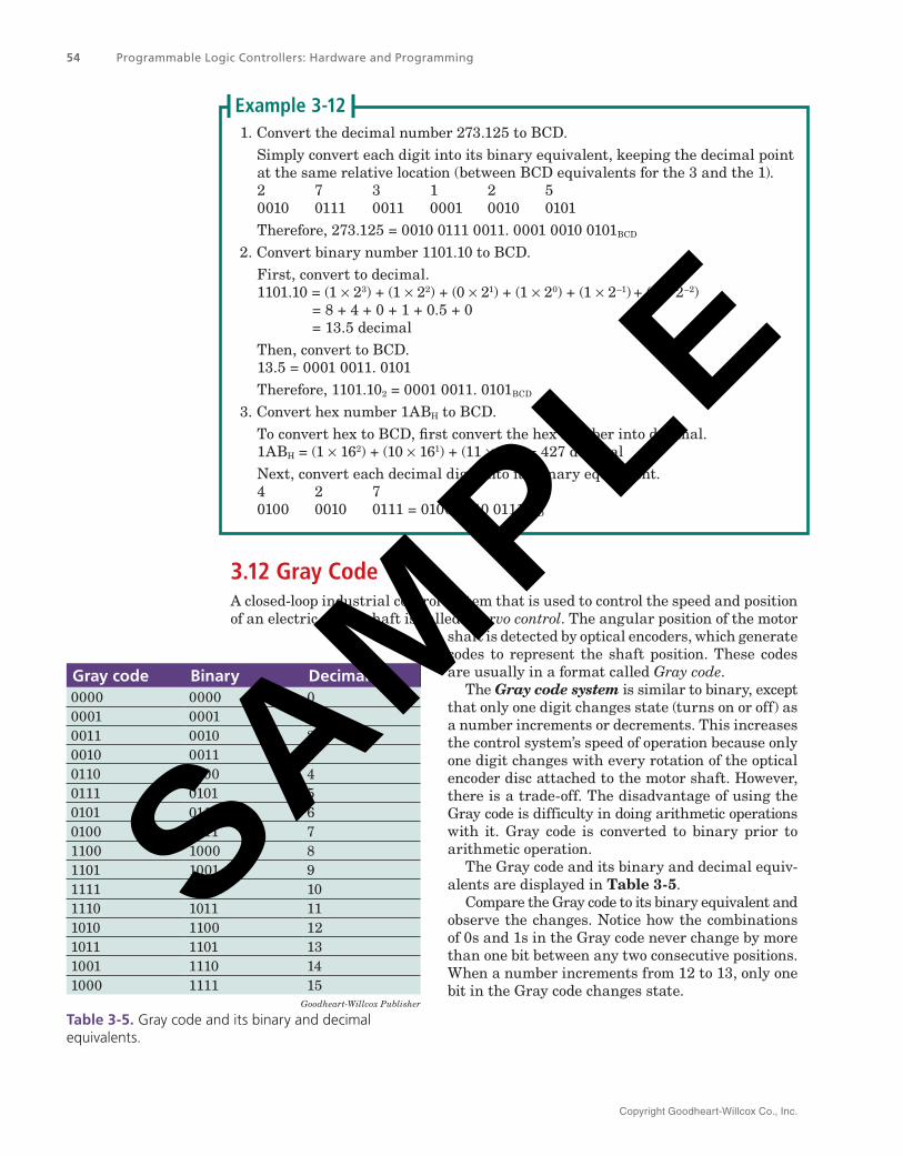
3.12 Gray CodeA closed-loop industrial control system that is used to control the speed and position of an electric motor shaft is called a servo control. The angular position of the motor
shaft is detected by optical encoders, which generate codes to represent the shaft position. These codes are usually in a format called Gray code.
The Gray code system is similar to binary, except that only one digit changes state (turns on or off) as a number increments or decrements. This increases the control system’s speed of operation because only one digit changes with every rotation of the optical encoder disc attached to the motor shaft. However, there is a trade-off. The disadvantage of using the Gray code is difficulty in doing arithmetic operations with it. Gray code is converted to binary prior to arithmetic operation.
The Gray code and its binary and decimal equiv-alents are displayed in Table 3‑5.
Compare the Gray code to its binary equivalent and observe the changes. Notice how the combinations of 0s and 1s in the Gray code never change by more than one bit between any two consecutive positions. When a number increments from 12 to 13, only one bit in the Gray code changes state.
Gray code Binary Decimal0000 0000 00001 0001 10011 0010 20010 0011 30110 0100 40111 0101 50101 0110 60100 0111 71100 1000 81101 1001 91111 1010 101110 1011 111010 1100 121011 1101 131001 1110 141000 1111 15
Goodheart-Willcox Publisher
Table 3‑5. Gray code and its binary and decimal equivalents.
SAMPLE
Copyright Goodheart-Willcox Co., Inc.
Chapter 3 Number Systems and Codes 55
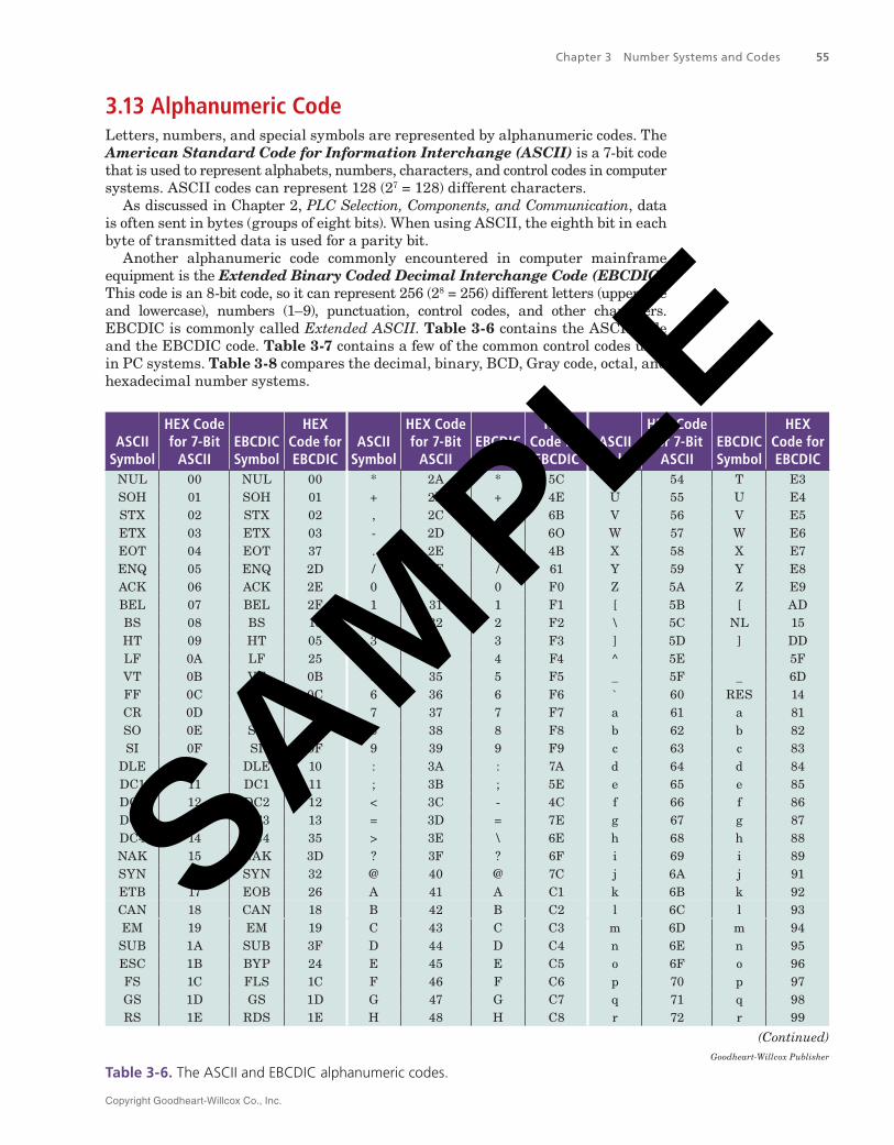
3.13 Alphanumeric CodeLetters, numbers, and special symbols are represented by alphanumeric codes. The American Standard Code for Information Interchange (ASCII) is a 7-bit code that is used to represent alphabets, numbers, characters, and control codes in computer systems. ASCII codes can represent 128 (27 = 128) different characters.
As discussed in Chapter 2, PLC Selection, Components, and Communication, data is often sent in bytes (groups of eight bits). When using ASCII, the eighth bit in each byte of transmitted data is used for a parity bit.
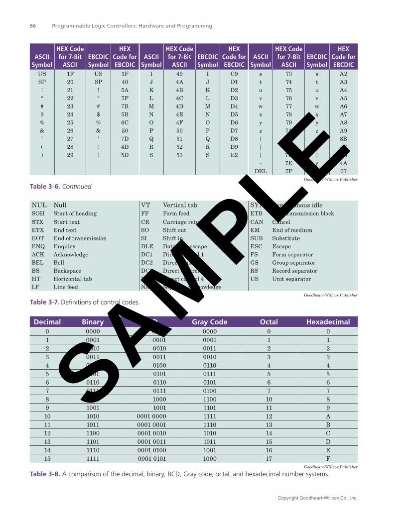
Another alphanumeric code commonly encountered in computer mainframe equipment is the Extended Binary Coded Decimal Interchange Code (EBCDIC). This code is an 8-bit code, so it can represent 256 (28 = 256) different letters (uppercase and lowercase), numbers (1–9), punctuation, control codes, and other characters. EBCDIC is commonly called Extended ASCII. Table 3‑6 contains the ASCII code and the EBCDIC code. Table 3‑7 contains a few of the common control codes used in PC systems. Table 3‑8 compares the decimal, binary, BCD, Gray code, octal, and hexadecimal number systems.
ASCII Symbol
HEX Code for 7‑Bit
ASCII EBCDIC Symbol
HEX Code for EBCDIC
ASCII Symbol
HEX Code for 7‑Bit
ASCIIEBCDIC Symbol
HEX Code for EBCDIC
ASCII Symbol
HEX Code for 7‑Bit
ASCIIEBCDIC Symbol
HEX Code for EBCDIC
NUL 00 NUL 00 * 2A * 5C T 54 T E3SOH 01 SOH 01 + 2B + 4E U 55 U E4STX 02 STX 02 , 2C , 6B V 56 V E5ETX 03 ETX 03 - 2D - 6O W 57 W E6EOT 04 EOT 37 . 2E . 4B X 58 X E7ENQ 05 ENQ 2D / 2F / 61 Y 59 Y E8ACK 06 ACK 2E 0 30 0 F0 Z 5A Z E9BEL 07 BEL 2F 1 31 1 F1 [ 5B [ ADBS 08 BS 16 2 32 2 F2 \ 5C NL 15HT 09 HT 05 3 33 3 F3 ] 5D ] DDLF 0A LF 25 4 34 4 F4 ^ 5E 5FVT 0B VT 0B 5 35 5 F5 _ 5F _ 6DFF 0C FF 0C 6 36 6 F6 ` 60 RES 14CR 0D CR 0D 7 37 7 F7 a 61 a 81SO 0E SO 0E 8 38 8 F8 b 62 b 82SI 0F SI 0F 9 39 9 F9 c 63 c 83
DLE 10 DLE 10 : 3A : 7A d 64 d 84DC1 11 DC1 11 ; 3B ; 5E e 65 e 85DC2 12 DC2 12 < 3C - 4C f 66 f 86DC3 13 DC3 13 = 3D = 7E g 67 g 87DC4 14 DC4 35 > 3E \ 6E h 68 h 88NAK 15 NAK 3D ? 3F ? 6F i 69 i 89SYN 16 SYN 32 @ 40 @ 7C j 6A j 91ETB 17 EOB 26 A 41 A C1 k 6B k 92CAN 18 CAN 18 B 42 B C2 l 6C l 93EM 19 EM 19 C 43 C C3 m 6D m 94SUB 1A SUB 3F D 44 D C4 n 6E n 95ESC 1B BYP 24 E 45 E C5 o 6F o 96FS 1C FLS 1C F 46 F C6 p 70 p 97GS 1D GS 1D G 47 G C7 q 71 q 98RS 1E RDS 1E H 48 H C8 r 72 r 99
(Continued)Goodheart-Willcox Publisher
Table 3‑6. The ASCII and EBCDIC alphanumeric codes.
SAMPLE
Copyright Goodheart-Willcox Co., Inc.
56 Programmable Logic Controllers: Hardware and Programming
ASCII Symbol
HEX Code for 7‑Bit
ASCII EBCDIC Symbol
HEX Code for EBCDIC
ASCII Symbol
HEX Code for 7‑Bit
ASCIIEBCDIC Symbol
HEX Code for EBCDIC
ASCII Symbol
HEX Code for 7‑Bit
ASCIIEBCDIC Symbol
HEX Code for EBCDIC
US 1F US 1F I 49 I C9 s 73 s A2SP 20 SP 40 J 4A J D1 t 74 t A3! 21 ! 5A K 4B K D2 u 75 u A4“ 22 “ 7F L 4C L D3 v 76 v A5# 23 # 7B M 4D M D4 w 77 w A6$ 24 $ 5B N 4E N D5 x 78 x A7% 25 % 6C O 4F O D6 y 79 y A8& 26 & 50 P 50 P D7 z 7A z A9‘ 27 ‘ 7D Q 51 Q D8 { 7B { 8B( 28 ( 4D R 52 R D9 | 7C | 4F) 29 ) 5D S 53 S E2 } 7D } 9B
- 7E ¢ 4ADEL 7F DEL 07
Goodheart-Willcox Publisher
Table 3‑6. Continued
NUL Null VT Vertical tab SYN Synchronous idleSOH Start of heading FF Form feed ETB End transmission block
STX Start text CR Carriage return CAN CancelETX End text SO Shift out EM End of mediumEOT End of transmission SI Shift in SUB SubstituteENQ Enquiry DLE Data link escape ESC EscapeACK Acknowledge DC1 Direct control 1 FS Form separatorBEL Bell DC2 Direct control 2 GS Group separatorBS Backspace DC3 Direct control 3 RS Record separatorHT Horizontal tab DC4 Direct control 4 US Unit separatorLF Line feed NAK Negative acknowledge
Goodheart-Willcox Publisher
Table 3‑7. Definitions of control codes.
Decimal Binary BCD Gray Code Octal Hexadecimal0 0000 0000 0000 0 01 0001 0001 0001 1 12 0010 0010 0011 2 23 0011 0011 0010 3 34 0100 0100 0110 4 45 0101 0101 0111 5 56 0110 0110 0101 6 67 0111 0111 0100 7 78 1000 1000 1100 10 89 1001 1001 1101 11 910 1010 0001 0000 1111 12 A11 1011 0001 0001 1110 13 B12 1100 0001 0010 1010 14 C13 1101 0001 0011 1011 15 D14 1110 0001 0100 1001 16 E15 1111 0001 0101 1000 17 F
Goodheart-Willcox Publisher
Table 3‑8. A comparison of the decimal, binary, BCD, Gray code, octal, and hexadecimal number systems.
SAMPLE
Copyright Goodheart-Willcox Co., Inc.
Chapter 3 Number Systems and Codes 57
Summary• The number systems commonly used with PLCs
are the decimal number system, binary number system, hexadecimal number system, octal number system, binary coded decimal system, Gray code system, and alphanumeric codes.
• The decimal number system has 10 digits running from 0 through 9.
• The value for each digit in a decimal number system depends on the position of the digit within the number.
• The binary number system consists of only the digits 0 and 1.
• To convert binary to decimal, you must first convert each bit to its equivalent decimal value and then add all of these decimal values.
• To convert decimal to binary, the successive division method is used to convert the integer part of a decimal number, and the successive multiplication method is used to convert the fractional part.
• In the binary number system, a carry bit is generated when the sum of two binary bits is equal to two.
• In binary multiplication, when each of the multiplicand’s digits have been multiplied by the multiplier digits, all of the numbers are added.
• In binary division, the divisor is subtracted from the dividend repeatedly until the remainder is less than the dividend.
• The hexadecimal number system is used to display the PLC memory map and to carry out the math instructions and is created by grouping four binary bits. Hexadecimal numbers have a base of 16 and require 16 digits. This system uses the numbers 0 through 9 for the first 10 digits and the letters A through F for the last six digits (10 through 15).
• The octal number system is used to display the memory maps and carry out the math instructions in smaller PLCs. The octal number system has a base of eight and only the digits 0 through 7 are present.
• BCD is constructed by grouping 4-bit binary numbers; however, in BCD, only the digits 0 through 9 are valid.
• In the Gray code system, only one digit changes state (turns on or off) as a number increments or decrements.
• Letters, numbers, and special symbols are represented by alphanumeric codes. The American Standard Code for Information Interchange (ASCII) is a 7-bit code used to represent alphabets, numbers, characters, and control codes in computer systems.
• The Extended Binary Coded Decimal Interchange Code (EBCDIC) is an 8-bit code that represents 256 different characters, including alphabets (uppercase and lowercase), numbers (1–9), punctuation, control codes, and other characters.
Know and Understand1. In decimal number 923.167, the weight of 2
is _____.A. 10B. 10–1
C. 102
D. 10–2
2. The highest decimal number that can be presented by a nibble in the binary system is _____.
A. 9B. 15C. 32D. 8
3. In binary addition, 1+1+1 is equal to _____.A. 1 with a carry of 0B. 1 with no carryC. 0 with a carry of 1D. 1 with a carry of 1
4. In a number system, the word “radix” means _____.
A. HEXB. BYTEC. BCDD. BASE
SAMPLE
Copyright Goodheart-Willcox Co., Inc.
58 Programmable Logic Controllers: Hardware and Programming
5. Real numbers have _____.A. only an integer partB. only a fractional partC. both integer and fractional partsD. None of the above.
6. In the Gray code system, _____.A. only one bit can turn on when the
number changesB. only one bit can turn off when the
number changesC. only one bit can change status when the
number changesD. All of the above.
7. One’s complement of binary number 11011100 is _____.
A. 01011100B. 00100011C. 10100011D. 11011101
8. In an 8-bit negative binary number, _____.A. the least significant bit (LSB) is oneB. the least significant bit (LSB) is zeroC. the most significant bit (MSB) is oneD. the most significant bit (MSB) is zero
9. Which one of the following statements is false?A. Each BCD digit is represented by a nibble.B. Each HEX digit is represented by a nibble.C. The BCD number system is more efficient
than HEX for representing numbers in computer memory.
D. The HEX number system is more efficient than BCD for representing numbers in computer memory.
10. Which one of the following statements is false?A. ASCII code can represent 128 characters.B. EBCDIC code (sometimes called extended
ASCII code) can represent 256 characters.C. Gray code is used to present the angular
position of a motor shaft.D. None of the above.
11. In the HEX number A8D, the weight of 8 is _____.A. 16B. 162
C. 163
D. 102
12. Convert the binary number 11011100 1000 1010 to HEX.
A. DB8AB. DC8AC. EB8AD. EC8A
13. Which one of the following numbers is an incorrect binary coded decimal number?
A. 0101B. 1001C. 1010D. 0111
14. Select the 621 odd-parity BCD number transmitted in the serial communication system:
A. 00110 0010 0001B. 10110 0010 0001C. 10111 0010 0001D. 10110 0011 0001
15. A number with an exponent of zero is _____.A. zeroB. tenC. itselfD. one
16. 0000 1010 as a decimal number would be _____.A. 0.50B. 0.25C. 0.125D. 0.625
17. 15.65 as a binary number would be _____.A. 1101 1001B. 1101 1010C. 1111 1001D. 1111 1010
18. How many different digits are used in an octal number system?
A. SevenB. EightC. NineD. TenSAMPLE
Copyright Goodheart-Willcox Co., Inc.
Chapter 3 Number Systems and Codes 59
Apply and Analyze1. Find the maximum decimal values for the
following groups of binary bit (the value if all bits in the group are 1).
A. 4-bit (called a nibble)B. 8-bit (called a byte)C. 16-bit (called a word)D. 32-bit (called a double word)E. 64-bit (called a quad word)
2. Convert hexadecimal number AB12h to its decimal equivalent.
3. Convert hexadecimal number 15CD.A2h to its binary equivalent.
4. Convert binary number 110111.00111 to its hexadecimal equivalent.
5. Convert the following decimal numbers to octal numbers.
A. 25B. 127C. 365
6. Convert the following binary numbers to octal numbers.
A. 110111B. 1111000111.01C. 1000111001.1D. 1110011100.0110
7. Convert the following binary numbers to BCD numbers.
A. 111B. 1110C. 10000D. 100010E. 100110
8. Write your first name in the ASCII code.9. Write your last name in the EBCDIC code.
10. Convert the following BCD numbers to decimal.A. 0010 0010BCD
B. 0100 1000BCD
C. 0101 0111BCD
D. 1001 1000BCD
Critical Thinking1. Add the following binary numbers.
A. 1100 + 1111B. 11000111 + 11000000C. 10101011 + 11110011
2. Perform the following binary subtractions.A. A100 – 1001B. 10001100 – 10000101
3. Multiply the following binary numbers.A. 10101 × 1011B. 11011100 × 10101111
4. Solve the following division problems.A. 11000111 ÷ 1010B. 10101111 ÷ 1111
SAMPLE
Related Documents


