sustainable development commission The role of nuclear power in a low carbon economy Paper 1: An introduction to nuclear power – science, technology and UK policy context An evidence-based report by the Sustainable Development Commission March 2006

Welcome message from author
This document is posted to help you gain knowledge. Please leave a comment to let me know what you think about it! Share it to your friends and learn new things together.
Transcript

sustainable development commission
The role of nuclear power in a low carbon economy
Paper 1: An introduction to
nuclear power – science, technology and
UK policy context
An evidence-based report by the Sustainable Development Commission
March 2006


Table of contents 1 INTRODUCTION ................................................................................................................................. 3 2 ELECTRICITY GENERATION ................................................................................................................. 4
2.1 Nuclear electricity generation ................................................................................................. 4 2.2 Fission – how does it work?..................................................................................................... 4 2.3 Moderator ................................................................................................................................. 5 2.4 Coolant ...................................................................................................................................... 5 2.5 Radioactivity ............................................................................................................................. 6
3 THE FUEL CYCLE: FRONT END ............................................................................................................ 7 3.1 Mining and milling ................................................................................................................... 7 3.2 Conversion and enrichment..................................................................................................... 7 3.3 Fabrication ................................................................................................................................ 8 3.4 Plant operations ....................................................................................................................... 8
4 THE FUEL CYCLE: BACK END ............................................................................................................ 10 4.1 Reprocessing .......................................................................................................................... 10
4.1.1 MOX fuel .......................................................................................................................... 10 4.2 Waste storage and disposal................................................................................................... 10
4.2.1 Low-level wastes (LLW).................................................................................................. 11 4.2.2 Intermediate-level wastes (ILW) ................................................................................... 11 4.2.3 High-level wastes (HLW) ................................................................................................ 11 4.2.4 Other radioactive materials ............................................................................................ 12
4.3 Decommissioning ................................................................................................................... 12 5 NUCLEAR TECHNOLOGIES ................................................................................................................ 14
5.1 Past technologies - generations I & II .................................................................................. 14 5.1.1 Magnox ........................................................................................................................... 14 5.1.2 Advanced gas-cooled reactor (AGR) .............................................................................. 14 5.1.3 Pressurised water reactor (PWR) ................................................................................... 15
5.2 Near term technologies – generations III & III+.................................................................... 15 5.2.1 Advanced CANDU reactor (ACR-700 & ACR-1000) ........................................................ 16 5.2.2 Advanced passive series (AP600 & AP1000) ............................................................... 16 5.2.3 European pressurised water reactor (EPR) .................................................................... 17
5.3 Other generation III designs ................................................................................................. 17 5.3.1 The advanced boiling water reactor (ABWR) ................................................................ 17 5.3.2 The economic & simplified BWR (ESBWR) ..................................................................... 18 5.3.3 Other designs .................................................................................................................. 18 5.3.4 The international reactor innovative & secure (IRIS) .................................................... 19 5.3.5 The pebble bed modular reactor (PBMR) ...................................................................... 19
5.4 Generation IV ......................................................................................................................... 19 5.4.1 Gas-cooled fast reactors (GFR) ....................................................................................... 20 5.4.2 Sodium-cooled fast reactors (SFR) ................................................................................. 20 5.4.3 Very high temperature gas reactors (VHTR).................................................................. 20
5.5 Fusion technology ................................................................................................................. 20 6 CIVIL NUCLEAR POLICY IN THE UK................................................................................................... 22
6.1 UK timeline ............................................................................................................................. 22 6.2 Current policy ......................................................................................................................... 23
7 REFERENCES .................................................................................................................................... 24
An introduction to nuclear power: science, technology and UK policy context
www.sd-commission.org.uk
1

An introduction to nuclear power: science, technology and UK policy context
www.sd-commission.org.uk
2

1 INTRODUCTION This report is part of a wider research project at the Sustainable Development Commission which is looking at the potential contribution of nuclear power in the low carbon economy. A series of evidence-based reports have been commissioned or prepared internally, covering a wide range of issues. This report is intended to provide an introduction to nuclear power by looking at
how nuclear fission works, the technologies available (and those being developed), and the UK policy context within which the nuclear debate will take place. Some of the concepts and issues covered here will be dealt with in more detail in other reports. This report should therefore be viewed as a primer in nuclear power, and will be particularly useful for those with only a limited knowledge of the subject.
An introduction to nuclear power: science, technology and UK policy context
www.sd-commission.org.uk
3

2 ELECTRICITY GENERATION
2.1 Nuclear electricity generation
Electricity is not a primary fuel - it is generated from coal, gas, nuclear, or renewable sources. In the case of nuclear power, the heat comes from a controlled fission reaction, and is used to produce steam to drive the turbines that produce electricity. Except for the heat generating process, a nuclear power plant is therefore very similar to a coal-fired plant, with similar levels of thermal efficiency under current designs (~37%).
2.2 Fission – how does it work?
Each chemical element consists of atoms with a fixed number of particles in its core or ‘nucleus’. Heavy, positively charged particles are called ‘protons’, and neutrally charged particles of a similar mass to protons are called ‘neutrons’. These neutrons bind the nucleus together by a ‘strong nuclear force’ despite the repulsion from the positively charged protons. Each nucleus is also surrounded by a cloud of negatively charged ‘electrons’. Hydrogen has only one proton, so does not require neutrons to bind the nucleus together, although other isotopes of hydrogen – deuterium and tritium – do have neutrons. In contrast, uranium is a complex chemical element with 92 protons in its nucleus, but the number of neutrons varies according to the type of uranium, forming what are known as isotopes. These are different forms of the same chemical element – they possess the same physical properties – but they have a different number of neutrons.
An introduction to nuclear power: science, technology and UK policy context
www.sd-commission.org.uk
Uranium has six isotopes, three natural and three synthetic. They are denoted by the number of protons and neutrons in the nucleus, for example uranium-238 has 92 protons and 146 neutrons, in contrast to uranium-234, with only 142 neutrons.
The process by which nuclear energy is expelled is called fission. When bombarded with slow (low energy) neutrons the U-235 isotope becomes the very short lived U-236 which immediately divides into two smaller nuclei, liberating energy and more neutrons. If these neutrons are absorbed by other U-235 nuclei, a nuclear chain reaction occurs, and if there is nothing to absorb some neutrons and slow the reaction (as in a nuclear reactor), it is explosive (as in a nuclear bomb). Over 60% of neutrons released from fission do not go on to cause subsequent fission reactions in other nuclei. Many are lost to the vessel walls, absorbed by residual fission products and even absorbed by the fuel itself. For example, plutonium-239 is formed by the absorption of one neutron into uranium-238. To get Plutonium from Uranium you also need two electrons and two protons.
Figure 1: Fission reaction (source: atomicarchive.com)
The expected number of neutrons that do go on to cause subsequent reactions is called the ‘criticality’, which needs to be maintained at about 39% for U-235 fission to ensure a controlled chain reaction. In a plant, criticality is maintained through the use of a moderator – ‘control rods’ made of an
4

neutron absorbing material – inserted into the core to absorb a specific level of neutrons. Full insertion of these control rods shuts down the reactor completely.
2.3 Moderator
The neutrons are moderated using a variety of chemical elements. First generation reactors used graphite, which is very effective at absorbing kinetic energy because of its stable structure. Contemporary designs more often use water, as hydrogen also effectively moderates neutrons and water is easy to manage. ‘Light water’ is normal H20 and is used in Light Water Reactors (LWR), whereas ‘heavy water’ consists of deuterium, an isotope of hydrogen. Deuterium has one neutron and one proton whereas hydrogen lacks neutrons altogether. It is naturally present in water, particularly sea water, but must be distilled and extracted to manufacture heavy water (D20) for Heavy Water Reactors (HWR)1. Although light water is an extremely efficient moderator, it also has high neutron absorption, thus requiring more fissile fuel than natural uranium can provide. LWRs therefore use enriched fuel. By contrast, heavy water reactors HWRs have a low neutron absorption so can use the less fissile natural uranium, but are less efficient at moderating neutron speed2. To achieve the same level of efficiency for both moderators, heavy water vessels generally need to be larger, to ensure a greater number of collisions. Recent Canadian designs have helped to overcome this by storing heavy water in a large tank called a calandria. It is penetrated by several pressure tubes around the fuel, improving moderation. Some reactors (called ‘fast reactors’ or ‘fast breeders’) do not need a moderator as they utilize the energy of fast neutrons. Fast reactors are discussed further in Section 5.
2.4 Coolant
The plant must be located close to a water source because of the need for large amounts of water for cooling. If there is a low flow rate, cooling towers are also needed to improve cooling capacity. A closed-cycle cooling system involves the use of cooling towers to recycle the same water while an open cooling system ejects the water back into the original water source (usually a nearby river) after use. The coolant in a reactor provides two functions; to ensure the safety of the reactor by maintaining the correct temperature, and to facilitate the extraction of useful heat from the reactor. Although gas-cooled designs exist which use helium or CO2 as coolant (most UK reactors are gas-cooled), water is more commonly used, and in many cases, the coolant and moderator are the same. In a pressurised water reactor (PWR) the coolant is heated but does not boil as it is kept at high pressure to raise the boiling point. The water then rises and passes through the heat exchanger, the mechanism by which heat from the radioactive coolant is transferred to non-radioactive water. Metallic pipes conduct the heat to a secondary cooling circuit, which converts the water to steam to drive the turbine for electricity. A CANDU heavy water system works using the same principles. In contrast, a boiling water reactor (BWR) has only one cooling circuit, with lower pressure, so water boils in the core and the steam is siphoned off to drive the turbines. Coolant also plays a vital role in maintaining the temperature of the reactor core even after the chain reaction has stopped, as ‘decay heat’ from fission can be intense for a long time. Some serious nuclear incidents have been as a result of ‘loss of coolant accidents’ (LOCAs), demonstrating its importance in sustaining safety as well as the efficient operation of the plant.
An introduction to nuclear power: science, technology and UK policy context
www.sd-commission.org.uk
5

Radioactive material can lose its radioactivity over time through decay. The half-life of a material is the time it takes for 50% of the radionuclide to decay. For radioactive isotopes this can range from seconds to thousands of years, the atoms in each isotope having the same probability of decay and the release of radiation. As a rule of thumb, the radioactivity of an isotope reduces to around zero after 6 half-lives.
2.5 Radioactivity
Uranium is a naturally occurring radioactive element. Radioactivity is a normal characteristic of the environment, identifiable in three forms: alpha, beta and gamma. Alpha particles have large mass, carrying significant energy which can cause tissue damage, although these particles are easily blocked by other elements. The only major risk comes from ingestion of alpha radiation. Beta radiation is less harmful to tissue but can penetrate materials more easily. Gamma rays are a high-energy x-rays, with no mass or electrical charge but with high penetration.
In a nuclear power plant, there are three barriers to prevent radioactivity escaping into the environment during operation: the fuel cladding itself, the steel reactor vessel and the concrete containment building. With regard to post-operational radioactivity, high-level wastes (HLW) are the most problematic because of their self-heating properties.
High levels of radioactivity have the ability to cause tissue death by ionising living cells. At lower levels, ionisation may lead to mutation of the cells possibly leading to cancer.
An introduction to nuclear power: science, technology and UK policy context
www.sd-commission.org.uk
6

3 THE FUEL CYCLE: FRONT END
3.1 Mining and milling
Uranium ore is usually mined using open-cut or underground techniques, depending on the location of the reserves. In situ leaching is also practiced in some areas, where uranium is brought to the surface in solution form by leaching liquid through the ore body. Whilst this technique produces little waste rock or landscape disturbance it is only possible in areas where groundwater sources are unaffected. Solid ore is sent to a nearby mill, where it is processed to a slurry and leached with sulphuric acid to separate the uranium from the waste rock (tailings). The slurry is then precipitated to create a uranium oxide concentrate (U308) often termed ‘yellowcake’. Around 200 tonnes of U308 is required for a 1000MWe reactor each year3. The overburden from the open cut mining and mill tailings (which contain radium) are then used to backfill the site following extraction, or sometimes as aggregate for the construction industry. There are no uranium mines in the UK although every other stage of the fuel cycle is undertaken domestically4.
3.2 Conversion and enrichment
Uranium leaves the mine as the concentrate of U3O8. This must be further refined to remove impurities and is then combined with fluorine at a conversion plant to create uranium hexafluoride gas (UF6), a process necessary for enrichment to take place5. The UK converts uranium oxide concentrate to gas at Springfields in Lancashire. Aside from CANDU and older Magnox designs, the enrichment of fuel is necessary for most modern nuclear plants. LWR plants (which have high neutron absorption) need
more fissile material to sustain a reaction than natural uranium can provide. Natural uranium contains only 0.7% of the fissile uranium-235 isotope. Virtually all of the remaining 99.3% is non-fissile uranium-238. Enrichment involves increasing the proportion of fissile material in a given quantity of fuel. Proportions of around 3-4% are necessary for most modern plants, fuel that is termed ‘low-enriched uranium’ in contrast to the highly enriched uranium needed for military purposes. There are three methods of enrichment technique: the gaseous diffusion process, the gas centrifuge method and enrichment by laser manipulation. The gaseous diffusion technique is the most prevalent in the US, where uranium hexafluoride is heated and pushed through a series of filters, which the slightly lighter U-235 particles pass through to create an enriched supply of fuel. The centrifuge process also uses uranium hexafluoride, but instead the gas is fed into rotating vacuum tubes which separate the heavier atoms on the outside of the tube from the lighter U-235 atoms on the inside at high speed. The capacity of this technique to separate isotopes is much greater than its diffusion counterpart.
An introduction to nuclear power: science, technology and UK policy context
www.sd-commission.org.uk
7
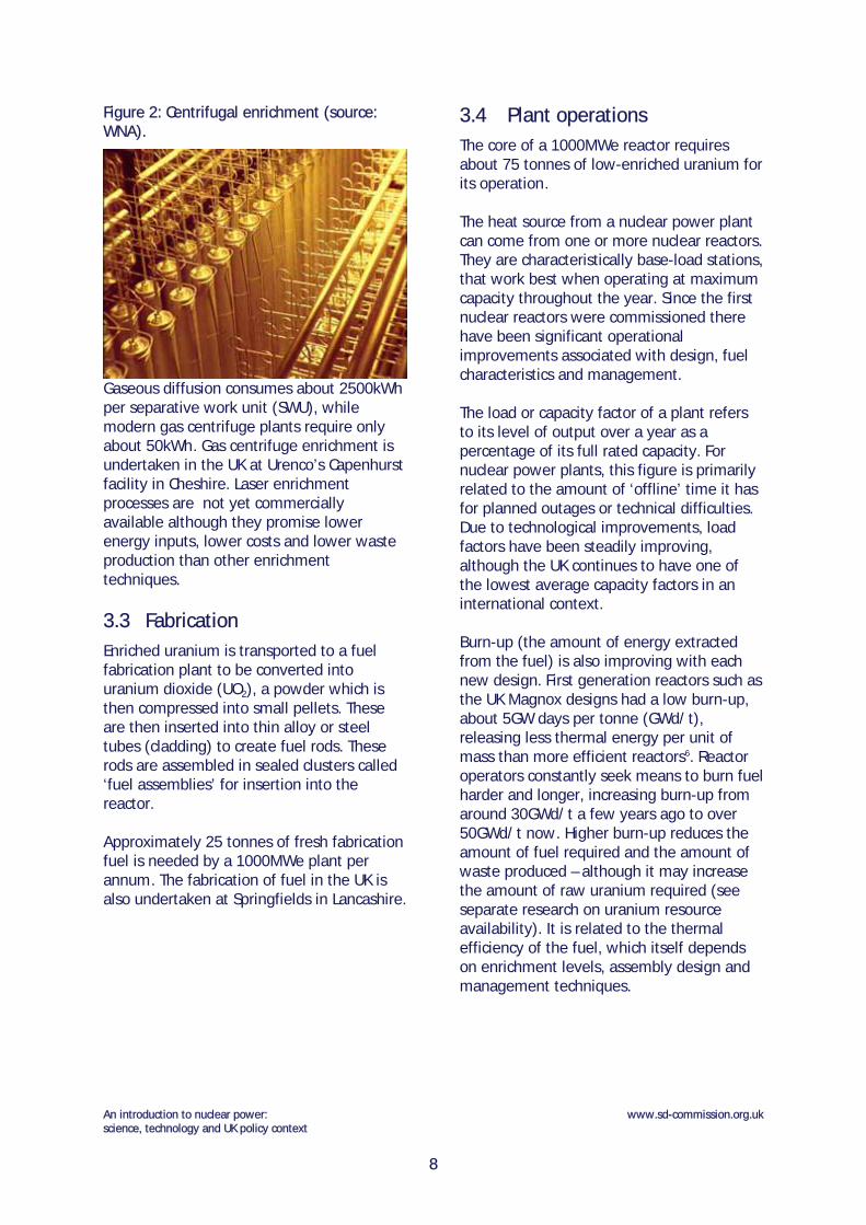
Figure 2: Centrifugal enrichment (source: WNA).
Gaseous diffusion consumes about 2500kWh per separative work unit (SWU), while modern gas centrifuge plants require only about 50kWh. Gas centrifuge enrichment is undertaken in the UK at Urenco’s Capenhurst facility in Cheshire. Laser enrichment processes are not yet commercially available although they promise lower energy inputs, lower costs and lower waste production than other enrichment techniques.
3.3 Fabrication
Enriched uranium is transported to a fuel fabrication plant to be converted into uranium dioxide (UO2), a powder which is then compressed into small pellets. These are then inserted into thin alloy or steel tubes (cladding) to create fuel rods. These rods are assembled in sealed clusters called ‘fuel assemblies’ for insertion into the reactor. Approximately 25 tonnes of fresh fabrication fuel is needed by a 1000MWe plant per annum. The fabrication of fuel in the UK is also undertaken at Springfields in Lancashire.
3.4 Plant operations
The core of a 1000MWe reactor requires about 75 tonnes of low-enriched uranium for its operation. The heat source from a nuclear power plant can come from one or more nuclear reactors. They are characteristically base-load stations, that work best when operating at maximum capacity throughout the year. Since the first nuclear reactors were commissioned there have been significant operational improvements associated with design, fuel characteristics and management. The load or capacity factor of a plant refers to its level of output over a year as a percentage of its full rated capacity. For nuclear power plants, this figure is primarily related to the amount of ‘offline’ time it has for planned outages or technical difficulties. Due to technological improvements, load factors have been steadily improving, although the UK continues to have one of the lowest average capacity factors in an international context. Burn-up (the amount of energy extracted from the fuel) is also improving with each new design. First generation reactors such as the UK Magnox designs had a low burn-up, about 5GW days per tonne (GWd/t), releasing less thermal energy per unit of mass than more efficient reactors6. Reactor operators constantly seek means to burn fuel harder and longer, increasing burn-up from around 30GWd/t a few years ago to over 50GWd/t now. Higher burn-up reduces the amount of fuel required and the amount of waste produced – although it may increase the amount of raw uranium required (see separate research on uranium resource availability). It is related to the thermal efficiency of the fuel, which itself depends on enrichment levels, assembly design and management techniques.
An introduction to nuclear power: science, technology and UK policy context
www.sd-commission.org.uk
8

Figure 3: Illustration of the basic operations of a standard PWR plant. The turbine building and control centre are separate from the reactor containment (source: US Nuclear Regulatory Commission).
An introduction to nuclear power: science, technology and UK policy context
www.sd-commission.org.uk
9

4 THE FUEL CYCLE: BACK END
4.1 Reprocessing
Around one third of fuel is removed from the reactor every 12-18 months to maintain performance. About 95% of this spent fuel is fertile U-238, but there are small proportions of fissile U-235 that did not fission inside the reactor. Additionally, about 1% is plutonium and the remaining 3% consists of highly radioactive fission products. Reprocessing involves separating spent fuel into uranium, plutonium and ‘waste containing fission products’, a process termed as ‘partitioning’. The uranium and plutonium can be recycled into fresh fuel, significantly reducing total waste quantities. This is done through a chemical process known as PUREX, which dissolves the fuel cladding in acid to separate the material. Uranium can be returned to the conversion plant to be further enriched to between 3-4% U-235, whilst plutonium can be used to produce mixed-oxide fuel (MOX). The remaining 3% is high-level radioactive waste, actinides which are vitrified with boron and sealed in cold storage, alongside the acids used in the PUREX process. In the UK, BNFL developed a reprocessing-based fuel cycle for its fleet of Magnox and Advanced Gas Cooled (AGR) reactors, although its most modern plant, Sizewell B (a PWR), does not currently have its fuel reprocessed as this is seen as an unnecessary expense while uranium prices remain low. The UK undertakes reprocessing activities at its Thermal Oxide Reprocessing Plant (THORP) at Sellafield, with was designed to reprocess spent fuel for the UK and under international contracts. Its future is currently uncertain due to low uranium prices and following a liquid effluent leak reported in April 2005.
4.1.1 MOX fuel
MOX fuel is a means to ‘burn up’ the plutonium that resides in spent fuel. It is fabricated by combining the depleted uranium from an enrichment plant with plutonium oxides. In this combination the plutonium is a substitute for the U-235 normally found in the fuel. If 7% of plutonium (Pu-239) is used, it is the equivalent to uranium fuel enriched to about 4.5%. The fabrication process is usually undertaken as soon as possible because of the fast decay capabilities of plutonium. Currently, 32 reactors in Europe are licensed to use MOX fuel and all modern Western reactors have the capability for at least 30% utilisation . MOX provides about 2% of the fuel used in reactors today, although this proportion continues to increase7. A MOX fabrication plant is currently under construction in Sellafield, Cumbria, due to be given consent to operate in November 2005.
4.2 Waste storage and disposal
All fuels used in the thermal generation of electricity produce wastes. However, the radioactive nature of nuclear fission requires that these wastes be managed in a safe and environmentally benign manner. There are three principles adopted for the management of potentially radioactive wastes: concentrate and contain, dilute and disperse, delay and decay – the latter principle is unique to nuclear waste strategies. Each country categorises waste differently according to their policy. The UK focuses on low-level wastes (LLW), intermediate-level wastes (ILW) and high-level wastes (HLW). Solutions for the long-term management of radioactive wastes in the UK are currently being considered by the Committee on
An introduction to nuclear power: science, technology and UK policy context
www.sd-commission.org.uk
10

Radioactive Waste Management (CoRWM), which is due to report to Government in July 2006. This issue is the focus of a separate study looking solely at waste and decommissioning. 4.2.1 Low-level wastes (LLW)
Also generated from hospitals and industry, these wastes are mainly treated as radioactive for precautionary reasons. LLW consists of potentially contaminated materials used in the vicinity of the reactor such as paper towels, scrap metal or clothing. These have been disposed of in Britain at Sellafield’s Drigg facility since 1959, stored in compact steel containers in a shallow repository. 4.2.2 Intermediate-level wastes (ILW)
The definition of ILW varies widely according to national policy and is the most problematic category of waste. These wastes are more radioactive than LLWs but do not have self-heating properties. They include fuel cladding or reactor components. In some cases, waste is categorised according to its half-life, although this technique has not been adopted in the UK. Currently ILW arising at Sellafield is immobilised with cement and stored in steel vaults at ground-level. 4.2.3 High-level wastes (HLW)
High-level waste in Britain is defined by its self-heating properties caused by isotope decay. It can be spent fuel or the liquid products arising from reprocessing. Spent fuel assemblies taken from the reactor are extremely hot from decay heat and are highly radioactive. Uranium-235 and plutonium-239 in particular, cannot easily be separated from their fuel cladding because of this intense radioactivity.
Figure 4: Plutonium storage area (source: University of Colorado).
Conditioning this waste involves vitrifying it with boron, an effective neutron absorber. Plutonium cannot effectively be vitrified so this resides as a problematic material to be used or disposed of in an appropriate manner. The vitrified waste is stored in steel canisters in on-site storage ponds or cooled, dry storage facilities, often for many years to disperse the heat and radioactivity before final disposal or reprocessing. In the UK, the Nuclear Decommissioning Authority is responsible for the disposal of HLW. These storage techniques are generally only intended as an interim solution until waste is easier to handle and a long-term management strategy is devised. Storing spent fuel for 50 years or more is generally viewed as sensible, to allow the total decay activity and self-heating to decrease, facilitating easier final disposal. There are two long-term options available for spent fuel disposal, reprocessing to recover a portion of it or indefinite disposal – these issues are currently being considered by CoRWM.
An introduction to nuclear power: science, technology and UK policy context
www.sd-commission.org.uk
11

Figure 5: Storage pond for spent fuel (source: World Nuclear Association).
4.2.4 Other radioactive materials
Several problematic materials including depleted uranium, plutonium and naturally occurring radioactive materials are not currently classified as waste in the UK8. Depleted uranium is the product of the enrichment process, a supply of uranium with significantly less fissile U-235 than can be found in natural ores. It has limited industrial uses, although it can be used in MOX fuel fabrication. It has low radioactivity, but storage and disposal remain a consideration.
An introduction to nuclear power: science, technology and UK policy context
www.sd-commission.org.uk
In 1999, it was estimated that the UK possessed about 100,000 tonnes of depleted uranium. Since the closure of the UK’s fast breeder reactor programme in 1994, separated plutonium, another problematic product of the fuel cycle, has become less useful. To prevent proliferation, calls have been made to mix surplus plutonium in MOX fuel, or to reclassify separated plutonium as a spent fuel and treat it as HLW.
4.3 Decommissioning
The decommissioning of a power plant after closure ideally involves returning the site as much as possible for normal use. This includes safe waste and component management, decontamination, dismantling, demolition and site remediation.
Firstly, this involves removing contaminated equipment and materials and placing nuclear fuel into temporary storage. These components are the most radioactive and represent the greatest hazard to workers and the environment. Once this is complete, the remaining radioactivity must be reduced to harmless levels through clean-up9. Surfaces are decontaminated using physical, electrical and ultrasonic processes and the waste sent to LLW storage sites. Modern plants are required to keep detailed records to ensure the decontamination is comprehensive, and specialised software is utilised to facilitate this process10.
Figure 6: Decommissioning activities at Sellafield (source: BNFL)
There are three options available following the closure of a power plant: total decommissioning, safe storage or entombment11. The former strategy involves the dismantling and decontamination of all
12

components and buildings, whilst safe storage involves sealing the intact facility for about 50 years to allow radioactive decay. Entombment is the indefinite concrete encasement of the reactor and surrounding area, maintained until an effective disposal solution is devised. The Nuclear Decommissioning Authority (NDA) is responsible for the UK’s nuclear legacy, and it currently estimates the cost of
dealing with existing legacy sites at £56bn12. As many civil reactors are now closed or nearing the end of their lifetime, it is necessary to have an effective strategy in place to decommission these facilities. However, older designs did not consider the practicalities of this process and thus is it is a complex and expensive task for the NDA. Each plant is currently undergoing different stages of commissioning, from de-fuelling to long-term care and maintenance.
An introduction to nuclear power: science, technology and UK policy context
www.sd-commission.org.uk
13

5 NUCLEAR TECHNOLOGIES Much of the information below has been obtained from W. Nuttall’s book on nuclear power13. A more detailed summary of nuclear technologies can be found there.
5.1 Past technologies - generations I & II 14
First generation reactors were early prototypes developed in the 1950s and 60s, often from earlier military purpose reactors. In the 1940s, British attempts to develop plutonium-based weapons provided experience with graphite-moderated reactors, later to be developed for commercial use. European countries, namely the UK and France, focused on gas-cooled technology for their original fleet while the US research programme built water-cooled reactors from the outset. Calder Hall was the first nuclear power station in the UK, a Magnox design that went on-line in 1956. 5.1.1 Magnox 15
A British design, the Magnox reactor is a pressurised CO2-cooled, graphite moderated design that uses natural uranium as fuel. The name is derived from the magnesium alloy used in the fuel cladding, an anagram of ‘magnesium non-oxidising’. Magnesium has the benefit of having low-neutron absorption, but it also limits the maximum temperature and consequently the efficiency of the plant. The initial design evolved from military efforts to separate plutonium. This process was only achievable with a low-temperature, short fuel cycle, making initial transitions of this design to commercial use uneconomic. The expense came from the measures needed to optimise heat transfer as well as those needed to handle waste. The fuel cladding reacts with damp air and water, preventing long-term storage of spent fuel. Instead waste had to be immediately reprocessed, initially
underwater until a dry handling process was developed in the 1970s. At this point the waste was highly radioactive requiring costly remote handling facilities. Nevertheless the plants themselves were considered relatively safe, because of the low power density and pressure, heavy design, and non-radioactive gas cooling system. Online refuelling also facilitated availability. For each new plant, the design was continuously refined, making alterations to the pressure levels and containment structure. In total, 11 Magnox power stations containing 26 units were built in the UK, with two exported to Japan and Italy. North Korea also developed three Magnox reactors based on the UK design and France focused on gas-cooled technology with its nine ‘UNGG’ plants, modelled on UK Magnox technology but using magnesium-zirconium alloy. The design is now obsolete, and the UK is the only country to still have any Generation I reactors operational, its remaining four Magnox plants due to close in the next five years. 5.1.2 Advanced gas-cooled reactor
(AGR)
After 15 years, the UK’s Magnox programme was superseded by advanced gas-cooled technology. Second-generation water-cooled designs were also being developed elsewhere at this time. A series of Advanced Gas-cooled Reactors (ACR) were commissioned in Britain between 1976 and 1988. The AGR’s are large, CO2-cooled, graphite moderated reactors, but they use stainless
An introduction to nuclear power: science, technology and UK policy context
www.sd-commission.org.uk
14

steel cladding in place of magnesium. The fuel is uranium oxide, enriched to between 2.5-3.5% because of the higher neutron absorption of steel. The plant operates by circulating CO2 through the core then passing it through steam generator tubes within the vessel. AGR’s have a good thermal efficiency but lower fuel burn-up, and the reactor size needs to be several times larger than a water-cooled design to give the same power output16. Cost over-runs and design problems typified the initial construction of this fleet. As with Magnox reactors, online fuelling is possible, but after the fuelling process, spent AGR fuel can be stored indefinitely. Nevertheless, reprocessing of this fuel was also desirable, and was the basis of a decision to build the THORP reprocessing plant in Sellafield. AGR’s therefore have the ability to operate in a closed-cycle, to deal with the large amounts of civil plutonium derived from the processes. Currently, there are seven generating AGR’s in the UK all owned by British Energy, but they represent the last ‘home-grown’ British reactor design – no reactors have been domestically produced since. 5.1.3 Pressurised water reactor (PWR)
Due to concerns over safety and financial austerity, UK nuclear build abruptly declined in the 1980s. A new generation II reactor at Sizewell, Suffolk, was the only one to be taken forward for development throughout the whole decade. This pressurised water reactor (PWR) uses light water for both the coolant and the neutron moderator. The design originated from nuclear submarine technology, but is now the most widespread commercial design in the world. The PWR uses enriched uranium typically arranged into 150-250 fuel bundles. Water flows around the fuel assembly and when fission occurs the latent heat transfers to the steam generator through a heat exchange.
There are various other types of Generation II water-cooled reactors, including the Boiling Water Reactor (BWR) and the Canadian CANDU Heavy Water Reactor (HWR). The US research programme has always focused on water-cooled technology, also adopted by the French in the 1970s. Sizewell B however, commissioned in 1995, is the UK’s only water-based design. The plant is designed by the US company Westinghouse, although significant safety modifications were made to it by UK regulators. It has the capacity to use MOX fuel, and its spent fuel can be reprocessed by THORP, although neither of these are currently undertaken for economic reasons while the price of uranium ore remains low. Today, twelve nuclear power units operate in the UK, four Magnox reactors, seven AGR’s and the Sizewell B PWR. Generation I reactors are scheduled for closure and there are currently no plans for new-build. The Magnox, AGR and PWR reactors are the three technologies from which the UK holds its experience today but the designers of the British gas-cooled reactors have no current interest in tendering for new-build. It seems next generation technologies will come from international competitors.
5.2 Near term technologies – generations III & III+
Generation III and III+ water-cooled technologies are currently being developed for new-build programs. Generation III designs are advanced light water reactors developed during the 1990s, of which the European Pressurised Water Reactor (EPR) and the Advanced Passive 600 (AP600) are examples. Generation III+ on the other hand are more recent developments of these initial designs intended for deployment by 2010, the Advanced Passive 1000 as an extension of its lower capacity predecessor and the Advanced CANDU Reactor as a developed model of the Canadian CANDU-6 designs.
An introduction to nuclear power: science, technology and UK policy context
www.sd-commission.org.uk
15

Both generations of reactors are evolutionary, not revolutionary, building on the design experience of similar models. They have also been developed to be more competitive in cost and efficiency than before, to cope with increasingly liberalised electricity markets. New-build is likely to consist of fleets of identical reactors, to ensure sufficient economies of scale. In the UK, domestic companies hold little recent development experience, their research and design activities curtailed as a result of the cost, inefficiency and image problems associated with British nuclear power. Instead, any competitive tendering for new-build contracts is likely to come from abroad, where international expertise has been at the forefront of near-term reactor design. The following three technologies are most likely to be involved in bids for near-term UK development. 5.2.1 Advanced CANDU reactor (ACR-
700 & ACR-1000) 17
The Advanced CANDU reactor is designed by Atomic Energy Canada Ltd (AECL). CANDU stands for the Canadian Deuterium Uranium reactor, a technology established since 1962. The ACR is a next generation passive reactor, building on the expertise from past CANDU designs18. It uses an innovative light water cooled, heavy water moderated system that differs from conventional designs through its use of a calandria. This vessel contains hundreds of pressure tubes that circulate the heavy water inside the calandria creating the conditions for a fission reaction. This is in contrast to conventional PWR’s that use a single high pressure vessel for this process. Nevertheless, 75% of PWR and ACR components are the same19. The main benefits of CANDU technology are the cost savings made from the use of a low-pressure vessel and the ability to re-fuel during full power operation. Modular construction techniques are also applied. The
ACR has a much smaller calandria than the older CANDU design, reducing cost and fuel requirements by 75%. In comparison to standard CANDU designs, this Generation III+ reactor uses slightly enriched fuel (~2%), rather than natural uranium, as this was found to be less efficient. It can also use MOX fuel. The advanced design can achieve very high burn-ups, making it possible to derive energy from spent PWR fuel. Termed the DUPIC process, this use of spent fuel would allow for both PWR and ACR reactors designs to exist in tandem, although currently it is a highly complex, expensive and high-risk activity20. Most ACR prototypes are based on a two-unit reactor plant with an operating life of 60 years, assuming replacement of the fuel channels and plant refurbishment after 30 years. The current size of the ACR is 700Mwe, although AECL are working on a higher capacity 1000MWe reactor. In November 2001, AECL and British Energy agreed to assess the feasibility of the ACR-700 for the UK market. Licensing is also being considered in Canada and Japan. 5.2.2 Advanced passive series (AP600
& AP1000) 21
The advanced passive series of reactors has been developed in the United States by Westinghouse, a subsidiary of BNFL Plc. Westinghouse already has construction experience in the UK, from the Sizewell B PWR. The AP600 is a reactor with a 600MWe output, developed during the 1990s as part of the US Department of Energy Advanced Light Water Reactor (ALWR) Program. Following an extensive regulatory review, it received final design approval in 1998. However, it was discovered the AP600 would not be cost effective on the US market, so attempts were made to increase capacity using the same blueprint technology.
An introduction to nuclear power: science, technology and UK policy context
www.sd-commission.org.uk
16

The Westinghouse AP1000 is a larger variant of its 600MWe predecessor. It occupies the same reactor island footprint, but its larger capacity comes from the extra height of the containment building, housing a 14-foot reactor. The component differences in this latest design are mainly required to increase heat transfer, with a larger number of fuel assemblies and a larger steam generator. The whole design is said to improve on previous designs in terms of safety, construction, efficiency and improved economics. The main characteristic of both AP reactors is their passive design, using the natural laws of gravity, convection and compression. There are therefore fewer moving components than in an active reactor, reducing the risk of failure and costs of construction. Those components that do not use natural forces are fitted with a fail-safe. Construction periods are reduced due to the modularisation of the design. This enables the plant to be manufactured off-site in smaller modules and transported for construction in parallel stages. Like all PWRs, the AP1000 uses enriched fuel (~4%), but this design has a higher burn-up efficiency than older technologies. This reduces pressure on resource availability and reduces waste. The AP1000 can also use up to 100% MOX fuel. The Westinghouse AP1000 standard plant design is the first Generation III+ reactor to receive final design approval from a regulatory authority. The US Nuclear Regulatory Commission (NRC) approved the AP1000 in 2004 and it now awaits the final step of certification in December 2005 before it can be commercially operated there. 5.2.3 European pressurised water
reactor (EPR)22
The development of an EPR has been underway since 1989. It is an evolution of two recent technologies: the French N4
reactor and the German Konvoi design. Primarily financed by Electricité de France (EdF), the EPR is designed by Framatome ANP, a joint venture of the French company Areva and the German firm Siemens. Unlike the ACR and AP1000 designs, it is not a passive reactor, but uses active systems with safety enhancements such as stronger containment and core capture in the event of an accident. The EPR is said to operate with an overall efficiency of 36-37%, the highest to date for water reactors. Over the years, the reactor’s capacity has been increased to 1750MWe to increase economic competitiveness. The EPR is designed to optimise the use of fuel whilst minimising radioactive wastes and has a higher electrical power than most existing plants. Like the previous two designs it can also use MOX fuel and uses 15% less uranium per MWh output than previous European reactors. In 2003, TVO, a Finnish electricity company, agreed to construct an EPR reactor in Olkiluoto, Finland, the first positive expression for new-build in Europe in a decade23. The reactor is scheduled for operation by 2009, whilst another demonstration EPR is being constructed in La Flamanville, France, under the instruction of EdF.
5.3 Other generation III designs 24
5.3.1 The advanced boiling water reactor (ABWR)
The ABWR is General Electric’s evolutionary design of a standard boiling water reactor. Based on the concept that steam directly from the coolant drives the turbines, this design eliminates the need for complex moving parts such as the steam generator, creating a generally simplified and lower pressure system than the PWR. It is also highly efficient as there is less latent heat loss than would be the case for PWRs requiring liquid to steam conversion. The main drawback to the ABWR is the presence of radioactive water in all areas of
An introduction to nuclear power: science, technology and UK policy context
www.sd-commission.org.uk
17

the plant rather than just the reactor. Refuelling is also a more complex process. Nevertheless, the ABWR has been certified to meet European requirements for advanced reactors. It has improved construction and ease of maintenance than standard BWRs and is being developed in four different versions: 600MWe, 900MWe, 1350MWe and 1700 MWe. There are currently three 60-year plants operating in Japan under the instruction of Hitachi and Toshiba, with others under construction in Taiwan. In Sweden, Westinghouse is working with Scandinavian utilities to develop its evolutionary BWR 90+ (1500MWe) design to meet European requirements. 5.3.2 The economic & simplified BWR
(ESBWR)
The ESBWR is a 1390MWe European version of the Simplified Boiling Water Reactor also developed by General Electric. It is characterized by passive safety systems but uses the same principles as the ABWR. A 1500MWe version is also in the pre-application stage for NRC design certification in the USA.
Another passive BWR design is Framatome ANP’s SWR1000. In collaboration with German utilities the company has a 1000-1290 MWe reactor which now seeks US design certification. Based on the laws of gravity and convection in a similar manner to the Westinghouse AP series, the SWR1000 is simple, reliable and has a high burn-up rate. The manufacturer’s claim it is economically competitive and ready for commercial deployment26. 5.3.3 Other designs
There are various other projects underway across the world to develop next-generation water reactors. For example, the APR-1400 is a South Korean advanced pressurised water reactor, based on the US System 80+ design. The basic design was completed in 1999 with the first APR-1400 units currently at pre contract stage. Operation is expected by 2013. Similarly, an Indian project is underway to develop an advanced Heavy Water Reactor based on CANDU designs whilst Russian engineers are improving their V VER reactors.
Table 1: Characteristics of generation III reactors
Design name ACR AP100025 EPR Manufacturer AECL Westinghouse – BNFL Framatome ANP
Country of origin
Canada USA France / Germany
Type Pressurised heavy water (HWR)
Pressurised light water (PWR)
Pressurised light water (PWR)
Output 700 MWe 1117-1154 MWe 1750 MWe
Capacity 93% 93% 92%
Lifetime 60 years 60 years 60 years
Burn-up efficiency
21 GWd/te 21 GWd/te > 60 GWd/te
Construction period
36 months 36 months 57 months
Current construction
- - Finland
Potential market
Japan / USA / Canada USA / UK US / China / Europe
An introduction to nuclear power: science, technology and UK policy context
www.sd-commission.org.uk
18

5.3.4 The international reactor innovative & secure (IRIS)
The IRIS is an international collaborative PWR project. It involves the development of a PWR by a consortium of 21 organisations including the UK and led by Westinghouse. This design is unique because of its integral nature – all primary components are inside the reactor vessel. The 335MWe reactor is a medium-sized simple design incorporating modular construction and enhanced safety features. It is envisaged multiple reactors will be operated on a single site27. Fuel usage is ultimately designed to be 10% enriched uranium with the capacity to burn MOX fuel and fuel burn-up itself is more efficient, producing less waste. IRIS also holds the potential to engage in future desalination activities and district heating cogeneration. The project is currently in the preliminary design phases, and has applied for pre-licensing. Following certification, deployment is expected around 2012-201528. 5.3.5 The pebble bed modular reactor
(PBMR)
The PBMR in comparison is based on a high temperature gas reactor system with hot helium used to drive the turbine. Today, pebble bed technology is mainly being developed in South Africa, China and Russia, but has widespread potential. The PBMR differs from conventional reactors because of its use of Triso fuel. Approximately 15,000 low enriched uranium fuel particles are compacted at the core of a large pebble covered in three layers of graphite cladding. Hundreds of these are then poured into the reactor, leaving space for helium gas to circulate between the units. The PBMR is not designed to provide a base-load power source, but instead to produce high quality electricity for isolated communities. Its capacity for on-line fuelling is important for the continuous availability of
electricity. The modular design and low cost construction also enables plants to be established relatively easily in remote areas. The British utility BNFL has a 22.5% share in a South African PBMR project. The UK also has an affiliation, from past experiments at Winfrith, to another similar design – the prismatic reactor, which also uses Triso fuel arranged in graphite blocks rather than pebbles. The UK potential for either of these technologies is as yet unknown. One problem is the greater production of waste from Triso fuel reactors, another is the lack of a proper containment building in their design. The ‘load following’ nature of these designs suggests its use may be limited in the UK, unless nuclear capacity were to expand considerably.
5.4 Generation IV 29
Generation III and III+ deployments are expected to come to an end around 2030. It is considered unlikely that decisions on new-build can be deferred until Generation IV reactors are available, instead previous stages may be needed for a natural progression of skills, technology and public acceptance. In 2000, the Generation IV International Forum (GIF) was established, representing ten countries including the UK. Two years later they announced the selection of six reactor technologies suitable for deployment between 2010 and 2030, which they believe represent the future shape of nuclear power. Three technologies are fast reactor designs and all operate at higher temperatures than present reactors. Most include a closed fuel cycle to maximize fuel reserves and minimize waste30. Only two are thermal reactors similar to current designs, indicating a revolutionary advancement in technology for Generation IV plants. In 2004, the DTI, BNFL and the nuclear consultancy NNC decided three of the six chosen GIF technologies should be considered for the UK market. These are
An introduction to nuclear power: science, technology and UK policy context
www.sd-commission.org.uk
19

briefly described below. The other three options; the Molten Salt Reactor (MSR), the Supercritical Water-cooled Reactor (SCWR) and the Lead-cooled Fast Reactor (LFR) were less suited to the UK context. 5.4.1 Gas-cooled fast reactors (GFR)
The gas-cooled reactor is a highly efficient, helium-cooled design operating with a closed fuel-cycle. The helium used as a coolant directly drives the turbine to generate electricity. Japanese research has also focused on the potential for the process-heat generated to be used in hydrogen production. Building upon Generation III+ technology but based on the principles of older gas-cooled reactors like AGRs, the GFR is considerably more efficient than once-through gas-cooled reactors, with a two-fold increase in fuel to useful heat conversion. The closed cycle nature of this design reduces the waste produced and allows for a variety of fuels, including depleted uranium to be used in the process. This focus on reprocessing is in contrast to recent speculation over the decline in closed cycle activities in countries such as the UK. In the GFR prototype, a fuel treatment and fabrication plant is integrated with the reactor on-site. The UK could potentially use its expertise of gas-cooled reactors from its AGR fleet and build on research experience at Dounreay and Winfrith. An international GFR prototype is expected by 2025. 5.4.2 Sodium-cooled fast reactors (SFR)
This reactor is the most mature of all the listed GIF technologies, with attempts made to develop this design as far back as the 1950s, including by the UK. However, the technological challenges discouraged long-term pursuit of the SFR. Even now, the design is uneconomic given low uranium prices, and only when these prices increase may the SFR, as it currently stands, be competitive.
It does have a potential role in reprocessing of spent fuels. Using pyrochemical techniques it could provide a solution to the UK’s plutonium legacy and can exploit unused energy from spent PWR fuel. There are a number of fast reactor programmes operating around the world, including construction of the first of a series of five such reactors in India (based on the French Phoenix design), which is due to be commissioned in 2008-1031. 5.4.3 Very high temperature gas
reactors (VHTR)
The UK has a longstanding commercial experience with gas-cooled reactors (AGR & Magnox) as well as research expertise from the experimental High Temperature Gas-cooled Reactor (HTGR) at Winfrith during the 1960s. However, HTGR development was often hindered by engineering, funding and licensing problems, and much of the ambition exceeded prevailing technical capability. New HTGRs are said to be more cost effective and technologically feasible than previous designs. Developed as graphite-moderated, helium-cooled reactors, with a once-through fuel cycle, the VHTRs also have the potential to produce hydrogen. Japanese experiments have resulted in a design that could separate nuclear energy from the electricity industry, using the nuclear power component to fuel a ‘hydrogen economy.’ Effective use of process heat has also been explored in China, using the energy to improve the cleanliness of fossil fuels in a complementary energy system. 5.5 Fusion technology 32
Unlike the mature technology of fission, fusion has yet to be demonstrated as a commercial technology. Fusion involves the joining together of small, light atoms under high temperature and high-pressure conditions rather than splitting of heavy atoms as in fission. The energy produced from the change in state is much more
An introduction to nuclear power: science, technology and UK policy context
www.sd-commission.org.uk
20

pronounced in a fusion reactor. The leading civil application of this technology is called ‘magnetic confinement fusion’. It has roots in pre-1950s science and has experienced highs and lows of progress and interest throughout the past 50 years. Fusion technology itself holds significant potential as a clean form of base-load electricity generation. It has no stored nuclear energy and no long-lived radioactive waste. It is also inherently safe as only a small contribution of fuel is added to the system for a reaction. Any accident would be negligible outside the plant.
An introduction to nuclear power: science, technology and UK policy context
www.sd-commission.org.uk
Fusion research has facilitated international collaboration for decades. Firstly, the Joint European Torus (JET), a large tokamak built in Culham was established in the 1970s, followed by the creation of ITER in 1985, an international fusion programme between the USA, Japan, Russia and the EU (represented by Euratom). This project intended to develop the world’s first experimental fusion power plant. It exists today in a scaled-down form following financial difficulties in the US and Russia, and now South Korea and China are joint participants. The UK, alongside France, Germany, Russia and the US has a substantial fusion research
community keen to promote the political, social and environmental benefits of fusion technology. However, fusion research suffers from a permanent ’50-year promise’ - the suggestion that the commercial application of fusion power is always 50 years away and always has been. Recent suggestions have however been made to combat the lethargy with which investors and governments associate the industry. A ‘fast-track’ programme involving the simultaneous experimentation of components is hoped to reduce the lead time to below thirty years. In the UK, fusion research is based at the UKAEA facility in Culham, Oxfordshire. In the context of climate change and energy security debates, alongside the potential for ‘fast tracking’, the government has renewed its interest in fusion technology. Domestic expenditure on fusion is around £14m per annum (£6.8m to JET), alongside a £23.5m contribution to the EU Sixth Framework Programme which invests in ITER33. It is estimated that approximately £4m more is spent on fusion research than renewables R&D in the UK34. The last major funding cut for fusion was back in 1990, suggesting a long-term government commitment to this potential technology.
21

6 CIVIL NUCLEAR POLICY IN THE UK
6.1 UK timeline
The UK began its civil nuclear programme in the 1950s, with construction of Calder Hall beginning in 1953. This was the first of two prototypes of the Magnox nuclear power plant design, leading to a further nine full-scale plants which became progressively
An introduction to nuclear power: science, technology and UK policy context
www.sd-commission.org.uk
i Due to a recent lifetime extension
larger in size as the technology developed. They are gas-cooled using carbon dioxide (CO2). In 1964, the UK decided to develop an Advanced Gas Cooled (AGR) design, and seven of these were built in total.
Table 2: UK nuclear power stations in order of scheduled close date (sources: BNFL35, British Energy36, DTI37, NDA38).
No Power Station Capacity (MWe)
Commissioned Date
Close Date
Plant Type
Owner/ operator
Status
1 Berkeley 276 1962 1989 Magnox NDA/BNG Decommissioning 2 Hunterston A 500 1964 1989 Magnox NDA/BNG Decommissioning 3 Trawsfynydd 470 1965 1991 Magnox NDA/BNG Decommissioning 4 Hinkley Point A 470 1965 2000 Magnox NDA/BNG Decommissioning 5 Bradwell 300 1962 2002 Magnox NDA/BNG Defuelling 6 Calder Hall 194 1956 2003 Magnox NDA/BNG Defuelling 7 Chapelcross 196 1959 2004 Magnox NDA/BNG Entering defuelling 8 Sizewell A 420 1966 2006 Magnox NDA/BNG Operational 9 Dungeness A 450 1965 2006 Magnox NDA/BNG Operational 10 Oldbury 434 1967 2008 Magnox NDA/BNG Operational 11
Dungeness B 1110 1983
2018i AGR British Energy
Operational
12 Wylfa 980 1971 2010 Magnox NDA/BNG Operational 13
Hinkley Point B 1220 1976
2011 AGR British
Energy Operational
14 Hunterston B 1190
1976 2011
AGR British Energy
Operational
15 Hartlepool 1210
1983 2014
AGR British Energy
Operational
16 Heysham 1 1150
1983 2014
AGR British Energy
Operational
17 Heysham 2 1250
1988 2023
AGR British Energy
Operational
18 Torness 1250
1988 2023
AGR British Energy
Operational
19 Sizewell B 1188
1995 2035
PWR British Energy
Operational
22

The AGR programme suffered from a number of serious setbacks, including project and cost overruns. Many of these stem from the fact that each AGR was built by different private contractors, to varying designs, which constrained the opportunities for learning, and eliminated potential economies of scale. Meanwhile, both France and the US were proceeding with Pressurised Water Reactor (PWR) designs, with much greater standardisation. The problems with the AGR programme are well demonstrated by the construction of Dungeness B, which started construction in 1965, but only became operational in 1983. AGRs continue to suffer from a number of operational problems, leading to lower than average operational availability. In 1978 the Government decided that future nuclear plants would be of the PWR design. After a very long public inquiry between 1983-1985, work started on the UK’s first PWR plant at Sizewell B in 1987, which is based on a modified Westinghouse (US) design. Initial plans for a series of four identical PWRs were shelved, and only Sizewell B was eventually built. This was mainly due to the privatisation of the electricity generating sector in the late 1980s, followed by a 1994 White Paper on nuclear power which recommended that further public support for nuclear power in a liberalised market could not be justified. The Sizewell B project eventually cost almost twice its original estimate, with an eventual power price of 6.0p/kWh (2000 prices, 8% discount rate) compared to an expected price in 1995 of 3.5p/kWh39.
6.2 Current policy
Since construction of Sizewell B no further proposals for new nuclear capacity have been put forward, and current policy, as stated in the 2003 Energy White Paper (EWP), is defined as ‘Keeping the Nuclear
Option Open’ (KNOO). This involves a limited amount of support from the Government for continued nuclear research and the maintenance of the skills base, although concerns have been expressed that the UK is in serious danger of failing on the latter goal, with resulting impacts on the ability to commission and licence new plants40,41. More recently, the Government has announced a fresh review of energy policy, which will tackle the nuclear question directly42. At the time of the EWP, Ministers stressed the need “to strengthen the contribution from energy efficiency and renewable energy sources”43, whilst keeping open a possible future role for nuclear if it were needed to meet carbon targets. The implicit assumption was that nuclear might be needed if the combined efforts of renewable energy and energy efficiency were deemed to be insufficient. Meanwhile, the Government remains committed to a liberalised energy market, which was one of the four pillars of energy policy outlined in the EWP. The existence of a liberalised electricity sector makes the forward planning of generating capacity difficult for the Government to influence, as in theory the development of new plant and choice of technology is at the discretion of private developers and investors. It is generally considered to be unlikely that proposals for new nuclear capacity would come forward without some form of public support. This point is addressed in more detail in Paper 4 – The economics of nuclear power. In order to determine whether public support is justified, a large number of issues will need to be considered. These are dealt with in the detailed reports associated with this study.
An introduction to nuclear power: science, technology and UK policy context
www.sd-commission.org.uk
23

7 REFERENCES
An introduction to nuclear power: science, technology and UK policy context
www.sd-commission.org.uk
1 UIC (2004). Nuclear Power Reactors. Briefing Paper #64. Available at: http://www.uic.com.au/nip64.htm 2 Hewitt, G.F. & Collier, J.G. (2000). Introduction to Nuclear Power. London. Taylor & Francis. 3 UIC (2004). The Nuclear Fuel Cycle. Available at: http://www.uic.com.au/nfc.htm4 Nuclear Decommissioning Authority (2005). Loca ions. Available at: t http://www.nda.gov.uk5 UIC (2003). U anium Enrichment. Nuclear Issues Briefing Paper #33. Available at: rhttp://www.uic.com.au/nip33.htm6 Royal Society (1999). Nuclear Reactor Fuel – the cur ent s tuation. Available at: r i http://www.royalsoc.ac.uk7 World Nuclear Association (2003). Mixed Oxide Fuel (MOX). Available at: http://www.world-nuclear.org/info/inf29.htm8 POST (2005). Pos note: Managing the UK plutonium s ockpile. Available at: t thttp://www.parliament.uk/documents/upload/POSTpn237.pdf 9 World Nuclear Association (2002). Decommissioning of Nuclear Facilities. Available at: http://www.world-nuclear.org/wgs/decom/intro2.htm10 IAEA (2003). Decommissioning: Lessons to Learn. Bulletin 451, Article 6. Available at: http://www.iaea.org/Publications/Magazines/Bulletin/Bull451/article6.pdf11 Nuclear Energy Institute (2002). Decommissioning of Nuclear Power Plants. Available at: http://www.nea.org 12 Nuclear Decommissioning Authority (2005). Draft Stategy for Consultation. Available at: http://www.nda.gov.uk/documents/nda_draft_strategy_for_consultation_2005a.pdf 13 W. J. Nuttall (2005). Nuclear Renaissance: technologies and policies for the future of nuclear power. Institute of Physics, Bristol. 14 DTI (2003). History of Nuclear Energy in the UK. Available at: http://www.dti.gov.uk/energy/nuclear/technology/history.shtml15 UIC (2005). Nuclear Power in the United Kingdom. July. Available at: http://www.uic.com.au/nip84.htm16 Royal Society (1999). Nuclear Energy – The Future Climate. Available at: http://www.royalsoc.ac.uk/downloaddoc.asp?id=122117 AECL (2005). ACR: Advanced CANDU Reactor. Available at: http://www.aecl.ca
18 Hedges, K. (2002). The Advanced CANDU Reactor (ACR): Ready for the Emerging Market. ANES symposium. October. Available at: http://anes.fiu.edu/Pro/s6hed.pdf 19 AECL Technologies (2005). ACR: Features. Available at: http://www.aecltechnologies.com20 NRC (2003). AECL: ACR-700 Technical Description Ref: ML032030391. Available at: http://adamswebsearch.nrc.gov21 Westinghouse/ BNFL (2002). AP600 Available at: http://www.ap600.westinghousenuclear.com22 Areva (2004). EPR: The advanced nuclear reactor: press kit. Available at: http://www.framatome-anp.com23 Framatome (2003). Olkiluoto 3: An EPR Turnkey Project. Available at: http://www.framatome-anp.com24 UIC (2005). Advanced Nuclear Power Reactors. Nuclear Issues Briefing Paper #16. Available at: http://www.uic.com.au/nip16.htm 25 Westinghouse/BNFL (2004). AP1000. Available at: http://www.ap1000.westinghousenuclear.com
24

An introduction to nuclear power: science, technology and UK policy context
www.sd-commission.org.uk
26 Framatome ANP (2005). Innovative Reactor Designs: SWR1000. Available at: http://www.de.framatome-anp.com/anp/e/foa/anp/products/s11_2.htm27 Nuclear Energy Institute (2005) International Reactor Innovative & Secure (IR S) Project. Available at: Ihttp://www.nei.org28 Westinghouse (2005). Research A eas Available at: r . http://www.westinghousenuclear.com/A4c.asp29 US Dept of Energy Nuclear Energy Research Advisory Committee and the Generation IV International Forum (2002). A technology roadmap for the Generation IV Nuclear Energy Systems. (GIF-002-00) Available at: http://gif.inel.gov/roadmap/pdfs/gen_iv_roadmap.pdf30 UIC (2005). Generation IV Nuclear Reactors. UIC Briefing Paper #77 Available at: http://www.uic.com.au/nip77.htm31 Uranium Information Centre (2005). Fast neutron reacto s. Briefing sheet #98. Available at: rhttp://www.uic.com.au/nip98.htm 32 POST (2003). Postnote: Nuclear Fusion. July 2003 #192 Available at: http://www.parliament.uk/post/pn192.pdf33 UKAEA (1999). Evaluation of the UK Fusion Programme. Available at: http://www.ukaea.org.uk/about/uk_fusion.pdf34 Department of Trade and Industry (2002). Report of the Chief Scientific Adviser’s Energy Research Review Group.
35 BNFL (2005). Nuclear Sites website. Available at: http://www.nuclearsites.co.uk 36 British Energy (2005). British Energy website – Our power stations. Available at: http://www.british-energy.co.uk/pagetemplate.php?pid=8237 DTI (2005). Nuclear power generation development and the UK indus ry. Available at: thttp://www.dti.gov.uk/energy/nuclear/technology/history.shtml38 NDA (2005). NDA website – locations. Available at: http://www.nda.gov.uk 39 PIU (2002). The Energy Review – a Performance and Innovation Unit report. Available at: http://www.number-10.gov.uk/su/energy/20.html40 House of Commons Select Committee on Science & Technology (2003). Sixth Report. Available at: http://www.publications.parliament.uk/pa/cm200203/cmselect/cmsctech/386/38602.htm41 DTI (2002). Report on the Nuclear Skills Group. Available at: http://www.dti.gov.uk/energy/nuclear/skills/nsg.shtml42 DTI (2006). Our Energy Challenge: securing clean affordable energy for the long-te m. Available at: , rhttp://www.dti.gov.uk/energy/review/index.shtml43 DTI (2003). Speech by The Rt. Hon Patricia Hewitt at ERM-Green Alliance Environment Forum, 14. th July 2003. Available at: http://www.dti.gov.uk/ministers/speeches/hewitt140703.html
25
Related Documents