Edward and Anchor/Darling Nuclear Application Valves Experience In Motion

Welcome message from author
This document is posted to help you gain knowledge. Please leave a comment to let me know what you think about it! Share it to your friends and learn new things together.
Transcript

Edward and Anchor/DarlingNuclear Application Valves
Experience In Motion

2
Flowserve Edward and Anchor/Darling Valves • 1900 South Saunders Street, Raleigh, North Carolina 27603 • 1-800-225-6989 • 1-919-832-0525 • Fax 1-919-831-3369
We’ll Support YouFlowserve’s Flow Control Division is dedicated to providing continuous aftermarket support to our nuclear customers. Safety-related valves and parts are supplied in accordance with ASME Section III and 10 CFR 50 Appendix B on a routine basis; and more importantly, in support of refueling outages and forced outages at nuclear generating stations.
Flowserve engineers, with working knowledge of nuclear applications and requirements are available on a 24-hour basis to respond to phone calls from nuclear customers with critical outage and unforeseen forced outage help requirements. At Flowserve, we understand the necessity of maintaining critical-path schedules!
When you specify Flowserve nuclear safety-related valves, you can rest ensured that the ongoing support and technical backup you may need down the road will be available to you right now!
Flowserve’s Edward and Anchor/Darling valves are manufactured exclusively at our Raleigh, North Carolina, operation. Of the various Flowserve manufacturing facilities, the Flow Control Division’s Raleigh operation is a long-time holder of ASME Section III N and NPT stamps, as well as the National Board’s Nuclear Repair (NR) stamp.
We maintain a quality assurance system in accordance with ASME Section III and 10 CFR 50 Appendix B with controlled copies of our QA Manual available to nuclear customers. Non-destructive testing including radiography, liquid penetrant inspection, mag particle inspection, ultrasonic testing, PMI and mechanical property testing are performed in-house by ASNT/EN 473 qualified examiners and inspection personnel. Design reports, seismic reports, environmental qualification reports and certified drawings are prepared by Raleigh’s engineering department. Additionally, Flowserve’s Flow Control Division offers dedication of commercial-grade items by qualified inspection personnel based on engineering-prescribed critical characteristics and dedication methods.
Specify Flowserve Edward and Anchor/Darling valves for nuclear safety-related requirements to ensure strict adherence to applicable nuclear codes and standards, on-time delivery and continuing aftermarket parts support.

flowserve.com
3
Flowserve Edward and Anchor/Darling Valves • 1900 South Saunders Street, Raleigh, North Carolina 27603 • 1-800-225-6989 • 1-919-832-0525 • Fax 1-919-831-3369
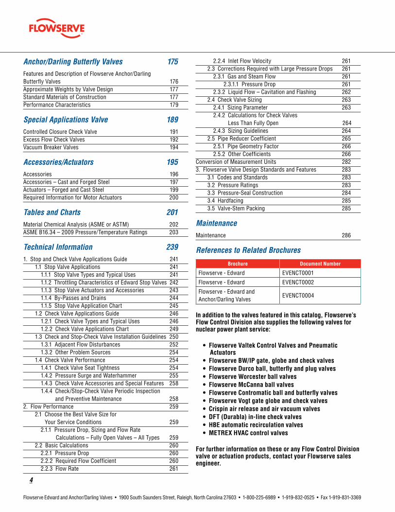
Table of ContentsEdward Figure Number Index 5Edward Valves Availability Chart 6Edward Description of Figure Number System 8Anchor/Darling Figure Number Index 10Anchor/Darling Valves Availability Chart 11Anchor/Darling Description of Figure Number System 14High Performance for Critical Service 16A History of Firsts 19Edward and Anchor/Darling Valves Available for Nuclear Service 20Edward Forged and Cast Steel Valves for Nuclear Service 21Checklist of Customer Information Required for Nuclear Valve Proposals 22Flowserve Edward Stored Energy Actuator 22Gas-Hydraulic Actuators for Fail-Safe Isolation Valves 23Main Steam and Main Feedwater Isolation Valves 24
Edward Gate Valves 25Features and Description of Edward Equiwedge Gate Valves 26Parts Specification List for Edward Gate Valves 27Features and Description of Edward Equiwedge Gate Valves 28Center Cavity Overpressurization 28
Anchor/Darling Gate Valves 35Features and Description of Anchor/Darling 800 Series Gate Valves 36Parts Specification List for Anchor/Darling 800 Series Gate Valves 37Features and Description of 1888 Series Double-Disc Gate Valves 39Parts Specification List for Anchor/Darling 1888 Series Double-Disc Gate Valves 40Features and Description of Double-Disc Gate Valves 42Parts Specification List for Double-Disc Gate Valves 43Features and Description of Anchor/Darling Flex-Wedge Gate Valves 49Parts Specification List for Anchor/Darling Flex-Wedge Gate Valves 50
Edward Globe and Stop-Check Valves 57Features and Description of Edward Bolted Bonnet Globe Valves 58Parts Specification List for Edward Bolted Bonnet Globe Valves 59Features and Description of Edward Univalve Globe Valves 62Parts Specification List for Edward Univalve Valves 63Features and Description of Edward Hermavalve Hermetically Sealed Valves 68Parts Specification List for Edward Hermavalve 70Features and Description of Edward Stop-Check Valves 72Parts Specification List for Edward Globe Valves, Stop-Check and Piston Lift Check 73
Features and Description of Edward Flite-Flow Globe Valves 74Special Application Valves 75
Anchor/Darling Globe Valves 89Features and Description of Anchor/Darling 800 Series Globe Valves 90Parts Specification List for Anchor/Darling 800 Series Globe Valves 91Features and Description of 1878 Series Globe Valve 94Parts Specification List for Anchor/Darling 1878 Series Globe Valves 95Features and Description of Flowserve Anchor/Darling Globe Valves 100Custom-Designed Plugs 101Power-Actuated Globe Valves 101Parts Specification List for Anchor/Darling Globe Valves 102
Edward Check Valves 109Controlled Closure Check Valve 113Features and Description of Flowserve Edward Check Valves 114Features and Description of Flowserve Edward One-Piece Tilting-Disc Check Valves 115Parts Specification List for Edward One-Piece Tilting-Disc Check Valve 116
Anchor/Darling Check Valves 127Features and Description of 800 and 1878 Series Piston Check Valves 129Parts Specification List for Anchor/Darling 800 and 1878 Piston Check Valves 130Features and Description of 1878 Series Swing-Check Valves 134Parts Specification List for Anchor/Darling 1878 Swing-Check Valves 135Features and Description of Anchor/Darling Check Valves 138Parts Specification List for Flowserve Anchor/Darling Tilting-Disc Check Valves 140Parts Specification List for Flowserve Anchor/Darling Swing Check Valves 141Parts Specification List for Flowserve Anchor/Darling Lift Check Valve 142
Anchor/Darling Ball Valves 153Features and Description of Flowserve Anchor/Darling Ball Valves 154Parts Specification List for Anchor/Darling Ball Valves 155
4
Flowserve Edward and Anchor/Darling Valves • 1900 South Saunders Street, Raleigh, North Carolina 27603 • 1-800-225-6989 • 1-919-832-0525 • Fax 1-919-831-3369
Anchor/Darling Butterfly Valves 175Features and Description of Flowserve Anchor/Darling Butterfly Valves 176Approximate Weights by Valve Design 177Standard Materials of Construction 177Performance Characteristics 179
Special Applications Valve 189Controlled Closure Check Valve 191Excess Flow Check Valves 192Vacuum Breaker Valves 194
Accessories/Actuators 195Accessories 196Accessories – Cast and Forged Steel 197Actuators – Forged and Cast Steel 199Required Information for Motor Actuators 200
Tables and Charts 201Material Chemical Analysis (ASME or ASTM) 202ASME B16.34 – 2009 Pressure/Temperature Ratings 203
Technical Information 2391. Stop and Check Valve Applications Guide 241
1.1 Stop Valve Applications 2411.1.1 Stop Valve Types and Typical Uses 2411.1.2 Throttling Characteristics of Edward Stop Valves 2421.1.3 Stop Valve Actuators and Accessories 2431.1.4 By-Passes and Drains 2441.1.5 Stop Valve Application Chart 245
1.2 Check Valve Applications Guide 2461.2.1 Check Valve Types and Typical Uses 2461.2.2 Check Valve Applications Chart 249
1.3 Check and Stop-Check Valve Installation Guidelines 2501.3.1 Adjacent Flow Disturbances 2521.3.2 Other Problem Sources 254
1.4 Check Valve Performance 2541.4.1 Check Valve Seat Tightness 2541.4.2 Pressure Surge and Waterhammer 2551.4.3 Check Valve Accessories and Special Features 258
1.4.4 Check/Stop-Check Valve Periodic Inspection and Preventive Maintenance 258
2. Flow Performance 2592.1 Choose the Best Valve Size for
Your Service Conditions 2592.1.1 Pressure Drop, Sizing and Flow Rate
Calculations – Fully Open Valves – All Types 2592.2 Basic Calculations 260
2.2.1 Pressure Drop 2602.2.2 Required Flow Coefficient 2602.2.3 Flow Rate 261
2.2.4 Inlet Flow Velocity 2612.3 Corrections Required with Large Pressure Drops 261
2.3.1 Gas and Steam Flow 2612.3.1.1 Pressure Drop 261
2.3.2 Liquid Flow – Cavitation and Flashing 2622.4 Check Valve Sizing 263
2.4.1 Sizing Parameter 2632.4.2 Calculations for Check Valves
Less Than Fully Open 2642.4.3 Sizing Guidelines 264
2.5 Pipe Reducer Coefficient 2652.5.1 Pipe Geometry Factor 2662.5.2 Other Coefficients 266
Conversion of Measurement Units 2823. Flowserve Valve Design Standards and Features 283
3.1 Codes and Standards 2833.2 Pressure Ratings 2833.3 Pressure-Seal Construction 2843.4 Hardfacing 2853.5 Valve-Stem Packing 285
MaintenanceMaintenance 286
References to Related Brochures
Brochure Document Number
Flowserve - Edward EVENCT0001
Flowserve - Edward EVENCT0002
Flowserve - Edward andAnchor/Darling Valves
EVENCT0004
In addition to the valves featured in this catalog, Flowserve’s Flow Control Division also supplies the following valves for nuclear power plant service:
•FlowserveValtekControlValvesandPneumatic Actuators •FlowserveBW/IPgate,globeandcheckvalves •FlowserveDurcoball,butterflyandplugvalves •FlowserveWorcesterballvalves •FlowserveMcCannaballvalves •FlowserveContromaticballandbutterflyvalves •FlowserveVogtgateglobeandcheckvalves •Crispinairreleaseandairvacuumvalves •DFT(Durabla)in-linecheckvalves •HBEautomaticrecirculationvalves •METREXHVACcontrolvalves
ForfurtherinformationontheseoranyFlowControlDivisionvalveoractuationproducts,contactyourFlowservesalesengineer.

flowserve.com
5
Flowserve Edward and Anchor/Darling Valves • 1900 South Saunders Street, Raleigh, North Carolina 27603 • 1-800-225-6989 • 1-919-832-0525 • Fax 1-919-831-3369
• These valves can be constructed for nuclear service. Note: See “References to Related Brochures” chart in the Table of Contents to locate figures that do not appear in this brochure.
Flowserve - Edward Figure Number IndexFigure Forged Cast Nuclear
158 57158Y 57160 58160Y 58238 63238Y 63303 28303Y 28304 28304Y 28318 26318Y 26319 26319Y 26329 26329Y 26338 63338Y 63391 30391Y 30394 30394Y 30393 30393Y 30
• 602 40 79• 602Y 40,44 79
604 39 78604Y 39 78605 39 78605Y 39 78606 39 78606Y 39 78607 39 78
• 607Y 39 78• 614 36 77• 614Y 36,43 77
616 35 76616Y 35 76617 35 76
• 617Y 35 76618 35 76618Y 35 76619 35 76619Y 35 76
• 670Y 41,42 117,118690 41 117690Y 41 117691 41 117691Y 41 117
• 692 41,42 117,118• 692Y 41,42,45 117,118
694 41 117694Y 41 117695 41 117695Y 41 117
• 702Y 40,44 79706Y 39 78707Y 39 78
• 714Y 36,43 77716Y 35 76717Y 35 76
• 770Y 41,42 117,118• 792Y 41,42,45 117,118
794Y 41 117795Y 41 117
• 828 28• 829 28
832 34832Y 34
• 838 33 110• 838Y 33 110• 846 29• 847 29• 848 31• 848Y 31 60• 849 31• 849Y 31 60• 858 30• 868 32• 868Y 32 61• 869 32• 869Y 32 61
Figure Forged Cast Nuclear• 970Y 52,53 119,121
1028 361029 361032 411032Y 411038 401038Y 401046 381047 381048 371048Y 371049 371049Y 371058 401068 391068Y 391069 391069Y 39
• 1302 29• 1302Y 29,33• 1314 27• 1314Y 27,32
1324 271324Y 271390 311390Y 311392 311392Y 31,341441 22,231441Y 22,231443 22,231443Y 22,23
• 1570Y 68 125• 1611 37,38 29,30• 1611BY 37,38 29,30• 1611Y 37,38 29,30
1641 24,251641Y 24,251643 24,251643Y 24,25
• 1711BY 37,38 29,30• 1711Y 37,38 29,30• 1911 48,49 31,32• 1911BY 48,49 31,32• 1911Y 48,49 31,32• 2002Y 63,64,70 86,87• 2006Y 63,64 86• 2007Y 63,64 86,87• 2014Y 59,60,69 84,85• 2016Y 59 84• 2017Y 59,60 84,85• 2070Y 68 125• 2092Y 65,67,71 122,124• 2094Y 65,66 122,123• 2095Y 65,66 122,123• 2570Y 81,83
3602Y 90,91• 3902Y 79,80,85• 3906 79• 3906Y 79• 3907 79,80• 3907Y 79,80• 3914Y 75,76,84• 3916 75• 3916Y 75• 3917 75,76• 3917Y 75,76• 3992Y 81,82,86• 3994 81• 3994Y 81• 3995 81,82• 3995Y 81,82• 4002 50,51 82,83• 4002Y 50,51,56 82,83• 4006 50 82• 4006Y 50 82• 4007 50,51 82,83• 4007Y 50,51 82,83• 4014 46,47 80,81• 4014Y 46,47,55 80,81• 4016 46 80• 4016Y 46 80
Figure Forged Cast Nuclear• 4017 46,47 80,81• 4017Y 46,47 80,81• 4092 52,54 119,120• 4092Y 52,54,57 119,120• 4094 52 119• 4094Y 52 119• 4095 52,53 119,120• 4095Y 52,53 119,120• 4302Y 50,51,56 82,83• 4306Y 50 82• 4307Y 50,51 82,83• 4314Y 46,47,55 80,81• 4316Y 46 80• 4317Y 46,47 80,81• 4370Y 52,53 119,121• 4392Y 52,54,57 119,120• 4394Y 52 119• 4395Y 52,53 119,121• 4402Y 79,80,85• 4406Y 79• 4407Y 79,80• 4414Y 75,76,84• 4416Y 75• 4417Y 75,76
4448Y 58• 4470Y 81,83• 4492Y 81,82,86• 4494Y 81• 4495Y 81,82
4498Y 584502Y 944514Y 924570Y 964592Y 955002Y 945014Y 925070Y 965092Y 955158 575160 58
• 7502Y 63,64,70 86,87• 7506 63 86• 7506Y 63 86• 7507 63,64 86,87• 7507Y 63,64 86,87• 7514Y 59,60,69 84,85• 7516 59 84• 7516Y 59 84• 7517 59,60 84,85• 7517Y 59,60 84,85
7548Y 58• 7592Y 65,67,71 122,124• 7594 65,66 122,123• 7594Y 65,66 122,123• 7595 65,66 122,123• 7595Y 65,66 122,123
7598Y 589158 579160 58
• 11511 61,62 33• 11511Y 61,62 33,34• 11511BY 61,62 33,34• 12011Y 61,62 33,34• 12011BY 61,62 33,34• 12511 77• 12511Y 77• 12511BY 77,78• 14311Y 48,49 31,32• 14311BY 48,49 31,32• 14411BY 77,78• 14411Y 77• 15004 71• 15008 71• 15014 71• 15018 71• 15104 71• 15108 71• 15114 71• 15118 71
16004 6716008 6716014 67
Figure Forged Cast Nuclear16018 6735125 2735129 2735225 2735229 27
• 36120 42• 36122 35• 36124 26,42,60 64
36125 45• 36128 26,42,60 64
36129 45• 36160 43• 36164 43 65
36165 46• 36168 43 65
36169 46• 36170 44• 36174 44 111
36175 47• 36178 44 111
36179 47• 36220 42• 36222 35• 36224 26,42,60 64
36225 45• 36228 26,42,60 64
36229 45• 36260 43• 36264 43 65
36265 46• 36268 43 65
36269 46• 36270 44• 36274 44 111
36275 47• 36278 44 111
36279 47• 66120 48• 66124 26,48,61 66
66125 51• 66128 26,48,61 66
66129 51• 66160 49• 66164 49 67
66165 52• 66168 49 67
66169 52• 66170 50• 66174 50 112
66175 53• 66178 50 112
66179 53• 66220 48• 66224 26,48,61 66
66225 51• 66228 26,48,61 66
66229 51• 66260 49• 66264 49 67
66265 52• 66268 49 67
66269 52• 66270 50• 66274 50 112
66275 53• 66278 50 112
66279 5396124 54,6296128 54,6296164 5596168 5596174 5696178 5696224 54,6296228 54,6296264 5596268 5596274 5696278 56DSXXXX 60,61,62DEXXXX 60,61,62DCXXXX 60,61,62
6
Flowserve Edward and Anchor/Darling Valves • 1900 South Saunders Street, Raleigh, North Carolina 27603 • 1-800-225-6989 • 1-919-832-0525 • Fax 1-919-831-3369
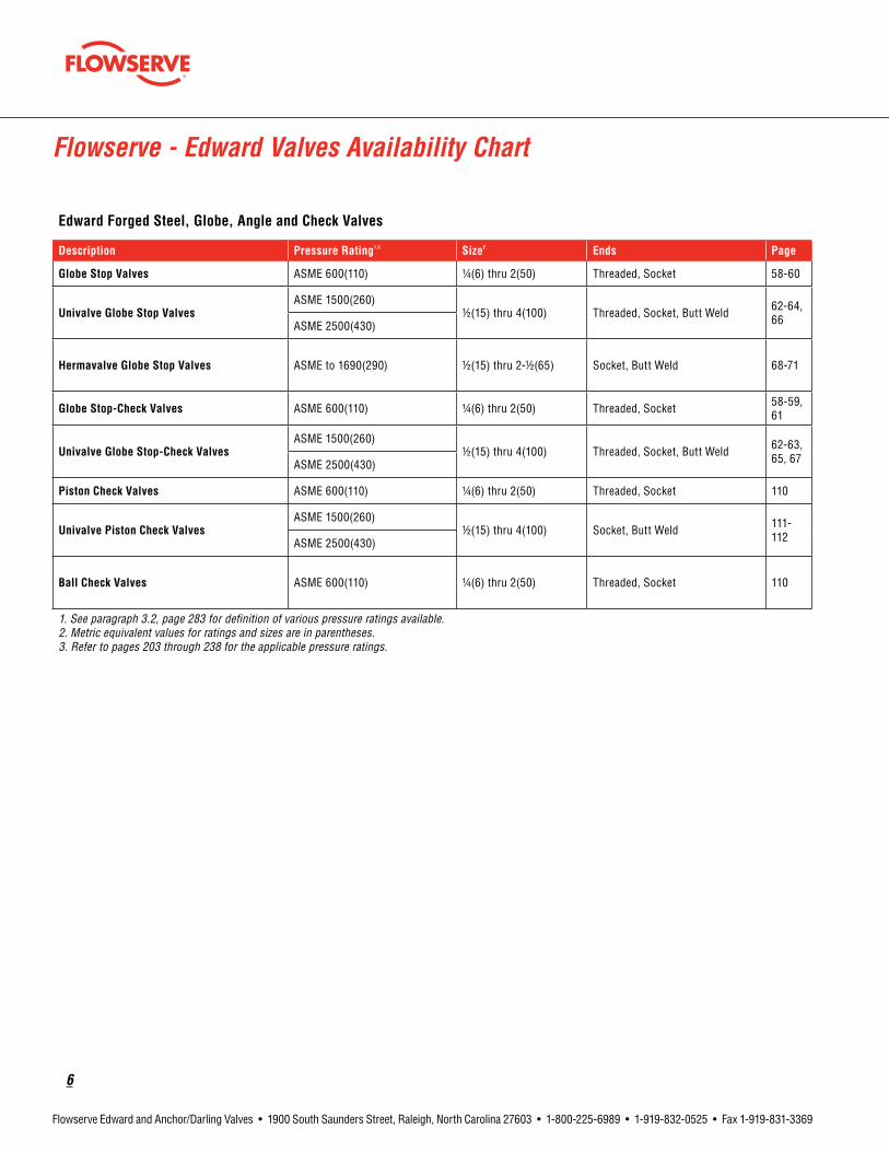
EdwardForgedSteel,Globe,AngleandCheckValves
Description PressureRating1,2 Size2 Ends Page
GlobeStopValves ASME 600(110) 1/4(6) thru 2(50) Threaded, Socket 58-60
UnivalveGlobeStopValvesASME 1500(260)
1/2(15) thru 4(100) Threaded, Socket, Butt Weld 62-64, 66ASME 2500(430)
HermavalveGlobeStopValves ASME to 1690(290) 1/2(15) thru 2-1/2(65) Socket, Butt Weld 68-71
GlobeStop-CheckValves ASME 600(110) 1/4(6) thru 2(50) Threaded, Socket 58-59, 61
UnivalveGlobeStop-CheckValvesASME 1500(260)
1/2(15) thru 4(100) Threaded, Socket, Butt Weld 62-63, 65, 67ASME 2500(430)
PistonCheckValves ASME 600(110) 1/4(6) thru 2(50) Threaded, Socket 110
UnivalvePistonCheckValvesASME 1500(260)
1/2(15) thru 4(100) Socket, Butt Weld 111- 112ASME 2500(430)
BallCheckValves ASME 600(110) 1/4(6) thru 2(50) Threaded, Socket 110
1. See paragraph 3.2, page 283 for definition of various pressure ratings available. 2. Metric equivalent values for ratings and sizes are in parentheses. 3. Refer to pages 203 through 238 for the applicable pressure ratings.
Flowserve - Edward Valves Availability Chart

flowserve.com
7
Flowserve Edward and Anchor/Darling Valves • 1900 South Saunders Street, Raleigh, North Carolina 27603 • 1-800-225-6989 • 1-919-832-0525 • Fax 1-919-831-3369
EdwardCastSteelGate,Globe,AngleandCheckValves
Description PressureRating1,2 Size2 Ends Page
BoltedBonnetGlobeandAngleValves,StopandStop-Check(Non-Return)andBoltedCoverPistonCheck
ASME 600(110) 2-1/2(65) thru 14(350) Butt Weld or Flanged 72, 76, 78, 114, 117
PressureSealBonnetGlobeandAngleValvesStopandStop-Check(Non-Return)
ASME 600(110) 2-1/2(65) thru 14(350) Butt Weld or Flanged
72, 76, 78
ASME 900(150) 3(80) thru 14(350) 72, 80, 82, 119, 120
ASME 1500(260) 2-1/2(65) thru 14(350) 72, 84, 86, 122, 123
PressureSealCover,PistonCheckValves
ASME 900(150) 3(80) thru 14(350) Butt Weld or Flanged
114, 119
ASME 1500(260) 2-1/2(65) thru 24(600) 72, 122, 123
Equiwedge®GateValvesASME 600(110) & 900(150) 2-1/2(65) thru 32(800) Butt Weld or
Flanged 26-32
ASME 1500(260) 2-1/2(65) thru 24(600) 26-28, 33-34
Flite-Flow®GlobeValves,StopandStop-Check(Non-Return)
ASME 600(110) 3(80) thru 32(800) Butt Weld or Flanged
72-74, 77, 79
ASME 900(150) 3(80) thru 16(400) 72-74, 81, 83
ASME 1500(260) 3(80) thru 24(600) 72-74, 85, 87
Flite-Flow®PistonCheckValves
ASME 600(110) 3(80) thru 32(800) Butt Weld or Flanged
114, 117, 118
ASME 900(150) 3(80) thru 16(400) 114, 119, 120
ASME 1500(260) 3(80) thru 24(600) 114, 122, 124
Tilting-DiscCheckValvesASME 600(110) 6(150) thru 20(500)
Butt Weld 115, 118
ASME 900(150) & 1500(260) 21/2(65) thru 24(600) 115, 121, 125
1. See paragraph 3.2, page 283 for definition of various pressure ratings available. 2. Metric equivalent values for ratings and sizes are in parentheses. 3. Refer to pages 203 through 238 for the applicable pressure ratings.
Flowserve - Edward Valves Availability Chart
8
Flowserve Edward and Anchor/Darling Valves • 1900 South Saunders Street, Raleigh, North Carolina 27603 • 1-800-225-6989 • 1-919-832-0525 • Fax 1-919-831-3369
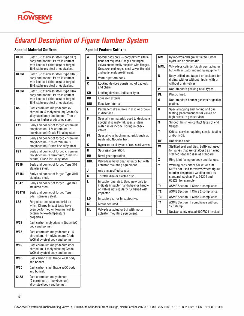
CF8C Cast 18-8 stainless steel (type 347) body and bonnet. Parts in contact with line fluid either cast or forged 18-8 stainless steel or equivalent.
CF3M Cast 18-8 stainless steel (type 316L) body and bonnet. Parts in contact with line fluid either cast or forged 18-8 stainless steel or equivalent.
CF8M Cast 18-8 stainless steel (type 316) body and bonnet. Parts in contact with line fluid either cast or forged 18-8 stainless steel or equivalent.
C5 Cast chromium molybdenum (5 chromium 1/2 molybdenum) Grade C5 alloy steel body and bonnet. Trim of equal or higher grade alloy steel.
F11 Body and bonnet of forged chromium molybdenum (1-1/4 chromium, 1/2 molybdenum) Grade F11 alloy steel.
F22 Body and bonnet of forged chromium molybdenum (2-1/4 chromium, 1 molybdenum) Grade F22 alloy steel.
F91 Body and bonnet of forged chromium molybdenum (9 chromium, 1 molyb-denum) Grade F91 alloy steel.
F316 Body and bonnet of forged Type 316 stainless steel.
F316L Body and bonnet of forged Type 316L stainless steel.
F347 Body and bonnet of forged Type 347 stainless steel.
F347H Body and bonnet of forged Type 347H stainless steel.
LF2 Forged carbon steel material on which Charpy impact tests have been performed on forging heat to determine low-temperature properties.
WC1 Cast carbon molybdenum Grade WC1 body and bonnet.
WC6 Cast chromium molybdenum (1-1/4 chromium, 1/2 molybdenum) Grade WC6 alloy steel body and bonnet.
WC9 Cast chromium molybdenum (2-1/4 chromium, 1 molybdenum) Grade WC9 alloy steel body and bonnet.
WCB Cast carbon steel Grade WCB body and bonnet.
WCC Cast carbon steel Grade WCC body and bonnet.
C12A Cast chromium molybdenum (9 chromium, 1 molybdenum) alloy steel body and bonnet.
A Special body only — body pattern altera-tions not required. Flanges on forged valves not normally supplied with flanges. On socket end forged steel valves the inlet and outlet ends are different.
B Venturi pattern body.
C Locking devices consisting of padlock and chain.
CD Locking devices, indicator type.
DD Equalizer external.
DDI Equalizer internal.
E Permanent drain, hole in disc or groove in disc face.
F Special trim material: used to designate special disc material, special stem material, or inconel spring in check valves.
FF Special yoke bushing material, such as Austenitic Nodular Iron.
G Bypasses on all types of cast steel valves
H Spur gear operation.
HH Bevel gear operation.
HHL Valve-less bevel gear actuator but with actuator mounting equipment.
J Any unclassified special.
K Throttle disc or skirted disc.
L Impactor operated. Used now only to indicate impactor handwheel or handle on valves not regularly furnished with impactor.
LD Impactorgear or Impactodrive.
M Motor actuated.
ML Valve-less actuator but with motor actuator mounting equipment.
MM Cylinder/diaphragm actuated. Either hydraulic or pneumatic.
MML Valve-less cylinder/diaphragm actuator but with actuator mounting equipment.
N Body drilled and tapped or socketed for drains, with or without nipple, with or without drain valves.
P Non-standard packing of all types.
PL Plastic lined.
Q Non-standard bonnet gaskets or gasket plating.
R Special lapping and honing and gas testing (recommended for valves on high pressure gas service).
S Smooth finish on contact faces of end flanges.
T Critical service requiring special testing and/or NDE.
UF Unfinished ends.
W Stellited seat and disc. Suffix not used for valves that are cataloged as having stellited seat and disc as standard.
X Ring joint facing on body end flanges.
Y Welding ends either socket or butt. Suffix not used for valves where figure number designates welding ends as standard, such as Fig. 36224 and 66228, for example.
T1 ASME Section III Class 1 compliance.
T2 ASME Section III Class 2 compliance.
T3 ASME Section III Class 3 compliance.
T4 ASME Section III compliance without “N” stamp.
T5 Nuclear safety related-10CFR21 invoked.
SpecialMaterialSuffixes SpecialFeatureSuffixes
Edward Description of Figure Number System

flowserve.com
9
Flowserve Edward and Anchor/Darling Valves • 1900 South Saunders Street, Raleigh, North Carolina 27603 • 1-800-225-6989 • 1-919-832-0525 • Fax 1-919-831-3369
XX1 alpha digit prefix Indicates design revision, if applicable.
2 alpha digits indicates style of pressure combo valve.
XXXXX3-5 digits figure number
(XXX)3-4 digits body material designation
XXXXXXX1 or more digits as required suffixes (see list)
Unless otherwise specified when ordering Edward valves, the standard material of construction for Forged products is A/SA105 Carbon Steel, and for Cast products is SA216 Grade WCB Carbon Steel.
Listed on page 8 are the letter suffixes used to indicate variations from standard construction, or special features (Ex. 618K, 7506 [WC6]Y, and 847 AH.)
When two or more suffixes follow a figure number, a definite suffix sequence is to be used.
The sequence is:
1) Special material (if applicable).
2) Other applicable feature suffixes in alphabetical order, except T1-T5, which are listed last.
7502 (WC6) B G J M N Y
Edward Description of Figure Number SystemExample
BUTT WELD ENDS
BODY DRAIN
MOTOR ACTUATED
SPECIAL REQUIREMENT (NEEDS TO BE SPECIFIED)
BYPASS
VENTURI BODY
BODY CAST MATERIAL GRADE
VALVE FIGURE NUMBER, STANDARD CLASS Y-GLOBE FLITE-FLOW
12 x 10 x 12
VALVE SIZE, 12 X 10 X 12-INCH, VENTURI BODY
10
Flowserve Edward and Anchor/Darling Valves • 1900 South Saunders Street, Raleigh, North Carolina 27603 • 1-800-225-6989 • 1-919-832-0525 • Fax 1-919-831-3369
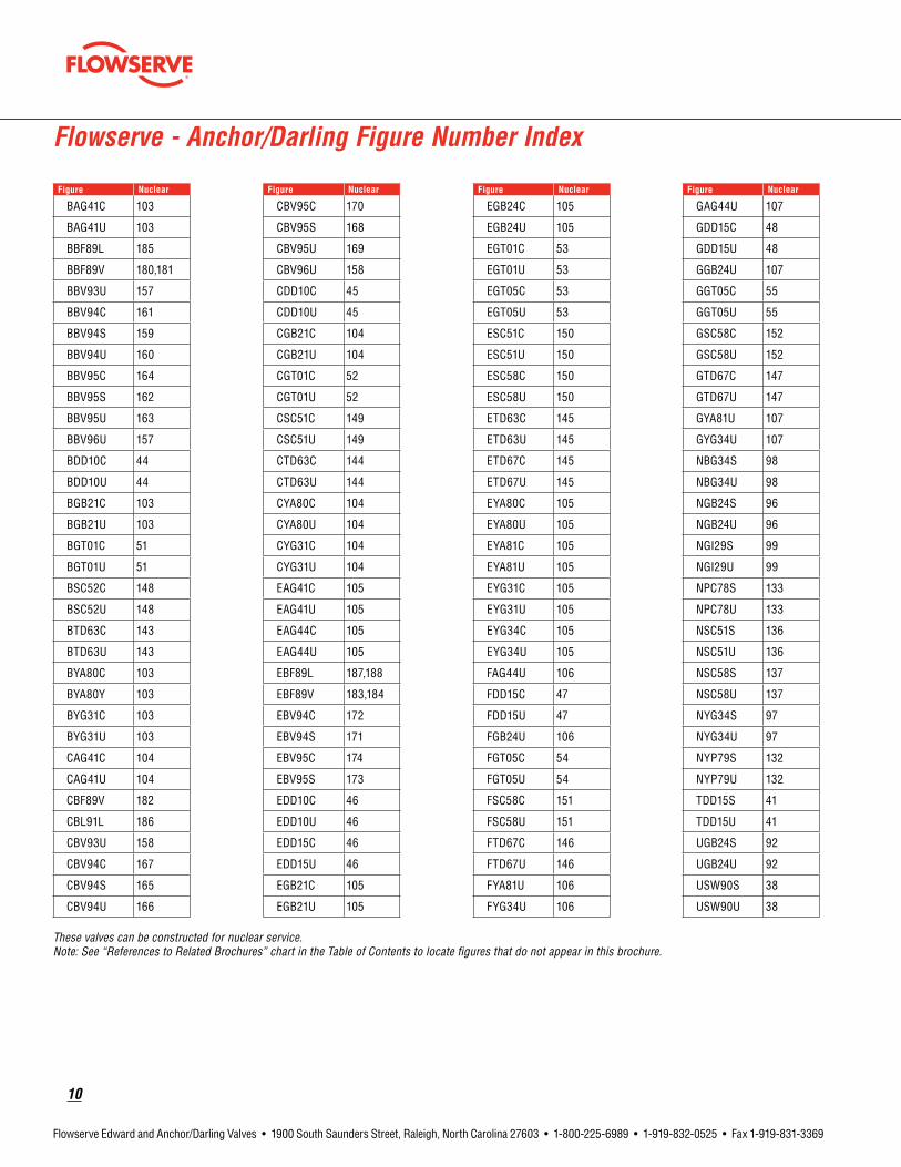
These valves can be constructed for nuclear service. Note: See “References to Related Brochures” chart in the Table of Contents to locate figures that do not appear in this brochure.
Flowserve - Anchor/Darling Figure Number Index
Figure Nuclear
BAG41C 103
BAG41U 103
BBF89L 185
BBF89V 180,181
BBV93U 157
BBV94C 161
BBV94S 159
BBV94U 160
BBV95C 164
BBV95S 162
BBV95U 163
BBV96U 157
BDD10C 44
BDD10U 44
BGB21C 103
BGB21U 103
BGT01C 51
BGT01U 51
BSC52C 148
BSC52U 148
BTD63C 143
BTD63U 143
BYA80C 103
BYA80Y 103
BYG31C 103
BYG31U 103
CAG41C 104
CAG41U 104
CBF89V 182
CBL91L 186
CBV93U 158
CBV94C 167
CBV94S 165
CBV94U 166
Figure Nuclear
CBV95C 170
CBV95S 168
CBV95U 169
CBV96U 158
CDD10C 45
CDD10U 45
CGB21C 104
CGB21U 104
CGT01C 52
CGT01U 52
CSC51C 149
CSC51U 149
CTD63C 144
CTD63U 144
CYA80C 104
CYA80U 104
CYG31C 104
CYG31U 104
EAG41C 105
EAG41U 105
EAG44C 105
EAG44U 105
EBF89L 187,188
EBF89V 183,184
EBV94C 172
EBV94S 171
EBV95C 174
EBV95S 173
EDD10C 46
EDD10U 46
EDD15C 46
EDD15U 46
EGB21C 105
EGB21U 105
Figure Nuclear
EGB24C 105
EGB24U 105
EGT01C 53
EGT01U 53
EGT05C 53
EGT05U 53
ESC51C 150
ESC51U 150
ESC58C 150
ESC58U 150
ETD63C 145
ETD63U 145
ETD67C 145
ETD67U 145
EYA80C 105
EYA80U 105
EYA81C 105
EYA81U 105
EYG31C 105
EYG31U 105
EYG34C 105
EYG34U 105
FAG44U 106
FDD15C 47
FDD15U 47
FGB24U 106
FGT05C 54
FGT05U 54
FSC58C 151
FSC58U 151
FTD67C 146
FTD67U 146
FYA81U 106
FYG34U 106
Figure Nuclear
GAG44U 107
GDD15C 48
GDD15U 48
GGB24U 107
GGT05C 55
GGT05U 55
GSC58C 152
GSC58U 152
GTD67C 147
GTD67U 147
GYA81U 107
GYG34U 107
NBG34S 98
NBG34U 98
NGB24S 96
NGB24U 96
NGI29S 99
NGI29U 99
NPC78S 133
NPC78U 133
NSC51S 136
NSC51U 136
NSC58S 137
NSC58U 137
NYG34S 97
NYG34U 97
NYP79S 132
NYP79U 132
TDD15S 41
TDD15U 41
UGB24S 92
UGB24U 92
USW90S 38
USW90U 38

flowserve.com
11
Flowserve Edward and Anchor/Darling Valves • 1900 South Saunders Street, Raleigh, North Carolina 27603 • 1-800-225-6989 • 1-919-832-0525 • Fax 1-919-831-3369
Anchor/DarlingSmallBore,Globe,GateandCheckValves
Description PressureRating1,2 Size2 Ends Page
GlobeStopValvesASME 800(130) 1/2(15) thru 2(50) Socket, Butt Weld 89-92
ASME 1878(310) 1/2(15) thru 2(50) Socket, Butt Weld 94-97
GateStopValvesASME 800(130)
1/2(15) thru 2(50) Socket, Butt Weld 36-38
ASME 1888(310) Socket, Butt Weld 39-41
BellowsGlobeStopValvesASME to 800 1/2(15) thru 2(50) Socket, Butt Weld 93
ASME to 1878(310) 1/2(15) thru 2(50) Socket, Butt Weld 98, 99
PistonCheckValvesASME 800 1/2(15) thru 2(50) Socket, Butt Weld 129 - 131
ASME 1878(310) 1/2(15) thru 2(50) Socket, Butt Weld 129, 130, 132, 133
SwingCheckValves ASME 1878 (310) 1/2(15) thru 2(50) Socket, Butt Weld 134-137
1. See paragraph 3.2, page 283 for definition of various pressure ratings available. 2. Metric equivalent values for ratings and sizes are in parentheses. 3. Refer to pages 203 through 238 for the applicable pressure ratings.
Flowserve - Anchor/Darling Valves Availability Chart

12
Flowserve Edward and Anchor/Darling Valves • 1900 South Saunders Street, Raleigh, North Carolina 27603 • 1-800-225-6989 • 1-919-832-0525 • Fax 1-919-831-3369
Anchor/DarlingCastSteelGate,Globe,AngleandCheckValves
Description PressureRating1,2 Size2 Ends Page
BoltedBonnetGlobe andAngleStopValves
ASME 150(25) 2-1/2(65) thru 24(600) Butt Weld or Flanged
100-103
ASME 300(50) 2-1/2(65) thru 24(600) 100-102, 104
ASME 600(110)* 2-1/2(65) thru 24(600) 100-102, 105
PressureSealBonnetGlobe andAngleStopValves
ASME 600(110) 2-1/2(65) thru 24(600) Butt Weld or Flanged
100-102, 105
ASME 900(150) 2-1/2(65) thru 24(600) 100-102, 106
ASME 1500(260) 2-1/2(65) thru 24(600) 100-102, 107
BoltedBonnetDouble-DiscGateValves
ASME 150(25)
2-1/2(65) thru 24(600) Butt Weld or Flanged
42-44
ASME 300(50) 42, 43, 45
ASME 600(110) 42, 43, 46
PressureSealBonnet Double-DiscGateValves
ASME 600(110)
2-1/2(65) thru 24(600) Butt Weld or Flanged
42, 43, 46
ASME 900(150) 42, 43, 47
ASME 1500(260) 42, 43, 48
1. See paragraph 3.2, page 283 for definition of various pressure ratings available. 2. Metric equivalent values for ratings and sizes are in parentheses. 3. Refer to pages 203 through 238 for the applicable pressure ratings.
Flowserve - Anchor/Darling Valves Availability Chart

flowserve.com
13
Flowserve Edward and Anchor/Darling Valves • 1900 South Saunders Street, Raleigh, North Carolina 27603 • 1-800-225-6989 • 1-919-832-0525 • Fax 1-919-831-3369
Anchor/DarlingCastSteelGate,Globe,AngleandCheckValvesThesevalvescanbeconstructedandsuppliedfornuclearservice.
Description PressureRating1,2 Size2 Ends Page
Bolted Bonnet
FlexWedgeGateValves
ASME 150(25)
2-1/2(65) thru 24(600) Butt Weld or Flanged
49-51
ASME 300(50) 49, 50, 52
ASME 600(110) 49, 50, 53
Pressure-SealBonnet
FlexWedgeGateValves
ASME 600(110)
2-1/2(65) thru 24(600) Butt Weld or Flanged
49, 50, 53
ASME 900(150) 49, 50, 54
ASME 1500(260) 49, 50, 55
BoltedBonnetTiltingDisc CheckValves
ASME 150(25)
2-1/2(65) thru 24(600) Butt Weld or Flanged
138-140, 143
ASME 300(50) 138-140, 144
ASME 600(110) 138-140, 145
Pressure-SealBonnetTiltingDiscCheckValves
ASME 600(110)
2-1/2(65) thru 24(600) Butt Weld or Flanged
138-140, 145
ASME 900(150) 138-140, 146
ASME 1500(260) 138-140, 147
BoltedBonnetSwingCheckValve
ASME 150(25)
2-1/2(65) thru 24(600) Butt Weld or Flanged
138, 139, 141, 148
ASME 300(50) 138, 139, 141, 149
ASME 600(110) 138, 139, 141, 150
PressureSealBonnet SwingCheckValve
ASME 600(110)
2-1/2(65) thru 24(600) Butt Weld or Flanged
138, 139, 141, 150
ASME 900(150) 138, 139, 141, 151
ASME 1500(260) 138, 139, 141, 152
1. See paragraph 3.2, page 283 for definition of various pressure ratings available. 2. Metric equivalent values for ratings and sizes are in parentheses. 3. Refer to pages 203 through 238 for the applicable pressure ratings.
Flowserve - Anchor/Darling Valves Availability Chart

14
Flowserve Edward and Anchor/Darling Valves • 1900 South Saunders Street, Raleigh, North Carolina 27603 • 1-800-225-6989 • 1-919-832-0525 • Fax 1-919-831-3369
ValveType
AC Angle Globe ControlAG Angle GlobeAR Air Relief/Surge CheckBC Ball CheckBF ButterflyBG Bellows GlobeBV Ball ValveCC Chemical ConnectorDC Durabala Silent CheckDD Double-DiscDR DrainerDV Double Disc VenturiFG Flapper GateFR Flow RegulatingGB Globe including Stop check
and Lift CheckGC Globe ControlGI Globe InstrumentGT Flex WedgeGV Globe - Venturi
Anchor/Darling Description of Figure Number System
PressureandTemperatureRatingClass
A <150B 150C 300D 400E 600F 900G 1500H 2500J 4500K 1700L 2700M 3700N 1878S SpecialT 1888U 800
FeaturesA Standard First Variation -
Bonnet - Double PackingTilt Disc - Horizontal InstallationFW Body - Cast in Disc Guides
B Non-Standard Second Variation -Bonnet - Single PackingTilt Disc - Vertical InstallationFW Body - Welded in Disc Guides
C Body - Flanged EndsD Third Design VariationE Special End to EndF Special Port CoreG Body - One End FlangedL Lugged EndsN Bypass and Vent BossesS Socket Weld or Special EndsT Brazed Seats or Reduced PortsU Butt-Weld EndsV Wafer Ends
Description
1 Flex Wedge Bolted Bonnet Round New Std 51 Swing Check Bolted Bonnet Std (80%) No Penetration2 Flex Wedge Bolted Bonnet Rectang Old Std 52 Swing Check Bolted Bonnet Std with Penetration3 Flex Wedge Bolted Bonnet Round w/Lip Seal 53 Swing Check Bolt Bonnet Old (100%) Type4 Flex Wedge Bolted Bonnet / Venturi Ports 54 Swing Check Bolted Bonnet Std with Seal Weld5 Flex Wedge Pressure Seal Std 55 Swing Check Bolt Bonnet (80%) Exercisable6 Flex Wedge Pressure Seal w/ Venturi Ports 56 Swing Check Special7 Flex Wedge Pressure Seal with seal Weld 57 Swing Check Press. Seal (Y-Type Body)8 Flex Wedge Special Body/Bonnet 58 Swing Check Pressure Seal Std10 DD Gate Bolt Bonnet DD Std 59 Swing Check Pressure Seal Exercisable11 DD Gate Bolted Bonnet DD with lip Seal 62 Tilting Disc Check Bolt Bonnet (Seal Weld)13 DD Gate Bolt Bonnet Double Disc w/ Oval Flanges (150# or less) 63 Tilting Disc Check Bolt Bonnet Std14 DD Gate Press. Seal DD with Venturi Ports 64 Tilting Disc Check Special15 DD Gate Press. Seal Double Disc Std 65 Tilting Disc Check Bolt Bonnet Exercisable16 DD Gate Bolt Bonnet Double disc - NRS 66 Tilting Disc Check Press. Seal w/ Seal Weld17 DD Gate Bolted Bonnet - Non-Std. 67 Tilting Disc Check Pressure Seal Std18 DD Gate Press. Seal Double Disc - Non Std. 68 Tilting Disc Check Pressure Seal19 DD Gate Threaded Bonnet 69 Tilting Disc Check Pressure Seal Exercisable21 Globe Bolted Bonnet (Straight) Stop 75 Lift Check Globe Ball Check22 Globe Bolt Bonnet (Straight) Stop Check 76 Lift Check Globe Bolt Bonnet - Horizontal23 Globe Bolt Bonnet with Seal Weld 77 Lift Check Globe Bolt Bonnet - Angle24 Globe Press. Seal (Straight) Stop 78 Lift Check Globe Pressure Seal - Horizontal25 Globe Press. Seal (Straight) Stop-Check 79 Lift Check Globe Pressure Seal - Angle26 Globe Special (Piston Check 2" and smaller) 80 Other Products Y Angle Bolted Bonnet27 Globe Pressure Seal (Throttle Service) 81 Other Products Y Angle Pressure Seal28 Globe Bolted Bonnet (Throttle Service) 82 Other Products Flow Regulating Valve (Metrex)29 Globe Instrument 83 Other Products Dump Valve31 Y-Globe Bolted Bonnet Stop 84 Other Products Flapper Gate Valve32 Y-Globe Bolt Bonnet Stop Check 85 Other Products Chemical Connectors33 Y-Globe Bolt Bonnet with Seal Weld 86 Other Products Slab Gate Valve34 Y-Globe Press. Seal Stop 87 Other Products Isolation Device35 Y-Globe Press. Seal Stop-Check 88 Other Products Hollow Cone Valve36 Y-Globe Pressure Seal (Throttle Service) 89 Other Products Butterfly Valve - Wafer Type37 Y-Globe Pressure Seal (Venturi Ends) 90 Other Products Split Wedge Gate Valve38 Y-Globe Piston Check (2" and Smaller) 91 Other Products Butterfly Valve - Lugged Type39 Y-Globe Special 92 Other Products Manifold Valve41 Angle Globe Bolted Bonnet Stop 93 Other Products Recirculating Valve42 Angle Globe Bolt Bonnet Stop Check 94 Other Products Ball Valve Standard Port44 Angle Globe Press. Seal Stop 95 Other Products Ball Valve Full Port45 Angle Globe Press. Seal Stop-Check 96 Other Products Ball Valve Top Entry46 Angle Globe Special 97 Other Products Inline Check - GLC
98 Other Products Inline Check - WLC99 Other Products Any Non-Standard Valve
HC Hollow ConeID Isolation DeviceLJ Larner JohnsonMV Manifold ValveNR Non ReturnPC Piston CheckPL DumpPS Parallel SlidePV Plug ValveRC Recirculating ValveSC Swing CheckSG Slab GateSV Strainer ValveSW Split WedgeTD Tilting-Disc CheckYA Y AngleYC Y Globe ControlYG Y Globe YP Y Piston CheckYV Y Globe Venturi
flowserve.com
15
Flowserve Edward and Anchor/Darling Valves • 1900 South Saunders Street, Raleigh, North Carolina 27603 • 1-800-225-6989 • 1-919-832-0525 • Fax 1-919-831-3369
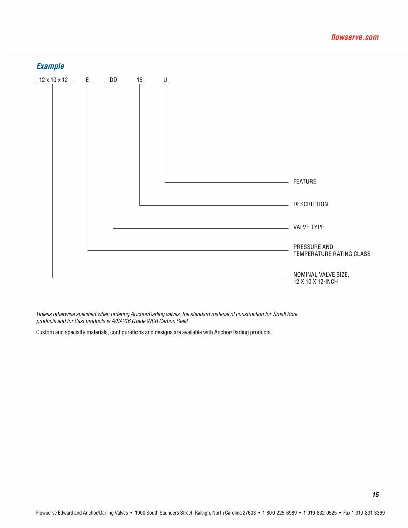
Example
Unless otherwise specified when ordering Anchor/Darling valves, the standard material of construction for Small Bore products and for Cast products is A/SA216 Grade WCB Carbon Steel.
Custom and specialty materials, configurations and designs are available with Anchor/Darling products.
E DD 15 U
FEATURE
DESCRIPTION
VALVE TYPE
PRESSURE AND TEMPERATURE RATING CLASS
12 x 10 x 12
NOMINAL VALVE SIZE, 12 X 10 X 12-INCH

16
Flowserve Edward and Anchor/Darling Valves • 1900 South Saunders Street, Raleigh, North Carolina 27603 • 1-800-225-6989 • 1-919-832-0525 • Fax 1-919-831-3369
Nuclear Safety Related ... in this critical service, you can take no chances with safety, and you can accept no compromise in quality. Flowserve’s Edward and Anchor/Darling valves don’t just meet standards – they exceed them. Our dedication to engineered quality and rigorous design standards are demonstrated by understanding and appreciating of the absolute necessity of dependability for valves installed in nuclear reactors.
Conservative Design
Flowserve’s approach to the design of safety-related valves for nuclear service is highly conservative. We meet applicable codes and standards, but go beyond those criteria employing finite element stress analysis of critical valve areas coupled with stringent proof testing. This testing and real-world installed experience have resulted in valves that exhibit very high flow efficiencies.
You will find innovative design advantages throughout the Edward and Anchor/Darling Product Lines. For example, the Edward Equiwedge gate valve features a split-wedge gate assembly that aligns perfectly into the valve’s seats by virtue of cast body guide groves; this split-wedge feature ensures leak-tight closure even if a seismic event causes racking or distortion of piping. Many of what are today termed industry standards started out as design concepts on Flowserve drawing boards.
PrecisionManufacturing
Flowserve’s Raleigh operation employs state-of-the-art six-axis machining centers that are computer controlled to
ensure repeatability, parts interchangeability and spot-on perfect dependability. Flowserve Raleigh has also developed reliable sources for castings, steel and other components that ensure continuous uninterrupted manufacturing cycles on time, within critical path shipment, of your nuclear valves and parts. Our suppliers are dedicated professionals who team with Flowserve to ensure your critical deliveries are “on the dock” on time and correct every time.
DedicatedPeople
Flowserve’s Raleigh operation employs highly skilled people dedicated to delivering the very finest and safest nuclear valves you can buy. Our engineering department is staffed with experienced senior men and women with years of practical experience working with nuclear safety-related applications in Raleigh and in the field; they bring working knowledge of the nuclear power business to your valve applications. These engineers mentor newer members of our engineering team, passing along insight and practical knowledge. Similarly, our inside sales and contract administration people bring years of practical hands-on experience to your valve requirements. They speak the language of nuclear application and will understand the intricacies of your technical inquiries.
For nuclear power plant applications, call the professionals at Flowserve’s Flow Control Division–Raleigh.
High Performance for Critical Service

flowserve.com
17
Flowserve Edward and Anchor/Darling Valves • 1900 South Saunders Street, Raleigh, North Carolina 27603 • 1-800-225-6989 • 1-919-832-0525 • Fax 1-919-831-3369
In-house computer-aided design and finite-element method capa-bilities give our engineering staff powerful tools to develop reliable valves for critical service applications. CAD-generated graphic models undergo FEM analysis to determine that stresses are within accept-able limits. Dynamic simulation of valve operation also helps ensure reliability of Flowserve Edward and Anchor/Darling valve perfor-mance.
Prototyping is just as important, and rigorous proof testing is a mainstay of Edward valve design. Before we approve a valve for production, we put it through hundreds, even thousands, of cycles to demonstrate that performance and sealing integrity will be maintained in service. Transducers relay data from test assemblies to computers for further analysis.
Laboratory simulation of critical services includes a steam generator and superheater, designed for 2700 psi and 1050°F. This flexible sys-tem allows testing of prototype valves under both low-pressure and high-pressure conditions. In addition to prototype testing, this system has been used for applications such as friction and wear tests of valve trim materials in hot water and steam environments; qualifica-tion tests of new or redesigned valves; and proof testing of new valve gaskets and valve stem packings.
Before we make the first production unit, that valve has already been through a rigorous program to ensure long life, simple maintenance and dependable performance for the lowest cost over the life of the valve. Again, people play important roles in design. The Flowserve product engineering department pools well over 400 years of valve experience.
Designed with an Eye on Your Bottom Line

18
Flowserve Edward and Anchor/Darling Valves • 1900 South Saunders Street, Raleigh, North Carolina 27603 • 1-800-225-6989 • 1-919-832-0525 • Fax 1-919-831-3369
At Flowserve Edward and Anchor/Darling Valves, quality assurance starts with meeting code requirements. Valves are manufactured to ASME section III and ANSI B16.34 (Standard, Limited and Special Classes), including standards for:
• Minimum wall thickness of valve body.
• Body, bonnet and body-bonnet bolting to specified ASME and ASTM material standards.
• Non-destructive examination requirements.
• Hydrostatic shell testing at 1.5 times the 100°F rating of the valve.
From there, Flowserve Edward and Anchor/Darling valves go on to exceed the code, with higher test standards and an additional battery of tests performed on every type of valve we make, using in-house test facilities and personnel to ensure expert quality control. Flowserve’s quality assurance program includes:
Non-DestructiveExamination
• NDE personnel are qualified in accordance with ASNT-TC-1A and EN473 requirements.
• castings are visually examined per MSS SP-55.
• The first five body castings from every pattern are 100 percent radiographed to verify casting quality.
HydrostaticTesting
• The seat-leakage criteria—no visible leakage for forged steel stop, stop-check and check valves and 2ml/hour/inch of nominal valve size for cast steel—are stricter than the allowed leakage rate of MSS SP-61, which is 10ml/hour/inch of nominal valve size for stop valves and 40ml/nr/in for stop-check and check valves.
• Seat-leakage test is performed at 110 percent of 100°F rating.
QualityControl
Requirements are clearly stated and measurements are taken to determine conformance to those requirements. “Quality” equals conformance to requirements.
Welding
Personnel and procedures are qualified in accordance with ASME Boiler and Pressure Vessel Code, Section IX and ASME Section III.
AdditionalStandardTestsforSpecificValves
Includes heavy-wall examination on large body castings.
We have listed only a few of the Flowserve Edward and Anchor/Darling valve standard tests that exceed industry requirements. In addition, Flowserve has the facilities and the expertise to meet additional quality assurance standards as required for the application.
Testing Beyond Code Requirements

flowserve.com
19
Flowserve Edward and Anchor/Darling Valves • 1900 South Saunders Street, Raleigh, North Carolina 27603 • 1-800-225-6989 • 1-919-832-0525 • Fax 1-919-831-3369
A History of FirstsFeature Benefit
Body-guided discs on globe and angle valves Minimize wear and ensure alignment for tight sealing.
Integral Stellite hardfaced seats in globe and angle valves Permit compact design and resist erosion.
Hermetically sealed globe valves with seal-welded diaphragms Prevent stem leakage in critical nuclear plant applications.
Equalizers for large check and stop-check valves Ensure full lift at moderate flow rates and prevent damage due to instability.
Compact pressure-seal bonnet joints Eliminate massive bolted flanges on large, high-pressure valves.
Qualified stored-energy actuators Allow quick-closing valves in safety-related nuclear plant applications.
Qualified valve-actuator combinations Used in main steam and feed-water service throughout the world.
Stainless steel spacer rings on gate valves, fitted between wedge halves
Simplify service. Damaged valve seats can be restored to factory fit by in-line replacement with slightly thicker ring.
Unique two-piece, flexible wedges on gate valves Automatically adjust to any angular distortion of body seats. Shape provides greater flexibility. Ensure dependable sealing and prevent sticking.
Impactor handwheels and handles Allow workers to generate several thousand foot-pounds of torque, thus ensuring tight shutoff of manually operated globe and angle valves.
Inclined-bonnet globe valves with streamlined flow passages Minimize pressure drop due to flow.
Globe valves available with both vertical and inclined stems Provide stem designs suited to any installation.
Live-loaded pressure energized PressurSeat® for globe valves Globe valve design for high-pressure drain and vent service.
Shipped first N-stamp valve Early and uninterrupted support for the nuclear industry.
First gate valve for the MSIV service Lower pressure drop and reduced actuator size.
First gas-hydraulic actuator for MSIVs Self-contained actuator independent of outside systems.
First to qualify a valve to ASME QME-1 Proven dedication to evolving industry requirements.

20
Flowserve Edward and Anchor/Darling Valves • 1900 South Saunders Street, Raleigh, North Carolina 27603 • 1-800-225-6989 • 1-919-832-0525 • Fax 1-919-831-3369
Flowserve - Edward and Anchor/Darling Valves Available for Nuclear Service
Simulated line rupture test confirms closing speed of Edward main steam isolation valve against differential pressure of 1500 psi.
The vast majority of Edward and Anchor/Darling forged and cast steel valves can be supplied for nuclear service. The following chart summarizes past Edward and Anchor/Darling valve experience by Type, Size Range and Pressure Class. Consult your Flowserve Edward valves sales representative for additional information.
ValveType Size ANSIRatings
ForgedSteelValves
Bolted Bonnet 1/2 (15) Thru 2 (50) Thru Class 600Hermavalve 1/2 (15) Thru 2-1/2 (65) Thru Class 1690
Univalve 1/2 (15) Thru 4 (100) Thru Class 2500Soft Seated Check Valve 1/2 (15) Thru 4 (100) Thru Class 2500
800 Series (Gate, Globe & Check) 1/2 (15) Thru 2 (50) Thru Class 800
1878/1888 Series (Gate, Globe & Check) 1/2 (15) Thru 2 (50) Thru Class 1878
Equiwedge Gate2-1/2 (65) - 28 (700) Thru Class 2500Flex Wedge Gate
Double-Disc GateFlite-Flow Globe
(Stop, Stop-Check & Check) 3 (80) - 32 (800) Thru Class 2500
Tilting-Disc Check 2-1/2 (65) - 24 (600)Thru Class 2500
Swing Check 2-1/2 (65) - 32 (800)In-Line Check 1 (30) Thru 2-1/2 (65) Thru Class 1500
Globe and Angle Valves (Stop, Stop Check & Check) 2-1/2 (65) - 24 (600) Thru Class 2500
Controlled Closure Check Valve (See page 113 or 191) 2-1/2 (65) - 24 (600) Thru Class 2500
Soft Seated Check Valve 2-1/2 (65) - 24 (600) Thru Class 2500Actuators(U-stamped) Stored Energy (Gas-Hydraulic) A-100 Thru A-510 and B-100 Thru B-510 Thrusts from 20,000 to over 489,000 lbs.
1/4TurnValveTop Entry Ball Valves 1/2 (15) Thru 10 (250) Thru Class 6003-Piece Ball Valves 3/4 (20) Thru 10 (250) Thru Class 300
Butterfly Valves 3 (80) Thru 20 (500) Thru Class 600
Note: See pages 5 and 10 for indicated figure numbers available for nuclear service.
EdwardandAnchor/Darlingvalvesconstructed for nuclear service can be offered for Code Class 1, 2 or 3.
CastSteel

flowserve.com
21
Flowserve Edward and Anchor/Darling Valves • 1900 South Saunders Street, Raleigh, North Carolina 27603 • 1-800-225-6989 • 1-919-832-0525 • Fax 1-919-831-3369
Flowserve Forged and Cast Steel Valves for Nuclear Service
Edward Equiwedge gate valve with an Edward gas hydraulic actuator being prepared for shipment.
Flowserve Edward and Anchor/Darling have been serving the power generation and process industries with custom engineered valves since 1888.
As a specialist with more than 100 years of experience in the production of high-specification valves for critical services, we are uniquely qualified to serve the needs of the power generation and process industries worldwide.
From the beginning of commercial nuclear power production, Flowserve valves have been used successfully in many of the most difficult applications. The Shippingport plant went on line in 1957 with special size 18" Edward stainless steel tilting disc check and and Anchor/Darling 10" double-disc gate valves in its primary coolant system. It also incorporated numerous small Edward capped manual valves. Other “first generation” commercial nuclear plants are still in operation with a broad variety of Edward and Anchor/Darling forged and cast steel valves.
Through the evolution of the pressurized water reactor (PWR), the boiling water reactor (BWR) and even the liquid metal fast breeder reactors (LMFBR), Flowserve Flow Control has been involved in meeting the most difficult challenges. This experience in engineering, manufacturing and quality assurance provides an excellent basis for supplying superior valves for nuclear service — in new construction, retrofit and life extension work.
A major Flowserve Edward Valves nuclear niche has been the main steam and feedwater isolation market (MSIVs and MFIVs). These safety-related valves must close rapidly, typically in three to five seconds, to prevent major leakage in the event of a pipe rupture. Special Edward Flite-Flow valves with air/spring actuators were used in PWRs until the Edward Equiwedge gate valve and stored energy actuator were developed in the late 1970s. Edward Equiwedge MSIVs and MFIVs with stored energy actuators are now in service on three continents—in PWRs and in steam service in an LMFBR.
Other critical nuclear applications are served by Edward check and stop-check valves, some with special features. Flowserve provides comprehensive application engineering data (see Technical Section) to support these valves, helping to avoid many of the problems that have occurred with other check valves in nuclear power plants.
In addition, thousands of small Edward forged steel valves are widely used in many nuclear plant applications that demand high reliability. Some have handwheels, some have electric motor actuators and some have pneumatic actuators, but all are designed and built to nuclear standards. Univalves and bolted bonnet valves provide excellent service in most applications, and Hermavalves are available for applications where the risk of external leakage is unacceptable.
A major manufacturer of Section III Nuclear Valves, 1/2" and larger Flowserve Edward and Anchor/Darling offer the most complete
line of valves developed for nuclear service where reliable operation, positive sealing, ease of maintenance and A.L.A.R.A. are prime considerations. Our valves are produced in the U.S.A. to an ISO 9001 certified quality program.
Flowserve Edward and Anchor/Darling small- bore valves are available to ASME Section III Class 1, 2, 3 or ANSI B16.34 requirements.
Flowserve Edward and Anchor/Darling valves are available with seating materials suitable for various applications. Where required, seat rings are firmly shouldered against the body and vacuum furnace brazed. This process gives a very precise seating surface to achieve extended service life. Seating surfaces are solid alloys that provide excellent wear and corrosion properties not possible with competitors’ integral seat designs often seen in forged valves.
Hardface materials offered as a standard include non-cobalt NOREM, cobalt-chrome Stellite and various nickel-based alloys.
Since there were 50 years of Flowserve power plant valve experience before the first nuclear plants were built, we were well prepared for the new challenges of first-generation nuclear power plants. Now, with over 50 years of nuclear valve experience, Flowserve Edward and Anchor/Darling valves are even better prepared for the challenges of the future.
Edward and Anchor/Darling valves constructed for nuclear service can be offered for Code class 1, 2 or 3.

22
Flowserve Edward and Anchor/Darling Valves • 1900 South Saunders Street, Raleigh, North Carolina 27603 • 1-800-225-6989 • 1-919-832-0525 • Fax 1-919-831-3369
Checklist of Customer Information Required for Nuclear Valve ProposalsThe following checklist is provided as a guide of important information required by the valve manufacturer to accurately quote equipment intended for nuclear service. By properly identifying this data, a more complete and specific proposal can be provided.
• Certified design specifications.
• Nuclear code class.
• Applicable codes/standards and date of issue.
• Estimated delivery requirements.
• Environmental conditions - temperature, humidity, radiation, exposure to elements.
• Piping diagrams.
• Pipe size, material, wall thickness.
• Piping forces transmitted to valve.
• Piping response spectrum to Design Basis Earthquake.
• Dimensional limitations of valve envelope.
• Physical orientation of valve - horizontal, vertical, bonnet position.
• Special materials required.
• Special buttweld end requirements.
• System design conditions - pressure, temperature.
• Normal operating conditions - pressure, temperature.
• Normal flow - pounds per hour.
• Maximum flow - pounds per hour.
• Allowable pressure drop through valve.
• Flow direction through valve.
• Active/non-active valve operational requirements - emergency opening or closing, actuation time, differential pressures and flows during operation.
• Power sources - air supply pressure (maximum and minimum) voltage supply (AC, DC), cycles, fluctuation.
• Actuator type desires.
• Safety related function.
• Qualification requirement.
Flowserve Edward Stored Energy ActuatorUnlike a safety-related motor operator, designed to open and close a valve upon being enabled by the control room, Flowserve Edward’s Gas/Hydraulic – Stored Energy Actuator is primarily designed to rapidly close a Main Steam Isolation Valve or a Main Feed Water Valve in response to a seismic event, or other containment threat. Upon activation of the actuator, in response to such an event, the com-pressed nitrogen in the hemisphere at the top of the unit immediately closes the valve in as little as two (2) seconds. The system includes a hydraulic reservoir and pump either electrically driven or pneumati-cally driven. The pump is capable of recompressing the nitrogen into the storage hemisphere to reposition the valve in the open position; simultaneously, the actuator is reset to the ready position. This same mechanism is designed to allow the valve to be exercised (partial stroked) by operators and service technicians.
The Flowserve Edward Stored Energy Actuator is built in accordance with ASME Section VIII where required and is fully certified to the applicable IEEE environmental qualification standards. These Flowserve Edward Stored Energy Actuators are in active nuclear service throughout the world.
Contact Flowserve Inc. Flow Control for a listing of U.S. and interna-tional users.
flowserve.com
23
Flowserve Edward and Anchor/Darling Valves • 1900 South Saunders Street, Raleigh, North Carolina 27603 • 1-800-225-6989 • 1-919-832-0525 • Fax 1-919-831-3369
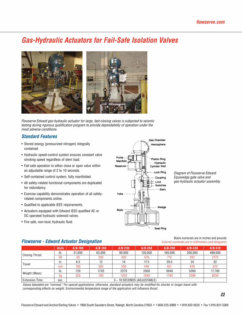
Gas-Hydraulic Actuators for Fail-Safe Isolation Valves
Flowserve Edward gas-hydraulic actuator for large, fast-closing valves is subjected to seismic testing during rigorous qualification program to provide dependability of operation under the most adverse conditions.
Standard Features• Stored energy (pressurized nitrogen) integrally
contained.
• Hydraulic speed-control system ensures constant valve stroking speed regardless of stem load.
• Fail-safe operation to either close or open valve within an adjustable range of 2 to 10 seconds.
• Self-contained control system, fully manifolded.
• All safety-related functional components are duplicated for redundancy.
• Exercise capability demonstrates operation of all safety-related components online.
• Qualified to applicable IEEE requirements.
• Actuators equipped with Edward IEEE-qualified AC or DC operated hydraulic solenoid valves.
• Fire safe, non-toxic hydraulic fluid.
Flowserve - Edward Actuator DesignationBlack numerals are in inches and pounds
Colored numerals are in millimeters and kilograms
Units A/B-100 A/B-180 A/B-230 A/B-260 A/B-290 A/B-330 A/B-510
Closing Thrustlb. 21,000 63,000 90,000 130,000 160,000 205,000 489,000kN 93 293 400 578 712 912 2175
Travelin. 6.5 12 14 17.5 20.5 24 32
mm 165 305 356 446 521 610 813
Weight (Mass)lb. 720 1720 2270 2950 3940 5260 17,700kg 325 780 1030 1340 1790 2390 8030
Extension Time sec. 3 − 10 SECONDS (ADJUSTABLE)Values tabulated are “nominal.” For special applications; otherwise, standard actuators may be modified for shorter or longer travel with corresponding effects on weight. Environmental temperature range of the application will influence thrust.
Diagram of Flowserve Edward Equiwedge gate valve and gas-hydraulic actuator assembly.

24
Flowserve Edward and Anchor/Darling Valves • 1900 South Saunders Street, Raleigh, North Carolina 27603 • 1-800-225-6989 • 1-919-832-0525 • Fax 1-919-831-3369
Since 1985, over 80% of the world’s MSIVs and MFIVs have been supplied by Flowserve!
• Simple design and operating principle
• Extensive, proven track record
• Environmentally and functionally qualified valve and actuator
• Flowserve service, training and warranty
• No failures to perform safety-related function
• Over 9,000 service years of reliable operation
Main Steam and Main Feedwater Isolation ValvesGas / Hydraulic Actuated Equiwedge Gate Valves• Single stored energy system / redundant control systems.
• Standard features include:
• Manifold-mounted hydraulic components
• Off-line testing capabilities
• Exercise stroke capabilities
• Extended periods between maintenance
• No external hose or piping connections
• Similar in weight and smaller than pneumatic actuators.
• Consistent stroke times.
• Fluid filtration systems prevent particulate contamination of hydraulic fluid.
• Environmental qualification to IEEE-382, 323 and 344.
• ASME B16.41 and QME-1 functionally qualified.

flowserve.com
25
Flowserve Edward and Anchor/Darling Valves • 1900 South Saunders Street, Raleigh, North Carolina 27603 • 1-800-225-6989 • 1-919-832-0525 • Fax 1-919-831-3369
EdwardGateValves

26
Flowserve Edward and Anchor/Darling Valves • 1900 South Saunders Street, Raleigh, North Carolina 27603 • 1-800-225-6989 • 1-919-832-0525 • Fax 1-919-831-3369
Features and Description of Flowserve Edward Equiwedge® Gate ValvesFor detailed description of the two-piece flexible wedge, see page 28.
1.Yokebushing – material has low coefficient of friction that substantially reduces torque and thread wear and eliminates galling.
2.Weather/Greaseseals – are provided to protect against environmental conditions.
3.Yoke – the yoke is designed for ready access to the packing chamber.
4.Packingandjunkring– utilizes flexible graphite packing material with anti-extrusion rings for optimum sealability and life.
5.Extendedbonnetdesign – further separates the packing chamber from fluid flow area for longer packing life. Also provides accessible area for leakoff connections if required.
6.Compositepressuresealgasket – preloaded, pressure energized design, for long, reliable service.
7.Bodyguidingsystem – holds the wedge halves together and absorbs thrust loads due to line flow. Integral hardfaced guide system components reduce friction and prevent galling for longer valve life.
8.Conicalstembackseat – Cone-on-cone design provides a reliable sealing geometry that operates over many valve cycles without leakage.
9.Body – rugged cast steel body provides maximum flow efficiency. Information on alternate materials can be obtained through your Flowserve representative.
10.Handwheel – spoke design provides more efficient transfer of load with minimum weight.
11.Taperedrollerbearings – on larger valves, tapered roller bearings reduce torque, carry the stem thrust and provide additional radial support for side loads imposed by handwheel or power actuator. Smaller size valves have needle roller bearings.
12.Stem – has ACME threads, is machined to a fine finish and is heat treated for improved strength and hardness to resist wear.
13.Packinggland – made of alloy steel, and retained against the stuffing box pressure by an easy-to-maintain stud and heavy hex nut assembly.
14. Bonnet retaining ring – ensures an effective, tight seal by pulling the bonnet and gasket together at the pressure seal.
15.Yokelockring – permits easier field maintenance of upper structure without disturbing pressure-containing parts. Valves in smaller sizes utilize a wishbone yoke design. Class 600 valves utilize a bolted pressure seal bonnet.
16.Bonnetbackseat– especially hardfaced to ensure long-term sealability.
17.Hemispherical-typebonnet – reduces valve body height and provides weight saving. Hemispherical-type design results in better pressure distribution across the bonnet area.
18.Two-piecewedgeassembly – allows each wedge half to flex and adjust independently to compensate for body distortions caused by thermal changes or pipe bending stresses. (see pg. C10)
19.Welded-inseatringwithhardfacedseat – ensures better wear and longer valve life. Seat ring is welded into the valve body to prevent leakage.
1.23.
4.
5.
6.7.
8.
9.
10.
11.
12.
13.
14.15.16.17.
18.
19.

flowserve.com
27
Flowserve Edward and Anchor/Darling Valves • 1900 South Saunders Street, Raleigh, North Carolina 27603 • 1-800-225-6989 • 1-919-832-0525 • Fax 1-919-831-3369
Description ASMENo. ASMENo. ASMENo. ASMENo.
Body/Bonnet* SA-216 Grade WCB
SA-216 Grade WCC
SA-217 Grade WC9
SA-351 Grade CF8M
Gate21/2-6 SA-732 Grade 21
SA-732 Grade 21
SA-732 Grade 21
SA-732 Grade 21
Gate8andup* SA-216 Grade WCB
SA-216 Grade WCB
SA-217 Grade WC9
SA-351 Grade CF8M
Stem A-182 Grade F6 CL4
A-182 Grade F6 CL4
A-565 Grade 616 HT
A-638 Grade 660 T2
YokeBushing B-148 Alloy 95400
B-148 Alloy 95400
B-148 Alloy 95400
B-148 Alloy 95400
PackingRings Flexible Graphite inner rings and suitable anti-extrusion rings.
JunkRings AISI 1117 MnPo4 Plated
AISI 1117 MnPo4 Plated
AISI 1117 MnPo4 Plated
A-182 Grade F316/Stellite I.D.
PressureSealGasket Composite Pressure Seal Gasket.
SpacerRing—
A-668 Grade 4140 MnPO4 Plated
— A-668 Grade 4140
MnPO4 Plated
— A-668 Grade 4140
MnPO4 Plated
— A-182
Grade F6 CL4
GasketRetainer A-182 Grade F6 CL4
A-182 Grade F6 CL4
A-565 Grade 616 HT
A-638 Grade 660 T2
BonnetRetainer A-515 Grade 70
A-515 Grade 70
A-515 Grade 70
A-515 Grade 70
BonnetRetainerStuds A-193 Grade B7
A-193 Grade B7
A-193 Grade B7
A-193 Grade B7
BonnetRetainerNuts A-194 Grade 2H
A-194 Grade 2H
A-194 Grade 2H
A-194 Grade 2H
Gland A-148 Grade 90-60
A-148 Grade 90-60
A-148 Grade 90-60
A-148 Grade 90-60/Chrome Plated
GlandStuds A-193 Grade B7
A-193 Grade B7
A-193 Grade B7
A-193 Grade B7
GlandNuts A-194 Grade 2H
A-194 Grade 2H
A-194 Grade 2H
A-194 Grade 2H
Yoke A-216 Grade WCB
A-216 Grade WCB
A-216 Grade WCB
A-216 Grade WCB
YokeLockRing A-216 Grade WCB
A-216 Grade WCB
A-216 Grade WCB
A-216 Grade WCB
YokeLockRingStuds A-193 Grade B7
A-193 Grade B7
A-193 Grade B7
A-193 Grade B7
YokeLockRingNuts A-194 Grade 2H
A-194 Grade 2H
A-194 Grade 2H
A-194 Grade 2H
Handwheel A-126 Class A
A-126 Class A
A-126 Class A
A-126 Class A
*Hardfaced wedge guide rails and seating surfaces. **Use A-368 Grade 660 T2 for applications over 1100°F
This is not a complete list. Construction and materials will vary between sizes and pressure classes and may be changed without notice. For a complete, accurate and itemized description of a particular valve, contact your Flowserve valves sales representative.
Parts Specification List for Edward Gate Valves

28
Flowserve Edward and Anchor/Darling Valves • 1900 South Saunders Street, Raleigh, North Carolina 27603 • 1-800-225-6989 • 1-919-832-0525 • Fax 1-919-831-3369
Features and Description of Flowserve Edward Equiwedge® Gate ValvesUniqueTwo-PieceFlexibleWedge
Wedging action provides tight seat sealing, even at low differential pressures. Wedge guiding by grooves in body minimizes seat wear and damage, since seating surfaces of wedge and body are in contact over less than 5% of total travel. Two separate, flexible wedge halves are free to align with seats even when they are tilted or rotated due to thermal effects or piping loads. Resistance to thermal binding ensures opening with a torque or load less than design closing load.
Wedge guide area and strength provide capability to support high differential pressures with valve partially open, so Equiwedge gate valves can be opened or closed under “blowdown” conditions. Bypasses are not required if full differential is specified for actuator sizing.
Center Cavity OverpressurizationSome valve designs are capable of sealing simultaneously against a pressure differential between an internal cavity of the valve and the adjacent pipe in both directions. Double-seated gate valves, including Equiwedge, are examples of such a design. In fact, seat joint integrity for these valves is tested in the factory by pressurizing the center cavity and simultaneously examining each seat. However, if a fluid is entrapped in such a valve while closed, and then subsequently heated, a dangerous rise in pressure can result, thus leading to pressure boundary failure.
Both ASME B16.34 (Valves - Flanged, Threaded and Welding End), para 2.3.3 and ASME B31.1 (Pressure Piping Code), para 107.1(c), recognize this situation and require that the Purchaser shall provide means in design, installation and/or operation to ensure that the pressure in the valve shall not exceed the rated pressure for the attained temperature. Therefore, if deemed necessary by the Purchaser, and so specified in the purchase order, Flowserve Edward Valves can provide an equalizer system (internal or external) that will relieve this trapped fluid to the upstream piping or a relief valve that will exhaust excessive pressure to some other specified area. It should be understood that an internal or external equalizer will change a basically bidirectional gate valve to a
Figure 1
The outstanding design feature of the Equiwedge gate valve is unique two-piece wedge that permits maximum independence and flexibility for good sealability and freedom from sticking.
Two-PieceWedge
BodyGroove
Hardfaced Wedge Guide Rails Wedge Halves
BodyHardfacedWedge Seat
Figure 2
The body groove extends high in the body neck region so that in the open position the wedge as-sembly is both trapped and fully guided. Body grooves are hard-faced for critical service valves.
Body
GuidingSystem
Body Grooves
Welded-inSeat Ring
Hardfaced Wedge Guide Rails
Figure 3
Wedge halves are separated the proper amount by a spacer ring which provides controlled deflection from stem loading. Use of a space and weight-saving “captured stem” (shown here and in Figure 4) is possible because of the two-piece wedge design.
BackFaceofWedgeHalf
Non-revolvingStem
Spacer Ring
Wedge Half
Figure 4
The Equiwedge two-piece wedge design allows the use of a space and weight-saving “captured stem.”
“CapturedStem”
Stem SeatingShoulder
StemBackseat
Wedge Half Wedge Half
design with fully effective seat sealing in only one direction. The equalizer bypasses the upstream seat and would allow leakage by that seat if the pressure should be reversed. The “downstream” seat would become the “upstream” seat with pressure reversed; the wedging action provided by stem load provides good upstream seat sealing at low to moderate pressures, but leakage could be excessive at high pressures.
Excessive pressure trapped in the center cavity of a gate valve can also produce
“pressure locking”—a condition that can make opening difficult or impossible. Either an internal or an external equalizer will prevent pressure locking. However, a relief valve may allow the center cavity pressure to be higher than either the upstream or downstream pressure, and this can allow pressure locking to occur. The Flowserve Edward valves’ unique ACCEV (Automation Center Cavity Equalizing Valve) can alleviate this problem. Refer to page 197 for additional information.

flowserve.com
29
Flowserve Edward and Anchor/Darling Valves • 1900 South Saunders Street, Raleigh, North Carolina 27603 • 1-800-225-6989 • 1-919-832-0525 • Fax 1-919-831-3369
Equiwedge Stop Valves, Class 600
Standard Features• Bodies and bonnets are cast steel
(WCB, WCC, WC9, CF8M)
• Pressure-seal bonnet OS & Y
• Integral Stellite seats and backseat
• Two-piece body-guided wedge
• 13% chromium stainless steel stem
• Asbestos-free graphitic packing
• Composite pressure-seal gasket
• Available in standard or venturi pattern
• Yoke bushing thrust bearings
Pressure Class 600 (PN 110)Fig. No.
Type Ends Bonnet NPS(DN)STDCL SPLCL
1611* — Equiwedge Gate Flanged Pressure Seal21/2 (65) thru 28 (700)
1611Y 1711Y Equiwedge Gate Butt Weld Pressure Seal
1611BY 1711BYVenturi Pattern
Butt Weld Pressure Seal 8 (200) thru 32 (800)Equiwedge Gate
* Flanges to size 24 only.
Dimensions – Equiwedge GateBlack numerals are in inches and pounds
Colored numerals are in millimeters and kilograms
FigureNo.1611/1611Y,1711YNPS 21/2 3 4 6 8 10 12 14DN 65 80 100 150 200 250 300 350
A - End to End (Welding)10 10 12 18 23 28 32 35
254 254 305 457 584 711 813 889
C - Face to Face (Flanged)13 14 17 22 26 31 33 35
330 356 432 559 660 787 838 889
E - Center to Top, (Open)22.25 22.25 25.5 31.75 39.75 48 54 58.5565 565 648 806 1010 1219 1372 1486
G - Handwheel Diameter14 14 14 24 24 30 30 36
356 356 356 610 610 762 762 914
Weight (Welding)81 81 175 372 667 1050 1623 234537 37 79 169 303 476 738 1066
* E, G, and other dimensions and information supplied upon request. Refer to page 27 for materials of construction. Refer to pages 203 through 238 for the applicable pressure ratings.
1611Y

30
Flowserve Edward and Anchor/Darling Valves • 1900 South Saunders Street, Raleigh, North Carolina 27603 • 1-800-225-6989 • 1-919-832-0525 • Fax 1-919-831-3369
Equiwedge Stop Valves, Class 600
Dimensions – Equiwedge Gate Venturi Pattern
Black numerals are in inches and poundsColored numerals are in millimeters and kilograms
Figure No. 1611BY, 1711BYNPS 8x6x8 10x8x10 12x10x12 14x12x14 16x14x16 18x16x18DN 200 250 300 350 400 450
A - End to End (Welding)18 23 28 32 35 39
457 584 711 813 889 991
E - Center to Top, (Open)31.75 39.75 48 54 58.5 67806 1010 1219 1372 1486 1702
G - Handwheel Diameter24 24 30 30 36 36610 610 762 762 914 914
Weight (Welding)372 610 1114 1623 2345 2950169 277 506 738 1066 1338
Figure No. 1611BY, 1711BYNPS 20x18x20 22x20x22 24x20x24 26x22x26 28x24x28 30x26x30 32x28x32DN 500 550 600 650 700 750 800
A - End to End (Welding)43 47 47 51 55 57 61
1092 1194 1194 1295 1397 1448 1549
E - Center to Top, (Open)76 82.75 82.75 89 96 101 110.5
1930 2102 2102 2261 2438 2565 2807
G - Handwheel Diameter36 36 48 48 48 48 48914 914 1219 1219 1219 1219 1219
Weight (Welding)3600 5000 5700 6500 7000 8500 10,5001633 2268 2585 2948 3175 3855 4762
Refer to page 27 for materials of construction. Refer to pages 203 through 238 for the applicable pressure ratings.
Dimensions – Equiwedge Gate (continued) Black numerals are in inches and poundsColored numerals are in millimeters and kilograms
FigureNo.1611/1611Y,1711YNPS 16 18 20 22 24 26 28DN 400 450 500 550 600 650 700
A - End to End (Welding)39 43 47 51 55 57 61
991 1092 1194 1295 1397 1448 1549
C - Face to Face (Flanged)39 43 47 51 55 57 61
991 1092 1194 1295 1397 1448 1549
E - Center to Top, (Open)67 76 82.75 89 96 101 110.5
1702 1930 2102 2261 2438 2565 2807
G - Handwheel Diameter36 36 36 48 48 48 48914 914 914 1219 1219 1219 1219
Weight (Welding)2950 3600 5000 5700 6500 8000 10,0001338 1633 2268 2585 2948 3628 4535
* E, G and other dimensions and information supplied upon request.

flowserve.com
31
Flowserve Edward and Anchor/Darling Valves • 1900 South Saunders Street, Raleigh, North Carolina 27603 • 1-800-225-6989 • 1-919-832-0525 • Fax 1-919-831-3369
Equiwedge Stop Valves, Class 900
Standard Features• Bodies and bonnets are cast steel
(WCB, WCC, WC9, CF8M)
• Pressure-seal bonnet, OS and Y
• Integral Stellite seat, disc and backseat
• Two-piece body-guided wedge
• 13% chromium stainless steel stem
• Asbestos-free graphitic packing
• Available in standard or venturi pattern
• Yoke bushing thrust bearings
• Composite pressure seal gasket
Pressure Class 900 (PN 150)Fig. No.
Type Ends Bonnet NPS(DN)STDCL SPLCL
1911 — Equiwedge Gate Flanged Pressure-Seal21/2 (65) thru 28 (700)
1911Y 14311Y Equiwedge Gate Butt Weld Pressure-Seal
1911BY 14311BY Venturi Pattern Equiwedge Gate Butt Weld Pressure-Seal 8 (200) thru 32 (800)
Dimensions – Equiwedge GateBlack numerals are in inches and pounds
Colored numerals are in millimeters and kilograms
FigureNo.1911/1911Y,14311YNPS 21/2 3 4 6 8 10 12 14DN 65 80 100 150 200 250 300 350
A - End to End (Welding)12 12 14 20 26 31 36 39
305 305 356 508 660 787 914 991
C - Face to Face (Flanged)16.5 15 18 24 29 33 38 40.5419 381 457 610 737 838 965 1029
E - Center to Top (Open)21.25 21.25 24.5 33.5 40 46.75 54.5 59540 540 622 851 1016 1187 1384 1499
G - Handwheel Diameter14 14 18 24 24 36 36 36
356 356 457 610 610 914 914 914
Weight (Welding)95 125 165 380 690 1523 2118 280543 57 75 172 313 692 963 1275
Refer to page 27 for materials of construction. Refer to pages 203 through 238 for the applicable pressure ratings.

32
Flowserve Edward and Anchor/Darling Valves • 1900 South Saunders Street, Raleigh, North Carolina 27603 • 1-800-225-6989 • 1-919-832-0525 • Fax 1-919-831-3369
Equiwedge Stop Valves, Class 900
Dimensions – Equiwedge Gate Venturi Pattern
Black numerals are in inches and poundsColored numerals are in millimeters and kilograms
Figure No. 1911BY, 14311BYNPS 8x6x8 10x8x10 12x10x12 14x12x14 16x14x16 18x16x18DN 200 250 300 350 400 450
A - End to End (Welding)20 26 31 36 39 43
508 660 787 914 991 1092
E - Center to Top (Open)33.5 40 46.75 54.5 59 68851 1016 1187 1384 1499 1727
G - Handwheel Diameter24 24 36 36 36 36610 610 914 914 914 914
Weight (Welding)530 891 1523 2118 2805 4150241 405 692 963 1275 1882
Figure No. 1911BY, 14311BYNPS 20x18x20 22x20x22 24x20x24 26x22x26 28x24x28 30x26x30 32x28x32DN 500 550 600 650 700 750 800
A - End to End (Welding)48 52 52 57 61 64 68
1219 1321 1321 1448 1549 1626 1727
E - Center to Top (Open)73.75 82 82 89.25 95 102 1091873 2083 2083 2267 2413 2591 2769
G - Handwheel Diameter36 48 48 48 48 60 60914 1219 1219 1219 1219 1524 1524
Weight (Welding)4500 6970 7200 8000 10,000 12,500 15,0002041 3162 3266 3629 4536 5670 6804
Refer to page 27 for materials of construction. Refer to pages 203 through 238 for the applicable pressure ratings.
Dimensions – Equiwedge Gate (continued) Black numerals are in inches and poundsColored numerals are in millimeters and kilograms
FigureNo.1911/1911Y,14311YNPS 16 18 20 22 24 26 28DN 400 450 500 550 600 650 700
A - End to End (Welding)43 48 52 57 61 64 68
1092 1291 1321 1448 1549 1626 1727
C - Face to Face (Flanged)44.5 48 52 57 61
Available Upon Request1130 1291 1321 1448 1549
E - Center to Top (Open)68 73.75 82 89.25 95 102 109
1727 1873 2083 2267 2413 2591 2769
G - Handwheel Diameter36 36 48 48 48 60 60914 914 1219 1219 1219 1524 1524
Weight (Welding)4150 4300 5800 7500 9600 12,0001882 1950 2631 3402 4355 5443

flowserve.com
33
Flowserve Edward and Anchor/Darling Valves • 1900 South Saunders Street, Raleigh, North Carolina 27603 • 1-800-225-6989 • 1-919-832-0525 • Fax 1-919-831-3369
Equiwedge Stop Valves, Class 1500
Standard Features• Bodies and bonnets are cast steel
(WCB, WCC, WC9, CF8M)
• Pressure-seal bonnet, OS & Y
• Integral Stellite seats and backseat
• Two-piece body-guided wedge
• 13% chromium stainless steel stem
• Asbestos-free graphitic packing
• Available in standard or venturi pattern
• Yoke bushing thrust bearings
Pressure Class 1500 (PN 260)Fig. No.
Type Ends NPS(DN)STDCL SPLCL
11511 — Equiwedge Gate Flanged*21/2 (65) thru 24 (600)
11511Y 12011Y Equiwedge Gate Butt Weld
11511BY 12011BY Venturi Pattern Equiwedge Gate Butt Weld 8 (200) thru 28 (700)
* Optional weld-on flanges.
Dimensions – Equiwedge GateBlack numerals are in inches and pounds
Colored numerals are in millimeters and kilograms
FigureNo.11511/11511Y,12011YNPS 21/2 3 4 6 8 10 12DN 65 80 100 150 200 250 300
A - End to End (Welding)12 12 16 22 28 34 39
305 305 406 559 711 864 991
C - Face to Face (Flanged)16.5 18.5 21.5 27.75 32.75 39 44.5419 470 546 705 832 991 1130
E - Center to Top (Open)21.25 21.25 24.25 31.5 40 48.25 55.25540 540 616 800 1016 1226 1403
G - Handwheel Diameter14 14 18 24 36 36 36
356 356 457 610 914 914 914
Weight (Welding)125 125 190 490 675 1730 272557 57 86 222 306 785 1236
FigureNo.11511/11511Y,12011YNPS 14 16 18 20 22 24DN 350 400 450 500 550 600
A - End to End (Welding)42 47 53 58 67 76.5
1067 1194 1346 1473 1702 1943
C - Face to Face (Flanged)49.5 54.5 60.5 65.5 71 76.51257 1384 1537 1664 1803 1943
E - Center to Top (Open)61 68.75 73.75 80 86.75 93.5
1549 1746 1873 2032 2203 2375
G - Handwheel Diameter48 48 48 60 60 60
1219 1219 1219 1524 1524 1524
Weight (Welding)3660 4450 6000 8000 10,500 13,0001660 2019 2722 3629 4763 5897
Refer to page 27 for materials of construction. Refer to pages 203 through 238 for the applicable pressure ratings.
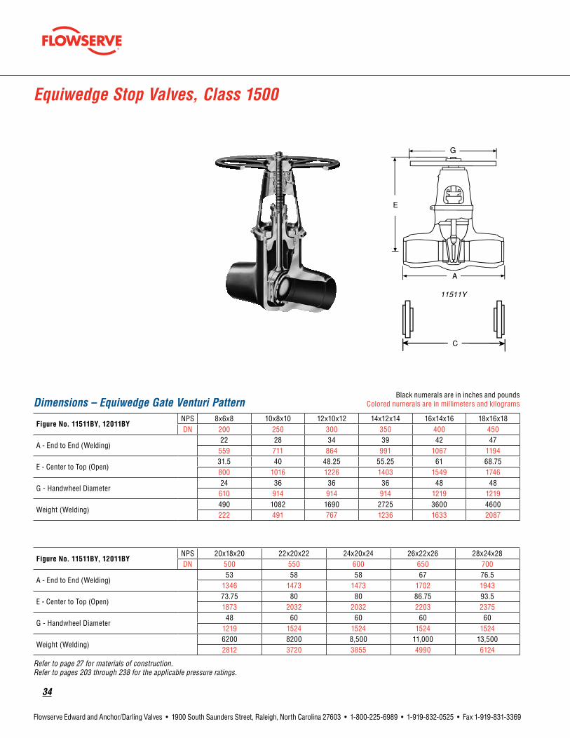
34
Flowserve Edward and Anchor/Darling Valves • 1900 South Saunders Street, Raleigh, North Carolina 27603 • 1-800-225-6989 • 1-919-832-0525 • Fax 1-919-831-3369
Equiwedge Stop Valves, Class 1500
Dimensions – Equiwedge Gate Venturi PatternBlack numerals are in inches and pounds
Colored numerals are in millimeters and kilograms
FigureNo.11511BY,12011BYNPS 8x6x8 10x8x10 12x10x12 14x12x14 16x14x16 18x16x18DN 200 250 300 350 400 450
A - End to End (Welding)22 28 34 39 42 47
559 711 864 991 1067 1194
E - Center to Top (Open)31.5 40 48.25 55.25 61 68.75800 1016 1226 1403 1549 1746
G - Handwheel Diameter24 36 36 36 48 48610 914 914 914 1219 1219
Weight (Welding)490 1082 1690 2725 3600 4600222 491 767 1236 1633 2087
FigureNo.11511BY,12011BYNPS 20x18x20 22x20x22 24x20x24 26x22x26 28x24x28DN 500 550 600 650 700
A - End to End (Welding)53 58 58 67 76.5
1346 1473 1473 1702 1943
E - Center to Top (Open)73.75 80 80 86.75 93.51873 2032 2032 2203 2375
G - Handwheel Diameter48 60 60 60 60
1219 1524 1524 1524 1524
Weight (Welding)6200 8200 8,500 11,000 13,5002812 3720 3855 4990 6124
Refer to page 27 for materials of construction. Refer to pages 203 through 238 for the applicable pressure ratings.

flowserve.com
35
Flowserve Edward and Anchor/Darling Valves • 1900 South Saunders Street, Raleigh, North Carolina 27603 • 1-800-225-6989 • 1-919-832-0525 • Fax 1-919-831-3369
Anchor/DarlingGateValves

36
Flowserve Edward and Anchor/Darling Valves • 1900 South Saunders Street, Raleigh, North Carolina 27603 • 1-800-225-6989 • 1-919-832-0525 • Fax 1-919-831-3369
Features and Description of Anchor/Darling 800 Series Gate Valves
1.Oversizedstem provides stronger disc-to-stem connection and reduces packing wear through increased stiffness.
2.Graphitestem packing provides better sealing and longer packing life.
3.ADVansealpressure sealing system eliminates leakage, reduces maintenance and is more cost effective.
4.Seatring is solid, hardened material (Stellite or non-Cobalt) and is fully shouldered and brazed in place.
5.Twopiecesplitwedge is body guided, self aligning and solid, hardened material (Stellite or non-Cobalt).
6.Machinedbackseat provides additional packing protection.
7.Investmentcastbody produces a smooth flow transition, minimizes flow turbulence resulting in higher Cv’s. Pressure seal bonnet eliminates leakage.
1.
2.
3.
4.
6.
7.
5.

flowserve.com
37
Flowserve Edward and Anchor/Darling Valves • 1900 South Saunders Street, Raleigh, North Carolina 27603 • 1-800-225-6989 • 1-919-832-0525 • Fax 1-919-831-3369
Parts Specification List for Anchor/Darling 800 Series Gate ValvesStandard Features• Available body material
SA216-WCB SA351-CF8M
• Investment cast for smooth flow
• Rising stem design
Anchor/Darling800SeriesgatevalvesfornuclearservicearenormallyfurnishedinClass800.Otherinterpolatedpressureclasses are also available on application.
Parts shown are not applicable to all 800 Series valves. Construction and materials for nuclear valves may vary depending upon customer design specifications. For a complete, accurate and itemized description of a particular valve, contact your local Flowserve valves sales representative.
Description ASME/ASTMNo. ASME/ASTMNo.Body SA216-WCB SA351-CF8MBonnet SA479-316 SA479-316Stem A564-630-1075 A564-630-1075Disc SA564-XM13-1100 SA564-XM13-1100Seat NOREM or Stellite NOREM or StelliteEndRings Braided Graphite Braided GraphitePackingRings Grafoil GrafoilGlandRetainer A564-630-1075 A564-630-1075GlandAdjustingScrew AISI-300 AISI-300GlandFlange A479-316 A479-316Yoke A351-CF8M A351-CF8MYokeSleeve B21-C464-H02 B21-C464-H02YokeBolt A193-B7 A193-B7YokeBoltNut A194-2H A194-2HHandwheel A351-CF8M A351-CF8MHandwheelNut Carbon Steel Carbon SteelGasketRetainer SA564-630-1075 SA564-630-1075

38
Flowserve Edward and Anchor/Darling Valves • 1900 South Saunders Street, Raleigh, North Carolina 27603 • 1-800-225-6989 • 1-919-832-0525 • Fax 1-919-831-3369
800 Series Stop Valves, Class 800
Features• Pressure Class 800 (Intermediate)
(WCB, CF8M)
• Investment cast body
• Split wedge, body-guided disc
• Non-cobalt seat rings; standard
• Oversized non-rotating stem
• ADVanseal® pressure seal
• Graphite stem packing
• Machined backseat
Pressure Class 800 (PN 130)Fig. No. Type Ends NPS(DN)
USW90S Gate Socket Weld 1/2 (15) thru 2 (50)
USW90U Gate Butt Weld 1/2 (15) thru 2 (50)
Dimensions – GateBlack numerals are in inches and pounds
Colored numerals are in millimeters and kilograms
FigureNo.USW90S/USW90UNPS 1/2 3/4 1 11/2 2DN 15 20 25 40 50
A3.3 3.6 4.5 4.8 5.184 91 114 122 130
D3.0 3.0 4.0 6.0 6.076 76 102 152 152
F5.7 5.7 6.9 8.5 9.8145 145 175 216 249
G6.3 6.3 7.7 10.0 11.4160 160 196 254 290
Weight Approx (lbs.)4.3 4.5 7.5 14.5 18.52.0 2.0 3.4 6.6 8.4
Cv 15 28 50 120 175
Refer to page 37 for materials of construction. Refer to pages 203 through 238 for the applicable pressure ratings.
D
F
A
G

flowserve.com
39
Flowserve Edward and Anchor/Darling Valves • 1900 South Saunders Street, Raleigh, North Carolina 27603 • 1-800-225-6989 • 1-919-832-0525 • Fax 1-919-831-3369
1.
2.
3.
4.
5.
6.
NEED PDF: Anchor/Darling Double Disc Gate Valves.pdf
1. Conversion from manual to motor-actuated valve does not require stem or bonnet change. Simply remove T-handle assembly and replace yoke.
2.Stainlesssteelyoke provides a non-corroding protector for the stem and gland area in the harshest environments
3.Pressuresealbonnetdesign allows easy access to valve internals while keeping radiation exposure to a minimum. A formed graphite gasket creates an extremely tight fit between the body and bonnet, while enhanced flexibility
and uniformity prohibit unacceptable body-to-bonnet leakage caused by minor marring in seal surfaces. Lower cost, easier reassembly, improved longevity and proven service in high-pressure nuclear and fossil generating-applications.
4.T-Headdesign stem provides positive backseat sealing.
5.Rugged,lowprofile, one-piece body with high Cv values and low center of gravity is designed to avoid distortion of internal parts due to piping loads and stresses.
6. Discs with uniform hardness and ample reserve margin for lapping or machining, resulting in greater integrity and longevity.Discs are flat; no critical angle to maintain or restore. Discs are trunion mounted and rotate during operation, resulting in even wear. Flat surfaces means no critical angle to maintain or restore.
Features and Description of 1888 Series Double-Disc Gate Valve

40
Flowserve Edward and Anchor/Darling Valves • 1900 South Saunders Street, Raleigh, North Carolina 27603 • 1-800-225-6989 • 1-919-832-0525 • Fax 1-919-831-3369
Parts Specification List for Anchor/Darling 1888 Series Double-Disc Gate ValvesStandard Features• Available body material
SA216-WCB SA351-CF8M
• Investment cast for smooth flow
• Rising stem design
Anchor/Darling1888SeriesgatevalvesfornuclearservicearenormallyfurnishedinClass 1888. Other interpolated pressure classes are also available on application.
Parts shown are not applicable to all 1888 Series valves. Construction and materials for nuclear valves may vary depending upon customer design specifications. For a complete, accurate and itemized description of a particular valve, contact your local Flowserve valves sales representative.
Description ASME/ASTMNo. ASME/ASTMNo.Body SA216-WCB SA351-CF8MBonnet SA105 SA182-F316Stem A564-630-1075 A564-630-1075Disc NOREM NOREMBodySeat NOREM NOREMEndRings Braided Graphite Braided GraphitePackingRings Grafoil GrafoilGland A351-CF8M A351-CF8MGlandBolts A193-B7 A564-630-1100Yoke A351-CF8M A351-CF8MYokeSleeve B21-C464-H02 B21-C464-H02YokeBolt A574 A574YokeBoltNut A194-2H A194-2HHandle A351-CF8M A351-CF8MStemNut AISI 316 AISI 316

flowserve.com
41
Flowserve Edward and Anchor/Darling Valves • 1900 South Saunders Street, Raleigh, North Carolina 27603 • 1-800-225-6989 • 1-919-832-0525 • Fax 1-919-831-3369
Series 1888 Stop Valves, Class 1888
Features• Pressure Class 1888 (Intermediate)
(WCB, CF8M)
• Ease of maintenance
• Uniform seat wear
• Rapid closure
• Critical surfaces hardened with non-cobalt materials
• Versatile actuator application
• No critical angles to maintain
Dimensions – GateBlack numerals are in inches and pounds
Colored numerals are in millimeters and kilograms
FigureNo.TDD15S/TDD15UNPS 3/4 1 11/4 11/2 2DN 20 25 30 40 50
A4.5 4.5 4.5 5.3 5.3114 114 114 135 135
B12.7 12.7 12.7 12.9 12.9323 323 323 328 328
C14.1 14.1 14.1 14.8 14.8358 358 358 376 376
H10.0 10.0 10.0 10.0 10.0254 254 254 254 254
Weight Approx (lbs.)27 27 27 36 36
12.2 12.2 12.2 16.3 16.3Cv 27 51 35 135 82
Refer to page 40 for materials of construction. Refer to pages 203 through 238 for the applicable pressure ratings.
Pressure Class 1888 (PN 325)Fig. No. Type Ends NPS(DN)
TDD15S Double-disc Gate Socket Weld 3/4 (20) thru 2 (50)
TDD15U Double-disc Gate Butt Weld 3/4 (20) thru 2 (50)
Double-Disc OptionDisc Pack, Exploded View
Parallel Slide OptionDisc Pack
BC
H
A
D

42
Flowserve Edward and Anchor/Darling Valves • 1900 South Saunders Street, Raleigh, North Carolina 27603 • 1-800-225-6989 • 1-919-832-0525 • Fax 1-919-831-3369
• Uniform Seat Wear
• Low-Pressure Sealing
• Between-Seat Sealing
• Reliable Operation
• Versatile Actuator Application
• Critical Surfaces Hardfaced for Long Wear
• Rapid Closure
• Ease of Maintenance
Features and Description of Anchor/Darling Double-Disc Gate Valves
Flowserve Anchor/Darling double-disc gate valves have been designed to provide reliable operation under the most severe service conditions.
This unique design will provide reliable operation when subjected to large pipe
nozzle loadings, rapid closure and repeated cycling. Extreme temperatures, gross thermal transients, high and low differential pressures, dirty and dual phase fluids have been considered in the development of the double-disc gate valve design.
Flowserve regularly supplies valves from 1/2" to 54" in diameter and 150 to 4500 psi pressure ratings in carbon steel and a wide range of special alloys. Seating surfaces are normally Stellite but other materials can be supplied depending on the application.
Reliable Under the Toughest Conditions
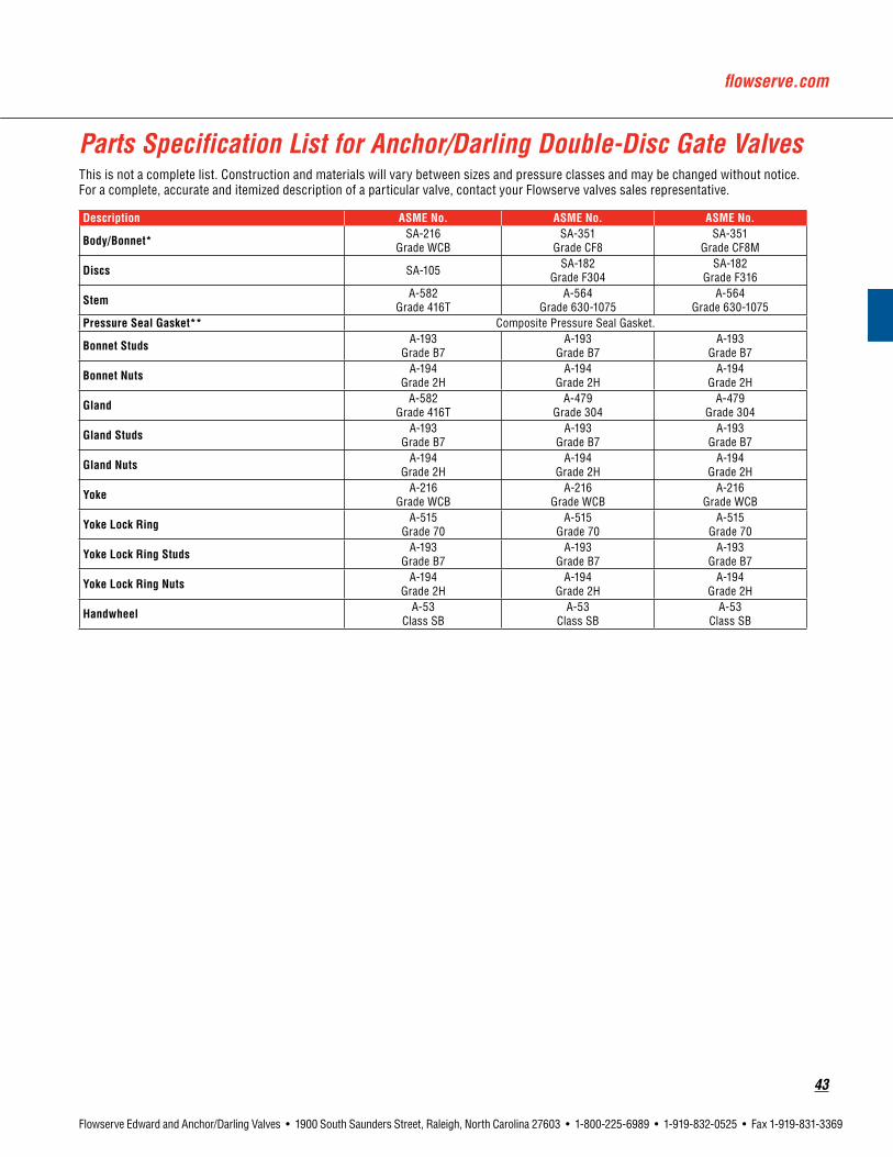
flowserve.com
43
Flowserve Edward and Anchor/Darling Valves • 1900 South Saunders Street, Raleigh, North Carolina 27603 • 1-800-225-6989 • 1-919-832-0525 • Fax 1-919-831-3369
Description ASMENo. ASMENo. ASMENo.
Body/Bonnet* SA-216 Grade WCB
SA-351 Grade CF8
SA-351 Grade CF8M
Discs SA-105 SA-182 Grade F304
SA-182 Grade F316
Stem A-582 Grade 416T
A-564 Grade 630-1075
A-564 Grade 630-1075
PressureSealGasket** Composite Pressure Seal Gasket.
BonnetStuds A-193 Grade B7
A-193 Grade B7
A-193 Grade B7
Bonnet Nuts A-194 Grade 2H
A-194 Grade 2H
A-194 Grade 2H
Gland A-582 Grade 416T
A-479 Grade 304
A-479 Grade 304
GlandStuds A-193 Grade B7
A-193 Grade B7
A-193 Grade B7
GlandNuts A-194 Grade 2H
A-194 Grade 2H
A-194 Grade 2H
Yoke A-216 Grade WCB
A-216 Grade WCB
A-216 Grade WCB
YokeLockRing A-515 Grade 70
A-515 Grade 70
A-515 Grade 70
YokeLockRingStuds A-193 Grade B7
A-193 Grade B7
A-193 Grade B7
YokeLockRingNuts A-194 Grade 2H
A-194 Grade 2H
A-194 Grade 2H
Handwheel A-53 Class SB
A-53 Class SB
A-53 Class SB
This is not a complete list. Construction and materials will vary between sizes and pressure classes and may be changed without notice. For a complete, accurate and itemized description of a particular valve, contact your Flowserve valves sales representative.
Parts Specification List for Anchor/Darling Double-Disc Gate Valves

44
Flowserve Edward and Anchor/Darling Valves • 1900 South Saunders Street, Raleigh, North Carolina 27603 • 1-800-225-6989 • 1-919-832-0525 • Fax 1-919-831-3369
Dimensions – Double-DiscBlack numerals are in inches and pounds
Colored numerals are in millimeters and kilograms
Figure No. BDD10U/BDD10C
NPS 21/2 3 4 6 8 10 12 14 16 18 20 24DN 65 80 100 150 200 250 300 350 400 450 500 600
B9.5 11.1 12.0 15.9 16.5 18.0 19.8 22.5 24.0 26.0 28.0 32.0241 282 305 404 419 457 503 572 610 660 711 813
D23.0 25.0 31.0 41.0 46.0 54.0 63.0 67.0 74.0 81.0 90.0 104.0584 635 787 1,041 1,168 1,372 1,600 1,702 1,880 2,057 2,286 2,642
E8.0 10.0 10.0 14.0 20.0 12.0 12.0 12.0 12.0 18.0 18.0 18.0203 254 254 356 508 305 305 305 305 457 457 457
Weight Approx (lbs.)100 195 300 450 665 895 975 1350 1640 1930 2350 298545.4 88.4 136.1 204.1 301.6 406 442.3 612.4 743.9 875.4 1,066 1,354
Cv 375 550 1025 2425 4500 7150 10,425 12,925 17,375 22,450 28,225 41,725
Refer to page 43 for materials of construction. Refer to pages 203 through 238 for the applicable pressure ratings.
Features• Carbon, stainless or special alloys
• Bolted bonnet
• Available Stellite seat, disc and backseat
• Seat-guided disc
• Various combinations of seat and stem material
• Uniform distribution of sealing pressure
Pressure Class 150 (PN 25)Fig. No. Type Ends NPS(DN)
BDD10U Double-disc Gate Butt Weld 21/2 (65) thru 24 (600)
BDD10C Double-disc Gate Flanged 21/2 (65) thru 24 (600)
Double-Disc Stop Valves, Class 150
B
E
D

flowserve.com
45
Flowserve Edward and Anchor/Darling Valves • 1900 South Saunders Street, Raleigh, North Carolina 27603 • 1-800-225-6989 • 1-919-832-0525 • Fax 1-919-831-3369
Dimensions – Double-DiscBlack numerals are in inches and pounds
Colored numerals are in millimeters and kilograms
FigureNo.CDD10U/CDD10CNPS 21/2 3 4 6 8 10 12 14 16 18 20 24DN 65 80 100 150 200 250 300 350 400 450 500 600
B9.5 11.1 12 15.9 16.5 18 19.8 30 33 36 39 45241 282 305 404 419 457 503 762 838 914 991 1,143
D24 26 32 41 51 58 66 70 76 83 94 105610 660 813 1,041 1,295 1,473 1,676 1,778 1,930 2,108 2,388 2,667
E8 10 12 20 12 12 12 12 12 18 18 18
203 254 305 508 305 305 305 305 305 457 457 457
Weight Approx (lbs.)100 195 300 450 800 1,055 1,260 1,550 2,150 2,890 3,350 5,58045.4 88.5 136.1 204.1 362.9 478.5 571.5 703.1 975.2 1,310.9 1,519.6 2,531.1
Cv 375 550 1,025 2,425 4,500 7,150 10,425 12,925 17,375 21,800 27,500 40,825
Refer to page 43 for materials of construction. Refer to pages 203 through 238 for the applicable pressure ratings.
Double-Disc Stop Valves, Class 300
Standard Features• Carbon, stainless or special alloys
• Bolted bonnet
• Available Stellite seat, disc and backseat
• Seat-guided disc
• Various combinations of seat and stem material
• Uniform distribution of sealing pressure
Pressure Class 300 (PN 50)Fig. No. Type Ends NPS(DN)
CDD10U Double-disc Gate Butt Weld 21/2 (65) thru 24 (600)
CDD10C Double-disc Gate Flanged 21/2 (65) thru 24 (600)
B
D
E

46
Flowserve Edward and Anchor/Darling Valves • 1900 South Saunders Street, Raleigh, North Carolina 27603 • 1-800-225-6989 • 1-919-832-0525 • Fax 1-919-831-3369
B
D
E
Dimensions – Double-DiscBlack numerals are in inches and pounds
Colored numerals are in millimeters and kilograms
FigureNo.EDD10U/EDD10C, EDD15U/EDD15C
NPS 21/2 3 4 6 8 10 12 14 16 18 20 24DN 65 80 100 150 200 250 300 350 400 450 500 600
B8.5 10 12 18 23 28 32 35 39 43 47 55216 254 305 457 584 711 813 889 991 1,092 1,194 1,397
D22 27 33 42 51 57 68 72 79 87 99 111
559 686 838 1,067 1,295 1,448 1,729 1,829 2,007 2,210 2,515 2,819
E10 12 14 20 12 12 12 12 18 18 18 24
245 305 356 508 305 305 305 305 457 457 457 610
Weight Approx (lbs.)85 140 225 450 940 1,185 1,575 2,160 2,795 3,525 5,575 7,750
38.6 63.5 102.0 204.1 426.4 537.5 714.4 979.8 1,267.8 1,599.0 2,528.8 3,515.4Cv 375 550 1,025 2,375 4,225 6,625 9,850 12,025 15,900 20,100 24,900 36,525
Refer to page 43 for materials of construction. Refer to pages 203 through 238 for the applicable pressure ratings.
Double-Disc Stop Valves, Class 600
Standard Features• Carbon, stainless or special alloys
• Bolted bonnet or pressure seal
• Available Stellite seat, disc and backseat
• Seat-guided disc
• Various combinations of seat and stem material
• Uniform distribution of sealing pressure
Pressure Class 600 (PN 110)Fig. No. Bonnet Type Ends NPS(DN)
EDD10U Bolted Bonnet Double-disc Gate Butt Weld 21/2 (65) thru 24 (600)
EDD10C Bolted Bonnet Double-disc Gate Flanged 21/2 (65) thru 24 (600)
EDD15U Pressure Seal Double-disc Gate Butt Weld 21/2 (65) thru 24 (600)
EDD15C Pressure Seal Double-disc Gate Flanged 21/2 (65) thru 24 (600)

flowserve.com
47
Flowserve Edward and Anchor/Darling Valves • 1900 South Saunders Street, Raleigh, North Carolina 27603 • 1-800-225-6989 • 1-919-832-0525 • Fax 1-919-831-3369
Dimensions – Double-DiscBlack numerals are in inches and pounds
Colored numerals are in millimeters and kilograms
FigureNo.FDD15U/FDD15CNPS 21/2 3 4 6 8 10 12 14 16 18 20 24DN 65 80 100 150 200 250 300 350 400 450 500 600
B10 12 14 20 26 31 36 39 43 48 50 59
254 305 356 508 660 787 914 991 1,092 1,219 1,270 1,499
D26 28 33 43 52 61 67 73 84 91 101 115
660 711 838 1,092 1,321 1,549 1,702 1,854 2,134 2,311 2,565 2,921
E12 14 16 12 12 12 12 18 18 18 18 24
305 356 406 305 305 305 305 457 457 457 457 610
Weight Approx (lbs.)130 175 260 690 1,065 1,375 2,085 2,560 3,335 4,650 6,265 9,80059 79.4 117.9 313 492.1 623.7 945.8 1,161 1,513 2,109 2,842 4,445
Cv 300 500 950 2,175 3,825 6,125 8,850 10,875 14,325 18,300 22,875 33,275
Refer to page 43 for materials of construction. Refer to pages 203 through 238 for the applicable pressure ratings.
Double-Disc Stop Valves, Class 900
Standard Features• Carbon, stainless or special alloys
• Pressure seal
• Available Stellite seat, disc and backseat
• Seat-guided disc
• Various combinations of seat and stem material
• Uniform distribution of sealing pressure
Pressure Class 900 (PN 150)Fig. No. Type Ends NPS(DN)
FDD15U Double-disc Gate Butt Weld 21/2 (65) thru 24 (600)
FDD15C Double-disc Gate Flanged 21/2 (65) thru 24 (600)
G
E
D
B

48
Flowserve Edward and Anchor/Darling Valves • 1900 South Saunders Street, Raleigh, North Carolina 27603 • 1-800-225-6989 • 1-919-832-0525 • Fax 1-919-831-3369
Dimensions – Double-DiscBlack numerals are in inches and pounds
Colored numerals are in millimeters and kilograms
FigureNo.GDD15U/GDD15CNPS 21/2 3 4 6 8 10 12 14 16 18 20 24DN 65 80 100 150 200 250 300 350 400 450 500 600
B10 12 16 22 28 34 39 42 47 53 58 68
254 305 406 559 711 864 991 1,067 1,194 1,346 1,473 1,727
D27 28 36 44 52 61 69 74 91 92 104 118
686 711 914 1,118 1,321 1,549 1,753 1,880 2,311 2,337 2,642 2,997
E12 14 12 12 12 12 18 18 18 18 24 24
305 356 305 305 305 305 457 457 457 457 610 610
Weight Approx (lbs.)130 295 440 760 1,145 2,580 3,740 5,240 6,750 8,350 9,750 13,55058.9 133.8 199.6 344.7 519.4 1,170 1,696 2,377 3,062 3,788 4,423 6,146
Cv 300 450 800 1,875 3,275 5,250 7,525 9,175 12,150 15,500 19,600 28,775
Refer to page 43 for materials of construction. Refer to pages 203 through 238 for the applicable pressure ratings.
Double-Disc Stop Valves, Class 1500
Standard Features• Carbon, stainless or special alloys
• Pressure seal
• Available Stellite seat, disc and backseat
• Seat-guided disc
• Various combinations of seat and stem material
• Uniform distribution of sealing pressure
Pressure Class 1500 (PN 260)Fig. No. Type Ends NPS(DN)
GDD15U Double-disc Gate Butt Weld 21/2 (65) thru 24 (600)
GDD15C Double-disc Gate Flanged 21/2 (65) thru 24 (600)
G
E
D
B

flowserve.com
49
Flowserve Edward and Anchor/Darling Valves • 1900 South Saunders Street, Raleigh, North Carolina 27603 • 1-800-225-6989 • 1-919-832-0525 • Fax 1-919-831-3369
Flowserve has been supplying high-quality gate valves to the electric power and process industries throughout the world for over 90 years. Years of engineering research, combined with extensive operating experi-ence, led to the development of the Flowserve Anchor/Darling Flex-Wedge design. The uniform section wedge offered today is the
result of improvements to the solid, I-section and slotted configurations that have been supplied over the years. It is our continued commitment to incorporate the latest proven technology that has gained the Anchor/Darling Flex-Wedge Valve the reputation for superior reliability.
Features and Description of Flowserve Anchor/Darling Flex-Wedge Gate Valves
Bolted Bonnet DesignPressure Seal Design
1.Tightbackseatsealing is achieved with less seating force because of the differential in mating angles between the stem shoulder and the hard-faced bonnet backseat.
2.T-headconnection prevents transfer of side thrust from stem to wedge.
3.Minimumcentercore ensures sufficient seating thrust, yet permits sealing surfaces to flex and seal tightly.
4. A crowned sealing surface reduces contact area and ensures sufficient unit loading for a tight seal with minimal force.
5.Seatrings are seal welded to minimize distortion from body stress while retaining ease of replacement.
6. Theuniformthickness of the flexure area at any radial point ensures consistent seating forces over the total sealing area.
2.
3.
4.5.
6.
1.
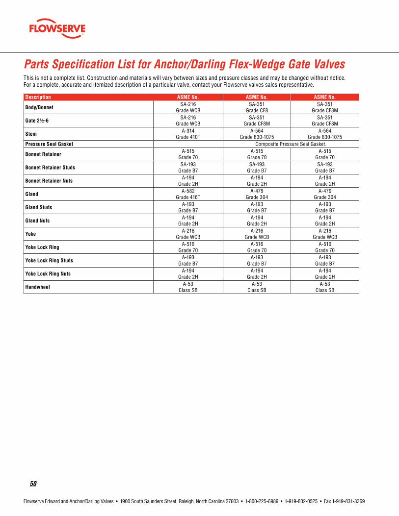
50
Flowserve Edward and Anchor/Darling Valves • 1900 South Saunders Street, Raleigh, North Carolina 27603 • 1-800-225-6989 • 1-919-832-0525 • Fax 1-919-831-3369
Description ASMENo. ASMENo. ASMENo.
Body/Bonnet SA-216 Grade WCB
SA-351 Grade CF8
SA-351 Grade CF8M
Gate21/2-6 SA-216 Grade WCB
SA-351 Grade CF8M
SA-351 Grade CF8M
Stem A-314 Grade 410T
A-564 Grade 630-1075
A-564 Grade 630-1075
PressureSealGasket Composite Pressure Seal Gasket.
BonnetRetainer A-515 Grade 70
A-515 Grade 70
A-515 Grade 70
BonnetRetainerStuds SA-193 Grade B7
SA-193 Grade B7
SA-193 Grade B7
BonnetRetainerNuts A-194 Grade 2H
A-194 Grade 2H
A-194 Grade 2H
Gland A-582 Grade 416T
A-479 Grade 304
A-479 Grade 304
GlandStuds A-193 Grade B7
A-193 Grade B7
A-193 Grade B7
GlandNuts A-194 Grade 2H
A-194 Grade 2H
A-194 Grade 2H
Yoke A-216 Grade WCB
A-216 Grade WCB
A-216 Grade WCB
YokeLockRing A-516 Grade 70
A-516 Grade 70
A-516 Grade 70
YokeLockRingStuds A-193 Grade B7
A-193 Grade B7
A-193 Grade B7
YokeLockRingNuts A-194 Grade 2H
A-194 Grade 2H
A-194 Grade 2H
Handwheel A-53 Class SB
A-53 Class SB
A-53 Class SB
This is not a complete list. Construction and materials will vary between sizes and pressure classes and may be changed without notice. For a complete, accurate and itemized description of a particular valve, contact your Flowserve valves sales representative.
Parts Specification List for Anchor/Darling Flex-Wedge Gate Valves

flowserve.com
51
Flowserve Edward and Anchor/Darling Valves • 1900 South Saunders Street, Raleigh, North Carolina 27603 • 1-800-225-6989 • 1-919-832-0525 • Fax 1-919-831-3369
Features• Carbon, stainless or special alloys
• Bolted bonnet
• Available Stellite seat, disc and backseat
• Seat-guided disc
• Various combinations of seat and stem material
• Uniform distribution of sealing pressure
Pressure Class 150 (PN 25)Fig. No. Type Ends NPS(DN)
BGT01U Gate Butt Weld 21/2 (65) thru 24 (600)
BGT01C Gate Flanged 21/2 (65) thru 24 (600)
Flex-Wedge Stop Valves, Class 150
Dimensions – Flex Wedge, Butt Weld end only. Flanged dimensions available on request.
Black numerals are in inches and poundsColored numerals are in millimeters and kilograms
Figure No. BGT01U/BGT01C
NPS 21/2 3 4 6 8 10 12 14 16 18 20 24DN 65 80 100 150 200 250 300 350 400 450 500 600
B9.5 11.1 12.0 15.9 16.5 18.0 19.8 22.5 24.0 26.0 28.0 32.0241 282 305 404 419 457 503 572 610 660 711 813
D23.0 25.0 29.0 35.0 46.0 50.0 61.0 64.0 70.0 78.0 87.0 98.0584 635 737 889 1,168 1,270 1,549 1,626 1,778 1,981 2,210 2,489
E12.0 12.0 12.0 12.0 12.0 12.0 18.0 12.0 12.0 12.0 12.0 18.0305 305 305 305 305 305 457 305 305 305 305 457
Weight Approx (lbs.)80 125 175 265 440 600 840 1100 1450 1835 2400 3150
36.2 56.7 79.4 120.2 199.6 272.1 381 499 657.7 832.3 1,088.6 1,428.8Cv 375 550 1025 2425 4500 7150 10,425 12,925 17,375 22,450 28,225 41,725
Refer to page 50 for materials of construction. Refer to pages 203 through 238 for the applicable pressure ratings.
B
D
E

52
Flowserve Edward and Anchor/Darling Valves • 1900 South Saunders Street, Raleigh, North Carolina 27603 • 1-800-225-6989 • 1-919-832-0525 • Fax 1-919-831-3369
Standard Features• Carbon, stainless or special alloys
• Bolted bonnet
• Available Stellite seat, disc and backseat
• Seat-guided disc
• Various combinations of seat and stem material
• Uniform distribution of sealing pressure
Flex-Wedge Stop Valves, Class 300
Pressure Class 300 (PN 50)Fig. No. Type Ends NPS(DN)
CGT01U Flex Wedge Gate Butt Weld 21/2 (65) thru 24 (600)
CGT01C Flex Wedge Gate Flanged 21/2 (65) thru 24 (600)
Dimensions – Flex WedgeBlack numerals are in inches and pounds
Colored numerals are in millimeters and kilograms
FigureNo.CGT01U/CGT01CNPS 2-1/2 3 4 6 8 10 12 14 16 18 20 24DN 65 80 100 150 200 250 300 350 400 450 500 600
B9.5 11.1 12 15.9 16.5 18 19.8 30 33 36 39 45241 282 305 404 419 437 503 762 838 914 991 1,143
D23 25 29 40 47 54 62 66 76 83 90 103
584 635 737 1,016 1,194 1,372 1,575 1,676 1,930 2,108 2,286 2,616
E12 12 12 12 18 12 18 18 18 24 18 18
305 305 305 305 457 305 457 457 457 610 457 457
Weight Approx (lbs.)60 125 175 375 560 850 1,245 1,400 1,850 2,385 2,950 5,500
27.2 56.7 79.4 170.1 254.0 385.6 564.7 635.0 839.2 1,081.8 1,338.1 2,494.8Cv 375 550 1,025 2,425 4,500 7,150 10,425 12,925 17,375 21,800 27,500 40,825
Refer to page 50 for materials of construction. Refer to pages 203 through 238 for the applicable pressure ratings.
B
D
E

flowserve.com
53
Flowserve Edward and Anchor/Darling Valves • 1900 South Saunders Street, Raleigh, North Carolina 27603 • 1-800-225-6989 • 1-919-832-0525 • Fax 1-919-831-3369
Flex-Wedge Stop Valves, Class 600
B
D
E
Dimensions – Flex WedgeBlack numerals are in inches and pounds
Colored numerals are in millimeters and kilograms
FigureNo.EGT01U/EGT01C, EGT05U/EGT05C
NPS 21/2 3 4 6 8 10 12 14 16 18 20 24DN 65 80 100 150 200 250 300 350 400 450 500 600
B8.5 10 12 18 23 28 32 35 39 43 47 55216 254 305 457 584 711 813 889 991 1,092 1,194 1,399
D21 29 31 42 47 57 65 69 77 83 98 110
533 737 787 1,067 1,194 1,448 1,651 1,753 1,955 2,108 2,489 2,794
E12 12 12 12 18 12 12 12 18 18 18 36
305 305 305 305 457 305 305 305 457 457 457 914
Weight Approx (lbs.)75 130 215 550 750 925 1,495 1,900 2,645 3,760 5,270 7,500
34.0 59.0 97.0 249.5 340.2 420.6 678.1 861.8 1,199.8 1,705.5 2,390.5 3,402Cv 375 550 1,025 2,375 4,225 6,625 9,850 12,025 15,900 20,100 24,900 36,525
Refer to page 50 for materials of construction. Refer to pages 203 through 238 for the applicable pressure ratings.
Standard Features• Carbon, stainless or special alloys
• Bolted bonnet or pressure seal
• Available Stellite seat, disc and backseat
• Seat-guided disc
• Various combinations of seat and stem material
• Uniform distribution of sealing pressure
Pressure Class 600 (PN 110)Fig. No. Type Ends NPS(DN)
EGT01U Bolted Bonnet Flex Wedge Gate Butt Weld 21/2 (65) thru 24 (600)
EGT01C Bolted Bonnet Flex Wedge Gate Flanged 21/2 (65) thru 24 (600)
EGT05U Pressure Seal Flex Wedge Gate Butt Weld 21/2 (65) thru 24 (600)
EGT05C Pressure Seal Flex Wedge Gate Flanged 21/2 (65) thru 24 (600)

54
Flowserve Edward and Anchor/Darling Valves • 1900 South Saunders Street, Raleigh, North Carolina 27603 • 1-800-225-6989 • 1-919-832-0525 • Fax 1-919-831-3369
Dimensions – Flex WedgeBlack numerals are in inches and pounds
Colored numerals are in millimeters and kilograms
FigureNo.FGT05U/FGT05CNPS 21/2 3 4 6 8 10 12 14 16 18 20 24DN 65 80 100 150 200 250 300 350 400 450 500 600
B10 12 14 20 26 31 36 39 43 48 50 59
254 305 356 508 660 787 914 991 1,092 1,219 1,270 1,499
D26 28 31 46 48 55 64 72 84 95 102 112
635 711 787 1,168 1,219 1,397 1,626 1,829 2,134 2,413 2,591 2,845
E12 12 18 12 18 18 18 12 18 12 18 12
305 305 457 305 457 457 457 305 457 305 457 305
G— — — 11 11 15 15 15 16 21 22 23— — — 279 279 381 381 381 406 533 559 584
Weight Approx (lbs.)160 160 225 660 910 1,500 2,030 2,600 3,500 5,620 7,920 11,50072.6 72.6 102 299.4 412.8 680.4 920.8 1,270 1,588 2,549 3,593 5,262
Cv 300 500 950 2,175 3,825 6,125 8,850 10,875 14,325 18,300 22,875 33,275
Refer to page 50 for materials of construction. Refer to pages 203 through 238 for the applicable pressure ratings.
Flex-Wedge Stop Valves, Class 900
Standard Features• Carbon, stainless or special alloys
• Pressure seal available
• Available Stellite seat, disc and backseat
• Seat-guided disc
• Various combinations of seat and stem material
• Uniform distribution of sealing pressure
Pressure Class 900 (PN 150)Fig. No. Type Ends NPS(DN)
FGT05U Flex Wedge Gate Butt Weld 21/2 (65) thru 24 (600)
FGT05C Flex Wedge Gate Flanged 21/2 (65) thru 24 (600)
D
G
E
B

flowserve.com
55
Flowserve Edward and Anchor/Darling Valves • 1900 South Saunders Street, Raleigh, North Carolina 27603 • 1-800-225-6989 • 1-919-832-0525 • Fax 1-919-831-3369
Dimensions – Flex WedgeBlack numerals are in inches and pounds
Colored numerals are in millimeters and kilograms
FigureNo.GGT05U/GGT05CNPS 21/2 3 4 6 8 10 12 14 16 18 20 24DN 65 80 100 150 200 250 300 350 400 450 500 600
B10 12 16 22 28 34 39 42 47 53 58 68
254 305 406 559 711 864 991 1,067 1,194 1,346 1,473 1,727
D28 30 34 46 53 60 68 78 89 101 114 128711 762 864 1,168 1,346 1,524 1,727 1,981 2,261 2,565 2,896 3,251
E12 12 12 18 18 12 18 12 12 12 18 18
305 305 305 457 457 305 457 305 305 305 457 457
Weight Approx (lbs.)250 290 410 760 1,420 1,920 3,350 4,200 5,860 7,850 9,200 15,250
113.4 131.5 186.0 340.2 644.1 870.9 1,520 1,905 2,658 3,561 4,173 6,917Cv 300 450 800 1,875 3,275 5,250 7,525 9,175 12,150 15,500 19,600 28,775
Refer to page 50 for materials of construction. Refer to pages 203 through 238 for the applicable pressure ratings.
Flex-Wedge Stop Valves, Class 1500
Standard Features• Carbon, stainless or special alloys
• Pressure seal
• Available Stellite seat, disc and backseat
• Seat-guided disc
• Various combinations of seat and stem material
• Uniform distribution of sealing pressure
Pressure Class 1500 (PN 260)Fig. No. Type Ends NPS(DN)
GGT05U Flex Wedge Gate Butt Weld 21/2 (65) thru 24 (600)
GGT05C Flex Wedge Gate Flanged 21/2 (65) thru 24 (600)
D
G
E
B

56
Flowserve Edward and Anchor/Darling Valves • 1900 South Saunders Street, Raleigh, North Carolina 27603 • 1-800-225-6989 • 1-919-832-0525 • Fax 1-919-831-3369
Pageintentionallyleftblank

flowserve.com
57
Flowserve Edward and Anchor/Darling Valves • 1900 South Saunders Street, Raleigh, North Carolina 27603 • 1-800-225-6989 • 1-919-832-0525 • Fax 1-919-831-3369
EdwardGlobeandStop-CheckValves

58
Flowserve Edward and Anchor/Darling Valves • 1900 South Saunders Street, Raleigh, North Carolina 27603 • 1-800-225-6989 • 1-919-832-0525 • Fax 1-919-831-3369
Features and Description of Edward Bolted Bonnet Globe Valves
1.
2.
3.
4. 6.
7.
8.9.
5.
1.Handwheel is rugged and knobbed to provide sure grip even when wearing gloves.
2.Stem has ACME threads, is grounded to a fine finish and is hardened to resist wear.
3.Yokebushing material has low coefficient of friction, which substantially reduces torque and stem wear and eliminates galling. Mechanical upset locks yoke bushing to yoke.
4. Bolted bonnet joint utilizes a spiral-wound gasket for positive sealing and four-bolt design for ease of assembly. Bonnet has pilot extension to ensure proper alignment and positive metal-to-metal stop to prevent over-compression of gasket.
5. Integral hardsurfaced seat provides positive shutoff and long seat life.
6.Stempackingsystem utilizes flexible graphite packing material with anti-extrusion rings for optimum sealability and life.
7.Integralbackseat provides a secondary stem seal backup for positive shutoff and leak protection.
8.Body utilizes optimized flow passages to minimize flow direction changes and reduce pressure drop.
9.Body-guideddisc utilizes anti-thrust rings to eliminate misalignment, galling and stem bending.

flowserve.com
59
Flowserve Edward and Anchor/Darling Valves • 1900 South Saunders Street, Raleigh, North Carolina 27603 • 1-800-225-6989 • 1-919-832-0525 • Fax 1-919-831-3369
EdwardboltedbonnetvalvesfornuclearserviceareavailableinClass600only.RefertoForgedSteelCatalog,EVENCT0001forstop,stop-checkandpistoncheckvalvedimensions(Class800dimensionsapplytoNuclearClass600Valves).
Parts Specification List for Edward Bolted Bonnet Globe Valves
This is not a complete list. Construction and materials will vary between sizes and pressure classes and may be changed without notice. For a complete, accurate and itemized description of a particular valve, contact your Flowserve Edward and Anchor/Darling valves sales representative.
DescriptionBolted Bonnet
ASME/ASTMNo.
Body/Bonnet SA-105-
Disc* AISI 615BodySeat Stellite 21
Stem A-582T-416
Capscrews SA-193Grade B-7
Gasket Spiral WoundNon Asbestos
Packing Flexible Graphite System
Gland A-582Grade 80 - 55 - 06
YokeBushing B-150 C61900 or C6230100Handwheel/Handle Malleable or Ductile IronStemNut Mild Steel Plated
EyeBolt A-582T-416
EyeBoltNut A-194Grade 8
EyeBoltPin AISIGrade 4140
Spring** A-313T-302
* Check and stop-check valve discs are A565T-616** Check valves and stop-check valves
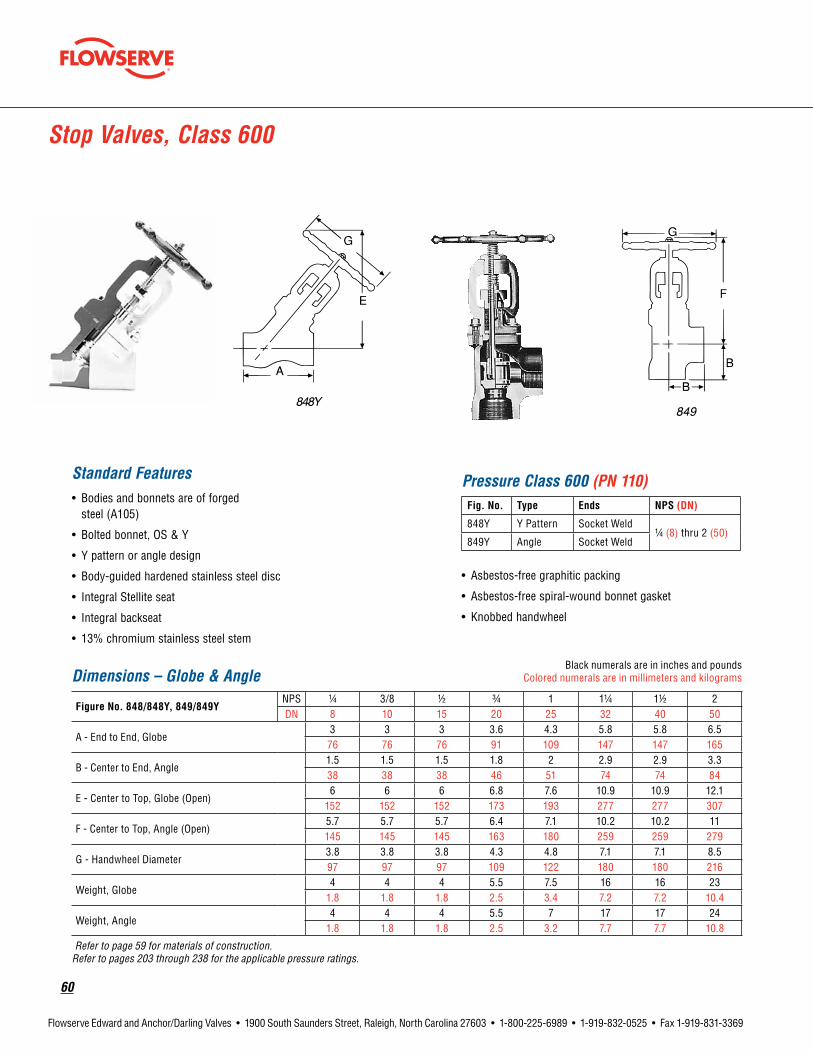
60
Flowserve Edward and Anchor/Darling Valves • 1900 South Saunders Street, Raleigh, North Carolina 27603 • 1-800-225-6989 • 1-919-832-0525 • Fax 1-919-831-3369
Stop Valves, Class 600
Standard Features• Bodies and bonnets are of forged
steel (A105)
• Bolted bonnet, OS & Y
• Y pattern or angle design
• Body-guided hardened stainless steel disc
• Integral Stellite seat
• Integral backseat
• 13% chromium stainless steel stem
• Asbestos-free graphitic packing
• Asbestos-free spiral-wound bonnet gasket
• Knobbed handwheel
Pressure Class 600 (PN 110)Fig. No. Type Ends NPS(DN)
848Y Y Pattern Socket Weld1/4 (8) thru 2 (50)
849Y Angle Socket Weld
Dimensions – Globe & AngleBlack numerals are in inches and pounds
Colored numerals are in millimeters and kilograms
FigureNo.848/848Y,849/849YNPS 1/4 3/8 1/2 3/4 1 11/4 11/2 2DN 8 10 15 20 25 32 40 50
A - End to End, Globe3 3 3 3.6 4.3 5.8 5.8 6.5
76 76 76 91 109 147 147 165
B - Center to End, Angle1.5 1.5 1.5 1.8 2 2.9 2.9 3.338 38 38 46 51 74 74 84
E - Center to Top, Globe (Open)6 6 6 6.8 7.6 10.9 10.9 12.1
152 152 152 173 193 277 277 307
F - Center to Top, Angle (Open)5.7 5.7 5.7 6.4 7.1 10.2 10.2 11145 145 145 163 180 259 259 279
G - Handwheel Diameter3.8 3.8 3.8 4.3 4.8 7.1 7.1 8.597 97 97 109 122 180 180 216
Weight, Globe4 4 4 5.5 7.5 16 16 23
1.8 1.8 1.8 2.5 3.4 7.2 7.2 10.4
Weight, Angle4 4 4 5.5 7 17 17 24
1.8 1.8 1.8 2.5 3.2 7.7 7.7 10.8
Refer to page 59 for materials of construction. Refer to pages 203 through 238 for the applicable pressure ratings.

flowserve.com
61
Flowserve Edward and Anchor/Darling Valves • 1900 South Saunders Street, Raleigh, North Carolina 27603 • 1-800-225-6989 • 1-919-832-0525 • Fax 1-919-831-3369
• Asbestos-free graphitic packing
• Asbestos-free spiral-wound bonnet gasket
• Knobbed handwheel
Stop-Check Valves, Class 600
Standard Features• Bodies and bonnets are of forged
steel (A105)
• Bolted bonnet, OS & Y
• Y pattern or angle design
• Body-guided hardened stainless steel disc
• Integral Stellite seat
• Integral backseat
• 13% chromium stainless steel stem
• Asbestos-free graphitic packing
• Asbestos-free spiral wound bonnet gasket
• Knobbed handwheel
• Stainless steel spring
Pressure Class 600 (PN 110)Fig. No. Type Ends NPS(DN)
868Y Y Pattern Socket Weld1/4 (8) thru 2 (50)
869Y Angle Socket Weld
Dimensions – Globe & AngleBlack numerals are in inches and pounds
Colored numerals are in millimeters and kilograms
FigureNo.868/868Y,869/869YNPS 1/4 3/8 1/2 3/4 1 11/4 11/2 2DN 8 10 15 20 25 32 40 50
A - End to End, Globe3 3 3 3.6 4.3 5.8 5.8 6.5
76 76 76 91 109 147 147 165
B - Center to End, Angle1.5 1.5 1.5 1.8 2 2.9 2.9 3.338 38 38 46 51 74 74 84
E - Center to Top, Globe (Open)6 6 6 6.8 7.6 10.9 10.9 12.1
152 152 152 173 193 277 277 307
F - Center to Top, Angle (Open)5.7 5.7 5.7 6.4 7.1 10.2 10.2 11145 145 145 163 180 259 259 279
G - Handwheel Diameter3.8 3.8 3.8 4.3 4.8 7.1 7.1 8.597 97 97 109 122 180 180 216
Weight, Globe4 4 4 5.5 7.5 16 16 23
1.8 1.8 1.8 2.5 3.4 7.2 7.2 10.4
Weight, Angle4 4 4 5.5 7 17 17 24
1.8 1.8 1.8 2.5 3.2 7.7 7.7 10.8Refer to page 59 for materials of construction. Refer to pages 203 through 238 for the applicable pressure ratings.

62
Flowserve Edward and Anchor/Darling Valves • 1900 South Saunders Street, Raleigh, North Carolina 27603 • 1-800-225-6989 • 1-919-832-0525 • Fax 1-919-831-3369
1.Stem has ACME threads, is ground to a fine finish and is hardened to resist wear.
2.Yokebushing material has low coefficient of friction, which substantially reduces torque and stem wear and eliminates galling. Mechanical upset locks yoke bushing to yoke.
3.Yoke-bonnetassembly is two piece to facilitate disassem-bly for faster in-line internal repairs.
4. Inclined stem construction and optimum flow shape mini-mize flow direction changes and reduce pressure drop.
5.Body-guideddisc utilizes anti-thrust rings to eliminate misalignment, galling and stem bending.
6. Integral hardsurfaced seat provides positive shutoff and long seat life.
7.Handwheel on smaller size valves is rugged and knobbed to provide sure grip even when wearing gloves. Impactor
handle or handwheel on larger, higher pressure valves provides many times the closing force of an ordinary handwheel for positive seating.
8.Threadedbonnet has ACME threads for resistance to galling and ease of disassembly. Unwelded models utilize a graphitic gasket for dependable sealing. Welded models employ a fillet weld (canopy weld on stainless steel valves) for absolute protection from body-bonnet leakage.
9.Stempackingsystem utilizes flexible graphite packing material with carbon fiber anti-extrusion rings for optimum sealability and life.
10.Bonnetlockingcollar (unwelded valves only).
11. Bonnet seal ring is die-formed flexible graphite gasket seated to a prescribed bonnet torque to provide reliable bonnet seal.
12.Integralbackseatprovides a secondary stem seal backup for positive shutoff and leak protection.
Features and Description of Edward Univalve® Globe Valves7.
8.
9.
10.
11.
12.
1.
2.
3.
4.
5.6.
Welded
Unwelded
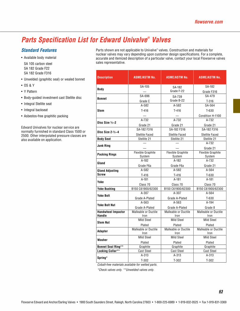
flowserve.com
63
Flowserve Edward and Anchor/Darling Valves • 1900 South Saunders Street, Raleigh, North Carolina 27603 • 1-800-225-6989 • 1-919-832-0525 • Fax 1-919-831-3369
Parts Specification List for Edward Univalve® ValvesStandard Features• Available body material
SA 105 carbon steel SA 182 Grade F22 SA 182 Grade F316
• Unwelded (graphitic seal) or wealed bonnet
• OS & Y
• Y Pattern
• Body-guided investment cast Stellite disc
• Integral Stellite seat
• Integral backseat
• Asbestos-free graphitic packing
Edward Univalves for nuclear service are normally furnished in standard Class 1500 or 2500. Other interpolated pressure classes are also available on application.
Parts shown are not applicable to Univalve® valves. Construction and materials for nuclear valves may vary depending upon customer design specifications. For a complete, accurate and itemized description of a particular valve, contact your local Flowserve valves sales representative.
Description ASME/ASTMNo. ASME/ASTMNo. ASME/ASTMNo.
BodySA-105
—SA-182
Grade F-22SA-182
Grade F316
BonnetSA-696
Grade CSA-739
Grade B-22SA-479
T-316
Stem
A-582
T-416
—
A-582
T-416
—
SA-564
T-630
Condition H-1100
DiscSize1/2−2A-732
Grade 21
A-732
Grade 21
A-732
Grade 21
DiscSize2-1/2−4SA-182 F316
Stellite Faced
SA-182 F316
Stellite Faced
SA-182 F316
Stellite FacedBodySeat Stellite 21 Stellite 21 Stellite 21
JunkRing—
—
—
—
A-732
Grade 21
PackingRings Flexible Graphite System
Flexible Graphite System
Flexible Graphite System
GlandA-182
Grade F6a
A-182
Grade F6a
A-732
Grade 21
GlandAdjustingScrew
A-582
T-416
A-582
T-416
A-564
T-630
YokeA-181
Class 70
A-181
Class 70
A-181
Class 70YokeBushing B150 C61900/62300 B150 C61900/62300 B150 C61900/62300
YokeBoltA-307
Grade A-Plated
A-307
Grade A-Plated
A-564
T-630
YokeBoltNutA-563
Grade A-Plated
A-563
Grade A-Plated
A-194
Grade 8HandwheelImpactorHandle
Malleable or Ductile Iron
Malleable or Ductile Iron
Malleable or Ductile Iron
StemNutMild Steel
Plated
Mild Steel
Plated
Mild Steel
Plated
Adapter Malleable or Ductile Iron
Malleable or Ductile Iron
Malleable or Ductile Iron
WasherMild Steel
Plated
Mild Steel
Plated
Mild Steel
PlatedBonnetSealRing** Graphite Graphite GraphiteLockingCollar** Cast Steel Cast Steel Cast Steel
Spring*A-313
T-302
A-313
T-302
A-313
T-302Cobalt-free materials available for wetted parts.
*Check valves only. **Unwelded valves only.
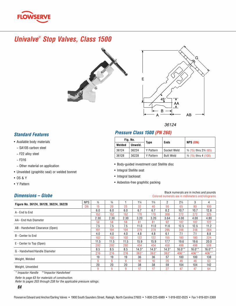
64
Flowserve Edward and Anchor/Darling Valves • 1900 South Saunders Street, Raleigh, North Carolina 27603 • 1-800-225-6989 • 1-919-832-0525 • Fax 1-919-831-3369
Univalve® Stop Valves, Class 1500
Standard Features• Available body materials
− SA105 carbon steel
− F22 alloy steel
− F316
− Other material on application
• Unwelded (graphitic seal) or welded bonnet
• OS & Y
• Y Pattern
• Body-guided investment cast Stellite disc
• Integral Stellite seat
• Integral backseat
• Asbestos-free graphitic packing
Pressure Class 1500 (PN 260)Fig. No.
Type Ends NPS(DN)Welded Unweld.
36124 36224 Y Pattern Socket Weld 1/2 (15) thru 21/2 (65)
36128 36228 Y Pattern Butt Weld 1/2 (15) thru 4 (100)
Dimensions – GlobeBlack numerals are in inches and pounds
Colored numerals are in millimeters and kilograms
Figure No. 36124, 36128, 36224, 36228NPS 1/2 3/4 1 11/4 11/2 2 21/2 3 4DN 15 20 25 32 40 50 65 80 100
A - End to End6.0 6.0 6.0 6.7 6.7 8.2 10.7 10.7 12.8152 152 152 170 170 208 272 272 325
AA - End Hub Diameter2.30 2.30 2.30 3.20 3.20 3.64 4.00 4.00 4.8058 58 58 81 81 92 102 102 122
AB - Handwheel Clearance (Open)7.5 7.5 7.5 11.0 11.0 11.6 12.5 12.5 11.2191 191 191 279 279 295 318 318 284
B - Center to End4.0 4.0 4.0 4.8 4.8 6.1 7.1 7.1 8.8102 102 102 122 122 155 180 180 224
E - Center to Top (Open)11.5 11.5 11.5 15.9 15.9 17.7 19.6 19.6 20.0292 292 292 404 404 450 498 498 508
G - Handwheel/Handle Diameter8.5 8.5 8.5 14.3* 14.3* 14.3* 16.0** 16.0** 16.0**216 216 216 363* 363* 363* 406** 406** 406**
Weight, Welded19 19 19 36 36 57 100 100 1389 9 9 16 16 26 46 46 63
Weight, Unwelded20 20 20 38 38 59 104 104 1429 9 9 17 17 27 47 47 64
* Impactor Handle **Impactor Handwheel
Refer to page 63 for materials of construction. Refer to pages 203 through 238 for the applicable pressure ratings.

flowserve.com
65
Flowserve Edward and Anchor/Darling Valves • 1900 South Saunders Street, Raleigh, North Carolina 27603 • 1-800-225-6989 • 1-919-832-0525 • Fax 1-919-831-3369
Univalve® Stop-Check Valves, Class 1500
Standard Features• Available body materials
− SA105 carbon steel
− F22 alloy steel
− F316 stainless steel
• Unwelded (graphitic seal) or welded bonnet
• OS & Y
• Y Pattern
• Body-guided investment cast Stellite disc
• Integral Stellite seat
• Integral backseat
• Asbestos-free graphitic packing
Pressure Class 1500 (PN 260)Fig. No.
Type Ends NPS(DN)Welded Unweld.
36164 36264 Y Pattern Socket Weld 1/2 (15) thru 21/2 (65)
36168 36268 Y Pattern Butt Weld 1/2 (15) thru 4 (100)
Dimensions – GlobeBlack numerals are in inches and pounds
Colored numerals are in millimeters and kilograms
Figure No. 36164, 36168, 36264, 36268NPS 1/2 3/4 1 11/4 11/2 2 21/2 3 4DN 15 20 25 32 40 50 65 80 100
A - End to End6.0 6.0 6.0 6.7 6.7 8.2 10.7 10.7 12.8152 152 152 170 170 208 272 272 325
AA - End Hub Diameter2.30 2.30 2.30 3.20 3.20 3.64 4.00 4.00 4.8058 58 58 81 81 92 102 102 122
AB - Handwheel Clearance (Open)7.5 7.5 7.5 11.0 11.0 11.6 12.5 12.5 11.2191 191 191 279 279 295 318 318 284
B - Center to End4.0 4.0 4.0 4.8 4.8 6.1 7.1 7.1 8.8102 102 102 122 122 155 180 180 224
E - Center to Top (Open)11.5 11.5 11.5 15.9 15.9 17.7 19.6 19.6 20.0292 292 292 404 404 450 498 498 508
G - Handwheel/Handle Diameter8.5 8.5 8.5 14.3* 14.3* 14.3* 16.0** 16.0** 16.0**216 216 216 363* 363* 363* 406** 406** 406**
Weight, Welded19 19 19 36 36 57 100 100 1389 9 9 16 16 26 46 46 63
Weight, Unwelded20 20 20 38 38 59 104 104 1429 9 9 17 17 27 47 47 64
* Impactor Handle ** Impactor Handwheel
Refer to page 63 for materials of construction. Refer to pages 203 through 238 for the applicable pressure ratings.
36164

66
Flowserve Edward and Anchor/Darling Valves • 1900 South Saunders Street, Raleigh, North Carolina 27603 • 1-800-225-6989 • 1-919-832-0525 • Fax 1-919-831-3369
Univalve® Stop Valves, Class 2500
Standard Features• Available body material
− SA105 carbon steel
− F22 alloy steel
− F316 stainless steel
− Other material on application
• Unwelded (graphitic seal) or welded bonnet
• OS & Y
• Y Pattern
• Body-guided investment cast Stellite disc
• Integral Stellite seat
• Integral backseat
• Asbestos-free graphitic packing
Dimensions – GlobeBlack numerals are in inches and pounds
Colored numerals are in millimeters and kilograms
Figure No. 66124, 66128, 66224, 66228NPS 1/2 3/4 1 1-1/4 1-1/2 2 2-1/2 3 4DN 15 20 25 32 40 50 65 80 100
A - End to End6.0 6.0 6.0 6.7 6.7 10.7 12.8 12.8 12.8152 152 152 170 170 272 325 325 325
AA - End Hub Diameter2.30 2.30 2.30 3.20 3.20 4.00 4.80 4.80 4.8058 58 58 81 81 102 122 122 122
AB - Handwheel Clearance, (Open)7.5 7.5 7.5 9.8 9.8 11.6 11.2 11.2 11.2191 191 191 249 249 296 284 284 284
B - Center to End4.0 4.0 4.0 4.8 4.8 7.1 8.8 8.8 8.8102 102 102 122 122 180 224 224 224
E - Center to Top, (Open)11.5 11.5 11.5 14.6 14.6 18.6 20.0 20.0 20.0292 292 292 371 371 472 508 508 508
G - Handwheel/Handle Diameter8.5 8.5 8.5 11.0* 11.0* 14.3* 16.0** 16.0** 16.0**216 216 216 279* 279* 363* 406** 406** 406**
Weight, Welded19 19 19 34 34 79 142 142 1429 9 9 16 16 36 65 65 65
Weight, Unwelded20 20 20 36 36 83 146 146 1469 9 9 17 17 38 66 66 66
* Impactor Handle ** Impactor Handwheel
Refer to page 63 for materials of construction. Refer to pages 203 through 238 for the applicable pressure ratings.
Pressure Class 2500 (PN 420)Fig. No.
Type Ends NPS(DN)Welded Unweld.
66124 66224 Y Pattern Socket Weld 1/2 (15) thru 21/2 (65)
66128 66228 Y Pattern Butt Weld 1/2 (15) thru 4 (100)
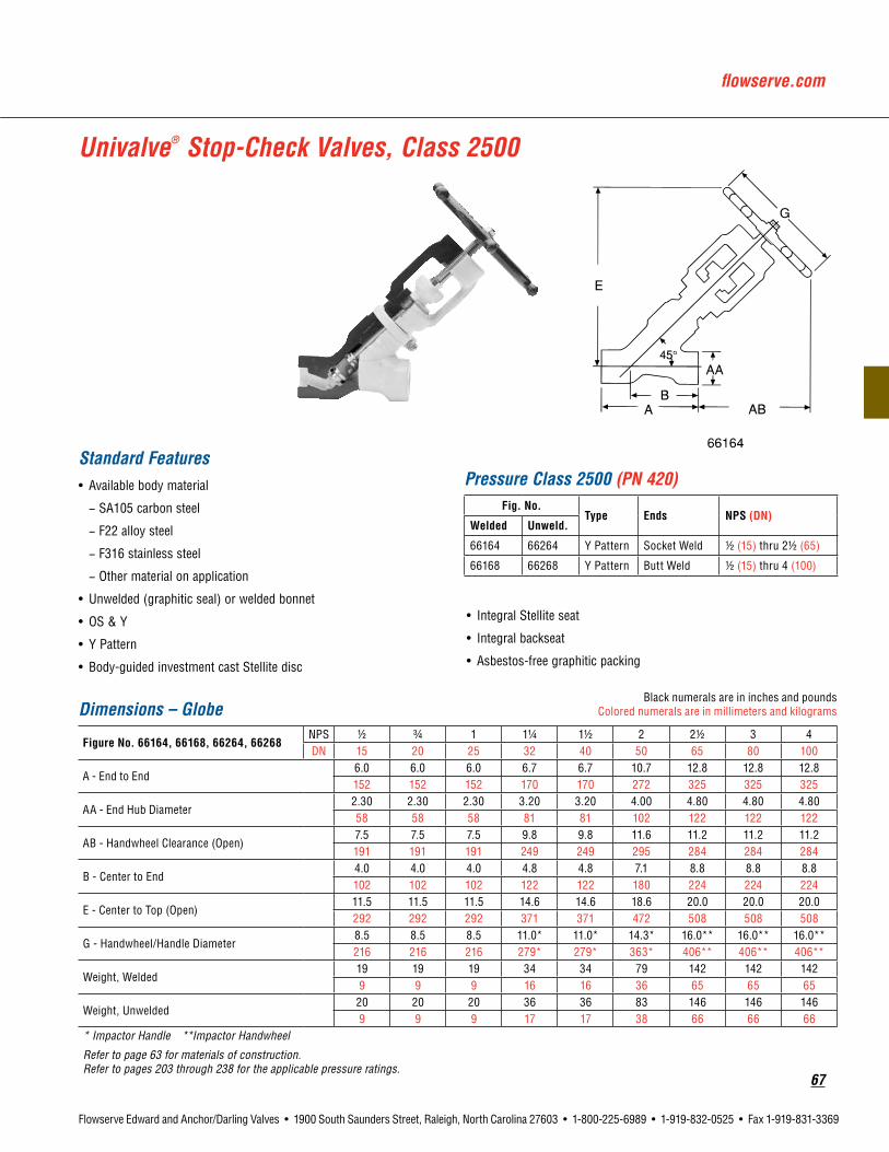
flowserve.com
67
Flowserve Edward and Anchor/Darling Valves • 1900 South Saunders Street, Raleigh, North Carolina 27603 • 1-800-225-6989 • 1-919-832-0525 • Fax 1-919-831-3369
Univalve® Stop-Check Valves, Class 2500
Standard Features• Available body material
− SA105 carbon steel
− F22 alloy steel
− F316 stainless steel
− Other material on application
• Unwelded (graphitic seal) or welded bonnet
• OS & Y
• Y Pattern
• Body-guided investment cast Stellite disc
• Integral Stellite seat
• Integral backseat
• Asbestos-free graphitic packing
Pressure Class 2500 (PN 420)Fig. No.
Type Ends NPS(DN)Welded Unweld.
66164 66264 Y Pattern Socket Weld 1/2 (15) thru 21/2 (65)
66168 66268 Y Pattern Butt Weld 1/2 (15) thru 4 (100)
Dimensions – GlobeBlack numerals are in inches and pounds
Colored numerals are in millimeters and kilograms
Figure No. 66164, 66168, 66264, 66268NPS 1/2 3/4 1 11/4 11/2 2 21/2 3 4DN 15 20 25 32 40 50 65 80 100
A - End to End6.0 6.0 6.0 6.7 6.7 10.7 12.8 12.8 12.8152 152 152 170 170 272 325 325 325
AA - End Hub Diameter2.30 2.30 2.30 3.20 3.20 4.00 4.80 4.80 4.8058 58 58 81 81 102 122 122 122
AB - Handwheel Clearance (Open)7.5 7.5 7.5 9.8 9.8 11.6 11.2 11.2 11.2191 191 191 249 249 295 284 284 284
B - Center to End4.0 4.0 4.0 4.8 4.8 7.1 8.8 8.8 8.8102 102 102 122 122 180 224 224 224
E - Center to Top (Open)11.5 11.5 11.5 14.6 14.6 18.6 20.0 20.0 20.0292 292 292 371 371 472 508 508 508
G - Handwheel/Handle Diameter8.5 8.5 8.5 11.0* 11.0* 14.3* 16.0** 16.0** 16.0**216 216 216 279* 279* 363* 406** 406** 406**
Weight, Welded19 19 19 34 34 79 142 142 1429 9 9 16 16 36 65 65 65
Weight, Unwelded20 20 20 36 36 83 146 146 1469 9 9 17 17 38 66 66 66
* Impactor Handle **Impactor Handwheel
Refer to page 63 for materials of construction. Refer to pages 203 through 238 for the applicable pressure ratings.
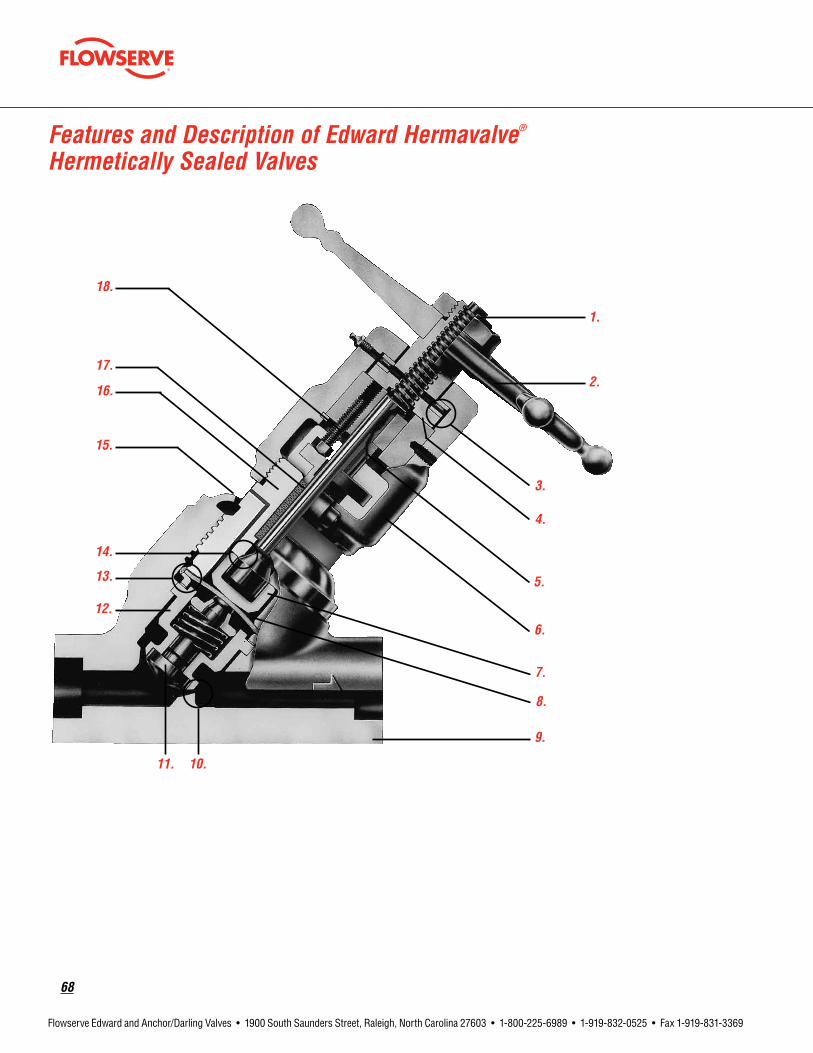
68
Flowserve Edward and Anchor/Darling Valves • 1900 South Saunders Street, Raleigh, North Carolina 27603 • 1-800-225-6989 • 1-919-832-0525 • Fax 1-919-831-3369
9.
8.
1.
2.
3.
4.
5.
6.
7.
10.11.
12.
13.
14.
15.
16.
17.
18.
Features and Description of Edward Hermavalve® Hermetically Sealed Valves

flowserve.com
69
Flowserve Edward and Anchor/Darling Valves • 1900 South Saunders Street, Raleigh, North Carolina 27603 • 1-800-225-6989 • 1-919-832-0525 • Fax 1-919-831-3369
Features and Description of Edward Hermavalve® Hermetically Sealed Valves1.Positionindicator shows whether the
valve is open or closed.
2.Handwheel is rugged and knobbed to permit sure grip even when wearing gloves.
3. Needle thrust bearings minimize torque. Their upper yoke location protects from heat and allows lubrication.
4.Yokebushing. Revolving bushing of aluminum bronze material has low coefficient of friction, substantially reduces torque, stem wear and eliminates galling.
5.Non-revolvingstem is stainless steel. It is ground to a fine finish and keyed to the yoke to prevent rotation and torsional stress on the diaphragm.
6.Yoke of carbon steel is electroless nickel plated for corrosion resistance.
7. Diaphragm disc is a unique shape that maximizes diaphragm life.
8. Diaphragm of multi-ply flexible metal provides a reliable primary stem seal.
9.Body with inclined stem construction and unique flow shape minimizes flow directional changes and cuts pressure drop.
10.Integralhardfacedseat of hard, heat-resistant hardfacing material is integrally welded to the body.
11.SolidStellitedisc ensures maximum seating life.
12.Discguideassembly ensures disc/seat alignment. Its completely encapsulated spring ensures full disc lift.
13. Diaphragm seal weld is a unique seal weld, which makes the diaphragm an integral part of the bonnet and eliminates a potential leak path past the stem.
14.Backseat provides a secondary stem seal backup.
15.Body-bonnetseal features leak-proof seal-welded construction. The weld is for seal only; the threaded section carries the pressure load. Canopy weld in stainless steel; fillet weld in carbon steel.
16. Bonnet is barstock steel with gall-resistant ACME threads to ensure easy disassembly from body.
17.Backuppacking with OS & Y design allows for inspection or addition of packing without disassembling valve.
18.Adjustableglandscrews with OS & Y design allow for easy access to packing adjustment, if necessary.
What is a Hermavalve? A Hermavalve is a hermetically sealed valve that cannot leak to the environment. The Edward Hermavalve cannot leak because it is double-seal welded:
1. The multi-ply flexible metal diaphragm is seal welded to the bonnet.
2. The body-to-bonnet joint is also seal welded.
This unique construction eliminates any potential leakage through a mechanical joint. It is more than just packless. It is hermetically sealed.
Zero leakage to environment—Welded, hermetic design and dependable metal diaphragm help to ensure zero leakage for the life of the valve. In approved services, the valve is warranted against leakage to the environment.
High-efficiency flow-shape—Unique flow shape ensures high CV comparable to or greater that conventionally packed valves—proven by extensive flow testing.
Non-revolving stem design—Ensures lowest possible operating torque and is the only absolute method of avoiding diaphragm damage caused by rotational forces from a revolving stem.
Two backup stem seals—1) Packing and 2) backseat provide backup seals.
Nuclear quality—Available to ASME Section III—Class 1, 2, 3.

70
Flowserve Edward and Anchor/Darling Valves • 1900 South Saunders Street, Raleigh, North Carolina 27603 • 1-800-225-6989 • 1-919-832-0525 • Fax 1-919-831-3369
Parts Specification List for Edward Hermavalve®
Construction and materials for nuclear valves may vary depending upon customer design specifications. For a complete, accurate and itemized description of a particular valve, contact your Flowserve Edward valves sales representative.
Description ASME/ASTMNo. ASME/ASTMNo.Body SA-105 SA-182 Grade F316Disc A-732 Grade 21 A-732 Grade 21BodySeat Stellite 21 Stellite 21Stem A-582 T-416 SA-564 T-630 Cond. H-1100JunkRing A-582 T-416 A-582 T-416Bonnet SA-696 Grade C SA-479 T316YokeBolt A-193 Grade B6 A-564 T-630Packing Flexible Graphite System Flexible Graphite SystemGland A-582 T-416 A-564 T-630RetainingRing Nickel-Plated Steel Nickel Plated SteelGlandAdjustingScrew A-193 Grade B6 A-564 T630StemGuideBushing A-696 Grade C Nickel Plated A-696 Grade C Nickel PlatedYokeBoltNut A-194 Grade 6F A-194 Grade 8Yoke A-216 Grade WCB Nickel Plated A-216 Grade WCB Nickel PlatedYokeBushing B-150 Alloy C61900 - C62300 B-150 Alloy C61900 - C62300DrivePin A-564 T630 A-564 T630Key A-331 Grade 4140 A-331 Grade 4140SpringHousing A-582 T-416 A-564 T-630DiaphragmRing SA-696 Grade C SA-479 T-316DiaphragmAssembly B-670 Alloy 718 (Inconel) B-670 Alloy 718 (Inconel)Diaphragm Disc A-732 Grade 21 A-732 Grade 21Shims A-167 T-316 A-167 T-316Disc Collar A-565 Grade 616 A-565 Grade 616Spring Inconel X-750 Inconel X-750Handwheel Malleable or Ductile Iron Malleable or Ductile IronHandwheelNut Nickel-Plated Steel Nickel-Plated Steel Indicator A-479 T-316 A-479 T-316ThrustBearing Steel SteelLube Fitting Nickel-Plated Steel Nickel-Plated SteelNote: Cobalt-free materials available for wetted parts.

flowserve.com
71
Flowserve Edward and Anchor/Darling Valves • 1900 South Saunders Street, Raleigh, North Carolina 27603 • 1-800-225-6989 • 1-919-832-0525 • Fax 1-919-831-3369
Hermavalve® Hermetically Sealed Valves ASME SECTION III – Code Class 1, 2, or 3Nuclear Service GuaranteeZeroleakagetoenvironmentfor40yearsor4000cycles,orwereplacethevalveat NOCOST.Fordetailedwarrantystatement,consultyourFlowserveEdwardvalves representative.
Standard Features• SA105 or SA182 Grade F316
body and bonnet
• Seal-welded diaphragm and seal-welded body/bonnet joint
• OS & Y
• Y Pattern
• Non-revolving stem with position indicator
• Back-up asbestos-free graphitic packing and secondary stem backseat
• Integral hardfaced seat
• Knobbed handwheel
Pressure Class 1690 (PN 290)Fig. No. Material Ends Port NPS(DN)
15004 Carbon Steel Socket Weld Regular1/2 (15) thru 2 (50)
15008 Carbon Steel Butt Weld Regular
15014 Carbon Steel Socket Weld Reduced1 (25) thru 2-1/2 (40)
15018 Carbon Steel Butt Weld Reduced
15104 Stainless Steel Socket Weld Regular1/2 (15) thru 2 (50)
15108 Stainless Steel Butt Weld Regular
15114 Stainless Steel Socket Weld Reduced1 (25) thru 2-1/2 (40)
15118 Stainless Steel Butt Weld Reduced
DimensionsBlack numerals are in inches and pounds
Colored numerals are in millimeters and kilograms
FigureNo.15004,15008,15014,15018,15104,15108,15114,15118
RegularPort ReducedPortNPS 1/2 3/4 1 1-1/2 2 1 1-1/2* 2 2-1/2DN 15 20 25 40 50 25 40 50 65
A - End to End5.5 5.5 6.62 8.7 10 5.5 6.62 8.7 10140 140 168 220 254 140 168 220 254
AA - End Hub Diameter2.06 2.06 2.12 3.4 3.4 2.06 2.12 3.4 3.452 52 54 86 86 52 54 86 86
AB - Handwheel Clearance (Open)4.62 4.62 5.69 9.06 10.88 4.62 5.69 9.06 10.88117 117 145 230 276 117 145 230 276
E - Center to Top9.12 9.12 11.19 16 18.5 9.12 11.19 16 18.5232 232 284 406 470 232 284 406 470
B - Center to End3.8 3.8 4.62 6 6.86 3.8 4.62 6 6.8697 97 117 152 174 97 117 152 174
G - Handwheel Diameter7.12 7.12 8.5 11.5 15 7.12 8.5 11.5 15181 181 216 292 381 181 216 292 381
Weight18 18 30 73 106 18 30 73 1068 8 14 33 48 8 14 33 48
*Available in buttweld only.
Refer to page 70 for materials of construction. Refer to pages 203 through 238 for the applicable pressure ratings.

72
Flowserve Edward and Anchor/Darling Valves • 1900 South Saunders Street, Raleigh, North Carolina 27603 • 1-800-225-6989 • 1-919-832-0525 • Fax 1-919-831-3369
Features and Description of Flowserve Edward Stop-Check (Non-Return) ValvesFlowserve Edward stop-check (non-return) valves offer the same tight-sealing performance as Edward stop valves, and at the same time, give check valve protection in the event of fluid back flow. Edward stop-check valves are commonly used to prevent back flow from a header fed from two or more sources when there is a loss of pressure in one of the sources—for example, the boiler outlet to a common header or at the feedwater heater outlets.
EqualizerFlowserve Edward cast steel stop-check valves are equipped with an Equalizer pipe. Acting as an external pressure balancing pipeline, the Equalizer connects the zone above the disc with the lower pressure area in the valve outlet (see drawing above). This reduces pressure above the disc, and as a result, causes the higher pressure below the disc to raise the disc to full lift. The Equalizer helps reduce pressure drop and disc-piston movement and wear.
Otherfeaturesarethesameasthosedefinedonpage74forstopvalves.
Angle
Globe
Flite-Flow®
Equalizerpipefor full disc lift
NOTE 1: Guide ribs are hardfaced on Flite-Flow and some angle pattern valves.
NOTE 1

flowserve.com
73
Flowserve Edward and Anchor/Darling Valves • 1900 South Saunders Street, Raleigh, North Carolina 27603 • 1-800-225-6989 • 1-919-832-0525 • Fax 1-919-831-3369
Parts Specification List for Edward Globe Valves, Stop-Check and Piston Lift Check
Description(1) ASME/ASTMNo. ASME/ASTMNo. ASME/ASTMNo. ASME/ASTMNo.
Body/Bonnet* SA-216 Grade WCB
SA-216 Grade WCC
SA-217 Grade WC9
SA-351 Grade CF8M
Disc SA-105 —
SA-105 —
A-182 Grade F22
A-182 Grade F316
Body-GuidedDiscNut A-216 Grade WCB
A-216 Grade WCB
A-217 Grade WC9
A-182 Grade F316
Stem A-182 Grade F6a
A-182 Grade F6a
A-565 Grade 616 HT
A-638 Grade 660 T2
YokeBushing B-148 Alloy 95400
B-148 Alloy 95400
B-148 Alloy 95400
B-148 Alloy 95400
PackingRings Flexible Graphite inner rings and suitable anti-extrusion rings.
JunkRings A-108 Grade 1018-20 MnPO4 Plated
A-108 Grade 1018-20 MnPO4 Plated
A-108 Grade 1018-20 MnPO4 Plated
A-182 Grade F316/Stellite I.D.
PressureSealGasket Composite Pressure Seal Gasket.
SpacerRing A-668 Grade 4140 MnPO4 Plated
A-668 Grade 4140 MnPO4 Plated
A-668 Grade 4140 MnPO4 Plated
A-182 Grade F6 CL4
GasketRetainer SA-182 Grade F6 CL4
SA-182 Grade F6 CL4
A-565 Grade 616 HT
A-638 Grade 660 T2
BonnetRetainer A-216 Grade WCB
A-216 Grade WCB
A-216 Grade WCB
A-216 Grade WCB
BonnetRetainerStuds A-193 Grade B7
A-193 Grade B7
A-193 Grade B7
A-193 Grade B7
BonnetRetainerNuts A-194 Grade 2H
A-194 Grade 2H
A-194 Grade 2H
A-194 Grade 2H
Gland A-148 Grade 90-60
A-148 Grade 90-60
A-148 Grade 90-60
A-148 Grade 90-60/Chrome Plated
EyeBolt A-193 Grade B7/Cad. Plated
A-193 Grade B7/Cad. Plated
A-193 Grade B7/Cad. Plated
A-193 Grade B7/Cad. Plated
EyeBoltNuts A-194 Grade 2H/Cad. Plated
A-194 Grade 2H/Cad. Plated
A-194 Grade 2H/Cad. Plated
A-194 Grade 2H/Cad. Plated
EyeBoltPinsA-182
Grade F6a Class 4
A-182 Grade F6a
Class 4
A-182 Grade F6a
Class 4
A-182 Grade F6a
Class 4
StemGuideCollar A-515 Grade 70
A-515 Grade 70
A-515 Grade 70
A-515 Grade 70
StemGuideKey A-331 Grade 4140 HT
A-331 Grade 4140 HT
A-331 Grade 4140 HT
A-331 Grade 4140 HT
Yoke A-216 Grade WCB
A-216 Grade WCB
A-216 Grade WCB
A-216 Grade WCB
YokeLockRing A-216 Grade WCB
A-216 Grade WCB
A-216 Grade WCB
A-216 Grade WCB
YokeLockRingStuds A-193 Grade B7
A-193 Grade B7
A-193 Grade B7
A-193 Grade B7
YokeLockRingNuts A-194 Grade 2H
A-194 Grade 2H
A-194 Grade 2H
A-194 Grade 2H
ImpactorHandwheel A-126 Class A
A-126 Class A
A-126 Class A
A-126 Class A
Crossarm,Handwheel A-536 Grade 65-45-12
A-536 Grade 65-45-12
A-536 Grade 65-45-12
A-536 Grade 65-45-12
HandwheelBearingNut A-536 Grade 65-45-12
A-536 Grade 65-45-12
A-536 Grade 65-45-12
A-536 Grade 65-45-12
StemCollar A-182 Grade F6a
A-182 Grade F6a
A-565 Grade 616 HT
A-638 Grade 660 T2
(1) Through Class 2500, for Series 4500 valves, some construction differences exist. Contact your Edward valves sales representative for more information. * Other material grades available on application.
This is not a complete list. Construction and materials will vary between sizes and pressure classes and may be changed without notice. For a complete, accurate and itemized description of a particular valve, contact your Flowserve Edward valves sales representative.
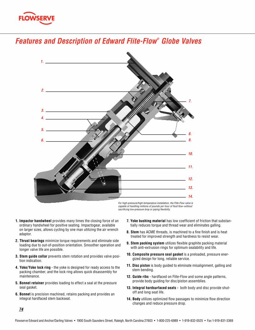
74
Flowserve Edward and Anchor/Darling Valves • 1900 South Saunders Street, Raleigh, North Carolina 27603 • 1-800-225-6989 • 1-919-832-0525 • Fax 1-919-831-3369
Features and Description of Edward Flite-Flow® Globe Valves
1. Impactor handwheel provides many times the closing force of an ordinary handwheel for positive seating. Impactogear, available on larger sizes, allows cycling by one man utilizing the air wrench adaptor.
2.Thrustbearings minimize torque requirements and eliminate side loading due to out-of-position orientation. Smoother operation and longer valve life are possible.
3.Stemguidecollar prevents stem rotation and provides valve posi-tion indication.
4.Yoke/Yokelockring - the yoke is designed for ready access to the packing chamber, and the lock ring allows quick disassembly for maintenance.
5. Bonnet retainer provides loading to effect a seal at the pressure seal gasket.
6. Bonnet is precision machined, retains packing and provides an integral hardfaced stem backseat.
7.Yokebushingmaterial has low coefficient of friction that substan-tially reduces torque and thread wear and eliminates galling.
8.Stem has ACME threads, is machined to a fine finish and is heat treated for improved strength and hardness to resist wear.
9.Stempackingsystem utilizes flexible graphite packing material with anti-extrusion rings for optimum sealability and life.
10.Compositepressuresealgasket is a preloaded, pressure ener-gized design for long, reliable service.
11. Disc piston is body guided to eliminate misalignment, galling and stem bending.
12.Guideribs - hardfaced on Flite-Flow and some angle patterns, provide body guiding for disc/piston assemblies.
13.Integralhardsurfacedseats- both body and disc provide shut-off and long seat life.
14.Body utilizes optimized flow passages to minimize flow direction changes and reduce pressure drop.
For high-pressure/high-temperature installation, the Flite-Flow valve is capable of handling millions of pounds per hour of fluid flow–without sacrificing low-pressure drop or piping flexibility.
1.
2.
3.
4.
5.
6.
7.
8.
9.
10.
11.
12.
13.
14.

flowserve.com
75
Flowserve Edward and Anchor/Darling Valves • 1900 South Saunders Street, Raleigh, North Carolina 27603 • 1-800-225-6989 • 1-919-832-0525 • Fax 1-919-831-3369
Special Application Valves
Flowserve - Edward Throttle ValvesEdward standard cast steel valves with the body-guided feature have excellent ability to handle flow at high-pressure differentials. However, for improved accuracy, cast globe and angle stop valves can be equipped with a special throttle disc. Disc shape provides good regulation over wide ranges of flow. When required, valves equipped with a throttle disc may also be ordered with a motor operator. Edward cast stop valves equipped with a throttle disc are identified by adding the suffix “K” to the standard valve figure number.
ComparisonCurvesofTypicalStandardDiscwithThrottleDisc
The standard stop valve disc gives rapid increases in flow for each increment of lift at low lifts and small increases in flow at higher lifts. This is not desirable in many applications where the valve is used for controlling flow rate. The conical projec-tion on the throttle disc gives straight line control at the lower lifts as long as it remains in the seat. Once the cone lifts entirely out of the seat, it permits high capacity at high lifts with only moderate pressure drop penalty.
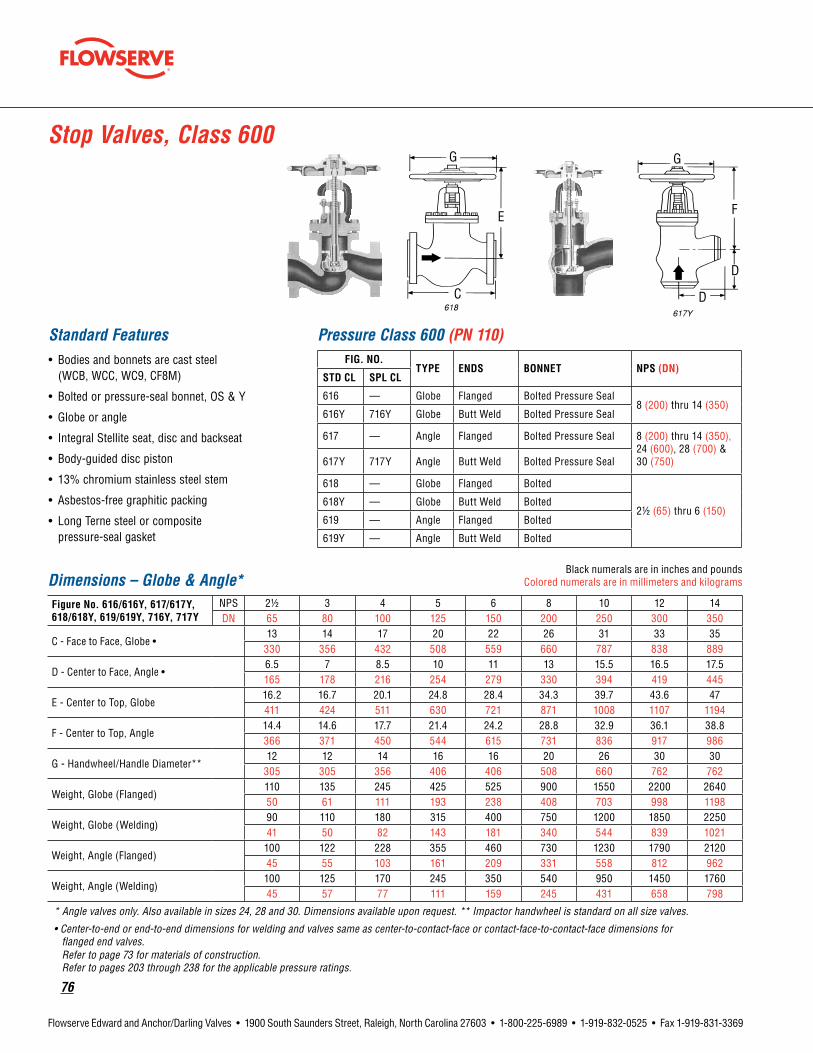
76
Flowserve Edward and Anchor/Darling Valves • 1900 South Saunders Street, Raleigh, North Carolina 27603 • 1-800-225-6989 • 1-919-832-0525 • Fax 1-919-831-3369
Stop Valves, Class 600
Standard Features• Bodies and bonnets are cast steel
(WCB, WCC, WC9, CF8M)
• Bolted or pressure-seal bonnet, OS & Y
• Globe or angle
• Integral Stellite seat, disc and backseat
• Body-guided disc piston
• 13% chromium stainless steel stem
• Asbestos-free graphitic packing
• Long Terne steel or composite pressure-seal gasket
Pressure Class 600 (PN 110)FIG.NO.
TYPE ENDS BONNET NPS(DN)STDCL SPLCL
616 — Globe Flanged Bolted Pressure Seal8 (200) thru 14 (350)
616Y 716Y Globe Butt Weld Bolted Pressure Seal
617 — Angle Flanged Bolted Pressure Seal 8 (200) thru 14 (350), 24 (600), 28 (700) & 30 (750)617Y 717Y Angle Butt Weld Bolted Pressure Seal
618 — Globe Flanged Bolted
21/2 (65) thru 6 (150)618Y — Globe Butt Weld Bolted
619 — Angle Flanged Bolted
619Y — Angle Butt Weld Bolted
Dimensions – Globe & Angle*Black numerals are in inches and pounds
Colored numerals are in millimeters and kilograms
FigureNo.616/616Y,617/617Y,618/618Y,619/619Y,716Y,717Y
NPS 21/2 3 4 5 6 8 10 12 14DN 65 80 100 125 150 200 250 300 350
C - Face to Face, Globe •13 14 17 20 22 26 31 33 35
330 356 432 508 559 660 787 838 889
D - Center to Face, Angle •6.5 7 8.5 10 11 13 15.5 16.5 17.5165 178 216 254 279 330 394 419 445
E - Center to Top, Globe16.2 16.7 20.1 24.8 28.4 34.3 39.7 43.6 47411 424 511 630 721 871 1008 1107 1194
F - Center to Top, Angle14.4 14.6 17.7 21.4 24.2 28.8 32.9 36.1 38.8366 371 450 544 615 731 836 917 986
G - Handwheel/Handle Diameter**12 12 14 16 16 20 26 30 30
305 305 356 406 406 508 660 762 762
Weight, Globe (Flanged)110 135 245 425 525 900 1550 2200 264050 61 111 193 238 408 703 998 1198
Weight, Globe (Welding)90 110 180 315 400 750 1200 1850 225041 50 82 143 181 340 544 839 1021
Weight, Angle (Flanged)100 122 228 355 460 730 1230 1790 212045 55 103 161 209 331 558 812 962
Weight, Angle (Welding)100 125 170 245 350 540 950 1450 176045 57 77 111 159 245 431 658 798
* Angle valves only. Also available in sizes 24, 28 and 30. Dimensions available upon request. ** Impactor handwheel is standard on all size valves.
• Center-to-end or end-to-end dimensions for welding and valves same as center-to-contact-face or contact-face-to-contact-face dimensions for flanged end valves. Refer to page 73 for materials of construction. Refer to pages 203 through 238 for the applicable pressure ratings.
D
E F
G
C
D
G

flowserve.com
77
Flowserve Edward and Anchor/Darling Valves • 1900 South Saunders Street, Raleigh, North Carolina 27603 • 1-800-225-6989 • 1-919-832-0525 • Fax 1-919-831-3369
Standard Features• Bodies and bonnets are cast steel
(WCB, WCC, WC9, CF8M)
• Pressure-seal bonnet, OS & Y
• Y Pattern
• Integral Stellite seat, disc and backseat
• Body-guided disc piston
• 13% chromium stainless steel stem
• Asbestos-free graphite packing
• Spiral-wound or composite pressure-seal gasket
Stop Valves, Class 600
Pressure Class 600 (PN 110)*Fig. No.
Type Ends Bonnet NPS(DN)STDCL SPLCL
614*** — Flite-Flow Flanged *Pressure Seal3 (80) thru 32 (800)
614Y 714Y Flite-Flow Butt Weld *Pressure Seal
* 3 and 4 bolted bonnet with asbestos-free spiral-wound gasket.
* Size 3 and 4 butt weld valves are Class 700.
Dimensions – Flite-Flow®Black numerals are in inches and pounds
Colored numerals are in millimeters and kilograms
FigureNo.614Y/714Y,614***NPS 3 4 6 8 10 12 14 16 20 24 26 28 32DN 80 100 150 200 250 300 250 400 500 600 650 700 800
A1 - End to End, (Welding)13 15.5 20 26 31 38 38 41 60 66 70 81.5 90
330 394 508 660 788 965 965 1041 1524 1676 1778 2070 2286
A2 - Face to Face, (Flanged) 16.75 21.25 29 33 39 45 45 52
* * * * *425 540 737 838 991 1143 1143 1321
E - Center to Top, (Open)17.5 21.5 28.5 34 42 49 49 74 71
* * * *445 546 724 864 1067 1245 1245 1880 1803
G - Handwheel Diameter12 14 16 20 26 30 30 48 48
* * * *305 356 406 508 660 762 762 1219 1219
Weight, (Welding)110 150 450 850 1400 2050 2050 5500 9200
* * * *50 68 204 385 635 930 930 2495 4173
Weight, (Flanged)150 240 570 1000 1800 2450 2550 6500
* * * * *68 109 259 454 816 1111 1157 2948
* Dimensions and information supplied upon request. ** Impactor handwheel standard on all Flite-Flow valves. *** Flanged valves are available in sizes 3 through 16. Refer to page 73 for materials of construction. Refer to pages 203 through 238 for the applicable pressure ratings.
G
A
E

78
Flowserve Edward and Anchor/Darling Valves • 1900 South Saunders Street, Raleigh, North Carolina 27603 • 1-800-225-6989 • 1-919-832-0525 • Fax 1-919-831-3369
Dimensions – Globe & Angle*Black numerals are in inches and pounds
Colored numerals are in millimeters and kilograms
FigureNo.604/604Y,605/605Y,606/606Y,607/607Y,706Y,707Y
NPS 21/2 3 4 5 6 8 10 12 14DN 65 80 100 125 150 200 250 300 350
C - Face to Face, Globe**13 14 17 20 22 26 31 33 35
330 356 432 508 559 660 787 838 889
D - Center to Face, Angle**6.5 7 8.5 10 11 13 15.5 16.5 17.5165 178 216 254 279 330 394 419 445
E - Center to Top, Globe16.2 16.7 20.1 24.8 28.4 34.3 39.7 43.6 47411 424 511 630 721 871 1008 1107 1194
F - Center to Top, Angle14.4 14.6 17.7 21.4 24.2 28.8 32.9 36.1 38.8366 371 450 544 615 731 836 917 986
G - Handwheel Diameter#12 12 14 16 16 20 26 30 30
305 305 356 406 406 508 660 762 762
H - Clearance for Equalizer8.7 8.5 10 9.6 11 11.8 13 13.7 15.7221 216 254 244 279 300 330 348 399
Weight, Globe (Flanged)110 135 220 425 540 960 1540 2200 268050 61 112 193 245 435 699 998 1216
Weight, Globe (Welding)84 110 185 335 410 750 1270 1850 225038 50 84 152 186 340 596 839 1021
Weight, Angle (Flanged)105 125 225 325 460 750 1200 1790 215048 57 102 147 209 340 544 812 975
Weight, Angle (Welding)80 90 168 245 350 560 950 1450 176036 41 76 111 159 254 431 667 798
* Angle valves only. Also available in sizes 24, 28 and 30. Dimensions available upon request. ** Center-to-end or end-to-end dimensions for welding and valves same as center to contact-face or contact-face-to-contact-face dimensions for flanged end valves. # Impactor handwheel is standard on all size valves. Refer to page 73 for materials of construction. Refer to pages 203 through 238 for the applicable pressure ratings.
Standard Features• Bodies and bonnets are cast steel
(WCB, WCC, WC9, CF8M)
• Bolted or pressure-seal bonnet OS & Y
• Globe or angle
• Integral Stellite seat, disc and backseat
• Body-guided disc piston
• 13% chromium stainless steel stem
• Asbestos-free graphitic packing
• Long terne# steel or composite pressure seal gasket
• Equipped with equalizer
Pressure Class 600 (PN 110)FIG.NO.
TYPE ENDS BONNET NPS(DN)STDCL SPLCL
604 — Globe Flanged Bolted
21/2 (65) thru 6 (150)604Y — Globe Butt Weld Bolted
605 — Angle Flanged Bolted
605Y — Angle Butt Weld Bolted
606 — Globe Flanged Pressure Seal8 (200) thru 14 (350)
606Y 706Y Globe Butt Weld Pressure Seal
607 — Angle Flanged Pressure Seal 8 (200) thru 14 (350), 24 (600), 28 (700) & 30 (750)607Y 707Y Angle Butt Weld Pressure Seal
Stop-Check (Non-Return) Valves, Class 600
D
E F
G
C
D
GH
flowserve.com
79
Flowserve Edward and Anchor/Darling Valves • 1900 South Saunders Street, Raleigh, North Carolina 27603 • 1-800-225-6989 • 1-919-832-0525 • Fax 1-919-831-3369
Stop-Check (Non-Return) Valves, Class 600
Standard Features• Bodies and bonnets are cast steel
(WCB, WCC, WC9, CF8M)
• Bolted or pressure-seal bonnet, OS & Y
• Y Pattern
• Integral Stellite seat, disc and backseat
• Body-guided disc piston
• 13% chromium stainless steel stem
• Asbestos-free graphitic packing
• Spiral wound or composite pressure seal gasket
• Equipped with equalizer
Pressure Class 600 (PN 110)*Fig. No.
Type Ends Bonnet NPS(DN)STDCL SPLCL
***602 — Flite-Flow Flanged Pressure Seal*3 (80) thru 32 (800)
602Y 702Y Flite-Flow Butt Weld Pressure Seal*
* Size 3 & 4 - Bolted bonnet with asbestos-free spiral-wound gasket.
* Size 3 & 4 Butt weld valves are Class 700.
Dimensions – Flite-Flow®Black numerals are in inches and pounds
Colored numerals are in millimeters and kilograms
FigureNo.602Y/702Y,***602NPS 3 4 6 8 10 12 14 16 20 24 26 28 32DN 80 100 150 200 250 300 250 400 500 600 650 700 800
A1 - End to End, (Welding)13 15.5 20 26 31 38 38 41 60 66 70 81.5 90
330 394 508 660 787 965 965 1041 1524 1676 1778 2070 2286
A2 - Face to Face, (Flanged)16.75 21.25 29 33 39 45 45 52
* * * * *425 540 737 838 991 1143 1143 1321
E - Center to Top, (Open)17.5 21.5 28.5 34 42 49 49 74 71
* * * *445 546 724 864 1067 1245 1245 1880 1803
G - Handwheel Diameter12 14 16 20 26 30 30 48 48
* * * *305 356 406 508 660 762 762 1219 1219
H - Equalizer Clearance7 9 10 12 13 14 14 22 24
* * * *178 229 254 305 330 356 356 559 610
Weight, (Welding)110 150 450 850 1400 2050 2050 5500 9200
* * * *50 68 204 385 635 930 930 2495 4173
Weight, (Flanged)150 240 570 1000 1800 2850 3100 6500 *
* * * *68 109 259 454 816 1293 1406 2948
* E, G and other dimensions and information supplied upon request. ** Impactor handwheel standard on all Flite-Flow valves.
*** Flanged valves available in sizes 3 thru 16. Refer to page 73 for materials of construction. Refer to pages 203 through 238 for the applicable pressure ratings.
A
E
GH

80
Flowserve Edward and Anchor/Darling Valves • 1900 South Saunders Street, Raleigh, North Carolina 27603 • 1-800-225-6989 • 1-919-832-0525 • Fax 1-919-831-3369
Stop Valves, Class 900
Standard Features• Bodies and bonnets are cast steel
(WCB, WCC, WC9, CF8M)
• Pressure-seal bonnet, OS & Y
• Y Pattern, globe and angle design
• Integral Stellite seat, disc and backseat
• Body-guided disc piston
• 13% chromium stainless steel stem
• Asbestos-free graphitic packing
• Yoke bushing thrust bearings size 5 and larger
Pressure Class 900 (PN 150)*Fig. No.
Type Ends NPS(DN)STDCL SPLCL
4016 — Globe Flanged3 (80) thru 14 (350)
4016Y 4316Y Globe Butt Weld
4017 — Angle Flanged3 (80) thru 24 (600)
4017Y 4317Y Angle Butt Weld
4014 Flite-Flow Flanged3 (80) thru 16 (400)
4014Y 4314Y Flite-Flow Butt Weld*
Size 3 and 4 Butt weld Flite-Flow valves are class 1100.
Dimensions – Globe & AngleBlack numerals are in inches and pounds
Colored numerals are in millimeters and kilograms
FigureNo.4016/4016Y,4017/4017Y,4316Y, 4317Y
NPS 3 4 5 6 8 10 12 14DN 80 100 125 150 200 250 300 350
A - End to End (Welding)15 18 22 24 29 33 38 40.5
381 457 559 610 737 838 965 1029
B - Center to Face (Welding)7.5 9 11 12 14.5 16.5 19 19190 229 279 305 368 419 483 483
C - Face to Face (Flanged)15 18 22 24 29 33 38 40.5
381 457 559 610 737 838 965 1029
D - Center to Face (Flanged)7.5 9 11 12 14.5 16.5 19 21.75190 229 279 305 368 419 483 552
E - Center to Top, Globe (Open)22.5 26.25 30.6 37 46 54.75 64.75 71.25572 667 777 940 1168 1391 1645 1810
F - Center to Top, Angle (Open)20.4 23.75 28.25 34.25 43.4 49.25 60 60518 603 718 870 1102 1251 1524 1524
G - Handwheel Diameter*16 16 20 20 28 28 36 36
406 406 508 508 711 711 914 914
Weight, Globe (Flanged)210 310 610 800 1570 2410 3700 460095 141 277 363 712 1093 1665 2086
Weight, Globe (Welding)175 235 500 620 1390 2300 3100 385079 107 227 281 630 1043 1395 1746
Weight, Angle (Flanged)206 284 540 710 1360 2103 3010 306093 129 245 322 612 946 1365 1388
Weight, Angle (Welding)150 210 410 552 1035 1690 2555 258068 95 185 250 466 761 1159 1170
* Impactor handwheel is standard on all valves. Refer to page 73 for materials of construction. Refer to pages 203 through 238 for the applicable pressure ratings.

flowserve.com
81
Flowserve Edward and Anchor/Darling Valves • 1900 South Saunders Street, Raleigh, North Carolina 27603 • 1-800-225-6989 • 1-919-832-0525 • Fax 1-919-831-3369
Stop Valves, Class 900
Dimensions – AngleBlack numerals are in inches and pounds
Colored numerals are in millimeters and kilograms
FigureNo.4017/4017Y,4317YNPS 16 18 20 24DN 400 450 500 600
B - Center to End (Welding)26 ** 32.5 39
660 825 991
F - Center to Top, Angle78.5 ** 95 1021994 2413 2591
G - Handwheel Diameter*48 ** 72 72
1219 1829 1829
Weight, Angle (Welding)4440 ** 8150 13,7502014 3697 6237
** Size 18 angle - available upon request.
Dimensions – Flite-Flow®
FigureNo.4014/4014Y,4314YNPS 3 4 6 8 10 12 14 16DN 80 100 150 200 250 300 350 400
A1 - End to End (Welding)17 18.5 20 26 31 38 38 44.5
432 479 508 660 787 965 965 1130
A2 - Face to Face (Flanged)22.25 23.75 30 38 44 50 51 58565 603 762 965 1118 1270 1295 1473
E - Center to Top (Open)20 25 35 44 51 60 60 73
508 635 889 1118 1295 1524 1524 1854
G - Handwheel Diameter*16 16 20 28 28 36 36 48
406 406 508 711 711 914 914 1219
Weight (Welding)190 275 550 1150 2100 3400 3400 555086 125 249 522 953 1542 1542 2517
Weight (Flanged)250 370 775 1550 2650 4150 4550 6950113 168 352 703 1202 1882 2064 3152
Note: Size 3 and 4 Buttweld Class 900 Flite-Flow Valves are Class 1100. *Impactor handwheel is standard on all valves. Refer to page 73 for materials of construction. Refer to pages 203 through 238 for the applicable pressure ratings.

82
Flowserve Edward and Anchor/Darling Valves • 1900 South Saunders Street, Raleigh, North Carolina 27603 • 1-800-225-6989 • 1-919-832-0525 • Fax 1-919-831-3369
Stop-Check (Non-Return) Valves, Class 900
Standard Features• Bodies and bonnets are cast steel
(WCB, WCC, WC9, CF8M)
• Pressure-seal Bonnet, OS & Y
• Y Pattern, globe and angle design
• Integral Stellite seat, disc and backseat
• Body-guided disc piston
• 13% chromium stainless steel stem
• Asbestos-free graphitic packing
• Equipped with equalizer
• Yoke bushing thrust bearings
Pressure Class 900 (PN 150)*FIG.NO.
TYPE ENDS NPS(DN)STDCL SPLCL
4006 — Globe Flanged3 (80) thru 14 (350)
4006Y 4306Y Globe Butt Weld
4007 — Angle Flanged3 (80) thru 24 (600)
4007Y 4307Y Angle Butt Weld
4002 — Flite-Flow Flanged3 (80) thru 16 (400)
4002Y 4302Y Flite-Flow Butt Weld*
* Size 3 and 4 Butt weld Flite-Flow valves are Class 1100.
Dimensions – Globe & AngleBlack numerals are in inches and pounds
Colored numerals are in millimeters and kilograms
FigureNo.4006/4006Y,4007/4007Y,4306Y,4307Y
NPS 3 4 5 6 8 10 12 14DN 80 100 125 150 200 250 300 350
A - End to End (Welding)15 18 22 24 29 33 38 40.5
381 457 559 610 737 838 965 1029
B - Center to End (Welding)7.5 9 11 12 14.5 16.5 19 19190 22 279 305 368 419 483 483
C - Face to Face (Flanged)15 18 22 24 29 33 38 40.5
381 457 559 610 737 838 965 1029
D - Center to Face (Flanged)7.5 9 11 12 14.5 16.5 19 21.75190 229 279 305 368 419 483 552
E - Center to Top, Globe (Open)22.5 26.25 30.63 37 46 54.75 64.75 71.25572 667 778 940 1168 1391 1645 1810
F - Center to Top, Angle (Open)20.38 23.75 28.25 34.25 43.38 49.25 60 62.75518 603 718 870 1102 1251 1524 1594
G - Handwheel Diameter*16 16 20 20 28 28 36 36
406 406 508 508 711 711 914 914
H - Clearance for Equalizer7.5 7.63 9.75 10.75 12.5 12.88 14.75 17.38190 194 248 273 318 327 375 441
Weight, Globe (Flanged)220 314 615 800 1570 2425 3700 4600100 142 279 363 712 1100 1665 2087
Weight, Globe (Welding)175 245 500 642 1400 2300 3100 475079 111 227 291 635 1043 1406 2155
Weight, Angle (Flanged)206 284 540 690 1360 2103 3010 306093 129 245 313 617 954 1365 1388
Weight, Angle (Welding)150 215 410 552 1035 1600 2555 258068 98 186 250 469 725 1159 1170
* Impactor handwheel is standard on all valves. Refer to page 73 for materials of construction. Refer to pages 203 through 238 for the applicable pressure ratings.
flowserve.com
83
Flowserve Edward and Anchor/Darling Valves • 1900 South Saunders Street, Raleigh, North Carolina 27603 • 1-800-225-6989 • 1-919-832-0525 • Fax 1-919-831-3369
Stop-Check (Non-Return) Valves, Class 900
Dimensions – AngleBlack numerals are in inches and pounds
Colored numerals are in millimeters and kilograms
FigureNo.4007/4007Y,4307YNPS 16 18 20 24DN 400 450 500 600
B - Center to End (Welding)26
**32.5 39
660 825 991
F - Center to Top, Angle78.5
**95 102
1994 2413 2591
G - Handwheel Diameter*48
**72 72
1219 1829 1829
H - Clearance for Equalizer20
**21.5 30
50.8 546 762
Weight, Angle (Welding)4960
**8150 13,750
2250 3697 6237** Size 18" Angle - Available upon request.
Dimensions – Flite-Flow
FigureNo.4002/4002Y,4302YNPS 3 4 6 8 10 12 14 16DN 80 100 150 200 250 300 350 400
A1 - End to End (Welding)17 18.5 20 26 31 38 38 44.5
432 470 508 660 787 965 965 1130
A2 - Face to Face (Flanged)22.25 23.75 30 38 44 50 51 58565 603 762 965 1118 1270 1295 1473
E - Center to Top (Open)20 25 35 44 51 60 60 73
508 635 889 1118 1295 1524 1524 1854
G - Handwheel Diameter*16 16 20 28 28 36 36 48
406 406 508 711 711 914 914 1219
H - Equalizer Clearance9 9.3 10 12.5 16 15 15 25.75
229 236 254 318 406 381 381 654
Weight (Welding)190 275 555 1150 2100 3400 3400 555086 125 252 522 953 1542 1542 2517
Weight (Flanged)250 370 775 1550 2650 4150 4550 6950113 168 352 703 1202 1882 2064 3153
Note: Size 3 and 4 Buttweld Class 900 Flite-Flow valves are Class 1100. * Impactor handwheel is standard on all valves. Refer to page 73 for materials of construction. Refer to pages 203 through 238 for the applicable pressure ratings.

84
Flowserve Edward and Anchor/Darling Valves • 1900 South Saunders Street, Raleigh, North Carolina 27603 • 1-800-225-6989 • 1-919-832-0525 • Fax 1-919-831-3369
Stop Valves, Class 1500
Standard Features• Bodies and bonnets are cast steel
(WCB, WCC, WC9, CF8M)
• Pressure-seal bonnet, OS & Y
• Y Pattern, globe and angle design
• Integral Stellite seats and backseat
• Body-guided disc piston
• 13% chromium stainless steel stem
• Asbestos-free graphitic packing
• Yoke bushing thrust bearings size 5 and larger
Pressure Class 1500 (PN 260)*Fig. No.
Type Ends NPS(DN)STDCL SPLCL
7514Y 2014Y Flite-Flow Butt Weld* 3 (80) thru 24 (600)
7516 — Globe Flanged21/2 (65) thru 14 (350)
7516Y 2016Y Globe Butt Weld
7517 — Angle Flanged21/2 (65) thru 24 (600)
7517Y 2017Y Angle Butt Weld
Dimensions – Globe & AngleBlack numerals are in inches and pounds
Colored numerals are in millimeters and kilograms
FigureNo.7516/7516Y, 2016Y7517/7517Y,2017Y
NPS 21/2 3 4 5 6 8 10 12 14DN 65 80 100 125 150 200 250 300 350
A - End to End (Welding)13 15 18 22 24 29 33 38 40.5
330 381 457 559 610 737 838 965 1029
B - Center to End (Welding)6.5 7.5 9 11 12 14.5 16.5 19 20.25165 190 229 279 305 368 419 483 514
C - End to End (Flanged)16.5 18.5 21.5 26.5 27.75 32.75 39 44.5 49.5419 470 546 673 705 832 991 1130 1257
D - Center to End (Flanged)8.25 9.25 10.75 13.25 13.88 16.38 19.5 22.25 24.75210 235 273 337 353 416 495 565 629
E - Center to Top, Globe (Open)19.25 22.5 26.25 30.63 36.5 48.75 59.5 70 70489 572 667 778 927 1238 1511 1778 1778
F - Center to Top, Angle (Open)18 20.4 23.75 28.25 34.75 45.75 56 66.3 66.75
457 518 603 718 883 1162 1422 1684 1695
G - Handwheel Diameter*14 16 16 20 20 28 36 36 48
356 406 406 508 508 711 914 914 1219
Weight, Globe (Flanged)167 260 385 760 960 1800 3150 4910 590076 118 175 345 435 816 1429 2227 2676
Weight, Globe (Welding)90 175 270 525 700 1620 2600 3710 485041 79 122 238 317 735 1179 1683 2200
Weight, Angle (Flanged)153 230 330 730 865 1580 2780 4100 485069 104 150 331 392 717 1261 1860 2200
Weight, Angle (Welding)80 150 255 510 670 1250 2200 2900 380036 68 116 231 304 567 998 1315 1724
*Impactor handle is standard on size 21/2 Globe and Angle valves. *Impactor handwheel is standard on all other size Globe and Angle valves and all Flite-Flow valves. *Impactogear is available on size 8 and larger Globe, Angle and Flite-Flow valves. Refer to page 73 for materials of construction. Refer to pages 203 through 238 for the applicable pressure ratings.

flowserve.com
85
Flowserve Edward and Anchor/Darling Valves • 1900 South Saunders Street, Raleigh, North Carolina 27603 • 1-800-225-6989 • 1-919-832-0525 • Fax 1-919-831-3369
Stop Valves, Class 1500
Dimensions – Globe & AngleBlack numerals are in inches and pounds
Colored numerals are in millimeters and kilograms
FigureNo.7517/7517Y,2017YNPS 16 18 20 24DN 400 450 500 600
B - Center to End (Welding)23.5 23.5 28.5 35.5597 597 724 902
F - Center to Top, Angle77.5 77.5 84 1031969 1969 2134 2616
G - Handwheel Diameter*48 48 72 72
1219 1219 1829 1829
Weight, Angle (Welding)6600 6800 9500 16,2002994 3084 4309 7348
Dimensions – Flite-Flow®
FigureNo.7514Y/2014YNPS 3 4 6 8 10 12 14 16 18 20 24DN 80 100 150 200 250 300 350 400 450 500 600
A - End to End (Welding)17 18.5 27.75 30 36.25 43 41 54 63 54.5 59.5
432 470 705 762 921 1092 1041 1372 1600 1384 1511
E - Center to Top (Open)20 25 34.25 45 53.5 60.75 60.75 78.5 78.5 96 96
508 635 870 1143 1359 1543 1543 1994 1994 2438 2438
G - Handwheel Diameter*16 16 20 28 36 36 36 48 48 72 72
406 406 508 711 914 914 914 1219 1219 1829 1829
Weight (Welding)210 300 700 1550 2725 4220 4300 7650 8390 10,500 16,80095 136 318 702 1236 1914 1950 3470 3806 4763 7620
Notes: Size 3 and 4 Buttweld Class 1500 Flite-Flow valves are Class 1800.
*Impactor handle is standard on size 21/2 Globe and Angle valves. *Impactor handwheel is standard on all other size Globe and Angle valves and all Flite-Flow valves. *Impactogear is available on size 8 and larger Globe, Angle and Flite-Flow valves. Refer to page 73 for materials of construction. Refer to pages 203 through 238 for the applicable pressure ratings.

86
Flowserve Edward and Anchor/Darling Valves • 1900 South Saunders Street, Raleigh, North Carolina 27603 • 1-800-225-6989 • 1-919-832-0525 • Fax 1-919-831-3369
Stop-Check (Non-Return) Valves, Class 1500
Standard Features• Bodies and bonnets are cast steel
(WCB, WCC, WC9, CF8M)
• Pressure-seal bonnet, OS & Y
• Y Pattern, globe or angle design
• Integral Stellite seats and backseat
• Body-guided disc piston
• 13% chromium stainless steel stem
• Asbestos-free graphitic packing
• Equipped with equalizer
• Yoke bushing thrust bearings size 5 and larger
Pressure Class 1500 (PN 260)*FIG.NO.
TYPE ENDS NPS(DN)STDCL SPLCL
7502Y 2002Y Flite-Flow Butt Weld* 3 (80) thru 24 (600)
7506 — Globe Flanged21/2 (65) thru 14 (350)
7506Y 2006Y Globe Butt Weld
7507 — Angle Flanged21/2 (65) thru 24 (600)
7507Y 2007Y Angle Butt Weld
* Size 3 and 4 Buttweld Flite-Flow valves are Class 1800.
Dimensions – Globe & AngleBlack numerals are in inches and pounds
Colored numerals are in millimeters and kilograms
FigureNo.7506/7506Y,7507/7507Y,2006Y,2007Y
NPS 21/2 3 4 5 6 8 10 12 14DN 65 80 100 125 150 200 250 300 350
A - End to End (Welding)13 15 18 22 24 29 33 38 40.5
330 381 457 559 610 737 838 965 1029
B - Center to End (Welding)6.5 7.5 9 11 12 14.5 16.5 19 20.25165 190 229 279 305 368 419 483 514
C - Face to Face (Flanged)16.5 18.5 21.5 26.5 27.75 32.75 39 44.5 49.5419 470 546 673 705 832 991 1130 1257
D - Center to Face (Flanged)8.25 9.25 10.75 13.25 13.88 16.38 19.5 22.25 24.75210 235 273 337 353 416 495 565 628
E - Center to Top, Globe19.25 22.5 26.25 30.63 36.5 48.75 59.5 70 70489 572 667 778 927 1238 1511 1778 1778
F - Center to Top, Angle18 20.38 23.75 28.25 34.75 45.75 56 66.3 66.75
457 518 603 718 883 1162 1422 1684 1695
G - Handwheel Diameter*14 16 16 20 20 28 36 36 48
356 406 406 508 508 711 914 914 1219
H - Clearance for Equalizer6.75 7.75 7.75 10 10.75 12.75 14 15 17.38171 197 197 254 273 324 356 381 441
Weight, Globe (Flanged)167 270 385 770 960 1800 3150 4910 590076 122 175 349 435 816 1429 2227 2676
Weight, Globe (Welding)90 180 270 570 710 1470 2600 3710 485041 82 122 258 322 667 1179 1683 2200
Weight, Angle (Flanged)153 230 330 730 865 1580 2780 4100 485069 104 149 331 392 717 1261 1860 2200
Weight, Angle (Welding)77 160 255 510 585 1250 2200 2900 380035 73 116 231 265 567 998 1315 1724
* Impactor handle is standard on size 21/2 Globe and Angle valves. *Impactor handwheel is standard on all other size Globe and Angle valves and all Flite-Flow valves. *Impactogear is available on size 8 and larger Globe, Angle and Flite-Flow valves. Refer to page 73 for materials of construction. Refer to pages 203 through 238 for the applicable pressure ratings.
flowserve.com
87
Flowserve Edward and Anchor/Darling Valves • 1900 South Saunders Street, Raleigh, North Carolina 27603 • 1-800-225-6989 • 1-919-832-0525 • Fax 1-919-831-3369
Stop-Check (Non-Return) Valves, Class 1500
Dimensions – AngleBlack numerals are in inches and pounds
Colored numerals are in millimeters and kilograms
FigureNo.7507/7507Y,2007YNPS 16 18 20 24DN 400 450 500 600
B - Center to End (Welding)23.5 23.5 28.5 35.5597 597 724 902
F - Center to Top, Angle77.5 77.5 84 1031969 1969 2134 2616
G - Handwheel Diameter*48 48 72 72
1219 1219 1829 1829
H - Clearance for Equalizer19.5 19.5 23 28.5495 495 584 724
Weight, Angle (Welding)6600 6800 9500 16,2002994 3084 4309 7348
Dimensions – Flite-Flow
FigureNo.7502Y,2002YNPS 3 4 6 8 10 12 14 16 18 20 24DN 80 100 150 200 250 300 350 400 450 500 600
A - End to End (Welding)17 18.5 27.75 30 36.25 43 41 54 63 54.5 59.5
432 470 705 762 921 1092 1041 1372 1600 1384 1511
E - Center to Top20 25 34.25 45 53.5 60.75 60.75 78.5 78.5 96 96
508 635 870 1143 1359 1543 1543 1994 1994 2438 2438
G - Handwheel Diameter*16 16 20 28 36 36 36 48 48 72 72
406 406 508 711 914 914 914 1219 1219 1829 1829
H - Equalizer Clearance9 10 10.75 12.75 15.75 16.5 16.5 19.5 19.5 28 28
229 254 273 324 400 419 419 495 495 711 711
Weight (Welding)210 300 720 1600 2820 4260 4280 8450 8400 10,500 11,50095 136 327 726 1279 1932 1941 3833 3810 4763 5216
Note: Size 3 and 4 Buttweld Class 1500 Flite-Flow valves are Class 1800.
*Impactor handle is standard on size 21/2 Globe and Angle valves. *Impactor handwheel is standard on all other size Globe and Angle valves and all Flite-Flow valves. *Impactogear is available on size 8 and larger Globe, Angle and Flite-Flow valves. Refer to page 73 for materials of construction. Refer to pages 203 through 238 for the applicable pressure ratings.

88
Flowserve Edward and Anchor/Darling Valves • 1900 South Saunders Street, Raleigh, North Carolina 27603 • 1-800-225-6989 • 1-919-832-0525 • Fax 1-919-831-3369
Pageintentionallyleftblank

flowserve.com
89
Flowserve Edward and Anchor/Darling Valves • 1900 South Saunders Street, Raleigh, North Carolina 27603 • 1-800-225-6989 • 1-919-832-0525 • Fax 1-919-831-3369
Anchor/DarlingGlobeValves

90
Flowserve Edward and Anchor/Darling Valves • 1900 South Saunders Street, Raleigh, North Carolina 27603 • 1-800-225-6989 • 1-919-832-0525 • Fax 1-919-831-3369
Features and Description of Anchor/Darling 800 Series Globe Valves
1.Oversizedstem provides stronger disc-to-stem connection and reduces packing wear through increased stiffness.
2.Graphitestem packing provides better sealing and longer packing life.
3.ADVansealpressure sealing system eliminates leakage, reduces maintenance and is more cost effective.
4.Seatring is solid, hardened material (Stellite or non-Cobalt) and is fully shouldered and brazed in place.
5. Disc is body guided and solid hardened material (Stellite or non-Cobalt).
6.Machinedbackseat provides additional packing protection.
7.Investmentcastbody produces a smooth flow transition, minimizes flow turbulence resulting in higher Cv’s. Pressure seal bonnet eliminates leakage.
1.
2.
3.
4.
6.
7.
5.

flowserve.com
91
Flowserve Edward and Anchor/Darling Valves • 1900 South Saunders Street, Raleigh, North Carolina 27603 • 1-800-225-6989 • 1-919-832-0525 • Fax 1-919-831-3369
Parts Specification List for Anchor/Darling 800 Series Globe Valves
Standard Features• Available body material
SA216-WCB SA351-CF8M
• Investment cast for smooth flow
• Rising stem design
• One-piece body and bonnet
Anchor/Darling800SeriesglobevalvesfornuclearservicearenormallyfurnishedinClass800.Otherinterpolatedpressureclasses are also available on application.
Parts shown are not applicable to all 800 Series valves. Construction and materials for nuclear valves may vary depending upon customer design specifications. For a complete, accurate and itemized description of a particular valve, contact your local Flowserve valves sales representative.
Description ASME/ASTMNo. ASME/ASTMNo.Body SA216-WCB SA351-CF8MStem A564-630-1075 A564-630-1075Disc SA564-630-1075 SA564-630-1075Seat A276-S21800A A276-S21800AEndRings Braided Graphite Braided GraphitePackingRings Grafoil GrafoilGlandRetainer A564-630-1075 A564-630-1075GlandAdjustingScrew AISI 300 AISI 300YokeBushing B21-C464-H02 B21-C464-H02Handwheel A351-CF8M A351-CF8MStemNut A194-2H A194-2H

92
Flowserve Edward and Anchor/Darling Valves • 1900 South Saunders Street, Raleigh, North Carolina 27603 • 1-800-225-6989 • 1-919-832-0525 • Fax 1-919-831-3369
800 Series Stop Valves – T Pattern, Class 800
Features• Pressure Class 800 (Intermediate)
(WCB, CF8M)
• Investment cast body
• Body-guided solid hard-faced disc; non-cobalt standard
• Non-cobalt seat ring; standard
• Oversized stem
• ADVanseal® pressure seal
• Machined backseat
Dimensions – GlobeBlack numerals are in inches and pounds
Colored numerals are in millimeters and kilograms
FigureNo.UGB24S/UGB24UNPS 1/2 3/4 1 11/2 2DN 15 20 25 40 50
A3.7 3.7 4.8 6.3 7.094 94 122 160 178
D3.0 3.0 4.0 6.0 9.076 76 102 152 229
F5.4 5.4 6.9 8.3 9.4137 137 175 211 239
G5.8 5.8 7.4 9.0 10.4147 147 188 229 264
Weight Approx (lbs.)4.0 4.0 6.0 13.0 20.01.8 1.8 2.7 5.9 9.1
Cv 4.5 4.5 8 22 36
Refer to page 91 for materials of construction. Refer to pages 203 through 238 for the applicable pressure ratings.
Pressure Class 800 (PN 130)Fig. No. Type Ends NPS(DN)
UGB24S Globe Socket Weld 1/2 (15) thru 2 (50)
UGB24U Globe Butt Weld 1/2 (15) thru 2 (50)
D
F
A
G

flowserve.com
93
Flowserve Edward and Anchor/Darling Valves • 1900 South Saunders Street, Raleigh, North Carolina 27603 • 1-800-225-6989 • 1-919-832-0525 • Fax 1-919-831-3369
800 Series Stop Valves – T Pattern, Class 800
Features• Pressure Class 800 (Intermediate)
(WCB, CF8M)
• Investment cast body
• ADVanseal® body-bonnet sealing
• Secondary stem seal
- Backseat
- Stem packing
• Long bellows life
- Per MSS-SP-117
- 300 SS Bellows material
• Non-rotating stem
Dimensions – GlobeBlack numerals are in inches and pounds
Colored numerals are in millimeters and kilograms
FigureNo.UGB24S/UGB24UNPS 1/2 3/4 1 2DN 15 20 25 50
A 4.4 4.4 4.4 7D 4 4 4 9F 11.6 11.6 11.6 17.4G 12.1 12.1 12.1 18Weight Approx (lbs.) 11 11 11 35Cv 4 7 8 22
Refer to page 91 for materials of construction. Refer to pages 203 through 238 for the applicable pressure ratings.
Pressure Class 800 (PN 130)Fig. No. Type Ends NPS(DN)
UBG245 Globe Socket Weld 1/2 (15) thru 2 (50)
UBG24U Globe Butt Weld 1/2 (15) thru 2 (50)

94
Flowserve Edward and Anchor/Darling Valves • 1900 South Saunders Street, Raleigh, North Carolina 27603 • 1-800-225-6989 • 1-919-832-0525 • Fax 1-919-831-3369
Features and Description of 1878 Series Globe Valve
Standard Valve Features1.Aone-piecerugged, low-profile,
precision cast body/yoke assembly, manufactured using the latest investment casting techniques, offering smooth flow passages, not available with forged body valves.
2.Fourdistinctdiscstyles are offered either from the factory or easily field- converted from customer inventory.
A. Quick-open plug type
B. Parabolic
C. Cage type
A circular plate below the handwheel nut indicates the type of disc.
3.Asturdyself-aligningglandflange ensures positive loading of the packing and sealing integrity.
4.Expandedgraphitepacking with braided graphite end rings is standard. Live loaded packing is available as an option.
5.Largepackingglandbolts provide positive sealing and are easily removed for service.
6.TheT-handle is made of stainless steel and can be locked open or closed, if necessary. The 2" full ported valves use an impactor T-handle.
7.Alarge-diameterupperstem is utilized to provide ease of operation and is everlubed to minimize friction.
8. A stem clamp couples the rotating upper stem with the non-rotating lower stem and also serves as a position indicator.
9.Thelowernon-rotatingstem provides greater packing longevity than valves using rotating stems and has a T-head design, allowing ease of disc removal. Other competitive valves offering a stem-disc assembly are more costly and difficult to service.
10.Theseatring is non-Cobalt material that is furnace blazed into the body using a high-temperature nickel alloy. The disc is non-Cobalt material and is fully body-guided for proper seat alignment. Optional Cobalt-based seat and disc materials are available on special order.
6.
7.
8.
9.
5.
3.
4.
2.
1.
10.

flowserve.com
95
Flowserve Edward and Anchor/Darling Valves • 1900 South Saunders Street, Raleigh, North Carolina 27603 • 1-800-225-6989 • 1-919-832-0525 • Fax 1-919-831-3369
Parts Specification List for Anchor/Darling 1878 Series Globe ValvesStandard Features• Available body material
SA216-WCB SA351-CF8M
• Investment cast for smooth flow
• Integrated body and bonnet
• T and Y patterns
• Integrated body and bonnet
Anchor/Darling1878Seriesglobevalvesfornuclearservicearenormallyfurnishedin Class 1878. Other interpolated pressure classes are also available on application.
Parts shown are not applicable to all 1878 Series valves. Construction and materials for nuclear valves may vary depending upon customer design specifications. For a complete, accurate and itemized description of a particular valve, contact your local Flowserve valves sales representative.
Description ASME/ASTMNo. ASME/ASTMNo.Body SA216-WCB SA351-CF8MStem A564-630-1075 A564-630-1075Disc A747-CB7-CU1-H1100 A747-CB7-CU1-H1100Seat A276-S21800A A276-S21800AEndRings Braided Graphite Braided GraphitePackingRings Grafoil GrafoilGland A351-CF8M A351-CF8MGlandAdjustingScrew A564-630-1075 A564-630-1075YokeBushing B21-C464-H02 B21-C464-H02Handle A351-CF8M A351-CF8MStemNut A1S1 300 A1S1 300

96
Flowserve Edward and Anchor/Darling Valves • 1900 South Saunders Street, Raleigh, North Carolina 27603 • 1-800-225-6989 • 1-919-832-0525 • Fax 1-919-831-3369
Series 1878 Stop Valves, Class 1878
Features• Pressure Class 1878 (Intermediate)
(WCB, CF8M)
• One-piece investment cast body/yoke
• T-head stem for easy changeout of disc
• Four disc styles:
– Quick Opening
– Equal Percent
– Linear
– Resilient
• Bore-guided disc
• Non-rotating stem
• Ease of maintenance
• Graphite packing standard
• Removable threaded backseat or loose backseat
• Non-cobalt seating standard
• Integral position indicator
Pressure Class 1878 (PN 325)Fig. No. Type Ends NPS(DN)
NGB24S Globe Socket Weld 1/2 (15) thru 2 (50)
NGB24U Globe Butt Weld 1/2 (15) thru 2 (50)
Dimensions – GlobeBlack numerals are in inches and pounds
Colored numerals are in millimeters and kilograms
FigureNo.NGB24S/NGB24UNPS 1/2 3/4 1 11/2 2* 2DN 15 20 25 40 50 50
A5.5 5.5 5.5 7.0 8.5 8.5140 140 140 178 216 216
B10.8 10.8 10.8 13.7 13.7 16.6274 274 274 348 348 422
C11.5 11.5 11.5 14.7 14.7 17.8292 292 292 373 373 452
Weight Approx (lbs.)16 16 16 33 35 557.3 7.3 7.3 15.0 15.9 25
Cv** 7 8 8 24 24 38
* Reduced ports ** Quick open – Flow under disc Refer to page 95 for materials of construction. Refer to pages 203 through 238 for the applicable pressure ratings.
12
B
A
C

flowserve.com
97
Flowserve Edward and Anchor/Darling Valves • 1900 South Saunders Street, Raleigh, North Carolina 27603 • 1-800-225-6989 • 1-919-832-0525 • Fax 1-919-831-3369
• Non-rotating stem
• Ease of maintenance
• Graphite packing standard
• Removable threaded backseat or loose backseat
• Non-cobalt seating standard
• Integral position indicator
Features• Pressure Class 1878 (Intermediate)
(WCB, CF8M)
• One-piece investment cast body/yoke
• Four disc styles:
– Quick Opening
– Equal Percent
– Linear
– Resilient
• T-head stem for easy changeout of disc
• Bore-guided disc
• Integral position indicator
• Non-rotating stem
• Ease of maintenance
• Graphite packing standard
• Removable threaded backseat or loose backseat
• Non-cobalt seating standard
Series 1878 Stop Valves, Class 1878
Dimensions – GlobeBlack numerals are in inches and pounds
Colored numerals are in millimeters and kilograms
FigureNo.NYG34S/NYG34UNPS 1/2 3/4 1 11/2 2* 2DN 15 20 25 40 50 50
A5.5 5.5 5.5 7.0 8.5 8.5140 140 140 178 216 216
B11.3 11.3 11.3 14.3 14.3 17.3274 274 224 348 348 422
C11.9 11.9 11.9 15.3 15.3 18.5292 292 292 373 373 452
Weight Approx (lbs.)16 16 16 33 35 557.3 7.3 7.3 15 15.9 25
Cv** 14 16 16 48 48 76
* Reduced ports ** Quick open – Flow under disc Refer to page 95 for materials of construction. Refer to pages 203 through 238 for the applicable pressure ratings.
Pressure Class 1878 (PN 260)Fig. No. Type Ends NPS(DN)
NYG34S Y Globe Socket Weld 1/2 (15) thru 2 (50)
NYG34U Y Globe Butt Weld 1/2 (15) thru 2 (50)
12
B
A
C
98
Flowserve Edward and Anchor/Darling Valves • 1900 South Saunders Street, Raleigh, North Carolina 27603 • 1-800-225-6989 • 1-919-832-0525 • Fax 1-919-831-3369
Features• Pressure Class 1878 (Intermediate)
(WCB, CF8M)
• Investment cast body
• ADVanseal® body-bonnet sealing
• Secondary stem seal:
– Backseat
– Stem packing
• Long bellows life
– Per MSS-SP-117
• Non-rotating stem
• Quick-opening disc
• Ease of maintenance
– No welding design
– Rapid Change Kit
• Non-cobalt seating standard
Series 1878 Stop Valves – Y Pattern Bellows Seal, Class 1878
Rapid Change KitThe Rapid Change Kit includes trim parts, the ADVanseal® Pressure Seal Gasket, bellows and disc assembly, and is offered as a means for keeping the time to repair or refurbish trim components to a minimum and thereby help to minimize exposure time of maintenance personnel.
Rapid Change Kit
Pressure Class 1878 (PN 260)Fig. No. Type Ends NPS(DN)
NBG34S Globe Socket Weld 1/2 (15) thru 1 (25)
NBG34U Globe Butt Weld 1/2 (15) thru 1 (25)
Dimensions – Globe Black numerals are in inches and poundsColored numerals are in millimeters and kilograms
FigureNo.NBG34S/NBG34UNPS 1/2 3/4 1DN 15 20 25
A5.5 5.5 5.5140 140 140
B13.8 13.8 13.8351 351 351
C14.1 14.1 14.1358 358 358
Weight Approx (lbs.)21 21 219.5 9.5 9.5
Cv 8 9 9
Other sizes available upon request. Refer to page 95 for materials of construction. Refer to pages 203 through 238 for the applicable pressure ratings.
10
B
A
C
Also available in series 800.

flowserve.com
99
Flowserve Edward and Anchor/Darling Valves • 1900 South Saunders Street, Raleigh, North Carolina 27603 • 1-800-225-6989 • 1-919-832-0525 • Fax 1-919-831-3369
Series 1878 Instrument Valves – T Pattern, Class 1878
Features• Seat is cold-formed into body recess
• Bellows is two-ply Inconel 625 for increased strength and cycle life (per MSS-SP-117)
• Secondary packing seal provides backup sealing in case of bellows leakage
• Bonnet is threaded and seal welded to body to eliminate leak path
• Yoke adapter is equipped with bearings for easy operation at high pressure
• Available sizes – 1/2", 3/4" and 1"
• Weight – 5 1/2 pounds
• CV – 1
Pressure Class 1878 (PN 260)Fig. No. Type Ends NPS(DN)
NGI29S Instrument Globe Socket Weld 1/2 (15) thru 1 (25)
NGI29U Instrument Globe Butt Weld 1/2 (15) thru 1 (25)
Consult your Flowserve sales representative for materials of construction. Refer to pages 203 through 238 for the applicable pressure ratings.

100
Flowserve Edward and Anchor/Darling Valves • 1900 South Saunders Street, Raleigh, North Carolina 27603 • 1-800-225-6989 • 1-919-832-0525 • Fax 1-919-831-3369
Features and Description of Flowserve Anchor/Darling Globe Valves
Horizontal Globe Angle GlobeY GlobeY Angle Globe
FourBodyTypes
Various body types are offered to provide the piping designer greater flexibility. The Y globe and horizontal globe are normally used in horizontal pipelines. The angle globe is normally used in lieu of an elbow where flow control is necessary and when flow is upward in the vertical piping leg. The Y angle globe is normally used in lieu of an elbow where flow control is necessary and when flow is toward the valve in the horizontal piping leg.
1.Fullbodyguides ensure correct seat alignment.
2.Plugskirt prevents plug cocking even under turbulent flow conditions.
3. Differential mating angles between plug and seat ring ensure tight seal with low seating force.
4.Swivelplug ensures proper seat alignment and tight seal.
5. Cast bodies permit the internal flow passage to be designed with large radius curves. This provides smooth transitions and reduces damaging turbulence, which is unavoidable in bodies of forged and fabricated designs.
1. 2.
4. 5.
3.

flowserve.com
101
Flowserve Edward and Anchor/Darling Valves • 1900 South Saunders Street, Raleigh, North Carolina 27603 • 1-800-225-6989 • 1-919-832-0525 • Fax 1-919-831-3369
Standard Plug Cage Plug Parabolic Plug
Flowserve globe valves are easily adapted to power actuation. Electric motor, pneumatic and hydraulic units are commonly supplied, but custom designed systems can be furnished for your specific application. A complete complement of accessories is available to ensure that the equipment meets operating requirements. Double packing, limit switches, position indicators, air wrench adaptors, drains and bypasses are typical examples of accessories that can be supplied.
Power-Actuated Globe Valves
Custom-Designed Plugs
4" 600# Globe Valve 18" 300# Angle Globe 24" 900# Y-Globe
Custom-designed plugs can be furnished to provide various flow characteristics through globe valves. The plug profile is designed for the desired flow characteristics of the specific service conditions.
Flowserve Flow Control manufactures four types of Anchor/Darling globe valve configurations, enabling customers to select the best globe valve for their specific throttling requirements. Each configuration is designed to minimize destructive turbulence.
State-of-the-art technology, backed up by almost a century of engineering, goes into each valve. Bodies are designed with large radius curves to ensure smooth transitions and eliminate abrupt changes in fluid direction. Damaging turbulence is reduced by custom-designed plugs that provide the desired flow characteristics. All four configurations are available in 21/2" to 36" diameters, in pressure ratings from 150 to 4,500 pounds. Base material can be
carbon steel, stainless steel or one of many special alloys.
We can supply various combinations of seating and stem materials for specific customer requirements. Valves rated at less than pressure class 600 are equipped with bolted-bonnet type closures; those with ratings of pressure class 600 or higher can be supplied with either bolted or pressure seal-type bonnets.

102
Flowserve Edward and Anchor/Darling Valves • 1900 South Saunders Street, Raleigh, North Carolina 27603 • 1-800-225-6989 • 1-919-832-0525 • Fax 1-919-831-3369
Parts Specification List for Anchor/Darling Globe Valves
Description(1) ASME/ARTM ASME/ARTM
Body/Bonnet* SA-216 Grade WCB
SA-351 Grade CF8M
Disc SA-105 —
SA-182 Grade F316
DiscSkirt A-105 A-182 Grade F316
Stem A-582 Grade 416T
A-564 Grade 630-1075
YokeBushing B-21 C464-H02
B-21 C464-H02
PressureSealGasket Composite Pressure Seal Gasket.
BonnetRetainerStuds A-193 Grade B7
A-193 Grade B7
BonnetRetainerNuts A-194 Grade 2H
A-194 Grade 2H
Gland A-582 Grade 416T
A-479 Grade 304
EyeBolt A-193 Grade B7
A-193 Grade B7
EyeBoltNuts A-194 Grade 2H
A-194 Grade 2H
EyeBoltPins A-193 Grade 87
A-479 Grade 304
StemClampKey A-108 Grade 1018
A-108 Grade 1018
Yoke A-216 Grade WCB
A-216 Grade WCB
YokeLockRing A-517 Grade 70
A-517 Grade 70
YokeLockRingStuds A-193 Grade B7
A-193 Grade B7
YokeLockRingNuts A-194 Grade 2H
A-194 Grade 2H
Handwheel A-53 Class SB
A-53 Grade SB
StemRetainer A-582 Grade 416T
A-564 Grade 630-1075
* Other material grades available on application.
This is not a complete list. Construction and materials will vary between sizes and pressure classes and may be changed without notice. For a complete, accurate and itemized description of a particular valve, contact your Flowserve valves sales representative.

flowserve.com
103
Flowserve Edward and Anchor/Darling Valves • 1900 South Saunders Street, Raleigh, North Carolina 27603 • 1-800-225-6989 • 1-919-832-0525 • Fax 1-919-831-3369
Standard Features• Carbon, stainless or special alloys
• Bolted bonnet
• Four body configurations
− Tee
− Angle
− Y Globe
− Y Angle
• Available Stellite seat, disc and backseat
• Body-guided disc
• Various combinations of seat and stem materials
• Swivel-style disc
• Differential mating angles between seat and disc
Stop Valves, Class 150
Dimensions – GlobeBlack numerals are in inches and pounds
Colored numerals are in millimeters and kilograms
Figure No. BGB21U,BGB31C Others Available uponrequest
NPS 21/2 3 4 6 8 10 12 14 16 18 20 24
DN 65 80 100 150 200 250 300 350 400 450 500 600
B8.5 9.5 11.5 16.0 19.5 24.5 31.0 38 36.0 50.0 50.0 56.0216 241 292 406 495 622 787 965 914 1,270 1,270 1,422
D17.0 21.0 22.0 38.0 43.0 45.0 50.0 54.0 61.0 69.0 79.0 94432 533 559 965 1,092 1,143 1,270 1,372 1,549 1,753 2,007 2,388
E10.0 10.0 16 12.0 18.0 18.0 24.0 24.0 30.0 30.0 30.0 36.0254 254 407 305 457 457 610 610 762 762 762 914
Weight Approx (lbs.)80 90 150 300 530 625 915 1300 1955 2625 3650 5100
36.3 50.3 68 136.1 240.4 283.5 415 589.7 886.8 1,191 1,655.6 2,313.4Cv 73.4 100 173 390 674 1060 1638 2139 2497 3790 4396 6150
Refer to page 102 for materials of construction. Refer to pages 203 through 238 for the applicable pressure ratings.
Pressure Class 150 (PN 25)Fig. No. Type Ends NPS(DN)
BGB21U Globe Butt Weld 21/2 (65) thru 24 (600)
BAG41U Angle Globe Butt Weld 21/2 (65) thru 24 (600)
BYG31U Y Globe Butt Weld 21/2 (65) thru 24 (600)
BYA80U Y Angle Butt Weld 21/2 (65) thru 24 (600)
BGB21C Globe Flanged 21/2 (65) thru 24 (600)
BAG41C Angle Globe Flanged 21/2 (65) thru 24 (600)
BYG31C Y Globe Flanged 21/2 (65) thru 24 (600)
BYA80C Y Angle Flanged 21/2 (65) thru 24 (600)
B
D
E

104
Flowserve Edward and Anchor/Darling Valves • 1900 South Saunders Street, Raleigh, North Carolina 27603 • 1-800-225-6989 • 1-919-832-0525 • Fax 1-919-831-3369
B
D
E
Dimensions – GlobeBlack numerals are in inches and pounds
Colored numerals are in millimeters and kilograms
FigureNo.CGB21U/CGB21C OthersAvailableuponrequest
NPS 21/2 3 4 6 8 10 12 14 16 18 20 24DN 65 80 100 150 200 250 300 350 400 450 500 600
B11.5 12.5 14 17.5 22 24.5 31 38 47 50 54 —292 318 356 495 559 622 787 965 1,194 1,270 1,372 —
D17 21 24 42 44 49 51 59 61 75 85 98
432 533 610 1,067 1,118 1,245 1,295 1,499 1,549 1,905 2,159 2,489
E10 10 16 12 12 18 18 24 24 30 30 36
254 254 406 305 305 457 457 610 610 762 762 914
Weight Approx (lbs.)70 115 235 505 580 900 1,405 1,925 2,475 3,270 3,920 5,400
31.8 52.2 106.6 229.1 263.1 408.2 637.3 873.2 1,122.7 1,483.3 1,778.1 2,449.4Cv 89.6 119 196 472 730 1,060 1,931 2,139 2,975 3,300 4,548 6,159
Refer to page 102 for materials of construction. Refer to pages 203 through 238 for the applicable pressure ratings.
Stop Valves, Class 300
Standard Features• Carbon, stainless or special alloys
• Bolted bonnet
• Four body configurations
− Tee
− Angle
− Y Globe
− Y Angle
• Available Stellite seat, disc and backseat
• Body-guided disc
• Various combinations of seat and stem materials
• Swivel-style disc
• Differential mating angles between seat and disc
Pressure Class 300 (PN 50)Fig. No. Type Ends NPS(DN)
CGB21U Globe Butt Weld 21/2 (65) thru 24 (600)
CGB21C Globe Flanged 21/2 (65) thru 24 (600)
CAG41U Angle Globe Butt Weld 21/2 (65) thru 24 (600)
CAG41C Angle Globe Flanged 21/2 (65) thru 24 (600)
CYG31U Y Globe Butt Weld 21/2 (65) thru 24 (600)
CYG31C Y Globe Flanged 21/2 (65) thru 24 (600)
CYA80U Y Angle Butt Weld 21/2 (65) thru 24 (600)
CYA80C Y Angle Flanged 21/2 (65) thru 24 (600)
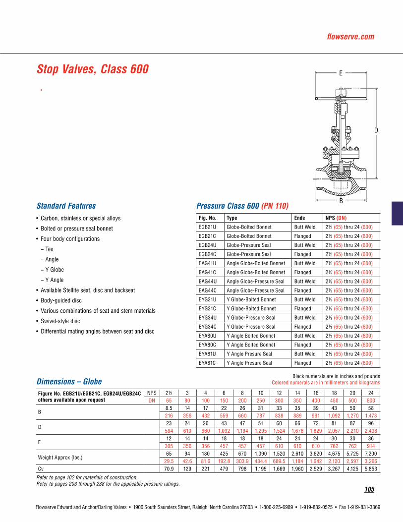
flowserve.com
105
Flowserve Edward and Anchor/Darling Valves • 1900 South Saunders Street, Raleigh, North Carolina 27603 • 1-800-225-6989 • 1-919-832-0525 • Fax 1-919-831-3369
Dimensions – GlobeBlack numerals are in inches and pounds
Colored numerals are in millimeters and kilograms
FigureNo.EGB21U/EGB21C,EGB24U/EGB24Cothersavailableuponrequest
NPS 21/2 3 4 6 8 10 12 14 16 18 20 24DN 65 80 100 150 200 250 300 350 400 450 500 600
B8.5 14 17 22 26 31 33 35 39 43 50 58216 356 432 559 660 787 838 889 991 1,092 1,270 1,473
D23 24 26 43 47 51 60 66 72 81 87 96
584 610 660 1,092 1,194 1,295 1,524 1,676 1,829 2,057 2,210 2,438
E12 14 14 18 18 18 24 24 24 30 30 36
305 356 356 457 457 457 610 610 610 762 762 914
Weight Approx (lbs.)65 94 180 425 670 1,090 1,520 2,610 3,620 4,675 5,725 7,200
29.5 42.6 81.6 192.8 303.9 434.4 689.5 1,184 1,642 2,120 2,597 3,266Cv 70.9 129 221 479 798 1,195 1,669 1,960 2,529 3,267 4,125 5,853
Refer to page 102 for materials of construction. Refer to pages 203 through 238 for the applicable pressure ratings.
Stop Valves, Class 600
Standard Features• Carbon, stainless or special alloys
• Bolted or pressure seal bonnet
• Four body configurations
− Tee
− Angle
− Y Globe
− Y Angle
• Available Stellite seat, disc and backseat
• Body-guided disc
• Various combinations of seat and stem materials
• Swivel-style disc
• Differential mating angles between seat and disc
Pressure Class 600 (PN 110)Fig. No. Type Ends NPS(DN)
EGB21U Globe-Bolted Bonnet Butt Weld 21/2 (65) thru 24 (600)
EGB21C Globe-Bolted Bonnet Flanged 21/2 (65) thru 24 (600)
EGB24U Globe-Pressure Seal Butt Weld 21/2 (65) thru 24 (600)
EGB24C Globe-Pressure Seal Flanged 21/2 (65) thru 24 (600)
EAG41U Angle Globe-Bolted Bonnet Butt Weld 21/2 (65) thru 24 (600)
EAG41C Angle Globe-Bolted Bonnet Flanged 21/2 (65) thru 24 (600)
EAG44U Angle Globe-Pressure Seal Butt Weld 21/2 (65) thru 24 (600)
EAG44C Angle Globe-Pressure Seal Flanged 21/2 (65) thru 24 (600)
EYG31U Y Globe-Bolted Bonnet Butt Weld 21/2 (65) thru 24 (600)
EYG31C Y Globe-Bolted Bonnet Flanged 21/2 (65) thru 24 (600)
EYG34U Y Globe-Pressure Seal Butt Weld 21/2 (65) thru 24 (600)
EYG34C Y Globe-Pressure Seal Flanged 21/2 (65) thru 24 (600)
EYA80U Y Angle Bolted Bonnet Butt Weld 21/2 (65) thru 24 (600)
EYA80C Y Angle Bolted Bonnet Flanged 21/2 (65) thru 24 (600)
EYA81U Y Angle Presure Seal Butt Weld 21/2 (65) thru 24 (600)
EYA81C Y Angle Presure Seal Flanged 21/2 (65) thru 24 (600)
D
B
E

106
Flowserve Edward and Anchor/Darling Valves • 1900 South Saunders Street, Raleigh, North Carolina 27603 • 1-800-225-6989 • 1-919-832-0525 • Fax 1-919-831-3369
Dimensions – GlobeBlack numerals are in inches and pounds
Colored numerals are in millimeters and kilograms
FigureNo.FGB24U Othersavailableuponrequest
NPS 21/2 3 4 6 8 10 12 14 16 18 20 24
DN 65 80 100 150 200 250 300 350 400 450 500 600
B13 12 18 20 26 31 36 40.5 43 48 52 58
330 305 457 508 660 787 914 1,029 1,092 1,219 1,321 1,473
D24 28 33 45 49 56 62 68 77 83 92 98610 711 838 1,143 1,245 1,422 1,575 1,727 1,957 2,108 2,337 2,489
E14 IMP 16 IMP 16 IMP 18 18 24 24 24 30 30 36 38
356 381 381 457 457 610 610 610 762 762 914 914
Weight Approx (lbs.)150 180 310 560 915 1,350 1,770 3,160 4,070 5,455 6,840 7,80068 81.6 140.6 254 415 612.4 802.9 1,433 1,846 2,474 3,102 3,538
Cv 83.3 107 217 421 745 1,133 1,644 2,021 2,515 3,298 4,002 5,492
Refer to page 102 for materials of construction. Refer to pages 203 through 238 for the applicable pressure ratings.
Stop Valves, Class 900
Standard Features• Carbon, stainless or special alloys
• Pressure seal bonnet
• Four body configurations
− Tee
− Angle
− Y Globe
− Y Angle
• Available Stellite seat, disc and backseat
• Body-guided disc
• Various combinations of seat and stem materials
• Swivel-style disc
• Differential mating angles between seat and disc
Pressure Class 600 (PN 150)Fig. No. Type Ends NPS(DN)
FGB24U Globe Butt Weld 21/2 (65) thru 24 (600)
FAG44U Angle Globe Butt Weld 21/2 (65) thru 24 (600)
FYG34U Y Globe Butt Weld 21/2 (65) thru 24 (600)
FYA81U Y Angle Butt Weld 21/2 (65) thru 24 (600)
D
E
B

flowserve.com
107
Flowserve Edward and Anchor/Darling Valves • 1900 South Saunders Street, Raleigh, North Carolina 27603 • 1-800-225-6989 • 1-919-832-0525 • Fax 1-919-831-3369
Standard Features• Carbon, stainless or special alloys
• Pressure seal bonnet
• Four body configurations
− Tee
− Angle
− Y Globe
− Y Angle
• Available Stellite seat, disc and backseat
• Body-guided disc
• Various combinations of seat and stem materials
• Swivel style disc
• Differential mating angles between seat and disc
Dimensions – GlobeBlack numerals are in inches and pounds
Colored numerals are in millimeters and kilograms
FigureNo.GGB24U,GAG44U,GYG34U,GYA81U Othersavailableuponrequest
NPS 21/2 3 4 6 8 10 12 14 16 18 20 24
DN 65 80 100 150 200 250 300 350 400 450 500 600
B13 15 18 24 29 34 38 40 45 51 58 68
330 381 457 610 737 864 965 1,016 1,143 1,295 1,473 1,727
D24 25 28 49 53 60 68 72 81 87 98 100610 635 711 1,245 1,346 1,524 1,651 1,829 2,057 2,210 2,438 2,540
E14 IMP 14 IMP 16 IMP 18 18 24 24 24 30 30 36 36
356 356 406 457 457 610 610 610 762 762 1,296 1,296
Weight Approx (lbs.)150 280 355 735 1,370 2,480 2,590 3,700 4,810 5,920 7,030 8,14068.0 127.0 161.0 333.4 621.4 1,125 1,175 1,678 2,182 2,685 3,189 3,692
Cv 83.3 119 201 435 733 1,102 1,552 1,813 2,345 3,097 3,929 5,567
Refer to page 102 for materials of construction. Refer to pages 203 through 238 for the applicable pressure ratings.
Pressure Class 1500 (PN 260)Fig. No. Type Ends NPS(DN)
GGB24U Globe Butt Weld 21/2 (65) thru 24 (600)
GAG44U Angle Globe Butt Weld 21/2 (65) thru 24 (600)
GYG34U Y Globe Butt Weld 21/2 (65) thru 24 (600)
GYA81U Y Angle Butt Weld 21/2 (65) thru 24 (600)
Stop Valves, Class 1500
D
E
B

108
Flowserve Edward and Anchor/Darling Valves • 1900 South Saunders Street, Raleigh, North Carolina 27603 • 1-800-225-6989 • 1-919-832-0525 • Fax 1-919-831-3369
Pageintentionallyleftblank

flowserve.com
109
Flowserve Edward and Anchor/Darling Valves • 1900 South Saunders Street, Raleigh, North Carolina 27603 • 1-800-225-6989 • 1-919-832-0525 • Fax 1-919-831-3369
EdwardCheckValves

110
Flowserve Edward and Anchor/Darling Valves • 1900 South Saunders Street, Raleigh, North Carolina 27603 • 1-800-225-6989 • 1-919-832-0525 • Fax 1-919-831-3369
Piston Check Valves, Class 600
Standard Features• Bodies and covers are of forged steel
(A105)
• Bolted cover
• Y Pattern
• Body-guided hardened stainless steel disc
• Integral Stellite seat
• Asbestos-free spiral-wound cover gasket
• Stainless steel spring (optional without springs)
Pressure Class 600 (PN 110)FIG.NO. TYPE ENDS NPS(DN)
838 Y Pattern Threaded 1/4 (8) thru 2 (50)
838Y Y Pattern Socket Weld 1/4 (8) thru 2 (50)
Dimensions – GlobeBlack numerals are in inches and pounds
Colored numerals are in millimeters and kilograms
FigureNo.838/838YNPS 1/4 3/8 1/2 3/4 1 11/4 11/2 2DN 8 10 15 20 25 32 40 50
A - End to End3 3 3 3.6 4.3 5.8 5.8 6.5
76 76 76 91 109 147 147 165
E - Center to Top2.8 2.8 2.8 3.3 3.8 4.6 4.6 5.171 71 71 84 97 117 117 130
Weight2 2 2 3.5 5 11 10 14
0.9 0.9 0.9 1.6 2.3 5 4.5 6.3
Refer to page 59 for materials of construction. Refer to pages 203 through 238 for the applicable pressure ratings.
838

flowserve.com
111
Flowserve Edward and Anchor/Darling Valves • 1900 South Saunders Street, Raleigh, North Carolina 27603 • 1-800-225-6989 • 1-919-832-0525 • Fax 1-919-831-3369
Univalve® Piston Check Valves, Class 1500
Standard Features• Available body materials
− SA105 carbon steel
− F22 alloy steel
− F316 stainless steel
− Other material on application
• Unwelded (graphitic seal) or welded cover
• Y Pattern
• Body-guided investment cast Stellite disc
• Integral Stellite seat
• Stainless steel spring (optional without springs)
Pressure Class 1500 (PN 260)Fig. No.
Type Ends NPS(DN)Welded Unweld.
36174 36274 Y Pattern Socket Weld 1/2 (15) thru 2-1/2 (65)
36178 36278 Y Pattern Butt Weld 1/2 (15) thru 4 (100)
DimensionsBlack numerals are in inches and pounds
Colored numerals are in millimeters and kilograms
Figure No. 36174, 36178, 36274, 36278NPS 1/2 3/4 1 1-1/4 1-1/2 2 2-1/2 3 4DN 15 20 25 32 40 50 65 80 100
A - End to End6.0 6.0 6.0 6.7 6.7 8.2 10.7 10.7 12.8152 152 152 170 170 208 272 272 325
AA - End Hub Diameter2.30 2.30 2.30 3.20 3.20 3.64 4.00 4.00 4.8058 58 58 81 81 92 102 102 122
B - Center to End4.0 4.0 4.0 4.8 4.8 6.1 7.1 7.1 8.8102 102 102 122 122 155 180 180 224
E - Center to Top3.9 3.9 3.9 5.0 5.0 5.8 7.2 7.2 7.899 99 99 127 127 147 183 183 198
Weight14 14 14 22 22 31 44 44 866 6 6 10 10 14 20 20 39
Refer to page 63 for materials of construction. Refer to pages 203 through 238 for the applicable pressure ratings.

112
Flowserve Edward and Anchor/Darling Valves • 1900 South Saunders Street, Raleigh, North Carolina 27603 • 1-800-225-6989 • 1-919-832-0525 • Fax 1-919-831-3369
Univalve® Piston Check Valves, Class 2500
Standard Features• Available body material
− SA105 carbon steel
− F22 alloy steel
− F316 stainless steel
− Other material on application
• Unwelded (graphitic seal) or welded cover
• Y Pattern
• Body-guided investment cast Stellite disc
• Integral Stellite seat
• Stainless steel spring (optional without springs)
Pressure Class 2500 (PN 420)Fig. No.
Type Ends NPS(DN)Welded Unweld.
66174 66274 Y Pattern Socket Weld 1/2 (15) thru 21/2 (65)
66178 66278 Y Pattern Butt Weld 1/2 (15) thru 4 (100)
Dimensions – GlobeBlack numerals are in inches and pounds
Colored numerals are in millimeters and kilograms
Figure No. 66174, 66178, 66274, 66278NPS 1/2 3/4 1 11/4 11/2 2 21/2 3 4DN 15 20 25 32 40 50 65 80 100
A - End to End6.0 6.0 6.0 6.7 6.7 10.7 12.8 12.8 12.8152 152 152 170 170 272 325 325 325
AA - End Hub Diameter2.30 2.30 2.30 3.20 3.20 4.00 4.80 4.80 4.8058 58 58 81 81 102 122 122 122
B - Center to End4.0 4.0 4.0 4.8 4.8 7.1 8.8 8.8 8.8102 102 102 122 122 180 224 224 224
E - Center to Top (Open)3.9 3.9 3.9 5.0 5.0 7.0 7.8 7.8 7.899 99 99 127 127 178 198 198 198
Weight14 14 14 22 22 52 86 86 866 6 6 10 10 24 39 39 39
Refer to page 63 for materials of construction. Refer to pages 203 through 238 for the applicable pressure ratings.

flowserve.com
113
Flowserve Edward and Anchor/Darling Valves • 1900 South Saunders Street, Raleigh, North Carolina 27603 • 1-800-225-6989 • 1-919-832-0525 • Fax 1-919-831-3369
Controlled Closure Check Valve
Standard Features• Minimizes waterhammer effects on
postulated feedwater line break
• Computerized modeling verified by dynamic testing
The Flowserve Edward Controlled Closure Check Valve was developed and qualified to serve a function that no other previous check valve could handle. If a feedwater line should rupture in a nuclear power plant, the reversed flow from the reactor or steam generator out of the containment boundary must be contained. Conventional check valves would close rapidly, but not fast enough to prevent high reverse flow velocity; closure of the conventional valve would produce severe pressure surges due to waterhammer—possibly severe enough to produce rupture of other piping or equipment.
The Controlled Closure Check Valve is much like a Flite-Flow piston lift check valve, but it has an integral “dashpot”—a plate with a close-clearance fit around the rod connecting the disc and piston. Flow paths sized for individual applications limit the flow out of the dashpot and consequently control the valve closing speed. See pg. 235-237 for a discussion of waterhammer and a comparison of the controlled closure check valve with other types.
As the final design section is very dependent on the specific application, consult with your Flowserve sales representative for more design details for this valve configuration.

114
Flowserve Edward and Anchor/Darling Valves • 1900 South Saunders Street, Raleigh, North Carolina 27603 • 1-800-225-6989 • 1-919-832-0525 • Fax 1-919-831-3369
Features and Description of Flowserve Edward Check ValvesOver 75 years of valve field experience, coupled with ongoing research and development programs, have led to Flowserve Edward valves’ reputation as a leader in supplying horizontal, angle, Flite-Flow and Elbow Down piston lift check valves.
These check valves incorporate time-proven design features such as equalizers for full lift at lower flows; body-guided disc-piston assemblies for seat alignment and stable operation; integral Stellite seating surfaces for long life and tight sealing; and streamlined flow shapes for low-pressure drop. Flowserve Edward valves maintain a reputation for the “Preferred” valve in critical high-pressure, high-temperature applications.
Flite-Flow®
Globe
Angle
For check or stop-check applications with a broad range of flow conditions, a “skirted” disc, identified by adding the suffix “K” to the valve figure number, may provide the required minimum lift at low flow while providing acceptable pressure drop at maximum flow. Specifically, the illustrated disc with a Mini-Skirt provides good low-flow performance while reducing CV by only 10%. See the Flowserve Edward Valves technical article EVAWP3019 for assistance on high-turndown applications.
Flowserve - Edward Skirted Check Valves

flowserve.com
115
Flowserve Edward and Anchor/Darling Valves • 1900 South Saunders Street, Raleigh, North Carolina 27603 • 1-800-225-6989 • 1-919-832-0525 • Fax 1-919-831-3369
Features and Description of Flowserve Edward One-Piece Tilting-Disc Check ValvesThe Edward tilting-disc check valve is designed to close as quickly as possible. It minimizes loud, damaging slamming and vibration noises caused when high-velocity reverse flow is allowed to build up before the completion of closing.
QuickClosing
Quick closing is achieved through a combination of several design construction features. The disc is dome-shaped to avoid hesitation of disc motion or closing, common to conventional flat discs. For minimum pendulum period—an important factor in assuring quick closing—the disc pivot is located close to the center of gravity of the disc.
All disc surfaces are open to line fluid so that no dashpot action can delay closing. The disc pivots on pin supports having chrome-plated bearings for minimum friction. Totally enclosed torsion springs in the pivot pins help speed the closing action, although the disc is counterweighted sufficiently to close automatically without aid from the springs whether the valve is in a vertical or horizontal position. Since the springs are fully enclosed in the pins, they are not subject to possible erosive effects of line fluids and foreign matter cannot get in. There is no bolting in the flow stream.
AdjustableHingePins
Available factory installed or as a conversion kit, Edward valves’ unique, adjustable hinge pin replaces the usual concentric hinge pins with double offset eccentric hinge pins, making core alignment a matter of simply dialing in the fit.
1. Cover retainer provides loading through the cover retainer and bolting to initiate a seal at the pressure seal gasket.
2. Cover is precision machined to retain pressure integrity and critical gasket seating surfaces.
3.Compositepressuresealgasket is a pre-loaded pressure energized flexible graphite composite for long, reliable service.
4. Integral hardsurfaced seats, both body and disc, provide positive shutoff and long seat life.
5.Springsensurequickclosing of the disc by providing a positive seating force to speed closing.
6.Hingepin provides a disc pivot point close to its center of gravity for fast response to flow reversals, which minimizes water-hammer effects.
7.Hingepin gasket is spiral wound, coated steel, or flexible graphite for long, reliable service.
8.Bodyfeatures a straight-thru compact design for low-pressure drop.
9.Discassembly is dome-shaped and counterweighted for fast response to flow reversals.
1.
2.
3.
4.
5.
6.
7.
8.
9.

116
Flowserve Edward and Anchor/Darling Valves • 1900 South Saunders Street, Raleigh, North Carolina 27603 • 1-800-225-6989 • 1-919-832-0525 • Fax 1-919-831-3369
Description(1) ASME/ASTMNo. ASME/ASTMNo. ASME/ASTMNo. ASME/ASTMNo.
Body/Cover* SA-216 Grade WCB
SA-216 Grade WCC
SA-217 Grade WC9
SA-351 Grade CF8M
Disc†† SA-105 —
SA-105 —
SA-182 Grade F22
SA-182 Grade F316
PressureSealGasket* Composite Pressure Seal Gasket
SpacerRing A-668 Grade 4140 MnPO4 Plated
A-668 Grade 4140 MnPO4 Plated
A-668 Grade 4140 MnPO4 Plated
Grade 182 Grade F6 CL4
GasketRetainer SA-182 Grade F6 CL4
A-182 Grade F6 CL4
A-565 Grade 616 HT
A-638 Grade 660 T2
CoverRetainer A-216 Grade WCB
A-216 Grade WCB
A-216 Grade WCB
A-216 Grade WCB
CoverRetainerCapscrewsorStuds
A-193 Grade B7
A-193 Grade B7
A-193 Grade B7
A-193 Grade B7
CoverRetainerNuts A-194 Grade 2H
A-194 Grade 2H
A-194 Grade 2H
A-194 Grade 2H
HingePinGasketSize21/2,3, 4
Spiral Wound Gasket (Asb. Free)
Spiral Wound Gasket (Asb. Free)
Spiral Wound Gasket (Asb. Free)
Spiral Wound Gasket (Asb. Free)
HingePinGasketSize6&Larger Graphite Gasket
HingePin A-182 Grade F6aCL4
A-182 Grade F6aCL4
A-565 Grade 616 HT
A-638 Grade 660 Type 2
HingePinBolts A-193 Grade B7
A-193 Grade B7
A-193 Grade B16
A-453 Grade 660B
HingePinRetainer A-105 —
A-105 —
A-182 Grade F22
A-182 Grade F316
HingePinSprings† A-313 A-313 A-313 A-313*Other material grades available on application. **All ANSI Class 600 valves utilize an asbestos-free spiral wound bonnet gasket. †Hinge Pin Torsion Springs required in size 6 and larger valves only. ††Sizes 21/2, 3 and 4, Pressure Classes 900, 1500 and 2500 – disc material is A732-GR21
This is not a complete list. Construction and materials will vary between sizes and pressure classes and may be changed without notice. For a complete, accurate and itemized description of a particular valve, contact your Flowserve Edward valves sales representative.
Parts Specification List for Flowserve Edward One-Piece Tilting-Disc Check Valve

flowserve.com
117
Flowserve Edward and Anchor/Darling Valves • 1900 South Saunders Street, Raleigh, North Carolina 27603 • 1-800-225-6989 • 1-919-832-0525 • Fax 1-919-831-3369
Check Valves, Class 600
Standard Features• Bodies and covers are cast steel
(WCB, WCC, WC9, CFBM)
• Bolted or pressure-seal cover
• Y Pattern, globe, angle, or tilting disc
• Integral Stellite seats
• Body-guided disc piston, globe, angle and Flite-Flow
• Long Terne# steel or pressure-seal gasket
• Equipped with equalizer, globe, angle and Flite-Flow
Pressure Class 600 (PN 110)*Fig. No.
Type Ends Bonnet NPS(DN)STDCL SPLCL
670Y 770Y Tilting Disc Butt Weld Bolted 6 (150) thru 20 (500)
690 — Globe Flanged Bolted
21/2 (65) thru 6 (150)690Y — Globe Butt Weld Bolted
691 — Angle Flanged Bolted
691Y — Angle Butt Weld Bolted
***692 — Flite-Flow Flanged *Pressure Seal3 (80) thru 32 (800)
692Y 792Y Flite-Flow Butt Weld *Pressure Seal
694 — Globe Flanged Pressure Seal
8 (200) thru 14 (350)694Y 794Y Globe Butt Weld Pressure Seal
695 — Angle Flanged Pressure Seal
695Y 795Y Angle Butt Weld Pressure Seal
* Size 3 and 4 - Bolted bonnet with asbestos-free spiral-wound gasket.
* Size 3 and 4 Butt weld Flite-Flow valves are Class 700.
Dimensions – Globe & AngleBlack numerals are in inches and pounds
Colored numerals are in millimeters and kilograms
FigureNo.690/690Y,691/691Y,694/694Y,695/695Y,794Y,795Y
NPS 21/2 3 4 5 6 8 10 12 14DN 65 80 100 125 150 200 250 300 350
C - Face to Face, Globe (Flanged)•13 14 17 20 22 26 31 33 35
330 356 432 508 559 660 787 838 889
D - Center to Face, Angle (Flanged)•6.5 7 8.5 10 11 13 15.5 16.5 17.5165 178 216 254 279 330 394 419 445
E - Center to Top, Globe6.6 7.1 8.9 11.4 13.1 17.3 20.2 23.2 25.1168 180 226 290 333 439 513 589 638
F - Center to Top, Angle4.8 5.0 6.4 8.0 8.9 11.9 13.4 15.5 16.6122 127 163 203 226 302 340 394 422
H - Clearance for Equalizer8.7 8.5 10 9.6 11 11.8 13 13.7 15.7221 216 254 244 279 300 330 348 399
Weight, Globe (Flanged)80 110 210 360 460 815 1290 1870 232036 50 95 163 209 370 585 848 1052
Weight, Globe (Welding)60 80 140 250 325 620 1040 1550 193027 36 64 113 147 281 472 703 875
Weight, Angle (Flanged)72 95 184 290 380 590 990 1490 183033 43 84 132 172 268 449 676 830
Weight, Angle (Welding)50 70 124 180 250 400 710 1170 144023 32 56 82 113 181 322 531 653
• Center-to-end or end-to-end dimensions for welding end valves same as center-to-contact-face or contact-face-to-contact-face dimensions for flanged end valves.
# Long Terne steel is a product coated by immersion in molten Terne metal. Terne metal is an alloy of lead and a small amount (about 3%) of tin.
*** Flanged valves available in sizes 3 through 16.
Refer to page 116 for materials of construction. Refer to pages 203 through 238 for the applicable pressure ratings.

118
Flowserve Edward and Anchor/Darling Valves • 1900 South Saunders Street, Raleigh, North Carolina 27603 • 1-800-225-6989 • 1-919-832-0525 • Fax 1-919-831-3369
Standard Features• Bodies and covers are cast steel
(WCB, WCC, WC9, CF8M)
• Bolted or pressure-seal cover
• Y Pattern, globe, angle or tilting disc
• Integral Stellite seats
• Body-guided disc piston, globe, angle and Flite-Flow
• Gasket: Sizes 3 and 4 asbestos-free, spiral wound; all others: composite pressure seal
• Equipped with equalizer, globe, angle and Flite-Flow
Dimensions – Flite-FlowBlack numerals are in inches and pounds
Colored numerals are in millimeters and kilograms
FigureNo.692Y/792Y***692NPS 3 4 6 8 10 12 14 16 20 24 26 28 32DN 80 100 150 200 250 300 250 400 500 600 650 700 800
A - End to End (Welding)13 15.5 20 26 31 38 38 41 60 66 70 81.5 90
330 394 508 660 787 965 965 1041 1524 1676 1778 2070 2286
A2 - Face to Face (Flanged) 16.75 21.5 29 33 39 45 45 52 * * * * *425 540 737 838 991 1143 1143 1321 * * * − −
E - Center to Top7 11 15.75 17.75 21.25 25.25 25.25 31.5 36.0 * * * *
178 279 400 451 540 641 641 800 914
H - Equalizer Clearance7 9 10 12 13 14 14 22 24 * * * *
178 229 254 305 330 356 356 559 610 * * * *
Weight (Welding)80 125 375 575 1000 1450 1450 3300 * * * * *35 55 170 261 454 658 658 1497
Weight (Flanged)120 200 520 750 1250 1900 2150 4300 * * − − −54 90 236 340 567 862 975 1950
Notes: Size 3 and 4 Buttweld Class 600 Flite-Flow valves are Class 700. * E, H and other dimensions and information supplied upon request. *** Flanged valves available in sizes 3 through 16.
Dimensions – Tilting Disc
FigureNo.670Y/770YNPS 6 8 10 12 14 16 18 20DN 150 200 250 300 350 400 450 500
A - End to End (Welding)19.5 22 28.5 34.5 34.5 43.25 48.25 53.5495 559 724 876 876 1099 1226 1359
E - Center to Top9.5 10.5 13.5 15.5 15.5 20.5 22.5 23.75241 267 343 394 394 521 572 603
W - Width15.25 17.5 21 25 25 32.25 34 38.5387 445 533 635 635 819 864 978
Weight (Welding)300 500 950 1450 1550 2550 3550 5650136 225 428 653 698 1148 1598 2543
Refer to page 116 for materials of construction. Refer to pages 203 through 238 for the applicable pressure ratings.
692Y
Check Valves, Class 600

flowserve.com
119
Flowserve Edward and Anchor/Darling Valves • 1900 South Saunders Street, Raleigh, North Carolina 27603 • 1-800-225-6989 • 1-919-832-0525 • Fax 1-919-831-3369
Check Valves, Class 900
Standard Features• Bodies and covers are cast steel
(WCB, WCC, WC9, CF8M)
• Pressure-seal cover
• Globe, angle and tilting-disc design
• Integral Stellite seats
• Body-guided disc piston (Globe and Angle)
• Equipped with equalizer (Globe and Angle)
Pressure Class 900 (PN 150)*Fig. No.
Type Ends NPS(DN)STDCL SPLCL
970Y 4370Y Tilting-Disc Butt Weld 21/2 (65) thru 24 (600)
4094 — Globe Flanged3 (80) thru 14 (350)
4094Y 4394Y Globe Butt Weld
4095 — Angle Flanged3 (80) thru 24 (600)
4095Y 4395Y Angle Butt Weld
4092 — Flite-Flow Flanged3 (80) thru 16 (400)
4092Y 4392Y Flite-Flow Butt Weld*
*Size 3 and 4 Buttweld Flite-Flow Valves are Class 1100
Dimensions – Globe & AngleBlack numerals are in inches and pounds
Colored numerals are in millimeters and kilograms
FigureNo.4094/4094Y,4095/4095Y,4394Y,4395Y
NPS 3 4 5 6 8 10 12 14DN 80 100 125 150 200 250 300 350
A - End to End (Welding)15 18 22 24 29 33 38 40.5
381 457 559 610 737 838 965 1029
B - Center to End (Welding)7.5 9 11 12 14.5 16.5 19 20.25190 229 279 305 368 419 483 514
C - Face to Face (Flanged)15 18 22 24 29 33 38 40.5
381 457 559 610 737 838 965 1029
D - Center to Face (Flanged)7.5 9 11 12 14.5 16.5 19 20.25190 229 279 305 368 419 483 514
E - Center to Top, Globe11 12 13.75 15.63 18.5 22.25 26.25 28.75
279 305 349 397 470 565 667 730
F - Center to Top, Angle9.25 10.25 11.25 12.5 16 16.75 21.5 21.5235 260 286 318 406 425 546 546
H - Clearance for Equalizer7.5 7.63 9.75 10.75 12.5 12.88 14.75 17.38190 194 248 273 318 327 275 441
Weight, Globe (Flanged)140 246 426 550 1188 1310 2710 382064 112 193 249 539 594 1229 1733
Weight, Globe (Welding)108 160 272 400 840 1090 2110 307049 73 123 181 381 494 957 1393
Weight, Angle (Flanged)134 217 356 485 898 1080 2165 234561 98 161 220 407 490 982 1064
Weight, Angle (Welding)115 131 202 290 510 860 1565 186052 59 92 132 231 390 710 844
Refer to page 116 for materials of construction. Refer to pages 203 through 238 for the applicable pressure ratings.

120
Flowserve Edward and Anchor/Darling Valves • 1900 South Saunders Street, Raleigh, North Carolina 27603 • 1-800-225-6989 • 1-919-832-0525 • Fax 1-919-831-3369
Check Valves, Class 900
Standard Features• Bodies and covers are cast steel
(WCB, WCC, WC9, CF8M)
• Pressure-seal cover
• Y Pattern
• Integral Stellite seats
• Body-guided disc piston
• Equipped with equalizer
Dimensions – Flite-FlowBlack numerals are in inches and pounds
Colored numerals are in millimeters and kilograms
FigureNo.4092/4092Y,4392YNPS 3 4 6 8 10 12 14 16DN 80 100 150 200 250 300 350 400
A1 - End to End (Welding)17 18.5 20 26 31 38 38 44.5
432 470 508 660 787 914 914 1092
A2 - Face to Face (Flanged)22.25 23.75 30 38 44 50 51 58565 603 762 965 1118 1270 1295 1473
E - Center to Top10 11 13.5 17.25 20.25 24 24 30
254 279 343 438 514 610 610 762
H - Equalizer Clearance9 9.3 10 12.5 16 15 15 25.75
229 236 254 318 406 381 381 654
Weight (Welding)130 175 300 710 1300 2050 2050 390059 79 136 322 590 930 930 1769
Weight (Flanged)190 250 520 1100 1850 2800 3200 530086 113 236 499 839 1270 1452 2404
Note: Size 3 and 4 Buttweld Class 900 Flite-Flow valves are Class 1100. * Impactor handwheel is standard on all valves. Refer to page 116 for materials of construction. Refer to pages 203 through 238 for the applicable pressure ratings.
H

flowserve.com
121
Flowserve Edward and Anchor/Darling Valves • 1900 South Saunders Street, Raleigh, North Carolina 27603 • 1-800-225-6989 • 1-919-832-0525 • Fax 1-919-831-3369
Check Valves Class 900
Dimensions – AngleBlack numerals are in inches and pounds
Colored numerals are in millimeters and kilograms
FigureNo.4095/4095Y,4395YNPS 16 18 20 24DN 400 450 500 600
B - Center to End, (Welding)26 29 32.5 39
660 737 825 991
F - Center to Top, Angle (Open)29 32 32 36
737 813 813 914
G - Handwheel Diameter20 21 21.5 30
508 533 546 762
Weight, Angle (Welding)2675 3710 4930 81901213 1682 2636 3714
Dimensions – Tilting-Disc
FigureNo.970Y,4370YNPS 21/2* 3* 4* 6 8 10DN 65 80 100 150 200 250
A - End to End (Welding)12 12 12 22 28 34
305 305 305 559 711 864
E - Center to Top7.25 7.25 7.25 9.25 11 13184 184 184 235 279 330
W - Width10.5 10.5 10.5 16.5 16 20.5267 267 267 419 406 521
Weight (Welding)95 95 120 535 600 101043 43 54 243 272 458
* Spiral-wound hinge pin gaskets; hinge pin torsion spring not required.
FigureNo.970Y,4370YNPS 12 14 16 18 20 24DN 300 350 400 450 500 600
A - End to End (Welding)42 40.5 47 53 51.5 78
1067 1029 1194 1346 1308 1981
E - Center to Top15.75 15.75 18.75 18.75 23 36400 400 476 476 584 914
W - Width26.5 26.5 29 29 37.5 55673 673 737 737 953 1397
Weight (Welding)2090 2090 3260 3300 4510 10,200948 948 1479 1497 2046 4627
Refer to page 116 for materials of construction. Refer to pages 203 through 238 for the applicable pressure ratings.

122
Flowserve Edward and Anchor/Darling Valves • 1900 South Saunders Street, Raleigh, North Carolina 27603 • 1-800-225-6989 • 1-919-832-0525 • Fax 1-919-831-3369
Check Valves, Class 1500
Standard Features• Bodies and covers are cast steel
(WCB, WCC, WC9, CF8M)
• Pressure-seal cover OS & Y
• Globe or angle design
• Integral Stellite seats
• Body-guided disc piston
• Equipped with equalizer
Pressure Class 1500 (PN 260)*Fig. No.
Type Ends NPS(DN)STDCL SPLCL
7594 — Globe Flanged21/2 (65) thru 14 (350)
7594Y 2094Y Globe Butt Weld
7595 — Angle Flanged21/2 (65) thru 24 (600)
7595Y 2095Y Angle Butt Weld
7592Y 2092Y Flite-Flow Butt Weld* 3 (80) thru 24 (600)
*Size 3 and 4 Buttweld Flite-Flow Valves are Class 1800.
Dimensions – Globe & AngleBlack numerals are in inches and pounds
Colored numerals are in millimeters and kilograms
FigureNo.2094Y,2095Y,7594/7594Y,7595/7595Y
NPS 21/2 3 4 5 6 8 10DN 65 80 100 125 150 200 250
A - End to End (Welding)13 15 18 22 24 29 33
330 381 457 559 610 737 838
B - Center to End (Welding)6.5 7.5 9 11 12 14.5 16.5165 190 229 279 305 368 419
C - Face to Face (Flanged)16.5 18.5 21.5 26.5 27.75 32.75 39419 470 546 673 705 832 991
D - Center to Face (Flanged)8.25 9.25 10.75 13.25 13.88 16.38 19.5210 235 273 337 353 416 495
E - Center to Top, Globe9.25 11 12 13.75 15 18.75 20.75235 279 305 349 381 476 527
F - Center to Top, Angle8.25 9.25 10.25 11.25 13 15.75 17.25210 235 260 286 330 400 438
H - Clearance for Equalizer6.75 7.75 7.75 10 10.75 12.75 14171 197 197 254 273 324 356
Weight, Globe (Flanged)125 195 320 534 684 1390 236057 88 145 242 310 631 1070
Weight, Globe (Welding)65 115 180 308 470 960 153029 52 82 140 213 435 694
Weight, Angle (Flanged)107 186 290 350 470 1070 106049 84 132 159 213 485 481
Weight, Angle (Welding)57 94 152 260 340 680 123026 43 69 118 154 308 558
Refer to page 116 for materials of construction. Refer to pages 203 through 238 for the applicable pressure ratings.

flowserve.com
123
Flowserve Edward and Anchor/Darling Valves • 1900 South Saunders Street, Raleigh, North Carolina 27603 • 1-800-225-6989 • 1-919-832-0525 • Fax 1-919-831-3369
Check Valves, Class 1500
Dimensions – Globe & AngleBlack numerals are in inches and pounds
Colored numerals are in millimeters and kilograms
FigureNo.2094Y,2095Y,7594/7594Y,7595/7595Y
NPS 12 14 16 18 20 24DN 300 350 400 450 500 600
A - End to End (Welding)38 40.5
Valve Not Available965 1029
B - Center to End (Welding)19 20.25 23.5 23.5 28.5 35.5
483 514 597 597 724 902
C - Face to Face (Flanged)44.5 49.5
Valve Not Available1130 1257
D - Center to Face (Flanged)22.25 24.75
Available Upon Request565 629
E - Center to Top, Globe24.25 30
Valve Not Available616 762
F - Center to Top, Angle20.5 25 24.5 24.5 42 51521 635 622 622 1067 1295
H - Clearance for Equalizer15 17.38 19.5 19.5 23 28.5
381 441 495 495 584 724
Weight, Globe (Flanged)3100 4400
Valve Not Available1406 1995
Weight, Globe (Welding)2310 3300
Available Upon Request1040 1497
Weight, Angle (Flanged)2320 3900
Valve Not Available1044 1769
Weight, Angle (Welding)1530 2060 4700 4880 6820 11,600686 927 2131 2213 3093 5261
Refer to page 116 for materials of construction. Refer to pages 203 through 238 for the applicable pressure ratings.
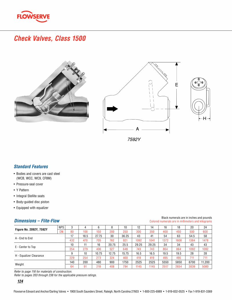
124
Flowserve Edward and Anchor/Darling Valves • 1900 South Saunders Street, Raleigh, North Carolina 27603 • 1-800-225-6989 • 1-919-832-0525 • Fax 1-919-831-3369
Check Valves, Class 1500
Standard Features• Bodies and covers are cast steel
(WCB, WCC, WC9, CF8M)
• Pressure-seal cover
• Y Pattern
• Integral Stellite seats
• Body-guided disc piston
• Equipped with equalizer
Dimensions – Flite-FlowBlack numerals are in inches and pounds
Colored numerals are in millimeters and kilograms
FigureNo.2092Y,7592YNPS 3 4 6 8 10 12 14 16 18 20 24DN 80 100 150 200 250 300 350 400 450 500 600
A - End to End17 18.5 27.75 30 36.25 43 41 54 63 54.5 58
432 470 705 762 921 1092 1041 1372 1600 1384 1478
E - Center to Top10 11 16 20.75 25.5 29.25 29.25 34 34 43 43
254 279 406 527 648 743 743 864 864 1092 1092
H - Equalizer Clearance9 10 10.75 12.75 15.75 16.5 16.5 19.5 19.5 28 28
229 254 273 324 400 419 419 495 495 711 711
Weight140 200 480 900 1750 2525 2525 5550 5850 6700 11,20064 91 218 408 794 1145 1145 2517 2654 3039 5080
Refer to page 116 for materials of construction. Refer to pages 203 through 238 for the applicable pressure ratings.

flowserve.com
125
Flowserve Edward and Anchor/Darling Valves • 1900 South Saunders Street, Raleigh, North Carolina 27603 • 1-800-225-6989 • 1-919-832-0525 • Fax 1-919-831-3369
Check Valves, Class 1500
Standard Features• Bodies and covers are cast steel
(WCB, WCC, WC9, CF8M)
• Pressure-seal cover
• Y Pattern
• Integral Stellite seats
• Body-guided disc piston
Pressure Class 1500 (PN 260)Fig. No.
Type Ends NPS(DN)STDCL SPLCL
1570Y 2070Y Tilting-Disc Butt Weld 21/2 (65) thru 24 (600)
Dimensions – Tilting-DiscBlack numerals are in inches and pounds
Colored numerals are in millimeters and kilograms
FigureNo.1570Y,2070YNPS 21/2* 3* 4* 6 8 10DN 65 80 100 150 200 250
A - End to End (Welding)12 12 12 22 28 34
305 305 305 559 711 864
E - Center to Top7.25 7.25 7.25 9.25 11 13184 184 184 235 279 330
W - Width10.5 10.5 10.5 16.5 16.75 20.5267 267 267 419 425 521
Weight (Welding)90 90 95 460 600 100541 41 43 209 272 456
* Spiral-wound hinge pin gaskets; hinge pin torsion spring not required.
FigureNo.1570YNPS 12 14 16 18 20 24DN 300 350 400 450 500 600
A - End to End (Welding)42 40.5 47 53 51.5 58
1067 1029 1194 1346 1308 1473
E - Center to Top15.75 15.75 18.75 18.75 23 36400 400 476 476 584 914
W - Width26.5 26.5 29 29 37.5 55673 673 737 737 953 1397
Weight (Welding) 1520 1550 3280 3590 4600 10,300689 703 1487 1628 2087 4672
Refer to page 116 for materials of construction. Refer to pages 203 through 238 for the applicable pressure ratings.

126
Flowserve Edward and Anchor/Darling Valves • 1900 South Saunders Street, Raleigh, North Carolina 27603 • 1-800-225-6989 • 1-919-832-0525 • Fax 1-919-831-3369
Pageintentionallyleftblank

flowserve.com
127
Flowserve Edward and Anchor/Darling Valves • 1900 South Saunders Street, Raleigh, North Carolina 27603 • 1-800-225-6989 • 1-919-832-0525 • Fax 1-919-831-3369
Anchor/DarlingCheckValves

128
Flowserve Edward and Anchor/Darling Valves • 1900 South Saunders Street, Raleigh, North Carolina 27603 • 1-800-225-6989 • 1-919-832-0525 • Fax 1-919-831-3369
Pageintentionallyleftblank

flowserve.com
129
Flowserve Edward and Anchor/Darling Valves • 1900 South Saunders Street, Raleigh, North Carolina 27603 • 1-800-225-6989 • 1-919-832-0525 • Fax 1-919-831-3369
Features and Description of 800 and 1878 Series Piston Check Valves
1. A compact, rugged, low-profile, precision cast body utilizes the latest investment casting technology. The valve offers smooth flow passages (not available in forged body designs).
2.Valvesarestocked with spring-loaded discs that provide a 5 psi cracking pressure.
3.DesignedforLowLeakageRateTesting (LLRT) and stocked with EPR/EPDM resilient seated discs. A hard-seated disc is available for high-temperature applications.
4. Thelightweightdisc minimizes pressure drop. Valves are stocked with disc and seat ring of solid non-Cobalt material. Solid Cobalt chrome discs and seats (AMS-5387) can also be provided on special order.
5.DesignedtomeetALARAprograms, the valve is made to greatly reduce worker exposure. The ADVanseal® design requires no grinding, cutting or welding.
5.
3.
4.
2.
1.
130
Flowserve Edward and Anchor/Darling Valves • 1900 South Saunders Street, Raleigh, North Carolina 27603 • 1-800-225-6989 • 1-919-832-0525 • Fax 1-919-831-3369
Parts Specification List for Anchor/Darling 800 and 1878 Piston Check ValvesStandard Features• Available body material
SA216-WCB SA351-CF8M
Anchor/Darling1878Seriespistoncheckvalvesfornuclearservicearenormallyfurnished in Class 1878. Other interpolated pressure classes are also available on application.
Parts shown are not applicable to all 1878 Series valves. Construction and materials for nuclear valves may vary depending upon customer design specifications. For a complete, accurate and itemized description of a particular valve, contact your local Flowserve valves sales representative.
Description ASME/ASTMNo. ASME/ASTMNo.Body SA216-WCB SA351-CF8MBonnet SA105 SA479-316Disc SA564-630-1075 SA564-630-1075Seat A276-S21800A A276-S21800ABonnetRetainer SA479-316 SA479-316Spring Inconel X Inconel X

flowserve.com
131
Flowserve Edward and Anchor/Darling Valves • 1900 South Saunders Street, Raleigh, North Carolina 27603 • 1-800-225-6989 • 1-919-832-0525 • Fax 1-919-831-3369
800 Series Piston Check Valves, Class 800
Standard Features• Pressure Class 800 (Intermediate)
(WCB, CF8M)
• Designed for long life
• Positive low pressure sealing
• Optional resilient seating for LLRT applications
• Contoured flow path provides maximum Cv
• ADVanseal® pressure sealing system
• Investment castings
• Quick disassembly/reassembly
Pressure Class 800 (PN 130)Fig. No. Type Ends NPS(DN)
UPC78S Piston Check Socket Weld 1/2 (15) thru 2 (50)
UPC78U Piston Check Butt Weld 1/2 (15) thru 2 (50)
Dimensions – T PatternBlack numerals are in inches and pounds
Colored numerals are in millimeters and kilograms
FigureNo.UPC78S,UPC78UNPS 1/2 3/4 1 2DN 15 20 25 50
A 3.6 3.7 4.4 7B 3.8 3.8 4.3 8.7Weight Approx. (lbs.) 4 4 6 15Cv 4.5 4.5 8 36
* Reduced ports Refer to page 130 for materials of construction. Refer to pages 203 through 238 for the applicable pressure ratings.

132
Flowserve Edward and Anchor/Darling Valves • 1900 South Saunders Street, Raleigh, North Carolina 27603 • 1-800-225-6989 • 1-919-832-0525 • Fax 1-919-831-3369
Features• Pressure Class 1878 (Intermediate)
(WCB, CF8M)
• Contoured flow path provides maximum Cv
• Quick disassembly
• Investment casting
• Non-cobalt hardfacing, standard
• Optional resilient seating for LLRT applications
• ADVanseal® pressure sealing system
• Positive low pressure sealing
• Designed for long wear
Series 1878 Piston Check Valves, Class 1878
Dimensions – Y PatternBlack numerals are in inches and pounds
Colored numerals are in millimeters and kilograms
FigureNo.NYP79S/NYP79UNPS 1/2 3/4 1 11/2 2* 2DN 15 20 25 40 50 50
A5.5 5.5 5.5 7.0 8.5 8.5140 140 140 178 216 216
B4.7 4.7 4.7 6.1 6.1 6.8119 119 119 155 155 173
Weight Approx (lbs.)13 13 13 26 26 305.9 5.9 5.9 11.8 11.8 13.6
Cv 14 16 16 48 48 76
* Reduced ports Refer to page 130 for materials of construction. Refer to pages 203 through 238 for the applicable pressure ratings.
Pressure Class 1878 (PN 325)Fig. No. Type Ends NPS(DN)
NYP79S Piston Check Socket Weld 1/2 (15) thru 2 (50)
NYP79U Piston Check Butt Weld 1/2 (15) thru 2 (50)
B
A
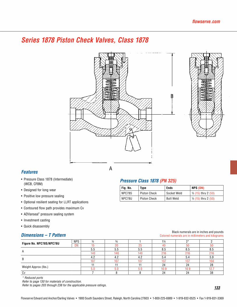
flowserve.com
133
Flowserve Edward and Anchor/Darling Valves • 1900 South Saunders Street, Raleigh, North Carolina 27603 • 1-800-225-6989 • 1-919-832-0525 • Fax 1-919-831-3369
Series 1878 Piston Check Valves, Class 1878
Features• Pressure Class 1878 (Intermediate)
(WCB, CF8M)
• Designed for long wear
• Positive low pressure sealing
• Optional resilient seating for LLRT applications
• Contoured flow path provides maximum Cv
• ADVanseal® pressure sealing system
• Investment casting
• Quick disassembly
Dimensions – T PatternBlack numerals are in inches and pounds
Colored numerals are in millimeters and kilograms
FigureNo.NPC78S/NPC78UNPS 1/2 3/4 1 11/2 2* 2DN 15 20 25 40 50 50
A5.5 5.5 5.5 8.5 8.5 8.5140 140 140 216 216 216
B4.2 4.2 4.2 5.4 5.4 5.9107 107 107 137 137 150
Weight Approx (lbs.)11 11 11 24 24 285.0 5.0 5.0 10.9 10.9 12.7
Cv 7 8 8 24 24 38
* Reduced ports Refer to page 130 for materials of construction. Refer to pages 203 through 238 for the applicable pressure ratings.
Pressure Class 1878 (PN 325)Fig. No. Type Ends NPS(DN)
NPC78S Piston Check Socket Weld 1/2 (15) thru 2 (50)
NPC78U Piston Check Butt Weld 1/2 (15) thru 2 (50)
B
A

134
Flowserve Edward and Anchor/Darling Valves • 1900 South Saunders Street, Raleigh, North Carolina 27603 • 1-800-225-6989 • 1-919-832-0525 • Fax 1-919-831-3369
NEED PDF: Anchor/Darling Double Disc Gate Valves.pdf
1.DesignedforLocalLeakageRateTesting (LLRT) and stocked with EPR resilient seated discs. A hard-seated disc is available for high-temperature applications.
• EPR resilient seating material qualified for radiation environments: 2.2X10⁷ RADS (integrated dosage) 420˚F for 6 years in steam or water 450˚F short-term service 5-year shelf life
• Disc SA564-630 heat treated at 1075˚F for -high hardness to resist abrasion - available with metal seat or dual seat
as shown
2. Disc nut fastener is locked in position to prevent loosening during operation.
3. Disc arms is hinge mounted on pads, readily accessible for adjustment and replacement.
4.Studsthreadedinbody to simplify and reduce time for disassembly. The (8) studs for 11/2" and 2" valves and (6) studs for 1/2" through 1" valves provide uniform compression of the spiral-wound gasket, to ensure positive joint sealing.
5. Clear flow path design minimizes pressure drop.
6.Built-incompressionstop ensures proper gasket compression.
7.Valvesarestocked with disc and seat ring of solid non-Cobalt material. Solid Cobalt chrome seat (AMS-5387) can also be provided on special order.
Features and Description of 1878 Series Swing-Check Valves
EnlargedDetailAResilientSeatedDisc
EnlargedDetailAHardSeatedDisc
6.
5.
7.
4.
2.
1.
3.

flowserve.com
135
Flowserve Edward and Anchor/Darling Valves • 1900 South Saunders Street, Raleigh, North Carolina 27603 • 1-800-225-6989 • 1-919-832-0525 • Fax 1-919-831-3369
Parts Specification List for Anchor/Darling 1878 Swing-Check Valves
Standard Features• Available body material
SA216-WCB SA351-CF8M
Anchor/Darling1878Seriesswing-checkvalvesfornuclearservicearenormallyfurnished in Class 1878. Other interpolated pressure classes are also available on application.
Parts shown are not applicable to all 1878 valves. Construction and materials for nuclear valves may vary depending upon customer design specifications. For a complete, accurate and itemized description of a particular valve, contact your local Flowserve valves sales representative.
Description ASME/ASTMNo. ASME/ASTMNo.Body SA216-WCB SA351-CF8MBonnet SA216-WCB SA351-CF8MHinge A351-CF8M A351-CF8MDisc SA564-630-1075 SA564-630-1075Seat A276-S21800A A276-S21800AStuds SA193-B7 SA193-B7

136
Flowserve Edward and Anchor/Darling Valves • 1900 South Saunders Street, Raleigh, North Carolina 27603 • 1-800-225-6989 • 1-919-832-0525 • Fax 1-919-831-3369
Series 1878 Swing-Check Valves – Bolted Bonnet, Class 1878
Features• Pressure Class 1878 (Intermediate)
(WCB, CF8M)
• Tight sealing
• Optional resilient seating for LLRT applications
• Minimum pressure drop
• Installation in vertical lines (with flow upward) or horizontal lines
• Ease of maintenance
• Internal disc assembly readily removed
• Low Delta P to open
• Disc arm tail stop
DimensionsBlack numerals are in inches and pounds
Colored numerals are in millimeters and kilograms
FigureNo.NPC51S/NPC51UNPS 1/2 3/4 1 11/2 2DN 15 20 25 40 50
A5.5 5.5 5.5 8.5 8.5140 140 140 216 216
L5.8 5.8 5.8 8 8147 147 147 203 203
AA5.0 5.0 5.0 7.0 7.0127 127 127 178 178
Weight Approx (lbs.)25 25 25 70 70
11.3 11.3 11.3 31.8 31.8Cv 3 8 14 55 85
Cv is based on sufficient flow to maintain disc in full open position. Refer to page 135 for materials of construction. Refer to pages 203 through 238 for the applicable pressure ratings.
Pressure Class 1878 (PN 325)Fig. No. Type Ends NPS(DN)
NSC51S Swing Check Socket Weld 1/2 (15) thru 2 (50)
NSC51U Swing Check Butt Weld 1/2 (15) thru 2 (50)
L
A
AA

flowserve.com
137
Flowserve Edward and Anchor/Darling Valves • 1900 South Saunders Street, Raleigh, North Carolina 27603 • 1-800-225-6989 • 1-919-832-0525 • Fax 1-919-831-3369
Series 1878 Swing-Check Valves – Pressure Seal Bonnet, Class 1878
Features• Pressure Class 1878 (Intermediate)
(WCB, CF8M)
• Tight sealing
• Minimum pressure drop
• One-piece investment cast body
• Low Delta P to open
• Solid, non-cobalt seat and disc
• Disc arm tail stop
• Optional resilient seating for LLRT applications
• ADVanseal® pressure sealing system
DimensionsBlack numerals are in inches and pounds
Colored numerals are in millimeters and kilograms
FigureNo.NSC58S/NSC58UNPS 1/2 3/4 1 11/2 2DN 15 20 25 40 50
A5.5 5.5 5.5 8.5 8.5140 140 140 216 216
B4.8 4.8 4.8 6.3 6.3122 122 122 160 160
Weight Approx (lbs.)20 20 20 45 459.1 9.1 9.1 20.4 20.4
Cv 3 8 14 85 85
Other sizes available upon request. Refer to page 135 for materials of construction. Refer to pages 203 through 238 for the applicable pressure ratings.
Pressure Class 1878 (PN 325)Fig. No. Type Ends NPS(DN)
NSC58S Swing Check Socket Weld 1/2 (15) thru 2 (50)
NSC58U Swing Check Butt Weld 1/2 (15) thru 2 (50)
B
A
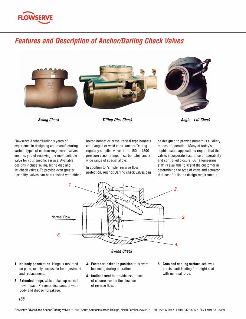
138
Flowserve Edward and Anchor/Darling Valves • 1900 South Saunders Street, Raleigh, North Carolina 27603 • 1-800-225-6989 • 1-919-832-0525 • Fax 1-919-831-3369
Features and Description of Anchor/Darling Check Valves
Flowserve Anchor/Darling’s years of experience in designing and manufacturing various types of custom-engineered valves ensures you of receiving the most suitable valve for your specific service. Available designs include swing, tilting disc and lift check valves. To provide even greater flexibility, valves can be furnished with either
bolted bonnet or pressure seal type bonnets and flanged or weld ends. Anchor/Darling regularly supplies valves from 150 to 4500 pressure class ratings in carbon steel and a wide range of special alloys.
In addition to “simple” reverse flow protection, Anchor/Darling check valves can
be designed to provide numerous auxiliary modes of operation. Many of today’s sophisticated applications require that the valves incorporate assurance of operability and controlled closure. Our engineering staff is available to assist the customer in determining the type of valve and actuator that best fulfills the design requirements.
1.Nobodypenetration. Hinge is mounted on pads, readily accessible for adjustment and replacement.
2.Extendedhinge, which takes up normal flow impact. Prevents disc contact with body and disc pin breakage.
3.Fastenerlockedinposition to prevent loosening during operation.
4. Inclined seat to provide assurance of closure even in the absence of reverse flow.
5. Crowned sealing surface achieves precise unit loading for a tight seal with minimal force.
Swing Check Tilting-Disc Check Angle - Lift Check
Swing Check
Normal Flow

flowserve.com
139
Flowserve Edward and Anchor/Darling Valves • 1900 South Saunders Street, Raleigh, North Carolina 27603 • 1-800-225-6989 • 1-919-832-0525 • Fax 1-919-831-3369
Features and Description of Flowserve – Anchor/Darling Check Valves
1.Discstopimpactsbody away from sealing surfaces; it also maintains disc open in the best position to minimize pressure drop.
2.Hydrofoilprofile maintains disc stability while being lifted by hydrodynamic forces at any flow, including pulsating.
3. Cast bodies and disc permit the internal flow passages to be designed with smooth, large radius curves.
4. Differential seat angles between disc and seat ring ensures better seal with low seating force.
5.Seatringsaresealweldedto minimize distortion from body stress while retaining ease of replacement.
1.Fullbodyguides ensure correct seat alignment.
2.Plugskirtprevents plug from cocking even under turbulent flow conditions.
3. Differential mating angles between plug and seat ring ensure tight seal with low seating force.
4. Cast bodies permit the internal flow passage to be designed with large radius curves.
5.Swivelplug ensures proper seat alignment and tight seal.
Tilting-Disc Check
Lift Check
Normal Flow
Normal Flow

140
Flowserve Edward and Anchor/Darling Valves • 1900 South Saunders Street, Raleigh, North Carolina 27603 • 1-800-225-6989 • 1-919-832-0525 • Fax 1-919-831-3369
Description(1) ASME/ASTMNo. ASME/ASTMNo. ASME/ASTMNo. ASME/ASTMNo. ASME/ASTMNo.
Body SA-216 Grade WCB
SA-216 Grade WCC
SA-217 Grade WC9
SA-351 Grade CF8
SA-351 Grade CF8M
Bonnet Cap SA-515 Grade 70 A-105 A-182
Grade F22SA-240
Grade 304SA-240
Grade 316
Disc SA-216 Grade WCB
SA-105 —
SA-182 Grade F22
SA-351 Grade CFB
SA-351 Grade CF8M
PressureSealGasket* Composite Pressure Seal Gasket
BonnetCapscrewsorStuds SA-193 Grade B7
A-193 Grade B7
A-193 Grade B7
SA-193 Grade B7
SA-193 Grade B7
Bonnet Nuts A-194 Grade 2H
A-194 Grade 2H
A-194 Grade 2H
A-194 Grade 2H
A-194 Grade 2H
HingePin A-582 Grade 416T
A-182 Grade F6aCL4
A-565 Grade 616 HT
A-582 Grade 416T
A-582 Grade 416T
HingePinBolts A-193 Grade B7
A-193 Grade B7
A-193 Grade B16
A-453 Grade 660B
A-453 Grade 660B
HingePinRetainer SA-515 Grade 70
A-105 —
A-182 Grade F22
SA-240 Grade 304
SA-240 Grade 316
*Other material grades available on application.
This is not a complete list. Construction and materials will vary between sizes and pressure classes and may be changed without notice. For a complete, accurate and itemized description of a particular valve, contact your Flowserve valves sales representative.
Parts Specification List for Flowserve Anchor/Darling Tilting-Disc Check Valves

flowserve.com
141
Flowserve Edward and Anchor/Darling Valves • 1900 South Saunders Street, Raleigh, North Carolina 27603 • 1-800-225-6989 • 1-919-832-0525 • Fax 1-919-831-3369
Description(1) ASME/ASTMNo. ASME/ASTMNo. ASME/ASTMNo.
Body SA-216 Grade WCB
SA-351 Grade CF8
SA-351 Grade CF8M
Bonnet Cap SA-515 Grade 70
SA-240 Grade F304
SA-240 Grade 316
Hinge A-216 Grade WCB
A-351 Grade CF8
A-351 Grade CF8M
Disc SA-105 —
SA-182 Grade F304
SA-182 Grade F316
PressureSealGasket* Composite Pressure Seal Gasket
BonnetCapscrewsorStuds A-193 Grade B7
A-193 Grade B7
A-193 Grade B7
Bonnet Cover Nuts A-194 Grade 2H
A-194 Grade 2H
A-194 Grade 2H
HingePin A-479 Grade 316
A-479 Grade 316
A-564 Grade 630-1075
HingePinRetainer SA-216 Grade WCB
SA-182 Grade F316
SA-240 Grade 316
*Other material grades available on application.
This is not a complete list. Construction and materials will vary between sizes and pressure classes and may be changed without notice. For a complete, accurate and itemized description of a particular valve, contact your Flowserve valves sales representative.
Parts Specification List for Flowserve Anchor/Darling Swing-Check Valves
142
Flowserve Edward and Anchor/Darling Valves • 1900 South Saunders Street, Raleigh, North Carolina 27603 • 1-800-225-6989 • 1-919-832-0525 • Fax 1-919-831-3369
Description(1) ASME/ASTMNo. ASME/ASTMNo. ASME/ASTMNo.
Body/Cover SA-216 Grade WCB
SA-351 Grade CF8
SA-351 Grade CF8M
Disc SA-105 —
SA-182 Grade F304
SA-182 Grade F316
PressureSealGasket* Composite Pressure Seal Gasket
CoverCapscrewsorStuds A-193 Grade B7
A-193 Grade B7
A-193 Grade B7
Cover Nuts A-194 Grade 2H
A-194 Grade 2H
A-194 Grade 2H
*Other material grades available on application.
This is not a complete list. Construction and materials will vary between sizes and pressure classes and may be changed without notice. For a complete, accurate and itemized description of a particular valve, contact your Flowserve valves sales representative.
Parts Specification List for Flowserve Anchor/Darling Lift-Check Valves

flowserve.com
143
Flowserve Edward and Anchor/Darling Valves • 1900 South Saunders Street, Raleigh, North Carolina 27603 • 1-800-225-6989 • 1-919-832-0525 • Fax 1-919-831-3369
DimensionsBlack numerals are in inches and pounds
Colored numerals are in millimeters and kilograms
FigureNo.BTD63U/BTD63CNPS 21/2 3 4 6 8 10 12 14 16 18 20 24DN 65 80 100 150 200 250 300 350 400 450 500 600
A2.5 3 4 6 8 10 12 13.3 16.3 17.3 19.3 23.364 76 102 152 203 254 305 338 414 439 490 592
B8.5 9.5 11.5 14 19.5 12.5 27.5 31 34 38.5 38.5 44216 241 292 356 495 622 699 787 864 978 978 1,118
C6.5 7 7.5 9 10 12.5 13.5 15 17.5 18 21 23165 178 191 229 254 318 343 381 445 457 533 584
Weight Approx (lbs.)55 75 110 200 305 480 625 945 1,210 1,675 2,440 2,920
25.9 34.0 49.9 90.7 138.3 217.7 283.5 428.7 548.9 759.8 1,106.8 1,324.5Cv 175 275 500 1,175 2,200 3,525 5,175 6,400 8,625 11,200 14,075 20,850
Refer to page 140 for materials of construction. Refer to pages 203 through 238 for the applicable pressure ratings.
Tilting-Disc Check Valves, Class 150
Standard Features• Carbon, stainless or special alloys
• Bolted bonnet
• Available Stellite seat and disc
• Easily accessible hinge
• Hydrofoil-style disc maintains stability
• Heavy counterweight ensures fast reaction
• Waterhammer is minimized
Pressure Class 150 (PN 25)Fig. No. Type Ends NPS(DN)
BTD63U Tilting-Disc Check Butt Weld 21/2 (65) thru 24 (600)
BTD63C Tilting-Disc Check Flanged 21/2 (65) thru 24 (600)
C
A
B

144
Flowserve Edward and Anchor/Darling Valves • 1900 South Saunders Street, Raleigh, North Carolina 27603 • 1-800-225-6989 • 1-919-832-0525 • Fax 1-919-831-3369
DimensionsBlack numerals are in inches and pounds
Colored numerals are in millimeters and kilograms
FigureNo.CTD63U/CTD63CNPS 21/2 3 4 6 8 10 12 14 16 18 20 24DN 65 80 100 150 200 250 300 350 400 450 500 600
A2.5 3 4 6 8 10 12 13.3 15.3 17 19 2364 76 102 152 203 254 305 338 389 432 483 584
B11.5 12.5 14 17.5 21 24.5 28 33 34 38.5 40 44292 318 356 445 533 600 711 838 864 978 1,016 1,118
C6.5 7 7.5 10 11.5 13.5 17.5 18 19 20 21.5 23165 178 191 254 292 343 445 457 483 508 546 584
Weight Approx (lbs.)70 90 190 375 440 690 905 1,135 1,315 1,930 2,635 3,730
31.8 40.8 86.2 170.1 199.6 313.0 410.5 514.8 596.5 875.4 1,195.2 1,691.9Cv 175 275 500 1,175 2,200 3,525 5,175 6,400 8,625 10,875 13,700 20,425
Refer to page 140 for materials of construction. Refer to pages 203 through 238 for the applicable pressure ratings.
Tilting-Disc Check Valves, Class 300
Standard Features• Carbon, stainless or special alloys
• Bolted bonnet
• Available Stellite seat and disc
• Easily accessible hinge
• Hydrofoil-style disc maintains stability
• Heavy counterweight ensures fast reaction
• Waterhammer is minimized
Pressure Class 300 (PN 50)Fig. No. Type Ends NPS(DN)
CTD63U Tilting-Disc Check Butt Weld 21/2 (65) thru 24 (600)
CTD63C Tilting-Disc Check Flanged 21/2 (65) thru 24 (600)
A
C
B

flowserve.com
145
Flowserve Edward and Anchor/Darling Valves • 1900 South Saunders Street, Raleigh, North Carolina 27603 • 1-800-225-6989 • 1-919-832-0525 • Fax 1-919-831-3369
Dimensions – Tilting-DiscBlack numerals are in inches and pounds
Colored numerals are in millimeters and kilograms
FigureNo.ETD63U/ETD63C, ETD67U/ETD67C
NPS 21/2 3 4 6 8 10 12 14 16 18 20 24DN 65 80 100 150 200 250 300 350 400 450 500 600
A2.5 3 4 6 7.9 9.8 11.8 12.9 14.8 16.5 18.3 2264 76 102 127 200 248 298 327 375 470 464 559
B8.5 10 12 18 23 28 32 35 39 43 47 55216 254 305 457 584 711 813 889 991 1,092 1,194 1,397
C5 6 7 9 11 12 13.5 15 17 21 25 27.5
152 152 178 229 279 305 343 381 432 533 660 699
Weight Approx (lbs.)55 65 85 125 295 475 820 1,615 2,000 2,700 2,900 3,10025 29.5 38.6 56.7 133.8 215.5 372.0 823.3 907.2 1,225 1,315 1,406
Cv 175 275 500 1,275 2,100 3,300 4,900 5,950 7,950 10,100 12,450 18,375
Refer to page 140 for materials of construction. Refer to pages 203 through 238 for the applicable pressure ratings.
Tilting-Disc Check Valves, Class 600
Standard Features• Carbon, stainless or special alloys
• Bolted bonnet or pressure seal
• Available Stellite seat and disc
• Easily accessible hinge
• Hydrofoil-style disc maintains stability
• Heavy counterweight ensures fast reaction
• Waterhammer is minimized
Pressure Class 600 (PN 110)Fig. No. BonnetType Type Ends NPS(DN)
ETD63U Bolted Bonnet Tilting-Disc Check Butt Weld 21/2 (65) thru 24 (600)
ETD63C Bolted Bonnet Tilting-Disc Check Flanged 21/2 (65) thru 24 (600)
ETD67U Pressure Seal Tilting-Disc Check Butt Weld 21/2 (65) thru 24 (600)
ETD67C Pressure Seal Tilting-Disc Check Flanged 21/2 (65) thru 24 (600)
A
C
B

146
Flowserve Edward and Anchor/Darling Valves • 1900 South Saunders Street, Raleigh, North Carolina 27603 • 1-800-225-6989 • 1-919-832-0525 • Fax 1-919-831-3369
Dimensions – Tilting-DiscBlack numerals are in inches and pounds
Colored numerals are in millimeters and kilograms
FigureNo.FTD67U/FTD67CNPS 21/2 3 4 6 8 10 12 14 16 18 20 24DN 65 80 100 150 200 250 300 350 400 450 500 600
A2.3 2.9 3.9 5.8 7.5 9.4 11.1 12.3 14 15.8 17.5 2157 73 99 146 191 238 282 311 356 400 445 533
B10 12 14 20 26 31 38 39 43 46 50 59
254 305 356 508 660 787 914 991 1,092 1,219 1,270 1,499
C6 7 7 12 12 13 15 16 21 22.5 25 28
152 178 178 305 305 330 381 406 533 572 635 711
Weight Approx (lbs.)75 100 225 350 675 990 1,875 2,315 2,775 3,845 5,250 9,600
34.0 45.4 102.0 158.8 305.2 449.1 759.8 1,050 1,259 1,744 2,381 4,309Cv 150 250 450 1,075 1,900 3,050 4,375 5,400 7,150 9,200 11,450 16,750
Refer to page 140 for materials of construction. Refer to pages 203 through 238 for the applicable pressure ratings.
Tilting-Disc Check Valves, Class 900
Standard Features• Carbon, stainless or special alloys
• Pressure seal
• Available Stellite seat and disc
• Easily accessible hinge
• Hydrofoil-style disc maintains stability
• Heavy counterweight ensures fast reaction
• Waterhammer is minimized
Pressure Class 900 (PN 150)Fig. No. Type Ends NPS(DN)
FTD67U Tilting-Disc Check Butt Weld 21/2 (65) thru 24 (600)
FTD67C Tilting-Disc Check Flanged 21/2 (65) thru 24 (600)
A
C
B
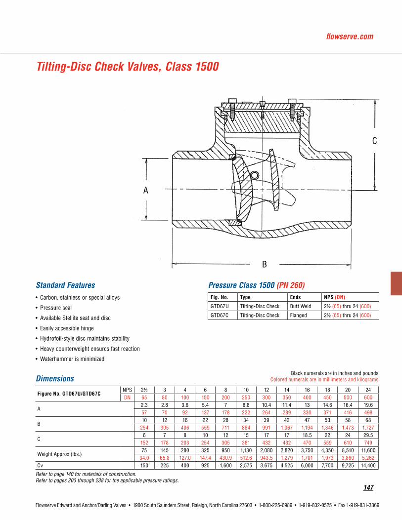
flowserve.com
147
Flowserve Edward and Anchor/Darling Valves • 1900 South Saunders Street, Raleigh, North Carolina 27603 • 1-800-225-6989 • 1-919-832-0525 • Fax 1-919-831-3369
A
C
B
Tilting-Disc Check Valves, Class 1500
Standard Features• Carbon, stainless or special alloys
• Pressure seal
• Available Stellite seat and disc
• Easily accessible hinge
• Hydrofoil-style disc maintains stability
• Heavy counterweight ensures fast reaction
• Waterhammer is minimized
Pressure Class 1500 (PN 260)Fig. No. Type Ends NPS(DN)
GTD67U Tilting-Disc Check Butt Weld 21/2 (65) thru 24 (600)
GTD67C Tilting-Disc Check Flanged 21/2 (65) thru 24 (600)
DimensionsBlack numerals are in inches and pounds
Colored numerals are in millimeters and kilograms
FigureNo.GTD67U/GTD67CNPS 21/2 3 4 6 8 10 12 14 16 18 20 24DN 65 80 100 150 200 250 300 350 400 450 500 600
A2.3 2.8 3.6 5.4 7 8.8 10.4 11.4 13 14.6 16.4 19.657 70 92 137 178 222 264 289 330 371 416 498
B10 12 16 22 28 34 39 42 47 53 58 68
254 305 406 559 711 864 991 1,067 1,194 1,346 1,473 1,727
C6 7 8 10 12 15 17 17 18.5 22 24 29.5
152 178 203 254 305 381 432 432 470 559 610 749
Weight Approx (lbs.)75 145 280 325 950 1,130 2,080 2,820 3,750 4,350 8,510 11,600
34.0 65.8 127.0 147.4 430.9 512.6 943.5 1,279 1,701 1,973 3,860 5,262Cv 150 225 400 925 1,600 2,575 3,675 4,525 6,000 7,700 9,725 14,400
Refer to page 140 for materials of construction. Refer to pages 203 through 238 for the applicable pressure ratings.

148
Flowserve Edward and Anchor/Darling Valves • 1900 South Saunders Street, Raleigh, North Carolina 27603 • 1-800-225-6989 • 1-919-832-0525 • Fax 1-919-831-3369
DimensionsBlack numerals are in inches and pounds
Colored numerals are in millimeters and kilograms
FigureNo.BSC52U/BSC52CNPS 21/2 3 4 6 8 10 12 14 16 18 20 24DN 65 80 100 150 200 250 300 350 400 450 500 600
A2.5 3 4 6 8 10 12 13.3 16.3 17.3 19.3 23.364 76 102 152 203 254 305 338 389 439 490 592
B8.5 9.5 11.5 14 19.5 12.5 27.5 31 34 38.5 38.5 44216 241 292 356 495 622 699 787 864 978 978 1,118
C6 6 6.5 8.5 11 12.5 13.5 15 16 18 21.5 25
152 152 165 216 279 318 343 381 406 457 546 635
Weight Approx (lbs.)35 75 90 190 240 430 625 720 975 1,260 1,635 2,475
15.8 34.0 40.8 86.2 108.9 195.0 283.5 326.6 442.3 571.5 741.6 1,122.7Cv 175 275 525 1,225 2,225 3,600 5,250 6,500 8,750 11,375 14,425 21,400
Refer to page 141 for materials of construction. Refer to pages 203 through 238 for the applicable pressure ratings.
Standard Features• Carbon, stainless or special alloys
• Bolted bonnet
• Available Stellite seat and disc
• No body penetration
• Easily accessible hinge
• Extended hinge, preventing disc contact with body
• Inclined seat to ensure closure even in no-flow condition
Swing-Check Valves, Class 150
Pressure Class 150 (PN 25)Fig. No. Type Ends NPS(DN)
BSC52U Swing Check Butt Weld 21/2 (65) thru 24 (600)
BSC52C Swing Check Flanged 21/2 (65) thru 24 (600)
B
A
C

flowserve.com
149
Flowserve Edward and Anchor/Darling Valves • 1900 South Saunders Street, Raleigh, North Carolina 27603 • 1-800-225-6989 • 1-919-832-0525 • Fax 1-919-831-3369
DimensionsBlack numerals are in inches and pounds
Colored numerals are in millimeters and kilograms
FigureNo.CSC51U/CSC51CNPS 21/2 3 4 6 8 10 12 14 16 18 20 24DN 65 80 100 150 200 250 300 350 400 450 500 600
A2.5 3 4 6 8 10 12 13.3 15.3 17 19 2364 76 102 152 203 254 305 338 389 439 490 584
B11.5 12.5 14 17.5 21 24.5 28 33 34 38.5 40 44292 318 356 445 533 600 711 838 864 978 1,016 1,118
C6 6.5 7.5 9.5 12 14.5 15.5 16.5 18 20 23.5 28
152 168 191 241 305 368 394 419 457 508 597 711
Weight Approx (lbs.)75 100 120 280 400 650 780 990 1,245 1,645 2,325 3,290
34.0 45.4 54.4 127.0 181.4 294.8 353.8 449.1 564.7 746.2 1,054.6 1,492.3Cv 175 275 525 1,225 2,225 3,600 5,250 6,500 8,750 11,050 14,050 20,950
Refer to page 141 for materials of construction. Refer to pages 203 through 238 for the applicable pressure ratings.
Swing-Check Valves, Class 300
Standard Features• Carbon, stainless or special alloys
• Bolted bonnet
• Available Stellite seat and disc
• No body penetration
• Easily accessible hinge
• Extended hinge, preventing disc contact with body
• Inclined seat to ensure closure even in no-flow condition
Pressure Class 300 (PN 50)Fig. No. Type Ends NPS(DN)
CSC51U Swing Check Butt Weld 21/2 (65) thru 24 (600)
CSC51C Swing Check Flanged 21/2 (65) thru 24 (600)
A
C
B

150
Flowserve Edward and Anchor/Darling Valves • 1900 South Saunders Street, Raleigh, North Carolina 27603 • 1-800-225-6989 • 1-919-832-0525 • Fax 1-919-831-3369
Dimensions – SwingBlack numerals are in inches and pounds
Colored numerals are in millimeters and kilograms
FigureNo.ESC51U/ESC51C, ESC58U/ESC58C
NPS 21/2 3 4 6 8 10 12 14 16 18 20 24DN 65 80 100 150 200 250 300 350 400 450 500 600
A2.5 3 4 6 7.9 9.8 11.8 12.9 14.8 16.5 18.3 2264 76 102 127 200 248 298 327 375 470 464 559
B8.5 10 12 18 23 28 32 35 39 43 47 55216 254 305 457 584 711 813 889 991 1,092 1,194 1,397
C5 7 9 13 14 18 20 23 24 25 31 36
127 178 229 330 356 457 508 584 610 635 787 914
Weight Approx (lbs.)35 45 155 295 575 705 1,145 1,630 2,255 2,875 3,495 3,915
15.9 20.4 70.3 133.8 260.8 319.8 519.4 739.4 1,023 1,304 1,585 1,776Cv 175 275 500 1,200 2,125 3,375 5,000 6,100 8,125 10,325 12,850 19,000
Refer to page 141 for materials of construction. Refer to pages 203 through 238 for the applicable pressure ratings.
Swing-Check Valves, Class 600
Standard Features• Carbon, stainless or special alloys
• Bolted bonnet or pressure seal
• Available Stellite seat and disc
• No body penetration
• Easily accessible hinge
• Extended hinge, preventing disc contact with body
• Inclined seat to ensure closure even in no-flow condition
Pressure Class 600 (PN 110)Fig. No. BonnetType Type Ends NPS(DN)
ESC51U Bolted Bonnet Swing Check Butt Weld 21/2 (65) thru 24 (600)
ESC51C Bolted Bonnet Swing Check Flanged 21/2 (65) thru 24 (600)
ESC58U Pressure Seal Swing Check Butt Weld 21/2 (65) thru 24 (600)
ESC58C Pressure Seal Swing Check Flanged 21/2 (65) thru 24 (600)
A
C
B

flowserve.com
151
Flowserve Edward and Anchor/Darling Valves • 1900 South Saunders Street, Raleigh, North Carolina 27603 • 1-800-225-6989 • 1-919-832-0525 • Fax 1-919-831-3369
Dimensions – SwingBlack numerals are in inches and pounds
Colored numerals are in millimeters and kilograms
FigureNo.FSC58U/FSC58CNPS 21/2 3 4 6 8 10 12 14 16 18 20 24DN 65 80 100 150 200 250 300 350 400 450 500 600
A2.3 2.9 3.9 5.8 7.5 9.4 11.1 12.3 14 15.8 17.5 2157 73 99 146 191 238 282 311 356 400 445 533
B10 12 14 20 26 31 36 39 43 46 50 59
254 305 356 508 660 787 914 991 1,092 1,168 1,270 1,499
C6.5 6.5 9.5 12 13.5 15 18 20 22 24 25 29165 165 241 305 343 381 457 508 559 610 635 737
Weight Approx (lbs.)50 65 145 375 600 860 1,670 1,985 2,415 3,145 4,105 6,380
22.7 29.5 65.8 170.1 272.1 385.6 757.5 900.4 1,095 1,427 1,862 2,894Cv 150 250 475 1,100 1,925 3,100 4,475 5,525 7,325 9,425 11,825 17,300
Refer to page 141 for materials of construction. Refer to pages 203 through 238 for the applicable pressure ratings.
Swing-Check Valves, Class 900
Standard Features• Carbon, stainless or special alloys
• Pressure seal
• Available Stellite seat and disc
• No body penetration
• Easily accessible hinge
• Extended hinge, preventing disc contact with body
• Inclined seat to ensure closure even in no-flow condition
Pressure Class 900 (PN 150)Fig. No. Type Ends NPS(DN)
FSC58U Swing Check Butt Weld 21/2 (65) thru 24 (600)
FSC58C Swing Check Flanged 21/2 (65) thru 24 (600)
A
C
B

152
Flowserve Edward and Anchor/Darling Valves • 1900 South Saunders Street, Raleigh, North Carolina 27603 • 1-800-225-6989 • 1-919-832-0525 • Fax 1-919-831-3369
Pressure Class 1500 (PN 260)Fig. No. Type Ends NPS(DN)
GSC58U Swing Check Butt Weld 21/2 (65) thru 24 (600)
GSC58C Swing Check Flanged 21/2 (65) thru 24 (600)
Dimensions – SwingBlack numerals are in inches and pounds
Colored numerals are in millimeters and kilograms
FigureNo.GSC58U/GSC58CNPS 21/2 3 4 6 8 10 12 14 16 18 20 24DN 65 80 100 150 200 250 300 350 400 450 500 600
A2.3 2.8 3.6 5.4 7 8.8 10.4 11.4 13 14.6 16.4 19.657 70 92 137 178 222 264 289 330 371 416 498
B10 12 16 22 28 34 39 42 47 53 58 68
254 305 406 559 711 864 991 1,067 1,194 1,346 1,473 1,727
C8.5 9 10 12 18 22 26 30 36 42 47 57165 229 254 305 457 559 711 762 914 1,067 1,194 1,448
Weight Approx (lbs.)50 75 160 570 1,085 1,415 2,175 2,960 3,985 4,715 7,665 8,380
22.7 34.0 68.0 258.6 492.2 641.8 986.6 1,343 1,808 2,139 3,431 3,801Cv 150 225 400 950 1,675 2,675 3,825 4,650 6,175 7,925 10,025 14,725
Refer to page 141 for materials of construction. Refer to pages 203 through 238 for the applicable pressure ratings.
Swing-Check Valves, Class 1500
Standard Features• Carbon, stainless or special alloys
• Bolted bonnet or pressure seal
• Available Stellite seat and disc
• No body penetration
• Easily accessible hinge
• Extended hinge, preventing disc contact with body
• Inclined seat to ensure closure even in no-flow condition
A
C
B

flowserve.com
153
Flowserve Edward and Anchor/Darling Valves • 1900 South Saunders Street, Raleigh, North Carolina 27603 • 1-800-225-6989 • 1-919-832-0525 • Fax 1-919-831-3369
Anchor/DarlingBallValves

154
Flowserve Edward and Anchor/Darling Valves • 1900 South Saunders Street, Raleigh, North Carolina 27603 • 1-800-225-6989 • 1-919-832-0525 • Fax 1-919-831-3369
Features and Description of Flowserve Anchor/Darling Ball ValvesApplicationsAnchor/Darling ball valves are designed and engineered to provide dependable service in demanding nuclear applications, where high performance and low maintenance costs are a necessity. Typical applications include:
• Sampling Systems (gaseous & liquid)
• Rad-Waste Cleanup Systems
• Component Cooling Systems
• Chemical Make-up Systems
• Service Water Systems
• Instrument Air Service
• Containment Sump
• Vents & Drains
• Air Lock Systems
Valve OptionsUnmatched flexibility and cost efficiency are derived from the wide selection of three-piece and top-entry valves and the variety of selectable options. These options encompass:
• Valve Types & Sizes
• Port Configurations
• Seating Materials
• Valve Body Materials
• Ball Materials
• Pressure Classes
• Valve Operators
• Accessories
FeaturesAnchor/Darling ball valves offer several inherent features in their design that are unmatched by conventional gate and globe valves. These ball valves provide:
• Lower pressure drop due to straight-through flow paths
• Fewer internal crevices reducing the potential for “crud” traps
• Easier and “less costly” repairs—no required cutting or disrupting of pipes is required
• Lower radiation exposure to personnel due to quick removal of all valve internals
• Lower center of gravity minimizing seismic loads
Flowserve Anchor/Darling ball valves also feature pressure-seated, blow-out-proof stems, which utilize line pressure to ensure maximum sealing action.
Flowservecansupplycustom-engineeredsafety-relatedandnon-safety-relatedballvalvestomeetyourspecifica-tionsandrequirements.

flowserve.com
155
Flowserve Edward and Anchor/Darling Valves • 1900 South Saunders Street, Raleigh, North Carolina 27603 • 1-800-225-6989 • 1-919-832-0525 • Fax 1-919-831-3369
Materials
DescriptionTypicalCarbonSteel TypicalStainlessSteel
Material MaterialSpec.ASME-SAASTM-A Material MaterialSpec.ASME-SAASTM-A
Body Carbon Steel SA 696-C with Phosphate Stainless Steel SA479-316
Ball Stainless Steel SA479-316 Stainless Steel SA479-316
Seats See Chart See Chart
Stem Stainless Steel A564-630-1075 Stainless Steel A564-630-1075
End Pieces Carbon Steel SA696-C with Phosphate Stainless Steel SA479-316
Gland Ring Stainless Steel AISI 300 Stainless Steel AISI 300
Handle Carbon Steel AISI 1010* Carbon Steel AISI 1010*
Hex Nuts Carbon Steel SA194-2H with Phosphate Carbon Steel SA194-2H with Phosphate
Lockwashers Stainless Steel AISI 300 Stainless Steel AISI 300
Hex Capscrews Alloy Steel SA193-87 with Phosphate Alloy Steel SA193-87 with Phosphate
O-Rings (Body) See Chart See Chart
O-Rings (Stem) See Chart See Chart
Stem Seals See Chart See Chart
Locknut (Stem) Stainless Steel AISI 300 Stainless Steel AISI 300
*Denotes with zinc and plastisol coatings
Seat & Seal Material Selection Chart
Set Seats StemO-Ring BodyO-Rings StemSeals
A UHMWPE EPR EPR UHMWPE
B EPDM EPR EPR UHMWPE
C Teflon EPR EPR RPTFE
D Viton Viton Viton UHMWPE
Standard Features• Available body material
SA696-C SA479-316
• Full or standard port
• Bi-directional sealing
Parts Specification List for Anchor/Darling Ball Valves
Parts shown are not applicable to all Ball Valves. Construction and materials for nuclear valves vary depending on customer design specifica-tions. For a complete, accurate and itemized description of a particular valve, contact your local Flowserve valves sales representative.

156
Flowserve Edward and Anchor/Darling Valves • 1900 South Saunders Street, Raleigh, North Carolina 27603 • 1-800-225-6989 • 1-919-832-0525 • Fax 1-919-831-3369
Standard Seating MaterialsTemperature/radiation limits are based upon actual seating material qualification testing and/or manufacturer’s recommendations:
E-Series/C-Series/Top-Entry Ball Valve Data
SeatMaterial Max.Temperature(continuous) RadiationLimit(5-yearexposure)
Teflon 300°F 2 x 10⁴ Rads
Reinforced Teflon 350°F 5 x 10⁵ Rads
UHMWPE 200°F 8 x 10⁷ Rads
Tefzel 300°F 9 x 10⁷ Rads
Viton 400°F 5 x 10⁷ Rads
EPDM 400°F 5 x 10⁷ Rads
Flow Coefficients (CV )
ValveSize StandardPort FullPort
1/2" N/A 16.5
3/4" 16.5 27
1" 27 50
11/4" 50 78
11/2" 78 120
2" 120 195
21/2" 195 240
3" 240 700
4" 700 1400
6" 1400 N/A
Optional seating materials are available for severe service applications; contact Flowserve for application assistance. Higher temperature excursions are permissible; consult factory for limitations.
Valve OperatorsFlowserve has a complete line of valve operators available for use with Anchor/Darling ball valves.
Other valve operators can be specified and supplied to suit customer requirements. Additionally, valves can be configured to mate with many existing valve operators (if appropriately sized) and accessory items (i.e., position indicating and limit switches).
Note: Values based on flow of water in gallons per minute (GPM) at standard conditions to achieve a one (1) PSI pressure drop.

flowserve.com
157
Flowserve Edward and Anchor/Darling Valves • 1900 South Saunders Street, Raleigh, North Carolina 27603 • 1-800-225-6989 • 1-919-832-0525 • Fax 1-919-831-3369
Top-Entry Ball Valves, Class 150
DimensionsBlack numerals are in inches and pounds
Colored numerals are in millimeters and kilograms
FigureNo.BBV96U,StandardPortNPS 1 11/4 11/2 2 21/2 3 4 6DN 25 32 40 50 65 80 100 150
A5.3 8.5 7.5 9.5 11.5 11.1 14 22135 216 191 241 292 282 356 559
C4.8 5.2 5.9 6.1 7.8 8 10.1 11.9122 132 150 155 198 203 257 302
G5.9 6.3 7.4 7.6 9.1 9.4 11.4127 160 188 193 231 239 290
DimensionsBlack numerals are in inches and pounds
Colored numerals are in millimeters and kilograms
FigureNo.BBV93U,FullPortNPS 1 11/4 11/2 2 21/2 3 4DN 25 32 40 50 65 80 100
A8.5 7.5 9.5 11.5 11.1 14 22216 191 241 292 282 356 559
C5.2 5.9 6.1 7.8 8 10.1 11.9132 150 155 198 203 257 302
G6.3 7.4 7.6 9.1 9.4 11.4160 188 193 231 239 290
Valve weights for top-entry valves are not published due to the customized nature of this product and the associated variables, which can affect total weight. After receiving customer’s requirements for valve size, materials, valve operator requirements, etc., Anchor/Darling can furnish assembly weights. Consult factory for certified weights.Refer to page 155 for materials of construction. Refer to pages 203 through 238 for the applicable pressure ratings.
Pressure Class 150 (PN 25)Fig. No. Type Ends NPS(DN)
BBV96U Ball Butt Weld 1 (25) thru 6 (150)
Pressure Class 150 (PN 25)Fig. No. Type Ends NPS(DN)
BBV93U Ball Butt Weld 1 (25) thru 4 (100)
A
C G

158
Flowserve Edward and Anchor/Darling Valves • 1900 South Saunders Street, Raleigh, North Carolina 27603 • 1-800-225-6989 • 1-919-832-0525 • Fax 1-919-831-3369
Top-Entry Ball Valves, Class 300
DimensionsBlack numerals are in inches and pounds
Colored numerals are in millimeters and kilograms
FigureNo.CBV96U,StandardPortNPS 1 11/4 11/2 2 21/2 3 4 6DN 25 32 40 50 65 80 100 150
A5.3 8.5 7.5 9.5 11.5 11.1 14 22135 216 191 241 292 282 356 559
C4.8 5.2 5.9 6.1 7.8 8 10.1 11.9122 132 150 155 198 203 257 302
G5.9 6.3 7.4 7.6 9.1 9.4 11.4127 160 188 193 231 239 290
DimensionsBlack numerals are in inches and pounds
Colored numerals are in millimeters and kilograms
FigureNo.CBV93U,FullPortNPS 1 11/4 11/2 2 21/2 3 4DN 25 32 40 50 65 80 100
A8.5 7.5 9.5 11.5 11.1 14 22216 191 241 292 282 356 559
C5.2 5.9 6.1 7.8 8 10.1 11.9132 150 155 198 203 257 302
G6.3 7.4 7.6 9.1 9.4 11.4160 188 193 231 239 290
Valve weights for top-entry valves are not published due to the customized nature of this product and the associated variables, which can affect total weight. After receiving customer’s requirements for valve size, materials, valve operator requirements, etc., Anchor/Darling can furnish assembly weights. Consult factory for certified weights.
Refer to page 155 for materials of construction. Refer to pages 203 through 238 for the applicable pressure ratings.
Pressure Class 300 (PN 50)Fig. No. Type Ends NPS(DN)
CBV96U Ball Butt Weld 1 (25) thru 6 (150)
Pressure Class 300 (PN 50)Fig. No. Type Ends NPS(DN)
CBV93U Ball Butt Weld 1 (25) thru 4 (100)
A
C G

flowserve.com
159
Flowserve Edward and Anchor/Darling Valves • 1900 South Saunders Street, Raleigh, North Carolina 27603 • 1-800-225-6989 • 1-919-832-0525 • Fax 1-919-831-3369
Top-Entry Ball Valves, Class 300
DimensionsBlack numerals are in inches and pounds
Colored numerals are in millimeters and kilograms
FigureNo.BBV94SNPS 3/4 1 11/4 11/2 2DN 20 25 32 40 50
A 2.8 3.3 3.8 4.3 571 84 95 108 127
C 1.6 2.1 2.4 2.6 2.941 53 61 66 74
D 2.5 3.3 4 4.3 4.664 84 102 109 117
F 2.6 3.1 3.6 4 4.666 79 91 102 117
G 6 6 7 7 9
152 152 178 178 229
Weight Approx (lbs.)2.9 4.7 7.3 10.4 15.81.3 2.1 3.3 4.7 7.2
Cv 16.5 27 50 78 120
Refer to page 155 for materials of construction. Refer to pages 203 through 238 for the applicable pressure ratings.
Pressure Class 150 (PN 25)Fig. No. Type Ends NPS(DN)
BBV94S Ball Socket Weld 3/4 (20) thru 2 (50)
NotesDrawing has typical information only.
For installation purposes, use certified drawing.
E-Series Ball Valves Standard Port, Class 150 Carbon or stainless steel ball valve with lever actuator
A
C D
F
G

160
Flowserve Edward and Anchor/Darling Valves • 1900 South Saunders Street, Raleigh, North Carolina 27603 • 1-800-225-6989 • 1-919-832-0525 • Fax 1-919-831-3369
DimensionsBlack numerals are in inches and pounds
Colored numerals are in millimeters and kilograms
FigureNo.BBV94UNPS 21/2 3 4 6DN 65 80 100 150
A5.5 6.8 8.3 10.5140 173 211 267
C3.3 3.6 5.3 7.384 91 135 185
D4.9 5.8 7.1 9.1124 147 180 231
F6.0 6.8 8.1 10.1152 173 206 257
G9.0 12.0 16.0 28.0229 305 406 711
Weight Approx (lbs.)18 30 56 1208.2 13.6 25.4 54.4
Cv 195 240 700 1400
Refer to page 155 for materials of construction. Refer to pages 203 through 238 for the applicable pressure ratings.
Pressure Class 150 (PN 25)Fig. No. Type Ends NPS(DN)
BBV94U Ball Butt Weld 21/2 (20) thru 6 (50)
NotesDrawing has typical information only.
For installation purposes, use certified drawing.
E-Series Ball Valves, Standard Port, Class 150Carbon or stainless steel ball valve with lever actuator
A F
D
G
C

flowserve.com
161
Flowserve Edward and Anchor/Darling Valves • 1900 South Saunders Street, Raleigh, North Carolina 27603 • 1-800-225-6989 • 1-919-832-0525 • Fax 1-919-831-3369
NotesDrawing has typical information only.
For installation purposes, use certified drawing.
DimensionsBlack numerals are in inches and pounds
Colored numerals are in millimeters and kilograms
FigureNo.BBV94CNPS 21/2 3 4 6DN 65 80 100 150
A5.5 6.8 8.3 10.5140 173 211 267
C3.3 3.6 5.3 7.384 91 135 185
D4.9 5.8 7.1 9.1124 147 180 231
F10.3 10.3 12 14.3262 262 305 363
G9.0 12.0 16.0 28229 305 406 711
Weight Approx (lbs.)38 54 92 181
17.2 24.5 41.7 82.1Cv 195 240 700 1400
Refer to page 155 for materials of construction. Refer to pages 203 through 238 for the applicable pressure ratings.
Pressure Class 150 (PN 25)Fig. No. Type Ends NPS(DN)
BBV94C Ball Flanged 21/2 (65) thru 6 (150)
E-Series Ball Valves, Standard Port, Class 150Carbon or stainless steel ball valve with lever actuator
A F
C
G
D

162
Flowserve Edward and Anchor/Darling Valves • 1900 South Saunders Street, Raleigh, North Carolina 27603 • 1-800-225-6989 • 1-919-832-0525 • Fax 1-919-831-3369
DimensionsBlack numerals are in inches and pounds
Colored numerals are in millimeters and kilograms
FigureNo.BBV95SNPS 1/2 3/4 1 11/4 11/2 2DN 15 20 25 32 40 50
A2.8 3.3 3.8 4.3 5.0 6.371 84 97 109 127 160
C1.6 2.1 2.4 2.6 2.9 3.341 53 61 66 74 84
D2.5 3.3 4 4.3 4.6 564 84 102 109 117 127
F2.6 3.1 3.6 4 4.6 666 79 91 102 117 152
G6 6 7 7 9 9
152 152 178 178 229 229
Weight Approx2.9 4.7 7.3 10.4 15.8 23.81.3 2.1 3.3 4.7 7.2 10.8
Cv 16.5 27 50 78 120 195
Refer to page 155 for materials of construction. Refer to pages 203 through 238 for the applicable pressure ratings.
E-Series Ball Valves Full Port, Class 150Carbon or stainless steel ball valve with lever actuator
Pressure Class 150 (PN 25)Fig. No. Type Ends NPS(DN)
BBV95S Ball Socket Weld 1/2 (15) thru 2 (50)
NotesDrawing has typical information only.
For installation purposes, use certified drawing.
A
C D
F
G

flowserve.com
163
Flowserve Edward and Anchor/Darling Valves • 1900 South Saunders Street, Raleigh, North Carolina 27603 • 1-800-225-6989 • 1-919-832-0525 • Fax 1-919-831-3369
Dimensions
Black numerals are in inches and poundsColored numerals are in millimeters
and kilograms
FigureNo.BBV95UNPS 3 4DN 80 100
A8.3 10.5211 267
B3.589
C5.3 7.3135 185
D7.1 9.3180 236
F8.1 10.1206 257
G16.0 28.0406 711
Weight Approx (lbs.)57 120
25.9 54.4Cv 700 1400
Refer to page 155 for materials of construction. Refer to pages 203 through 238 for the applicable pressure ratings.
Pressure Class 150 (PN 25)Fig. No. Type Ends NPS(DN)
BBV95U Ball Butt Weld 3 (80) and 4 (100)
NotesDrawing has typical information only.
For installation purposes, use certified drawing.
E-Series Ball Valves, Full Port, Class 150Carbon or stainless steel ball valve with lever actuator
AF
BD
G
C
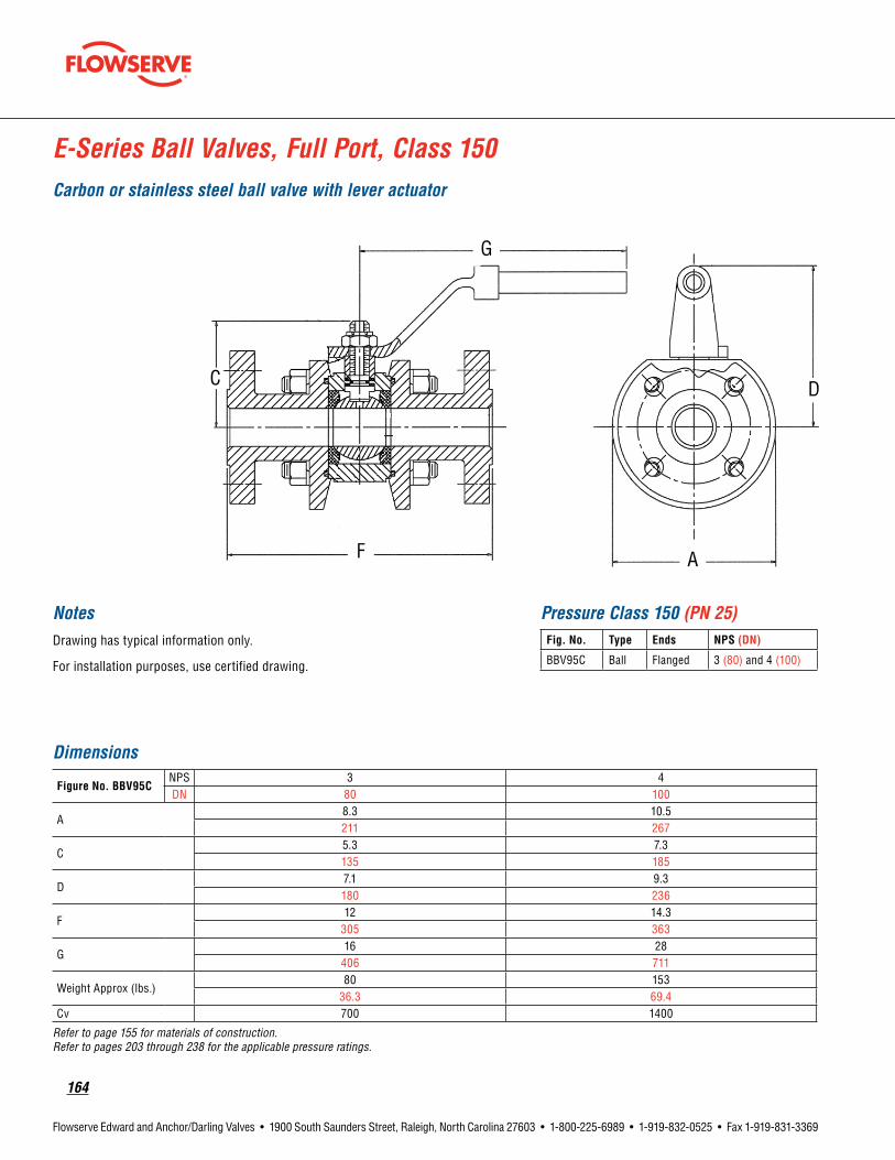
164
Flowserve Edward and Anchor/Darling Valves • 1900 South Saunders Street, Raleigh, North Carolina 27603 • 1-800-225-6989 • 1-919-832-0525 • Fax 1-919-831-3369
Dimensions
FigureNo.BBV95CNPS 3 4DN 80 100
A8.3 10.5211 267
C5.3 7.3135 185
D7.1 9.3180 236
F12 14.3
305 363
G16 28
406 711
Weight Approx (lbs.)80 153
36.3 69.4Cv 700 1400
Refer to page 155 for materials of construction. Refer to pages 203 through 238 for the applicable pressure ratings.
E-Series Ball Valves, Full Port, Class 150Carbon or stainless steel ball valve with lever actuator
NotesDrawing has typical information only.
For installation purposes, use certified drawing.
Pressure Class 150 (PN 25)Fig. No. Type Ends NPS(DN)
BBV95C Ball Flanged 3 (80) and 4 (100)
C
F A
G
D

flowserve.com
165
Flowserve Edward and Anchor/Darling Valves • 1900 South Saunders Street, Raleigh, North Carolina 27603 • 1-800-225-6989 • 1-919-832-0525 • Fax 1-919-831-3369
A
C D
F
G
NotesDrawing has typical information only.
For installation purposes, use certified drawing.
Pressure Class 300 (PN 50)Fig. No. Type Ends NPS(DN)
CBV94S Ball Socket Weld 3/4 (20) thru 2 (50)
DimensionsBlack numerals are in inches and pounds
Colored numerals are in millimeters and kilograms
FigureNo.CBV94SNPS 3/4 1 11/4 11/2 2DN 20 25 32 40 50
A2.8 3.3 3.8 4.3 571 84 95 108 127
C1.6 2.1 2.4 2.6 2.941 53 61 66 74
D2.5 3.3 4 4.3 4.664 84 102 109 117
F2.6 3.1 3.6 4 4.666 79 91 102 117
G6 6 7 7 9
152 152 178 178 229
Weight Approx (lbs.)2.9 4.7 7.3 10.4 15.81.3 2.1 3.3 4.7 7.2
Cv 16.5 27 50 78 120
Refer to page 155 for materials of construction. Refer to pages 203 through 238 for the applicable pressure ratings.
E-Series Ball Valves Standard Port, Class 300Carbon or stainless steel ball valve with lever actuator
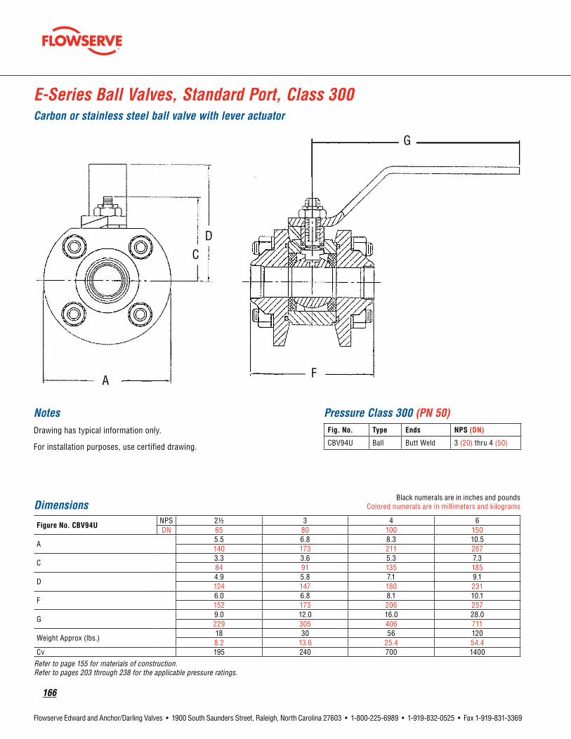
166
Flowserve Edward and Anchor/Darling Valves • 1900 South Saunders Street, Raleigh, North Carolina 27603 • 1-800-225-6989 • 1-919-832-0525 • Fax 1-919-831-3369
NotesDrawing has typical information only.
For installation purposes, use certified drawing.
Pressure Class 300 (PN 50)Fig. No. Type Ends NPS(DN)
CBV94U Ball Butt Weld 3 (20) thru 4 (50)
E-Series Ball Valves, Standard Port, Class 300Carbon or stainless steel ball valve with lever actuator
DimensionsBlack numerals are in inches and pounds
Colored numerals are in millimeters and kilograms
FigureNo.CBV94UNPS 21/2 3 4 6DN 65 80 100 150
A5.5 6.8 8.3 10.5140 173 211 267
C3.3 3.6 5.3 7.384 91 135 185
D4.9 5.8 7.1 9.1124 147 180 231
F6.0 6.8 8.1 10.1152 173 206 257
G9.0 12.0 16.0 28.0229 305 406 711
Weight Approx (lbs.)18 30 56 1208.2 13.6 25.4 54.4
Cv 195 240 700 1400
Refer to page 155 for materials of construction. Refer to pages 203 through 238 for the applicable pressure ratings.
A F
D
G
C

flowserve.com
167
Flowserve Edward and Anchor/Darling Valves • 1900 South Saunders Street, Raleigh, North Carolina 27603 • 1-800-225-6989 • 1-919-832-0525 • Fax 1-919-831-3369
NotesDrawing has typical information only.
For installation purposes, use certified drawing.
Pressure Class 300 (PN 50)Fig. No. Type Ends NPS(DN)
CBV94C Ball Flanged 21/2 (65) thru 6 (150)
E-Series Ball Valve, Standard Port, Class 300Carbon or stainless steel ball valve with lever actuator
DimensionsBlack numerals are in inches and pounds
Colored numerals are in millimeters and kilograms
FigureNo.CBV94CNPS 21/2 3 4 6DN 65 80 100 150
A5.5 6.8 8.3 10.5140 173 211 267
C3.3 3.6 5.3 7.384 91 135 185
D4.9 5.8 7.1 9.1124 147 180 231
F10.5 11 13 15.5267 279 330 394
G9.0 12.0 16.0 28.0229 305 406 711
Weight Approx (lbs.)42 63 112 221
19.1 28.6 50.8 100.2Cv 195 240 700 1400
Refer to page 155 for materials of construction. Refer to pages 203 through 238 for the applicable pressure ratings.
A F
C
G
D

168
Flowserve Edward and Anchor/Darling Valves • 1900 South Saunders Street, Raleigh, North Carolina 27603 • 1-800-225-6989 • 1-919-832-0525 • Fax 1-919-831-3369
A
C D
F
G
NotesDrawing has typical information only.
For installation purposes, use certified drawing.
E-Series Ball Valves Full Port, Class 300Carbon or stainless steel ball valve with lever actuator
Pressure Class 300 (PN 50)Fig. No. Type Ends NPS(DN)
CBV95S Ball Socket Weld 1 (15) thru 2 (50)
DimensionsBlack numerals are in inches and pounds
Colored numerals are in millimeters and kilograms
FigureNo.CBV95SNPS 1/2 3/4 1 11/4 11/2 2DN 15 20 25 32 40 50
A2.8 3.3 3.8 4.3 5.0 6.371 84 97 109 127 160
C1.6 2.1 2.4 2.6 2.9 3.441 53 61 66 74 84
D2.5 3.4 4 4.3 4.6 564 84 102 109 117 127
F2.6 3.1 3.6 4 4.6 666 79 91 102 117 152
G6 6 7 7 9 9
152 152 178 178 229 229
Weight Approx (lbs.)2.9 4.7 7.3 10.4 15.8 23.81.3 2.1 3.3 4.7 7.2 10.8
Cv 16.5 27 50 78 120 195Refer to page 155 for materials of construction. Refer to pages 203 through 238 for the applicable pressure ratings.

flowserve.com
169
Flowserve Edward and Anchor/Darling Valves • 1900 South Saunders Street, Raleigh, North Carolina 27603 • 1-800-225-6989 • 1-919-832-0525 • Fax 1-919-831-3369
NotesDrawing has typical information only.
For installation purposes, use certified drawing.
E-Series Ball Valves, Full Port, Class 300Carbon or stainless steel ball valve with lever actuator
Pressure Class 300 (PN 50)Fig. No. Type Ends NPS(DN)
CBV95U Ball Butt Weld 3 (80) and 4 (100)
Dimensions
Black numerals are in inches and poundsColored numerals are in millimeters
and kilograms
FigureNo.CBV95UNPS 3 4DN 80 100
A8.3 10.5211 267
B3.589
C5.3 7.3135 185
D7.1 9.3180 236
F8.1 10.1206 257
G16.0 28406 711
Weight Approx (lbs.)57 120
25.9 54.4Cv 700 1400
Refer to page 155 for materials of construction. Refer to pages 203 through 238 for the applicable pressure ratings.
C
F A
B
G
D

170
Flowserve Edward and Anchor/Darling Valves • 1900 South Saunders Street, Raleigh, North Carolina 27603 • 1-800-225-6989 • 1-919-832-0525 • Fax 1-919-831-3369
NotesDrawing has typical information only.
For installation purposes, use certified drawing.
Pressure Class 300 (PN 50)Fig. No. Type Ends NPS(DN)
CBV95C Ball Flanged 3 (80) and 4 (100)
E-Series Ball Valves, Full Port, Class 300Carbon or stainless steel ball valve with lever actuator
DimensionsBlack numerals are in inches and pounds
Colored numerals are in millimeters and kilograms
FigureNo.CBV95CNPS 3 4DN 80 100
A8.3 10.5211 267
C5.3 7.3135 185
D7.1 9.3180 236
F13.0 15.5330 394
G16.0 25406 635
Weight Approx (lbs.)88 173
40.0 78.5Cv 700 1400
Refer to page 155 for materials of construction. Refer to pages 203 through 238 for the applicable pressure ratings.
F
C
G
D
A

flowserve.com
171
Flowserve Edward and Anchor/Darling Valves • 1900 South Saunders Street, Raleigh, North Carolina 27603 • 1-800-225-6989 • 1-919-832-0525 • Fax 1-919-831-3369
E-Series Ball Valves Standard Port, Class 600Carbon or stainless steel ball valve with lever actuator
A
C D D
F
G
F
DimensionsBlack numerals are in inches and pounds
Colored numerals are in millimeters and kilograms
FigureNo.EBV94SNPS 3/4 1 11/4 11/2 2DN 20 25 32 40 50
A 2.8 3.3 3.8 4.3 571 84 95 108 127
C 1.6 2.1 2.4 2.6 2.941 53 61 66 74
D 2.5 3.3 4 4.3 4.664 84 102 109 117
F 2.6 3.1 3.6 4 4.666 79 91 102 117
G 6 6 7 7 9
152 152 178 178 229
Weight Approx (lbs.)2.9 4.7 7.3 10.4 15.81.3 2.1 3.3 4.7 7.2
Cv 16.5 27 50 78 120
Refer to page 155 for materials of construction. Refer to pages 203 through 238 for the applicable pressure ratings.
NotesDrawing has typical information only.
For installation purposes, use certified drawing.
Pressure Class 600 (PN 100)Fig. No. Type Ends NPS(DN)
EBV94S Ball Socket Weld 1/2 (15) thru 2 (50)

172
Flowserve Edward and Anchor/Darling Valves • 1900 South Saunders Street, Raleigh, North Carolina 27603 • 1-800-225-6989 • 1-919-832-0525 • Fax 1-919-831-3369
NotesDrawing has typical information only.
For installation purposes, use certified drawing.
Ball Valves, Standard Port, E-Series, Flanged Ends, Class 600Carbon or stainless steel ball valve with lever actuator
DimensionsBlack numerals are in inches and pounds
Colored numerals are in millimeters and kilograms
FigureNo.EBV94CNPS 3/4 1 11/4 11/2 2DN 20 25 32 40 50
A4.6 4.9 5.3 6.1 6.5117 124 135 155 165
C2.5 3.3 4 4.3 4.664 84 102 109 117
D1.7 2.0 2.5 2.9 3.643 51 64 74 91
F6.5 6.8 7.8 8.8 9.3165 173 198 224 236
G6.0 6.0 7.0 7.0 9.0152 152 178 178 229
Weight Approx (lbs.)11.6 14.1 20.7 29.6 36.55.3 6.4 9.4 13.4 16.6
Cv 16.5 27 50 78 120
Refer to page 155 for materials of construction. Refer to pages 203 through 238 for the applicable pressure ratings.
Pressure Class 600 (PN 110)Fig. No. Type Ends NPS(DN)
EBV94C Ball Flanged 3/4 (20) thru 2 (50)
A F
C
D
G
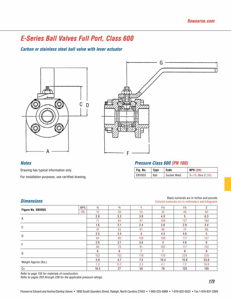
flowserve.com
173
Flowserve Edward and Anchor/Darling Valves • 1900 South Saunders Street, Raleigh, North Carolina 27603 • 1-800-225-6989 • 1-919-832-0525 • Fax 1-919-831-3369
A
C D D
F
G
F
NotesDrawing has typical information only.
For installation purposes, use certified drawing.
Pressure Class 600 (PN 100)Fig. No. Type Ends NPS(DN)
EBV95S Ball Socket Weld 1/2 (15) thru 2 (50)
E-Series Ball Valves Full Port, Class 600Carbon or stainless steel ball valve with lever actuator
DimensionsBlack numerals are in inches and pounds
Colored numerals are in millimeters and kilograms
FigureNo.EBV95SNPS 1/2 3/4 1 11/4 11/2 2DN 15 20 25 32 40 50
A2.8 3.3 3.8 4.3 5 6.371 84 97 109 127 160
C1.6 2.1 2.4 2.6 2.9 3.441 53 61 66 74 86
D2.5 3.4 4 4.3 4.6 564 86 102 109 117 127
F2.6 3.1 3.6 4 4.6 666 79 91 102 117 152
G6 6 7 7 9 9
152 152 178 178 229 229
Weight Approx (lbs.)2.9 4.7 7.3 10.4 15.8 23.81.3 6.2 3.3 4.7 7.2 10.8
Cv 16.5 27 50 78 120 195
Refer to page 155 for materials of construction. Refer to pages 203 through 238 for the applicable pressure ratings.
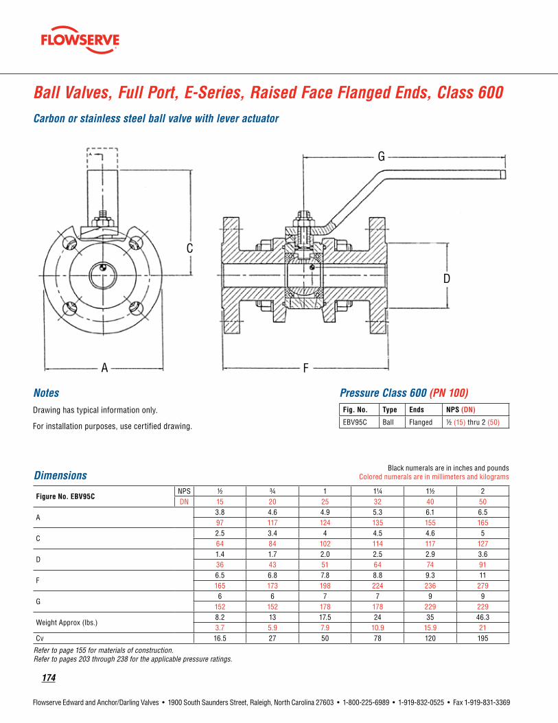
174
Flowserve Edward and Anchor/Darling Valves • 1900 South Saunders Street, Raleigh, North Carolina 27603 • 1-800-225-6989 • 1-919-832-0525 • Fax 1-919-831-3369
D
FA
G
C
NotesDrawing has typical information only.
For installation purposes, use certified drawing.
Pressure Class 600 (PN 100)Fig. No. Type Ends NPS(DN)
EBV95C Ball Flanged 1/2 (15) thru 2 (50)
DimensionsBlack numerals are in inches and pounds
Colored numerals are in millimeters and kilograms
FigureNo.EBV95CNPS 1/2 3/4 1 11/4 11/2 2DN 15 20 25 32 40 50
A3.8 4.6 4.9 5.3 6.1 6.597 117 124 135 155 165
C2.5 3.4 4 4.5 4.6 564 84 102 114 117 127
D1.4 1.7 2.0 2.5 2.9 3.636 43 51 64 74 91
F6.5 6.8 7.8 8.8 9.3 11165 173 198 224 236 279
G6 6 7 7 9 9
152 152 178 178 229 229
Weight Approx (lbs.)8.2 13 17.5 24 35 46.33.7 5.9 7.9 10.9 15.9 21
Cv 16.5 27 50 78 120 195
Refer to page 155 for materials of construction. Refer to pages 203 through 238 for the applicable pressure ratings.
Ball Valves, Full Port, E-Series, Raised Face Flanged Ends, Class 600Carbon or stainless steel ball valve with lever actuator

flowserve.com
175
Flowserve Edward and Anchor/Darling Valves • 1900 South Saunders Street, Raleigh, North Carolina 27603 • 1-800-225-6989 • 1-919-832-0525 • Fax 1-919-831-3369
Anchor/DarlingButterflyValves

176
Flowserve Edward and Anchor/Darling Valves • 1900 South Saunders Street, Raleigh, North Carolina 27603 • 1-800-225-6989 • 1-919-832-0525 • Fax 1-919-831-3369
High-Performance, Pressure-Assisted SeatingAnchor/Darling has applied our vast knowledge and experience in materials, manufacturing and design to our butterfly valves. Anchor/Darling butterfly valves incorporate proven performance features into an economically designed package. The result is a valve that offers the optimum combination of performance and life-cycle cost.
So when you need the best value in a proven butterfly valve, specify Flowserve Anchor/Darling.
Features That Ensure Dependable Operation• High operating pressures… to 1440 PSI.
• Excellent flow and throttling characteristics.
• High operating temperatures… to 500°F.
• High-performance, pressure-assisted bi-directional seat.
• Self-compensating seat design for maximum performance.
• Pressure-balanced shaft reduces thrust wear.
• Bubble-tight shut-off.
• Low torque for smooth and easy operation.
• Available with lift-to-unlock handle that automatically locks when released.
• Handle positions in 15-degree increments.
• Easily adaptable to automatic operation with electric, pneumatic or hydraulic actuators.
• Fourteen sizes from 3 inches to 48 inches inclusive.
• Suitable for vacuum service.
• Wide-band disc sealing area.
• Compact design cuts weight and space requirements.
• Heavy-duty corrosion-resistant shaft bearings.
• Adjustable shaft packing.
• Available in wafer, lugged, or flanged body design.
• Also available: Direct replacements for Contromatics butterfly valves.
Features and Description of Flowserve Anchor/Darling Butterfly Valves
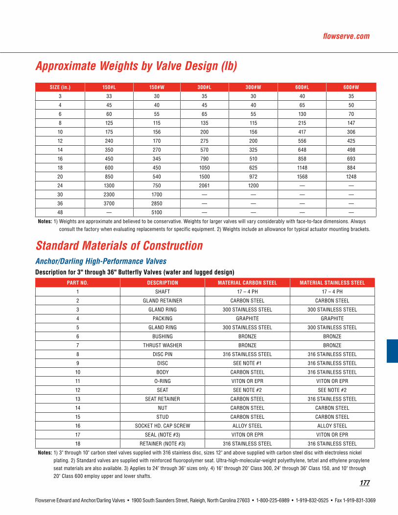
flowserve.com
177
Flowserve Edward and Anchor/Darling Valves • 1900 South Saunders Street, Raleigh, North Carolina 27603 • 1-800-225-6989 • 1-919-832-0525 • Fax 1-919-831-3369
Standard Materials of ConstructionAnchor/Darling High-Performance Valves Descriptionfor3"through36"ButterflyValves(waferandluggeddesign)
PARTNO. DESCRIPTION MATERIALCARBONSTEEL MATERIALSTAINLESSSTEEL
1 SHAFT 17 – 4 PH 17 – 4 PH
2 GLAND RETAINER CARBON STEEL CARBON STEEL
3 GLAND RING 300 STAINLESS STEEL 300 STAINLESS STEEL
4 PACKING GRAPHITE GRAPHITE
5 GLAND RING 300 STAINLESS STEEL 300 STAINLESS STEEL
6 BUSHING BRONZE BRONZE
7 THRUST WASHER BRONZE BRONZE
8 DISC PIN 316 STAINLESS STEEL 316 STAINLESS STEEL
9 DISC SEE NOTE #1 316 STAINLESS STEEL
10 BODY CARBON STEEL 316 STAINLESS STEEL
11 O-RING VITON OR EPR VITON OR EPR
12 SEAT SEE NOTE #2 SEE NOTE #2
13 SEAT RETAINER CARBON STEEL 316 STAINLESS STEEL
14 NUT CARBON STEEL CARBON STEEL
15 STUD CARBON STEEL CARBON STEEL
16 SOCKET HD. CAP SCREW ALLOY STEEL ALLOY STEEL
17 SEAL (NOTE #3) VITON OR EPR VITON OR EPR
18 RETAINER (NOTE #3) 316 STAINLESS STEEL 316 STAINLESS STEEL
Notes: 1) 3" through 10" carbon steel valves supplied with 316 stainless disc, sizes 12" and above supplied with carbon steel disc with electroless nickel plating. 2) Standard valves are supplied with reinforced fluoropolymer seat. Ultra-high-molecular-weight polyethylene, tefzel and ethylene propylene seat materials are also available. 3) Applies to 24" through 36" sizes only. 4) 16" through 20" Class 300, 24" through 36" Class 150, and 10" through 20" Class 600 employ upper and lower shafts.
Approximate Weights by Valve Design (lb)
SIZE(in.) 150#L 150#W 300#L 300#W 600#L 600#W
3 33 30 35 30 40 35
4 45 40 45 40 65 50
6 60 55 65 55 130 70
8 125 115 135 115 215 147
10 175 156 200 156 417 306
12 240 170 275 200 556 425
14 350 270 570 325 648 498
16 450 345 790 510 858 693
18 600 450 1050 625 1148 884
20 850 540 1500 972 1568 1248
24 1300 750 2061 1200 — —
30 2300 1700 — — — —
36 3700 2850 — — — —
48 — 5100 — — — —
Notes: 1) Weights are approximate and believed to be conservative. Weights for larger valves will vary considerably with face-to-face dimensions. Always consult the factory when evaluating replacements for specific equipment. 2) Weights include an allowance for typical actuator mounting brackets.
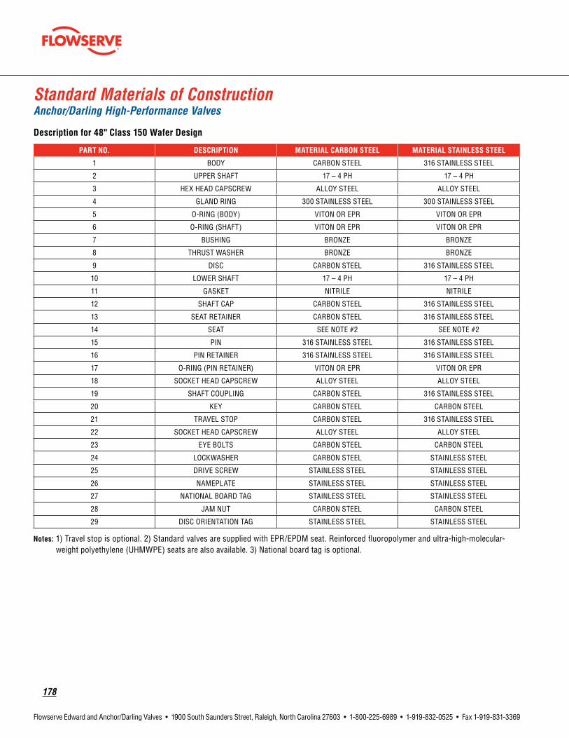
178
Flowserve Edward and Anchor/Darling Valves • 1900 South Saunders Street, Raleigh, North Carolina 27603 • 1-800-225-6989 • 1-919-832-0525 • Fax 1-919-831-3369
Standard Materials of ConstructionAnchor/Darling High-Performance Valves
Descriptionfor48"Class150WaferDesign
PARTNO. DESCRIPTION MATERIALCARBONSTEEL MATERIALSTAINLESSSTEEL
1 BODY CARBON STEEL 316 STAINLESS STEEL
2 UPPER SHAFT 17 – 4 PH 17 – 4 PH
3 HEX HEAD CAPSCREW ALLOY STEEL ALLOY STEEL
4 GLAND RING 300 STAINLESS STEEL 300 STAINLESS STEEL
5 O-RING (BODY) VITON OR EPR VITON OR EPR
6 O-RING (SHAFT) VITON OR EPR VITON OR EPR
7 BUSHING BRONZE BRONZE
8 THRUST WASHER BRONZE BRONZE
9 DISC CARBON STEEL 316 STAINLESS STEEL
10 LOWER SHAFT 17 – 4 PH 17 – 4 PH
11 GASKET NITRILE NITRILE
12 SHAFT CAP CARBON STEEL 316 STAINLESS STEEL
13 SEAT RETAINER CARBON STEEL 316 STAINLESS STEEL
14 SEAT SEE NOTE #2 SEE NOTE #2
15 PIN 316 STAINLESS STEEL 316 STAINLESS STEEL
16 PIN RETAINER 316 STAINLESS STEEL 316 STAINLESS STEEL
17 O-RING (PIN RETAINER) VITON OR EPR VITON OR EPR
18 SOCKET HEAD CAPSCREW ALLOY STEEL ALLOY STEEL
19 SHAFT COUPLING CARBON STEEL 316 STAINLESS STEEL
20 KEY CARBON STEEL CARBON STEEL
21 TRAVEL STOP CARBON STEEL 316 STAINLESS STEEL
22 SOCKET HEAD CAPSCREW ALLOY STEEL ALLOY STEEL
23 EYE BOLTS CARBON STEEL CARBON STEEL
24 LOCKWASHER CARBON STEEL STAINLESS STEEL
25 DRIVE SCREW STAINLESS STEEL STAINLESS STEEL
26 NAMEPLATE STAINLESS STEEL STAINLESS STEEL
27 NATIONAL BOARD TAG STAINLESS STEEL STAINLESS STEEL
28 JAM NUT CARBON STEEL CARBON STEEL
29 DISC ORIENTATION TAG STAINLESS STEEL STAINLESS STEEL
Notes: 1) Travel stop is optional. 2) Standard valves are supplied with EPR/EPDM seat. Reinforced fluoropolymer and ultra-high-molecular-weight polyethylene (UHMWPE) seats are also available. 3) National board tag is optional.

flowserve.com
179
Flowserve Edward and Anchor/Darling Valves • 1900 South Saunders Street, Raleigh, North Carolina 27603 • 1-800-225-6989 • 1-919-832-0525 • Fax 1-919-831-3369
Performance CharacteristicsAnchor/Darling High-Performance Valves
FrictionLossversusFlow–BasedonWater
Pressure/TemperatureCapabilityClass 150 and 300 ANSI Class 600 ANSI
Flow CharacteristicsCv values
Size(inches) 150 300
3 210 210
4 400 400
6 1150 1150
8 2100 2100
10 3410 3410
12 6525 4800
14 8400 6100
16 11000 7400
18 14800 9600
20 18700 11900
24 22000 *
30 30000 *
36 50000 *
48 95000 *

180
Flowserve Edward and Anchor/Darling Valves • 1900 South Saunders Street, Raleigh, North Carolina 27603 • 1-800-225-6989 • 1-919-832-0525 • Fax 1-919-831-3369
C
FA
B
H
Butterfly Valve, Class 150
DimensionsBlack numerals are in inches and pounds
Colored numerals are in millimeters and kilograms
FigureNo.BBF89VNPS 3 4 6 8 10DN 80 100 150 200 250
A5.1 6.8 8.9 10.9 13.1130 173 226 277 333
B5.9 7.1 8 10.5 13.1150 180 203 267 333
C12.5 15 17 19 25318 381 432 483 635
F1.9 2.1 2.3 2.5 2.848 53 58 64 71
H2.8 3.9 5.8 7.6 9.571 99 147 193 241
Dimensions are approximate and may vary. Always consult installation drawing. Refer to page 177 for materials of construction. Refer to pages 203 through 238 for the applicable pressure ratings.
Pressure Class 150 (PN 25)Fig. No. Type Ends NPS(DN)
BBF89V Butterfly Wafer 3 (80) thru 10 (250)

flowserve.com
181
Flowserve Edward and Anchor/Darling Valves • 1900 South Saunders Street, Raleigh, North Carolina 27603 • 1-800-225-6989 • 1-919-832-0525 • Fax 1-919-831-3369
Butterfly Valve, Class 150
C
FA
B
H
DimensionsBlack numerals are in inches and pounds
Colored numerals are in millimeters and kilograms
FigureNo.BBF89VNPS 12 14 16 18 20DN 300 350 400 450 500
A15.1 16.4 20 21.3 23.3384 417 508 541 592
B8.7 9.8 14.6 15.3 17.4221 249 371 389 442
C21.7 24.6 32.8 34.1 38.2551 625 833 866 970
F3.2 3.2 4.2 4.6 5.281 81 107 117 132
H11.8 12.9 14.8 16.7 18.7300 328 376 424 475
Dimensions are approximate and may vary. Always consult installation drawing. Refer to page 177 for materials of construction. Refer to pages 203 through 238 for the applicable pressure ratings.
Butterfly Valve, Class 150
Pressure Class 150 (PN 25)Fig. No. Type Ends NPS(DN)
BBF89V Butterfly Wafer 12 (300) thru 20 (500)

182
Flowserve Edward and Anchor/Darling Valves • 1900 South Saunders Street, Raleigh, North Carolina 27603 • 1-800-225-6989 • 1-919-832-0525 • Fax 1-919-831-3369
Butterfly Valve, Class 300
DimensionsBlack numerals are in inches and pounds
Colored numerals are in millimeters and kilograms
Figure No. CBF89V
NPS 3 4 6 8 10 12 14 16 18 20DN 80 100 150 200 250 300 350 400 450 500
A5.1 6.8 8.9 10.9 13.1 15.8 17.4 18.6 21.1 23.1130 173 226 277 333 401 442 472 536 587
B5.9 7.1 8 10.5 13.1 12.6 13.1 15.6 17.2 19.5150 180 203 267 333 320 333 396 437 495
C12.5 15 17 19 25 29.8 31 32.5 35.9 43.5318 381 432 483 635 757 787 826 912 1,105
F1.9 2.1 2.3 2.5 2.8 3.2 3.8 6.2 6.9 7.348 53 58 64 71 81 97 157 175 185
H2.8 3.9 5.8 7.6 9.5 11.4 12.8 14.8 16.6 18.571 99 147 193 241 290 325 376 422 470
Dimensions are approximate and may vary. Always consult installation drawing.Refer to page 177 for materials of construction. Refer to pages 203 through 238 for the applicable pressure ratings.
A F
C
B
H
Pressure Class 300 (PN 50)Fig. No. Type Ends NPS(DN)
CBF89V Butterfly Wafer 3 (80) thru 10 (250)

flowserve.com
183
Flowserve Edward and Anchor/Darling Valves • 1900 South Saunders Street, Raleigh, North Carolina 27603 • 1-800-225-6989 • 1-919-832-0525 • Fax 1-919-831-3369
A F
C
B
H
Butterfly Valve, Class 600
DimensionsBlack numerals are in inches and pounds
Colored numerals are in millimeters and kilograms
FigureNo.EBF89VNPS 3 4DN 80 100
A5.1 6.3130 160
B4.8 5.8122 147
C11.5 13.9292 353
F2.4 2.561 64
H2.9 3.674 91
Dimensions are approximate and may vary. Always consult installation drawing. Sizes 16” through 20” employ upper and lower shaftsRefer to page 177 for materials of construction. Refer to pages 203 through 238 for the applicable pressure ratings.
Pressure Class 600 (PN 110)Fig. No. Type Ends NPS(DN)
EBF89V Butterfly Wafer 3 (80) and 4 (100)

184
Flowserve Edward and Anchor/Darling Valves • 1900 South Saunders Street, Raleigh, North Carolina 27603 • 1-800-225-6989 • 1-919-832-0525 • Fax 1-919-831-3369
Butterfly Valve, Class 600
DimensionsBlack numerals are in inches and pounds
Colored numerals are in millimeters and kilograms
FigureNo.EBF89VNPS 6 8 10 12 14 16 18 20DN 150 200 250 300 350 400 450 500
A8.6 10.7 12.9 15.3 16.4 18.8 21.3 23.3218 272 328 389 417 478 541 592
B8.9 10.6 12.6 14.4 15.3 18.6 20.1 21.5226 269 320 366 389 472 511 546
C19.8 22.9 27.1 31 33.3 39.4 43.6 46.3503 582 688 787 846 1,001 1,107 1,176
F3.6 3.9 5.9 6.8 7.6 8.3 9.1 9.991 99 150 173 193 211 231 251
H5.8 7.3 9.8 11.4 12.5 14.3 16.1 18147 185 249 290 318 363 409 457
Dimensions are approximate and may vary. Always consult installation drawing.Refer to page 177 for materials of construction. Refer to pages 203 through 238 for the applicable pressure ratings.
A F
C
B
H

flowserve.com
185
Flowserve Edward and Anchor/Darling Valves • 1900 South Saunders Street, Raleigh, North Carolina 27603 • 1-800-225-6989 • 1-919-832-0525 • Fax 1-919-831-3369
DimensionsBlack numerals are in inches and pounds
Colored numerals are in millimeters and kilograms
Figure No. BBF89LNPS 3 4 6 8 10 12 14 16 18 20DN 80 100 150 200 250 300 350 400 450 500
A7.5 9 11 13.5 16 19 21 23.5 25 27.5191 229 279 343 406 483 533 597 635 699
B3.2 4.9 5.7 6.9 8.4 9.9 10.9 14.7 15.3 17.481 124 145 175 213 251 277 373 389 442
C9.8 12.4 14.9 18.1 19.5 22.9 25.6 32.8 34.1 38.2249 315 378 460 495 582 650 833 866 970
F2 2.1 2.3 2.5 2.8 3.2 3.2 4.1 4.6 5.151 53 58 64 71 81 81 104 117 130
H2.8 3.9 5.8 7.6 9.8 11.8 12.9 14.8 16.7 18.771 99 147 193 249 300 328 376 424 475
Refer to page 177 for materials of construction. Refer to pages 203 through 238 for the applicable pressure ratings.
Pressure Class 150 (PN 25)Fig. No. Type Ends NPS(DN)
BBF89L Butterfly Lugged 3 (80) thru 20 (500)
Butterfly Valve, Class 150
A
C
F
B
H

186
Flowserve Edward and Anchor/Darling Valves • 1900 South Saunders Street, Raleigh, North Carolina 27603 • 1-800-225-6989 • 1-919-832-0525 • Fax 1-919-831-3369
Butterfly Valve, Class 300
DimensionsBlack numerals are in inches and pounds
Colored numerals are in millimeters and kilograms
Figure No. CBL91LNPS 3 4 6 8 10 12 14 16 18 20DN 80 100 150 200 250 300 350 400 450 500
A8.3 10.0 12.5 15.0 17.5 20.5 23.0 25.5 28.0 30.5211 254 318 381 445 521 584 648 711 775
B5.9 5.4 7.6 8.4 11.1 12.6 13.1 15.6 17.4 19.5150 137 193 213 282 320 333 396 442 495
C12.5 12.9 16.9 19.6 26.8 29.8 31.0 32.5 35.9 43.1318 328 429 498 681 757 787 826 912 1,095
F1.9 2.1 2.3 2.5 2.8 3.2 3.8 6.2 6.9 7.348 53 58 64 71 81 97 157 175 185
H2.8 3.9 5.8 7.6 9.5 11.4 12.8 14.8 16.6 18.571 99 147 193 241 290 325 376 422 470
Refer to page 177 for materials of construction. Refer to pages 203 through 238 for the applicable pressure ratings.
Pressure Class 300 (PN 50)Fig. No. Type Ends NPS(DN)
CBL91L Butterfly Lugged 3 (80) thru 20 (500)
H
A
B
C

flowserve.com
187
Flowserve Edward and Anchor/Darling Valves • 1900 South Saunders Street, Raleigh, North Carolina 27603 • 1-800-225-6989 • 1-919-832-0525 • Fax 1-919-831-3369
Butterfly Valve, Class 600
DimensionsBlack numerals are in inches and pounds
Colored numerals are in millimeters and kilograms
FigureNo.EBF89LNPS 3 4DN 65 80
A8.3 10.8211 274
B4.8 5.8122 147
C11.5 13.9292 353
F2.4 2.561 64
H2.9 3.674 91
Dimensions are approximate and may vary. Always consult installation drawing.Refer to page 177 for materials of construction. Refer to pages 203 through 238 for the applicable pressure ratings.
Pressure Class 600 (PN 110)Fig. No. Type Ends NPS(DN)
EBF89L Butterfly Lugged 3 (80) thru 20 (500)
A F
C
B
H

188
Flowserve Edward and Anchor/Darling Valves • 1900 South Saunders Street, Raleigh, North Carolina 27603 • 1-800-225-6989 • 1-919-832-0525 • Fax 1-919-831-3369
Butterfly Valve, Class 600
DimensionsBlack numerals are in inches and pounds
Colored numerals are in millimeters and kilograms
FigureNo.EBF89LNPS 6 8 10 12 14 16 18 20DN 150 200 250 300 350 400 450 500
A14 16.5 20 22 23.8 27 29.3 32
356 419 508 559 605 686 744 813
B8.9 10.6 12.6 14.4 15.3 18.6 20.1 21.5226 269 320 366 389 472 511 546
C19.8 22.9 27.1 31 33.3 39.4 43.6 46.3503 582 688 787 846 1,001 1,107 1,176
F3.6 3.9 5.9 6.8 7.6 8.3 9.1 9.991 99 150 173 193 211 231 251
H5.8 7.3 9.8 11.4 12.5 14.3 16.1 18147 185 249 290 318 363 409 457
Dimensions are approximate and may vary. Always consult installation drawing.Refer to page 177 for materials of construction. Refer to pages 203 through 238 for the applicable pressure ratings.
A F
C
B
H

flowserve.com
189
Flowserve Edward and Anchor/Darling Valves • 1900 South Saunders Street, Raleigh, North Carolina 27603 • 1-800-225-6989 • 1-919-832-0525 • Fax 1-919-831-3369
SpecialApplicationsValves

190
Flowserve Edward and Anchor/Darling Valves • 1900 South Saunders Street, Raleigh, North Carolina 27603 • 1-800-225-6989 • 1-919-832-0525 • Fax 1-919-831-3369
As Flowserve-Raleigh’s products are supported with a highly experienced Technical Staff, the products can be adapted, modified or developed to handle special, critical applications. These products include multiple valve designs for Controlled Closure Check Valves and Excess Flow Check Valve. As new applications are identified, additional valve designs and products will be developed. Please consider Flowserve-Raleigh for all your critical nuclear valve applications, including those with new or special valve design requirements.
Contact your Flowserve-Raleigh Sales Manager for further information.
Special Applications Valves

flowserve.com
191
Flowserve Edward and Anchor/Darling Valves • 1900 South Saunders Street, Raleigh, North Carolina 27603 • 1-800-225-6989 • 1-919-832-0525 • Fax 1-919-831-3369
Controlled Closure Check Valve
Standard Features• Minimizes waterhammer effects on
postulated feedwater line break
• Computerized modeling verified by dynamic testing
The Flowserve Edward Controlled Closure Check Valve was developed and qualified to serve a function that no other previous check valve could handle. If a feedwater line should rupture in a nuclear power plant, the reversed flow from the reactor or steam generator out of the containment boundary must be contained. Conventional check valves would close rapidly, but not fast enough to prevent high reverse flow velocity; closure of the conventional valve would produce severe pressure surges due to waterhammer—possibly severe enough to produce rupture of other piping or equipment.
The Controlled Closure Check Valve is much like a Flite-Flow piston lift check valve, but it has an integral “dashpot”—a plate with a close-clearance fit around the rod connecting the disc and piston. Flow paths sized for individual applications limit the flow out of the dashpot and consequently control the valve closing speed. See pg. 235-237 for a discussion of waterhammer and a comparison of the controlled closure check valve with other types.
As the final design section is very dependent on the specific application, consult with your Flowserve sales representative for more design details for this valve configuration.

192
Flowserve Edward and Anchor/Darling Valves • 1900 South Saunders Street, Raleigh, North Carolina 27603 • 1-800-225-6989 • 1-919-832-0525 • Fax 1-919-831-3369
Excess Flow Check Valves – Sizes 1/2 through 2
Standard Features• ASME Section III Design
• SA351-CF8M, others available upon request
• Pressure classes up to 2500
• Metal to Metal or Soft Seats
• Butt Weld or Socket Weld
• Full Open Cv – 2.6
• Option – Position Indication

flowserve.com
193
Flowserve Edward and Anchor/Darling Valves • 1900 South Saunders Street, Raleigh, North Carolina 27603 • 1-800-225-6989 • 1-919-832-0525 • Fax 1-919-831-3369
Excess Flow Check Valves – Sizes 2-1/2 and Larger
Standard Features• ASME Section III Design
• SA216-WCB or SA351-CF8M, others available upon request
• Pressure classes up to 1500
• Metal to Metal or Soft Seats
• Flanged or Butt Weld End
• Valve remains in open position allowing flow over the disc
• Maintains a “keep warm” position when required during turbine pump normal warm up condition
• Valve disc moves to closed position based on required calculated flows
• The valve spring is engineered to hold the disc firm and avoid disc oscillation

194
Flowserve Edward and Anchor/Darling Valves • 1900 South Saunders Street, Raleigh, North Carolina 27603 • 1-800-225-6989 • 1-919-832-0525 • Fax 1-919-831-3369
Vacuum Breaker Valves – Sizes 2 and Larger
Standard Features• ASME Section III Design
• SA216-WCB or SA351-CF8M, others available upon request
• Pressure classes up to 1500
• Metal to Metal or Soft Seats
• Flanged or Butt Weld End

flowserve.com
195
Flowserve Edward and Anchor/Darling Valves • 1900 South Saunders Street, Raleigh, North Carolina 27603 • 1-800-225-6989 • 1-919-832-0525 • Fax 1-919-831-3369
Accessories/Actuators

196
Flowserve Edward and Anchor/Darling Valves • 1900 South Saunders Street, Raleigh, North Carolina 27603 • 1-800-225-6989 • 1-919-832-0525 • Fax 1-919-831-3369
Accessories
Globe, Angle, GateBy-Passes for Larger Cast Steel Valves (See Pg. 224)
Edward by-pass valves conform to the latest edition of MSS-SP45 of the Manufacturers Standardization Society of the Valve and Fittings Industry.
Unless otherwise specified when globe and angle valves are ordered with by-pass attached, the by-pass is attached to the left hand side of the valve when viewed from the overseat end.
Edward Forged Steel Valves for use as by-passes
SocketWeldingEndsOnly Class600 Class900 Class1500 Class2500 Series4500
For use on main stop valve Globe style, By-pass Fig. A848Y* Fig. D36224 Fig. D36224 Fig. D66224 Fig. D96224
For use on main stop-check valve Globe style, By-pass Fig. A868Y** Fig. D36264 Fig. D36264 Fig. D66264 Fig. D96264
* ALL MOTOR ACTUATED BY-PASS VALVES WILL BE FURNISHED WITH FIG. D36224. ** ALL MOTOR ACTUATED BY-PASS VALVES WILL BE FURNISHED WITH FIG. D36264.
Standard sizes of by-pass valves*
Main valve size (all pressures) 4 5 6 8 10 to 24
By-Pass size 1/2 3/4 3/4 3/4 1
* By-passes are provided only when specified. Standard sizes of by-pass valves are in accordance with the table above. Larger size by-pass valves will be furnished on special order.
Floor StandsEdward floor stands are cast iron or fabri-cated steel, and are designed and machined for accurate alignment. They are regularly furnished painted and are faced on bottom and drilled. Two heights, 20 and 32 inches, are available and can be furnished in indicat-ing or non-indicating types. Spur and motor control floor stands can be furnished to meet special conditions.
Chain WheelsA simple and efficient means of valve opera-tion from a lower level is provided by the use of chain wheels. They are fitted to the regular valve handwheels and are furnished complete with chain wheel and chain guide.
Valve ExtensionIllustration shows spur geared valve with extension stem for operation from below. Valves can also be furnished for extension operation above the valve. Larger size valves are also available with bevel gearing.

flowserve.com
197
Flowserve Edward and Anchor/Darling Valves • 1900 South Saunders Street, Raleigh, North Carolina 27603 • 1-800-225-6989 • 1-919-832-0525 • Fax 1-919-831-3369
Accessories – Cast and Forged SteelThe following “accessories” or “options” are available for Edward forged and cast steel valves. Consult your Edward valves sales representative for specific details.
Impactor HandwheelLarger size Edward valves (except gate valves) feature an Impactor handwheel that permits one or two men to develop several thousand ft. lbs. of torque for final valve closure — up to twelve times the force of an ordinary handwheel.
Impactogear®
The Edward Impactogear makes cycling of larger, high-pressure valves a one-man operation. Impactogear is an exclusive Edward ring gear and pinion assembly that is fastened to an Impactor handwheel and yoke. Using the mechanical advantage of gearing reduction, the assembly permits large valves to be cycled between full open and full closed with an air wrench operating off a nominal air supply. The Impactogear wrench connection is equipped with a safety wrench guard.
Custom PaintUnless otherwise specified Edward cast and forged (carbon or alloy) steel valves are painted with a high-temperature aluminum lacquer paint. Upon special order, Edward valves can be provided with customer specified paints or coatings.
Flow
Relief valve (J)External equalizer (DD)
Internal equalizer (DDI)
Automatic Center Cavity Equalizing Valve (ACCEV)
Drain or VentAll Edward cast steel valves can be supplied with drains and/or vents. A standard drain or vent pipe, six inches long, is socket welded to the valve body, or as specified by the customer.
External EqualizerA pipe that connects the bonnet cavity of the Equiwedge gate valve to the upstream side of the valve. See drawing and page 28 for additional information.
Internal EqualizerA hole drilled in the upstream seat ring of the Equiwedge Gate Valve for pressure equaliza-tion. See drawing and page 28 for additional information.
Relief ValveA pressure relief valve can be attached to the bonnet of the Equiwedge Gate Valve to protect against overpressurization, but not prevent pressure locking. See drawing and page 28 for additional information.
Automatic Center Cavity Equalizing ValveA fully automatic bonnet relief device that allows bi-directional seating even at low pressure differential. See drawing and page 198 for details.

198
Flowserve Edward and Anchor/Darling Valves • 1900 South Saunders Street, Raleigh, North Carolina 27603 • 1-800-225-6989 • 1-919-832-0525 • Fax 1-919-831-3369
ExamplesofaTypicalPackingLeakoff(left) andLiveLoadPackingGland(right)
Packing Chamber with Leakoff Typical Live Loading Arrangement
Accessories – Cast and Forged SteelThe following “accessories” or “options” are available for Flowserve Edward forged and cast steel valves. Consult your Flowserve Edward valves sales representative for specific details.
LeakoffThe left half of the schematic to the left depicts a typical Leakoff ar-rangement including lantern gland and upper and lower packing sets. This double-packing arrangement provides added protection against packing leaks.
Live LoadingThe right half of the schematic to the left depicts a typical live loaded packing assembly. The Belleville springs provide a constant packing load to compensate for packing consolidation and thermal effects.
Locking DevicesEdward valves can be provided with padlock and chain or other locking devices as specified.
Position Indicators & Limit SwitchesIf required, Edward valves can be fitted with a variety of position indicators and/or limit switches for remote indication.
Soft SeatsThis option is available for both forged and cast steel globe and check valves on a limited basis.
The disc face can be fitted with a soft seat or insert when drop tight sealing is a must. However, some limitations (temperature, differen-tial pressure, radiation) may apply. Consult your Flowserve Edward valves representative for more information.
Washout ConnectionsEdward cast steel valves can be fitted with special covers that incor-porate a pipe nipple to be used as a washout connection to introduce cleaning solutions, etc., for pipeline flushing.
Automatic Center Cavity Equalizing Valve (ACCEV)The Flowserve Edward ACCEV automatically relieves increasing center cavity pressure to the higher pressure end of the valve, while preventing leakage to the lower pressure end, solving pressure locking and bonnet over-pressur-ization problems that can occur in double-seated valves. The internal spring gives preferential connection to the designated upstream end of the valve. When system conditions result in the downstream pressure being higher than the upstream, the ball shifts so that the center cavity connects with the downstream end of the valve. The Edward ACCEV meets or exceeds MSS SP-61 for
tight shutoff in both directions. When furnished on an Edward Equiwedge gate valve, all of the necessary connections are made to the host valve and hydro-tested in our factory. No piping connections or testing are required by the user. The Edward ACCEV is available as a kit with necessary piping to be field installed on any existing Edward or other manufacturer’s valve, and can be readily dissas-sembled and repaired in-line in the event any maintenance is required. The Edward ACCEV is available in a commercial B16.34 version for general service and also in an ASME Section III N-Stamp version for nuclear applications.
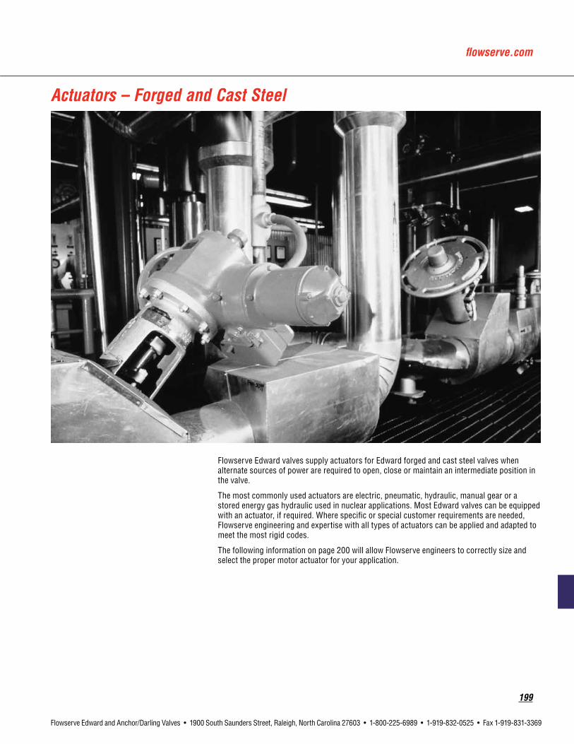
flowserve.com
199
Flowserve Edward and Anchor/Darling Valves • 1900 South Saunders Street, Raleigh, North Carolina 27603 • 1-800-225-6989 • 1-919-832-0525 • Fax 1-919-831-3369
Actuators – Forged and Cast Steel
Flowserve Edward valves supply actuators for Edward forged and cast steel valves when alternate sources of power are required to open, close or maintain an intermediate position in the valve.
The most commonly used actuators are electric, pneumatic, hydraulic, manual gear or a stored energy gas hydraulic used in nuclear applications. Most Edward valves can be equipped with an actuator, if required. Where specific or special customer requirements are needed, Flowserve engineering and expertise with all types of actuators can be applied and adapted to meet the most rigid codes.
The following information on page 200 will allow Flowserve engineers to correctly size and select the proper motor actuator for your application.

200
Flowserve Edward and Anchor/Darling Valves • 1900 South Saunders Street, Raleigh, North Carolina 27603 • 1-800-225-6989 • 1-919-832-0525 • Fax 1-919-831-3369
1.OPERATINGPRESSURES: A) PRESSURE UNDER SEAT = _____________________________________ psig B) PRESSURE OVER SEAT = ______________________________________ psig C) PRESSURE DIFFERENTIAL = ____________________________________ psig
2.MOTORPOWERSUPPLY*: A) AC = __________________ V. ___________________ HZ. ___________________ PH. _____________________ B) DC = _________________ V. *STANDARD VOLTAGE VARIANCE ± 10%, IF OTHERWISE, PLEASE INDICATE
3.LIMITSWITCH,TOTALQUANTITYOFCONTACTS = ________________________________________________________________
4.DOUBLETORQUESWITCHISSTANDARD.
5.CONTROLPOWERSUPPLYTOSWITCHCOMPARTMENT = __________________________________________________________
6.CLOSINGTIME: A) STANDARD (GLOBE VALVES APPROX. 4 IN./MIN., GATE VALVES APPROX. 12 IN./MIN. STEM SPEED.) B) SPECIAL ____________________ INDICATE REQUIRED CLOSING TIME: ___________________________
7.OPTIONALEQUIPMENT:(PLEASEINDICATEREQUIREDOPTIONS) A) MECHANICAL DIAL POSITION INDICATOR B) EXTRA TERMINALS C) REVERSING MOTOR CONTROLLER: ___________________ INTEGRAL OR ___________________ NON-INTEGRAL. D) PUSH-BUTTON STATION: ____________________________ INTEGRAL OR ___________________ NON-INTEGRAL. E) POSITION TRANSMITTER, INDICATE TYPE ___________________________________________________________ F) POSITION RECEIVER ____________________________________________________________________________ H) OTHERS ______________________________________________________________________________________ _______________________________________________________________________________________________ 8.AMBIENTCONDITIONS: ______________________________________________________________________________________
9.NEMARATING: STANDARD IS NEMA 4 (WEATHERPROOF), IF OTHERWISE, PLEASE LIST
_______________________________________________________________________________________________
10.STEMPOSITIONOFINSTALLEDVALVE: A) VERTICAL UP-RIGHT ______________________________________________ B) VERTICAL UP-SIDE DOWN __________________________________________ C) HORIZONTAL ____________________________________________________
Data in the Table above represents the minimum information that should be provided when ordering a valve equipped with a motor operator.
Required Information for Motor Actuators

flowserve.com
201
Flowserve Edward and Anchor/Darling Valves • 1900 South Saunders Street, Raleigh, North Carolina 27603 • 1-800-225-6989 • 1-919-832-0525 • Fax 1-919-831-3369
TablesandCharts
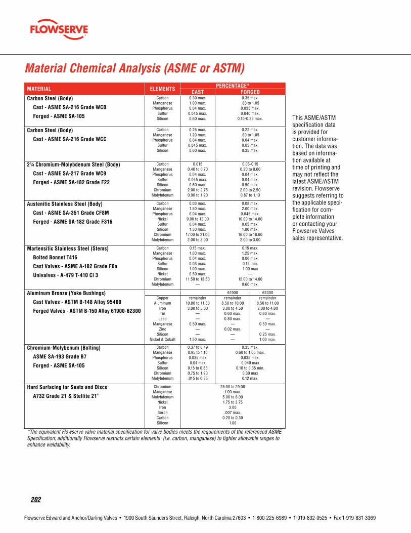
202
Flowserve Edward and Anchor/Darling Valves • 1900 South Saunders Street, Raleigh, North Carolina 27603 • 1-800-225-6989 • 1-919-832-0525 • Fax 1-919-831-3369
Material Chemical Analysis (ASME or ASTM)MATERIAL ELEMENTS PERCENTAGE*
CAST FORGEDCarbonSteel(Body)
Cast-ASMESA-216GradeWCB
Forged-ASMESA-105
CarbonManganesePhosphorus
SulfurSilicon
0.30 max.1.00 max.0.04 max.
0.045 max.0.60 max.
0.35 max..60 to 1.050.035 max.0.040 max.
0.10-0.35 max.
CarbonSteel(Body)
Cast-ASMESA-216GradeWCC
CarbonManganesePhosphorus
SulfurSilicon
0.25 max.1.20 max.0.04 max.
0.045 max.0.60 max.
0.22 max..60 to 1.050.04 max.0.05 max.0.35 max.
21/4Chromium-MolybdenumSteel(Body)
Cast-ASMESA-217GradeWC9
Forged-ASMESA-182GradeF22
CarbonManganesePhosphorus
SulfurSilicon
ChromiumMolybdenum
0.0150.40 to 0.700.04 max.
0.045 max.0.60 max.
2.00 to 2.750.90 to 1.20
0.05-0.150.30 to 0.600.04 max.0.04 max.0.50 max.
2.00 to 2.500.87 to 1.13
AusteniticStainlessSteel(Body)
Cast-ASMESA-351GradeCF8M
Forged-ASMESA-182GradeF316
CarbonManganesePhosphorus
NickelSulfurSilicon
ChromiumMolybdenum
0.03 max.1.50 max.0.04 max.
9.00 to 13.000.04 max.1.50 max.
17.00 to 21.002.00 to 3.00
0.08 max.2.00 max.
0.045 max.10.00 to 14.00
0.03 max.1.00 max.
16.00 to 18.002.00 to 3.00
MartensiticStainlessSteel(Stems)
BoltedBonnetT416
CastValves-ASMEA-182GradeF6a
Univalves-A-479T-410Cl3
CarbonManganese Phosphorus
SulfurSiliconNickel
ChromiumMolybdenum
0.15 max.1.00 max.0.04 max.0.03 max.1.00 max.0.50 max.
11.50 to 13.50—
0.15 max.1.25 max.0.06 max.0.15 min.1.00 max
—12.00 to 14.00
0.60 max.
AluminumBronze(YokeBushings)
CastValves-ASTMB-148Alloy95400
ForgedValves-ASTMB-150Alloy61900-62300
61900 62300Copper
AluminumIronTin
LeadManganese
ZincSilicon
Nickel & Cobalt
remainder10.00 to 11.503.00 to 5.00
——
0.50 max.——
1.50 max.
remainder8.50 to 10.003.00 to 4.500.60 max.0.80 max.
—0.02 max.
——
remainder8.50 to 11.002.00 to 4.000.60 max.
—0.50 max.
—0.25 max.1.00 max.
Chromium-Molybenum(Bolting)
ASMESA-193GradeB7
Forged-ASMESA-105
CarbonManganesePhosphorus
SulfurSilicon
ChromiumMolybdenum
0.37 to 0.490.95 to 1.100.035 max0.04 max
0.15 to 0.350.75 to 1.20.015 to 0.25
0.35 max.0.60 to 1.05 max.
0.035 max.0.040 max
0.10 to 0.35 min.0.30 max0.12 max.
HardSurfacingforSeatsandDiscs
A732Grade21&Stellite21®
ChromiumManganese
MolybdenumNickelIron
BoronCarbonSilicon
25.00 to 29.001.00 max.
5.00 to 6.001.75 to 3.75
3.00.007 max.
0.20 to 0.301.00
*The equivalent Flowserve valve material specification for valve bodies meets the requirements of the referenced ASME Specification; additionally Flowserve restricts certain elements (i.e. carbon, manganese) to tighter allowable ranges to enhance weldability.
This ASME/ASTM specification data is provided for customer informa-tion. The data was based on informa-tion available at time of printing and may not reflect the latest ASME/ASTM revision. Flowserve suggests referring to the applicable speci-fication for com-plete information or contacting your Flowserve Valves sales representative.
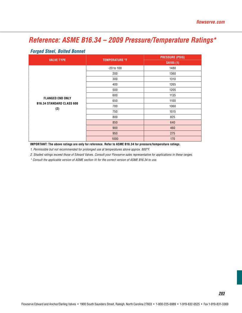
flowserve.com
203
Flowserve Edward and Anchor/Darling Valves • 1900 South Saunders Street, Raleigh, North Carolina 27603 • 1-800-225-6989 • 1-919-832-0525 • Fax 1-919-831-3369
Reference: ASME B16.34 – 2009 Pressure/Temperature Ratings*Forged Steel, Bolted Bonnet
VALVETYPE TEMPERATURE°FPRESSURE(PSIG)
SA105(1)
FLANGEDENDONLY
B16.34STANDARDCLASS600
(2)
-20 to 100 1480
200 1360
300 1310
400 1265
500 1205
600 1135
650 1100
700 1060
750 1015
800 825
850 640
900 460
950 275
1000 170
IMPORTANT:Theaboveratingsareonlyforreference. RefertoASMEB16.34forpressure/temperatureratings.
1. Permissible but not recommended for prolonged use at temperatures above approx. 800°F.
2. Shaded ratings exceed those of Edward Valves. Consult your Flowserve sales representative for applications in these ranges.
* Consult the applicable version of ASME section III for the correct version of ASME B16.34 to use.

204
Flowserve Edward and Anchor/Darling Valves • 1900 South Saunders Street, Raleigh, North Carolina 27603 • 1-800-225-6989 • 1-919-832-0525 • Fax 1-919-831-3369
Reference: ASME B16.34 – 2009 Pressure/Temperature Ratings (metric)*
Forged Steel, Bolted Bonnet 1 bar = 100 kPa = 14.50 psi
VALVETYPE TEMPERATURE°CPRESSURE(BAR)
SA105(1)
FLANGEDENDONLY
B16.34STANDARDCLASS600
(2)
-29 to 38 102.1
50 100.2
100 93.2
150 90.2
200 87.6
250 83.9
300 79.6
325 77.4
350 75.1
375 72.7
400 69.4
425 57.5
450 46.0
475 34.9
500 23.5
538 11.8
IMPORTANT:Theaboveratingsareonlyforreference. RefertoASMEB16.34forpressure/temperatureratings.
1. Permissible but not recommended for prolonged use at temperatures above approx. 427°C.
2. Shaded ratings exceed those of Edward Valves. Consult your Flowserve sales representative for applications in these ranges.
* Consult the applicable version of ASME section III for the correct version of ASME B16.34 to use.

flowserve.com
205
Flowserve Edward and Anchor/Darling Valves • 1900 South Saunders Street, Raleigh, North Carolina 27603 • 1-800-225-6989 • 1-919-832-0525 • Fax 1-919-831-3369
Reference: ASME B16.34 – 2009 Pressure/Temperature Ratings*
Cast Steel** (Gate, Globe & Check Valves)
MATERIAL TEMP°FPRESSURE(PSIG)
Class 150
Class 300
Class 600
Class 800
Class 900
Class 1500
Class 1878
Class 1888
SA216WCB
StandardClass
(1)(2)(3)
100 285 740 1480 1975 2220 3705 4635 4660
200 260 680 1360 1810 2035 3395 4250 4270
300 230 655 1310 1745 1965 3270 4095 4115
400 200 635 1265 1690 1900 3170 3970 3990
500 170 605 1205 1610 1810 3015 3775 3795
600 140 570 1135 1515 1705 2840 3555 3575
650 125 550 1100 1465 1650 2745 3435 3455
700 110 530 1060 1415 1590 2665 3330 3350
750 95 505 1015 1350 1520 2535 3175 3195
800 80 410 825 1100 1235 2055 2575 2590
850 65 320 640 850 955 1595 1995 2005
900 50 230 460 615 690 1150 1440 1445
950 35 135 275 365 410 685 860 865
1000 20 85 170 225 255 430 540 540
SA216WCB
SpecialClass
(1)(2)(3)
100 290 750 1500 2000 2250 3750 4695 4720
200 290 750 1500 2000 2250 3750 4695 4720
300 285 740 1480 1975 2220 3700 4635 4660
400 280 735 1465 1955 2200 3665 4585 4610
500 280 735 1465 1955 2200 3665 4585 4610
600 280 735 1465 1955 2200 3665 4585 4610
650 275 715 1430 1905 2145 3575 4475 4500
700 265 690 1380 1845 2075 3455 4325 4350
750 245 635 1270 1695 1905 3170 3970 3990
800 195 515 1030 1375 1545 2570 3220 3235
850 155 400 795 1060 1195 1995 2495 2510
900 110 285 575 765 860 1435 1800 1805
950 65 170 345 460 515 855 1070 1080
1000 40 105 215 285 320 535 670 675
IMPORTANT:Theaboveratingsareonlyforreference.RefertoASMEB16.34forpressure/temperatureratings
NOTES: 1. Flanged End Valve ratings are limited to Standard Class only.
2. Permissible but not recommended for prolonged usage above approximately 800°F.
3. Shaded ratings exceed those of Edward Valves. Consult your Flowserve sales representative for applications in these ranges.
* Consult the applicable version of ASME Section III for the correct version of ASME B16.34 to use.
** Pressure - Temperature ratings are from ASME B16.34 “Valves, Flanged, Threaded and Welding Ends”. Consult your Flowserve sales representative for
Pressure -Temperature ratings of materials not included in this catalog.

206
Flowserve Edward and Anchor/Darling Valves • 1900 South Saunders Street, Raleigh, North Carolina 27603 • 1-800-225-6989 • 1-919-832-0525 • Fax 1-919-831-3369
Reference: ASME B16.34 – 2009 Pressure/Temperature Ratings (metric)*
Cast Steel** (Gate, Globe & Check Valves)
MATERIAL TEMP°CPRESSURE(BAR)
Class 150
Class300
Class 600
Class 800
Class 900
Class 1500
Class 1878
Class 1888
SA216WCB
StandardClass
(1)(2)(3)
38 19.6 51.1 102.1 136.2 153.2 255.3 319.6 321.3
50 19.2 50.1 100.2 133.7 150.4 250.6 313.8 315.4
100 17.7 46.6 93.2 124.3 139.8 233 291.7 293.3
150 15.8 45.1 90.2 120.2 135.2 225.4 282.2 283.7
200 13.8 43.8 87.6 116.8 131.4 219 274.2 275.6
250 12.1 41.9 83.9 111.8 125.8 209.7 262.5 263.9
300 10.2 39.8 79.6 106.2 119.5 199.1 249.3 250.6
325 9.3 38.7 77.4 103.2 116.1 193.6 242.4 243.7
350 8.4 37.6 75.1 100.2 112.7 187.8 235.1 236.4
375 7.4 36.4 72.7 97 109.1 181.8 227.7 228.9
400 6.5 34.7 69.4 92.6 104.2 173.6 217.3 218.5
425 5.5 28.8 57.5 76.7 86.3 143.8 180.1 181
450 4.6 23 46 61.3 69 115 144 144.8
475 3.7 17.4 34.9 46.5 52.3 87.2 109.2 109.7
500 2.8 11.8 23.5 31.4 35.3 58.8 73.6 74
538 1.4 5.9 11.8 15.7 17.7 29.5 36.9 37.1
SA216WCB
SpecialClass
(1)(2)(3)
38 19.8 51.7 103.4 137.9 155.1 258.6 323.7 325.5
50 19.8 51.7 103.4 137.9 155.1 258.6 323.7 325.5
100 19.8 51.6 103.3 137.7 154.9 258.2 323.3 325
150 19.6 51 102.1 136.1 153.1 255.2 319.5 321.2
200 19.4 50.6 101.1 134.8 151.7 252.9 316.6 318.3
250 19.4 50.5 101.1 134.8 151.6 252.6 316.3 318
300 19.4 50.5 101.1 134.8 151.6 252.6 316.3 318
325 19.2 50.1 100.2 133.6 150.3 250.6 313.7 315.4
350 18.7 48.9 97.8 130.4 146.7 244.6 306.2 307.8
375 18.1 47.1 94.2 125.6 141.3 235.5 294.8 296.4
400 16.6 43.4 86.8 115.7 130.2 217 271.7 273.1
425 13.8 36 71.9 95.9 107.9 179.8 225.1 226.3
450 11 28.8 57.5 76.7 86.3 143.8 180 181
475 8.4 21.8 43.6 58.1 65.4 109 136.4 137.2
500 5.6 14.7 29.4 39.2 44.1 73.5 92 92.5
538 2.8 7.4 14.8 19.7 22.2 36.9 46.2 46.5
IMPORTANT:Theaboveratingsareonlyforreference.RefertoASMEB16.34forpressure/temperatureratings.
NOTES: 1. Flanged End Valve ratings are limited to Standard Class only. 2. Permissible but not recommended for prolonged usage above approximately 427°C. 3. Shaded ratings exceed those of Edward Valves. Consult your Flowserve sales representative for applications in these ranges.* Consult the applicable version of ASME Section III for the correct version of ASME B16.34 to use. ** Pressure - Temperature ratings are from ASME B16.34 “Valves, Flanged, Threaded and Welding Ends”. Consult your Flowserve sales representative for Pressure -Temperature ratings of materials not included in this catalog.

flowserve.com
207
Flowserve Edward and Anchor/Darling Valves • 1900 South Saunders Street, Raleigh, North Carolina 27603 • 1-800-225-6989 • 1-919-832-0525 • Fax 1-919-831-3369
Reference: ASME B16.34 – 2009 Pressure/Temperature Ratings*
Cast Steel** (Gate, Globe & Check Valves)
MATERIAL TEMP°CPRESSURE(PSIG)
Class 150
Class 300
Class 600
Class 800
Class 900
Class 1500
Class 1878
Class 1888
SA216WCC
StandardClass
(1)(2)(3)
100 290 750 1500 2000 2250 3750 4695 4720
200 260 750 1500 2000 2250 3750 4695 4720
300 230 730 1455 1940 2185 3640 4560 4585
400 200 705 1405 1875 2110 3520 4405 4430
500 170 665 1330 1775 1995 3325 4160 4185
600 140 605 1210 1615 1815 3025 3785 3805
650 125 590 1175 1570 1765 2940 3685 3700
700 110 555 1110 1480 1665 2775 3475 3495
750 95 505 1015 1350 1520 2535 3175 3195
800 80 410 825 1100 1235 2055 2575 2590
850 65 320 640 850 955 1595 1995 2005
900 50 225 445 595 670 1115 1395 1400
950 35 135 275 365 410 685 860 865
1000 20 85 170 225 255 430 540 540
SA216WCC
SpecialClass
(1)(2)(3)
100 290 750 1500 2000 2250 3750 4695 4720
200 290 750 1500 2000 2250 3750 4695 4720
300 290 750 1500 2000 2250 3750 4695 4720
400 290 750 1500 2000 2250 3750 4695 4720
500 290 750 1500 2000 2250 3750 4695 4720
600 290 750 1500 2000 2250 3750 4695 4720
650 290 750 1500 2000 2250 3750 4695 4720
700 280 715 1425 1900 2140 3565 4465 4485
750 280 635 1270 1695 1905 3170 3970 3990
800 255 515 1030 1375 1545 2570 3220 3235
850 200 400 795 1060 1195 1995 2495 2510
900 140 280 555 740 835 1395 1745 1755
950 85 170 345 460 515 855 1070 1080
1000 55 105 215 285 320 535 670 675
IMPORTANT:Theaboveratingsareonlyforreference.RefertoASMEB16.34forpressure/temperatureratings.
NOTES: 1. Flanged End Valve ratings are limited to Standard Class only and terminate at 1000°F. 2. Permissible but not recommended for prolonged usage above approximately 800°F. 3. Shaded ratings may require special trim and packing. Consult your Flowserve sales representative for applications in these ranges.
* Consult the applicable version of ASME Section III for the correct version of ASME B16.34 to use.
** Pressure - Temperature ratings are from ASME B16.34 “Valves, Flanged, Threaded and Welding Ends”. Consult your Flowserve sales representative for Pressure -Temperature ratings of materials not included in this catalog.

208
Flowserve Edward and Anchor/Darling Valves • 1900 South Saunders Street, Raleigh, North Carolina 27603 • 1-800-225-6989 • 1-919-832-0525 • Fax 1-919-831-3369
Reference: ASME B16.34 – 2009 Pressure/Temperature Ratings (metric)*
Cast Steel** (Gate, Globe & Check Valves)
MATERIAL TEMP°CPRESSURE(BAR)
Class 150
Class 300
Class 600
Class 800
Class 900
Class 1500
Class 1878
Class 1888
SA216WCC
StandardClass
(1)(2)(3)
38 19.8 51.7 103.4 137.9 155.1 258.6 323.7 325.5
50 19.5 51.7 103.4 137.9 155.1 258.6 323.7 325.5
100 17.7 51.5 103 137.4 154.6 257.6 322.5 324.3
150 15.8 50.2 100.3 133.8 150.5 250.8 314 315.7
200 13.8 48.6 97.2 129.6 145.8 243.2 304.5 306.1
250 12.1 46.3 92.7 123.6 139 231.8 290.2 291.7
300 10.2 42.9 85.7 114.3 128.6 214.4 268.3 269.8
325 9.3 41.4 82.6 110.2 124 206.6 258.7 260
350 8.4 40 80 106.7 120.1 200.1 250.5 251.9
375 7.4 37.8 75.7 100.9 113.5 189.2 236.9 238.1
400 6.5 34.7 69.4 92.6 104.2 173.6 217.3 218.5
425 5.5 28.8 57.5 76.7 86.3 143.8 180.1 181
450 4.6 23 46 61.3 69 115 144 144.8
475 3.7 17.1 34.2 45.6 51.3 85.4 106.9 107.5
500 2.8 11.6 23.2 30.9 34.7 57.9 72.5 72.9
538 1.4 5.9 11.8 15.7 17.7 29.5 36.9 37.1
SA216WCC
SpecialClass
(1)(2)(3)
38 20 51.7 103.4 137.9 155.1 258.6 323.7 325.5
50 20 51.7 103.4 137.9 155.1 258.6 323.7 325.5
100 20 51.7 103.4 137.9 155.1 258.6 323.7 325.5
150 20 51.7 103.4 137.9 155.1 258.6 323.7 325.5
200 20 51.7 103.4 137.9 155.1 258.6 323.7 325.5
250 20 51.7 103.4 137.9 155.1 258.6 323.7 325.5
300 20 51.7 103.4 137.9 155.1 258.6 323.7 325.5
325 20 51.7 103.4 137.9 155.1 258.6 323.7 325.5
350 19.8 51.1 102.2 136.3 153.3 255.5 319.9 321.6
375 19.3 48.4 96.7 129 145.1 241.9 302.8 304.4
400 19.3 43.4 86.8 115.7 130.2 217 271.7 273.1
425 18 36 71.9 95.9 107.9 179.8 225.1 226.3
450 14.4 28.8 57.5 76.7 86.3 143.8 180 181
475 10.7 21.4 42.7 57 64.1 106.8 133.7 134.4
500 7.2 14.5 29 38.6 43.4 72.4 90.7 91.1
538 3.7 7.4 14.8 19.7 22.2 36.9 46.2 46.5
IMPORTANT:Theaboveratingsareonlyforreference.RefertoASMEB16.34forpressure/temperatureratings.
NOTES: 1. Flanged End Valve ratings are limited to Standard Class only and terminate at 538°C.
2. Permissible but not recommended for prolonged usage above approximately 427°C.
3. Shaded ratings may require special trim and packing. Consult your Flowserve sales representative for applications in these ranges.
* Consult the applicable version of ASME Section III for the correct version of ASME B16.34 to use. ** Pressure - Temperature ratings are from ASME B16.34 “Valves, Flanged, Threaded and Welding Ends”. Consult your Flowserve sales representative for Pressure -Temperature ratings of materials not included in this catalog.

flowserve.com
209
Flowserve Edward and Anchor/Darling Valves • 1900 South Saunders Street, Raleigh, North Carolina 27603 • 1-800-225-6989 • 1-919-832-0525 • Fax 1-919-831-3369
Reference: ASME B16.34 – 2009 Pressure/Temperature Ratings*
Cast Steel** (Gate, Globe & Check Valves)
MATERIAL TEMP°CPRESSURE(PSIG)
Class 150
Class 300
Class 600
Class 900
Class 1500
Class 1878
Class 1888
SA217WC9
StandardClass
(1)(2)
100 290 750 1500 2250 3750 4695 4720
200 260 750 1500 2250 3750 4695 4720
300 230 730 1455 2185 3640 4560 4585
400 200 705 1410 2115 3530 4420 4440
500 170 665 1330 1995 3325 4160 4185
600 140 605 1210 1815 3025 3785 3805
650 125 590 1175 1765 2940 3685 3700
700 110 570 1135 1705 2840 3555 3575
750 95 530 1065 1595 2660 3330 3345
800 80 510 1015 1525 2540 3180 3195
850 65 485 975 1460 2435 3050 3065
900 50 450 900 1350 2245 2810 2825
950 35 385 755 1160 1930 2420 2430
1000 20 265 535 800 1335 1675 1680
1050 20 175 350 525 875 1095 1100
1100 20 110 220 330 550 690 690
SA217WC9
SpecialClass
(1)(2)
100 290 750 1500 2250 3750 4695 4720
200 290 750 1500 2250 3750 4695 4720
300 285 740 1480 2220 3695 4625 4650
400 280 730 1455 2185 3640 4555 4580
500 280 725 1450 2175 3620 4535 4555
600 275 720 1440 2165 3605 4515 4540
650 275 715 1430 2145 3580 4480 4505
700 270 705 1415 2120 3535 4425 4450
750 270 705 1415 2120 3535 4425 4450
800 270 705 1415 2120 3535 4425 4450
850 260 680 1355 2030 3385 4240 4260
900 230 600 1200 1800 3000 3755 3775
950 180 470 945 1415 2360 2955 2970
1000 130 335 670 1005 1670 2090 2105
1050 85 220 435 655 1095 1370 1375
1100 55 135 275 410 685 860 865
IMPORTANT:Theaboveratingsareonlyforreference.RefertoASMEB16.34forpressure/temperatureratings.
NOTES: 1. Flanged End Valve ratings are limited to Standard Class only and terminate at 1000°F.
2. Shaded ratings may require special trim and packing. Consult your Flowserve sales representative for applications in these ranges.
* Consult the applicable version of ASME Section III for the correct version of ASME B16.34 to use.
** Pressure - Temperature ratings are from ASME B16.34 “Valves, Flanged, Threaded and Welding Ends”. Consult your Flowserve sales representative for Pressure -Temperature ratings of materials not included in this catalog.

210
Flowserve Edward and Anchor/Darling Valves • 1900 South Saunders Street, Raleigh, North Carolina 27603 • 1-800-225-6989 • 1-919-832-0525 • Fax 1-919-831-3369
Reference: ASME B16.34 – 2009 Pressure/Temperature Ratings (metric)*
Cast Steel** (Gate, Globe & Check Valves)
MATERIAL TEMP°CPRESSURE(BAR)
Class 150
Class 300
Class 600
Class 900
Class 1500
Class 1878
Class 1888
SA217WC9
StandardClass
(1)(2)
38 19.8 51.7 103.4 155.1 258.6 323.7 325.5
50 19.5 51.7 103.4 155.1 258.6 323.7 325.5
100 17.7 51.5 103 154.6 257.6 322.5 324.3
150 15.8 50.3 100.3 150.6 250.8 314.1 315.8
200 13.8 48.6 97.2 145.8 243.4 304.6 306.3
250 12.1 46.3 92.7 139 231.8 290.2 291.7
300 10.2 42.9 85.7 128.6 214.4 268.3 269.8
325 9.3 41.4 82.6 124 206.6 258.7 260
350 8.4 40.3 80.4 120.7 201.1 251.8 253.2
375 7.4 38.9 77.6 116.5 194.1 242.9 244.2
400 6.5 36.5 73.3 109.8 183.1 229.1 230.4
425 5.5 35.2 70 105.1 175.1 219.1 220.3
450 4.6 33.7 67.7 101.4 169 211.6 212.8
475 3.7 31.7 63.4 95.1 158.2 198.2 199.2
500 2.8 28.2 56.5 84.7 140.9 176.5 177.4
538 1.4 18.4 36.9 55.3 92.2 115.4 116.1
550 1.4 15.6 31.3 46.9 78.2 97.9 98.4
575 1.4 10.5 21.1 31.6 52.6 65.9 66.2
600 1.4 6.9 13.8 20.7 34.4 43.1 43.3
IMPORTANT:Theaboveratingsareonlyforreference.RefertoASMEB16.34forpressure/temperatureratings.
NOTES: 1. Flanged End Valve ratings are limited to Standard Class only and terminate at 538°C. 2. Shaded ratings may require special trim and packing. Consult your Flowserve sales representative for applications in these ranges. * Consult the applicable version of ASME Section III for the correct version of ASME B16.34 to use.
** Pressure - Temperature ratings are from ASME B16.34 “Valves, Flanged, Threaded and Welding Ends”. Consult your Flowserve sales representative for Pressure -Temperature ratings of materials not included in this catalog.

flowserve.com
211
Flowserve Edward and Anchor/Darling Valves • 1900 South Saunders Street, Raleigh, North Carolina 27603 • 1-800-225-6989 • 1-919-832-0525 • Fax 1-919-831-3369
Reference: ASME B16.34 – 2009 Pressure/Temperature Ratings (metric)*
Cast Steel** (Gate, Globe & Check Valves)
MATERIAL TEMP°CPRESSURE(BAR)
Class 150
Class 300
Class 600
Class 900
Class 1500
Class 1878
Class 1888
SA217WC9
SpecialClass
(1)(2)
38 19.8 51.7 103.4 155.1 258.6 323.7 325.5
50 19.8 51.7 103.4 155.1 258.6 323.7 325.5
100 19.8 51.6 103.2 154.9 258.1 323.2 324.9
150 19.5 51 101.9 152.9 254.8 319 320.7
200 19.3 50.2 100.4 150.7 251.1 314.4 316.1
250 19.2 50 100 149.9 249.9 312.9 314.5
300 19.1 49.8 99.6 149.3 248.9 311.6 313.3
325 19 49.6 99.2 148.8 248 310.5 312.1
350 18.9 49.2 98.4 147.6 246 308 309.6
375 18.7 48.8 97.5 146.3 243.8 305.2 306.9
400 18.7 48.8 97.5 146.3 243.8 305.2 306.9
425 18.7 48.8 97.5 146.3 243.8 305.2 306.9
450 18.1 47.3 94.4 141.4 235.8 295.3 296.8
475 16.4 42.8 85.5 128.2 213.7 267.6 269
500 13.7 35.6 71.5 107.1 178.6 223.5 224.7
538 8.8 23 46.1 69.1 115.2 144.3 145
550 7.5 19.5 39.1 58.6 97.7 122.3 123
575 5 13.2 26.3 39.5 65.8 82.4 82.8
600 3.3 8.6 17.2 25.8 43 53.8 54.1
IMPORTANT:Theaboveratingsareonlyforreference.RefertoASMEB16.34forpressure/temperatureratings.
NOTES: 1. Flanged End Valve ratings are limited to Standard Class only and terminate at 538°C. 2. Shaded ratings may require special trim and packing. Consult your Flowserve sales representative for applications in these ranges. * Consult the applicable version of ASME Section III for the correct version of ASME B16.34 to use.
** Pressure - Temperature ratings are from ASME B16.34 “Valves, Flanged, Threaded and Welding Ends”. Consult your Flowserve sales representative for Pressure -Temperature ratings of materials not included in this catalog.
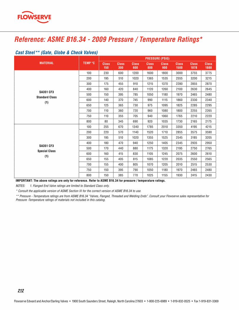
212
Flowserve Edward and Anchor/Darling Valves • 1900 South Saunders Street, Raleigh, North Carolina 27603 • 1-800-225-6989 • 1-919-832-0525 • Fax 1-919-831-3369
Reference: ASME B16.34 - 2009 Pressure / Temperature Ratings*
Cast Steel** (Gate, Globe & Check Valves)
MATERIAL TEMP°CPRESSURE(PSIG)
Class 150
Class 300
Class 600
Class 800
Class 900
Class 1500
Class 1878
Class 1888
SA351CF3
StandardClass
(1)
100 230 600 1200 1600 1800 3000 3755 3775
200 195 510 1020 1365 1535 2555 3200 3215
300 175 455 910 1215 1370 2280 2855 2870
400 160 420 840 1120 1260 2100 2630 2645
500 150 395 785 1050 1180 1970 2465 2480
600 140 370 745 990 1115 1860 2330 2340
650 125 365 730 975 1095 1825 2285 2295
700 110 360 720 960 1080 1800 2255 2265
750 110 355 705 940 1060 1765 2210 2220
800 80 345 690 920 1035 1730 2165 2175
SA351CF3
SpecialClass
(1)
100 255 670 1340 1785 2010 3350 4195 4215
200 220 570 1140 1520 1710 2855 3575 3590
300 195 510 1020 1355 1525 2545 3185 3205
400 180 470 940 1250 1405 2345 2935 2950
500 170 440 880 1175 1320 2195 2750 2765
600 160 415 830 1105 1245 2075 2600 2610
650 155 405 815 1085 1220 2035 2550 2565
700 155 400 805 1070 1205 2010 2515 2530
750 150 395 790 1050 1180 1970 2465 2480
800 150 385 770 1025 1155 1930 2415 2430
IMPORTANT:Theaboveratingsareonlyforreference.RefertoASMEB16.34forpressure/temperatureratings.
NOTES: 1. Flanged End Valve ratings are limited to Standard Class only.
* Consult the applicable version of ASME Section III for the correct version of ASME B16.34 to use.
** Pressure - Temperature ratings are from ASME B16.34 “Valves, Flanged, Threaded and Welding Ends”. Consult your Flowserve sales representative for Pressure -Temperature ratings of materials not included in this catalog.

flowserve.com
213
Flowserve Edward and Anchor/Darling Valves • 1900 South Saunders Street, Raleigh, North Carolina 27603 • 1-800-225-6989 • 1-919-832-0525 • Fax 1-919-831-3369
Reference: ASME B16.34 – 2009 Pressure/Temperature Ratings (metric)*
Cast Steel** (Gate, Globe & Check Valves)
MATERIAL TEMP°CPRESSURE(BAR)
Class 150
Class 300
Class 600
Class 800
Class 900
Class 1500
Class 1878
Class 1888
SA351CF3
StandardClass
(1)
38 15.9 41.4 82.7 110.3 124.1 206.8 258.9 260.3
50 15.3 40 80 106.7 120.1 200.1 250.5 251.9
100 13.3 34.8 69.6 92.8 104.4 173.9 217.7 218.9
150 12 31.4 62.8 83.7 94.2 157 196.5 197.6
200 11.2 29.2 58.3 77.8 87.5 145.8 182.5 183.5
250 10.5 27.5 54.9 73.2 82.4 137.3 171.9 172.8
300 10 26.1 52.1 69.5 78.2 130.3 163.1 164
325 9.3 25.5 51 67.9 76.4 127.4 159.5 160.3
350 8.4 25.1 50.1 66.8 75.2 125.4 157 157.8
375 7.4 24.8 49.5 66 74.3 123.8 155 155.8
400 6.5 24.3 48.6 64.8 72.9 121.5 152.1 152.9
425 5.5 23.9 47.7 63.6 71.6 119.3 149.4 150.1
SA351CF3
SpecialClass
(1)
38 17.7 46.2 92.3 123.1 138.5 230.9 289.1 290.6
50 17.1 44.7 89.3 119.1 134 223.3 279.6 281.1
100 14.9 38.8 77.7 103.6 116.5 194.1 243.1 244.3
150 13.4 35 70.1 93.4 105.1 175.2 219.3 220.5
200 12.5 32.5 65.1 86.8 97.6 162.7 203.7 204.8
250 11.8 30.7 61.3 81.8 92 153.3 191.9 192.9
300 11.2 29.1 58.2 77.6 87.3 145.5 182.1 183.1
325 10.9 28.4 56.9 75.8 85.3 142.2 178 179
350 10.7 28 56 74.6 83.9 139.9 175.2 176.1
375 10.6 27.6 55.2 73.7 82.9 138.1 172.9 173.8
400 10.4 27.1 54.3 72.4 81.4 135.6 169.8 170.7
425 10.2 26.6 53.3 71 79.9 133.1 166.7 167.6
IMPORTANT:Theaboveratingsareonlyforreference.RefertoASMEB16.34forpressure/temperatureratings.
NOTES: 1. Flanged End Valve ratings are limited to Standard Class only.
* Consult the applicable version of ASME Section III for the correct version of ASME B16.34 to use.
** Pressure - Temperature ratings are from ASME B16.34 “Valves, Flanged, Threaded and Welding Ends”. Consult your Flowserve sales representative for Pressure -Temperature ratings of materials not included in this catalog.

214
Flowserve Edward and Anchor/Darling Valves • 1900 South Saunders Street, Raleigh, North Carolina 27603 • 1-800-225-6989 • 1-919-832-0525 • Fax 1-919-831-3369
Reference: ASME B16.34 – 2009 Pressure/Temperature Ratings*
Cast Steel** (Gate, Globe & Check Valves)
MATERIAL TEMP.°CPRESSURE(PSIG)
Class150 Class300 Class600 Class800 Class900 Class1500 Class 1878 Class 1888
SA351CF8Standard
Class
(1)
100 275 720 1440 1920 2160 3600 4505 4530
200 230 600 1200 1600 1800 3000 3755 3775
300 205 540 1075 1435 1615 2690 3365 3385
400 190 495 995 1325 1490 2485 3110 3125
500 170 465 930 1240 1395 2330 2915 2930
600 140 440 885 1180 1325 2210 2765 2780
650 125 430 865 1150 1295 2160 2705 2720
700 110 420 845 1125 1265 2110 2645 2655
750 95 415 825 1100 1240 2065 2585 2600
800 80 405 810 1080 1215 2030 2540 2555
850 65 395 790 1055 1190 1980 2480 2490
900 50 390 780 1035 1165 1945 2435 2445
950 35 380 765 1020 1145 1910 2390 2405
1000 20 355 710 945 1065 1770 2215 2230
1050 20 325 650 865 975 1630 2040 2050
1100 20 255 515 685 770 1285 1610 1620
1150 20 205 410 545 615 1030 1290 1295
1200 20 165 330 440 495 825 1030 1035
1250 20 135 265 355 400 670 840 845
1300 20 115 225 300 340 565 710 710
1350 20 95 185 250 280 465 580 585
1400 20 75 150 200 225 380 475 475
1450 20 60 115 155 175 290 365 365
1500 15 40 85 110 125 205 260 260
IMPORTANT:Theaboveratingsareonlyforreference. RefertoASMEB16.34forpressure/temperatureratings.NOTES: 1. Flanged End Valve ratings are limited to Standard Class only and terminate at 1000°F. 2. Shaded ratings may require special trim and packing. Consult your Flowserve sales representative for applications in these ranges.
* Consult the applicable version of ASME Section III for the correct version of ASME B16.34 to use.
** Pressure - Temperature ratings are from ASME B16.34 “Valves, Flanged, Threaded and Welding Ends”. Consult your Flowserve sales representative for Pressure -Temperature ratings of materials not included in this catalog.
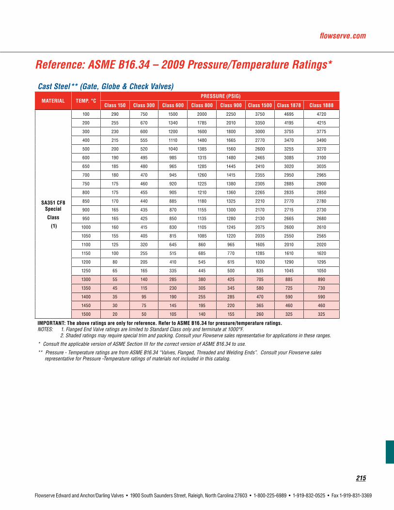
flowserve.com
215
Flowserve Edward and Anchor/Darling Valves • 1900 South Saunders Street, Raleigh, North Carolina 27603 • 1-800-225-6989 • 1-919-832-0525 • Fax 1-919-831-3369
Reference: ASME B16.34 – 2009 Pressure/Temperature Ratings*
Cast Steel** (Gate, Globe & Check Valves)
MATERIAL TEMP.°CPRESSURE(PSIG)
Class150 Class300 Class600 Class800 Class900 Class1500 Class 1878 Class 1888
SA351CF8Special
Class
(1)
100 290 750 1500 2000 2250 3750 4695 4720
200 255 670 1340 1785 2010 3350 4195 4215
300 230 600 1200 1600 1800 3000 3755 3775
400 215 555 1110 1480 1665 2770 3470 3490
500 200 520 1040 1385 1560 2600 3255 3270
600 190 495 985 1315 1480 2465 3085 3100
650 185 480 965 1285 1445 2410 3020 3035
700 180 470 945 1260 1415 2355 2950 2965
750 175 460 920 1225 1380 2305 2885 2900
800 175 455 905 1210 1360 2265 2835 2850
850 170 440 885 1180 1325 2210 2770 2780
900 165 435 870 1155 1300 2170 2715 2730
950 165 425 850 1135 1280 2130 2665 2680
1000 160 415 830 1105 1245 2075 2600 2610
1050 155 405 815 1085 1220 2035 2550 2565
1100 125 320 645 860 965 1605 2010 2020
1150 100 255 515 685 770 1285 1610 1620
1200 80 205 410 545 615 1030 1290 1295
1250 65 165 335 445 500 835 1045 1050
1300 55 140 285 380 425 705 885 890
1350 45 115 230 305 345 580 725 730
1400 35 95 190 255 285 470 590 590
1450 30 75 145 195 220 365 460 460
1500 20 50 105 140 155 260 325 325
IMPORTANT:Theaboveratingsareonlyforreference. RefertoASMEB16.34forpressure/temperatureratings.NOTES: 1. Flanged End Valve ratings are limited to Standard Class only and terminate at 1000°F. 2. Shaded ratings may require special trim and packing. Consult your Flowserve sales representative for applications in these ranges.
* Consult the applicable version of ASME Section III for the correct version of ASME B16.34 to use.
** Pressure - Temperature ratings are from ASME B16.34 “Valves, Flanged, Threaded and Welding Ends”. Consult your Flowserve sales representative for Pressure -Temperature ratings of materials not included in this catalog.

216
Flowserve Edward and Anchor/Darling Valves • 1900 South Saunders Street, Raleigh, North Carolina 27603 • 1-800-225-6989 • 1-919-832-0525 • Fax 1-919-831-3369
Reference: ASME B16.34 – 2009 Pressure/Temperature Ratings (metric)*
Cast Steel** (Gate, Globe & Check Valves)
MATERIAL TEMP.°CPRESSURE(BAR)
Class150 Class300 Class600 Class800 Class900 Class1500 Class 1878 Class 1888
SA351CF8Standard
Class
(1)(2)
38 19 49.6 99.3 132.4 148.9 248.2 310.8 312.4
50 18.3 47.8 95.6 127.5 143.5 239.1 299.4 300.9
100 15.7 40.9 81.7 109 122.6 204.3 255.7 257.1
150 14.2 37 74 98.7 111 185 231.6 232.9
200 13.2 34.5 69 91.9 103.4 172.4 215.8 217
250 12.1 32.5 65 86.7 97.5 162.4 203.3 204.4
300 10.2 30.9 61.8 82.4 92.7 154.6 193.5 194.6
325 9.3 30.2 60.4 80.6 90.7 151.1 189.2 190.2
350 8.4 29.6 59.3 79 88.9 148.1 185.4 186.4
375 7.4 29 58.1 77.4 87.1 145.2 181.8 182.7
400 6.5 28.4 56.9 75.8 85.3 142.2 178 179
425 5.5 28 56 74.7 84 140 175.3 176.2
450 4.6 27.4 54.8 73.1 82.2 137 171.5 172.5
475 3.7 26.9 53.9 71.8 80.8 134.7 168.6 169.5
500 2.8 26.5 53 70.7 79.5 132.4 165.8 166.7
538 1.4 24.4 48.9 65.2 73.3 122.1 152.9 153.7
550 1.4 23.6 47.1 62.8 70.7 117.8 147.5 148.3
575 1.4 20.8 41.7 55.6 62.5 104.2 130.5 131.2
600 1.4 16.9 33.8 45 50.6 84.4 105.7 106.2
625 1.4 13.8 27.6 36.8 41.4 68.9 86.3 86.7
650 1.4 11.3 22.5 30 33.8 56.3 70.5 70.9
675 1.4 9.3 18.7 24.9 28 46.7 58.5 58.8
700 1.4 8 16.1 21.4 24.1 40.1 50.2 50.5
725 1.4 6.8 13.5 18 20.3 33.8 42.3 42.5
750 1.4 5.8 11.6 15.4 17.3 28.9 36.2 36.3
775 1.4 4.6 9 12.1 13.7 22.8 28.5 28.7
800 1.2 3.5 7 9.3 10.5 17.4 21.9 22
816 1 2.8 5.9 7.7 8.6 14.1 17.8 17.9
IMPORTANT:Theaboveratingsareonlyforreference. RefertoASMEB16.34forpressure/temperatureratings.NOTES: 1. Flanged End Valve ratings are limited to Standard Class only and terminate at 538°C. 2. Shaded ratings may require special trim and packing. Consult your Flowserve sales representative for applications in these ranges.
* Consult the applicable version of ASME Section III for the correct version of ASME B16.34 to use.
** Pressure - Temperature ratings are from ASME B16.34 "Valves, Flanged, Threaded and Welding Ends". Consult your Flowserve sales representative for Pressure -Temperature ratings of materials not included in this catalog.

flowserve.com
217
Flowserve Edward and Anchor/Darling Valves • 1900 South Saunders Street, Raleigh, North Carolina 27603 • 1-800-225-6989 • 1-919-832-0525 • Fax 1-919-831-3369
Reference: ASME B16.34 – 2009 Pressure/Temperature Ratings (metric)*
Cast Steel** (Gate, Globe & Check Valves)
MATERIAL TEMP.°CPRESSURE(BAR)
Class150 Class300 Class600 Class800 Class900 Class1500 Class 1878 Class 1888
SA351CF8Special
Class
(1)(2)
38 19.8 51.7 103.4 137.9 155.1 258.6 323.7 325.5
50 19.4 50.5 101 134.7 151.5 252.5 316.1 317.8
100 17.5 45.6 91.2 121.6 136.8 228 285.5 287
150 15.8 41.3 82.6 110.1 123.9 206.5 258.6 259.9
200 14.8 38.5 77 102.6 115.4 192.4 240.9 242.2
250 13.9 36.3 72.5 96.7 108.8 181.3 227 228.2
300 13.2 34.5 69 92 103.5 172.5 216 217.1
325 12.9 33.7 67.5 90 101.2 168.7 211.2 212.3
350 12.7 33.1 66.1 88.2 99.2 165.3 207 208.1
375 12.4 32.4 64.8 86.4 97.2 162 202.8 203.9
400 12.2 31.7 63.5 84.6 95.2 158.7 198.7 199.8
425 12 31.2 62.5 83.3 93.7 156.2 195.6 196.6
450 11.7 30.6 61.2 81.6 91.8 153 191.5 192.5
475 11.5 30.1 60.1 80.2 90.2 150.3 188.2 189.2
500 11.3 29.6 59.1 78.8 88.7 147.8 185.1 186.1
538 11 28.6 57.3 76.4 85.9 143.1 179.2 180.1
550 10.9 28.4 56.8 75.7 85.1 141.9 177.7 178.6
575 10 26.1 52.1 69.5 78.2 130.3 163.1 164
600 8.1 21.1 42.2 56.3 63.3 105.5 132.1 132.8
625 6.6 17.2 34.5 46 51.7 86.2 107.9 108.5
650 5.4 14.1 28.2 37.5 42.2 70.4 88.1 88.6
675 4.5 11.7 23.4 31.2 35.1 58.4 73.1 73.5
700 4.1 10.7 21.3 28.4 32 53.3 66.8 67.1
725 3.5 9.2 18.5 24.6 27.7 46.2 57.8 58.2
750 2.8 7.4 14.8 19.7 22.1 36.7 46 46.2
775 2.2 5.8 11.4 15.3 17.2 28.5 35.7 35.9
800 1.8 4.4 8.8 11.7 13.2 22 27.5 27.7
816 1.4 3.4 7.2 9.5 10.7 17.9 22.3 22.4
IMPORTANT:Theaboveratingsareonlyforreference. RefertoASMEB16.34forpressure/temperatureratings.NOTES: 1. Flanged End Valve ratings are limited to Standard Class only and terminate at 538°C. 2. Shaded ratings may require special trim and packing. Consult your Flowserve sales representative for applications in these ranges.
* Consult the applicable version of ASME Section III for the correct version of ASME B16.34 to use.
** Pressure - Temperature ratings are from ASME B16.34 “Valves, Flanged, Threaded and Welding Ends”. Consult your Flowserve sales representative for Pressure -Temperature ratings of materials not included in this catalog.
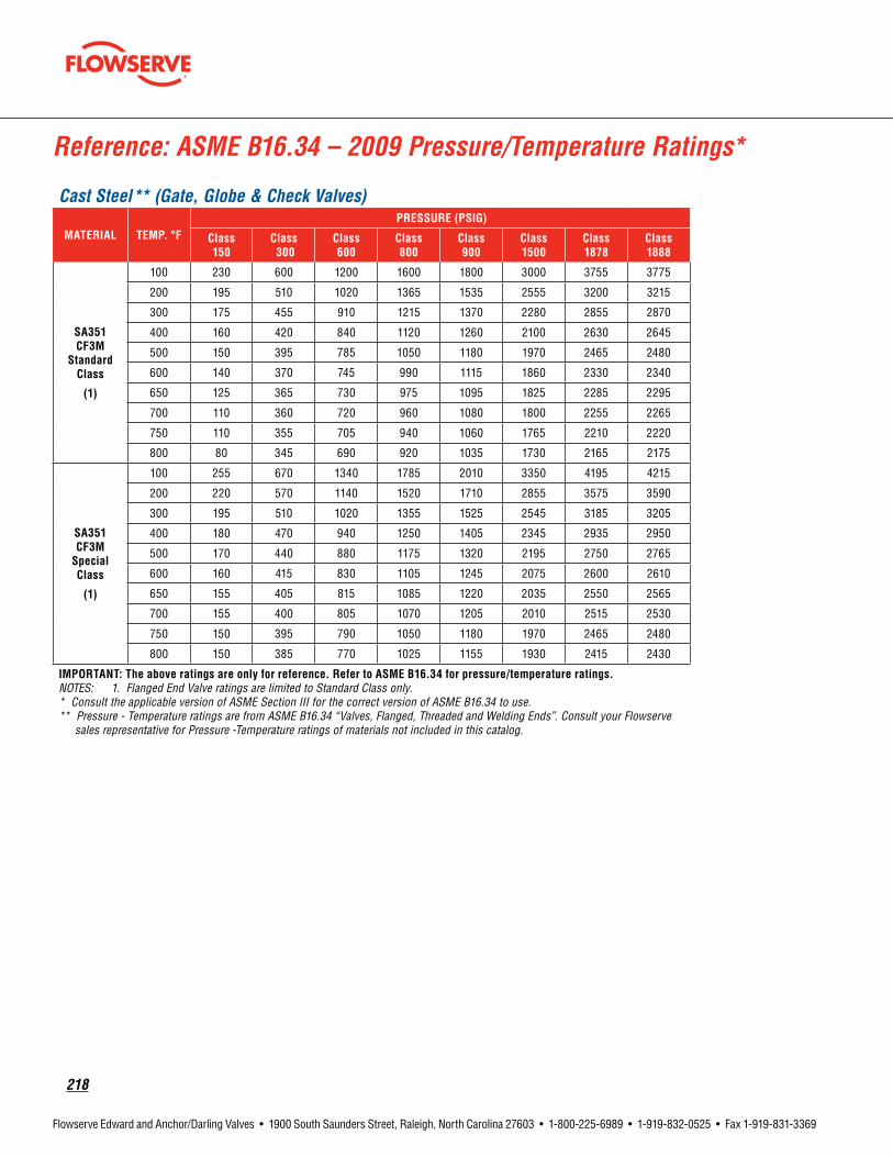
218
Flowserve Edward and Anchor/Darling Valves • 1900 South Saunders Street, Raleigh, North Carolina 27603 • 1-800-225-6989 • 1-919-832-0525 • Fax 1-919-831-3369
Reference: ASME B16.34 – 2009 Pressure/Temperature Ratings*
Cast Steel** (Gate, Globe & Check Valves)
MATERIAL TEMP.°FPRESSURE(PSIG)
Class 150
Class300
Class 600
Class 800
Class 900
Class 1500
Class 1878
Class 1888
SA351CF3M
StandardClass
(1)
100 230 600 1200 1600 1800 3000 3755 3775
200 195 510 1020 1365 1535 2555 3200 3215
300 175 455 910 1215 1370 2280 2855 2870
400 160 420 840 1120 1260 2100 2630 2645
500 150 395 785 1050 1180 1970 2465 2480
600 140 370 745 990 1115 1860 2330 2340
650 125 365 730 975 1095 1825 2285 2295
700 110 360 720 960 1080 1800 2255 2265
750 110 355 705 940 1060 1765 2210 2220
800 80 345 690 920 1035 1730 2165 2175
SA351CF3MSpecialClass
(1)
100 255 670 1340 1785 2010 3350 4195 4215
200 220 570 1140 1520 1710 2855 3575 3590
300 195 510 1020 1355 1525 2545 3185 3205
400 180 470 940 1250 1405 2345 2935 2950
500 170 440 880 1175 1320 2195 2750 2765
600 160 415 830 1105 1245 2075 2600 2610
650 155 405 815 1085 1220 2035 2550 2565
700 155 400 805 1070 1205 2010 2515 2530
750 150 395 790 1050 1180 1970 2465 2480
800 150 385 770 1025 1155 1930 2415 2430
IMPORTANT:Theaboveratingsareonlyforreference. RefertoASMEB16.34forpressure/temperatureratings.NOTES: 1. Flanged End Valve ratings are limited to Standard Class only. * Consult the applicable version of ASME Section III for the correct version of ASME B16.34 to use. ** Pressure - Temperature ratings are from ASME B16.34 “Valves, Flanged, Threaded and Welding Ends”. Consult your Flowserve sales representative for Pressure -Temperature ratings of materials not included in this catalog.

flowserve.com
219
Flowserve Edward and Anchor/Darling Valves • 1900 South Saunders Street, Raleigh, North Carolina 27603 • 1-800-225-6989 • 1-919-832-0525 • Fax 1-919-831-3369
Cast Steel** (Gate, Globe & Check Valves)
MATERIAL TEMP.°FPRESSURE(BAR)
Class 150
Class300
Class 600
Class 800
Class 900
Class 1500
Class 1878
Class 1888
SA351CF3Standard
Class
(1)
38 15.9 41.4 82.7 110.3 124.1 206.8 258.9 260.3
50 15.3 40 80 106.7 120.1 200.1 250.5 251.9
100 13.3 34.8 69.6 92.8 104.4 173.9 217.7 218.9
150 12 31.4 62.8 83.7 94.2 157 196.5 197.6
200 11.2 29.2 58.3 77.8 87.5 145.8 182.5 183.5
250 10.5 27.5 54.9 73.2 82.4 137.3 171.9 172.8
300 10 26.1 52.1 69.5 78.2 130.3 163.1 164
325 9.3 25.5 51 67.9 76.4 127.4 159.5 160.3
350 8.4 25.1 50.1 66.8 75.2 125.4 157 157.8
375 7.4 24.8 49.5 66 74.3 123.8 155 155.8
400 6.5 24.3 48.6 64.8 72.9 121.5 152.1 152.9
425 5.5 23.9 47.7 63.6 71.6 119.3 149.4 150.1
SA351CF3SpecialClass
(1)
38 17.7 46.2 92.3 123.1 138.5 230.9 289.1 290.6
50 17.1 44.7 89.3 119.1 134 223.3 279.6 281.1
100 14.9 38.8 77.7 103.6 116.5 194.1 243.1 244.3
150 13.4 35 70.1 93.4 105.1 175.2 219.3 220.5
200 12.5 32.5 65.1 86.8 97.6 162.7 203.7 204.8
250 11.8 30.7 61.3 81.8 92 153.3 191.9 192.9
300 11.2 29.1 58.2 77.6 87.3 145.5 182.1 183.1
325 10.9 28.4 56.9 75.8 85.3 142.2 178 179
350 10.7 28 56 74.6 83.9 139.9 175.2 176.1
375 10.6 27.6 55.2 73.7 82.9 138.1 172.9 173.8
400 10.4 27.1 54.3 72.4 81.4 135.6 169.8 170.7
425 10.2 26.6 53.3 71 79.9 133.1 166.7 167.6
IMPORTANT:Theaboveratingsareonlyforreference. RefertoASMEB16.34forpressure/temperatureratings.NOTES: 1. Flanged End Valve ratings are limited to Standard Class only. * Consult the applicable version of ASME Section III for the correct version of ASME B16.34 to use. ** Pressure - Temperature ratings are from ASME B16.34 “Valves, Flanged, Threaded and Welding Ends”. Consult your Flowserve sales representative for Pressure -Temperature ratings of materials not included in this catalog.
Reference: ASME B16.34 – 2009 Pressure/Temperature Ratings (metric)*
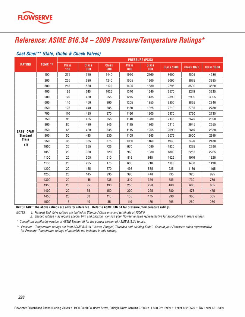
220
Flowserve Edward and Anchor/Darling Valves • 1900 South Saunders Street, Raleigh, North Carolina 27603 • 1-800-225-6989 • 1-919-832-0525 • Fax 1-919-831-3369
Reference: ASME B16.34 – 2009 Pressure/Temperature Ratings*
Cast Steel** (Gate, Globe & Check Valves)
RATING TEMP.°FPRESSURE(PSIG)
Class 150
Class 300
Class 600
Class 800
Class 900 Class1500 Class 1878 Class 1888
SA351CF8MStandard
Class
(1)
100 275 720 1440 1920 2160 3600 4505 4530
200 235 620 1240 1655 1860 3095 3875 3895
300 215 560 1120 1495 1680 2795 3500 3520
400 195 515 1025 1370 1540 2570 3215 3235
500 170 480 955 1275 1435 2390 2990 3005
600 140 450 900 1205 1355 2255 2825 2840
650 125 440 885 1180 1325 2210 2765 2780
700 110 435 870 1160 1305 2170 2720 2735
750 95 425 855 1140 1280 2135 2675 2690
800 80 420 845 1125 1265 2110 2645 2655
850 65 420 835 1115 1255 2090 2615 2630
900 50 415 830 1105 1245 2075 2600 2610
950 35 385 775 1030 1160 1930 2420 2430
1000 20 365 725 970 1090 1820 2275 2290
1050 20 360 720 960 1080 1800 2255 2265
1100 20 305 610 815 915 1525 1910 1920
1150 20 235 475 630 710 1185 1480 1490
1200 20 185 370 495 555 925 1160 1165
1250 20 145 295 390 440 735 920 925
1300 20 115 235 310 350 585 730 735
1350 20 95 190 255 290 480 600 605
1400 20 75 150 200 225 380 475 475
1450 20 60 115 155 175 290 365 365
1500 15 40 85 110 125 205 260 260
IMPORTANT:Theaboveratingsareonlyforreference.RefertoASMEB16.34forpressure/temperatureratings.
NOTES: 1. Flanged End Valve ratings are limited to Standard Class only and terminate at 1000°F. 2. Shaded ratings may require special trim and packing. Consult your Flowserve sales representative for applications in these ranges.
* Consult the applicable version of ASME Section III for the correct version of ASME B16.34 to use.
** Pressure - Temperature ratings are from ASME B16.34 “Valves, Flanged, Threaded and Welding Ends”. Consult your Flowserve sales representative for Pressure -Temperature ratings of materials not included in this catalog.

flowserve.com
221
Flowserve Edward and Anchor/Darling Valves • 1900 South Saunders Street, Raleigh, North Carolina 27603 • 1-800-225-6989 • 1-919-832-0525 • Fax 1-919-831-3369
Cast Steel** (Gate, Globe & Check Valves)
MATERIAL TEMP.°CPRESSURE(PSIG)
Class 150
Class 300
Class 600
Class 800
Class 900
Class 1500
Class 1878
Class 1888
SA351CF8MSpecial
Class
(1)
100 290 750 1500 2000 2250 3750 4695 4720
200 265 690 1380 1845 2075 3455 4325 4350
300 240 625 1250 1665 1870 3120 3905 3925
400 220 575 1145 1530 1720 2865 3585 3605
500 205 535 1065 1420 1600 2665 3335 3355
600 195 505 1005 1340 1510 2520 3155 3170
650 190 495 985 1315 1480 2465 3085 3100
700 185 485 970 1295 1455 2425 3035 3050
750 185 475 955 1270 1430 2385 2985 3000
800 180 470 945 1260 1415 2355 2950 2965
850 180 465 930 1245 1400 2330 2920 2935
900 180 465 925 1235 1390 2315 2900 2915
950 175 460 915 1220 1375 2290 2865 2880
1000 160 420 840 1120 1260 2105 2635 2650
1050 160 420 840 1120 1260 2105 2635 2650
1100 145 380 765 1020 1145 1905 2385 2400
1150 115 295 590 785 885 1480 1850 1860
1200 90 230 465 620 695 1155 1450 1455
1250 70 185 370 495 555 920 1150 1160
1300 55 145 290 385 435 730 915 920
1350 45 120 240 320 360 600 750 755
1400 35 95 190 255 285 470 590 590
1450 30 75 145 195 220 365 455 460
1500 20 50 105 140 155 260 325 325
IMPORTANT:Theaboveratingsareonlyforreference.RefertoASMEB16.34forpressure/temperatureratings.
NOTES: 1. Flanged End Valve ratings are limited to Standard Class only and terminate at 1000°F. 2. Shaded ratings may require special trim and packing. Consult your Flowserve sales representative for applications in these ranges.
* Consult the applicable version of ASME Section III for the correct version of ASME B16.34 to use.
** Pressure - Temperature ratings are from ASME B16.34 “Valves, Flanged, Threaded and Welding Ends”. Consult your Flowserve sales representative for Pressure -Temperature ratings of materials not included in this catalog.
Reference: ASME B16.34 – 2009 Pressure/Temperature Ratings*
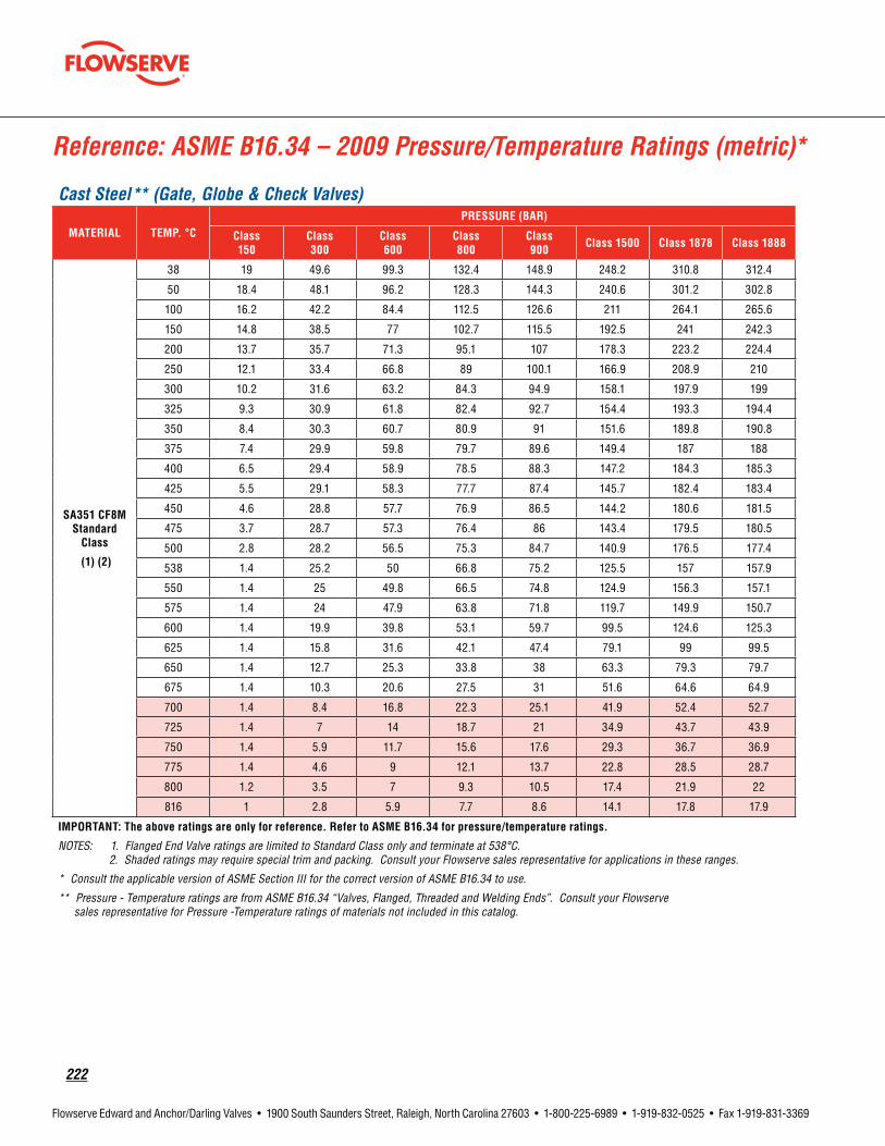
222
Flowserve Edward and Anchor/Darling Valves • 1900 South Saunders Street, Raleigh, North Carolina 27603 • 1-800-225-6989 • 1-919-832-0525 • Fax 1-919-831-3369
Reference: ASME B16.34 – 2009 Pressure/Temperature Ratings (metric)*
Cast Steel** (Gate, Globe & Check Valves)
MATERIAL TEMP.°CPRESSURE(BAR)
Class 150
Class 300
Class 600
Class 800
Class 900 Class1500 Class 1878 Class 1888
SA351CF8MStandard
Class
(1)(2)
38 19 49.6 99.3 132.4 148.9 248.2 310.8 312.4
50 18.4 48.1 96.2 128.3 144.3 240.6 301.2 302.8
100 16.2 42.2 84.4 112.5 126.6 211 264.1 265.6
150 14.8 38.5 77 102.7 115.5 192.5 241 242.3
200 13.7 35.7 71.3 95.1 107 178.3 223.2 224.4
250 12.1 33.4 66.8 89 100.1 166.9 208.9 210
300 10.2 31.6 63.2 84.3 94.9 158.1 197.9 199
325 9.3 30.9 61.8 82.4 92.7 154.4 193.3 194.4
350 8.4 30.3 60.7 80.9 91 151.6 189.8 190.8
375 7.4 29.9 59.8 79.7 89.6 149.4 187 188
400 6.5 29.4 58.9 78.5 88.3 147.2 184.3 185.3
425 5.5 29.1 58.3 77.7 87.4 145.7 182.4 183.4
450 4.6 28.8 57.7 76.9 86.5 144.2 180.6 181.5
475 3.7 28.7 57.3 76.4 86 143.4 179.5 180.5
500 2.8 28.2 56.5 75.3 84.7 140.9 176.5 177.4
538 1.4 25.2 50 66.8 75.2 125.5 157 157.9
550 1.4 25 49.8 66.5 74.8 124.9 156.3 157.1
575 1.4 24 47.9 63.8 71.8 119.7 149.9 150.7
600 1.4 19.9 39.8 53.1 59.7 99.5 124.6 125.3
625 1.4 15.8 31.6 42.1 47.4 79.1 99 99.5
650 1.4 12.7 25.3 33.8 38 63.3 79.3 79.7
675 1.4 10.3 20.6 27.5 31 51.6 64.6 64.9
700 1.4 8.4 16.8 22.3 25.1 41.9 52.4 52.7
725 1.4 7 14 18.7 21 34.9 43.7 43.9
750 1.4 5.9 11.7 15.6 17.6 29.3 36.7 36.9
775 1.4 4.6 9 12.1 13.7 22.8 28.5 28.7
800 1.2 3.5 7 9.3 10.5 17.4 21.9 22
816 1 2.8 5.9 7.7 8.6 14.1 17.8 17.9
IMPORTANT:Theaboveratingsareonlyforreference. RefertoASMEB16.34forpressure/temperatureratings.
NOTES: 1. Flanged End Valve ratings are limited to Standard Class only and terminate at 538°C. 2. Shaded ratings may require special trim and packing. Consult your Flowserve sales representative for applications in these ranges.
* Consult the applicable version of ASME Section III for the correct version of ASME B16.34 to use.
** Pressure - Temperature ratings are from ASME B16.34 “Valves, Flanged, Threaded and Welding Ends”. Consult your Flowserve sales representative for Pressure -Temperature ratings of materials not included in this catalog.

flowserve.com
223
Flowserve Edward and Anchor/Darling Valves • 1900 South Saunders Street, Raleigh, North Carolina 27603 • 1-800-225-6989 • 1-919-832-0525 • Fax 1-919-831-3369
Reference: ASME B16.34 – 2009 Pressure/Temperature Ratings (metric)*
Cast Steel** (Gate, Globe & Check Valves)
MATERIAL TEMP.°CPRESSURE(BAR)
Class 150
Class 300
Class 600
Class 800
Class 900 Class1500 Class 1878 Class 1888
SA351CF8MSpecial
Class
(1)(2)
38 19.8 51.7 103.4 137.9 155.1 258.6 323.7 325.5
50 19.5 50.8 101.6 135.5 152.5 254.1 318.1 319.8
100 18.1 47.1 94.2 125.6 141.3 235.5 294.8 296.4
150 16.5 43 85.9 114.6 128.9 214.8 268.9 270.4
200 15.3 39.8 79.6 106.1 119.4 199 249.2 250.5
250 14.3 37.3 74.5 99.4 111.8 186.3 233.2 234.5
300 13.5 35.3 70.6 94.1 105.9 176.4 220.9 222.1
325 13.2 34.5 68.9 91.9 103.4 172.3 215.7 216.9
350 13 33.8 67.7 90.2 101.5 169.2 211.9 213
375 12.8 33.3 66.7 88.9 100 166.7 208.7 209.8
400 12.6 32.9 65.7 87.6 98.6 164.3 205.7 206.8
425 12.5 32.5 65.1 86.8 97.6 162.6 203.6 204.7
450 12.3 32.2 64.4 85.9 96.6 161 201.6 202.6
475 12.3 32 64 85.3 96 160 200.3 201.4
500 12.2 31.7 63.4 84.5 95.1 158.6 198.6 199.6
538 11 29 57.9 77.2 86.9 145.1 181.6 182.6
550 11 29 57.9 77.2 86.9 145.1 181.6 182.6
575 10.9 28.6 57.1 76.2 85.7 143 179 180
600 9.5 24.9 49.8 66.3 74.6 124.4 155.7 156.6
625 7.6 19.8 39.5 52.7 59.3 98.8 123.7 124.4
650 6.1 15.8 31.7 42.2 47.5 79.1 99.1 99.6
675 4.9 12.9 25.8 34.4 38.7 64.5 80.8 81.2
700 4.4 11.4 22.8 30.5 34.3 57.1 71.5 71.9
725 3.7 9.5 19.1 25.4 28.6 47.7 59.7 60
750 2.8 7.4 14.8 19.7 22.1 36.7 46 46.2
775 2.2 5.8 11.4 15.3 17.2 28.5 35.7 35.9
800 1.8 4.4 8.8 11.7 13.2 22 27.5 27.7
816 1.4 3.4 7.2 9.5 10.7 17.9 22.3 22.4
IMPORTANT:Theaboveratingsareonlyforreference. RefertoASMEB16.34forpressure/temperatureratings.
NOTES: 1. Flanged End Valve ratings are limited to Standard Class only and terminate at 538°C. 2. Shaded ratings may require special trim and packing. Consult your Flowserve sales representative for applications in these ranges.
* Consult the applicable version of ASME Section III for the correct version of ASME B16.34 to use.
** Pressure - Temperature ratings are from ASME B16.34 “Valves, Flanged, Threaded and Welding Ends”. Consult your Flowserve sales representative for Pressure -Temperature ratings of materials not included in this catalog.

224
Flowserve Edward and Anchor/Darling Valves • 1900 South Saunders Street, Raleigh, North Carolina 27603 • 1-800-225-6989 • 1-919-832-0525 • Fax 1-919-831-3369
Reference: ASME B16.34 – 2009 Pressure/Temperature Ratings*
Forged Steel Univalves
MATERIAL TEMP.°CPRESSURE(PSIG)
Class600 Class1500(1) Class1690 Class2500
SA105Standard
Class
(2)(4)
100 1480 3705 4175 6170
200 1360 3395 3825 5655
300 1310 3270 3685 5450
400 1265 3170 3570 5280
500 1205 3015 3395 5025
600 1135 2840 3200 4730
650 1100 2745 3095 4575
700 1060 2665 3000 4425
750 1015 2535 2855 4230
800 825 2055 2315 3430
850 640 1595 1795 2655
900 460 1150 1295 1915
950 275 685 770 1145
1000 170 430 485 715
SA105Special
Class
(3)(4)
100 1500 3750 4225 6250
200 1500 3750 4225 6250
300 1480 3700 4170 6170
400 1465 3665 4130 6105
500 1465 3665 4130 6105
600 1465 3665 4130 6105
650 1430 3575 4030 5960
700 1380 3455 3895 5760
750 1270 3170 3570 5285
800 1030 2570 2895 4285
850 795 1995 2245 3320
900 575 1435 1615 2395
950 345 855 965 1430
1000 215 535 605 895
IMPORTANT:Theaboveratingsareonlyforreference. RefertoASMEB16.34forpressure/temperatureratings.
NOTES: 1. Standard Class: Flanged Ends Sizes 1/2 through 2-1/2, only. 2. Limited Class: Sizes 2-1/2 and smaller, butt weld and socket weld ends. Limited Class: Threaded ends limited to Sizes 1 and smaller, 1000°F maximum and pressure class 2500 maximum. 3. Special Class: Sizes 3 and 4 , Butt weld ends only. 4. Permissible but not recommended for prolonged usage above approximately 800°F. 5. Shaded ratings exceed those of Edward Valves. Consult your Flowserve sales representative for applications in these ranges.
* Consult the applicable version of ASME Section III for the correct version of ASME B16.34 to use.
** Pressure - Temperature ratings are from ASME B16.34 “Valves, Flanged, Threaded and Welding Ends”. Consult your Flowserve sales representative for Pressure -Temperature ratings of materials not included in this catalog.
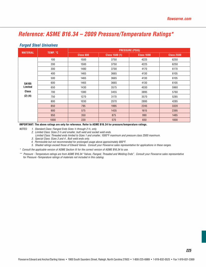
flowserve.com
225
Flowserve Edward and Anchor/Darling Valves • 1900 South Saunders Street, Raleigh, North Carolina 27603 • 1-800-225-6989 • 1-919-832-0525 • Fax 1-919-831-3369
Reference: ASME B16.34 – 2009 Pressure/Temperature Ratings*
Forged Steel Univalves
MATERIAL TEMP.°CPRESSURE(PSIG)
Class600 Class1500(1) Class1690 Class2500
SA105Limited
Class
(2)(4)
100 1500 3750 4225 6250
200 1500 3750 4225 6250
300 1480 3700 4170 6170
400 1465 3665 4130 6105
500 1465 3665 4130 6105
600 1465 3665 4130 6105
650 1430 3575 4030 5960
700 1380 3455 3895 5760
750 1270 3170 3570 5285
800 1030 2570 2895 4285
850 795 1995 2245 3320
900 575 1435 1615 2395
950 350 875 990 1485
1000 220 570 650 1000
IMPORTANT:Theaboveratingsareonlyforreference. RefertoASMEB16.34forpressure/temperatureratings.
NOTES: 1. Standard Class: Flanged Ends Sizes 1/2 through 2-1/2, only. 2. Limited Class: Sizes 2-1/2 and smaller, butt weld and socket weld ends. Limited Class: Threaded ends limited to Sizes 1 and smaller, 1000°F maximum and pressure class 2500 maximum. 3. Special Class: Sizes 3 and 4 , Butt weld ends only. 4. Permissible but not recommended for prolonged usage above approximately 800°F. 5. Shaded ratings exceed those of Edward Valves. Consult your Flowserve sales representative for applications in these ranges.
* Consult the applicable version of ASME Section III for the correct version of ASME B16.34 to use.
** Pressure - Temperature ratings are from ASME B16.34 “Valves, Flanged, Threaded and Welding Ends”. Consult your Flowserve sales representative for Pressure -Temperature ratings of materials not included in this catalog.

226
Flowserve Edward and Anchor/Darling Valves • 1900 South Saunders Street, Raleigh, North Carolina 27603 • 1-800-225-6989 • 1-919-832-0525 • Fax 1-919-831-3369
Reference: ASME B16.34 – 2009 Pressure/Temperature Ratings (metric)*
Forged Steel Univalves
MATERIAL TEMP.°CPRESSURE(BAR)
Class600 Class1500(1) Class1690 Class2500
SA105Standard
Class (2)(4)
38 102.1 255.3 287.6 425.5
50 100.2 250.6 282.3 417.7
100 93.2 233 262.5 388.3
150 90.2 225.4 253.9 375.6
200 87.6 219 246.7 365
250 83.9 209.7 236.3 349.5
300 79.6 199.1 224.3 331.8
325 77.4 193.6 218.1 322.6
350 75.1 187.8 211.6 313
375 72.7 181.8 204.8 303.1
400 69.4 173.6 195.6 289.3
425 57.5 143.8 162 239.7
450 46 115 129.6 191.7
475 34.9 87.2 98.2 145.3
500 23.5 58.8 66.2 97.9
538 11.8 29.5 33.2 49.2
SA105SpecialClass
(3)(4)
38 103.4 258.6 291.3 430.9
50 103.4 258.6 291.3 430.9
100 103.3 258.2 290.9 430.3
150 102.1 255.2 287.5 425.3
200 101.1 252.9 284.9 421.4
250 101.1 252.6 284.6 421.1
300 101.1 252.6 284.6 421.1
325 100.2 250.6 282.3 417.6
350 97.8 244.6 275.6 407.6
375 94.2 235.5 265.3 392.5
400 86.8 217 244.5 361.7
425 71.9 179.8 202.6 299.6
450 57.5 143.8 162 239.6
475 43.6 109 122.8 181.6
500 29.4 73.5 82.8 122.4
538 14.8 36.9 41.6 61.6
IMPORTANT:Theaboveratingsareonlyforreference. RefertoASMEB16.34forpressure/temperatureratings.
NOTES: 1. Standard Class: Flanged Ends Sizes 1/2 through 2-1/2, only. 2. Limited Class: Sizes 2-1/2 and smaller, butt weld and socket weld ends. Limited Class: Threaded ends limited to Sizes 1 and smaller, 538°C maximum and pressure class 2500 maximum. 3. Special Class: Sizes 3 and 4 , Butt weld ends only. 4. Permissible but not recommended for prolonged usage above approximately 427°C. 5. Shaded ratings exceed those of Edward Valves. Consult your Flowserve sales representative for applications in these ranges.
* Consult the applicable version of ASME Section III for the correct version of ASME B16.34 to use.
** Pressure - Temperature ratings are from ASME B16.34 “Valves, Flanged, Threaded and Welding Ends”. Consult your Flowserve sales representative for Pressure -Temperature ratings of materials not included in this catalog.

flowserve.com
227
Flowserve Edward and Anchor/Darling Valves • 1900 South Saunders Street, Raleigh, North Carolina 27603 • 1-800-225-6989 • 1-919-832-0525 • Fax 1-919-831-3369
Forged Steel Univalves
MATERIAL TEMP.°CPRESSURE(BAR)
Class600 Class1500(1) Class1690 Class2500
SA105Limited Class
(2)(4)
38 103.4 258.6 291.3 430.9
50 103.4 258.6 291.3 430.9
100 103.3 258.2 290.9 430.3
150 102.1 255.2 287.5 425.3
200 101.1 252.9 284.9 421.4
250 101.1 252.6 284.6 421.1
300 101.1 252.6 284.6 421.1
325 100.2 250.6 282.3 417.6
350 97.8 244.6 275.6 407.6
375 94.2 235.5 265.3 392.5
400 86.8 217 244.5 361.7
425 71.9 179.8 202.6 299.6
450 57.5 143.8 162 239.6
475 43.6 109 122.8 181.6
500 29.6 74.6 84.1 125.4
538 15.2 39.4 44.8 69
IMPORTANT:Theaboveratingsareonlyforreference. RefertoASMEB16.34forpressure/temperatureratings.
NOTES: 1. Standard Class: Flanged Ends Sizes 1/2 through 2-1/2, only. 2. Limited Class: Sizes 2-1/2 and smaller, butt weld and socket weld ends. Limited Class: Threaded ends limited to Sizes 1 and smaller, 538°C maximum and pressure class 2500 maximum. 3. Special Class: Sizes 3 and 4 , Butt weld ends only. 4. Permissible but not recommended for prolonged usage above approximately 427°C. 5. Shaded ratings exceed those of Edward Valves. Consult your Flowserve sales representative for applications in these ranges.
* Consult the applicable version of ASME Section III for the correct version of ASME B16.34 to use.
** Pressure - Temperature ratings are from ASME B16.34 “Valves, Flanged, Threaded and Welding Ends”. Consult your Flowserve sales representative for Pressure -Temperature ratings of materials not included in this catalog.
Reference: ASME B16.34 – 2009 Pressure/Temperature Ratings (metric)*

228
Flowserve Edward and Anchor/Darling Valves • 1900 South Saunders Street, Raleigh, North Carolina 27603 • 1-800-225-6989 • 1-919-832-0525 • Fax 1-919-831-3369
Reference: ASME B16.34 – 2009 Pressure/Temperature Ratings*
Forged Steel Univalves
MATERIAL TEMP.°CPRESSURE(PSIG)
Class1500(1) Class2500
SA182F22StandardClass
(4)(5)
100 3750 6250
200 3750 6250
300 3640 6070
400 3530 5880
500 3325 5540
600 3025 5040
650 2940 4905
700 2840 4730
750 2660 4430
800 2540 4230
850 2435 4060
900 2245 3745
950 1930 3220
1000 1335 2230
1050 875 1455
1100 550 915
1150 345 570
1200 205 345
SA182F22SpecialClass
(3)(4)(5)
100 3750 6250
200 3750 6250
300 3695 6160
400 3640 6065
500 3620 6035
600 3605 6010
650 3580 5965
700 3535 5895
750 3535 5895
800 3535 5895
850 3385 5645
900 3000 5000
950 2360 3930
1000 1670 2785
1050 1095 1820
1100 685 1145
1150 430 715
1200 255 430
IMPORTANT:Theaboveratingsareonlyforreference. RefertoASMEB16.34forpressure/temperatureratings.
NOTES: 1. Standard Class: Flanged Ends Sizes 1/2 through 2-1/2, only. Flanged ends terminate at 1000°F. 2. Limited Class: Sizes 2-1/2 and smaller, butt weld and socket weld ends. Limited Class: Threaded ends limited to Sizes 1 and smaller, 1000°F maximum and pressure class 2500 maximum. 3. Special Class: Sizes 3 and 4 , Butt weld ends only. 4. Permissible but not recommended for prolonged usage above approximately 1100°F. 5. Shaded ratings may require special trim and packing. Consult your Flowserve sales representative for applications in these ranges.
* Consult the applicable version of ASME Section III for the correct version of ASME B16.34 to use.
** Pressure - Temperature ratings are from ASME B16.34 “Valves, Flanged, Threaded and Welding Ends”. Consult your Flowserve sales representative for Pressure -Temperature ratings of materials not included in this catalog.

flowserve.com
229
Flowserve Edward and Anchor/Darling Valves • 1900 South Saunders Street, Raleigh, North Carolina 27603 • 1-800-225-6989 • 1-919-832-0525 • Fax 1-919-831-3369
Reference: ASME B16.34 – 2009 Pressure/Temperature Ratings*
Forged Steel Univalves
MATERIAL TEMP.°CPRESSURE(PSIG)
Class1500(1) Class2500
SA182F22Limited Class
(2)(5)
100 3750 6250
200 3750 6250
300 3695 6160
400 3640 6065
500 3620 6035
600 3605 6010
650 3580 5965
700 3535 5895
750 3535 5895
800 3535 5895
850 3385 5645
900 3000 5000
950 2410 4075
1000 1785 3120
1050 1170 2040
1100 730 1280
1150 460 800
1200 275 480
IMPORTANT:Theaboveratingsareonlyforreference. RefertoASMEB16.34forpressure/temperatureratings.
NOTES: 1. Standard Class: Flanged Ends Sizes 1/2 through 2-1/2, only. Flanged ends terminate at 1000°F. 2. Limited Class: Sizes 2-1/2 and smaller, butt weld and socket weld ends. Limited Class: Threaded ends limited to Sizes 1 and smaller, 1000°F maximum and pressure class 2500 maximum. 3. Special Class: Sizes 3 and 4 , Butt weld ends only. 4. Permissible but not recommended for prolonged usage above approximately 1100°F. 5. Shaded ratings may require special trim and packing. Consult your Flowserve sales representative for applications in these ranges.
* Consult the applicable version of ASME Section III for the correct version of ASME B16.34 to use.
** Pressure - Temperature ratings are from ASME B16.34 “Valves, Flanged, Threaded and Welding Ends”. Consult your Flowserve sales representative for Pressure -Temperature ratings of materials not included in this catalog. .

230
Flowserve Edward and Anchor/Darling Valves • 1900 South Saunders Street, Raleigh, North Carolina 27603 • 1-800-225-6989 • 1-919-832-0525 • Fax 1-919-831-3369
Reference: ASME B16.34 – 2009 Pressure/Temperature Ratings (metric)*
Forged Steel Univalves
RATING TEMP.°CPRESSURE(BAR)
Class1500(1) Class2500
SA182F22Standard
Class
(4)(5)
38 258.6 430.9
50 258.6 430.9
100 257.6 429.4
150 250.8 418.2
200 243.4 405.4
250 231.8 386.2
300 214.4 357.1
325 206.6 344.3
350 201.1 335.3
375 194.1 323.2
400 183.1 304.9
425 175.1 291.6
450 169 281.8
475 158.2 263.9
500 140.9 235
538 92.2 153.7
550 78.2 130.3
575 52.6 87.7
600 34.4 57.4
625 22.3 37.2
650 14.2 23.6
IMPORTANT:Theaboveratingsareonlyforreference. RefertoASMEB16.34forpressure/temperatureratings.
NOTES: 1. Standard Class: Flanged Ends Sizes 1/2 through 2-1/2, only. Flanged ends terminate at 538°C. 2. Limited Class: Sizes 2-1/2 and smaller, butt weld and socket weld ends. Limited Class: Threaded ends limited to Sizes 1 and smaller, 538°C maximum and pressure class 2500 maximum. 3. Special Class: Sizes 3 and 4 , Butt weld ends only. 4. Permissible but not recommended for prolonged usage above approximately 595°C. 5. Shaded ratings may require special trim and packing. Consult your Flowserve sales representative for applications in these ranges.
* Consult the applicable version of ASME Section III for the correct version of ASME B16.34 to use.
** Pressure - Temperature ratings are from ASME B16.34 “Valves, Flanged, Threaded and Welding Ends”. Consult your Flowserve sales representative for Pressure -Temperature ratings of materials not included in this catalog.
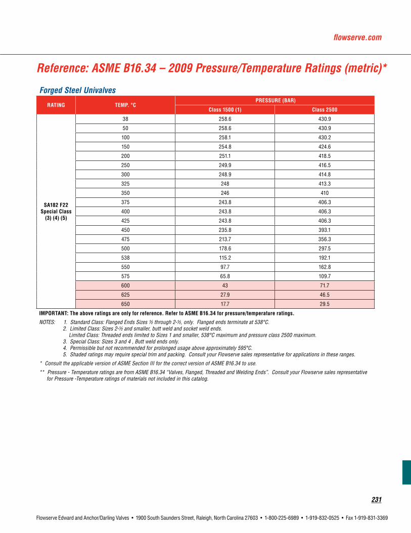
flowserve.com
231
Flowserve Edward and Anchor/Darling Valves • 1900 South Saunders Street, Raleigh, North Carolina 27603 • 1-800-225-6989 • 1-919-832-0525 • Fax 1-919-831-3369
Reference: ASME B16.34 – 2009 Pressure/Temperature Ratings (metric)*
Forged Steel Univalves
RATING TEMP.°CPRESSURE(BAR)
Class1500(1) Class2500
SA182F22SpecialClass(3)(4)(5)
38 258.6 430.9
50 258.6 430.9
100 258.1 430.2
150 254.8 424.6
200 251.1 418.5
250 249.9 416.5
300 248.9 414.8
325 248 413.3
350 246 410
375 243.8 406.3
400 243.8 406.3
425 243.8 406.3
450 235.8 393.1
475 213.7 356.3
500 178.6 297.5
538 115.2 192.1
550 97.7 162.8
575 65.8 109.7
600 43 71.7
625 27.9 46.5
650 17.7 29.5
IMPORTANT:Theaboveratingsareonlyforreference. RefertoASMEB16.34forpressure/temperatureratings.
NOTES: 1. Standard Class: Flanged Ends Sizes 1/2 through 2-1/2, only. Flanged ends terminate at 538°C. 2. Limited Class: Sizes 2-1/2 and smaller, butt weld and socket weld ends. Limited Class: Threaded ends limited to Sizes 1 and smaller, 538°C maximum and pressure class 2500 maximum. 3. Special Class: Sizes 3 and 4 , Butt weld ends only. 4. Permissible but not recommended for prolonged usage above approximately 595°C. 5. Shaded ratings may require special trim and packing. Consult your Flowserve sales representative for applications in these ranges.
* Consult the applicable version of ASME Section III for the correct version of ASME B16.34 to use.
** Pressure - Temperature ratings are from ASME B16.34 “Valves, Flanged, Threaded and Welding Ends”. Consult your Flowserve sales representative for Pressure -Temperature ratings of materials not included in this catalog.
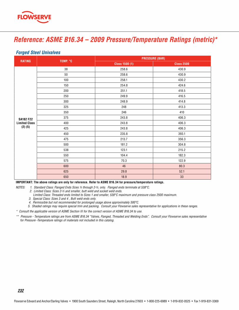
232
Flowserve Edward and Anchor/Darling Valves • 1900 South Saunders Street, Raleigh, North Carolina 27603 • 1-800-225-6989 • 1-919-832-0525 • Fax 1-919-831-3369
Reference: ASME B16.34 – 2009 Pressure/Temperature Ratings (metric)*
Forged Steel Univalves
RATING TEMP.°CPRESSURE(BAR)
Class1500(1) Class2500
SA182F22Limited Class
(2)(5)
38 258.6 430.9
50 258.6 430.9
100 258.1 430.2
150 254.8 424.6
200 251.1 418.5
250 249.9 416.5
300 248.9 414.8
325 248 413.3
350 246 410
375 243.8 406.3
400 243.8 406.3
425 243.8 406.3
450 235.8 393.1
475 213.7 356.3
500 181.2 304.8
538 123.1 215.2
550 104.4 182.3
575 70.3 122.9
600 46 80.3
625 29.8 52.1
650 18.9 33
IMPORTANT:Theaboveratingsareonlyforreference. RefertoASMEB16.34forpressure/temperatureratings.
NOTES: 1. Standard Class: Flanged Ends Sizes 1/2 through 2-1/2, only. Flanged ends terminate at 538°C. 2. Limited Class: Sizes 2-1/2 and smaller, butt weld and socket weld ends. Limited Class: Threaded ends limited to Sizes 1 and smaller, 538°C maximum and pressure class 2500 maximum. 3. Special Class: Sizes 3 and 4 , Butt weld ends only. 4. Permissible but not recommended for prolonged usage above approximately 595°C. 5. Shaded ratings may require special trim and packing. Consult your Flowserve sales representative for applications in these ranges.
* Consult the applicable version of ASME Section III for the correct version of ASME B16.34 to use.
** Pressure - Temperature ratings are from ASME B16.34 “Valves, Flanged, Threaded and Welding Ends”. Consult your Flowserve sales representative for Pressure -Temperature ratings of materials not included in this catalog.

flowserve.com
233
Flowserve Edward and Anchor/Darling Valves • 1900 South Saunders Street, Raleigh, North Carolina 27603 • 1-800-225-6989 • 1-919-832-0525 • Fax 1-919-831-3369
Reference: ASME B16.34 – 2009 Pressure/Temperature Ratings*
Forged Steel Univalves
MATERIAL TEMP.°CPRESSURE(PSIG)
Class1500(1) Class1690 Class2500
SA182F316Standard
Class
(4)
100 3600 4055 6000
200 3095 3485 5160
300 2795 3150 4660
400 2570 2895 4280
500 2390 2690 3980
600 2255 2540 3760
650 2210 2490 3680
700 2170 2445 3620
750 2135 2405 3560
800 2110 2380 3520
850 2090 2355 3480
900 2075 2340 3460
950 1930 2175 3220
1000 1820 2050 3030
1050 1800 2030 3000
1100 1525 1720 2545
1150 1185 1335 1970
1200 925 1045 1545
1250 735 830 1230
1300 585 660 970
1350 480 540 800
1400 380 430 630
1450 290 325 485
1500 205 230 345
Important:Theaboveratingsareonlyforreference.RefertoASMEB16.34forpressure/temperatureratings.NOTES: 1. Standard Class: Flanged Ends Sizes 1/2 through 2-1/2, only. Flanged ends terminate at 1000°F. 2. Limited Class: Sizes 2-1/2 and smaller, butt weld and socket weld ends. Limited Class: Threaded ends limited to Sizes 1 and smaller, 1000°F maximum and pressure class 2500 maximum. 3. Special Class: Sizes 3 and 4 , Butt weld ends only. 4. Shaded ratings may require special trim and packing. Consult your Flowserve sales representative for applications in these ranges.
* Consult the applicable version of ASME Section III for the correct version of ASME B16.34 to use.
** Pressure - Temperature ratings are from ASME B16.34 "Valves, Flanged, Threaded and Welding Ends". Consult your Flowserve sales representative for Pressure -Temperature ratings of materials not included in this catalog.

234
Flowserve Edward and Anchor/Darling Valves • 1900 South Saunders Street, Raleigh, North Carolina 27603 • 1-800-225-6989 • 1-919-832-0525 • Fax 1-919-831-3369
Reference: ASME B16.34 – 2009 Pressure/Temperature Ratings*
Forged Steel Univalves
MATERIAL TEMP.°CPRESSURE(PSIG)
Class1500(1) Class1690 Class2500
SA182F316SpecialClass
(3)(4)
100 3750 4225 6250
200 3455 3895 5760
300 3120 3515 5200
400 2865 3230 4775
500 2665 3000 4440
600 2520 2840 4195
650 2465 2775 4105
700 2425 2730 4040
750 2385 2685 3975
800 2355 2655 3930
850 2330 2625 3885
900 2315 2610 3860
950 2290 2580 3815
1000 2105 2370 3505
1050 2105 2370 3505
1100 1905 2145 3180
1150 1480 1665 2465
1200 1155 1300 1930
1250 920 1035 1535
1300 730 820 1215
1350 600 675 1000
1400 470 530 785
1450 365 410 605
1500 260 290 430
Important:Theaboveratingsareonlyforreference.RefertoASMEB16.34forpressure/temperatureratings.NOTES: 1. Standard Class: Flanged Ends Sizes 1/2 through 2-1/2, only. Flanged ends terminate at 1000°F. 2. Limited Class: Sizes 2-1/2 and smaller, butt weld and socket weld ends. Limited Class: Threaded ends limited to Sizes 1 and smaller, 1000°F maximum and pressure class 2500 maximum. 3. Special Class: Sizes 3 and 4 , Butt weld ends only. 4. Shaded ratings may require special trim and packing. Consult your Flowserve sales representative for applications in these ranges.
* Consult the applicable version of ASME Section III for the correct version of ASME B16.34 to use.
** Pressure - Temperature ratings are from ASME B16.34 "Valves, Flanged, Threaded and Welding Ends". Consult your Flowserve sales representative for Pressure -Temperature ratings of materials not included in this catalog.

flowserve.com
235
Flowserve Edward and Anchor/Darling Valves • 1900 South Saunders Street, Raleigh, North Carolina 27603 • 1-800-225-6989 • 1-919-832-0525 • Fax 1-919-831-3369
Reference: ASME B16.34 – 2009 Pressure/Temperature Ratings*
Forged Steel Univalves
MATERIAL TEMP.°CPRESSURE(PSIG)
Class1500(1) Class1690 Class2500
SA182F316Limited Class
(2)(4)
100 3750 4225 6250
200 3455 3895 5760
300 3120 3515 5200
400 2865 3230 4775
500 2665 3000 4440
600 2520 2840 4195
650 2465 2775 4105
700 2425 2730 4040
750 2385 2685 3975
800 2355 2655 3930
850 2330 2625 3885
900 2315 2610 3860
950 2290 2580 3815
1000 2105 2370 3505
1050 2105 2370 3505
1100 1945 2200 3300
1150 1580 1795 2760
1200 1235 1405 2160
1250 985 1120 1720
1300 780 885 1360
1350 640 730 1120
1400 500 570 880
1450 390 445 680
1500 280 315 480
Important:Theaboveratingsareonlyforreference.RefertoASMEB16.34forpressure/temperatureratings.NOTES: 1. Standard Class: Flanged Ends Sizes 1/2 through 2-1/2, only. Flanged ends terminate at 1000°F. 2. Limited Class: Sizes 2-1/2 and smaller, butt weld and socket weld ends. Limited Class: Threaded ends limited to Sizes 1 and smaller, 1000°F maximum and pressure class 2500 maximum. 3. Special Class: Sizes 3 and 4 , Butt weld ends only. 4. Shaded ratings may require special trim and packing. Consult your Flowserve sales representative for applications in these ranges.
* Consult the applicable version of ASME Section III for the correct version of ASME B16.34 to use.
** Pressure - Temperature ratings are from ASME B16.34 "Valves, Flanged, Threaded and Welding Ends". Consult your Flowserve sales representative for Pressure -Temperature ratings of materials not included in this catalog.

236
Flowserve Edward and Anchor/Darling Valves • 1900 South Saunders Street, Raleigh, North Carolina 27603 • 1-800-225-6989 • 1-919-832-0525 • Fax 1-919-831-3369
Reference: ASME B16.34 – 2009 Pressure/Temperature Ratings (metric)*
Forged Steel Univalves
MATERIAL TEMP.°CPRESSURE(BAR)
Class1500(1) Class1690 Class2500
SA182F316Standard
Class
(4)
38 248.2 279.6 413.7
50 240.6 271.1 400.9
100 211 237.7 351.6
150 192.5 216.9 320.8
200 178.3 200.9 297.2
250 166.9 188 278.1
300 158.1 178.1 263.5
325 154.4 174 257.4
350 151.6 170.8 252.7
375 149.4 168.3 249
400 147.2 165.8 245.3
425 145.7 164.2 242.9
450 144.2 162.5 240.4
475 143.4 161.5 238.9
500 140.9 158.8 235
538 125.5 141.3 208.9
550 124.9 140.7 208
575 119.7 134.9 199.5
600 99.5 112.1 165.9
625 79.1 89.1 131.8
650 63.3 71.3 105.5
675 51.6 58.1 86
700 41.9 47.2 69.8
725 34.9 39.3 58.2
750 29.3 33 48.9
775 22.8 25.7 38
800 17.4 19.6 29.2
816 14.1 15.9 23.8
Important:Theaboveratingsareonlyforreference.RefertoASMEB16.34forpressure/temperatureratings.NOTES: 1. Standard Class: Flanged Ends Sizes 1/2 through 2-1/2, only. Flanged ends terminate at 538°F. 2. Limited Class: Sizes 2-1/2 and smaller, butt weld and socket weld ends. Limited Class: Threaded ends limited to Sizes 1 and smaller, 538°F maximum and pressure class 2500 maximum. 3. Special Class: Sizes 3 and 4 , Butt weld ends only. 4. Shaded ratings may require special trim and packing. Consult your Flowserve sales representative for applications in these ranges.
* Consult the applicable version of ASME Section III for the correct version of ASME B16.34 to use.
** Pressure - Temperature ratings are from ASME B16.34 "Valves, Flanged, Threaded and Welding Ends". Consult your Flowserve sales representative for Pressure -Temperature ratings of materials not included in this catalog.

flowserve.com
237
Flowserve Edward and Anchor/Darling Valves • 1900 South Saunders Street, Raleigh, North Carolina 27603 • 1-800-225-6989 • 1-919-832-0525 • Fax 1-919-831-3369
Reference: ASME B16.34 – 2009 Pressure/Temperature Ratings (metric)*
Forged Steel Univalves
MATERIAL TEMP.°CPRESSURE(BAR)
Class1500(1) Class1690 Class2500
SA182F316SpecialClass
(3)(4)
38 258.6 291.3 430.9
50 254.1 286.3 423.5
100 235.5 265.3 392.4
150 214.8 242 358
200 199 224.2 331.7
250 186.3 209.9 310.4
300 176.4 198.8 294.1
325 172.3 194.1 287.2
350 169.2 190.7 282.1
375 166.7 187.8 277.9
400 164.3 185.1 273.8
425 162.6 183.2 271.1
450 161 181.4 268.3
475 160 180.3 266.6
500 158.6 178.7 264.3
538 145.1 163.5 241.7
550 145.1 163.5 241.7
575 143 161.1 238.3
600 124.4 140.2 207.3
625 98.8 111.3 164.7
650 79.1 89.1 131.9
675 64.5 72.7 107.5
700 57.1 64.3 95.2
725 47.7 53.7 79.5
750 36.7 41.4 61.2
775 28.5 32.1 47.6
800 22 24.8 36.6
816 17.9 20.1 29.6
Important:Theaboveratingsareonlyforreference.RefertoASMEB16.34forpressure/temperatureratings.NOTES: 1. Standard Class: Flanged Ends Sizes 1/2 through 2-1/2, only. Flanged ends terminate at 538°F. 2. Limited Class: Sizes 2-1/2 and smaller, butt weld and socket weld ends. Limited Class: Threaded ends limited to Sizes 1 and smaller, 538°F maximum and pressure class 2500 maximum. 3. Special Class: Sizes 3 and 4 , Butt weld ends only. 4. Shaded ratings may require special trim and packing. Consult your Flowserve sales representative for applications in these ranges.
* Consult the applicable version of ASME Section III for the correct version of ASME B16.34 to use.
** Pressure - Temperature ratings are from ASME B16.34 “Valves, Flanged, Threaded and Welding Ends”. Consult your Flowserve sales representative for Pressure -Temperature ratings of materials not included in this catalog.

238
Flowserve Edward and Anchor/Darling Valves • 1900 South Saunders Street, Raleigh, North Carolina 27603 • 1-800-225-6989 • 1-919-832-0525 • Fax 1-919-831-3369
Reference: ASME B16.34 – 2009 Pressure/Temperature Ratings (metric)*
Forged Steel Univalves
MATERIAL TEMP.°CPRESSURE(BAR)
Class1500(1) Class1690 Class2500
SA182F316Limited Class
(2)(4)
38 258.6 291.3 430.9
50 254.1 286.3 423.5
100 235.5 265.3 392.4
150 214.8 242 358
200 199 224.2 331.7
250 186.3 209.9 310.4
300 176.4 198.8 294.1
325 172.3 194.1 287.2
350 169.2 190.7 282.1
375 166.7 187.8 277.9
400 164.3 185.1 273.8
425 162.6 183.2 271.1
450 161 181.4 268.3
475 160 180.3 266.6
500 158.6 178.7 264.3
538 145.1 163.5 241.7
550 145.1 163.5 241.7
575 144.0 162.4 241.2
600 128.2 145.1 218.2
625 105.6 120.0 184.5
650 84.5 96.1 147.7
675 68.9 78.3 120.4
700 61 69.4 106.6
725 51 57.9 89
750 39.2 44.6 68.5
775 30.5 34.6 53.3
800 23.5 26.7 41
816 19.1 21.7 33.2
Important:Theaboveratingsareonlyforreference.RefertoASMEB16.34forpressure/temperatureratings.NOTES: 1. Standard Class: Flanged Ends Sizes 1/2 through 2-1/2, only. Flanged ends terminate at 538°F. 2. Limited Class: Sizes 2-1/2 and smaller, butt weld and socket weld ends. Limited Class: Threaded ends limited to Sizes 1 and smaller, 538°F maximum and pressure class 2500 maximum. 3. Special Class: Sizes 3 and 4 , Butt weld ends only. 4. Shaded ratings may require special trim and packing. Consult your Flowserve sales representative for applications in these ranges.
* Consult the applicable version of ASME Section III for the correct version of ASME B16.34 to use.
** Pressure - Temperature ratings are from ASME B16.34 “Valves, Flanged, Threaded and Welding Ends”. Consult your Flowserve sales representative for Pressure -Temperature ratings of materials not included in this catalog.

flowserve.com
239TechnicalInformation

240
Flowserve Edward and Anchor/Darling Valves • 1900 South Saunders Street, Raleigh, North Carolina 27603 • 1-800-225-6989 • 1-919-832-0525 • Fax 1-919-831-3369
• Seats – Industrial globe valves are available from various manufacturers with a broad variety of seat designs—flat or tapered, and integral or inserted (threaded or welded).
All Edward globe valves employ tapered seats with “area contact” under load to seal over minor imperfections. Many similar valves use “line-contact” seats that seal with less load when new but degrade rapidly if damaged at the seating line.
Except for hydraulic stop valves, all Edward globe valves employ integral (hardfaced) body seats to permit compact design and ensure that there can be no leakage “behind” the seat.
• DiscGuiding– Globe valve discs can be guided by either the stem or the body. When opened or closed under very high differential pressure, side load due to flow pushes a stem-guided disc eccentric to the seat and makes it difficult to obtain a seal. Under extreme conditions, the stem may bend.
All Edward globe valves employ body-guided discs that are held closely concentric with the body seat. Guiding is provided at both the top and bottom of the disc to form a fully body-guided disc piston. The bottom guide ring on the disc, a Flowserve Edward Valves innovation, minimizes flow behind the disc and minimizes the side load. These features make Edward globe valves well suited to “blowdown” applications in which there is a high differential pressure across the valve when it is partially open.
Since globe valves are not symmetrical with respect to flow, consideration must be given to the direction of flow and differential pres-sure. It should be noted that the direction of flow when open and differential pressure when closed may not be the same in all ap-plications (e.g., a block valve on a feed line may involve flow into a system when open but may need to prevent leakage out of the
system when closed). Users should consider both factors when deciding on the installation direction for a globe valve.
In most globe valve applications, pressure is under the seat when the valve is closed, and the flow is from under to over the seat (termed “flow to open” or “underseat flow”). In installations where the downstream pres-sure is zero or very low, this arrangement minimizes packing leakage problems. How-ever, handwheel or actuator effort to close the valve is high, because the stem must supply enough load to both overcome the differential pressure load across the seat area and ensure sufficient sealing load on the metal seat-contact surfaces. Since this flow direction is the most common for globe valves, the flow coefficients given in the Flow Performance section of this catalog are for underseat flow.
Globe valves can also be used with overseat flow and pressure (“flow to close”), but such applications require careful consideration. In systems with dirty line fluids, this arrange-ment could lead to trapping foreign material in locations where it would interfere with open-ing. With overseat pressure, the effort to close the valve is low, because closure and sealing are pressure-assisted. However, the effort to open the valve at high differential pressure is high, because the stem must overcome the pressure force to lift the disc (in small valves, the stem diameters approaching the seat diameter, this may not be a problem, because the pressure helps to lift the stem). Also, since the flow coefficients given in this catalog are for underseat flow, pressure-drop predictions may not be as accurate (pressure drop may be up to 10% higher with overseat flow).
While not designed as control valves and not recommended for continuous modulation, Edward globe valves are often used success-fully for manual or automatic control during limited periods of system operation (start-up, shutdown, etc.). Some manual valves are also used for continuous throttling or “trimming.” Inclined-bonnet valves, (e.g., Univalves and Flite-Flow valves) have an approximately linear flow characteristic (CV versus % open).
The Flow Performance section of this catalog covers only flow coefficients for fully open valves, but consult Flowserve concerning applications involving flow control. It should be understood that severe throttling at high-pressure drops involves high-energy dis-sipation, and serious problems (e.g., noise, vibration, cavitation, erosion) can develop if not carefully considered when a system is designed.
GateValvesA gate valve employs a closure member (or assembly) that opens and closes by moving perpendicular to the flow stream to engage two seats in the body. There are two basically different types of gate valves—parallel-side and wedge gate—in common use in pressure-piping systems, but there are many variations in design within each type.
As compared to glove valves, all gate valves offer straight-through flow paths that tend to produce less pressure drop than typical globe valves of the same nominal size. A Venturi gate valve with a smaller port versus a regular gate valve may offer a lower first cost as well as a size and weight saving if a minimized pressure drop is not required.
The Flow Performance section of this catalog gives comparable flow coefficients for Ed-ward Equiwedge® gate valves and all Edward globe stop valves. Evaluation of many valve applications has shown that inclined-bonnet globe valves are often competitive with gate valves when all factors are considered.
The stem in a gate valve does not have to overcome the full differential pressure load across the valve seat area to open or close the valve. Instead, it just has to overcome the friction force due to that load. Consequently, for operation at similar differential pressures, a gate valve generally requires less effort for actuation than a globe valve and can employ a smaller actuator when powered operation is required. However, a gate valve requires con-siderably greater stem travel than a conven-tional globe or angle valve (slightly greater than an inclined-bonnet globe valve), so a somewhat longer time may be required for action.
The two body seats – the common feature in all ordinary gate valves – can be both an ad-vantage and a disadvantage. Most gate valves are primarily “downstream-sealing,” because the closure member is pressure-energized in that direction. However, the upstream seating surfaces may help by limiting leakage if the
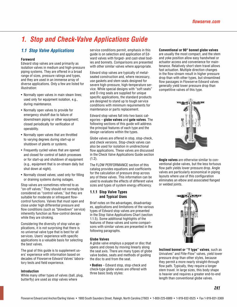
flowserve.com
241
Flowserve Edward and Anchor/Darling Valves • 1900 South Saunders Street, Raleigh, North Carolina 27603 • 1-800-225-6989 • 1-919-832-0525 • Fax 1-919-831-3369
1.1 Stop Valve Applications
ForewordEdward stop valves are used primarily as isolation valves in medium and high-pressure piping systems. They are offered in a broad range of sizes, pressure ratings and types, and they are used in an immense array of diverse applications. Only a few are listed for illustration:
• Normally open valves in main steam lines; used only for equipment isolation, e.g., during maintenance.
• Normally open valves to provide for emergency shutoff due to failure of downstream piping or other equipment; closed periodically for verification of operability.
• Normally open valves that are throttled to varying degrees during start-up or shutdown of plants or systems.
• Frequently cycled valves that are opened and closed for control of batch processes or for start-up and shutdown of equipment (e.g., equipment that is on-stream daily but shut down at night).
• Normally closed valves; used only for filling or draining systems during outages.
Stop valves are sometimes referred to as “on-off valves.” They should not normally be considered as “control valves,” but they are suitable for moderate or infrequent flow-control functions. Valves that must open and close under high differential pressure and flow conditions (such as “blowdown” service) inherently function as flow-control devices while they are stroking.
Considering the diversity of stop valve ap-plications, it is not surprising that there is no universal valve type that is best for all services. Users’ experience with specific applications is a valuable basis for selecting the best valves.
The goal of this guide is to supplement us-ers’ experience with information based on decades of Flowserve Edward Valves’ labora-tory tests and field experience.
IntroductionWhile many other types of valves (ball, plug, butterfly) are used as stop valves where
service conditions permit, emphasis in this guide is on selection and application of Ed-ward valves with forged- and cast-steel bod-ies and bonnets. Comparisons are presented with other similar valves where appropriate.
Edward stop valves are typically of metal-seated construction and, where necessary, use gaskets and stem seals designed for severe high-pressure, high-temperature ser-vice. While special designs with “soft seats” and O-ring seals are supplied for unique specific applications, the standard products are designed to stand up to tough service conditions with minimum requirements for maintenance or parts replacement.
Edward stop valves fall into two basic cat-egories – globe valves and gate valves. The following sections of this guide will address the principal features of each type and the design variations within the types.
Globe valves are offered in stop, stop-check, and check versions. Stop-check valves can also be used for isolation in unidirectional flow applications. These valves are discussed in the Check Valve Applications Guide section (1.2).
The FLOW PERFORMANCE section of this catalog provides equations and coefficients for the calculation of pressure drop across any of these valves. This information can be used to evaluate the effects of different valve sizes and types of system energy efficiency.
1.1.1 StopValveTypes andTypicalUses
Brief notes on the advantages, disadvantag-es, applications and limitations of the various types of Edward stop valves are presented in the Stop Valve Applications Chart (section 1.1.5). Some additional highlights of the features of these valves and some compari-sons with similar valves are presented in the following paragraphs.
GlobeValvesA globe valve employs a poppet or disc that opens and closes by moving linearly along the seat axis. There are many types of globe valve bodies, seats and methods of guiding the disc to and from the seat.
• Bodies – Edward stop, stop-check and check-type globe valves are offered with three basic body styles:
Conventionalor90°bonnetglobevalves are usually the most compact, and the stem and yoke position allow easy handwheel or actuator access and convenience for main-tenance. Relatively short stem travel allows fast actuation. Multiple direction changes in the flow stream result in higher pressure drop than with other types, but streamlined flow passages in Flowserve Edward valves generally yield lower pressure drop than competitive valves of this type.
Angle valves are otherwise similar to con-ventional globe valves, but the less tortuous flow path yields lower pressure drop. Angle valves are particularly economical in piping layouts where use of this configuration eliminates an elbow and associated flanged or welded joints.
Inclinedbonnetor“Ytype”valves, such as Univalves® and Flite-Flow® valves, yield lower pressure drop than other styles, because they permit a more nearly straight-through flow path. Typically, they require a longer stem travel. In large sizes, this body shape is heavier and requires a greater end-to-end length than conventional globe valves.
1. Stop and Check-Valve Applications Guide

242
Flowserve Edward and Anchor/Darling Valves • 1900 South Saunders Street, Raleigh, North Carolina 27603 • 1-800-225-6989 • 1-919-832-0525 • Fax 1-919-831-3369
downstream seat is damaged. Simultaneous sealing at both seats can be hazardous if the center cavity of a closed valve is filled or par-tially filled with liquid and then subjected to an increase in temperature, causing a correspond-ing increase in pressure. In moderate cases, this may cause “pressure binding,” which can impede or prevent valve opening; in extreme cases, it may cause pressure-boundary failure (e.g., the bonnet could blow off).
Note: ASME/ANSI B16.34-1988 (paragraph 2.3.3) places the responsibility of the purchaser to ensure that the pressure in the valve will not exceed that allowed by the standard. Special operating procedures, such as partially opening a valve during warm-up, may be considered. Special internal design features or external bypass arrangements are required in many applications. Consult Flowserve regarding Edward Equiwedge gate valve applications that may be subject to possible center-cavity over-pressurization.
Some highlights of the various types of gate valves, including the Edward Equiwedge, are discussed below:
•Parallel-SlideGateValvesFlowserve Edward Valves does not offer parallel-slide valves. In these valves, the two seats in the body are in parallel planes, and an assembly including two gates with parallel seating faces moves into or out of engage-ment with the body seats. The gates are urged into contact with the opposing seats in the closed position by either a spring (or a set of springs) or an internal wedge mechanism.
Parallel Slide Gate
Since the two gates are relatively indepen-dent, the downstream gate is free to align with the downstream seat, and new valves usually seal well so long as the differential pressure across the valve is sufficient to pro-vide adequate seating load. Leakage may be a problem with these valves at low differential pressures (e.g. when filling a system or dur-ing low-pressure start-up operation).
In typical parallel-slide valves, there is continuous sliding contact between the sealing surfaces of the gates and body seats throughout the full stem stroke. Wearing or scoring is possible, particularly when operat-ing with high differential pressures, and this
may cause seat sealing to be degraded. This shearing action may be helpful in cleaning loose debris from the seats, however.
• WedgeGateValves
A wedge gate valve uses one of the oldest engineering principles to provide mechanical advantage to convert stem load to seat-sealing load. This is particularly important in low-pressure applications where differential pressure alone may not provide sufficient loading on the downstream seat.
Early wedge gate valves for low pressure employed solid wedges, and these are still used in many small high-pressure gate valves. However, as industrial valve require-ments moved toward larger sizes and higher pressures and temperatures, a solid wedge designed to provide sufficient strength be-came too rigid to accommodate the flexibility of the valve body. The seat planes deflect significantly in large, high-pressure valve bodies due to thermal effects and the loads from connecting piping, and a rigid wedge may either leak or bind in the closed position.
Many gate valves have been designed with “flexible” one-piece wedges that have over-come these problems to some degree, but the two halves of the wedge are not truly in-dependent and free to align with the two op-posing body seats. It is particularly difficult to provide torsional flexibility in the wedge to accommodate twist in the valve body.
Consequently, the Edward Equiwedge valve was designed with two independent, flexible wedge halves that permit relative rotation and can tilt to accommodate changes in the body-seat angles. The thickness of the wedges was minimized, while maintaining acceptable stresses, to allow deflection to accommodate out-of-flatness in the seat plane. In prototype tests, acceptable sealing was maintained with seats intentionally misaligned 1° in angle and up to 2° in rotation.
Wedge Half
CapturedStem Cavity
Hard Surfaced
Double Wedge Design
The result is a valve that has high-pressure sealing performance comparable to that of a parallel-slide valve but that can also seal exceptionally well at low differential pres-sures. The independent, flexible wedge halves in Edward Equiwedge gate valves also have commendable resistance to sticking or binding in the closed position. In prototype tests, the valve always opened with a torque less than the design closing torque when exposed to extreme pipe-bending moments and severe thermal transients (heat-up and cool-down).
All wedge gate valves have body guides that must support the wedges when they are not in the fully closed position. The seating sur-faces of the wedges and seats are in sliding contact only through a small portion of the opening and closing travel, thus minimizing wear that may degrade seat sealing. Outside that range, the side loads are transferred from the seats to the body guides. Wear or scoring of the body guides does not affect sealing.
In Edward Equiwedge gate valves, the body guides are vertical machined grooves at each side of the valve body, which engage tongues on each side of the wedge halves. Precision machining allows transfer of side load from the seats to the body guides within 3% to 5% of valve travel. Testing has proven that this guiding system is rugged and sup-ports the gate assembly effectively, even in “blowdown” services where high differential pressure loads act across the gates when the valve is partially open.
Gate valves of any type are usually not recommended for throttling or modulating flow-control service. The seating surfaces of the gates are subject to impingement when partially open, and some gate valves report-edly exhibit instability (internal vibration) when throttled. Nevertheless, high-velocity flow tests of a prototype Edward Equiwedge gate valve produced no flow-induced vibra-tion, and there are cases where these valves have been used successfully for limited flow-control functions. Consult Flowserve concerning any proposed throttling or control applications.
1.1.2 ThrottlingCharacteristicsofEdwardStopValves
As noted in the previous section, Edward stop valves are not normally recommended for continuous modulation, and Edward Valves should be consulted concerning ap-plications involving flow control. This

flowserve.com
243
Flowserve Edward and Anchor/Darling Valves • 1900 South Saunders Street, Raleigh, North Carolina 27603 • 1-800-225-6989 • 1-919-832-0525 • Fax 1-919-831-3369
section is intended only to provide general guidelines on flow-control characteristics of typical Edward stop valves. These guidelines may be used for preliminary studies relating to applications involving throttling, but they should not be considered as a substitute for a complete evaluation of the acceptability of a valve for a critical application.
Figure A
Inherent Flow Characteristics
Valve Opening – Percent1 - Conventional 90° bonnet globe valve2 - Angle valve3 - Flite-Flow4 - Univalve5 - Equiwedge Gate valve
Figure A provides typical inherentflow-char-acteristic curves (percent of full-open flow coefficient versus percent opening) of the most common types of Edward stop valves. It should be understood that these curves are approximate, because there are variations due to size and pressure class that cannot be represented accurately by a single curve for each valve type. Nevertheless, these typical curves can provide some guidance relating to control capabilities of the various valve types.
Note the following subtle differences between the curves in Figure A:
• The conventional 90° bonnet globe valve provides a relatively steep slope at small openings approaching a “quick-opening” characteristic. While the body-guided disc in Edward globe valves moderates this effect, it makes the flow coefficient very sensitive to small changes in stem position, so it may prove difficult to control low flow rates.
• The angle valve has a characteristic similar to that of a globe valve, but it is slightly
closer to linear due to its normally higher full-open flow coefficient. An angle valve has about the same control characteristics as a globe valve of the same size at small openings.
• The cast-steel Flite-Flow Y-type valve provides a characteristic that is nearly linear over most of its stem-travel range. For control of flow over a broad range, the high flow efficiency of this type of valve may permit use of a smaller valve size for a given allowable pressure drop. The smaller size, combined with the linear characteristic, can give improved control of low flow rates when the valve is throttled.
• The forged-steel Y-type Univalve provides even better control at very small openings because of its “double throttling” characteristic as the lower disc-guide ring opens the machined port in the body. Other forged-steel valves have this characteristic to some degree.
• The Equiwedge gate valve has an excellent inherent flow characteristic (“concave upward”), approaching that of an equal-percentage control valve. However, this is somewhat misleading. When installed in pipe of the same nominal size as the valve, the pressure drop of a gate valve is so low at large openings (e.g., over 70%) that piping flow resistance usually overshadows that of the valve. The gate valve would provide little control over flow in that range.
While not normally recommended for throttling for the reasons cited in the previous section, the gate valve flow-characteristic curve is attractive from a standpoint of controlling low flow rates without excessive sensitivity. Use of a gate valve for throttling may be considered for some applications.
1.1.3 StopValveActuatorsand Accessories
Most Edward stop and stop-check valves illustrated in this catalog are shown with handwheels, and the majority of valves are furnished for applications where manual actuation is acceptable. Most larger and higher-pressure globe valves are furnished with standard Impactor handles or hand-wheels, which provide up to twelve times the stem force of an ordinary handwheel, to provide for adequate seating thrust. Impac-togear assemblies on the largest globe valves permit operation using an air wrench. These Flowserve Edward Valves innovations permit practical manual operation of many valves
that would otherwise require gearing or power actuators.
ManualGearActuatorsWhen specified, many Edward valves can be supplied with manual actuators with gear reduction in lieu of a handwheel. Such actuators reduce the required rim-pull effort and often permit operation by one person in cases where several people would be required to seat the valve with a handwheel. While manual gear actuators slow down operation, they are often an attractive option for valves that are not operated frequently. Operating pressure and differential pressure should be specified.
Note: Users sometimes specify that valves be operable at maximum differential pressure with very low rim-pull forces. This may require selection of gearing that may cause two problems: (1) literally thousands of handwheel turns for full-stroke valve operation and/or (2) capability to damage the valve easily with rim-pull forces that are readily applied by many operating personnel. Manual gear actuators with high ratios provide relatively little “feel” to the operator, and it is difficult to tell when a valve is fully open or closed. Good judgment should be exercised in specifying practical rim-pull force requirements.
PowerActuatorsWhere valves are inaccessible for manual operation or where relatively fast opening or closing is required, most Edward valves can be furnished with power actuators. The most commonly used actuators are electric actuators with torque- and position-control features. Users frequently have individual preferences on actuator brand names and type, so Edward valves can be furnished with Flowserve actuators or other brand actuators to satisfy customer requirements.
Flowserve establishes actuator sizes and switch setting based on specific valve-application requirements, using a computer program that matches the valve and actuator operating characteristics to the service-pressure conditions. Flowserve can help make this selection since we best know the requirements of our valve. However, we must also know the requirements of your applica-tion. As a minimum, requests for quotation should specify:
• Operating pressures – under-and over-seat and differential
• Maximum valve operating temperature
• Ambient conditions – temperature, humidity, radiation
• Motor power supply – AC voltage, frequency, and phase or DC voltage (including variance)

244
Flowserve Edward and Anchor/Darling Valves • 1900 South Saunders Street, Raleigh, North Carolina 27603 • 1-800-225-6989 • 1-919-832-0525 • Fax 1-919-831-3369
• NEMA rating
• Closing/opening time – if important. If not specified, standard nominal stem speed will be 4 inches/minute (100 mm/min) for globe valves and 12 inches/min (305 mm/min) for gate valves.
• Valve-stem plane – vertical (stem up or down) or horizontal
• Special accessories – position indicator, etc.
Any other special requirements should be clearly specified. If there are non-standard manual-override requirements, see the note on the previous page regarding rim-pull forces for manual gear actuators.
Stored-EnergyActuatorsFor critical service applications, special bal-anced Flite-Flow valves and Equiwedge gate valves are furnished with Edward stored- energy actuators that were developed and qualified to meet demanding nuclear power-plant requirements. These linear actuators are commonly installed on Main Steam Isolation Valves and Main Feedwater Isolation Valves (MSIV and MFIV) that must be adjust-able to close in 3 to 10 seconds in the event of a line break.
The Edward actuator completed exhaustive qualification testing under elevated tempera-tures, radiation, seismic loadings and other conditions that realistically simulated the most severe operating conditions encoun-tered in actual service. In addition, extensive qualification testing was done on an Equi-wedge MSIV in combination with an Edward
actuator, and over 160 of these combina-tions are installed in nuclear plants on three continents.
The Edward actuator employs compressed gas—the stored energy of closure of the valve—in a compact, essentially spheri-cal reservoir atop the piston of the valve-actuating cylinder. This integral construction eliminates reliance on external gas-storage tanks or interconnecting piping to connect the stored-energy gas to the power cylinder. Hydraulic fluid is pumped into the cylinder below the piston to open the valve, and regulated release of the fluid to a reservoir provides essential closing-speed control.
1.1.4 By-PassesandDrains
When specified, larger Edward cast-steel valves are furnished with valved by-passes and drains in accordance with ASME-ANSI B16.34 and MSS SP-45. Cast-steel stop valves employ forged-steel Edward globe
stop valves, and cast-steel stop-check valves use forged steel Edward stop-check valves as by-pass valves. Sizes and by-pass valve figure numbers are as shown on page 196.
Drain valves for all main valves are the same as the by-pass valves listed for stop valves. When drains are specified without valves, the standard drain for class 300 and 600 valves is an NPT tapped hole in the valve body, fitted with a pipe plug. For class 900 and higher-pressure valves, the standard drain is a pipe nipple, six inches (152 mm) long, socket-welded to the valve body.
Drain sizes are the same as by-passes. By-pass valves are particularly useful when opened before the main valve to permit con-trolled warming of the valve and downstream line in services involving steam or other hot fluids. By-passes also can be used to partially or fully balance the differential pressure across the main valve before opening where the downstream line or system is of limited volume. This facilitates opening of a gate valve or a glove valve with overseat pressure.
Large-volume systems may require larger by-passes for balancing in a reasonable time. If this is the case, a special by-pass size should be specified by the purchaser. It should be noted that actuated Edward Equiwedge gate valves do not require by-passes to permit opening if the full differential pressure is specified for actuator sizing. See page 196 for tables of standard sizes and pressure classes for most applications.
General schematic of stored energy gas-hydraulic actuator.

flowserve.com
245
Flowserve Edward and Anchor/Darling Valves • 1900 South Saunders Street, Raleigh, North Carolina 27603 • 1-800-225-6989 • 1-919-832-0525 • Fax 1-919-831-3369
1.1.5 StopValveApplicationsChart
Type Advantages Disadvantages Applications Limitations
Globe90°Bonnet
• Compact
• Easy access to handwheel or actuator
• Fast response
• High pressure drop
• High torque
• Heavy in large sizes
• Class 300-2500 steam and water
• Other gasses and liquids
• Usable for throttling
• Not for stem-down installations
• Sizes 1/4" through 24"
Angle
• Same as globe
• Replaces an elbow
• Lower pressure drop than globe
• High torque
• Heavy in large sizes
• Same as globe • Same as globe
GlobeInclinedBonnet
• Lower pressure drop than globe or angle
• May permit smaller size than globe
• Same as angle
• Longest end-to-end length
• Handwheel or actuator on an angle
• Long stem travel slows response
• Class 600-4500 through size 4
• Class 300-2500 through size 24
• Otherwise, same as globe
• Same as globe
Equiwedge®Gate
• Lowest pressure drop
• Lowest torque
• May permit smallest size
• Not recommended for throttling
• Long stem travel slows response with manual actuation
• Class 600-2500 steam and water
• Other gasses and liquids
• Main steam isolation
• Possibility of pressure binding
• Sizes 21/2" through 32"
FlexWedgeGate
• Lowest pressure drop
• Lowest torque
• May permit smallest size
• Best general purpose gate valve
• Not recommended for throttling
• Long stem travel slows response with manual actuation
• Not suited for severe service
• Class 150-2500 steam and water
• Other gases and liquids
• Possibility of pressure binding
• Possibility of thermal binding
• Sizes 21/2" through 32"
Double-DiscGate
• Lowest pressure drop
• Tightest sealing
• Immune to thermal binding
• Not quoted for turbulant flow or severe service
• Class 150-2500 steam and water
• Other gases and liquids
• Main steam isolation
• Possibility of pressure binding
• Sizes 1/2" through 32"
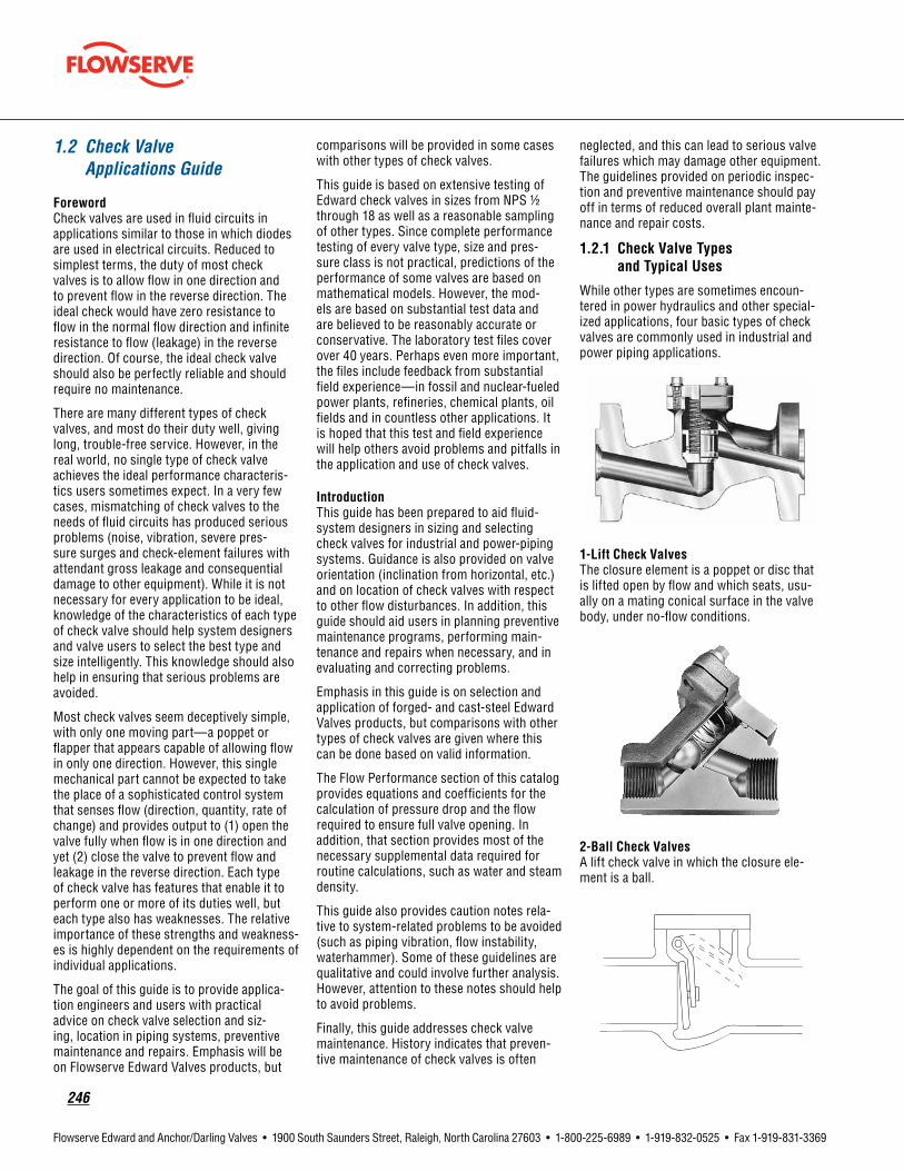
246
Flowserve Edward and Anchor/Darling Valves • 1900 South Saunders Street, Raleigh, North Carolina 27603 • 1-800-225-6989 • 1-919-832-0525 • Fax 1-919-831-3369
1.2 Check Valve Applications Guide
ForewordCheck valves are used in fluid circuits in applications similar to those in which diodes are used in electrical circuits. Reduced to simplest terms, the duty of most check valves is to allow flow in one direction and to prevent flow in the reverse direction. The ideal check would have zero resistance to flow in the normal flow direction and infinite resistance to flow (leakage) in the reverse direction. Of course, the ideal check valve should also be perfectly reliable and should require no maintenance.
There are many different types of check valves, and most do their duty well, giving long, trouble-free service. However, in the real world, no single type of check valve achieves the ideal performance characteris-tics users sometimes expect. In a very few cases, mismatching of check valves to the needs of fluid circuits has produced serious problems (noise, vibration, severe pres-sure surges and check-element failures with attendant gross leakage and consequential damage to other equipment). While it is not necessary for every application to be ideal, knowledge of the characteristics of each type of check valve should help system designers and valve users to select the best type and size intelligently. This knowledge should also help in ensuring that serious problems are avoided.
Most check valves seem deceptively simple, with only one moving part—a poppet or flapper that appears capable of allowing flow in only one direction. However, this single mechanical part cannot be expected to take the place of a sophisticated control system that senses flow (direction, quantity, rate of change) and provides output to (1) open the valve fully when flow is in one direction and yet (2) close the valve to prevent flow and leakage in the reverse direction. Each type of check valve has features that enable it to perform one or more of its duties well, but each type also has weaknesses. The relative importance of these strengths and weakness-es is highly dependent on the requirements of individual applications.
The goal of this guide is to provide applica-tion engineers and users with practical advice on check valve selection and siz-ing, location in piping systems, preventive maintenance and repairs. Emphasis will be on Flowserve Edward Valves products, but
comparisons will be provided in some cases with other types of check valves.
This guide is based on extensive testing of Edward check valves in sizes from NPS 1/2 through 18 as well as a reasonable sampling of other types. Since complete performance testing of every valve type, size and pres-sure class is not practical, predictions of the performance of some valves are based on mathematical models. However, the mod-els are based on substantial test data and are believed to be reasonably accurate or conservative. The laboratory test files cover over 40 years. Perhaps even more important, the files include feedback from substantial field experience—in fossil and nuclear-fueled power plants, refineries, chemical plants, oil fields and in countless other applications. It is hoped that this test and field experience will help others avoid problems and pitfalls in the application and use of check valves.
IntroductionThis guide has been prepared to aid fluid-system designers in sizing and selecting check valves for industrial and power-piping systems. Guidance is also provided on valve orientation (inclination from horizontal, etc.) and on location of check valves with respect to other flow disturbances. In addition, this guide should aid users in planning preventive maintenance programs, performing main-tenance and repairs when necessary, and in evaluating and correcting problems.
Emphasis in this guide is on selection and application of forged- and cast-steel Edward Valves products, but comparisons with other types of check valves are given where this can be done based on valid information.
The Flow Performance section of this catalog provides equations and coefficients for the calculation of pressure drop and the flow required to ensure full valve opening. In addition, that section provides most of the necessary supplemental data required for routine calculations, such as water and steam density.
This guide also provides caution notes rela-tive to system-related problems to be avoided (such as piping vibration, flow instability, waterhammer). Some of these guidelines are qualitative and could involve further analysis. However, attention to these notes should help to avoid problems.
Finally, this guide addresses check valve maintenance. History indicates that preven-tive maintenance of check valves is often
neglected, and this can lead to serious valve failures which may damage other equipment. The guidelines provided on periodic inspec-tion and preventive maintenance should pay off in terms of reduced overall plant mainte-nance and repair costs.
1.2.1 CheckValveTypesandTypicalUses
While other types are sometimes encoun-tered in power hydraulics and other special-ized applications, four basic types of check valves are commonly used in industrial and power piping applications.
1-LiftCheckValvesThe closure element is a poppet or disc that is lifted open by flow and which seats, usu-ally on a mating conical surface in the valve body, under no-flow conditions.
2-BallCheckValvesA lift check valve in which the closure ele-ment is a ball.

flowserve.com
247
Flowserve Edward and Anchor/Darling Valves • 1900 South Saunders Street, Raleigh, North Carolina 27603 • 1-800-225-6989 • 1-919-832-0525 • Fax 1-919-831-3369
3-SwingCheckValvesThe closure element is a pivoted flapper that is swung open by flow and which seats, generally against a mating flat surface in the valve body, under no-flow conditions.
4-Tilting-DiscCheckValveThe closure element is a pivoted disc or flapper, somewhat like that in a swing check valve but with a pivot axis close to the center of the flow stream. It is swung open by flow and seats against a mating conical surface in the valve body under no-flow conditions.
There are many variations among these four basic types of check valves. For example, springs may be included to assist closure and counteract gravitational forces, and accesso-ries may be provided for exercising or posi-tion indication. All Edward lift check valves employ body-guided discs with a piston-like extension to provide good guidance and resistance to wear. Accordingly, they are referred to in this guide as piston-lift check valves. In addition, Flowserve manufactures Edward stop-check valves that are piston-lift check valves that allow positive closure for isolation, just like globe stop valves.
Illustrations of the Edward valve types manufactured by Flowserve are provided in this catalog, and brief notes on advantages, disadvantages, applications, and limitations are provided in the Check Valve Applications Chart (section 1.2.2). Some further highlights of the features of these valves are provided in the following paragraphs.
EdwardPiston-LiftCheckValvesIn both small forged-steel and large cast-steel Edward lines, three distinctly different valve body styles appear in the illustrations – inclined-bonnet globe valve style, angle valve style, and 90° bonnet globe valve style.
With respect to check valve function, these valves are all similar, with only slightly dif-ferent orientation limits as discussed in the Valve-Installation Guidelines section (1.3). The main difference between these systems is in flow performance:
• Inclined-bonnet piston-lift check valves produce low pressure drop due to flow when fully open. They have flow coefficients comparable to those of tilting-disc check valves and only slightly lower than provided by many swing check valves.
• In most cases, angle piston-lift check valves have lower flow coefficients and thus produce more pressure drop than inclined-bonnet valves, but they are superior to 90° bonnet valves. Where a piping system requires a bend and a valve, use of an angle piston-lift check valve eliminates the cost and pressure drop of an elbow and the cost of as-sociated piping welds or flanged connections.
• 90° bonnet piston-lift check valves have the lowest flow coefficients and produce pressure drops comparable to 90° bonnet globe valves. They are sometimes preferred in systems where pressure drop is not critical or where space requirements dictate a mini-mum size and easy access to a handwheel or actuator (on a stop-check valve).
Piston-lift check valves are generally the most practical type for small sizes, and they generally provide the best seat tightness. Small forged-steel piston-lift check valves normally include a disc-return spring, but may be ordered without springs. The Flow Performance section of this catalog and section 1.3 on page 250 address such valves, both with and without springs. Cast-steel piston-lift check valves have equalizer tubes which connect the volume above the piston with a relatively low-pressure region near the valve outlet. This feature allows a much larger valve opening (and higher flow coeffi-cient) than would be possible otherwise, and
it allows the valve to open fully at a relatively low flow.
The body-guided feature of Edward piston-lift check valves is an advantage in most services, because it ensures good alignment of the disc with the valve seat and minimizes lateral vibration and wear. However, this feature may lead to sticking problems due to foreign-material entrapment in unusually dirty systems. Another inherent character-istic is that large piston-lift check valves may not respond rapidly to flow reversals and may cause waterhammer problems in systems where the flow reverses quickly [see the Pressure Surge and Waterhammer section (1.4.2)]. Since smaller valves display inherently faster response, historic files have shown no waterhammer problems with small forged-steel check valves.
EdwardStop-CheckValvesStop-check valves offer the same tight seal-ing performance as a globe stop valve and at the same time give piston-lift check valve protection in the event of backflow. A stop-check valve is nearly identical to a stop valve, but the valve stem is not connected to the disc. When the stem is in the “open” position, the disc is free to open and close in response to flow, just as in a piston-lift check valve. When serving as a check valve, stop-check valves display the same advantages and disadvantages as discussed above for piston-lift check valves. Small forged-steel stop-check valves, except the Univalve stop-check valves, employ a disc-return spring, and cast-steel stop-check valves have equalizer tubes that function in the same manner as those on comparable piston-lift check valves.
The stem in the stop-check valve may be driven either by a handwheel or an actuator, and it may be used either to (1) prevent flow in the normal direction when necessary for isolation or (2) supplement line pressure to
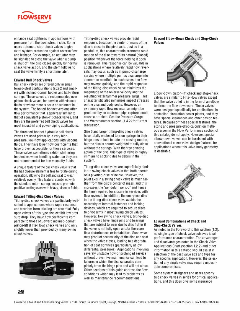
248
Flowserve Edward and Anchor/Darling Valves • 1900 South Saunders Street, Raleigh, North Carolina 27603 • 1-800-225-6989 • 1-919-832-0525 • Fax 1-919-831-3369
enhance seat tightness in applications with pressure from the downstream side. Some users automate stop-check valves to give extra system protection against reverse flow and leakage. For example, an actuator may be signaled to close the valve when a pump is shut off; the disc closes quickly by normal check valve action, and the stem follows to seat the valve firmly a short time later.
EdwardBallCheckValvesBall check valves are offered only in small forged-steel configurations (size 2 and small-er) with inclined-bonnet bodies and ball-return springs. These valves are recommended over piston check valves, for service with viscous fluids or where there is scale or sediment in the system. The bolted-bonnet versions offer flow performance that is generally similar to that of equivalent piston-lift check valves, and they are the preferred ball check valves for most industrial and power-piping applications.
The threaded-bonnet hydraulic ball check valves are used primarily in very high-pressure, low-flow applications with viscous fluids. They have lower flow coefficients that have proven acceptable for those services. These valves sometimes exhibit chattering tendencies when handling water, so they are not recommended for low-viscosity fluids.
A unique feature of the ball check valve is that the ball closure element is free to rotate during operation, allowing the ball and seat to wear relatively evenly. This feature, combined with the standard return spring, helps to promote positive seating even with heavy, viscous fluids.
EdwardTilting-DiscCheckValvesTilting-disc check valves are particularly well-suited to applications where rapid response and freedom from sticking are essential. Fully open valves of this type also exhibit low pres-sure drop. They have flow coefficients com-parable to those of Edward inclined-bonnet piston-lift (Flite-Flow) check valves and only slightly lower than provided by many swing check valves.
Tilting-disc check valves provide rapid response, because the center of mass of the disc is close to the pivot axis. Just as in a pendulum, this characteristic promotes rapid motion of the disc toward its natural (closed) position whenever the force holding it open is removed. This response can be valuable in applications where relatively rapid flow rever-sals may occur, such as in pump-discharge service where multiple pumps discharge into a common manifold. In such cases, the flow may reverse quickly, and the rapid response of the tilting-disc check valve minimizes the magnitude of the reverse velocity and the resulting waterhammer pressure surge. This characteristic also minimizes impact stresses on the disc and body seats. However, an extremely rapid flow reversal, as might be produced by an upstream pipe rupture, could cause a problem. See the Pressure Surge and Waterhammer section (1.4.2) for further discussion.
Size 6 and larger tilting-disc check valves have totally enclosed torsion springs in their hinge pins to help initiate the closing motion, but the disc is counterweighted to fully close without the springs. With the free pivoting action of the disc, this type of valve is highly immune to sticking due to debris in the system.
Tilting-disc check valve are superficially simi-lar to swing check valves in that both operate on a pivoting-disc principle. However, the pivot axis in a swing check valve is much far-ther from the disc’s center of mass, and this increases the “pendulum period” and hence the time required for closure in services with flow reversal. In addition, the one-piece disc in the tilting-disc check valve avoids the necessity of internal fasteners and locking devices, which are required to secure discs to pivot arms in most swing check valves. However, like swing check valves, tilting-disc check valves have hinge pins and bearings that are subject to wear due to disc flutter if the valve is not fully open and/or there are flow disturbances or instabilities. Such wear may product eccentricity of the disc and seat when the valve closes, leading to a degrada-tion of seat tightness (particularly at low differential pressures). Applications involving severely unstable flow or prolonged service without preventive maintenance can lead to failures in which the disc separates com-pletely from the hinge pins and will not close. Other sections of this guide address the flow conditions which may lead to problems as well as maintenance recommendations.
EdwardElbow-DownCheckandStop-CheckValves
Elbow-down piston-lift check and stop-check valves are similar to Flite-Flow valves except that the valve outlet is in the form of an elbow to direct the flow downward. These valves were designed specifically for applications in controlled-circulation power plants, and they have special clearances and other design fea-tures. Because of these special features, the sizing and pressure-drop calculation meth-ods given in the Flow Performance section of this catalog do not apply. However, special elbow-down valves can be furnished with conventional check valve design features for applications where this valve-body geometry is desirable.
EdwardCombinationsofCheckand Stop-CheckValvesAs noted in the Foreword to this section (1.2), no single type of check valve achieves ideal performance characteristics. The advantages and disadvantages noted in the Check Valve Applications Chart (section 1.2.2) and other information in this catalog should assist in selection of the best valve size and type for any specific application. However, the selec-tion of any single valve may require undesir-able compromises.
Some system designers and users specify two check valves in series for critical applica-tions, and this does give some insurance

flowserve.com
249
Flowserve Edward and Anchor/Darling Valves • 1900 South Saunders Street, Raleigh, North Carolina 27603 • 1-800-225-6989 • 1-919-832-0525 • Fax 1-919-831-3369
1.2.2 CheckValveApplicationsChart
Type Advantages Disadvantages Applications Limitations
PistonLiftCheck
• Very low pressure drop in inclined bonnet valves
• Relatively low pressure drop in angle valves
• Larger valves incorporate an external equalizer
• Minimum chatter due to flow disturbances
• Good seat tightness
• Forged steel valves with spring can be mounted in any orientation
• Relatively high pressure drop in 90° bonnet valves
• Subject to “sticking” in very dirty systems
• Class 300-4500 service
• High temperature steam and water
• Refining, petrochmical, chemical, etc.
• Oilfield production
• Can be used in series with Tilting-Disc Check to provide maximum line protection (advantages of both types)
• Sizes 1/4" through 24"
• For orientation limits, see valve installation guidelines
• For flow limits, see Flow Performance section of this catalog
BallCheck
• Wear on body seat and check element evenly distributed
• Long service life
• Forged steel valves with spring can be mounted in any orientation
• Available with either integral or threaded seat for hydraulic valve
• Low cost
• High pressure drop
• Available only in small sizes
• Class 600 and Series 1500 service
• Water, steam, refining, petrochemical, chemical, etc.
• Service where scale and sediment exist
• Viscous fluids
• Sizes 1/4" through 2"
• For orientation limits see valve installation guidelines
• Not recommended for gas service at low flow rates
• For flow limits, see Flow Performance section of this catalog
Tilting-DiscCheck
• Very low pressure drop
• Straight through body design
• Very fast closing
• Minimizes disc slamming and waterhammer pressure surges
• Will not “stick” in dirty systems
• Not recommended for service with rapidly fluctu-ating flow
• Seat tightness may dete-riorate at low differential pressure
• Class 600-4500 service
• High temperature steam and water
• Refining, petrochemical, chemical, etc.
• Oilfield production
• Can be used in series with Piston Lift check or Stop-Check to provide maximum line protection (advantages of both types)
• Sizes 21/2" through 24"
• For orientation limits, see valve installation guidelines
• For flow limits, see Flow Performance section of this catalog
StopCheck
• See Piston Lift Check above
• Can be used for Stop valve service
• Stem can be lowered onto disc to prevent chatter at low flow
• Stem force can overcome “sticking”
• See Piston Lift Check valve above
• See Piston Lift Check above • See Piston Lift Check above
SwingCheck
• Best general service check valve
• Tight sealing
• Lowest pressure drop
• Not good for low or pulsating flows
• Slower response to reverse flow
• Susceptible to causing waterhammer
• Class 150-2500 service
• High temperature steam and water including containment isolation
• Sizes 21/2" through 24"

250
Flowserve Edward and Anchor/Darling Valves • 1900 South Saunders Street, Raleigh, North Carolina 27603 • 1-800-225-6989 • 1-919-832-0525 • Fax 1-919-831-3369
that at least one valve will close even if the other valve fails. However, if two identical valves are used, a system characteristic that is troublesome to one valve could produce problems with both. In such cases, use of two valves does not ensure double safety or double life. Sometimes it is worth consider-ing the selection of two different types of check valve, each with advantages to offset disadvantages of the other.
One specific check valve combination has been used in applications of Flowserve Edward valves to provide advantages that no single valve can offer. A tilting-disc check valve in series with a piston-lift check valve offers minimum waterhammer and freedom from sticking (from the tilting disc) and good seat tightness (from the piston-lift check). The disadvantage is added pressure drop and cost, but the pressure-drop penalty is minor if the Flite-Flow inclined-bonnet piston-lift check valve is used. Even the cost penalty may be offset if a stop-check valve is used, because it may be able to take the place of a stop valve that would be required otherwise for isolation.
1.3 Check and Stop-Check Valve Installation Guidelines
Unlike stop valves, which can be installed in any position with little or no effect on perfor-mance, most check and stop-check valves have limitations as to their installed orienta-tion. Although the normal installation is in a horizontal or vertical line (depending on valve type), check and stop-check valves can be installed in other orientations. It should be noted, however, that valves installed in other than the normal positions may exhibit a degradation of performance, service life and resistance to sticking, depending on the flow conditions and cleanliness of the line fluid. For maximum reliability, it is recommended that piston-lift check valves and stop-check valves be installed with flow axis horizontal (vertical inlet and horizontal outlet for angle valves) with the bonnet above the valve in a vertical plane. Following are maximum out-of-position orientations that may be used for less critical applications and which should never be exceeded.
• All Edward forged-steel check and stop-check valves (except Univalve stop-check valves) are normally furnished with spring-loaded discs and may be installed in any position. The spring-loaded disc enables positive closure regardless of valve position.
However, installed positions in which dirt or scale can accumulate in the valve neck should be avoided. An example of this would be an inclined-bonnet valve installed in a ver-tical pipeline with downward flow. If forged-steel valves are ordered without springs, the limitations below should be observed.
• Edward cast-steel Flite-Flow, forged-steel Univalve, and inclined-bonnet check and stop-check valves without springs, when installed in vertical or near vertical lines,
should be oriented such that the fluid flow is upward and the angle of incline of the line is not more than 5° past the vertical in the direction of the bonnet. When installed in horizontal or near horizontal lines, the valve bonnet should be up and the angle of incline of the line should be not more than 5° below the horizontal. See Figure 1A. Also, the roll angle of the valve bonnet should not be more than 20° from side to side for either vertical or horizontal installations. See Figures
Figure 290°BonnetPistonLiftCheckValvesMaximumValveOrientationLimits
Figure 1 45°InclinedBonnetPistonLiftCheckValvesMaximumCheckValveOrientationLimits
Note: For piston lift check valves, any installation resulting in combined out-of-position orientation, such as a valve in an inclined line with a rollover angle as well, should limit the angle of the bonnet to the following:
• 45° from vertical for angle and 90° bonnet valves.
• 50° from vertical for inclined bonnet valves.

flowserve.com
251
Flowserve Edward and Anchor/Darling Valves • 1900 South Saunders Street, Raleigh, North Carolina 27603 • 1-800-225-6989 • 1-919-832-0525 • Fax 1-919-831-3369
1B and 1C. Consult your Flowserve Edward Valves representative concerning installation limits of bolted-bonnet forged-steel check valves without springs.
• Edward cast-steel and forge-steel 90° bonnet check and stop-check valves without springs should be installed with the bonnet up, and the angle of incline of the line should not be more than 45° from the horizontal. Also, the roll angle of the valve bonnet should not be more than 45° from side to side. See Figures 2A and 2B.
• Edward cast-steel and forged-steel angle check and stop-check valves without springs should be oriented such that the incoming flow is upward, and the angle of incline of the line should not be more than 45° in either direction. See Figures 3A and 3B.
• Edward tilting-disc check valves may be installed in horizontal lines and vertical lines and at any incline angle in between. When the incline angle is not horizontal, flow should al-ways be up. The roll angle of the valve should not be more than 30° from side to side. See Figures 4A and 4B. Also, when installed in other than vertical lines, the bonnet should always be oriented up.
In each case described above, the limitations given for line inclination and bonnet roll angle should not be combined.
It should be understood that the information given in the section of this catalog titled Flow Performance is based on traditional horizon-tal orientations. For other orientations, the pressure drop and flow required for full lift may be affected. In addition, seat tightness, particularly at low differential pressures, may be adversely affected.
Orientation restrictions may also exist for power-actuated stop-check valves. Most linear valve actuators are designed to be mounted upright and nearly vertical, although they can usually be modified for mounting in any posi-tion. When selecting a stop-check valve and power actuator, be sure to specify the mount-ing position desired if not vertical and upright.
Figure 3AnglePistonLiftCheckValvesOrientation Limits
Figure 4Tilting-DiscCheckValves Orientation Limits
Figure 5 Pipefittingsnearvalvesmayproduceinstabilitybecauseofvelocityprofiledistortion
Figure 7Elbowsintwoplacescauseswirl,whichcanpromoteinstability.
Figure 6Non-uniformvelocityprofileatblowerorpumpdischargecanaffectstability.

252
Flowserve Edward and Anchor/Darling Valves • 1900 South Saunders Street, Raleigh, North Carolina 27603 • 1-800-225-6989 • 1-919-832-0525 • Fax 1-919-831-3369
1.3.1 AdjacentFlowDisturbances
Check valves, like other valve types, are gener-ally tested for performance and flow capacity in long, straight-pipe runs. Flow coefficients obtained from these tests are then used to predict the flow rate or pressure drop that will be experienced in actual applications. The ideal installation of a check valve in a plant would be in a long run of straight pipe so that performance would correspond to the test conditions. Since space limitations involved with many installations preclude such ideal straight-pipe runs, the effects of adjacent pipe fittings, control valves, pumps and other flow disturbances must be considered.
Previously published data have indicated that flow disturbances, particularly up-stream disturbances, may significantly affect check valve performance. It has been reported that valve flow capacity may be significantly reduced as compared to that measured in straight-pipe tests, and there have been strong suggestions that such disturbances aggravate check valve flutter and vibration. Since these conditions could degrade valve performance and contribute to rapid wear and premature valve failure, they are important factors in evaluating check valve applications. Figure 5 illustrates how upstream pipe fittings may alter the flow profile entering a check valve, crowding it to one side or the other. A similar distortion occurs in a valve located near the discharge of a centrifugal pump or blower, as shown in Figure 6. Elbows in two planes cause a flow stream to swirl, which might produce unusual effects on a check valve installed as shown in Figure 7.
Since there was no known way to predict the effects of flow disturbances on check valves by mathematical models, Flowserve con-ducted extensive testing of size 2, 4, 8 and 10 check valves in straight-pipe runs and in pip-ing with upstream flow disturbances. Figures 8 and 9 illustrate typical flow-test setups.
Figure 8Size 4 Class 600 90° bonnet piston lift check valve with two upstream elbows (out of plane). This arrangement produces swirl as shown in Figure 7.
Figure 9Size 10 Class 1500 Flite-Flow inclined bonnet piston lift check valve with two upstream elbows. Test loop capacity permitted tests with line velocity over 20 ft/s (6 m/s).
In most tests, room-temperature water was the flow medium, but limited straight-pipe testing was performed with air. The valves tested included Edward piston-lift check (inclined-bonnet, angle and 90° bonnet), tilting-disc check valves and a size 4 swing check valve manufactured by another com-pany. The tests were designed to evaluate the effects of flow disturbances on (1) valve stability, particularly when partially open; (2) flow rate required to open the valve fully; and (3) the flow coefficient (CV) of the valve. The flow disturbances evaluated included single and double (out of plane) 90° elbows in vari-ous orientations immediately upstream of the check valves. In addition, the effects of a throttled, upstream control valve were simu-lated with an offset-disc butterfly valve (at various throttle positions) mounted immedi-
ately upstream, as well as at five and 11 pipe diameters upstream, of the check valves.
With few exceptions, tests with 10 or more diameters of straight pipe upstream of check valves produced little cause for concern. In water flow tests, visual position indicators usually showed only minor disc “wobble” or very small open-close flutter (e.g., less than 1° total rotation of a tilting disc), even at very low flows and small valve openings. The only conditions that produced severe instabil-ity were those involving air flow at very low pressures (below 50 psi or 3.4 bar) and valve openings less than 20%. Such conditions produced significant cyclic motion, with discs bouncing on and off the body seats. In view or the many uncertainties in applying laboratory test results to service conditions, it is considered prudent to avoid operating conditions which produce check valve open-ings of less than 25%, even in ideal straight-pipe applications.
Highlights of the results of the Flowserve tests with flow disturbances are given in the Check Valve Applications Chart (1.2.2) on page 249. The test program clearly showed that upstream flow disturbances do affect check valve performance, but the effect is not always predictable. The magnitude of the effect can vary, depending on the type and even the size of the valve. In some cases, even the direction of the effect (improvement or degradation) varies from valve to valve. Nevertheless, some general observations on the results of these tests are:
• Single and double upstream elbows produced less severe effects on check valve performance than had been expected, and some valves displayed no discernible effects. For example, Edward angle piston-lift check valves exhibited the same stability, lift and flow coefficients (CV) with upstream elbows as with straight pipe. In tests of other types of valves, upstream elbows produced both beneficial and adverse effect to various degrees.
• In each case where a check valve was tested with a throttled butterfly valve immediately upstream, there were significant effects on performance. The effects included increased disc flutter and reduced valve opening at a given flow, as compared to straight-pipe performance. In some cases, full check valve opening could not be achieved at any flow within the capabilities of the test loop.
Even where full opening was obtained, some valves continued to flutter on and off their
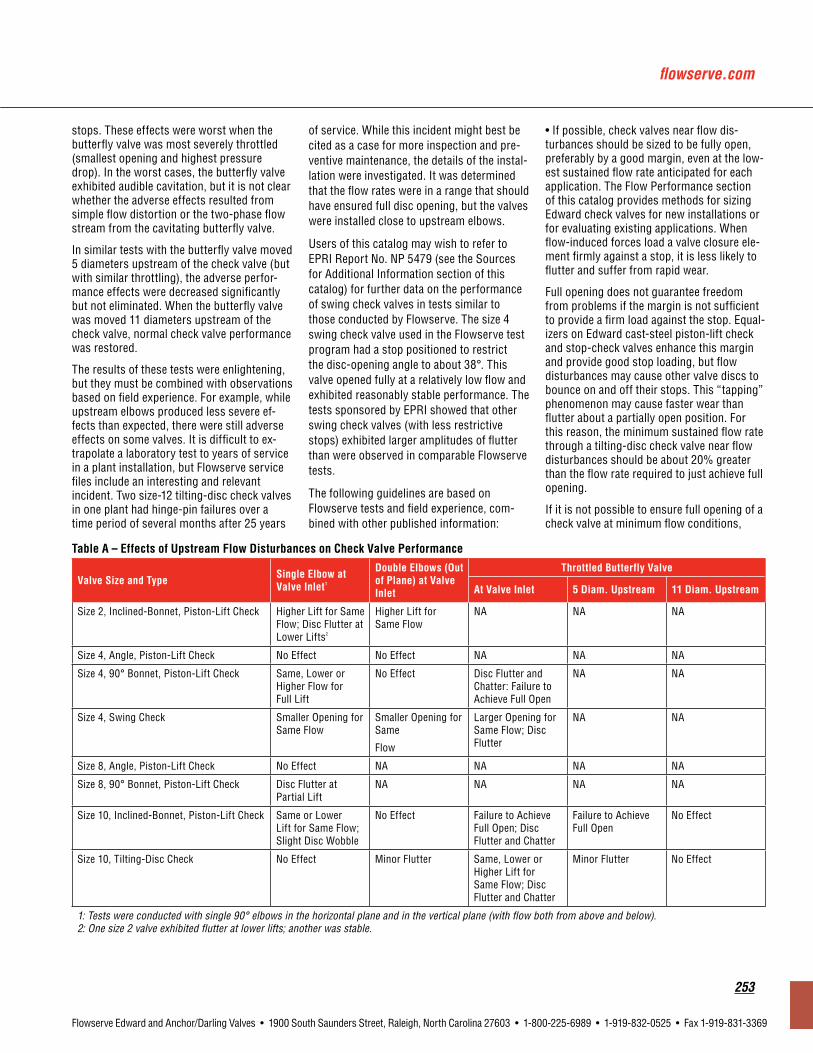
flowserve.com
253
Flowserve Edward and Anchor/Darling Valves • 1900 South Saunders Street, Raleigh, North Carolina 27603 • 1-800-225-6989 • 1-919-832-0525 • Fax 1-919-831-3369
stops. These effects were worst when the butterfly valve was most severely throttled (smallest opening and highest pressure drop). In the worst cases, the butterfly valve exhibited audible cavitation, but it is not clear whether the adverse effects resulted from simple flow distortion or the two-phase flow stream from the cavitating butterfly valve.
In similar tests with the butterfly valve moved 5 diameters upstream of the check valve (but with similar throttling), the adverse perfor-mance effects were decreased significantly but not eliminated. When the butterfly valve was moved 11 diameters upstream of the check valve, normal check valve performance was restored.
The results of these tests were enlightening, but they must be combined with observations based on field experience. For example, while upstream elbows produced less severe ef-fects than expected, there were still adverse effects on some valves. It is difficult to ex-trapolate a laboratory test to years of service in a plant installation, but Flowserve service files include an interesting and relevant incident. Two size-12 tilting-disc check valves in one plant had hinge-pin failures over a time period of several months after 25 years
of service. While this incident might best be cited as a case for more inspection and pre-ventive maintenance, the details of the instal-lation were investigated. It was determined that the flow rates were in a range that should have ensured full disc opening, but the valves were installed close to upstream elbows.
Users of this catalog may wish to refer to EPRI Report No. NP 5479 (see the Sources for Additional Information section of this catalog) for further data on the performance of swing check valves in tests similar to those conducted by Flowserve. The size 4 swing check valve used in the Flowserve test program had a stop positioned to restrict the disc-opening angle to about 38°. This valve opened fully at a relatively low flow and exhibited reasonably stable performance. The tests sponsored by EPRI showed that other swing check valves (with less restrictive stops) exhibited larger amplitudes of flutter than were observed in comparable Flowserve tests.
The following guidelines are based on Flowserve tests and field experience, com-bined with other published information:
• If possible, check valves near flow dis-turbances should be sized to be fully open, preferably by a good margin, even at the low-est sustained flow rate anticipated for each application. The Flow Performance section of this catalog provides methods for sizing Edward check valves for new installations or for evaluating existing applications. When flow-induced forces load a valve closure ele-ment firmly against a stop, it is less likely to flutter and suffer from rapid wear.
Full opening does not guarantee freedom from problems if the margin is not sufficient to provide a firm load against the stop. Equal-izers on Edward cast-steel piston-lift check and stop-check valves enhance this margin and provide good stop loading, but flow disturbances may cause other valve discs to bounce on and off their stops. This “tapping” phenomenon may cause faster wear than flutter about a partially open position. For this reason, the minimum sustained flow rate through a tilting-disc check valve near flow disturbances should be about 20% greater than the flow rate required to just achieve full opening.
If it is not possible to ensure full opening of a check valve at minimum flow conditions,
TableA–EffectsofUpstreamFlowDisturbancesonCheckValvePerformance
ValveSizeandType SingleElbowatValveInlet1
DoubleElbows(OutofPlane)atValveInlet
ThrottledButterflyValve
AtValveInlet 5 Diam. Upstream 11 Diam. Upstream
Size 2, Inclined-Bonnet, Piston-Lift Check Higher Lift for Same Flow; Disc Flutter at Lower Lifts2
Higher Lift for Same Flow
NA NA NA
Size 4, Angle, Piston-Lift Check No Effect No Effect NA NA NA
Size 4, 90° Bonnet, Piston-Lift Check Same, Lower or Higher Flow for Full Lift
No Effect Disc Flutter and Chatter: Failure to Achieve Full Open
NA NA
Size 4, Swing Check Smaller Opening for Same Flow
Smaller Opening for Same
Flow
Larger Opening for Same Flow; Disc Flutter
NA NA
Size 8, Angle, Piston-Lift Check No Effect NA NA NA NA
Size 8, 90° Bonnet, Piston-Lift Check Disc Flutter at Partial Lift
NA NA NA NA
Size 10, Inclined-Bonnet, Piston-Lift Check Same or Lower Lift for Same Flow; Slight Disc Wobble
No Effect Failure to Achieve Full Open; Disc Flutter and Chatter
Failure to Achieve Full Open
No Effect
Size 10, Tilting-Disc Check No Effect Minor Flutter Same, Lower or Higher Lift for Same Flow; Disc Flutter and Chatter
Minor Flutter No Effect
1: Tests were conducted with single 90° elbows in the horizontal plane and in the vertical plane (with flow both from above and below).2: One size 2 valve exhibited flutter at lower lifts; another was stable.

254
Flowserve Edward and Anchor/Darling Valves • 1900 South Saunders Street, Raleigh, North Carolina 27603 • 1-800-225-6989 • 1-919-832-0525 • Fax 1-919-831-3369
at least 25% opening should be ensured. Valves operating at partial opening for sig-nificant periods of time should be monitored regularly to determine if there is instability or wear.
• In view of uncertainties associated with long-term effects of flow disturbances, it is recommended that a minimum of 10 diame-ters of straight pipe be provided between the inlet of a check valve and any upstream flow disturbance (fittings, pumps, control valves, etc.), particularly if calculations indicate that the check valve will not be fully open for a substantial portion of the valve service life. There should be a minimum of 1 to 2 diame- ters of pipe between the check valve and the nearest downstream flow disturbance.
• In the specific case of upstream elbows, reasonably successful performance should be attainable with 5 diameters of straight pipe between an upstream elbow and a check valve if the valve will not be partially open for a significant portion of its service life. Tests described in EPRI Report No. NP 5479 indicate that elbows installed 5 diameters or more upstream had a negligible effect on swing check valves, and this is expected to be true for other check valve types. Even less straight pipe may be satisfactory, but such close spacing should be reserved for applica-tions with very tight space constraints. More frequent inspection and preventive mainte-nance should be planned for valves in such installations.
• In the specific case of throttled upstream control valves, the minimum requirement of 10 upstream pipe diameters should be adhered to rigidly. Calculations indicating full valve opening based on straight-pipe tests cannot be trusted to prevent problems, be-cause severe flow disturbances may prevent full opening. Even greater lengths of straight pipe should be considered if the control valve operates with very high pressure drop or significant cavitation.
• Users with existing check valve installations that do not meet these guidelines should plan more frequent inspection and preventive maintenance for such valves. If a check valve is installed close to an upstream control valve that operates with a high-pressure drop, considerations should be given to a change in piping or valve arrangements.
1.3.2 OtherProblemSources
In addition to the fundamentals of check valve selection, sizing and installation, several other potential sources of check valve
problems should be considered in applica-tions engineering or, if necessary, in solving problems with existing installations:
•Piping-SystemVibrationIn other sections of this guide, it has been noted that check valve damage or perfor-mance problems may result from flow-induced flutter or vibration of the closure ele-ment. Very similar damage may result from piping-system vibration. Such vibration may originate at pumps, cavitating control valves or other equipment. Check and stop-check valves are susceptible to vibration damage, because the check element is “free floating” when partially open, with only the forces due to fluid flow to balance the moving weight. Impact damage and internal wear may result if the valve body vibrates while internal parts attempt to remain stationary. This condition may be avoided by adequately supporting the piping system near the check valve or by damping vibration at its source. Of course, it is helpful to ensure that the check element opens fully, because flow forces at the disc-stop help to inhibit relative motion.
•DebrisinLineFluidDebris in the flow stream can cause dam-age and performance problems in check and stop-check valves. Debris entrapped between the disc and seat may prevent full closure and lead directly to seat leakage. If hard particles or chips are in the debris, they may damage the seating surfaces and contribute to seat leakage even after they are flushed away. Debris caught between the disc and the body bore of a piston-lift check valve can cause the disc to jam and prevent full opening or clos-ing. To ensure best check valve performance and seat tightness, line fluids should be kept as clean as practical. As noted before, tilting-disc check valves are particularly resistant to sticking or jamming, but they are no more resistant to seat damage than other types.
•Unsteady(Pulsating)FlowAn unsteady flow rate can lead to rapid check valve damage, particularly if the minimum flow during a cycle is not sufficient to hold the valve fully open. The valve may be damaged just because it does what a check valve is designed to do – open and close in response to changes in flow. As an example, a check valve installed too close to the outlet of a positive displacement pump may attempt to respond to the discharge of each cylinder. If the mean flow during a cycle is low, the disc may bounce off the seat repeatedly in a chattering action. If the mean flow is higher,
the disc may bounce on and off the full-open stop. Such pulsating flows may be difficult to predict. For example, a steam leak past the seat of an upstream stop valve may produce a “percolating” action in a line filled with condensate and cause a check valve to cycle. Such problems may only be discovered by preventive maintenance inspections.
•VaporPocketsinLiquidPipingSystemsUnusual phenomena are sometimes observed in piping systems containing hot water that partially vaporizes downstream of a closed check valve. Vapor pockets at high points may collapse suddenly when the check valve opens (due to the start-up of a pump, for example). This collapse may be remote from the check valve and have no effect on the check valve performance. However, if a vapor pocket exists in the upper part of a piston-lift check or stop-check valve body (above the disc), the collapse may generate unbalanced forces in the direction of disc opening. Since the vapor offers little fluid resistance, rapid acceleration of the disc toward the fully open position may occur. In extreme cases, the disc or bonnet stops may be damaged due to impact. Such thermodynamic quirks are difficult to anticipate when designing a piping system and are sometimes as difficult to diagnose if they occur in an existing instal-lation. Changes in piping arrangements or operating procedures may be necessary if severe problems occur. It is possible that similar problems may occur during low-pressure start-up operations in unvented liquid-piping systems.
1.4 Check Valve Performance1.4.1 CheckValveSeatTightness
Edward check valves are factory-tested with water in accordance with MSS SP-61 (Manufacturers Standardization Society of the Valve and Fittings Industry, Inc.) at an overseat pressure of 1.1 times the pressure ratings of the valve. While check valves are allowed leakage rates up to 40 ml/hr per unit of nominal valve size by MSS SP-61, Flowserve allows no more than 5% of this leakage for cast-steel valves and no visible leakage for forged-steel valves. Tilting-disc and forged-steel check valves are then tested again at a reduced pressure with allowable leakage rates which are less than the MSS SP-61 requirements.
Closed check valve closure elements (disc, ball, flapper, etc.) are acted on by a combina-tion of forces produced by gravity, springs

flowserve.com
255
Flowserve Edward and Anchor/Darling Valves • 1900 South Saunders Street, Raleigh, North Carolina 27603 • 1-800-225-6989 • 1-919-832-0525 • Fax 1-919-831-3369
(where applicable) and reversed differential pressure. While gravity and spring forces help to position the closure element into the substantially closed position, metal-to-metal seating check valves typically rely on pressure forces to produce the seating loads necessary for good seat tightness.
Some metal-seated check valves do not produce good seat tightness at low differen-tial pressures, particularly when the pressure increases from zero. A threshold level of differential pressure is required to produce uniform metal-to-metal contact and restrict leakage to a reasonable rate. An even higher level is required to ensure that a valve meets leakage-rate criteria like those in MSS SP-61. Unfortunately, these levels of differential pressure are difficult to predict; they vary with valve type, condition and orientation (and with cleanliness of line fluid).
Tests of new valves in horizontal lines show that cast-steel inclined-bonnet and 90° bon-net piston-lift check and tilting-disc check valves seal off reasonably well at under 50 psi (3.4 bar) when differential pressure increases from zero. Small forged-steel ball and piston-lift check valves are less consis-tent, sometimes seating at less than 50 psi (3.4 bar) and sometimes requiring 250 psi (17 bar) or more. This “seating” action often occurs suddenly when the pressure forces shift the closure element into good metal-to-metal contact with the body seat, and leakage generally continues to decrease as the pressure is increased. Once seated, most valves seal well if pressure is reduced below the threshold required for initial seating, but the seat tightness with reducing pressure is also difficult to predict.
Some of the Edward check valves described in this catalog have been manufactured with “soft seats” to provide improved seat tightness at low differential pressures. This design feature includes an elastomeric or plastic sealing member on the valve closure element to supplement the basic metal-to-metal seating function. Since the design and material selection for these sealing members are very sensitive to pressure, temperature and compatibility with the line fluid, there are no standard, general-purpose, soft-seated valves. Consult Flowserve for further infor-mation about specific applications.
Foreign material in the flow medium is a major source of leakage problems in many valves. Because of the limited seating forces in check valves, dirt has a far greater effect on the tightness of these valves than other
types. Attention to cleanliness of the fluid is necessary where good check valve seat tight-ness is desired.
Incorrect sizing or misapplication of a check valve can also lead to leakage problems. Chattering of the closure element on its seat due to insufficient flow or pressure can cause damage to the seat or closure element and result in leakage.
In applications where check valve leakage is a problem, a stop-check valve may offer the solution. Stem load from a handwheel or actuator can provide the necessary seating force independent of pressure. Of course, the stem must be returned to the “open” position to allow flow in the normal direction. Consult Flowserve about applications that are usually sensitive to leakage.
A complete treatment of the subject of pres-sure surge and waterhammer is beyond the scope of this catalog, but some discussion is provided so that application engineers may appreciate the significance of the problem as it relates to check valves.
1.4.2 PressureSurge andWaterhammer
One part of the problem is that the terminol-ogy or jargon is not consistently used. For example, “waterhammer” or “steam hammer” is sometimes used to describe the implo-sion that occurs when water enters a hot, low-pressure region and causes a steam void to collapse. This has occurred in systems with a failed check valve, where the water came back from a large reverse flow through the check valve. However, the more common “waterhammer” problem associated with check valves occurs as a result of the check valve closing and suddenly terminating a sig-nificant reversed flow velocity. This problem is generally associated with valves handling water or other liquids. A similar pressure-surge phenomenon may be encountered with steam or gas, but it is generally much less serious with a compressible flow medium.
Waterhammer is a pressure surge produced by the deceleration of a liquid column, and it involves pressure waves that travel at close to the velocity of sound through the fluid. It is commonly illustrated in texts by an example involving rapid closure or a valve in a long pipe. For such a case, it can be shown that instantaneous closure of a valve in a room-temperature water line will produce an increase in pressure of about 50 psi (3.4 bar) above the steady-state pressure for every 1
ft/sec (0.30 m/sec) decrease in water veloc-ity. Even if the valve does not close instanta-neously, the same pressure increase would develop if the upstream pipe is long enough to prevent reflected pressure waves from reaching the valve before it closes. The waves of increasing pressure that are generated by the closing valve “reflect” from a constant-pressure reservoir or vessel, if present in the system, and return to the valve as inverted waves that decrease pressure. A solution to the “textbook problem” is to slow down the valve closure so that the reflected pressure waves attenuate the surge. However, this is not necessarily the best approach in the case of a check valve.
In a check valve, the fluid velocity is forward before the valve starts to close, but it reduces due to some system action (e.g., a pump is shut off). If the velocity reverses before the valve closes, a waterhammer surge will be produced by a conventional check valve that is nearly proportional to the magnitude of the maximum reversed velocity. Figure 10 provides curves illustrating flow transients associated with different types of systems and flow interruptions. The graphs illustrate velocity in the pipe, forward and reverse, versus time on arbitrary scales. The following discussions describe each of the curves:
• Curve A illustrates flow coast-down in a simple circulating loop, such as a cooling system, following switch-off of pump power. The momentum of the pump impeller and the fluid keeps the fluid going forward until it is decelerated and finally stopped by friction. There would be no need for a check valve to prevent reverse flow in this system, but one might be included to permit pump mainte-nance without draining other equipment. In normal operation of this system, the check valve could produce no waterhammer.
• Curve B illustrates an application with a pump feeding a high-pressure system with a fairly large volume. It might represent a boiler feed system of a pump feeding a high reservoir. In this case, assuming similar momentum in the pump and fluid, forward flow continues for a while after the pump is switched off, but the downstream pressure decelerates the flow more rapidly and then reverses its direction. Without a check valve, the reverse flow would increase and stabilize at some value, unless the downstream sys-tem pressure declined. In the illustration, the magnitude of the maximum reverse velocity is drawn less than the initial forward velocity, but it might be higher in some systems.

256
Flowserve Edward and Anchor/Darling Valves • 1900 South Saunders Street, Raleigh, North Carolina 27603 • 1-800-225-6989 • 1-919-832-0525 • Fax 1-919-831-3369
• Curve C illustrates what would happen in the system described for Curve B with a fast-response check valve (e.g., a tilting-disc type) installed. As discussed in the Foreword to this guide, an “ideal” check valve would allow no reverse flow and would close exactly at the time the velocity curve passes through zero; there would be no waterhammer. A “real” check valve starts closing while the flow is still forward, but it lags the velocity curve. With fast response, it closes before a high reverse velocity develops, thus minimiz-ing the waterhammer surge.
• Curve D illustrates the same system with a check valve that responds just a bit slower. It shows that just a small increase in check valve lag may allow a large increase in re-
verse velocity (and a corresponding increase in waterhammer surge pressure).
• CurveEillustrates an accidental situation that might develop with a severely worn valve or a dirty system. If a check valve in the system described above should stick open, it might allow the reverse velocity to build up so as to approach that which would occur without a check valve. If the reverse flow forces should then overcome the forces that caused the sticking, the resulting valve stem could cause a damaging waterhammer surge.
• Curve F illustrates what might happen in the system described for Curve B if there were a major pipe rupture just upstream of the check valve. With free discharge through the open end, the flow would decelerate much more rapidly and, without a check valve, reach a much higher reverse velocity.
• CurveGshows the response of the system in Curve F if even a fast-response conven-tional check valve were to be used. With a flow deceleration this rapid, even a small lag may result in a very high reverse velocity to be arrested and a correspondingly high waterhammer surge.
Fortunately, it is not necessary to design every piping system with a check valve to cope with a pipe rupture. However, this requirement has emerged in some power-plant feedwater piping systems. Flowserve
analyses and tests have shown that even the most rapid-responding conventional check valve could produce unacceptable waterham-mer surges. This led to the development of the special controlled-closure check valve (CCCV–see Figure 11). Since high reverse velocities are inevitable, the CCCV solves the problem the way the “textbook problem” dis-cussed above is solved—by closing slowly. The CCCV is a piston-lift check valve, but it has an internal dashpot that slows the closing speed of the valve. Closing speed depends on the rate at which water is squeezed out of the dashpot chamber, through flow paths that are sized for each application.
• CurveHillustrates the velocity variation in the pipe-rupture situation described for Curve F, but with a CCCV in the line. In this case, the maximum reverse velocity might even be higher than in Curve G, but it is decelerated back to zero slowly, allowing reflected reduc-ing-pressure waves to minimize the resulting waterhammer surge. Figure 12 provides a comparison between a conventional check valve and a CCCV for a specific pipe-rupture situation. Note that the conventional check valve closes in 0.07 seconds as compared to 1.0 seconds for CCCV. As a result, the conventional check valve produced a surge of 3000 psi (207 bar) while the CCCV limits the surge to 600 psi (41 bar). These characteris-tics have been demonstrated in tests and can be duplicated in computer-based dynamic analysis simulations of specific valves and systems.
While the CCCV solves a special problem, even this sophisticated product does not fulfill the definition of an ideal check valve. By closing slowly, it allows significant reverse blow before it seats. This character-istic might be undesirable in common pump-discharge applications, because the reverse flow might have adverse effects on pumps or other equipment. Studies of systems designs sometimes show that fast-response check valves, such as the tilting-disc type, should be retained at pump discharge points where an upstream pipe rupture is unlikely, with CCCVs applied at locations where an upstream pipe rupture could cause serious consequences (e.g., in feedwater lines inside the containment vessel of a nuclear power plant).
In Curves C, D, E, and G of Figure 10, it may be noted that the final terminations of reverse velocity are shown as substantially verti-cal lines. This does not imply that the valve closes instantaneously. However, tests of
Figure10-FlowReversalTransients
Description of CurvesA - Pump Trip in Circulating Loop with or without Check ValveB - Pump Trip in Boiler Feed Line - No Check ValveC - Same as B but with Fast Response Check ValveD - Same as B but with Slow Response Check ValveE - Same as C or D but Check Valve Sticks then Unsticks and Slams ClosedF - Upstream Feed Line Rupture - No Check ValveG - Same as F but with Fast Response Check ValveH - Same as F but with Controlled Closure Check Valve
Note: In liquid flow lines, sudden velocity changes as at C, D, E and G produce pressure surges proportional to velocity change.
Figure11-ControlledClosure CheckValve(CCCV)
Dashpot chamber
Normal flow direc-tion

flowserve.com
257
Flowserve Edward and Anchor/Darling Valves • 1900 South Saunders Street, Raleigh, North Carolina 27603 • 1-800-225-6989 • 1-919-832-0525 • Fax 1-919-831-3369
conventional check valves show that the re-verse velocity in the pipe containing the valve does terminate almost instantaneously. This apparent contradiction may be understood by referring to Figure 13, which illustrates a check valve approaching the closed position with reverse flow (while the illustration de-picts a swing check valve, the flow condition discussed here would be much the same with a poppet or disc in a conventional lift check or piston-lift check valve).
The key observation from Figure 13 is that a column of fluid follows the closure element at roughly the same velocity that the closure element has as it approaches its seating
surface in the valve body. While the valve may start to close while the flow velocity is still forward (see Figure 10), an undamped check valve has little effect on pipe flow dur-ing closure, and the disc velocity is about the same as the reverse flow velocity in the pipe at the instant just before closure. Since the disc is stopped substantially instantaneously when it makes metal-to-metal contact with the body seat, the reverse flow velocity in the pipe must also be arrested instantaneously. Because of this characteristic, the surge produced by the slam of a conventional check valve cannot be attenuated significantly by reflected reducing-pressure waves, and the
surge tends to be relatively insensitive to sys-tem pipe lengths.
In some check valve applications, problems have been observed due to a phenomenon that is related to waterhammer but not as widely recognized. When a high-pressure wave is produced on the downstream side of a check valve at closure, a reverse low-pres-sure wave is produced on the upstream side. If this low-pressure wave reduces the fluid pressure to below the saturation pressure of the fluid, a vapor pocket can form. This can be compared to a tensile failure of the flow stream, and it is sometimes referred to as column separation or column rupture. This vapor pocket is unstable and will collapse quickly, with an implosion that produces a high-pressure “spike.” It is possible for this pressure surge to exceed the one initially pro-duced on the downstream of the check valve. Instrumented laboratory tests have shown that the upstream pressure spike some-times causes the disc to reopen slightly and “bounce” off its seat once or twice. In very rare occasions, sometimes involving systems with multiple check valves, this character-istic has been known to amplify, leading to damaging pipe vibrations.
In summary, waterhammer can produce com-plex problems in check valve applications. Numerical solutions to these problems re-quire sophisticated computer-based dynamic analyses of both the check valve and the fluid in the piping system. This catalog does not provide the methods for making such analy-ses; instead, the information in this section is intended to assist fluid-system designers in avoiding the problem.
Users who already have check valves in liquid flow lines that emit loud “slams” when they close should be aware that the noise is prob-ably associated with pressure surges that could lead to fatigue problems in the valve, piping or other components. Where the exist-ing check valve is a piston-lift check or stop-check valve, the solution could be to add a tilting-disc check valve in series with the existing check valve to gain the advantages of both valve types. Where the existing valve is a swing check valve, replacement by a tilting-disc check valve might be considered. See the section of this catalog titled Check Valve Types and Typical Uses (1.2.1) for a discus-sion of the strengths and weaknesses of the various valve types.
Figure12-ExampleComparisonofClosureTimeandSurgePressure ConventionalvsControlledClosureCheckValves
Figure13-ReverseFlowinConventionalSwingCheckValve-JustBeforeClosing
258
Flowserve Edward and Anchor/Darling Valves • 1900 South Saunders Street, Raleigh, North Carolina 27603 • 1-800-225-6989 • 1-919-832-0525 • Fax 1-919-831-3369
1.4.3 CheckValveAccessoriesandSpecialFeatures
Edward check valves can be provided with various accessories that are used to induce check-element motion (exercise) or indicate check-element position. Some of the features available are as follows:
• Visual disc-position indicator for tilting-disc check valve
• Electrical open/close position indicator for tilting-disc or cast-steel piston-lift check valve
• Manual or pneumatic actuator to partially open tilting-disc check valve under zero differential pressure
• CCCVs can be furnished with an injection port that allows the valve disc to be exercised by injecting water into the dashpot chamber when the valve is under a zero differential pressure.
1.4.4 Check/Stop-CheckValvePeriodicInspectionandPreventiveMaintenance
Periodic inspection and preventive mainte-nance of check and stop-check valves should be performed to ensure that the valves are operating properly. Bonnet-joint leakage and packing leakage on stop-check valves are easy to detect. Seat leakage of a check or
stop-check valve might be indicated by one of the following: a definite pressure loss on the high-pressure side of the valve; contin-ued flow through an inspection drain on the low-pressure side; or, in hot water or steam lines, a downstream pipe that remains hot beyond the usual length of time after valve closure. Leakage of steam through a valve that is badly steam-cut has a whistling or sonorous sound. If the valve is only slightly steam-cut, however, leakage is identified by subdued gurgling or weak popping sounds. These sounds can often be heard through a stethoscope.
Excessive vibration, noise or humming com-ing from within a piston-lift check or stop-check valve indicates the possibility that the disc-piston assembly is wedged inside the body. Such sticking may be caused by un-even body-guide rib wear on the downstream side. Sticking rarely occurs with tilting-disc check valves.
“Tapping,” “thumping” or “rattling” noises detected from or near a check valve may in-dicate disc instability or cavitation. Instability could lead to rapid wear and possible valve failure. Audible cavitation is also detrimental. It may produce damage to the valve or the downstream piping. While the noise symp-toms may be transmitted through the pipe from other equipment, prompt investigation is required if the check valve’s performance is critical to plant reliability.
No specific inspection/preventive mainte-nance schedule can be given to cover all check valves. It is suggested that small valves be sampled by size and type (there may be hundreds in a large installation). Schedules for audit of larger valves should consider the criticality of the valve service. It is wise to open some critical valves for internal inspection at intervals even if no suspicious noises are detected.
Where check valves are installed close to pumps, control valves, pipe fittings or other flow disturbances, they should have more frequent inspection [see the section of this catalog titled Adjacent Flow Disturbances (1.3.1)]. In addition, attention should be given to valves in installations with significant pipe vibration.
Users of this guide may wish to con-sider non-intrusive check valve monitoring methods as a supplement to periodic visual inspection and measurement of check valve internals. Noise and vibration, acoustic emis-sion, ultrasonic and radiographic methods have been studied and demonstrated. EPRI Report No. NP 5479 provides an evaluation of the state of the art, but users are advised to obtain the most current information available on these emerging technologies.
If problems are found through any of the inspections discussed above, refer to section J: Maintenance.

flowserve.com
259
Flowserve Edward and Anchor/Darling Valves • 1900 South Saunders Street, Raleigh, North Carolina 27603 • 1-800-225-6989 • 1-919-832-0525 • Fax 1-919-831-3369
2.1 Choose the Best Valve Size for Your Service Conditions
The most economical valve is the valve cor-rectly sized for the service flow conditions. Too small a valve will have a high-pressure drop and will incur expensive energy costs in service. Too large a valve wastes money at the time of purchase, and it may require excessive effort or an excessively large and expensive actuator for operation.
Piping-system designers sometimes optimize the size of valves and piping systems to minimize the sum of investment costs and the present value of pumping power costs. While this may not be practical for selection of every valve, it is a goal that should be kept in mind. This catalog provides information necessary to evaluate the various types and sizes of Edward valves for stop (isolation), stop-check and check valve applications.
In the case of stop-check and check valves, another consideration is that an oversized valve may not open completely. Obviously, if a valve is not fully open, the pressure drop will be increased. Also, if the disc operates too close to the seat, unsteady flow may cause flutter that may damage valve seats, discs or guides.
System designers should also address “turndown” if service conditions involve a broad range of flow rates (e.g., high flow in normal operation but low flow during start-up and standby conditions). For these reasons,
selection of check valves requires extra steps and care in calculations.
This section includes equations for the calculation of pressure drop, required flow coefficient, flow rate or inlet flow velocity. Procedures are also provided to check and correct for cavitation and flow choking. The equations in this section assume that the fluid is a liquid, a gas or steam. Two-com-ponent flow (e.g., slurries, oil-gas mixtures) is not covered by the equations. Consult Flowserve for assistance in evaluating such applications.
Tables in this section contain performance data for all Edward stop, stop-check and check valves. Flow coefficients and cavita-tion/choked-flow coefficients are given for all fully open Edward valves. In addition, for check and stop-check valves, the tables provide minimum pressure drop for full lift, crack-open pressure drop, and a novel “sizing parameter” that is helpful in selecting the proper valve size for each application.
Caution: Pressure drop, flow rate and check valve lift estimates provided by Edward calculation methods are “best estimate” valves. Calculations are based on standard equations of the Instrument Society of America (ISA), flow rate and fluid data provided by the user, and valve flow coefficients provided by Flowserve.
Flow rate and fluid data are often design or best-estimate values. Actual values may dif-fer from original estimates. Flow and check valve lift coefficients are based on labora-tory testing. Valves of each specific type are tested, and results are extended to sizes not tested using model theory. This approach
is fundamentally correct, but there is some uncertainty because of geometric variations between valves.
These uncertainties prevent a guarantee with respect to valve pressure drop, flow rate and lift performance, but we expect results of cal-culations using Flowserve methods to be at least as accurate as comparable calculations involving flow and pressure drop of other pip-ing system components.
2.1.1 PressureDrop,SizingandFlowRateCalculations–FullyOpenValves–AllTypes
This section is divided into two parts. The Basic Calculations section (2.2) covers most applications where pressure drops are not excessive. This is generally the case in most Edward valve applications, and the simple equations in this section are usually sufficient for most problems.
When the pressure drop across a valve is large compared to the inlet pressure, refer to the Corrections Required with Large Pres-sure Drops section (2.3). Various fluid effects must be considered to avoid errors due to choked flow of steam or gas—or flashing or cavitation of liquids. While use of these more detailed calculations is not usually required, it is recommended that the simple checks in that section always be made to determine if correction of the results of the Basic Calcula-tions is necessary. With experience, these checks can often be made at a glance.
Note: In preliminary calculations using the following equations, a piping geometry factor, Fp = 1.0, may be used, assuming that the valve size is the same as the nominal pipe size. How-ever, if an application involves installing a valve in a larger-sized piping system (or piping with a lower pressure rating than the valve, which will have a larger inside diameter), determine Fp from the Pipe Reducer Coefficients section when final calculations are made.
2. Flow Performance

260
Flowserve Edward and Anchor/Darling Valves • 1900 South Saunders Street, Raleigh, North Carolina 27603 • 1-800-225-6989 • 1-919-832-0525 • Fax 1-919-831-3369
CV Valve flow coefficient
d Valve inlet diameter, inches (mm)
FL Liquid pressure recovery coefficient, dimensionless
Fp Piping geometry factor, dimensionless
G Liquid specific gravity, dimensionless
GV Gas compressibility coefficient, dimensionless
k Ratio of specific heats, dimensionless
Ki Incipient cavitation coefficient, dimensionless
ΔP Valve pressure drop, psi (bar)
ΔPCO Valve crack-open pressure drop, psi (bar)
ΔPFL Minimum valve pressure drop for full lift-psi (bar)
p1 Valve inlet pressure, psia (bar, abs)
pV Liquid vapor pressure at valve inlet temperature-psia (bar, abs)
q Volumetric flow rate, U.S. gpm (m3/hr)
RF Ratio of sizing parameter to sizing parameter for full lift
Rp Ratio of valve pressure drop to minimum pressure drop for full lift
R1 Pressure drop ratio (gas or steam)
R2 Pressure drop ratio (liquids)
SP Valve sizing parameter
SPFL Valve sizing parameter for full lift
V Fluid velocity at valve inlet, ft/sec (m/sec)
w Weight flow rate-lb/hr (kg/hr)
xT Terminal value of ΔP/p1 for choked gas or steam flow, dimensionless
Y Gas expansion factor, dimensionless
ρ Weight density of fluid at valve inlet conditions, lb/ft3 (kg/m3)
Conversion factors are provided in the Conversion Factors section at the end of this catalog.
Nomenclature(metricunitsinparentheses)
2.2 Basic CalculationsThe following equations apply to FULLY OPEN gate and globe valves of all types. They also apply to stop-check and check valves if the flow is sufficient to open the disc com-pletely. The Check Valve Sizing section (2.4) must be used to determine if a check valve is fully open and to make corrections if it is not.
The following simple methods may be used to calculate pressure drop, required flow coefficient, flow rate or inlet flow velocity for fully open Edward valves in the majority of applications. Always check Basic Calculations against the ΔP/p1 criteria in Figure 14 to see if corrections are required. This check is au-tomatically made when using the Proprietary Edward Valves Sizing Computer Program.
2.2.1 PressureDrop
KNOWN:Flow rate (w or q)Fluid specific gravity (G) orDensity (ρ)For water, steam or air, see Figures 21-23
FIND: Valve flow coefficient (CV) from ap-propriate table
CALCULATE: Pressure drop (ΔP)
When flow rate and fluid properties are known, determine required coefficients for a specific valve and calculate the pressure drop from the appropriate equation (see Nomenclature table for definition of terms and symbols):
Equation1a(U.S.)
P G F Cq
P V
2
=D c m
Equation1b(metric)
.P G F Cq
0 865 P V
2
=D c m
Equation1c(U.S.)
.P F Cw
63 3 P V
2
=D t c m1
Equation1d(metric)
.P F Cw
27 3 P V
2
=D c mt
1
If the resulting pressure drop is higher than desired, try a larger valve or a different type with a higher CV. If the pressure drop is lower than necessary for the application, a smaller and more economical valve may be tried.
2.2.2 RequiredFlowCoefficient
KNOWN:Flow rate (w or q)Allowable pressure drop (ΔP)Fluid specific gravity (G) or density (ρ)For water, steam or air, see Figures 21-23
CALCULATE:Minimum required valve flow coefficient (CV)
When the flow, fluid properties and an al-lowable pressure drop are known, calculate the required valve flow coefficient from the appropriate equation:
Equation2a(metric)
C Fq
PG
Vp
=D
Equation2b(metric)
.C Fq
PG
0 865Vp
=D
Equation2c(U.S.)
.C
F Pw
63 3VP
=tD
Equation2d(metric)
.C
F Pw
27 3VP
=tD
Results of these calculations may be used to select a valve with a valve flow coefficient that meets the required flow and pressure-drop criteria. Of course, valve selection also required prior determination of the right valve type and pressure class, using other sec-tions of this catalog. The tabulated CV of the selected valve should then be used in the ap-propriate pressure drop or flow-rate equation to evaluate actual valve performance. At this stage, the checks described in section
flowserve.com
261
Flowserve Edward and Anchor/Darling Valves • 1900 South Saunders Street, Raleigh, North Carolina 27603 • 1-800-225-6989 • 1-919-832-0525 • Fax 1-919-831-3369
2.2 should be made to correct for effects of large pressure drops if required.
As discussed below under flow-rate calcula-tions, the flow-coefficient equations assume that the allowable pressure drop is available for the valve. Piping pressure drop should be addressed separately.
Caution: In applications of stop-check or check valves, the results of these equations will apply only if the valve is fully open. Always use the methods given in the Check Valve Sizing section (2.4) to ensure that the valve will be fully open or to make appropriate corrections.
2.2.3 FlowRate
KNOWN:Pressure drop (ΔP)Fluid specific gravity (G) or density (ρ)For water, steam or air, see Figures 21-23
FIND: Valve flow coefficient (CV) from ap-propriate table
CALCULATE:Flow rate (w or q)
When the fluid properties and an allowable pressure drop are known, determine required coefficients for a specific valve and calculate the flow rate from the appropriate equation:
Equation3a(U.S.)
q F C GP
P V=D
Equation3b(metric)
.q F C GP0 865 P V=
D
Equation3c(U.S.)
.w F C P63 3 P V= tD
Equation3d(metric)
.w F C P27 3 P V= tD
2.2.4 InletFlowVelocity
KNOWN:Flow rate (w or q)Fluid specific gravity (G) or density (ρ)For water, steam or air, see Figures 21-23
FIND: Valve inlet diameter (d) from appropri-ate table
CALCULATE: Fluid velocity at valve inlet (V)
While not normally required for valve sizing and selection, the fluid velocity at the valve inlet may be calculated from the appropriate equation:
Equation4a(U.S.)
.V dq0 409
2=
Equation4b(metric)
V dq354
2=
Equation4c(U.S.)
.V dw0 0509
2=t
Equation4d(metric)
V dw3542=
t
These valve flow-rate calculations are used less frequently than pressure drop and flow-coefficient calculations, but they are useful in some cases.
Caution: These equations assume that the pressure drop used for the calculation is available for the valve. In many piping systems with Edward Valves, flow is limited by pressure drop in pipe and fittings, so these equations should not be used as a substitute for piping calculations.
Use of these flow-rate equations for stop-check and check valves is not recommended unless the allowable pressure drop is rela-tively high (e.g., over about 10 psi or 0.7 bar). At lower values of ΔP, two or more different flow rates might exist, depending on whether or not the disc is fully open. Flow would vary depending on whether the pressure drop increased or decreased to reach the specified value.
Note: If a specific pipe inside diameter is known, that di-ameter may be used as the “d” value in the equation above to calculate the fluid velocity in the upstream pipe.
2.3 Corrections Required with Large Pressure Drops
While most Edward valves are used in rela-tively high-pressure systems and are usually sized to produce low-pressure drop at normal
flow rates, care is necessary to avoid errors (which may be serious in some cases) due to flow “choking” (or near-choking). Problems arise most often at off-design flow condi-tions that exist only during plant start-up, shutdown or standby operation.
Since steam and gas are compressible fluids, choking (or near-choking) may occur due to fluid expansion, which causes the fluid velocity to approach or reach the speed of sound in reduced-area regions. While liquids are normally considered to be incompress-ible fluids, choking may also occur with liquid flow due to cavitation or flashing. In each case, simple calculations can be made to determine if a problem exists. Relatively simple calculations are required to correct for these effects. In some cases, these calcula-tions may require a change in the size of type of valve required for a specific application.
The flow parameters Ki, FL and xT in the valve data tables assume that the valve is installed in pipe of the same nominal size. This is a fairly good assumption for preliminary calculations, but refer to the Pipe Reducer Coefficients section if there is a mismatch between valve and pipe diameters (also see instructions relative to Fp calculations in section 2.2) and make the appropriate corrections when final calculations are made.
Note: Because large pressure drop problems are not encountered frequently, equations are presented in terms of weight flow rate (w) and density (ρ) only. See the Con-version of Measurement Units section for converting other units of flow rate to weight flow rate.
2.3.1 GasandSteamFlow
2.3.1.1 PressureDropTo determine if corrections are needed for compressible flow effects, use the data from the Basic Calculations to determine the ratio of the calculated pressure drop to the abso-lute upstream pressure:
Equation5
R pP
11
=D
If the ratio R1 is less than the values in Figure 14, the results of the Basic Calculations will usually be sufficiently accurate, and further calculations are unnecessary.
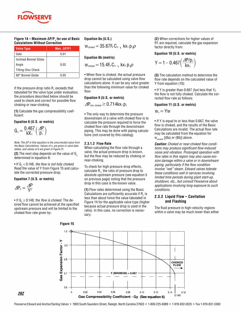
262
Flowserve Edward and Anchor/Darling Valves • 1900 South Saunders Street, Raleigh, North Carolina 27603 • 1-800-225-6989 • 1-919-832-0525 • Fax 1-919-831-3369
Figure14–MaximumΔP/P1 for use of Basic CalculationsWithoutCorrection
ValveType Max.ΔP/P1
Gate 0.01
Inclined Bonnet Globe
Angle
Tilting-Disc Check
0.02
90° Bonnet Globe 0.05
If the pressure-drop ratio R1 exceeds that tabulated for the valve type under evaluation, the procedure described below should be used to check and correct for possible flow choking or near-choking.
(1) Calculate the gas compressibility coef-ficient:
Equation6(U.S.ormetric)
.G kX pP0 467
Ty
1=
Dc m
Note: The ΔP in this equation is the uncorrected value from the Basic Calculations. Values of xT are given in valve data tables, and values of k are given in Figure 21.
(2) The next step depends on the value of Gy determined in equation 6:
• If Gy < 0.148, the flow is not fully choked. Read the value of Y from Figure 15 and calcu-late the corrected pressure drop:
Equation7(U.S.ormetric)
P YP
C 2=D D
• If Gy ≥ 0.148, the flow is choked. The de-sired flow cannot be achieved at the specified upstream pressure and will be limited to the choked flow rate given by:
Equation8a(U.S.)
.w F C kx p35 67choked P V T 1= t
Equation8b(metric)
.w F C kx p15 4choked P V T 1= t
• When flow is choked, the actual pressure drop cannot be calculated using valve flow calculations alone. It can be any valve greater than the following minimum value for choked flow:
Equation9(U.S.ormetric)
.P kx p0 714min. choked T 1$D
• The only way to determine the pressure downstream of a valve with choked flow is to calculate the pressure required to force the choked flow rate through the downstream piping. This may be done with piping calcula-tions (not covered by this catalog).
2.3.1.2 FlowRateWhen calculating the flow rate through a valve, the actual pressure drop is known, but the flow may be reduced by choking or near-choking.
To check for high pressure-drop effects, calculate R1, the ratio of pressure drop to absolute upstream pressure (see equation 5 on previous page) noting that the pressure drop in this case is the known value.
(1) Flow rates determined using the Basic Calculations are sufficiently accurate if R1 is less than about twice the value tabulated in Figure 14 for the applicable valve type (higher because actual pressure drop is used in the ratio). In this case, no correction is neces-sary.
(2) When corrections for higher values of R1 are required, calculate the gas expansion factor directly from:
Equation10(U.S.ormetric)
. /Y kxP p1 0 467
T
1= -
Dc m
(3) The calculation method to determine the flow rate depends on the calculated value of Y from equation (10):
• If Y is greater than 0.667 (but less that 1), the flow is not fully choked. Calculate the cor-rected flow rate as follows:
Equation11(U.S.ormetric)
w Ywc =
• If Y is equal to or less than 0.667, the valve flow is choked, and the results of the Basic Calculations are invalid. The actual flow rate may be calculated from the equation for wchoked [(8a) or (8b)] above.
Caution: Choked or near-choked flow condi-tions may produce significant flow-induced noise and vibration. Prolonged operation with flow rates in this region may also cause ero-sion damage within a valve or in downstream piping, particularly if the flow condition involve “wet” steam. Edward valves tolerate these conditions well in services involving limited time periods during plant start-up, shutdown, etc., but consult Flowserve about applications involving long exposure to such conditions.
2.3.2 LiquidFlow–Cavitationand Flashing
The fluid pressure in high-velocity regions within a valve may be much lower than either
Figure 15

flowserve.com
263
Flowserve Edward and Anchor/Darling Valves • 1900 South Saunders Street, Raleigh, North Carolina 27603 • 1-800-225-6989 • 1-919-832-0525 • Fax 1-919-831-3369
the upstream pressure or the downstream pressure. If the pressure within a valve falls below the vapor pressure (pv) of the liquid, vapor bubbles or cavities may form in the flow stream. Cavitation, flashing and choking may occur. Use the equations and procedures in this section to evaluate these phenomena.
Cavitation and flashing are closely related, and they may be evaluated by calculating a pressure-drop ratio that is slightly different from that used for gas or steam:
Equation12
R p pP
V1
1=
-D
^ h
To evaluate a particular valve and application, find values of Ki and FL from the appropriate valve-data table, find PV values for common liquids given in Figure 25, calculate R2, and perform the following checks:
(1)Cavitation – the sudden and sometimes violent coalescence of the cavities back to the liquid state occurs when the downstream pressure (within the valve or in the down-stream pipe) recovers to above the vapor pressure.
• If R2 < Ki, there should be no significant cavitation or effect on flow or pressure drop. Results of the Basic Calculations require no correction.
• If R2 > Ki, cavitation begins. If the ratio is only slightly greater than Ki, it may be de-tected as an intermittent “ticking” noise near the valve outlet, although pipe insulation may muffle this sound. This stage of cavitation is usually related to tiny vapor cavities that form near the center of vortices in the flow stream, and it generally produces neither damage nor effects on flow characteristics. However, as the pressure drop ratio R2 increases, the noise progresses to a “shh,” then a “roar.”
• If R2 > (Ki + FL2)/2, approximately, larger va-por cavities develop and the risk of cavitation damage (pitting) in the valve or downstream pipe may be a concern if this flow condition is sustained for significant periods of time. Noise may also pose a problem. Still, at this stage, there is usually no significant effect on valve flow characteristics. Results of the Basic Calculations require no correction.
As the pressure-drop ratio increases beyond this point, some valves suffer slight reduc-tions in their CV values, but there is no practical way of correcting pressure drop or flow calculations for this effect. Vibration
and noise increase, ultimately sounding like “rocks and gravel” bouncing in the pipe at about the point where flow becomes choked.
(2)Flashing – the persistence of vapor cavities downstream of the valve occurs when the pressure downstream of the valve remains below the vapor pressure.
• If R2 > 1, flashing occurs, and the flow is choked due to vapor cavities in the flow stream.
(3)Liquidchoking – A slightly different ratio may be used to predict the minimum pressure drop at choked flow conditions. Choking occurs due to vapor cavities near the minimum-area region in the flow stream when:
Equation13
.p pP F0 7 V
L1
$-D 2
^ h
Thus, the minimum pressure drop that will produce choked liquid flow is given by:
Equation14
.P F p p0 7L V1$ -D 2^ h
Note that flow may be choked by either sever cavitation or flashing.
2.3.2.1 PredictingChokedFlowRateIf the result of a Basic Calculation to determine pressure drop exceeds the value determined from equation (13), the Basic Calculation is invalid. the flow used for input cannot be obtained at the specified upstream pressure and temperature. In such a case, of if it is necessary to calculate liquid flow rate through a valve with high-pressure drop, the choked flow rate at specified conditions may be calculated from:
Equation15a(U.S.)
. .w F C F p p63 3 0 7choked P V L V1= -t^ hEquation15b(metric)
..w F C F p p0 727 3choked P V L V1= -t^ h
When flow is choked due to either cavitating or flashing flow, the actual pressure drop cannot be determined from valve calcula-tions. It may be any value greater than the minimum value for choked flow [equation (14)]. As in the case of choked gas or steam flow, the pressure downstream of a valve
must be determined by calculating the pressure required to force the choked flow through the downstream piping. This may be done with piping calculations (not covered by this catalog).
• If the pressure drop from a Basic Calcula-tion was used to determine flow rate, and the pressure drop exceeds the pressure drop of choked flow, the result is invalid. The corrected flow rate may be calculated from equation (15a) or (15b) above.
2.4 Check Valve SizingThe most important difference between check (including stop-check) valves and stop valves, from a flow performance standpoint, is that the check valve disc is opened only by dynamic forces due to fluid flow. The preced-ing calculation methods for flow and pressure drop are valid only if it can be shown that the valve is fully open.
The primary purpose of this section is to provide methods to predict check valve disc opening and to make corrections to pressure-drop calculations if the valve is not fully open. These methods are particularly applicable to sizing valves for new installations, but they are also useful for evaluation of performance of existing valves.
In selecting a stop-check or check valve for a new installation, the first steps require selecting a proper type and pressure class. The Stop and Check Valve Applications Guide section of this catalog should be reviewed carefully when the type is selected, not-ing advantages and disadvantages of each type and considering how they relate to the requirements of the installation. Other sec-tions of this catalog provide pressure ratings to permit selection of the required pressure class.
2.4.1 SizingParameter
The first step in evaluating a stop-check or check valve application is to determine the Sizing Parameter based on the system flow rate and fluid properties:
Equation16(U.S.ormetric)
SP w=
t
Tables in this section provide a Sizing Parameter for full lift (SPFL) for each Edward stop-check and check valve. The amount of opening of any check valve and its effect

264
Flowserve Edward and Anchor/Darling Valves • 1900 South Saunders Street, Raleigh, North Carolina 27603 • 1-800-225-6989 • 1-919-832-0525 • Fax 1-919-831-3369
on pressure drop can be checked simply as follows:
• If SPFL < SP, the valve is fully open. Pressure drop may be calculated using the equations given previously for fully open valves (includ-ing corrections for large pressure drops if required).
• IF SPFL > SP, the valve is not fully open. A smaller size valve or another type should be selected if possible to ensure full opening. If that is not feasible, three additional steps are required to evaluate the opening and pressure drop of the valve under the specified service conditions.
Note: EPRI Report No. NP 5479 (Application Guideline 2.1) uses a “C” factor to calculate the minimum flow velocity required to fully open a check valve. The sizing procedures in this catalog do not employ the “C” factor, but values are given in the valve data tables for readers who prefer to use the EPRI methods. Since the EPRI methods are based on velocity, a flow area is required as a basis. Valve Inlet Diameters presented in data tables are the basis for correlation between flow rate and velocity.
2.4.2 CalculationsforCheckValvesLessThanFullyOpen
If the preceding evaluation revealed an incompletely open check valve, perform the following additional calculations:
Calculatetheflow-rateratio:
Equation17(U.S.ormetric)
R SPSP
FFL
=
Determine the disc operating position:Using the RF value calculated above, deter-mine the valve operating position from Figure 15 (forged-steel valves) or Figures 16-19 (cast-steel valves). Performance curve num-bers for individual cast-steel stop-check and check valves are given in the tabulations with other coefficients. Evaluate the acceptability of the operating position based on recom-mendations in the Check Valve Applications Guide and in the specific sizing guidelines below.
Calculate the pressure drop:Again using the RF value calculated above, determine the pressure drop ratio RP from Figures 15-19, and calculate the valve pres-sure drop at the partially open position:
Equation18(U.S.ormetric)
P R PP FL=D D
Values for ΔPFL for all stop-check and check valves are given in Valve Tables 1 to 5 with other coefficients.
Note: The values of the various valve coefficients given in the tabulations are based on testing of a substantial number of valves. Most are applicable to any line fluid, but those involving check valve lift are influenced by buoyancy. Tabulated values are based on reference test conditions with room-temperature water. SPFL and ΔPFL are slightly higher in applications involving lower-density line fluids. Considering the expected accuracy of these calcula-tions, the following corrections may be considered:
• For water at any temperature and other common liquids – No correction required.
• For steam, air and other common gases at normal operating pressures and tempera-tures – Increase SPFL by 7% and increase ΔPFL by 14%.
2.4.3 SizingGuidelines
Considering the recommendations in the Check Valve Applications Guide section of this catalog and the calculation methods described above, the following specific steps are recommended for sizing check valves for optimum performance and service life (it is assumed that the check valve type and pres-sure class have already been selected before starting this procedure):
(1)Constantflowrate – If the application in-volves a substantially constant flow rate dur-ing all operating conditions, the check valve should be sized to be fully open. This may be accomplished by the following procedure:
• Calculate the check valve sizing parameter (SP) for the application from equation (15). Values of density for water, steam, and air are available in Figures 21-23.
If the flow rate is not given in lb/hr (or kg/hr), refer to the Conversion of Measurement Units section of this catalog to make the necessary calculation.
• Select the valve size with the next smaller SPFL value from valve data tables (Tables 1-5). Make note of the CV, ΔPCO, ΔPFL, Ki, FL and xT values for use in later calculations.
Note: Preferably, there should be a good margin between SP and SPFL to be sure the valve will be fully open. In the specific case of tilting-disc check valves, it is recommend-ed that SPFL be less than 0.83 (SP) to be sure that the disc is fully loaded against its stop (particularly if it is close to a flow disturbance).
• Calculate the pressure drop using the Basic Calculation method in equation (1) and the Cxx value of the valve size selected above. Make the simple checks described above in section 2.2 (Corrections Required With Large Pressure Drops), and make appropriate cor-rections in necessary (this is rarely needed
for a valve sized for constant flow rate, but the check is desirable).
• Evaluate the pressure drop. If it is too high, a larger size or another check valve type should be tried. If it is lower than neces-sary for the application, a smaller and more economical valve (with a lower SPFL) may be evaluated with assurance that it would also be fully open.
• Evaluate the crack-open pressure drop (ΔPCO) to be certain that the system head available at the initiation of flow will initiate valve opening. Note that, for some valves, the crack-open pressure drop exceeds the pres-sure drop for full lift. Preceding calculations might indicate no problem, but it is possible that a valve might not open at all in a low-head application (e.g., gravity flow).
(2)Variableflowrate – If the application involves check valve operation over a range of flow rates, additional calculations are necessary to ensure satisfactory, stable performance at the lowest flow rate without causing excessive pressure drop at the maxi-mum flow condition. This required careful evaluation of specific system operating con-ditions (e.g., are the minimum and maximum flow rates normal operating conditions or infrequent conditions that occur only during start-up or emergency conditions?).
The following options should be considered in selecting the best stop-check or check valve size for variable flow applications:
• The best method, if practical, is to size the valve to be fully open at the minimum flow condition. This may be done by following the first two steps listed above for the constant flow-rate case, but using the minimum flow rate in the sizing parameter (SP) calculation.
The only difference is that the pressure-drop calculations and evaluations in the third and fourth steps must be repeated at normal and maximum flow rates. If the selected valve size is fully open at the minimum flow rate and has an acceptable pressure drop at the maximum flow condition, it should give good overall performance.
• Sometimes a change in valve type pro-vides the best cost-effective solution for variable-flow applications (e.g., use a smaller Flite-Flow stop-check or check valve instead of a 90° bonnet type to provide full lift at the minimum flow condition, but a high CV for low pressure drop at maximum flow).
• Operation at less than full lift may have to be considered.
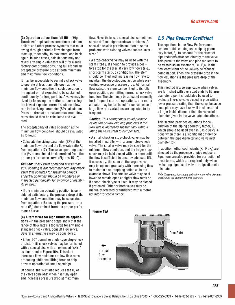
flowserve.com
265
Flowserve Edward and Anchor/Darling Valves • 1900 South Saunders Street, Raleigh, North Carolina 27603 • 1-800-225-6989 • 1-919-832-0525 • Fax 1-919-831-3369
(3)Operationatlessthanfulllift – “High Turndown” applications sometimes exist on boilers and other process systems that must swing through periodic flow changes from start-up, to standby, to maximum, and back again. In such cases, calculations may not reveal any single valve that will offer a satis-factory compromise ensuring full lift and an acceptable pressure drop at both minimum and maximum flow conditions.
It may be acceptable to permit a check valve to operate at less than fully open at the minimum flow condition if such operation is infrequent or not expected to be sustained continuously for long periods. A valve may be sized by following the methods above using the lowest expected normal sustained flow rate in the sizing parameter (SP) calculation. Pressure drop at normal and maximum flow rates should then be calculated and evalu-ated.
The acceptability of valve operation at the minimum flow condition should be evaluated as follows:
• Calculate the sizing parameter (SP) at the minimum flow rate and the flow-rate ratio RF from equation (17). The valve operating posi-tion (% open) should be determined from the proper performance curve (Figures 15-19).
Caution: Check valve operation at less than 25% opening is not recommended. Any check valve that operates for sustained periods at partial openings should be monitored or inspected periodically for evidence of instabil-ity or wear.
• If the minimum operating position is con-sidered satisfactory, the pressure drop at the minimum flow condition may be calculated from equation (18), using the pressure-drop ratio (Rp) determined from the proper perfor-mance curve.
(4)Alternativesforhighturndownapplica-tions – If the preceding steps show that the range of flow rates is too large for any single standard check valve, consult Flowserve. Several alternatives may be considered:
• Either 90° bonnet or angle-type stop-check or piston-lift check valves may be furnished with a special disc with an extended “skirt” as illustrated in Figure 15A. This skirt increases flow resistance at low flow rates, producing additional lifting force to help prevent operation at small openings.
Of course, the skirt also reduces the CV of the valve somewhat when it is fully open and increases pressure drop at maximum
flow. Nevertheless, a special disc sometimes solves difficult high turndown problems. A special disc also permits solution of some problems with existing valves that are “over-sized.”
• A stop-check valve may be used with the stem lifted just enough to provide a posi-tive stop for the disc at very low flows (e.g., short-term start-up conditions). The stem should be lifted with increasing flow rate to maintain the disc-stopping action while pre-venting excessive pressure drop. At normal flow rates, the stem can be lifted to its fully open position, permitting normal check valve function. The stem may be actuated manually for infrequent start-up operations, or a motor actuator may be furnished for convenience if large flow rate variations are expected to be frequent.
Caution: This arrangement could produce cavitation or flow-choking problems if the flow rate is increased substantially without lifting the valve stem to compensate.
• A small check or stop-check valve may be installed in parallel with a larger stop-check valve. The smaller valve may be sized for the minimum flow condition, and the larger stop-check may be held closed with the stem until the flow is sufficient to ensurev adequate lift. If necessary, the stem on the larger valve may be opened gradually with increasing flow to maintain disc-stopping action as in the example above. The smaller valve may be al-lowed to remain open at higher flow rates or, if a stop-check type is used, it may be closed if preferred. Either or both valves may be manually actuated or furnished with a motor actuator for convenience.
2.5 Pipe Reducer CoefficientThe equations in the Flow Performance section of this catalog use a piping geom-etry factor, Fp, to account for the effect of pipe reducers attached directly to the valve. This permits the valve and pipe reducers to be treated as an assembly, i.e., FpCV is the flow coefficient of the valve/pipe reducer combination. Then, the pressure drop in the flow equations is the pressure drop of the assembly.
This method is also applicable when valves are furnished with oversized ends to fit larger diameter pipe. It should also be used to evaluate line-size valves used in pipe with a lower pressure rating than the valve, because such pipe may have less wall thickness and a larger inside diameter than the valve inlet diameter given in the valve data tabulations.
This section provides equations for cal-culation of the piping geometry factor, Fp, which should be used even in Basic Calcula-tions when there is a significant difference between the pipe diameter and valve inlet diameter (d).
In addition, other coefficients (K1, FL, xT) are affected by the presence of pipe reducers. Equations are also provided for correction of these terms, which are required only when evaluating significant valve-to-pipe diameter mismatch.
Note: These equations apply only where the valve diameter is less than the connecting pipe diameter.
Figure 15A
normalflowdirection
Disc Skirt

266
Flowserve Edward and Anchor/Darling Valves • 1900 South Saunders Street, Raleigh, North Carolina 27603 • 1-800-225-6989 • 1-919-832-0525 • Fax 1-919-831-3369
2.5.1 PipeGeometryFactor
Calculate upstream loss coefficient:
Equation1-1(U.S.ormetric)
.K Dd0 5 11
1
2
= -2
c m; E
Calculate downstream loss coefficient:
Equation1-2(U.S.ormetric)
K Dd12
2
2
= -2
c m; E
Summation:
Equation1-3(U.S.ormetric)
K K K1 2= +/
Equation1-4a(U.S.)
F
dC1 890
1P
y2
2=+ K c m/
Equation1-4b(metric)
F
dC1 486
1P
y2
2=+ Kc m/
Note: If D1 and D2 are not the same, use of FP calculated in this manner accounts for energy losses associated with flow contraction and expansion, and the pressure drop cal-culated using this factor represents energy loss. Bernoulli effects may cuase a different static pressure change between upstream and downstream pipes.
2.5.2 Other Coefficients
Correction of values of K1, FL and xT requires an initial calculation of a Bernoulli coefficient to account for static pressure change in the inlet reducer:
Equation1-5(U.S.ormetric)
K Dd1B1
1
4
= - c m
Then, corrected values of each coefficient may be calculated, using the corresponding value from valve data tables as input:
Equation1-6a(U.S.)
K
KK KF d
C1890
1ii
i
BP
V1 12
2=+
+2 b bl l; E
Equation1-6b(metric)
K
K K KF dC1 468
1ii
iBP
V1 1 2
2=+ +
2 ^ bh l; E
Equation1-7a(U.S.)
F
FK K
dCF 1
890
1LL
L
B VP
1 12
2=
++
2 b bl l
Equation1-7b(metric)
F
F K K dCF 1 468
1LL
LB
VP 1 1 2
2=
+ +2 ^ bh l
Equation1-8a(U.S.)
xF x K K
dC
x
1 1000
TT
PT B V
T
2 1 12
2=+
+^ bh l; E
Equation1-8b(metric)
xF x K K d
Cx
1 416TT
P T BV
T
21 1 2
2=+ +^ bh l; E
where: Ki, FL and xT are values from valve data tables; Kii, FLL and xTT are corrected values for valve/reducer assembly.
CV valve flow coefficient. See Valve Reference Data.
d valve-end inside diameter, inches, (mm). See Valve Reference Data.
D1 inside diameter of upstream pipe, inches, (mm). See Pipe Data Section.
D2 inside diameter of downstream pipe, inches, (mm). See Pipe Data Section.
FL liquid-pressure recovery coefficient, dimensionless*
Fp piping-geometry factor, dimensionless
K1 pressure-loss coefficient for inlet reducer, dimensionless
K2 pressure-loss coefficient for outlet reducer, dimensionless
KB1 pressure change (Bernoulli) coefficient for inlet reducer, dimensionless
∑K K1 + K2, dimensionless
Ki incipient-cavitation coefficient, dimensionless*
xT terminal value of ΔP/p1 for choked gas or steam flow, dimensionless
Nomenclature
*Double subscripts (e.g. Kii) represent values corrected for effects of pipe reducers.

flowserve.com
267
Flowserve Edward and Anchor/Darling Valves • 1900 South Saunders Street, Raleigh, North Carolina 27603 • 1-800-225-6989 • 1-919-832-0525 • Fax 1-919-831-3369
Table 1 – Edward Cast Steel Globe Flow Coefficients
Black numerals are in U.S. customary units or dimensionless Colored numerals are in metric units
Size StopandCheckValves CheckValveCoefficients Perf.Curves Fig. 17NPS DN CV FL xT Ki d ΔPCO ΔPFL SPFL C
Class900(PN150) Figure No. 4016/4016Y, 4316Y Stop valves, 4006/4006Y, 4306Y Stop-Check valves, 4094/4094Y, 4394Y Check valves3 80 110 0.96 0.60
0.102.87 72.9 0.92 0.063 1.5 0.10 8510 964 53 4
4 100 200 0.97 0.60 3.87 98.2 1.3 0.090 2.3 0.16 19,500 2210 66 55 125 305 0.97 0.61 4.75 121 1.3 0.092 2.5 0.18 30,600 3470 69 46 150 530 0.81 0.42
0.07
5.75 146 1.2 0.085 1.5 0.10 41,500 4700 64 38 200 910 0.81 0.42 7.50 191 1.3 0.093 1.5 0.10 69,500 7870 63 210 250 1400 0.81 0.42 9.37 238 1.6 0.11 1.8 0.12 119,000 13,500 69 112 300 2000 0.81 0.42 11.12 282 1.8 0.12 2.1 0.14 182,000 20,600 75 214 350 2400 0.81 0.42 12.25 311 1.6 0.11 1.9 0.13 211,000 23,900 72 2
See note following section 2.4.1 for discussion of C factor.
Class1500(PN260) Figure No. 2016, 7516/7516Y Stop valves, 2006Y, 7506/7506Y Stop-Check valves, 2094Y, 7594/7594Y Check valves2.5 65 72 0.92 0.54
0.082.25 57.2 0.76 0.052 1.3 0.091 5230 592 53 5
3 80 110 0.89 0.51 2.75 69.9 0.92 0.063 1.5 0.10 8510 964 57 44 100 200 0.85 0.47 3.62 91.9 1.3 0.088 2.3 0.16 19,300 2190 75 55 125 300 0.83 0.44
0.07
4.37 111 1.2 0.080 2.2 0.15 28,600 3240 76 46 150 465 0.80 0.42 5.37 136 1.4 0.094 1.4 0.096 35,000 3960 62 28 200 790 0.81 0.42 7.00 178 1.6 0.11 1.4 0.097 59,300 6720 62 110 250 1250 0.81 0.42 8.75 222 1.5 0.10 1.4 0.100 93,900 10,600 63 112 300 1750 0.81 0.42 10.37 263 1.5 0.11 1.8 0.12 147,000 16,600 70 314 350 2100 0.81 0.42 11.37 289 1.7 0.12 2.1 0.14 190,000 21,500 75 3

268
Flowserve Edward and Anchor/Darling Valves • 1900 South Saunders Street, Raleigh, North Carolina 27603 • 1-800-225-6989 • 1-919-832-0525 • Fax 1-919-831-3369
Figure16–EdwardCastSteelGlobePistonLiftCheckValvePerformanceCurves
Figure 16A
Figure 16B

flowserve.com
269
Flowserve Edward and Anchor/Darling Valves • 1900 South Saunders Street, Raleigh, North Carolina 27603 • 1-800-225-6989 • 1-919-832-0525 • Fax 1-919-831-3369
Table 2 – Edward Cast Steel Angle Valve Flow Coefficients
Black numerals are in U.S. customary units or dimensionless Colored numerals are in metric units
Size StopandCheckValves CheckValveCoefficient Perf.Curves Fig. 17NPS DN CV FL xT Ki d ΔPCO ΔPFL SPFL C
Class900(PN150) Figure No. 4017/4017Y, 4317Y Stop valves, 4007/4007Y, 4307Y Stop-Check valves, 4095/4095Y, 4395Y Check valves3 80 180 0.62 0.24
0.08
2.87 72.9 0.92 0.063 0.64 0.044 8980 1020 56 54 100 325 0.62 0.25 3.87 98.2 1.5 0.10 1.2 0.081 22,200 2510 75 55 125 485 0.63 0.25 4.75 121 1.2 0.083 1.0 0.072 31,200 3530 70 56 150 790 0.63 0.25 5.75 146 1.3 0.092 1.0 0.071 50,900 5770 78 38 200 1350 0.63 0.25 7.50 190 1.4 0.099 1.0 0.071 86,600 9810 78 310 250 2100 0.63 0.25 9.37 238 1.7 0.12 1.3 0.090 152,000 17,200 88 312 300 2950 0.63 0.25 11.12 282 1.8 0.13 1.4 0.093 218,000 24,700 90 214 350 3600 0.63 0.25 12.25 311 1.5 0.10 1.3 0.091 261,000 29,600 89 216 400 6450 0.56 0.19
0.06
14.00 356 1.9 0.13 0.74 0.051 350,000 39,700 91 218 450 * * * 15.75 400 * * * * * * * *20 500 10,000 0.56 0.19 17.50 444 1.7 0.11 0.76 0.052 553,000 62,600 92 324 600 14,500 0.56 0.19 21.00 533 2.6 0.18 1.1 0.073 940,000 106,000 109 3
Class1500(PN260) Figure No. 2017Y, 7517/7517Y Stop valves, 2007Y, 7507/7507Y Stop-Check valves, 2095Y, 7595/7595Y Check valves2.5 65 115 0.59 0.22
0.06
2.25 57.2 0.75 0.052 0.58 0.040 5560 630 56 63 80 180 0.57 0.21 2.75 69.9 0.92 0.063 0.64 0.044 8980 1020 60 54 100 320 0.55 0.19 3.62 91.9 1.50 0.10 1.20 0.081 22,000 2490 86 55 125 475 0.54 0.18 4.37 111 1.30 0.093 1.20 0.083 33,000 3740 88 56 150 690 0.63 0.25
0.08
5.37 136 1.50 0.10 1.00 0.069 43,800 4970 77 38 200 1150 0.63 0.25 7.00 178 1.60 0.11 0.99 0.068 73,900 8370 77 310 250 1850 0.63 0.25 8.75 222 1.60 0.11 1.20 0.083 127,000 14,400 85 312 300 2550 0.63 0.25 10.37 263 1.80 0.13 1.40 0.094 190,000 21,500 90 314 350 3100 0.63 0.25 11.37 289 1.70 0.12 1.30 0.091 225,000 25,500 89 316 400 5550 0.56 0.19
0.0613.00 330 2.00 0.14 0.79 0.055 313,000 35,400 94 3
18 450 5350 0.54 0.19 14.62 371 2.00 0.14 0.86 0.059 313,000 35,400 75 320 500 * * * * 16.37 416 * * * * * * * *24 600 * * * * 19.62 498 * * * * * * * *
See note following section 2.4.1 for discussion of C factor.
* Consult Flowserve Edward Valves Sales Representative

270
Flowserve Edward and Anchor/Darling Valves • 1900 South Saunders Street, Raleigh, North Carolina 27603 • 1-800-225-6989 • 1-919-832-0525 • Fax 1-919-831-3369
Figure 17 – Edward Cast Steel Angle Piston Lift Check Valve Performance Curves
Figure 17A
Figure 17B
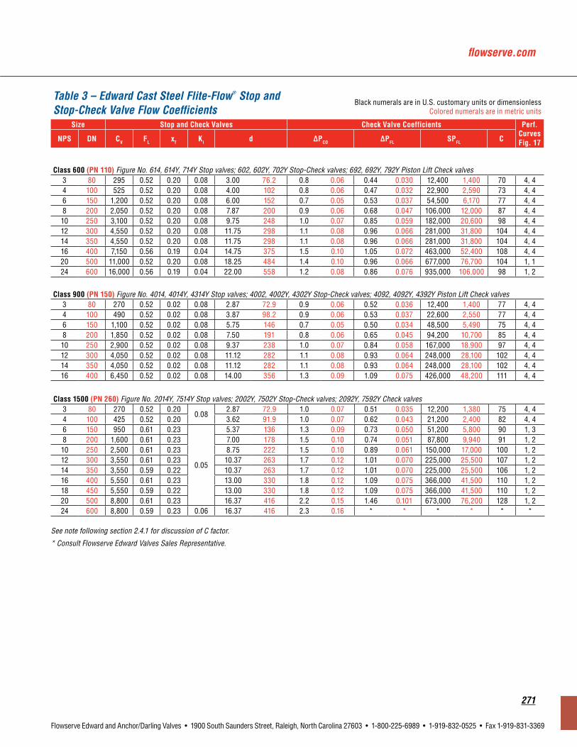
flowserve.com
271
Flowserve Edward and Anchor/Darling Valves • 1900 South Saunders Street, Raleigh, North Carolina 27603 • 1-800-225-6989 • 1-919-832-0525 • Fax 1-919-831-3369
Class1500(PN260) Figure No. 2014Y, 7514Y Stop valves; 2002Y, 7502Y Stop-Check valves; 2092Y, 7592Y Check valves3 80 270 0.52 0.20
0.082.87 72.9 1.0 0.07 0.51 0.035 12,200 1,380 75 4, 4
4 100 425 0.52 0.20 3.62 91.9 1.0 0.07 0.62 0.043 21,200 2,400 82 4, 46 150 950 0.61 0.23
0.05
5.37 136 1.3 0.09 0.73 0.050 51,200 5,800 90 1, 38 200 1,600 0.61 0.23 7.00 178 1.5 0.10 0.74 0.051 87,800 9,940 91 1, 210 250 2,500 0.61 0.23 8.75 222 1.5 0.10 0.89 0.061 150,000 17,000 100 1, 212 300 3,550 0.61 0.23 10.37 263 1.7 0.12 1.01 0.070 225,000 25,500 107 1, 214 350 3,550 0.59 0.22 10.37 263 1.7 0.12 1.01 0.070 225,000 25,500 106 1, 216 400 5,550 0.61 0.23 13.00 330 1.8 0.12 1.09 0.075 366,000 41,500 110 1, 218 450 5,550 0.59 0.22 13.00 330 1.8 0.12 1.09 0.075 366,000 41,500 110 1, 220 500 8,800 0.61 0.23 16.37 416 2.2 0.15 1.46 0.101 673,000 76,200 128 1, 224 600 8,800 0.59 0.23 0.06 16.37 416 2.3 0.16 * * * * * *
See note following section 2.4.1 for discussion of C factor.
* Consult Flowserve Edward Valves Sales Representative.
Class600(PN110) Figure No. 614, 614Y, 714Y Stop valves; 602, 602Y, 702Y Stop-Check valves; 692, 692Y, 792Y Piston Lift Check valves3 80 295 0.52 0.20 0.08 3.00 76.2 0.8 0.06 0.44 0.030 12,400 1,400 70 4, 44 100 525 0.52 0.20 0.08 4.00 102 0.8 0.06 0.47 0.032 22,900 2,590 73 4, 46 150 1,200 0.52 0.20 0.08 6.00 152 0.7 0.05 0.53 0.037 54,500 6,170 77 4, 48 200 2,050 0.52 0.20 0.08 7.87 200 0.9 0.06 0.68 0.047 106,000 12,000 87 4, 410 250 3,100 0.52 0.20 0.08 9.75 248 1.0 0.07 0.85 0.059 182,000 20,600 98 4, 412 300 4,550 0.52 0.20 0.08 11.75 298 1.1 0.08 0.96 0.066 281,000 31,800 104 4, 414 350 4,550 0.52 0.20 0.08 11.75 298 1.1 0.08 0.96 0.066 281,000 31,800 104 4, 416 400 7,150 0.56 0.19 0.04 14.75 375 1.5 0.10 1.05 0.072 463,000 52,400 108 4, 420 500 11,000 0.52 0.20 0.08 18.25 484 1.4 0.10 0.96 0.066 677,000 76,700 104 1, 124 600 16,000 0.56 0.19 0.04 22.00 558 1.2 0.08 0.86 0.076 935,000 106,000 98 1, 2
Class900(PN150) Figure No. 4014, 4014Y, 4314Y Stop valves; 4002, 4002Y, 4302Y Stop-Check valves; 4092, 4092Y, 4392Y Piston Lift Check valves3 80 270 0.52 0.02 0.08 2.87 72.9 0.9 0.06 0.52 0.036 12,400 1,400 77 4, 44 100 490 0.52 0.02 0.08 3.87 98.2 0.9 0.06 0.53 0.037 22,600 2,550 77 4, 46 150 1,100 0.52 0.02 0.08 5.75 146 0.7 0.05 0.50 0.034 48,500 5,490 75 4, 48 200 1,850 0.52 0.02 0.08 7.50 191 0.8 0.06 0.65 0.045 94,200 10,700 85 4, 410 250 2,900 0.52 0.02 0.08 9.37 238 1.0 0.07 0.84 0.058 167,000 18,900 97 4, 412 300 4,050 0.52 0.02 0.08 11.12 282 1.1 0.08 0.93 0.064 248,000 28,100 102 4, 414 350 4,050 0.52 0.02 0.08 11.12 282 1.1 0.08 0.93 0.064 248,000 28,100 102 4, 416 400 6,450 0.52 0.02 0.08 14.00 356 1.3 0.09 1.09 0.075 426,000 48,200 111 4, 4
Table 3 – Edward Cast Steel Flite-Flow® Stop and Stop-Check Valve Flow Coefficients
Black numerals are in U.S. customary units or dimensionless Colored numerals are in metric units
Size StopandCheckValves CheckValveCoefficients Perf.Curves Fig. 17NPS DN CV FL xT Ki d ΔPCO ΔPFL SPFL C
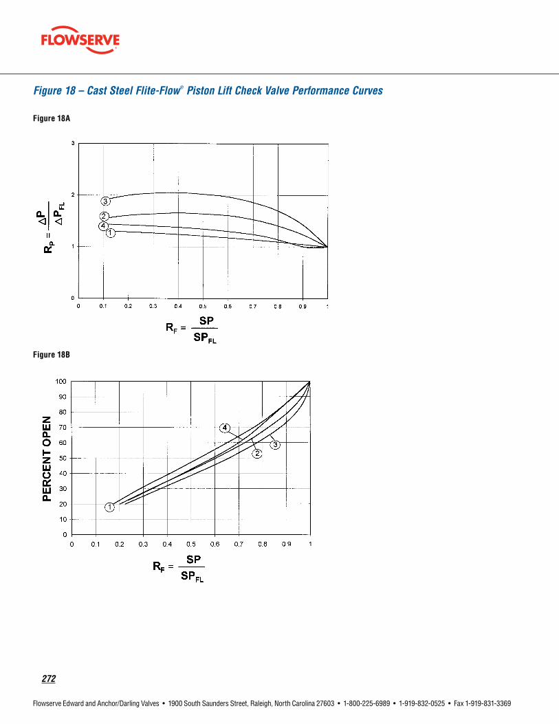
272
Flowserve Edward and Anchor/Darling Valves • 1900 South Saunders Street, Raleigh, North Carolina 27603 • 1-800-225-6989 • 1-919-832-0525 • Fax 1-919-831-3369
Figure 18 – Cast Steel Flite-Flow® Piston Lift Check Valve Performance Curves
Figure 18A
Figure 18B

flowserve.com
273
Flowserve Edward and Anchor/Darling Valves • 1900 South Saunders Street, Raleigh, North Carolina 27603 • 1-800-225-6989 • 1-919-832-0525 • Fax 1-919-831-3369
Table 4 – Edward Cast Steel Tilting-Disc check Valve Flow Coefficients1
Black numerals are in U.S. customary units or dimensionless Colored numerals are in metric units
Size CheckValveFlowCoefficients CheckValveCoefficients Perf.Curves
Fig. 20
NPS DN CV FL xT Ki d ΔPFL SPFL C
Class600(PN110) Figure No. 670Y, 770Y
6 150 1110 0.57 0.20
0.05
6.00 152 0.80 0.055 62,300 7,060 88 1
8 200 1850 0.57 0.20 7.87 200 1.0 0.069 115,000 13,000 95 1
10 250 2850 0.57 0.20 9.75 248 1.1 0.076 187,000 21,200 100 1
12 300 4100 0.57 0.20 11.75 298 1.2 0.083 285,000 32,300 105 1
14 350 4050 0.56 0.20 12.87 327 1.2 0.083 285,000 32,300 88 1
16 400 6500 0.57 0.20 14.75 375 1.4 0.097 481,000 54,500 113 1
18 450 8100 0.57 0.20 16.50 419 1.5 0.10 622,000 70,500 116 1
20 500 9950 0.57 0.20 18.25 464 1.6 0.11 786,000 89,000 120 1
Class900(PN150) Figure No. 970Y, 4370Y
2.5 65 195 0.44 0.12 0.02 2.25 57.2 1.0 0.069 12,200 1,380 123 1
3 80 245 0.57 0.20
0.05
2.87 72.9 0.60 0.041 12,200 1,380 75 1
4 100 215 0.59 0.23 3.87 98.2 0.80 0.055 12,200 1,380 41 1
6 150 990 0.57 0.20 5.75 146 0.80 0.055 56,800 6,430 87 1
8 200 1700 0.57 0.20 7.50 190 0.80 0.055 97,000 11,000 88 2
10 250 2400 0.56 0.20 9.37 238 0.90 0.062 145,000 16,400 84 2
12 300 3450 0.56 0.20 11.12 282 1.1 0.076 233,000 26,400 96 1
14 350 3300 0.56 0.20 12.25 311 1.3 0.090 233,000 26,400 79 1
16 400 4950 0.56 0.20 14.00 356 1.3 0.090 360,000 40,800 94 1
18 450 4700 0.57 0.21 15.75 400 1.5 0.10 360,000 40,800 74 1
20 500 9150 0.57 0.20 17.50 444 1.2 0.083 713,000 80,800 119 1
Class1500(PN260) Figure No. 1570Y, 2070Y
2.5 65 195 0.44 0.12 0.02 2.25 57.2 1.0 0.069 12,200 1,380 123 1
3 80 245 0.52 0.17
0.05
2.75 69.9 0.60 0.041 12,200 1,380 82 1
4 100 225 0.57 0.22 3.62 91.9 0.70 0.048 12,200 1,380 47 1
6 150 970 0.51 0.16 5.37 136 0.90 0.062 56,800 6,430 100 1
8 200 1650 0.51 0.16 7.00 178 0.90 0.062 97,000 11,000 101 2
10 250 2400 0.54 0.18 8.75 222 0.90 0.062 145,000 16,400 96 2
12 300 3450 0.53 0.17 10.37 263 1.1 0.076 233,000 26,400 110 1
14 350 3400 0.56 0.20 11.37 289 1.2 0.083 233,000 26,400 92 1
16 400 5050 0.57 0.20 13.00 330 1.3 0.090 360,000 40,800 108 1
18 450 4900 0.56 0.20 14.62 371 1.4 0.097 360,000 40,800 86 1
24 600 10,500 0.56 0.20 19.62 498 1.5 0.10 824,000 93,400 109 1
See note following section 2.4.1 for discussion of C factor.1 Crack open pressure drop ΔPCO values are generally less than 0.25 psi (0.01 bar).

274
Flowserve Edward and Anchor/Darling Valves • 1900 South Saunders Street, Raleigh, North Carolina 27603 • 1-800-225-6989 • 1-919-832-0525 • Fax 1-919-831-3369
Figure 19 – Tilting-Disc Check Valve Performance Curves
Figure 19A
Figure 19B

flowserve.com
275
Flowserve Edward and Anchor/Darling Valves • 1900 South Saunders Street, Raleigh, North Carolina 27603 • 1-800-225-6989 • 1-919-832-0525 • Fax 1-919-831-3369
Table 5 – Edward Cast Steel Equiwedge® Gate Valve Flow Coefficients
Black numerals are in U.S. customary units or dimensionless Colored numerals are in metric units
RegularPortGateValves
SizeCV FL XT Ki d
NPS DN
Class600(PN110) Figure No. 1611/ 1611Y, 1711Y Stop valves
2.5 65 380 0.77 0.25 0.02 2.50 63.5
3.0 80 610 0.44 0.10 0.02 3.00 76.2
4.0 100 1250 0.41 0.08 0.03 4.00 102
6.0 150 3250 0.40 0.07 0.02 6.00 152
8.0 200 5300 0.35 0.06 0.02 7.87 200
10.0 250 8550 0.34 0.06 0.01 9.75 248
12.0 300 12,000 0.31 0.05 0.01 11.75 298
14.0 350 14,000 0.32 0.05 0.01 12.87 327
16.0 400 18,500 0.32 0.05 0.01 14.75 375
18.0 450 25,500 0.30 0.05 0.01 16.50 419
20.0 500 30,500 0.31 0.05 0.01 18.25 464
22.0 550 36,500 0.30 0.05 0.01 20.12 511
24.0 600 46,500 0.30 0.05 0.01 22.00 559
26.0 650 53,500 0.30 0.05 0.01 23.75 603
28.0 700 62,500 0.29 0.04 0.01 25.50 648
— — — — — — — —
— — — — — — — —
Class600(PN110) Figure No. 1611BY, 1711BY Stop valves
— — — — — — — —
— — — — — — — —
— — — — — — — —
— — — — — — — —
8x6x8 200x150x200 2650 0.33 0.07 0.03 7.87 200
10x8x10 250x200x250 4500 0.32 0.07 0.02 9.75 248
12x10x12 300x250x300 7100 0.32 0.06 0.02 11.75 298
14x12x14 350x300x350 9900 0.32 0.06 0.02 12.87 327
16x14x16 400x350x400 12,000 0.31 0.06 0.02 14.75 375
18x16x18 450x400x450 17,500 0.29 0.05 0.01 16.50 419
20x18x20 500x450x500 22,000 0.30 0.06 0.02 18.25 464
22x20x22 550x500x550 29,000 0.28 0.05 0.01 20.12 511
24x20x24 600x500x600 24,500 0.30 0.06 0.02 22.00 559
26x22x26 650x550x650 30,000 0.30 0.06 0.02 23.75 603
28x24x28 700x600x700 40,500 0.29 0.05 0.01 25.50 648
30x26x30 750x650x750 46,500 0.29 0.05 0.01 27.37 695
32x28x32 800x700x800 52,000 0.30 0.05 0.01 29.25 743
VenturiPortGateValves
SizeCV FL XT Ki d
NPS DN
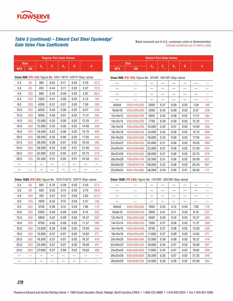
276
Flowserve Edward and Anchor/Darling Valves • 1900 South Saunders Street, Raleigh, North Carolina 27603 • 1-800-225-6989 • 1-919-832-0525 • Fax 1-919-831-3369
Class900(PN150) Figure No. 1911/ 1911Y, 14311Y Stop valves
2.5 65 380 0.63 0.17 0.02 2.25 57.2
3.0 80 455 0.44 0.11 0.03 2.87 72.9
4.0 100 990 0.42 0.09 0.02 3.87 98.2
6.0 150 2350 0.41 0.09 0.02 5.75 146
8.0 200 4200 0.37 0.07 0.02 7.50 190
10.0 250 6250 0.40 0.08 0.02 9.37 238
12.0 300 9500 0.36 0.07 0.02 11.12 282
14.0 350 12,000 0.35 0.06 0.02 12.25 311
16.0 400 15,000 0.35 0.06 0.02 14.00 356
18.0 450 19,500 0.33 0.06 0.02 15.75 400
20.0 500 26,000 0.35 0.06 0.02 17.50 444
22.0 550 28,000 0.38 0.07 0.02 19.25 489
24.0 600 38,000 0.32 0.05 0.01 21.00 533
26.0 650 45,000 0.32 0.05 0.01 22.75 578
28.0 700 52,500 0.31 0.05 0.01 24.50 622
— — — — — — — —
— — — — — — — —
RegularPortGateValves
SizeCV FL XT Ki d
NPS DN
Class1500(PN260) Figure No. 11511/11511Y, 12011Y Stop valves
2.5 65 305 0.78 0.26 0.02 2.25 57.2
3.0 80 420 0.52 0.14 0.03 2.75 69.9
4.0 100 760 0.47 0.12 0.03 3.62 91.9
6.0 150 1650 0.54 0.15 0.04 5.37 136
8.0 200 3150 0.48 0.12 0.03 7.00 178
10.0 250 5500 0.40 0.08 0.02 8.75 222
12.0 300 6850 0.42 0.09 0.02 10.37 263
14.0 350 9700 0.40 0.08 0.02 11.37 289
16.0 400 12,000 0.39 0.08 0.02 13.00 330
18.0 450 15,000 0.37 0.07 0.02 14.62 371
20.0 500 18,500 0.37 0.07 0.02 16.37 416
22.0 550 23,000 0.37 0.07 0.02 18.00 457
24.0 600 27,000 0.37 0.08 0.02 19.62 498
— — — — — — — —
— — — — — — — —
VenturiPortGateValves
SizeCV FL XT Ki d
NPS DN
Class900(PN150) Figure No. 1911BY, 14311BY Stop valves
— — — — — — — —
— — — — — — — —
— — — — — — — —
— — — — — — — —
8x6x8 200x150x200 2000 0.37 0.09 0.03 7.50 190
10x8x10 250x200x250 3500 0.35 0.08 0.02 9.37 238
12x10x12 300x250x300 5950 0.35 0.08 0.02 11.12 282
14x12x14 350x300x350 7700 0.39 0.09 0.03 12.25 311
16x14x16 400x350x400 10,000 0.35 0.07 0.02 14.00 356
18x16x18 450x400x450 14,000 0.32 0.06 0.02 15.75 400
20x18x20 500x450x500 18,000 0.32 0.06 0.02 17.50 444
22x20x22 550x500x550 25,000 0.31 0.06 0.02 19.25 489
24x20x24 600x500x600 23,000 0.31 0.06 0.02 21.00 533
26x22x26 650x550x650 28,000 0.31 0.06 0.02 22.75 578
28x24x28 700x600x700 33,500 0.31 0.06 0.02 24.50 622
30x26x30 750x650x750 38,000 0.32 0.06 0.02 26.25 667
32x28x32 800x700x800 48,000 0.29 0.05 0.01 28.00 711
Class1500(PN260) Figure No. 11511BY, 12011BY Stop valves
— — — — — — — —
— — — — — — — —
— — — — — — — —
— — — — — — — —
8x6x8 200x150x200 1650 0.43 0.12 0.04 7.00 178
10x8x10 250x200x250 2950 0.41 0.11 0.03 8.75 222
12x10x12 300x250x300 4500 0.40 0.10 0.03 10.37 263
14x12x14 350x300x350 7050 0.37 0.08 0.02 11.37 289
16x14x16 400x350x400 8700 0.37 0.08 0.02 13.00 330
18x16x18 450x400x450 11,000 0.37 0.08 0.02 14.62 371
20x18x20 500x450x500 13,500 0.36 0.08 0.02 16.37 416
22x20x22 550x500x550 18,000 0.34 0.07 0.02 18.00 457
24x20x24 600x500x600 17,000 0.35 0.07 0.02 19.62 498
26x22x26 650x550x650 20,500 0.35 0.07 0.02 21.25 540
28x24x28 700x600x700 24,000 0.36 0.08 0.02 23.00 584
Table 5 (continued) – Edward Cast Steel Equiwedge® Gate Valve Flow Coefficients
Black numerals are in U.S. customary units or dimensionless Colored numerals are in metric units

flowserve.com
277
Flowserve Edward and Anchor/Darling Valves • 1900 South Saunders Street, Raleigh, North Carolina 27603 • 1-800-225-6989 • 1-919-832-0525 • Fax 1-919-831-3369
0.05 15 4.9 0.46 0.31 0.07 — — — — 0.464 11.80.75 20 6.1 0.52 0.36 0.09 — — — — 0.612 15.51.00 25 11 0.55 0.38 0.10 6.1 0.51 0.36 0.09 0.815 20.71.50 40 32 0.62 0.39 0.13 11 0.53 0.37 0.09 1.338 34.02.00 50 50 0.68 0.40 0.15 32 0.57 0.37 0.11 1.687 42.82.50 65 — — — — 50 0.59 0.37 0.12 2.125 54.0
Table 6 – Edward Forged Steel Hermavalve® Flow Coefficients
Black numerals are in U.S. customary units or dimensionless Colored numerals are in metric units
NPS DNRegularPortHermavalvesFig.No.
15004/15104,15008/15108,16004,16008ReducedPortHermavalvesFig.No.
15014/15114,15018/15118,16014,16018 dCV FL XT Ki CV FL XT Ki

278
Flowserve Edward and Anchor/Darling Valves • 1900 South Saunders Street, Raleigh, North Carolina 27603 • 1-800-225-6989 • 1-919-832-0525 • Fax 1-919-831-3369
Table 7 – Forged Steel Univalve® Flow Coefficients
Black numerals are in U.S. customary units or dimensionless Colored numerals are in metric units
Size StopandCheckValves CheckValves*withSprings(Std.) CheckValves*withoutSprings
NPS DN CV FL xT Ki d ΔPFL SPFL C ΔPFL SPFL C
Class1500(PN260) All Stop valves, all Stop-Check valves, all Piston Check valves0.50 15 7.0
0.66 0.27 0.16
0.464 11.8
4.0 0.28
886 100 210
1.0 0.069
443 50.2 1050.75 20 12 0.612 15.5 1520 172 207 760 86.0 1031.00 25 12 0.815 20.7 1520 172 117 760 86.0 581.25 32 42 1.160 29.5 5320 602 201 2660 301 1011.50 40 40 1.338 34.0 5060 574 144 2530 287 722.00 50 68 1.687 42.8 8610 975 154 4300 488 772.50 65 110 2.125 54.0 13,900 1580 157 6960 789 793.00 80 100 2.624 66.6 12,700 1430 94 6330 717 474.00 100 85 3.438 87.3 10,800 1220 46 5380 609 23
Class2500(PN420) All Stop valves, all Stop-Check valves, all Piston Check valves0.50 15 7.0
0.63 0.24 0.15
0.464 11.8
4.0 0.28
886 100 210
1.0 0.069
443 50.2 1050.75 20 12 0.612 15.5 760 86.0 103 380 43.0 521.00 25 11 0.599 15.2 1390 158 198 696 78.9 991.25 32 30 0.896 22.8 3800 430 241 1900 215 1211.50 40 28 1.100 28.0 3540 401 149 1770 201 752.00 50 70 1.503 38.2 8860 1000 200 4430 502 1002.50 65 100 1.771 45.0 12,700 1430 206 6330 717 1033.00 80 100 2.300 58.4 12,700 1430 122 6330 717 614.00 100 90 3.152 80.1 11,400 1290 58 5700 645 29
NOTES: See Table 9 for ΔPCO. See notes following section 2.4.1 for discussion of C factor.
* Stop-check valves are only furnished without springs.
Class600(PN110) Figure No. 848/848Y Stop valve, 868/868Y Stop-Check valve, 838/838Y Piston Check valve0.25 8 1.4
0.72 0.30 0.20
0.364 9.2
5.0 0.34
198 22.4 76
0.6 0.041
68.6 7.77 260.38 10 3.3 0.493 12.5 467 52.9 98 162 18.3 340.50 15 3.3 0.546 13.9 467 52.9 80 162 18.3 280.75 20 5.7 0.742 18.8 722 81.8 67 250 28.3 231.00 25 13.5 0.957 24.3 1910 216 106 662 75.0 371.25 32 23.5 1.278 32.5 3330 377 104 1150 131 361.50 40 37.5 1.500 38.1 5290 600 120 1830 208 422.00 50 48.5 1.939 49.3 6860 778 93 2380 269 32
Table 8 – Forged Steel Inclined Bonnet Valve Flow Coefficients
Black numerals are in U.S. customary units or dimensionless Colored numerals are in metric units
Size StopandCheckValves CheckValves*withSprings(Std.) CheckValves*withoutSprings
NPS DN CV FL xT Ki d ΔPFL SPFL C ΔPFL SPFL C
NOTES: See Table 9 for ΔPCO. See note following section 2.4.1 for discussion of C factor.

flowserve.com
279
Flowserve Edward and Anchor/Darling Valves • 1900 South Saunders Street, Raleigh, North Carolina 27603 • 1-800-225-6989 • 1-919-832-0525 • Fax 1-919-831-3369
Table 9 – Crack-Open ∆P for Edward Forged Steel Check Valves, ∆PCO – PSI (BAR)
Black numerals are in U.S. customary units or dimensionless Colored numerals are in metric units
ValveType Installation Orientation ValveswithSprings(Std.) ValveswithoutSprings
Inclined, Bolted Bonnet, Piston Lift
Horizontal
Bonnet up 0.7 − 0.9 0.05 − 0.06 0.1 − 0.5 0.007 − 0.03
Bonnet sideways* 0.3 − 0.8 0.02 − 0.06 — —
Bonnet down* 0.05 − 0.7 0.003 − 0.05 — —
VerticalBonnet up 0.7 − 1.0 0.05 − 0.07 0.1 − 0.3 0.007 − 0.02
Bonnet down* 0.05 − 0.7 0.003 − 0.05 — —
Inclined, Univalve®, Piston Lift
Horizontal
Bonnet up 1.0 − 1.5 0.07 − 0.10 0.4 − 0.8 0.03 − 0.06
Bonnet sideways* 0.5 − 1.2 0.03 − 0.08 — —
Bonnet down* 0.05 − 1.1 0.003 − 0.08 — —
VerticalBonnet up 1.0 − 1.5 0.07 − 0.10 0.4 − 0.8 0.03 − 0.06
Bonnet down* 0.05 − 1.1 0.003 − 0.08 — —
* Not recommended because of possible accumulation of debris in valve neck.

280
Flowserve Edward and Anchor/Darling Valves • 1900 South Saunders Street, Raleigh, North Carolina 27603 • 1-800-225-6989 • 1-919-832-0525 • Fax 1-919-831-3369
Figure 20 – Ratio of Specific heats (k) for some gassesk=1.3 Ammonia Carbon Dioxide Dry Steam Methane Natural Gas
k=1.4 Air Carbon Monoxide Hydrogen Nitrogen Oxygen
Figure 21A – Saturated Water - Temperature, Pressure & Density (U.S. Units)WaterTemp.°F 32 70 100 200 300 400 500 550 600 650 700 705
VaporPressure,pV 0.09 0.36 0.95 11.5 67 247 681 1045 1543 2208 3094 3206
WaterDensity,ρ 62.4 62.3 62.0 60.1 57.3 53.7 49.0 46.0 42.3 37.4 27.3 19.7
P = Pressure in psia, ρ = Density in lb./ft3
Figure 21B – Saturated Water - Temperature, Pressure & Density (Metric)WaterTemp.°C 0 25 50 100 150 200 250 300 350 370 374
VaporPressure,pV .006 .032 .123 1.01 4.76 15.6 39.8 85.9 165.4 211 221
WaterDensity,ρ 1000 997 988 958 917 865 799 712 574 452 315
P = Pressure in Bar Absolute, ρ = Density in Kg/m3

flowserve.com
281
Flowserve Edward and Anchor/Darling Valves • 1900 South Saunders Street, Raleigh, North Carolina 27603 • 1-800-225-6989 • 1-919-832-0525 • Fax 1-919-831-3369
Figure 22 – Density of Steam Figure 23 – Density of Air
Figure 24 – Vapor Pressure of Liquid

282
Flowserve Edward and Anchor/Darling Valves • 1900 South Saunders Street, Raleigh, North Carolina 27603 • 1-800-225-6989 • 1-919-832-0525 • Fax 1-919-831-3369
Length1 in. = 25.4 mm 1 mile = 5280 ft1 in. = 2.54 cm 1 mile = 1.609 km1 in. = 0.0254 m 1 km = 3281 ft1 ft = 0.3048 m 1 m = 39.37 in.
Area1 in.2 = 645.2 mm2 1 m2 = 10.76 ft2
1 in.2 = 6.452 cm2 1 m2 = 1550 in.2
1 ft2 = 144 in.2
Volume
1 in.3 = 16.39 cm3 1 m3 = 35.31 ft3
1 ft3 = 1728 in.3 1 m3 = 264.2 U.S. gal.1 U.S. gal. = 231 in.3 1 m3 = 220 Imp. gal.1 U.S. gal. = 0.1337 ft3 1 m3 = 1000 liters1 U.S. gal. = 0.8327
Imp. gal.1 liter = 61.02 in.3
1 U.S. gal. = 3.7854 liters
1 liter = 1000 cm3
1 ft3 = 28.32 liters 1 ml = 1 cm3
Density1 lb/ft3 = 16.02 kg/m3
1 lb/ft3 = 0.01602 g/cm3
1 lb/in3 = 1728 lb/ft3
density = specific gravity x reference densitydensity = 1/specific volume
SpecificVolumespecific volume = 1/density
TemperatureT(°C) = T(°F -32) / 1.8T(°F) = 1.8 T(°C) + 32T(°R) = T(°F) + 460T(°K) = T(°C) + 273T(°R) = 1.8 T(°K)where:°C = degrees Celsius°F = degrees Fahrenheit°K = degrees Kelvin (absolute temperature)°R = degrees Rankine (absolute temperature)
SpecificGravity–Liquids
G density of water at reference conditiondensity of liquid
I =
Commonly used relations are:
°G
and atmospheric pressuredensity of water at F
density ofl iquid60I =
. ( / )( / )
G lb ftlb ft
62 38I 3
3
=t
°G
and atmospheric pressuredensity of water at C
density of liquid4I =
( )( )
//
G kg mkg m
1000I 3
3
=t
For practical purposes, these specific gravities may be used interchangeably, as the reference densities are nearly equivalent.
Specific gravities are sometimes given with two temperatures indicated, e.g.,
GI 60°F60°F , GI
15.5°C4°C , GI 60°F/60°
The upper temperature is that of the liquid whose specific gravity is given, and the lower value indicates the water temperature of the reference density. If no temperatures are shown, assume that the commonly used relations apply.
For petroleum liquids having an “API de-grees” specification:
G F° / ° ..
API60 60 131 5 degrees141 5
I =+
Pressure1 Mpa = 145 psi 1 psi = 6895 Pa1 pond = 1 gf 1 psi = 6895 N/m2
1 std atm = 14.696 psi 1 Pa = 1 N/m2
1 std atm = 1.0133 bar 1 bar = 14.50 psi1 std atm = 1.0133 x
105 N/m2
1 bar = 100,000 N/m2
1 kgf/cm2 = 14.22 psi1 std atm = 760 torr absolute pressure = gage pressure + atmospheric pressure
SpecificGravity–Gases
(
( )
G at pressure and temperature of interest)density of gas
at same pressure and temperaturedensity of airg =
Because the relation between density, pres-sure and temperature does not always behave in an ideal way (i.e., ideally, density is pro-portional to pressure divided by temperature, in absolute units), use of the above relation requires that the pressure and temperature of interest be specified. This means that the specific gravity of a gas as defined may vary with pressure and temperature (due to “compressibility” effects).
Frequently, specific gravity is defined using:
.G molecular weight of airmolecular weight of gas M
28 96gW= =
If this relation is used to calculate density, one must be careful to consider “compress-ibility” effects.
When the pressure and temperature of interest are at or near “standard” conditions (14.73 psia, 60°F) or “normal” conditions (1.0135 bar abs, 0°C), specific gravities calculated from either of the above relations are essentially equal.
PressureHead1 foot of water at 60°F = 0.4332 psi
( )( / ) ( )
p psilb ft h feet of liquid
1443 #
=t
( / ) .( / ) ( )
p N mkg m h meters of liquid
0 10202
3 #=
t
( )( / ) ( )
p barkg m h meters of liquid
102003 #
=t
1 meter of water at 20°C = 9.790 kN/m21 meter of water at 20°C = 97.90 mbar1 meter of water at 20°C = 1.420 psi
FlowRate• mass units1 lb/hr = 0.4536 kg/hr1 metric tonne/hr = 2205 lb/hr
• liquid volume units1 U.S. gpm = 34.28 BOPDBOPD = barrels oil per day1 U.S. gpm = 0.8327 Imp. gpm1 U.S. gpm = 0.2273 m3/hr1 U.S. gpm = 3.785 liters/min1 m3/hr = 16.68 liters/min1 ft3/s = 448.8 U.S. gpm
• mixed unitsw(lb/hr) = 8.021 q(U.S. gpm) x ρ(lb/ft3)w(lb/hr) = 500 q(U.S. gpm of water at 70°F or less)
In the following:STP (standard conditions) refers to 60°F, 14.73 psiaNTP (normal conditions) refers to 0°C, 1.0135 bar abs
.G molecular weight of airmolecular weight of gas M
28 96gW= =
w(lb/hr) = 60 q(scfm of gas) x ρ(lb/ft3) at STPw(lb/hr) = q(scfh of gas) x ρ(lb/ft3) at STPw(lb/hr) = 4.588 q(scfm of gas) x Ggw(lb/hr) = 0.07646 q(scfh of gas) x Ggw(lb/hr) = 3186 q(MMscfd of gas) x GgMmscfd = millions of standard cubic feet per dayw(kg/hr) = q(normal m3/hr of gas) x ρ(kg/m3
at NTP)w(kg/hr) = 1.294 q(normal m3/hr of gas) x Gg
ConversionofMeasurementUnits

flowserve.com
283
Flowserve Edward and Anchor/Darling Valves • 1900 South Saunders Street, Raleigh, North Carolina 27603 • 1-800-225-6989 • 1-919-832-0525 • Fax 1-919-831-3369
Engineering and research efforts—both analytical and experimental—have contributed to innovative leadership by Flowserve Valves through the introduction or practical development of some major industrial valving features:
• Integral hardfaced seats in globe and angle valves to permit compact valve designs and to resist erosion and wear.
• Impactor handwheels and handles to permit tight shutoff of manually operated globe, angle valves and gate valves.
• Body-guided globe and angle valve discs to minimize wear and ensure alignment with seats for tight sealing.
• Inclined-bonnet globe valves with streamlined flow passages to minimize pressure drop due to flow.
• Equalizers for large piston (lift) check and stop-check valves to ensure full lift at moderate flow rates and to prevent damage due to instability.
• Compact pressure-seal bonnet joints to eliminate massive bolted flanges on large high-pressure valves:
– First with wedge-shaped metal gaskets with soft coatings, optimized over more than four decades to provide tight sealing in most services.
– Now, for the severest services, with composite gaskets using flexible graphite and special anti-extrusion rings to ensure tight sealing, even with severe temperature transients—overcomes need for field re-tightening and eases disassembly for maintenance.
• Optimized stem-packing chambers and packing-material combinations to ensure tight stem sealing:
– First with asbestos-based materials and then with asbestos-free materials.
• Hermetically sealed globe valves with seal-welded diaphragm or bellows stem seals to prevent stem leakage in critical applications, including nuclear.
• Gate valves with flexible double-wedge and double-disc construction to ensure tight sealing at both low and high pressures and to prevent sticking difficulties when opening.
• Qualified stored-energy actuators for quick-closing valves in safety-related nuclear-plant applications—and qualified valve-actuator combinations that are used in main-steam isolation service throughout the world.
Flowserve valve expertise, acquired over more than 110 years, is shared with national and international codes-and-standards committees and other technical societies and groups whose activities influence industrial valves. This cooperation has included participation in the development of every issue of ASME/ANSI B16.34 as well as most issues of ASME/ANSI B16.5 (Pipe Flanges and Flanged Fittings), which applied to steel valves before ASME/ANSI B16.34 was first issued in 1973. Flowserve representatives have also been active in preparation of ISO (International Standards Organization) standards. In addition, Flowserve representatives have participated where appropriate with trade organizations such as EPRI, INPO and various nuclear power-plant owners’ groups in addressing valve issues.
3.1 Codes and StandardsFlowserve Edward valves are designed, rated, manufactured and tested in accordance with the following standards where applicable:
• ASME B16.34-2004 – Valves: flanged, threaded and welding end.
• ASME/ANSI B16.10-2000– Face-to-face and end-to-end dimensions of valves.
• ASME B16.11 – Forged Fittings, Socket-welding and Threaded.
• ASME Boiler and Pressure-Vessel Code – Applicable sections including Nuclear Section III.
• ASME and ASTM Material Specifications – Applicable sections.
• MSS Standard Practices – Where appropriate: Edward sealability acceptance criteria are equal to or better than those in MSS SP-61.
Users should note that ASME/ANSI B16.34-2004 has a much broader scope than the previous editions. While this standard previously covered only flanged-end and butt welding-end valves, the 1988 edition covered socket welding-end and threaded-end valves as well. With this revision, the standard now addresses practically all types, materials and
end configurations of valves commonly used in pressure-piping systems. Edward valves in this catalog with a listed class number (e.g., Class 1500) comply with ASME B16.34.
In addition to the standards listed, special requirements such as those of API and NACE are considered on application.
3.2 Pressure RatingsFlowserve Edward valve-pressure ratings are tabulated in pressure-versus-temperature format. The temperatures range from -20°F (-29°C) to the maximum temperature permitted for each specific design and pressure-boundary material. Typically, pressure ratings decrease with increasing temperature, approximately in proportion to decreases in material strength.
Valves in this catalog with a listed class number are rated in accordance with ASME B16.34-2004. This standard establishes allowable working pressure ratings for each class number and material. These ratings also vary with class definitions as described below.
StandardClass(Ref: Paragraph 2.1.2 of ASME B16.34-2004) – These lowest ratings apply to flanged-end valves as well as any threaded-end or welding-end valves that do not meet the requirements for other classes. Typically, ratings for these valves are consistent with ratings listed for flanges and flanged fittings of similar materials in ASME/ANSI B16.5-2003.
SpecialClass(Ref: Paragraph 2.1.3 of ASME B16.34-2004) – These ratings apply to threaded-end or welding-end valves which meet all requirements for a Standard Class rating and in addition meet special nondestructive examination (NDE) requirements. Valve bodies and bonnets are examined by volumetric and surface examination methods and upgraded as required. Pressure ratings for Special Class valves are higher than those for Standard Class valves (particularly at elevated temperatures) because of the improved assurance of soundness of pressure boundaries and because they are not subject to the limitations of flanged and gasketed end joints.
3. Flowserve Valve Design Standards and Features

284
Flowserve Edward and Anchor/Darling Valves • 1900 South Saunders Street, Raleigh, North Carolina 27603 • 1-800-225-6989 • 1-919-832-0525 • Fax 1-919-831-3369
SeriesorCWPA few valves in this catalog with “Series” or “CWP” designations are designed, rated, manufactured and tested to Flowserve Edward Valves proprietary standards. These valve designs, qualified by decades of suc-cessful field performance, will provide safe and reliable service in applications where an ASME/ANSI rating is not required by a piping code or other specifications.
These valve designs and ratings are gener-ally, but not completely, in conformance with recognized national standards (e.g., some employ high-strength materials not listed in standards). These valves have a history of ex-cellent performance and safety, and they may be applied with confidence in applications where ASME/ANSI ratings are not required.
Notes:1. While Edward cast-steel valves described in this catalog have even listed ratings (e.g., 1500), many designs provide more wall thickness than required in critical areas. Accordingly, welding-end valves can often be offered with intermediate ratings (ref: Paragraph 6.1.4 of ASME B16.34-2004) moderately higher than the nominal class ratings. With appropriate revisions to testing procedures, this can allow somewhat higher pressure ratings than those listed in the tabu-lations. Consult Edward Valves and provide information on specific required design pres-sure and temperature conditions.
2. Pressure ratings for carbon steel (A105 and A216 WCB) valves are tabulated for tem-peratures through 1000°F (538°C), which is consistent with ASME B16.34-2004. As noted in that standard, these materials are permis-sible but not recommended for prolonged usage at above about 800°F (427°C). This precaution is related to the possibility that carbides in carbon steel may be converted to graphite.
3. Other codes or standards applicable to piping systems may be more restrictive than ASME B16.34-2004 in limiting allowable pressures for valves. For example, ASME B31.1-1995 (Power Piping) does not permit use of carbon steel (A105 and A216 WCB) at design temperatures above 800°F (427°C). Users must consider codes or regulations ap-plicable to their systems in selecting Edward Valves.
4. The maximum tabulated temperatures at which pressure ratings are given for Edward valves are in some cases less than the maximum temperatures given in ASME B16.34-2004 for valves of the same material. The maximum tabulated temperatures in this catalog may reflect limitations of materials used for other valve parts (e.g., stems). Use of Edward valves at temperatures above the maximum tabulated values may result in degradation and is not recommended.
3.3 Pressure-Seal ConstructionThe time-proven Edward pressure-seal bonnet seals more effectively as pressure increases, because the pressure forces the sealing elements into closer contact. Metal pressure-seal gaskets with soft plating em-ploy optimum contact angles and materials for each applicable valve type, size and pres-sure-class rating. The gaskets yield initially under bolting load and then under pressure, to provide excellent sealing contact.
New designs for highest pressure/tempera-ture services employ improved composite pressure-seal gaskets with flexible graphite rings. Flowserve leadership in proof-testing of Edward Valves flexible graphite stem packings clearly showed the superior sealing characteristics of this material, and con-tinued research led to the development of a test-proven bonnet closure that provides highest sealing integrity. The composite pressure-seal provides excellent sealing at low and high pressures, even under severe pressure/temperature transients. It provides easier disassembly for maintenance, seals over minor scratches and does not depend on retightening under pressure after reassembly.
Composite Pressure-Seal Construction
Typical Pressure-Seal Construction

flowserve.com
285
Flowserve Edward and Anchor/Darling Valves • 1900 South Saunders Street, Raleigh, North Carolina 27603 • 1-800-225-6989 • 1-919-832-0525 • Fax 1-919-831-3369
3.4 HardfacingIntegrity of seating surfaces on bodies, wedges and discs in gate, globe and check valves is essential for tight shutoff. Valve body seats must be hardfaced, and wedges and discs must either be hardfaced or made from an equivalent base material.
The standard seating material for most Edward valves is cobalt-based Stellite 21®, which has excellent mechanical properties and an exceptional performance history. As compared to Stellite 6®, which was used in many early Edward valves and is still used in many competitive valves, Stellite 21® is more ductile and impact resistant. These proper-ties provide superior resistance to cracking of valve seating surfaces in service.
Stellite 21 is used either as a complete part made from a casting (as in Univalve discs and small Equiwedge gate valve wedges) or as a welded hardsurfacing deposit. Depend-ing on valve size and type, hardsurfacing material is applied by a process that ensures highest integrity (PTA, MIG, etc.).
While the as-deposited (or as-cast) hardness of Stellite 21 is somewhat lower than that of Stellite 6, Stellite 21 has a work-hardening coefficient that is five times that of Stellite 6. This provides essentially equivalent hardness after machining, grinding, and exposure to initial seating stresses. In addition, low friction coefficients attainable with Stellite 21 provide valuable margins in assuring valve operation with reasonable effort or actuator sizing.
The properties of Stellite 21 also provide an advantage to the user long after a valve leaves the Edward plant. If a large valve seat is severely damaged in a localized area, as may occur due to closing on foreign objects, the seat may be repaired locally and refin-ished, in such cases, where a valve cannot be adequately preheated before welding, a Stellite 6 seat may crack during the repair process – requiring either removal of the valve from the line or in situ removal replace-ment of the complete seat.
Some Edward valves have used solid discs made of hardened ASTM A-565 Grade 616 or 615 stainless steel. This corrosion-resistant alloy has been proven in seating and erosion tests and in service. This material can be furnished in certain valves for nuclear-plant services where reduced cobalt is desirable. Similar iron-base trim materials are used in production of certain standard valves. Extensive research on other cobalt-free valve
trim materials has also identified other alloys which provide good performance under many service conditions. Consult Flowserve about any special trim requirements.
3.5 Valve-Stem PackingStem sealing is an extremely important valve performance feature, since seal leakage can represent energy loss, a loss of product and a potential environmental or safety hazard. Consequently, Edward stop and stop-check valves employ stem packings that have been qualified by extensive testing.
The search for improved sealing performance was a primary reason for seeking out new stem-packing materials to replace asbestos-based packings. The demand of many valve users to discontinue use of asbestos due to health risks was an important secondary reason. Since there are no simple laboratory tests that will predict sealing performance based on measurable properties of pack-ing materials, hundreds of tests have been necessary with various packings in valves or valve mockups.
Some packings required frequent adjust-ments due to wear, extrusion or breakdown, and some could not be made to seal at all after relatively brief testing. All standard Edward stop and stop-check valves now em-ploy flexible graphite packing which provides excellent stem sealing. However, the key to its success involves retaining the graphitic material with special, braided end rings to prevent extrusion. Various end rings are used, depending on the valve pressure class and expected service-temperature range. All Edward valves assembled since January 1986 have been asbestos-free.
See V-REP 86-2 for more information.

286
Flowserve Edward and Anchor/Darling Valves • 1900 South Saunders Street, Raleigh, North Carolina 27603 • 1-800-225-6989 • 1-919-832-0525 • Fax 1-919-831-3369
• Mobile machine shop trailer for on-site repairs
• After-hours plant-based service team for around-the-clock coverage
• Expertly trained field service personnel capable of handling any size of field service job
• Special equipment for seat refinishing, body boring, welding and stress relieving
• In-house valve repair and return remanufacturing to original specifications with new valve warranty
• Experience in turnkey jobs to help the customer with one- stop shopping
• 180,000-sq.-ft. manufacturing facility with state-of-the- art machining and engineering capability and ISO 9001 certification
• Flowserve Raleigh is ISO 9001 certified and approved by Hartford Steam Boiler Global Standards (HSBGS) Quality Assurance
• Flowserve Raleigh is authorized by the National Board of Boiler and Pressure Vessel Inspections to use the “NR” symbol.
MaintenanceFLOWSERVE EDWARD VALVES ON-SITE FIELD SERVICE REPAIR CAPABILITIESFlowserve is totally committed to customer service satisfaction. Our entire manufacturing operation guarantees we will stand behind our field service repair work to maximize customer support.
OUR FACILITY OFFERS
PhoneToll-Free 24HoursaDay 365DaysaYear
(Day)1-800-225-6989 (Night)1-800-543-3927
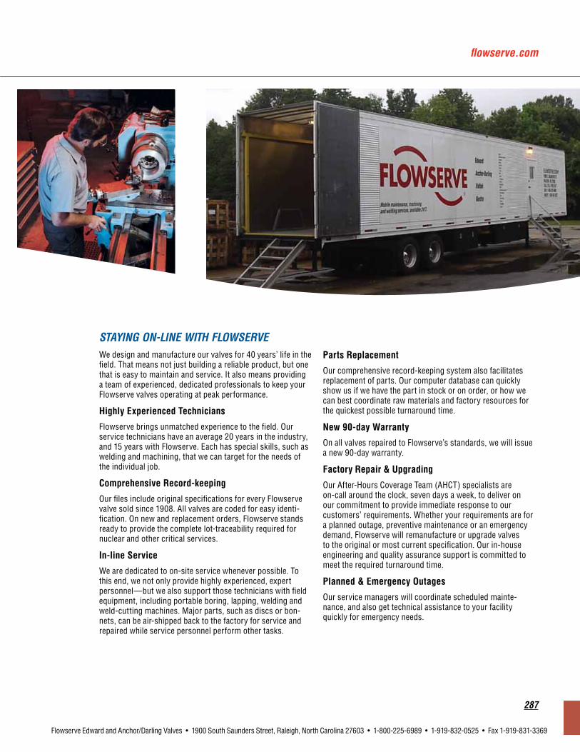
flowserve.com
287
Flowserve Edward and Anchor/Darling Valves • 1900 South Saunders Street, Raleigh, North Carolina 27603 • 1-800-225-6989 • 1-919-832-0525 • Fax 1-919-831-3369
We design and manufacture our valves for 40 years’ life in the field. That means not just building a reliable product, but one that is easy to maintain and service. It also means providing a team of experienced, dedicated professionals to keep your Flowserve valves operating at peak performance.
HighlyExperiencedTechnicians
Flowserve brings unmatched experience to the field. Our service technicians have an average 20 years in the industry, and 15 years with Flowserve. Each has special skills, such as welding and machining, that we can target for the needs of the individual job.
ComprehensiveRecord-keeping
Our files include original specifications for every Flowserve valve sold since 1908. All valves are coded for easy identi-fication. On new and replacement orders, Flowserve stands ready to provide the complete lot-traceability required for nuclear and other critical services.
In-lineService
We are dedicated to on-site service whenever possible. To this end, we not only provide highly experienced, expert personnel—but we also support those technicians with field equipment, including portable boring, lapping, welding and weld-cutting machines. Major parts, such as discs or bon-nets, can be air-shipped back to the factory for service and repaired while service personnel perform other tasks.
PartsReplacement
Our comprehensive record-keeping system also facilitates replacement of parts. Our computer database can quickly show us if we have the part in stock or on order, or how we can best coordinate raw materials and factory resources for the quickest possible turnaround time.
New90-dayWarranty
On all valves repaired to Flowserve’s standards, we will issue a new 90-day warranty.
FactoryRepair&Upgrading
Our After-Hours Coverage Team (AHCT) specialists are on-call around the clock, seven days a week, to deliver on our commitment to provide immediate response to our customers’ requirements. Whether your requirements are for a planned outage, preventive maintenance or an emergency demand, Flowserve will remanufacture or upgrade valves to the original or most current specification. Our in-house engineering and quality assurance support is committed to meet the required turnaround time.
Planned&EmergencyOutages
Our service managers will coordinate scheduled mainte-nance, and also get technical assistance to your facility quickly for emergency needs.
STAYING ON-LINE WITH FLOWSERVE
flowserve.com
To find your local Flowserve representative:
For more information about Flowserve Corporation, visit www.flowserve.com or call USA 1 800 225 6989
Flowserve Corporation has established industry leadership in the design and manufacture of its products. When properly selected, this Flowserve product is designed to perform its intended function safely during its useful life. However, the purchaser or user of Flowserve products should be aware that Flowserve products might be used in numerous applications under a wide variety of industrial service conditions. Although Flowserve can (and often does) provide general guidelines, it cannot provide specific data and warnings for all possible applications. The purchaser/user must therefore assume the ultimate responsibility for the proper sizing and selection, installation, operation and maintenance of Flowserve products. The purchaser/user should read and understand the Installation Operation Maintenance (IOM) instructions included with the product, and train its employees and contractors in the safe use of Flowserve products in connection with the specific application.
While the information and specifications contained in this literature are believed to be accurate, they are supplied for informative purposes only and should not be considered certified or as a guarantee of satisfactory results by reliance thereon. Nothing contained herein is to be construed as a warranty or guarantee, express or implied, regarding any matter with respect to this product. Because Flowserve is continually improving and upgrading its product design, the specifications, dimensions and information contained herein are subject to change without notice. Should any question arise concerning these provisions, the purchaser/user should contact Flowserve Corporation at any one of its worldwide operations or offices.
© 2012 Flowserve Corporation, Irving, Texas, USA. Flowserve is a registered trademark of Flowserve Corporation.
UnitedStatesFlowserve CorporationFlow Control1900 South Saunders StreetRaleigh, NC 27603Telephone: +1 919 832 0525Telefax: +1 919 831 3369
FCD EVENCT0004-02 Printed in USA.
Related Documents