MAN061 Rev Date 5/22/2007 ENVIROMUX-MINI Mini Server Environment Monitoring System Installation and Operation Manual Firmware Version 1.28 ENVIROMUX ® Series NETWORK TECHNOLOGIES INCORPORATED Tel:330-562-7070 Fax:330-562-1999 1275 Danner Dr Aurora, OH 44202 www.networktechinc.com NTI R

Welcome message from author
This document is posted to help you gain knowledge. Please leave a comment to let me know what you think about it! Share it to your friends and learn new things together.
Transcript

MAN061 Rev Date 5/22/2007
ENVIROMUX-MINI Mini Server Environment Monitoring System
Installation and Operation Manual Firmware Version 1.28
ENVIROMUX® Series
NETWORKTECHNOLOGIESINCORPORATED
Tel:330-562-7070Fax:330-562-1999
1275 Danner DrAurora, OH 44202
www.networktechinc.comNTI R
i
TRADEMARK ENVIROMUX is a registered trademark of Network Technologies Inc in the U.S. and other countries. COPYRIGHT Copyright © 2005-2007 by Network Technologies Inc. All rights reserved. No part of this publication may be reproduced, stored in a retrieval system, or transmitted, in any form or by any means, electronic, mechanical, photocopying, recording, or otherwise, without the prior written consent of Network Technologies Inc, 1275 Danner Drive, Aurora, Ohio 44202.
CHANGES The material in this guide is for information only and is subject to change without notice. Network Technologies Inc reserves the right to make changes in the product design without reservation and without notification to its users. FIRMWARE VERSION Firmware Version 1.28 Shielded CAT 5,5e, or 6 cable must be used to connect to the ETHERNET and RS232 ports in order to meet CE emission requirements. Shielded cable must be used to connect to the DRY CONTACT ports in order to meet CE emission requirements. CE Statement We, Network Technologies Inc, declare under our sole responsibility that the ENVIROMUX-MINI is in conformity with European Standard EN55022. UL Listing/CUL File E238791 This information technology equipment is UL-Listed and CUL Listed or CSA-Certified for the uses described in this manual. Federal Communications Commission Radio Frequency Interference Statement This device complies with Part 15 of the FCC rules. Operation is subject to the following two conditions: (1) This device may not cause harmful interference and (2) this device must accept any interference received, including interference that might cause undesired operation. This device complies with Part 15 of the FCC rules. This equipment has been tested and found to comply with the limits for a Class A digital device, pursuant to Part 15 of the FCC rules. These limits are designed to provide reasonable protection against harmful interference when the equipment is operated in a commercial environment. Warning: This equipment generates, uses and can radiate radio frequency energy, and, if not installed and used in accordance with the instruction manual, may cause harmful interference to radio communications. Typographic Conventions The following table describes the typographic changes used in this manual.
Typeface Meaning Example AAaaBBaaCCcc123 The names of commands, files, and directories
On-screen computer output Download the x.hex file C:> eZ80L92>
AAaaBBaaCCcc123 What you type, contrasted with on-screen computer output eZ80L92> C AAaaBBaaCCcc123 Names of menu choices in the operating system Transfer
Send File

ii
TABLE OF CONTENTS
Introduction...................................................................................................................................................................... 1 Materials .......................................................................................................................................................................... 1 Supported Web Browsers ............................................................................................................................................... 3 Features and Functions................................................................................................................................................... 3 Installation ....................................................................................................................................................................... 4
Mount the Unit ............................................................................................................................................................. 4 Connect Sensors and Power....................................................................................................................................... 4
Overview - Use And Operation........................................................................................................................................ 6 Sensors..................................................................................................................................................................... 6 IP Assignment........................................................................................................................................................... 6 User Management .................................................................................................................................................... 6 Alerts......................................................................................................................................................................... 6 Data Logging............................................................................................................................................................. 7 Email ......................................................................................................................................................................... 7 SNMP........................................................................................................................................................................ 7 Syslog ....................................................................................................................................................................... 7 Power-on/Reset Operation ....................................................................................................................................... 7 Out-of-Box Operation................................................................................................................................................ 7
Device Discovery Tool..................................................................................................................................................... 8 Use and Operation via Web Interface ............................................................................................................................. 9
Log In ........................................................................................................................................................................... 9 General Settings ........................................................................................................................................................ 10 Network Settings........................................................................................................................................................ 11 Email Configuration ................................................................................................................................................... 12 Date and Time ........................................................................................................................................................... 13 User Management ..................................................................................................................................................... 14
User Privileges........................................................................................................................................................ 14 Guest User.............................................................................................................................................................. 15
Sensor Management ................................................................................................................................................. 16 Name ...................................................................................................................................................................... 17 Thresholds .............................................................................................................................................................. 17 Alert Timing............................................................................................................................................................. 17 Alert Methods.......................................................................................................................................................... 17
Email.................................................................................................................................................................... 17 SNMP .................................................................................................................................................................. 17 Syslog .................................................................................................................................................................. 17
System Log................................................................................................................................................................ 18 View the Local Log.................................................................................................................................................. 18 Events to Log.......................................................................................................................................................... 19 Log Methods ........................................................................................................................................................... 19 Overflow Actions..................................................................................................................................................... 20
SNMP MIB Configuration........................................................................................................................................... 20 PC-To-ENVIROMUX-MINI Crossover Cable ................................................................................................................ 21 Restore Defaults............................................................................................................................................................ 21 Update the Firmware..................................................................................................................................................... 22
To Update the Firmware ......................................................................................................................................... 22 To Change the MAC address ................................................................................................................................. 22
Specifications ................................................................................................................................................................ 23 TroubleShooting ............................................................................................................................................................ 24 Index.............................................................................................................................................................................. 25 Warranty Information..................................................................................................................................................... 25

iii
TABLE OF FIGURES Figure 1- Rotate the tabs for Zero-RU mounting................................................................................................................................4 Figure 2- Connect sensors to ENVIROMUX-MINI and mount with a cable tie...................................................................................4 Figure 3- Secure liquid detection sensor with tape ............................................................................................................................5 Figure 4- Terminal block for dry-contact sensors...............................................................................................................................5 Figure 5- Connect ENVIROMUX-MINI to the Ethernet ......................................................................................................................5 Figure 6- Connect the AC adapter and power-up ..............................................................................................................................5 Figure 7- Device Discovery Tool page...............................................................................................................................................8 Figure 8- Login prompt to access web interface ................................................................................................................................9 Figure 9- Administrator's Status Summary page and menu...............................................................................................................9 Figure 10- General menu for administrative settings .......................................................................................................................10 Figure 11- Network configuration page (defaults shown).................................................................................................................11 Figure 12- HyperTerminal view of bootup information .....................................................................................................................12 Figure 13- Email configuration page ................................................................................................................................................12 Figure 14- Date and Time configuration page..................................................................................................................................13 Figure 15- User Management for controlling user access................................................................................................................14 Figure 16- Status Summary and menu for Guest users...................................................................................................................15 Figure 17- Specific sensor information.............................................................................................................................................16 Figure 18- Sensor alert record configuration....................................................................................................................................16 Figure 19- View the local event log..................................................................................................................................................18 Figure 20- Configure events to be logged........................................................................................................................................19 Figure 21- Define log methods.........................................................................................................................................................20 Figure 22- Overflow actions-when the log is too large .....................................................................................................................20 Figure 23- Location of the Restore button........................................................................................................................................21

NTI MINI SERVER ENVIRONMENT MONITORING SYSTEM
1
INTRODUCTION The ENVIROMUX-MINI Server Environment Monitoring System is designed to monitor, from a remote location, the critical environmental conditions in cabinets and rooms containing servers, hubs, switches and other network components. Specifically, the ENVIROMUX-MINI will monitor temperature, humidity, and detect the presence of water on a flat surface (such as the floor). The unit also has four sets of terminal block pairs for the connection of contact-closure sensors. Remote monitoring is provided via a 10BaseT Ethernet web interface. The input data is filtered, collected, analyzed and processed to allow the user to configure it to meet individual requirements. The user is able to specify parameters for all monitored signals. When a sensor exceeds the configured threshold, the unit will signal an alert. Alert methods include email, SNMP traps (MIBs), web-page alerts, and a visual indicator (red LED). Features and Applications
Monitor and manage server room environmental conditions over IP. Monitors and operates at temperatures from 32°F to 104°F (0ºC and 40ºC) and 20% to 80% relative humidity. Optional support for harsh high temperature environments (See below) Sensors supported:
• 2 temperature/humidity sensors • 1 liquid detection sensor • 4 open-collector input devices
Operates and configures via HTTP web page. 4 remote users can access the system simultaneously. Supports SMTP protocol Supports SNMP V1 MIB Sensor alerts and log messages are sent using email and SNMP traps when any monitored environmental condition
exceeds a user-specified range. Sensor alerts, end of alerts, and log-ins are posted in message log, which is accessible through web interface. SNMP trap messages can be imported into Microsoft Excel Mounting tabs included for Zero-RU mounting Flash upgradeable firmware. Use in data centers, co-lo sites, web hosting facilities, telecom switching sites, POP sites, server closets, or any
unmanned area that needs to be monitored.
Option: ENVIROMUX-MINI-IND- Industrial Server Environment Monitoring System for high temperature environments. ENVIROMUX-MINI-IND will monitor and operate in temperatures from 32°F to 167°F (0ºC to 75ºC). Note: Humidity sensors will only function properly at temperatures from 32° F to 104° F when used with ENVIROMUX-MINI-IND.
MATERIALS Materials Included with this kit:
NTI ENVIROMUX-MINI 1- 120VAC or 240VAC at 50 or 60Hz-5VDC/2.0A AC Adapter 2-10-32 x 3/4" pan head screws and 10-32 cage nuts (server cabinet mounting hardware) 1- DB9 Female-to-RJ45 Female adapter 1- DB25 Female-to-RJ45 Female adapter 1- 5 foot RJ45-to-RJ45 CAT5 patch cable CD containing a pdf of this manual, pdf of a Quick Installation Guide, Discovery Tool, and an SNMP MIB file Printed Quick Installation Guide 2- Mounting tabs for Zero-RU mounting (pre-assembled to back of ENVIROMUX-MINI- see page 4)
Additional materials may need to be ordered, depending upon the configuration: CAT5/5e/6 unshielded twisted-pair cable(s) terminated with RJ45 connectors wired straight thru- pin 1 to pin 1, etc.
Available DC-DC Converter- to install the ENVIROMUX-MINI in a Telecom environment. Order PWR-48V-5V1A.
* Converter accepts 36~72VDC (48VDC nominal), positive or negative polarity. * Outputs +5VDC \1.0A maximum * 3-pole screw terminal for connecting 48V input * 2.1x5.5mm male DC power jack and a 3 foot 2.1 x 5.5mm female-to-female plug power cable is included * Dimensions WxDxH (in.): 1.8x2.1x1

NTI MINI SERVER ENVIRONMENT MONITORING SYSTEM
2
Available Sensors (Sold separately) : FYI: Temperature and Humidity Sensors are available in 3, 7, 10 and 25 foot cable lengths.
ENVIROMUX-T-xx Temperature Sensor for ENVIROMUX-MINI ENVIROMUX-T-IND-xx Temperature Sensor for ENVIROMUX-MIN-IND
* Applications from 32°F to 104°F (0ºC to 40ºC) for the ENVIROMUX-T-xx. * Applications from 32°F to 167°F (0ºC to 75ºC) for the ENVIROMUX-T-IND-xx. * High resistance to external influences on the cable due to digital output signal. * Accurate to within ±1.35°F (±0.75ºC). * Includes mounting hardware.
ENVIROMUX-RH-xx Humidity Sensor (EXTENDED RANGE SENSOR NOT AVAILABLE FOR ENVIROMUX-MINI-IND) * Applications from 20% to 80% relative humidity at temperatures between 0ºC and 40ºC. * High resistance to external influences on the cable due to digital output signal. * Accurate to within ±5% relative humidity. * Includes mounting hardware.
ENVIROMUX-TRH-xx Temperature/Humidity Combination Sensor (EXTENDED RANGE SENSOR NOT AVAILABLE FOR ENVIROMUX-MINI-IND) * Applications from 32°F to 104°F (0ºC and 40ºC) and 20% to 80% relative humidity. * High resistance to external influences on the cable due to digital output signal. * Accurate to within ±1.35°F (±0.75ºC) and ±5% relative humidity. * Includes mounting hardware.
ENVIROMUX-LD-xx Liquid Detection Sensor * For warning of flooding.
* Applications from 32°F to 167°F (0ºC to 75ºC) * 100% waterproof electronics.
* Detects any conductive liquid.
ENVIROMUX-M-DCS Door Contact Sensor * Monitors access with a magnetic bridge sensor * Screw terminals for 2-wire interface * Wide actuating gap - approximately 1" * Normally closed circuit connection * Dimensions WxDxH (in.)- 0.5x0.5x2 (Switch), 0.5x0.5x2 (Magnet)
ENVIROMUX-TDS Tamper Switch
* Sends activation signal when released * Normally closed contact when depressed * 2-wire interface * Dimensions: 0.8 inner diameter, 0.9 outer diameter, 2.9 height
ENVIROMUX-EBS Emergency/Panic Button * Sends activation signal when button is pressed * For Normally closed or open circuit connections * 2-wire screw-terminal interface
* Dimensions WxDxH: 0.4x0.9x3
ENVIROMUX-2W-xx Sensor Cables * 2-wire sensor cable * Used to connect dry contact sensors to the ENVIROMUX-MINI * Available lengths (ft): 3/6/10/25/50/100 There are more sensors to be added. See our webpage for the latest available.
Contact your nearest NTI distributor or NTI directly for all of your cable needs at 800-RGB-TECH (800-742-8324) in US & Canada or 330-562-7070 (Worldwide) or at our website at http://www.networktechinc.com and we will be happy to be of assistance. Shielded CAT 5,5e, or 6 cable must be used to connect to the ETHERNET and RS232 ports in order to meet CE emission requirements. Shielded cable must be used to connect to the DRY CONTACT ports in order to meet CE emission requirements.

NTI MINI SERVER ENVIRONMENT MONITORING SYSTEM
3
SUPPORTED WEB BROWSERS
Most modern web browsers should be supported. The following browsers have been tested: • Microsoft Internet Explorer 6.0 or higher • Netscape 7.0 or higher • Mozilla FireFox 0.9.2 or higher
FEATURES AND FUNCTIONS 1. 5V 2.0A- Jack for connection of power supply 2. TEMPERATURE/HUMIDITY-RJ45 female connectors- for connection of optional ENVIROMUX-T, ENVIROMUX-RH, or
ENVIROMUX-TRH sensors (The right port is "#1", the left port is "#2" as listed in the Summary Page on Page 9.) 3. WATER- terminals for connection of ENVIROMUX-LD liquid detection sensor 4. CONTACTS 1-4- terminals for connecting dry-contact sensors 5. PWR- power indicator light- illuminates to indicate proper power to the unit and normal operation (i.e. indicates that there are
no alerts) 6. FAULT- fault indicator light- illuminates to indicate a fault condition has been reached at one or more sensors 7. RS232- RJ45 female- for connection of a PC for firmware upgrades 8. ETHERNET- RJ45 female- for connection to an Ethernet for remote multi-user control and monitoring

NTI MINI SERVER ENVIRONMENT MONITORING SYSTEM
4
INSTALLATION
Mount the Unit The ENVIROMUX-MINI can either be placed on a solid surface, mounted to a wall, or mounted to an accessible surface within rack (Zero-RU). To mount to a wall or other surface, first remove the screws holding the mounting tabs to the rear of the box. Rotate the tabs such that they extend from the back of the box, and attach the tabs with the screws removed. Now the ENVIROMUX-MINI can be secured to any convenient surface. Two 10-32 x 3/4" machine screws and cage nuts have been provided to assist mounting within a sever cabinet. Use appropriate hardware (not supplied) when mounting to a wall.
Figure 1- Rotate the tabs for Zero-RU mounting
Connect Sensors and Power 1. Connect the desired sensors (ENVIROMUX-T, RH, or TRH- sold separately) to the available ports on the ENVIROMUX-MINI. Plug the RJ45 connectors to either of the two ports marked "TEMPERATURE/HUMIDITY". The ENVIROMUX-T, RH, or TRH sensors can be secured anywhere that the temperature and/or relative humidity need to be sensed. Secure the cable tie base (provided with each sensor) to a surface close to where the temperature and/or humidity needs to be monitored, and secure the sensor to the cable tie base with a cable tie. Make sure the surface to which the cable tie base will be applied is clean or the adhesive on the cable tie base will not adhere to it. (see Fig. 2). Note: Mounting the sensor in the path of a fan or on a heated surface may affect the accuracy of the sensor’s readings. Note: For best results, use the ENVIROMUX-T-IND with model ENVIROMUX-MINI-IND (see Sensors, pg 6).
Figure 2- Connect sensors to ENVIROMUX-MINI and mount with a cable tie
Mount sensor where temperature and/orhumidity monitoring is needed.
ENVIROMUX-T / RH / TRH
RS232 ETHERNET FAULT
SENSE SENSEWATER CONTACTS
+5V1 2 3 4
+5V +5V +5V
ENVIROMUX TM
NTI R
Network Technologies Inc
TEMPERATURE / HUMIDITY
Front View of ENVIROMUX-MINI
5V2.0A
AREA ALERT TMPWR
ENVIROMUX-T-INDHigh Temperature Sensor
RJ45-maleconnector Mount sensor where
high temperature monitoring is needed.
(For ENVIROMUX-MINI-IND)

NTI MINI SERVER ENVIRONMENT MONITORING SYSTEM
5
2. Connect the optional liquid detection sensor (ENVIROMUX-LD- sold separately) to the terminals marked "WATER". The twisted orange sensing cable should be placed flat on the surface (usually the floor) where liquid detection is desired. If tape is required to hold the sensor in place, be sure to only apply tape to the ends, exposing as much of the sensor as possible. At least 5/8" of the sensor must be exposed for it to function. (See Fig. 3)
Figure 3- Secure liquid detection sensor with tape 3. Up to four dry-contact sensors can also be connected . Sensors with 16-26 AWG connection wires, that operate on 5V at 10mA maximum current may be used. A contact resistance of 10kΩ or less will be interpreted by the ENVIROMUX-MINI as a closed contact. To install the dry-contact sensor(s):
A. Attach the positive lead to a terminal corresponding to a "+5V" marking on the ENVIROMUX-MINI and the ground lead to the next terminal to the right that will correspond to a marking on the ENVIROMUX-MINI. Tighten the set screw above each contact. Terminal sets are numbered 1-4. B. Mount the sensors as desired.
Figure 4- Terminal block for dry-contact sensors Note: The terminal block is removable for easy sensor wire attachment if needed. 4. Connect a CAT5 patch cable (RJ45 connectors on each end wired pin 1 to pin 1, pin 2 to pin 2 etc) from the local Ethernet
network connection to the connector on the ENVIROMUX-MINI marked "ETHERNET".
Figure 5- Connect ENVIROMUX-MINI to the Ethernet 5. Connect the AC adapter to the connection marked "PWR" on the ENVIROMUX-MINI and plug it into an outlet.
Figure 6- Connect the AC adapter and power-up 6. Use the NTI Discovery Tool (page 8) to configure network settings.
+5V1
Example: Device with potential-freebreak/make contact relay (i.e. door switch)
For direct connection from a PC to the ENVIROMUX-MINI, use a crossover cable. See page 21 for crossover cable pinout.
! ! "
# $
% & ' (
# $ # $ # $
) ( $
" & ' & ! * ! + !
" " " "
, ! ! ! "
# $
% & ' (
# $ # $ # $
! - ! . * ! /
+ 0
$ & 1 2
! ! - ,
$
- !
" & ' & ! * ! + !
" " " "
, ! ! ! "
# $
% & ' (
# $ # $ # $
! - ! . * ! /
+ 0
$ & 1 2
! ! - ,
3
4 5 6
4 5 6
NTI MINI SERVER ENVIRONMENT MONITORING SYSTEM
6
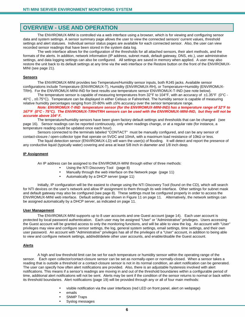
OVERVIEW - USE AND OPERATION The ENVIROMUX-MINI is controlled via a web interface using a browser, which is for viewing and configuring sensor
data and system settings. A sensor summary page allows the user to view the connected sensors’ current values, threshold settings and alert statuses. Individual sensor status pages are available for each connected sensor. Also, the user can view recorded sensor readings that have been stored in the system data log.
The web interface allows for the configuration of the thresholds for all attached sensors, their alert methods, and the formats of the alerts. In addition, network information (IP address, subnet mask, default gateway, DNS, etc.), user administrative settings, and data logging settings can also be configured. All settings are saved in memory when applied. A user may also restore the unit back to its default settings at any time via the web interface or the Restore button on the front of the ENVIROMUX-MINI (see page 21).
Sensors The ENVIROMUX-MINI provides two Temperature/Humidity sensor inputs, both RJ45 jacks. Available sensor
configurations include Temperature (ENVIROMUX-T), Humidity (ENVIROMUX-RH), or Temperature+Humidity (ENVIROMUX-TRH). For the ENVIROMUX-MINI-IND for best results use temperature sensor ENVIROMUX-T-IND (see note below).
The temperature sensor is capable of measuring temperatures from 32°F to 104°F, with an accuracy of ±1.35°F (0°C - 40°C , ±0.75°C). Temperature can be displayed in either Celsius or Fahrenheit. The humidity sensor is capable of measuring relative humidity percentages ranging from 20-80% with ±5% accuracy over the sensor temperature range.
Note: ENVIROMUX-T-IND temperature sensor (for the ENVIROMUX-MINI-IND) has a temperature range of 32°F to 167°F (0°C - 75°C). The ENVIROMUX-T/RH/TRH sensors can be used with the ENVIROMUX-MINI-IND, but they will not be accurate above 104º F.
The temperature/humidity sensors have been given factory default settings and thresholds that can be changed (see page 16). Sensor readings can be reported continuously, only when readings change, or at a regular rate (for instance, a temperature reading could be updated once each hour).
Sensors connected to the terminals labeled "CONTACT" must be manually configured, and can be any sensor of contact-closure / open-collector type that operate on 5VDC and 10mA, with a maximum load resistance of 10kΩ or less.
The liquid detection sensor (ENVIROMUX-LD) will warn the user(s) of flooding. It will detect and report the presence of any conductive liquid (typically water) covering and area at least 5/8 inch in diameter and 1/8 inch deep.
IP Assignment An IP address can be assigned to the ENVIROMUX-MINI through either of three methods:
• Using the NTI Discovery Tool (page 8) • Manually through the web interface on the Network page (page 11) • Automatically by a DHCP server (page 11)
Initially, IP configuration will be the easiest to change using the NTI Discovery Tool (found on the CD), which will search
for NTI devices on the user’s network and allow IP assignment to them through its web interface. Other settings for subnet mask and default gateway may also be configured (see page 8). These settings must be configured properly in order to access the ENVIROMUX-MINI web interface. Default settings are shown in Figure 11 on page 11. Alternatively, the network settings can be assigned automatically by a DHCP server, as indicated on page 11.
User Management The ENVIROMUX-MINI supports up to 8 user accounts and one Guest account (page 14). Each user account is
protected by local password authentication. Each user may be assigned "User" or "Administrative" privileges. Users accessing the Guest account will be granted access to only the monitoring functions, and will be able to view the log. An account with "User" privileges may view and configure sensor settings, the log, general system settings, email settings, time settings, and their own user password. An account with "Administrative" privileges has all of the privileges of a "User" account, in addition to being able to view and configure network settings, add/edit/delete other user accounts, and enable/disable the Guest account.
Alerts
A high and low threshold limit can be set for each temperature or humidity sensor within the operating range of the sensor. Each open collector/contact-closure sensor can be set as normally-open or normally-closed. When a sensor takes a reading that is outside a threshold or a contact-closure sensor is not in its normal condition, an alert notification can be generated. The user can specify how often alert notifications are provided. Also, there is an adjustable hysteresis involved with alert notifications. This means if a sensor’s readings are moving in and out of the threshold boundaries within a configurable period of time, additional alert notifications will not be sent. Alerts may be sent if the condition of the sensor returns to normal or back within its threshold boundaries. Alert notifications (page 19) will be provided through any or all of four main methods:
• visible notification via the user interfaces (red LED on front panel, alert on webpage) • emails • SNMP Traps • Syslog messages

NTI MINI SERVER ENVIRONMENT MONITORING SYSTEM
7
Data Logging The ENVIROMUX-MINI can log sensor readings, sensor alerts, alert handling, and user logins/logouts. The log can be
viewed at any time through the web interface (page 18). Additionally, as entries are generated, they can be emailed or sent as SNMP traps. Entries can be deleted from the log via the web interface. The maximum size of the data log is 100 entries. The log’s behavior upon reaching this maximum size can be configured, allowing the log to either wrap (overwrite oldest entries), or stop logging. The entire log can be downloaded as a plain text file from the web interface at any time (see "View the Log" on page 18).
Email The ENVIROMUX-MINI can access an outgoing SMTP server to send email. Outgoing mail may contain pre-formatted
alert notifications or data log messages. The user can configure what conditions cause emails to be sent. The ENVIROMUX-MINI’s email address, as well as SMTP server information and the email addresses to which emails are sent, can be configured on the Network page through the web interface (page 11). Up to 3 outgoing email addresses (112 characters maximum including commas) may be configured.
SNMP The ENVIROMUX-MINI can send alerts as SNMP traps (V1) when a sensor enters/leaves alert mode, and for all log
events. Using an SNMP MIB browser, a user can monitor all sensor statuses and system IP settings, as well as configure sensor thresholds, sensor names, and the system name. The destination for SNMP traps can be configured on the Network page (page 11).
Note: The SNMP MIB file (enviromux-mini.mib), for use with an SNMP MIB browser, can be found on the manual CD. Click on the link to open the file, then save the file to your hard drive to use with the SNMP MIB browser.
Syslog The ENVIROMUX-MINI can send alerts as SYSLOG messages when a sensor enters/leaves alert mode, and for all log events. The destination for SYSLOG can be configured on the Log Methods page (page 20).
Power-on/Reset Operation On power-up, after going through its boot sequence, the ENVIROMUX-MINI will launch the monitoring application, load
any stored configuration values, and immediately identify and begin taking readings from any connected sensors. Alerts will be reported using the configured alert methods, and data will be logged using the stored preferences. A user can log in at any time after the system has launched the monitoring application (approximately 5 seconds after power is applied) to view and configure properties of the system and its sensors.
Note: It is normal for the red LED (Fault Indicator) to be illuminated for a few seconds upon startup.
Out-of-Box Operation The operation of the unit directly out of the box is nearly identical to the Power-on/Reset operation. However, information about the unit will only be able to be monitored and controlled once valid network settings are assigned to the device (see IP Assignment on page 6). The network settings must be compatible with the physical network to which the ENVIROMUX-MINI is attached. Also, alert notifications will only be able to be viewed through the user interfaces (LED, web page). Email and SNMP alert notifications must be configured within the web interface (page 11) before these methods can be used. Once these configurations are made, they will be saved in the unit, even if the ENVIROMUX-MINI is powered-OFF.

NTI MINI SERVER ENVIRONMENT MONITORING SYSTEM
8
DEVICE DISCOVERY TOOL In order to easily locate the ENVIROMUX-MINI on a network, and change the IP settings, the NTI Device Discovery Tool may be used. A link to the Discovery Tool is provided on the web page that appears when the instruction manual CD is inserted into the computer's CD ROM drive. Click on the link or browse the CD and click on the file discover.html . This will open a browser and display the Device Discovery Tool page. Note: The Discovery Tool requires the Java Runtime Environment to operate. A link to the web page from which it can be downloaded and installed is provided on the CD. Note: The computer using the Discovery Tool and the ENVIROMUX-MINI must be connected to the same physical network in order for the Device Discovery Tool to work.
Figure 7- Device Discovery Tool page Use the Device Discovery Tool to display all NTI devices on your network, along with their network settings. Follow the instructions on the Device Discovery Tool page to use the tool and to change the device settings if so desired.
FYI: The "Blink LED" button will blink the green "PWR" LED on the ENVIROMUX to identify which unit is associated with the settings shown.
Note: If the IP address is set to be obtained automatically from a DHCP server (see page 11, Fig. 11), then the IP address will not be able to be manually changed. If an attempt is made, the DHCP server will automatically change it back to the automatically assigned address.

NTI MINI SERVER ENVIRONMENT MONITORING SYSTEM
9
USE AND OPERATION VIA WEB INTERFACE A user may monitor and configure the settings of any device connected to the ENVIROMUX-MINI using the Web Interface via any web browser (see page 2 for supported web 3. To enable the Web Interface, connect the ENVIROMUX-MINI to the Ethernet (page 5). Use the Discovery Tool (page 8) to setup the network settings. Then, to access the web interface controls, the user must log in.
Log In To access the web interface, type the current IP address into the address bar of the web browser. (The default IP address is shown below): Note: If the HTTP Server Port number is changed (page 11) from port 80 (default), then the port number will need to be added to the IP address (i.e. if the port number is changed to 95, then the IP address would be http://192.168.1.21:95) A log in prompt requiring a username and password will appear: Username = Administrator (uppercase letter for "A" only) Password = admin (lower case letters only) Note: usernames and passwords are case sensitive
Figure 8- Login prompt to access web interface With a successful log in, as screen similar to the following will appear:
Figure 9- Administrator's Status Summary page and menu
http://192.168.1.21

NTI MINI SERVER ENVIRONMENT MONITORING SYSTEM
10
The initial web interface page includes a status summary showing the present name, type, value, and status of each sensor attached to the ENVIROMUX-MINI. It also includes a menu to the left of the screen from which the administrator can select pages that will allow them to:
• change the general settings of the ENVIROMUX-MINI • configure network settings • perform user management to control who has access to the sensor information • configure each of the sensors • configure the ENVIROMUX-MINI for how it will report sensor alerts and to whom • configure sensor event log recording
General Settings
Figure 10- General menu for administrative settings From the General menu under ADMINISTRATION, the user can make changes as follows: • Node Name- change the name of the ENVIROMUX-MINI. The Node Name will appear in SNMP trap
messages to enable the user to identify the source of the alert • Node Location- assign a reference location (where the ENVIROMUX-MINI is located). The Node Location will
also appear in SNMP trap messages to aid in user identification of the source of the alert. • Update sensor status
pages- configure how often the sensors will have data updated on the summary page
• Restore- restore the ENVIROMUX-MINI to all factory default settings including usernames, passwords, and all network and sensor settings.
• Reboot- reboot the ENVIROMUX-MINI- refreshing settings and communications (this does not restore default settings)
Press Apply if any changes are made above to the fields or the changes will not be saved upon leaving this page. Note: If the Restore or Reboot buttons are pressed, the ENVIROMUX-MINI will erase the system logs. It is recommended that the logs be downloaded if they need to be saved before using the Restore or Reboot buttons (see page 18 to download System Logs). If the TIMEP server is not configured (page 13), the manually set time will be incorrect after using these buttons.
FYI: If a user tries to log in with a username already logged in at another IP address, the user will be presented with "The user <username> is already logged in at IP address <IP address>. If you continue, <username> will be logged out. Continue?". Select the "Yes" or "No" button. Selecting "Yes" will log out the first user. Selecting "No" will take the user back to the log in page (or summary page if Guest is enabled (page 14)).
NTI MINI SERVER ENVIRONMENT MONITORING SYSTEM
11
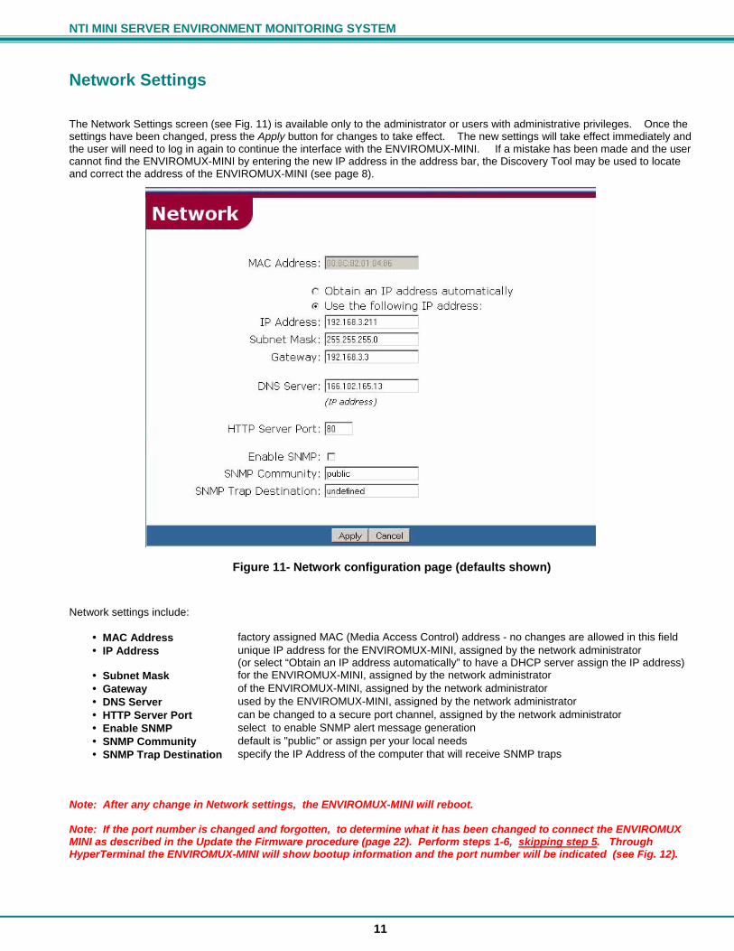
Network Settings The Network Settings screen (see Fig. 11) is available only to the administrator or users with administrative privileges. Once the settings have been changed, press the Apply button for changes to take effect. The new settings will take effect immediately and the user will need to log in again to continue the interface with the ENVIROMUX-MINI. If a mistake has been made and the user cannot find the ENVIROMUX-MINI by entering the new IP address in the address bar, the Discovery Tool may be used to locate and correct the address of the ENVIROMUX-MINI (see page 8).
Figure 11- Network configuration page (defaults shown) Network settings include:
• MAC Address factory assigned MAC (Media Access Control) address - no changes are allowed in this field • IP Address unique IP address for the ENVIROMUX-MINI, assigned by the network administrator
(or select “Obtain an IP address automatically” to have a DHCP server assign the IP address) • Subnet Mask for the ENVIROMUX-MINI, assigned by the network administrator • Gateway of the ENVIROMUX-MINI, assigned by the network administrator • DNS Server used by the ENVIROMUX-MINI, assigned by the network administrator • HTTP Server Port can be changed to a secure port channel, assigned by the network administrator • Enable SNMP select to enable SNMP alert message generation • SNMP Community default is "public" or assign per your local needs • SNMP Trap Destination specify the IP Address of the computer that will receive SNMP traps
Note: After any change in Network settings, the ENVIROMUX-MINI will reboot. Note: If the port number is changed and forgotten, to determine what it has been changed to connect the ENVIROMUX MINI as described in the Update the Firmware procedure (page 22). Perform steps 1-6, skipping step 5. Through HyperTerminal the ENVIROMUX-MINI will show bootup information and the port number will be indicated (see Fig. 12).

NTI MINI SERVER ENVIRONMENT MONITORING SYSTEM
12
Figure 12- HyperTerminal view of bootup information
Email Configuration
Figure 13- Email configuration page The Email Page allows users to configure the necessary settings that enable the ENVIROMUX-MINI to send emails via an SMTP server. It requires the following settings: • ENVIROMUX-MINI Email Address- Defines the content of the "From" field in the email messages sent by ENVIROMUX-
MINI.
Note: Some SMTP servers may not accept invalid email addresses and may block some domain names. Be sure that the address is accepted by the SMTP server
• SMTP Server- Defines the outgoing SMTP server by its DNS name or numeric IP address. • Notify addresses- Defines the email addresses of recipient(s). Addresses (up to 3) must be separated by comma. A
maximum of 112 characters (including commas) is accepted in this field.
Note: Improper configuration of these fields may temporarily cause the ENVIROMUX-MINI to stop working. To troubleshoot email configuration problems, check for one or more of the following:
• The indicated SMTP server name is incorrect. • The unit cannot reach the DNS server and cannot look up the numeric IP. • The DNS Server is entered incorrectly in the Network Settings Page. • The SMTP server does not accept the ENVIROMUX-MINI Email Address. • All values are entered correctly, but the unit cannot reach the SMTP server for network routing reasons.
IE: In the SMTP Server field, smtp.mydomain.com_ the extra space at the end of the address will cause a failure.
Note: The ENVIROMUX-MINI will not work on a network whose SMTP server requires password authentication. The ENVIROMUX-MINI is not designed to submit a password when sending alerts via email.
Port #

NTI MINI SERVER ENVIRONMENT MONITORING SYSTEM
13
Date and Time
Figure 14- Date and Time configuration page The Date and Time page in the ADMINISTRATION menu enables the administrator to either manually set the date and time or to have the ENVIROMUX-MINI synchronize with a TIMEP server. If a TIMEP server is specified, the ENVIROMUX-MINI will synchronize with the TIMEP server every 10 minutes. The format in which the date is displayed on other pages can be configured with the Format box. Note: If a TIMEP server is not specified, then the user will need to manually update the date and time any time the ENVIROMUX-MINI loses power. • Current Date and Time- to change the time zone used for the unit, select the desired time zone. In order to have the time
change in accordance with the new Daylight Saving Time rules (passed in 2005), a checkmark must be placed in the block “Automatically adjust clock for daylight saving changes”
• Synchronize with TIMEP Server- used to specify a TIMEP server with which to synchronize the system time. Select the radio button and enter either the domain name or IP address of the desired time server
• Change Date/Time Manually- to manually change the date and/or time, select the radio button and enter the desired date and/or time into the "Date" and "Time" boxes
When entering the date manually, be sure to specify it in the format chosen. Similarly, when entering the time manually, be sure to enter it in the format (hh:mm:ss). where HH is a two digit hour, MM is a two digit minute, and SS is a two digit second.
• Options- the choices in the "Options" section operate as follows when the date and/or time is changed:
• Do not change sensor records – log times and sensor record times will not be adjusted to the new times (default)
• Reset sensor records – sensor records will be reset and will begin recording from the new time
• Adjust sensor records – log times and sensor record times will be adjusted to be relative to the new time
NTI MINI SERVER ENVIRONMENT MONITORING SYSTEM
14
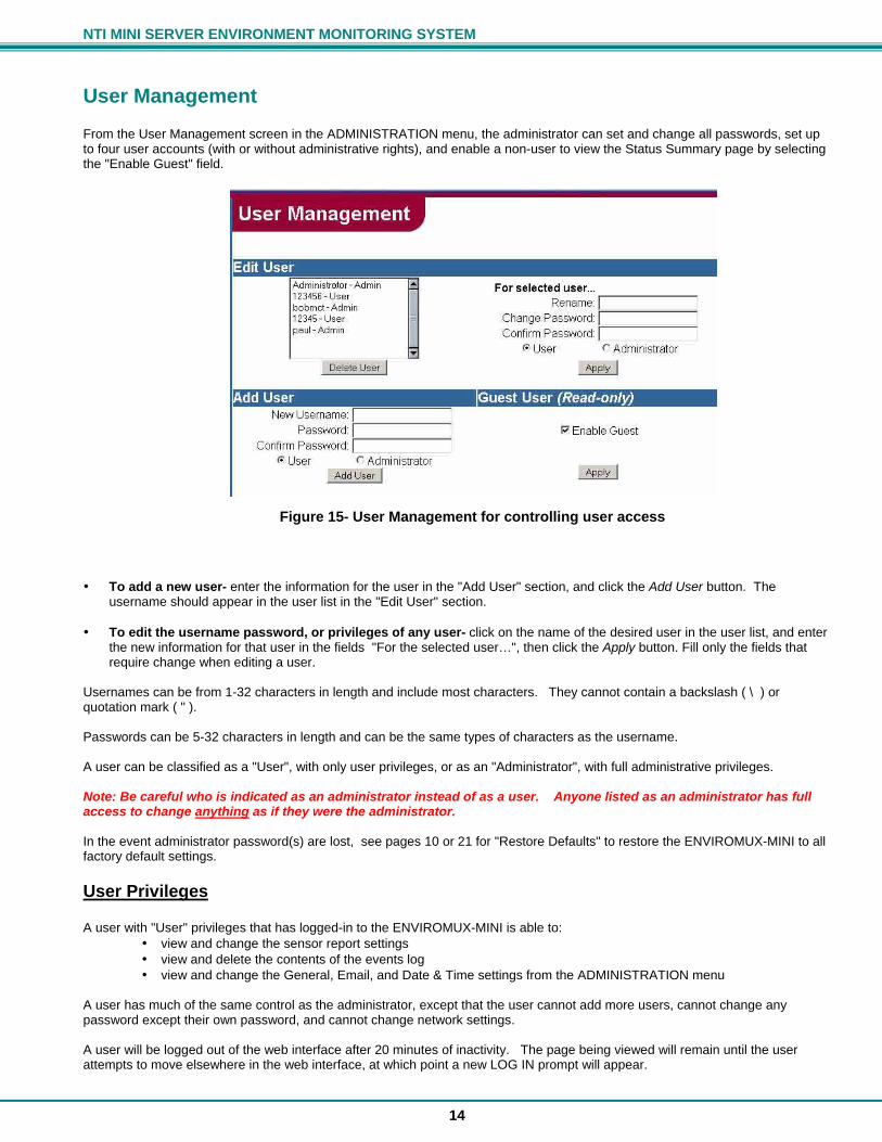
User Management From the User Management screen in the ADMINISTRATION menu, the administrator can set and change all passwords, set up to four user accounts (with or without administrative rights), and enable a non-user to view the Status Summary page by selecting the "Enable Guest" field.
Figure 15- User Management for controlling user access • To add a new user- enter the information for the user in the "Add User" section, and click the Add User button. The
username should appear in the user list in the "Edit User" section. • To edit the username password, or privileges of any user- click on the name of the desired user in the user list, and enter
the new information for that user in the fields "For the selected user…", then click the Apply button. Fill only the fields that require change when editing a user.
Usernames can be from 1-32 characters in length and include most characters. They cannot contain a backslash ( \ ) or quotation mark ( " ). Passwords can be 5-32 characters in length and can be the same types of characters as the username. A user can be classified as a "User", with only user privileges, or as an "Administrator", with full administrative privileges. Note: Be careful who is indicated as an administrator instead of as a user. Anyone listed as an administrator has full access to change anything as if they were the administrator. In the event administrator password(s) are lost, see pages 10 or 21 for "Restore Defaults" to restore the ENVIROMUX-MINI to all factory default settings.
User Privileges A user with "User" privileges that has logged-in to the ENVIROMUX-MINI is able to:
• view and change the sensor report settings • view and delete the contents of the events log • view and change the General, Email, and Date & Time settings from the ADMINISTRATION menu
A user has much of the same control as the administrator, except that the user cannot add more users, cannot change any password except their own password, and cannot change network settings. A user will be logged out of the web interface after 20 minutes of inactivity. The page being viewed will remain until the user attempts to move elsewhere in the web interface, at which point a new LOG IN prompt will appear.

NTI MINI SERVER ENVIRONMENT MONITORING SYSTEM
15
Guest User If the "Enable Guest" field is checked under User Management (pg. 14), then the Summary page (Fig. 16) will be displayed any time the IP address is placed in the browser's address bar.
Figure 16- Status Summary and menu for Guest users On this screen the status of each sensor connected to the ENVIROMUX-MINI is displayed. The guest may view the system log and the status of any sensor. To be able to configure system settings, the user must log in. Click on the "LOG IN" link at the bottom left of the menu. A prompt will appear calling for a username and password to be entered.

NTI MINI SERVER ENVIRONMENT MONITORING SYSTEM
16
Sensor Management In the SUMMARY page each of the sensors attached to the ENVIROMUX-MINI are listed. To view the details of a particular sensor, click on the sensor name in the left column of the screen.
Figure 17- Specific sensor information From here the user can see the threshold settings (in red) and the current reading (in green) of a selected sensor. It also shows the time, date, and measurement taken of the most recent alert, as well as the lowest and highest reading taken by the sensor since it was last powered on(if the sensor is an ENVIROMUX-T / RH / or TRH). If the sensor is a dry-contact type, the contact condition and most recent alert will be indicated. To modify the sensor's attributes (thresholds, alert methods, name, etc.), click on the Configure button. A screen like the following will appear (format may vary depending upon the type of sensor):
Figure 18- Sensor alert record configuration
Suggestion: Once the timing, thresholds, etc. are configured for a sensor, use the Test Alerts feature and press “Simulate Alert” to test the configuration, making sure that events and communications through email , SNMP, and/or Syslog occur as desired. Once this is determined to be satisfactory, press “Clear” to resume normal operation of the sensor.

NTI MINI SERVER ENVIRONMENT MONITORING SYSTEM
17
Name Each sensor can be named. Names can be from 1-32 characters in length and include most characters. They cannot contain a backslash ( \ ) or quotation mark ( " ).
Thresholds The high and low threshold of proper operating temperatures and/or humidity can be configured. If the sensor readings go above or below these settings, an alert can be communicated in a predetermined way (see Alert Methods below). Readings from a dry-contact sensor can be configured to cause an alert to be sent if the contact position changes (open or closed).
Alert Timing The hysteresis of the alert timing can be adjusted. This means that a recurrence of an alert can be delayed in the event the readings from a sensor only fall above or below the threshold levels for the specified period of time. The time period can be set for 1-9999 seconds or minutes. A time period can be set for how long to wait before repeating an alert message after the first message is sent when the sensor remains in an alert condition. The repeated alert can be set to occur from 1-9999 seconds, minutes, or hours. The user can also be notified when the sensor readings have returned to the normal range by selecting the "Notify on return to normal" box for a sensor.
Alert Methods The alert can be configured to notify a user via email, SNMP traps (V1), or Syslog messages. Alerts are also indicated on the FAULT LED on the front of the ENVIROMUX-MINI and in the WEB interface.
Email For the ENVIROMUX-MINI to send an email alert, the Email settings under the ADMINISTRATION menu must be properly configured, as well as the IP address of the DNS server on the Network page from the ADMINISTRATION menu. Put a checkmark in the "Email" box to enable this option. The email addresses chosen for alerts from the Email configuration page will be pre-filled in the text box below the check box. The email addresses may be changed on this page as well. Simply enter the desired email addresses (maximum of 112 characters including commas) and click Apply. Note: If the email addresses are changed on this page, they will also be automatically changed on the Email page.
SNMP For an SNMP trap to be sent, put a checkmark in the "SNMP" box. The SNMP trap destination IP address from the Network configuration page will be pre-filled in the “Notify address” box below. The IP address can also be changed from this page. Simply enter the desired SNMP trap destination IP address and click Apply. Note: If the IP address is changed on this page, it will also be automatically changed on the Network page.
Syslog The ENVIROMUX-MINI can send alerts as SYSLOG messages when a sensor enters/leaves alert mode, and for all log events. For a Syslog message to be sent, put a checkmark in the "Syslog" box. Enter an IP address in the “Notify address” box below and click Apply. A message may also be applied to email and SNMP alerts. The message is optional and may contain up to 160 characters. The same message is used for both alert methods. If neither of these alert methods are chosen, alerts for the sensor will only be shown on the sensor’s status page and with the red LED. The alerts for a sensor can also be disabled completely by selecting the "Disable alerts for this sensor" box.

NTI MINI SERVER ENVIRONMENT MONITORING SYSTEM
18
System Log Information collected from any of the ENVIROMUX-MINI sensors, as well as from other system events, can be stored in a log and reviewed by anyone (Administrator, User, or Guest).
View the Local Log From the LOG menu, select View Log.
Figure 19- View the local event log A list will appear displaying each event that has been recorded by the ENVIROMUX-MINI, according to the criteria established under "Events to Log" (page 19). Each record can be left as it is for future viewing, or deleted from the list. To delete a record, select the line from the box in the left column, and click on Delete Selected. To delete only the entries on the page of records being viewed, click on Select All and then Delete Selected. To delete all of the records on all pages of the log, click on Delete Entire Log. To download the log to the local computer, select Download Log. The log is saved as a tab-delimited text file that is formatted for easy importing into Microsoft Excel and other spreadsheet programs. To quickly view the log text file, open with Wordpad or MSWord. The number of entries viewed per page can be 10, 20, 30, 40, 50, or ALL. The percentage of total Log space remaining is noted above the table. If records are not deleted manually, then at some point the Log will overflow with messages. See "Overflow Actions" on page 20. FYI: Another quick way to delete log records is to power-OFF or reboot the ENVIROMUX-MINI. The log will be erased if power is disrupted.

NTI MINI SERVER ENVIRONMENT MONITORING SYSTEM
19
Events to Log The Events to Log page enables the user to specify what type of events sensed by the ENVIROMUX-MINI should be recorded in the Log. The user can select each type of event that should be recorded and can change these selections at any time. Events that can be logged include sensor readings, alert conditions, actions taken by the user in response to an alert, end of alert conditions, and user logging in or out of the ENVIROMUX-MINI web interface. The log can also be disabled altogether. Within the Sensor Readings section, the rate at which readings are logged can also be configured to either:
• log the status each time the sensor reading updates internally • log the status every 1-999 seconds, minutes, or hours • log the status only if the status/reading from the sensor has changed
Within the Alert Conditions section, the user can choose the sensors whose alerts should be recorded, as well as whether or not those alert records should be followed up with a record indicating the end of the alert condition. Alert Actions (actions taken by the user in response to an alert), whether they are dismissed, or acknowledged, can be logged by making the appropriate selection. After selections have been made, press Apply to save them or Cancel to start over.
Figure 20- Configure events to be logged
Log Methods Within the Log Methods page (Fig. 21), the user can define how, if at all, they will receive notification of events that are recorded by the ENVIROMUX-MINI. The options are as follows:
• Local – log entries are stored in the ENVIROMUX-MINI and are viewable from the user interface • Email – Alert Actions (acknowledged and dismissed) and Other (user login and user logout) log entries are emailed to the email addresses indicated in “Notify addresses” • SNMP – every log entry created is sent as an SNMP trap to the address in “Notify address" • SYSLOG – the ENVIROMUX-MINI can send alerts as SYSLOG when a sensor enters/leaves alert mode, and for all log events. Logs entries are sent to the address in "Notify address"
The field under “Notify Addresses” will contain the email addresses from the Email configuration page (with a maximum of 112 characters including commas). Similarly, the SNMP trap and SYSLOG destination addresses in “Notify Address” will contain the corresponding destination addresses from the Network configuration page. All fields may be changed from this page as well.

NTI MINI SERVER ENVIRONMENT MONITORING SYSTEM
20
Note: If the Notify address for either the Email or SNMP fields is changed, the same fields entered on the Email and Network pages will also be automatically changed. Select the desired options and click on Apply to save them.
Figure 21- Define log methods
Overflow Actions There is a maximum limit of 100 event records that can be stored in the ENVIROMUX-MINI. The Overflow Action page enables the user to configure how the ENVIROMUX-MINI handles records when log memory capacity is exceeded. The user can choose to be alerted or not by Email and/or SNMP. The message in “Message to send” will be sent in the Email or with the SNMP trap. The message is sent when the log reaches 90% capacity, to provide time for the user to receive the alert and take any necessary action before the log overflows. When the log overflows, the user can either have the log stop recording by selecting "Discontinue log", or have the oldest records in the log overwritten with the newer records by selecting "Wrap log". With the selections made, press Apply for the selections to take effect.
Figure 22- Overflow actions-when the log is too large
SNMP MIB Configuration An SNMP Management Information Base (MIB) file is provided on the CD for use with a third-party MIB browser. The MIB can be loaded with an MIB browser (version 1 supported, but not supplied) and may be used to retrieve sensor statuses and system settings, configure sensor thresholds, and configure the system name and location. The ENVIROMUX-MINI responds to GET, NEXT, and SET requests. The Enable SNMP check box must be selected on the Network configuration page from the ADMINISTRATION menu.

NTI MINI SERVER ENVIRONMENT MONITORING SYSTEM
21
PC-TO-ENVIROMUX-MINI CROSSOVER CABLE In order to make a direct connection between a PC and the ETHERNET connector of the ENVIROMUX-MINI, a crossover cable must be used. The cable is made with CAT5 cable terminated with RJ45 connectors and wired according to the chart below.
Pin assignment at Standard End
Wire Color Pin assignment at Crossed End
1 White/Orange 3 2 Orange 6 3 White/Green 1 4 Blue 4 5 White/Blue 5 6 Green 2 7 White/Brown 7 8 Brown 8
RESTORE DEFAULTS In the event that the ENVIROMUX-MINI needs to be returned to all default settings, either the web interface, or the Restore button on the front of the ENVIROMUX-MINI (see Fig. 23) can be used. To use the Restore button, 1. Power OFF the ENVIROMUX-MINI 2. Press and hold the Restore button in using a pen or other pointed object, 3. Power ON the ENVIROMUX-MINI, 4. Continue to hold the button for 10 seconds, 5. Release the button. FYI: If , when using the Restore button, the ENVIROMUX-MINI happens to be connected to a user terminal via the RS232 port, HyperTerminal can be used to confirm the restoration
1. Power OFF the ENVIROMUX-MINI 2. With HyperTerminal open, press and hold the Restore button 3. Power-ON the ENVIROMUX-MINI. 4. Continue to hold until the message "NTI ENVIROMUX-MINI” appears 5. Release the button. 6. The message “Uninitialized memory, loaded defaults" will appear with other initialization messages
(near the top of the list).
Figure 23- Location of the Restore button
Standard End
Crossed End
Crossover Cable
" & ' & ! * ! + !
- , " " " "
, ! ! ! "
# $
% & ' (
# $ # $ # $
! - ! . * ! /
3
+ 0

NTI MINI SERVER ENVIRONMENT MONITORING SYSTEM
22
UPDATE THE FIRMWARE It may be desired, on occasion, to update the firmware in the ENVIROMUX-MINI, or even to change the MAC address of the unit.
To Update the Firmware The following is needed:
• 1 CAT5 patch cable (maximum 25 feet in length) wired straight thru (pin to pin)- 5 foot cable supplied • 1 DB9 or DB25 female to RJ45 female adapter (to connect the CAT5 cable to a communication port on a PC)-supplied • The firmware file minienv-rev1.xx.hex downloaded from http://www.networktechinc.com/enviro-mini.html ( The current firmware file as of this printing is minienv-rev1.27.) Note: For model ENVIROMUX-MINI-IND, download the firmware file ” minienv-ind-rev1.xx” instead. • A PC with an available DB9 male communication port and HyperTerminal loaded
Procedure:
1. Attach the DB9 (or DB25) to-RJ45 adapter to the 5 foot patch cable 2. Disconnect power from the ENVIROMUX-MINI 3. Connect the port labeled "RS232" on the ENVIROMUX-MINI to a serial port on the PC using the CAT5 patch cable with
adapter 4. Open Hyperterminal and connect to the ENVIROMUX-MINI through the PC, (port settings 57600 / 8-N-2 /no flow). 5. Press and hold the Spacebar on the keyboard of the PC 6. Apply power to the ENVIROMUX-MINI 7. Continue to hold the Spacebar on the PC until the prompt "eZ80L92>" appears. 8. Release the Spacebar. 9. Press 'C' to clear the existing firmware. You will be prompted to either press Enter to continue, or any other key to
cancel. When erasure is complete, the prompt "eZ80L92>" appears. 10. Press 'L' to load the firmware file from the PC.
When prompted by the message "Start sending file via Xmodem protocol...'" from the HyperTerminal menu bar
• choose Transfer (from the HyperTerminal menu bar), • choose Send File..., • browse to the minienv-rev1.xx.hex file • choose the Xmodem protocol (from the scroll menu of the popup window), • press Send from the popup window
11. Wait until the transfer is complete (the dialog window will close itself). The message " The Vector Table @8000h: installing..." will appear on the PC. Note: If this transfer fails, press the 'C' key to clear any loaded firmware, and press 'L' to start loading again.
12. Press the Restore button on the ENVIROMUX-MINI as described under Restore Defaults on page 21. Firmware update is complete. Connect to the ENVIROMUX-MINI as normal.
To Change the MAC address If you need to change the MAC address, 1. Follow only steps 1-8 in the section "To Update the Firmware" above. 2. Press '"M" to enter new MAC address. 3. A prompt for a new MAC address will appear. Enter the characters desired. The colon separators will be automatically applied. 4. If a mistake is made, finish the characters and then press "M" again to start over. 5. When finished, follow the Restore Defaults procedure on page 21.
NTI MINI SERVER ENVIRONMENT MONITORING SYSTEM
23
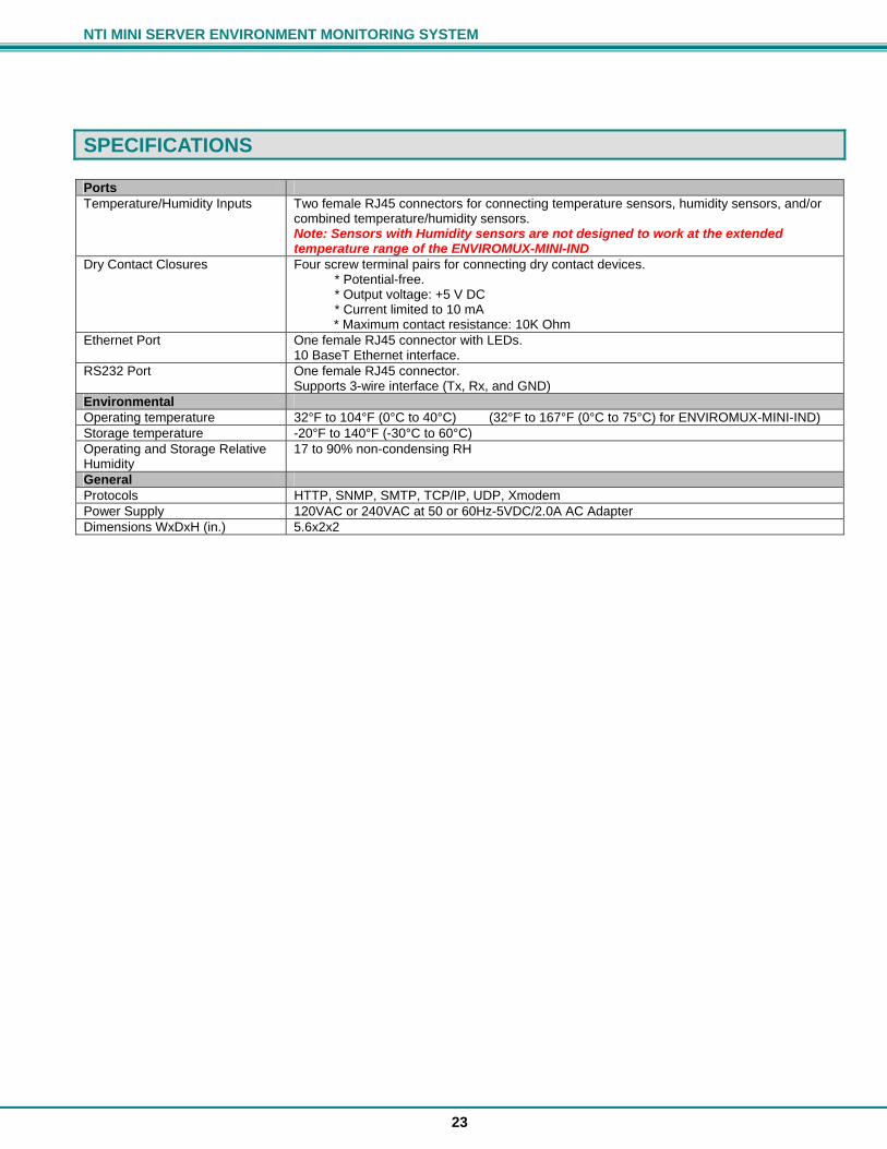
SPECIFICATIONS
Ports Temperature/Humidity Inputs Two female RJ45 connectors for connecting temperature sensors, humidity sensors, and/or
combined temperature/humidity sensors. Note: Sensors with Humidity sensors are not designed to work at the extended temperature range of the ENVIROMUX-MINI-IND
Dry Contact Closures Four screw terminal pairs for connecting dry contact devices. * Potential-free. * Output voltage: +5 V DC * Current limited to 10 mA
* Maximum contact resistance: 10K Ohm Ethernet Port One female RJ45 connector with LEDs.
10 BaseT Ethernet interface. RS232 Port One female RJ45 connector.
Supports 3-wire interface (Tx, Rx, and GND) Environmental Operating temperature 32°F to 104°F (0°C to 40°C) (32°F to 167°F (0°C to 75°C) for ENVIROMUX-MINI-IND) Storage temperature -20°F to 140°F (-30°C to 60°C) Operating and Storage Relative Humidity
17 to 90% non-condensing RH
General Protocols HTTP, SNMP, SMTP, TCP/IP, UDP, Xmodem Power Supply 120VAC or 240VAC at 50 or 60Hz-5VDC/2.0A AC Adapter Dimensions WxDxH (in.) 5.6x2x2

NTI MINI SERVER ENVIRONMENT MONITORING SYSTEM
24
TROUBLESHOOTING Problem Cause Solution Sensors readings are not being updated
• Configuration for sensor updates is not set properly
• Browser is incorrectly going to cache for updates
• Configure sensor updates under General Settings (page 10)
• Clear browser cache, reload page
Sensor alerts are not being reported
• Network settings are not correct • Required Notify addresses are not listed
• Configure Network settings (page 11) • Configure Email addresses (page 12)
I cannot connect to the ENVIROMUX-MINI over the Ethernet
• Cable not connected • IP address not correct • User not listed by administrator
• Check cable connections • Configure Network settings • Have administrator add a user
ENVIROMUX locks-up (or seems to be disabled)
• SMTP settings not correct- unit cannot send alerts via email
• Refer to page 12 and make sure the email configurations settings are correct. Cycle power on the ENVIROMUX-MINI to get access to the configuration pages.
Sensor summary page fails to list sensors
• Browser is incorrectly going to the cache for updates. Observed in both Netscape and Firefox browsers (all versions).
• Clear browser cache and reload • Disable caching within the browser • Use Internet Explorer 6.0 or higher for
web configuration
E-mail message body is missing from E-mail alerts.
E-mail or spam filter configurations on E-mail server
• Create E-mail account for ENVIROMUX-MINI on E-mail server
• Assign E-mail address from account created in the previous step to ENVIROMUX-MINI on the E-mail configuration page
• Verify that spam filter settings are configured properly on E-mail server
• Verify any automated signature/ disclaimer generation settings on E-mail server Verify any MIME conversion settings on mail server (ENVIROMUX-MINI alerts are sent as plain text 7-bit ASCII)
NTI MINI SERVER ENVIRONMENT MONITORING SYSTEM
25
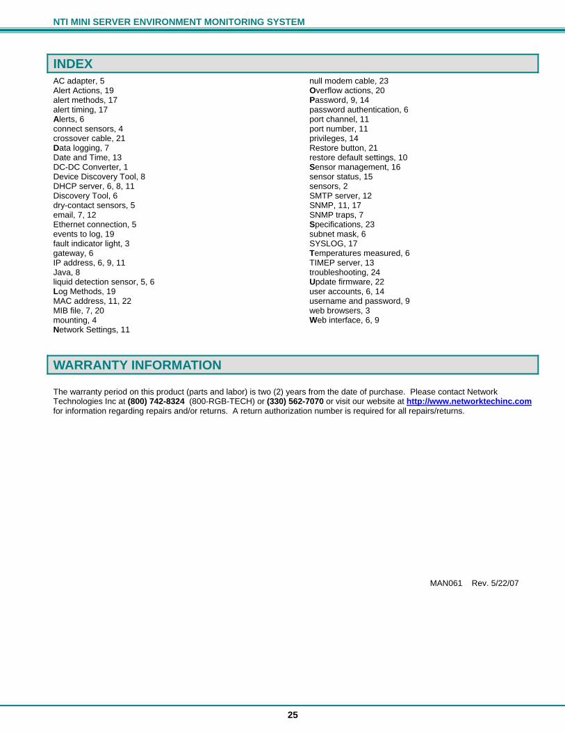
INDEX AC adapter, 5 Alert Actions, 19 alert methods, 17 alert timing, 17 Alerts, 6 connect sensors, 4 crossover cable, 21 Data logging, 7 Date and Time, 13 DC-DC Converter, 1 Device Discovery Tool, 8 DHCP server, 6, 8, 11 Discovery Tool, 6 dry-contact sensors, 5 email, 7, 12 Ethernet connection, 5 events to log, 19 fault indicator light, 3 gateway, 6 IP address, 6, 9, 11 Java, 8 liquid detection sensor, 5, 6 Log Methods, 19 MAC address, 11, 22 MIB file, 7, 20 mounting, 4 Network Settings, 11
null modem cable, 23 Overflow actions, 20 Password, 9, 14 password authentication, 6 port channel, 11 port number, 11 privileges, 14 Restore button, 21 restore default settings, 10 Sensor management, 16 sensor status, 15 sensors, 2 SMTP server, 12 SNMP, 11, 17 SNMP traps, 7 Specifications, 23 subnet mask, 6 SYSLOG, 17 Temperatures measured, 6 TIMEP server, 13 troubleshooting, 24 Update firmware, 22 user accounts, 6, 14 username and password, 9 web browsers, 3 Web interface, 6, 9
WARRANTY INFORMATION The warranty period on this product (parts and labor) is two (2) years from the date of purchase. Please contact Network Technologies Inc at (800) 742-8324 (800-RGB-TECH) or (330) 562-7070 or visit our website at http://www.networktechinc.com for information regarding repairs and/or returns. A return authorization number is required for all repairs/returns. MAN061 Rev. 5/22/07
Related Documents