12 The Open Construction and Building Technology Journal, 2009, 3, 12-32 1874-8368/09 2009 Bentham Open Open Access NSM CFRP Strips for Shear Strengthening of RC Beams: Tests and Me- chanical Model J. A. O. Barros* ,1 , Vincenzo Bianco 2 and Giorgio Monti 3 1 Associate Prof., Dept. of Civil Eng., Univ. of Minho, Azurém, 4810 058 Guimarães, Portugal; 2 PhD Student, Dept. of Structural Eng. and Geotechnics, Univ. of Roma “La Sapienza”, 00197 Roma, Italy; 3 Full Prof., Dept. of Structural Eng. and Geotechnics, Univ. of Roma “La Sapienza”, 00197 Roma, Italy Abstract: The application of Carbon Fiber Reinforced Polymer (CFRP) strips according to the Near Surface Mounted (NSM) technique has proven to be a promising shear strengthening strategy for RC beams, in terms of effectiveness and executability. Nevertheless, several aspects concerning the underlying resisting mechanisms and their mechanical inter- pretation still need to be clarified and organized in a comprehensive model. By a critical overview of the relevant research findings available to date in the analytical modeling domain, it emerges that most of the efforts carried out are mainly de- voted to quantify parameters related to the NSM debonding failure mechanism, on the basis of test set-ups whose geome- try often greatly differs from the actual conditions met in a common T-cross section beam. To give some contribution for the discussion of these subjects, an experimental program was carried out, on T-beams of quasi-real scale and with a given ratio of existing steel stirrups. The main results are presented and analyzed in the present work. In the second part of this work, a new analytical predictive model is proposed. It assumes as possible failure mechanisms: debonding, tensile rupture of the strip and the concrete tensile fracture and allows the interaction between strips to be ac- counted for. The comparison between the results determined by the application of the proposed model and those obtained from experimental research reveals the high predictive accuracy of this model. Keywords: Near Surface Mounted, CFRP, Shear Strengthening, Debonding, Concrete, Critical Diagonal Crack. INTRODUCTION The possibilities of a technique, designated as Near Sur- face Mounted (NSM), for the shear strengthening of rein- forced concrete (RC) beams was started being explored at the beginning of this century [1]. This technique consists on fixing, with epoxy adhesive, fiber reinforced polymer (FRP) bars into grooves opened in the concrete cover of the beam lateral faces. In this exploratory work round bars were used but, recently, the higher effectiveness of square bars was proved [2]. To assess the effectiveness of the NSM technique for the shear strengthening of RC beams, using carbon FRP (CFRP) strips of rectangular cross section, Barros and Dias [3] carried out an experimental program to analyze the influ- ences of the strips’ inclination, beam depth and longitudinal tensile steel reinforcement ratio on the effectiveness of the externally bonded reinforcement (EBR) and NSM strength- ening techniques. Amongst the CFRP strengthening tech- niques, the NSM with strips at 45º resulted to be the most effective, not only in terms of shear resistance increment but also in terms of deformation capacity at failure of the beams. The NSM was also faster and easier to apply than the EBR technique. To simulate the contribution of the NSM strips for the shear strengthening of tested beams, those authors ap- plied the debonding-based formulation proposed by Nanni *Address correspondence to this author at the Dept. of Civil Eng., Univ. of Minho, Azurém, 4810 058 Guimarães, Portugal; E-mail: [email protected] et al. [4], with some adjustments in order to take into ac- count the specificities related to the use of strips instead of round bars [5]. The predictive performance of this model can be found elsewhere [5]. Despite the improvements intro- duced, the existing Debonding-based analytical predictive Model (DM) systematically provided an overestimation, the higher the smaller the spacing, of the experimentally re- corded shear strengthening contribution by NSM CFRP strips. Such overestimation, as further confirmed by experi- mental evidence, can be ascribed to the erroneous assump- tion that the expected failure mechanism is debonding, re- gardless of the influence of concrete tensile strength, interac- tion between consecutive strips, and existing stirrups/strips interaction. The analysis of the failure modes of the beams of the ex- perimental programs carried out by Barros and Dias [3] and Dias and Barros [6], has made clear that it is not possible to extend the debonding-based analytical predictive models to NSM. In fact, in the beams with smaller strip spacing the lateral concrete cover of the web separated from the beam concrete core, indicating that the concrete tensile strength plays a paramount role, by limiting the contribution of these systems to the shear strengthening of RC beams. To give some contribution for the discussion of these subjects, an experimental program was carried out, with T-beams of quasi-real scale and with a given ratio of existing steel stir- rups. The main results are presented and analyzed in the pre- sent work. At the same time a new model is proposed in this work, able of capturing the essential phenomena involved in

Welcome message from author
This document is posted to help you gain knowledge. Please leave a comment to let me know what you think about it! Share it to your friends and learn new things together.
Transcript
12 The Open Construction and Building Technology Journal, 2009, 3, 12-32
1874-8368/09 2009 Bentham Open
Open Access NSM CFRP Strips for Shear Strengthening of RC Beams: Tests and Me-chanical Model J. A. O. Barros*,1, Vincenzo Bianco2 and Giorgio Monti3
1Associate Prof., Dept. of Civil Eng., Univ. of Minho, Azurém, 4810 058 Guimarães, Portugal; 2PhD Student, Dept. of Structural Eng. and Geotechnics, Univ. of Roma “La Sapienza”, 00197 Roma, Italy; 3Full Prof., Dept. of Structural Eng. and Geotechnics, Univ. of Roma “La Sapienza”, 00197 Roma, Italy
Abstract: The application of Carbon Fiber Reinforced Polymer (CFRP) strips according to the Near Surface Mounted (NSM) technique has proven to be a promising shear strengthening strategy for RC beams, in terms of effectiveness and executability. Nevertheless, several aspects concerning the underlying resisting mechanisms and their mechanical inter-pretation still need to be clarified and organized in a comprehensive model. By a critical overview of the relevant research findings available to date in the analytical modeling domain, it emerges that most of the efforts carried out are mainly de-voted to quantify parameters related to the NSM debonding failure mechanism, on the basis of test set-ups whose geome-try often greatly differs from the actual conditions met in a common T-cross section beam. To give some contribution for the discussion of these subjects, an experimental program was carried out, on T-beams of quasi-real scale and with a given ratio of existing steel stirrups. The main results are presented and analyzed in the present work.
In the second part of this work, a new analytical predictive model is proposed. It assumes as possible failure mechanisms: debonding, tensile rupture of the strip and the concrete tensile fracture and allows the interaction between strips to be ac-counted for. The comparison between the results determined by the application of the proposed model and those obtained from experimental research reveals the high predictive accuracy of this model.
Keywords: Near Surface Mounted, CFRP, Shear Strengthening, Debonding, Concrete, Critical Diagonal Crack.
INTRODUCTION
The possibilities of a technique, designated as Near Sur-face Mounted (NSM), for the shear strengthening of rein-forced concrete (RC) beams was started being explored at the beginning of this century [1]. This technique consists on fixing, with epoxy adhesive, fiber reinforced polymer (FRP) bars into grooves opened in the concrete cover of the beam lateral faces. In this exploratory work round bars were used but, recently, the higher effectiveness of square bars was proved [2]. To assess the effectiveness of the NSM technique for the shear strengthening of RC beams, using carbon FRP (CFRP) strips of rectangular cross section, Barros and Dias [3] carried out an experimental program to analyze the influ-ences of the strips’ inclination, beam depth and longitudinal tensile steel reinforcement ratio on the effectiveness of the externally bonded reinforcement (EBR) and NSM strength-ening techniques. Amongst the CFRP strengthening tech-niques, the NSM with strips at 45º resulted to be the most effective, not only in terms of shear resistance increment but also in terms of deformation capacity at failure of the beams. The NSM was also faster and easier to apply than the EBR technique. To simulate the contribution of the NSM strips for the shear strengthening of tested beams, those authors ap-plied the debonding-based formulation proposed by Nanni
*Address correspondence to this author at the Dept. of Civil Eng., Univ. of Minho, Azurém, 4810 058 Guimarães, Portugal; E-mail: [email protected]
et al. [4], with some adjustments in order to take into ac-count the specificities related to the use of strips instead of round bars [5]. The predictive performance of this model can be found elsewhere [5]. Despite the improvements intro-duced, the existing Debonding-based analytical predictive Model (DM) systematically provided an overestimation, the higher the smaller the spacing, of the experimentally re-corded shear strengthening contribution by NSM CFRP strips. Such overestimation, as further confirmed by experi-mental evidence, can be ascribed to the erroneous assump-tion that the expected failure mechanism is debonding, re-gardless of the influence of concrete tensile strength, interac-tion between consecutive strips, and existing stirrups/strips interaction.
The analysis of the failure modes of the beams of the ex-perimental programs carried out by Barros and Dias [3] and Dias and Barros [6], has made clear that it is not possible to extend the debonding-based analytical predictive models to NSM. In fact, in the beams with smaller strip spacing the lateral concrete cover of the web separated from the beam concrete core, indicating that the concrete tensile strength plays a paramount role, by limiting the contribution of these systems to the shear strengthening of RC beams. To give some contribution for the discussion of these subjects, an experimental program was carried out, with T-beams of quasi-real scale and with a given ratio of existing steel stir-rups. The main results are presented and analyzed in the pre-sent work. At the same time a new model is proposed in this work, able of capturing the essential phenomena involved in
NSM CFRP Strips for Shear Strengthening of RC Beams The Open Construction and Building Technology Journal, 2009, Volume 3 13
this strengthening technique, namely: debonding; interaction between strips; concrete tensile fracture; tensile rupture of the strips. This model is described in this work and its per-formance is assessed taking the obtained experimental re-sults.
EXPERIMENTAL PROGRAM
Test Series, Strengthening Technique, Test Setup and Material Properties
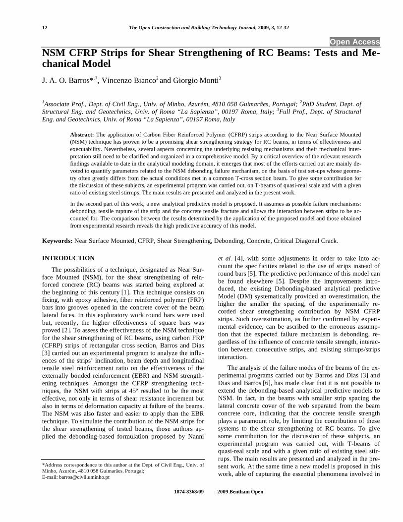
The T-cross section of the twelve RC beams composing the experimental program is represented in Fig. (1). The re-
inforcement was designed to activate shear failure for all tested beams. To have shear failure in only one half-span, a non-symmetric three point load configuration with two dif-ferent shear spans was chosen and high transverse rein-forcement (steel stirrups of 6 mm diameter spaced at 75 mm - φ6@75mm) was placed in the larger beam span Lr, as (Fig. 2) shows. The monitored shorter beam span (Ll) where shear failure should occur, had a “shear span-to-depth” ratio of Ll/d=2.5, where d is the beam effective depth (Fig. 1).
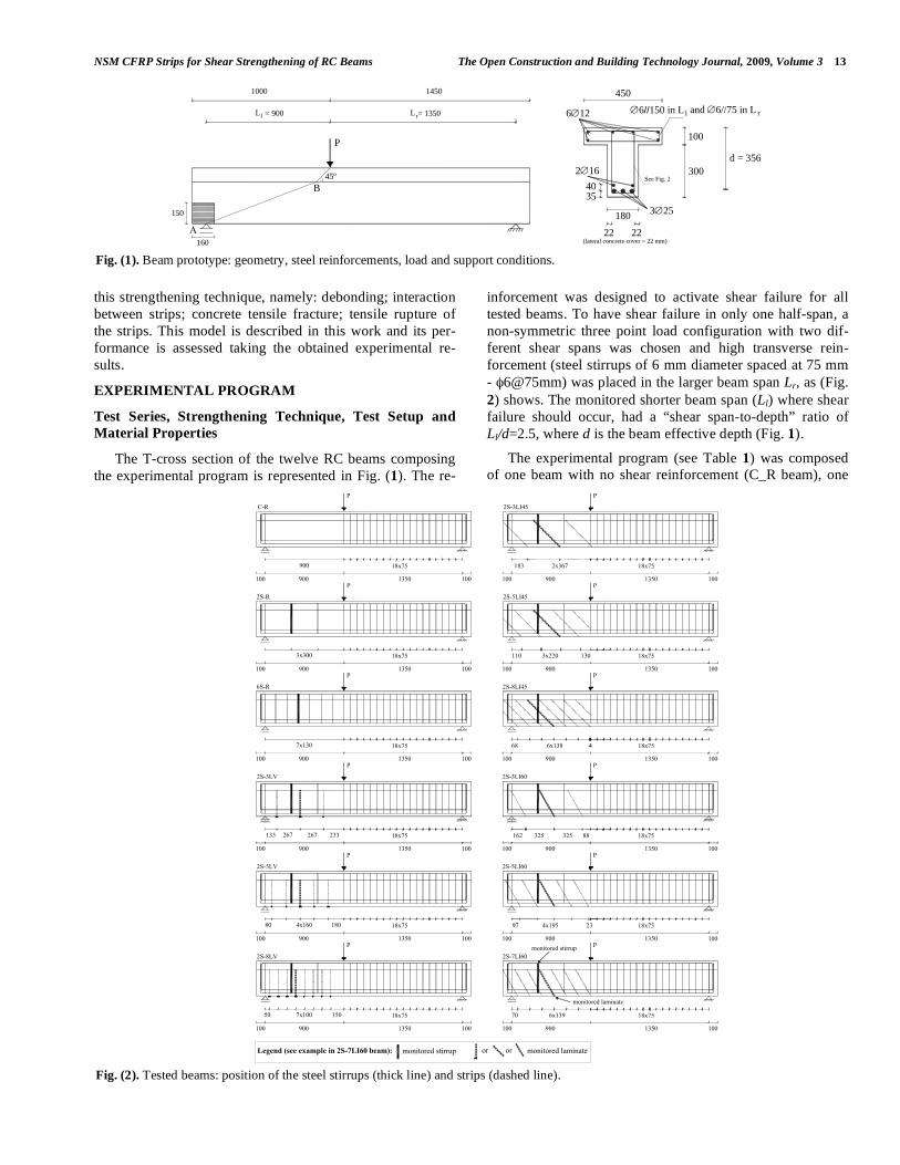
The experimental program (see Table 1) was composed of one beam with no shear reinforcement (C_R beam), one
Fig. (1). Beam prototype: geometry, steel reinforcements, load and support conditions.
Fig. (2). Tested beams: position of the steel stirrups (thick line) and strips (dashed line).
L
1000 1450
= 900l
150
160Α
B
P
45º
Lr = 1350
6∅12 ∅6//150 in L
100
300
180
450
d = 356
3∅25
2∅16
22 22
See Fig. 24035
(lateral concrete cover = 22 mm)
and ∅6//75 in L
l r
3x300 18x75
7x130 18x75
900
900 1350
18x75 2x367183 18x75
233267267133
4x16080 180
18x75
18x75
1507x10050 18x75
110 3x220 130 18x75
68 6x138 18x75
88325162 18x75325
18x7597 4x195
6x13970 18x75
C-R
6S-R
2S-R
2S-8LV
2S-5LV
2S-3LV
2S-8LI45
2S-5LI45
2S-3LI45
2S-7LI60
2S-5LI60
2S-3LI60
P
100 100 1001350900100
100 900 1350 100 900 1350 100100
1001350900100 100 900 1350 100
100 900 1350 100 1001350900100
100 900 1350 100 100 900 1350 100
100 900 1350 100 100 900 1350 100
23
4
P
PP
PP
PP
P
PP
P
monitored laminateLegend (see example in 2S-7LI60 beam): monitored stirrup oror
monitored laminate
monitored stirrup
14 The Open Construction and Building Technology Journal, 2009, Volume 3 Barros et al.
beam with steel stirrups φ6@300mm (2S_R beam, with stir-rups ratio fw! = 0.10%), one beam with steel stirrups φ6@130mm (6S_R beam, fw! = 0.24%), and nine beams of φ6@300mm with different CFRP strengthening arrange-ments on the Ll beam span: three different CFRP ratios (! fw ) and, for each CFRP ratio, three different strips angles ( ! , angle between CFRP fibers direction and beam axis, (Fig. 6) namely, 90º, 45º and 60º. The CFRP shear strength-ening ratio ! fw (see Table 2) was obtained from
( )2 . . . . .100fw f f w fa b b s sin! "= where af = 1.4 mm and bf = 10 mm are the strip cross section dimensions, bw = 180 mm is the width of the beam’s web, and sf is the strips spacing. For the three series of beams with different strips angles, the maximum fw! in each series was evalu-ated to ensure that the beams presented a maximum load similar to the 6S_R reference beam, reinforced with the highest sw! ( ( ). .100fw sw w wA b s! = , where Asw is the cross sectional area of the two arms of a steel stirrup and sw
is the stirrups spacing). In the evaluation of the maximum fw! it was assumed that CFRP works at a stress level corre-
sponding to 0.5% strain, which is a compromise between the value 0.4% recommended by ACI [7] for EBR and the 0.59% value obtained in pullout bending tests on NSM bars [8]. For the intermediate and minimum fw! , the spacing sf for beams with ! equal to 90º, 60º and 45º was evaluated to obtain a similar strips contribution for each fw! . With refer-ence to (Fig. 1), the strips were distributed along the AB line, where A is the beam support at the “test side” and B was obtained assuming a 45º load transfer. To avoid concrete spalling at A, a confinement system made from wet lay-up CFRP sheets (three layers, with fibers aligned with the beam axis) was applied, as shown in Fig. 1. The strengthening pro-cedures are detailed elsewhere [3].
Three point beam bending tests (see Fig. 1) were carried out using a servo closed-loop control equipment, taking the signal read in the linear variable differential transducer (LVDT) placed at the loaded section to control the test at a deflection rate of 0.01 mm/s.
Table 1. Shear Reinforcement and Strengthening Systems in the Tested Beams
Shear reinforcement/strengthening in the smaller shear span (Ll)
Beam label Age at beam test [days] Reinforcement/
Strengthening Quantity (ratios sw! and fw! ) Spacing [mm]
Angle [º]
C_R 65 - - - -
2S_R 61 Steel stirrups 2φ6 with two legs (0.10) 300 90
6S_R 62 Steel stirrups 6φ6 with two legs (0.24) 130 90
Steel stirrups 2φ6 with two legs (0.10) 300 90 2S_3LV 72
CFRP strips 2x3 strips with 1.4x10 mm2 (0.06) 267 90
Steel stirrups 2φ6 with two legs (0.10) 300 90 2S_5LV 71
CFRP strips 2x5 strips with 1.4x10 mm2 (0.10) 160 90
Steel stirrups 2φ6 with two legs (0.10) 300 90 2S_8LV 70
CFRP strips 2x8 strips with 1.4x10 mm2 (0.16) 100 90
Steel stirrups 2φ6 with two legs (0.10) 300 90 2S_3LI45 66
CFRP strips 2x3 strips with 1.4x10 mm2 (0.06) 367 45
Steel stirrups 2φ6 with two legs (0.10) 300 90 2S_5LI45 64
CFRP strips 2x5 strips with 1.4x10 mm2 (0.10) 220 45
Steel stirrups 2φ6 with two legs (0.10) 300 90 2S_8LI45 68
CFRP strips 2x8 strips with 1.4x10 mm2 (0.16) 138 45
Steel stirrups 2φ6 with two legs (0.10) 300 90 2S_3LI60 71
CFRP strips 2x3 strips with 1.4x10 mm2 (0.06) 325 60
Steel stirrups 2φ6 with two legs (0.10) 300 90 2S_5LI60 67
CFRP strips 2x5 strips with 1.4x10 mm2 (0.10) 195 60
Steel stirrups 2φ6 with two legs (0.10) 300 90 2S_7LI60 68
CFRP strips 2x7 strips with 1.4x10 mm2 (0.16) 139 60
( )( ) 100dbAñ wswsw != (stirrups ratio); ( )2 . . . . .100fw f f w fa b b s sin! "= .
NSM CFRP Strips for Shear Strengthening of RC Beams The Open Construction and Building Technology Journal, 2009, Volume 3 15
The concrete compressive strength was evaluated at 28 days and at the age of the beam test, carrying out direct com-pression tests on cylinders of 150 mm diameter and 300 mm height, according to EN 206-1 Standard [9]. Deformed steel bars of 6, 12, 16 and 25 mm diameter were used in the tested beams. The main properties were obtained from uni-axial tensile tests performed according to the recommendations of EN 10002 [10]. The tensile properties of the S&P strips, CFK 150/2000, were characterized by uni-axial tensile tests carried out according to ISO 527-5 [11]. These strips had a cross section of 10×1.4 mm2. Table 2 lists the mean values obtained from these experimental tests.
Main Results and Discussion
Table 3 includes the values of the RSmaxmax FF !
"2 and
RS6maxmax FF ! ratios, where 2
max max maxS RF F F !
" = ! , and
maxF , RSmaxF !2 and RS
maxF !6 represent, respectively, the load carrying capacity of a tested beam, of the 2S_R and of the 6S_R reference beams.
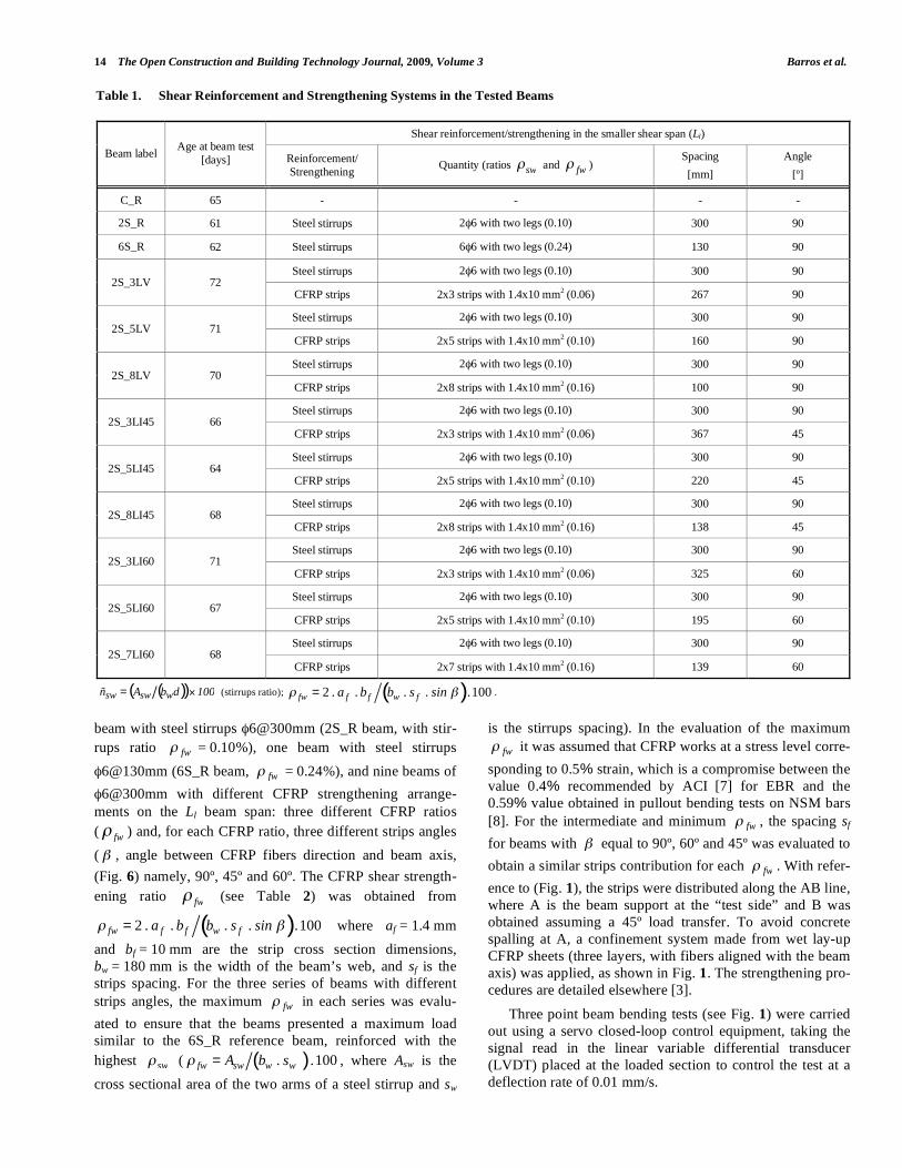
The force-deflection relationships at the loading point of the tested beams are depicted in Fig. (3). If RS
maxF !2 is used as a basis of comparison, Table 3 and Fig. (3) show that, apart
Table 2. Material Properties
Compressive strength Concrete fcm = 26.0 MPa
(at 28 days) fcm = 31.1 MPa
(at 70 days - age of beam tests)
Tensile strength φ6 φ12 φ16 φ25
fsym * 533 MPa 446 MPa 447 MPa 444 MPa Steel
fsum ** 592 MPa 564 MPa 561 MPa 574 MPa
Tensile strength Young’s Modulus Maximum strain *** Thickness CFRP strips
ffum = 2952 MPa ** Efm = 166.6 GPa εfum = 1.77% 1.4 mm
* Mean value of the yield stress; ** Mean value of the maximum stress; *** Obtained from Hooke’s law.
Fig. (3). Force vs. deflection at the loaded-section of the beams strengthened with: (a) minimum; (b) intermediate and (c) maximum CFRP shear strengthening ratio.
0
50
100
150
200
250
300
350
400
0 1 2 3 4 5 6 7Deflection at loaded section [mm]
Forc
e [k
N]
.
2S_R2S_3LV2S_3LI452S_3LI60
(a)
0
50
100
150
200
250
300
350
400
450
0 2 4 6 8Deflection at loaded section [mm]
Forc
e [k
N]
.
2S_R2S_5LV2S_5LI452S_5LI60
(b)
0
50
100
150
200
250
300
350
400
450
0 2 4 6 8Deflection at loaded section [mm]
Forc
e [k
N]
.
2S_R2S_8LV2S_8LI452S_7LI606S_R
(c)
16 The Open Construction and Building Technology Journal, 2009, Volume 3 Barros et al.
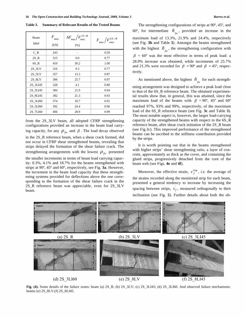
from the 2S_3LV beam, all adopted CFRP strengthening configurations provided an increase in the beam load carry-ing capacity, for any ! fw and ! . The load decay observed in the 2S_R reference beam, when a shear crack formed, did not occur in CFRP shear strengthened beams, revealing that strips delayed the formation of the shear failure crack. The strengthening arrangements with the lowest ! fw presented the smaller increments in terms of beam load carrying capac-ity: 0.3%, 4.1% and 18.7% for the beams strengthened with strips at 90º, 45º and 60º, respectively, see Fig. 3a. However, the increment in the beam load capacity that these strength-ening systems provided for deflections above the one corre-sponding to the formation of the shear failure crack in the 2S_R reference beam was appreciable, even for 2S_3LV beam.
The strengthening configurations of strips at 90º, 45º, and 60º, for intermediate
fwñ , provided an increase in the
maximum load of 13.3%, 21.9% and 24.4%, respectively (see Fig. 3b and Table 3). Amongst the beams strengthened with the highest
fwñ , the strengthening configuration with
! = 60º was the most effective in terms of peak load: a 28.9% increase was obtained, while increments of 25.7% and 21.3% were recorded for ! = 90º and ! = 45º, respec-tively.
As mentioned above, the highest fw
ñ for each strength-
ening arrangement was designed to achieve a peak load close to that of the 6S_R reference beam. The obtained experimen-tal results show that, in general, this was attained, since the maximum load of the beams with ! = 90º, 45º and 60º reached 97%, 93% and 99%, respectively, of the maximum load of the 6S_R reference beam (see Fig. 3c and Table 3). The most notable aspect is, however, the larger load-carrying capacity of the strengthened beams with respect to the 6S_R reference beam, after shear crack initiation of the 2S_R beam (see Fig.3c). This improved performance of the strengthened beams can be ascribed to the stiffness contribution provided by the strips.
It is worth pointing out that in the beams strengthened with higher strips’ shear strengthening ratio, a layer of con-crete, approximately as thick as the cover, and containing the glued strips, progressively detached from the core of the beam web (see Figs. 4e and 4f).
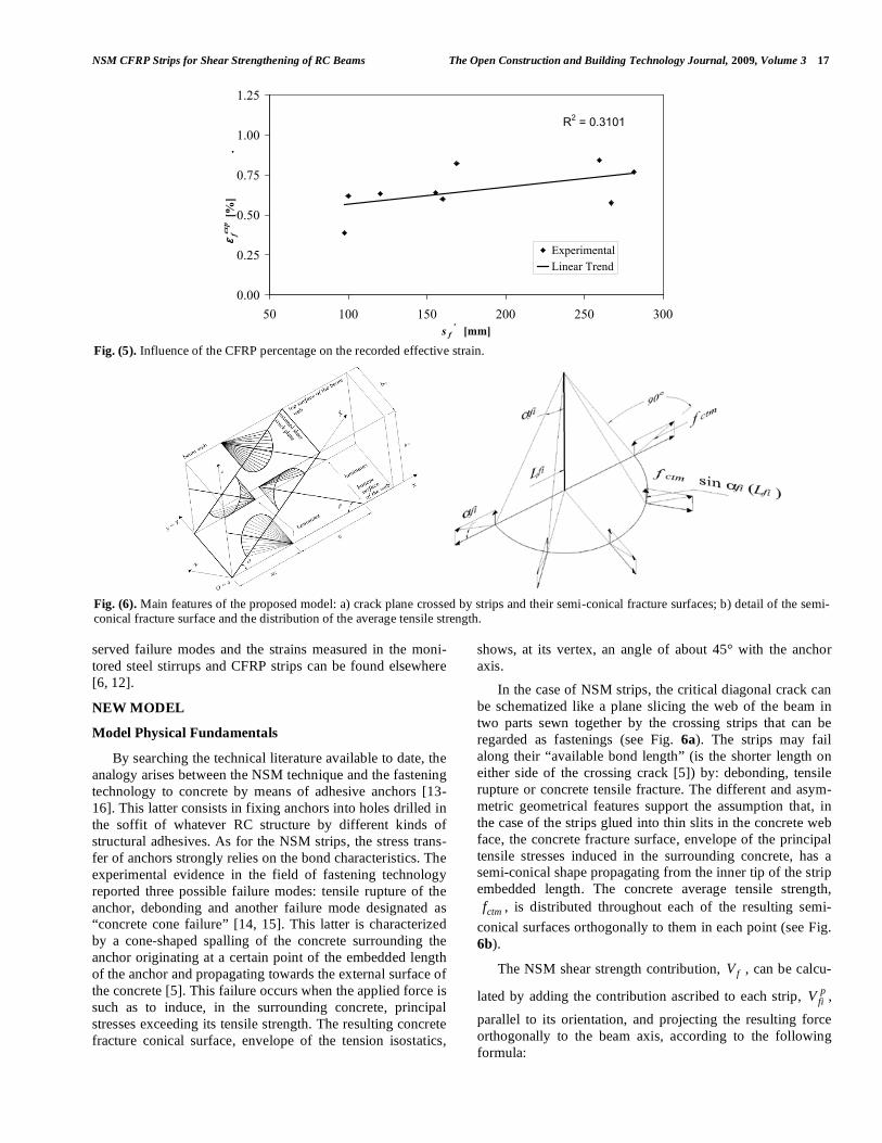
Moreover, the effective strain, expf! , i.e. the average of
the strains recorded along the monitored strip for each beam, presented a general tendency to increase by increasing the spacing between strips, '
fs , measured orthogonally to their inclination (see Fig. 5). Further details about both the ob-
Table 3. Summary of Relevant Results of the Tested Beams
Beam
label maxF
[kN]
RS2maxmax FF !
"
[%]
RS6maxmax FF !
C_R 243 - 0.59
2S_R 315 0.0 0.77
6S_R 410 30.2 1.00
2S_3LV 316 0.3 0.77
2S_5LV 357 13.3 0.87
2S_8LV 396 25.7 0.97
2S_3LI45 328 4.1 0.80
2S_5LI45 384 21.9 0.94
2S_8LI45 382 21.3 0.93
2S_3LI60 374 18.7 0.91
2S_5LI60 392 24.4 0.96
2S_7LI60 406 28.9 0.99
Fig. (4). Some details of the failure zones: beam (a) 2S_R; (b) 2S_3LV; (c) 2S_3LI45; (d) 2S_3LI60. And observed failure mechanisms: beams (e) 2S_8LV;(f) 2S_8LI45.
(a) 2S_R (b) 2S_3LV (c) 2S_3LI45
(d) 2S_3LI60 (e) 2S_8LV (f) 2S_8LI45
Load section
Support
Load section
Support Support
Load section
Support
Load section
NSM CFRP Strips for Shear Strengthening of RC Beams The Open Construction and Building Technology Journal, 2009, Volume 3 17
served failure modes and the strains measured in the moni-tored steel stirrups and CFRP strips can be found elsewhere [6, 12].
NEW MODEL
Model Physical Fundamentals
By searching the technical literature available to date, the analogy arises between the NSM technique and the fastening technology to concrete by means of adhesive anchors [13-16]. This latter consists in fixing anchors into holes drilled in the soffit of whatever RC structure by different kinds of structural adhesives. As for the NSM strips, the stress trans-fer of anchors strongly relies on the bond characteristics. The experimental evidence in the field of fastening technology reported three possible failure modes: tensile rupture of the anchor, debonding and another failure mode designated as “concrete cone failure” [14, 15]. This latter is characterized by a cone-shaped spalling of the concrete surrounding the anchor originating at a certain point of the embedded length of the anchor and propagating towards the external surface of the concrete [5]. This failure occurs when the applied force is such as to induce, in the surrounding concrete, principal stresses exceeding its tensile strength. The resulting concrete fracture conical surface, envelope of the tension isostatics,
shows, at its vertex, an angle of about 45° with the anchor axis.
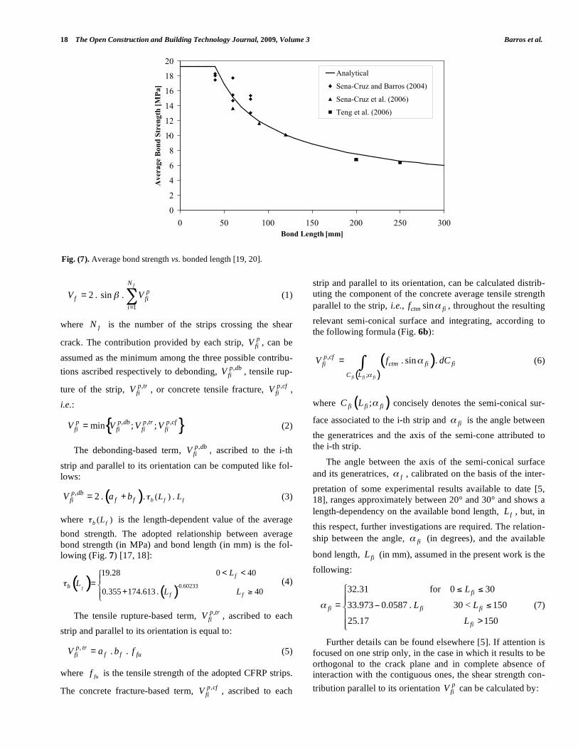
In the case of NSM strips, the critical diagonal crack can be schematized like a plane slicing the web of the beam in two parts sewn together by the crossing strips that can be regarded as fastenings (see Fig. 6a). The strips may fail along their “available bond length” (is the shorter length on either side of the crossing crack [5]) by: debonding, tensile rupture or concrete tensile fracture. The different and asym-metric geometrical features support the assumption that, in the case of the strips glued into thin slits in the concrete web face, the concrete fracture surface, envelope of the principal tensile stresses induced in the surrounding concrete, has a semi-conical shape propagating from the inner tip of the strip embedded length. The concrete average tensile strength,
ctmf , is distributed throughout each of the resulting semi-conical surfaces orthogonally to them in each point (see Fig. 6b).
The NSM shear strength contribution, fV , can be calcu-
lated by adding the contribution ascribed to each strip, pfiV ,
parallel to its orientation, and projecting the resulting force orthogonally to the beam axis, according to the following formula:
Fig. (5). Influence of the CFRP percentage on the recorded effective strain.
Fig. (6). Main features of the proposed model: a) crack plane crossed by strips and their semi-conical fracture surfaces; b) detail of the semi-conical fracture surface and the distribution of the average tensile strength.
R2 = 0.3101
0.00
0.25
0.50
0.75
1.00
1.25
50 100 150 200 250 300s f
' [mm]
ε fex
p [%
]
.
ExperimentalLinear Trend
18 The Open Construction and Building Technology Journal, 2009, Volume 3 Barros et al.
1
2 . sin .fN
pf fi
i
V V!=
= " (1)
where fN is the number of the strips crossing the shear
crack. The contribution provided by each strip, pfiV , can be
assumed as the minimum among the three possible contribu-tions ascribed respectively to debonding, ,p db
fiV , tensile rup-
ture of the strip, ,p trfiV , or concrete tensile fracture, ,p cf
fiV , i.e.:
{ }, , ,min ; ;p p db p tr p cffi fi fi fiV V V V= (2)
The debonding-based term, ,p dbfiV , ascribed to the i-th
strip and parallel to its orientation can be computed like fol-lows:
( ), ( ) .2 . . b f fp db
f ffi L LV a b != + (3)
where ( )b fL! is the length-dependent value of the average bond strength. The adopted relationship between average bond strength (in MPa) and bond length (in mm) is the fol-lowing (Fig. 7) [17, 18]:
( )( )
-0.60233
19.28 0 40
0.355 174.613 . 40f
f
bf f
LL
L L!
< <"#
= $+ %#&
(4)
The tensile rupture-based term, ,p trfiV , ascribed to each
strip and parallel to its orientation is equal to:
, . .p trf f fufiV a b f= (5)
where fuf is the tensile strength of the adopted CFRP strips.
The concrete fracture-based term, ,p cffiV , ascribed to each
strip and parallel to its orientation, can be calculated distrib-uting the component of the concrete average tensile strength parallel to the strip, i.e., sinctm fif ! , throughout the resulting relevant semi-conical surface and integrating, according to the following formula (Fig. 6b):
( )( )
,
;
. sin .fi fi fi
p cfctm fi fifi
C L
V f dC!
!= " (6)
where ( );!fi fi fiC L concisely denotes the semi-conical sur-
face associated to the i-th strip and fi! is the angle between the generatrices and the axis of the semi-cone attributed to the i-th strip.
The angle between the axis of the semi-conical surface and its generatrices, f! , calibrated on the basis of the inter-pretation of some experimental results available to date [5, 18], ranges approximately between 20° and 30° and shows a length-dependency on the available bond length, fL , but, in this respect, further investigations are required. The relation-ship between the angle, fi! (in degrees), and the available
bond length, fiL (in mm), assumed in the present work is the following:
32.31 for 0 30
33.973 0.0587 . 30 < 150
25.17 150
fi
fi fi fi
fi
L
L L
L
!
" # #$$
= % #&$
>$'
(7)
Further details can be found elsewhere [5]. If attention is focused on one strip only, in the case in which it results to be orthogonal to the crack plane and in complete absence of interaction with the contiguous ones, the shear strength con-tribution parallel to its orientation p
fiV can be calculated by:
Fig. (7). Average bond strength vs. bonded length [19, 20].
0
2
4
6
8
10
12
14
16
18
20
0 50 100 150 200 250 300Bond Length [mm]
Ave
rage
Bon
d St
reng
th [M
Pa]
.
Analytical
Sena-Cruz and Barros (2004)
Sena-Cruz et al. (2006)
Teng et al. (2006)
NSM CFRP Strips for Shear Strengthening of RC Beams The Open Construction and Building Technology Journal, 2009, Volume 3 19
( ) 2 2( ) . ;min 2 . . . ; . . .2b fi fi
pf f f f fu ctm fi fifi L LV a b a b f f tg L!
"#
$ %& '= +( )* +
, -. /
(8)
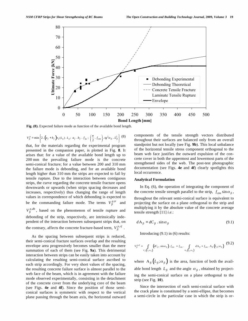
that, for the materials regarding the experimental program presented in the companion paper, is plotted in Fig. 8. It arises that: for a value of the available bond length up to 200 mm the prevailing failure mode is the concrete semi-conical fracture; for a value between 200 and 310 mm the failure mode is debonding, and for an available bond length higher than 310 mm the strips are expected to fail by tensile rupture. Due to the interaction between contiguous strips, the curve regarding the concrete tensile fracture opens downwards or upwards (when strips spacing decreases and increases, respectively) thus changing the range of length values in correspondence of which debonding is expected to be the commanding failure mode. The terms ,p tr
fiV and ,p db
fiV , based on the phenomenon of tensile rupture and debonding of the strip, respectively, are intrinsically inde-pendent of the interaction between subsequent strips that, on the contrary, affects the concrete fracture-based term, ,p cf
fiV .
As the spacing between subsequent strips is reduced, their semi-conical fracture surfaces overlap and the resulting envelope area progressively becomes smaller than the mere summation of each of them (see Fig. 9a). This detrimental interaction between strips can be easily taken into account by calculating the resulting semi-conical surface ascribed to each strip accordingly. For very short values of the spacing, the resulting concrete failure surface is almost parallel to the web face of the beam, which is in agreement with the failure mode observed experimentally, consisting in the detachment of the concrete cover from the underlying core of the beam (see Figs. 4e and 4f). Since the position of those semi-conical surfaces is symmetric with respect to the vertical plane passing through the beam axis, the horizontal outward
components of the tensile strength vectors distributed throughout their surfaces are balanced only from an overall standpoint but not locally (see Fig. 9b). This local unbalance of the horizontal tensile stress component orthogonal to the beam web face justifies the outward expulsion of the con-crete cover in both the uppermost and lowermost parts of the strengthened sides of the web. The post-test photographic documentation (see Figs. 4e and 4f) clearly spotlights this local occurrence.
Analytical Formulation
In Eq. (6), the operation of integrating the component of the concrete tensile strength parallel to the strip, sinctm fif ! , throughout the relevant semi-conical surface is equivalent to projecting the surface on a plane orthogonal to the strip and multiplying it by the absolute value of the concrete average tensile strength [11] i.e.:
. sinfi fi fid dC !" = (9.1)
Introducing (9.1) in (6) results:
( )( ) ( )
( ),
; ;
. sin . . . ;fi fi fi fi fi fi
p cffi fi ctm ctm fi ctm fi fi fifi
C L L
V dC f f d f L! !
! !
"
= = " = "# # (9.2)
where ( );fi fi fiL !" is the area, function of both the avail-
able bond length fiL and the angle fi! , obtained by project-ing the semi-conical surface on a plane orthogonal to the strip (see Fig. 10).
Since the intersection of each semi-conical surface with the crack plane is constituted by a semi-ellipse, that becomes a semi-circle in the particular case in which the strip is or-
Fig. (8). Expected failure mode as function of the available bond length.
0
10
20
30
40
50
60
70
80
0 50 100 150 200 250 300 350 400 450 500Bond Length [mm]
Ulti
mat
e Fo
rce
[kN
]
Debonding ExperimentalDebonding TheoreticalConcrete Tensile FractureLaminate Tensile RuptureEnvelope
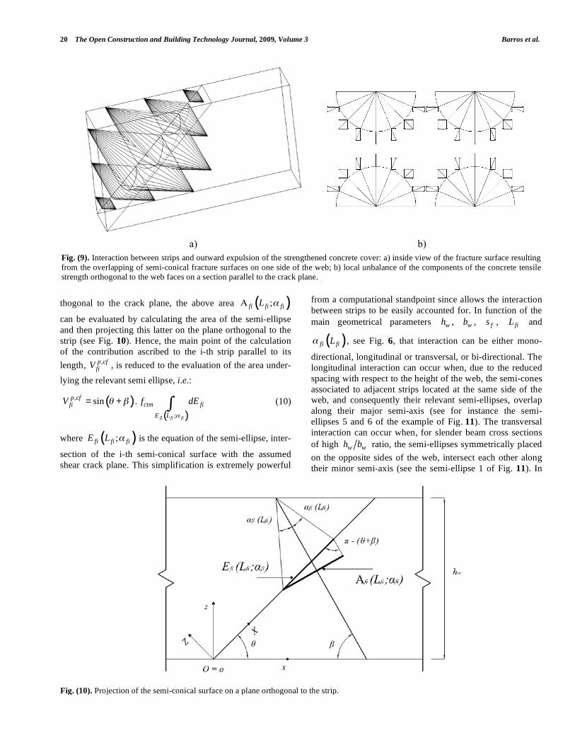
20 The Open Construction and Building Technology Journal, 2009, Volume 3 Barros et al.
thogonal to the crack plane, the above area ( );fi fi fiL !"
can be evaluated by calculating the area of the semi-ellipse and then projecting this latter on the plane orthogonal to the strip (see Fig. 10). Hence, the main point of the calculation of the contribution ascribed to the i-th strip parallel to its length, ,p cf
fiV , is reduced to the evaluation of the area under-lying the relevant semi ellipse, i.e.:
( )( )
,
;
sin .fi fi fi
p cfctm fifi
E L
V f dE!
" #= + $ (10)
where ( );!fi fi fiE L is the equation of the semi-ellipse, inter-
section of the i-th semi-conical surface with the assumed shear crack plane. This simplification is extremely powerful
from a computational standpoint since allows the interaction between strips to be easily accounted for. In function of the main geometrical parameters wh , wb , fs , fiL and
( )fi fiL! , see Fig. 6, that interaction can be either mono-
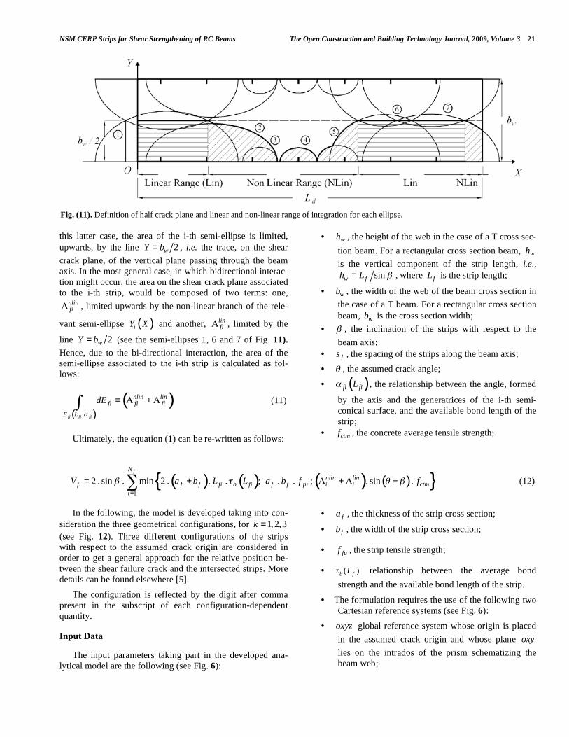
directional, longitudinal or transversal, or bi-directional. The longitudinal interaction can occur when, due to the reduced spacing with respect to the height of the web, the semi-cones associated to adjacent strips located at the same side of the web, and consequently their relevant semi-ellipses, overlap along their major semi-axis (see for instance the semi-ellipses 5 and 6 of the example of Fig. 11). The transversal interaction can occur when, for slender beam cross sections of high w wh b ratio, the semi-ellipses symmetrically placed on the opposite sides of the web, intersect each other along their minor semi-axis (see the semi-ellipse 1 of Fig. 11). In
Fig. (9). Interaction between strips and outward expulsion of the strengthened concrete cover: a) inside view of the fracture surface resulting from the overlapping of semi-conical fracture surfaces on one side of the web; b) local unbalance of the components of the concrete tensile strength orthogonal to the web faces on a section parallel to the crack plane.
Fig. (10). Projection of the semi-conical surface on a plane orthogonal to the strip.
a) b)
NSM CFRP Strips for Shear Strengthening of RC Beams The Open Construction and Building Technology Journal, 2009, Volume 3 21
this latter case, the area of the i-th semi-ellipse is limited, upwards, by the line 2wY b= , i.e. the trace, on the shear crack plane, of the vertical plane passing through the beam axis. In the most general case, in which bidirectional interac-tion might occur, the area on the shear crack plane associated to the i-th strip, would be composed of two terms: one,
nlinfi! , limited upwards by the non-linear branch of the rele-
vant semi-ellipse ( )iY X and another, linfi! , limited by the
line 2wY b= (see the semi-ellipses 1, 6 and 7 of Fig. 11). Hence, due to the bi-directional interaction, the area of the semi-ellipse associated to the i-th strip is calculated as fol-lows:
( )( )
;fi fi fi
nlin linfi fi fi
E L
dE!
= " +"# (11)
Ultimately, the equation (1) can be re-written as follows:
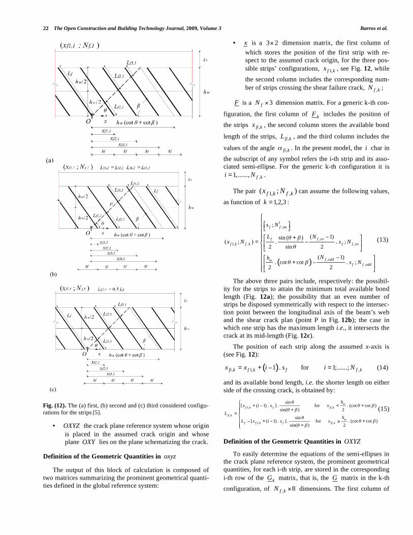
In the following, the model is developed taking into con-sideration the three geometrical configurations, for 1,2,3k = (see Fig. 12). Three different configurations of the strips with respect to the assumed crack origin are considered in order to get a general approach for the relative position be-tween the shear failure crack and the intersected strips. More details can be found elsewhere [5].
The configuration is reflected by the digit after comma present in the subscript of each configuration-dependent quantity.
Input Data
The input parameters taking part in the developed ana-lytical model are the following (see Fig. 6):
• wh , the height of the web in the case of a T cross sec-tion beam. For a rectangular cross section beam, wh is the vertical component of the strip length, i.e.,
sinw fh L != , where fL is the strip length;
• wb , the width of the web of the beam cross section in the case of a T beam. For a rectangular cross section beam, wb is the cross section width;
• ! , the inclination of the strips with respect to the beam axis;
• fs , the spacing of the strips along the beam axis; • ! , the assumed crack angle;
• ( )fi fiL! , the relationship between the angle, formed
by the axis and the generatrices of the i-th semi-conical surface, and the available bond length of the strip;
• ctmf , the concrete average tensile strength;
• fa , the thickness of the strip cross section;
• fb , the width of the strip cross section;
• fuf , the strip tensile strength;
• ( )b fL! relationship between the average bond strength and the available bond length of the strip.
• The formulation requires the use of the following two Cartesian reference systems (see Fig. 6):
• oxyz global reference system whose origin is placed in the assumed crack origin and whose plane oxy lies on the intrados of the prism schematizing the beam web;
( ) ( ) ( ) ( ){ }1
2 . sin . min 2 . . . ; . . ; . sin .fN
nlin linf f f fi b fi f f fu i i ctm
i
V a b L L a b f f! " # !=
= + $ +$ +% (12)
Fig. (11). Definition of half crack plane and linear and non-linear range of integration for each ellipse.
22 The Open Construction and Building Technology Journal, 2009, Volume 3 Barros et al.
• OXYZ the crack plane reference system whose origin is placed in the assumed crack origin and whose plane OXY lies on the plane schematizing the crack.
Definition of the Geometric Quantities in oxyz
The output of this block of calculation is composed of two matrices summarizing the prominent geometrical quanti-ties defined in the global reference system:
• x is a 3 2! dimension matrix, the first column of which stores the position of the first strip with re-spect to the assumed crack origin, for the three pos-sible strips’ configurations, 1,f kx , see Fig. 12, while the second column includes the corresponding num-ber of strips crossing the shear failure crack, ,f kN ;
F is a 3fN ! dimension matrix. For a generic k-th con-
figuration, the first column of kF includes the position of the strips ,fi kx , the second column stores the available bond
length of the strips, ,fi kL , and the third column includes the
values of the angle ,fi k! . In the present model, the i char in the subscript of any symbol refers the i-th strip and its asso-ciated semi-ellipse. For the generic k-th configuration it is
,1,......, f ki N= .
The pair 1, ,( ; )f k f kx N can assume the following values,
as function of 3,2,1=k :
( )
,int
,1, , ,
,,
;
( 1)sin ( )( ; ) ;
2 sin 2
( 1)cot cot ;
2 2
. .
. .
lf f
f f evf k f k f f ev
f oddwf f odd
s N
L Nx N s N
Nhs N
! "
!
! "
#+= #
#+ #
$%& '( )%%& '%*+ ,( )%%& '%+ ,%( )-
(13)
The above three pairs include, respectively: the possibil-ity for the strips to attain the minimum total available bond length (Fig. 12a); the possibility that an even number of strips be disposed symmetrically with respect to the intersec-tion point between the longitudinal axis of the beam’s web and the shear crack plan (point P in Fig. 12b); the case in which one strip has the maximum length i.e., it intersects the crack at its mid-length (Fig. 12c).
The position of each strip along the assumed x-axis is (see Fig. 12):
( ), 1, ,1 . for 1;......;fi k f k f f kx x i s i N= + ! = (14)
and its available bond length, i.e. the shorter length on either side of the crossing crack, is obtained by:
1, ,
,
1, ,
sin[ ( 1) . ] . for . (cot cot )
sin( ) 2
sin[ ( 1) . ] . for . (cot cot )
sin( ) 2
wf k f fi k
fi kw
f f k f fi k
hx i s x
Lh
L x i s x
!! "
! "
!! "
! "
+ # < ++
=
# + # $ ++
%&&'&&(
(15)
Definition of the Geometric Quantities in OXYZ
To easily determine the equations of the semi-ellipses in the crack plane reference system, the prominent geometrical quantities, for each i-th strip, are stored in the corresponding i-th row of the kG matrix, that is, the G matrix in the k-th configuration, of , 8f kN ! dimensions. The first column of
Fig. (12). The (a) first, (b) second and (c) third considered configu-rations for the strips [5].
(a)(a)
(b)
(c)
NSM CFRP Strips for Shear Strengthening of RC Beams The Open Construction and Building Technology Journal, 2009, Volume 3 23
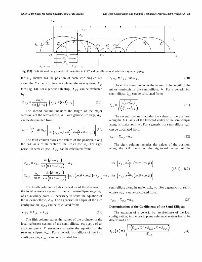
the kG matrix has the position of each strip singled out along the OX axis of the crack plane reference system, fiX
(see Fig. 13). For a generic i-th strip, ,fi kX can be evaluated by:
( )( ), 1,
sin . 1 .sinfi k f k fX x i s!
! "# $= + %& '+
(16)
The second column includes the length of the major semi-axis of the semi-ellipse, a . For a generic i-th strip, ,i ka can be determined from:
( ) ( ),
, ,, ,
1 1. sin2 sin sinfi k
i k fi kfi k fi k
La !
! " # # " !
$ %& '= +& '+ + + () *
(17)
The third column stores the values of the position, along the OX axis, of the center of the i-th ellipse oX . For a ge-neric i-th semi-ellipse, ,oi kX can be calculated from:
The fourth column includes the values of the abscissa, in the local reference system of the i-th semi-ellipse 1 2 3i i ioe e e of an auxiliary point P necessary to write the equation of the relevant ellipse, 1Pie . For a generic i-th ellipse of the k-th configuration, 1 ,Pi ke can be calculated from:
1 , , ,Pi k fi k oi ke X X= ! (19)
The fifth column stores the values of the ordinate, in the local reference system of the semi-ellipse, 1 2 3i i ioe e e , of an auxiliary point P necessary to write the equation of the relevant ellipse, 2Pie . For a generic i-th ellipse of the k-th configuration, 2 ,Pi ke can be calculated from:
2 , , ,. tanPi k fi k fi ke L != (20)
The sixth column includes the values of the length of the minor semi-axis of the semi-ellipse, b . For a generic i-th semi-ellipse ,i kb can be calculated from:
( )
2 2, 2 ,
, 2 2, 1 ,
.i k Pi ki k
i k Pi k
a eb
a e=
! (21)
The seventh column includes the values of the position, along the OX axis, of the leftward vertex of the semi-ellipse along its major axis, 1v . For a generic i-th semi-ellipse 1 ,i kv can be calculated from:
1 , , ,i k oi k i kv X a= ! (22)
The eight column includes the values of the position, along the OX axis, of the rightward vertex of the
semi-ellipse along its major axis, 2v . For a generic i-th semi-ellipse 2 ,i kv can be calculated from:
2 , , ,i k oi k i kv X a= + (23)
Determination of the Coefficients of the Semi-Ellipses
The equation of a generic i-th semi-ellipse of the k-th configuration, in the crack plane reference system has to be determined i.e.:
( )( )2
1, 3, 4,,
2,
. .i k i k i ki k
i k
E X E X EY X
E
+ += + ! (24)
Fig. (13). Definition of the geometrical quantities in OXY and the ellipse local reference system oie1ie2i.
( )( )
( )
( )( )
( ) ( )
,, , , ,
,
,, , , ,
,
sin. for . cot cot
2sin
sin. . cot cot for . cot cot
sin 2sin
fi k woi k fi k i k fi k
fi k
fi kw woi k w fi k i k fi k
fi k
hX x a x
h hX h x a x
! "# !
! # "
! "# ! # !
# ! # "
$ % & '( = + < +) *( + % + ,(-
%( & '. /= % + % % 0 +( ) *1 2
+ % + ,(3
(18.1) 18.2)
24 The Open Construction and Building Technology Journal, 2009, Volume 3 Barros et al.
For this purpose, the coefficients of the semi-ellipses are stored in the E matrix that, for the k-th configuration ( kE ) has , 4f kN ! dimensions. The first to fourth columns of the
E matrix store the values of the coefficients of the semi-ellipses. For a generic i-th semi-ellipse of the k-th configura-tion, these coefficients can be calculated from:
Determination of the Auxiliary Matrices of Integration Points
It is worth determining, even if they are not strictly nec-essary for the implementation of the algorithm, some auxil-iary matrices i.e. 1p
kX , 2pkX , q
kX , ekY , kM , kN ,
kQ since
they condense some operations that, otherwise, should be repeated several times. 1pX and 2pX are two f fN N! di-mensions symmetric matrices containing, respectively, the abscissa of the first, 1p
ijX , and second, 2pijX , intersection
points, if actually existing, between the i-th and j-th semi-ellipses. For the k-th configuration, the generic terms 1
,p
ij kX
and 2,
pij kX of the 1p
kX and 2pkX matrices are determined,
respectively, from Eq. (27.1) and (27.2) if the following conditions, Eqs. (26.1-2), are satisfied:
( )1, 2, 1, 2,. . 0j k i k i k j kE E E E! " (26.1)
( )( )
2, 3, 2, 3, ,1,
1, 2, 1, 2,
. .
2 . . .i k j k j k i k ij kp
ij kj k i k i k j k
E E E EX
E E E E
! ! ! "=
! (27.1)
( )( )
2, 3, 2, 3, ,2,
1, 2, 1, 2,
. .
2 . .i k j k j k i k ij kp
ij kj k i k i k j k
E E E EX
E E E E
! ! + "=
! (27.2)
Otherwise, if the following condition is satisfied:
( )1, 2, 1, 2,. . 0j k i k i k j kE E E E! = (28)
the i-th and j-th semi-ellipses are intersecting in only one point, and the abscissa in the OX axis is given by:
( )
( )
2, 4, 2, 4,1,
2, 3, 2, 3,
. .
. .
i k j k j k i kpij k
i k j k j k i k
E E E EX
E E E E
!= !
!
(29)
In this case a “non-value”, represented by an asterisk, is assigned to the corresponding cell of the 2p
kX matrix, i.e.:
2, *p
ij kX = (30) Note that a “non-value” term is not zero since this latter
has a physical meaning representing the position, in OXZ ,
of the assumed crack origin. The general term 1/ 2,
pij kX (repre-
sents both 1,
pij kX and 2
,p
ij kX ) calculated as above specified, will be stored in the j-th column of the i-th row of the rele-vant auxiliary matrix 1/ 2p
kX if it is such as to satisfy the fol-lowing condition:
( ) ( )21/ 2 1/ 2
1, 3, 4,, ,
2,
. .0
p pi k i k i kij k ij k
i k
E X E X E
E
! "+ +# $% &' > (31)
If for the general solution 1/ 2,
pij kX , neither the conditions
of Eqs. (26 and 31) nor Eqs. (28 and31) are satisfied, the corresponding cell of the relevant matrix 1/ 2p
kX has to be filled with a “non value”, e.g., an asterisk. Throughout the following calculations, each time neither the existence nor acceptance conditions of a real value are fulfilled, the corre-sponding cell has to be filled with a “non-value”. qX is a
2fN ! dimensions matrix containing, in each i-th row, the
abscissa of the left 1qiX and right 2
qiX intersection, if actu-
ally existing, of the relevant i-th semi-ellipse with the straight line 2wY b= . For the general k-th configuration,
the first column term of the i-th row, 1,qi kX , and the second
column one, 2,qi kX , of the q
kX matrix are calculated, respec-tively, from the following Eqs.:
( )2 23, 3, 1, 2, 4,
1,1,
4 . . 4
2 .i k i k i k i k w i kq
i ki k
E E E E b EX
E
! ! ! += (32.1)
( )2 23, 3, 1, 2, 4,
2,1,
4 . . 4
2 .i k i k i k i k w i kq
i ki k
E E E E b EX
E
! + ! += (32.2)
if the following condition is satisfied:
( )2 2, 3, 1, 2, 4,4 . . 4 0i k i k i k i k w i kE E E b E! = " + # (33)
eY is a 2fN ! dimensions matrix containing, in each i-th row, the ordinate assumed by the i-th semi-ellipse in cor-respondence of 0X = , and in correspondence of dX L= , if the semi-ellipse actually passes through those abscissa val-ues. For the generic k-th configuration, the first term 1,
ei kY of
the i-th row of the ekY matrix is a real number, indicating
2, 2, 3, 3, 2, 1, 2, 1, 2, 2, 3, 2, 3,. . 4 . . . . . . 0ij k i k j k i k j k j k i k i k j k i k j k j k i kE E E E E E E E E E E E! " ! " ! "# = $ $ $ $ >% & % & % & (26.2)
21, ,i k i kE b= ; 2
2, ,i k i kE a= ; 23, , ,2 . .i k i k oi kE b X= ! ; 2 2 2 2
4, , , , ,. .i k i k oi k i k i kE b X a b= ! (25)
NSM CFRP Strips for Shear Strengthening of RC Beams The Open Construction and Building Technology Journal, 2009, Volume 3 25
that the relevant semi-ellipse effectively passes through 0X = if the following condition is satisfied:
4,
2,0i k
i k
EE
! " (34)
and in that case the corresponding value 1,e
i kY is equal to:
4,1,
2,
i kei k
i k
EY
E= + ! (35)
Likewise, the second term 2,e
i kY of the i-th row of the ma-
trix ekY is constituted of a real value, meaning that the rele-
vant i-th semi-ellipse of the k-th configuration effectively passes through dX L= if the following condition is satis-fied:
( )24, 3, 1,
2,
. .0
i k i k d i k d
i k
E E L E L
E
+ +! " (36)
and the corresponding value 2,e
i kY is determined by the fol-lowing expression:
( )21, 3, 4,
2,2,
. .i k d i k d i kei k
i k
E L E L EY
E
+ += + ! (37)
M , N , Q are f fN N! dimensions matrices contain-
ing, respectively, the coefficients ijM , ijN and ijQ with
, 1,...., fi j N= . For the generic k-th configuration, the gen-
eral terms ,ij kM , ,ij kN , ,ij kQ of the kM , kN and k
Q ma-
trices are calculated as follows:
1,1,,
2, 2,
j ki kij k
i k j k
EEM
E E
! "# $% &= '( )( )% &* +, -
; 3,3,,
2, 2,
j ki kij k
i k j k
EEN
E E
! "# $% &= '( )( )% &* +, -
;
4,4,,
2, 2,
j ki kij k
i k j k
EEQ
E E
! "# $% &= '( )( )% &* +, -
(38)
where 1,i kE , 2,i kE , 3,i kE , 4,i kE and 1,j kE , 2,j kE , 3,j kE ,
4,j kE are, respectively, the coefficients of the i-th and j-th semi-ellipses in the k-th configuration stored in the relevant rows of the kE matrix.
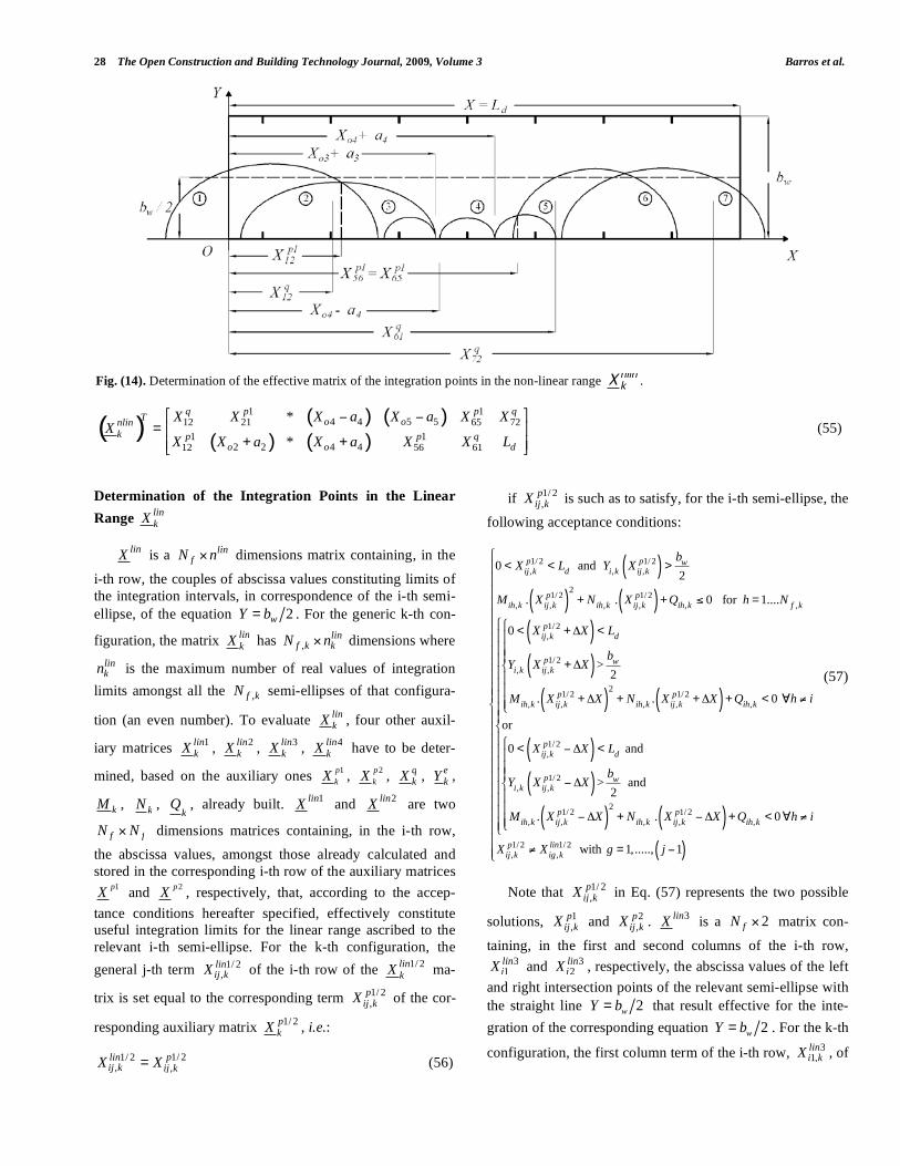
Determination of the Integration Points in the Non Lin-ear Range nlin
kX
nlinX is a nlinfN n! dimensions matrix containing, in
the i-th row, the couples of abscissa values constituting lim-its of the integration intervals for the relevant i-th semi-ellipse equation ( )iY X . For the k-th configuration, the ma-
trix nlinkX has ,
nlinf k kN n! dimensions where nlin
kn is the
maximum number of real values of integration limits amongst all the ,f kN ellipses of that configuration (an even
number). To evaluate nlinkX , five other auxiliary matrices
1nlinkX , 2nlin
kX , 3nlinkX , 4nlin
kX , 5nlinkX have to be deter-
mined, based on both the auxiliary ones 1pkX , 2p
kX , qkX ,
ekY , kM , kN ,
kQ , output of the previous block of calcula-
tions, and the matrix of the semi-ellipses geometrical proper-ties, kG .
1nlinX and 2nlinX are two f fN N! dimensions matrices
containing, in the i-th row, the abscissa values, amongst those already calculated and stored in the corresponding i-th row, respectively, of the auxiliary matrices 1pX and 2pX , that, according to the acceptance conditions hereafter speci-fied, effectively constitute useful integration limits for the relevant i-th semi-ellipse equation. For the k-th configura-tion, the general j-th term 1/ 2
,nlinij kX of the i-th row of the
1/ 2nlinkX matrix is set equal to the corresponding term 1/ 2
,pij kX
of the corresponding auxiliary matrix 1/ 2pkX , i.e.:
1/ 21/ 2, ,
pnlinij k ij kX X= (39)
if 1/ 2,
pij kX is such as to satisfy, for the i-th semi-ellipse, the
following acceptance conditions:
0 < Xij,kp1/ 2 < Ld and Yi,k Xij,k
p1/ 2( ) <bw2
Mih,k . Xij,kp1/ 2( )
2+ Nih,k . Xij,k
p1/ 2( ) + Qih,k ! 0
for h = 1....N f ,k
0 < Xij,kp1/ 2 +"X( ) < Ld and
0 < Yi,k Xij,kp1/ 2 +"X( ) <
bw2
and
Mih,k . Xij,kp1/ 2 +"X( )
2+ Nih,k . Xij,k
p1/ 2 +"X( ) + Qih,k < 0
# h = 1....N f ,k and h $ i
%
&
''''
(
''''
or
0 < Xij,kp1/ 2 ) "X( ) < Ld and
0 < Yi,k Xij,kp1/ 2 ) "X( ) <
bw2
and
Mih,k . Xij,kp1/ 2 ) "X( )
2+ Nih,k . Xij,k
p1/ 2 ) "X( ) + Qih,k < 0
# h = 1....N f ,k and h $ i
%
&
''''
(
''''
%
&
''''''''''
(
''''''''''
Xij,kp1/ 2 $ Xig ,k
nlin1/ 2 with g = 1,....., j )1( )
%
&
''''''''''''''''''''''''
(
''''''''''''''''''''''''
(40)
in which the term X! indicates an infinitesimally small length along the OX axis. If at least one of the above condi-
26 The Open Construction and Building Technology Journal, 2009, Volume 3 Barros et al.
tions is not fulfilled by the auxiliary value 1/ 2,
pij kX , the corre-
sponding effective term 1/ 2,
nlinij kX has to be set equal to “non-
value”. 3nlinX is a 2fN ! matrix containing, in the first and
second column of the i-th row, 31nliniX and 3
2nliniX , the ab-
scissa values of the left and right intersection points of the relevant semi-ellipse with the straight line 2wY b= that result effective for the integration of the corresponding equa-tion ( )iY X . For the k-th configuration, the term 3
1,nlini kX of
the i-th row of the 3nlinkX matrix is set equal to the corre-
sponding term 1,qi kX , i.e.:
31, 1,
qnlini k i kX X= (41)
if 1,qi kX is such as to satisfy the following acceptance
conditions:
Likewise, the term 32,nlini kX is set equal to the correspond-
ing auxiliary term 2,qi kX , i.e.:
32, 2,
qnlini k i kX X= (43)
if 2,qi kX meets the following acceptance condition:
4nlinX is a 2fN ! dimensions matrix containing, in the
first cell of the i-th row, the null abscissa value, 41 0nliniX = ,
and the dL value in the second cell, 42nlini dX L= , if those
values result to be effective integration limits for the relevant semi-ellipse ( )iY X . For the generic k-th configuration, the
first column term of the i-th row, 41,nlini kX , of the 4nlin
kX ma-trix has to be set equal to zero, i.e.:
41, 0nlini kX = (45)
if the ordinate value, 1,e
i kY , contained in the correspond-
ing cell of the ekY matrix satisfies the following conditions:
0 < Yi1,ke <
bw2
Qij,k ! 0 " j = 1,....., N f ,k
0 < Yi,k #X( ) <bw2
Mij,k . #X( )2
+ Nij,k . #X( ) + Qij,k < 0 " j = 1,....., N f ,k j $ i
%
&
''''
(
''''
(46)
Likewise, the second column term of the i-th row, 4
2,nlini kX , of the 4nlin
kX matrix has to be set equal to dL , i.e.:
42,nlini k dX L= (47)
if the ordinate value, 2,e
i kY , contained in the correspond-
ing cell of the ekY matrix satisfies the following conditions:
( ) ( )
( )
( )
( ) ( )
1,
2, , , ,1, 1,
1,
, 1,
2, , , ,1, 1,
0
. . 0 for 1,......,
0
2
. . 0 1,.....,
qdi k
q qij k ij k ij k f ki k i k
qdi k
q wi k i k
q qij k ij k ij k f ki k i k
X L
M X N X Q j N
X X L
bY X X
M X X N X X Q j N j i
!" # #"" + + # $ =""
< % & <'"" % & <""" % & + % & + < $ = ()
(42)
( ) ( )
( )
( )
( ) ( )
2,
2, , , ,2, 2,
2,
, 2,
2, , , ,2, 2,
0
. . 0 1,....,
0
2
. . 0 1,....,
qdi k
q qij k ij k ij k f ki k i k
qdi k
q wi k i k
q qij k ij k ij k f ki k i k
X L
M X N X Q j N
X X L
bY X X
M X X N X X Q j N j i
!" # #"" + + # $ =""
< + % <&""
+ % <""" + % + + % + < $ = '(
(44)
NSM CFRP Strips for Shear Strengthening of RC Beams The Open Construction and Building Technology Journal, 2009, Volume 3 27
5nlinX is a 2fN ! dimensions matrix containing the ab-scissa of the vertices of the major semi-axis of the semi-ellipse that constitute effective integration extremities for the ellipses.
For the k-th configuration, the first column term of the i-th row, 5
1,nlini kX , of the 5nlin
kX matrix has to be set equal to the term 7,i kG , stored in the seventh column cell of the corre-
sponding i-th row of the matrix kG i.e.:
51, 7,nlini k i kX G= (49)
if 7,i kG satisfies the following conditions:
Likewise, the second column term of the i-th row, 5
2,nlini kX , has to be set equal to the term 8,i kG , stored in the
8-th column cell of the i-th row of the previously determined kG matrix i.e.:
52, 8,nlini k i kX G= (51)
if 8,i kG satisfies the following conditions:
nlinn is a 1fN ! vector containing, in the i-th row, the maximum number of real abscissa values constituting effec-tive integration limits for the relevant i-th semi-ellipse equa-
tion (the integrand function is nonlinear in the X variable). For the k-th configuration, the general i-th term, ,
nlini kn , of the
nlinkn vector is equal to the number of real values present
amongst all the terms stored in the corresponding i-th row of all the auxiliary matrices, i.e.:
{ }1 2 3 4 5, , , , , ,real numbers ; ; ; ;nlin nlin nlin nlin nlin nlin
i k i k i k i k i k i kn X X X X X= (53)
The number of columns of the nlinkX matrix, nlin
kn , is equal to the maximum number of effective values among all the semi-ellipses for the k-th configuration, i.e.:
{ }, ,max with 1;...;nlin nlink i k f kn n i N= = (54)
The nlinkX matrix is then built by joining, for each i-th
row corresponding to the i-th semi-ellipse, the effective terms, discarding the “non-values”, present in the corre-sponding i-th row of the auxiliary matrices 1nlin
kX , 2nlinkX ,
3nlinkX , 4nlin
kX , 5nlinkX and sorting them in increasing order.
For instance, the transpose ( )Tnlin
kX of the final nlinkX ma-
trix for the example of Fig. 11 is as follows (see also Fig. 14):
( )
( ) ( )
2,
2, , , ,
,
2, , , ,
02
. . 0 1,.....,
02
. . 0 1, .,
e wi k
ij k d ij k d ij k f k
wi k d
ij k d ij k d ij k f k
bY
M L N L Q j N
bY L X
M L X N L X Q j .... N j i
!< <"
"" + + # $ ="%" < & ' <""
& ' + & ' + < $ = (")
(48)
( ) ( )
( )
( ) ( )
7,
21, 7, 3, 7, 4,
,2,
7,
2, 7, , 7, , ,
0
. .- 0 1;.....;
0
. . 0 1;.....; and
i k d
j k i k j k i k j k
f kj k
i k d
ij k i k ij k i k ij k f k
G L
E G E G Ej N
E
G X L
M G X N G X Q j N j i
! !"#$ %# + +& '# ( ) ! * =#
+#
< + , <### + , + + , + < * = -.
(50)
( ) ( )
( )
( ) ( )
8,
21, 8, 3, 8, 4,
,2,
8,
2, 8, , 8, , ,
0
. .- 0 1;.....;
0
. . 0 1;.....; and
i k d
j k i k j k i k j k
f kj k
i k d
ij k i k ij k i k ij k f k
G L
E G E G Ej N
E
G X L
M G X N G X Q j N j i
! !"#$ %# + +& '# ( ) ! * =#
+#
< , - <### , - + , - + < * = ./
(52)
28 The Open Construction and Building Technology Journal, 2009, Volume 3 Barros et al.
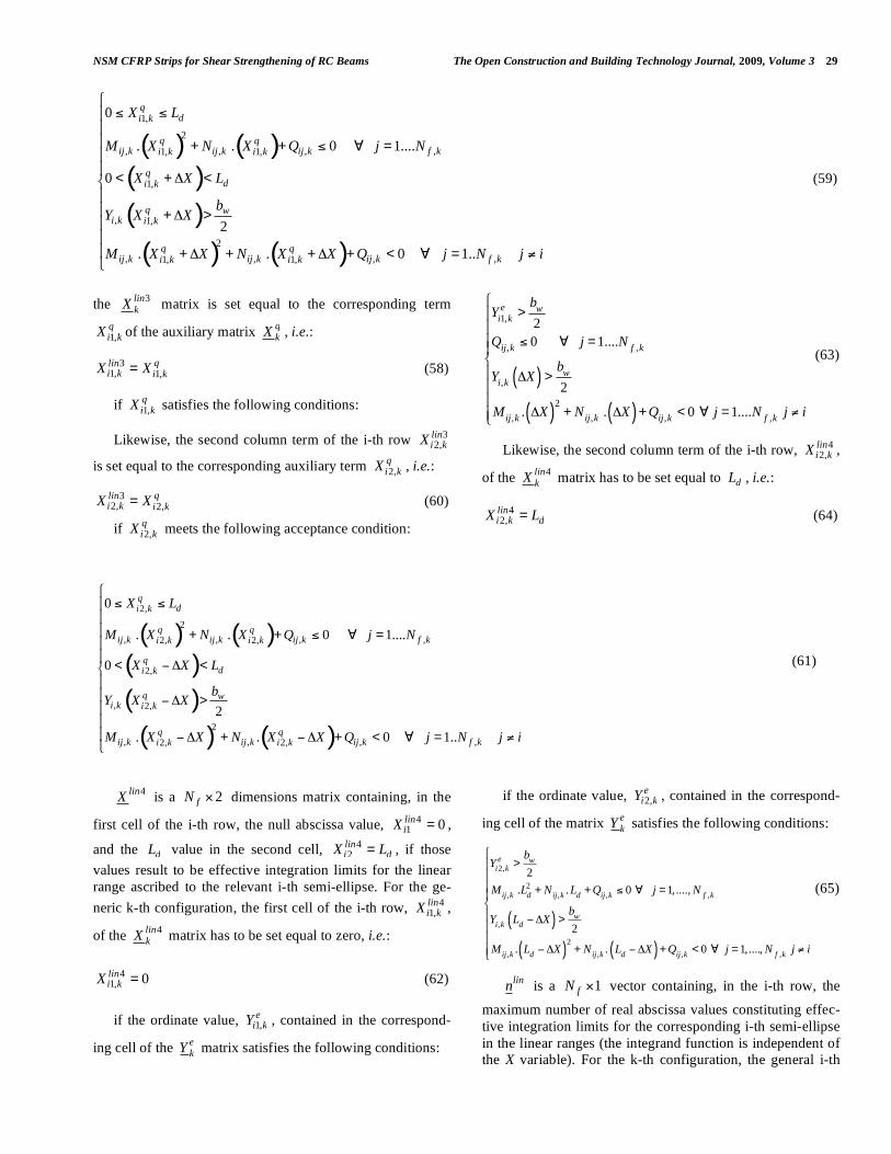
Determination of the Integration Points in the Linear Range lin
kX
linX is a linfN n! dimensions matrix containing, in the
i-th row, the couples of abscissa values constituting limits of the integration intervals, in correspondence of the i-th semi-ellipse, of the equation 2wY b= . For the generic k-th con-
figuration, the matrix linkX has ,
linf k kN n! dimensions where
linkn is the maximum number of real values of integration
limits amongst all the ,f kN semi-ellipses of that configura-
tion (an even number). To evaluate linkX , four other auxil-
iary matrices 1linkX , 2lin
kX , 3linkX , 4lin
kX have to be deter-
mined, based on the auxiliary ones 1pkX , 2p
kX , qkX , e
kY ,
kM , kN , k
Q , already built. 1linX and 2linX are two
f fN N! dimensions matrices containing, in the i-th row, the abscissa values, amongst those already calculated and stored in the corresponding i-th row of the auxiliary matrices
1pX and 2pX , respectively, that, according to the accep-tance conditions hereafter specified, effectively constitute useful integration limits for the linear range ascribed to the relevant i-th semi-ellipse. For the k-th configuration, the general j-th term 1/ 2
,linij kX of the i-th row of the 1/ 2lin
kX ma-
trix is set equal to the corresponding term 1/ 2,
pij kX of the cor-
responding auxiliary matrix 1/ 2pkX , i.e.:
1/ 21/ 2, ,
plinij k ij kX X= (56)
if 1/ 2,
pij kX is such as to satisfy, for the i-th semi-ellipse, the
following acceptance conditions:
0 < Xij,kp1/ 2 < Ld and Yi,k Xij,k
p1/ 2( ) >bw2
Mih,k . Xij,kp1/ 2( )
2+ Nih,k . Xij,k
p1/ 2( ) + Qih,k ! 0 for h = 1....N f ,k
0 < Xij,kp1/ 2 +"X( ) < Ld
Yi,k Xij,kp1/ 2 +"X( ) >
bw2
Mih,k . Xij,kp1/ 2 +"X( )
2+ Nih,k . Xij,k
p1/ 2 +"X( ) + Qih,k < 0 #h $ i
%
&
'''
(
'''
or
0 < Xij,kp1/ 2 ) "X( ) < Ld and
Yi,k Xij,kp1/ 2 ) "X( ) >
bw2
and
Mih,k . Xij,kp1/ 2 ) "X( )
2+ Nih,k . Xij,k
p1/ 2 ) "X( ) + Qih,k < 0#h $ i
%
&
'''
(
'''
%
&
''''''''
(
''''''''
Xij,kp1/ 2 $ Xig ,k
lin1/ 2 with g = 1,....., j )1( )
%
&
''''''''''''
(
''''''''''''
(57)
Note that 1/ 2,
pij kX in Eq. (57) represents the two possible
solutions, 1,
pij kX and 2
,pij kX . 3linX is a 2fN ! matrix con-
taining, in the first and second columns of the i-th row, 3
1liniX and 3
2liniX , respectively, the abscissa values of the left
and right intersection points of the relevant semi-ellipse with the straight line 2wY b= that result effective for the inte-gration of the corresponding equation 2wY b= . For the k-th
configuration, the first column term of the i-th row, 31,lini kX , of
Fig. (14). Determination of the effective matrix of the integration points in the non-linear range nlin
kX .
( )( ) ( )
( ) ( )
1 1
4 4 5 512 21 65 72
1 1
2 2 4 412 56 61
*
*
q p p qT o onlink p p q
o o d
X X X a X a X XX
X X a X a X X L
! "# #$ %=$ + + %& '
(55)
NSM CFRP Strips for Shear Strengthening of RC Beams The Open Construction and Building Technology Journal, 2009, Volume 3 29
the 3linkX matrix is set equal to the corresponding term
1,qi kX of the auxiliary matrix q
kX , i.e.:
31, 1,
qlini k i kX X= (58)
if 1,qi kX satisfies the following conditions:
Likewise, the second column term of the i-th row 32,lini kX
is set equal to the corresponding auxiliary term 2,qi kX , i.e.:
32, 2,
qlini k i kX X= (60)
if 2,qi kX meets the following acceptance condition:
4linX is a 2fN ! dimensions matrix containing, in the
first cell of the i-th row, the null abscissa value, 41 0liniX = ,
and the dL value in the second cell, 42lini dX L= , if those
values result to be effective integration limits for the linear range ascribed to the relevant i-th semi-ellipse. For the ge-neric k-th configuration, the first cell of the i-th row, 4
1,lini kX ,
of the 4linkX matrix has to be set equal to zero, i.e.:
41, 0lini kX = (62)
if the ordinate value, 1,e
i kY , contained in the correspond-
ing cell of the ekY matrix satisfies the following conditions:
Yi1,ke >
bw2
Qij,k ! 0 " j = 1....N f ,k
Yi,k #X( ) >bw2
Mij,k . #X( )2
+ Nij,k . #X( ) + Qij,k < 0 " j = 1....N f ,k j $ i
%
&
''''
(
''''
(63)
Likewise, the second column term of the i-th row, 42,lini kX ,
of the 4linkX matrix has to be set equal to dL , i.e.:
42,lini k dX L= (64)
if the ordinate value, 2,e
i kY , contained in the correspond-
ing cell of the matrix ekY satisfies the following conditions:
Yi2,ke >
bw2
Mij,k .Ld2 + Nij,k . Ld + Qij,k ! 0 " j = 1,...., N f ,k
Yi,k Ld # $X( ) >bw2
Mij,k . Ld # $X( )2
+ Nij,k . Ld # $X( ) + Qij,k < 0 " j = 1, ...., N f ,k j % i
&
'
((((
)
((((
(65)
linn is a 1fN ! vector containing, in the i-th row, the
maximum number of real abscissa values constituting effec-tive integration limits for the corresponding i-th semi-ellipse in the linear ranges (the integrand function is independent of the X variable). For the k-th configuration, the general i-th
( ) ( )
( )
( )
( ) ( )
1,
2, , , ,1, 1,
1,
, 1,
2, , , ,1, 1,
0
. . 0 1
0
2
. . 0 1..
qdi k
q qij k ij k ij k f ki k i k
qdi k
q wi k i k
q qij k ij k ij k f ki k i k
X L
M X N X Q j ....N
X X L
bY X X
M X X N X X Q j N j i
!" # #"" + + # $ =""
< + % <&""
+ % >""" + % + + % + < $ = '(
(59)
( ) ( )
( )
( )
( ) ( )
2,
2, , , ,2, 2,
2,
, 2,
2, , , ,2, 2,
0
. . 0 1
0
2
. . 0 1..
qdi k
q qij k ij k ij k f ki k i k
qdi k
q wi k i k
q qij k ij k ij k f ki k i k
X L
M X N X Q j ....N
X X L
bY X X
M X X N X X Q j N j i
!" # #"" + + # $ =""
< % & <'"" % & >""" % & + % & + < $ = ()
(61)
30 The Open Construction and Building Technology Journal, 2009, Volume 3 Barros et al.
term, ,lini kn , of the lin
kn vector is equal to the number of real values present amongst all the terms stored in the corre-sponding i-th row of all the auxiliary matrices, i.e.:
{ }1 2 3 4, , , , 1,real numbers ; ; ;lin lin lin lin lin
i k i k i k i k i kn X X X X= (66)
The number of columns of the linkX matrix, lin
kn , is equal to the maximum number of effective values among all the semi-ellipses for the k-th configuration, i.e.:
{ }, ,max with 1;...;lin link i k f kn n i N= = (67)
The linkX matrix is then built by joining, for each i-th
row corresponding to the i-th semi-ellipse, the effective terms, discarding the “non-values” present in the correspond-ing i-th row of the auxiliary matrices 1lin
kX , 2linkX , 3lin
kX , 4lin
kX , and sorting them in increasing order. For instance, the
transpose ( )Tlin
kX of the final matrix linkX for the example
of Fig. 11 is as follows (see also Fig. 15):
( )1
61 76
1
12 67 72
0 * * * *
* * * *
q pTlink q p q
X XX
X X X
! "= # $# $% &
(68)
Determination of the Areas k!
! is a 1fN ! dimension vector containing, in the i-th cell, the area ascribed to the i-th semi-ellipse. For the k-th configuration, the term ,i k! of the k! matrix is equal to:
, , ,nlin lin
i k i k i k! = ! +! (69)
where ,nlini k! is determined by the following equation:
For the sake of brevity, the expression of the exact inte-gration of the equation of the semi-ellipse is omitted but it
can be found elsewhere [5]. The term ,lini k! can be obtained
from:
( )
( ),2, 4,
1, 3, 1 ,
, . . ..... .2 2 2
linlinlin lin i n kki k i k
lin lin lini k i k lini n kk
XX X
lin w w wi k
X X X
b b bdX dX dX
! "#$ %& '
( = + +) ) ) (71)
Note that in the above Eqs. (70) and (71) the abscissa values, already stored in the corresponding i-th row of nlin
kX
and linkX , respectively, have to be considered integration
limits by pairs in sequence.
Determination of the Shear Strength Contributions pkV
and V
pV is a 1fN ! dimension vector containing, in the i-th
cell, the shear strength contribution ascribed to the i-th strip and parallel to its orientation. For the k-th configuration, the general i-th term, ,
pfi kV , of the p
kV vector is calculated by the following equation:
( ) ( ) ( ){ },, min 2 . . . ; . . ; . . sinpf f fi b fi f f fu i k ctmfi kV a b L L a b f f! " #= + $ +
( ) ( ) ( ){ },, min 2 . . . ; . . ; . . sinpf f fi b fi f f fu i k ctmfi kV a b L L a b f f! " #= + $ + (72)
V is a 1k ! dimension vector containing, in the k-th cell, the NSM shear strength contribution ,f kV corresponding to the k-th configuration. The k-th term is equal to:
,
, ,1
2 . sin .f kN
pf k fi k
i
V V!=
= " (73)
ASSESSMENT OF THE MODEL PERFORMANCE
The Proposed Model (PM) was used to predict the NSM contribution for the shear resistance of the beams of the ex-perimental program. The average tensile strength of the con-crete of the tested beams was estimated from the concrete average compressive strength at the age of the beam tests, and using the expressions proposed by the CEB-FIP model code 1993 [19], resulting ctmf = 2.45 MPa. The results are
Fig. (15). Determination of the effective matrix of the integration points in the linear range.
( ) ( ) ( )
( )
( ),2, 4,
1, 3, 1 ,
, , , ,. . ..... .
nlinnlinnlin nlin i n kki k i k
nlin nlin nlini k i k nlini n kk
XX X
nlini k i k i k i k
X X X
Y X dX Y X dX Y X dX
! "#$ %& '
( = + +) ) ) (70)
NSM CFRP Strips for Shear Strengthening of RC Beams The Open Construction and Building Technology Journal, 2009, Volume 3 31
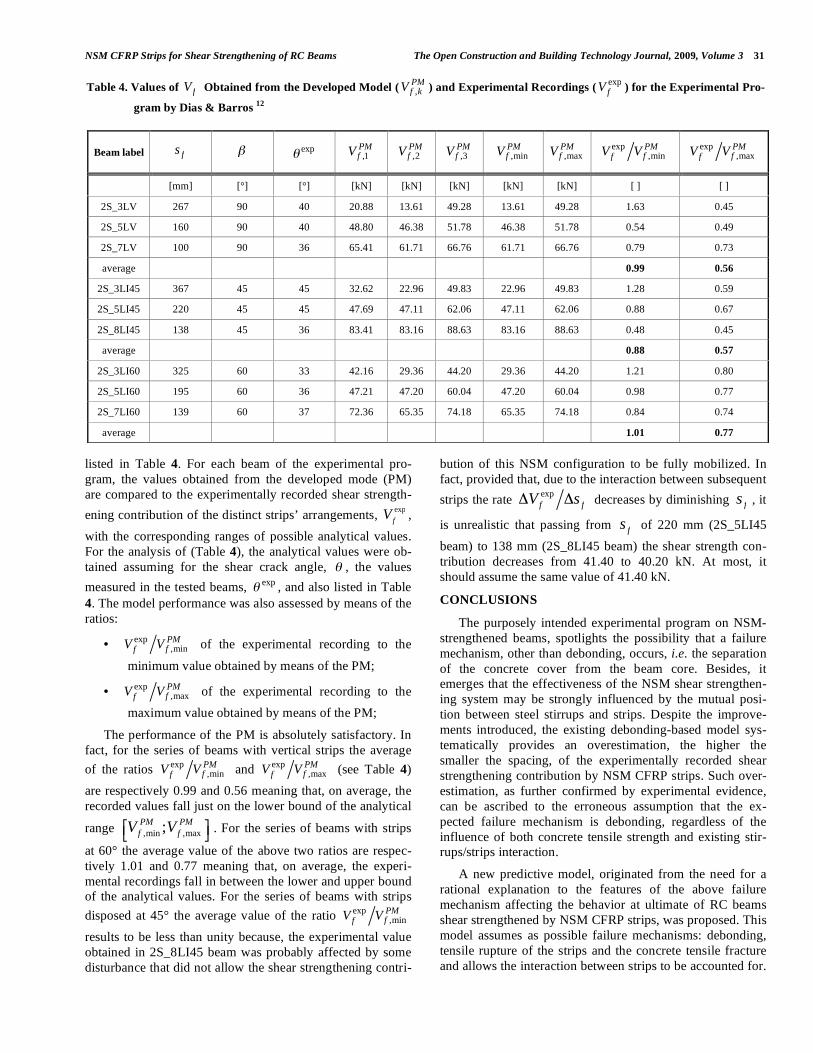
listed in Table 4. For each beam of the experimental pro-gram, the values obtained from the developed mode (PM) are compared to the experimentally recorded shear strength-ening contribution of the distinct strips’ arrangements, exp
fV , with the corresponding ranges of possible analytical values. For the analysis of (Table 4), the analytical values were ob-tained assuming for the shear crack angle, ! , the values measured in the tested beams, exp! , and also listed in Table 4. The model performance was also assessed by means of the ratios:
• exp,min
PMffV V of the experimental recording to the
minimum value obtained by means of the PM;
• exp,max
PMffV V of the experimental recording to the
maximum value obtained by means of the PM;
The performance of the PM is absolutely satisfactory. In fact, for the series of beams with vertical strips the average of the ratios exp
,minPMffV V and exp
,maxPMffV V (see Table 4)
are respectively 0.99 and 0.56 meaning that, on average, the recorded values fall just on the lower bound of the analytical
range ,min ,max;PM PMf fV V! "# $ . For the series of beams with strips
at 60° the average value of the above two ratios are respec-tively 1.01 and 0.77 meaning that, on average, the experi-mental recordings fall in between the lower and upper bound of the analytical values. For the series of beams with strips disposed at 45° the average value of the ratio exp
,minPMffV V
results to be less than unity because, the experimental value obtained in 2S_8LI45 beam was probably affected by some disturbance that did not allow the shear strengthening contri-
bution of this NSM configuration to be fully mobilized. In fact, provided that, due to the interaction between subsequent strips the rate exp
f fV s! ! decreases by diminishing fs , it
is unrealistic that passing from fs of 220 mm (2S_5LI45 beam) to 138 mm (2S_8LI45 beam) the shear strength con-tribution decreases from 41.40 to 40.20 kN. At most, it should assume the same value of 41.40 kN.
CONCLUSIONS
The purposely intended experimental program on NSM-strengthened beams, spotlights the possibility that a failure mechanism, other than debonding, occurs, i.e. the separation of the concrete cover from the beam core. Besides, it emerges that the effectiveness of the NSM shear strengthen-ing system may be strongly influenced by the mutual posi-tion between steel stirrups and strips. Despite the improve-ments introduced, the existing debonding-based model sys-tematically provides an overestimation, the higher the smaller the spacing, of the experimentally recorded shear strengthening contribution by NSM CFRP strips. Such over-estimation, as further confirmed by experimental evidence, can be ascribed to the erroneous assumption that the ex-pected failure mechanism is debonding, regardless of the influence of both concrete tensile strength and existing stir-rups/strips interaction.
A new predictive model, originated from the need for a rational explanation to the features of the above failure mechanism affecting the behavior at ultimate of RC beams shear strengthened by NSM CFRP strips, was proposed. This model assumes as possible failure mechanisms: debonding, tensile rupture of the strips and the concrete tensile fracture and allows the interaction between strips to be accounted for.
Table 4. Values of fV Obtained from the Developed Model ( ,PMf kV ) and Experimental Recordings ( exp
fV ) for the Experimental Pro-
gram by Dias & Barros 12
Beam label fs ! exp! ,1PMfV ,2
PMfV ,3
PMfV ,min
PMfV ,max
PMfV exp
,minPMffV V exp
,maxPMffV V
[mm] [°] [°] [kN] [kN] [kN] [kN] [kN] [ ] [ ]
2S_3LV 267 90 40 20.88 13.61 49.28 13.61 49.28 1.63 0.45
2S_5LV 160 90 40 48.80 46.38 51.78 46.38 51.78 0.54 0.49
2S_7LV 100 90 36 65.41 61.71 66.76 61.71 66.76 0.79 0.73
average 0.99 0.56
2S_3LI45 367 45 45 32.62 22.96 49.83 22.96 49.83 1.28 0.59
2S_5LI45 220 45 45 47.69 47.11 62.06 47.11 62.06 0.88 0.67
2S_8LI45 138 45 36 83.41 83.16 88.63 83.16 88.63 0.48 0.45
average 0.88 0.57
2S_3LI60 325 60 33 42.16 29.36 44.20 29.36 44.20 1.21 0.80
2S_5LI60 195 60 36 47.21 47.20 60.04 47.20 60.04 0.98 0.77
2S_7LI60 139 60 37 72.36 65.35 74.18 65.35 74.18 0.84 0.74
average 1.01 0.77
32 The Open Construction and Building Technology Journal, 2009, Volume 3 Barros et al.
The comparisons with the debonding-based model showed that the proposed model provided a better estimation of the experimentally recorded NSM shear strength contribution.
ACKNOWLEDGEMENTS
The authors of the present work wish to acknowledge the support provided by the “Empreiteiros Casais”, S&P, Secil (Unibetão, Braga) and Degussa Portugal. The study re-ported in this paper forms a part of the research program “SMARTREINFORCEMENT – Carbon fibre strips for the strengthening and monitoring of reinforced concrete struc-tures” supported by ADI-IDEIA, Project nº 13-05-04-FDR-00031. This work has been partially carried out under the program “Dipartimento di Protezione Civile – Consorzio RELUIS”, signed on 2005-07-11 (n. 540), Research Line 8, whose financial support is greatly appreciated.
REFERENCES [1] L. De Lorenzis, and A. Nanni, “Shear Strengthening of Reinforced
Concrete Beams with Near-Surface Mounted Fiber-Reinforced Polymer Rods”, ACI Structural Journal, Vol. 98(1), pp. 60-68, January-February 2001.
[2] R. El-Hacha, and S. H. Rizkalla, “Near-surface-mounted fiber-reinforced polymer reinforcements for flexural strengthening of concrete structures,” ACI Structural Journal, Vol. 101(5) pp. 717-726, 2004.
[3] J. A. O. Barros, and S. J. E. Dias, “Near surface mounted CFRP laminates for shear strengthening of concrete beams”, Journal of Cement and Concrete Composites, Vol. 28(3), pp. 276-292, 2006.
[4] A. Nanni, M. Di Ludovico, R. Parretti, “Shear strengthening of a PC bridge girder with NSM CFRP rectangular bars”, Advances in Structural Engineering, Vol. 7(4), pp. 97-109, 2004.
[5] V. Bianco, J. A. O. Barros, G. Monti, “Shear Strengthening of RC beams by means of NSM laminates: experimental evidence and predictive models”, Technical report 06-DEC/E-18, Dep. Civil Eng., School Eng. University of Minho, pp. 170, October 2006.
[6] S. J. E. Dias, J. A. O. Barros, “NSM CFRP Laminates for the Shear Strengthening of T Section RC Beams”, 2nd International fib Con-gress, Naples, 5-8 June 2006, Article 10-58 in CD.
[7] American Concrete Institute, Guide for the Design and Construc-tion of Externally Bonded FRP Systems for Strengthening Concrete Structures, ACI 440.2R-02, Farmington Hills, MI, 2002.
[8] J. M. Sena-Cruz, and J. A. O. Barros, “Bond between near-surface mounted CFRP laminate strips and concrete in structural strength-ening”, Journal of Composites for Construction, ASCE, Vol. 8(6), pp. 519-527, 2004.
[9] EN 206-1., “Concrete - Part 1: Specification, performance, produc-tion and conformity”, European standard, CEN, pp. 69, 2000.
[10] EN 10002., “Metallic materials -Tensile testing - Part 1: Method of test (at ambient temperature)”, p. 35, 1990.
[11] ISO 527-5., “Plastics - Determination of tensile properties - Part 5: Test conditions for unidirectional fiber-reinforced plastic compos-ites”, International Organization for Standardization, Genève, Switzerland, pp. 9, 1997.
[12] S. J. E. Dias, J. A. O. Barros, “CFRP no reforço ao corte de vigas de BA: investigação experimental e modelos analíticos (CFRP for the shear strengthening of RC beams: Experimental and analytical research)”, Technical Report 04-DEC/E-08, Dep. Civil Eng., School of Eng., University of Minho, May 2004, 108 pp. (in Portu-guese)
[13] R. A. Cook, G. T. Doerr, and R. E. Klingner, “Bond Stress Model for Design of Adhesive Anchors”, ACI Structural Journal, Vol. 90(5), pp.514-524, September-October 1993.
[14] R. A. Cook, A. Ronal, K. Jacob, F. Werner, R. Konz, C. Robert, “Behaviour and Design of Single Adhesive Anchors under Tensile Load in Uncracked Concrete”, ACI Structural Journal, Vol. 95(1), pp. 9-26, January/February 1998.
[15] R. A. Cook, and R., Konz, “Factors Influencing the Bond Strength of Adhesive Anchors,” ACI Structural Journal, American Concrete Institute (ACI), Vol. 98(1), pp. 76-86, January-February 2001.
[16] CEB bulletin d’information N° 233 “Design of Fastenings in Con-crete - Design Guide” - Parts 1 to 3, printed revised hardbound edi-tion of Bulletin 226 part 1, Telford, London, 1997; p. 83.
[17] J. M. Sena-Cruz, J. A. O. Barros, A. F. M. Azevedo, R. Gettu, “Bond behavior of near-surface mounted CFRP laminate strips un-der monotonic and cyclic loading”, Journal of Composites for Con-struction, ASCE, Vol. 10(4), pp. 295-303, 2006.
[18] J.G. Teng, L. De Lorenzis, B. Wong, R. Li, T.N. Wang, L. Lam, “Debonding failures of RC Beams Strengthened with Near Surface Mounted CFRP Strips”, Journal of Composites for Construction, ACSE, Vol. 10(2), pp. 92-105, March-April 2006.
[19] CEB-FIP, Model Code 1990, Comite Euro-International du Beton, Bulletin d’Information nº 213/214, T. Telford, Ed., London, 1993.
Received: August 28, 2008 Revised: October 09, 2008 Accepted: October 09, 2008
© Barros et al.; Licensee Bentham Open.
This is an open access article licensed under the terms of the Creative Commons Attribution Non-Commercial License (http://creativecommons.org/-licenses/by-nc/3.0/) which permits unrestricted, non-commercial use, distribution and reproduction in any medium, provided the work is properly cited.
Related Documents


