--.__I...-.“i-----m....-. “-1__._~-“-- -. (;A0 /‘NSIAI)-!)I-:I()!)

Welcome message from author
This document is posted to help you gain knowledge. Please leave a comment to let me know what you think about it! Share it to your friends and learn new things together.
Transcript
--.__I...-.“i-----m....-. “-1__._~-“-- -.
(;A0 /‘NSIAI)-!)I-:I()!)
“ “ l l l _ . . “ . “ l ~ - - - l . l ~ “ . _ ~ ~ - - - - - - - - - . - -
GAO United States General Accounting Office Washington, D.C. 20548
National Security and International Ai’fairs Division
B-246447
September 30,199 1
The Honorable Nicholas Mavroules Chairman, Subcommittee on Investigations Committee on Armed Services House of Representatives
Dear Mr. Chairman:
This report responds to your January 11,1991, request that we review the basis for the Air Force’s decision to change military specifications for class 3 threaded fasteners’ and the scope and methodology of its estimate of the cost to implement the changes.
Background Currently, three separate sets of standards exist for threaded fasteners manufactured in the United States. These standards include military specifications issued by the Air Force for the Department of Defense and the military services.2 Other specifications are federal standards prepared by the Defense Industrial Supply Center (on behalf of the Department of Commerce) and national standards issued by the Amer- ican National Standards Institute (under sponsorship from the American Society of Mechanical Engineers). The military specifications for class 3 fasteners were issued in 1966 and revised in 1973.
The military specifications describe the thread characteristics (see app. I) and the inspection methods required for verification and acceptance of fasteners and other threaded products by the ordering service. The specifications require certain inspections to be conducted by the manu- facturer. Three methods (A, B, and C), which differ in rigorousness, are used for verifying that fasteners meet specifications. These methods are identical to those specified in both the federal and national standards.
‘A class 3 threaded fastener typically refers to nuts and bolts used in aerospace and other high- technology applications, but it also refers to any high-technology threaded product, such as a threaded engine drive shaft. Class 3 fasteners are used in critical applications (those in which thread failure would cause a catastrophic accident) and are manufactured to stringent standards for strength and integrity.
‘MILS7742, Screw Threads, Standard, Optimum Selected Series: General Specification for, and MILS8879, Screw Threads, Controlled Radius Root With Increased Minor Diameter: General Specifi- cations for.
Page 1 GAO/N&W-91-909 Fastener SpecifIcationa
B245447
Method A inspection is a functional test to determine if the fastener will assemble with a standard thread. Method B inspection includes the func- tional test required in method A inspection and the measurement of up to four other thread characteristics. Method C inspection includes the measurement of the thread characteristics required by method B inspec- tion and the measurement of six additional thread characteristics. The current specifications prescribe method A inspection for internally threaded fasteners and method B inspection for externally threaded fas- teners.” The proposed specifications include a default4 clause that speci- fies the application category and the thread characteristics to be inspected to ensure thread conformance.
The Air Force is the Department of Defense’s executive agent for class 3 threaded fasteners. In 1987 the Air Force changed its own inspection and acceptance policy for class 3 fasteners and in 1988 issued interim specifications, which may be used in acquisition of military hardware. These changes established a safety-critical category of fasteners for which thread failure would result in loss of life, serious injury, or loss of a major weapon system. The changes also eliminated method A inspection.
The proposed specifications would require, as a default, the equivalent of method C inspection for all safety-critical fasteners and method B inspection for all other fasteners. Method B inspection could be con- ducted on a sample of fasteners from a manufacturing lot. Safety-crit- ical fasteners must receive loo-percent inspection or be produced from a government-approved on-line process control (special measurements taken during the actual production of fasteners to help control manufac- turing quality). The thread characteristics detailed in the existing speci- fications would not change.
During the past several years, the Air Force has been in the process of changing the final specifications, but it has met strong opposition from groups in the fastener and aerospace industries who claim that the changes are unnecessary and will not improve the quality of the product. As we reported earlier,6 the Air Force has followed applicable
“Internal threads are used on nuts, and external threads are used on bolts.
4A default occurs when the manufacturer does not specify the application category and/or the thread characteristics to be inspected. When this happens, the specifications prescribe what should be done.
“DOD Procurement: Changes to Military Specifications for Testing InduStI’idl Fasteners (GAO/ 1 - - 84, Dec. 21, 1990).
Page 2 GAO/NSIAD-91-309 Fastener Specifications
Results in Brief
regulations for changing specifications. Each of the other military ser- vices has concurred with the technical merits of the changes, and the Air Force prepared an analysis of the cost impact of the proposed changes.
The Air Force’s decision to change the specifications, in our opinion, is reasonable, and the specifications should be implemented. The Air Force had evidence indicating that deficiencies in the specifications contrib- uted to fatal accidents and other incidents that affected the perform- ance of military hardware. The Air Force also had evidence that a substantial number of fasteners in the Department of Defense’s inven- tory did not conform to the requirements of existing specifications. The Air Force attributed this problem to a lack of quality control during manufacture and the inadequacy of inspection methods prescribed by the specifications.
Groups representing the fastener and aerospace industries claimed that poor enforcement of the current specifications by the Department of Defense was the cause of the accidents and the nonconforming invento- ries. Evidence we examined corroborated that existing inspection speci- fications are fundamentally flawed. As stated by the Air Force and the National Institute of Standards and Technology, method A inspection accepts products that do not conform to existing specifications and thus have less strength and integrity than products that meet specifications. Moreover, method B inspection provides insufficient information about the adequacy of safety-critical fasteners. The proposed specifications appropriately require more rigorous inspections for safety-critical fasteners.
Although industry groups also claimed that measuring gages needed to perform the proposed inspections were not sufficiently accurate, evi- dence we examined indicated that measuring gages do exist to perform these inspections with sufficient accuracy and reliability.
The Air Force estimated that government and industry would incur only modest costs in implementing the proposed specification changes. Sev- eral industry groups estimated that the costs would be substantially higher than the Air Force predicted. We were unable to determine the most accurate estimate because factors were omitted, inappropriately included, or insufficiently supported in both the Air Force and industry estimates.
Page 3 GAO/NSIAD91-309 Fastener Specifications
B-245447
Evidence of Need to The evidence we examined included the accidents and failures cited by
Change Specifications the Air Force and the nonconforming threaded products found in the government’s inventory. The accidents and failures and the noncon- forming inventory are discussed below and in more detail in appendixes II and III, respectively.
Accidents and Failures The Air Force has repeatedly stated that safety concerns are the moti- vation for the proposed specifications. The Air Force recently cited two fatal accidents as the primary reason for the proposed specifications. The accidents cited are an Army UH-6OA Blackhawk helicopter crash and an Air Force CHSE helicopter crash, resulting in 9 and 15 fatalities, respectively. In both of these accidents, failure of nonconforming threaded parts caused the helicopters’ rotor blades to separate from the main rotor heads. The Blackhawk parts were found acceptable by the manufacturer to existing inspection requirements (method A inspection for internal threads and method B inspection for external threads). Non- conforming supply parts identical to the part that failed on the CHSE also passed method A inspection.
Two other equipment failures were cited by the Air Force to justify the changes. One failure involved engines of Navy F-14 aircraft, and the other involved nuts and bolts used on Navy nuclear submarines. In both of these failures, the inferior threads were found to be acceptable under method A inspection.
Nonconforming Products in Inventory
Several inspections since October 1986 of threaded products accepted in the Department of Defense’s inventory have disclosed that over 60 per- cent did not conform to specifications. The Air Force concluded from the reviews that nonconforming products were being accepted into the b inventory because the existing specifications allowed many items to be accepted by method A testing. The National Aeronautics and Space Administration also found high percentages of nonconforming products in the inventory of one of its space centers.
Accuracy of Indicating Measuring gages are used to determine if the fastener’s threads meet
Gage Measurements ”
specification requirements. Manufacturers and suppliers frequently use indicating measuring gages when performing method B and C inspec- tions. Indicating gages measure actual dimensions of individual thread characteristics. Industry groups expressed concerns about the proper calibration and the accuracy of these gages (see app. IV). However,
Page 4 GAO/NSLAD-91309 Fastener Specifications
B-246447
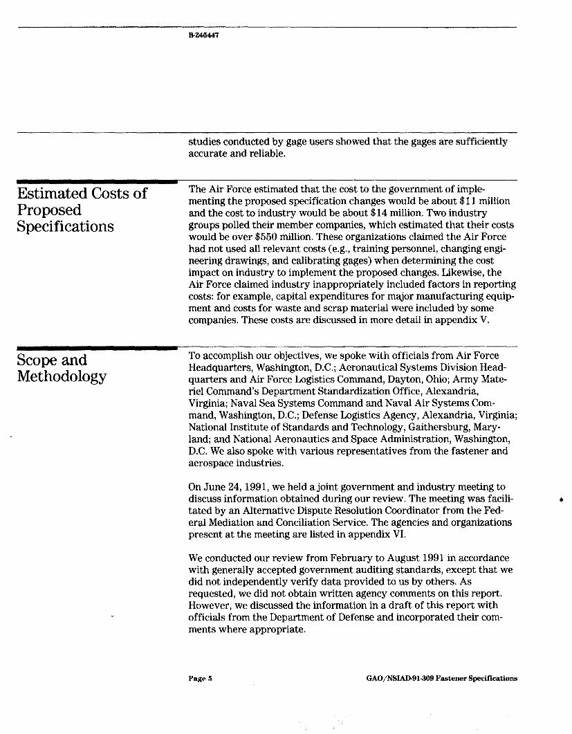
studies conducted by gage users showed that the gages are sufficiently accurate and reliable.
Estimated Costs of Proposed Specifications
The Air Force estimated that the cost to the government of imple- menting the proposed specification changes would be about $11 million and the cost to industry would be about $14 million. Two industry groups polled their member companies, which estimated that their costs would be over $550 million, These organizations claimed the Air Force had not used all relevant costs (e.g., training personnel, changing engi- neering drawings, and calibrating gages) when determining the cost impact on industry to implement the proposed changes. Likewise, the Air Force claimed industry inappropriately included factors in reporting costs: for example, capital expenditures for major manufacturing equip- ment and costs for waste and scrap material were included by some companies, These costs are discussed in more detail in appendix V.
Scope and Methodology
To accomplish our objectives, we spoke with officials from Air Force Headquarters, Washington, D.C.; Aeronautical Systems Division Head- quarters and Air Force Logistics Command, Dayton, Ohio; Army Mate- riel Command’s Department Standardization Office, Alexandria, Virginia; Naval Sea Systems Command and Naval Air Systems Com- mand, Washington, D.C.; Defense Logistics Agency, Alexandria, Virginia; National Institute of Standards and Technology, Gaithersburg, Mary- land; and National Aeronautics and Space Administration, Washington, DC. We also spoke with various representatives from the fastener and aerospace industries.
On June 24,1991, we held a joint government and industry meeting to discuss information obtained during our review. The meeting was facili- tated by an Alternative Dispute Resolution Coordinator from the Fed- eral Mediation and Conciliation Service. The agencies and organizations present at the meeting are listed in appendix VI.
We conducted our review from February to August 1991 in accordance with generally accepted government auditing standards, except that we did not independently verify data provided to us by others. As requested, we did not obtain written agency comments on this report. However, we discussed the information in a draft of this report with officials from the Department of Defense and incorporated their com- ments where appropriate.
Page 5 GAO/NSIAD-91-309 Fastener Specifications
B-246447
We are sending copies of this report to the Chairmen, House and Senate Committees on Armed Services; the Secretaries of Defense, the Army, the Navy, and the Air Force; the Director, Office of Management and Budget; and other interested parties. We will also make copies available to others on request.
Please contact me at (202) 275-4268 if you or your staff have any ques- tions concerning this report. Major contributors to this report are listed in appendix VII.
Sincerely yours,
Nancy R. Kingsbury I
Director fl Air Force Issues
Page 6 GAO/NSIAD-91-909 Fastener Specificationa
Page 7 GAO/NSIAD81-309 Fastener Specifications
,‘.i I
‘” ,,
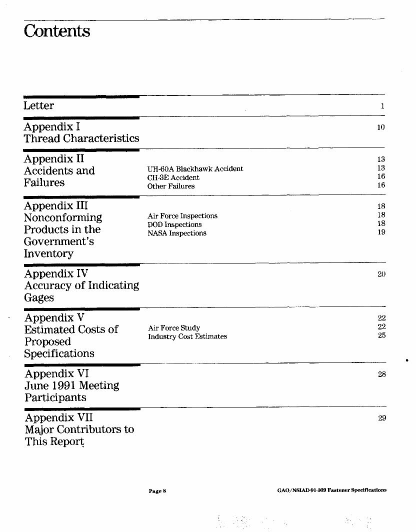
Letter
Appendix I Thread Characteristics
Appendix II Accidents and Failures
UH-6OA Blackhawk Accident CHSE Accident Other Failures
13 13 16 16
Appendix III Nonconforming Products in the Government’s Inventory
Air Force Inspections DOD Inspections NASA Inspections
18 18 18 19
Appendix IV Accuracy of Indicating Gages
20
Appendix V Estimated Costs of Proposed Specifications
Appendix VI June 1991 Meeting Participants
Air Force Study Industry Cost Estimates
22 22 26
6 28
Appendix VII Major Contributors to This Report
29
Page 8 GAO/NSIAD-91-309 Fastener Specifications
.
Contents
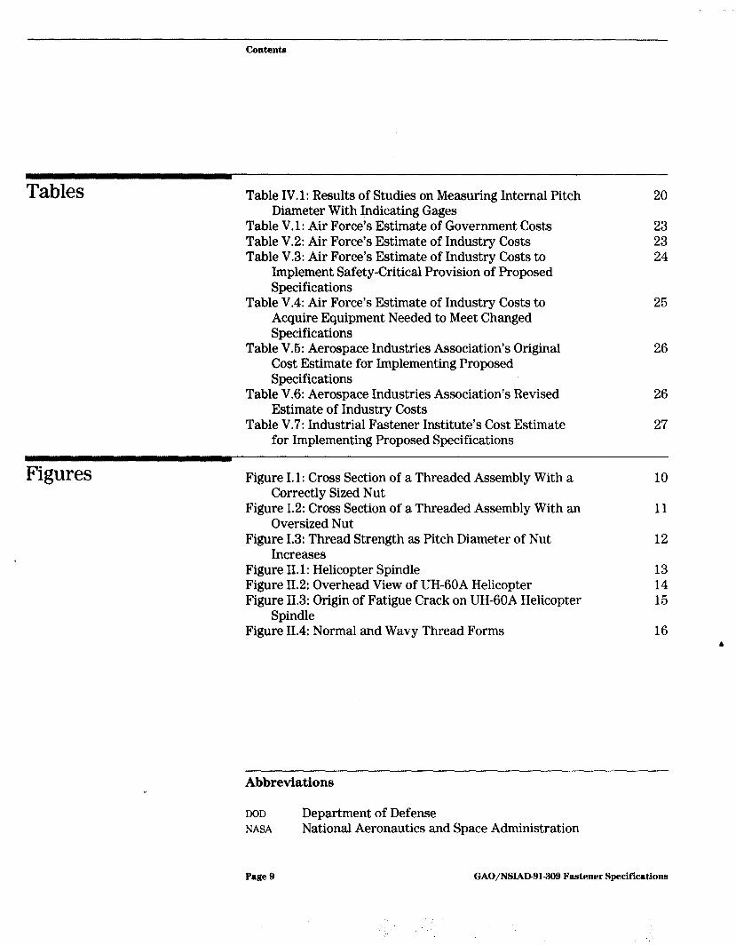
Tables Table IV. 1: Results of Studies on Measuring Internal Pitch Diameter With Indicating Gages
Table V-1: Air Force’s Estimate of Government Costs Table V.2: Air Force’s Estimate of Industry Costs Table V.3: Air Force’s Estimate of Industry Costs to
Implement Safety-Critical Provision of Proposed Specifications
Table V.4: Air Force’s Estimate of Industry Costs to Acquire Equipment Needed to Meet Changed Specifications
Table V.6: Aerospace Industries Association’s Original Cost Estimate for Implementing Proposed Specifications
Table V.6: Aerospace Industries Association’s Revised Estimate of Industry Costs
Table V-7: Industrial Fastener Institute’s Cost Estimate for Implementing Proposed Specifications
Figures Figure I. 1: Cross Section of a Threaded Assembly With a Correctly Sized Nut
10
Figure 1.2: Cross Section of a Threaded Assembly With an Oversized Nut
11
Figure 1.3: Thread Strength as Pitch Diameter of Nut Increases
12
Figure II. 1: Helicopter Spindle 13 Figure 11.2: Overhead View of UH-6OA Helicopter 14 Figure 11.3: Origin of Fatigue Crack on UH-6OA Helicopter 15
Spindle Figure 11.4: Normal and Wavy Thread Forms 16
20
23 23 24
25
26
26
27
Abbreviations
DOD Department of Defense NASA National Aeronautics and Space Administration
Page 9 GAO/NSJAD-91.309 Fastener Specifications
Appendix I
Thread Characteristics
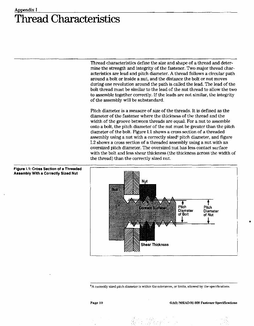
Thread characteristics define the size and shape of a thread and deter- mine the strength and integrity of the fastener. Two major thread char- acteristics are lead and pitch diameter. A thread follows a circular path around a bolt or inside a nut, and the distance the bolt or nut moves during one revolution around the path is called the lead. The lead of the bolt thread must be similar to the lead of the nut thread to allow the two to assemble together correctly. If the leads are not similar, the integrity of the assembly will be substandard.
Pitch diameter is a measure of size of the threads. It is defined as the diameter of the fastener where the thickness of the thread and the width of the groove between threads are equal, For a nut to assemble onto a bolt, the pitch diameter of the nut must be greater than the pitch diameter of the bolt. Figure I.1 shows a cross section of a threaded assembly using a nut with a correctly sized6 pitch diameter, and figure I.2 shows a cross section of a threaded assembly using a nut with an oversized pitch diameter. The oversized nut has less contact surface with the bolt and less shear thickness (the thickness across the width of the thread) than the correctly sized nut.
Figure 1.1: Cross Section of a Threaded Assembly With a Correctly Sized Nut
-f Pitch Diameter of Nut
“A correctly sized pitch diameter is within the tolerances, or limits, allowed by the specifications.
Page 10 GAO/NSIAD-91-399 Fastener Specifications

Appendix I Thread Characteristics
Figure 1.2: Croea Section of a Threaded Aeeembly With an Oversized Nut
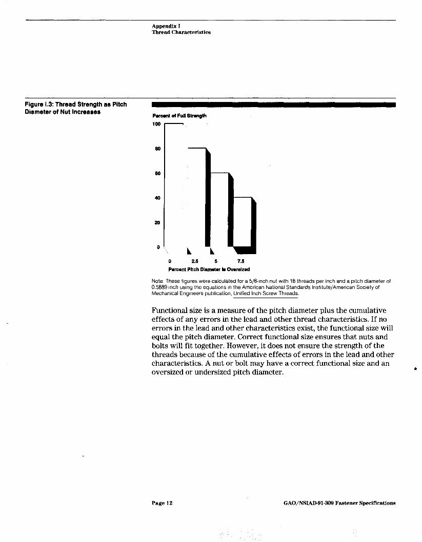
Pitch diameter sizes of the nut and bolt are used to calculate the strength of a threaded assembly. The strongest assembly occurs when the pitch diameter of the nut is slightly larger than the pitch diameter of the bolt. As the pitch diameter of the nut increases, or the pitch diam- eter of the bolt decreases, the strength of the joint decreases. For example, a 5/84nch nut oversized by 5 percent will have only 60 percent of the strength of a correctly sized nut. Figure I.3 shows how rapidly strength decreases when pitch diameter deviates from the correct size.
Page 11 GAO/NSIAD-91-309 Fastener Specifications
Appendix I Thread Characteristics
Figure 1.3: thread Strength as Pitch Diameter of Nut lncrearer
Poroont ot Full Stmgth 100
so
so
40
20
0
0 2.6 5 7.6 Porcsnt Pitch Dlametw Is Oversized
Note: These figures were calculated for a 5/8-inch nut with 18 threads per inch and a pitch diameter of 0.5889 inch using the equations in the American National Standards institute/American Society of Mechanical Engineers publication, Unified Inch Screw Threads.
Functional size is a measure of the pitch diameter plus the cumulative effects of any errors in the lead and other thread characteristics. If no errors in the lead and other characteristics exist, the functional size will equal the pitch diameter. Correct functional size ensures that nuts and bolts will fit together. However, it does not ensure the strength of the threads because of the cumulative effects of errors in the lead and other characteristics. A nut or bolt may have a correct functional size and an oversized or undersized pitch diameter. 6
Page 12 GAO/NSIAD-91-309 Fastener Specifications
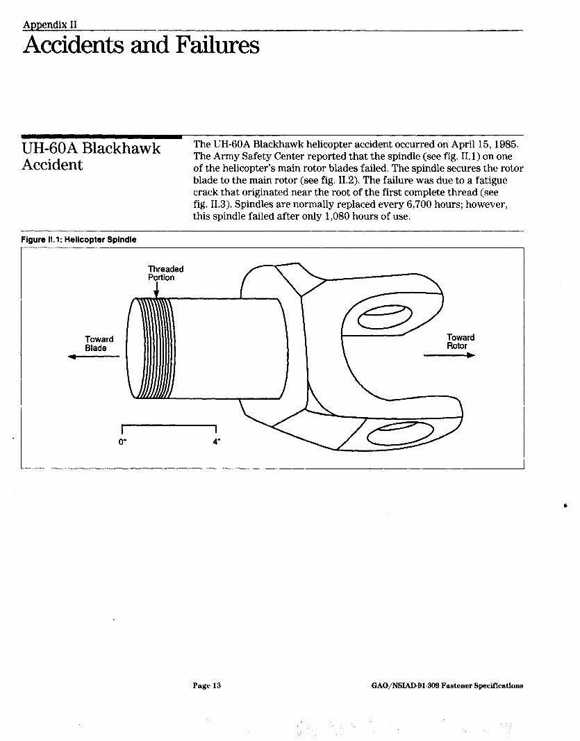
UH-60A Blackhawk The UH-6OA Blackhawk helicopter accident occurred on April 15, 1985.
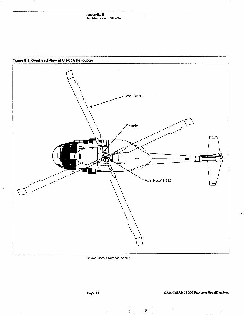
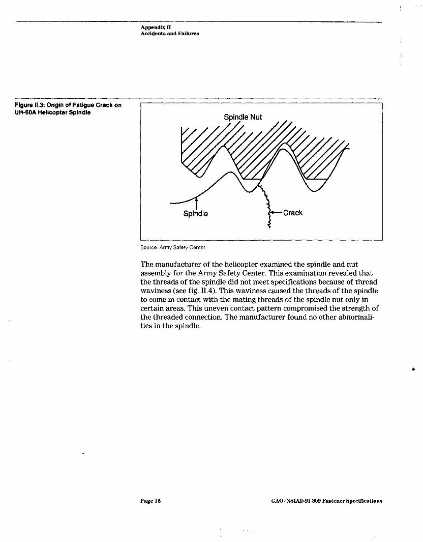
Accident The Army Safety Center reported that the spindle (see fig. II. 1) on one of the helicopter’s main rotor blades failed. The spindle secures the rotor blade to the main rotor (see fig. 11.2). The failure was due to a fatigue crack that originated near the root of the first complete thread (see fig. 11.3). Spindles are normally replaced every 6,700 hours; however, this spindle failed after only 1,080 hours of use.
Figure 11.1: Helicopter Spindle
Page 13 GAO/NSLkD-91-309 Fastener Specifications
Appendix II Accidents and Failures
Fiaure 11.2: Overhead View of UH-6OA HellcorM
Source: Jane’s Defence Weekly
Y
Page 14 GAO/NSIAD-91-309 Fastener Specifications
Appendix II Accidents and Failures
Figure 11.3: Origin of Fatigue Crack on UH-60A Helicopter Spindle
Source: Army Safety Center
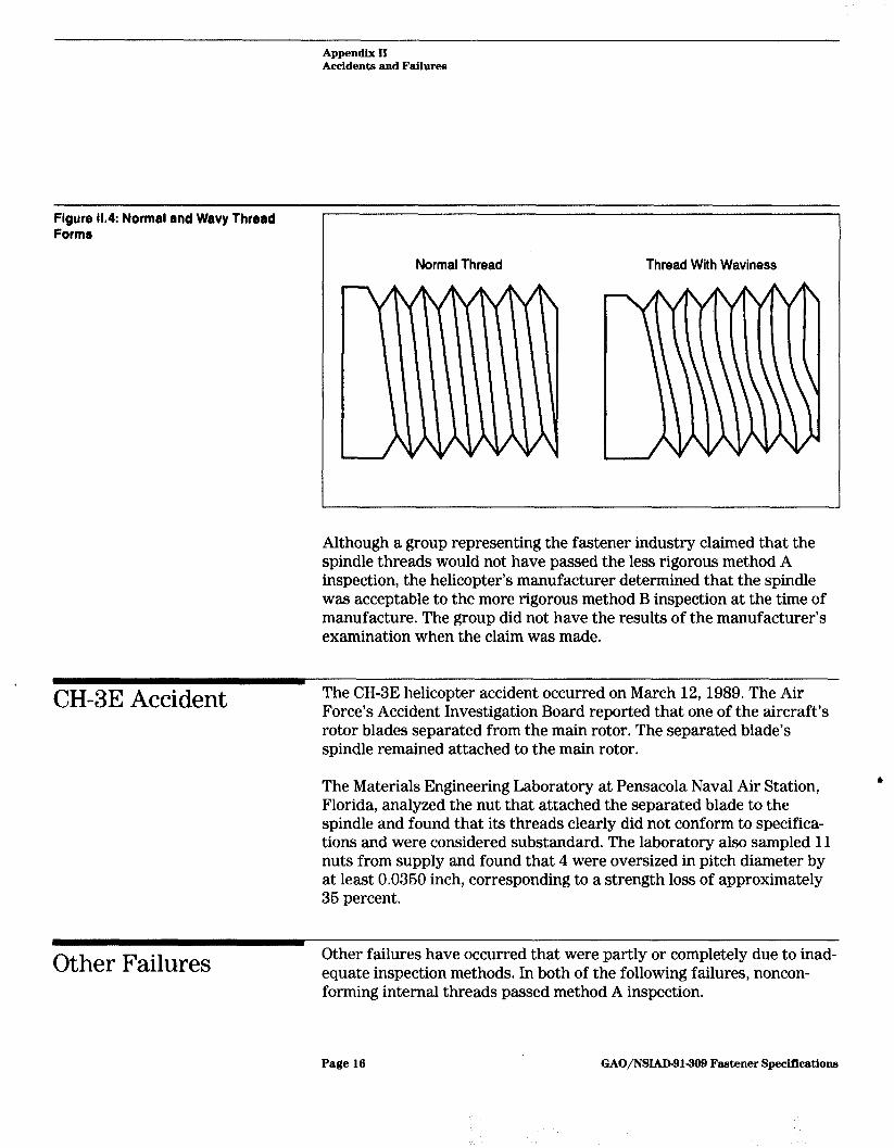
The manufacturer of the helicopter examined the spindle and nut assembly for the Army Safety Center. This examination revealed that the threads of the spindle did not meet specifications because of thread waviness (see fig. 11.4). This waviness caused the threads of the spindle to come in contact with the mating threads of the spindle nut only in certain areas. This uneven contact pattern compromised the strength of the threaded connection. The manufacturer found no other abnormali- ties in the spindle.
Page 16 GAO/NSIAD-91309 Fastener Specifications
Appendix II Accidents and Failures
Figure 11.4: Normal and Wavy Thread Forms
Normal Thread Thread With Waviness
Although a group representing the fastener industry claimed that the spindle threads would not have passed the less rigorous method A inspection, the helicopter’s manufacturer determined that the spindle was acceptable to the more rigorous method B inspection at the time of manufacture. The group did not have the results of the manufacturer’s examination when the claim was made.
CH-3E Accident The CHSE helicopter accident occurred on March 12, 1989. The Air Force’s Accident Investigation Board reported that one of the aircraft’s rotor blades separated from the main rotor. The separated blade’s spindle remained attached to the main rotor.
The Materials Engineering Laboratory at Pensacola Naval Air Station, 8
Florida, analyzed the nut that attached the separated blade to the spindle and found that its threads clearly did not conform to specifica- tions and were considered substandard. The laboratory also sampled 11 nuts from supply and found that 4 were oversized in pitch diameter by at least 0.0360 inch, corresponding to a strength loss of approximately 36 percent.
Other Failures Other failures have occurred that were partly or completely due to inad- equate inspection methods. In both of the following failures, noncon- forming internal threads passed method A inspection.
Page 16 GAO/NSIAD-91-309 Fastener Specifications
Appendix II Accidenb and FuUures
The Naval Air Rework Facility at Norfolk, Virginia, determined that excess vibration on many TF-30 engines it tested was due to noncon- forming pitch diameters of the internal threads on the engine’s sealing tubes. The TF-30 engines, used to power Navy F-14 aircraft, were rejected after overhaul because of excess vibration.
The engine manufacturer attributed the nonconforming threads to the fact that fixed limit gages (see app. IV) cannot properly and consistently identify all thread element nonconformances. Subsequently, the Navy incorporated an inspection program using indicating gages on all over- hauled TF-30 engine sealing tubes. This inspection program lowered the engine rejection rate due to vibration from 13.6 to 5.8 percent, repre- senting a $290,000 estimated savings for the first year. The engine’s manufacturer now requires that suppliers of the sealing tubes conduct inspections using indicating gages.
In another example, corrosion-resistant nuts and bolts used on nuclear submarines failed on installation. The Norfolk Naval Shipyard examined a sample of the failed nuts and found that all had nonconforming threads with pitch diameters outside the allowable specification limits. All of the nuts passed method A inspection. A shipyard official told us that although the absence of lubrication in the threaded assembly was the primary cause of the failures, the oversized condition of the nuts exacerbated the failures. To help prevent further failures, the shipyard alerted other submarine shipyards using these nuts to measure the pitch diameter of internal threads in critical applications.
Page 17 GAO/NSIAD-91-309 Fastener Specifications
:.
Appendix III
Nonconforming Products in the Gwernment’s Inventory
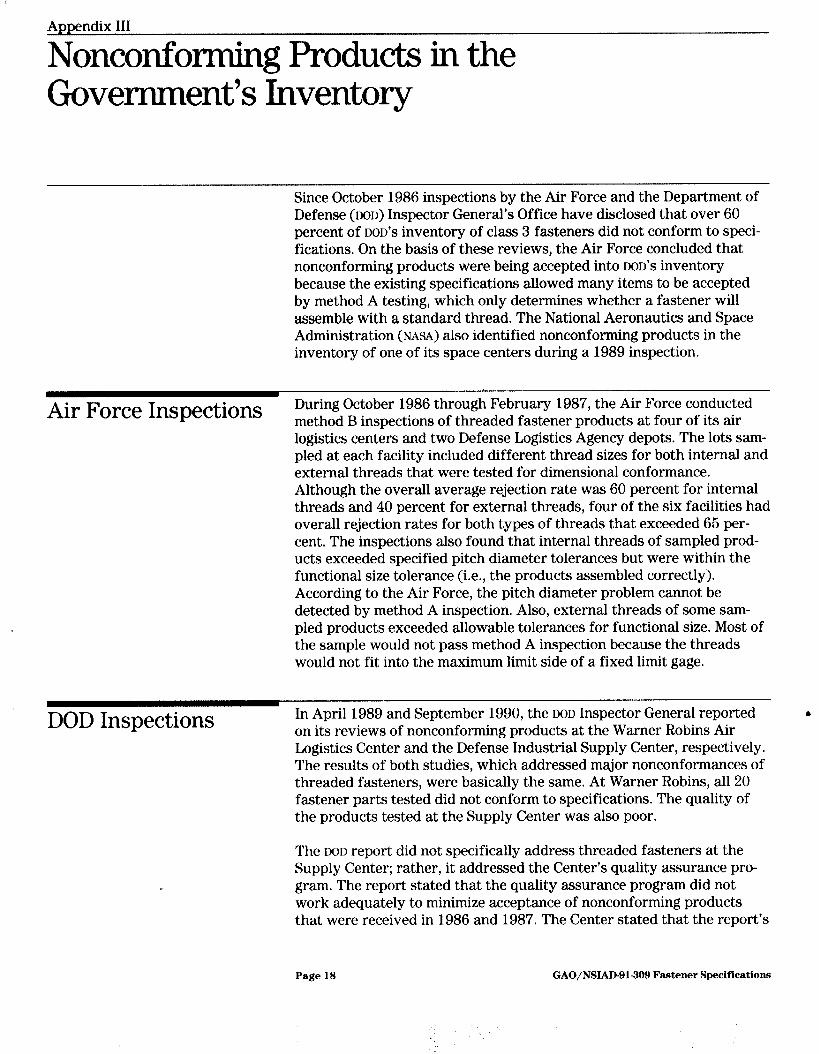
Since October 1986 inspections by the Air Force and the Department of Defense (DOD) Inspector General’s Office have disclosed that over 60 percent of DOD'S inventory of class 3 fasteners did not conform to speci- fications. On the basis of these reviews, the Air Force concluded that nonconforming products were being accepted into DOD'S inventory because the existing specifications allowed many items to be accepted by method A testing, which only determines whether a fastener will assemble with a standard thread. The National Aeronautics and Space Administration (NASA) also identified nonconforming products in the inventory of one of its space centers during a 1989 inspection.
Air Force Inspections During October 1986 through February 1987, the Air Force conducted method B inspections of threaded fastener products at four of its air logistics centers and two Defense Logistics Agency depots. The lots sam- pled at each facility included different thread sizes for both internal and external threads that were tested for dimensional conformance. Although the overall average rejection rate was 60 percent for internal threads and 40 percent for external threads, four of the six facilities had overall rejection rates for both types of threads that exceeded 65 per- cent. The inspections also found that internal threads of sampled prod- ucts exceeded specified pitch diameter tolerances but were within the functional size tolerance (i.e., the products assembled correctly). According to the Air Force, the pitch diameter problem cannot be detected by method A inspection. Also, external threads of some sam- pled products exceeded allowable tolerances for functional size. Most of the sample would not pass method A inspection because the threads would not fit into the maximum limit side of a fixed limit gage.
DOD Inspections In April 1989 and September 1990, the DOD Inspector General reported 8 on its reviews of nonconforming products at the Warner Robins Air Logistics Center and the Defense Industrial Supply Center, respectively. The results of both studies, which addressed major nonconformances of threaded fasteners, were basically the same. At Warner Robins, all 20 fastener parts tested did not conform to specifications. The quality of the products tested at the Supply Center was also poor.
The DOD report did not specifically address threaded fasteners at the Supply Center; rather, it addressed the Center’s quality assurance pro- gram. The report stated that the quality assurance program did not work adequately to minimize acceptance of nonconforming products that were received in 1986 and 1987. The Center stated that the report’s
Page 18 GAO/NSIAD-91-309 Fastener Specifications

Appendix III Nonconforming Products in the Government’s Inventory
NASA Inspections In May 1989 NASA, with the support of its contractors, inspected 11 dif- ferent sizes of flight-critical class 3 fasteners at the Kennedy Space Center for thread compliance. NASA inspected 1,077 external fasteners and 666 internal fasteners. The inspection revealed that approximately 72 percent of the external fasteners and 66 percent of the internal fas- teners did not conform to specifications. NASA contractors reinspected 180 of the fasteners and found that 27.5 percent still did not conform to specifications, As a result of these inspections, the Center’s Director of Safety, Reliability, and Quality Assurance issued an interim policy that all class 3 threaded fasteners with flight-critical applications be inspected.
finding was based on contracts awarded before it took corrective actions once it discovered fastener fraud and nonconformances in its inventory. The corrective actions the Center took included
installing thread measurement equipment (indicating gages) at depots receiving class 3 fasteners; incorporating a traceability requirement using manufacturing insignias or logos; instituting product verification testing before acceptance and shipment to depots; incorporating a certificate of quality compliance, which requires actual test and inspection data to support certification that a product meets requirements; and pursuing legal action against manufacturers and individuals.
The Center reported that, as a result of its corrective actions, the non- conformance rate for class 3 fasteners has decreased from 45 to 3.5 per- cent, approximately $2.9 million has been recovered, and 19 individuals have been convicted of fraud and 45 companies or individuals have been disbarred.
Page 19 GAO/NSIAD-91-309 Fastener Specifications
Appendix IV
Accuracy of Indicating Gages
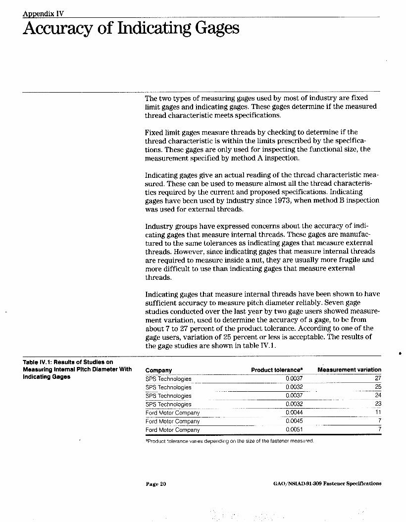
The two types of measuring gages used by most of industry are fixed limit gages and indicating gages. These gages determine if the measured thread characteristic meets specifications.
Fixed limit gages measure threads by checking to determine if the thread characteristic is within the limits prescribed by the specifica- tions, These gages are only used for inspecting the functional size, the measurement specified by method A inspection.
Indicating gages give an actual reading of the thread characteristic mea- sured. These can be used to measure almost all the thread characteris- tics required by the current and proposed specifications. Indicating gages have been used by industry since 1973, when method B inspection was used for external threads.
Industry groups have expressed concerns about the accuracy of indi- cating gages that measure internal threads. These gages are manufac- tured to the same tolerances as indicating gages that measure external threads. However, since indicating gages that measure internal threads are required to measure inside a nut, they are usually more fragile and more difficult to use than indicating gages that measure external threads.
Indicating gages that measure internal threads have been shown to have sufficient accuracy to measure pitch diameter reliably. Seven gage studies conducted over the last year by two gage users showed measure- ment variation, used to determine the accuracy of a gage, to be from about 7 to 27 percent of the product tolerance. According to one of the gage users, variation of 25 percent or less is acceptable. The results of the gage studies are shown in table IV. 1.
6 Table IV.l: Results of Studies on Measuring Internal Pitch Diameter With Indicating Gages
Company --~ SPS Technologies ___- SPS Technologies SPS Technologies SPS Technologies Ford Motor Company Ford Motor Company -____ Ford Motor ComDanv
Product tolerance8 Measurement variation 0.0037 27 0.0032 25 0.0037 24 0.0032 23 0.0044 ____-____~- 11 0.0045 7 0.0051 7
aProduct tolerance vanes depending on the size of the fastener measured
Page 20 GAO/NSLAD-91309 Fastener Specifications
.
Appendix IV Accuracy of Indicating Gages
Industry was also concerned that indicating gages could not be cali- brated accurately. Calibration of indicating gages is conducted by first measuring a threaded rod (external thread) or ring (internal thread) with a highly accurate thread setting gage. The threaded rod or ring and the measurement obtained by the setting gage are then used to calibrate the indicating gage.
Industry was concerned that the measurements obtained using different setting gages would vary greatly. However, experiments conducted by the American Society of Mechanical Engineers Screw Thread Committee in which threaded rings were measured by setting gages from five dif- ferent organizations produced measurements that were within, or close to, the range required.
Page 2 1 GAO/NSIAD-91-309 Fastener Specifications
Appendix V
Estimated Costs of Proposed Specifications
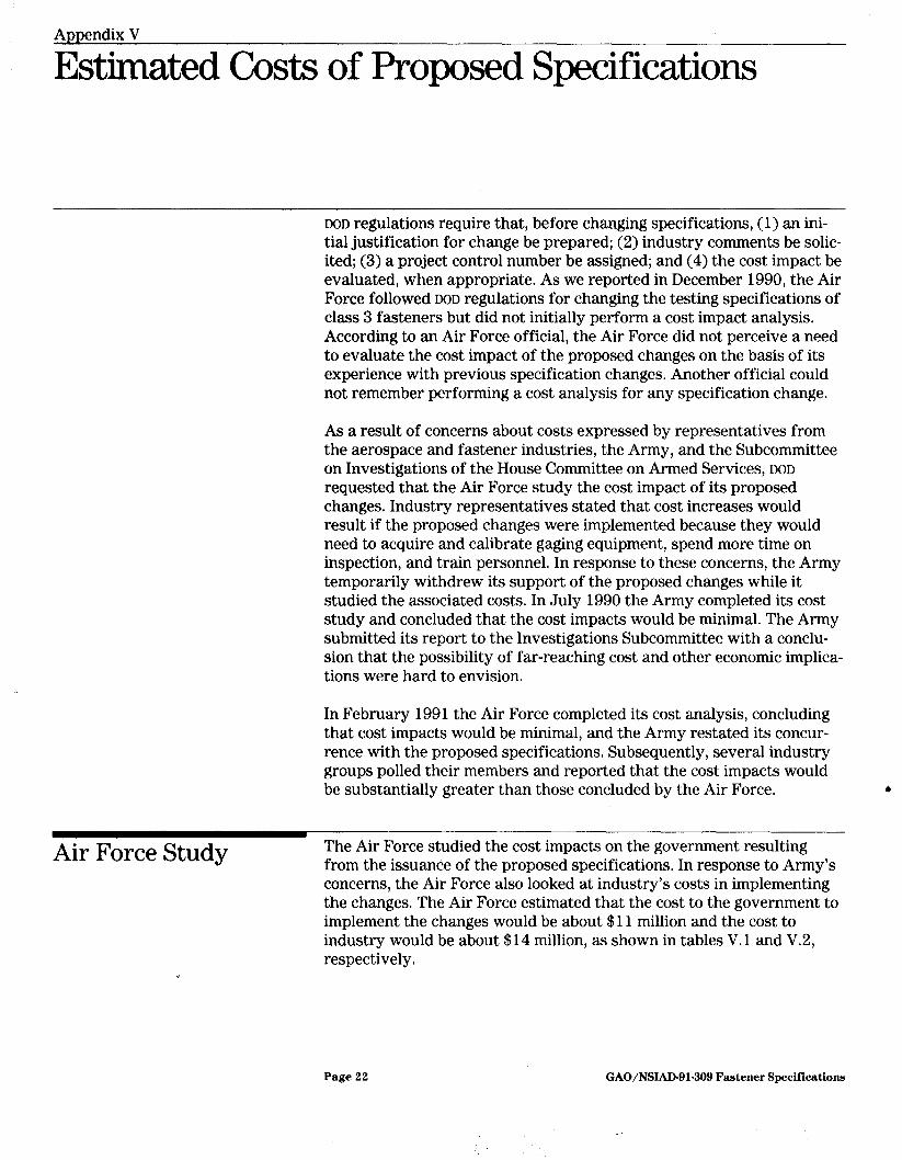
DOD regulations require that, before changing specifications, (1) an ini- tial justification for change be prepared; (2) industry comments be solic- ited; (3) a project control number be assigned; and (4) the cost impact be evaluated, when appropriate. As we reported in December 1990, the Air Force followed DOD regulations for changing the testing specifications of class 3 fasteners but did not initially perform a cost impact analysis. According to an Air Force official, the Air Force did not perceive a need to evaluate the cost impact of the proposed changes on the basis of its experience with previous specification changes. Another official could not remember performing a cost analysis for any specification change.
As a result of concerns about costs expressed by representatives from the aerospace and fastener industries, the Army, and the Subcommittee on Investigations of the House Committee on Armed Services, DOD requested that the Air Force study the cost impact of its proposed changes. Industry representatives stated that cost increases would result if the proposed changes were implemented because they would need to acquire and calibrate gaging equipment, spend more time on inspection, and train personnel. In response to these concerns, the Army temporarily withdrew its support of the proposed changes while it studied the associated costs. In July 1990 the Army completed its cost study and concluded that the cost impacts would be minimal. The Army submitted its report to the Investigations Subcommittee with a conclu- sion that the possibility of far-reaching cost and other economic implica- tions were hard to envision.
In February 1991 the Air Force completed its cost analysis, concluding that cost impacts would be minimal, and the Army restated its concur- rence with the proposed specifications. Subsequently, several industry groups polled their members and reported that the cost impacts would be substantially greater than those concluded by the Air Force. 1,
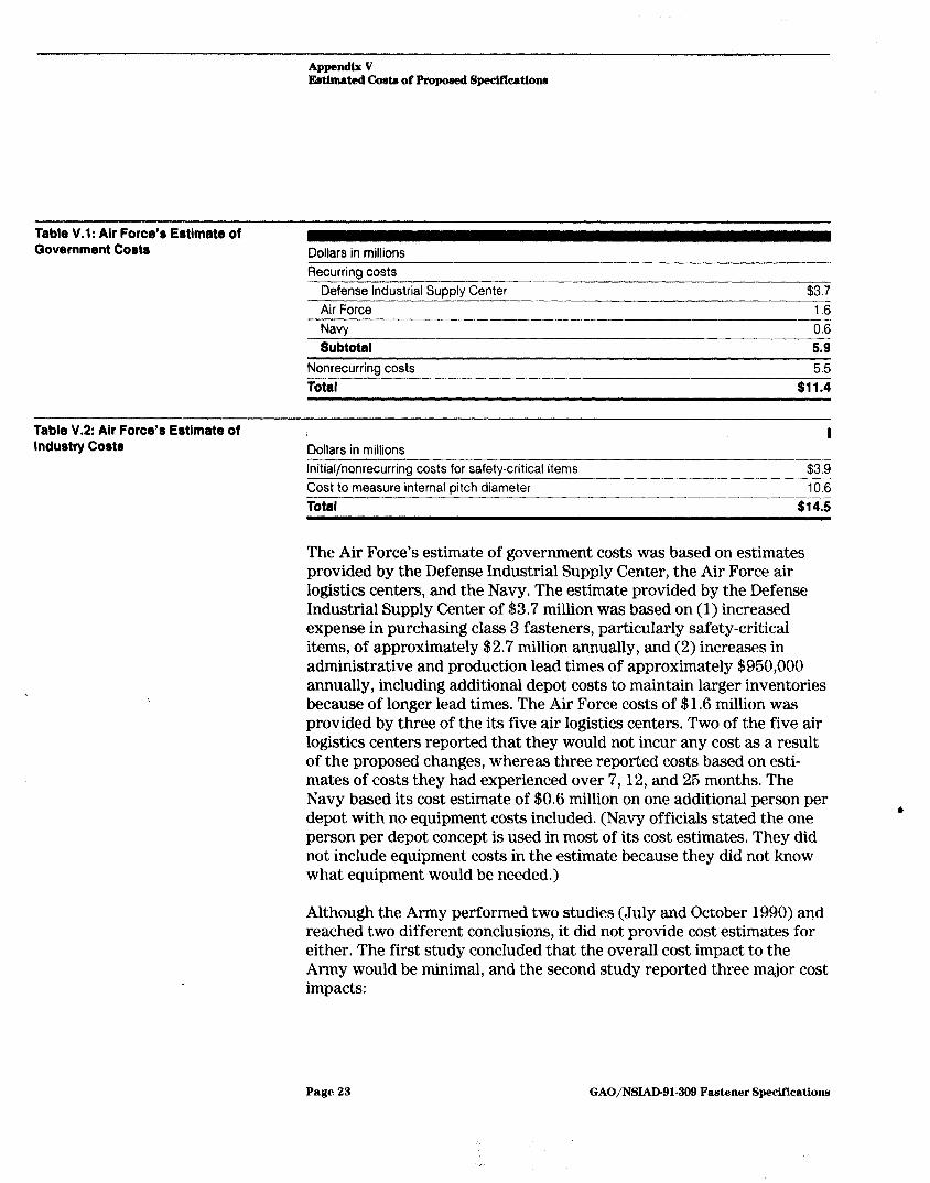
Air Force Study The Air Force studied the cost impacts on the government resulting from the issuance of the proposed specifications. In response to Army’s concerns, the Air Force also looked at industry’s costs in implementing the changes. The Air Force estimated that the cost to the government to implement the changes would be about $11 million and the cost to industry would be about $14 million, as shown in tables V.l and V.2, respectively.
Page 22 GAO/NSLAD-91-309 Fastener Specifications
Appendix V Fdmatmt lkata of Propof SpecifIcatlom
Table V.l: Air Force’s Estimate of Government Costs Dollars in millions
Recurring costs Defense Industrial Supply Center $3.7 Air Force 1.6
Navv 0.6
Subtotal 5.9 Nonrecurrina costs 5.5
Total $11.4
Table V.2: Air Force’s Estimate of Industry Costs Dollars in millions
I
Initial/nonrecurring costs for safety-critical items $3.9 Cost to measure internal pitch diameter Total
10.6
$14.5
The Air Force’s estimate of government costs was based on estimates provided by the Defense Industrial Supply Center, the Air Force air logistics centers, and the Navy. The estimate provided by the Defense Industrial Supply Center of $3.7 million was based on (1) increased expense in purchasing class 3 fasteners, particularly safety-critical items, of approximately $2.7 million annually, and (2) increases in administrative and production lead times of approximately $950,000 annually, including additional depot costs to maintain larger inventories because of longer lead times. The Air Force costs of $1.6 million was provided by three of the its five air logistics centers. Two of the five air logistics centers reported that they would not incur any cost as a result of the proposed changes, whereas three reported costs based on esti- mates of costs they had experienced over 7,12, and 25 months. The Navy based its cost estimate of $0.6 million on one additional person per depot with no equipment costs included. (Navy officials stated the one person per depot concept is used in most of its cost estimates. They did not include equipment costs in the estimate because they did not know what equipment would be needed.)
Although the Army performed two studies (July and October 1990) and reached two different conclusions, it did not provide cost estimates for either. The first study concluded that the overall cost impact to the Army would be minimal, and the second study reported three major cost impacts:
Page 23 GAO/NSIAD-91-309 Fastener Specifications
Appendix V Estimated Costa of Propoeed Speciflcatione
l an increased cost in production incurred by the manufacturer and passed on to the government for the inspection of all safety-critical fasteners;
. the obligation of money for longer periods of time and the longer lead time between obligation of money and actual receipt of safety-critical fasteners due to the delay in having all these items inspected; and
. an increased frequency of receiving complaints from contractors, causing an increase in government management of contracts.
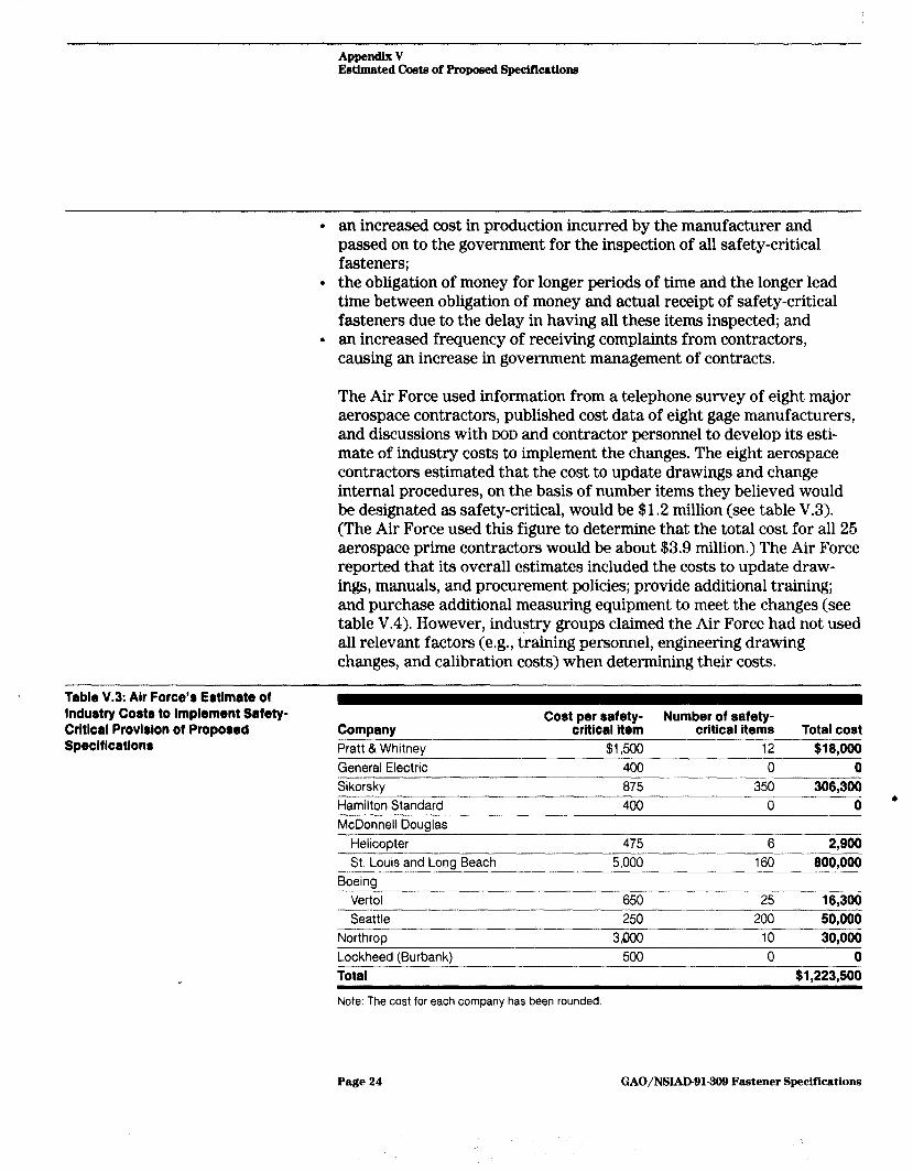
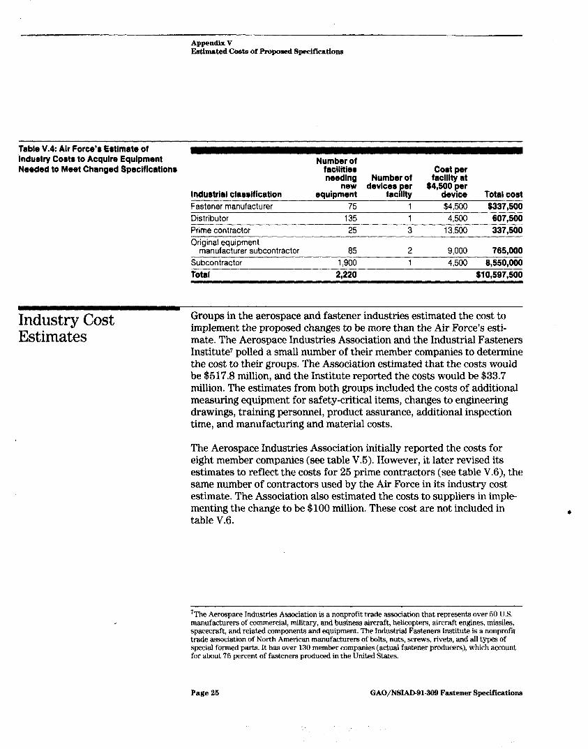
The Air Force used information from a telephone survey of eight major aerospace contractors, published cost data of eight gage manufacturers, and discussions with DOD and contractor personnel to develop its esti- mate of industry costs to implement the changes. The eight aerospace contractors estimated that the cost to update drawings and change internal procedures, on the basis of number items they believed would be designated as safety-critical, would be $1.2 million (see table V.3). (The Air Force used this figure to determine that the total cost for all 25 aerospace prime contractors would be about $3.9 million.) The Air Force reported that its overall estimates included the costs to update draw- ings, manuals, and procurement policies; provide additional training; and purchase additional measuring equipment to meet the changes (see table V.4). However, industry groups claimed the Air Force had not used all relevant factors (e.g., training personnel, engineering drawing changes, and calibration costs) when determining their costs.
Table V.3: Air Force’8 Estimate of lnduatry Coats to Implement Sakty- Critlcal Provleion of Proposed Specifications
Company Pratt & Whitney
Cost per safety- Number of safety- critical item critical items Total cost
$1,500 12 $18,000 General Electric 400 0 0 Sikorsky 875 350 306,300 Hamilton Standard 400 0 0 ’ McDonnell Douglas
Helicopter 475 6 2,900 St. Louis and Long Beach 5,000 160 800,000
Boeina Vertol 650 25 16,300 Seattle
Northroo 250 200 50,000
3000 IO 30.000 Lockheed (Burbank) Total
500 0 0 $1,223,500
Note: The cost for each company has been rounded.
Page 24 GAO/NSIAD91-399 Fastener Specifications
E&hated Costs of Proposed Specificatiom~
Table V.4: Air Force’8 Estimate of industry Costa to Acquire Equipment Number of Needed to Meet Changed Specification8 facilities Cobt per
needing Number of facility at new
Indu8trlal classification equipment devicgc ,;; $4,5itv~t;
P Total cost Fastener manufacturer 75 1 $4.500 $337,500 Distributor Prime contractor Original equipment
manufacturer subcontractor Subcontractor Total
135 1 4,500 607,500 25 3 13,500 337,500
85 2 9,000 765,000 1,900 1 4,500 6,550,OOO
2,220 $10,597,500
Industry Cost Estimates
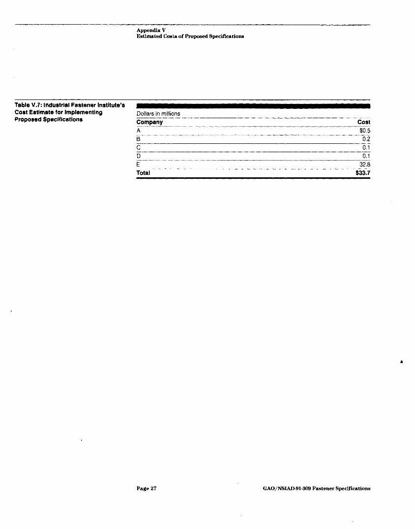
Groups in the aerospace and fastener industries estimated the cost to implement the proposed changes to be more than the Air Force’s esti- mate. The Aerospace Industries Association and the Industrial Fasteners Institute’ polled a small number of their member companies to determine the cost to their groups. The Association estimated that the costs would be $617.8 million, and the Institute reported the costs would be $33.7 million. The estimates from both groups included the costs of additional measuring equipment for safety-critical items, changes to engineering drawings, training personnel, product assurance, additional inspection time, and manufacturing and material costs.
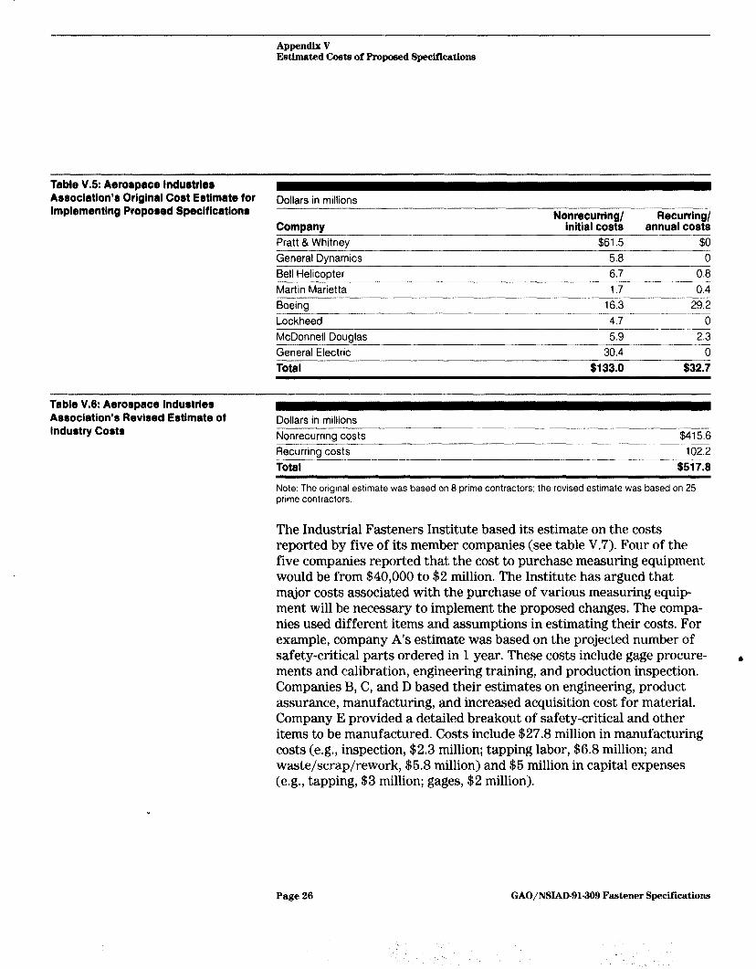
The Aerospace Industries Association initially reported the costs for eight member companies (see table V.5). However, it later revised its estimates to reflect the costs for 25 prime contractors (see table V.6), the same number of contractors used by the Air Force in its industry cost estimate. The Association also estimated the costs to suppliers in imple- menting the change to be $100 million. These cost are not included in table V.6.
‘The Aerospace Industries Association is a nonprofit trade association that represents over 60 U.S. manufacturers of commercial, military, and business aircraft, helicopters, aircraft engines, missiles, spacecraft, and related components and equipment. The Industrial Fasteners Institute is a nonprofit trade association of North American manufacturers of bolts, nuts, screws, rivets, and all types of special formed parts. It has over 130 member companies (actual fastener producers), which account for about 76 percent of fasteners produced in the United States.
Page 26 GAO/NSIAD-91-309 Fastener Specifications
Appendix V Estimated Cmte of Propomd Specifications
Table V.5: Aerospace industries Asaoclation’s Original Cost Estimate for implementing Proposed Specifications
Dollars in millions
Company Pratt &Whitney General Dynamics Bell Helicopter Martin Marietta Boeing Lockheed
Nonrecurring/ Recurring/ initial costs annual costs
$61.5 $0 5.8 0 6.7 0.8 1.7 0.4
16.3 292 4.7 0
McDonnell Douglas 5.9 2.3 General Electric 30.4 0 Total $133.0 $32.7
Table V.8: Aerospace industries Association’s Revised Estimate of industry Costs
Dollars in millions Nonrecurrina costs $415.6 Recurring costs Total
102.2 $517.6
Note: The original estimate was based on 8 prime contractors: the revised estimate was based on 25 prime contractors.
The Industrial Fasteners Institute based its estimate on the costs reported by five of its member companies (see table V.7). Four of the five companies reported that the cost to purchase measuring equipment would be from $40,000 to $2 million. The Institute has argued that major costs associated with the purchase of various measuring equip- ment will be necessary to implement the proposed changes. The compa- nies used different items and assumptions in estimating their costs. For example, company A’s estimate was based on the projected number of safety-critical parts ordered in 1 year. These costs include gage procure- & ments and calibration, engineering training, and production inspection. Companies B, C, and D based their estimates on engineering, product assurance, manufacturing, and increased acquisition cost for material. Company E provided a detailed breakout of safety-critical and other items to be manufactured. Costs include $27.8 million in manufacturing costs (e.g., inspection, $2.3 million; tapping labor, $6.8 million; and waste/scrap/rework, $5.8 million) and $5 million in capital expenses (e.g., tapping, $3 million; gages, $2 million).
Page 26 GAO/NSIAD-91-309 Fastener Specifications
Appendix V Estimated Costa of Proposed Specifications
Table V-7: Industrial Fastener Institute’s Cost Estimate for Implementing Dollars in millions Proposed Specifications Comoany - cost
A $0.5 B 0.2 ---.~ C 0.1 D 0.1 E ---.__I_ Total
32.8 $33.7
Page 27 GAO/NSIAD-91-309 Fastener Specifications
Ppe
i&!‘l99 1 Meeting Participants
.
.
.
.
.
.
.
.
.
.
.
.
.
.
.
.
.
.
.
.
.
.
.
.
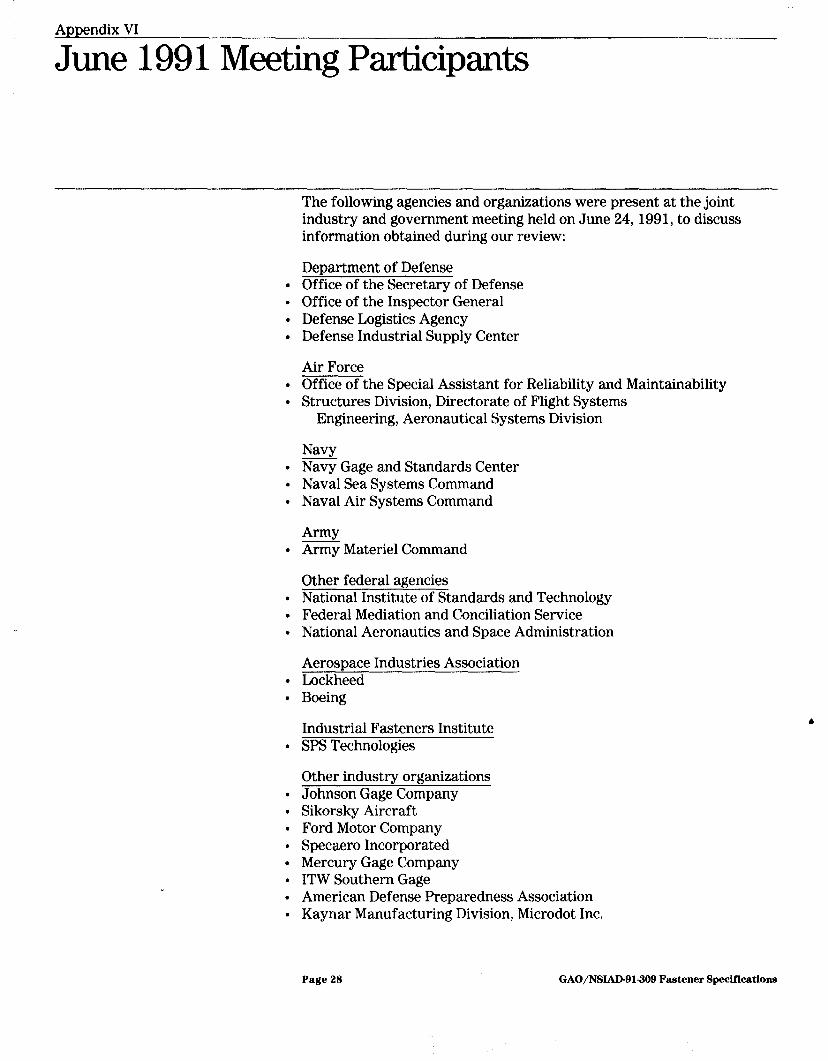
The following agencies and organizations were present at the joint industry and government meeting held on June 24, 1991, to discuss information obtained during our review:
Department of Defense Office of the Secretary of Defense Office of the Inspector General Defense Logistics Agency Defense Industrial Supply Center
Air Force Office of the Special Assistant for Reliability and Maintainability Structures Division, Directorate of Flight Systems
Engineering, Aeronautical Systems Division
Navy Navy Gage and Standards Center Naval Sea Systems Command Naval Air Systems Command
Army Army Materiel Command
Other federal agencies National Institute of Standards and Technology Federal Mediation and Conciliation Service National Aeronautics and Space Administration
Aerosnace Industries Association Lockheed Boeing
Industrial Fasteners Institute SPS Technologies
Other industry organizations Johnson Gage Company Sikorsky Aircraft Ford Motor Company Specaero Incorporated Mercury Gage Company ITW Southern Gage American Defense Preparedness Association Kaynar Manufacturing Division, Microdot Inc.
Page 29 GAO/NE&W-91309 Fastener Specif’lcations
Appendix VII
Major Contributors to This Report
National Security and Norman J. Rabkin, Associate Director
International Affairs John K. Harper, Assistant Director Curtis L. Evans, Evaluator-in-Charge
Division, Washington, Anthony Flake, Intern
DC.
Office of the General William T. Woods, Assistant General Counsel
Counsel
(mJ2ao9) Page 29 GAO/NSIAD-91-309 Fastener Specifications

,- .-..._ -..-.--.- . ^-- ----___.__ “_----.- _...-....-.-...- --“- ._... - __... l.-.l.---__---__
Related Documents