Teseq GmbH Landsberger Str. 255 12623 Berlin Germany T + 49 30 56 59 88 35 F + 49 30 56 59 88 34 [email protected] www.teseq.com 1 NSG 4070 0 . 1 4 7 8 5 2 3 6 9 Power meter ch. 1 stress level ch. 2 forward power ch. 3 reverse power 0.01 ... DCP 0100 1000 MHz DIRECTIONAL COUPLER Output Power amplifier input 50 Ω Termination Directional coupler NSG 4070 RF output Calibration jig BCI probe Ground plane NSG 4070 0 . 1 4 7 8 5 2 3 6 9 Power meter ch. 1 stress level ch. 2 forward power ch. 3 reverse power 0.01 ... DCP 0100 1000 MHz DIRECTIONAL COUPLER Output Power amplifier input 50 Ω Termination Directional coupler NSG 4070 RF output Calibration jig BCI probe Ground plane Attenuator 20 dB Note 2: The close loop method might require the use of the power limitation factor. The default value is 4 and required 4 x higher forward power as calibrated. The maximum needed forward power reached then approx. 25 Watts for a test level of 100 mA. Note 1: The measurement of the reverse power needs at least test levels of 25 mA. Note 3: The measurement of the reverse power needs at least test levels of 25 mA. Note 4: The close loop method might require the use of the power limitation factor. The default value is 4 and required 4 x higher forward power as calibrated. The maximum needed forward power reached then approx. 400 Watts for a test level of 400 mA. This required a 400 Watts power amplifier and 400 Watts directional coupler. NSG 4070 APPLICATION FOR BCI TO ISO 11452-4 Standard: ISO 11452-4:2005 Frequency range: 1 MHz to 400 MHz Level 1: 25 mA (15 dBm) Level 4: 100 mA (27 dBm) Level X: 400 mA (39 dBm) Modulation: e.g. CW, 1 kHz AM PC 80% (Peak conservation, ISO 11452-1) Test method: Substitution method or Closed-loop method Monitoring probe: only for information (substitu- tions method) or for power limitation (Closed-loop method) Test parameter Calibration set-up (for level 10 mA to 100 mA) Test levels for ISO 11452-4 ( 25 mA to 100 mA) Upper limit / Lower limit for this configuration (range below 1 MHz for information only and required additional 100 W power amplifier) Test levels for ISO 11452-4 ( 25 mA and 400 mA) Upper limit / Lower limit for this configuration (range below 1 MHz for information only and required additional 100 W power amplifier) Calibration set-up (for level 10 mA to 400 mA) Signal generation: NSG 4070-0 Modulator: AM , AM PC, PM included in NSG 4070-0 Power meter: 3x included in NSG 4070-0 Power amplifier: CBA 400M-100 (100 W, 1-400 MHz) Directional coupler: DCP 0100A (100 W) Current injection probe: CIP 9136A Monitoring probe: MD 4070 Calibration jig: PCJ 9201B Termination: 50 Ω 10 W Attenuation: 20 dB 10 W (for >100 mA) Software: incl. in NSG 4070 or C3I Equipment 83-253100 E02 ISO 11452-5 May 2009 0 10 20 30 40 50 60 70 80 90 100 110 10 kHz 100 kHz 150 kHz 1 MHz 400 MHz Frequency Current in mA 0 50 100 150 200 250 300 350 400 450 500 550 600 10 kHz 100 kHz 150 kHz 1 MHz 400 MHz Frequency Current in mA

Welcome message from author
This document is posted to help you gain knowledge. Please leave a comment to let me know what you think about it! Share it to your friends and learn new things together.
Transcript
Teseq GmbH Landsberger Str. 255 12623 Berlin Germany T + 49 30 56 59 88 35 F + 49 30 56 59 88 [email protected] www.teseq.com
1
RF out
Amp in
< +10 dBm
Amp outch.1 < +27 dBm
ch.2 < +20 dBm
ch.3 < +20 dBmPower meter
NSG 4070
PowerUSB
Tuning
StSizeStSize StSize
Local
Back StopRun
Hold
0 .
1
4
7 8
5
2 3
kHzdBm6
9 MHzdBµV
HzV
Enter
Step1
STO
FRQ LVL
RCL
Step2
Step3
MOD
2nd
Help
RFON/OFF Power meter
ch. 1 stress levelch. 2 forward powerch. 3 reverse power
Amp in Amp out
0.01 ...
DCP 0100
1000 MHz
DIRECTIONAL COUPLER
Output
Power amplifierinput
50 Ω Termination
Directional coupler
NSG 4070RF output
Calibration jig BCI probe Ground plane
RF out
Amp in
< +10 dBm
Amp outch.1 < +27 dBm
ch.2 < +20 dBm
ch.3 < +20 dBmPower meter
NSG 4070
PowerUSB
Tuning
StSizeStSize StSize
Local
Back StopRun
Hold
0 .
1
4
7 8
5
2 3
kHzdBm6
9 MHzdBµV
HzV
Enter
Step1
STO
FRQ LVL
RCL
Step2
Step3
MOD
2nd
Help
RFON/OFF Power meter
ch. 1 stress levelch. 2 forward powerch. 3 reverse power
Amp in Amp out
0.01 ...
DCP 0100
1000 MHz
DIRECTIONAL COUPLER
OutputPower amplifier input50 Ω Termination
Directional coupler
NSG 4070RF output
Calibration jig BCI probe Ground plane
Attenuator20 dB
Note 2: The close loop method might require the use of the power limitation factor. The default value is 4 and required 4 x higher forward power as calibrated. The maximum needed forward power reached then approx. 25 Watts for a test level of 100 mA.
Note 1: The measurement of the reverse power needs at least test levels of 25 mA.
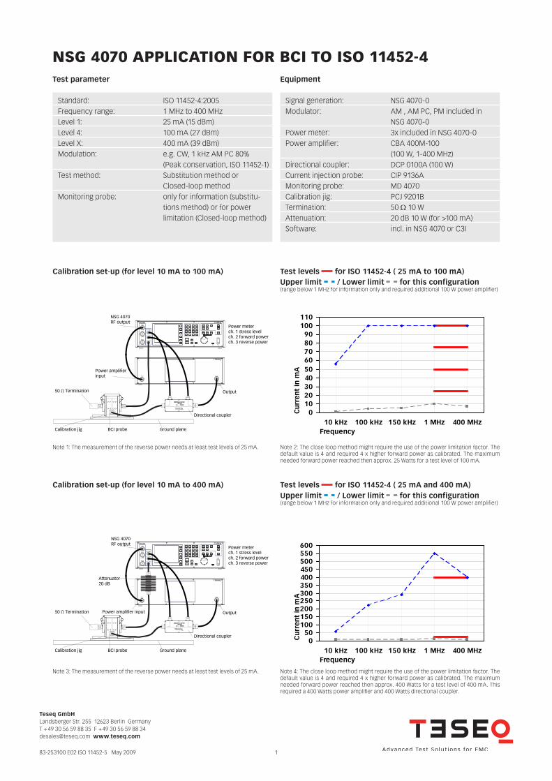
Note 3: The measurement of the reverse power needs at least test levels of 25 mA. Note 4: The close loop method might require the use of the power limitation factor. The default value is 4 and required 4 x higher forward power as calibrated. The maximum needed forward power reached then approx. 400 Watts for a test level of 400 mA. This required a 400 Watts power amplifier and 400 Watts directional coupler.
NSG 4070 ApplicAtioN for Bci to iSo 11452-4
Standard: ISO 11452-4:2005Frequency range: 1 MHz to 400 MHzLevel 1: 25 mA (15 dBm)Level 4: 100 mA (27 dBm)Level X: 400 mA (39 dBm)Modulation: e.g. CW, 1 kHz AM PC 80% (Peak conservation, ISO 11452-1)Test method: Substitution method or Closed-loop methodMonitoring probe: only for information (substitu- tions method) or for power limitation (Closed-loop method)
Test parameter
Calibration set-up (for level 10 mA to 100 mA) Test levels for ISO 11452-4 ( 25 mA to 100 mA)Upper limit / Lower limit for this configuration(range below 1 MHz for information only and required additional 100 W power amplifier)
Test levels for ISO 11452-4 ( 25 mA and 400 mA)Upper limit / Lower limit for this configuration (range below 1 MHz for information only and required additional 100 W power amplifier)
Calibration set-up (for level 10 mA to 400 mA)
Signal generation: NSG 4070-0Modulator: AM , AM PC, PM included in NSG 4070-0Power meter: 3x included in NSG 4070-0Power amplifier: CBA 400M-100 (100 W, 1-400 MHz)Directional coupler: DCP 0100A (100 W)Current injection probe: CIP 9136AMonitoring probe: MD 4070 Calibration jig: PCJ 9201BTermination: 50 Ω 10 WAttenuation: 20 dB 10 W (for >100 mA) Software: incl. in NSG 4070 or C3I
Equipment
83-253100 E02 ISO 11452-5 May 2009
0102030405060708090
100110
10 kHz 100 kHz 150 kHz 1 MHz 400 MHzFrequency
Cur
ren
t in
mA
050
100150200250300350400450500550600
10 kHz 100 kHz 150 kHz 1 MHz 400 MHzFrequency
Cur
ren
t in
mA

Teseq GmbH Landsberger Str. 255 12623 Berlin Germany T + 49 30 56 59 88 35 F + 49 30 56 59 88 [email protected] www.teseq.com
2
RF out
Amp in
< +10 dBm
Amp outch.1 < +27 dBm
ch.2 < +20 dBm
ch.3 < +20 dBmPower meter
NSG 4070
PowerUSB
Tuning
StSizeStSize StSize
Local
Back StopRun
Hold
0 .
1
4
7 8
5
2 3
kHzdBm6
9 MHzdBµV
HzV
Enter
Step1
STO
FRQ LVL
RCL
Step2
Step3
MOD
2nd
Help
RFON/OFF Power meter
ch. 1 response powerch. 2 forward powerch. 3 n. c.
Amp in Amp out
OutputPower amplifier input50 Ω Termination
Directional coupler
NSG 4070RF output
Calibration jig Monitoring probe Ground plane
0.01 ...
DCP 0100
1000 MHz
DIRECTIONAL COUPLER
RF out
Amp in
< +10 dBm
Amp outch.1 < +27 dBm
ch.2 < +20 dBm
ch.3 < +20 dBmPower meter
NSG 4070
PowerUSB
Tuning
StSizeStSize StSize
Local
Back StopRun
Hold
0 .
1
4
7 8
5
2 3
kHzdBm6
9 MHzdBµV
HzV
Enter
Step1
STO
FRQ LVL
RCL
Step2
Step3
MOD
2nd
Help
RFON/OFF Power meter
ch. 1 n.c.ch. 2 forward powerch. 3 reverse power
Amp in Amp out
OutputPower amplifier input
Directional coupler
NSG 4070RF output
Auxiliaryequipment
EUTAE
Equipmentunder test
Insulating BCI probeGround plane
0.01 ...
DCP 0100
1000 MHz
DIRECTIONAL COUPLER
RF out
Amp in
< +10 dBm
Amp outch.1 < +27 dBm
ch.2 < +20 dBm
ch.3 < +20 dBmPower meter
NSG 4070
PowerUSB
Tuning
StSizeStSize StSize
Local
Back StopRun
Hold
0 .
1
4
7 8
5
2 3
kHzdBm6
9 MHzdBµV
HzV
Enter
Step1
STO
FRQ LVL
RCL
Step2
Step3
MOD
2nd
Help
RFON/OFF Power meter
ch. 1 level monitoringch. 2 forward powerch. 3 reverse power
Amp in Amp out
OutputPower amplifier input
Directional coupler
NSG 4070RF output
Auxiliaryequipment
EUTAE
Equipmentunder test
Insulating BCI probe Monitoring probeGround plane
0.01 ...
DCP 0100
1000 MHz
DIRECTIONAL COUPLER
Note 4 gives more information about the hardware requirements of the close loop method with power limitation factor.
Test set-up close loop method or substitution method with monitoring probe (for Level 10 mA to 400 mA)
Test set-up substitution method without monitoring probe (for Level 10 mA to 400 mA)
Calibration set-up for monitoring probe
83-253100 E02 ISO 11452-5 May 2009
Related Documents