SECURE COMMUNICATION INTEROPERABILITY PROTOCOL (SCIP) The Secure Communication Interoperability Protocol (SCIP) is a communications standard developed by the National Security Agency (NSA) to enable interoperable secure communications among allies and partners around the globe. The SCIP-210 Signaling Plan is the specification that defines the application layer signaling used to negotiate a secure end-to-end session between two communication devices, independent of network transport. SCIP negotiates the operational mode (e.g., voice, data, etc.), the cryptographic algorithm suite (e.g., Suite A, Suite B, etc), and the traffic encryption key used for each secure session. It also provides capabilities for cryptographic synchronization and operational mode control between communicating end-point devices. SCIP is designed to operate over any network and is currently utilized in devices operating on a wide variety of networks including PSTN, ISDN, CDMA, GSM, IP, and satellite. Potential developers of SCIP devices may contact the NSA SCIP Program Office at [email protected] for further information. The SCIP-210 Signaling Plan is available without restrictions on its use for the development, manufacture, and sale of SCIP products. Compliance and interoperability testing will be necessary to ensure secure interoperability between the wide variety of current and future SCIP products.

Welcome message from author
This document is posted to help you gain knowledge. Please leave a comment to let me know what you think about it! Share it to your friends and learn new things together.
Transcript

SECURE COMMUNICATION INTEROPERABILITY PROTOCOL (SCIP)
The Secure Communication Interoperability Protocol (SCIP) is a communications standard developed by
the National Security Agency (NSA) to enable interoperable secure communications among allies and
partners around the globe.
The SCIP-210 Signaling Plan is the specification that defines the application layer signaling used to
negotiate a secure end-to-end session between two communication devices, independent of network
transport. SCIP negotiates the operational mode (e.g., voice, data, etc.), the cryptographic algorithm
suite (e.g., Suite A, Suite B, etc), and the traffic encryption key used for each secure session. It also
provides capabilities for cryptographic synchronization and operational mode control between
communicating end-point devices. SCIP is designed to operate over any network and is currently utilized
in devices operating on a wide variety of networks including PSTN, ISDN, CDMA, GSM, IP, and satellite.
Potential developers of SCIP devices may contact the NSA SCIP Program Office at
[email protected] for further information. The SCIP-210 Signaling Plan is available without
restrictions on its use for the development, manufacture, and sale of SCIP products. Compliance and
interoperability testing will be necessary to ensure secure interoperability between the wide variety of
current and future SCIP products.

SCIP-210 Revision 3.2
SCIP Signaling Plan
Revision 3.2
December 19, 2007
Prepared for:
National Security Agency 9800 Savage Road
Fort George G. Meade, MD 20755
Prepared By:
C4 Systems 77 “A” Street
Needham, MA 02494

SCIP-210 Revision 3.2
19 December 2007
i
TABLE OF CONTENTS
1.0 INTRODUCTION ....................................................................................................................1 1.1 Purpose..........................................................................................................................2 1.2 Scope.............................................................................................................................3 1.3 Definitions ....................................................................................................................4 1.4 Acronyms and Abbreviations .......................................................................................5 1.5 Applicable Documents..................................................................................................7
1.5.1 NSA Documents ............................................................................................7 1.5.2 Industry Standards .........................................................................................8 1.5.3 International and National Standards.............................................................8 1.5.4 Federal and DoD Standards ...........................................................................9 1.5.5 NATO Standards............................................................................................9 1.5.6 Other Relevant Technical Papers...................................................................9
1.6 Signaling Plan Overview ............................................................................................10 1.6.1 SCIP Application State Diagram .................................................................10 1.6.2 SCIP Protocol Layer Diagram .....................................................................12
1.7 Document Conventions...............................................................................................13 2.0 SCIP SIGNALING – Point-to-Point Operation......................................................................15
2.1 SCIP Message Transport ............................................................................................15 2.1.1 The MER-OC Message Transport Option and the Branch Point Mechanism...................................................................................................15 2.1.2 Message Transport Timelines ......................................................................16 2.1.3 Transport Framing .......................................................................................19
2.1.3.1 Start of Message............................................................................21 2.1.3.2 Frame Count..................................................................................21 2.1.3.3 Cyclic Redundancy Check............................................................21 2.1.3.4 Forward Error Control ..................................................................22 2.1.3.5 End of Message.............................................................................23
2.1.4 Escape ..........................................................................................................23 2.1.5 Transport Layer Control Messages..............................................................25
2.1.5.1 REPORT Message ........................................................................25 2.1.5.1.1 REPORT Message Format.............................................26 2.1.5.1.2 Conditions for REPORT Message Transmission ..........27 2.1.5.1.3 Processing for REPORT Message Reception................28
2.1.6 Message Transmission.................................................................................29 2.1.6.1 Transmit Request ..........................................................................29 2.1.6.2 Transmitter Actions on Receipt of a REPORT.............................33 2.1.6.3 Retransmit Timeout ......................................................................33
2.1.7 Message Reception ......................................................................................34 2.1.8 Octet Alignment...........................................................................................37
2.2 SCIP Call Setup Signaling..........................................................................................38 2.2.1 Introduction and Overview ..........................................................................38
2.2.1.1 Secure Call Setup Signaling Time Line........................................38 2.2.1.1.1 FIREFLY Example ........................................................38 2.2.1.1.2 PPK Example .................................................................40
SCIP-210 Revision 3.2 19 December 2007
ii
TABLE OF CONTENTS (Cont.)
2.2.1.2 First Message Time-Out ...............................................................42 2.2.1.3 Unrecognized Messages ...............................................................43 2.2.1.4 Message Limitations .....................................................................43
2.2.2 Capabilities Message ...................................................................................43 2.2.2.1 Capabilities Message Definition...................................................43 2.2.2.2 Capabilities Message Transmission..............................................56 2.2.2.3 Capabilities Message Reception ...................................................58
2.2.2.3.1 Capabilities Message Reception Unique Processing .....59 2.2.2.3.2 Common Capabilities Message Processing ...................60
2.2.2.4 Extended Keysets List Message Definition ..................................64 2.2.3 Parameters/Certificate Message...................................................................66
2.2.3.1 Parameters/Certificate Message Definition ..................................66 2.2.3.2 Parameters/Certificate Message Transmission .............................69 2.2.3.3 Parameters/Certificate Message Reception ..................................71
2.2.4 F(R) Message ...............................................................................................76 2.2.4.1 F(R) Message Definition ..............................................................76 2.2.4.2 F(R) Message Transmission .........................................................78 2.2.4.3 F(R) Message Reception...............................................................80
2.2.4.3.1 F(R) Message Received .................................................80 2.2.4.3.2 Parameters/Certificate Message Received.....................80
2.2.5 Cryptosync Exchange ..................................................................................81 2.2.5.1 Cryptosync Message Definition....................................................82 2.2.5.2 Cryptosync Message Transmission ..............................................83 2.2.5.3 Cryptosync Message Reception....................................................85
2.2.5.3.1 Cryptosync Message Received ......................................85 2.2.5.3.2 Parameters/Certificate Message Received.....................87
2.2.6 Operational Mode and Keyset Type Specific Instantiations .......................87 2.2.6.1 Key Agreement Specifics .............................................................87
2.2.6.1.1 Capabilities and Extended Keysets List Messages ........87 2.2.6.1.1.1 Type 1 FIREFLY Without CSE......................87 2.2.6.1.1.2 Type 1 FIREFLY With CSE...........................88 2.2.6.1.1.3 Type 1 U.S. Generic PPK Without CSE.........90 2.2.6.1.1.4 ECMQV/AES Without CSE – Phase 1...........90 2.2.6.1.1.5 ECMQV/AES With CSE – Phase 1................91 2.2.6.1.1.6 NATO ECMQV/AES Without CSE...............91 2.2.6.1.1.7 NATO ECMQV/AES With CSE ....................92 2.2.6.1.1.8 NATO PPK/AES Without CSE ......................94 2.2.6.1.1.9 Extended Keysets List Support.......................94
2.2.6.1.2 Parameters/Certificate Message.....................................95 2.2.6.1.2.1 Type 1 FIREFLY ............................................95 2.2.6.1.2.2 Type 1 U.S. Generic PPK ...............................95 2.2.6.1.2.3 ECMQV/AES – Phase 1 .................................95 2.2.6.1.2.4 NATO ECMQV/AES .....................................96 2.2.6.1.2.5 NATO PPK/AES ............................................96
SCIP-210 Revision 3.2
19 December 2007
iii
TABLE OF CONTENTS (Cont.)
2.2.6.1.3 F(R) Message .................................................................96 2.2.6.1.3.1 Type 1 FIREFLY ............................................97 2.2.6.1.3.2 Type 1 U.S. Generic PPK ...............................97 2.2.6.1.3.3 ECMQV/AES – Phase 1 .................................97 2.2.6.1.3.4 NATO ECMQV/AES .....................................97 2.2.6.1.3.5 NATO PPK/AES ............................................97
2.2.6.2 Secure Voice Specifics .................................................................98 2.2.6.2.1 Secure MELP and Secure G.729D Voice Options ......100 2.2.6.2.2 Secure AMBE Voice Specific Option .........................100
2.2.6.3 Secure Data Specifics .................................................................100 2.2.6.3.1 Secure Data Operational Mode Parameters .................101 2.2.6.3.2 Enhanced Secure Data Operational Mode Parameters 103
2.2.6.4 Secure Electronic Rekey Specifics .............................................104 2.2.6.5 Clear MELP Voice Specifics ......................................................105
2.3 SCIP Call Control Signaling.....................................................................................106 2.3.1 Call Control Timelines...............................................................................106 2.3.2 Notification Message Processing...............................................................109
2.3.2.1 Notification Message Definition.................................................110 2.3.2.2 Notification (Connection Terminate)..........................................114 2.3.2.3 Notification (Native Clear Voice/Connection Idle)....................116
2.3.2.3.1 Failed Call....................................................................119 2.3.2.3.2 Nonsecure Selected......................................................120 2.3.2.3.3 Secure Selected ............................................................120 2.3.2.3.4 Secure Restart ..............................................................120 2.3.2.3.5 Notification (Native Clear Voice/Connection Idle) Receive Processing ......................................................121
2.3.2.4 Notification (CKL Transfer) .......................................................121 2.3.2.5 Notification (Secure Dial)...........................................................124
2.3.2.5.1 Encryption of Secure Dial Characters .........................127 2.3.2.5.2 Data Transmission and Reception ...............................127
2.3.2.6 Notification (Attention) ..............................................................129 2.3.2.7 Notification (Secure Update) ......................................................131
2.3.3 Mode Change Processing...........................................................................134 2.3.3.1 Mode Change Request Message .................................................134 2.3.3.2 Mode Change Response Message...............................................137
2.3.4 Two-Way Resync Processing ....................................................................139 2.4 SCIP Signaling Timeouts..........................................................................................142 2.5 SCIP Signaling Constants .........................................................................................144
2.5.1 Source Definitions .....................................................................................144 2.5.2 MIDs ..........................................................................................................144 2.5.3 Miscellaneous SCIP Signaling Constants..................................................145
2.5.3.1 ESCAPE......................................................................................145 2.5.3.2 Start of Message (SOM) and End of Message (EOM) ...............145 2.5.3.3 START and FILLER...................................................................145
SCIP-210 Revision 3.2 19 December 2007
iv
TABLE OF CONTENTS (Cont.)
2.5.3.4 Headers .......................................................................................146 3.0 SCIP USER APPLICATION SIGNALING – Point-to-Point Operation .............................149
3.1 SCIP User Applications ............................................................................................149 3.2 Application Start-up/Restart Signaling.....................................................................149
3.2.1 Full Bandwidth Applications .....................................................................149 3.2.1.1 Application Timeout ...................................................................150
3.2.2 Reliable Transport Applications ................................................................152 3.3 Secure Voice Applications........................................................................................153
3.3.1 Secure MELP Voice ..................................................................................153 3.3.1.1 Secure 2400 bps MELP Voice – Blank and Burst......................153
3.3.1.1.1 Sync Management Frame ............................................154 3.3.1.1.2 Encryption and Transmission Ordering.......................156
3.3.1.2 Secure MELP Voice – Burst w/o Blank .....................................158 3.3.1.2.1 Sync Management Frame ............................................159 3.3.1.2.2 Encryption and Transmission Ordering.......................160
3.3.1.3 Clear MELP Voice – Blank and Burst........................................162 3.3.1.3.1 Sync Management Frame ............................................163 3.3.1.3.2 Transmission Ordering ................................................164
3.3.1.4 Voice Activity Factor Processing ...............................................165 3.3.1.4.1 Discontinuous Voice Transmission .............................165 3.3.1.4.2 Force Continuous Transmission ..................................165
3.3.2 Secure G.729D Voice ................................................................................166 3.3.2.1 Secure G.729D Voice Frame ......................................................168
3.3.2.1.1 Secure G.729D Voice Transmission Format ...............168 3.3.2.2 Sync Management Frame ...........................................................169 3.3.2.3 Encrypted Speech Frame Header................................................170 3.3.2.4 Encryption and Transmission Ordering......................................171 3.3.2.5 Discontinuous Voice Transmission ............................................173 3.3.2.6 Force Continuous Transmission .................................................173
3.4 Secure Data Applications..........................................................................................173 3.4.1 Secure Reliable Transport (RT) Asynchronous Data ................................173
3.4.1.1 Secure RT Asynchronous Data Transmission ............................174 3.4.1.1.1 Encryption and Transmission Ordering.......................175 3.4.1.1.2 Message Transmission.................................................177
3.4.1.2 Secure RT Asynchronous Data Message Reception...................177 3.4.2 Secure Best Effort Transport (BET) Asynchronous Data .........................177
3.4.2.1 Sync Management Frame ...........................................................180 3.4.2.2 Encryption and Transmission Ordering......................................180
4.0 SCIP ELECTRONIC REKEY SIGNALING .......................................................................183 4.1 Electronic Rekey Protocol Architecture and Communication Paths ........................184 4.2 SCIP Electronic Rekey Message Transport..............................................................186
4.2.1 Encryption and Transmission Ordering.....................................................187 4.2.2 SCIP Rekey Message Transmission ..........................................................188 4.2.3 SCIP Rekey Message Reception................................................................188
SCIP-210 Revision 3.2
19 December 2007
v
TABLE OF CONTENTS (Cont.)
4.3 Adaptation Layer ......................................................................................................189 4.4 Generic Rekey Application Layer ............................................................................190
5.0 SCIP SIGNALING – Multipoint Operation .........................................................................191 5.1 Multipoint Message Transport..................................................................................191
5.1.1 Multipoint Transport Framing ...................................................................191 5.1.1.1 Multipoint Message Transmission..............................................192 5.1.1.2 Multipoint Message Reception ...................................................192
5.1.2 Multipoint Cryptosync Message................................................................193 5.1.2.1 Multipoint Cryptosync Message Definition ...............................193 5.1.2.2 Multipoint Sync Parameters........................................................195
5.1.2.2.1 Sync Verification Pattern.............................................196 5.1.3 FILLER – Multipoint Operation................................................................196 5.1.4 START – Multipoint Operation.................................................................196 5.1.5 End of Transmission – Multipoint Operation ............................................196
5.2 Multipoint Session ....................................................................................................197 5.2.1 Multipoint Transmission............................................................................198
5.2.1.1 Multipoint Cryptosync Message Transmission ..........................199 5.2.1.2 Multipoint Secure Traffic Transmission.....................................201
5.2.1.2.1 Multipoint Secure MELP Voice Transmission............201 5.2.1.2.2 Multipoint Secure G.729D Voice Transmission..........202 5.2.1.2.3 Multipoint Secure Data Transmission .........................202
5.2.1.3 End of Multipoint Secure Traffic Transmission .........................203 5.2.2 Multipoint Reception .................................................................................204
5.2.2.1 Multipoint Cryptosync Message Reception................................204 5.2.2.2 Multipoint Secure Traffic Reception ..........................................206
5.2.2.2.1 Multipoint Secure MELP Voice Reception .................207 5.2.2.2.2 Multipoint Secure G.729D Voice Reception...............207 5.2.2.2.3 Multipoint Secure Data Reception...............................207
5.2.2.3 Late Entry (Including Re-Entry).................................................207 5.2.2.4 End of Multipoint Secure Traffic Reception ..............................209
A.0 SCIP MESSAGE TRANSPORT PROTOCOL EXAMPLES ............................................ A-1 A.1 Normal Capabilities Message Transfer................................................................... A-2 A.2 Parameters/Certificate Message Transfer with Corrupted and Missing Frames .... A-4 A.3 F(R) Message Transfer with Corrupted SOM and EOM Sequences ...................... A-7 A.4 CAPABILITIES Message Transfer with Corrupted REPORT Responses........... A-10 A.5 Normal Transition from Signaling to Full Bandwidth Application...................... A-13 A.6 Transition from Signaling to Full Bandwidth Application with Final REPORT Lost ....................................................................................................................... A-16 A.7 Transition from Signaling to Full Bandwidth Application with START Lost ..... A-20 A.8 Two Way Resync from Full Bandwidth Application, Terminal A is Leader ....... A-24 A.9 Two Way Resync from Full Bandwidth Application with Corrupted ESC Sequence, Terminal A is Leader........................................................................... A-27 A.10 Normal Termination from Full Bandwidth Application, Terminal A is Leader. A-30 A.11 Terminal A Sends Notify(Attention) from Full Bandwidth Application............ A-32
SCIP-210 Revision 3.2 19 December 2007
vi
TABLE OF CONTENTS (Cont.) B.0 DISCONTINUOUS VOICE (DTX) ....................................................................................B-1
B.1 Voice Activity Detection (VAD) .............................................................................B-1 B.2 Default Voice Activity Detection (VAD) Algorithm...............................................B-2 B.3 Grace Period.............................................................................................................B-3 B.4 Blank Period.............................................................................................................B-4 B.5 Comfort Noise ..........................................................................................................B-5 B.6 Re-Start ....................................................................................................................B-5
C.0 PERFORMANCE ................................................................................................................C-1 C.1 DTX Voice ...............................................................................................................C-1
C.1.1 MELP Blank and Burst ..............................................................................C-1

SCIP-210 Revision 3.2
19 December 2007
vii
LIST OF FIGURES
Figure 1.6-1 SCIP Application State Diagram - Point-to-Point .................................................. 11 Figure 1.6-2 SCIP Protocol Layer Diagram - Point-to-Point ...................................................... 12 Figure 1.7-1 Process Diagram Symbols....................................................................................... 13 Figure 2.1-1(a) Transport Layer Signaling Time Line (Framed) ................................................ 17 Figure 2.1-1(b) Transport Layer Signaling Time Line (Full bandwidth-to-Framed) .................. 18 Figure 2.1-1(c) Transport Layer Signaling Time Line (Full bandwidth-to-Full bandwidth) ...... 18 Figure 2.1-2 Transmission Frame Group..................................................................................... 19 Figure 2.1-3 ESCAPE Processing ............................................................................................... 24 Figure 2.1-4(a) Message Transmission........................................................................................ 31 Figure 2.1-4(b) Message Transmission (Cont.) ........................................................................... 32 Figure 2.1-5(a) Message Reception ............................................................................................. 35 Figure 2.1-5(b) Message Reception (Cont.) ................................................................................ 36 Figure 2.2-1(a) FIREFLY Secure Call Setup Signaling Time Line ............................................ 39 Figure 2.2-1(b) PPK Secure Call Setup Signaling Time Line..................................................... 41 Figure 2.2-2 Capabilities Message Transmission ........................................................................ 57 Figure 2.2-3 Capabilities Message Reception Unique Processing .............................................. 60 Figure 2.2-4 Common Capabilities Message Processing ............................................................ 62 Figure 2.2-5 Parameters/Certificate Message Transmission ....................................................... 70 Figure 2.2-6(a) Parameters/Certificate Message Reception ........................................................ 72 Figure 2.2-6(b) Parameters/Certificate Message Reception (Cont.) ........................................... 73 Figure 2.2-6(c) Parameters/Certificate Message Reception (Cont.)............................................ 74 Figure 2.2-7 F(R) Message Transmission.................................................................................... 79 Figure 2.2-8 F(R) Message Reception......................................................................................... 81 Figure 2.2-9 Cryptosync Message Transmission......................................................................... 84 Figure 2.2-10 Cryptosync Message Reception ............................................................................ 86 Figure 2.3-1(a) Notification Message Signaling Time Line (Full Bandwidth to Framed)........ 107 Figure 2.3-1(b) Notification Message Signaling Time Line (Framed to Framed) .................... 107 Figure 2.3-1(c) Notification Message Signaling Time Line (Full Bandwidth to Full
Bandwidth)........................................................................................................ 107 Figure 2.3-1(d) Mode Change Signaling Time Line ................................................................. 108 Figure 2.3-1(e) Two-Way Resync Signaling Time Line ........................................................... 108 Figure 2.3-2 Notification Message Processing (Connection Terminate) .................................. 115 Figure 2.3-3(a) Notification Message Processing (Native Clear Voice/Connection Idle) ........ 117 Figure 2.3-3(b) Notification Message Processing (Native Clear Voice/Connection Idle)
(Cont.) ............................................................................................................... 118 Figure 2.3-4 Notification Message Receive Processing (CKL Transfer).................................. 124 Figure 2.3-5 Notification Message Processing (Secure Dial) ................................................... 126 Figure 2.3-6 Notification Message Processing (Attention) ....................................................... 130 Figure 2.3-7 Notification Message Processing (Secure Update)............................................... 133 Figure 2.3-8 Mode Change Processing...................................................................................... 135 Figure 2.3-9 Two-Way Resync Processing ............................................................................... 140 Figure 3.2-1 Application Timeout Processing........................................................................... 151 Figure 3.3-1 Secure MELP Voice Transmission Format – Blank and Burst ............................ 154 Figure 3.3-2 Sync Management Frame Format – Blank and Burst ........................................... 154
SCIP-210 Revision 3.2 19 December 2007
viii
LIST OF FIGURES (Cont.) Figure 3.3-3 Secure MELP Voice Transmission Format – Burst w/o Blank ............................ 159 Figure 3.3-4 Sync Management Frame Format – Burst w/o Blank........................................... 159 Figure 3.3-5 Clear MELP Voice Transmission Format............................................................. 163 Figure 3.3-6 Clear MELP Voice Sync Management Frame Format ......................................... 163 Figure 3.3-7 Secure G.729D Voice Transmission..................................................................... 166 Figure 3.3-8 Secure G.729D Voice Superframe Details ........................................................... 167 Figure 3.3-9 Secure G.729D Voice Escape and Return Example (No Cryptosync) ................. 167 Figure 3.3-10 Secure G.729D Voice Sync Management Frame Format................................... 169 Figure 3.3-11 Secure G.729D Voice Encrypted Speech Frame Header.................................... 170 Figure 3.4-1 Secure RT Asynchronous Data Message Preparation........................................... 174 Figure 3.4-2 V.14 Asynchronous Data Input Ordering ............................................................. 175 Figure 3.4-3 Secure BET Asynchronous Data Transmission Format ....................................... 178 Figure 3.4-4 Secure BET Asynchronous Data Superframe Structure ....................................... 179 Figure 3.4-5 Sync Management Frame Format ......................................................................... 180 Figure 3.4-6 V.14 Asynchronous Data Input Ordering ............................................................. 180 Figure 4.1-1 Rekey Protocol Conversion Using the GRFE....................................................... 184 Figure 4.1-2 Electronic Rekey System Infrastructure ............................................................... 185 Figure 4.2-1 SCIP Rekey Message Preparation......................................................................... 186 Figure 5.1-1 Multipoint Transport Signaling Timeline ............................................................. 191 Figure 5.1-2 Multiple Multipoint Cryptosync Message Transmissions .................................... 192 Figure 5.2-1 SCIP Multipoint State Diagram ............................................................................ 197 Figure 5.2-2 Multipoint Secure Voice Transmit Signaling Time Line...................................... 198 Figure 5.2-3 Multipoint Cryptosync Message Transmission..................................................... 200 Figure 5.2-4 Multipoint MELP Voice Transmission Format – Blank and Burst ...................... 202 Figure 5.2-5 End of Multipoint Secure Traffic Transmission ................................................... 203 Figure 5.2-6 Multipoint Cryptosync Message Reception.......................................................... 205 Figure 5.2-7 Multipoint Secure Voice Traffic Reception.......................................................... 206 Figure 5.2-8 Multipoint Late Entry Cryptographic Synchronization ........................................ 208 Figure 5.2-9 End of Multipoint Secure Traffic Reception......................................................... 209 Figure B-1 DTX Voice .............................................................................................................. B-1
SCIP-210 Revision 3.2
19 December 2007
ix
LIST OF TABLES Table 2.1-1 Frame Group Format ................................................................................................ 20 Table 2.1-2 REPORT Message Data Format............................................................................... 26 Table 2.2-1(a) Capabilities Message Format............................................................................... 44 Table 2.2-1(b) Capabilities Message Format (Cont.) .................................................................. 45 Table 2.2-1(c) Capabilities Message Format – Version 1 or Higher (Cont.) .............................. 45 Table 2.2-2 SCIP Standard Operational Modes........................................................................... 47 Table 2.2-3(a) Keysets List Entry - General Format ................................................................... 48 Table 2.2-3(b) SCIP Standard Keyset Types............................................................................... 49 Table 2.2-3(c) Terminal Priority COI Values.............................................................................. 50 Table 2.2-3(d) Terminal Priority Values ..................................................................................... 50 Table 2.2-3(e) Example of Capabilities Message Contents – Enhanced FF Capable ................. 52 Table 2.2-3(f) Extended Keysets List Message Format .............................................................. 65 Table 2.2-4 Parameters/Certificate Message Format................................................................... 67 Table 2.2-5 F(R) Message - General Format ............................................................................... 77 Table 2.2-6 Cryptosync Message - General Format .................................................................... 82 Table 2.2-7(a) Keyset Parameters Entry – Type 1 Basic and Enhanced FF w/o CSE Format.... 88 Table 2.2-7(b) Keyset Parameters Entry – Type 1 Basic and Enhanced FF w/CSE Format....... 89 Table 2.2-7(c) Keyset Parameters Entry – Type 1 U.S. Generic PPK w/o CSE Format............. 90 Table 2.2-7(d) Keyset Parameters Entry – ECMQV/AES w/o CSE – Phase 1 Format .............. 90 Table 2.2-7(e) Keyset Parameters Entry – ECMQV/AES w/CSE – Phase 1 Format.................. 91 Table 2.2-7(f) Keyset Parameters Entry – NATO ECMQV/AES w/o CSE Format ................... 92 Table 2.2-7(g) Keyset Parameters Entry – NATO ECMQV/AES w/CSE Format...................... 93 Table 2.2-7(h) Keyset Parameters Entry – NATO PPK/AES w/o CSE Format.......................... 94 Table 2.2-7(i) Keyset Parameters Entry – Extended Keysets List Support Format .................... 94 Table 2.2-8 Certificate Field Format ........................................................................................... 95 Table 2.2-9 F(R) Field Format..................................................................................................... 96 Table 2.2-10 Operational Mode Parameters – Secure Voice....................................................... 98 Table 2.2-11 Interoperable Security Levels................................................................................. 99 Table 2.2-12 Secure Voice Options........................................................................................... 100 Table 2.2-13 Secure Data/Enhanced Secure Data Options........................................................ 101 Table 2.2-14 Operational Mode Parameters – Secure Data....................................................... 102 Table 2.2-15(a) Operational Mode Parameters – Enhanced Secure Data ................................. 103 Table 2.2-15(b) Enhanced Secure Data Option Entry ............................................................... 103 Table 2.2-16 Operational Mode Parameters – Secure Electronic Rekey .................................. 104 Table 2.2-17 Electronic Rekey Options..................................................................................... 105 Table 2.3-1 Notification Message Format ................................................................................. 110 Table 2.3-2 SCIP Standard Action Field Values ....................................................................... 111 Table 2.3-3 Information Field Entry Format ............................................................................. 112 Table 2.3-4 SCIP Standard Information Code Definitions........................................................ 113 Table 2.3-5 CKL Transfer - Information Text........................................................................... 122 Table 2.3-6 Secure Dial Characters ........................................................................................... 125 Table 2.3-7 Secure Dial - Information Text .............................................................................. 128 Table 2.3-8 Secure Update - Information Text.......................................................................... 131 Table 2.3-9 Mode Change Request Message Format ................................................................ 136
SCIP-210 Revision 3.2 19 December 2007
x
LIST OF TABLES (Cont.) Table 2.3-10 Mode Change Response Message Format............................................................ 138 Table 2.4-1 SCIP Signaling Timeouts ....................................................................................... 142 Table 2.5-1 Source Definitions .................................................................................................. 144 Table 2.5-2 MIDs....................................................................................................................... 144 Table 2.5-3 Miscellaneous SCIP Signaling Constants .............................................................. 147 Table 3.3-1 Sync Management Frame Contents – Blank and Burst.......................................... 155 Table 3.3-2 Secure MELP Transmission Bit Ordering – Blank and Burst................................ 157 Table 3.3-3 Sync Management Frame Contents – Burst w/o Blank ......................................... 160 Table 3.3-4 Secure MELP Transmission Bit Ordering – Burst w/o Blank ............................... 161 Table 3.3-5 Clear MELP Voice Sync Management Frame Contents........................................ 164 Table 3.3-6 Clear MELP Voice Transmission Bit Ordering – Blank and Burst ....................... 164 Table 3.3-7 Secure G.729D Voice Frame Parameters............................................................... 168 Table 3.3-8 G.729D Vocoder Frame Bit Transmission Order................................................... 169 Table 3.3-9 Secure G.729D Voice Sync Management Frame Contents.................................... 170 Table 3.3-10 Secure G.729D Voice Encrypted Speech Frame Header Contents...................... 170 Table 3.3-11(a) Secure G.729D Voice Transmission Bit Ordering (Octets 1 - 8) .................... 171 Table 3.3-11(b) Secure G.729D Voice Transmission Bit Ordering (Octets 9 - 288) ................ 172 Table 3.4-1 Secure RT Asynchronous Data Message Format................................................... 176 Table 3.4-2 Validity Count Field Values................................................................................... 179 Table 3.4-3 Sync Management Frame Contents........................................................................ 180 Table 3.4-4 Secure BET Asynchronous Data Transmission Bit Ordering ................................ 181 Table 4.2-1 SCIP Rekey Message Format................................................................................. 187 Table 4.4-1 Generic Rekey Protocol Data Units (GRPDUs)..................................................... 190 Table 5.1-1 Multipoint Cryptosync Message – General Format ............................................... 193 Table 5.1-2 Sync Parameters ..................................................................................................... 195 Table B.1-1 DTX VAF Values .................................................................................................. B-2 Table B.3-1 MELP Comfort Noise Parameter Values............................................................... B-4 Table B.4-1 Blank Period Values .............................................................................................. B-4
SCIP-210 Revision 3.2
19 December 2007
xi
***Signaling Plan Notice***
Revision 3.2 of the SCIP Signaling Plan, designated as SCIP-210, is an update of Revision 3.1. It incorporates changes from ECPs 26 and 27. The more significant changes are listed below.
• Applicable documents were updated and acronyms were added.
• A Message Limitations section was added to ensure interoperability with SCIP devices.
• Signaling changes for Extended Keysets Lists were added.
An Extended Keysets List Message and an Extended Keysets List Support Keyset were added to extend the keyset list in the Capabilities Message.
The Common Capabilities Message Processing and Secure Call Setup
Signaling Time Lines were modified to show optional Extended Keysets List Message exchanges.
• Signaling changes for Enhanced Secure Data were added.
An Enhanced Secure Data Operational mode was added along with an
Enhanced Secure Data Operational Mode Parameters format.
Data options may be listed in the Operational Mode Parameters associated with Secure Data, Enhanced Secure Data, or both Operational Mode(s).
• Clarified that SCIP signaling can be used to negotiate specific data application uses (e.g.,
fax, chat) of data Options (e.g., Secure RT Data) by assigning them a different Option ID.
• Guaranteed Throughput (GT) Data was renamed to Best Effort Transport (BET) Data.
References to 2400 bps were removed; this data mode scales to any data rate.
• References to the order in which bits are encrypted were removed since the requirements are specified in the cryptographic specifications.
• Bit ordering at the application layer was separated from bit ordering at the lower layers.
SCIP terminal transmission bit ordering over various network interfaces will
be provided in SCIP-214 and SCIP-215. All changes are indicated by change bars. If changes were made to a figure or a table, a change bar appears at the end of the title.

SCIP-210 Revision 3.2 19 December 2007
xii
THIS PAGE INTENTIONALLY LEFT BLANK.
SCIP-210 Revision 3.2
19 December 2007
1
1
1.0 INTRODUCTION 2
3
This document specifies the signaling requirements for the Secure Communication 4
Interoperability Protocol (SCIP) operational modes. The requirements represent the efforts of a 5
working group established for the development, analysis, selection, definition and refinement of 6
signaling for the operational modes of a new class of secure voice and data terminals intended 7
for use on the emerging digital narrowband channels. These channels include digital cellular 8
systems such as GSM and CDMA, digital mobile satellite systems, and a variety of other 9
narrowband digital systems that are also within the scope of interest for the working group. The 10
SCIP signaling is designed to be sufficiently flexible so that subsequent updates and revisions 11
may include various future networks of interest. 12
13
The main body of the SCIP Signaling Plan contains requirements common to all SCIP 14
implementations. It specifies a secure overlay capable of interoperation with SCIP compatible 15
equipment on various similar or disparate networks. Since the various networks will often have 16
different lower-layer communications protocols, the SCIP secure overlay specification specifies 17
the higher-layer end-to-end protocols only. The implementation-specific details for a terminal 18
connected to a particular network are defined in an appendix specific to that network. The 19
appendices specify modes, service options, and other network-specific issues that do not affect 20
terminals on another network. A full terminal design requires the secure overlay specification 21
and the appendix with the requirements for use of the lower-layer communications interface. 22
The secure overlay description and the appendices may be published as a single document or 23
separately as desired. 24
25
The goal of separating the secure overlay from the network-specific appendices is to ensure that 26
there is a stable specification for interoperability and to avoid confusion caused by the differing 27
requirements for the various networks. A specific product development will involve generation 28
of a network-specific appendix which is independent of the application overlay requirements. 29
Each terminal development program (e.g., CDMA cellular, etc.) can proceed independently by 30
generating and/or modifying the implementation-specific appendix for that network. By 31
avoiding modifications to the secure overlay description, configuration management will be 32
simplified. Also, developers of a terminal for one network need not be concerned with the 33
lower-layer requirements for another network. 34
35
36
SCIP-210 Revision 3.2 19 December 2007
2
37
1.1 Purpose 38
39
The purpose of this document is to define the signaling for point-to-point and multipoint secure 40
communication among terminals operating over narrowband digital networks. The Signaling 41
Plan defines: 42
43
(1) The exchange of keys, certificates or other information between point-to-point terminals 44
preparatory to the exchange of secure voice or data traffic, 45
46
(2) The transmission of secure voice traffic among the user terminals for point-to-point and 47
multipoint operation using the DoD standard MELP or NATO standard MELPe vocoder at 2400 48
bps, and the ITU-T Recommendation G.729 Annex D CS-ACELP vocoder at 6400 bps, 49
50
(3) The transmission of secure data traffic between the user terminals for point-to-point 51
secure data communication, 52
53
(4) The security control signaling necessary to establish, maintain, and terminate the secure 54
mode of operation, 55
56
(5) The signaling to support point-to-point electronic or over-the-air rekey of the keys or 57
keying material used by the terminals, 58
59
(6) The signaling point of departure to allow vendors to add proprietary signaling and modes 60
of operation to the interoperable standard modes defined by the remainder of the signaling plan. 61
62
The purpose of this Signaling Plan is to support communication between SCIP terminals 63
independent of the transport network being used (e.g., digital wireless networks, IP networks, 64
and PSTN/ISDN networks). The signaling is intended to operate using commercially available 65
standards based data services, and standard Interworking Functions (IWFs) with no need for 66
additional specialized interworking functions or operations. 67
68
Within the class of commercially operated digital wireless networks, the purpose of this 69
Signaling Plan is to define the signaling required for secure voice operation over the CDMA and 70
GSM digital cellular systems, mobile satellite systems, and other narrowband digital systems. 71
72
SCIP-210 Revision 3.2
19 December 2007
3
73
1.2 Scope 74
75
This Signaling Plan is intended to specify the end-to-end signaling used by the secure voice and 76
data elements. Nothing will be contained in the Signaling Plan about the additional signaling 77
within the communication links that might be used to convey the signaling between the terminal 78
elements. 79
80
It is within the scope of this Signaling Plan to provide flexibility for the extension to subsequent 81
versions so that if changes are required to incorporate additional networks and objectives, the 82
changes can be incorporated. 83
84
It is not within the scope of the Signaling Plan to dictate or otherwise specify any particular 85
method of implementation. Where implementation methods may be implied by the signaling, 86
this is only for illustrative purposes. The potential for new features after the first equipment 87
models, however, suggests that implementers may want to perform the implementation with 88
some flexibility and expansion potential for subsequent models of equipment designed to operate 89
over additional networks. 90
91
The Signaling Plan is intended to define the SCIP overlay signaling for the clear digital voice 92
and secure voice/data applications using a standard data bearer service. The SCIP clear digital 93
voice mode signaling is based on the possibility that a voice-followed-by-data communications 94
service for the clear to secure mode transition may not exist. Note that the SCIP clear digital 95
voice mode utilizes SCIP specific signaling and is compatible with SCIP devices only. 96
97
Signaling aspects that are specifically outside the scope of this signaling plan are: 98
99
(1) Signaling for the creation of the network connection between terminals as required to 100
establish a path for the “native” (non-SCIP) clear or non-secure mode of operation. 101
102
(2) Signaling for establishing the bearer service or service option preparatory to the initiation 103
of the secure mode of operation. 104
105
SCIP-210 Revision 3.2 19 December 2007
4
106
1.3 Definitions 107
108
The following terms are used throughout this document: 109
110
Initiator - The terminal that initiates the secure call setup. 111
112
Responder - The terminal that responds to the signaling sequence started by the Initiator. 113
114
Leader - The terminal that begins a signaling sequence as a result of some user/machine 115
determined condition, e.g., out of sync detection, voice/data transition, activating the non-secure 116
control, or an error (failed call) condition. 117
118
Follower – The terminal that responds to the signaling sequence started by the Leader. 119
120
Local – The terminal where operation is currently being described. 121
122
Remote – The far-end terminal. 123
124
Clear – Not encrypted (does not refer to a user action). 125
126
Protected – A level of security used for Sensitive, but Unclassified information. Note that 127
“protected” with a lower case “p” refers to the standard English definition. 128
129
Credentials – Certificate and F(R). 130
131
MER-OC – If this capability is implemented, it must be as specified herein. 132
133
Type 1 – NSA approved encryption for protection of Classified information. 134
135
Non-Type 1 – NSA or NIST approved encryption for protection of Sensitive, but Unclassified 136
information. 137
138
ECMQV/AES – Non-Type 1 cryptographic suite that is specified in SCIP-231. 139
140
NATO ECMQV/AES – NATO interim cryptographic suite, specified in SCIP-232, for protection 141
of Classified information. 142
143
SCIP-23x – The Cryptography Specifications listed in Section 1.5.1 (e.g., SCIP-230, SCIP-231, 144
or SCIP-232). 145
146
SCIP-210 Revision 3.2
19 December 2007
5
147
1.4 Acronyms and Abbreviations 148
149
The following acronyms and abbreviations are used within this document. 150
151
ACL - Access Control List 152
AES - Advanced Encryption Standard 153
AMBE - Advanced Multi-Band Excitation 154
APDU - Application Protocol Data Unit 155
ASN.1 - Abstract Syntax Notation One 156
BCH - Bose-Chaudhuri, Hocquenghem (Error Correcting Code) 157
BER - Bit Error Rate 158
BET - Best Effort Transport 159
bps - bits per second 160
CCITT - International Consultative Committee on Telegraphy and Telephony 161
CDMA - Code Division Multiple Access 162
CELP - Codebook Excited Linear Prediction 163
CIK - Crypto Ignition Key 164
CF - Central Facility 165
CKL - Compromised Key List 166
COI - Community of Interest 167
CRC - Cyclic Redundancy Check 168
CSE - Call Setup Encryption 169
CTS - Clear to Send 170
DCD - Data Carrier Detect 171
DER - Distinguished Encoding Rules 172
DSR - Data Set Ready 173
DTE - Data Terminal Equipment 174
DTMF - Dual Tone Multi-frequency 175
DTR - Data Terminal Ready 176
DTX - Discontinuous (Voice) Transmission 177
ECMQV - Elliptic Curve Menezes-Qu-Vanstone 178
ECU - End Cryptographic Unit (e.g., STE) 179
EIA - Electronic Industries Association 180
EOM - End of Message 181
EOT - End of Transmission 182
EKMS - Electronic Key Management System 183
ESC - Escape 184
FC - Frame Count 185
FCT - Force Continuous Transmission 186
FDX - Full Duplex 187
FEC - Forward Error Control/Forward Error Correction 188
FF - FIREFLY 189
FIPS - Federal Information Processing Standard 190
FNBDT - Future Narrowband Digital Terminal 191
FSVS - Future Secure Voice System 192

SCIP-210 Revision 3.2 19 December 2007
6
GRFE - Generic Rekey Front End 193
GRPDU - Generic Rekey PDU 194
HDX - Half Duplex 195
Hz - Hertz 196
IP - Internet Protocol 197
ISDN - Integrated Services Digital Network 198
ISO - International Standards Organization 199
ITU-T - International Telecommunication Union - Telecommunication 200
Standardization Sector 201
IV - Initialization Vector 202
IWF - Interworking Function 203
kbps - kilobits per second 204
KG - Key Generator 205
KMC - (STU-III) Key Management Center 206
KMF - Key Management Facility - Synonymous with CF 207
KMID - Key Material Identifier 208
KP - Key Processor 209
KPF - Key Processing Facility 210
LIT Line Interface Terminal 211
LMD - Local Management Device 212
lsb - Least Significant Bit 213
MCS - Multipoint Cryptosync message 214
MELP - Mixed Excitation Linear Prediction 215
MELPe - Mixed Excitation Linear Prediction - Enhanced 216
MER - Minimum Essential Requirement 217
MID - Message Identifier 218
ms - millisecond 219
msb - Most Significant Bit 220
NATO - North Atlantic Treaty Organization 221
NIST - National Institute of Standards & Technology 222
PCM - Pulse Code Modulation 223
PDU - Protocol Data Unit 224
PLC - Partial Long Component 225
PN - Pseudo-Noise 226
POTS - Plain Old Telephone Service 227
PPK - Pre-Placed Key 228
PSTN - Public Switched Telephone Network 229
RT - Reliable Transport 230
RTS - Request to Send 231
SCIP - Secure Communication Interoperability Protocol 232
SCN - Specification Change Notice 233
sec - second 234
SM - Sync Management frame 235
SOM - Start of Message 236
SPI - Security Parameters Index 237
STE - Secure Terminal Equipment 238
SCIP-210 Revision 3.2
19 December 2007
7
STU - Secure Telephone Unit 239
TBD - To Be Defined 240
TBSL - To Be Supplied Later 241
TEK - Traffic Encryption Key 242
TIA - Telecommunications Industry Association 243
VAD - Voice Activity Detection 244
VAF - Voice Activity Factor 245
w/o - Without 246
247
248
1.5 Applicable Documents 249
250
The following documents are applicable to the extent specified in the remainder of the Signaling 251
Plan. Where conflicts may exist, the order of precedence shall be to this specification, then to 252
other SCIP-related specifications, then to NSA specifications, Industry standards, Federal and 253
DoD standards, and National and International standards, in that order. 254
255
The documents controlled by the NSA are identified as the latest known issue in existence at the 256
time of the issue date of this Signaling Plan. These documents may be changed through 257
Specification Change Notices through a configuration controlled process. Industry, National, 258
and International standards listed shall be considered the binding version unless this list of 259
applicable specifications is changed through a Specification Change Notice (SCN) issued 260
through the accompanying configuration control procedures. 261
262
This Signaling Plan references the Cryptography Specifications, listed in Section 1.5.1, 263
throughout the document. When a Cryptography Specification is referenced, the signaling 264
requirement is supported by the cryptographic suite specified in that Cryptography Specification. 265
When a Cryptography Specification is not referenced, the signaling requirement is not applicable 266
to the cryptographic suite specified in that Cryptography Specification. 267
268
269
1.5.1 NSA Documents 270
271
SCIP-215, Revision 2.0 272
U.S. Secure Communication Interoperability Protocol (SCIP) over IP 273
Implementation Standard and Minimum Essential Requirements (MER) Publication 274
3 October 2007 275
276
SCIP-216, Revision 2.0 277
Minimum Essential Requirements (MER) for V.150.1 Gateways Publication 278
2 November 2007 279
280
SCIP-230, Revision 3.1 281
Secure Communication Interoperability Protocol 282
Cryptography Specification 283
7 February 2007 284
SCIP-210 Revision 3.2 19 December 2007
8
285
SCIP-231, Revision 1.2 286
Secure Communication Interoperability Protocol 287
ECMQV/AES Cryptography Specification 288
19 December 2007 289
290
SCIP-232, Revision 1.0 291
Secure Communication Interoperability Protocol 292
ECMQV/AES – NATO Cryptography Specification 293
31 May 2007 294
295
EKMS 218 296
Generic Rekey Front End System Requirements Specification 297
Baseline Version (RFC-2001-010R2) 298
13 December 2001 299
300
301
1.5.2 Industry Standards 302
303
EIA/TIA-232-E 304
Interface Between Data Terminal Equipment and Data Circuit-Terminating Equipment 305
Employing Serial Binary Data Interchange 306
July, 1991 307
308
309
1.5.3 International and National Standards 310
311
CCITT Recommendation Z.100 312
Functional Specification and Description Language (SDL) 313
(Melbourne 1988) 314
Fascicles X.1 - X.5 315
316
ITU-T Recommendation G.729 317
Coding of Speech at 8 kbit/s Using Conjugate-Structure Algebraic-Code-Excited Linear-318
Prediction (CS-ACELP) 319
03/96 320
321
ITU-T Recommendation G.729 Annex D 322
6.4 kbit/s CS-ACELP Speech Coding Algorithm 323
09/98 324
325
ITU-T Recommendation G.729 Annex F 326
Reference Implementation of G.729 Annex B DTX Functionality for Annex D 327
02/00 328

SCIP-210 Revision 3.2
19 December 2007
9
329
ISO/IEC 8824 330
Information Processing Systems - Open Systems Interconnect - Abstract Syntax 331
Notation One (ASN.1), 332
Second Edition, International Standards Organization, 333
1990 334
335
ISO DIS 8825 336
Information Processing Systems - Open Systems Interconnect - Specification of Basic 337
Encoding Rules for Abstract Syntax Notation One (ASN.1), 338
Second Edition, International Standards Organization, 339
1990 340
341
342
1.5.4 Federal and DoD Standards 343
344
MIL-STD-3005 345
Analog-to-Digital Conversion of Voice by 2400 Bit/Second Mixed Excitation Linear 346
Prediction (MELP) 347
20 December 1999 348
349
350
1.5.5 NATO Standards 351
352
NATO STANAG 4591 353
NATO Interoperable Narrow Band Voice Coder [MELPe] 354
In ratification – date TBD 355
356
357
1.5.6 Other Relevant Technical Papers 358
359
Discontinuous Transmission for MELP in FNBDT 360
Richard A. Dean and Lynn M. Supplee 361
October 22, 1998 362
363
Description of a Decoder for the (160, 128) t = 4 Binary BCH Code 364
[ITB:98-027] 365
Arnold M. Michelson 366
367
SCIP-210 Revision 3.2 19 December 2007
10
368
1.6 Signaling Plan Overview 369
370
The SCIP signaling provides the capability for the user to communicate with other compatible 371
instruments using a secure overlay on a variety of digital networks. It includes the capability for 372
both clear and secure communications, defined respectively as clear traffic and secure traffic. 373
When the far-end terminal is a standard commercially available telephone, communication 374
proceeds using the techniques and procedures of the underlying network. When the far-end 375
terminal is another SCIP-compatible device, secure communication may proceed using the 376
security capabilities specified herein. The secure modes of operation addressed in this Signaling 377
Plan include both secure voice and secure data. In addition to the signaling for the operational 378
traffic, the Signaling Plan also includes control signaling to establish and coordinate the clear 379
and secure traffic modes of operation and signaling to perform electronic rekey when a call is 380
established to the Electronic Key Management System Central Facility. The abilities to transmit 381
and receive alerting and display information in the clear and secure dial digits are also included. 382
383
The Signaling Plan defines several modes of operation. For each mode of operation the minimal 384
signaling that must be used by terminals, that are advertised as SCIP capable, is specified herein. 385
This includes signaling for the “core SCIP functions,” such as secure call setup, that is specified 386
in the main body of this Signaling Plan. However, not all SCIP capable terminals will 387
implement all modes of operation (e.g., there will be data only and voice only terminals), and the 388
MERs for a specific terminal will be defined elsewhere. 389
390
The Signaling Plan is intended to be “network independent,” that is, the signaling is designed to 391
operate over a variety of narrowband, wideband, and protected digital networks. Requirements 392
that are dependent on the network to which the terminal is connected, i.e., call establishment 393
procedures and characteristics of the physical interface to the network, are specified in 394
appendices to the Signaling Plan. 395
396
397
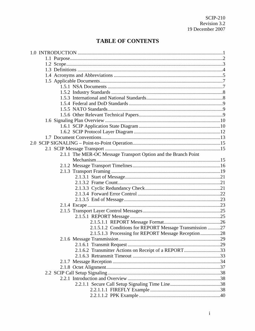
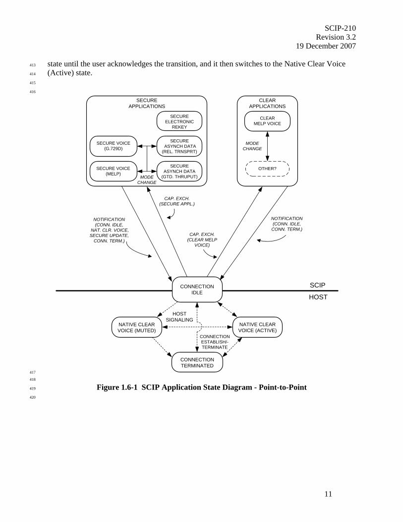
1.6.1 SCIP Application State Diagram 398
399
Figure 1.6-1 provides a high level conceptual application state diagram of a terminal that 400
incorporates SCIP signaling. 401
402
The terminal starts in a Connection Terminated state in which there is no communication path to 403
the far end. Before the signaling defined in this Signaling Plan may be executed, a clear data 404
path, which will be used to carry the SCIP messages, must be established between the two ends. 405
The state in which such a clear data path exists, but over which no SCIP application signaling is 406
in process, is known as Connection Idle. (Note that while the term “Connection Idle” is used to 407
name this state in this Signaling Plan, it is likely that a different name will be used for it in 408
documents that define the native signaling of the terminal.) Of course the native signaling in the 409
terminal may be used to invoke other underlying “native” functions (e.g., Native Clear Voice) as 410
well. When a terminal transitions from a secure application to Native Clear Voice, the user must 411
acknowledge the transition. Therefore, the terminal remains in the Native Clear Voice (Muted) 412
SCIP-210 Revision 3.2
19 December 2007
11
state until the user acknowledges the transition, and it then switches to the Native Clear Voice 413
(Active) state. 414
415
416
SCIP
HOSTCONNECTION
IDLE
HOSTSIGNALING
CONNECTIONESTABLISH/-TERMINATE
NATIVE CLEARVOICE (MUTED)
CONNECTIONTERMINATED
NATIVE CLEARVOICE (ACTIVE)
CLEARAPPLICATIONS
OTHER?
MODECHANGE
CLEARMELP VOICE
CAP. EXCH.(CLEAR MELP
VOICE)
SECUREAPPLICATIONS
MODECHANGE
SECURE VOICE(MELP)
SECURE VOICE(G.729D)
SECUREELECTRONIC
REKEY
SECUREASYNCH DATA
(GTD. THRUPUT)
SECURE ASYNCH DATA(REL. TRNSPRT)
CAP. EXCH.(SECURE APPL.)
NOTIFICATION(CONN. IDLE,
NAT. CLR. VOICE,SECURE UPDATE,
CONN. TERM.)
NOTIFICATION(CONN. IDLE,
CONN. TERM.)
417
418
Figure 1.6-1 SCIP Application State Diagram - Point-to-Point 419
420
SCIP-210 Revision 3.2 19 December 2007
12
SCIP applications can be accessed from Connection Idle. Standard SCIP clear voice 421
applications (of which only Clear MELP Voice is currently defined) are chosen using the first 422
SCIP call setup exchange, the Capabilities Exchange. In addition to the Capabilities Exchange, 423
further exchanges are required to negotiate the parameters for standard SCIP secure applications. 424
The choice of vendor unique SCIP applications also starts with a Capabilities Exchange, after 425
which either the standard SCIP call setup signaling or vendor defined signaling may be used. 426
Native functions may be executed directly from this state using native host signaling, or may be 427
chosen using the Capabilities Exchange (in which case control passes back to Connection Idle 428
and through Connection Idle to the chosen native function). 429
430
For changing between secure applications that use the same traffic key or between SCIP clear 431
applications, a Mode Change function is provided. Transitions to other applications are made by 432
returning to Connection Idle. If a transition from a SCIP application to a common native 433
function is desired, this is indicated in the Notification Message. If a transition to a SCIP mode 434
is desired, an ensuing Capabilities Exchange is executed. For vendor unique mode transitions, 435
the terminals may use the standard mechanisms defined in this Signaling Plan or they may use 436
vendor unique methods for executing the transitions. 437
438
To terminate the call from a standard SCIP application, a Notification Message is used to return 439
to Connection Idle with an indication that the underlying native mechanism be used to close the 440
underlying clear data path and return to the Connection Terminated state. 441
442
443
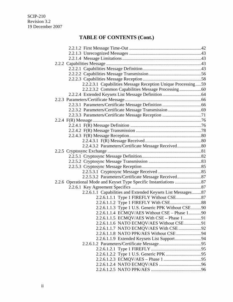
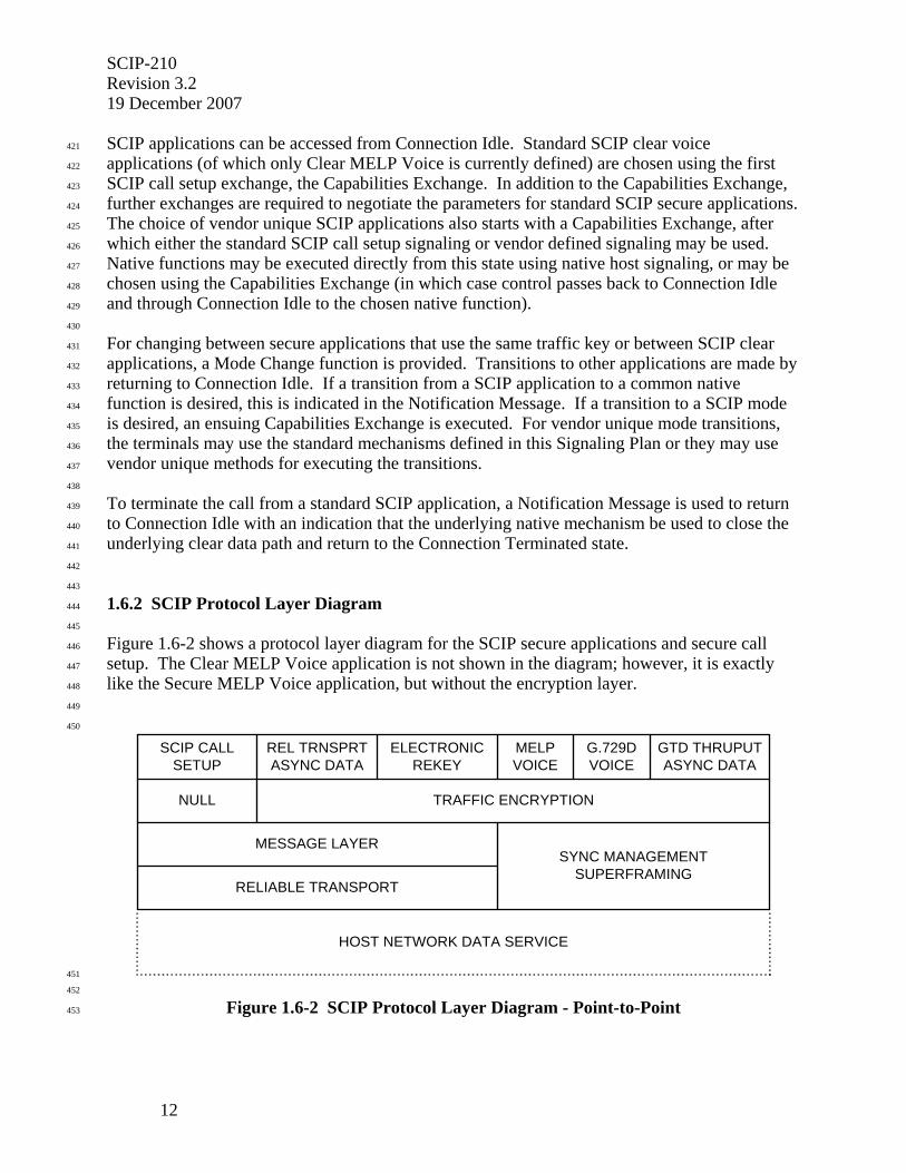
1.6.2 SCIP Protocol Layer Diagram 444
445
Figure 1.6-2 shows a protocol layer diagram for the SCIP secure applications and secure call 446
setup. The Clear MELP Voice application is not shown in the diagram; however, it is exactly 447
like the Secure MELP Voice application, but without the encryption layer. 448
449
450
SCIP CALLSETUP
REL TRNSPRTASYNC DATA
ELECTRONICREKEY
GTD THRUPUTASYNC DATA
MELPVOICE
G.729DVOICE
NULL TRAFFIC ENCRYPTION
MESSAGE LAYER
RELIABLE TRANSPORT
SYNC MANAGEMENTSUPERFRAMING
HOST NETWORK DATA SERVICE
451
452
Figure 1.6-2 SCIP Protocol Layer Diagram - Point-to-Point 453
SCIP-210 Revision 3.2
19 December 2007
13
454
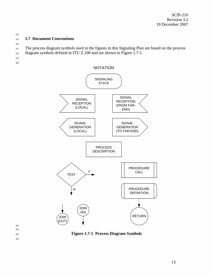
1.7 Document Conventions 455
456
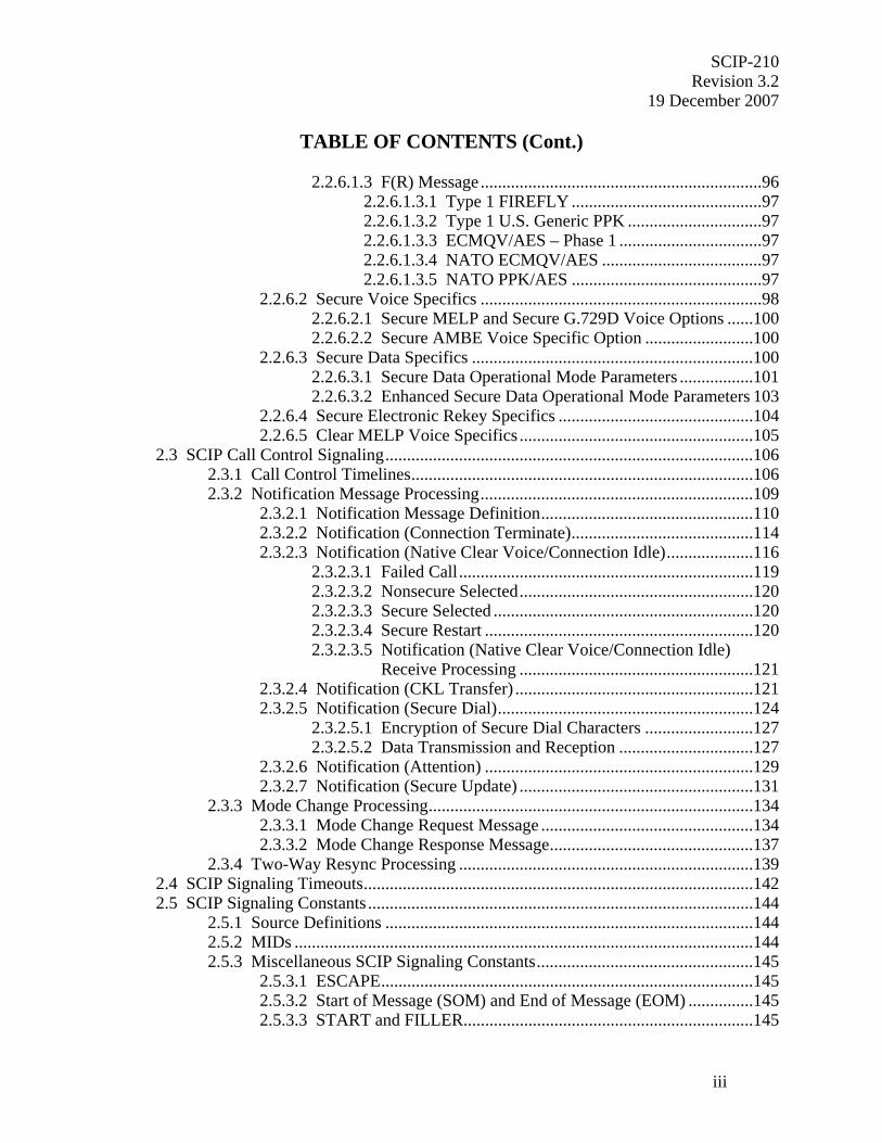
The process diagram symbols used in the figures in this Signaling Plan are based on the process 457
diagram symbols defined in ITU Z.100 and are shown in Figure 1.7-1. 458
459
460
NOTATION
SIGNALINGSTATE
SIGNALRECEPTION(FROM FAR-
END)
SIGNALRECEPTION
(LOCAL)
SIGNALGENERATION(TO FAR-END)
SIGNALGENERATION
(LOCAL)
PROCESSDESCRIPTION
Y
N
TEST
JOIN(IN)
JOIN(OUT)
PROCEDURECALL
PROCEDUREDEFINITION
RETURN
461
462
Figure 1.7-1 Process Diagram Symbols 463
464

SCIP-210 Revision 3.2 19 December 2007
14
465
466
467
468
469
470
471
472
473
474
475
476
477
478
479
480
481
482
483
484
485
THIS PAGE INTENTIONALLY LEFT BLANK. 486
487
488
SCIP-210 Revision 3.2
19 December 2007
15
489
2.0 SCIP SIGNALING – Point-to-Point Operation 490
491
This section defines the SCIP call setup and control signaling for point-to-point operation. 492
Section 2.1 specifies SCIP Transport Layer signaling, message framing, Transport Layer 493
messages, and the Transport Layer protocol rules. Section 2.2 specifies call setup signaling 494
including the Capabilities Exchange, which is always required, and the Parameters/Certificate 495
Exchange, F(R) Exchange, and Cryptosync Exchange, which are used to invoke a SCIP secure 496
application. Section 2.3 specifies the SCIP call control signaling including the Notification 497
Message, the Mode Change exchange, and the Two-Way Resync exchange. Section 2.4 498
specifies SCIP signaling timeouts, and Section 2.5 specifies signaling constants. 499
500
501
2.1 SCIP Message Transport 502
503
The SCIP MER message transport incorporates a number of error control mechanisms to 504
facilitate reliable delivery of signaling messages to the far-end terminal. Signaling transmissions 505
start with a Start of Message (SOM) and end with an End of Message (EOM) pattern and will be 506
referred to herein as “frame groups”. A frame group is composed of frames, each of which is 507
protected by a binary BCH code used for forward error correction (FEC) and a cyclic 508
redundancy check (CRC) code. Recovery from transmission errors that cannot be corrected by 509
the FEC is provided through the use of a combination of positive acknowledgment and selective 510
reject on a frame-by-frame basis. A Retransmission Timer provides protection for the cases 511
where an entire frame group is lost or does not arrive at the far-end terminal in a recognizable 512
form. Finally, a sliding window function, 127 frames in length, is used to control transmissions. 513
514
515
2.1.1 The MER-OC Message Transport Option and the Branch Point Mechanism 516
517
Sections 2.1.2 through 2.1.8 specify a MER message transport that all SCIP terminals must 518
implement. Additionally, alternate MER-OC message transports may be defined and 519
implemented. 520
521
If a developer chooses to implement a MER-OC message transport, a timeout based branch 522
transport mechanism must also be implemented. The timer shall be started after an end-to-end 523
connection has been established. Through the branch transport mechanism, the MER-OC 524
terminal shall fall back to the MER message transport unless it can determine, prior to the 525
expiration of the timeout, that the far-end terminal will successfully establish a compatible MER-526
OC mode. For human factors reasons, the MER-OC timeout should be kept as short as possible 527
but shall be long enough to be compatible with establishing the fallback MER message transport 528
prior to the expiration of the First Message Timer (see Section 2.4). 529
530
Note that, except for the extra delay, a MER-only terminal should be unaware of the far end's 531
attempt to establish a MER-OC transport. Note also that two terminals have a second chance to 532
establish a compatible MER-OC transport by offering such developer defined Operational 533

SCIP-210 Revision 3.2 19 December 2007
16
Modes as part of the Capabilities Exchange. MER-OC message transports are not further 534
defined in this document. 535
536
537
2.1.2 Message Transport Timelines 538
539
Throughout this document, references are made to “framed” and “full bandwidth” traffic. In the 540
context of SCIP-210, “framed” traffic refers to traffic that is formatted with the framing 541
information shown in Figure 2.1-2, starting with a SOM and ending with an EOM. In contrast, 542
“full bandwidth” traffic refers to application traffic that is transmitted with only sync 543
management information added as specified in Sections 3.3 and 3.4.2. It does not include a 544
leading SOM and a trailing EOM, although it should be noted that there may be other layers of 545
framing provided by the underlying network. Full bandwidth traffic is always preceded by the 546
START pattern. 547
548
It should also be noted that the transmit and receive channels of a terminal operate 549
independently. This means that if a terminal receives a START, its receive channel will be in 550
full bandwidth traffic, but its transmit channel will not be in full bandwidth traffic until it 551
transmits a START. The result is that during transition periods of entering or exiting full 552
bandwidth traffic, a terminal may in fact be operating with both framed and full bandwidth 553
traffic. 554
555
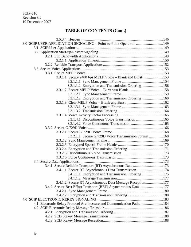
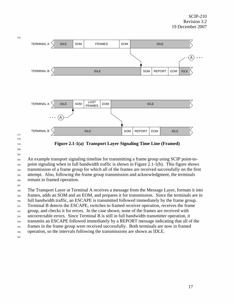
An example transport signaling timeline for transmitting a frame group using SCIP point-to-556
point signaling when in framed traffic is shown in Figure 2.1-1(a). This figure shows 557
transmission of a frame group for which some of the frames are received with uncorrectable 558
errors. The frames received with uncorrectable errors are retransmitted and received correctly on 559
the second attempt. 560
561
The Transport Layer at Terminal A receives a message from the Message Layer, formats it into 562
frames, adds an SOM and an EOM, and transmits the frame group. Terminal B receives the 563
frame group and executes error detection and correction. In the case shown, some of the frames 564
are received with uncorrectable errors; therefore, Terminal B formats a REPORT message 565
identifying the frames that contained uncorrectable errors and transmits it. Upon receiving the 566
REPORT message, Terminal A formats the frames that were not received correctly into a new 567
frame group by adding an SOM and an EOM and transmits it. Terminal B receives this frame 568
group, decodes the frames, and finds no uncorrectable errors. Therefore, Terminal B sends a 569
REPORT message indicating that all of the frames contained in the original frame group have 570
been received correctly. The intervals between transmissions are shown as IDLE in Figure 2.1-571
1(a). This means there is no transmission of data by the SCIP application; however, 572
transmissions may occur on individual links related to handshaking performed by the underlying 573
channel protocols. 574
575
SCIP-210 Revision 3.2
19 December 2007
17
576
IDLEIDLE
IDLEIDLE
IDLEIDLE
IDLEIDLE SOMTERMINAL A EOM
SOM REPORT EOMTERMINAL B
TERMINAL A
TERMINAL B
SOM
SOM
EOM
EOM
LOSTFRAMES
REPORT
A . . .
A. . .
FRAMES
577
578
Figure 2.1-1(a) Transport Layer Signaling Time Line (Framed) 579
580
581
An example transport signaling timeline for transmitting a frame group using SCIP point-to-582
point signaling when in full bandwidth traffic is shown in Figure 2.1-1(b). This figure shows 583
transmission of a frame group for which all of the frames are received successfully on the first 584
attempt. Also, following the frame group transmission and acknowledgment, the terminals 585
remain in framed operation. 586
587
The Transport Layer at Terminal A receives a message from the Message Layer, formats it into 588
frames, adds an SOM and an EOM, and prepares it for transmission. Since the terminals are in 589
full bandwidth traffic, an ESCAPE is transmitted followed immediately by the frame group. 590
Terminal B detects the ESCAPE, switches to framed receiver operation, receives the frame 591
group, and checks it for errors. In the case shown, none of the frames are received with 592
uncorrectable errors. Since Terminal B is still in full bandwidth transmitter operation, it 593
transmits an ESCAPE followed immediately by a REPORT message indicating that all of the 594
frames in the frame group were received successfully. Both terminals are now in framed 595
operation, so the intervals following the transmissions are shown as IDLE. 596
597
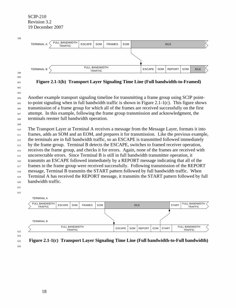
SCIP-210 Revision 3.2 19 December 2007
18
598
IDLE
IDLESOMTERMINAL A FRAMES EOM
SOM REPORT EOMTERMINAL B
FULL BANDWIDTHTRAFFIC ESCAPE
ESCAPEFULL BANDWIDTHTRAFFIC 599
600
Figure 2.1-1(b) Transport Layer Signaling Time Line (Full bandwidth-to-Framed) 601
602
603
Another example transport signaling timeline for transmitting a frame group using SCIP point-604
to-point signaling when in full bandwidth traffic is shown in Figure 2.1-1(c). This figure shows 605
transmission of a frame group for which all of the frames are received successfully on the first 606
attempt. In this example, following the frame group transmission and acknowledgment, the 607
terminals reenter full bandwidth operation. 608
609
The Transport Layer at Terminal A receives a message from the Message Layer, formats it into 610
frames, adds an SOM and an EOM, and prepares it for transmission. Like the previous example, 611
the terminals are in full bandwidth traffic, so an ESCAPE is transmitted followed immediately 612
by the frame group. Terminal B detects the ESCAPE, switches to framed receiver operation, 613
receives the frame group, and checks it for errors. Again, none of the frames are received with 614
uncorrectable errors. Since Terminal B is still in full bandwidth transmitter operation, it 615
transmits an ESCAPE followed immediately by a REPORT message indicating that all of the 616
frames in the frame group were received successfully. Following transmission of the REPORT 617
message, Terminal B transmits the START pattern followed by full bandwidth traffic. When 618
Terminal A has received the REPORT message, it transmits the START pattern followed by full 619
bandwidth traffic. 620
621
622
IDLESOM
TERMINAL A
EOM
SOM REPORT EOM
TERMINAL B
FULL BANDWIDTHTRAFFIC ESCAPE
ESCAPEFULL BANDWIDTHTRAFFIC
FULL BANDWIDTHTRAFFIC
FULL BANDWIDTHTRAFFICSTART
START
FRAMES
623
624
Figure 2.1-1(c) Transport Layer Signaling Time Line (Full bandwidth-to-Full bandwidth) 625
626
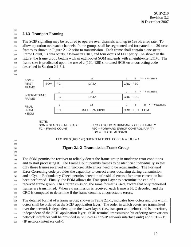
SCIP-210 Revision 3.2
19 December 2007
19
627
2.1.3 Transport Framing 628
629
The SCIP signaling may be required to operate over channels with up to 1% bit error rate. To 630
allow operation over such channels, frame groups shall be segmented and formatted into 20-octet 631
frames as shown in Figure 2.1-2 prior to transmission. Each frame shall contain a one-octet 632
Frame Count, 13 data octets, a two-octet CRC, and four octets of FEC parity. As shown in the 633
figure, the frame group begins with an eight-octet SOM and ends with an eight-octet EOM. The 634
frame size is predicated upon the use of a (160, 128) shortened BCH error correcting code 635
described in Section 2.1.3.4. 636
637
638
SOM +FIRSTFRAME
SOM FC DATA CRC FEC
INTERMEDIATEFRAME
FINALFRAME+ EOM
FC
FC
DATA CRC
CRC
FEC
FEC EOM
NOTE:SOM = START OF MESSAGE CRC = CYCLIC REDUNDANCY CHECK PARITYFC = FRAME COUNT FEC = FORWARD ERROR CONTROL PARITY
EOM = END OF MESSAGE
FEC USES (160, 128) SHORTENED BCH CODE, R = 0.8, t = 4
1 13 2 4 <---- # OCTETS
1 13 2 4
1 13 2 4
<---- # OCTETS
<---- # OCTETS
DATA + PADDING
8
8
639
640
Figure 2.1-2 Transmission Frame Group 641
642
643
The SOM permits the receiver to reliably detect the frame group in moderate error conditions 644
and to start processing it. The Frame Count permits frames to be identified individually so that 645
only those frames received with uncorrectable errors need to be retransmitted. The Forward 646
Error Correcting code provides the capability to correct errors occurring during transmission, 647
and a Cyclic Redundancy Check permits detection of residual errors after error correction has 648
been performed. Finally, the EOM allows the Transport Layer to determine the end of a 649
received frame group. On a retransmission, the same format is used, except that only requested 650
frames are transmitted. When a transmission is received, each frame is FEC decoded, and the 651
CRC is computed to determine if the frame contains uncorrectable errors. 652
653
The detailed format of a frame group, shown in Table 2.1-1, indicates how octets and bits within 654
octets shall be ordered at the SCIP application layer. The order in which octets are transmitted 655
over the network is dependent upon the lower layers (i.e., transport and below) and is, therefore, 656
independent of the SCIP application layer. SCIP terminal transmission bit ordering over various 657
network interfaces will be provided in SCIP-214 (non-IP network interface only) and SCIP-215 658
(IP network interface only). 659

SCIP-210 Revision 3.2 19 December 2007
20
660
Each message shall be partitioned into 13-octet data segments that are transmitted in order. 661
Octets 1 through 13 shall be placed in the first frame to be transmitted, octets 14 through 26 in 662
the second frame, etc. Any octets left over shall be transmitted in the Message Data field of the 663
final frame, which shall be padded out to 13 octets with padding octets having a value of 0x00. 664
Octets 1 - 13 of the message are placed in octets 10 - 22 of the frame group, octets 14 - 26 of the 665
message are placed in octets 30 - 42 of the frame group, etc. Bits within an octet of the message 666
are placed in the corresponding bit position of the frame, i.e., bit 1 of a message octet is placed in 667
bit 1 of the corresponding octet of the frame, etc. 668
669
670
Table 2.1-1 Frame Group Format 671
672
8 7 6 5 4 3 2 1 ⇐ Bits (msb) (lsb) Octets
SOM ⇓
0 1 1 1 1 1 1 0 1 • • • • • • • •
0 1 0 1 0 1 1 0 8
First Frame Frame Count
b7 b6 b5 b4 b3 b2 b1 b0 9 Message Data
X X X X X X X X 10 • • • • • • • •
X X X X X X X X 22 CRC
b8 b9 b10 b11 b12 b13 b14 b15-msb 23
b0-lsb b1 b2 b3 b4 b5 b6 b7 24
FEC
b24 b25 b26 b27 b28 b29 b30 b31-msb 25
• • • •
b0-lsb b1 b2 b3 b4 b5 b6 b7 28
• • • • • •
Mth Frame Frame Count
b7 b6 b5 b4 b3 b2 b1 b0 9+20(M-1) • • • • • • • •
X X X X X X X X 28+20(M-1)
EOM 1 0 0 0 0 0 0 1 9+20M
• • • • • • • •
1 0 1 0 1 0 0 1 16+20M M = Number of frames in the frame group 673
SCIP-210 Revision 3.2
19 December 2007
21
674
2.1.3.1 Start of Message 675
676
The Start of Message is a 64-bit pseudorandom sequence that begins each transmit frame group. 677
It is designed to allow acceptable detection performance in the anticipated error environments, 678
and to allow the receiver to determine the first bit of the first octet of a frame group. The SOM 679
value is specified in Table 2.5-3. The first frame shall immediately follow SOM transmission. 680
681
682
2.1.3.2 Frame Count 683
684
As shown in Figure 2.1-2, the first octet of each frame of a transmitted frame group shall contain 685
the Frame Count. The first frame of the first message transmitted, after initial entry or upon re-686
entry from a native mode, shall have Frame Count = 0x01. The Frame Count shall be 687
incremented for each subsequent frame transmitted (modulo 256 - with return to 0x01 after 688
0xFF) without regard to frame group boundaries. The Frame Count is not reset upon entry to or 689
exit from a SCIP application. In particular, it shall continue with the next value in sequence 690
following a transition from call setup signaling to a reliable transport application. For Transport 691
Layer control messages (REPORT), the Frame Count shall be set to 0x00 for all frames. This 692
identifies these messages as Transport Layer control messages. 693
694
Editor’s Note: Note that with a k-bit Frame Count, which provides a Frame Count range of 2k, the maximum window size is limited to 2k – 1 outstanding frames in order to prevent ambiguities. For this Signaling Plan, a window size of 128 frames outstanding would have been the result of a one-octet Frame Count field. However, Frame Count = 0x00 is reserved for Transport Layer control messages, thus a window size of 127 frames outstanding results. 695
696
2.1.3.3 Cyclic Redundancy Check 697
698
A Cyclic Redundancy Check shall be calculated over the Frame Count and Message Data fields 699
of each frame. The CRC shall be the North American standard CRC-16. Its generator 700
polynomial is P(x) = x16 + x15 + x2 + 1. The CRC shall be computed as follows. Let S(x) be the 701
polynomial representing the 112 bits (14 octets) of the transport frame beginning with the least 702
significant bit of the Frame Count and extending, in the order that the bits are transmitted, 703
through the most significant bit of the 13th octet of the Message Data field. The least significant 704
bit of the Frame Count is the coefficient of the highest degree term of S(x). The transmitted 705
CRC checksum, F(x), shall be the ones complement of the remainder of (x16S(x) + x112(x15 + x14 706
+ x13 + x12 + x11 + x10 + x9 + x8 + x7 + x6 + x5 + x4 + x3 + x2 + x + 1))/P(x). Note that multiplying 707
S(x) by x16 is equivalent to shifting S(x) 16 places to provide the space for the 16-bit CRC parity 708
bits, and adding x112(x15 + x14 + x13 + x12 + x11 + x10 + x9 + x8 + x7 + x6 + x5 + x4 + x3 + x2 + x + 1) 709
to x16S(x) is equivalent to inverting the first 16 bits of S(x). F(x) is then added to x16S(x) forming 710
the 128-bit transport frame, exclusive of the FEC field. The coefficient of the x15 term of F(x) 711
shall be transmitted immediately following the most significant bit of the 13th octet of the 712
Message Data field (see Table 2.1-1). 713
714
SCIP-210 Revision 3.2 19 December 2007
22
Editor's Note: Inverting the first 16 bits of S(x) can also be accomplished in a shift register implementation by setting the register to all “ones” initially. This permits the receiver to detect erroneous addition or deletion of zero bits at the leading end of S(x). Complementing the remainder permits the receiver to detect addition or deletion of trailing zeros that may appear as a result of errors. At the receiver, the shift register is again set to all “ones” initially, and the CRC is computed over the received S(x). If the computed and received CRC are the same value, there are no errors.
715
716
2.1.3.4 Forward Error Control 717
718
Forward error control shall be implemented with a four error correcting binary BCH code 719
shortened from a natural block length of 255. The block length of the code is 160; there are 128 720
information bits and 32 check bits per code block. The check bits are computed over the Frame 721
Count, Message Data, and CRC fields, that is, over 128 information bits or 16 octets. The 722
generator polynomial is 723
724
g(x) = x32 + x31 + x30 + x29 + x27 + x26 + x25 + x22 + x20 + x19 + x17 + x16 + x14 + x9 + x7 + x6 + x5 + 725
x4 + x3 + x2 + 1. 726
727
The check bits for the code shall be computed as follows. Let I(x) be the polynomial 728
representing the 128 bits to be encoded beginning with the least significant bit of the Frame 729
Count and extending, in the order that the bits are transmitted, through the most significant bit of 730
the second octet of the CRC field. The least significant bit of the Frame Count is the coefficient 731
of highest degree in I(x). The transmitted check bits, R(x), shall be calculated as 732
733
R(x) = (x32 I(x)) mod g(x). 734
735
Note that multiplying I(x) by x32 is equivalent to shifting I(x) 32 places to provide space for the 736
32 check bits. R(x) is then added to x32 I(x) to form the 160-bit BCH code word. The coefficient 737
of the x31 term of R(x) shall be transmitted immediately following the most significant bit of the 738
second octet of the CRC field (which contains the least significant bit of the CRC), and the least 739
significant bit of R(x) shall be transmitted last (see Table 2.1-1). 740
741
SCIP-210 Revision 3.2
19 December 2007
23
742
2.1.3.5 End of Message 743
744
The End of Message is a 64-bit pseudorandom sequence that immediately follows the final frame 745
of each transmitted frame group. It allows the receiving terminal to reliably detect the end of a 746
received frame group in the anticipated error environments. The EOM value is specified in 747
Table 2.5-3. Note that it is the bit-by-bit complement of the SOM. EOM shall be transmitted 748
following the final octet of the final frame of a frame group. 749
750
751
2.1.4 Escape 752
753
The ESCAPE sequence is a 256-bit pseudorandom sequence that allows reliable detection in the 754
background of full bandwidth traffic under expected channel conditions. The ESCAPE sequence 755
is used to permit the detection of transmitted frame groups that interrupt full bandwidth traffic. 756
The value of the ESCAPE sequence is specified in Table 2.5-3. 757
758
Transmit and receive processing for the ESCAPE are shown in Figure 2.1-3. When a terminal is 759
transmitting full bandwidth traffic (entry into full bandwidth traffic is described in Section 3), it 760
shall precede frame group transmissions with an ESCAPE. (Whether or not the far-end terminal 761
receiver has entered full bandwidth traffic is irrelevant. If it has entered full bandwidth traffic, 762
the ESCAPE is necessary. If it has not yet done so, the ESCAPE will be ignored, and the SOM 763
will be detected.) 764
765
When transmission of a frame group, which can be either a Call Control or a REPORT message, 766
is invoked during full bandwidth transmission, the terminal shall stop transmitting full 767
bandwidth traffic, transmit the ESCAPE sequence, and enable framing. The terminal shall then 768
format and transmit the requested frame group as specified in Section 2.1.6. (Note that the state 769
of the terminal’s receiver remains unchanged.) 770
771
A terminal that receives an ESCAPE sequence during full bandwidth reception shall enable 772
framed reception and process the incoming frame group as specified in Section 2.1.7. (Note that 773
the state of the terminal’s transmitter remains unchanged.) 774
775
776
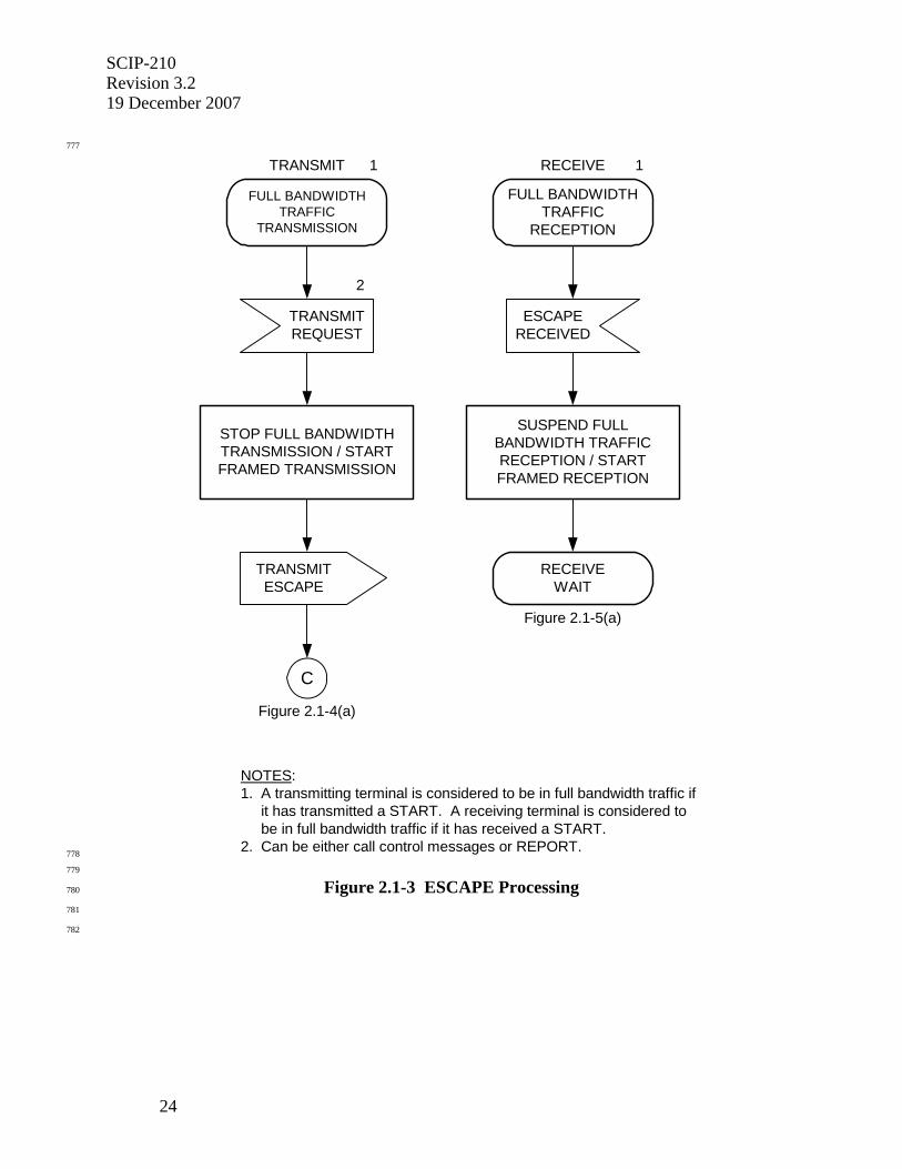
SCIP-210 Revision 3.2 19 December 2007
24
777
NOTES:1. A transmitting terminal is considered to be in full bandwidth traffic if it has transmitted a START. A receiving terminal is considered to be in full bandwidth traffic if it has received a START.2. Can be either call control messages or REPORT.
TRANSMITREQUEST
TRANSMITESCAPE
STOP FULL BANDWIDTHTRANSMISSION / STARTFRAMED TRANSMISSION
2
C
Figure 2.1-4(a)
FULL BANDWIDTHTRAFFIC
TRANSMISSION
ESCAPERECEIVED
FULL BANDWIDTHTRAFFIC
RECEPTION
SUSPEND FULLBANDWIDTH TRAFFICRECEPTION / STARTFRAMED RECEPTION
Figure 2.1-5(a)
RECEIVEWAIT
1 1TRANSMIT RECEIVE
778
779
Figure 2.1-3 ESCAPE Processing 780
781
782

SCIP-210 Revision 3.2
19 December 2007
25
783
2.1.5 Transport Layer Control Messages 784
785
Transport Layer control messages are messages that are exchanged between peer Transport 786
Layers and are not passed up to higher layers. They shall be transmitted with the Frame Count 787
field set to 0x00 to distinguish them from messages intended for higher layers. The REPORT 788
message is the only Transport Layer control message currently defined for SCIP signaling. The 789
REPORT message shall have a length of one frame. 790
791
792
2.1.5.1 REPORT Message 793
794
The REPORT message provides both the capability to acknowledge successful reception of 795
contiguous frames of received messages and the capability to selectively reject individual frames 796
of received messages. It contains an ACK’ed Frame Count field that corresponds to the last 797
consecutive message frame that was received successfully (either with no errors or with 798
correctable errors) and NAK’ed Frame fields corresponding to a maximum of seven message 799
frames that were lost (either not received or received with uncorrectable errors). Conditions 800
under which the REPORT message may be transmitted are specified in Section 2.1.5.1.2. 801
802
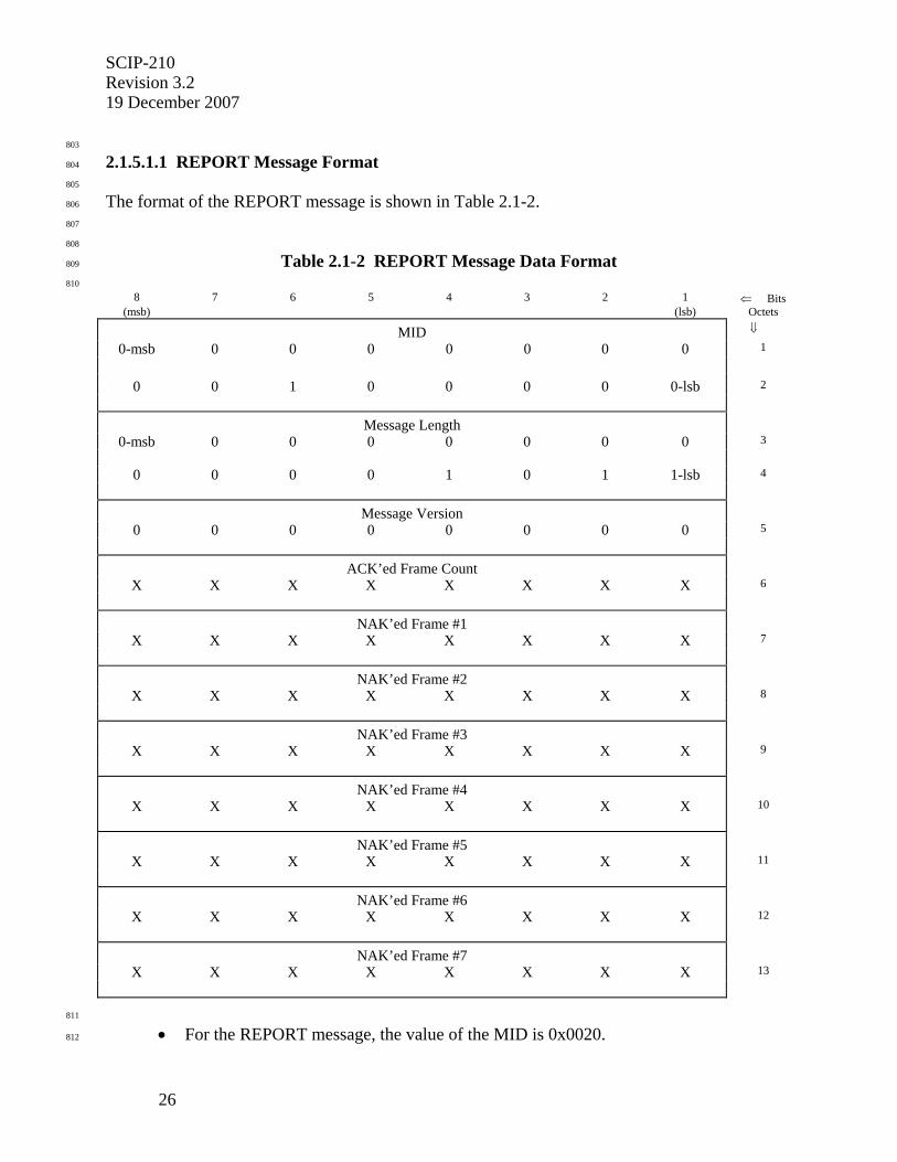
SCIP-210 Revision 3.2 19 December 2007
26
803
2.1.5.1.1 REPORT Message Format 804
805
The format of the REPORT message is shown in Table 2.1-2. 806
807
808
Table 2.1-2 REPORT Message Data Format 809
810
8 7 6 5 4 3 2 1 ⇐ Bits (msb) (lsb) Octets
MID ⇓
0-msb 0 0 0 0 0 0 0 1
0 0 1 0 0 0 0 0-lsb 2
Message Length
0-msb 0 0 0 0 0 0 0 3
0 0 0 0 1 0 1 1-lsb 4
Message Version
0 0 0 0 0 0 0 0 5
ACK’ed Frame Count
X X X X X X X X 6
NAK’ed Frame #1
X X X X X X X X 7
NAK’ed Frame #2
X X X X X X X X 8
NAK’ed Frame #3
X X X X X X X X 9
NAK’ed Frame #4
X X X X X X X X 10
NAK’ed Frame #5
X X X X X X X X 11
NAK’ed Frame #6
X X X X X X X X 12
NAK’ed Frame #7
X X X X X X X X 13
811
• For the REPORT message, the value of the MID is 0x0020. 812
SCIP-210 Revision 3.2
19 December 2007
27
• The Message Length contains the actual length of the message body (including the 813
length of the Message Length field itself but not including the length of the MID 814
field) in octets. The value of the field is an unsigned binary integer with the high 815
order bit being bit 8 of octet 3 and the low order bit being bit 1 of octet 4. It is always 816
set to 0x000B, since this is a fixed length message 817
• For the version of the REPORT message defined in this version of the Signaling Plan, 818
the value of the Message Version field is 0x00. 819
• The ACK’ed Frame Count field contains the Frame Count corresponding to the most 820
recent frame being acknowledged. 821
• The NAK’ed Frame fields contain the Frame Counts corresponding to up to seven 822
frames being negatively acknowledged (i.e., indicating that the frame was not 823
received successfully). If fewer than seven frames are to be NAK’ed, the remaining 824
(unused) NAK’ed Frame fields shall be set to 0x00. Also, if more than seven frames 825
are to be NAK’ed, multiple REPORT messages shall be transmitted. 826
827
828
2.1.5.1.2 Conditions for REPORT Message Transmission 829
830
The REPORT message shall be transmitted to indicate both successful (either error-free or with 831
correctable errors) reception of contiguous message frames and lost message frames (either not 832
received or received with uncorrectable errors). Except after a frame group containing Transport 833
Layer frames (i.e., frames with Frame Count 0x00) where it should not be sent, the REPORT 834
message shall be queued for transmission whenever an EOM or an unexpected SOM (indicating 835
that a previous EOM was lost) is received. In the transmit queue, REPORT messages have 836
priority over messages received from the higher layers and shall be transmitted first. 837
838
The ACK’ed Frame Count field shall be set to the Frame Count of the last frame of contiguous 839
frames received successfully. That is, the ACK’ed Frame Count indicates that all frames in the 840
window up to and including the indicated frame have been received successfully. In the case 841
where the first frame upon entry from Native Mode is received in error, the ACK’ed Frame 842
Count shall be set to 255 (i.e., to 0xFF). 843
844
If there are uncorrectable errors in the received frames (as detected by failure of FEC decoding 845
and/or CRC verification), the NAK’ed Frame fields shall be populated with their Frame Counts. 846
The NAK’ed Frame fields serve as a request to the far-end terminal for retransmission of the 847
indicated frames. The NAK’ed Frame fields shall be set to the Frame Counts of up to seven 848
frames either not received or received with uncorrectable errors. NAK’ed Frames included 849
within a REPORT message shall be in Frame Count sequence (e.g., frame 10 before frame 11, 850
frame 255 before the next frame 1) with the first Frame Count appearing in octet 7. If more than 851
seven frames are to be NAK’ed, an alternative to sending multiple REPORT messages that 852
provide the capability for NAK’ing the frames individually is to request that all frames, 853
beginning with the first frame to be NAK’ed, be retransmitted (i.e., request that the transmitter 854
go back to this frame and restart the transmission). This shall be accomplished by setting all 855
seven NAK’ed Frame fields in the REPORT message to the Frame Count of the frame at which 856
the retransmission is to start. 857
858
SCIP-210 Revision 3.2 19 December 2007
28
If more than seven frames are not received or are received with uncorrectable errors and multiple 859
REPORT messages are created and transmitted, the first REPORT message shall contain the 860
seven lowest (in Frame Count sequence) NAK’ed Frame Counts, the next REPORT message 861
shall contain the next seven lowest NAK’ed Frame Counts and so on until no NAK’ed Frames 862
remain. As in the case of a single REPORT message, the NAK’ed Frame Counts included 863
within each REPORT message shall be in Frame Count sequence. 864
865
If multiple REPORT messages are waiting in the transmit queue due to a busy transmitter, the 866
information may be consolidated and transmitted as a single REPORT message. Also, if frames 867
are received that have been previously acknowledged (indicating loss of a previous REPORT 868
message) and these frames are subsequently received with uncorrectable errors, they will not be 869
negatively acknowledged, but instead shall be acknowledged again and then discarded, as they 870
have previously been received successfully. 871
872
Editor’s Note: Note that while the specifications dictate when the REPORT must be sent, there are no restrictions concerning the transmission of additional REPORTs. Additional REPORTs may be sent at the discretion of the implementer. For example, a terminal may transmit a REPORT message prior to a timeout during which no frames are received. This allows frames received successfully to be acknowledged in the case where the final portion of a message, including the EOM, is lost during transmission and no subsequent transmissions occur during the timeout interval. The “retransmit starting at frame N” capability may be used to avoid a timeout, e.g., where a transmission disturbance has caused frame alignment to be lost, i.e., all received frames following the disturbance are failing FEC/CRC processing. 873
874
2.1.5.1.3 Processing for REPORT Message Reception 875
876
The NAK’ed Frame fields of the REPORT message indicate that specific frames have not been 877
received successfully. Note that the NAK’ed Frame fields may be empty (i.e., filled with all 878
0’s), in which case processing in addition to that specified below for the ACK’ed Frame Count is 879
not necessary. Upon or after receipt of one or more REPORT messages containing NAK’ed 880
Frame Counts, a terminal shall format one or more frame groups, as defined in Section 2.1.3, 881
containing only those frames indicated in the NAK’ed Frame fields, and shall transmit them to 882
the far end. Within the retransmission, frames shall be ordered in Frame Count sequence (e.g., 883
frame 10 before frame 11, frame 255 before the next frame 1). A terminal receiving a REPORT 884
message with all seven NAK’ed Frame fields set to the same value shall go back to the frame 885
indicated in the NAK’ed Frame fields and restart transmitting frame groups. The retransmission 886
timer (Section 2.1.6.3) shall be restarted (from its initial value) immediately upon transmission 887
of the EOM following the retransmitted (NAK’ed) frames. 888
889
The ACK’ed Frame Count field of the REPORT message indicates that all frames up to and 890
including the ACK’ed Frame Count have been received successfully by the far-end terminal. 891
The terminal receiving the REPORT can therefore move the start of its transmit window ahead to 892
the frame following the ACK’ed Frame Count, discarding the frame corresponding to the 893
ACK’ed Frame Count and all previous frames. Note that frames shall only be removed from the 894
transmit window after they have been acknowledged; that is, a REPORT message with an 895
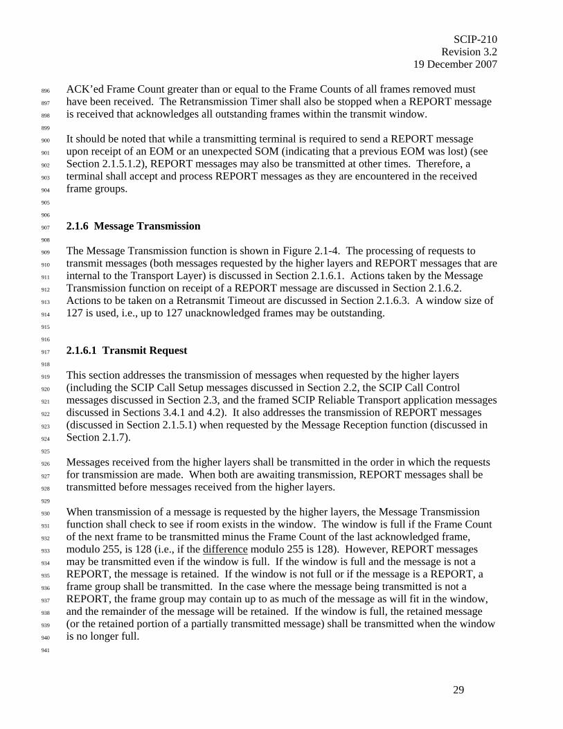
SCIP-210 Revision 3.2
19 December 2007
29
ACK’ed Frame Count greater than or equal to the Frame Counts of all frames removed must 896
have been received. The Retransmission Timer shall also be stopped when a REPORT message 897
is received that acknowledges all outstanding frames within the transmit window. 898
899
It should be noted that while a transmitting terminal is required to send a REPORT message 900
upon receipt of an EOM or an unexpected SOM (indicating that a previous EOM was lost) (see 901
Section 2.1.5.1.2), REPORT messages may also be transmitted at other times. Therefore, a 902
terminal shall accept and process REPORT messages as they are encountered in the received 903
frame groups. 904
905
906
2.1.6 Message Transmission 907
908
The Message Transmission function is shown in Figure 2.1-4. The processing of requests to 909
transmit messages (both messages requested by the higher layers and REPORT messages that are 910
internal to the Transport Layer) is discussed in Section 2.1.6.1. Actions taken by the Message 911
Transmission function on receipt of a REPORT message are discussed in Section 2.1.6.2. 912
Actions to be taken on a Retransmit Timeout are discussed in Section 2.1.6.3. A window size of 913
127 is used, i.e., up to 127 unacknowledged frames may be outstanding. 914
915
916
2.1.6.1 Transmit Request 917
918
This section addresses the transmission of messages when requested by the higher layers 919
(including the SCIP Call Setup messages discussed in Section 2.2, the SCIP Call Control 920
messages discussed in Section 2.3, and the framed SCIP Reliable Transport application messages 921
discussed in Sections 3.4.1 and 4.2). It also addresses the transmission of REPORT messages 922
(discussed in Section 2.1.5.1) when requested by the Message Reception function (discussed in 923
Section 2.1.7). 924
925
Messages received from the higher layers shall be transmitted in the order in which the requests 926
for transmission are made. When both are awaiting transmission, REPORT messages shall be 927
transmitted before messages received from the higher layers. 928
929
When transmission of a message is requested by the higher layers, the Message Transmission 930
function shall check to see if room exists in the window. The window is full if the Frame Count 931
of the next frame to be transmitted minus the Frame Count of the last acknowledged frame, 932
modulo 255, is 128 (i.e., if the difference modulo 255 is 128). However, REPORT messages 933
may be transmitted even if the window is full. If the window is full and the message is not a 934
REPORT, the message is retained. If the window is not full or if the message is a REPORT, a 935
frame group shall be transmitted. In the case where the message being transmitted is not a 936
REPORT, the frame group may contain up to as much of the message as will fit in the window, 937
and the remainder of the message will be retained. If the window is full, the retained message 938
(or the retained portion of a partially transmitted message) shall be transmitted when the window 939
is no longer full. 940
941

SCIP-210 Revision 3.2 19 December 2007
30
The frame group is formatted as specified in Section 2.1.3. An SOM is transmitted first. Then, 942
while the window constraint permits, message frames are transmitted, followed by the EOM. 943
Frame groups may contain frames from one or more messages. If an entire message does not fit 944
in the current window, that part of the message not transmitted is retained and shall be 945
transmitted when the window is no longer full. When frame transmission is stopped due to a full 946
window, the last frame transmitted shall be followed by an EOM. The next transmission shall 947
then begin with an SOM. Immediately upon transmission of the frame group EOM, unless the 948
message was a REPORT, the Retransmit Timer (Section 2.1.6.3) will be (re)initialized to its 949
initial value and (re)started so that the frames may be retransmitted if no REPORTs are received. 950
951
Editor’s Note: Note that although this specification dictates certain times when frame groups must be terminated (e.g., a full transmit window), other frame groups may be terminated at the transmitter’s discretion. A frame group may be any length > 1 frame. Any transmission must be a complete frame group. 952
If the transmission occurs subsequent to a transmitted START (i.e., during full bandwidth 953
traffic), the frame group will be preceded by an ESCAPE as specified in Section 2.1.4. 954
955
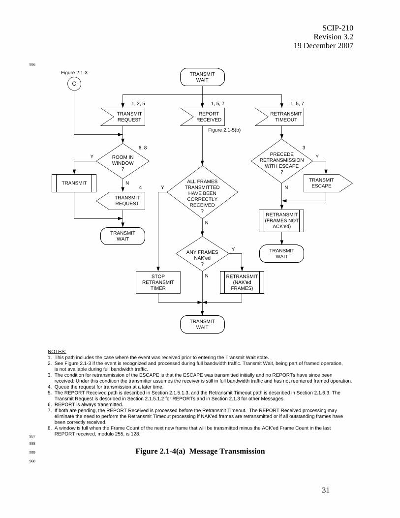
SCIP-210 Revision 3.2
19 December 2007
31
956
NOTES:1. This path includes the case where the event was received prior to entering the Transmit Wait state.2. See Figure 2.1-3 if the event is recognized and processed during full bandwidth traffic. Transmit Wait, being part of framed operation, is not available during full bandwidth traffic.3. The condition for retransmission of the ESCAPE is that the ESCAPE was transmitted initially and no REPORTs have since been received. Under this condition the transmitter assumes the receiver is still in full bandwidth traffic and has not reentered framed operation.4. Queue the request for transmission at a later time.5. The REPORT Received path is described in Section 2.1.5.1.3, and the Retransmit Timeout path is described in Section 2.1.6.3. The Transmit Request is described in Section 2.1.5.1.2 for REPORTs and in Section 2.1.3 for other Messages.6. REPORT is always transmitted.7. If both are pending, the REPORT Received is processed before the Retransmit Timeout. The REPORT Received processing may eliminate the need to perform the Retransmit Timeout processing if NAK'ed frames are retransmitted or if all outstanding frames have been correctly received.8. A window is full when the Frame Count of the next new frame that will be transmitted minus the ACK'ed Frame Count in the last REPORT received, modulo 255, is 128.
REPORTRECEIVED
1, 5, 7
Figure 2.1-5(b)
TRANSMITWAIT
ANY FRAMESNAK'ed
?
Y
NSTOPRETRANSMIT
TIMER
RETRANSMIT(NAK'ed
FRAMES)
TRANSMITWAIT
RETRANSMITTIMEOUT
1, 5, 7
RETRANSMIT(FRAMES NOT
ACK'ed)
PRECEDERETRANSMISSION
WITH ESCAPE?
N
TRANSMITWAIT
TRANSMITREQUEST
1, 2, 5
Figure 2.1-3
ROOM INWINDOW
?
Y
N
6, 8
4
C
TRANSMITREQUEST
TRANSMIT
TRANSMITWAIT
TRANSMITESCAPE
Y
3
ALL FRAMESTRANSMITTED
HAVE BEENCORRECTLYRECEIVED
?
Y
N
957
958
Figure 2.1-4(a) Message Transmission 959
960
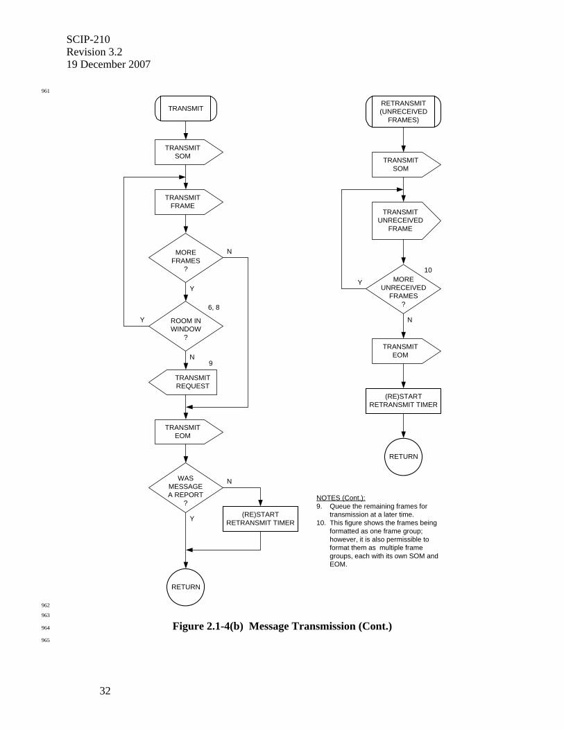
SCIP-210 Revision 3.2 19 December 2007
32
961
TRANSMITSOM
TRANSMIT
MOREFRAMES
?
Y
N
TRANSMITFRAME
ROOM INWINDOW
?
Y
N
TRANSMITREQUEST
WASMESSAGEA REPORT
?
Y
N
(RE)STARTRETRANSMIT TIMER
RETURN
TRANSMITEOM
RETRANSMIT(UNRECEIVED
FRAMES)
TRANSMITUNRECEIVED
FRAME
MOREUNRECEIVED
FRAMES?
Y
N
TRANSMITSOM
10
TRANSMITEOM
(RE)STARTRETRANSMIT TIMER
RETURN
NOTES (Cont.):9. Queue the remaining frames for transmission at a later time.10. This figure shows the frames being formatted as one frame group; however, it is also permissible to format them as multiple frame groups, each with its own SOM and EOM.
6, 8
9
962
963
Figure 2.1-4(b) Message Transmission (Cont.) 964
965
SCIP-210 Revision 3.2
19 December 2007
33
966
2.1.6.2 Transmitter Actions on Receipt of a REPORT 967
968
Upon receipt of a REPORT message, the Message Transmission function will proceed as 969
follows. 970
971
If all frames that have been transmitted are acknowledged by the REPORT, the Retransmit 972
Timer is stopped. 973
974
If frames are NAK’ed by the REPORT, a frame group containing the NAK’ed frames is 975
formatted as specified in Section 2.1.5.1.3 and is transmitted. An SOM is transmitted first. This 976
is followed by the NAK’ed frames and by an EOM. Immediately upon transmission of the frame 977
group EOM, the Retransmit Timer (Section 2.1.6.3) will be (re)initialized to its initial value and 978
(re)started so that the frames may again be transmitted if no REPORT is received. 979
980
Note that if the REPORT does not contain NAK’ed Frames and does not acknowledge all 981
outstanding frames, the Retransmit Timer is neither (re)initialized nor stopped. (For example, if 982
a terminal that has transmitted two frame groups receives a REPORT acknowledging the first of 983
the two groups, it does not stop the Retransmit Timer, since the second of the two groups has not 984
yet been acknowledged.) 985
986
Note also that if the window was full and the REPORT acknowledges frames that had not 987
previously been acknowledged, the window is now no longer full, and frames that previously 988
could not be transmitted may now be sent. (See Section 2.1.6.1.) 989
990
Editor’s Note: If multiple REPORT messages are received before the transmitter can act on them, the action taken by the transmitter can be based on combining the information contained in these REPORT messages. 991
992
2.1.6.3 Retransmit Timeout 993
994
In addition to the retransmission of NAK’ed frames described in Section 2.1.6.2, 995
unacknowledged frames are retransmitted on the expiration of the Retransmit Timer. 996
997
The Retransmit Timer is (re)started at initial transmission and at each retransmission. Upon 998
expiration of the Retransmit Timer, previously transmitted frames that have not yet been 999
acknowledged shall be formatted as a frame group (see Section 2.1.3) and shall be retransmitted. 1000
(An implementer may choose to transmit only a subset of the outstanding frames.) If one or 1001
more previous frame groups were transmitted preceded by an ESCAPE and no REPORTs have 1002
since been received for frames in those frame groups, the retransmission shall be preceded by an 1003
ESCAPE. 1004
1005
An SOM is transmitted first. The SOM is followed by one or more unacknowledged frames. 1006
Within the retransmission, frames shall be ordered in frame count sequence (e.g., frame 10 1007
before frame 11, frame 255 before the next frame 1). An EOM is then transmitted. Immediately 1008

SCIP-210 Revision 3.2 19 December 2007
34
upon transmission of the frame group EOM, the Retransmit Timer shall be (re)initialized to its 1009
initial value and shall be (re)started so that these frames may again be retransmitted if no 1010
REPORTs are received. The value to use when (re)initializing the Retransmit Timer is discussed 1011
in Section 2.4. 1012
1013
REPORT processing shall be performed before Retransmit Timeout processing if both are 1014
pending. If the REPORT processing results in the Retransmit Timer being "stopped" or 1015
(re)started, the Retransmit Timeout processing is not performed. 1016
1017
Editor’s Note: It is expected that an implementer will include logic to determine that transmissions are not getting through in spite of repeated retransmissions. This logic is left to the implementer's discretion. It is suggested that the action taken be Connection Terminate, though this is not required. 1018
1019
2.1.7 Message Reception 1020
1021
The Transport Layer Message Reception function is shown in Figure 2.1-5. 1022
1023
When the SOM is received, the receiver shall parse a 20-octet frame from the incoming data 1024
stream. The receiver may perform an FEC decode and shall use the CRC to verify that the frame 1025
was received correctly or that transmission errors were corrected during FEC decoding. 1026
1027
• If the CRC passes and the Frame Count is not zero (i.e., the message is not a Transport Layer 1028
control message) and is within the expected receive window, the frame shall be marked as 1029
correctly received. Frames that are outside the expected receive window shall be discarded 1030
without any additional processing. The receive window extends from the frame following 1031
the current ACK’ed Frame Count, i.e., the frame following the last receive frame that has 1032
been acknowledged, through 127 frames ahead of the ACK’ed Frame Count. 1033
1034
• If the CRC passes and the Frame Count is zero (i.e., the message is a Transport Layer control 1035
message), the terminal shall determine if a REPORT has been received. Each message type 1036
is recognized by its MID. (See Section 2.1.5 for the formats of these messages.) If a 1037
REPORT has been received, processing continues as defined in Section 2.1.5.1.3. 1038
1039
If a REPORT has not been received, also if the CRC does not pass, the following received octets 1040
are checked for an EOM. If an EOM or another SOM does not follow, the receiver shall parse 1041
the next 20-octet frame and repeat the above processing. 1042
1043
Editor's Note: Note that the implementer may opt to consider a frame as being received incorrectly if FEC decoding is not successful. In this case, checking the CRC is not required.
1044
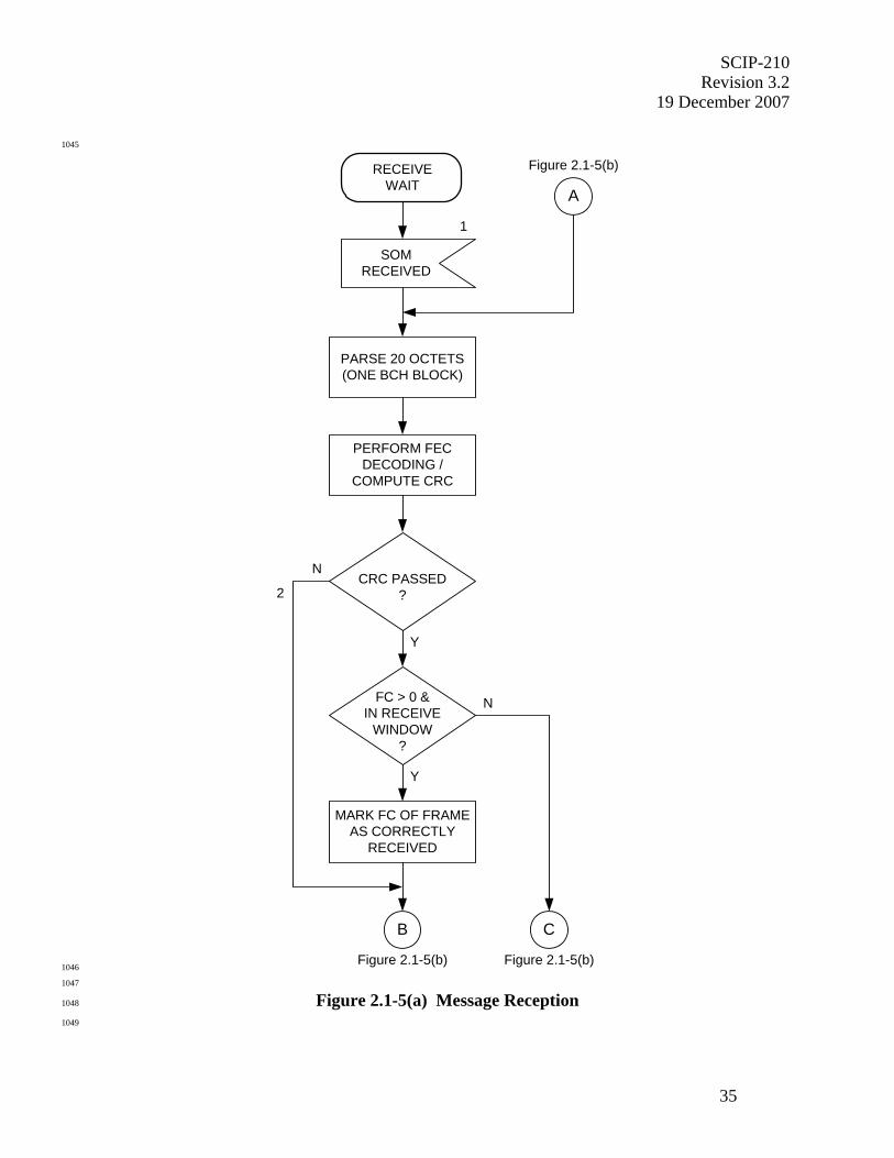
SCIP-210 Revision 3.2
19 December 2007
35
1045
RECEIVEWAIT
SOMRECEIVED
PARSE 20 OCTETS(ONE BCH BLOCK)
PERFORM FECDECODING /
COMPUTE CRC
1
MARK FC OF FRAMEAS CORRECTLY
RECEIVED
CRC PASSED?
Y
N
FC > 0 &IN RECEIVE
WINDOW?
A
Y
N
B
2
C
Figure 2.1-5(b)
Figure 2.1-5(b) Figure 2.1-5(b) 1046
1047
Figure 2.1-5(a) Message Reception 1048
1049
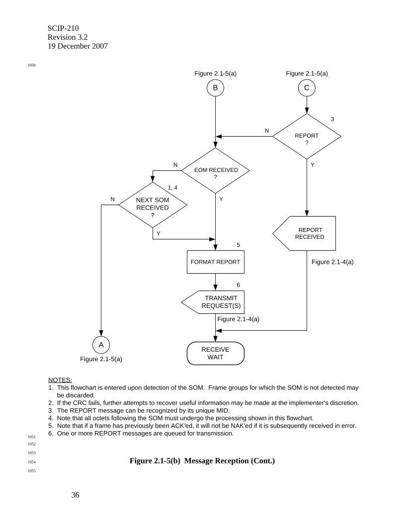
SCIP-210 Revision 3.2 19 December 2007
36
1050
3
REPORT?
N
Y
REPORTRECEIVED
Figure 2.1-4(a)
CB
EOM RECEIVED?
N
1, 4
NEXT SOMRECEIVED
?
Y
N Y
FORMAT REPORT
5
Figure 2.1-4(a)
6
TRANSMITREQUEST(S)
RECEIVEWAIT
A
Figure 2.1-5(a)
Figure 2.1-5(a) Figure 2.1-5(a)
NOTES:1. This flowchart is entered upon detection of the SOM. Frame groups for which the SOM is not detected may be discarded.2. If the CRC fails, further attempts to recover useful information may be made at the implementer's discretion.3. The REPORT message can be recognized by its unique MID.4. Note that all octets following the SOM must undergo the processing shown in this flowchart.5. Note that if a frame has previously been ACK'ed, it will not be NAK'ed if it is subsequently received in error.6. One or more REPORT messages are queued for transmission.
1051
1052
1053
Figure 2.1-5(b) Message Reception (Cont.) 1054
1055
SCIP-210 Revision 3.2
19 December 2007
37
1056
The receiver shall repeat the above process until either the EOM or the next SOM has been 1057
received. Upon receipt of either the EOM or the next SOM, the terminal will format and 1058
transmit a REPORT as specified in Section 2.1.5. Multiple REPORTs may be used, since each 1059
REPORT can identify only seven NAK’ed frames. 1060
1061
Editor's Note: A developer may implement a timer that resends a REPORT if the requested retransmissions are not received. The retransmit logic defined in this Signaling Plan is consistent both with implementations having such a timer and with implementations not having such a timer.
1062
If an EOM is received, the receiver waits for the next SOM. If an SOM is received, the receiver 1063
immediately starts processing the frames that follow the SOM. 1064
1065
Editor's Note: If a receiver is able to recognize and process frames in a frame group even when the SOM is not detected (e.g., by working backward from an EOM that is detected), this is permitted though it is not required.
1066
1067
2.1.8 Octet Alignment 1068
1069
The frame group and ESCAPE signaling are shown octet aligned and are expected to be 1070
transmitted octet aligned. However, the signaling may be carried on networks that do not 1071
preserve octet alignment. Therefore, the SCIP receiver shall be capable of recovering and 1072
processing the SCIP signaling shown herein even if it is not octet aligned when it is received. 1073
1074
SCIP-210 Revision 3.2 19 December 2007
38
1075
2.2 SCIP Call Setup Signaling 1076
1077
This section defines the SCIP call setup signaling. Section 2.2.1 provides an overview of this 1078
signaling. Section 2.2.2 describes the Capabilities Exchange which is always required. Sections 1079
2.2.3, 2.2.4 and 2.2.5 describe the Parameters/Certificate Exchange, the F(R) Exchange, and the 1080
Cryptosync Exchange which are used to establish a standard secure operational mode. The F(R) 1081
Exchange is not used for PPK processing. Section 2.2.6 provides a compilation of standard 1082
SCIP Operational Mode specific field definitions and values. 1083
1084
1085
2.2.1 Introduction and Overview 1086
1087
This section defines the SCIP point-to-point call setup signaling. It is assumed that an end-to-1088
end data channel has already been established, using the underlying channel protocols, by means 1089
outside the scope of this Signaling Plan. The signaling necessary to establish a SCIP point-to-1090
point Operational Mode is then executed over this data channel. The two SCIP terminals 1091
proceed, independently and in parallel, to execute the signaling defined in this section (except in 1092
a few specific places which are indicated through the use of Initiator/Responder terminology). 1093
1094
1095
2.2.1.1 Secure Call Setup Signaling Time Line 1096
1097
The following subsections provide examples of the overall flow for setting up a SCIP point-to-1098
point secure call. The secure call setup time lines are shown with no retransmissions. The 1099
examples begin with two terminals both transmitting Capabilities Messages. Once they are 1100
received, the Initiator and Responder roles are determined from the information contained in the 1101
Capabilities Messages. During IDLE periods, there is no transmission of bits by the SCIP 1102
application, though there may actually be bits on individual links related to handshaking 1103
performed by the underlying data channel protocols. 1104
1105
If a failure occurs at any point during SCIP call setup or if the user selects Nonsecure during call 1106
setup, the Native Clear Voice/Connection Idle signaling described in Section 2.3.2.3 will be 1107
executed. If the user goes "on-hook" without waiting for call setup to complete, the Connection 1108
Terminate signaling described in Section 2.3.2.2 will be executed. 1109
1110
1111
2.2.1.1.1 FIREFLY Example 1112
1113
A normal SCIP call setup using FIREFLY key is shown in Figure 2.2-1(a). One or more 1114
application messages are exchanged. The Capabilities Messages are always exchanged. If a 1115
standard secure Operational Mode is chosen, the Capabilities Exchange is followed by the 1116
exchange of optional Extended Keysets List Messages, Parameters/Certificate Messages, F(R) 1117
Messages, and Cryptosync Messages. These exchanges are described in Sections 2.2.2 through 1118
2.2.5. Under exception conditions, Notification Messages (described in Section 2.3.2) may also 1119
be exchanged. 1120
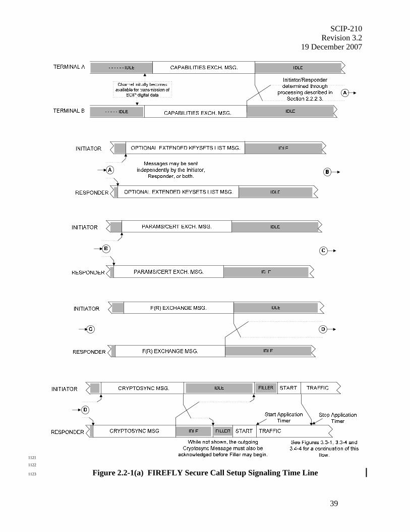
SCIP-210 Revision 3.2
19 December 2007
39
1121
1122
Figure 2.2-1(a) FIREFLY Secure Call Setup Signaling Time Line 1123
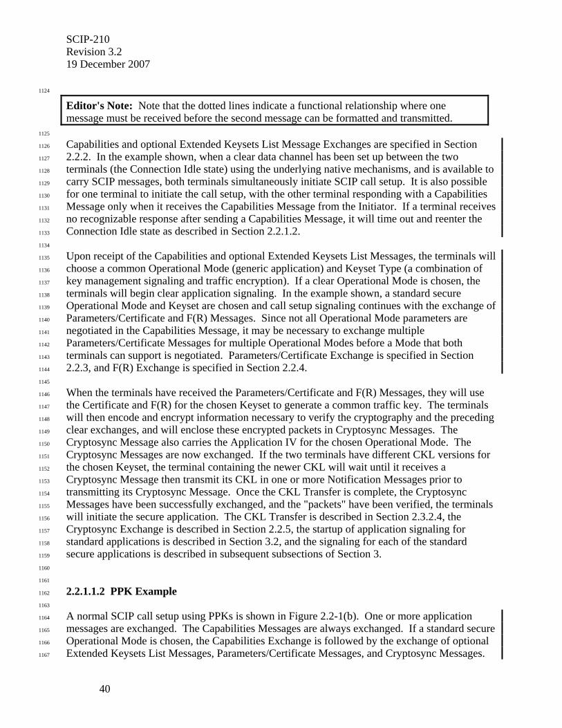
SCIP-210 Revision 3.2 19 December 2007
40
1124
Editor's Note: Note that the dotted lines indicate a functional relationship where one message must be received before the second message can be formatted and transmitted.
1125
Capabilities and optional Extended Keysets List Message Exchanges are specified in Section 1126
2.2.2. In the example shown, when a clear data channel has been set up between the two 1127
terminals (the Connection Idle state) using the underlying native mechanisms, and is available to 1128
carry SCIP messages, both terminals simultaneously initiate SCIP call setup. It is also possible 1129
for one terminal to initiate the call setup, with the other terminal responding with a Capabilities 1130
Message only when it receives the Capabilities Message from the Initiator. If a terminal receives 1131
no recognizable response after sending a Capabilities Message, it will time out and reenter the 1132
Connection Idle state as described in Section 2.2.1.2. 1133
1134
Upon receipt of the Capabilities and optional Extended Keysets List Messages, the terminals will 1135
choose a common Operational Mode (generic application) and Keyset Type (a combination of 1136
key management signaling and traffic encryption). If a clear Operational Mode is chosen, the 1137
terminals will begin clear application signaling. In the example shown, a standard secure 1138
Operational Mode and Keyset are chosen and call setup signaling continues with the exchange of 1139
Parameters/Certificate and F(R) Messages. Since not all Operational Mode parameters are 1140
negotiated in the Capabilities Message, it may be necessary to exchange multiple 1141
Parameters/Certificate Messages for multiple Operational Modes before a Mode that both 1142
terminals can support is negotiated. Parameters/Certificate Exchange is specified in Section 1143
2.2.3, and F(R) Exchange is specified in Section 2.2.4. 1144
1145
When the terminals have received the Parameters/Certificate and F(R) Messages, they will use 1146
the Certificate and F(R) for the chosen Keyset to generate a common traffic key. The terminals 1147
will then encode and encrypt information necessary to verify the cryptography and the preceding 1148
clear exchanges, and will enclose these encrypted packets in Cryptosync Messages. The 1149
Cryptosync Message also carries the Application IV for the chosen Operational Mode. The 1150
Cryptosync Messages are now exchanged. If the two terminals have different CKL versions for 1151
the chosen Keyset, the terminal containing the newer CKL will wait until it receives a 1152
Cryptosync Message then transmit its CKL in one or more Notification Messages prior to 1153
transmitting its Cryptosync Message. Once the CKL Transfer is complete, the Cryptosync 1154
Messages have been successfully exchanged, and the "packets" have been verified, the terminals 1155
will initiate the secure application. The CKL Transfer is described in Section 2.3.2.4, the 1156
Cryptosync Exchange is described in Section 2.2.5, the startup of application signaling for 1157
standard applications is described in Section 3.2, and the signaling for each of the standard 1158
secure applications is described in subsequent subsections of Section 3. 1159
1160
1161
2.2.1.1.2 PPK Example 1162
1163
A normal SCIP call setup using PPKs is shown in Figure 2.2-1(b). One or more application 1164
messages are exchanged. The Capabilities Messages are always exchanged. If a standard secure 1165
Operational Mode is chosen, the Capabilities Exchange is followed by the exchange of optional 1166
Extended Keysets List Messages, Parameters/Certificate Messages, and Cryptosync Messages. 1167
SCIP-210 Revision 3.2
19 December 2007
41
These exchanges are described in Sections 2.2.2, 2.2.3, and 2.2.5. Under exception conditions, 1168
Notification Messages (described in Section 2.3.2) may also be exchanged. 1169
1170
1171
TERMINAL A
TERMINAL B
- - - - - - IDLE
- - - - - IDLE CAPABILITIES EXCH. MSG.
IDLE
IDLE
CAPABILITIES EXCH. MSG.
AChannel initially becomes
available for transmission of SCIP digital data
INITIATOR
RESPONDER
IDLE
IDLE
OPTIONAL EXTENDED KEYSETS LIST MSG.
OPTIONAL EXTENDED KEYSETS LIST MSG.
A BMessages may be sent
independently by the Initiator, Responder, or both
INITIATOR
RESPONDER
IDLE
IDLE
PARAMS/CERT EXCH. MSG.
PARAMS/CERT EXCH. MSG.
B C
INITIATOR
RESPONDER
CRYPTOSYNC MSG.
CRYPTOSYNC MSG
FILLER
FILLER
START
START
TRAFFIC
TRAFFIC
C
See Figures 3.3-1, 3.3-4 and 3.4-4 for a continuation of this
flow.
IDLE
IDLE
While not shown, the outgoing Cryptosync Message must also be
acknowledged before Filler may begin.
Start Application Timer
Stop Application Timer
Initiator/Responder determined through
processing described in Section 2.2.2.3.
1172
1173
Figure 2.2-1(b) PPK Secure Call Setup Signaling Time Line 1174

SCIP-210 Revision 3.2 19 December 2007
42
1175
1176
Editor's Note: Note that the dotted lines indicate a functional relationship where one message must be received before the second message can be formatted and transmitted.
1177
Capabilities and optional Extended Keysets List Message Exchanges are specified in Section 1178
2.2.2. In the example shown, when a clear data channel has been set up between the two 1179
terminals (the Connection Idle state) using the underlying native mechanisms, and is available to 1180
carry SCIP messages, both terminals simultaneously initiate SCIP call setup. It is also possible 1181
for one terminal to initiate the call setup, with the other terminal responding with a Capabilities 1182
Message only when it receives the Capabilities Message from the Initiator. If a terminal receives 1183
no recognizable response after sending a Capabilities Message, it will time out and reenter the 1184
Connection Idle state as described in Section 2.2.1.2. 1185
1186
Upon receipt of the Capabilities and optional Extended Keysets List Messages, the terminals will 1187
choose a common Operational Mode (generic application) and Keyset Type (in this case, a PPK 1188
is chosen). If a clear Operational Mode is chosen, the terminals will begin clear application 1189
signaling. In the example shown, a standard secure Operational Mode and PPK Keyset are 1190
chosen and call setup signaling continues with the exchange of Parameters/Certificate Messages. 1191
Since not all Operational Mode parameters are negotiated in the Capabilities Message, it may be 1192
necessary to exchange multiple Parameters/Certificate Messages for multiple Operational Modes 1193
before a Mode that both terminals can support is negotiated. Parameters/Certificate Exchange is 1194
specified in Section 2.2.3. 1195
1196
When the terminals have received the Parameters/Certificate Messages, they will encode and 1197
encrypt information necessary to verify the cryptography and the preceding clear exchanges, and 1198
will enclose these encrypted packets in Cryptosync Messages. The Cryptosync Message also 1199
carries the Application IV for the chosen Operational Mode. The Cryptosync Messages are now 1200
exchanged. Once the Cryptosync Messages have been successfully exchanged, and the 1201
"packets" have been verified, the terminals will initiate the secure application. The Cryptosync 1202
Exchange is described in Section 2.2.5, the startup of application signaling for standard 1203
applications is described in Section 3.2, and the signaling for each of the standard secure 1204
applications is described in subsequent subsections of Section 3. 1205
1206
1207
2.2.1.2 First Message Time-Out 1208
1209
A First Message Timer is started when the Capabilities Message is transmitted (see Section 1210
2.2.2). This timer enables the terminal to time out should the far end not respond with a message 1211
that is recognizable as a SCIP message. Should this timer expire, the terminal shall execute the 1212
Failed Call logic defined in Section 2.3.2.3.1, with an Information Code of SCIP response not 1213
received, to return to Connection Idle state. 1214
1215
SCIP-210 Revision 3.2
19 December 2007
43
1216
2.2.1.3 Unrecognized Messages 1217
1218
In the case where a terminal receives an unrecognized message, the terminal may silently discard 1219
it or invoke either the Failed Call or Connection Terminate options as defined in Section 2.3. If 1220
the decision is to silently discard the message, the terminal shall remain in the same signaling 1221
state as prior to receiving it. 1222
1223
1224
2.2.1.4 Message Limitations 1225
1226
To ensure interoperability, terminals implementing SCIP-210, Rev. 3.2 or later shall send SCIP 1227
Call Setup and Notification Messages (excluding CKL Transfer) with a message limitation of 1228
1024 octets, except when the ability to send longer messages has been defined and negotiated. 1229
Note that this message limitation is on the total message length; no additional limitations are 1230
imposed on the length of variable length fields within these messages. Note that if a terminal 1231
must include a very long Keysets List in the Capabilities Message that causes the Capabilities 1232
Message to surpass this message length limitation, the optional Extended Keysets List Messages 1233
must be used (see Section 2.2.2.4). All terminals implementing SCIP-210, Rev 3.2 or later shall 1234
be capable of receiving SCIP Call Setup and Notification Messages (excluding CKL Transfer) 1235
with a total message length of at least 1024 octets. 1236
1237
If the terminals offer multiple Operational Modes in the Capabilities Messages and the 1238
Parameters/Certificate Messages resulting from the chosen Operational Mode do not have 1239
compatible Parameters, the terminals will continue to negotiate Operational Modes (see Section 1240
2.2.2.3.2) and transmit Parameters/Certificate Messages until either compatible Parameters are 1241
identified or Failed Call processing is executed. A terminal shall be capable of receiving at least 1242
three Parameters/Certificate Messages resulting from Operational Mode negotiations. Terminals 1243
may send more than three Parameters/Certificate Messages; however, interoperability is not 1244
guaranteed if more than three Parameters/Certificate Messages are sent. 1245
1246
1247
2.2.2 Capabilities Message 1248
1249
The first step in SCIP Call Setup is the exchange of Capabilities Messages. This exchange 1250
permits the terminals to negotiate a clear or secure Operational Mode which both support. For 1251
secure Operational Modes it also permits the terminals to choose compatible Keysets for which 1252
Credentials will be subsequently exchanged. 1253
1254
1255
2.2.2.1 Capabilities Message Definition 1256
1257
The format of the Capabilities Message is shown in Table 2.2-1. The Version 0 Capabilities 1258
Message contains the fields shown in Table 2.2-1(a) and Table 2.2-1(b), i.e., through the optional 1259
Keysets List field. The Version 1 or higher additions, shown in Table 2.2-1(c), begin with the 1260
Security Data Length field. 1261
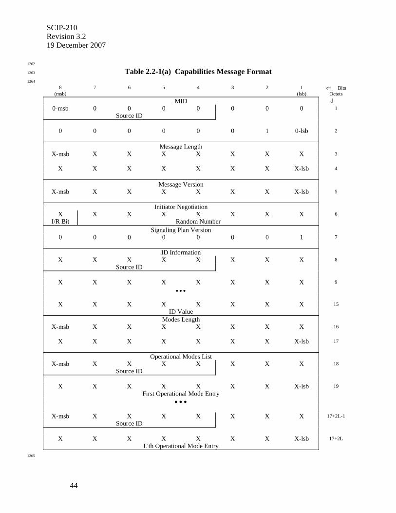
SCIP-210 Revision 3.2 19 December 2007
44
1262
Table 2.2-1(a) Capabilities Message Format 1263
1264
8 7 6 5 4 3 2 1 ⇐ Bits (msb) (lsb) Octets
MID ⇓ 0-msb 0 0 0 0 0 0 0 1
Source ID
0 0 0 0 0 0 1 0-lsb 2
Message Length
X-msb X X X X X X X 3
X X X X X X X X-lsb 4
Message Version
X-msb X X X X X X X-lsb 5
Initiator Negotiation X X X X X X X X 6
I/R Bit Random Number
Signaling Plan Version
0 0 0 0 0 0 0 1 7
ID Information
X X X X X X X X 8 Source ID
X X X X X X X X 9
• • •
X X X X X X X X 15
ID Value
Modes Length
X-msb X X X X X X X 16
X X X X X X X X-lsb 17
Operational Modes List
X-msb X X X X X X X 18 Source ID
X X X X X X X X-lsb 19
First Operational Mode Entry
• • •
X-msb X X X X X X X 17+2L-1 Source ID
X X X X X X X X-lsb 17+2L L'th Operational Mode Entry
1265
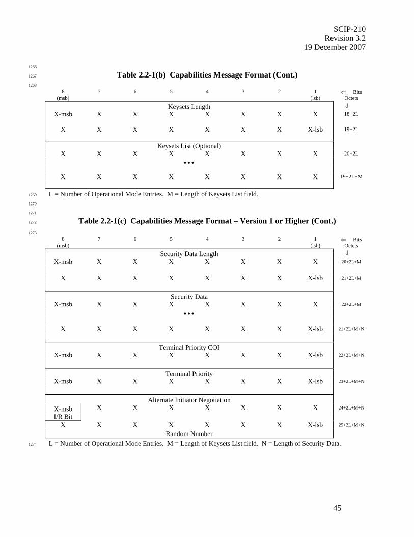
SCIP-210 Revision 3.2
19 December 2007
45
1266
Table 2.2-1(b) Capabilities Message Format (Cont.) 1267
1268
8 7 6 5 4 3 2 1 ⇐ Bits (msb) (lsb) Octets
Keysets Length ⇓ X-msb X X X X X X X 18+2L
X X X X X X X X-lsb 19+2L
Keysets List (Optional)
X X X X X X X X 20+2L
• • •
X X X X X X X X 19+2L+M
L = Number of Operational Mode Entries. M = Length of Keysets List field. 1269
1270
1271
Table 2.2-1(c) Capabilities Message Format – Version 1 or Higher (Cont.) 1272
1273 8 7 6 5 4 3 2 1 ⇐ Bits
(msb) (lsb) Octets Security Data Length ⇓
X-msb X X X X X X X 20+2L+M
X X X X X X X X-lsb 21+2L+M
Security Data
X-msb X X X X X X X 22+2L+M
• • •
X X X X X X X X-lsb 21+2L+M+N
Terminal Priority COI
X-msb X X X X X X X-lsb 22+2L+M+N
Terminal Priority
X-msb X X X X X X X-lsb 23+2L+M+N
Alternate Initiator Negotiation
X-msb X X X X X X X 24+2L+M+N
I/R Bit
X X X X X X X X-lsb 25+2L+M+N
Random Number
L = Number of Operational Mode Entries. M = Length of Keysets List field. N = Length of Security Data. 1274

SCIP-210 Revision 3.2 19 December 2007
46
1275
• For the Capabilities Message the value of the MID is 0x0002. 1276
• The Message Length shall contain the actual length of the message body (including 1277
the length of the Message Length field itself but not including the length of the MID 1278
field) in octets. The value of the field shall be an unsigned binary integer with the 1279
high order bit being bit 8 of octet 3 and the low order bit being bit 1 of octet 4. 1280
• The Message Version field shall be an unsigned binary integer with the high order bit 1281
being bit 8 and the low order bit being bit 1. 1282
1283
Editor's Note: A later version message than what is implemented in a terminal can be processed by discarding the newer information; i.e., changes must be made so that the message is backwardly compatible. This applies to all messages.
1284
A terminal in the Interoperable Terminal Priority COI, defined in Table 2.2-3(c), 1285
shall set the Initiator Negotiation field as follows. If the terminal has the Standard 1286
Terminal Priority (see Table 2.2-3(d)), or if it transmits a Version 0 Capabilities 1287
Message, the I/R Bit shall contain a 1 for an initiating terminal and a 0 for a 1288
responding terminal. The lower 7 bits shall contain a Random Number to resolve the 1289
case where both terminals initially view themselves as Initiators or Responders. If 1290
the terminal is transmitting a Version 1 or higher Capabilities Message and has a 1291
priority other than the Standard Terminal Priority, the Initiator Negotiation field shall 1292
be set to 0x00. 1293
• The value of Signaling Plan Version is 0x01 for this version of the Signaling Plan. 1294
• The ID Information field may be used to identify the terminal’s "security element". 1295
Content, processing, and format may vary from implementation to implementation. 1296
The high order 5 bits of the first octet identify a Source for the ID Information 1297
definition. Currently identified Source ID values are defined in Section 2.5.1. The 1298
terminal may set all bits of this field to 0 if no ID Information is to be transmitted. 1299
[Deviation Notice: The value 0x28 in octet 8 (i.e., Source ID = 0x05 in bits 4 - 8 and 1300
bits 1 - 3 set to zero) indicates the terminal requires special formatting for CKL 1301
Transfer (see Section 2.3.2.1).] 1302
• The Modes Length shall contain the actual length of the Operational Modes List (plus 1303
the length of the Modes Length field itself) in octets. The value of the field shall be 1304
an unsigned binary integer with the high order bit being bit 8 of octet 16 and the low 1305
order bit being bit 1 of octet 17. 1306
• The Operational Modes List shall contain one or more Operational Mode ID Entries. 1307
The Operational Mode ID Entries shall occur in order of preference; the ID of the 1308
preferred Operational Mode is placed in octets 18 and 19, the ID (if present) of the 1309
second choice Operational Mode is placed in octets 20 and 21, etc. The first entry on 1310
the Initiator's List which is also on the Responder's List is the Operational Mode 1311
chosen. Each Operational Mode ID in the Operational Modes List is 2 octets in 1312
length. The high order 5 bits of the first octet identify a Source for the Operational 1313
Mode definition. Currently identified Source ID values are defined in Section 2.5.1. 1314
The Source ID value plus the next 11 bits constitute an Operational Mode ID. The 1315
high order bit of the Operational Mode ID is placed in bit 8 of the first octet of the 1316

SCIP-210 Revision 3.2
19 December 2007
47
Operational Mode List entry and the low order bit of the Operational Mode ID is 1317
placed in bit 1 of the second octet of the Operational Mode List entry. Currently 1318
defined standard Operational Mode IDs are identified in Table 2.2-2. In order to 1319
prevent the Secure Electronic Rekey Operational Mode (0x000E) from being 1320
negotiated on calls between two standard SCIP devices, this mode shall only be 1321
offered by a SCIP Line Interface Terminal (SCIP-LIT); furthermore, this is the only 1322
Operational Mode that will be offered by a SCIP-LIT. 1323
1324
1325
Table 2.2-2 SCIP Standard Operational Modes 1326
1327
Operational Mode ID
Operational Mode Definition
0x0001 Secure Voice 0x0002 Secure Data 0x0003 Enhanced Secure Data 0x0004 Clear MELP Voice 0x0008 Native Clear Voice 0x000E Secure Electronic Rekey (offered only by the SCIP-LIT)
1328
• The Keysets Length shall contain the actual length of the Keysets List (plus the 1329
length of the Keysets Length field itself) in octets. The value of the field shall be an 1330
unsigned binary integer with the high order bit being bit 8 of the first octet of the field 1331
and the low order bit being bit 1 of the second octet of the field. 1332
• The Keysets List contains Keysets List Entries of the form given in Table 2.2-3(a). 1333
Each Keyset shall have a Keysets List Entry on the Keysets List. If only clear modes 1334
are offered, no Keysets need be listed on the Keysets List, i.e., the optional Keysets 1335
List need not be present. Keysets List Entries shall be in prioritized order per the 1336
rules defined by the controlling Terminal Priority COI. SCIP-230 or SCIP-232, 1337
Section 2.1.1.1.2; or SCIP-231, Section 2.1.1.2 defines the rules for the Standard 1338
Terminal Priority. Each entry shall consist of a Keyset Type, followed by a Keyset 1339
Parameters Length and Keyset Parameters (if parameters are defined) for a single 1340
Keyset. The length of the Keysets List is the sum of the lengths of the individual 1341
Keysets List Entries. 1342

SCIP-210 Revision 3.2 19 December 2007
48
1343
Table 2.2-3(a) Keysets List Entry - General Format 1344
1345
8 7 6 5 4 3 2 1 ⇐ Bits (msb) (lsb) Octets
Keyset Type ⇓
X-msb X X X X X X X 1
Source ID
X X X X X X X X-lsb 2
Keyset Parameters Length
X-msb X X X X X X X 3
X X X X X X X X-lsb 4
Keyset Parameters (Optional)
X X X X X X X X 5
• • •
X X X X X X X X 4+M
M = Length of Keyset Parameters field. 1346
1347
• The first field of a Keysets List Entry shall contain a Keyset Type. The high order 5 1348
bits of the first octet constitute a Source for the Keyset Type definition. Current 1349
Source IDs are defined in Section 2.5.1. The next 11 bits identify a unique Keyset 1350
Type within that Source. Currently defined values for Keyset Type are listed in 1351
Table 2.2-3(b). The high order bit of the Keyset Type is placed in bit 8 of the first 1352
octet, and the low order bit of the Keyset Type is placed in bit 1 of the second octet. 1353
• The second field of a Keysets List Entry shall contain a Keyset Parameters Length. 1354
This shall contain the actual length, in octets, of the Keyset Parameters (plus the 1355
length of the Keyset Parameters Length itself). The value of the field shall be an 1356
unsigned binary integer with the high order bit being bit 8 of octet 3 and the low 1357
order bit being bit 1 of octet 4. 1358
• The third field of a Keysets List Entry shall contain the Keyset Parameters. The 1359
Keyset Parameters field is variable length, and its contents are unique to each Keyset 1360
Type for which it is defined. For each standard Keyset Type, the format of the 1361
corresponding Keyset Parameters is defined in Section 2.2.6.1.1. This field is 1362
optional and is not present unless Keyset Parameters are defined for a given Keyset 1363
Type. 1364
1365
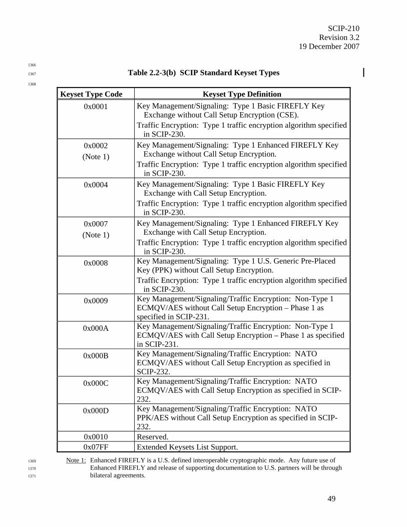
SCIP-210 Revision 3.2
19 December 2007
49
1366
Table 2.2-3(b) SCIP Standard Keyset Types 1367
1368
Keyset Type Code Keyset Type Definition 0x0001 Key Management/Signaling: Type 1 Basic FIREFLY Key
Exchange without Call Setup Encryption (CSE). Traffic Encryption: Type 1 traffic encryption algorithm specified
in SCIP-230. 0x0002 (Note 1)
Key Management/Signaling: Type 1 Enhanced FIREFLY Key Exchange without Call Setup Encryption.
Traffic Encryption: Type 1 traffic encryption algorithm specified in SCIP-230.
0x0004 Key Management/Signaling: Type 1 Basic FIREFLY Key Exchange with Call Setup Encryption.
Traffic Encryption: Type 1 traffic encryption algorithm specified in SCIP-230.
0x0007 (Note 1)
Key Management/Signaling: Type 1 Enhanced FIREFLY Key Exchange with Call Setup Encryption.
Traffic Encryption: Type 1 traffic encryption algorithm specified in SCIP-230.
0x0008 Key Management/Signaling: Type 1 U.S. Generic Pre-Placed Key (PPK) without Call Setup Encryption. Traffic Encryption: Type 1 traffic encryption algorithm specified
in SCIP-230. 0x0009 Key Management/Signaling/Traffic Encryption: Non-Type 1
ECMQV/AES without Call Setup Encryption – Phase 1 as specified in SCIP-231.
0x000A Key Management/Signaling/Traffic Encryption: Non-Type 1 ECMQV/AES with Call Setup Encryption – Phase 1 as specified in SCIP-231.
0x000B Key Management/Signaling/Traffic Encryption: NATO ECMQV/AES without Call Setup Encryption as specified in SCIP-232.
0x000C Key Management/Signaling/Traffic Encryption: NATO ECMQV/AES with Call Setup Encryption as specified in SCIP-232.
0x000D Key Management/Signaling/Traffic Encryption: NATO PPK/AES without Call Setup Encryption as specified in SCIP-232.
0x0010 Reserved. 0x07FF Extended Keysets List Support.
Note 1: Enhanced FIREFLY is a U.S. defined interoperable cryptographic mode. Any future use of 1369
Enhanced FIREFLY and release of supporting documentation to U.S. partners will be through 1370
bilateral agreements. 1371

SCIP-210 Revision 3.2 19 December 2007
50
1372
• The Security Data Length shall contain the actual length of the Security Data (plus 1373
the length of the Security Data Length field itself) in octets. The value of the field 1374
shall be an unsigned binary integer with the high order bit being bit 8 of the first octet 1375
of the field and the low order bit being bit 1 of the second octet of the field. 1376
• The Security Data field shall be populated per SCIP-230, Sections 2.1.1.3.1.5 and 1377
3.4.2, SCIP-231, Sections 2.1.2.1.2 and 3.2.2, or SCIP-232, Sections 2.1.1.3.1.5 and 1378
3.2.2.1. The Security Data's most significant bit (as defined in SCIP-230, Section 1379
3.1.2.1, SCIP-231, Section 3.1.2, or SCIP-232, Section 3.2.2.1) shall be placed in bit 1380
8 of the first octet, and its least significant bit shall be placed in bit 1 of the N'th octet. 1381
• The Terminal Priority COI is a unique value assigned to each Community of Interest 1382
that independently defines keyset selection rules. These rules are intended to provide 1383
a mechanism for SCIP devices to determine which terminal’s keyset ordering has 1384
priority. It identifies the community that controls the Terminal Priority and provides 1385
a mechanism for each community to control its terminals' priorities without 1386
international agreements. Currently defined Terminal Priority COI values are listed 1387
in Table 2.2-3(c). 1388
1389
1390
Table 2.2-3(c) Terminal Priority COI Values 1391
1392
Terminal Priority COI Value Keyset Selection Rules Interoperable 0x80 Specified in SCIP-230 or SCIP-232, Section
2.1.1.1.1; or SCIP-231, Section 2.1.1.1 1393
• The Terminal Priority is a value, assigned by the Terminal Priority COI, that identifies 1394
the relative keyset ordering priority of a class of terminals within the community. 1395
Currently defined Terminal Priority values in the Interoperable Terminal Priority COI are 1396
listed in Table 2.2-3(d). 1397
1398
1399
Table 2.2-3(d) Terminal Priority Values 1400
1401
Terminal Priority Value Keyset Prioritization Rules Standard 0x80 Specified in SCIP-230 or SCIP-232, Section
2.1.1.1.2; or SCIP-231, Section 2.1.1.2 Non-Type 1/Type 1 0x40 To be defined elsewhere
1402
1403
Editor's Note: Except for special cases, it is anticipated that terminals will use the Interoperable Terminal Priority COI and Standard Terminal Priority values. Keyset selection rules for terminals not in the Interoperable Terminal Priority COI are outside the scope of this document.
1404
SCIP-210 Revision 3.2
19 December 2007
51
• The I/R bit in the Alternate Initiator Negotiation field shall contain a 1 for an initiating 1405
terminal and a 0 for a responding terminal. The lower 15 bits shall contain a Random 1406
Number to resolve the case where both terminals initially view themselves as Initiators or 1407
Responders. 1408
1409
Table 2.2-3(e) provides an example of a Capabilities Message that is appropriate for 1410
transmission by an Enhanced FIREFLY (FF) capable terminal. In the example shown, the 1411
terminal is loaded with US, CCEB, NATO, NATO Nations, and Coalition key material. The US 1412
and CCEB Keysets include a Current and a Next Universal Edition; the US Keysets are 1413
Enhanced FF capable. The US and NATO Keysets have optional Call Setup Encryption 1414
capability; therefore, they are offered with and without CSE. The US Keysets have two CSE 1415
keys associated with each Universal. The terminal offers one US and one NATO Pre-Placed 1416
Key. Finally, the terminal is also NATO ECMQV/AES and ECMQV/AES capable with optional 1417
CSE keys. 1418
1419

SCIP-210 Revision 3.2 19 December 2007
52
1420
Table 2.2-3(e) Example of Capabilities Message Contents – Enhanced FF Capable 1421
1422
Capabilities Message Field
Value
Length (octets)
Notes
MID 0x0002 2 Message Length 0xXXXX 2 Message Version 0x01 1 Initiator Negotiation 0xXX 1 Signaling Plan Version 0x01 1 ID Information 0xXX…XX 8 Modes Length 0x0006 2
Secure Voice 0x0001 2 Note 1 Secure Data 0x0002 2 Note 1
Keysets Length 0x00ED 2 Keyset Type (Enhanced FF with CSE) 0x0007 2 Note 2 Keyset Parameters Length 0x000A 2
Universal ID (US) (Note 3) 2 Universal Edition (Next) 0x02 1 CSE SPI - 1 0xXX…XX 4 Note 2 CKL Version (Next) 0x01 1
Keyset Type (Enhanced FF with CSE) 0x0007 2 Note 2 Keyset Parameters Length 0x000A 2
Universal ID (US) (Note 3) 2 Universal Edition (Next) 0x02 1 CSE SPI - 2 0xXX…XX 4 Note 2 CKL Version (Next) 0x01 1
Keyset Type (Enhanced FF with CSE) 0x0007 2 Note 2 Keyset Parameters Length 0x000A 2
Universal ID (US) (Note 3) 2 Universal Edition (Current) 0x01 1 CSE SPI - 1 0xXX…XX 4 Note 2 CKL Version (Current) 0x01 1
Keyset Type (Enhanced FF with CSE) 0x0007 2 Note 2 Keyset Parameters Length 0x000A 2
Universal ID (US) (Note 3) 2 1423
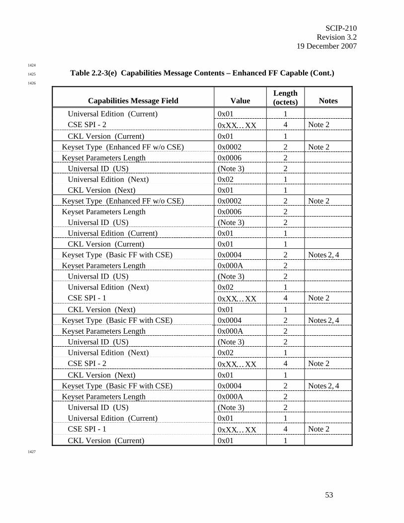
SCIP-210 Revision 3.2
19 December 2007
53
1424
Table 2.2-3(e) Capabilities Message Contents – Enhanced FF Capable (Cont.) 1425
1426
Capabilities Message Field
Value
Length (octets)
Notes
Universal Edition (Current) 0x01 1 CSE SPI - 2 0xXX…XX 4 Note 2 CKL Version (Current) 0x01 1
Keyset Type (Enhanced FF w/o CSE) 0x0002 2 Note 2 Keyset Parameters Length 0x0006 2
Universal ID (US) (Note 3) 2 Universal Edition (Next) 0x02 1 CKL Version (Next) 0x01 1
Keyset Type (Enhanced FF w/o CSE) 0x0002 2 Note 2 Keyset Parameters Length 0x0006 2
Universal ID (US) (Note 3) 2 Universal Edition (Current) 0x01 1 CKL Version (Current) 0x01 1
Keyset Type (Basic FF with CSE) 0x0004 2 Notes 2, 4 Keyset Parameters Length 0x000A 2
Universal ID (US) (Note 3) 2 Universal Edition (Next) 0x02 1 CSE SPI - 1 0xXX…XX 4 Note 2 CKL Version (Next) 0x01 1
Keyset Type (Basic FF with CSE) 0x0004 2 Notes 2, 4 Keyset Parameters Length 0x000A 2
Universal ID (US) (Note 3) 2 Universal Edition (Next) 0x02 1 CSE SPI - 2 0xXX…XX 4 Note 2 CKL Version (Next) 0x01 1
Keyset Type (Basic FF with CSE) 0x0004 2 Notes 2, 4 Keyset Parameters Length 0x000A 2
Universal ID (US) (Note 3) 2 Universal Edition (Current) 0x01 1 CSE SPI - 1 0xXX…XX 4 Note 2 CKL Version (Current) 0x01 1
1427
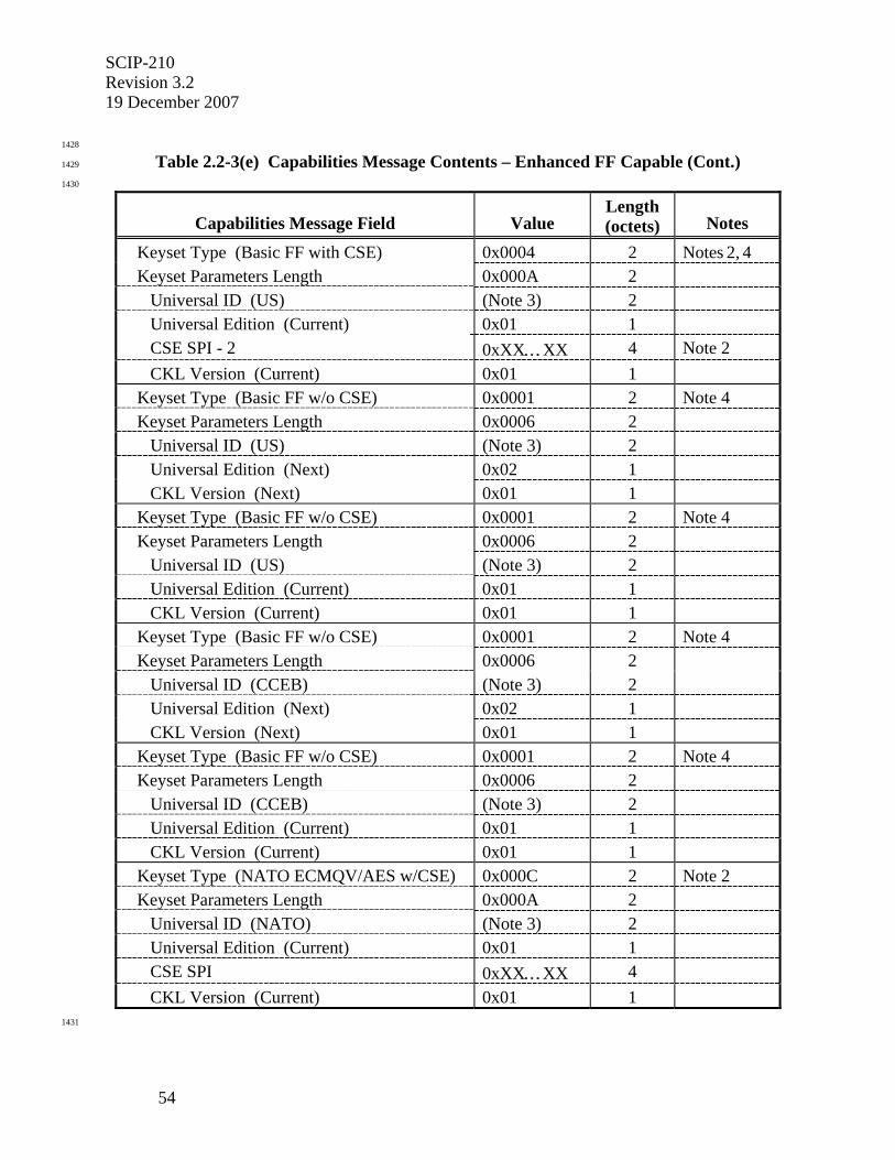
SCIP-210 Revision 3.2 19 December 2007
54
1428
Table 2.2-3(e) Capabilities Message Contents – Enhanced FF Capable (Cont.) 1429
1430
Capabilities Message Field
Value
Length (octets)
Notes
Keyset Type (Basic FF with CSE) 0x0004 2 Notes 2, 4 Keyset Parameters Length 0x000A 2
Universal ID (US) (Note 3) 2 Universal Edition (Current) 0x01 1 CSE SPI - 2 0xXX…XX 4 Note 2 CKL Version (Current) 0x01 1
Keyset Type (Basic FF w/o CSE) 0x0001 2 Note 4 Keyset Parameters Length 0x0006 2
Universal ID (US) (Note 3) 2 Universal Edition (Next) 0x02 1 CKL Version (Next) 0x01 1
Keyset Type (Basic FF w/o CSE) 0x0001 2 Note 4 Keyset Parameters Length 0x0006 2
Universal ID (US) (Note 3) 2 Universal Edition (Current) 0x01 1 CKL Version (Current) 0x01 1
Keyset Type (Basic FF w/o CSE) 0x0001 2 Note 4 Keyset Parameters Length 0x0006 2
Universal ID (CCEB) (Note 3) 2 Universal Edition (Next) 0x02 1 CKL Version (Next) 0x01 1
Keyset Type (Basic FF w/o CSE) 0x0001 2 Note 4 Keyset Parameters Length 0x0006 2
Universal ID (CCEB) (Note 3) 2 Universal Edition (Current) 0x01 1 CKL Version (Current) 0x01 1
Keyset Type (NATO ECMQV/AES w/CSE) 0x000C 2 Note 2 Keyset Parameters Length 0x000A 2
Universal ID (NATO) (Note 3) 2 Universal Edition (Current) 0x01 1 CSE SPI 0xXX…XX 4 CKL Version (Current) 0x01 1
1431
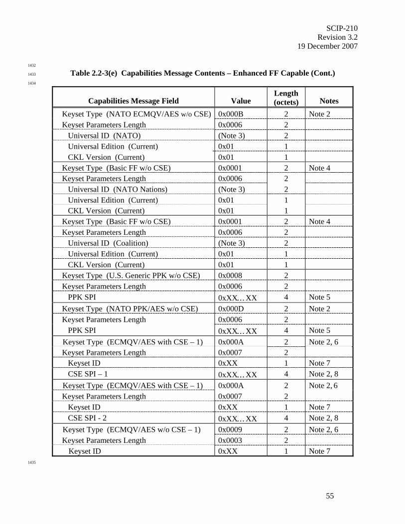
SCIP-210 Revision 3.2
19 December 2007
55
1432
Table 2.2-3(e) Capabilities Message Contents – Enhanced FF Capable (Cont.) 1433
1434
Capabilities Message Field
Value
Length (octets)
Notes
Keyset Type (NATO ECMQV/AES w/o CSE) 0x000B 2 Note 2 Keyset Parameters Length 0x0006 2
Universal ID (NATO) (Note 3) 2 Universal Edition (Current) 0x01 1 CKL Version (Current) 0x01 1
Keyset Type (Basic FF w/o CSE) 0x0001 2 Note 4 Keyset Parameters Length 0x0006 2
Universal ID (NATO Nations) (Note 3) 2 Universal Edition (Current) 0x01 1 CKL Version (Current) 0x01 1
Keyset Type (Basic FF w/o CSE) 0x0001 2 Note 4 Keyset Parameters Length 0x0006 2
Universal ID (Coalition) (Note 3) 2 Universal Edition (Current) 0x01 1 CKL Version (Current) 0x01 1
Keyset Type (U.S. Generic PPK w/o CSE) 0x0008 2 Keyset Parameters Length 0x0006 2
PPK SPI 0xXX…XX 4 Note 5 Keyset Type (NATO PPK/AES w/o CSE) 0x000D 2 Note 2 Keyset Parameters Length 0x0006 2
PPK SPI 0xXX…XX 4 Note 5 Keyset Type (ECMQV/AES with CSE – 1) 0x000A 2 Note 2, 6 Keyset Parameters Length 0x0007 2
Keyset ID 0xXX 1 Note 7 CSE SPI – 1 0xXX…XX 4 Note 2, 8
Keyset Type (ECMQV/AES with CSE – 1) 0x000A 2 Note 2, 6 Keyset Parameters Length 0x0007 2
Keyset ID 0xXX 1 Note 7 CSE SPI - 2 0xXX…XX 4 Note 2, 8
Keyset Type (ECMQV/AES w/o CSE – 1) 0x0009 2 Note 2, 6 Keyset Parameters Length 0x0003 2
Keyset ID 0xXX 1 Note 7 1435
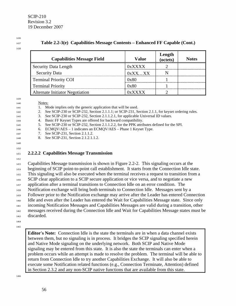
SCIP-210 Revision 3.2 19 December 2007
56
1436
Table 2.2-3(e) Capabilities Message Contents – Enhanced FF Capable (Cont.) 1437
1438
Capabilities Message Field
Value
Length (octets)
Notes
Security Data Length 0xXXXX 2 Security Data 0xXX…XX N
Terminal Priority COI 0x80 1 Terminal Priority 0x80 1 Alternate Initiator Negotiation 0xXXXX 2
1439
Notes: 1440
1. Mode implies only the generic application that will be used. 1441
2. See SCIP-230 or SCIP-232, Section 2.1.1.1; or SCIP-231, Section 2.1.1, for keyset ordering rules. 1442
3. See SCIP-230 or SCIP-232, Section 2.1.1.2.1, for applicable Universal ID values. 1443
4. Basic FF Keyset Types are offered for backward compatibility. 1444
5. See SCIP-230 or SCIP-232, Section 2.1.1.2.2, for the PPK attributes defined for the SPI. 1445
6. ECMQV/AES – 1 indicates an ECMQV/AES – Phase 1 Keyset Type. 1446
7. See SCIP-231, Section 2.1.1.2. 1447
8. See SCIP-231, Section 2.1.2.1.1.2. 1448
1449
1450
2.2.2.2 Capabilities Message Transmission 1451
1452
Capabilities Message transmission is shown in Figure 2.2-2. This signaling occurs at the 1453
beginning of SCIP point-to-point call establishment. It starts from the Connection Idle state. 1454
This signaling will also be executed when the terminal receives a request to transition from a 1455
SCIP clear application to a SCIP secure application or vice versa, and to negotiate a new 1456
application after a terminal transitions to Connection Idle on an error condition. The 1457
Notification exchange will bring both terminals to Connection Idle. Messages sent by a 1458
Follower prior to the Notification exchange may arrive after the Leader has entered Connection 1459
Idle and even after the Leader has entered the Wait for Capabilities Message state. Since only 1460
incoming Notification Messages and Capabilities Messages are valid during a transition, other 1461
messages received during the Connection Idle and Wait for Capabilities Message states must be 1462
discarded. 1463
1464
1465
Editor's Note: Connection Idle is the state the terminals are in when a data channel exists between them, but no signaling is in process. It bridges the SCIP signaling specified herein and Native Mode signaling on the underlying network. Both SCIP and Native Mode signaling may be entered from this state. It is also the state the terminals can enter when a problem occurs while an attempt is made to resolve the problem. The terminal will be able to return from Connection Idle to try another Capabilities Exchange. It will also be able to execute some Notification related functions (e.g., Connection Terminate, Attention) defined in Section 2.3.2 and any non-SCIP native functions that are available from this state.
1466
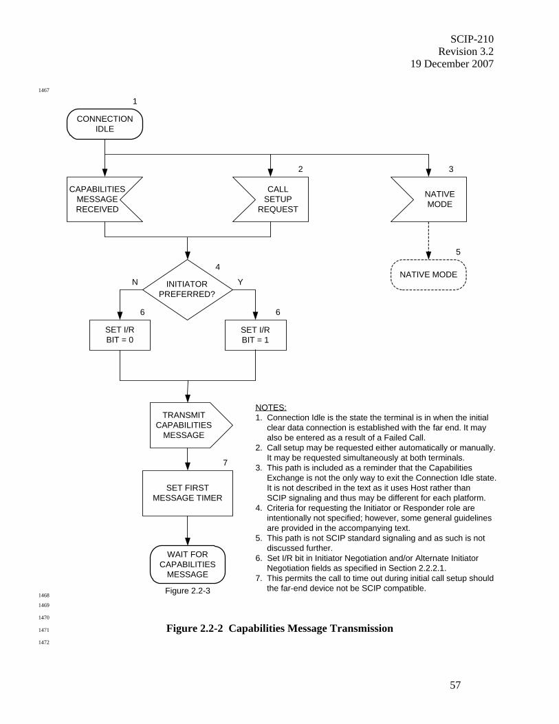
SCIP-210 Revision 3.2
19 December 2007
57
1467
1
CONNECTIONIDLE
CALLSETUP
REQUEST
NATIVEMODE
CAPABILITIESMESSAGERECEIVED
4NATIVE MODE
NOTES:1. Connection Idle is the state the terminal is in when the initial clear data connection is established with the far end. It may also be entered as a result of a Failed Call.2. Call setup may be requested either automatically or manually. It may be requested simultaneously at both terminals.3. This path is included as a reminder that the Capabilities Exchange is not the only way to exit the Connection Idle state. It is not described in the text as it uses Host rather than SCIP signaling and thus may be different for each platform.4. Criteria for requesting the Initiator or Responder role are intentionally not specified; however, some general guidelines are provided in the accompanying text.5. This path is not SCIP standard signaling and as such is not discussed further.6. Set I/R bit in Initiator Negotiation and/or Alternate Initiator Negotiation fields as specified in Section 2.2.2.1.7. This permits the call to time out during initial call setup should the far-end device not be SCIP compatible.
2 3
INITIATORPREFERRED?
N Y
5
SET FIRSTMESSAGE TIMER
WAIT FORCAPABILITIES
MESSAGE
7
Figure 2.2-3
TRANSMITCAPABILITIES
MESSAGE
SET I/RBIT = 0
SET I/RBIT = 1
6 6
1468
1469
1470
Figure 2.2-2 Capabilities Message Transmission 1471
1472

SCIP-210 Revision 3.2 19 December 2007
58
1473
A terminal will determine through some mechanism (e.g., a Capabilities Message is received, a 1474
button on the console is pressed, automatic start of SCIP call establishment when the data 1475
channel becomes available, etc.) that a point-to-point SCIP call is to be established. It shall then 1476
format a Capabilities Message as specified in Section 2.2.2.1 and transmit it to the far end. All 1477
Operational Modes and Keysets available for use during the SCIP call are offered. Vendor 1478
unique native Operational Modes may also be offered and negotiated. The Initiator/Responder 1479
(I/R) bit of the Initiator Negotiation field and/or Alternate Initiator Negotiation field (see Section 1480
2.2.2.1) is set for the role (Initiator or Responder) desired for mode negotiation. There are no 1481
specific requirements for setting Initiator and Responder roles; however, the roles should be set 1482
in such a manner as to minimize the possibility of glare, i.e., two Initiators or two Responders. 1483
Possible approaches include setting to the opposite role of that indicated in a received 1484
Capabilities Message when a Capabilities Message is received before one is transmitted, setting 1485
the calling terminal as Initiator and the called terminal as Responder, setting a terminal as 1486
Initiator when no other information is available and a local call setup request occurs prior to 1487
receiving a Capabilities Message, etc. If a glare condition exists, it will be resolved using the 1488
Random Number portion of the Initiator Negotiation field or Alternate Initiator Negotiation field 1489
of the Capabilities Message as specified in Section 2.2.2.3.1. 1490
1491
The terminal shall then set a First Message Timer, since at this point during initial call setup it 1492
may not yet know that there is a SCIP compatible terminal at the far end. After setting the First 1493
Message Timer, the terminal will then wait to receive a Capabilities Message from the far end. 1494
Processing of the received Capabilities Message is specified in Section 2.2.2.3. 1495
1496
Editor's Note: The starting and stopping of the First Message Timer may be done by a terminal that has already received a Capabilities Message just to retain commonality of code, but it is functionally superfluous to do this.
1497
1498
2.2.2.3 Capabilities Message Reception 1499
1500
The processing of the Capabilities Message consists of Unique Processing and Common 1501
Processing. Unique Processing (see 2.2.2.3.1) of a received Capabilities Message occurs when 1502
the message is initially received. Common Processing (see 2.2.2.3.2) of the received 1503
Capabilities Message occurs 1504
1505
• when the message is initially received, and 1506
• when the received Capabilities Message must be reexamined because a 1507
Parameters/Certificate Exchange determined that compatible Parameters do not exist 1508
for the negotiated Operational Mode, there is a security incompatibility, or there is an 1509
Access Control failure. 1510
1511

SCIP-210 Revision 3.2
19 December 2007
59
If either terminal transmits a Version 0 Capabilities Message, both terminals shall process 1512
Version 0 fields only. If both terminals transmit Message Version 1 or higher Capabilities 1513
Messages, the terminals shall process the entire portion of the message corresponding to the 1514
highest common version. 1515
1516
1517
2.2.2.3.1 Capabilities Message Reception Unique Processing 1518
1519
This Section discusses the processing of the Capabilities Message when it is received. 1520
1521
The Capabilities Message reception is shown in Figure 2.2-3. The processing of the timeout, 1522
that occurs if no message is received from the far end, was previously described in Section 1523
2.2.1.2. 1524
1525
If a terminal receives the far end's Capabilities Message before it has transmitted its own, it may 1526
begin processing the received Capabilities Message in parallel with generating its own so long as 1527
this does not delay transmission of its own Capabilities Message. 1528
1529
Upon receipt of a Capabilities Message, the terminal shall stop the First Message Timer, since it 1530
is now known that the far end terminal is SCIP compatible. 1531
1532
The Initiator terminal is now determined as follows. If both the transmitted and received 1533
Capabilities Messages are Version 1 or higher, the Alternate Initiator Negotiation field shall be 1534
used to determine the Initiator. If either Capabilities Message is Version 0, the Initiator 1535
Negotiation field shall be used. The Initiator Negotiation fields or Alternate Initiator 1536
Negotiation fields, treated as unsigned numbers, are compared. If the two values are equal, the 1537
terminal shall execute the Failed Call logic defined in Section 2.3.2.3.1 with the Information 1538
Code set to no initiator defined. Otherwise the Initiator and Responder roles will be adopted for 1539
Operational Mode choice in Section 2.2.2.3.2. The Initiator is the terminal that set the larger 1540
value in the field. (Note that if distinct Initiator and Responder roles were defined prior to this 1541
point, these roles are not changed. It is only when both terminals enter the Capabilities 1542
Exchange as Initiators or as Responders that this step has an impact and forces one of them to be 1543
an Initiator and one of them to be a Responder in subsequent steps.) 1544
1545
Signaling then continues as defined in Section 2.2.2.3.2. 1546
1547
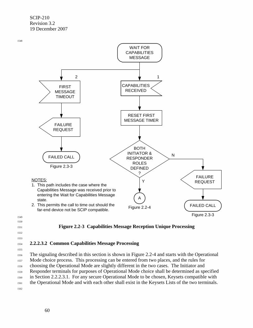
SCIP-210 Revision 3.2 19 December 2007
60
1548
1
CAPABILITIESRECEIVED
2
FAILED CALL
Figure 2.3-3
FIRSTMESSAGETIMEOUT
WAIT FORCAPABILITIES
MESSAGE
BOTHINITIATOR &RESPONDER
ROLESDEFINED
?
RESET FIRSTMESSAGE TIMER
FAILUREREQUEST
Y
N
FAILED CALL
Figure 2.3-3
FAILUREREQUEST
Figure 2.2-4
A
NOTES:1. This path includes the case where the Capabilities Message was received prior to entering the Wait for Capabilities Message state.2. This permits the call to time out should the far-end device not be SCIP compatible.
1549
1550
Figure 2.2-3 Capabilities Message Reception Unique Processing 1551
1552
1553
2.2.2.3.2 Common Capabilities Message Processing 1554
1555
The signaling described in this section is shown in Figure 2.2-4 and starts with the Operational 1556
Mode choice process. This processing can be entered from two places, and the rules for 1557
choosing the Operational Mode are slightly different in the two cases. The Initiator and 1558
Responder terminals for purposes of Operational Mode choice shall be determined as specified 1559
in Section 2.2.2.3.1. For any secure Operational Mode to be chosen, Keysets compatible with 1560
the Operational Mode and with each other shall exist in the Keysets Lists of the two terminals. 1561
1562
SCIP-210 Revision 3.2
19 December 2007
61
Case 1. The initial entry point is from Capabilities Message Reception (Section 1563
2.2.2.3.1). At this point the terminal has received and processed the far end's Capabilities 1564
Message. The terminal shall choose the first Operational Mode Entry on the Initiator's 1565
Operational Modes List which is also on the Responder's Operational Modes List. Note 1566
that if Electronic Rekey is offered by the far-end terminal (indicating it is a SCIP-LIT), 1567
this mode shall be chosen, since it is the only Operational Mode offered by the LIT. 1568
1569
Case 2. The two terminals have performed a Parameters/Certificate Exchange. At this 1570
point they discover that while they share a common Operational Mode, they do not have 1571
compatible Parameters, there is a security incompatibility, or there is an Access Control 1572
failure for that Mode (see Section 2.2.3.3). If any of these occur, the terminals shall 1573
choose the next entry on the Initiator's Operational Mode List which is also on the 1574
Responder's List. 1575
1576
If there is no common Operational Mode (Case 1) on the Initiator's list that meets the choice 1577
process as specified above (other than Native Clear Voice, which is entered via Failed Call), the 1578
terminal shall execute Failed Call processing (defined in Section 2.3.2.3.1) with an Information 1579
Code of no common operational modes. If there is no alternate common Operational Mode 1580
(Case 2) that meets the choice process, the terminal shall execute Failed Call processing with an 1581
Information Code of no matching parameters, security incompatibility, or access control failure, 1582
as is appropriate for the problem encountered with the Operational Mode chosen initially. 1583
1584
Editor's Note: It is expected that the Capabilities Exchange will be the first exchange for all SCIP terminals. However, except for choosing a common non-standard Operational Mode using this exchange, the signaling associated with non-standard Operational Modes is not addressed in this Signaling Plan. Part of the definition of a non-standard Operational Mode is the definition of the associated call setup and call control signaling. While many non-standard Operational Modes will choose to piggyback on the standard call setup and call control exchanges, this is not required. 1585
If a standard secure Operational Mode is chosen, a Keyset that is compatible with a Keyset in the 1586
other terminal shall also be chosen. If both the transmitted and received Capabilities Messages 1587
are Version 1 or higher and both terminals are in the Interoperable Terminal Priority COI, the 1588
Keyset Initiator shall be determined as follows. 1589
• If the Terminal Priority fields contain different values, the terminal with the larger 1590
Terminal Priority value shall be the Keyset Initiator. 1591
• If the Terminal Priority fields are the same, the Keyset Initiator shall be the same as the 1592
Initiator determined in Section 2.2.2.3.1. 1593
If either of the Capabilities Messages is Version 0, the Keyset Initiator shall be the same as the 1594
Initiator determined in Section 2.2.2.3.1. Finally, a terminal in the Interoperable Terminal 1595
Priority COI shall be the Keyset Initiator when it attempts to communicate with a terminal that is 1596
not in the Interoperable Terminal Priority COI. 1597
1598
1599
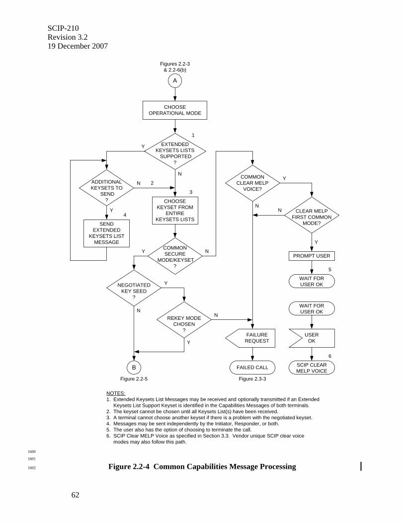
SCIP-210 Revision 3.2 19 December 2007
62
NOTES:1. Extended Keysets List Messages may be received and optionally transmitted if an Extended Keysets List Support Keyset is identified in the Capabilities Messages of both terminals.2. The keyset cannot be chosen until all Keysets List(s) have been received.3. A terminal cannot choose another keyset if there is a problem with the negotiated keyset.4. Messages may be sent independently by the Initiator, Responder, or both.5. The user also has the option of choosing to terminate the call.6. SCIP Clear MELP Voice as specified in Section 3.3. Vendor unique SCIP clear voice modes may also follow this path.
N
N
COMMONSECURE
MODE/KEYSET?
NY
CHOOSEKEYSET FROM
ENTIREKEYSETS LISTS
EXTENDEDKEYSETS LISTS
SUPPORTED?
Y
A
Figures 2.2-3& 2.2-6(b)
3
CHOOSEOPERATIONAL MODE
N
Y
REKEY MODECHOSEN
?
YNEGOTIATEDKEY SEED
?
N
B
Figure 2.2-5
FAILUREREQUEST
FAILED CALL
Figure 2.3-3
N
YCOMMONCLEAR MELP
VOICE?
N
ADDITIONALKEYSETS TO
SEND?
Y
SENDEXTENDED
KEYSETS LISTMESSAGE
WAIT FORUSER OK
USEROK
SCIP CLEARMELP VOICE
6
CLEAR MELPFIRST COMMON
MODE?
Y
PROMPT USER
WAIT FORUSER OK
5
1
4
2
1600
1601
Figure 2.2-4 Common Capabilities Message Processing 1602
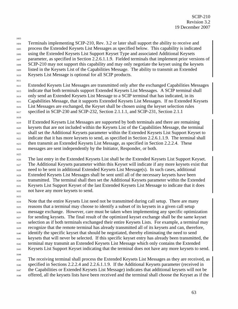
SCIP-210 Revision 3.2
19 December 2007
63
1603
Terminals implementing SCIP-210, Rev. 3.2 or later shall support the ability to receive and 1604
process the Extended Keysets List Messages as specified below. This capability is indicated 1605
using the Extended Keysets List Support Keyset Type and associated Additional Keysets 1606
parameter, as specified in Section 2.2.6.1.1.9. Fielded terminals that implement prior versions of 1607
SCIP-210 may not support this capability and may only negotiate the keyset using the keysets 1608
listed in the Keysets List of the Capabilities Message. The ability to transmit an Extended 1609
Keysets List Message is optional for all SCIP products. 1610
1611
Extended Keysets List Messages are transmitted only after the exchanged Capabilities Messages 1612
indicate that both terminals support Extended Keysets List Messages. A SCIP terminal shall 1613
only send an Extended Keysets List Message to a SCIP terminal that has indicated, in its 1614
Capabilities Message, that it supports Extended Keysets List Messages. If no Extended Keysets 1615
List Messages are exchanged, the Keyset shall be chosen using the keyset selection rules 1616
specified in SCIP-230 and SCIP-232, Section 2.1.1.1, and SCIP-231, Section 2.1.1 1617
1618
If Extended Keysets List Messages are supported by both terminals and there are remaining 1619
keysets that are not included within the Keysets List of the Capabilities Message, the terminal 1620
shall set the Additional Keysets parameter within the Extended Keysets List Support Keyset to 1621
indicate that it has more keysets to send, as specified in Section 2.2.6.1.1.9. The terminal shall 1622
then transmit an Extended Keysets List Message, as specified in Section 2.2.2.4. These 1623
messages are sent independently by the Initiator, Responder, or both. 1624
1625
The last entry in the Extended Keysets List shall be the Extended Keysets List Support Keyset. 1626
The Additional Keysets parameter within this Keyset will indicate if any more keysets exist that 1627
need to be sent in additional Extended Keysets List Message(s). In such cases, additional 1628
Extended Keysets List Messages shall be sent until all of the necessary keysets have been 1629
transmitted. The terminal shall then set the Additional Keysets parameter within the Extended 1630
Keysets List Support Keyset of the last Extended Keysets List Message to indicate that it does 1631
not have any more keysets to send. 1632
1633
Note that the entire Keysets List need not be transmitted during call setup. There are many 1634
reasons that a terminal may choose to identify a subset of its keysets in a given call setup 1635
message exchange. However, care must be taken when implementing any specific optimization 1636
for sending keysets. The final result of the optimized keyset exchange shall be the same keyset 1637
selection as if both terminals exchanged their entire Keysets Lists. For example, a terminal may 1638
recognize that the remote terminal has already transmitted all of its keysets and can, therefore, 1639
identify the specific keyset that should be negotiated, thereby eliminating the need to send 1640
keysets that will never be selected. If this specific keyset entry has already been transmitted, the 1641
terminal may transmit an Extended Keysets List Message which only contains the Extended 1642
Keysets List Support Keyset indicating that the terminal does not have any more keysets to send. 1643
1644
The receiving terminal shall process the Extended Keysets List Messages as they are received, as 1645
specified in Sections 2.2.2.4 and 2.2.6.1.1.9. If the Additional Keysets parameter (received in 1646
the Capabilities or Extended Keysets List Message) indicates that additional keysets will not be 1647
offered, all the keysets lists have been received and the terminal shall choose the Keyset as if the 1648

SCIP-210 Revision 3.2 19 December 2007
64
keysets list in the Capabilities Message, and the keysets lists from all the Extended Keysets List 1649
Messages were appended in the order received, and had been sent in the original Capabilities 1650
Message. The Extended Keysets List Support Keysets shall not be included in the appended 1651
Keysets List since these Keysets are only used to determine subsequent keyset processing and 1652
are, therefore, never negotiated. Negotiation proceeds according to the keyset selection rules 1653
specified in SCIP-230 and SCIP-232, Section 2.1.1.1; and SCIP-231, Section 2.1.1. Note that 1654
since there is no limit on the number of Extended Keysets List Messages, these Messages may be 1655
processed as they are received and then discarded as long as these keyset selection rules are 1656
followed. 1657
1658
If the terminals do not have compatible Keysets and Clear MELP Voice is not supported by both 1659
terminals, the terminal shall execute Failed Call processing with an Information Code of no 1660
compatible keysets. If there is a common secure Operational Mode, the terminals have 1661
compatible Keysets, and the negotiated Keyset is not seed key, processing continues as defined 1662
in Section 2.2.3.2. 1663
1664
If no common secure Operational Mode and/or Keyset is available but both terminals support 1665
Clear MELP Voice, the terminal shall proceed as follows. If Clear MELP Voice is the first 1666
common Operational Mode, the terminal shall prompt the user and wait for an acknowledgment 1667
before entry into the Clear MELP Voice Operational Mode. The terminal shall initiate the SCIP 1668
Clear MELP Voice application as specified in Section 3.2.1. If Clear MELP Voice is not the 1669
first common Operational Mode, the terminal shall execute Failed Call processing with an 1670
Information Code of either no common operational modes or no compatible keysets, as 1671
appropriate (i.e., Clear MELP Voice cannot be an alternate mode choice from a Capabilities 1672
exchange; it is entered via Failed Call and another Capabilities exchange – see Section 1673
2.3.2.3.1.). 1674
1675
Editor's Note: Note that as defined in Section 3.3.1.3, the Clear MELP Voice application is not actually entered until all outstanding framed messages are acknowledged. 1676
If the negotiated Keyset is seed key and the chosen Operational Mode is not Rekey, the terminal 1677
shall execute Failed Call processing with an Information Code of seed key held. If the 1678
negotiated Keyset is seed key and the chosen Operational Mode is Rekey, processing continues 1679
as defined in Section 2.2.3.2. 1680
1681
1682
2.2.2.4 Extended Keysets List Message Definition 1683
1684
If the Capabilities Message exceeds the total message length limitation specified in Section 1685
2.2.1.4, any remaining keysets that will not fit within the Keysets List of the Capabilities 1686
Message may be listed in one or more Extended Keysets List Message(s). The rules for 1687
processing the Extended Keysets List Messages are specified in Section 2.2.2.3.2. The format of 1688
the Extended Keysets List Message is shown in Table 2.2-3(f). 1689
1690
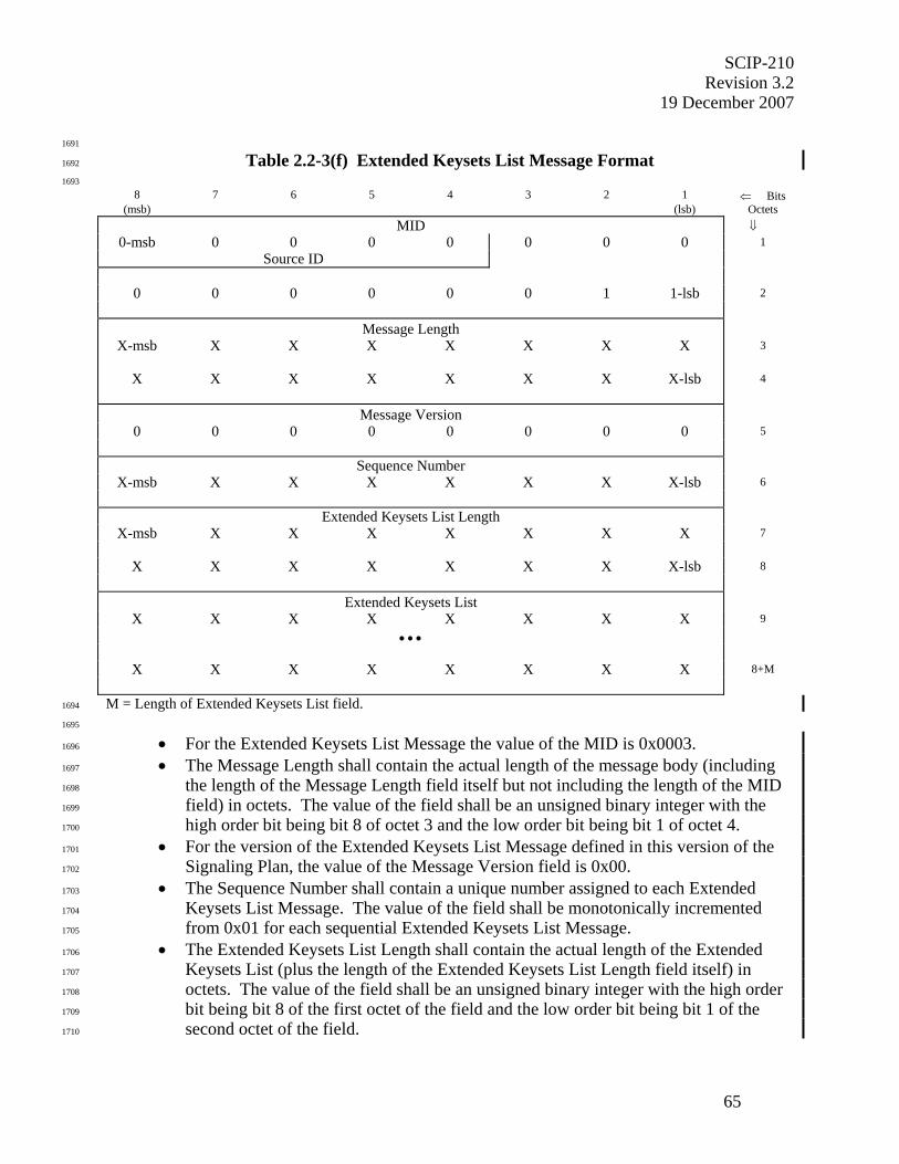
SCIP-210 Revision 3.2
19 December 2007
65
1691
Table 2.2-3(f) Extended Keysets List Message Format 1692
1693 8 7 6 5 4 3 2 1 ⇐ Bits
(msb) (lsb) Octets MID ⇓
0-msb 0 0 0 0 0 0 0 1 Source ID
0 0 0 0 0 0 1 1-lsb 2
Message Length
X-msb X X X X X X X 3
X X X X X X X X-lsb 4
Message Version
0 0 0 0 0 0 0 0 5
Sequence Number X-msb X X X X X X X-lsb 6
Extended Keysets List Length
X-msb X X X X X X X 7
X X X X X X X X-lsb 8
Extended Keysets List
X X X X X X X X 9
• • •
X X X X X X X X 8+M
M = Length of Extended Keysets List field. 1694
1695
• For the Extended Keysets List Message the value of the MID is 0x0003. 1696
• The Message Length shall contain the actual length of the message body (including 1697
the length of the Message Length field itself but not including the length of the MID 1698
field) in octets. The value of the field shall be an unsigned binary integer with the 1699
high order bit being bit 8 of octet 3 and the low order bit being bit 1 of octet 4. 1700
• For the version of the Extended Keysets List Message defined in this version of the 1701
Signaling Plan, the value of the Message Version field is 0x00. 1702
• The Sequence Number shall contain a unique number assigned to each Extended 1703
Keysets List Message. The value of the field shall be monotonically incremented 1704
from 0x01 for each sequential Extended Keysets List Message. 1705
• The Extended Keysets List Length shall contain the actual length of the Extended 1706
Keysets List (plus the length of the Extended Keysets List Length field itself) in 1707
octets. The value of the field shall be an unsigned binary integer with the high order 1708
bit being bit 8 of the first octet of the field and the low order bit being bit 1 of the 1709
second octet of the field. 1710

SCIP-210 Revision 3.2 19 December 2007
66
• The Extended Keysets List contains keysets list entries of the form given in Table 1711
2.2-3(a). Only Keysets not previously listed shall have a keysets list entry on the 1712
Extended Keysets List. Keysets list entries in the Extended Keysets List Message 1713
shall be listed as specified for the keysets list entries in the Capabilities Message. 1714
1715
1716
2.2.3 Parameters/Certificate Message 1717
1718
If a secure Operational Mode is chosen, the second step in SCIP Call Setup is the exchange of 1719
Parameters/Certificate Messages. The Credentials used by the SCIP Signaling have two parts, a 1720
Certificate and an F(R). These are exchanged in separate messages. Any parameters which must 1721
be negotiated for the chosen secure Operational Mode are also negotiated at this time. If a PPK 1722
Keyset is chosen, the Parameters/Certificate Messages are exchanged without the Certificate. If 1723
Clear MELP Voice is chosen, Credentials will not be exchanged (see also Section 2.2.6.5). 1724
1725
1726
2.2.3.1 Parameters/Certificate Message Definition 1727
1728
The format of the Parameters/Certificate Message is shown in Table 2.2-4. 1729
1730
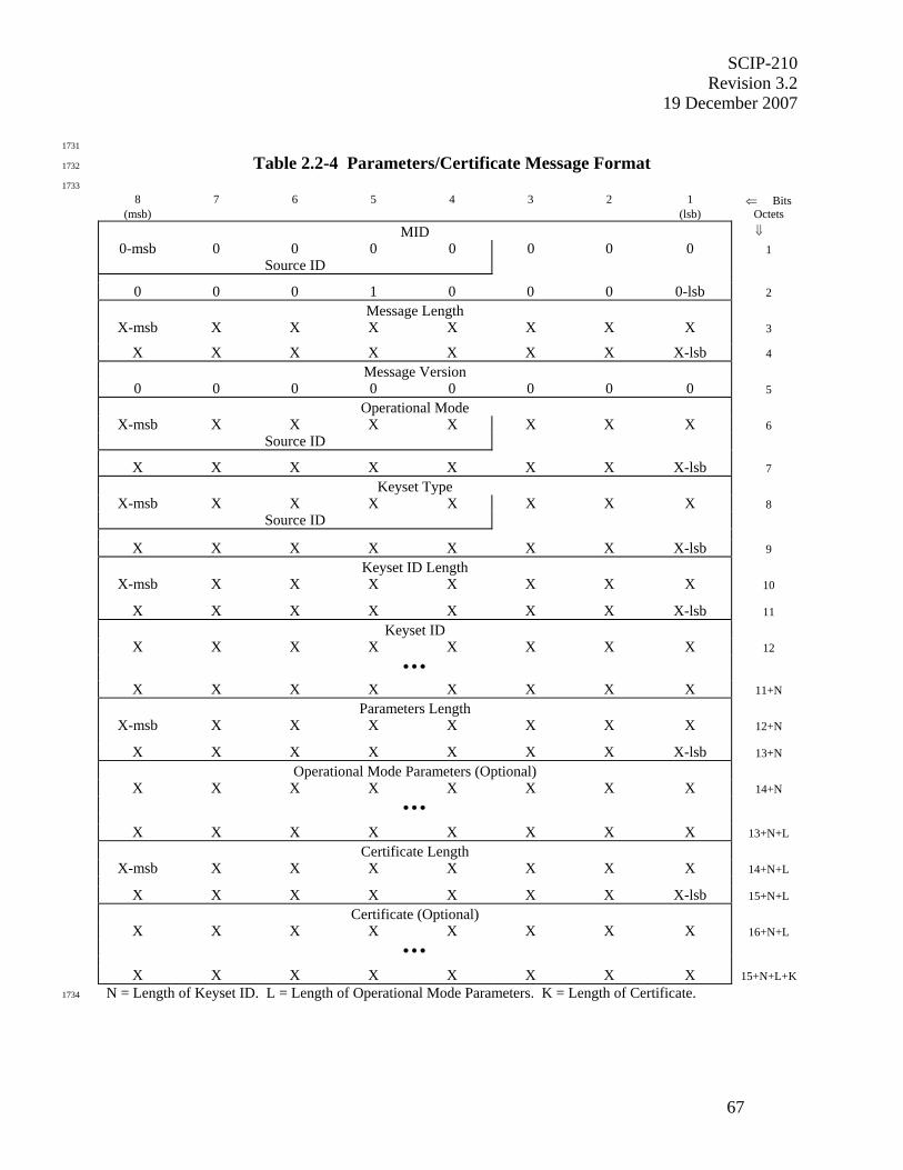
SCIP-210 Revision 3.2
19 December 2007
67
1731
Table 2.2-4 Parameters/Certificate Message Format 1732
1733
8 7 6 5 4 3 2 1 ⇐ Bits (msb) (lsb) Octets
MID ⇓ 0-msb 0 0 0 0 0 0 0 1
Source ID
0 0 0 1 0 0 0 0-lsb 2 Message Length
X-msb X X X X X X X 3
X X X X X X X X-lsb 4 Message Version
0 0 0 0 0 0 0 0 5 Operational Mode
X-msb X X X X X X X 6 Source ID
X X X X X X X X-lsb 7 Keyset Type
X-msb X X X X X X X 8 Source ID
X X X X X X X X-lsb 9 Keyset ID Length
X-msb X X X X X X X 10
X X X X X X X X-lsb 11 Keyset ID
X X X X X X X X 12 • • •
X X X X X X X X 11+N Parameters Length
X-msb X X X X X X X 12+N
X X X X X X X X-lsb 13+N Operational Mode Parameters (Optional)
X X X X X X X X 14+N • • •
X X X X X X X X 13+N+L Certificate Length
X-msb X X X X X X X 14+N+L
X X X X X X X X-lsb 15+N+L Certificate (Optional)
X X X X X X X X 16+N+L • • •
X X X X X X X X 15+N+L+K N = Length of Keyset ID. L = Length of Operational Mode Parameters. K = Length of Certificate. 1734

SCIP-210 Revision 3.2 19 December 2007
68
1735
• For the Parameters/Certificate Message the value of the MID is 0x0010. 1736
• The Message Length shall contain the actual length of the message body (including 1737
the length of the Message Length field itself but not including the length of the MID 1738
field) in octets. The value of the field shall be an unsigned binary integer with the 1739
high order bit being bit 8 of octet 3 and the low order bit being bit 1 of octet 4. 1740
• For the version of the Parameters/Certificate Message defined in this version of the 1741
Signaling Plan, the value of the Message Version field is 0x00. 1742
• The Operational Mode field shall contain the ID of the chosen Operational Mode. 1743
For the format and values of these IDs, see the definition of Operational Mode IDs in 1744
Section 2.2.2.1. The high order bit of the Operational Mode ID is placed in bit 8 of 1745
octet 6, and the low order bit of the Operational Mode ID is placed in bit 1 of octet 7. 1746
• The Keyset Type field shall identify the type of the chosen Keyset. For the format 1747
and values of these Types, see the definition of Keyset Type in Section 2.2.2.1. 1748
• The Keyset ID Length field shall contain the length, in octets, of the Keyset ID field 1749
(plus the length of the Keyset ID Length itself). The value of the field shall be an 1750
unsigned binary integer with the high order bit being bit 8 of octet 10 and the low 1751
order bit being bit 1 of octet 11. 1752
• The Keyset ID field shall contain the ID of the chosen Keyset. Keyset IDs are unique 1753
to each Keyset Type. For each standard Keyset Type, the length and format of the 1754
corresponding Keyset ID are defined in Section 2.2.6. 1755
• The Parameters Length field shall contain the length, in octets, of the Operational 1756
Mode Parameters field (plus the length of the Parameters Length itself). The value of 1757
the field shall be an unsigned binary integer with the high order bit being bit 8 of the 1758
first octet of the field and the low order bit being bit 1 of the second octet of the field. 1759
• The Operational Mode Parameters shall contain parameters for the chosen 1760
Operational Mode. The length, format and values of the Operational Mode 1761
Parameters are unique to each Operational Mode and are defined in Section 2.2.6 for 1762
each standard Operational Mode having a Parameters/Certificate Exchange. This 1763
field is optional and is not present unless Parameters are defined for a given 1764
Operational Mode. 1765
• The Certificate Length field shall contain the length, in octets, of the Certificate field 1766
(plus the length of the Certificate Length itself). The value of the field shall be an 1767
unsigned binary integer with the high order bit being bit 8 of the first octet of the field 1768
and the low order bit being bit 1 of the second octet of the field. 1769
• The Certificate field shall contain the Certificate for the chosen Keyset. The length, 1770
format and contents are unique to each key exchange type and are defined in Section 1771
2.2.6 for each key exchange type. This field is optional and is not present when a 1772
PPK Keyset is chosen. 1773
1774
SCIP-210 Revision 3.2
19 December 2007
69
1775
2.2.3.2 Parameters/Certificate Message Transmission 1776
1777
Parameters/Certificate Message transmission is shown in Figure 2.2-5. 1778
1779
If a standard secure Operational Mode was chosen via the processing defined in Section 1780
2.2.2.3.2, the following shall be performed. Both the parameters for the chosen Operational 1781
Mode and the Certificate (if applicable) of the chosen Keyset shall be transmitted in a 1782
Parameters/Certificate Message formatted as defined in Section 2.2.3.1. If the chosen Keyset is 1783
a Keyset Type with CSE and the local CSE key is not expired, the Parameters/Certificate 1784
Message shall be encrypted as specified in SCIP-230 or SCIP-231, Section 4.1.4; or SCIP-232, 1785
Section 4.4, prior to transmission. Signaling then continues as defined in Section 2.2.4.2. If a 1786
PPK Keyset is chosen, signaling continues as defined in Section 2.2.3.3. 1787
1788
The check for expired CSE key consists of comparing the Expiration Date of the local CSE key 1789
with the terminal's System Date (year/month) as specified in SCIP-230 or SCIP-232, Section 1790
2.1.1.3.1.3. If the Expiration Date of the local CSE key is earlier, the terminal shall execute 1791
Failed Call processing (see Section 2.3.2.3.1) with an Information Code of Local CSE key 1792
expired. If an ECMQV/AES - Phase 1 Keyset Type is chosen, the expired CSE key check is 1793
skipped. 1794
1795
1796
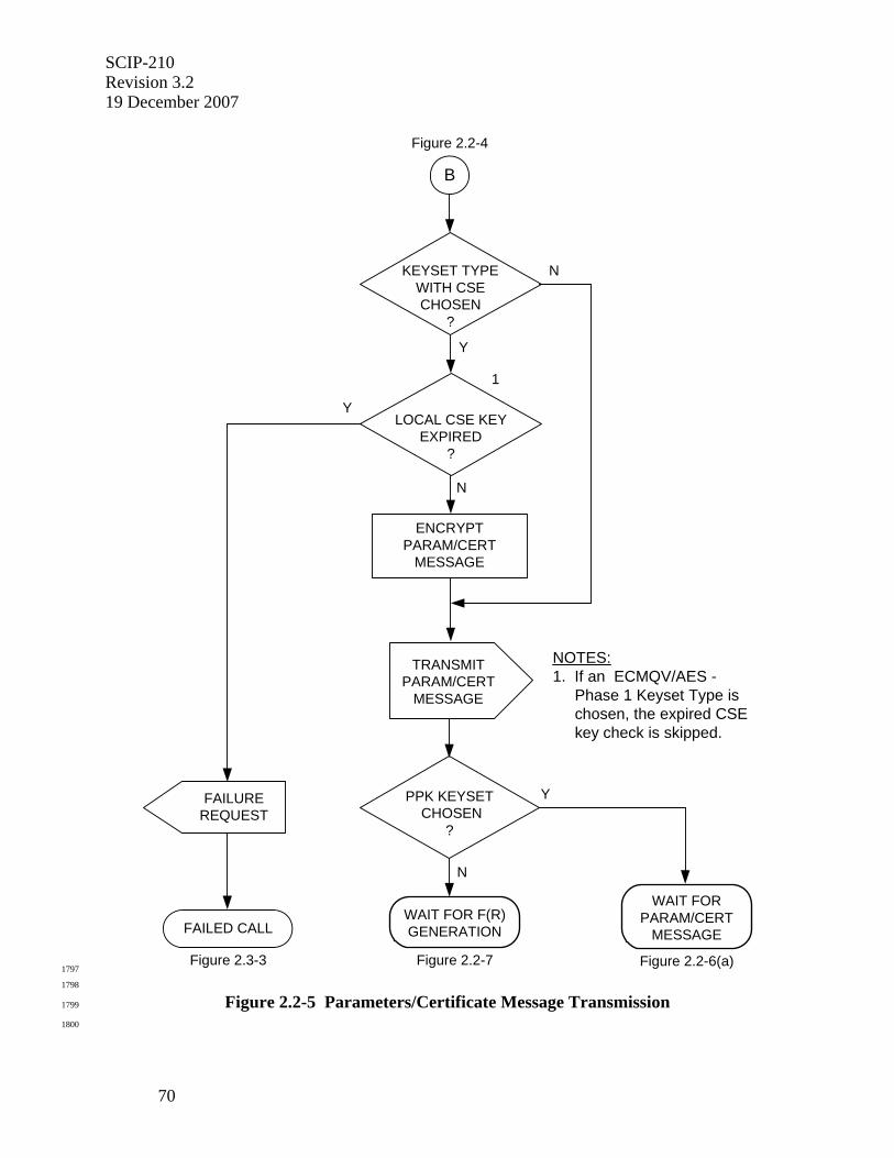
SCIP-210 Revision 3.2 19 December 2007
70
B
Figure 2.2-4
KEYSET TYPEWITH CSECHOSEN
?
N
Y
N
LOCAL CSE KEYEXPIRED
?
Y
NOTES:1. If an ECMQV/AES - Phase 1 Keyset Type is chosen, the expired CSE key check is skipped.
ENCRYPTPARAM/CERT
MESSAGE
1
TRANSMITPARAM/CERT
MESSAGE
PPK KEYSET CHOSEN
?
Y
WAIT FORPARAM/CERT
MESSAGE
Figure 2.2-6(a)
WAIT FOR F(R)GENERATION
Figure 2.2-7
N
FAILED CALL
Figure 2.3-3
FAILUREREQUEST
1797
1798
Figure 2.2-5 Parameters/Certificate Message Transmission 1799
1800
SCIP-210 Revision 3.2
19 December 2007
71
1801
2.2.3.3 Parameters/Certificate Message Reception 1802
1803
Parameters/Certificate Message reception is shown in Figure 2.2-6(a), Figure 2.2-6(b), and 1804
Figure 2.2-6(c). 1805
1806
The terminal may begin processing the far end's Parameters/Certificate Message, for the chosen 1807
Operational Mode and Keyset, when it is received. If a terminal receives the far end's 1808
Parameters/Certificate Message before it has transmitted its own Parameters/Certificate 1809
Message, it may begin processing the received Parameters/Certificate Message in parallel with 1810
generating its own Parameters/Certificate Message so long as this does not delay the 1811
transmission of its own message. 1812
1813
If the chosen Keyset is a Keyset Type with CSE, the received Parameters/Certificate Message is 1814
encrypted. Prior to processing, it shall be decrypted as specified in SCIP-230 or SCIP-231, 1815
Section 4.1.4; or SCIP-232, Section 4.4. 1816
1817
1818
1819
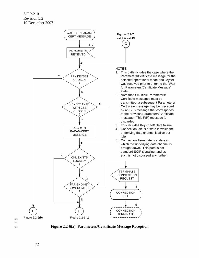
SCIP-210 Revision 3.2 19 December 2007
72
WAIT FOR PARAM/CERT MESSAGE
Figures 2.2-7,2.2-8 & 2.2-10
C1, 2
PARAM/CERTRECEIVED
PPK KEYSETCHOSEN
?
N
Y
Y
CKL EXISTSLOCALLY
?
N
FAR-END KEYCOMPROMISED
?
N
3
Y
KEYSET TYPEWITH CSECHOSEN
?
N
Y
DECRYPTPARAM/CERT
MESSAGE
TERMINATECONNECTION
REQUEST
4
CONNECTIONIDLE
CONNECTIONTERMINATE
5
Figure 2.2-6(b)
E
Figure 2.2-6(b)
D
NOTES:1. This path includes the case where the Parameters/Certificate message for the selected operational mode and keyset was received prior to entering the 'Wait for Parameters/Certificate Message' state.2. Note that if multiple Parameters/ Certificate messages must be transmitted, a subsequent Parameters/ Certificate message may be preceded by an F(R) message that corresponds to the previous Parameters/Certificate message. This F(R) message is discarded.3. This includes Key Cutoff Date failure.4. Connection Idle is a state in which the underlying data channel is alive but idle.5. Connection Terminate is a state in which the underlying data channel is brought down. This path is not standard SCIP signaling, and as such is not discussed any further.
1820
1821
Figure 2.2-6(a) Parameters/Certificate Message Reception 1822
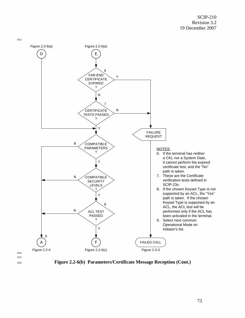
SCIP-210 Revision 3.2
19 December 2007
73
1823
Figure 2.2-4
9
A
NOTES:6. If the terminal has neither a CKL nor a System Date, it cannot perform the expired certificate test, and the "No" path is taken.7. These are the Certificate verification tests defined in
SCIP-23x.8. If the chosen Keyset Type is not supported by an ACL, the “Yes” path is taken. If the chosen Keyset Type is supported by an ACL, the ACL test will be performed only if the ACL has been activated in the terminal.9. Select next common Operational Mode on Initiator's list.
Figure 2.2-6(a)
E
Y
COMPATIBLEPARAMETERS
?
N
Y
COMPATIBLESECURITY
LEVELS?
N
CERTIFICATETESTS PASSED
?
N
7
Y
FAR-ENDCERTIFICATE
EXPIRED?
Y
N
6
FAILED CALL
Figure 2.3-3
ACL TESTPASSED
?
Y
N
8
Figure 2.2-6(c)
F
Figure 2.2-6(a)
D
FAILUREREQUEST
1824
1825
Figure 2.2-6(b) Parameters/Certificate Message Reception (Cont.) 1826
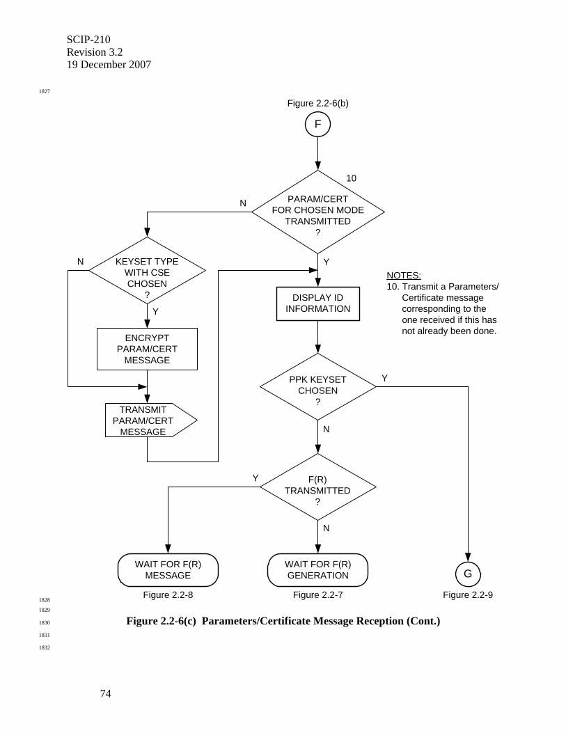
SCIP-210 Revision 3.2 19 December 2007
74
1827
F
Figure 2.2-6(b)
N
10
Y
PARAM/CERTFOR CHOSEN MODE
TRANSMITTED?
DISPLAY IDINFORMATION
PPK KEYSETCHOSEN
?
N
Y
F(R)TRANSMITTED
?
Y
N
WAIT FOR F(R)GENERATION
Figure 2.2-7
WAIT FOR F(R)MESSAGE
Figure 2.2-8
TRANSMITPARAM/CERT
MESSAGE
KEYSET TYPEWITH CSECHOSEN
?
N
Y
ENCRYPTPARAM/CERT
MESSAGE
Figure 2.2-9
G
NOTES:10. Transmit a Parameters/ Certificate message corresponding to the one received if this has not already been done.
1828
1829
Figure 2.2-6(c) Parameters/Certificate Message Reception (Cont.) 1830
1831
1832
SCIP-210 Revision 3.2
19 December 2007
75
1833
The following applies to FIREFLY (defined in SCIP-230) and NATO ECMQV (defined in 1834
SCIP-232) Certificates only. 1835
1836
If the terminal does not have a local CKL for the chosen Universal Edition, the 1837
compromised key check below is skipped. If the terminal has no System Date (see SCIP-1838
230, Section 2.1.2.3.2, or SCIP-232, Section 2.1.2.3.1), the expired key check below is 1839
also skipped. 1840
1841
The test for compromised key consists of checking for the received Certificate's KMID 1842
on the CKL and also comparing the Expiration Date in the Certificate with the Key 1843
Cutoff Date in the CKL (see SCIP-230 or SCIP-232, Sections 2.1.2.2.1 and 2.1.2.2.2). If 1844
the received Certificate's KMID is on the local CKL for that Universal Edition, or if the 1845
Expiration Date in the Certificate is earlier than the Key Cutoff Date in the CKL, the 1846
terminal shall terminate the connection immediately and without providing the far end 1847
terminal with any indication (i.e., without sending a Notification Message). 1848
1849
Editor's Note: A compromised Certificate is no longer carried on a CKL when its expiration date is earlier than the CKL's Key Cutoff Date. The CKL design assumes that such an expired key will not be communicated with.
1850
The check for expired key consists of comparing the Expiration Date in the Certificate 1851
with the terminal's System Date (year/month) as specified in SCIP-230 or SCIP-232, 1852
Section 2.1.2.2.3. If the Expiration Date in the Certificate is earlier, the terminal shall 1853
execute Failed Call processing (see Section 2.3.2.3.1) with an Information Code of 1854
Certificate expired. 1855
1856
The Certificate verification tests specified in SCIP-230, Sections 2.1.1.4.2 and 2.1.1.4.3, 1857
or SCIP-232, Appendix F, are now performed. For Electronic Rekey, an additional test is 1858
performed to verify that the far-end terminal is a SCIP-LIT (See SCIP-230, Section 6.1, 1859
or SCIP-232, Appendix E.1). If the received Certificate fails any of these tests, the 1860
terminal shall execute Failed Call processing with an Information Code of Certificate 1861
verification failure. 1862
1863
The following applies only to the Phase 1 X.509 Certificate as defined in SCIP-231. 1864
1865
The Certificate verification tests specified in SCIP-231, Sections 2.1.3.3.2 and 2.1.3.3.4, 1866
are now performed. If the received Certificate fails any of these tests, the terminal shall 1867
execute Failed Call processing with an Information Code of Certificate verification 1868
failure. 1869
1870
1871
SCIP-210 Revision 3.2 19 December 2007
76
The Operational Mode Parameters are now checked. For standard secure modes, the Operational 1872
Mode Parameters contain an Options List. (See Section 2.2.6.2 for Secure Voice Options, 1873
Section 2.2.6.3 for Secure Data Options, and Section 2.2.6.4 for Secure Electronic Rekey 1874
Options.) The Options List Entries will be examined in the order in which they appear. The first 1875
entry on the Initiator's Options List that is supported by the Responder shall be chosen. 1876
1877
If no entry on the Initiator's Options List is supported by the Responder, the Operational Mode is 1878
noted as one that has no compatible parameters and is not to be chosen. Processing then 1879
continues as specified in Section 2.2.2.3.2 (Case 2), where the terminals will attempt to choose 1880
another Operational Mode. 1881
1882
For Secure Data or Secure Voice if there is no overlap among the local and far-end Security 1883
Level settings and key classifications for the chosen Operational Mode and Keyset (see SCIP-1884
230 or SCIP-232, Section 2.1.3.2), the Operational Mode is noted as one that has a security 1885
incompatibility and is not to be chosen. Processing again continues as specified in Section 1886
2.2.2.3.2 (Case 2) where the terminals will attempt to choose another Operational Mode. 1887
1888
If the Access Control List (ACL) has been activated for the chosen Operational Mode and the 1889
chosen Keyset Type is supported by an ACL, the terminal performs the ACL test as specified in 1890
SCIP-230 or SCIP-232, Section 2.1.3.1.1. If the ACL test fails, the Operational Mode is noted 1891
as one for which access is denied and is not to be chosen. Processing then continues as specified 1892
in Section 2.2.2.3.2 (Case 2) where the terminals will attempt to choose another Operational 1893
Mode. If the ACL has not been activated for the chosen Operational Mode and/or the chosen 1894
Keyset Type is not supported by an ACL, the ACL check is skipped. 1895
1896
If all the above tests pass, the terminal shall verify that the received Parameters/Certificate 1897
Message just processed corresponds to (i.e., contains the same Operational Mode as) the last 1898
Parameters/Certificate Message it transmitted. If it does not, the terminal shall transmit a 1899
Parameters/Certificate Message corresponding to the one just processed. If the chosen Keyset is 1900
a Keyset Type with CSE, the Parameters/Certificate Message shall be encrypted as specified in 1901
SCIP-230 or SCIP-231, Section 4.1.4; or SCIP-232, Section 4.4, prior to transmission. The 1902
authentication information is displayed to the user, as defined for each specific Keyset Type in 1903
SCIP-230, Sections 2.1.1.4.2.3 and 2.1.1.8.1, SCIP-231, Section 2.1.3.4, or SCIP-232, Sections 1904
2.1.1.4.1.4 and 2.1.1.8.1. If a PPK Keyset is chosen, processing proceeds as defined in Section 1905
2.2.5.2 (no F(R) message is transmitted). Otherwise, processing proceeds as defined in Section 1906
2.2.4.2 (if the F(R) has not yet been transmitted) or Section 2.2.4.3 (if the F(R) has already been 1907
transmitted). 1908
1909
1910
2.2.4 F(R) Message 1911
1912
1913
2.2.4.1 F(R) Message Definition 1914
1915
The format of the F(R) Message is shown in Table 2.2-5. 1916
1917
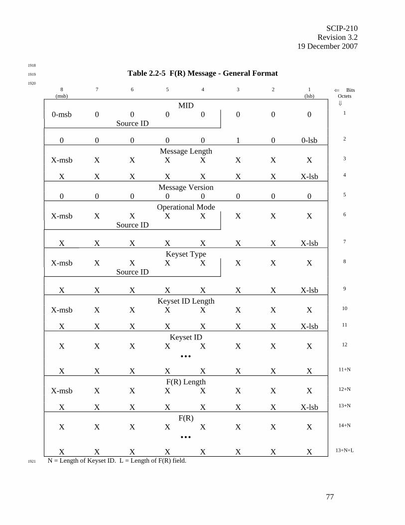
SCIP-210 Revision 3.2
19 December 2007
77
1918
Table 2.2-5 F(R) Message - General Format 1919
1920
8 7 6 5 4 3 2 1 ⇐ Bits (msb) (lsb) Octets
MID ⇓
0-msb 0 0 0 0 0 0 0 1
Source ID
0 0 0 0 0 1 0 0-lsb 2
Message Length
X-msb X X X X X X X 3
X X X X X X X X-lsb 4
Message Version
0 0 0 0 0 0 0 0 5
Operational Mode
X-msb X X X X X X X 6
Source ID
X X X X X X X X-lsb 7
Keyset Type
X-msb X X X X X X X 8
Source ID
X X X X X X X X-lsb 9
Keyset ID Length
X-msb X X X X X X X 10
X X X X X X X X-lsb 11
Keyset ID
X X X X X X X X 12
• • •
X X X X X X X X 11+N
F(R) Length
X-msb X X X X X X X 12+N
X X X X X X X X-lsb 13+N
F(R)
X X X X X X X X 14+N
• • •
X X X X X X X X 13+N+L
N = Length of Keyset ID. L = Length of F(R) field. 1921

SCIP-210 Revision 3.2 19 December 2007
78
1922
• For the F(R) Message the value of the MID is 0x0004. 1923
• The Message Length shall contain the actual length of the message body (including 1924
the length of the Message Length field itself but not including the length of the MID 1925
field) in octets. The value of the field shall be an unsigned binary integer with the 1926
high order bit being bit 8 of octet 3 and the low order bit being bit 1 of octet 4. 1927
• For the version of the F(R) Message defined in this version of the Signaling Plan, the 1928
value of the Message Version field is 0x00. 1929
• The Operational Mode field shall contain the ID of the chosen Operational Mode. 1930
For the format and values of these IDs, see the definition of Operational Mode IDs in 1931
Section 2.2.2.1. The high order bit of the Operational Mode ID is placed in bit 8 of 1932
octet 6 and the low order bit of the Operational Mode ID is placed in bit 1 of octet 7. 1933
• The Keyset Type field shall identify the type of the chosen Keyset. For the format 1934
and values of these Types, see the definition of Keyset Type in Section 2.2.2.1. 1935
• The Keyset ID Length shall contain the actual length of the Keyset ID field (plus the 1936
length of the Keyset ID Length field itself) in octets. The value of the field shall be 1937
an unsigned binary integer with the high order bit being bit 8 of octet 10 and the low 1938
order bit being bit 1 of octet 11. 1939
• The Keyset ID field shall contain the ID of the chosen Keyset. Keyset IDs are unique 1940
to each Keyset Type. For each standard Keyset Type, the length and format of the 1941
corresponding Keyset ID are defined in Section 2.2.6.1. 1942
• The F(R) Length shall contain the actual length of the F(R) field (including the length 1943
of the F(R) Length field itself) in octets. The value of the field shall be an unsigned 1944
binary integer with the high order bit being bit 8 of the first octet of the field and the 1945
low order bit being bit 1 of the second octet of the field. 1946
• The F(R) field shall contain an F(R) corresponding to the chosen Keyset. The length, 1947
format and contents are unique to each key exchange type and are defined in Section 1948
2.2.6.1 for each key exchange type. 1949
1950
1951
2.2.4.2 F(R) Message Transmission 1952
1953
F(R) Message transmission is shown in Figure 2.2-7. At this point the Parameters/Certificate 1954
Message has been formatted and transmitted. If the far-end Parameters/Certificate Message 1955
arrives before the F(R) has been generated, the incoming Parameters/Certificate Message is first 1956
processed as described in Section 2.2.3.3. 1957
1958
If F(R) is not already available, F(R) generation proceeds to completion. An F(R) Message 1959
containing the F(R) for the chosen Keyset, and formatted as defined in Section 2.2.4.1, shall be 1960
transmitted to the far end. If the incoming Parameters/Certificate Message has already been 1961
processed, the terminal proceeds as defined in Section 2.2.4.3. Else the terminal waits until it 1962
receives the Parameters/Certificate Message from the far end, at which point it proceeds as 1963
defined in Section 2.2.3.3. 1964
1965
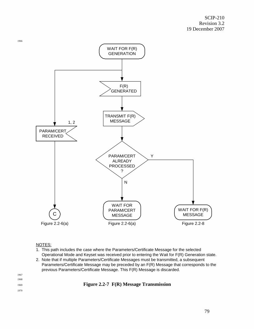
SCIP-210 Revision 3.2
19 December 2007
79
1966
TRANSMIT F(R)MESSAGE
F(R)GENERATED
PARAM/CERTALREADY
PROCESSED?
Y
N
WAIT FORPARAM/CERT
MESSAGE
Figure 2.2-6(a)
NOTES:1. This path includes the case where the Parameters/Certificate Message for the selected Operational Mode and Keyset was received prior to entering the Wait for F(R) Generation state.2. Note that if multiple Parameters/Certificate Messages must be transmitted, a subsequent Parameters/Certificate Message may be preceded by an F(R) Message that corresponds to the previous Parameters/Certificate Message. This F(R) Message is discarded.
WAIT FOR F(R)GENERATION
WAIT FOR F(R)MESSAGE
Figure 2.2-8
C
Figure 2.2-6(a)
PARAM/CERTRECEIVED
1, 2
1967
1968
Figure 2.2-7 F(R) Message Transmission 1969
1970
SCIP-210 Revision 3.2 19 December 2007
80
1971
2.2.4.3 F(R) Message Reception 1972
1973
F(R) Message reception is shown in Figure 2.2-8. At this point the terminal has processed the 1974
received Parameters/Certificate Message for the chosen Operational Mode and has determined 1975
that the Operational Mode and its parameters, and the Certificate, are acceptable. 1976
1977
The terminal may begin processing the far end's F(R), for the chosen Operational Mode and 1978
Keyset, when it is received. This is discussed in Section 2.2.4.3.1. If a terminal receives the far 1979
end's F(R) before it has transmitted its own, it may begin processing the received F(R) in parallel 1980
with generating its own so long as this does not delay transmission of its own F(R). Note that 1981
multiple F(R) Messages may have been sent, but only one of them should have the chosen 1982
Operational Mode and Keyset. 1983
1984
Under exceptional conditions the terminal may receive another Parameters/Certificate Message 1985
at this point. Processing in this exception case is described in Section 2.2.4.3.2. 1986
1987
1988
2.2.4.3.1 F(R) Message Received 1989
1990
Upon receipt of the F(R), the F(R) verification tests specified in SCIP-230, Section 2.1.1.4.3, 1991
SCIP-231, Section 2.1.5, or SCIP-232, Appendix F.3 are now performed. If the received F(R) 1992
fails any of these tests, the terminal shall execute Failed Call processing. If the tests pass, key 1993
generation is initiated, and signaling continues as defined in Section 2.2.5. The generation of the 1994
traffic key from the Certificate and the F(R) is defined in SCIP-230 or SCIP-232, Section 1995
2.1.1.7; or SCIP-231, Section 2.1.6. 1996
1997
1998
2.2.4.3.2 Parameters/Certificate Message Received 1999
2000
If a Parameters/Certificate Message is received, this indicates that the far end has determined 2001
that there are no compatible parameters, there is a security incompatibility, or there is an Access 2002
Control failure for the previously chosen Operational Mode, and is attempting to proceed using 2003
an alternate Operational Mode. In this case, the incoming Parameters/Certificate Message is 2004
processed as specified in Section 2.2.3.3. 2005
2006
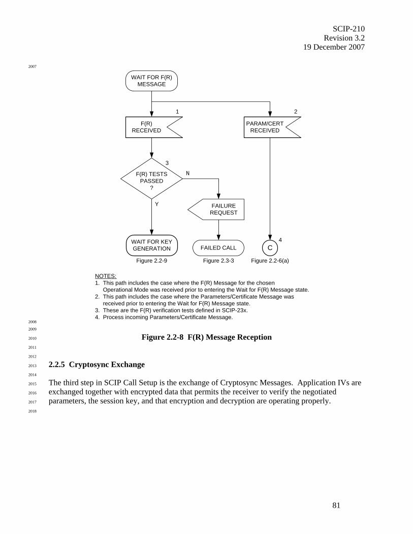
SCIP-210 Revision 3.2
19 December 2007
81
2007
WAIT FOR F(R)MESSAGE
1
F(R)RECEIVED
F(R) TESTSPASSED
?
N
3
Y
NOTES:1. This path includes the case where the F(R) Message for the chosen Operational Mode was received prior to entering the Wait for F(R) Message state.2. This path includes the case where the Parameters/Certificate Message was received prior to entering the Wait for F(R) Message state.3. These are the F(R) verification tests defined in SCIP-23x.4. Process incoming Parameters/Certificate Message.
WAIT FOR KEYGENERATION
Figure 2.2-9
FAILUREREQUEST
Figure 2.3-3
FAILED CALL
PARAM/CERTRECEIVED
2
C
Figure 2.2-6(a)
4
2008
2009
Figure 2.2-8 F(R) Message Reception 2010
2011
2012
2.2.5 Cryptosync Exchange 2013
2014
The third step in SCIP Call Setup is the exchange of Cryptosync Messages. Application IVs are 2015
exchanged together with encrypted data that permits the receiver to verify the negotiated 2016
parameters, the session key, and that encryption and decryption are operating properly. 2017
2018
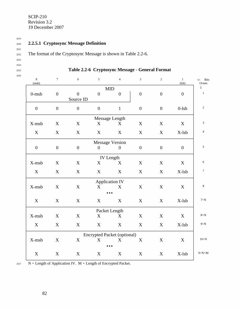
SCIP-210 Revision 3.2 19 December 2007
82
2019
2.2.5.1 Cryptosync Message Definition 2020
2021
The format of the Cryptosync Message is shown in Table 2.2-6. 2022
2023
2024
Table 2.2-6 Cryptosync Message - General Format 2025
2026
8 7 6 5 4 3 2 1 ⇐ Bits (msb) (lsb) Octets
MID ⇓
0-msb 0 0 0 0 0 0 0 1
Source ID
0 0 0 0 1 0 0 0-lsb 2
Message Length
X-msb X X X X X X X 3
X X X X X X X X-lsb 4
Message Version
0 0 0 0 0 0 0 0 5
IV Length
X-msb X X X X X X X 6
X X X X X X X X-lsb 7
Application IV
X-msb X X X X X X X 8
• • •
X X X X X X X X-lsb 7+N
Packet Length
X-msb X X X X X X X 8+N
X X X X X X X X-lsb 9+N
Encrypted Packet (optional)
X-msb X X X X X X X 10+N
• • •
X X X X X X X X-lsb 9+N+M
N = Length of Application IV. M = Length of Encrypted Packet. 2027
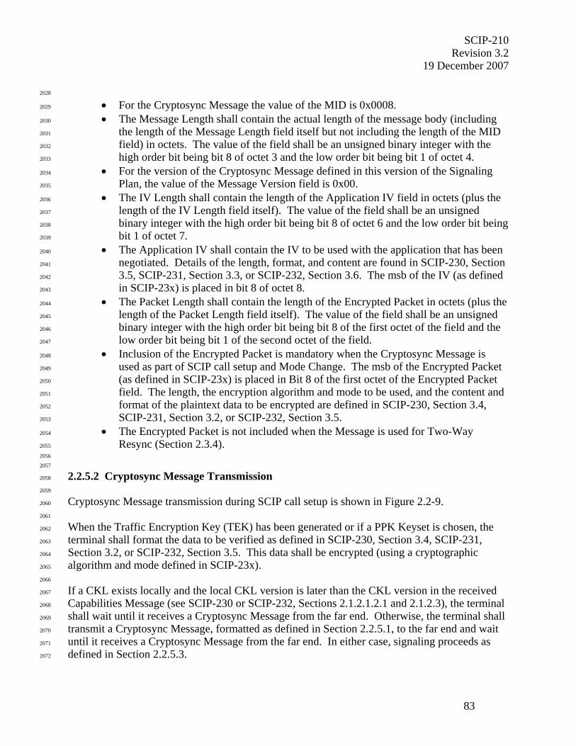
SCIP-210 Revision 3.2
19 December 2007
83
2028
• For the Cryptosync Message the value of the MID is 0x0008. 2029
• The Message Length shall contain the actual length of the message body (including 2030
the length of the Message Length field itself but not including the length of the MID 2031
field) in octets. The value of the field shall be an unsigned binary integer with the 2032
high order bit being bit 8 of octet 3 and the low order bit being bit 1 of octet 4. 2033
• For the version of the Cryptosync Message defined in this version of the Signaling 2034
Plan, the value of the Message Version field is 0x00. 2035
• The IV Length shall contain the length of the Application IV field in octets (plus the 2036
length of the IV Length field itself). The value of the field shall be an unsigned 2037
binary integer with the high order bit being bit 8 of octet 6 and the low order bit being 2038
bit 1 of octet 7. 2039
• The Application IV shall contain the IV to be used with the application that has been 2040
negotiated. Details of the length, format, and content are found in SCIP-230, Section 2041
3.5, SCIP-231, Section 3.3, or SCIP-232, Section 3.6. The msb of the IV (as defined 2042
in SCIP-23x) is placed in bit 8 of octet 8. 2043
• The Packet Length shall contain the length of the Encrypted Packet in octets (plus the 2044
length of the Packet Length field itself). The value of the field shall be an unsigned 2045
binary integer with the high order bit being bit 8 of the first octet of the field and the 2046
low order bit being bit 1 of the second octet of the field. 2047
• Inclusion of the Encrypted Packet is mandatory when the Cryptosync Message is 2048
used as part of SCIP call setup and Mode Change. The msb of the Encrypted Packet 2049
(as defined in SCIP-23x) is placed in Bit 8 of the first octet of the Encrypted Packet 2050
field. The length, the encryption algorithm and mode to be used, and the content and 2051
format of the plaintext data to be encrypted are defined in SCIP-230, Section 3.4, 2052
SCIP-231, Section 3.2, or SCIP-232, Section 3.5. 2053
• The Encrypted Packet is not included when the Message is used for Two-Way 2054
Resync (Section 2.3.4). 2055
2056
2057
2.2.5.2 Cryptosync Message Transmission 2058
2059
Cryptosync Message transmission during SCIP call setup is shown in Figure 2.2-9. 2060
2061
When the Traffic Encryption Key (TEK) has been generated or if a PPK Keyset is chosen, the 2062
terminal shall format the data to be verified as defined in SCIP-230, Section 3.4, SCIP-231, 2063
Section 3.2, or SCIP-232, Section 3.5. This data shall be encrypted (using a cryptographic 2064
algorithm and mode defined in SCIP-23x). 2065
2066
If a CKL exists locally and the local CKL version is later than the CKL version in the received 2067
Capabilities Message (see SCIP-230 or SCIP-232, Sections 2.1.2.1.2.1 and 2.1.2.3), the terminal 2068
shall wait until it receives a Cryptosync Message from the far end. Otherwise, the terminal shall 2069
transmit a Cryptosync Message, formatted as defined in Section 2.2.5.1, to the far end and wait 2070
until it receives a Cryptosync Message from the far end. In either case, signaling proceeds as 2071
defined in Section 2.2.5.3. 2072
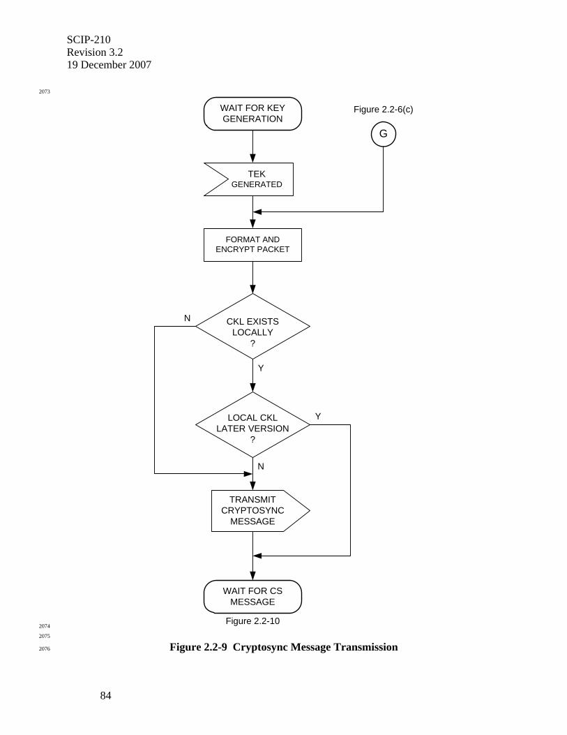
SCIP-210 Revision 3.2 19 December 2007
84
2073
WAIT FOR KEYGENERATION
TEKGENERATED
FORMAT ANDENCRYPT PACKET
Y
N
TRANSMITCRYPTOSYNC
MESSAGE
WAIT FOR CSMESSAGE
Figure 2.2-10
LOCAL CKLLATER VERSION
?
CKL EXISTSLOCALLY
?
Y
N
Figure 2.2-6(c)
G
2074
2075
Figure 2.2-9 Cryptosync Message Transmission 2076
SCIP-210 Revision 3.2
19 December 2007
85
2077
2.2.5.3 Cryptosync Message Reception 2078
2079
Cryptosync Message reception during SCIP call setup is shown in Figure 2.2-10. 2080
2081
The terminal will process the far end's Cryptosync Message when it is received. This is 2082
discussed in Section 2.2.5.3.1. If a terminal receives the far end's Cryptosync Message before it 2083
has transmitted its own, it may begin processing the received Cryptosync Message in parallel 2084
with generating its own. 2085
2086
Under exceptional conditions the terminal may receive another Parameters/Certificate Message 2087
at this point. Processing in this exception case is described in Section 2.2.5.3.2. 2088
2089
2090
2.2.5.3.1 Cryptosync Message Received 2091
2092
If a CKL exists locally and the local CKL version is later than the CKL version in the received 2093
Capabilities Message, one or more CKL Transfers shall be performed, as specified in Section 2094
2.3.2.4, to transmit the local CKL to the far end. The terminal shall then transmit a Cryptosync 2095
Message, formatted as defined in Section 2.2.5.1, to the far end. Once transmission of the 2096
Cryptosync Message is complete, processing continues as follows. 2097
2098
The terminal shall verify the Encrypted Packet contained in the Cryptosync Message as specified 2099
in SCIP-230, Section 3.4.1, SCIP-231, Section 3.2.1, or SCIP-232, Section 3.5.1. If this check is 2100
not passed, the terminal shall execute Failed Call processing, defined in Section 2.3.2.3.1, with 2101
an Information Code of sync message verification failure. 2102
2103
For standard secure Operational Modes, the terminal shall then initiate the chosen application, 2104
using the exchanged Application IVs, as specified in Section 3.2. 2105
2106
Editor's Note: Note that as defined in Section 3.2, the application is not actually entered until all outstanding framed messages are acknowledged. In particular, the application is not entered until all frames of the Cryptosync Message have been acknowledged. 2107
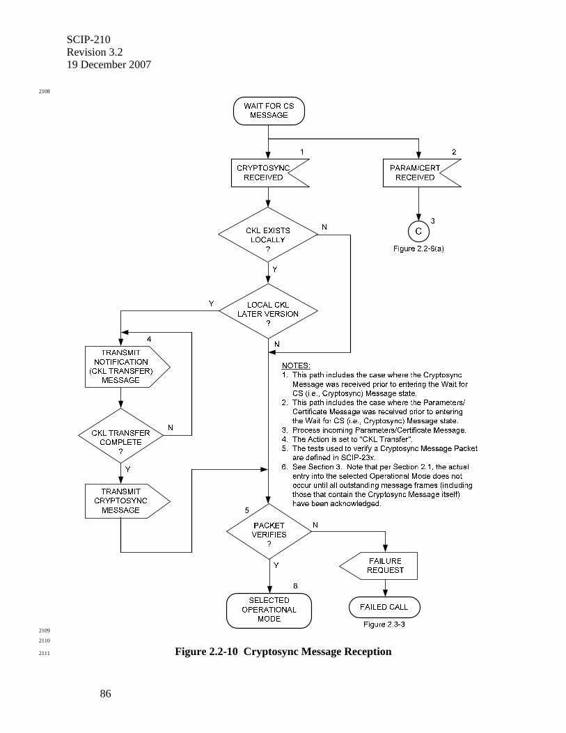
SCIP-210 Revision 3.2 19 December 2007
86
2108
2109
2110
Figure 2.2-10 Cryptosync Message Reception 2111
SCIP-210 Revision 3.2
19 December 2007
87
2112
2.2.5.3.2 Parameters/Certificate Message Received 2113
2114
If a Parameters/Certificate Message is received, this indicates that the far end has determined 2115
that there are no compatible parameters, there is a security incompatibility, or there is an Access 2116
Control failure for the previously chosen Operational Mode, and is attempting to proceed using 2117
an alternate Operational Mode. In this case, the incoming Parameters/Certificate Message is 2118
processed as specified in Section 2.2.3.3. 2119
2120
2121
2.2.6 Operational Mode and Keyset Type Specific Instantiations 2122
2123
This section defines the Operational Mode and Keyset Type specific use of fields in SCIP call 2124
setup and call control messages. 2125
2126
A conservative approach has been taken when determining what is generic to all standard 2127
messages and what is Operational Mode or Keyset Type specific. In general, a field or value is 2128
considered to be generic if it does not vary for the currently anticipated standard secure 2129
Operational Modes and Keyset Types. 2130
2131
Section 2.2.6.1 discusses Key Agreement specific fields and values, Section 2.2.6.2 discusses 2132
Secure Voice specific fields and values, Section 2.2.6.3 discusses Secure Data specific fields and 2133
values, Section 2.2.6.4 discusses Secure Electronic Rekey specific fields and values, and Section 2134
2.2.6.5 discusses Clear MELP Voice specific fields and values. 2135
2136
2137
2.2.6.1 Key Agreement Specifics 2138
2139
This section provides detailed information for setting Key Agreement specific message fields in 2140
SCIP call setup messages. 2141
2142
2143
2.2.6.1.1 Capabilities and Extended Keysets List Messages 2144
2145
2146
2.2.6.1.1.1 Type 1 FIREFLY Without CSE 2147
2148
In the Capabilities and Extended Keysets List Messages, a Type 1 Basic FIREFLY w/o CSE 2149
Entry in the keysets list is recognized by a value of 0x0001 in the Keyset Type field, and a Type 2150
1 Enhanced FIREFLY w/o CSE Entry in the keysets list is recognized by a value of 0x0002 in 2151
the Keyset Type field. For both of these, each corresponding Keyset Parameters Entry has the 2152
format defined in Table 2.2-7(a). 2153
2154
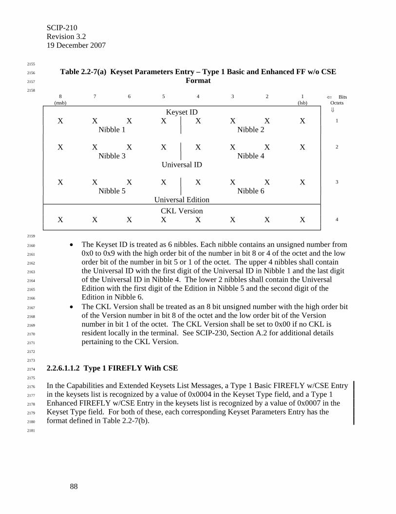
SCIP-210 Revision 3.2 19 December 2007
88
2155
Table 2.2-7(a) Keyset Parameters Entry – Type 1 Basic and Enhanced FF w/o CSE 2156
Format 2157
2158
8 7 6 5 4 3 2 1 ⇐ Bits (msb) (lsb) Octets
Keyset ID ⇓
X X X X X X X X 1
Nibble 1 Nibble 2
X X X X X X X X 2
Nibble 3 Nibble 4
Universal ID
X X X X X X X X 3
Nibble 5 Nibble 6
Universal Edition
CKL Version
X X X X X X X X 4
2159
• The Keyset ID is treated as 6 nibbles. Each nibble contains an unsigned number from 2160
0x0 to 0x9 with the high order bit of the number in bit 8 or 4 of the octet and the low 2161
order bit of the number in bit 5 or 1 of the octet. The upper 4 nibbles shall contain 2162
the Universal ID with the first digit of the Universal ID in Nibble 1 and the last digit 2163
of the Universal ID in Nibble 4. The lower 2 nibbles shall contain the Universal 2164
Edition with the first digit of the Edition in Nibble 5 and the second digit of the 2165
Edition in Nibble 6. 2166
• The CKL Version shall be treated as an 8 bit unsigned number with the high order bit 2167
of the Version number in bit 8 of the octet and the low order bit of the Version 2168
number in bit 1 of the octet. The CKL Version shall be set to 0x00 if no CKL is 2169
resident locally in the terminal. See SCIP-230, Section A.2 for additional details 2170
pertaining to the CKL Version. 2171
2172
2173
2.2.6.1.1.2 Type 1 FIREFLY With CSE 2174
2175
In the Capabilities and Extended Keysets List Messages, a Type 1 Basic FIREFLY w/CSE Entry 2176
in the keysets list is recognized by a value of 0x0004 in the Keyset Type field, and a Type 1 2177
Enhanced FIREFLY w/CSE Entry in the keysets list is recognized by a value of 0x0007 in the 2178
Keyset Type field. For both of these, each corresponding Keyset Parameters Entry has the 2179
format defined in Table 2.2-7(b). 2180
2181
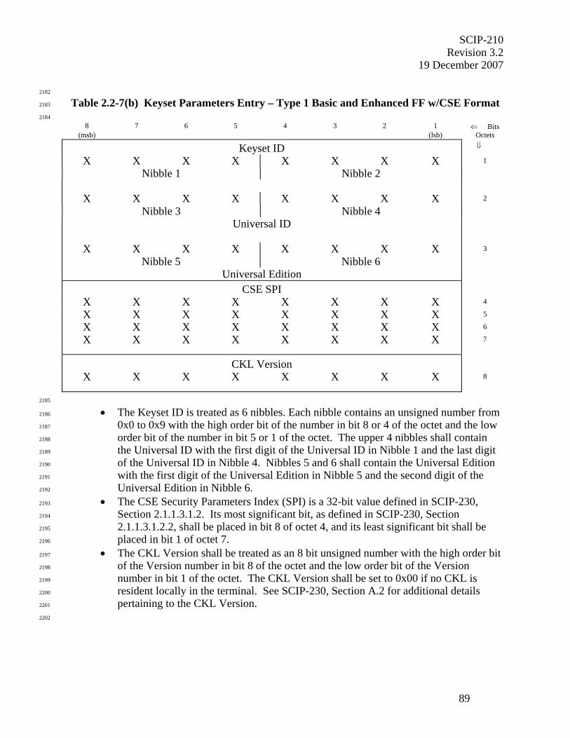
SCIP-210 Revision 3.2
19 December 2007
89
2182
Table 2.2-7(b) Keyset Parameters Entry – Type 1 Basic and Enhanced FF w/CSE Format 2183
2184
8 7 6 5 4 3 2 1 ⇐ Bits (msb) (lsb) Octets
Keyset ID ⇓
X X X X X X X X 1
Nibble 1 Nibble 2
X X X X X X X X 2
Nibble 3 Nibble 4
Universal ID
X X X X X X X X 3
Nibble 5 Nibble 6
Universal Edition
CSE SPI
X X X X X X X X 4
X X X X X X X X 5
X X X X X X X X 6
X X X X X X X X 7
CKL Version
X X X X X X X X 8
2185
• The Keyset ID is treated as 6 nibbles. Each nibble contains an unsigned number from 2186
0x0 to 0x9 with the high order bit of the number in bit 8 or 4 of the octet and the low 2187
order bit of the number in bit 5 or 1 of the octet. The upper 4 nibbles shall contain 2188
the Universal ID with the first digit of the Universal ID in Nibble 1 and the last digit 2189
of the Universal ID in Nibble 4. Nibbles 5 and 6 shall contain the Universal Edition 2190
with the first digit of the Universal Edition in Nibble 5 and the second digit of the 2191
Universal Edition in Nibble 6. 2192
• The CSE Security Parameters Index (SPI) is a 32-bit value defined in SCIP-230, 2193
Section 2.1.1.3.1.2. Its most significant bit, as defined in SCIP-230, Section 2194
2.1.1.3.1.2.2, shall be placed in bit 8 of octet 4, and its least significant bit shall be 2195
placed in bit 1 of octet 7. 2196
• The CKL Version shall be treated as an 8 bit unsigned number with the high order bit 2197
of the Version number in bit 8 of the octet and the low order bit of the Version 2198
number in bit 1 of the octet. The CKL Version shall be set to 0x00 if no CKL is 2199
resident locally in the terminal. See SCIP-230, Section A.2 for additional details 2200
pertaining to the CKL Version. 2201
2202
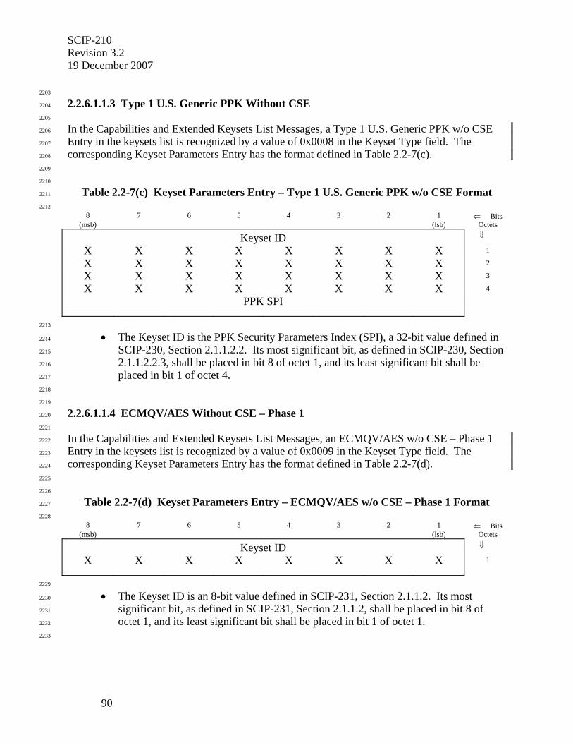
SCIP-210 Revision 3.2 19 December 2007
90
2203
2.2.6.1.1.3 Type 1 U.S. Generic PPK Without CSE 2204
2205
In the Capabilities and Extended Keysets List Messages, a Type 1 U.S. Generic PPK w/o CSE 2206
Entry in the keysets list is recognized by a value of 0x0008 in the Keyset Type field. The 2207
corresponding Keyset Parameters Entry has the format defined in Table 2.2-7(c). 2208
2209
2210
Table 2.2-7(c) Keyset Parameters Entry – Type 1 U.S. Generic PPK w/o CSE Format 2211
2212
8 7 6 5 4 3 2 1 ⇐ Bits (msb) (lsb) Octets
Keyset ID ⇓
X X X X X X X X 1
X X X X X X X X 2
X X X X X X X X 3
X X X X X X X X 4
PPK SPI
2213
• The Keyset ID is the PPK Security Parameters Index (SPI), a 32-bit value defined in 2214
SCIP-230, Section 2.1.1.2.2. Its most significant bit, as defined in SCIP-230, Section 2215
2.1.1.2.2.3, shall be placed in bit 8 of octet 1, and its least significant bit shall be 2216
placed in bit 1 of octet 4. 2217
2218
2219
2.2.6.1.1.4 ECMQV/AES Without CSE – Phase 1 2220
2221
In the Capabilities and Extended Keysets List Messages, an ECMQV/AES w/o CSE – Phase 1 2222
Entry in the keysets list is recognized by a value of 0x0009 in the Keyset Type field. The 2223
corresponding Keyset Parameters Entry has the format defined in Table 2.2-7(d). 2224
2225
2226
Table 2.2-7(d) Keyset Parameters Entry – ECMQV/AES w/o CSE – Phase 1 Format 2227
2228 8 7 6 5 4 3 2 1 ⇐ Bits
(msb) (lsb) Octets
Keyset ID ⇓
X X X X X X X X 1
2229
• The Keyset ID is an 8-bit value defined in SCIP-231, Section 2.1.1.2. Its most 2230
significant bit, as defined in SCIP-231, Section 2.1.1.2, shall be placed in bit 8 of 2231
octet 1, and its least significant bit shall be placed in bit 1 of octet 1. 2232
2233
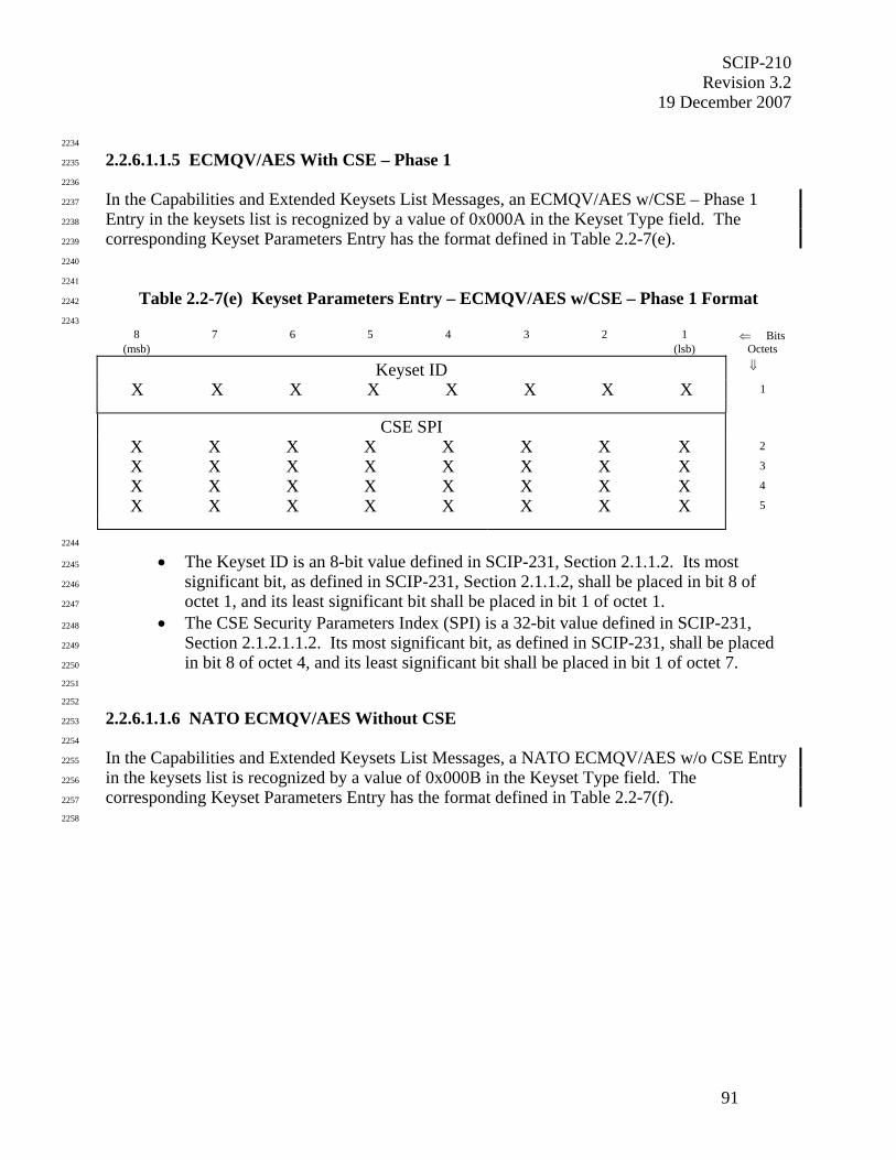
SCIP-210 Revision 3.2
19 December 2007
91
2234
2.2.6.1.1.5 ECMQV/AES With CSE – Phase 1 2235
2236
In the Capabilities and Extended Keysets List Messages, an ECMQV/AES w/CSE – Phase 1 2237
Entry in the keysets list is recognized by a value of 0x000A in the Keyset Type field. The 2238
corresponding Keyset Parameters Entry has the format defined in Table 2.2-7(e). 2239
2240
2241
Table 2.2-7(e) Keyset Parameters Entry – ECMQV/AES w/CSE – Phase 1 Format 2242
2243
8 7 6 5 4 3 2 1 ⇐ Bits (msb) (lsb) Octets
Keyset ID ⇓
X X X X X X X X 1
CSE SPI
X X X X X X X X 2
X X X X X X X X 3
X X X X X X X X 4
X X X X X X X X 5
2244
• The Keyset ID is an 8-bit value defined in SCIP-231, Section 2.1.1.2. Its most 2245
significant bit, as defined in SCIP-231, Section 2.1.1.2, shall be placed in bit 8 of 2246
octet 1, and its least significant bit shall be placed in bit 1 of octet 1. 2247
• The CSE Security Parameters Index (SPI) is a 32-bit value defined in SCIP-231, 2248
Section 2.1.2.1.1.2. Its most significant bit, as defined in SCIP-231, shall be placed 2249
in bit 8 of octet 4, and its least significant bit shall be placed in bit 1 of octet 7. 2250
2251
2252
2.2.6.1.1.6 NATO ECMQV/AES Without CSE 2253
2254
In the Capabilities and Extended Keysets List Messages, a NATO ECMQV/AES w/o CSE Entry 2255
in the keysets list is recognized by a value of 0x000B in the Keyset Type field. The 2256
corresponding Keyset Parameters Entry has the format defined in Table 2.2-7(f). 2257
2258
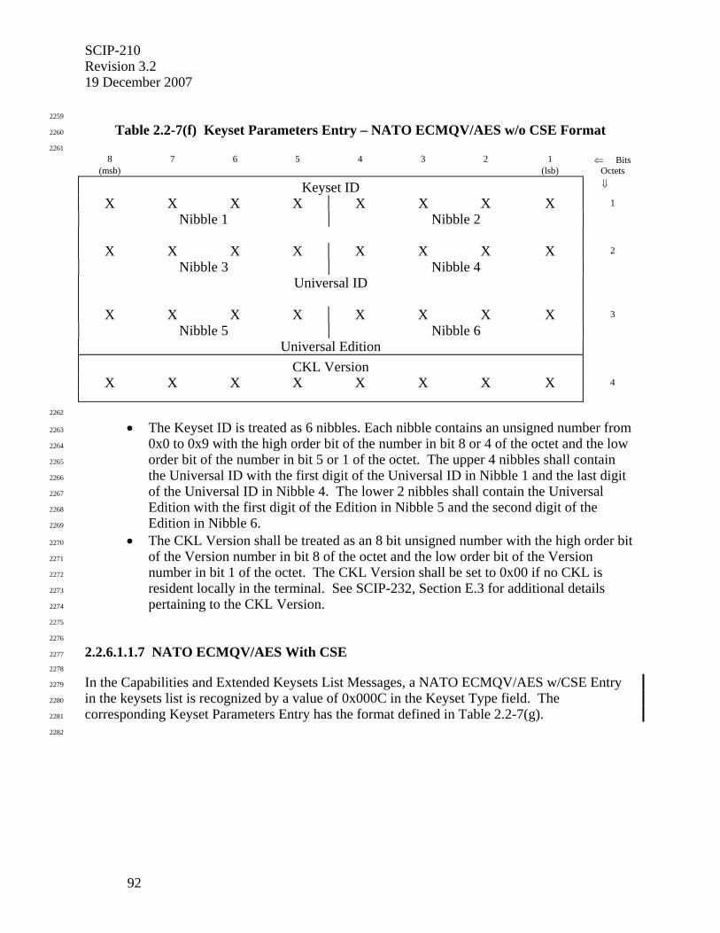
SCIP-210 Revision 3.2 19 December 2007
92
2259
Table 2.2-7(f) Keyset Parameters Entry – NATO ECMQV/AES w/o CSE Format 2260
2261
8 7 6 5 4 3 2 1 ⇐ Bits (msb) (lsb) Octets
Keyset ID ⇓
X X X X X X X X 1
Nibble 1 Nibble 2
X X X X X X X X 2
Nibble 3 Nibble 4
Universal ID
X X X X X X X X 3
Nibble 5 Nibble 6
Universal Edition
CKL Version
X X X X X X X X 4
2262
• The Keyset ID is treated as 6 nibbles. Each nibble contains an unsigned number from 2263
0x0 to 0x9 with the high order bit of the number in bit 8 or 4 of the octet and the low 2264
order bit of the number in bit 5 or 1 of the octet. The upper 4 nibbles shall contain 2265
the Universal ID with the first digit of the Universal ID in Nibble 1 and the last digit 2266
of the Universal ID in Nibble 4. The lower 2 nibbles shall contain the Universal 2267
Edition with the first digit of the Edition in Nibble 5 and the second digit of the 2268
Edition in Nibble 6. 2269
• The CKL Version shall be treated as an 8 bit unsigned number with the high order bit 2270
of the Version number in bit 8 of the octet and the low order bit of the Version 2271
number in bit 1 of the octet. The CKL Version shall be set to 0x00 if no CKL is 2272
resident locally in the terminal. See SCIP-232, Section E.3 for additional details 2273
pertaining to the CKL Version. 2274
2275
2276
2.2.6.1.1.7 NATO ECMQV/AES With CSE 2277
2278
In the Capabilities and Extended Keysets List Messages, a NATO ECMQV/AES w/CSE Entry 2279
in the keysets list is recognized by a value of 0x000C in the Keyset Type field. The 2280
corresponding Keyset Parameters Entry has the format defined in Table 2.2-7(g). 2281
2282
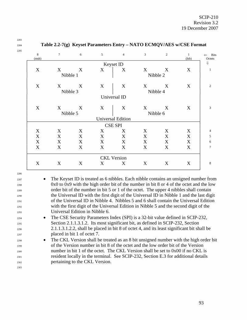
SCIP-210 Revision 3.2
19 December 2007
93
2283
Table 2.2-7(g) Keyset Parameters Entry – NATO ECMQV/AES w/CSE Format 2284
2285
8 7 6 5 4 3 2 1 ⇐ Bits (msb) (lsb) Octets
Keyset ID ⇓
X X X X X X X X 1
Nibble 1 Nibble 2
X X X X X X X X 2
Nibble 3 Nibble 4
Universal ID
X X X X X X X X 3
Nibble 5 Nibble 6
Universal Edition
CSE SPI
X X X X X X X X 4
X X X X X X X X 5
X X X X X X X X 6
X X X X X X X X 7
CKL Version
X X X X X X X X 8
2286
• The Keyset ID is treated as 6 nibbles. Each nibble contains an unsigned number from 2287
0x0 to 0x9 with the high order bit of the number in bit 8 or 4 of the octet and the low 2288
order bit of the number in bit 5 or 1 of the octet. The upper 4 nibbles shall contain 2289
the Universal ID with the first digit of the Universal ID in Nibble 1 and the last digit 2290
of the Universal ID in Nibble 4. Nibbles 5 and 6 shall contain the Universal Edition 2291
with the first digit of the Universal Edition in Nibble 5 and the second digit of the 2292
Universal Edition in Nibble 6. 2293
• The CSE Security Parameters Index (SPI) is a 32-bit value defined in SCIP-232, 2294
Section 2.1.1.3.1.2. Its most significant bit, as defined in SCIP-232, Section 2295
2.1.1.3.1.2.2, shall be placed in bit 8 of octet 4, and its least significant bit shall be 2296
placed in bit 1 of octet 7. 2297
• The CKL Version shall be treated as an 8 bit unsigned number with the high order bit 2298
of the Version number in bit 8 of the octet and the low order bit of the Version 2299
number in bit 1 of the octet. The CKL Version shall be set to 0x00 if no CKL is 2300
resident locally in the terminal. See SCIP-232, Section E.3 for additional details 2301
pertaining to the CKL Version. 2302
2303
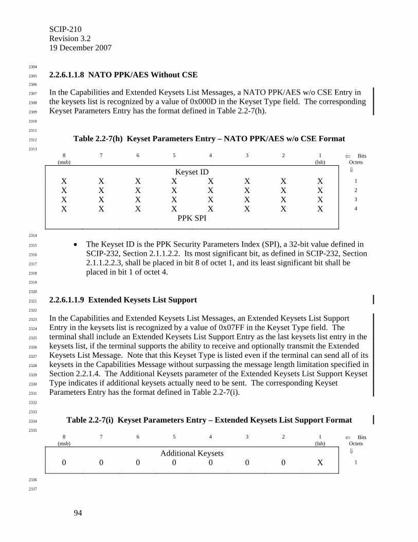
SCIP-210 Revision 3.2 19 December 2007
94
2304
2.2.6.1.1.8 NATO PPK/AES Without CSE 2305
2306
In the Capabilities and Extended Keysets List Messages, a NATO PPK/AES w/o CSE Entry in 2307
the keysets list is recognized by a value of 0x000D in the Keyset Type field. The corresponding 2308
Keyset Parameters Entry has the format defined in Table 2.2-7(h). 2309
2310
2311
Table 2.2-7(h) Keyset Parameters Entry – NATO PPK/AES w/o CSE Format 2312
2313 8 7 6 5 4 3 2 1 ⇐ Bits
(msb) (lsb) Octets
Keyset ID ⇓
X X X X X X X X 1
X X X X X X X X 2
X X X X X X X X 3
X X X X X X X X 4
PPK SPI
2314
• The Keyset ID is the PPK Security Parameters Index (SPI), a 32-bit value defined in 2315
SCIP-232, Section 2.1.1.2.2. Its most significant bit, as defined in SCIP-232, Section 2316
2.1.1.2.2.3, shall be placed in bit 8 of octet 1, and its least significant bit shall be 2317
placed in bit 1 of octet 4. 2318
2319
2320
2.2.6.1.1.9 Extended Keysets List Support 2321
2322
In the Capabilities and Extended Keysets List Messages, an Extended Keysets List Support 2323
Entry in the keysets list is recognized by a value of 0x07FF in the Keyset Type field. The 2324
terminal shall include an Extended Keysets List Support Entry as the last keysets list entry in the 2325
keysets list, if the terminal supports the ability to receive and optionally transmit the Extended 2326
Keysets List Message. Note that this Keyset Type is listed even if the terminal can send all of its 2327
keysets in the Capabilities Message without surpassing the message length limitation specified in 2328
Section 2.2.1.4. The Additional Keysets parameter of the Extended Keysets List Support Keyset 2329
Type indicates if additional keysets actually need to be sent. The corresponding Keyset 2330
Parameters Entry has the format defined in Table 2.2-7(i). 2331
2332
2333
Table 2.2-7(i) Keyset Parameters Entry – Extended Keysets List Support Format 2334
2335 8 7 6 5 4 3 2 1 ⇐ Bits
(msb) (lsb) Octets
Additional Keysets ⇓
0 0 0 0 0 0 0 X 1
2336
2337

SCIP-210 Revision 3.2
19 December 2007
95
• The Additional Keysets parameter shall be set to 0x01 if the terminal has additional 2338
keysets to offer in an Extended Keysets List Message. The Additional Keysets 2339
parameter shall be set to 0x00 if the terminal does not have additional keysets to offer 2340
in an Extended Keysets List Message. 2341
2342
2343
2.2.6.1.2 Parameters/Certificate Message 2344
2345
In the Parameters/Certificate Message, a Certificate has the format defined in Table 2.2-8. 2346
2347
2348
Table 2.2-8 Certificate Field Format 2349
2350 8 7 6 5 4 3 2 1 ⇐ Bits
(msb) (lsb) Octets
Certificate ⇓
X X X X X X X X 1
• • •
X X X X X X X X K
K = Length of Certificate. 2351
2352
2353
2.2.6.1.2.1 Type 1 FIREFLY 2354
2355
In the Parameters/Certificate Message, a Type 1 FIREFLY Keyset ID has the same format as 2356
shown for the Capabilities Message. If the negotiated Keyset Type is Basic FF, the terminal 2357
shall process a received Certificate using the Basic FF rules. If the negotiated Keyset Type is 2358
Enhanced FF, the terminal shall process a received Certificate using the Enhanced FF rules. 2359
Processing rules for both Keyset Types are specified in SCIP-230, Section 2.1.1.4. 2360
2361
The Certificate field shall contain CC1/CC2 for the negotiated Keyset. CC1 shall precede CC2. 2362
The most significant bit of CC1 (as defined in the arithmetic calculation) shall be placed in bit 8 2363
of the first octet, and the least significant bit of CC2 shall be placed in bit 1 of the last octet. 2364
2365
2366
2.2.6.1.2.2 Type 1 U.S. Generic PPK 2367
2368
In the Parameters/Certificate Message, a Type 1 U.S. Generic PPK Keyset ID has the same 2369
format as shown for the Capabilities Message. The Certificate Length field has a value of 2370
0x0002, and the Certificate field is not present in the message. 2371
2372
2373
2.2.6.1.2.3 ECMQV/AES – Phase 1 2374
2375
In the Parameters/Certificate Message, the ECMQV/AES – Phase 1 Keyset ID has the same 2376
format as shown for the Capabilities Message. If the negotiated Keyset Type is ECMQV/AES – 2377
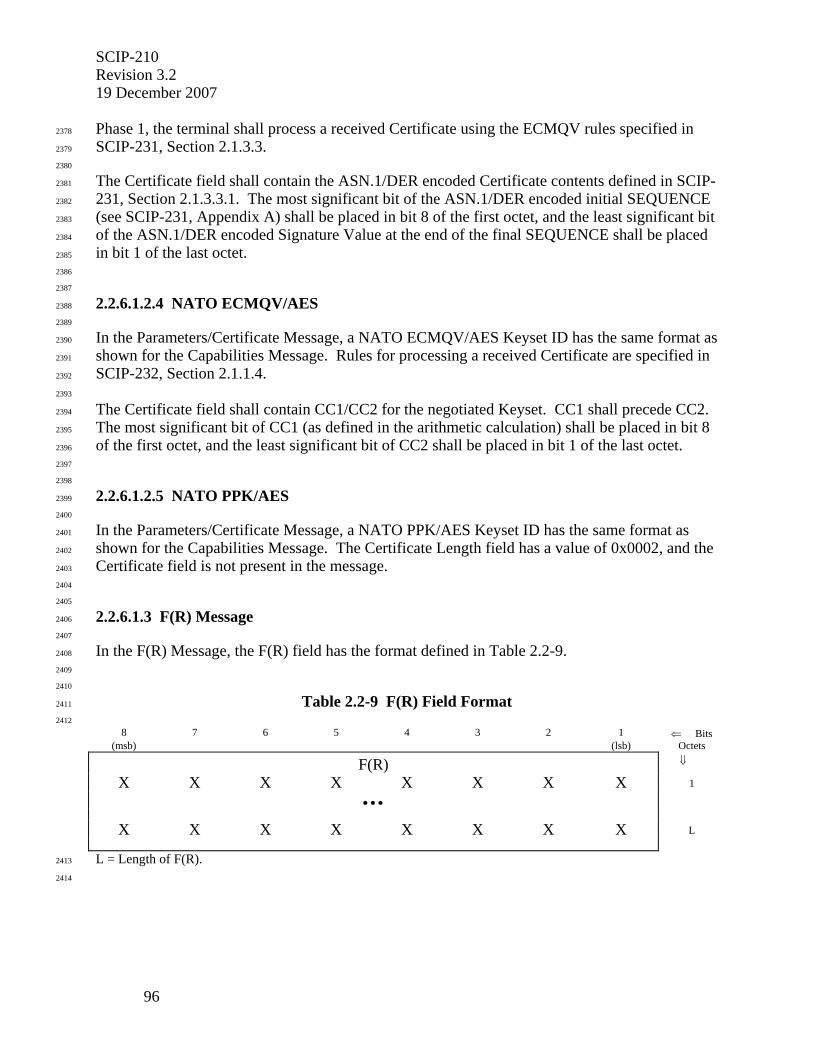
SCIP-210 Revision 3.2 19 December 2007
96
Phase 1, the terminal shall process a received Certificate using the ECMQV rules specified in 2378
SCIP-231, Section 2.1.3.3. 2379
2380
The Certificate field shall contain the ASN.1/DER encoded Certificate contents defined in SCIP-2381
231, Section 2.1.3.3.1. The most significant bit of the ASN.1/DER encoded initial SEQUENCE 2382
(see SCIP-231, Appendix A) shall be placed in bit 8 of the first octet, and the least significant bit 2383
of the ASN.1/DER encoded Signature Value at the end of the final SEQUENCE shall be placed 2384
in bit 1 of the last octet. 2385
2386
2387
2.2.6.1.2.4 NATO ECMQV/AES 2388
2389
In the Parameters/Certificate Message, a NATO ECMQV/AES Keyset ID has the same format as 2390
shown for the Capabilities Message. Rules for processing a received Certificate are specified in 2391
SCIP-232, Section 2.1.1.4. 2392
2393
The Certificate field shall contain CC1/CC2 for the negotiated Keyset. CC1 shall precede CC2. 2394
The most significant bit of CC1 (as defined in the arithmetic calculation) shall be placed in bit 8 2395
of the first octet, and the least significant bit of CC2 shall be placed in bit 1 of the last octet. 2396
2397
2398
2.2.6.1.2.5 NATO PPK/AES 2399
2400
In the Parameters/Certificate Message, a NATO PPK/AES Keyset ID has the same format as 2401
shown for the Capabilities Message. The Certificate Length field has a value of 0x0002, and the 2402
Certificate field is not present in the message. 2403
2404
2405
2.2.6.1.3 F(R) Message 2406
2407
In the F(R) Message, the F(R) field has the format defined in Table 2.2-9. 2408
2409
2410
Table 2.2-9 F(R) Field Format 2411
2412 8 7 6 5 4 3 2 1 ⇐ Bits
(msb) (lsb) Octets
F(R) ⇓
X X X X X X X X 1
• • •
X X X X X X X X L
L = Length of F(R). 2413
2414
SCIP-210 Revision 3.2
19 December 2007
97
2415
2.2.6.1.3.1 Type 1 FIREFLY 2416
2417
In the F(R) Message, a Type 1 FIREFLY Keyset ID has the same format as shown for the 2418
Capabilities Message, and a FIREFLY F(R), calculated as defined in SCIP-230, Section 2.1.1.6, 2419
is included in the F(R) field. If the Keyset Type of the negotiated Keyset is Basic FF, the field 2420
shall contain a Basic FF F(R). If the Keyset Type of the negotiated Keyset is Enhanced FF, the 2421
field shall contain an Enhanced FF F(R). 2422
2423
The F(R) field shall contain either a Basic FF F(R) or an Enhanced FF F(R) for the Universal 2424
Edition negotiated. In terms of SCIP signaling, the only difference is the length of the field. The 2425
F(R)'s most significant bit (as defined in SCIP-230, Section 2.1.1.6) shall be placed in bit 8 of 2426
the first octet, and its least significant bit shall be placed in bit 1 of the L'th octet. 2427
2428
2429
2.2.6.1.3.2 Type 1 U.S. Generic PPK 2430
2431
The F(R) Message does not apply to the Type 1 U.S. Generic PPK Keyset Type. 2432
2433
2434
2.2.6.1.3.3 ECMQV/AES – Phase 1 2435
2436
In the F(R) Message, the ECMQV/AES – Phase 1 Keyset ID has the same format as shown for 2437
the Capabilities Message, and an ECMQV F(R), calculated as defined in SCIP-231, Section 2438
2.1.4, is included in the F(R) field. 2439
2440
The F(R) field shall contain the ECMQV F(R) and a Nonce. The most significant bit of the first 2441
octet of the F(R) (as defined in SCIP-231, Section 2.1.4.3) shall be placed in bit 8 of the first 2442
octet, and the least significant bit of the Nonce shall be placed in bit 1 of the L'th octet. 2443
2444
2445
2.2.6.1.3.4 NATO ECMQV/AES 2446
2447
In the F(R) Message, a NATO ECMQV/AES Keyset ID has the same format as shown for the 2448
Capabilities Message, and an ECMQV F(R), calculated as defined in SCIP-232, Section 2.1.1.6, 2449
is included in the F(R) field. 2450
2451
The F(R) field shall contain an ECMQV F(R) for the Universal Edition negotiated. In terms of 2452
SCIP signaling, the only difference is the length of the field. The ECMQV F(R)'s most 2453
significant bit (as defined in SCIP-232, Section 2.1.1.6) shall be placed in bit 8 of the first octet, 2454
and its least significant bit shall be placed in bit 1 of the L'th octet. 2455
2456
2457
2.2.6.1.3.5 NATO PPK/AES 2458
2459
The F(R) Message does not apply to the NATO PPK/AES Keyset Type. 2460
2461

SCIP-210 Revision 3.2 19 December 2007
98
2462
2.2.6.2 Secure Voice Specifics 2463
2464
Secure Voice is chosen by negotiating Operational Mode 0x0001. 2465
2466
The only Operational Mode specific field is the Operational Mode Parameters for Secure Voice 2467
in the Parameters/Certificate Message. This field has three subfields: Security Levels, Secure 2468
Voice Options List Length, and a Secure Voice Options List. The format of this field for Secure 2469
Voice is given in Table 2.2-10. Note that there may be multiple Secure Voice Options within 2470
this field. 2471
2472
2473
Table 2.2-10 Operational Mode Parameters – Secure Voice 2474
2475 8 7 6 5 4 3 2 1 ⇐ Bits
(msb) (lsb) Octets
Security Levels ⇓
X X X X X X X X 1 Max Min
Secure Voice Options List Length
X-msb X X X X X X X 2
X X X X X X X X-lsb 3
Secure Voice Options List
X-msb X X X X X X X 4 Source ID
X X X X X X X X-lsb 5
First Secure Voice Option ID
• • •
X-msb X X X X X X X 4+2L-2 Source ID
X X X X X X X X-lsb 5+2L-2
L'th Secure Voice Option ID
L = Number of Secure Voice Option Entries. 2476
2477
• The Security Levels field defines a range of security levels compatible with the 2478
Operational Mode. The upper nibble in octet 1 shall identify the Maximum Security 2479
Level, and the lower nibble shall identify the Minimum Security Level for that 2480
combination. The nibble values and corresponding Security Levels are defined in 2481
Table 2.2-11. If a Type 1 Keyset is negotiated, only interoperable security levels in 2482
the Type 1 Keyset ID Family shall be offered. If a Non-Type 1 Keyset is negotiated, 2483
only interoperable security levels in the Non-Type 1 Keyset ID Family shall be 2484
offered. 2485
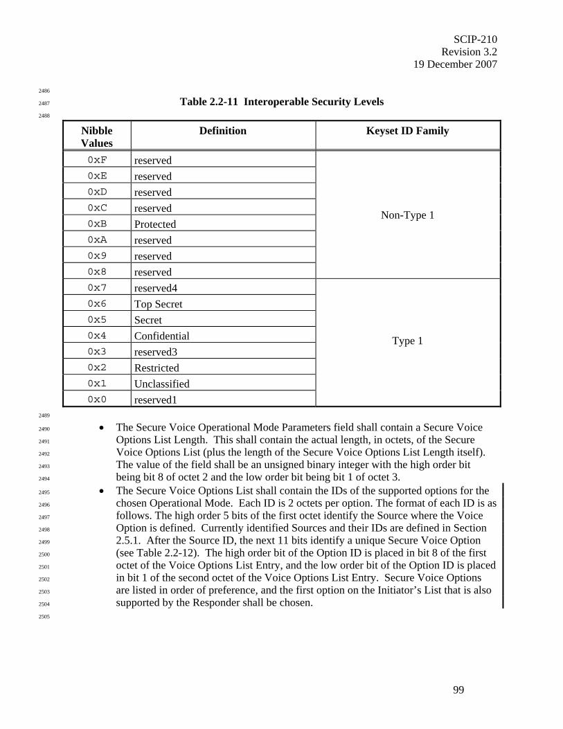
SCIP-210 Revision 3.2
19 December 2007
99
2486
Table 2.2-11 Interoperable Security Levels 2487
2488
Nibble Values
Definition Keyset ID Family
0xF reserved 0xE reserved 0xD reserved 0xC reserved 0xB Protected 0xA reserved 0x9 reserved 0x8 reserved
Non-Type 1
0x7 reserved4 0x6 Top Secret 0x5 Secret 0x4 Confidential 0x3 reserved3 0x2 Restricted 0x1 Unclassified 0x0 reserved1
Type 1
2489
• The Secure Voice Operational Mode Parameters field shall contain a Secure Voice 2490
Options List Length. This shall contain the actual length, in octets, of the Secure 2491
Voice Options List (plus the length of the Secure Voice Options List Length itself). 2492
The value of the field shall be an unsigned binary integer with the high order bit 2493
being bit 8 of octet 2 and the low order bit being bit 1 of octet 3. 2494
• The Secure Voice Options List shall contain the IDs of the supported options for the 2495
chosen Operational Mode. Each ID is 2 octets per option. The format of each ID is as 2496
follows. The high order 5 bits of the first octet identify the Source where the Voice 2497
Option is defined. Currently identified Sources and their IDs are defined in Section 2498
2.5.1. After the Source ID, the next 11 bits identify a unique Secure Voice Option 2499
(see Table 2.2-12). The high order bit of the Option ID is placed in bit 8 of the first 2500
octet of the Voice Options List Entry, and the low order bit of the Option ID is placed 2501
in bit 1 of the second octet of the Voice Options List Entry. Secure Voice Options 2502
are listed in order of preference, and the first option on the Initiator’s List that is also 2503
supported by the Responder shall be chosen. 2504
2505

SCIP-210 Revision 3.2 19 December 2007
100
2506
Table 2.2-12 Secure Voice Options 2507
2508
Option ID Option 0x0002 Secure 2400 bps MELP Voice – Blank & Burst (DTX) 0x0003 Secure 2400 bps MELP Voice – Blank & Burst (FCT) 0x0004 Secure MELP Voice – Burst w/o Blank (DTX) 0x0005 Secure MELP Voice – Burst w/o Blank (FCT) 0x0009 Reserved for compatibility with legacy terminals 0x000E Reserved for Secure G.729F Voice – Burst w/o Blank (DTX) 0x000F Secure G.729D Voice – Burst w/o Blank (FCT) 0x1800 Secure Advanced Multi-Band Excitation (AMBE) Voice
2509
2510
2.2.6.2.1 Secure MELP and Secure G.729D Voice Options 2511
2512
The Secure MELP and Secure G.729D Voice applications are defined in Section 3.3 of this 2513
Signaling Plan. Two options are defined for Secure MELP Voice – Blank and Burst, and Burst 2514
w/o Blank. Only one option is defined for Secure G.729D Voice – Burst w/o Blank. Secure 2515
G.729F Voice is TBSL. 2516
2517
2518
2.2.6.2.2 Secure AMBE Voice Specific Option 2519
2520
Secure Advanced Multi-Band Excitation (AMBE) Voice, as indicated by the Source bits, is a 2521
General Dynamics defined Operational Mode. 2522
2523
2524
2.2.6.3 Secure Data Specifics 2525
2526
Two variants of secure data Operational Modes are defined. Secure Data, specified in Section 2527
2.2.6.3.1, is chosen by negotiating Operational Mode 0x0002. Enhanced Secure Data, specified 2528
in Section 2.2.6.3.2, is chosen by negotiating Operational Mode 0x0003. The difference 2529
between the Operational Modes is that Secure Data has one set of Security Level values that 2530
apply to all data options offered, while Enhanced Secure Data has one set of Security Level 2531
values for each data option offered. 2532
2533
During call setup, one of the two secure data Operational Modes in the Capabilities Messages is 2534
first negotiated and then the associated Operational Mode Parameters in the 2535
Parameters/Certificate Messages are negotiated. During Mode Change, the negotiation takes 2536
place with the Mode Change Request and Response Messages. It is recommended that if a 2537
terminal offers both secure data Operational Modes in the Capabilities Message that Enhanced 2538
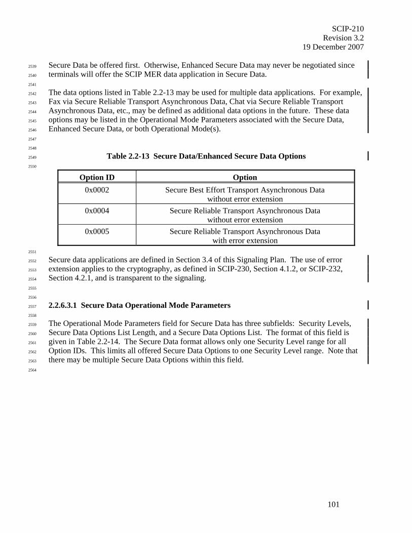
SCIP-210 Revision 3.2
19 December 2007
101
Secure Data be offered first. Otherwise, Enhanced Secure Data may never be negotiated since 2539
terminals will offer the SCIP MER data application in Secure Data. 2540
2541
The data options listed in Table 2.2-13 may be used for multiple data applications. For example, 2542
Fax via Secure Reliable Transport Asynchronous Data, Chat via Secure Reliable Transport 2543
Asynchronous Data, etc., may be defined as additional data options in the future. These data 2544
options may be listed in the Operational Mode Parameters associated with the Secure Data, 2545
Enhanced Secure Data, or both Operational Mode(s). 2546
2547
2548
Table 2.2-13 Secure Data/Enhanced Secure Data Options 2549
2550
Option ID Option 0x0002 Secure Best Effort Transport Asynchronous Data
without error extension 0x0004 Secure Reliable Transport Asynchronous Data
without error extension 0x0005 Secure Reliable Transport Asynchronous Data
with error extension 2551
Secure data applications are defined in Section 3.4 of this Signaling Plan. The use of error 2552
extension applies to the cryptography, as defined in SCIP-230, Section 4.1.2, or SCIP-232, 2553
Section 4.2.1, and is transparent to the signaling. 2554
2555
2556
2.2.6.3.1 Secure Data Operational Mode Parameters 2557
2558
The Operational Mode Parameters field for Secure Data has three subfields: Security Levels, 2559
Secure Data Options List Length, and a Secure Data Options List. The format of this field is 2560
given in Table 2.2-14. The Secure Data format allows only one Security Level range for all 2561
Option IDs. This limits all offered Secure Data Options to one Security Level range. Note that 2562
there may be multiple Secure Data Options within this field. 2563
2564
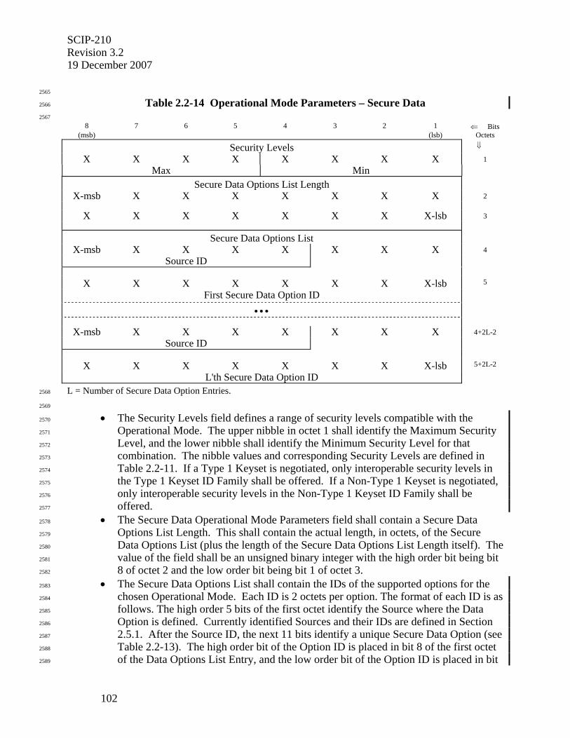
SCIP-210 Revision 3.2 19 December 2007
102
2565
Table 2.2-14 Operational Mode Parameters – Secure Data 2566
2567
8 7 6 5 4 3 2 1 ⇐ Bits (msb) (lsb) Octets
Security Levels ⇓
X X X X X X X X 1 Max Min
Secure Data Options List Length
X-msb X X X X X X X 2
X X X X X X X X-lsb 3
Secure Data Options List
X-msb X X X X X X X 4 Source ID
X X X X X X X X-lsb 5
First Secure Data Option ID
• • •
X-msb X X X X X X X 4+2L-2
Source ID
X X X X X X X X-lsb 5+2L-2
L'th Secure Data Option ID
L = Number of Secure Data Option Entries. 2568
2569
• The Security Levels field defines a range of security levels compatible with the 2570
Operational Mode. The upper nibble in octet 1 shall identify the Maximum Security 2571
Level, and the lower nibble shall identify the Minimum Security Level for that 2572
combination. The nibble values and corresponding Security Levels are defined in 2573
Table 2.2-11. If a Type 1 Keyset is negotiated, only interoperable security levels in 2574
the Type 1 Keyset ID Family shall be offered. If a Non-Type 1 Keyset is negotiated, 2575
only interoperable security levels in the Non-Type 1 Keyset ID Family shall be 2576
offered. 2577
• The Secure Data Operational Mode Parameters field shall contain a Secure Data 2578
Options List Length. This shall contain the actual length, in octets, of the Secure 2579
Data Options List (plus the length of the Secure Data Options List Length itself). The 2580
value of the field shall be an unsigned binary integer with the high order bit being bit 2581
8 of octet 2 and the low order bit being bit 1 of octet 3. 2582
• The Secure Data Options List shall contain the IDs of the supported options for the 2583
chosen Operational Mode. Each ID is 2 octets per option. The format of each ID is as 2584
follows. The high order 5 bits of the first octet identify the Source where the Data 2585
Option is defined. Currently identified Sources and their IDs are defined in Section 2586
2.5.1. After the Source ID, the next 11 bits identify a unique Secure Data Option (see 2587
Table 2.2-13). The high order bit of the Option ID is placed in bit 8 of the first octet 2588
of the Data Options List Entry, and the low order bit of the Option ID is placed in bit 2589
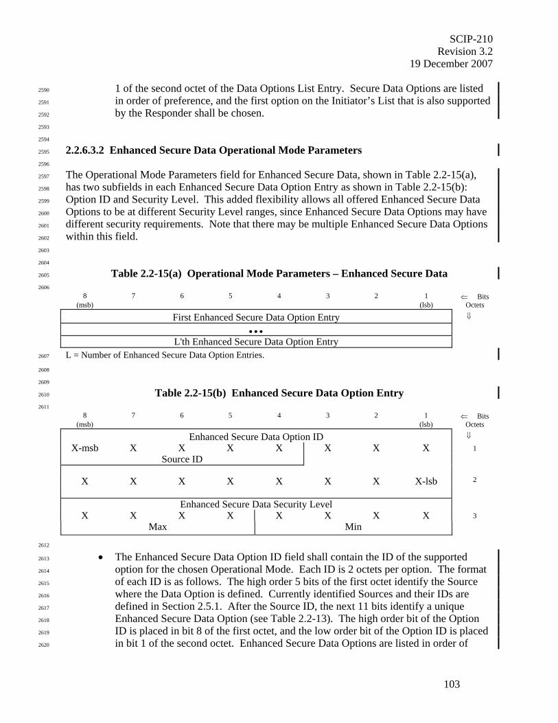
SCIP-210 Revision 3.2
19 December 2007
103
1 of the second octet of the Data Options List Entry. Secure Data Options are listed 2590
in order of preference, and the first option on the Initiator’s List that is also supported 2591
by the Responder shall be chosen. 2592
2593
2594
2.2.6.3.2 Enhanced Secure Data Operational Mode Parameters 2595
2596
The Operational Mode Parameters field for Enhanced Secure Data, shown in Table 2.2-15(a), 2597
has two subfields in each Enhanced Secure Data Option Entry as shown in Table 2.2-15(b): 2598
Option ID and Security Level. This added flexibility allows all offered Enhanced Secure Data 2599
Options to be at different Security Level ranges, since Enhanced Secure Data Options may have 2600
different security requirements. Note that there may be multiple Enhanced Secure Data Options 2601
within this field. 2602
2603
2604
Table 2.2-15(a) Operational Mode Parameters – Enhanced Secure Data 2605
2606 8 7 6 5 4 3 2 1 ⇐ Bits
(msb) (lsb) Octets
First Enhanced Secure Data Option Entry ⇓
• • •
L'th Enhanced Secure Data Option Entry
L = Number of Enhanced Secure Data Option Entries. 2607
2608
2609
Table 2.2-15(b) Enhanced Secure Data Option Entry 2610
2611 8 7 6 5 4 3 2 1 ⇐ Bits
(msb) (lsb) Octets
Enhanced Secure Data Option ID ⇓
X-msb X X X X X X X 1 Source ID
X X X X X X X X-lsb 2
Enhanced Secure Data Security Level
X X X X X X X X 3 Max Min
2612
• The Enhanced Secure Data Option ID field shall contain the ID of the supported 2613
option for the chosen Operational Mode. Each ID is 2 octets per option. The format 2614
of each ID is as follows. The high order 5 bits of the first octet identify the Source 2615
where the Data Option is defined. Currently identified Sources and their IDs are 2616
defined in Section 2.5.1. After the Source ID, the next 11 bits identify a unique 2617
Enhanced Secure Data Option (see Table 2.2-13). The high order bit of the Option 2618
ID is placed in bit 8 of the first octet, and the low order bit of the Option ID is placed 2619
in bit 1 of the second octet. Enhanced Secure Data Options are listed in order of 2620
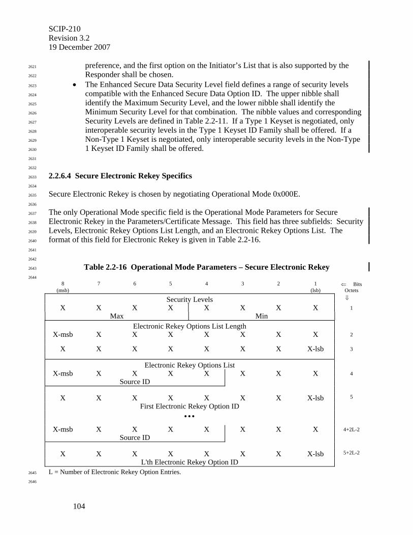
SCIP-210 Revision 3.2 19 December 2007
104
preference, and the first option on the Initiator’s List that is also supported by the 2621
Responder shall be chosen. 2622
• The Enhanced Secure Data Security Level field defines a range of security levels 2623
compatible with the Enhanced Secure Data Option ID. The upper nibble shall 2624
identify the Maximum Security Level, and the lower nibble shall identify the 2625
Minimum Security Level for that combination. The nibble values and corresponding 2626
Security Levels are defined in Table 2.2-11. If a Type 1 Keyset is negotiated, only 2627
interoperable security levels in the Type 1 Keyset ID Family shall be offered. If a 2628
Non-Type 1 Keyset is negotiated, only interoperable security levels in the Non-Type 2629
1 Keyset ID Family shall be offered. 2630
2631
2632
2.2.6.4 Secure Electronic Rekey Specifics 2633
2634
Secure Electronic Rekey is chosen by negotiating Operational Mode 0x000E. 2635
2636
The only Operational Mode specific field is the Operational Mode Parameters for Secure 2637
Electronic Rekey in the Parameters/Certificate Message. This field has three subfields: Security 2638
Levels, Electronic Rekey Options List Length, and an Electronic Rekey Options List. The 2639
format of this field for Electronic Rekey is given in Table 2.2-16. 2640
2641
2642
Table 2.2-16 Operational Mode Parameters – Secure Electronic Rekey 2643
2644 8 7 6 5 4 3 2 1 ⇐ Bits
(msb) (lsb) Octets
Security Levels ⇓
X X X X X X X X 1 Max Min
Electronic Rekey Options List Length
X-msb X X X X X X X 2
X X X X X X X X-lsb 3
Electronic Rekey Options List
X-msb X X X X X X X 4 Source ID
X X X X X X X X-lsb 5
First Electronic Rekey Option ID
• • •
X-msb X X X X X X X 4+2L-2 Source ID
X X X X X X X X-lsb 5+2L-2
L'th Electronic Rekey Option ID
L = Number of Electronic Rekey Option Entries. 2645
2646
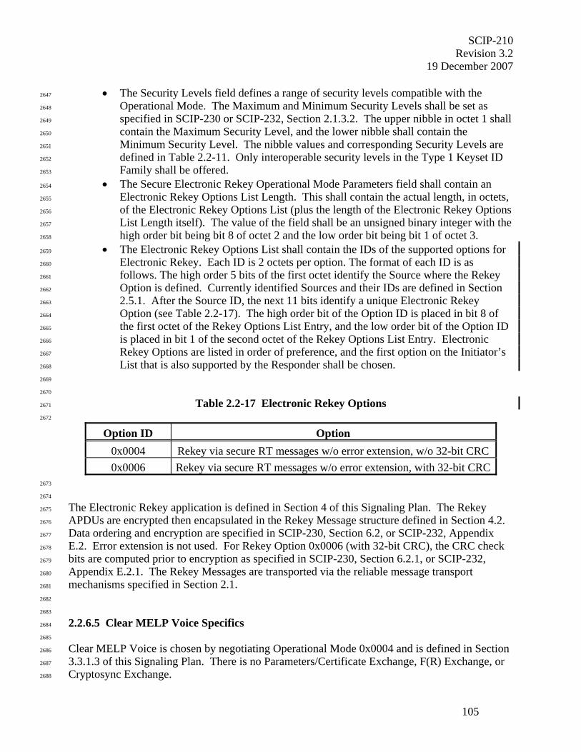
SCIP-210 Revision 3.2
19 December 2007
105
• The Security Levels field defines a range of security levels compatible with the 2647
Operational Mode. The Maximum and Minimum Security Levels shall be set as 2648
specified in SCIP-230 or SCIP-232, Section 2.1.3.2. The upper nibble in octet 1 shall 2649
contain the Maximum Security Level, and the lower nibble shall contain the 2650
Minimum Security Level. The nibble values and corresponding Security Levels are 2651
defined in Table 2.2-11. Only interoperable security levels in the Type 1 Keyset ID 2652
Family shall be offered. 2653
• The Secure Electronic Rekey Operational Mode Parameters field shall contain an 2654
Electronic Rekey Options List Length. This shall contain the actual length, in octets, 2655
of the Electronic Rekey Options List (plus the length of the Electronic Rekey Options 2656
List Length itself). The value of the field shall be an unsigned binary integer with the 2657
high order bit being bit 8 of octet 2 and the low order bit being bit 1 of octet 3. 2658
• The Electronic Rekey Options List shall contain the IDs of the supported options for 2659
Electronic Rekey. Each ID is 2 octets per option. The format of each ID is as 2660
follows. The high order 5 bits of the first octet identify the Source where the Rekey 2661
Option is defined. Currently identified Sources and their IDs are defined in Section 2662
2.5.1. After the Source ID, the next 11 bits identify a unique Electronic Rekey 2663
Option (see Table 2.2-17). The high order bit of the Option ID is placed in bit 8 of 2664
the first octet of the Rekey Options List Entry, and the low order bit of the Option ID 2665
is placed in bit 1 of the second octet of the Rekey Options List Entry. Electronic 2666
Rekey Options are listed in order of preference, and the first option on the Initiator’s 2667
List that is also supported by the Responder shall be chosen. 2668
2669
2670
Table 2.2-17 Electronic Rekey Options 2671
2672
Option ID Option 0x0004 Rekey via secure RT messages w/o error extension, w/o 32-bit CRC 0x0006 Rekey via secure RT messages w/o error extension, with 32-bit CRC
2673
2674
The Electronic Rekey application is defined in Section 4 of this Signaling Plan. The Rekey 2675
APDUs are encrypted then encapsulated in the Rekey Message structure defined in Section 4.2. 2676
Data ordering and encryption are specified in SCIP-230, Section 6.2, or SCIP-232, Appendix 2677
E.2. Error extension is not used. For Rekey Option 0x0006 (with 32-bit CRC), the CRC check 2678
bits are computed prior to encryption as specified in SCIP-230, Section 6.2.1, or SCIP-232, 2679
Appendix E.2.1. The Rekey Messages are transported via the reliable message transport 2680
mechanisms specified in Section 2.1. 2681
2682
2683
2.2.6.5 Clear MELP Voice Specifics 2684
2685
Clear MELP Voice is chosen by negotiating Operational Mode 0x0004 and is defined in Section 2686
3.3.1.3 of this Signaling Plan. There is no Parameters/Certificate Exchange, F(R) Exchange, or 2687
Cryptosync Exchange. 2688

SCIP-210 Revision 3.2 19 December 2007
106
2689
2.3 SCIP Call Control Signaling 2690
2691
When invoked, either by an internal indication or a user-initiated request, the terminal executes 2692
Call Control signaling to perform such functions as terminating a call, changing the application, 2693
alerting the far-end terminal, and cryptographic resynchronization. This section specifies the 2694
signaling for each of the Call Control functions and the interaction between each Call Control 2695
function and the applications active at the time that the Call Control function is executed. Some 2696
Call Control functions, such as Connection Terminate, may be executed at any time; during 2697
application traffic processing, during Call Setup, or even during Call Control processing. Other 2698
Call Control functions, such as Mode Change, are only performed during secure application 2699
traffic processing. 2700
2701
Call Control signaling involves four different messages: Notification, Mode Change Request, 2702
Mode Change Response, and Cryptosync. The Notification Message, with the Action set to 2703
Connection Terminate, Native Clear Voice, Secure Update, or Connection Idle, has a higher 2704
priority and upon receipt shall interrupt Mode Change, Two-Way Resync, CKL Transfer, Secure 2705
Dial, or Attention processing. The priority scheme of the Notification Message is specified in 2706
Section 2.3.2. The remaining Call Control messages, Mode Change Request, Mode Change 2707
Response, Cryptosync, and Notification with the Action set to CKL Transfer, Secure Dial, or 2708
Attention, shall be processed on a first come first served basis. 2709
2710
Call Control messages use the same framed transmission/reception format as specified in Section 2711
2.1. 2712
2713
2714
2.3.1 Call Control Timelines 2715
2716
Examples of Call Control signaling time lines are shown in Figures 2.3-1(a), 2.3-1(b), 2.3-1(c), 2717
2.3-1(d), and 2.3-1(e). Call Control Messages are sent as framed traffic and may interrupt full 2718
bandwidth traffic. Note that these figures are presented from the Message Layer only, thus 2719
ESCAPEs, REPORTs, SOMs, and EOMs are not shown. Refer to Figure 2.1-1(a) for framed 2720
and Figure 2.1-1(b) for full bandwidth Transport Layer operations. Processing of Call Control 2721
Messages will result in terminals going to either framed or full bandwidth formats. If a terminal 2722
is required to enter application traffic, the processing of Section 3 applies. Note that re-entering 2723
a full bandwidth application without the benefit of Cryptosync means that the terminals will not 2724
transmit FILLER. 2725
2726
Examples of Notification Message signaling time lines are shown in Figures 2.3-1(a), 2.3-1(b), 2727
and 2.3-1(c). The examples depicted do not contain any errors, thus require no retransmissions. 2728
Figure 2.3-1(a) is the case where transmitting/receiving the Notification Message (specifically 2729
for the Actions set to Connection Terminate, Native Clear Voice, Secure Update, or Connection 2730
Idle) from full bandwidth traffic results in both terminals going to framed operation. 2731
2732
2733
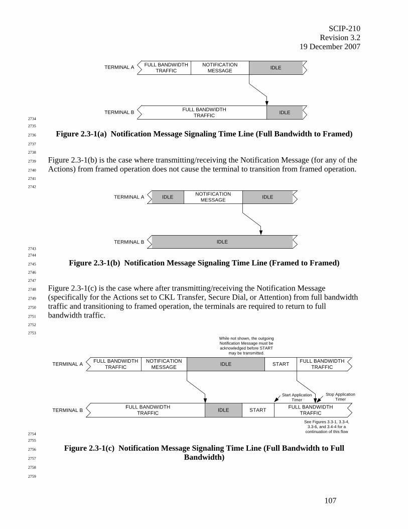
SCIP-210 Revision 3.2
19 December 2007
107
IDLE
IDLETERMINAL A NOTIFICATIONMESSAGE
TERMINAL B
FULL BANDWIDTHTRAFFIC
FULL BANDWIDTHTRAFFIC 2734
2735
Figure 2.3-1(a) Notification Message Signaling Time Line (Full Bandwidth to Framed) 2736
2737
2738
Figure 2.3-1(b) is the case where transmitting/receiving the Notification Message (for any of the 2739
Actions) from framed operation does not cause the terminal to transition from framed operation. 2740
2741
2742
IDLE
IDLE IDLETERMINAL A NOTIFICATIONMESSAGE
TERMINAL B 2743
2744
Figure 2.3-1(b) Notification Message Signaling Time Line (Framed to Framed) 2745
2746
2747
Figure 2.3-1(c) is the case where after transmitting/receiving the Notification Message 2748
(specifically for the Actions set to CKL Transfer, Secure Dial, or Attention) from full bandwidth 2749
traffic and transitioning to framed operation, the terminals are required to return to full 2750
bandwidth traffic. 2751
2752
2753
IDLE
IDLETERMINAL A NOTIFICATIONMESSAGE START
TERMINAL B
FULL BANDWIDTHTRAFFIC
FULL BANDWIDTHTRAFFIC
FULL BANDWIDTHTRAFFIC
START FULL BANDWIDTHTRAFFIC
See Figures 3.3-1, 3.3-4,3.3-6, and 3.4-4 for a
continuation of this flow
While not shown, the outgoingNotification Message must beacknowledged before START
may be transmitted.
Start ApplicationTimer
Stop ApplicationTimer
2754 2755
Figure 2.3-1(c) Notification Message Signaling Time Line (Full Bandwidth to Full 2756
Bandwidth) 2757
2758
2759
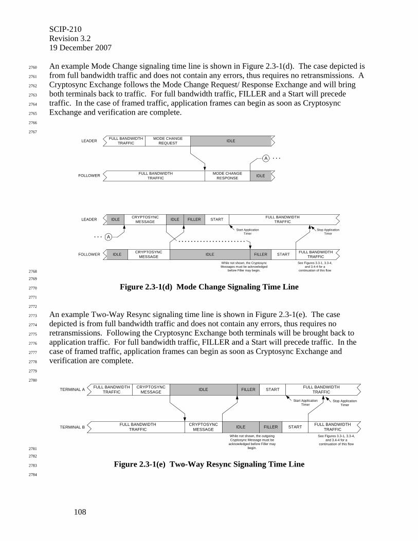
SCIP-210 Revision 3.2 19 December 2007
108
An example Mode Change signaling time line is shown in Figure 2.3-1(d). The case depicted is 2760
from full bandwidth traffic and does not contain any errors, thus requires no retransmissions. A 2761
Cryptosync Exchange follows the Mode Change Request/ Response Exchange and will bring 2762
both terminals back to traffic. For full bandwidth traffic, FILLER and a Start will precede 2763
traffic. In the case of framed traffic, application frames can begin as soon as Cryptosync 2764
Exchange and verification are complete. 2765
2766
2767
FILLER
IDLEIDLE
IDLE
IDLE
IDLEMODE CHANGEREQUEST
FULL BANDWIDTHTRAFFIC
FULL BANDWIDTHTRAFFIC
MODE CHANGERESPONSE
FILLER
IDLE
CRYPTOSYNCMESSAGE START
CRYPTOSYNCMESSAGE
FULL BANDWIDTHTRAFFIC
See Figures 3.3-1, 3.3-4,and 3.4-4 for a
continuation of this flow
While not shown, the CryptosyncMessages must be acknowledged
before Filler may begin.
START FULL BANDWIDTHTRAFFIC
. . . . . . . . . . . . . . . . . . . . . .
Start ApplicationTimer
Stop ApplicationTimer
A . . .
A. . .
LEADER
FOLLOWER
LEADER
FOLLOWER
2768
2769
Figure 2.3-1(d) Mode Change Signaling Time Line 2770
2771
2772
An example Two-Way Resync signaling time line is shown in Figure 2.3-1(e). The case 2773
depicted is from full bandwidth traffic and does not contain any errors, thus requires no 2774
retransmissions. Following the Cryptosync Exchange both terminals will be brought back to 2775
application traffic. For full bandwidth traffic, FILLER and a Start will precede traffic. In the 2776
case of framed traffic, application frames can begin as soon as Cryptosync Exchange and 2777
verification are complete. 2778
2779
2780
FILLERIDLE
FILLERIDLECRYPTOSYNCMESSAGE STARTFULL BANDWIDTH
TRAFFIC
FULL BANDWIDTHTRAFFIC
CRYPTOSYNCMESSAGE
FULL BANDWIDTHTRAFFIC
START FULL BANDWIDTHTRAFFIC
See Figures 3.3-1, 3.3-4,and 3.4-4 for a
continuation of this flow
While not shown, the outgoingCryptosync Message must be
acknowledged before Filler maybegin.
TERMINAL A
TERMINAL B
Start ApplicationTimer
Stop ApplicationTimer
2781
2782
Figure 2.3-1(e) Two-Way Resync Signaling Time Line 2783
2784
SCIP-210 Revision 3.2
19 December 2007
109
2785
2.3.2 Notification Message Processing 2786
2787
This section specifies the processing associated with the Notification Message. The Notification 2788
Message serves several functions and has seven associated Actions to perform these functions: 2789
Connection Terminate, Native Clear Voice, Secure Update, Connection Idle, CKL Transfer, 2790
Secure Dial, and Attention. Notification Messages containing any of these Actions are sent in 2791
the clear. All Notification Messages, except for CKL Transfer, Secure Update, and Secure Dial, 2792
can be sent at any time during call setup. Additionally, all Notification Messages, except for 2793
CKL Transfer, can be sent at any time while a SCIP application is executing. Since sending 2794
Secure Dial requires having a key negotiated and verified, it can only be sent after Cryptosync 2795
Exchange and verification. A terminal requested to perform one of these functions will generate 2796
a local indication for a Notification Message to be formatted and sent to the far end. See Section 2797
2.3.2.1 for the message format. 2798
2799
Section 2.3.2.2 specifies Notification (Connection Terminate) that is used to terminate the data 2800
channel. Section 2.3.2.3 specifies Notification (Native Clear Voice/Connection Idle) processing, 2801
which allows the terminal to revert to clear voice either when an error occurs or when the user 2802
selects “Nonsecure”, or to enter the Connection Idle state if neither Native Clear Voice nor Clear 2803
MELP Voice is available. It also allows a terminal to enter the Connection Idle state when the 2804
user selects “Secure” (from Clear MELP Voice) or when a terminal executes a Secure Restart. 2805
Section 2.3.2.4 specifies Notification (CKL Transfer), which allows a terminal with a later CKL 2806
version to transmit it to a terminal with an earlier one. Section 2.3.2.5 specifies Notification 2807
(Secure Dial), which allows a terminal to transmit encrypted keypad or other dialing data to the 2808
far-end terminal. Section 2.3.2.6 specifies Notification (Attention), which allows a terminal to 2809
alert the far-end user by requesting that the far-end terminal perform a vendor elective action 2810
(e.g., emitting an audible tone, blinking the display, etc.). Section 2.3.2.7 specifies Notification 2811
(Secure Update), which allows terminals executing a secure application to update the current 2812
PPK and return to the same secure application using the updated PPK. 2813
2814
SCIP signaling involves three priority levels. 2815 2816
• The transmission and reception of the Notification (Connection Terminate) Message 2817
(Section 2.3.2.2) is the highest priority process and shall interrupt every other 2818
process. 2819 2820
• The transmission and reception of the Notification Messages related to Failed Call 2821
(Section 2.3.2.3.1), user selection of Nonsecure (Section 2.3.2.3.2), user selection of 2822
Secure (Section 2.3.2.3.3), Secure Restart (Section 2.3.2.3.4), and Secure Update 2823
(Section 2.3.2.7) are the next highest priority processes and shall interrupt all 2824
processes of the lowest priority. Note that in these cases, as with Connection 2825
Terminate, control is not returned to the interrupted process. 2826 2827
• The processes related to the transmission and reception of all other SCIP call setup 2828
and control signaling messages are of lowest priority. Once such a process (e.g., 2829
Mode Change) is started, except for the transmission of Notification Messages, the 2830
process continues to completion before another process may begin. Lowest priority 2831
Notification Messages (i.e., CKL Transfer, Secure Dial, and Attention) may be 2832
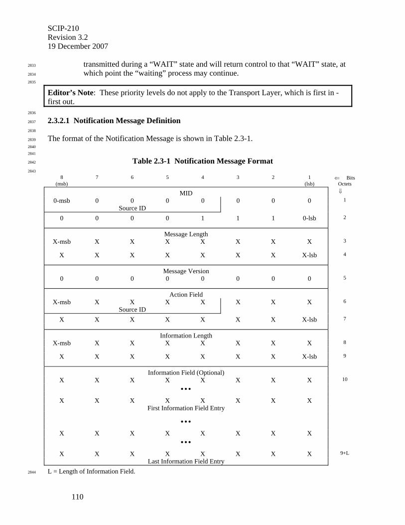
SCIP-210 Revision 3.2 19 December 2007
110
transmitted during a “WAIT” state and will return control to that “WAIT” state, at 2833
which point the “waiting” process may continue. 2834
2835
Editor’s Note: These priority levels do not apply to the Transport Layer, which is first in - first out.
2836
2.3.2.1 Notification Message Definition 2837
2838
The format of the Notification Message is shown in Table 2.3-1. 2839
2840
2841
Table 2.3-1 Notification Message Format 2842
2843 8 7 6 5 4 3 2 1 ⇐ Bits
(msb) (lsb) Octets
MID ⇓
0-msb 0 0 0 0 0 0 0 1
Source ID
0 0 0 0 1 1 1 0-lsb 2
Message Length
X-msb X X X X X X X 3
X X X X X X X X-lsb 4
Message Version
0 0 0 0 0 0 0 0 5
Action Field
X-msb X X X X X X X 6
Source ID
X X X X X X X X-lsb 7
Information Length
X-msb X X X X X X X 8
X X X X X X X X-lsb 9
Information Field (Optional)
X X X X X X X X 10
• • •
X X X X X X X X
First Information Field Entry
• • •
X X X X X X X X
• • •
X X X X X X X X 9+L
Last Information Field Entry
L = Length of Information Field. 2844

SCIP-210 Revision 3.2
19 December 2007
111
2845
• For the Notification Message, the value of the MID is 0x000E. 2846
• The Message Length contains the actual length of the message body (including the 2847
length of the Message Length field itself but not including the length of the MID 2848
field) in octets. The value of the field will be an unsigned binary integer with the 2849
high order bit being bit 8 of octet 3 and the low order bit being bit 1 of octet 4. 2850
• For the version of the Notification Message defined in this version of the Signaling 2851
Plan, the value of the Message Version field is 0x00. 2852
• The Action Field defines the action when a Notification Message is sent. The high 2853
order 5 bits of the first octet constitute a source for the Action Field definition. 2854
Currently identified sources are defined in Section 2.5.1. The next 11 bits constitute 2855
an Action ID. The high order bit of the Action Field is placed in bit 8 of the first 2856
octet of the field and the low order bit is placed in bit 1 of the second octet of the 2857
field. Standard values used for the Action Field are defined in Table 2.3-2. 2858
• The Information Length field contains the actual length of the Information Field (plus 2859
the length of the Information Length field itself) in octets. The value of the field shall 2860
be an unsigned binary integer with the high order bit being bit 8 of octet 8 and the 2861
low order bit being bit 1 of octet 9. 2862
• The Information Field is variable length and contains entries of the form shown in 2863
Table 2.3-3. The Information Field can be sent in any Notification Message, and is 2864
optional for all Action Field values except those for CKL Transfer, Secure Update, 2865
and Secure Dial. Notification Messages used for CKL Transfer, Secure Update, or 2866
Secure Dial shall contain only one Information Field Entry. 2867
2868
2869
Table 2.3-2 SCIP Standard Action Field Values 2870
2871
Action Field Value Action Definition 0x0002 Connection Terminate 0x0004 Native Clear Voice 0x0008 Connection Idle 0x0010 CKL Transfer 0x0020 Secure Dial 0x0040 Attention 0x0080 Secure Update
2872
2873
If a Notification Message is intended to carry only an “Action”, the Action Field is set to the 2874
desired value defined in Table 2.3-2, the Information Length field is set to 0x0002, and the 2875
optional Information Field Entries are not transmitted. 2876
2877
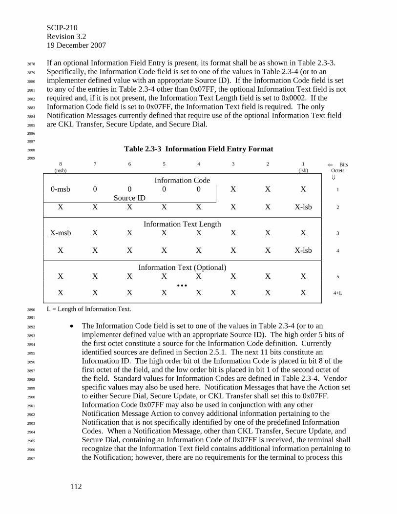
SCIP-210 Revision 3.2 19 December 2007
112
If an optional Information Field Entry is present, its format shall be as shown in Table 2.3-3. 2878
Specifically, the Information Code field is set to one of the values in Table 2.3-4 (or to an 2879
implementer defined value with an appropriate Source ID). If the Information Code field is set 2880
to any of the entries in Table 2.3-4 other than 0x07FF, the optional Information Text field is not 2881
required and, if it is not present, the Information Text Length field is set to 0x0002. If the 2882
Information Code field is set to 0x07FF, the Information Text field is required. The only 2883
Notification Messages currently defined that require use of the optional Information Text field 2884
are CKL Transfer, Secure Update, and Secure Dial. 2885
2886
2887
Table 2.3-3 Information Field Entry Format 2888
2889 8 7 6 5 4 3 2 1 ⇐ Bits
(msb) (lsb) Octets
Information Code ⇓
0-msb 0 0 0 0 X X X 1
Source ID
X X X X X X X X-lsb 2
Information Text Length
X-msb X X X X X X X 3
X X X X X X X X-lsb 4
Information Text (Optional)
X X X X X X X X 5
• • •
X X X X X X X X 4+L
L = Length of Information Text. 2890
2891
• The Information Code field is set to one of the values in Table 2.3-4 (or to an 2892
implementer defined value with an appropriate Source ID). The high order 5 bits of 2893
the first octet constitute a source for the Information Code definition. Currently 2894
identified sources are defined in Section 2.5.1. The next 11 bits constitute an 2895
Information ID. The high order bit of the Information Code is placed in bit 8 of the 2896
first octet of the field, and the low order bit is placed in bit 1 of the second octet of 2897
the field. Standard values for Information Codes are defined in Table 2.3-4. Vendor 2898
specific values may also be used here. Notification Messages that have the Action set 2899
to either Secure Dial, Secure Update, or CKL Transfer shall set this to 0x07FF. 2900
Information Code 0x07FF may also be used in conjunction with any other 2901
Notification Message Action to convey additional information pertaining to the 2902
Notification that is not specifically identified by one of the predefined Information 2903
Codes. When a Notification Message, other than CKL Transfer, Secure Update, and 2904
Secure Dial, containing an Information Code of 0x07FF is received, the terminal shall 2905
recognize that the Information Text field contains additional information pertaining to 2906
the Notification; however, there are no requirements for the terminal to process this 2907
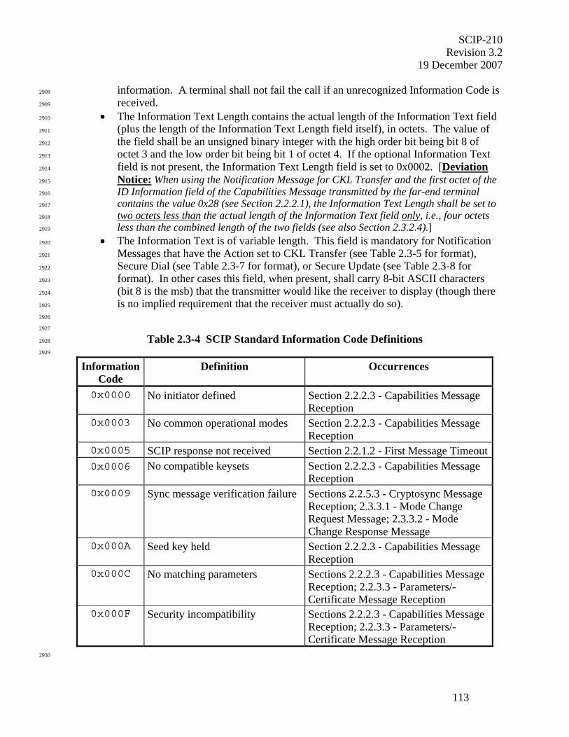
SCIP-210 Revision 3.2
19 December 2007
113
information. A terminal shall not fail the call if an unrecognized Information Code is 2908
received. 2909
• The Information Text Length contains the actual length of the Information Text field 2910
(plus the length of the Information Text Length field itself), in octets. The value of 2911
the field shall be an unsigned binary integer with the high order bit being bit 8 of 2912
octet 3 and the low order bit being bit 1 of octet 4. If the optional Information Text 2913
field is not present, the Information Text Length field is set to 0x0002. [Deviation 2914
Notice: When using the Notification Message for CKL Transfer and the first octet of the 2915
ID Information field of the Capabilities Message transmitted by the far-end terminal 2916
contains the value 0x28 (see Section 2.2.2.1), the Information Text Length shall be set to 2917
two octets less than the actual length of the Information Text field only, i.e., four octets 2918
less than the combined length of the two fields (see also Section 2.3.2.4).] 2919
• The Information Text is of variable length. This field is mandatory for Notification 2920
Messages that have the Action set to CKL Transfer (see Table 2.3-5 for format), 2921
Secure Dial (see Table 2.3-7 for format), or Secure Update (see Table 2.3-8 for 2922
format). In other cases this field, when present, shall carry 8-bit ASCII characters 2923
(bit 8 is the msb) that the transmitter would like the receiver to display (though there 2924
is no implied requirement that the receiver must actually do so). 2925
2926
2927
Table 2.3-4 SCIP Standard Information Code Definitions 2928
2929
Information Code
Definition Occurrences
0x0000 No initiator defined Section 2.2.2.3 - Capabilities Message Reception
0x0003 No common operational modes Section 2.2.2.3 - Capabilities Message Reception
0x0005 SCIP response not received Section 2.2.1.2 - First Message Timeout0x0006 No compatible keysets Section 2.2.2.3 - Capabilities Message
Reception 0x0009 Sync message verification failure Sections 2.2.5.3 - Cryptosync Message
Reception; 2.3.3.1 - Mode Change Request Message; 2.3.3.2 - Mode Change Response Message
0x000A Seed key held Section 2.2.2.3 - Capabilities Message Reception
0x000C No matching parameters Sections 2.2.2.3 - Capabilities Message Reception; 2.2.3.3 - Parameters/-Certificate Message Reception
0x000F Security incompatibility Sections 2.2.2.3 - Capabilities Message Reception; 2.2.3.3 - Parameters/-Certificate Message Reception
2930

SCIP-210 Revision 3.2 19 December 2007
114
2931
Table 2.3-4 SCIP Standard Information Code Definitions (Cont.) 2932
2933
Information Code
Definition Occurrences
0x0011 Certificate verification failure Section 2.2.3.3 - Parameters/Certificate Message Reception
0x0012 Certificate expired Section 2.2.3.3 - Parameters/Certificate Message Reception
0x0014 Access Control failure Sections 2.2.2.3 - Capabilities Message Reception; 2.2.3.3 -Parameters/-Certificate Message Reception
0x0017 Rekey Message CRC failure Section 4.3 - Adaptation Layer 0x0018 Local CSE key expired Section 2.2.3.2 - Parameters/Certificate
Message Transmission 0x0041 Cryptosync/Mode Change glare Section 2.3.3.1 - Mode Change Request
Message; Section 2.3.4 - Two-Way Resync Processing
0x0042 Secure Restart Section 2.3.2.3.4 - Secure Restart 0x07FF Defined by Information Text
field(s) Sections 2.3.2.4, 2.3.2.5, and 2.3.2.7 - CKL Transfer, Secure Dial, and Secure Update, respectively; Section 2.3.2.1 for implementer defined display data
2934
2935
2.3.2.2 Notification (Connection Terminate) 2936
2937
Connection Terminate shall be available from any state during a call. Note that Connection 2938
Terminate is a state native to the underlying network in which the data channel is terminated. As 2939
such, it is outside the scope of SCIP-210 to specify how the network will terminate the data 2940
channel. Thus, Connection Terminate will only bring a terminal to the Connection Idle state 2941
with the provision that the network takes care of terminating the data channel. It is invoked 2942
when a terminal receives a local indication to terminate the connection. The Connection 2943
Terminate processing is shown in Figure 2.3-2. 2944
2945
Upon receipt of an indication to terminate the connection, the terminal shall format a 2946
Notification Message as shown in Table 2.3-1, with the Action set to Connection Terminate. 2947
The terminal will transmit this Notification Message to the far end and immediately enter the 2948
Connection Idle state. 2949
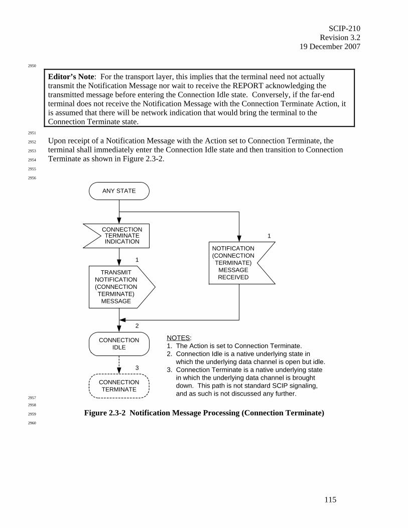
SCIP-210 Revision 3.2
19 December 2007
115
2950
Editor’s Note: For the transport layer, this implies that the terminal need not actually transmit the Notification Message nor wait to receive the REPORT acknowledging the transmitted message before entering the Connection Idle state. Conversely, if the far-end terminal does not receive the Notification Message with the Connection Terminate Action, it is assumed that there will be network indication that would bring the terminal to the Connection Terminate state.
2951
Upon receipt of a Notification Message with the Action set to Connection Terminate, the 2952
terminal shall immediately enter the Connection Idle state and then transition to Connection 2953
Terminate as shown in Figure 2.3-2. 2954
2955
2956
CONNECTIONTERMINATEINDICATION
ANY STATE
1
CONNECTIONIDLE
1
2
CONNECTIONTERMINATE
3
TRANSMITNOTIFICATION(CONNECTIONTERMINATE)
MESSAGE
NOTIFICATION(CONNECTIONTERMINATE)
MESSAGERECEIVED
NOTES:1. The Action is set to Connection Terminate.2. Connection Idle is a native underlying state in which the underlying data channel is open but idle.3. Connection Terminate is a native underlying state in which the underlying data channel is brought down. This path is not standard SCIP signaling, and as such is not discussed any further. 2957
2958
Figure 2.3-2 Notification Message Processing (Connection Terminate) 2959
2960
SCIP-210 Revision 3.2 19 December 2007
116
2961
2.3.2.3 Notification (Native Clear Voice/Connection Idle) 2962
2963
Notification Messages with Actions for Native Clear Voice and Connection Idle are used to 2964
perform four functions: Failed Call, Nonsecure Selected, Secure Selected, and Secure Restart. 2965
These functions are described in Section 2.3.2.3.1, Section 2.3.2.3.2, Section 2.3.2.3.3, and 2966
Section 2.3.2.3.4, respectively. Notification (Native Clear Voice/Connection Idle) receive 2967
processing is described in Section 2.3.2.3.5. The Actions for Native Clear Voice and Connection 2968
Idle shall be available from the indicated states during a call, except when the terminal is already 2969
processing a Notification (Connection Terminate) or a Notification (Native Clear Voice/-2970
Connection Idle). The Notification (Native Clear Voice/Connection Idle) processing is shown in 2971
Figure 2.3-3. 2972
2973
2974
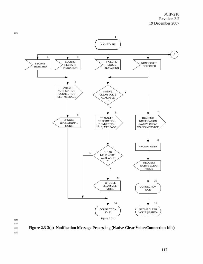
SCIP-210 Revision 3.2
19 December 2007
117
2975
1
ANY STATE
FAILUREREQUEST
INDICATION
NONSECURESELECTED
10
Figure 2.2-2
9
CHOOSECLEAR MELP
VOICE
CONNECTIONIDLE
N
Y
CLEARMELP VOICEAVAILABLE
?
YNATIVECLEAR VOICE
AVAILABLE?
5
N
TRANSMITNOTIFICATION(CONNECTION
IDLE) MESSAGE
SECURERESTART
INDICATION
SECURESELECTED
5
TRANSMITNOTIFICATION(CONNECTION
IDLE) MESSAGE
CHOOSEOPERATIONAL
MODE
6
PROMPT USER
REQUESTNATIVE CLEAR
VOICE
8
10
CONNECTIONIDLE
NATIVE CLEARVOICE (MUTED)
11
TRANSMITNOTIFICATION(NATIVE CLEAR
VOICE) MESSAGE
7
A2 3
2976
2977
Figure 2.3-3(a) Notification Message Processing (Native Clear Voice/Connection Idle) 2978
2979
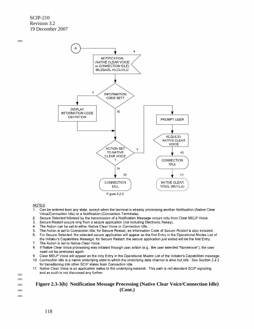
SCIP-210 Revision 3.2 19 December 2007
118
2980
2981
2982
Figure 2.3-3(b) Notification Message Processing (Native Clear Voice/Connection Idle) 2983
(Cont.) 2984
2985

SCIP-210 Revision 3.2
19 December 2007
119
2986
2.3.2.3.1 Failed Call 2987
2988
Failed Call uses the Action of either Native Clear Voice, if available, or Connection Idle, 2989
otherwise. Native Clear Voice is an application native to the underlying network providing the 2990
data channel. As such, it is outside the scope of this Signaling Plan to specify how the network 2991
will handle transitions into it. Thus, Native Clear Voice will only bring a terminal to the 2992
Connection Idle state with the provision that the network takes care of transitioning into a clear 2993
voice application native to it. Connection Idle is a state native to the underlying network in 2994
which the data channel is alive but idle. Failed Call is invoked when a terminal receives a local 2995
Failure Request indication (e.g., as a result of internal error detection). 2996
2997
Upon receipt of a local Failure Request indication, the terminal shall format a Notification 2998
Message as shown in Table 2.3-1, with the Action set to either Native Clear Voice or Connection 2999
Idle. From the Capabilities Message Exchange of call setup (see Section 2.2.2), a terminal 3000
knows which clear applications it has in common with the far end. This information will be 3001
retained from call setup and made available for Failed Call processing. 3002
3003
• If both the local and remote terminals support Native Clear Voice, the local terminal shall 3004
format a Notification Message with the Action set to Native Clear Voice, transmit it to 3005
the far end, prompt the user, generate a local request to enter Native Clear Voice, and 3006
immediately enter the Connection Idle state. 3007
3008
Editor’s Note: For Native Clear Voice, at the Transport Layer the terminal need not wait to receive the acknowledgment for the transmitted message before entering the Connection Idle state. Conversely, if the far-end terminal does not receive the Notification Message with the Native Clear Voice Action, it is assumed that there will be a network indication which would bring the terminal to Native Clear Voice. Note that even in the case where a terminal enters Native Clear Voice as a result of a network indication, the user must first acknowledge the transition.
3009
• If Native Clear Voice is not available, the local terminal shall format a Notification 3010
Message with the Action set to Connection Idle and transmit it to the far end. 3011
3012
◊ If both the local and remote terminals support Clear MELP Voice, the terminal shall 3013
generate a local request to enter Clear MELP Voice and go to the Connection Idle 3014
state. From the Connection Idle state, the terminal will request Clear MELP Voice by 3015
transmitting a Capabilities Message, with Clear MELP Voice as the only Operational 3016
Mode offered, in accordance with the signaling specified in Section 2.2.2. Clear 3017
MELP Voice is described in Section 3.3.1.3. 3018
3019
◊ If the local and remote terminals have no clear voice application in common, the local 3020
terminal shall go to the Connection Idle state. 3021
3022
SCIP-210 Revision 3.2 19 December 2007
120
3023
2.3.2.3.2 Nonsecure Selected 3024
3025
Nonsecure Selected shall be identical to Failed Call except that it is invoked when a terminal 3026
receives a local Nonsecure Selected indication (e.g., as the result of the user selecting 3027
“Nonsecure”). Additionally, the terminal receiving the local Nonsecure Selected indication will 3028
not prompt the user prior to entering the Connection Idle state. 3029
3030
3031
2.3.2.3.3 Secure Selected 3032
3033
Secure Selected uses only the Action of Connection Idle. Secure Selected is invoked from Clear 3034
MELP Voice when a terminal receives a local Secure Selected indication (e.g., as the result of 3035
the user selecting “Secure”). 3036
3037
Upon receipt of a local Secure Selected indication, the terminal shall format a Notification 3038
Message as shown in Table 2.3-1, with the Action set to Connection Idle, and transmit it to the 3039
far end. The terminal shall then generate a local request to enter an Operational Mode with the 3040
selected mode as the preferred mode, and go to the Connection Idle state. From the Connection 3041
Idle state, the terminal will then enter secure call setup by transmitting a Capabilities Message in 3042
accordance with the signaling specified in Section 2.2.2. 3043
3044
3045
2.3.2.3.4 Secure Restart 3046
3047
Secure Restart provides the capability for terminals executing a secure application to generate a 3048
new traffic encryption key using the FIREFLY or ECMQV Key Exchange and return to the same 3049
secure application. Secure Restart is invoked when a terminal in a secure application, other than 3050
Electronic Rekey, receives a local Secure Restart indication (e.g., for the case described in SCIP-3051
230, Section 3.3.1, SCIP-231, Section 3.1.4.1, or SCIP-232, Section 3.4.1). 3052
3053
Upon receipt of a local Secure Restart indication, the (Leader) terminal shall format a 3054
Notification Message as shown in Table 2.3-1, with the Action set to Connection Idle and an 3055
Information Code of Secure Restart, and transmit it to the far end. The Leader terminal shall 3056
then generate a local request to enter an Operational Mode with the mode and parameter option 3057
just exited as the preferred mode and option, and go to the Connection Idle state. From the 3058
Connection Idle state, the Leader terminal shall enter secure call setup by transmitting a 3059
Capabilities Message with the I/R bits set to Initiator in accordance with the signaling specified 3060
in Section 2.2.2. In this Capabilities Message, the Leader terminal shall offer only FIREFLY or 3061
NATO ECMQV/AES Keysets with the same KMID, or the ECMQV/AES Keyset that was in use 3062
prior to the Secure Restart. 3063
3064
The Secure Restart Follower terminal, after receiving the Notification (Connection Idle) 3065
Message waits in the Connection Idle state until it receives the Capabilities Message transmitted 3066
by the Leader. Secure call setup then proceeds in the same manner as for any secure call with 3067
the I/R bits set to Responder in the Capabilities Message transmitted by the Follower terminal. 3068
SCIP-210 Revision 3.2
19 December 2007
121
3069
If the classification is changed in a Secure Restart, both the Leader and Follower terminals shall 3070
prompt the user and wait for an acknowledgment before transmitting secure traffic. Secure 3071
Restart places no other special requirements on the Follower terminal. 3072
3073
3074
2.3.2.3.5 Notification (Native Clear Voice/Connection Idle) Receive Processing 3075
3076
Upon receipt of a Notification (Native Clear Voice/Connection Idle) Message, the terminal shall 3077
determine whether an Information Code is included. If an Information Code is included, the 3078
terminal will display a text message locally associated with the value contained in the 3079
Information Code field. (Implementers are permitted to associate different locally defined 3080
display texts with the Standard Information Codes contained in Table 2.3-4 so long as the text 3081
conveys the intended meaning of the code to the user.) The terminal will also determine whether 3082
Information Text is included. Information Text received in a Notification Message is text that 3083
the transmitter intends be displayed to the user (though this Signaling Plan levies no requirement 3084
on the recipient terminal to actually display this text). The terminal shall then examine the 3085
Action field. If the Action is set to Native Clear Voice, the terminal shall prompt the user, 3086
generate a local request to enter Native Clear Voice, and immediately enter the Connection Idle 3087
state. If the Action is set to Connection Idle, the terminal shall go to the Connection Idle state. 3088
From the Connection Idle state, the terminal will wait for the receipt of a Capabilities Message 3089
and then enter SCIP call setup in accordance with the signaling specified in Section 2.2.2. 3090
3091
3092
2.3.2.4 Notification (CKL Transfer) 3093
3094
CKL Transfer allows a terminal to transmit its CKL to the far-end terminal. During secure call 3095
setup, the versions of the CKL held by both terminals are compared. If the local terminal's CKL 3096
version is later than that of the far-end terminal, the local terminal transmits its CKL to the far-3097
end terminal (see Sections 2.2.5.2 and 2.2.5.3). 3098
3099
Since the CKL is large, it may be segmented and transmitted in multiple Notification Messages. 3100
Of course, the entire CKL may be transmitted as a single segment in a single Notification 3101
Message. Rules for segmenting the CKL are left to the implementer since, while they may 3102
impact performance, such rules do not impact interoperability. 3103
3104
This section describes the processing of a single Notification Message containing a single CKL 3105
segment. If the CKL has been segmented for transmission, the process described below shall be 3106
performed as many times as there are segments. 3107
3108
CKL Transfer shall be available only during SCIP Call Setup after a Cryptosync Message has 3109
been received and before the locally generated Cryptosync Message has been transmitted (see 3110
Figure 2.2-10). 3111
3112
Upon the local determination that a CKL Transfer is required, the terminal shall format a 3113
Notification Message as shown in Table 2.3-1, with the Action set to CKL Transfer and the 3114
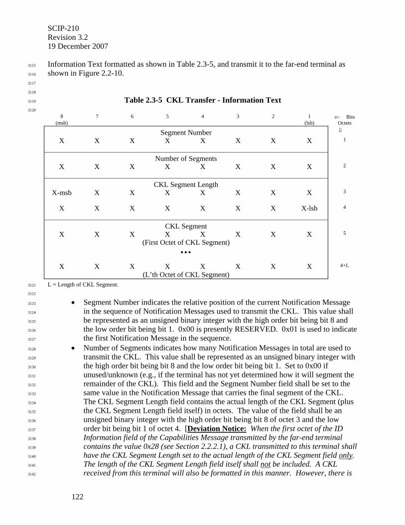
SCIP-210 Revision 3.2 19 December 2007
122
Information Text formatted as shown in Table 2.3-5, and transmit it to the far-end terminal as 3115
shown in Figure 2.2-10. 3116
3117
3118
Table 2.3-5 CKL Transfer - Information Text 3119
3120
8 7 6 5 4 3 2 1 ⇐ Bits (msb) (lsb) Octets
Segment Number ⇓
X X X X X X X X 1
Number of Segments
X X X X X X X X 2
CKL Segment Length
X-msb X X X X X X X 3
X X X X X X X X-lsb 4
CKL Segment
X X X X X X X X 5
(First Octet of CKL Segment)
• • •
X X X X X X X X 4+L
(L’th Octet of CKL Segment)
L = Length of CKL Segment. 3121
3122
• Segment Number indicates the relative position of the current Notification Message 3123
in the sequence of Notification Messages used to transmit the CKL. This value shall 3124
be represented as an unsigned binary integer with the high order bit being bit 8 and 3125
the low order bit being bit 1. 0x00 is presently RESERVED. 0x01 is used to indicate 3126
the first Notification Message in the sequence. 3127
• Number of Segments indicates how many Notification Messages in total are used to 3128
transmit the CKL. This value shall be represented as an unsigned binary integer with 3129
the high order bit being bit 8 and the low order bit being bit 1. Set to 0x00 if 3130
unused/unknown (e.g., if the terminal has not yet determined how it will segment the 3131
remainder of the CKL). This field and the Segment Number field shall be set to the 3132
same value in the Notification Message that carries the final segment of the CKL. 3133
The CKL Segment Length field contains the actual length of the CKL Segment (plus 3134
the CKL Segment Length field itself) in octets. The value of the field shall be an 3135
unsigned binary integer with the high order bit being bit 8 of octet 3 and the low 3136
order bit being bit 1 of octet 4. [Deviation Notice: When the first octet of the ID 3137
Information field of the Capabilities Message transmitted by the far-end terminal 3138
contains the value 0x28 (see Section 2.2.2.1), a CKL transmitted to this terminal shall 3139
have the CKL Segment Length set to the actual length of the CKL Segment field only. 3140
The length of the CKL Segment Length field itself shall not be included. A CKL 3141
received from this terminal will also be formatted in this manner. However, there is 3142
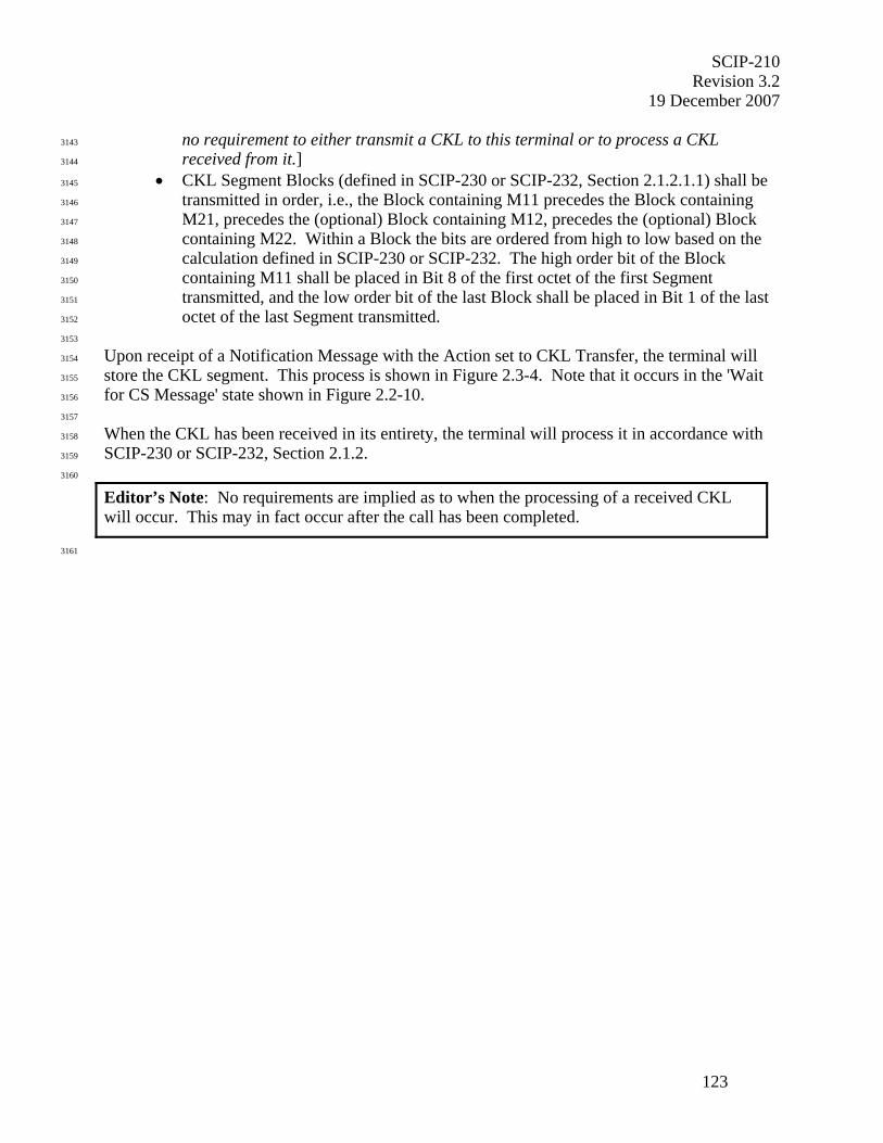
SCIP-210 Revision 3.2
19 December 2007
123
no requirement to either transmit a CKL to this terminal or to process a CKL 3143
received from it.] 3144
• CKL Segment Blocks (defined in SCIP-230 or SCIP-232, Section 2.1.2.1.1) shall be 3145
transmitted in order, i.e., the Block containing M11 precedes the Block containing 3146
M21, precedes the (optional) Block containing M12, precedes the (optional) Block 3147
containing M22. Within a Block the bits are ordered from high to low based on the 3148
calculation defined in SCIP-230 or SCIP-232. The high order bit of the Block 3149
containing M11 shall be placed in Bit 8 of the first octet of the first Segment 3150
transmitted, and the low order bit of the last Block shall be placed in Bit 1 of the last 3151
octet of the last Segment transmitted. 3152
3153
Upon receipt of a Notification Message with the Action set to CKL Transfer, the terminal will 3154
store the CKL segment. This process is shown in Figure 2.3-4. Note that it occurs in the 'Wait 3155
for CS Message' state shown in Figure 2.2-10. 3156
3157
When the CKL has been received in its entirety, the terminal will process it in accordance with 3158
SCIP-230 or SCIP-232, Section 2.1.2. 3159
3160
Editor’s Note: No requirements are implied as to when the processing of a received CKL will occur. This may in fact occur after the call has been completed.
3161
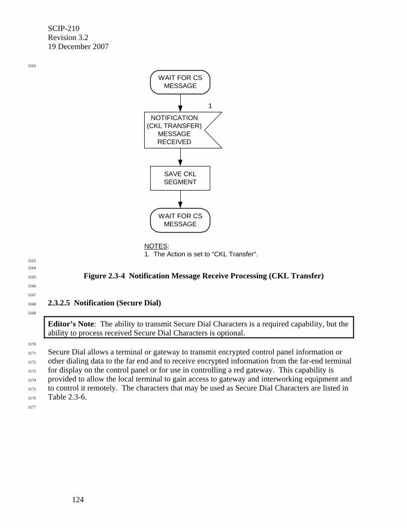
SCIP-210 Revision 3.2 19 December 2007
124
3162
NOTES:1. The Action is set to "CKL Transfer".
NOTIFICATION(CKL TRANSFER)
MESSAGERECEIVED
1
WAIT FOR CSMESSAGE
SAVE CKLSEGMENT
WAIT FOR CSMESSAGE
3163
3164
Figure 2.3-4 Notification Message Receive Processing (CKL Transfer) 3165
3166
3167
2.3.2.5 Notification (Secure Dial) 3168
3169
Editor’s Note: The ability to transmit Secure Dial Characters is a required capability, but the ability to process received Secure Dial Characters is optional.
3170
Secure Dial allows a terminal or gateway to transmit encrypted control panel information or 3171
other dialing data to the far end and to receive encrypted information from the far-end terminal 3172
for display on the control panel or for use in controlling a red gateway. This capability is 3173
provided to allow the local terminal to gain access to gateway and interworking equipment and 3174
to control it remotely. The characters that may be used as Secure Dial Characters are listed in 3175
Table 2.3-6. 3176
3177
SCIP-210 Revision 3.2
19 December 2007
125
3178
Table 2.3-6 Secure Dial Characters 3179
3180
ASCII character (8 bit format)
Definition
0-9 0-9 * * # # T change to TONE dialing mode P change to PULSE dialing mode , pause H hookflash A Autovon FO B Autovon F C Autovon I D Autovon P R hookswitch reset E end of dialing F go off-hook N go on-hook
3181
3182
Editor’s Note: Use of the “end of dialing” character (see Table 2.3-6) is optional and left to the discretion of the implementer.
3183
Secure Dial Characters may be transmitted in one or more Notification Messages with each 3184
Notification Message containing one to twelve Secure Dial Characters. The Notification 3185
Messages are transmitted in an order so that the first Characters to be displayed or to be passed 3186
to the red gateway are transmitted first. Characters may either be accumulated or may be 3187
transferred as soon as they are available. 3188
3189
This section describes processing of a single Notification Message. This processing is shown in 3190
Figure 2.3-5. If the Secure Dial characters are to be transmitted in multiple Notification 3191
Messages, the processing described in this section will be repeated for each Notification 3192
Message until all dialing information has been sent. 3193
3194
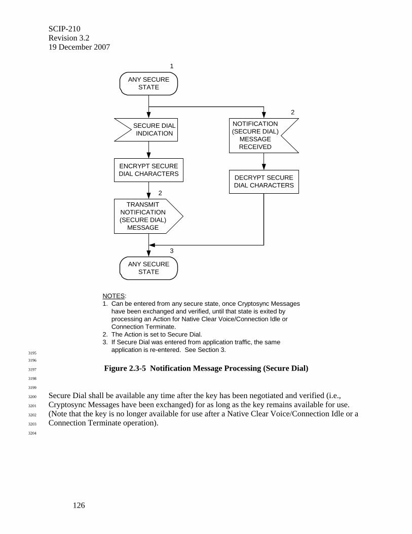
SCIP-210 Revision 3.2 19 December 2007
126
NOTES:1. Can be entered from any secure state, once Cryptosync Messages have been exchanged and verified, until that state is exited by processing an Action for Native Clear Voice/Connection Idle or Connection Terminate.2. The Action is set to Secure Dial.3. If Secure Dial was entered from application traffic, the same application is re-entered. See Section 3.
NOTIFICATION(SECURE DIAL)
MESSAGERECEIVED
2
ANY SECURESTATE
1
TRANSMITNOTIFICATION(SECURE DIAL)
MESSAGE
2
3
ANY SECURESTATE
ENCRYPT SECUREDIAL CHARACTERS
SECURE DIALINDICATION
DECRYPT SECUREDIAL CHARACTERS
3195
3196
Figure 2.3-5 Notification Message Processing (Secure Dial) 3197
3198
3199
Secure Dial shall be available any time after the key has been negotiated and verified (i.e., 3200
Cryptosync Messages have been exchanged) for as long as the key remains available for use. 3201
(Note that the key is no longer available for use after a Native Clear Voice/Connection Idle or a 3202
Connection Terminate operation). 3203
3204
SCIP-210 Revision 3.2
19 December 2007
127
3205
2.3.2.5.1 Encryption of Secure Dial Characters 3206
3207
The encryption of Secure Dial characters is specified in SCIP-230 or SCIP-231, Section 4.1.3.1; 3208
or SCIP-232, Section 4.3.1. The Secure MELP Voice encryption mode is used. In this mode 3209
two 54 bit frames are encrypted for each value of the state vector (which in Secure Dial is based 3210
on the value carried in the IV field of the Notification Message). The Secure Dial characters are 3211
ordered as they will be displayed or passed to the red gateway (e.g., character 1 in the message is 3212
to be displayed before character 2, etc.). 3213
3214
The Secure Dial characters to be included in a Notification Message shall be formatted into one 3215
or two six-character frames prior to encryption. If there are fewer than six characters in a frame, 3216
padding may be used to complete the frame. While the IV is updated for each Notification 3217
Message sent, for a single Notification Message both frames shall be encrypted, as specified in 3218
SCIP-230 or SCIP-231, Section 4.1.3.1; or SCIP-232, Section 4.3.1, using the same IV. 3219
3220
After the data has been encrypted, it is transmitted in the Information Text field of a Notification 3221
Message. Only the encrypted bits corresponding to the Secure Dial characters shall be 3222
transmitted. Encrypted padding octets (if present) shall be discarded. 3223
3224
3225
2.3.2.5.2 Data Transmission and Reception 3226
3227
The terminal shall format a Notification Message as shown in Table 2.3-1, with the Action set to 3228
Secure Dial and the Information Text formatted as shown in Table 2.3-7, and transmit it to the 3229
far-end terminal. If the Secure Dial transmission interrupted full bandwidth application traffic, 3230
after the Notification Message has been acknowledged the terminal will re-enter the same 3231
application using the signaling specified in Section 3.2. 3232
3233
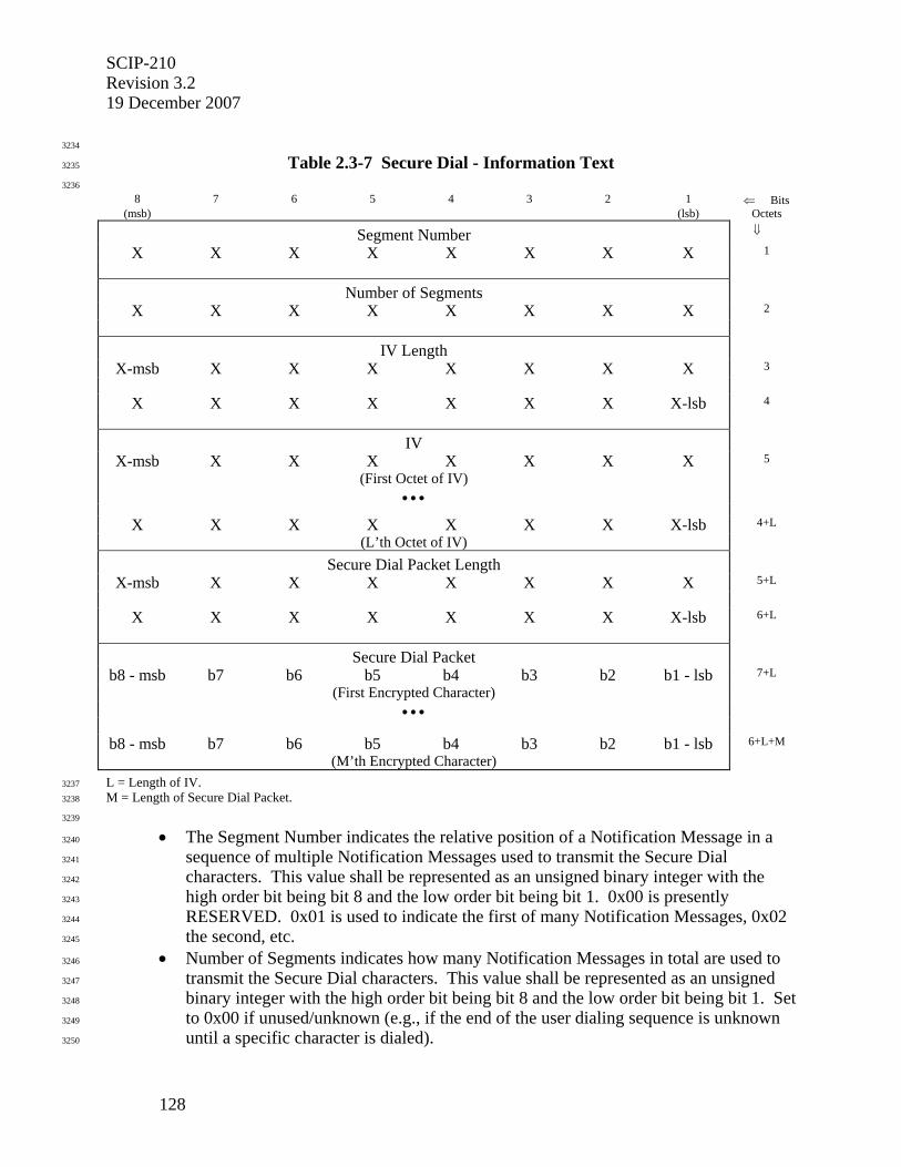
SCIP-210 Revision 3.2 19 December 2007
128
3234
Table 2.3-7 Secure Dial - Information Text 3235
3236
8 7 6 5 4 3 2 1 ⇐ Bits (msb) (lsb) Octets
Segment Number ⇓
X X X X X X X X 1
Number of Segments
X X X X X X X X 2
IV Length
X-msb X X X X X X X 3
X X X X X X X X-lsb 4
IV
X-msb X X X X X X X 5
(First Octet of IV)
• • •
X X X X X X X X-lsb 4+L
(L’th Octet of IV)
Secure Dial Packet Length
X-msb X X X X X X X 5+L
X X X X X X X X-lsb 6+L
Secure Dial Packet
b8 - msb b7 b6 b5 b4 b3 b2 b1 - lsb 7+L
(First Encrypted Character)
• • •
b8 - msb b7 b6 b5 b4 b3 b2 b1 - lsb 6+L+M
(M’th Encrypted Character)
L = Length of IV. 3237
M = Length of Secure Dial Packet. 3238
3239
• The Segment Number indicates the relative position of a Notification Message in a 3240
sequence of multiple Notification Messages used to transmit the Secure Dial 3241
characters. This value shall be represented as an unsigned binary integer with the 3242
high order bit being bit 8 and the low order bit being bit 1. 0x00 is presently 3243
RESERVED. 0x01 is used to indicate the first of many Notification Messages, 0x02 3244
the second, etc. 3245
• Number of Segments indicates how many Notification Messages in total are used to 3246
transmit the Secure Dial characters. This value shall be represented as an unsigned 3247
binary integer with the high order bit being bit 8 and the low order bit being bit 1. Set 3248
to 0x00 if unused/unknown (e.g., if the end of the user dialing sequence is unknown 3249
until a specific character is dialed). 3250
SCIP-210 Revision 3.2
19 December 2007
129
• The IV Length field contains the actual length of the IV field (plus the IV Length 3251
field itself) in octets. The value of the field shall be an unsigned binary integer with 3252
the high order bit being bit 8 of octet 3 and the low order bit being bit 1 of octet 4. 3253
• The IV field shall contain the IV used to encrypt the Secure Dial Characters. Details 3254
of the length, format, and contents are found in SCIP-230, Section 3.5.1, SCIP-231, 3255
Section 3.3.1, or SCIP-232, Section 3.6.1. The msb of the IV (as defined in SCIP-3256
23x) is placed in bit 8 of octet 5. 3257
• Secure Dial Packet Length field contains the actual length of the Secure Dial Packet 3258
(plus the Secure Dial Packet Length field itself) in octets. The high order bit of the 3259
Secure Dial Packet Length is placed in bit 8 of the first octet of the field and the low 3260
order bit is placed in the second octet of the field. 3261
• Secure Dial Packet. Contains one to twelve encrypted Secure Dial Characters. 3262
3263
Upon receipt of a Notification Message with the Action set to Secure Dial, the terminal shall 3264
decrypt the Secure Dial characters and make them available either for display or for use in 3265
controlling a red gateway. If the Secure Dial transmission interrupted full bandwidth application 3266
traffic, after the Notification Message has been correctly received and acknowledged the 3267
terminal will re-enter the same application using the signaling specified in Section 3.2. 3268
3269
Editor’s Note: If additional secure Notifications are added to the Signaling Plan, the intent is to follow the general structure shown in Table 2.3-7, i.e., the Information Text field will carry an IV followed by encrypted data.
3270
3271
2.3.2.6 Notification (Attention) 3272
3273
Editor’s Note: Implementation of Attention is optional. This means that a terminal does not have to implement the capability to transmit it nor to process it (i.e., alerting the user). However, a terminal receiving an Attention is required to acknowledge it in the same manner as with all other standard SCIP messages. If it is implemented, terminals with this capability will behave in accordance to the specifications outlined in this section.
3274
Attention shall be available from any state during a call except when the terminal is already 3275
processing a Native Clear Voice/Connection Idle or Connection Terminate. It is invoked when a 3276
terminal receives a local indication to send an Attention to the far end. When received, the 3277
Notification Message (containing the Attention option) alerts the terminal to warn the user by 3278
performing a vendor elected action (e.g., emitting an audible tone, blinking the display, etc.). 3279
This processing is shown in Figure 2.3-6. 3280
3281
Upon receipt of an Attention indication, the terminal shall format a Notification Message as 3282
specified in Table 2.3-1, with the Action set to Attention, and transmit it to the far-end terminal. 3283
If the entry to Attention processing was from an application, the terminal shall re-enter the same 3284
application via processing as specified in the subsection of Section 3 that describes that 3285
application. 3286
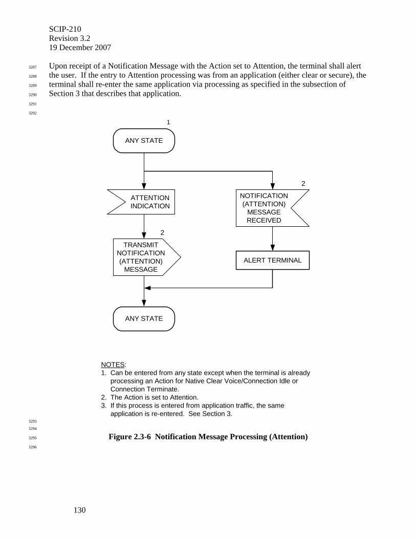
SCIP-210 Revision 3.2 19 December 2007
130
Upon receipt of a Notification Message with the Action set to Attention, the terminal shall alert 3287
the user. If the entry to Attention processing was from an application (either clear or secure), the 3288
terminal shall re-enter the same application via processing as specified in the subsection of 3289
Section 3 that describes that application. 3290
3291
3292
NOTES:1. Can be entered from any state except when the terminal is already processing an Action for Native Clear Voice/Connection Idle or Connection Terminate.2. The Action is set to Attention.3. If this process is entered from application traffic, the same application is re-entered. See Section 3.
ATTENTIONINDICATION
ANY STATE
1
2
2
TRANSMITNOTIFICATION(ATTENTION)
MESSAGEALERT TERMINAL
NOTIFICATION(ATTENTION)
MESSAGERECEIVED
ANY STATE
3293
3294
Figure 2.3-6 Notification Message Processing (Attention) 3295
3296
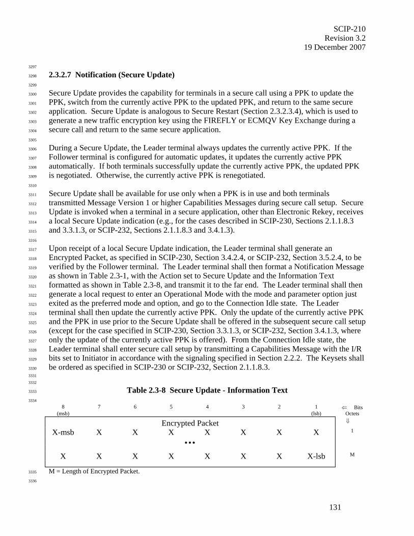
SCIP-210 Revision 3.2
19 December 2007
131
3297
2.3.2.7 Notification (Secure Update) 3298
3299
Secure Update provides the capability for terminals in a secure call using a PPK to update the 3300
PPK, switch from the currently active PPK to the updated PPK, and return to the same secure 3301
application. Secure Update is analogous to Secure Restart (Section 2.3.2.3.4), which is used to 3302
generate a new traffic encryption key using the FIREFLY or ECMQV Key Exchange during a 3303
secure call and return to the same secure application. 3304
3305
During a Secure Update, the Leader terminal always updates the currently active PPK. If the 3306
Follower terminal is configured for automatic updates, it updates the currently active PPK 3307
automatically. If both terminals successfully update the currently active PPK, the updated PPK 3308
is negotiated. Otherwise, the currently active PPK is renegotiated. 3309
3310
Secure Update shall be available for use only when a PPK is in use and both terminals 3311
transmitted Message Version 1 or higher Capabilities Messages during secure call setup. Secure 3312
Update is invoked when a terminal in a secure application, other than Electronic Rekey, receives 3313
a local Secure Update indication (e.g., for the cases described in SCIP-230, Sections 2.1.1.8.3 3314
and 3.3.1.3, or SCIP-232, Sections 2.1.1.8.3 and 3.4.1.3). 3315
3316
Upon receipt of a local Secure Update indication, the Leader terminal shall generate an 3317
Encrypted Packet, as specified in SCIP-230, Section 3.4.2.4, or SCIP-232, Section 3.5.2.4, to be 3318
verified by the Follower terminal. The Leader terminal shall then format a Notification Message 3319
as shown in Table 2.3-1, with the Action set to Secure Update and the Information Text 3320
formatted as shown in Table 2.3-8, and transmit it to the far end. The Leader terminal shall then 3321
generate a local request to enter an Operational Mode with the mode and parameter option just 3322
exited as the preferred mode and option, and go to the Connection Idle state. The Leader 3323
terminal shall then update the currently active PPK. Only the update of the currently active PPK 3324
and the PPK in use prior to the Secure Update shall be offered in the subsequent secure call setup 3325
(except for the case specified in SCIP-230, Section 3.3.1.3, or SCIP-232, Section 3.4.1.3, where 3326
only the update of the currently active PPK is offered). From the Connection Idle state, the 3327
Leader terminal shall enter secure call setup by transmitting a Capabilities Message with the I/R 3328
bits set to Initiator in accordance with the signaling specified in Section 2.2.2. The Keysets shall 3329
be ordered as specified in SCIP-230 or SCIP-232, Section 2.1.1.8.3. 3330
3331
3332
Table 2.3-8 Secure Update - Information Text 3333
3334
8 7 6 5 4 3 2 1 ⇐ Bits (msb) (lsb) Octets
Encrypted Packet ⇓
X-msb X X X X X X X 1
• • •
X X X X X X X X-lsb M
M = Length of Encrypted Packet. 3335
3336
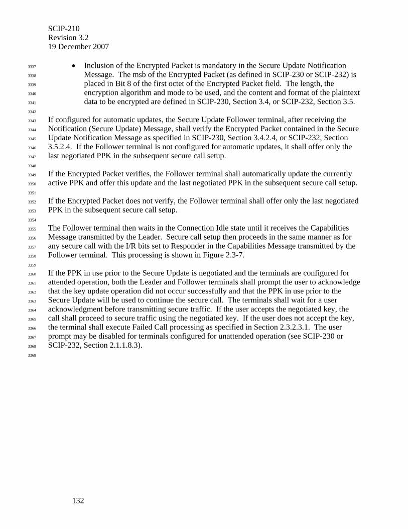
SCIP-210 Revision 3.2 19 December 2007
132
• Inclusion of the Encrypted Packet is mandatory in the Secure Update Notification 3337
Message. The msb of the Encrypted Packet (as defined in SCIP-230 or SCIP-232) is 3338
placed in Bit 8 of the first octet of the Encrypted Packet field. The length, the 3339
encryption algorithm and mode to be used, and the content and format of the plaintext 3340
data to be encrypted are defined in SCIP-230, Section 3.4, or SCIP-232, Section 3.5. 3341
3342
If configured for automatic updates, the Secure Update Follower terminal, after receiving the 3343
Notification (Secure Update) Message, shall verify the Encrypted Packet contained in the Secure 3344
Update Notification Message as specified in SCIP-230, Section 3.4.2.4, or SCIP-232, Section 3345
3.5.2.4. If the Follower terminal is not configured for automatic updates, it shall offer only the 3346
last negotiated PPK in the subsequent secure call setup. 3347
3348
If the Encrypted Packet verifies, the Follower terminal shall automatically update the currently 3349
active PPK and offer this update and the last negotiated PPK in the subsequent secure call setup. 3350
3351
If the Encrypted Packet does not verify, the Follower terminal shall offer only the last negotiated 3352
PPK in the subsequent secure call setup. 3353
3354
The Follower terminal then waits in the Connection Idle state until it receives the Capabilities 3355
Message transmitted by the Leader. Secure call setup then proceeds in the same manner as for 3356
any secure call with the I/R bits set to Responder in the Capabilities Message transmitted by the 3357
Follower terminal. This processing is shown in Figure 2.3-7. 3358
3359
If the PPK in use prior to the Secure Update is negotiated and the terminals are configured for 3360
attended operation, both the Leader and Follower terminals shall prompt the user to acknowledge 3361
that the key update operation did not occur successfully and that the PPK in use prior to the 3362
Secure Update will be used to continue the secure call. The terminals shall wait for a user 3363
acknowledgment before transmitting secure traffic. If the user accepts the negotiated key, the 3364
call shall proceed to secure traffic using the negotiated key. If the user does not accept the key, 3365
the terminal shall execute Failed Call processing as specified in Section 2.3.2.3.1. The user 3366
prompt may be disabled for terminals configured for unattended operation (see SCIP-230 or 3367
SCIP-232, Section 2.1.1.8.3). 3368
3369
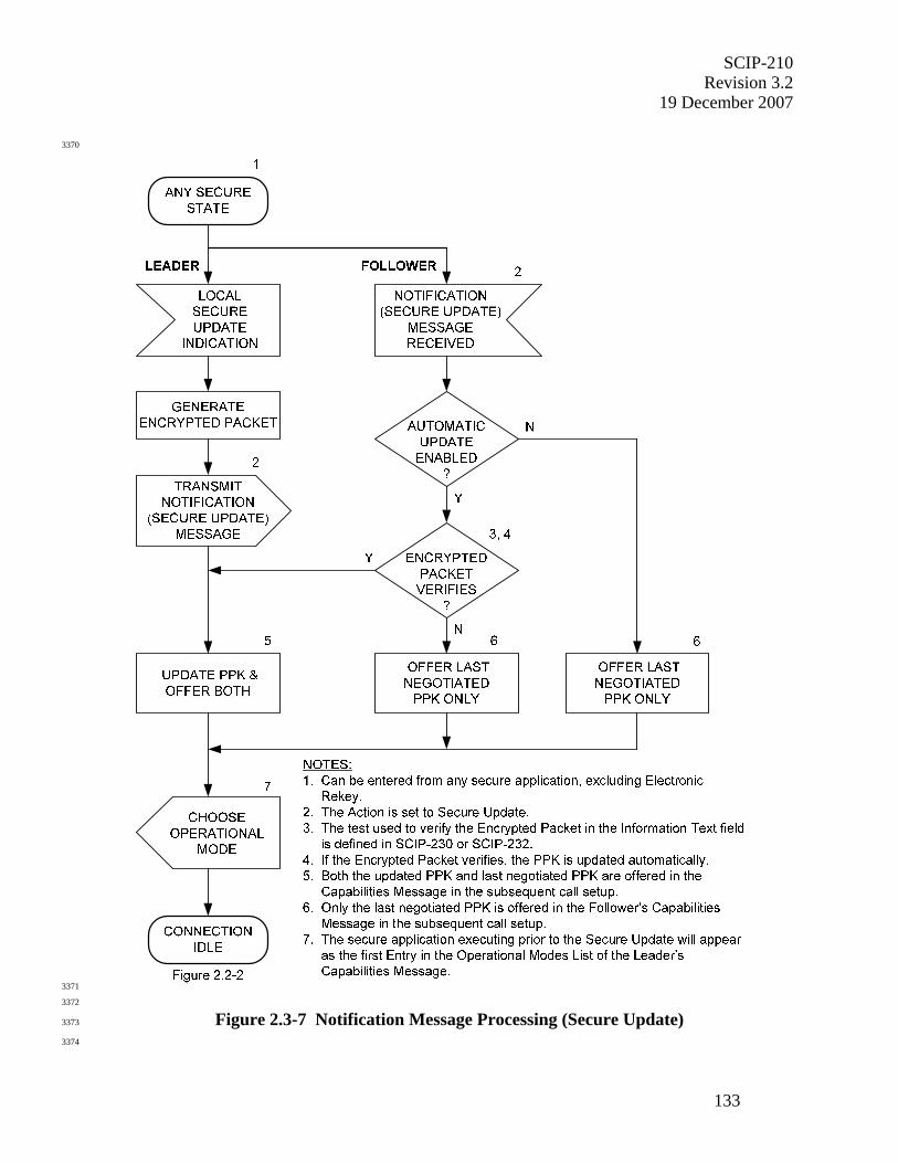
SCIP-210 Revision 3.2
19 December 2007
133
3370
3371
3372
Figure 2.3-7 Notification Message Processing (Secure Update) 3373
3374

SCIP-210 Revision 3.2 19 December 2007
134
3375
2.3.3 Mode Change Processing 3376
3377
This section specifies the signaling associated with Mode Change processing. Mode Change 3378
processing shall be available for use only when both terminals transmitted Message Version 1 or 3379
higher Capabilities Messages during SCIP secure call setup, and will be entered only when both 3380
terminals are in secure application traffic. The use of Mode Change shall be limited to changing 3381
from one secure application to a different secure application, or to the same secure application 3382
with different parameters, using the same key and the same traffic encryption algorithm. Two 3383
messages are involved: Mode Change Request and Mode Change Response. Section 2.3.3.1 3384
specifies the Mode Change Request Message, and Section 2.3.3.2 specifies the Mode Change 3385
Response Message. The signaling is shown in Figure 2.3-8. 3386
3387
Editor’s Note: Currently, the only standard SCIP clear application defined is Clear MELP Voice. In the event that other standard SCIP clear applications are defined, Mode Change may need to be updated to include changing from one clear application to another one.
3388
3389
2.3.3.1 Mode Change Request Message 3390
3391
Mode Change is invoked when a terminal in a secure application receives a local Mode Change 3392
indication. The terminal will ensure that the requested Operational Mode is one common to both 3393
terminals and that it is allowed by the ACL, if the ACL has been activated for the chosen 3394
Operational Mode (See SCIP-230 or SCIP-232, Section 2.1.3.1.2) and the chosen Keyset Type is 3395
supported by the ACL, before proceeding. If the ACL has not been activated for the chosen 3396
Operational Mode and/or the chosen Keyset Type is not supported by the ACL, the ACL check 3397
is skipped. Upon receipt of a local Mode Change indication, the terminal shall assume the role 3398
of Leader, format a Mode Change Request Message, and transmit it to the far end. The format of 3399
the Mode Change Request Message shall be as specified in Table 2.3-9. The Leader shall then 3400
wait for a Mode Change Response Message from the far-end terminal. 3401
3402
Upon receipt of a Mode Change Response Message, the Leader shall format a Cryptosync 3403
Message as specified in Section 2.2.5, transmit it to the far-end terminal, and wait for a 3404
Cryptosync Message. Upon receipt of a Cryptosync Message, the terminal shall verify the 3405
Encrypted Packet contained in the Cryptosync Message as specified in SCIP-230, Section 3.4.2, 3406
SCIP-231, Section 3.2.2, or SCIP-232, Section 3.5.2. If this check does not pass, the terminal 3407
shall execute Failed Call processing, defined in Section 2.3.2.3.1, with an Information Code of 3408
sync message verification failure. If the Encrypted Packet check passes and there was no 3409
classification change as a result of the Mode Change, the terminal shall initiate the indicated 3410
Operational Mode as specified in Section 3. If the classification was changed during the Mode 3411
Change, the user shall be prompted, and an acknowledgment is required prior to initiating the 3412
indicated Operational Mode. 3413
3414
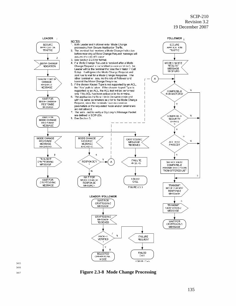
SCIP-210 Revision 3.2
19 December 2007
135
3415
3416
Figure 2.3-8 Mode Change Processing 3417

SCIP-210 Revision 3.2 19 December 2007
136
The following signaling will take place in the event of a race condition, i.e., both terminals 3418
receive local Mode Change indications and transmit Mode Change Request Messages. The 3419
terminal that was determined to be the Responder in call setup shall assume the role of Follower, 3420
and the other terminal shall assume the role of Leader. The Leader, upon receipt of a Mode 3421
Change Request Message, shall ignore it, wait for the Mode Change Response Message, and 3422
continue in the manner described above when it is received. The Follower, upon receipt of a 3423
Mode Change Request Message shall proceed in the manner described in Section 2.3.3.2. 3424
3425
In the event of a glare condition, i.e., instead of receiving the expected Mode Change Response 3426
Message, the Leader receives a Cryptosync Message, the following signaling shall take place. 3427
Upon receipt of the Cryptosync Message, the terminal shall initiate Failed Call processing as 3428
specified in Section 2.3.2.3 with the Information Code set to Cryptosync/Mode Change glare. 3429
3430
3431
Table 2.3-9 Mode Change Request Message Format 3432
3433
8 7 6 5 4 3 2 1 ⇐ Bits (msb) (lsb) Octets
MID ⇓
0-msb 0 0 0 0 0 0 0 1 Source ID
0 0 0 1 1 0 1 0-lsb 2
Message Length
X-msb X X X X X X X 3
X X X X X X X X-lsb 4
Message Version
0 0 0 0 0 0 0 0 5
Operational Mode
X-msb X X X X X X X 6 Source ID
X X X X X X X X-lsb 7
Parameters Length
X-msb X X X X X X X 8
X X X X X X X X-lsb 9
Operational Mode Parameters (Optional)
X X X X X X X X 10
• • • X X X X X X X X 9+L
L = Length of Operational Mode Parameters. 3434

SCIP-210 Revision 3.2
19 December 2007
137
3435
• For the Mode Change Request Message, the value of the MID is 0x001A. 3436
• The Message Length shall contain the actual length of the message body (including 3437
the length of the Message Length field itself but not including the length of the MID 3438
field) in octets. The value of the field shall be an unsigned binary integer with the 3439
high order bit being bit 8 of octet 3 and the low order bit being bit 1 of octet 4. 3440
• For the version of the Mode Change Request Message defined in this version of the 3441
Signaling Plan, the value of the Message Version field is 0x00. 3442
• The Operational Mode field shall contain the ID of the selected Operational Mode. 3443
For the format and values of these IDs, see the definition of Operational Mode IDs in 3444
Section 2.2.2.1. The high order bit of the Operational Mode field is placed in bit 8 of 3445
octet 6 and the low order bit is placed in bit 1 of octet 7. Note that this selected 3446
Operational Mode will be one supported by both terminals. 3447
• The Parameters Length field contains the actual length of the Operational Mode 3448
Parameters field (plus the length of the Parameters Length itself), in octets. The 3449
value of the field shall be an unsigned binary integer with the high order bit being bit 3450
8 of the first octet of the field and the low order bit being bit 1 of the second octet of 3451
the field. 3452
• The Operational Mode Parameters field shall contain parameters for the selected 3453
Operational Mode. The length, format, and contents of the Operational Mode 3454
Parameters are unique to each Operational Mode and are defined in Section 2.2.6 for 3455
each standard Operational Mode having a Parameters/Certificate Exchange. This 3456
field is optional and is not present unless Parameters are defined for a given 3457
Operational Mode. 3458
3459
3460
2.3.3.2 Mode Change Response Message 3461
3462
Upon receipt of a Mode Change Request Message while in a secure application, the terminal 3463
shall assume the role of Follower. It shall then check for compatible parameters and security 3464
levels for the offered Operational Mode. If the ACL has been activated for the chosen 3465
Operational Mode and the chosen Keyset Type is supported by the ACL, the terminal shall also 3466
perform the ACL test as specified in SCIP-230 or SCIP-232, Section 2.1.3.1.2. If there are 3467
compatible parameters and compatible security levels and the ACL test passes, the Follower 3468
shall accept the offered Operational Mode. If there are no compatible parameters or no 3469
compatible security levels, or if the ACL test fails, the terminals shall continue executing the 3470
current Operational Mode. If the ACL has not been activated for the chosen Operational Mode 3471
and/or the chosen Keyset Type is not supported by the ACL, the ACL check is skipped. 3472
3473
The Follower shall transmit to the far end a Mode Change Response Message formatted as 3474
specified in Table 2.3-10 indicating the selected Operational Mode and Operational Mode 3475
Parameters Option. It shall then format a Cryptosync Message as specified in Section 2.2.5, 3476
transmit it to the far-end terminal, and wait for a Cryptosync Message. Upon receipt of a 3477
Cryptosync Message, the terminal shall verify the Encrypted Packet contained in the Cryptosync 3478
Message as specified in SCIP-230, Section 3.4.2.3, SCIP-231, Section 3.2.2, or SCIP-232, 3479
Section 3.5.2.3. If this check does not pass, the terminal shall execute Failed Call processing, 3480
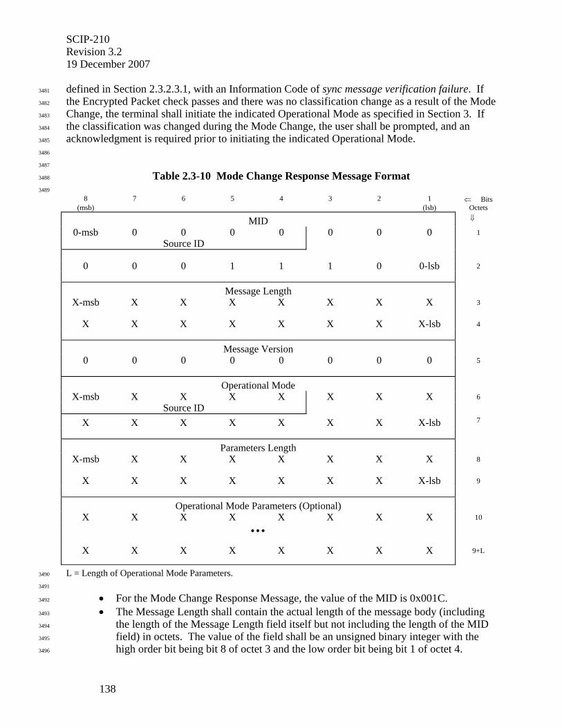
SCIP-210 Revision 3.2 19 December 2007
138
defined in Section 2.3.2.3.1, with an Information Code of sync message verification failure. If 3481
the Encrypted Packet check passes and there was no classification change as a result of the Mode 3482
Change, the terminal shall initiate the indicated Operational Mode as specified in Section 3. If 3483
the classification was changed during the Mode Change, the user shall be prompted, and an 3484
acknowledgment is required prior to initiating the indicated Operational Mode. 3485
3486
3487
Table 2.3-10 Mode Change Response Message Format 3488
3489
8 7 6 5 4 3 2 1 ⇐ Bits (msb) (lsb) Octets
MID ⇓
0-msb 0 0 0 0 0 0 0 1 Source ID
0 0 0 1 1 1 0 0-lsb 2
Message Length
X-msb X X X X X X X 3
X X X X X X X X-lsb 4
Message Version
0 0 0 0 0 0 0 0 5
Operational Mode
X-msb X X X X X X X 6 Source ID
X X X X X X X X-lsb 7
Parameters Length
X-msb X X X X X X X 8
X X X X X X X X-lsb 9
Operational Mode Parameters (Optional)
X X X X X X X X 10
• • •
X X X X X X X X 9+L
L = Length of Operational Mode Parameters. 3490
3491
• For the Mode Change Response Message, the value of the MID is 0x001C. 3492
• The Message Length shall contain the actual length of the message body (including 3493
the length of the Message Length field itself but not including the length of the MID 3494
field) in octets. The value of the field shall be an unsigned binary integer with the 3495
high order bit being bit 8 of octet 3 and the low order bit being bit 1 of octet 4. 3496

SCIP-210 Revision 3.2
19 December 2007
139
• For the version of the Mode Change Response Message defined in this version of the 3497
Signaling Plan, the value of the Message Version field is 0x00. 3498
• The Operational Mode field shall contain the ID of the selected Operational Mode. 3499
For the format and values of these IDs, see the definition of Operational Mode IDs in 3500
Section 2.2.2.1. The high order bit of the Operational Mode field is placed in bit 8 of 3501
octet 6, and the low order bit is placed in bit 1 of octet 7. Note that Operational Mode 3502
shall be the mode offered in the Mode Change Request Message, unless either the 3503
terminal cannot support at least one of the offered Operational Mode Parameters 3504
Options, if included, or the ACL test fails. If the terminal does not support any of the 3505
Options offered or if the ACL test fails, the Operational Mode shall be the mode the 3506
terminal was executing when the Mode Change Request Message was received. 3507
• The Parameters Length field contains the actual length of the Operational Mode 3508
Parameters field (plus the length of the Parameters Length field itself), in octets. The 3509
value of the field shall be an unsigned binary integer with the high order bit being bit 3510
8 of the first octet of the field and the low order bit being bit 1 of the second octet of 3511
the field. 3512
• The Operational Mode Parameters shall contain the first Option on the Leader’s 3513
Options List that is also supported by the Follower for the selected Operational Mode. 3514
The length, format, and contents of the Operational Mode Parameters are unique to 3515
each Operational Mode and are defined in Section 2.2.6 for each standard Operational 3516
Mode having a Parameters/Certificate Exchange. This field is optional and is not 3517
present unless Parameters are defined for the selected Operational Mode. If the 3518
terminal does not support any of the Options offered or if the ACL test fails, the 3519
Operational Mode Parameters shall contain the Option the terminal was executing 3520
when the Mode Change Request Message was received. 3521
3522
3523
2.3.4 Two-Way Resync Processing 3524
3525
This section specifies the signaling associated with Two-Way Resync processing. Only the 3526
Cryptosync Message is involved. The processing is shown in Figure 2.3-9. Two-Way Resync 3527
processing is invoked when a terminal in secure application traffic receives a local Two-Way 3528
Resync indication. A local Two-Way Resync indication is generated when a terminal detects 3529
that it has lost cryptographic synchronization with the far end or when selected manually by the 3530
user (e.g., by selecting "Secure" during secure application traffic). 3531
3532
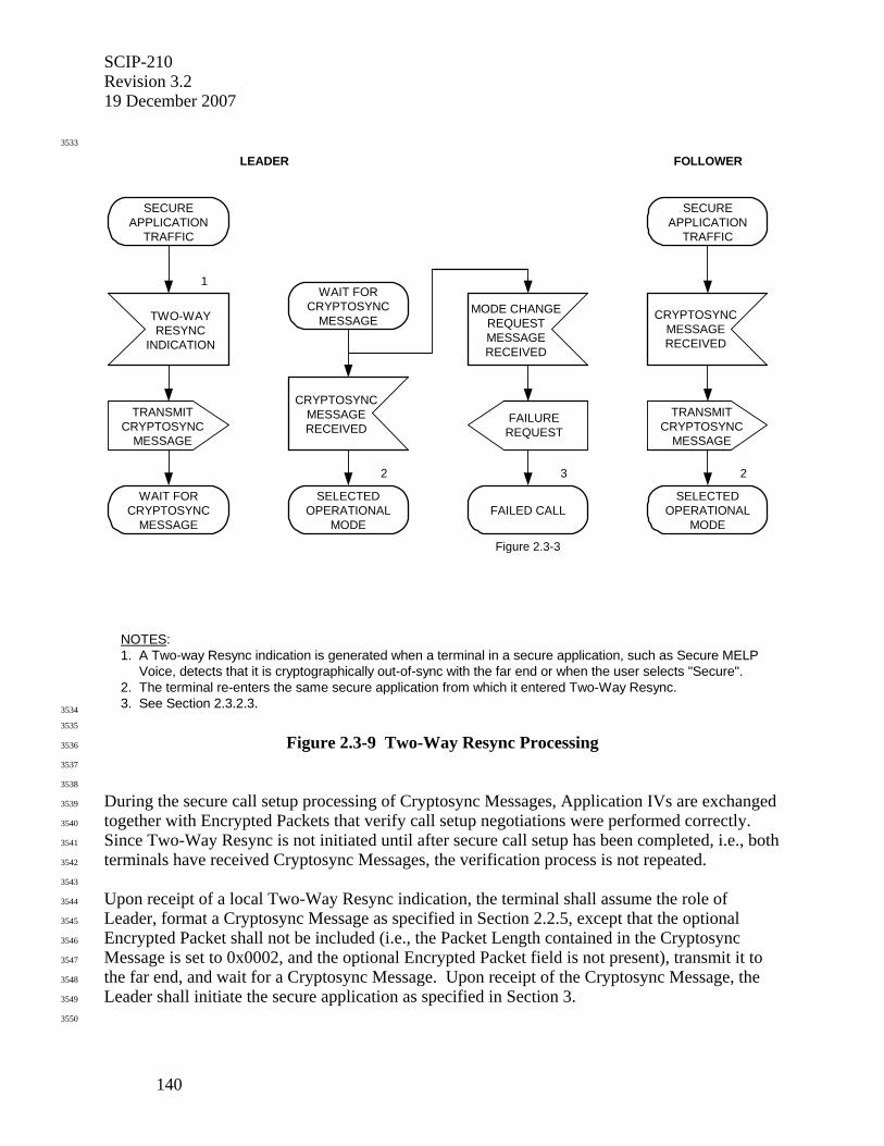
SCIP-210 Revision 3.2 19 December 2007
140
3533
NOTES:1. A Two-way Resync indication is generated when a terminal in a secure application, such as Secure MELP Voice, detects that it is cryptographically out-of-sync with the far end or when the user selects "Secure".2. The terminal re-enters the same secure application from which it entered Two-Way Resync.3. See Section 2.3.2.3.
LEADER
FAILUREREQUEST
FAILED CALL
3
TRANSMITCRYPTOSYNC
MESSAGE
WAIT FORCRYPTOSYNC
MESSAGE
MODE CHANGEREQUESTMESSAGERECEIVED
1
TWO-WAYRESYNC
INDICATION
SECUREAPPLICATION
TRAFFIC
Figure 2.3-3
SECUREAPPLICATION
TRAFFIC
CRYPTOSYNCMESSAGERECEIVED
FOLLOWER
SELECTEDOPERATIONAL
MODE
2
TRANSMITCRYPTOSYNC
MESSAGE
CRYPTOSYNCMESSAGERECEIVED
SELECTEDOPERATIONAL
MODE
2
WAIT FORCRYPTOSYNC
MESSAGE
3534
3535
Figure 2.3-9 Two-Way Resync Processing 3536
3537
3538
During the secure call setup processing of Cryptosync Messages, Application IVs are exchanged 3539
together with Encrypted Packets that verify call setup negotiations were performed correctly. 3540
Since Two-Way Resync is not initiated until after secure call setup has been completed, i.e., both 3541
terminals have received Cryptosync Messages, the verification process is not repeated. 3542
3543
Upon receipt of a local Two-Way Resync indication, the terminal shall assume the role of 3544
Leader, format a Cryptosync Message as specified in Section 2.2.5, except that the optional 3545
Encrypted Packet shall not be included (i.e., the Packet Length contained in the Cryptosync 3546
Message is set to 0x0002, and the optional Encrypted Packet field is not present), transmit it to 3547
the far end, and wait for a Cryptosync Message. Upon receipt of the Cryptosync Message, the 3548
Leader shall initiate the secure application as specified in Section 3. 3549
3550
SCIP-210 Revision 3.2
19 December 2007
141
Upon receipt of a Cryptosync Message, a terminal that has not transmitted a Cryptosync 3551
Message shall assume the role of Follower, format a Cryptosync Message as specified in Section 3552
2.2.5 (but without the optional Encrypted Packet), transmit it to the far-end terminal, and initiate 3553
the secure application as specified in Section 3. 3554
3555
In the event of a glare condition, i.e., instead of receiving the expected Cryptosync Message, the 3556
Leader receives a Mode Change Request Message, the following signaling shall take place. 3557
Upon receipt of the Mode Change Request Message, the terminal shall initiate Failed Call 3558
processing as specified in Section 2.3.2.3 with the Information Code set to Cryptosync/Mode 3559
Change glare. 3560
3561
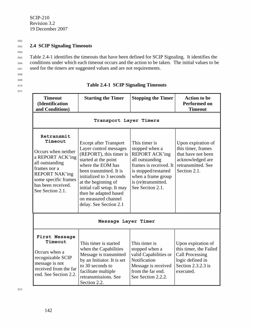
SCIP-210 Revision 3.2 19 December 2007
142
3562
2.4 SCIP Signaling Timeouts 3563
3564
Table 2.4-1 identifies the timeouts that have been defined for SCIP Signaling. It identifies the 3565
conditions under which each timeout occurs and the action to be taken. The initial values to be 3566
used for the timers are suggested values and are not requirements. 3567
3568
3569
Table 2.4-1 SCIP Signaling Timeouts 3570
3571
Timeout (Identification
and Conditions)
Starting the Timer Stopping the Timer Action to be Performed on
Timeout
Transport Layer Timers
Retransmit Timeout
Occurs when neither a REPORT ACK’ing all outstanding frames nor a REPORT NAK’ing some specific frames has been received. See Section 2.1.
Except after Transport Layer control messages (REPORT), this timer is started at the point where the EOM has been transmitted. It is initialized to 3 seconds at the beginning of initial call setup. It may then be adapted based on measured channel delay. See Section 2.1
This timer is stopped when a REPORT ACK’ing all outstanding frames is received. It is stopped/restarted when a frame group is (re)transmitted. See Section 2.1.
Upon expiration of this timer, frames that have not been acknowledged are retransmitted. See Section 2.1.
Message Layer Timer
First Message
Timeout Occurs when a recognizable SCIP message is not received from the far end. See Section 2.2.
This timer is started when the Capabilities Message is transmitted by an Initiator. It is set to 30 seconds to facilitate multiple retransmissions. See Section 2.2.
This timer is stopped when a valid Capabilities or Notification Message is received from the far end. See Section 2.2.2.
Upon expiration of this timer, the Failed Call Processing logic defined in Section 2.3.2.3 is executed.
3572
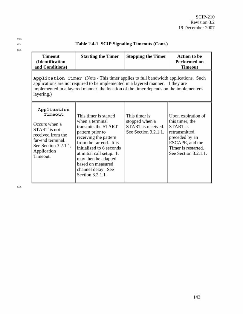
SCIP-210 Revision 3.2
19 December 2007
143
3573
Table 2.4-1 SCIP Signaling Timeouts (Cont.) 3574
3575
Timeout (Identification
and Conditions)
Starting the Timer Stopping the Timer Action to be Performed on
Timeout Application Timer (Note - This timer applies to full bandwidth applications. Such applications are not required to be implemented in a layered manner. If they are implemented in a layered manner, the location of the timer depends on the implementer's layering.) Application
Timeout Occurs when a START is not received from the far-end terminal. See Section 3.2.1.1, Application Timeout.
This timer is started when a terminal transmits the START pattern prior to receiving the pattern from the far end. It is initialized to 6 seconds at initial call setup. It may then be adapted based on measured channel delay. See Section 3.2.1.1.
This timer is stopped when a START is received. See Section 3.2.1.1.
Upon expiration of this timer, the START is retransmitted, preceded by an ESCAPE, and the Timer is restarted. See Section 3.2.1.1.
3576
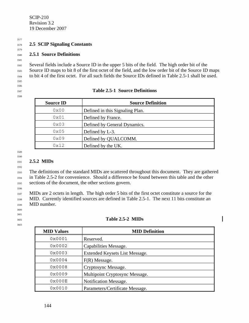
SCIP-210 Revision 3.2 19 December 2007
144
3577
2.5 SCIP Signaling Constants 3578
3579
2.5.1 Source Definitions 3580
3581
Several fields include a Source ID in the upper 5 bits of the field. The high order bit of the 3582
Source ID maps to bit 8 of the first octet of the field, and the low order bit of the Source ID maps 3583
to bit 4 of the first octet. For all such fields the Source IDs defined in Table 2.5-1 shall be used. 3584
3585
3586
Table 2.5-1 Source Definitions 3587
3588
Source ID Source Definition 0x00 Defined in this Signaling Plan. 0x01 Defined by France. 0x03 Defined by General Dynamics. 0x05 Defined by L-3. 0x09 Defined by QUALCOMM. 0x12 Defined by the UK.
3589
3590
2.5.2 MIDs 3591
3592
The definitions of the standard MIDs are scattered throughout this document. They are gathered 3593
in Table 2.5-2 for convenience. Should a difference be found between this table and the other 3594
sections of the document, the other sections govern. 3595
3596
MIDs are 2 octets in length. The high order 5 bits of the first octet constitute a source for the 3597
MID. Currently identified sources are defined in Table 2.5-1. The next 11 bits constitute an 3598
MID number. 3599
3600
3601
Table 2.5-2 MIDs 3602
3603
MID Values MID Definition 0x0001 Reserved. 0x0002 Capabilities Message. 0x0003 Extended Keysets List Message. 0x0004 F(R) Message. 0x0008 Cryptosync Message. 0x0009 Multipoint Cryptosync Message. 0x000E Notification Message. 0x0010 Parameters/Certificate Message.

SCIP-210 Revision 3.2
19 December 2007
145
3604
Table 2.5-2 MIDs (Cont.) 3605
3606
MID Values MID Definition 0x001A Mode Change Request Message. 0x001C Mode Change Response Message. 0x0020 REPORT. 0x0023 Reserved for Tactical IWF (CONNECT). 0x0025 Reserved for Tactical IWF (DISCONNECT). 0x0040 Secure Reliable Transport Asynchronous Data Message. 0x0080 Reserved for compatibility with legacy terminals. 0x00E0 SCIP Rekey Message.
3607
3608
2.5.3 Miscellaneous SCIP Signaling Constants 3609
3610
Table 2.5-3 identifies the constants that have been defined for SCIP Signaling. It identifies both 3611
the values and uses of each constant. 3612
3613
3614
2.5.3.1 ESCAPE 3615
3616
The ESCAPE sequence consists of two concatenated copies of the output of a 7-stage maximum 3617
length linear sequence generator padded with the first two bits of the sequence to give 256 bits. 3618
The coefficients of the generator polynomial are 203 (octal) 0
1. 3619
3620
3621
2.5.3.2 Start of Message (SOM) and End of Message (EOM) 3622
3623
The SOM sequence is the output of a 6-stage maximum length linear sequence generator 3624
augmented with a leading zero-bit. The coefficients of the generator polynomial are 103 (octal). 3625
The EOM is the bit by bit complement of the SOM. 3626
3627
3628
2.5.3.3 START and FILLER 3629
3630
The START sequence is the output of a 6-stage maximum length linear sequence generator 3631
augmented with a leading zero-bit. The coefficients of the generator polynomial are 141 (octal). 3632
FILLER is the bit by bit complement of the START sequence. 3633
3634
1 The polynomial with coefficients 203 (octal) is x7 + x + 1.

SCIP-210 Revision 3.2 19 December 2007
146
3635
2.5.3.4 Headers 3636
3637
The Header sequences are the outputs of 4-stage maximum length linear sequence generators, 3638
each augmented with a leading zero-bit. The coefficients of the generator polynomials are 31 3639
(octal) for the Sync Management (SM) frame Header and 23 (octal) for the G.729D Encrypted 3640
Speech (ES) frame Header PN sequence. Note that the ES frame Header PN sequence is formed 3641
by rotating the generator output two bit positions to the right prior to adding the leading zero. 3642
3643
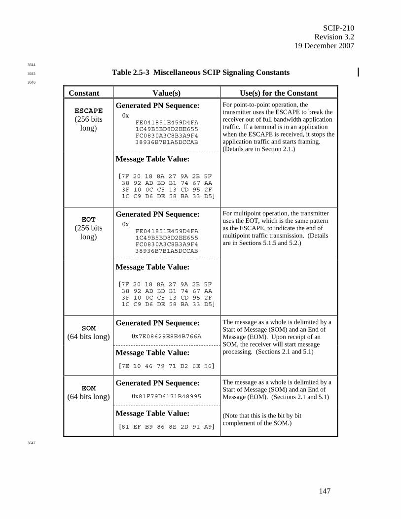
SCIP-210 Revision 3.2
19 December 2007
147
3644
Table 2.5-3 Miscellaneous SCIP Signaling Constants 3645
3646
Constant Value(s) Use(s) for the Constant Generated PN Sequence:
0x FE041851E459D4FA 1C49B5BD8D2EE655 FC0830A3C8B3A9F4 38936B7B1A5DCCAB
ESCAPE (256 bits
long)
Message Table Value:
[7F 20 18 8A 27 9A 2B 5F 38 92 AD BD B1 74 67 AA 3F 10 0C C5 13 CD 95 2F 1C C9 D6 DE 58 BA 33 D5]
For point-to-point operation, the transmitter uses the ESCAPE to break the receiver out of full bandwidth application traffic. If a terminal is in an application when the ESCAPE is received, it stops the application traffic and starts framing. (Details are in Section 2.1.)
Generated PN Sequence: 0x
FE041851E459D4FA 1C49B5BD8D2EE655 FC0830A3C8B3A9F4 38936B7B1A5DCCAB
EOT
(256 bits long)
Message Table Value:
[7F 20 18 8A 27 9A 2B 5F 38 92 AD BD B1 74 67 AA 3F 10 0C C5 13 CD 95 2F 1C C9 D6 DE 58 BA 33 D5]
For multipoint operation, the transmitter uses the EOT, which is the same pattern as the ESCAPE, to indicate the end of multipoint traffic transmission. (Details are in Sections 5.1.5 and 5.2.)
Generated PN Sequence:
0x7E08629E8E4B766A
SOM
(64 bits long)
Message Table Value:
[7E 10 46 79 71 D2 6E 56]
The message as a whole is delimited by a Start of Message (SOM) and an End of Message (EOM). Upon receipt of an SOM, the receiver will start message processing. (Sections 2.1 and 5.1)
Generated PN Sequence:
0x81F79D6171B48995
EOM
(64 bits long)
Message Table Value:
[81 EF B9 86 8E 2D 91 A9]
The message as a whole is delimited by a Start of Message (SOM) and an End of Message (EOM). (Sections 2.1 and 5.1) (Note that this is the bit by bit complement of the SOM.)
3647

SCIP-210 Revision 3.2 19 December 2007
148
3648
Table 2.5-3 Miscellaneous SCIP Signaling Constants (Cont.) 3649
3650
Constant Value(s) Use(s) for the Constant Generated PN Sequence:
0x7EACDDA4E2F28C20
START
(64 bits long)
Message Table Value: [7E 35 BB 25 47 4F 31 04]
Used to detect the start of full bandwidth application traffic. (Sections 3 and 5.1.4)
Generated PN Sequence:
0x7AC8
SM Header (16 bits long)
Message Table Value:
[5E 13]
The first 16 bits of the Sync Management (SM) frame which is sent during full bandwidth application traffic. (Section 3)
Generated PN Sequence:
0x8537
Bit Complement
of SM Header
(16 bits long) Message Table Value:
[A1 EC]
Replaces Header in Sync Management frames containing the first segment of the Partial Long Term Component. (Section 3)
Generated PN Sequence:
0x5E26
ES Header PN Sequence
(16 bits long) Message Table Value:
[7A 64]
The first 16 bits of the G.729D Encrypted Speech frame Header which is sent during Secure G.729D Voice application traffic. (Section 3.3)
Generated PN Sequence:
0x8153225B1D0D73DF
FILLER
(64 bits long)
Message Table Value:
[81 CA 44 DA B8 B0 CE FB]
An integer number of 64-bit pattern repetitions are transmitted following the Cryptosync and Multipoint Cryptosync messages. (Sections 3 and 5.1.3) (Note that this is the bit by bit complement of the START.)
3651
NOTES: 3652
1. The Generated PN Sequence (read left to right and top to bottom if multiple lines) is specified in the bit 3653
order that the PN generator outputs the serial bit stream. 3654
2. The Message Table Value is specified in the bit order that the PN sequences are represented (as octets) in 3655
the message format tables in this document. 3656
3. The Message Table Value is passed, in ascending octet order, to the lower layers for transmission. 3657
SCIP-210 Revision 3.2
19 December 2007
149
3658
3.0 SCIP USER APPLICATION SIGNALING – Point-to-Point Operation 3659
3660
3.1 SCIP User Applications 3661
3662
Six user applications are currently defined for SCIP point-to-point implementations. They are: 3663
1) Secure 2400 bps MELP Voice - Blank and Burst, 2) Secure MELP Voice - Burst w/o Blank, 3664
3) Clear 2400 bps MELP Voice, 4) Secure G.729D Voice - Burst w/o Blank, 5) Secure Reliable 3665
Transport Asynchronous Data, and 6) Secure Best Effort Transport (BET) Asynchronous Data. 3666
[Note that a “reliable message transport” mechanism is also specified for the SCIP Electronic 3667
Rekey application – see Section 4.1.1.] The MELP Voice, Secure G.729D Voice, and Secure 3668
Best Effort Transport Asynchronous Data applications are full-bandwidth applications, since 3669
they are designed for use on connections where the information rate is equal, or approximately 3670
equal, to the available channel rate. Note that any of these applications may be used with a 3671
bearer service, such as IP, where the available transmission bandwidth may considerably exceed 3672
that of the application. It is not required to implement both the voice and data applications in all 3673
terminals. Voice-only and data-only products are allowed. Clear 2400 bps MELP Voice is 3674
optional in all cases. Detailed transmission formats for the SCIP user applications are specified 3675
in Sections 3.3 (voice) and 3.4 (data). The signaling in this Section is shown octet aligned. 3676
However it may be carried on networks that do not preserve octet alignment. Therefore, the 3677
SCIP receiver shall be capable of recovering and processing the SCIP signaling shown herein 3678
even if it is not octet aligned when it is received. 3679
3680
3681
3.2 Application Start-up/Restart Signaling 3682
3683
3.2.1 Full Bandwidth Applications 3684
3685
Full-bandwidth applications (e.g., Secure MELP Voice, Secure G.729D Voice, and Secure Best 3686
Effort Transport Asynchronous Data) are required to bypass the Transport Layer functionality 3687
when they are invoked. This shall be accomplished as specified in the following paragraphs. 3688
3689
There are three cases of full-bandwidth application start-up/restart signaling: the case where a 3690
Cryptosync message exchange has occurred, the case of clear voice start-up, and the case of a 3691
restart following an interruption where only Notification and REPORT messages have been 3692
exchanged. In addition, there is a full bandwidth Application Timeout (specified in Section 3693
3.2.1.1) associated with all three cases. 3694
3695
For start-up/restart after a Cryptosync exchange, a terminal is ready to transition to full 3696
bandwidth application signaling when acknowledgments have been transmitted and received for 3697
all frames of the Cryptosync messages. For this case, the terminal shall transmit an integer 3698
number of repetitions of FILLER not less than 100 milliseconds duration. The START pattern 3699
shall follow FILLER as soon as any frames queued at the Transport Layer are transmitted and, 3700
except for REPORT messages, are acknowledged. For start-up of the Clear MELP Voice 3701
application, a terminal is ready to transition to full bandwidth application signaling when the 3702
final call setup message has been transmitted and acknowledged and the user has enabled 3703
SCIP-210 Revision 3.2 19 December 2007
150
nonsecure operation. For this case, the terminal shall transmit the START pattern, without 3704
FILLER, as soon as any frames queued at the Transport Layer are transmitted and, except for 3705
REPORT messages, are acknowledged. For restart after full bandwidth traffic has been 3706
interrupted by the transmission of a Notification (Secure Dial, or Attention) or a REPORT 3707
message, the START pattern shall be transmitted, without FILLER, as soon as all frames queued 3708
at the Transport Layer are transmitted and, except for REPORT messages, are acknowledged. 3709
3710
Transmission of the START pattern shall be followed by full bandwidth traffic when it is 3711
available. The START pattern shall be transmitted even if no full bandwidth traffic is available 3712
for transmission (because of the Application Timeout – see Section 3.2.1.1). Upon receipt of a 3713
START pattern, a terminal shall begin looking for full bandwidth traffic. The format and length 3714
of FILLER and START patterns are defined in Section 2.5.3. Full bandwidth traffic 3715
transmission formats include Secure MELP Voice (both Blank and Burst and Burst w/o Blank – 3716
Sections 3.3.1.1 and 3.3.1.2, respectively), Clear MELP Voice (Section 3.3.1.3), Secure G.729D 3717
Voice (Section 3.3.2), and Secure Best Effort Transport Asynchronous Data (Section 3.4.2). 3718
3719
Note that start-up/restart applies to secure call setup, Two-Way Resync and Mode Change, and 3720
includes the case where both Cryptosync and Notification Messages are transmitted during a 3721
break in full bandwidth traffic. This case is illustrated in Figure 2.2-1 for secure call setup, in 3722
Figure 2.3-1(d) for Mode Change, and in Figure 2.3-1(e) for Two-Way Resync. Restart after 3723
transmission of a Notification or a REPORT message is illustrated in Figure 2.1-1(c) at the 3724
Transport Layer and in Figure 2.3-1(c) at the Message Layer. 3725
3726
3727
3.2.1.1 Application Timeout 3728
3729
As specified above, a terminal transmits the START pattern when it is ready to start or restart 3730
full bandwidth traffic. An Application Timeout shall be utilized to ensure that both terminals 3731
transition to full bandwidth traffic. A suggested initial value for the Application Timeout is 3732
given in Table 2.4-1. Processing associated with the Application Timeout is shown in Figure 3733
3.2-1. 3734
3735
3736
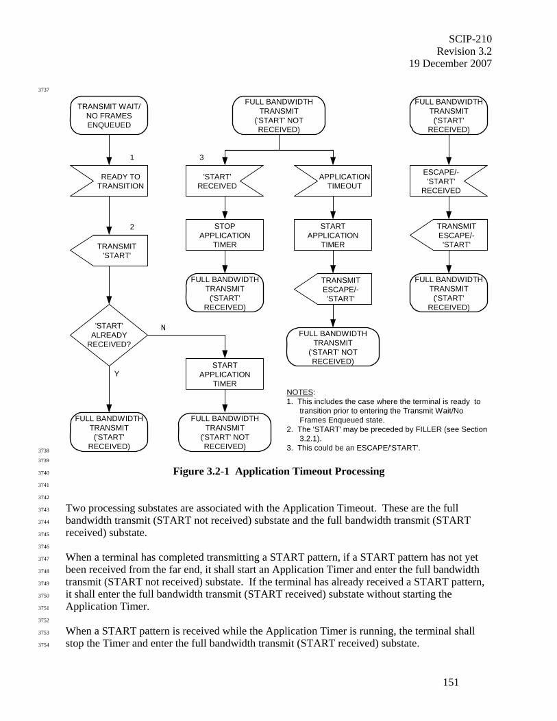
SCIP-210 Revision 3.2
19 December 2007
151
3737
NOTES:1. This includes the case where the terminal is ready to transition prior to entering the Transmit Wait/No Frames Enqueued state.2. The 'START' may be preceded by FILLER (see Section 3.2.1).3. This could be an ESCAPE/'START'.
31
TRANSMIT WAIT/NO FRAMESENQUEUED
2
READY TOTRANSITION
TRANSMIT'START'
STARTAPPLICATION
TIMER
FULL BANDWIDTHTRANSMIT
('START' NOTRECEIVED)
APPLICATIONTIMEOUT
'START'RECEIVED
FULL BANDWIDTHTRANSMIT('START'
RECEIVED)
FULL BANDWIDTHTRANSMIT('START'
RECEIVED)
ESCAPE/-'START'
RECEIVED
TRANSMITESCAPE/-'START'
TRANSMITESCAPE/-'START'
FULL BANDWIDTHTRANSMIT('START'
RECEIVED)
FULL BANDWIDTHTRANSMIT('START'
RECEIVED)
Y
'START'ALREADY
RECEIVED?
N
STOPAPPLICATION
TIMER
STARTAPPLICATION
TIMER
FULL BANDWIDTHTRANSMIT
('START' NOTRECEIVED)
FULL BANDWIDTHTRANSMIT
('START' NOTRECEIVED) 3738
3739
Figure 3.2-1 Application Timeout Processing 3740
3741
3742
Two processing substates are associated with the Application Timeout. These are the full 3743
bandwidth transmit (START not received) substate and the full bandwidth transmit (START 3744
received) substate. 3745
3746
When a terminal has completed transmitting a START pattern, if a START pattern has not yet 3747
been received from the far end, it shall start an Application Timer and enter the full bandwidth 3748
transmit (START not received) substate. If the terminal has already received a START pattern, 3749
it shall enter the full bandwidth transmit (START received) substate without starting the 3750
Application Timer. 3751
3752
When a START pattern is received while the Application Timer is running, the terminal shall 3753
stop the Timer and enter the full bandwidth transmit (START received) substate. 3754
SCIP-210 Revision 3.2 19 December 2007
152
3755
If an Application Timeout occurs before a START pattern is received, the terminal shall transmit 3756
the ESCAPE/START (the ESCAPE pattern followed immediately by the START pattern), 3757
restart the Application Timer, and remain in the full bandwidth transmit (START not received) 3758
substate. 3759
3760
When the Application Timer has been stopped, a terminal may, under exception conditions, 3761
receive another ESCAPE/START. If this occurs, the terminal shall transmit another 3762
ESCAPE/START and continue in the full bandwidth transmit (START received) substate. The 3763
Application Timer is not restarted. 3764
3765
Editor's Note: It is important that the Application Timeout value always be greater than the round-trip path delay; otherwise, the terminals may fall into continuous ‘ping-pong’ retransmissions of the ESCAPE/START patterns. The recommended initial value for the Application Timeout in Table 2.4-1 should be adequate for most, if not all, connections.
3766
3767
3.2.2 Reliable Transport Applications 3768
3769
Applications defined as reliable transport (e.g., Secure Reliable Transport Asynchronous Data) 3770
are required to retain the Transport Layer functionality after completing call setup or Mode 3771
Change signaling. This is accomplished as follows. 3772
3773
When a reliable transport application has been chosen in the initial SCIP call setup or Mode 3774
Change signaling, the application shall begin when the following conditions have been met: 3775
3776
(a) the final SCIP call setup or control message has been transmitted, 3777
3778
(b) there are no remaining outstanding Transport Layer frames in the final SCIP call setup or 3779
control message received from the far end terminal, and 3780
3781
(c) all outstanding Transport Layer frames have been acknowledged for the last message 3782
transmitted. 3783
3784
When these conditions have been met, the application shall begin transmitting reliable transport 3785
application messages (e.g., Secure Reliable Transport Asynchronous Data messages), when they 3786
are available, without terminating the Transport Layer. FILLER and START patterns shall not 3787
be sent following call setup or control signaling, since the Transport Layer functionality is not 3788
being bypassed. Therefore, there is no Application Timeout. Likewise, ESCAPE shall not be 3789
sent when transitioning back to call control signaling. 3790
3791
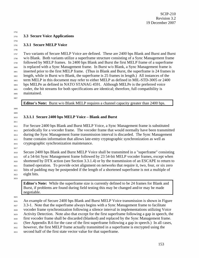
SCIP-210 Revision 3.2
19 December 2007
153
3792
3.3 Secure Voice Applications 3793
3794
3.3.1 Secure MELP Voice 3795
3796
Two variants of Secure MELP Voice are defined. These are 2400 bps Blank and Burst and Burst 3797
w/o Blank. Both variants utilize a superframe structure consisting of a Sync Management frame 3798
followed by MELP frames. In 2400 bps Blank and Burst the first MELP frame of a superframe 3799
is replaced with a Sync Management frame. In Burst w/o Blank, a Sync Management frame is 3800
inserted prior to the first MELP frame. (Thus in Blank and Burst, the superframe is 24 frames in 3801
length, while in Burst w/o Blank, the superframe is 25 frames in length.) All instances of the 3802
term MELP in this document may refer to either MELP as defined in MIL-STD-3005 or 2400 3803
bps MELPe as defined in NATO STANAG 4591. Although MELPe is the preferred voice 3804
coder, the bit streams for both specifications are identical; therefore, full compatibility is 3805
maintained. 3806
3807
Editor's Note: Burst w/o Blank MELP requires a channel capacity greater than 2400 bps. 3808
3809
3.3.1.1 Secure 2400 bps MELP Voice – Blank and Burst 3810
3811
For Secure 2400 bps Blank and Burst MELP Voice, a Sync Management frame is substituted 3812
periodically for a vocoder frame. The vocoder frame that would normally have been transmitted 3813
during the Sync Management frame transmission interval is discarded. The Sync Management 3814
frame contains information that allows late-entry cryptographic synchronization as well as 3815
cryptographic synchronization maintenance. 3816
3817
Secure 2400 bps Blank and Burst MELP Voice shall be transmitted in a "superframe" consisting 3818
of a 54-bit Sync Management frame followed by 23 54-bit MELP vocoder frames, except when 3819
shortened by DTX action (see Section 3.3.1.4) or by the transmission of an ESCAPE to return to 3820
framed operation. To provide octet alignment on networks that require it, two, four, or six zero 3821
bits of padding may be postpended if the length of a shortened superframe is not a multiple of 3822
eight bits. 3823
3824
Editor's Note: While the superframe size is currently defined to be 24 frames for Blank and Burst, if problems are found during field testing this may be changed and/or may be made negotiable.
3825
An example of Secure 2400 bps Blank and Burst MELP Voice transmission is shown in Figure 3826
3.3-1. Note that the superframe always begins with a Sync Management frame to facilitate 3827
vocoder frame synchronization following a silence interval in implementations utilizing Voice 3828
Activity Detection. Note also that except for the first superframe following a gap in speech, the 3829
first vocoder frame shall be discarded (blanked) and replaced by the Sync Management frame. 3830
(See Appendix B.6 for the case of the first superframe following a gap in speech.) In all cases, 3831
however, the first MELP frame actually transmitted in a superframe is encrypted using the 3832
second half of the first state vector value for that superframe. 3833
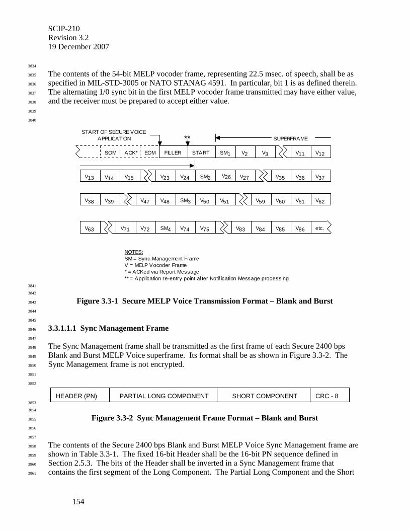
SCIP-210 Revision 3.2 19 December 2007
154
3834
The contents of the 54-bit MELP vocoder frame, representing 22.5 msec. of speech, shall be as 3835
specified in MIL-STD-3005 or NATO STANAG 4591. In particular, bit 1 is as defined therein. 3836
The alternating 1/0 sync bit in the first MELP vocoder frame transmitted may have either value, 3837
and the receiver must be prepared to accept either value. 3838
3839
3840
START OF SECURE VOICEAPPLICATION
V14 V15 V23 V24 V26 V27 V35
V38 V39 V48V47 V62
V63
V59 V60
V72 V74 V75 V86V83 V84 etc.V71
V50 V51
FILLER START V2 V11 V12
V36
SOM ACK* EOM SM1
V13 SM2 V37
SM3 V61
SM4 V85
SUPERFRAME
V3
NOTES:SM = Sync Management FrameV = MELP Vocoder Frame * = ACKed via Report Message** = Application re-entry point af ter Notif ication Message processing
**
3841
3842
Figure 3.3-1 Secure MELP Voice Transmission Format – Blank and Burst 3843
3844
3845
3.3.1.1.1 Sync Management Frame 3846
3847
The Sync Management frame shall be transmitted as the first frame of each Secure 2400 bps 3848
Blank and Burst MELP Voice superframe. Its format shall be as shown in Figure 3.3-2. The 3849
Sync Management frame is not encrypted. 3850
3851
3852
HEADER (PN) CRC - 8PARTIAL LONG COMPONENT SHORT COMPONENT 3853
3854
Figure 3.3-2 Sync Management Frame Format – Blank and Burst 3855
3856
3857
The contents of the Secure 2400 bps Blank and Burst MELP Voice Sync Management frame are 3858
shown in Table 3.3-1. The fixed 16-bit Header shall be the 16-bit PN sequence defined in 3859
Section 2.5.3. The bits of the Header shall be inverted in a Sync Management frame that 3860
contains the first segment of the Long Component. The Partial Long Component and the Short 3861
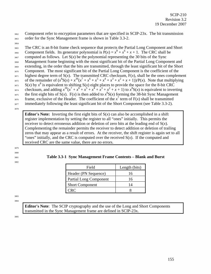
SCIP-210 Revision 3.2
19 December 2007
155
Component refer to encryption parameters that are specified in SCIP-23x. The bit transmission 3862
order for the Sync Management frame is shown in Table 3.3-2. 3863
3864
The CRC is an 8-bit frame check sequence that protects the Partial Long Component and Short 3865
Component fields. Its generator polynomial is P(x) = x8 + x6 + x + 1. The CRC shall be 3866
computed as follows. Let S(x) be the polynomial representing the 30 bits of the Sync 3867
Management frame beginning with the most significant bit of the Partial Long Component and 3868
extending, in the order that the bits are transmitted, through the least significant bit of the Short 3869
Component. The most significant bit of the Partial Long Component is the coefficient of the 3870
highest degree term of S(x). The transmitted CRC checksum, F(x), shall be the ones complement 3871
of the remainder of (x8S(x) + x30(x7 + x6 + x5 + x4 + x3 + x2 + x + 1))/P(x). Note that multiplying 3872
S(x) by x8 is equivalent to shifting S(x) eight places to provide the space for the 8-bit CRC 3873
checksum, and adding x30(x7 + x6 + x5 + x4 + x3 + x2 + x + 1) to x8S(x) is equivalent to inverting 3874
the first eight bits of S(x). F(x) is then added to x8S(x) forming the 38-bit Sync Management 3875
frame, exclusive of the Header. The coefficient of the x7 term of F(x) shall be transmitted 3876
immediately following the least significant bit of the Short Component (see Table 3.3-2). 3877
3878
Editor's Note: Inverting the first eight bits of S(x) can also be accomplished in a shift register implementation by setting the register to all “ones” initially. This permits the receiver to detect erroneous addition or deletion of zero bits at the leading end of S(x). Complementing the remainder permits the receiver to detect addition or deletion of trailing zeros that may appear as a result of errors. At the receiver, the shift register is again set to all “ones” initially, and the CRC is computed over the received S(x). If the computed and received CRC are the same value, there are no errors.
3879
3880
Table 3.3-1 Sync Management Frame Contents – Blank and Burst 3881
3882
Field Length (bits) Header (PN Sequence) 16 Partial Long Component 16 Short Component 14 CRC 8
3883
3884
Editor's Note: The SCIP cryptography and the use of the Long and Short Components transmitted in the Sync Management frame are defined in SCIP-23x.
3885

SCIP-210 Revision 3.2 19 December 2007
156
3886
3.3.1.1.2 Encryption and Transmission Ordering 3887
3888
MELP vocoder data is generated in 54-bit frames. Vocoder frames may be padded to 56 bits (to 3889
provide octet alignment if required) prior to encryption, but only the output bits corresponding to 3890
the first 54 bits of the input shall be transmitted. Data ordering for encrypting MELP vocoder 3891
data is specified in SCIP-230 or SCIP-231, Section 4.1.1.1; or SCIP-232, Section 4.1.1. Note 3892
that the vocoder frames that are deleted to allow for insertion of Sync Management frames shall 3893
be deleted following encryption. 3894
3895
Encrypted MELP vocoder frames shall have Sync Management frames inserted (in place of the 3896
deleted vocoder frames) and shall be formatted into superframes as shown in Table 3.3-2. The 3897
superframes shall then be passed, in ascending octet order beginning with the first octet of the 3898
Header, to the lower layers for transmission. If the length of a shortened superframe is not a 3899
multiple of eight bits, sufficient padding bits may be added to make the resulting padded 3900
superframe a multiple of eight bits, if the underlying transport service requires octet alignment. 3901
3902
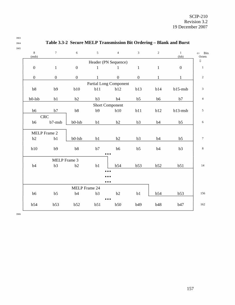
SCIP-210 Revision 3.2
19 December 2007
157
3903
Table 3.3-2 Secure MELP Transmission Bit Ordering – Blank and Burst 3904
3905
8 7 6 5 4 3 2 1 ⇐ Bits (msb) (lsb) Octets
Header (PN Sequence) ⇓
0 1 0 1 1 1 1 0 1
0 0 0 1 0 0 1 1 2
Partial Long Component
b8 b9 b10 b11 b12 b13 b14 b15-msb 3
b0-lsb b1 b2 b3 b4 b5 b6 b7 4
Short Component
b6 b7 b8 b9 b10 b11 b12 b13-msb 5
CRC
b6 b7-msb b0-lsb b1 b2 b3 b4 b5 6
MELP Frame 2
b2 b1 b0-lsb b1 b2 b3 b4 b5 7
b10 b9 b8 b7 b6 b5 b4 b3 8
• • •
MELP Frame 3
b4 b3 b2 b1 b54 b53 b52 b51 14
• • •
• • •
• • •
MELP Frame 24
b6 b5 b4 b3 b2 b1 b54 b53 156
• • •
b54 b53 b52 b51 b50 b49 b48 b47 162
3906
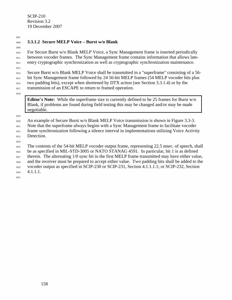
SCIP-210 Revision 3.2 19 December 2007
158
3907
3.3.1.2 Secure MELP Voice – Burst w/o Blank 3908
3909
For Secure Burst w/o Blank MELP Voice, a Sync Management frame is inserted periodically 3910
between vocoder frames. The Sync Management frame contains information that allows late-3911
entry cryptographic synchronization as well as cryptographic synchronization maintenance. 3912
3913
Secure Burst w/o Blank MELP Voice shall be transmitted in a "superframe" consisting of a 56-3914
bit Sync Management frame followed by 24 56-bit MELP frames (54 MELP vocoder bits plus 3915
two padding bits), except when shortened by DTX action (see Section 3.3.1.4) or by the 3916
transmission of an ESCAPE to return to framed operation. 3917
3918
Editor's Note: While the superframe size is currently defined to be 25 frames for Burst w/o Blank, if problems are found during field testing this may be changed and/or may be made negotiable.
3919
An example of Secure Burst w/o Blank MELP Voice transmission is shown in Figure 3.3-3. 3920
Note that the superframe always begins with a Sync Management frame to facilitate vocoder 3921
frame synchronization following a silence interval in implementations utilizing Voice Activity 3922
Detection. 3923
3924
The contents of the 54-bit MELP vocoder output frame, representing 22.5 msec. of speech, shall 3925
be as specified in MIL-STD-3005 or NATO STANAG 4591. In particular, bit 1 is as defined 3926
therein. The alternating 1/0 sync bit in the first MELP frame transmitted may have either value, 3927
and the receiver must be prepared to accept either value. Two padding bits shall be added to the 3928
vocoder output as specified in SCIP-230 or SCIP-231, Section 4.1.1.1.1; or SCIP-232, Section 3929
4.1.1.1. 3930
3931
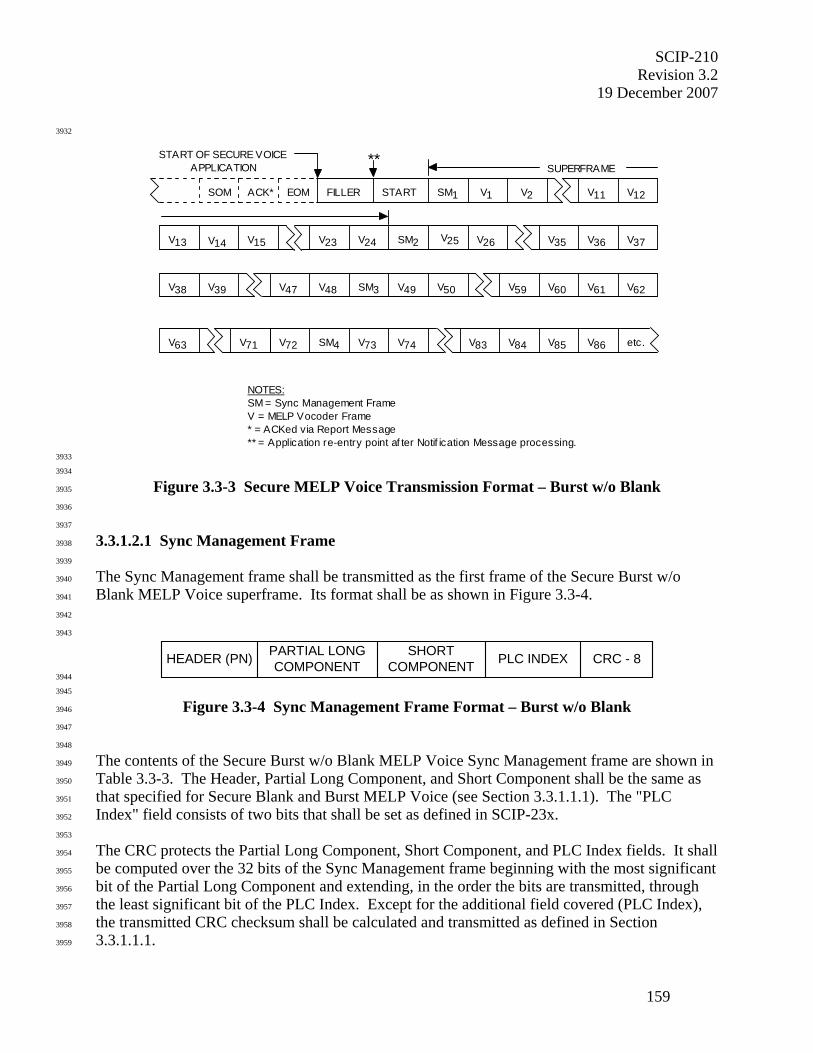
SCIP-210 Revision 3.2
19 December 2007
159
3932
V14 V15 V23 V24 V25 V26 V35
V38 V39 V48V47 V62
V63
V59 V60
V72 V73 V74 V86V83 V84 etc.V71
V49 V50
FILLER START V1 V11 V12
V36
SOM ACK* EOM SM1
V13 SM2 V37
SM3 V61
SM4 V85
SUPERFRAME
V2
NOTES:SM = Sync Management FrameV = MELP Vocoder Frame * = ACKed via Report Message** = Application re-entry point af ter Notif ication Message processing.
** START OF SECURE VOICEAPPLICATION
3933
3934
Figure 3.3-3 Secure MELP Voice Transmission Format – Burst w/o Blank 3935
3936
3937
3.3.1.2.1 Sync Management Frame 3938
3939
The Sync Management frame shall be transmitted as the first frame of the Secure Burst w/o 3940
Blank MELP Voice superframe. Its format shall be as shown in Figure 3.3-4. 3941
3942
3943
HEADER (PN) PLC INDEXPARTIAL LONGCOMPONENT
SHORTCOMPONENT CRC - 8
3944
3945
Figure 3.3-4 Sync Management Frame Format – Burst w/o Blank 3946
3947
3948
The contents of the Secure Burst w/o Blank MELP Voice Sync Management frame are shown in 3949
Table 3.3-3. The Header, Partial Long Component, and Short Component shall be the same as 3950
that specified for Secure Blank and Burst MELP Voice (see Section 3.3.1.1.1). The "PLC 3951
Index" field consists of two bits that shall be set as defined in SCIP-23x. 3952
3953
The CRC protects the Partial Long Component, Short Component, and PLC Index fields. It shall 3954
be computed over the 32 bits of the Sync Management frame beginning with the most significant 3955
bit of the Partial Long Component and extending, in the order the bits are transmitted, through 3956
the least significant bit of the PLC Index. Except for the additional field covered (PLC Index), 3957
the transmitted CRC checksum shall be calculated and transmitted as defined in Section 3958
3.3.1.1.1. 3959
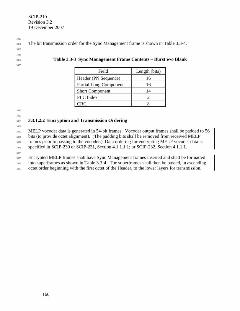
SCIP-210 Revision 3.2 19 December 2007
160
3960
The bit transmission order for the Sync Management frame is shown in Table 3.3-4. 3961
3962
3963
Table 3.3-3 Sync Management Frame Contents – Burst w/o Blank 3964
3965
Field Length (bits) Header (PN Sequence) 16 Partial Long Component 16 Short Component 14 PLC Index 2 CRC 8
3966
3967
3.3.1.2.2 Encryption and Transmission Ordering 3968
3969
MELP vocoder data is generated in 54-bit frames. Vocoder output frames shall be padded to 56 3970
bits (to provide octet alignment). (The padding bits shall be removed from received MELP 3971
frames prior to passing to the vocoder.) Data ordering for encrypting MELP vocoder data is 3972
specified in SCIP-230 or SCIP-231, Section 4.1.1.1.1; or SCIP-232, Section 4.1.1.1. 3973
3974
Encrypted MELP frames shall have Sync Management frames inserted and shall be formatted 3975
into superframes as shown in Table 3.3-4. The superframes shall then be passed, in ascending 3976
octet order beginning with the first octet of the Header, to the lower layers for transmission. 3977
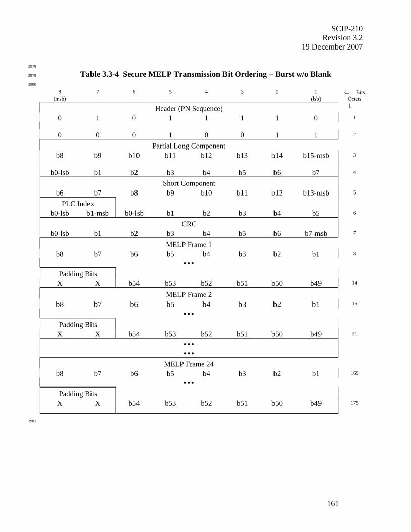
SCIP-210 Revision 3.2
19 December 2007
161
3978
Table 3.3-4 Secure MELP Transmission Bit Ordering – Burst w/o Blank 3979
3980
8 7 6 5 4 3 2 1 ⇐ Bits (msb) (lsb) Octets
Header (PN Sequence) ⇓
0 1 0 1 1 1 1 0 1
0 0 0 1 0 0 1 1 2
Partial Long Component
b8 b9 b10 b11 b12 b13 b14 b15-msb 3
b0-lsb b1 b2 b3 b4 b5 b6 b7 4
Short Component
b6 b7 b8 b9 b10 b11 b12 b13-msb 5
PLC Index
b0-lsb b1-msb b0-lsb b1 b2 b3 b4 b5 6
CRC
b0-lsb b1 b2 b3 b4 b5 b6 b7-msb 7
MELP Frame 1
b8 b7 b6 b5 b4 b3 b2 b1 8
• • •
Padding Bits
X X b54 b53 b52 b51 b50 b49 14
MELP Frame 2
b8 b7 b6 b5 b4 b3 b2 b1 15
• • •
Padding Bits
X X b54 b53 b52 b51 b50 b49 21
• • •
• • •
MELP Frame 24
b8 b7 b6 b5 b4 b3 b2 b1 169
• • •
Padding Bits
X X b54 b53 b52 b51 b50 b49 175
3981
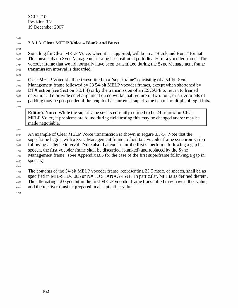
SCIP-210 Revision 3.2 19 December 2007
162
3982
3.3.1.3 Clear MELP Voice – Blank and Burst 3983
3984
Signaling for Clear MELP Voice, when it is supported, will be in a "Blank and Burst" format. 3985
This means that a Sync Management frame is substituted periodically for a vocoder frame. The 3986
vocoder frame that would normally have been transmitted during the Sync Management frame 3987
transmission interval is discarded. 3988
3989
Clear MELP Voice shall be transmitted in a "superframe" consisting of a 54-bit Sync 3990
Management frame followed by 23 54-bit MELP vocoder frames, except when shortened by 3991
DTX action (see Section 3.3.1.4) or by the transmission of an ESCAPE to return to framed 3992
operation. To provide octet alignment on networks that require it, two, four, or six zero bits of 3993
padding may be postpended if the length of a shortened superframe is not a multiple of eight bits. 3994
3995
Editor's Note: While the superframe size is currently defined to be 24 frames for Clear MELP Voice, if problems are found during field testing this may be changed and/or may be made negotiable.
3996
An example of Clear MELP Voice transmission is shown in Figure 3.3-5. Note that the 3997
superframe begins with a Sync Management frame to facilitate vocoder frame synchronization 3998
following a silence interval. Note also that except for the first superframe following a gap in 3999
speech, the first vocoder frame shall be discarded (blanked) and replaced by the Sync 4000
Management frame. (See Appendix B.6 for the case of the first superframe following a gap in 4001
speech.) 4002
4003
The contents of the 54-bit MELP vocoder frame, representing 22.5 msec. of speech, shall be as 4004
specified in MIL-STD-3005 or NATO STANAG 4591. In particular, bit 1 is as defined therein. 4005
The alternating 1/0 sync bit in the first MELP vocoder frame transmitted may have either value, 4006
and the receiver must be prepared to accept either value. 4007
4008
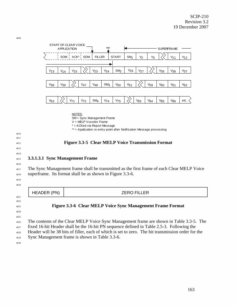
SCIP-210 Revision 3.2
19 December 2007
163
4009
START OF CLEAR VOICEAPPLICATION
V14 V15 V23 V24 V26 V27 V35
V38 V39 V48V47 V62
V63
V59 V60
V72 V74 V75 V86V83 V84 etc.V71
V50 V51
FILLER START V2 V11 V12
V36
SOM ACK* EOM SM1
V13 SM2 V37
SM3 V61
SM4 V85
SUPERFRAME
V3
NOTES:SM = Sync Management FrameV = MELP Vocoder Frame * = ACKed via Report Message** = Application re-entry point af ter Notif ication Message processing
**
4010
4011
Figure 3.3-5 Clear MELP Voice Transmission Format 4012
4013
4014
3.3.1.3.1 Sync Management Frame 4015
4016
The Sync Management frame shall be transmitted as the first frame of each Clear MELP Voice 4017
superframe. Its format shall be as shown in Figure 3.3-6. 4018
4019
4020
HEADER (PN) ZERO FILLER 4021
4022
Figure 3.3-6 Clear MELP Voice Sync Management Frame Format 4023
4024
4025
The contents of the Clear MELP Voice Sync Management frame are shown in Table 3.3-5. The 4026
fixed 16-bit Header shall be the 16-bit PN sequence defined in Table 2.5-3. Following the 4027
Header will be 38 bits of filler, each of which is set to zero. The bit transmission order for the 4028
Sync Management frame is shown in Table 3.3-6. 4029
4030
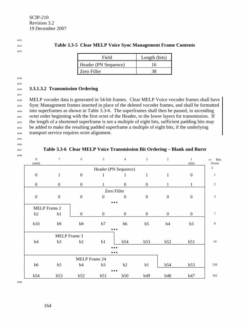
SCIP-210 Revision 3.2 19 December 2007
164
4031
Table 3.3-5 Clear MELP Voice Sync Management Frame Contents 4032
4033
Field Length (bits) Header (PN Sequence) 16 Zero Filler 38
4034
4035
3.3.1.3.2 Transmission Ordering 4036
4037
MELP vocoder data is generated in 54-bit frames. Clear MELP Voice vocoder frames shall have 4038
Sync Management frames inserted in place of the deleted vocoder frames, and shall be formatted 4039
into superframes as shown in Table 3.3-6. The superframes shall then be passed, in ascending 4040
octet order beginning with the first octet of the Header, to the lower layers for transmission. If 4041
the length of a shortened superframe is not a multiple of eight bits, sufficient padding bits may 4042
be added to make the resulting padded superframe a multiple of eight bits, if the underlying 4043
transport service requires octet alignment. 4044
4045
4046
Table 3.3-6 Clear MELP Voice Transmission Bit Ordering – Blank and Burst 4047
4048 8 7 6 5 4 3 2 1 ⇐ Bits
(msb) (lsb) Octets
Header (PN Sequence) ⇓
0 1 0 1 1 1 1 0 1
0 0 0 1 0 0 1 1 2
Zero Filler
0 0 0 0 0 0 0 0 3
• • •
MELP Frame 2
b2 b1 0 0 0 0 0 0 7
b10 b9 b8 b7 b6 b5 b4 b3 8
• • •
MELP Frame 3
b4 b3 b2 b1 b54 b53 b52 b51 14
• • •
• • •
MELP Frame 24
b6 b5 b4 b3 b2 b1 b54 b53 156
• • •
b54 b53 b52 b51 b50 b49 b48 b47 162
4049
SCIP-210 Revision 3.2
19 December 2007
165
4050
3.3.1.4 Voice Activity Factor Processing 4051
4052
Two options are defined for SCIP MELP Voice. These are Discontinuous Voice Transmission 4053
(DTX) and Force Continuous Transmission (FCT), as described below. Where terminals have 4054
implemented both DTX and FCT, Secure Voice Options are provided in Section 2.2.6.2 for 4055
negotiating which one to use. 4056
4057
Editor's Note: A cellular phone may support Discontinuous Voice Transmission so that it will cease transmitting when the user stops speaking. However, for security reasons, it may be required that the phone be set for Force Continuous Transmission. All current (as of 7/02) Secure MELP Voice implementations are FCT only.
4058
4059
3.3.1.4.1 Discontinuous Voice Transmission 4060
4061
Discontinuous voice transmission (DTX) is specified in Appendix B. This Section only 4062
addresses the signaling associated with it. 4063
4064
During DTX operation, when voice activity is initially detected a superframe shall be formatted 4065
and transmitted. For as long as voice is detected, full length superframes (defined in the sections 4066
that define the individual applications) shall be continuously transmitted. When silence is 4067
detected, two or more Grace Period frames (defined in Appendix B.3) shall be transmitted in 4068
place of the corresponding number of MELP frames. Transmission shall then cease for at least n 4069
MELP frames, where n is the Minimum Blank Period (defined in Appendix B.4). The final 4070
superframe before transmission ceases may be shorter than a full length superframe; it contains a 4071
Sync Management frame, zero or more MELP frames, and one or more Grace Period frames. 4072
After a period of silence, when voice is again detected, transmission of MELP frames is 4073
restarted. The first frame transmitted following a gap shall be a Sync Management frame, 4074
regardless of the duration of the gap. This Sync Management frame shall contain the next value 4075
in the cyclic rotation of Partial Long Term Components that would normally follow the value 4076
transmitted in the last Sync Management frame prior to the gap. The crypto is not flywheeled 4077
during gaps in voice transmission. MELP frame transmission continues with full length 4078
superframes until silence is again detected. 4079
4080
4081
3.3.1.4.2 Force Continuous Transmission 4082
4083
Force Continuous Transmission (FCT) applies to both Secure MELP Voice and Clear MELP 4084
Voice applications. 4085
4086
During FCT operation, full length superframes shall be transmitted continuously between the 4087
START (see Section 3.2) and the ESCAPE (see Section 2.1.4). The MELP vocoder is run 4088
continuously, and all frames that are generated (excluding blanked frames) are transmitted. 4089
4090
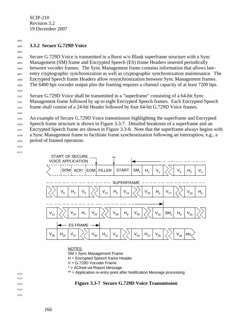
SCIP-210 Revision 3.2 19 December 2007
166
4091
3.3.2 Secure G.729D Voice 4092
4093
Secure G.729D Voice is transmitted in a Burst w/o Blank superframe structure with a Sync 4094
Management (SM) frame and Encrypted Speech (ES) frame Headers inserted periodically 4095
between vocoder frames. The Sync Management frame contains information that allows late-4096
entry cryptographic synchronization as well as cryptographic synchronization maintenance. The 4097
Encrypted Speech frame Headers allow resynchronization between Sync Management frames. 4098
The 6400 bps vocoder output plus the framing requires a channel capacity of at least 7200 bps. 4099
4100
Secure G.729D Voice shall be transmitted in a "superframe" consisting of a 64-bit Sync 4101
Management frame followed by up to eight Encrypted Speech frames. Each Encrypted Speech 4102
frame shall consist of a 24-bit Header followed by four 64-bit G.729D Voice frames. 4103
4104
An example of Secure G.729D Voice transmission highlighting the superframe and Encrypted 4105
Speech frame structure is shown in Figure 3.3-7. Detailed breakouts of a superframe and an 4106
Encrypted Speech frame are shown in Figure 3.3-8. Note that the superframe always begins with 4107
a Sync Management frame to facilitate frame synchronization following an interruption, e.g., a 4108
period of framed operation. 4109
4110
4111
NOTES:SM = Sync Management FrameH = Encrypted Speech frame HeaderV = G.729D Vocoder Frame* = ACKed via Report Message** = Application re-entry point after Notification Message processing
FILLER START H1SOM ACK* EOM SM1 V1
SUPERFRAME
** START OF SECUREVOICE APPLICATION
H9SM2V32
etc.H10
V4 H2
V44 V45V37
V13
V33
H11 V41V40
V12H3
V36
V9 H4 H5V16V8 V17
V25
V20
V21 H7V24 H8V28
H6
V29
H12
V5
V48
ES FRAME
4112
4113
Figure 3.3-7 Secure G.729D Voice Transmission 4114
4115
4116
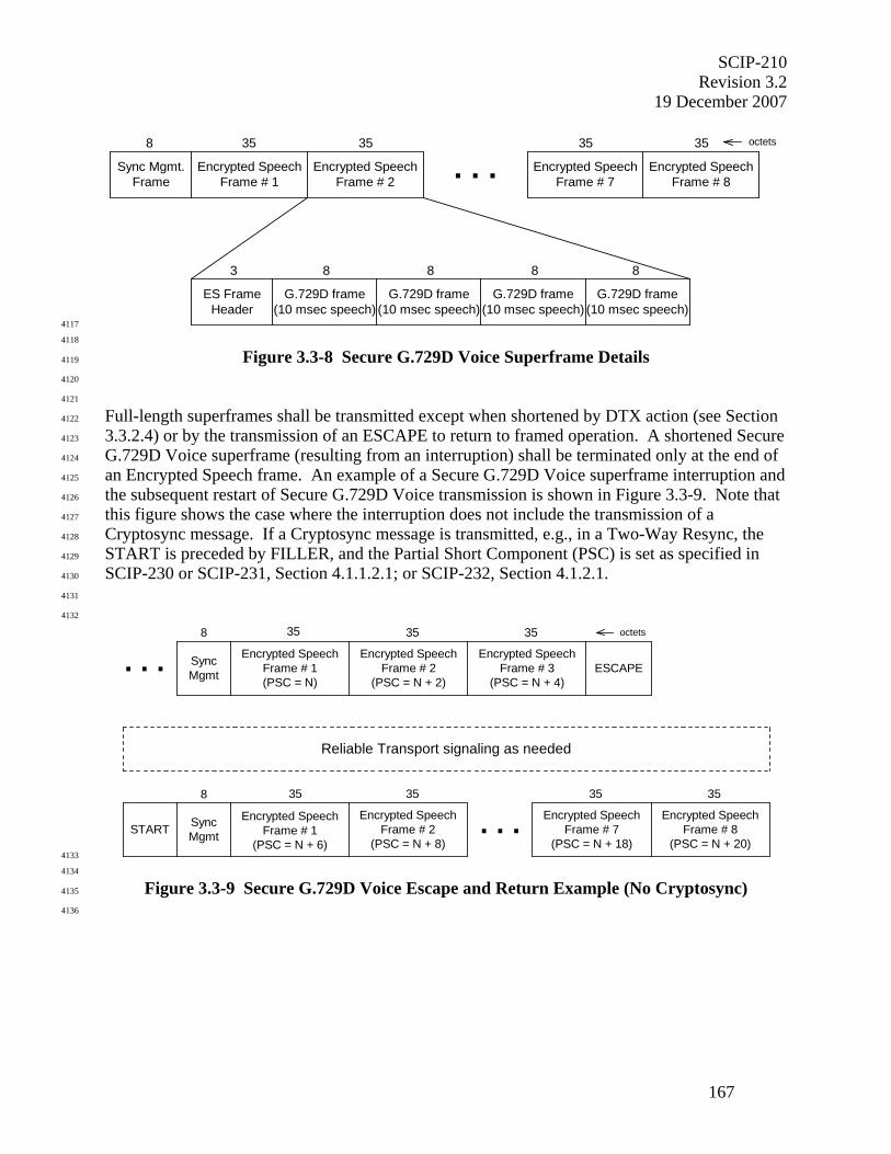
SCIP-210 Revision 3.2
19 December 2007
167
8 35 35
Sync Mgmt.Frame
Encrypted SpeechFrame # 1 . . .Encrypted Speech
Frame # 2
8
G.729D frame(10 msec speech)
3
ES FrameHeader
8 8 8
35 35
Encrypted SpeechFrame # 7
Encrypted SpeechFrame # 8
G.729D frame(10 msec speech)
G.729D frame(10 msec speech)
G.729D frame(10 msec speech)
octets
4117
4118
Figure 3.3-8 Secure G.729D Voice Superframe Details 4119
4120
4121
Full-length superframes shall be transmitted except when shortened by DTX action (see Section 4122
3.3.2.4) or by the transmission of an ESCAPE to return to framed operation. A shortened Secure 4123
G.729D Voice superframe (resulting from an interruption) shall be terminated only at the end of 4124
an Encrypted Speech frame. An example of a Secure G.729D Voice superframe interruption and 4125
the subsequent restart of Secure G.729D Voice transmission is shown in Figure 3.3-9. Note that 4126
this figure shows the case where the interruption does not include the transmission of a 4127
Cryptosync message. If a Cryptosync message is transmitted, e.g., in a Two-Way Resync, the 4128
START is preceded by FILLER, and the Partial Short Component (PSC) is set as specified in 4129
SCIP-230 or SCIP-231, Section 4.1.1.2.1; or SCIP-232, Section 4.1.2.1. 4130
4131
4132
8 35 35
SyncMgmt
Encrypted SpeechFrame # 1
(PSC = N + 6)
Encrypted SpeechFrame # 2
(PSC = N + 8)START
35 35
Encrypted SpeechFrame # 7
(PSC = N + 18)
Encrypted SpeechFrame # 8
(PSC = N + 20). . .
Reliable Transport signaling as needed
8 35 35 35
SyncMgmt
Encrypted SpeechFrame # 1(PSC = N)
Encrypted SpeechFrame # 2
(PSC = N + 2)
Encrypted SpeechFrame # 3
(PSC = N + 4)ESCAPE. . .
octets
4133
4134
Figure 3.3-9 Secure G.729D Voice Escape and Return Example (No Cryptosync) 4135
4136
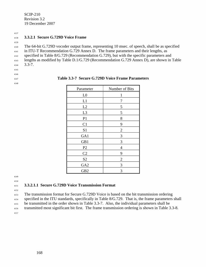
SCIP-210 Revision 3.2 19 December 2007
168
4137
3.3.2.1 Secure G.729D Voice Frame 4138
4139
The 64-bit G.729D vocoder output frame, representing 10 msec. of speech, shall be as specified 4140
in ITU-T Recommendation G.729 Annex D. The frame parameters and their lengths, as 4141
specified in Table 8/G.729 (Recommendation G.729), but with the specific parameters and 4142
lengths as modified by Table D.1/G.729 (Recommendation G.729 Annex D), are shown in Table 4143
3.3-7. 4144
4145
4146
Table 3.3-7 Secure G.729D Voice Frame Parameters 4147
4148
Parameter Number of Bits L0 1 L1 7 L2 5 L3 5 P1 8 C1 9 S1 2
GA1 3 GB1 3 P2 4 C2 9 S2 2
GA2 3 GB2 3
4149
4150
3.3.2.1.1 Secure G.729D Voice Transmission Format 4151
4152
The transmission format for Secure G.729D Voice is based on the bit transmission ordering 4153
specified in the ITU standards, specifically in Table 8/G.729. That is, the frame parameters shall 4154
be transmitted in the order shown in Table 3.3-7. Also, the individual parameters shall be 4155
transmitted most significant bit first. The frame transmission ordering is shown in Table 3.3-8. 4156
4157
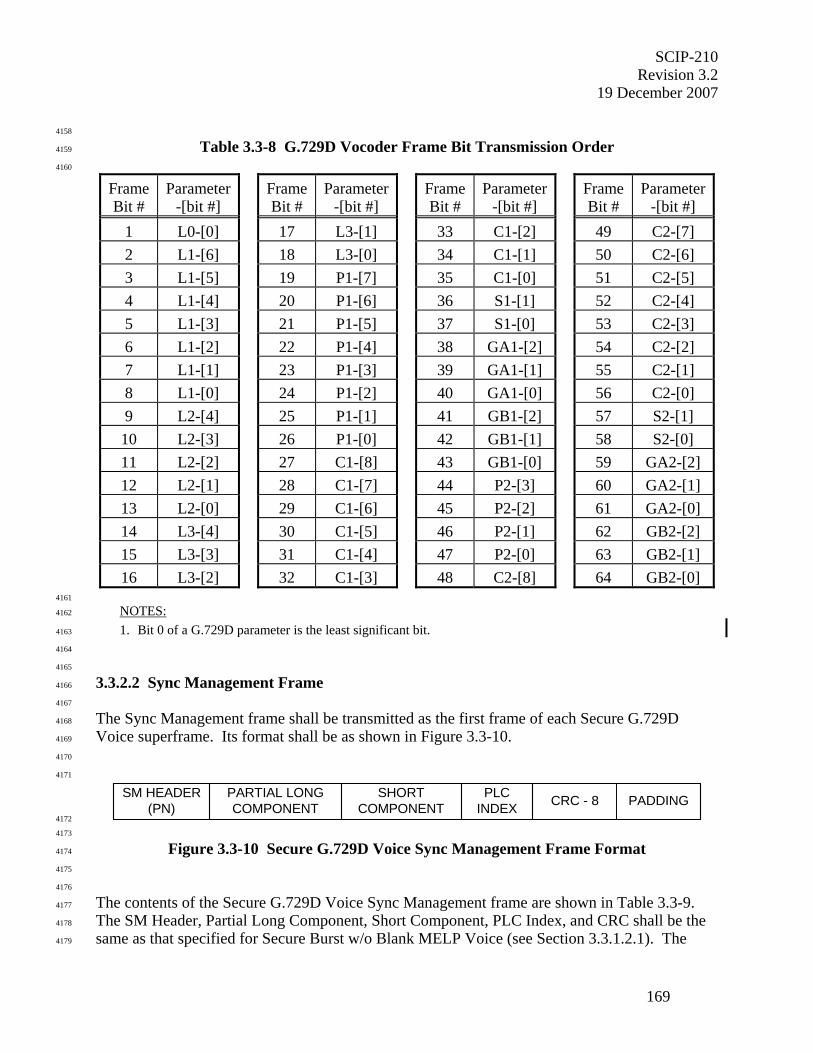
SCIP-210 Revision 3.2
19 December 2007
169
4158
Table 3.3-8 G.729D Vocoder Frame Bit Transmission Order 4159
4160
Frame Bit #
Parameter -[bit #]
Frame Bit #
Parameter -[bit #]
Frame Bit #
Parameter -[bit #]
Frame Bit #
Parameter -[bit #]
1 L0-[0] 17 L3-[1] 33 C1-[2] 49 C2-[7] 2 L1-[6] 18 L3-[0] 34 C1-[1] 50 C2-[6] 3 L1-[5] 19 P1-[7] 35 C1-[0] 51 C2-[5] 4 L1-[4] 20 P1-[6] 36 S1-[1] 52 C2-[4] 5 L1-[3] 21 P1-[5] 37 S1-[0] 53 C2-[3] 6 L1-[2] 22 P1-[4] 38 GA1-[2] 54 C2-[2] 7 L1-[1] 23 P1-[3] 39 GA1-[1] 55 C2-[1] 8 L1-[0] 24 P1-[2] 40 GA1-[0] 56 C2-[0] 9 L2-[4] 25 P1-[1] 41 GB1-[2] 57 S2-[1] 10 L2-[3] 26 P1-[0] 42 GB1-[1] 58 S2-[0] 11 L2-[2] 27 C1-[8] 43 GB1-[0] 59 GA2-[2] 12 L2-[1] 28 C1-[7] 44 P2-[3] 60 GA2-[1] 13 L2-[0] 29 C1-[6] 45 P2-[2] 61 GA2-[0] 14 L3-[4] 30 C1-[5] 46 P2-[1] 62 GB2-[2] 15 L3-[3] 31 C1-[4] 47 P2-[0] 63 GB2-[1] 16 L3-[2] 32 C1-[3] 48 C2-[8] 64 GB2-[0]
4161
NOTES: 4162
1. Bit 0 of a G.729D parameter is the least significant bit. 4163
4164
4165
3.3.2.2 Sync Management Frame 4166
4167
The Sync Management frame shall be transmitted as the first frame of each Secure G.729D 4168
Voice superframe. Its format shall be as shown in Figure 3.3-10. 4169
4170
4171
SM HEADER(PN)
PLCINDEX
PARTIAL LONGCOMPONENT
SHORTCOMPONENT CRC - 8 PADDING
4172
4173
Figure 3.3-10 Secure G.729D Voice Sync Management Frame Format 4174
4175
4176
The contents of the Secure G.729D Voice Sync Management frame are shown in Table 3.3-9. 4177
The SM Header, Partial Long Component, Short Component, PLC Index, and CRC shall be the 4178
same as that specified for Secure Burst w/o Blank MELP Voice (see Section 3.3.1.2.1). The 4179
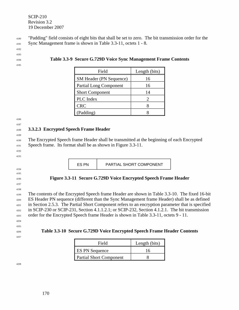
SCIP-210 Revision 3.2 19 December 2007
170
"Padding" field consists of eight bits that shall be set to zero. The bit transmission order for the 4180
Sync Management frame is shown in Table 3.3-11, octets 1 - 8. 4181
4182
4183
Table 3.3-9 Secure G.729D Voice Sync Management Frame Contents 4184
4185
Field Length (bits) SM Header (PN Sequence) 16 Partial Long Component 16 Short Component 14 PLC Index 2 CRC 8 (Padding) 8
4186
4187
3.3.2.3 Encrypted Speech Frame Header 4188
4189
The Encrypted Speech frame Header shall be transmitted at the beginning of each Encrypted 4190
Speech frame. Its format shall be as shown in Figure 3.3-11. 4191
4192
4193
ES PN PARTIAL SHORT COMPONENT 4194
4195
Figure 3.3-11 Secure G.729D Voice Encrypted Speech Frame Header 4196
4197
4198
The contents of the Encrypted Speech frame Header are shown in Table 3.3-10. The fixed 16-bit 4199
ES Header PN sequence (different than the Sync Management frame Header) shall be as defined 4200
in Section 2.5.3. The Partial Short Component refers to an encryption parameter that is specified 4201
in SCIP-230 or SCIP-231, Section 4.1.1.2.1; or SCIP-232, Section 4.1.2.1. The bit transmission 4202
order for the Encrypted Speech frame Header is shown in Table 3.3-11, octets 9 - 11. 4203
4204
4205
Table 3.3-10 Secure G.729D Voice Encrypted Speech Frame Header Contents 4206
4207
Field Length (bits) ES PN Sequence 16 Partial Short Component 8
4208
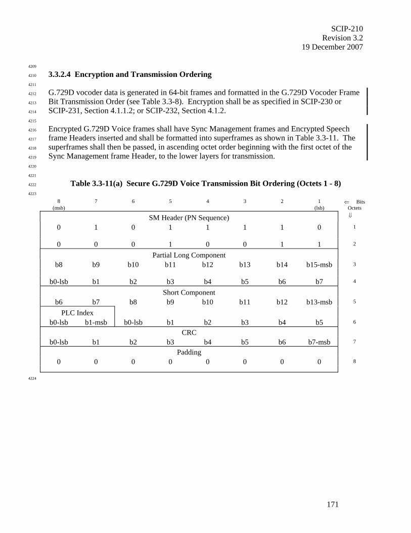
SCIP-210 Revision 3.2
19 December 2007
171
4209
3.3.2.4 Encryption and Transmission Ordering 4210
4211
G.729D vocoder data is generated in 64-bit frames and formatted in the G.729D Vocoder Frame 4212
Bit Transmission Order (see Table 3.3-8). Encryption shall be as specified in SCIP-230 or 4213
SCIP-231, Section 4.1.1.2; or SCIP-232, Section 4.1.2. 4214
4215
Encrypted G.729D Voice frames shall have Sync Management frames and Encrypted Speech 4216
frame Headers inserted and shall be formatted into superframes as shown in Table 3.3-11. The 4217
superframes shall then be passed, in ascending octet order beginning with the first octet of the 4218
Sync Management frame Header, to the lower layers for transmission. 4219
4220
4221
Table 3.3-11(a) Secure G.729D Voice Transmission Bit Ordering (Octets 1 - 8) 4222
4223
8 7 6 5 4 3 2 1 ⇐ Bits (msb) (lsb) Octets
SM Header (PN Sequence) ⇓
0 1 0 1 1 1 1 0 1
0 0 0 1 0 0 1 1 2
Partial Long Component
b8 b9 b10 b11 b12 b13 b14 b15-msb 3
b0-lsb b1 b2 b3 b4 b5 b6 b7 4
Short Component
b6 b7 b8 b9 b10 b11 b12 b13-msb 5
PLC Index
b0-lsb b1-msb b0-lsb b1 b2 b3 b4 b5 6
CRC
b0-lsb b1 b2 b3 b4 b5 b6 b7-msb 7
Padding
0 0 0 0 0 0 0 0 8
4224
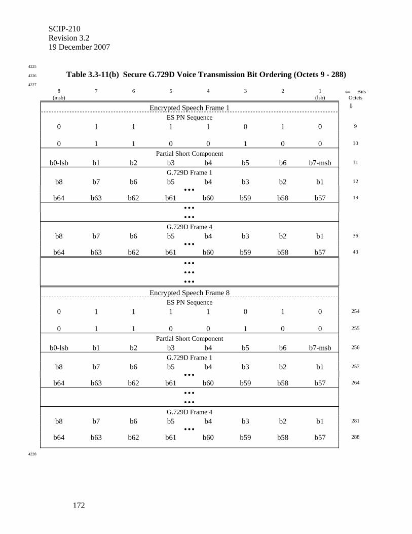
SCIP-210 Revision 3.2 19 December 2007
172
4225
Table 3.3-11(b) Secure G.729D Voice Transmission Bit Ordering (Octets 9 - 288) 4226
4227
8 7 6 5 4 3 2 1 ⇐ Bits (msb) (lsb) Octets
Encrypted Speech Frame 1 ⇓
ES PN Sequence
0 1 1 1 1 0 1 0 9
0 1 1 0 0 1 0 0 10
Partial Short Component
b0-lsb b1 b2 b3 b4 b5 b6 b7-msb 11
G.729D Frame 1
b8 b7 b6 b5 b4 b3 b2 b1 12 • • •
b64 b63 b62 b61 b60 b59 b58 b57 19
• • •
• • •
G.729D Frame 4
b8 b7 b6 b5 b4 b3 b2 b1 36 • • •
b64 b63 b62 b61 b60 b59 b58 b57 43
• • •
• • •
• • •
Encrypted Speech Frame 8
ES PN Sequence
0 1 1 1 1 0 1 0 254
0 1 1 0 0 1 0 0 255
Partial Short Component
b0-lsb b1 b2 b3 b4 b5 b6 b7-msb 256
G.729D Frame 1
b8 b7 b6 b5 b4 b3 b2 b1 257 • • •
b64 b63 b62 b61 b60 b59 b58 b57 264
• • •
• • •
G.729D Frame 4
b8 b7 b6 b5 b4 b3 b2 b1 281 • • •
b64 b63 b62 b61 b60 b59 b58 b57 288
4228
SCIP-210 Revision 3.2
19 December 2007
173
4229
3.3.2.5 Discontinuous Voice Transmission 4230
4231
TBSL. 4232
4233
Editor's Note: It is expected that the SCIP approach to DTX will be compatible with G.729 Annex F; however, the details remain to be determined.
4234
4235
3.3.2.6 Force Continuous Transmission 4236
4237
During Force Continuous Transmission (FCT) operation, full-length superframes shall be 4238
transmitted continuously following the START (see Section 3.2) unless interrupted by the 4239
ESCAPE (see Section 2.1.4). The G.729D Active Voice Encoder is run continuously, and all 4240
frames that are generated are transmitted. 4241
4242
4243
3.4 Secure Data Applications 4244
4245
Two secure asynchronous data applications are specified herein: Secure Reliable Transport 4246
Asynchronous Data (the SCIP MER data application defined in Section 3.4.1) and Secure Best 4247
Effort Transport Asynchronous Data (an optional SCIP data application defined in Section 4248
3.4.2). Asynchronous Data Options may be defined in the future for additional data applications 4249
such as Fax or Chat. 4250
4251
4252
3.4.1 Secure Reliable Transport (RT) Asynchronous Data 4253
4254
The Secure Reliable Transport Asynchronous Data application utilizes the same transport 4255
mechanisms as are used for secure call setup messages to deliver user data reliably. Framing, 4256
forward error correction, and residual error detection reduce the maximum throughput for this 4257
application to less than 65% of the channel rate. 4258
4259
Editor’s Note: The reliable transport application specified in this section may be applicable to synchronous data transmission as well, although issues such as indicating valid bits within an octet need to be addressed for synchronous data transmission.
4260
The Secure Reliable Transport (RT) Asynchronous Data application uses the SCIP message 4261
transport mechanisms specified in Section 2.1 to provide reliable delivery of user data to a 4262
receiving terminal. Following initial call setup signaling or Mode Change signaling where the 4263
Secure RT Asynchronous Data application is chosen, the Transport Layer protocol remains in 4264
place and transports Secure RT Asynchronous Data messages. Secure RT Asynchronous Data 4265
messages contain a variable number of user data octets that have been input from the terminal's 4266
data port and encrypted prior to being placed into the User Data fields of these messages. 4267
4268
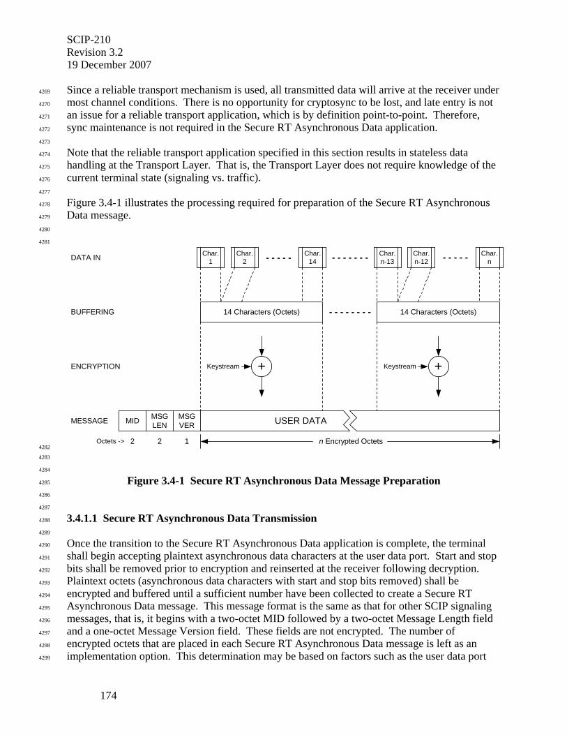
SCIP-210 Revision 3.2 19 December 2007
174
Since a reliable transport mechanism is used, all transmitted data will arrive at the receiver under 4269
most channel conditions. There is no opportunity for cryptosync to be lost, and late entry is not 4270
an issue for a reliable transport application, which is by definition point-to-point. Therefore, 4271
sync maintenance is not required in the Secure RT Asynchronous Data application. 4272
4273
Note that the reliable transport application specified in this section results in stateless data 4274
handling at the Transport Layer. That is, the Transport Layer does not require knowledge of the 4275
current terminal state (signaling vs. traffic). 4276
4277
Figure 3.4-1 illustrates the processing required for preparation of the Secure RT Asynchronous 4278
Data message. 4279
4280
4281
DATA IN
BUFFERING
ENCRYPTION
MESSAGE
Char.1
Char.2
Char.14- - - - - - - - - - - -
14 Characters (Octets) 14 Characters (Octets)- - - - - - - -
Char.n-13
Char.n-12
Char.n- - - - -
MID MSGLEN
MSGVER
+ +Keystream Keystream
n Encrypted Octets2 2 1Octets ->
USER DATA
4282
4283
4284
Figure 3.4-1 Secure RT Asynchronous Data Message Preparation 4285
4286
4287
3.4.1.1 Secure RT Asynchronous Data Transmission 4288
4289
Once the transition to the Secure RT Asynchronous Data application is complete, the terminal 4290
shall begin accepting plaintext asynchronous data characters at the user data port. Start and stop 4291
bits shall be removed prior to encryption and reinserted at the receiver following decryption. 4292
Plaintext octets (asynchronous data characters with start and stop bits removed) shall be 4293
encrypted and buffered until a sufficient number have been collected to create a Secure RT 4294
Asynchronous Data message. This message format is the same as that for other SCIP signaling 4295
messages, that is, it begins with a two-octet MID followed by a two-octet Message Length field 4296
and a one-octet Message Version field. These fields are not encrypted. The number of 4297
encrypted octets that are placed in each Secure RT Asynchronous Data message is left as an 4298
implementation option. This determination may be based on factors such as the user data port 4299
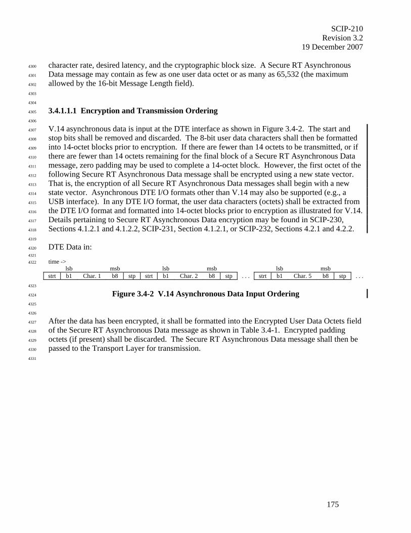
SCIP-210 Revision 3.2
19 December 2007
175
character rate, desired latency, and the cryptographic block size. A Secure RT Asynchronous 4300
Data message may contain as few as one user data octet or as many as 65,532 (the maximum 4301
allowed by the 16-bit Message Length field). 4302
4303
4304
3.4.1.1.1 Encryption and Transmission Ordering 4305
4306
V.14 asynchronous data is input at the DTE interface as shown in Figure 3.4-2. The start and 4307
stop bits shall be removed and discarded. The 8-bit user data characters shall then be formatted 4308
into 14-octet blocks prior to encryption. If there are fewer than 14 octets to be transmitted, or if 4309
there are fewer than 14 octets remaining for the final block of a Secure RT Asynchronous Data 4310
message, zero padding may be used to complete a 14-octet block. However, the first octet of the 4311
following Secure RT Asynchronous Data message shall be encrypted using a new state vector. 4312
That is, the encryption of all Secure RT Asynchronous Data messages shall begin with a new 4313
state vector. Asynchronous DTE I/O formats other than V.14 may also be supported (e.g., a 4314
USB interface). In any DTE I/O format, the user data characters (octets) shall be extracted from 4315
the DTE I/O format and formatted into 14-octet blocks prior to encryption as illustrated for V.14. 4316
Details pertaining to Secure RT Asynchronous Data encryption may be found in SCIP-230, 4317
Sections 4.1.2.1 and 4.1.2.2, SCIP-231, Section 4.1.2.1, or SCIP-232, Sections 4.2.1 and 4.2.2. 4318
4319
DTE Data in: 4320
4321
time -> 4322
lsb msb lsb msb lsb msb strt b1 Char. 1 b8 stp strt b1 Char. 2 b8 stp . . . strt b1 Char. 5 b8 stp . . . 4323
Figure 3.4-2 V.14 Asynchronous Data Input Ordering 4324
4325
4326
After the data has been encrypted, it shall be formatted into the Encrypted User Data Octets field 4327
of the Secure RT Asynchronous Data message as shown in Table 3.4-1. Encrypted padding 4328
octets (if present) shall be discarded. The Secure RT Asynchronous Data message shall then be 4329
passed to the Transport Layer for transmission. 4330
4331
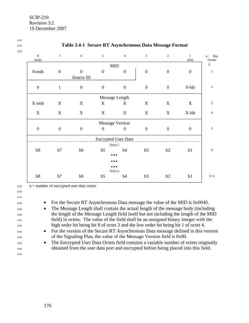
SCIP-210 Revision 3.2 19 December 2007
176
4332
Table 3.4-1 Secure RT Asynchronous Data Message Format 4333
4334
8 7 6 5 4 3 2 1 ⇐ Bits (msb) (lsb) Octets
MID ⇓
0-msb 0 0 0 0 0 0 0 1
Source ID
0 1 0 0 0 0 0 0-lsb 2
Message Length
X-msb X X X X X X X 3
X X X X X X X X-lsb 4
Message Version 0 0 0 0 0 0 0 0 5
Encrypted User Data Octet 1
b8 b7 b6 b5 b4 b3 b2 b1 6 • • • • • • • • •
Octet n
b8 b7 b6 b5 b4 b3 b2 b1 5+n
n = number of encrypted user data octets 4335
4336
4337
• For the Secure RT Asynchronous Data message the value of the MID is 0x0040. 4338
• The Message Length shall contain the actual length of the message body (including 4339
the length of the Message Length field itself but not including the length of the MID 4340
field) in octets. The value of the field shall be an unsigned binary integer with the 4341
high order bit being bit 8 of octet 3 and the low order bit being bit 1 of octet 4. 4342
• For the version of the Secure RT Asynchronous Data message defined in this version 4343
of the Signaling Plan, the value of the Message Version field is 0x00. 4344
• The Encrypted User Data Octets field contains a variable number of octets originally 4345
obtained from the user data port and encrypted before being placed into this field. 4346
4347
SCIP-210 Revision 3.2
19 December 2007
177
4348
3.4.1.1.2 Message Transmission 4349
4350
Each complete Secure RT Asynchronous Data message shall be passed to the Transport Layer 4351
where the processes specified in Section 2.1, including SOM/EOM framing, frame counter, 4352
CRC, FEC, and ACK/NAK using REPORT messages, shall be used to provide reliable 4353
transmission to the far-end terminal. 4354
4355
Appropriate flow control procedures (e.g. RTS/CTS or XON/XOFF) shall be implemented at the 4356
user data port to prevent loss of data in the event data arrives faster than it can be transmitted 4357
over the communications channel. Note that a terminal may also flow control the 4358
communications channel receive data rate if necessary by delaying the normal frame 4359
acknowledgement at the Transport Layer. 4360
4361
If the DTE lowers Request to Send (RTS) while the Secure RT Asynchronous Data application is 4362
active, the terminal shall build and transmit a Secure RT Asynchronous Data message containing 4363
any buffered data, and then cease transmitting. When RTS is again activated, the terminal shall 4364
again start accepting octets from the user data port and building Secure RT Asynchronous Data 4365
messages. The crypto is not flywheeled during periods when the terminal is not transmitting. 4366
4367
4368
3.4.1.2 Secure RT Asynchronous Data Message Reception 4369
4370
Following the transition from signaling to the Secure RT Asynchronous Data application, the 4371
receiving terminal’s Transport Layer shall continue to monitor the communications channel 4372
searching for incoming SOM patterns and the associated transport frames as described in Section 4373
2.1.7. Payload data from the transport frames shall be transferred to the message layer, where 4374
Secure RT Asynchronous Data messages shall be verified and interpreted. 4375
4376
Ciphertext data extracted from the Encrypted User Data Octets field of each Secure RT 4377
Asynchronous Data message (see Table 3.4-1) shall be decrypted in the order shown in Figure 4378
3.4-3. Start and stop bits shall then be reinserted, and the 10-bit data characters shall be 4379
forwarded to the user data port in the order shown in Figure 3.4-2 for V.14 asynchronous data. 4380
For asynchronous DTE I/O formats other than V.14 (e.g., a USB interface) received data shall be 4381
reformatted to the receiving DTE I/O format, which may be different than the sending DTE I/O 4382
format. 4383
4384
4385
3.4.2 Secure Best Effort Transport (BET) Asynchronous Data 4386
4387
The Best Effort Transport (BET) Asynchronous Data application utilizes the channel capacity 4388
efficiently by extracting the asynchronous character octets from their I/O format (e.g., V.14 4389
Start/Stop bits or USB Framing). The channel capacity saved by not transmitting the character 4390
framing allows Sync Management frames to be inserted into the transmitted data at periodic 4391
intervals. 4392
4393
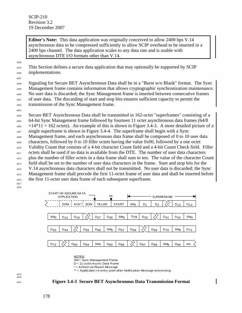
SCIP-210 Revision 3.2 19 December 2007
178
Editor's Note: This data application was originally conceived to allow 2400 bps V.14 asynchronous data to be compressed sufficiently to allow SCIP overhead to be inserted in a 2400 bps channel. The data application scales to any data rate and is usable with asynchronous DTE I/O formats other than V.14.
4394
This Section defines a secure data application that may optionally be supported by SCIP 4395
implementations. 4396
4397
Signaling for Secure BET Asynchronous Data shall be in a "Burst w/o Blank" format. The Sync 4398
Management frame contains information that allows cryptographic synchronization maintenance. 4399
No user data is discarded; the Sync Management frame is inserted between consecutive frames 4400
of user data. The discarding of start and stop bits ensures sufficient capacity to permit the 4401
transmission of the Sync Management frame. 4402
4403
Secure BET Asynchronous Data shall be transmitted in 162-octet "superframes" consisting of a 4404
64-bit Sync Management frame followed by fourteen 11 octet asynchronous data frames (64/8 4405
+14*11 = 162 octets). An example of this is shown in Figure 3.4-3. A more detailed picture of a 4406
single superframe is shown in Figure 3.4-4. The superframe shall begin with a Sync 4407
Management frame, and each asynchronous data frame shall be composed of 0 to 10 user data 4408
characters, followed by 0 to 10 filler octets having the value 0x00, followed by a one octet 4409
Validity Count that consists of a 4-bit character Count field and a 4-bit Count Check field. Filler 4410
octets shall be used if no data is available from the DTE. The number of user data characters 4411
plus the number of filler octets in a data frame shall sum to ten. The value of the character Count 4412
field shall be set to the number of user data characters in the frame. Start and stop bits for the 4413
V.14 asynchronous data characters shall not be transmitted. No user data is discarded; the Sync 4414
Management frame shall precede the first 11-octet frame of user data and shall be inserted before 4415
the first 11-octet user data frame of each subsequent superframe. 4416 4417 4418
START OF SECURE DATAAPPLICATION
D15 D16 D27 D28 D29 D30 D41
D43 D44 D56D55 D71
D72
D69 D70
D84 D85 D86 D99D97 D98 etc.D83
D57 D58
FILLER START D1 D13 D14
D42
SOM ACK* EOM SM1
SM3SM2 SM4
SM5 SM6
SM7 SM8
SUPERFRAME
D2
NOTES:SM = Sync Management FrameD = 11-octet Async Data Frame * = ACKed via Report Message** = Application re-entry point af ter Notif ication Message processing
**
4419 4420
Figure 3.4-3 Secure BET Asynchronous Data Transmission Format 4421
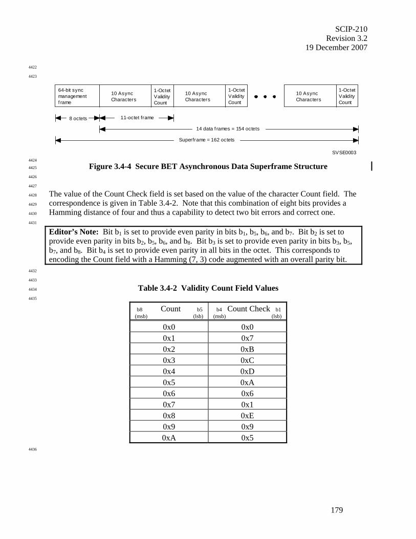
SCIP-210 Revision 3.2
19 December 2007
179
4422
4423
64-bit syncmanagementf rame
10 AsyncCharacters
1-OctetValidityCount
10 AsyncCharacters
1-OctetValidityCount
10 AsyncCharacters
1-OctetValidityCount
14 data f rames = 154 octets
Superframe = 162 octets
SVSE0003
8 octets 11-octet frame
4424
Figure 3.4-4 Secure BET Asynchronous Data Superframe Structure 4425
4426
4427
The value of the Count Check field is set based on the value of the character Count field. The 4428
correspondence is given in Table 3.4-2. Note that this combination of eight bits provides a 4429
Hamming distance of four and thus a capability to detect two bit errors and correct one. 4430
4431
Editor’s Note: Bit b1 is set to provide even parity in bits b1, b5, b6, and b7. Bit b2 is set to provide even parity in bits b2, b5, b6, and b8. Bit b3 is set to provide even parity in bits b3, b5, b7, and b8. Bit b4 is set to provide even parity in all bits in the octet. This corresponds to encoding the Count field with a Hamming (7, 3) code augmented with an overall parity bit.
4432
4433
Table 3.4-2 Validity Count Field Values 4434
4435
b8 Count b5 (msb) (lsb)
b4 Count Check b1 (msb) (lsb)
0x0 0x0 0x1 0x7 0x2 0xB 0x3 0xC 0x4 0xD 0x5 0xA 0x6 0x6 0x7 0x1 0x8 0xE 0x9 0x9 0xA 0x5
4436
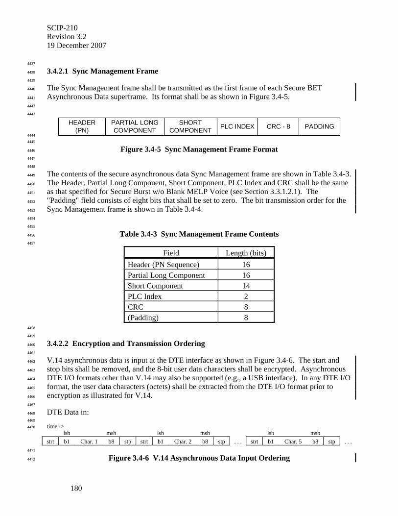
SCIP-210 Revision 3.2 19 December 2007
180
4437
3.4.2.1 Sync Management Frame 4438
4439
The Sync Management frame shall be transmitted as the first frame of each Secure BET 4440
Asynchronous Data superframe. Its format shall be as shown in Figure 3.4-5. 4441
4442
4443
HEADER(PN) PLC INDEXPARTIAL LONG
COMPONENTSHORT
COMPONENT CRC - 8 PADDING 4444
4445
Figure 3.4-5 Sync Management Frame Format 4446
4447
4448
The contents of the secure asynchronous data Sync Management frame are shown in Table 3.4-3. 4449
The Header, Partial Long Component, Short Component, PLC Index and CRC shall be the same 4450
as that specified for Secure Burst w/o Blank MELP Voice (see Section 3.3.1.2.1). The 4451
"Padding" field consists of eight bits that shall be set to zero. The bit transmission order for the 4452
Sync Management frame is shown in Table 3.4-4. 4453
4454
4455
Table 3.4-3 Sync Management Frame Contents 4456
4457
Field Length (bits) Header (PN Sequence) 16 Partial Long Component 16 Short Component 14 PLC Index 2 CRC 8 (Padding) 8
4458
4459
3.4.2.2 Encryption and Transmission Ordering 4460
4461
V.14 asynchronous data is input at the DTE interface as shown in Figure 3.4-6. The start and 4462
stop bits shall be removed, and the 8-bit user data characters shall be encrypted. Asynchronous 4463
DTE I/O formats other than V.14 may also be supported (e.g., a USB interface). In any DTE I/O 4464
format, the user data characters (octets) shall be extracted from the DTE I/O format prior to 4465
encryption as illustrated for V.14. 4466
4467
DTE Data in: 4468
4469
time -> 4470
lsb msb lsb msb lsb msb strt b1 Char. 1 b8 stp strt b1 Char. 2 b8 stp . . . strt b1 Char. 5 b8 stp . . . 4471
Figure 3.4-6 V.14 Asynchronous Data Input Ordering 4472
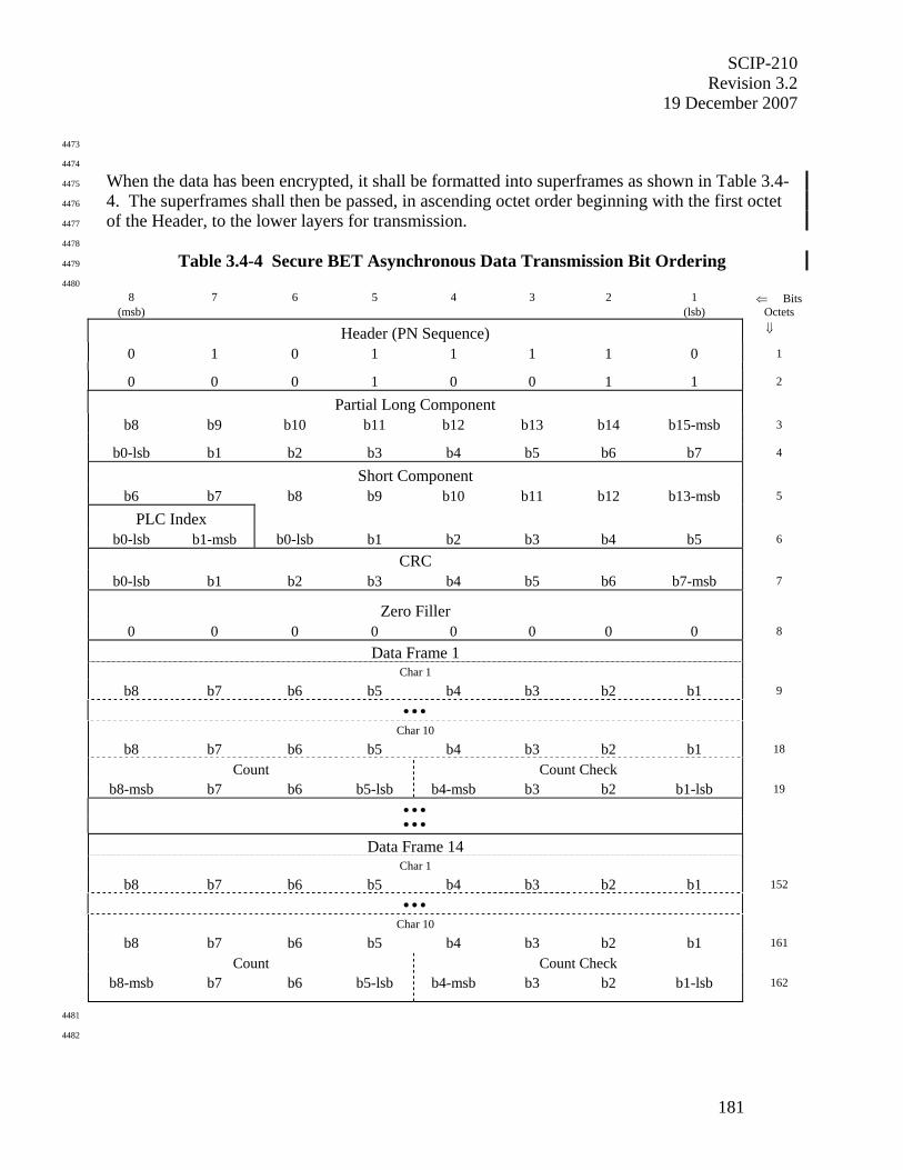
SCIP-210 Revision 3.2
19 December 2007
181
4473
4474
When the data has been encrypted, it shall be formatted into superframes as shown in Table 3.4-4475
4. The superframes shall then be passed, in ascending octet order beginning with the first octet 4476
of the Header, to the lower layers for transmission. 4477
4478
Table 3.4-4 Secure BET Asynchronous Data Transmission Bit Ordering 4479
4480 8 7 6 5 4 3 2 1 ⇐ Bits
(msb) (lsb) Octets
Header (PN Sequence) ⇓
0 1 0 1 1 1 1 0 1
0 0 0 1 0 0 1 1 2
Partial Long Component
b8 b9 b10 b11 b12 b13 b14 b15-msb 3
b0-lsb b1 b2 b3 b4 b5 b6 b7 4
Short Component b6 b7 b8 b9 b10 b11 b12 b13-msb 5
PLC Index b0-lsb b1-msb b0-lsb b1 b2 b3 b4 b5 6
CRC b0-lsb b1 b2 b3 b4 b5 b6 b7-msb 7
Zero Filler 0 0 0 0 0 0 0 0 8
Data Frame 1 Char 1
b8 b7 b6 b5 b4 b3 b2 b1 9
• • • Char 10
b8 b7 b6 b5 b4 b3 b2 b1 18
Count Count Check b8-msb b7 b6 b5-lsb b4-msb b3 b2 b1-lsb 19
• • • • • •
Data Frame 14 Char 1
b8 b7 b6 b5 b4 b3 b2 b1 152
• • • Char 10
b8 b7 b6 b5 b4 b3 b2 b1 161
Count Count Check b8-msb b7 b6 b5-lsb b4-msb b3 b2 b1-lsb 162
4481
4482

SCIP-210 Revision 3.2 19 December 2007
182
If the DTE lowers Request to Send (RTS) while the Secure BET Asynchronous Data application 4483
is active, the terminal shall complete transmission of the current superframe, filling data frame 4484
octets with 0x00 as required. If RTS remains low at the end of the superframe, the terminal shall 4485
cease transmitting. When RTS is again activated, asynchronous data transmission shall begin 4486
with a Sync Management frame followed by asynchronous data frames. 4487
4488
SCIP-210 Revision 3.2
19 December 2007
183
4489
4.0 SCIP ELECTRONIC REKEY SIGNALING 4490
4491
This section specifies the signaling required to electronically rekey the FIREFLY or ECMQV 4492
key material in SCIP terminals. In addition to providing new key material, the rekey data 4493
authenticates the SCIP terminal, and is customized to furnish organizational identification 4494
information. Compromised Key List (CKL) management is also provided as part of the 4495
Electronic Rekey function. The design approach for Electronic Rekey utilizes the Generic 4496
Rekey Front End (GRFE) to interface to the Key Processing Facility (KPF). The telephone 4497
network interface for the GRFE is provided by the SCIP Line Interface Terminal (SCIP-LIT), 4498
which establishes a secure call with the calling SCIP terminal and provides encryption for the 4499
Rekey Application Protocol Data Units (APDUs). Electronic Rekey is an independent 4500
Operational Mode in the SCIP terminal that is negotiated automatically on calls to the SCIP-LIT. 4501
4502
Editor's Note: The electronic rekey facility for ECMQV key material may be different than the one described herein for FIREFLY key material.
4503
Section 4.1 describes the SCIP Electronic Rekey protocol architecture and communication paths. 4504
Section 4.2 specifies the SCIP Message Transport layer. This is followed by an overview of the 4505
Adaptation layer and Generic Rekey Application layer in Sections 4.3 and 4.4, respectively. 4506
Detailed Electronic Rekey processing requirements are specified in SCIP-230, Section 6, or 4507
SCIP-232, Appendix E. 4508
4509
Editor's Note: The user interface for initiating rekey is left to the implementer. Options include a "Rekey" button on the terminal, programming an available speed-dialing button to dial the rekey telephone number, and simply manually dialing the rekey number. When the SCIP-LIT answers the call, it will initiate secure call setup automatically.
4510
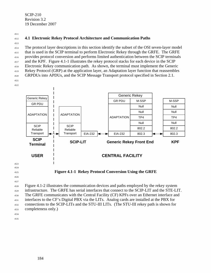
SCIP-210 Revision 3.2 19 December 2007
184
4511
4.1 Electronic Rekey Protocol Architecture and Communication Paths 4512
4513
The protocol layer descriptions in this section identify the subset of the OSI seven-layer model 4514
that is used in the SCIP terminal to perform Electronic Rekey through the GRFE. The GRFE 4515
provides protocol conversion and performs limited authentication between the SCIP terminals 4516
and the KPF. Figure 4.1-1 illustrates the rekey protocol stacks for each device in the SCIP 4517
Electronic Rekey communication path. As shown, the terminal must implement the Generic 4518
Rekey Protocol (GRP) at the application layer, an Adaptation layer function that reassembles 4519
GRPDUs into APDUs, and the SCIP Message Transport protocol specified in Section 2.1. 4520
4521
4522
M-SSP
Null
TP4
Null
802.2
802.3
GR PDU
SCIPReliable
Transport
Generic Rekey
SCIPTerminal Generic Rekey Front End KPF
M-SSP
Null
TP4
Null
802.2
802.3EIA-232
GR PDU
Generic Rekey
Null Null
ADAPTATION
EIA-232
SCIP-LIT
ADAPTATION
USER CENTRAL FACILITY
SCIPReliable
Transport
ADAPTATION
4523
4524
Figure 4.1-1 Rekey Protocol Conversion Using the GRFE 4525
4526
4527
Figure 4.1-2 illustrates the communication devices and paths employed by the rekey system 4528
infrastructure. The GRFE has serial interfaces that connect to the SCIP-LIT and the STE-LIT. 4529
The GRFE communicates with the Central Facility (CF) KPFs over an Ethernet interface and 4530
interfaces to the CF’s Digital PBX via the LITs. Analog cards are installed at the PBX for 4531
connections to the SCIP-LITs and the STU-III LITs. (The STU-III rekey path is shown for 4532
completeness only.) 4533
4534
4535
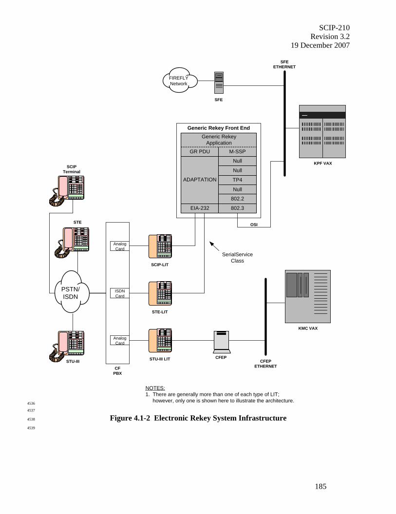
SCIP-210 Revision 3.2
19 December 2007
185
KPF VAX
FIREFLYNetwork
SFE
KMC VAX
AnalogCard
ISDNCard
AnalogCard
STU-III LIT
STE-LIT
SCIP-LIT
CFEPETHERNET
M-SSP
Null
TP4
Null
802.2
802.3
Generic Rekey Front End
EIA-232
GR PDU
Generic RekeyApplication
Null
ADAPTATION
SerialServiceClass
SFEETHERNET
CFPBX
OSI
CFEP
NOTES:1. There are generally more than one of each type of LIT; however, only one is shown here to illustrate the architecture.
PSTN/ISDN
STU-III
STE
SCIPTerminal
4536
4537
Figure 4.1-2 Electronic Rekey System Infrastructure 4538
4539
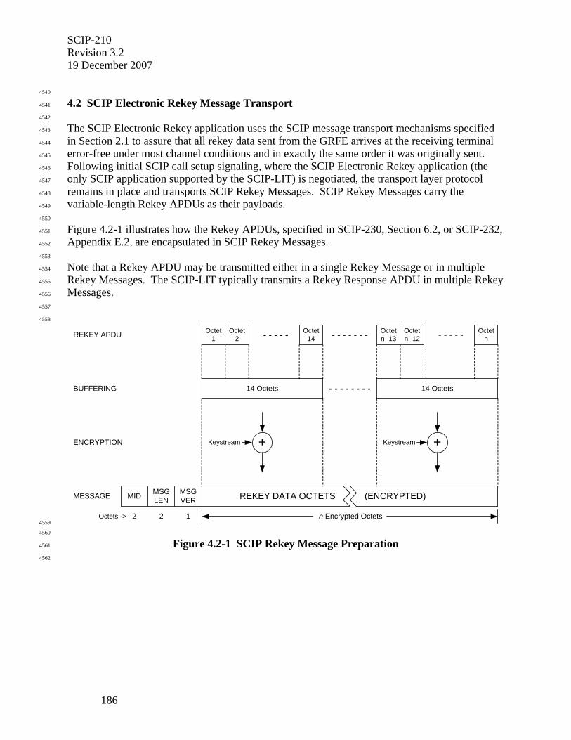
SCIP-210 Revision 3.2 19 December 2007
186
4540
4.2 SCIP Electronic Rekey Message Transport 4541
4542
The SCIP Electronic Rekey application uses the SCIP message transport mechanisms specified 4543
in Section 2.1 to assure that all rekey data sent from the GRFE arrives at the receiving terminal 4544
error-free under most channel conditions and in exactly the same order it was originally sent. 4545
Following initial SCIP call setup signaling, where the SCIP Electronic Rekey application (the 4546
only SCIP application supported by the SCIP-LIT) is negotiated, the transport layer protocol 4547
remains in place and transports SCIP Rekey Messages. SCIP Rekey Messages carry the 4548
variable-length Rekey APDUs as their payloads. 4549
4550
Figure 4.2-1 illustrates how the Rekey APDUs, specified in SCIP-230, Section 6.2, or SCIP-232, 4551
Appendix E.2, are encapsulated in SCIP Rekey Messages. 4552
4553
Note that a Rekey APDU may be transmitted either in a single Rekey Message or in multiple 4554
Rekey Messages. The SCIP-LIT typically transmits a Rekey Response APDU in multiple Rekey 4555
Messages. 4556
4557
4558
REKEY APDU
BUFFERING
ENCRYPTION
MESSAGE
Octet1
Octet2
Octet14- - - - - - - - - - - -
14 Octets 14 Octets- - - - - - - -
Octetn -13
Octetn -12
Octetn- - - - -
MID MSGLEN
MSGVER
+ +Keystream Keystream
n Encrypted Octets2 2 1Octets ->
REKEY DATA OCTETS (ENCRYPTED)
4559
4560
Figure 4.2-1 SCIP Rekey Message Preparation 4561
4562
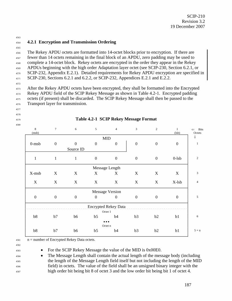
SCIP-210 Revision 3.2
19 December 2007
187
4563
4.2.1 Encryption and Transmission Ordering 4564
4565
The Rekey APDU octets are formatted into 14-octet blocks prior to encryption. If there are 4566
fewer than 14 octets remaining in the final block of an APDU, zero padding may be used to 4567
complete a 14-octet block. Rekey octets are encrypted in the order they appear in the Rekey 4568
APDUs beginning with the high order Adaptation layer octet (see SCIP-230, Section 6.2.1, or 4569
SCIP-232, Appendix E.2.1). Detailed requirements for Rekey APDU encryption are specified in 4570
SCIP-230, Sections 6.2.1 and 6.2.2, or SCIP-232, Appendices E.2.1 and E.2.2. 4571
4572
After the Rekey APDU octets have been encrypted, they shall be formatted into the Encrypted 4573
Rekey APDU field of the SCIP Rekey Message as shown in Table 4.2-1. Encrypted padding 4574
octets (if present) shall be discarded. The SCIP Rekey Message shall then be passed to the 4575
Transport layer for transmission. 4576
4577
4578
Table 4.2-1 SCIP Rekey Message Format 4579
4580
8 7 6 5 4 3 2 1 ⇐ Bits (msb) (lsb) Octets
MID ⇓
0-msb 0 0 0 0 0 0 0 1
Source ID
1 1 1 0 0 0 0 0-lsb 2
Message Length X-msb X X X X X X X 3
X X X X X X X X-lsb 4
Message Version 0 0 0 0 0 0 0 0 5
Encrypted Rekey Data Octet 1
b8 b7 b6 b5 b4 b3 b2 b1 6
• • •
Octet n
b8 b7 b6 b5 b4 b3 b2 b1 5 + n
n = number of Encrypted Rekey Data octets. 4581
4582
• For the SCIP Rekey Message the value of the MID is 0x00E0. 4583
• The Message Length shall contain the actual length of the message body (including 4584
the length of the Message Length field itself but not including the length of the MID 4585
field) in octets. The value of the field shall be an unsigned binary integer with the 4586
high order bit being bit 8 of octet 3 and the low order bit being bit 1 of octet 4. 4587
SCIP-210 Revision 3.2 19 December 2007
188
• For the version of the SCIP Rekey Message defined in this version of the Signaling 4588
Plan, the value of the Message Version field is 0x00. 4589
• The Encrypted Rekey Data field contains a variable number of octets that correspond 4590
to an encrypted Rekey APDU or partial APDU. The msb of the high order 4591
Adaptation layer octet of the encrypted APDU (as defined in SCIP-230, Section 4592
6.2.1, or SCIP-232, Appendix E.2.1) shall be placed in bit 8 of octet 1 of the first 4593
Rekey Message. 4594
4595
4596
4.2.2 SCIP Rekey Message Transmission 4597
4598
SCIP Rekey Messages are constructed at the SCIP-LIT or the destination terminal, depending on 4599
the direction the message will travel. The SCIP-LIT or the destination terminal shall then use 4600
the processes described in Section 2.1, including SOM/EOM framing, frame counters, CRC, 4601
FEC, and ACK/NAK using REPORT Messages, to transmit the SCIP Rekey Message to the 4602
destination terminal or to the SCIP-LIT. The message shall be transmitted in ascending octet 4603
order. 4604
4605
4606
4.2.3 SCIP Rekey Message Reception 4607
4608
Following the transition from call setup signaling to SCIP Rekey, the receiving terminal’s 4609
Transport layer shall continue to monitor the communications channel searching for incoming 4610
SOM patterns and the associated transport frames as described in Section 2.1.6. Payload data 4611
from the transport frames shall be transferred to the message layer, where SCIP Rekey Messages 4612
shall be verified and interpreted. 4613
4614
Information extracted from the Encrypted Rekey Data field of each received SCIP Rekey 4615
Message shall be decrypted in the order shown in Figure 4.2-2 and passed to the Adaptation 4616
layer described in Section 4.3. 4617
4618
The terminal shall wait at least 10 seconds after call setup is complete before transmitting a 4619
Rekey Request Message (Grkrq) to the SCIP-LIT. This is required to accommodate the SCIP-4620
LIT processing delay. 4621
4622
SCIP-210 Revision 3.2
19 December 2007
189
4623
4.3 Adaptation Layer 4624
4625
The Adaptation layer, which resides between the Generic Rekey Application layer and the SCIP 4626
Reliable Transport layer, is used to convey application PDU length information and to 4627
reassemble application PDUs from the received Rekey data. On the transmit side, a two-octet 4628
length field is appended to the front of each Generic Rekey PDU (GRPDU) indicating the 4629
number of octets in the PDU (not including the appended length field). If Rekey Option 0x0006 4630
(with 32-bit CRC) was negotiated, the CRC check bits are also computed and appended to the 4631
end of the GRPDU. The resulting Rekey APDU, comprised of the GRPDU and the appended 4632
length field (and CRC, if this option was negotiated), is encrypted and then transmitted using the 4633
SCIP Reliable Transport. On the receive side, the decrypted Rekey APDU is passed to the 4634
Adaptation layer, which extracts and examines the two-octet length field to determine the 4635
number of octets in the application PDU to be reconstructed (and verifies the CRC, if this option 4636
was negotiated). 4637
4638
If Rekey Option 0x0006 (with 32-bit CRC) was negotiated and the CRC verification fails at the 4639
SCIP-LIT, the SCIP-LIT shall terminate the call by transmitting a Notification Message with the 4640
Action set to Connection Terminate and the Information Code set to Rekey Message CRC 4641
failure. If the CRC verification fails at the terminal being rekeyed, the terminal shall proceed 4642
with one of the options specified in SCIP-230, Section 6.2.1, or SCIP-232, Appendix E.2.1. 4643
4644
Further details of the Adaptation layer are specified in SCIP-230, Section 6.2.1, or SCIP-232, 4645
Appendix E.2.1. 4646
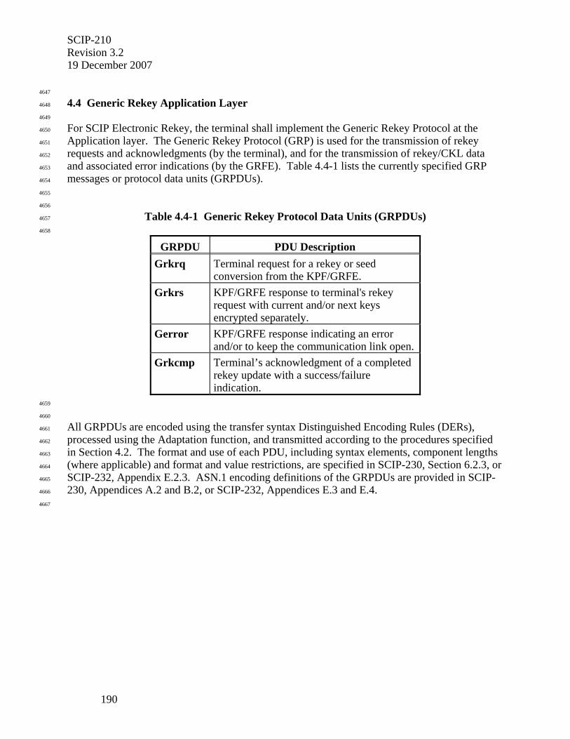
SCIP-210 Revision 3.2 19 December 2007
190
4647
4.4 Generic Rekey Application Layer 4648
4649
For SCIP Electronic Rekey, the terminal shall implement the Generic Rekey Protocol at the 4650
Application layer. The Generic Rekey Protocol (GRP) is used for the transmission of rekey 4651
requests and acknowledgments (by the terminal), and for the transmission of rekey/CKL data 4652
and associated error indications (by the GRFE). Table 4.4-1 lists the currently specified GRP 4653
messages or protocol data units (GRPDUs). 4654
4655
4656
Table 4.4-1 Generic Rekey Protocol Data Units (GRPDUs) 4657
4658
GRPDU PDU Description Grkrq Terminal request for a rekey or seed
conversion from the KPF/GRFE. Grkrs KPF/GRFE response to terminal's rekey
request with current and/or next keys encrypted separately.
Gerror KPF/GRFE response indicating an error and/or to keep the communication link open.
Grkcmp Terminal’s acknowledgment of a completed rekey update with a success/failure indication.
4659
4660
All GRPDUs are encoded using the transfer syntax Distinguished Encoding Rules (DERs), 4661
processed using the Adaptation function, and transmitted according to the procedures specified 4662
in Section 4.2. The format and use of each PDU, including syntax elements, component lengths 4663
(where applicable) and format and value restrictions, are specified in SCIP-230, Section 6.2.3, or 4664
SCIP-232, Appendix E.2.3. ASN.1 encoding definitions of the GRPDUs are provided in SCIP-4665
230, Appendices A.2 and B.2, or SCIP-232, Appendices E.3 and E.4. 4666
4667
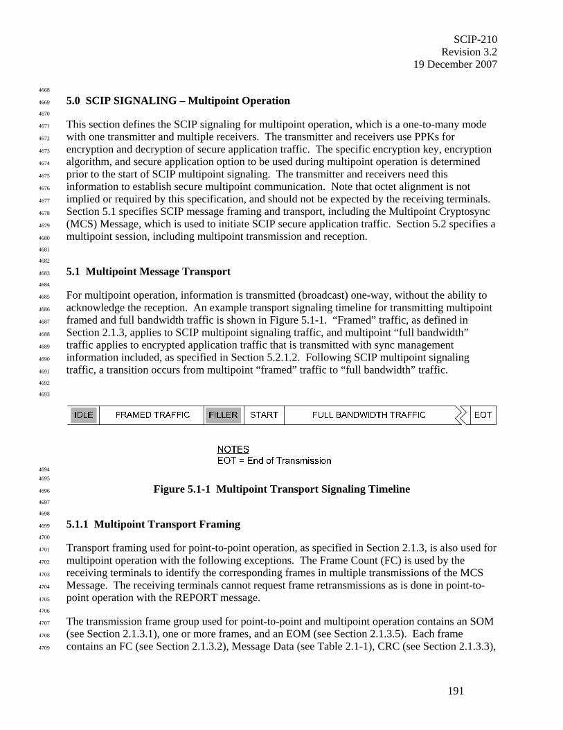
SCIP-210 Revision 3.2
19 December 2007
191
4668
5.0 SCIP SIGNALING – Multipoint Operation 4669
4670
This section defines the SCIP signaling for multipoint operation, which is a one-to-many mode 4671
with one transmitter and multiple receivers. The transmitter and receivers use PPKs for 4672
encryption and decryption of secure application traffic. The specific encryption key, encryption 4673
algorithm, and secure application option to be used during multipoint operation is determined 4674
prior to the start of SCIP multipoint signaling. The transmitter and receivers need this 4675
information to establish secure multipoint communication. Note that octet alignment is not 4676
implied or required by this specification, and should not be expected by the receiving terminals. 4677
Section 5.1 specifies SCIP message framing and transport, including the Multipoint Cryptosync 4678
(MCS) Message, which is used to initiate SCIP secure application traffic. Section 5.2 specifies a 4679
multipoint session, including multipoint transmission and reception. 4680
4681
4682
5.1 Multipoint Message Transport 4683
4684
For multipoint operation, information is transmitted (broadcast) one-way, without the ability to 4685
acknowledge the reception. An example transport signaling timeline for transmitting multipoint 4686
framed and full bandwidth traffic is shown in Figure 5.1-1. “Framed” traffic, as defined in 4687
Section 2.1.3, applies to SCIP multipoint signaling traffic, and multipoint “full bandwidth” 4688
traffic applies to encrypted application traffic that is transmitted with sync management 4689
information included, as specified in Section 5.2.1.2. Following SCIP multipoint signaling 4690
traffic, a transition occurs from multipoint “framed” traffic to “full bandwidth” traffic. 4691
4692
4693
4694 4695
Figure 5.1-1 Multipoint Transport Signaling Timeline 4696
4697
4698
5.1.1 Multipoint Transport Framing 4699
4700
Transport framing used for point-to-point operation, as specified in Section 2.1.3, is also used for 4701
multipoint operation with the following exceptions. The Frame Count (FC) is used by the 4702
receiving terminals to identify the corresponding frames in multiple transmissions of the MCS 4703
Message. The receiving terminals cannot request frame retransmissions as is done in point-to-4704
point operation with the REPORT message. 4705
4706
The transmission frame group used for point-to-point and multipoint operation contains an SOM 4707
(see Section 2.1.3.1), one or more frames, and an EOM (see Section 2.1.3.5). Each frame 4708
contains an FC (see Section 2.1.3.2), Message Data (see Table 2.1-1), CRC (see Section 2.1.3.3), 4709
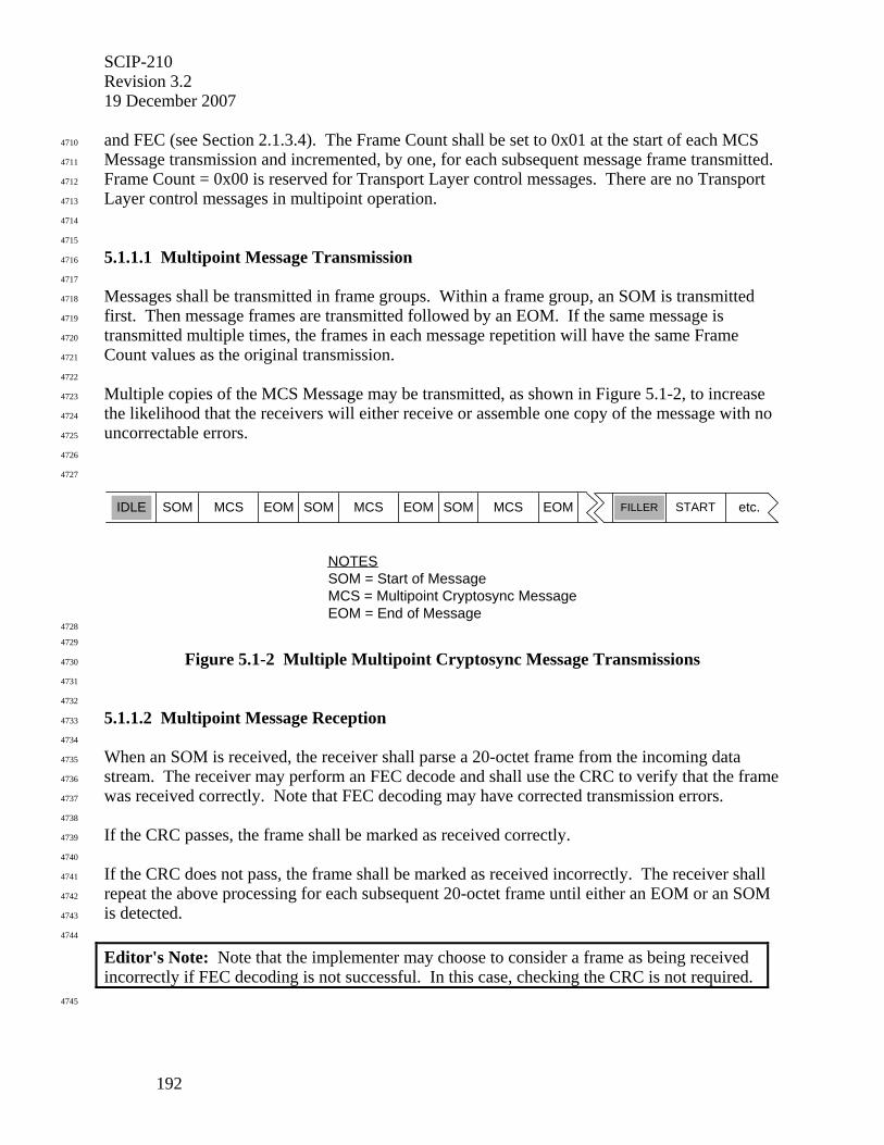
SCIP-210 Revision 3.2 19 December 2007
192
and FEC (see Section 2.1.3.4). The Frame Count shall be set to 0x01 at the start of each MCS 4710
Message transmission and incremented, by one, for each subsequent message frame transmitted. 4711
Frame Count = 0x00 is reserved for Transport Layer control messages. There are no Transport 4712
Layer control messages in multipoint operation. 4713
4714
4715
5.1.1.1 Multipoint Message Transmission 4716
4717
Messages shall be transmitted in frame groups. Within a frame group, an SOM is transmitted 4718
first. Then message frames are transmitted followed by an EOM. If the same message is 4719
transmitted multiple times, the frames in each message repetition will have the same Frame 4720
Count values as the original transmission. 4721
4722
Multiple copies of the MCS Message may be transmitted, as shown in Figure 5.1-2, to increase 4723
the likelihood that the receivers will either receive or assemble one copy of the message with no 4724
uncorrectable errors. 4725
4726
4727
MCS etc.IDLE FILLER
NOTESSOM = Start of MessageMCS = Multipoint Cryptosync MessageEOM = End of Message
SOM EOM MCSSOM EOM MCSSOM EOM START
4728
4729
Figure 5.1-2 Multiple Multipoint Cryptosync Message Transmissions 4730
4731
4732
5.1.1.2 Multipoint Message Reception 4733
4734
When an SOM is received, the receiver shall parse a 20-octet frame from the incoming data 4735
stream. The receiver may perform an FEC decode and shall use the CRC to verify that the frame 4736
was received correctly. Note that FEC decoding may have corrected transmission errors. 4737
4738
If the CRC passes, the frame shall be marked as received correctly. 4739
4740
If the CRC does not pass, the frame shall be marked as received incorrectly. The receiver shall 4741
repeat the above processing for each subsequent 20-octet frame until either an EOM or an SOM 4742
is detected. 4743
4744
Editor's Note: Note that the implementer may choose to consider a frame as being received incorrectly if FEC decoding is not successful. In this case, checking the CRC is not required.
4745
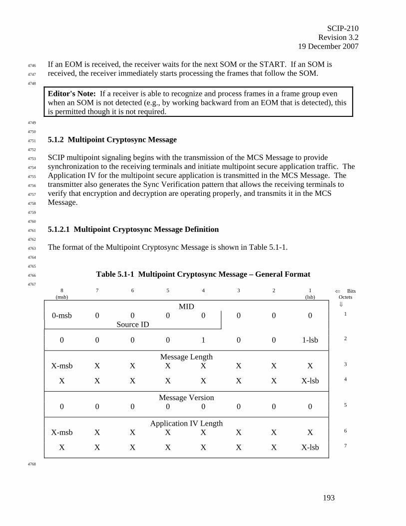
SCIP-210 Revision 3.2
19 December 2007
193
If an EOM is received, the receiver waits for the next SOM or the START. If an SOM is 4746
received, the receiver immediately starts processing the frames that follow the SOM. 4747
4748
Editor's Note: If a receiver is able to recognize and process frames in a frame group even when an SOM is not detected (e.g., by working backward from an EOM that is detected), this is permitted though it is not required.
4749
4750
5.1.2 Multipoint Cryptosync Message 4751
4752
SCIP multipoint signaling begins with the transmission of the MCS Message to provide 4753
synchronization to the receiving terminals and initiate multipoint secure application traffic. The 4754
Application IV for the multipoint secure application is transmitted in the MCS Message. The 4755
transmitter also generates the Sync Verification pattern that allows the receiving terminals to 4756
verify that encryption and decryption are operating properly, and transmits it in the MCS 4757
Message. 4758
4759
4760
5.1.2.1 Multipoint Cryptosync Message Definition 4761
4762
The format of the Multipoint Cryptosync Message is shown in Table 5.1-1. 4763
4764
4765
Table 5.1-1 Multipoint Cryptosync Message – General Format 4766
4767 8 7 6 5 4 3 2 1 ⇐ Bits
(msb) (lsb) Octets
MID ⇓
0-msb 0 0 0 0 0 0 0 1
Source ID
0 0 0 0 1 0 0 1-lsb 2
Message Length
X-msb X X X X X X X 3
X X X X X X X X-lsb 4
Message Version
0 0 0 0 0 0 0 0 5
Application IV Length
X-msb X X X X X X X 6
X X X X X X X X-lsb 7
4768
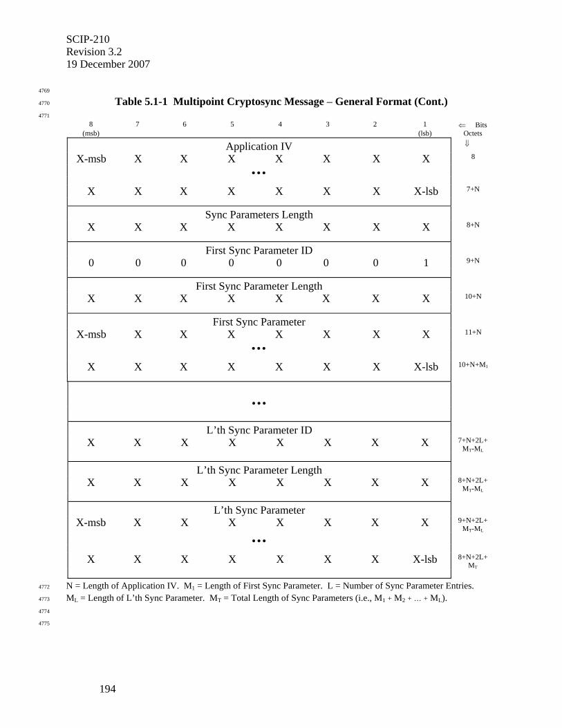
SCIP-210 Revision 3.2 19 December 2007
194
4769
Table 5.1-1 Multipoint Cryptosync Message – General Format (Cont.) 4770
4771 8 7 6 5 4 3 2 1 ⇐ Bits
(msb) (lsb) Octets
Application IV ⇓
X-msb X X X X X X X 8
• • •
X X X X X X X X-lsb 7+N
Sync Parameters Length
X X X X X X X X 8+N
First Sync Parameter ID
0 0 0 0 0 0 0 1 9+N
First Sync Parameter Length
X X X X X X X X 10+N
First Sync Parameter
X-msb X X X X X X X 11+N
• • •
X X X X X X X X-lsb 10+N+M1
• • •
L’th Sync Parameter ID
X X X X X X X X 7+N+2L+MT-ML
L’th Sync Parameter Length
X X X X X X X X 8+N+2L+MT-ML
L’th Sync Parameter
X-msb X X X X X X X 9+N+2L+MT-ML
• • •
X X X X X X X X-lsb 8+N+2L+MT
N = Length of Application IV. M1 = Length of First Sync Parameter. L = Number of Sync Parameter Entries. 4772
ML = Length of L’th Sync Parameter. MT = Total Length of Sync Parameters (i.e., M1 + M2 + … + ML). 4773
4774
4775
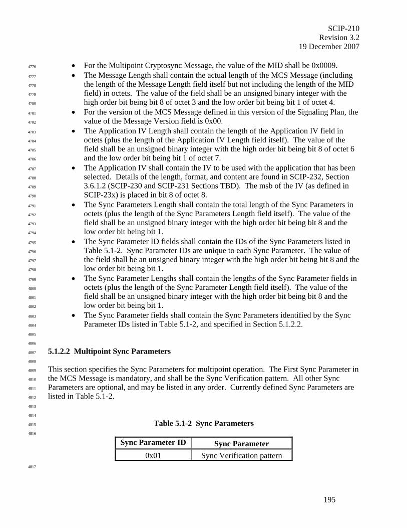
SCIP-210 Revision 3.2
19 December 2007
195
• For the Multipoint Cryptosync Message, the value of the MID shall be 0x0009. 4776
• The Message Length shall contain the actual length of the MCS Message (including 4777
the length of the Message Length field itself but not including the length of the MID 4778
field) in octets. The value of the field shall be an unsigned binary integer with the 4779
high order bit being bit 8 of octet 3 and the low order bit being bit 1 of octet 4. 4780
• For the version of the MCS Message defined in this version of the Signaling Plan, the 4781
value of the Message Version field is 0x00. 4782
• The Application IV Length shall contain the length of the Application IV field in 4783
octets (plus the length of the Application IV Length field itself). The value of the 4784
field shall be an unsigned binary integer with the high order bit being bit 8 of octet 6 4785
and the low order bit being bit 1 of octet 7. 4786
• The Application IV shall contain the IV to be used with the application that has been 4787
selected. Details of the length, format, and content are found in SCIP-232, Section 4788
3.6.1.2 (SCIP-230 and SCIP-231 Sections TBD). The msb of the IV (as defined in 4789
SCIP-23x) is placed in bit 8 of octet 8. 4790
• The Sync Parameters Length shall contain the total length of the Sync Parameters in 4791
octets (plus the length of the Sync Parameters Length field itself). The value of the 4792
field shall be an unsigned binary integer with the high order bit being bit 8 and the 4793
low order bit being bit 1. 4794
• The Sync Parameter ID fields shall contain the IDs of the Sync Parameters listed in 4795
Table 5.1-2. Sync Parameter IDs are unique to each Sync Parameter. The value of 4796
the field shall be an unsigned binary integer with the high order bit being bit 8 and the 4797
low order bit being bit 1. 4798
• The Sync Parameter Lengths shall contain the lengths of the Sync Parameter fields in 4799
octets (plus the length of the Sync Parameter Length field itself). The value of the 4800
field shall be an unsigned binary integer with the high order bit being bit 8 and the 4801
low order bit being bit 1. 4802
• The Sync Parameter fields shall contain the Sync Parameters identified by the Sync 4803
Parameter IDs listed in Table 5.1-2, and specified in Section 5.1.2.2. 4804
4805
4806
5.1.2.2 Multipoint Sync Parameters 4807
4808
This section specifies the Sync Parameters for multipoint operation. The First Sync Parameter in 4809
the MCS Message is mandatory, and shall be the Sync Verification pattern. All other Sync 4810
Parameters are optional, and may be listed in any order. Currently defined Sync Parameters are 4811
listed in Table 5.1-2. 4812
4813
4814
Table 5.1-2 Sync Parameters 4815
4816
Sync Parameter ID Sync Parameter 0x01 Sync Verification pattern
4817
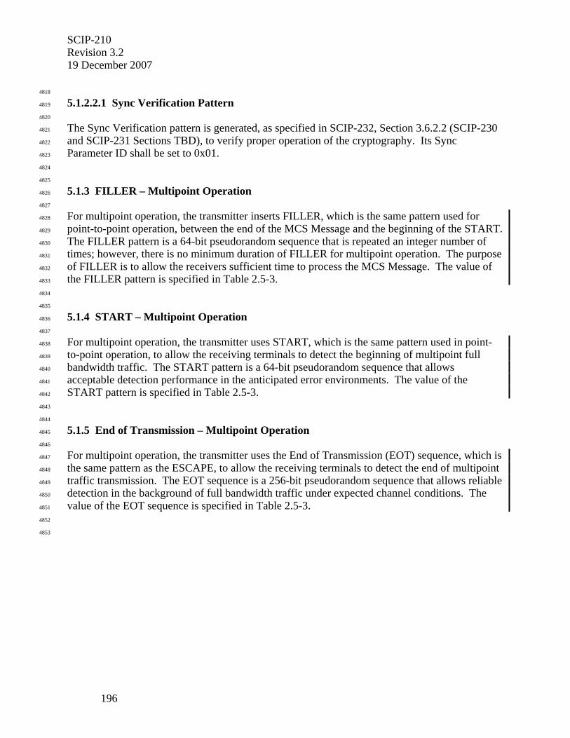
SCIP-210 Revision 3.2 19 December 2007
196
4818
5.1.2.2.1 Sync Verification Pattern 4819
4820
The Sync Verification pattern is generated, as specified in SCIP-232, Section 3.6.2.2 (SCIP-230 4821
and SCIP-231 Sections TBD), to verify proper operation of the cryptography. Its Sync 4822
Parameter ID shall be set to 0x01. 4823
4824
4825
5.1.3 FILLER – Multipoint Operation 4826
4827
For multipoint operation, the transmitter inserts FILLER, which is the same pattern used for 4828
point-to-point operation, between the end of the MCS Message and the beginning of the START. 4829
The FILLER pattern is a 64-bit pseudorandom sequence that is repeated an integer number of 4830
times; however, there is no minimum duration of FILLER for multipoint operation. The purpose 4831
of FILLER is to allow the receivers sufficient time to process the MCS Message. The value of 4832
the FILLER pattern is specified in Table 2.5-3. 4833
4834
4835
5.1.4 START – Multipoint Operation 4836
4837
For multipoint operation, the transmitter uses START, which is the same pattern used in point-4838
to-point operation, to allow the receiving terminals to detect the beginning of multipoint full 4839
bandwidth traffic. The START pattern is a 64-bit pseudorandom sequence that allows 4840
acceptable detection performance in the anticipated error environments. The value of the 4841
START pattern is specified in Table 2.5-3. 4842
4843
4844
5.1.5 End of Transmission – Multipoint Operation 4845
4846
For multipoint operation, the transmitter uses the End of Transmission (EOT) sequence, which is 4847
the same pattern as the ESCAPE, to allow the receiving terminals to detect the end of multipoint 4848
traffic transmission. The EOT sequence is a 256-bit pseudorandom sequence that allows reliable 4849
detection in the background of full bandwidth traffic under expected channel conditions. The 4850
value of the EOT sequence is specified in Table 2.5-3. 4851
4852
4853
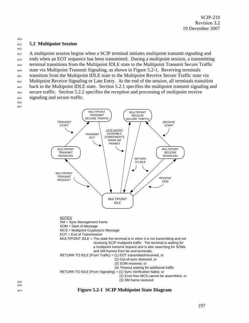
SCIP-210 Revision 3.2
19 December 2007
197
4854
5.2 Multipoint Session 4855
4856
A multipoint session begins when a SCIP terminal initiates multipoint transmit signaling and 4857
ends when an EOT sequence has been transmitted. During a multipoint session, a transmitting 4858
terminal transitions from the Multipoint IDLE state to the Multipoint Transmit Secure Traffic 4859
state via Multipoint Transmit Signaling, as shown in Figure 5.2-1. Receiving terminals 4860
transition from the Multipoint IDLE state to the Multipoint Receive Secure Traffic state via 4861
Multipoint Receive Signaling or Late Entry. At the end of the session, all terminals transition 4862
back to the Multipoint IDLE state. Section 5.2.1 specifies the multipoint transmit signaling and 4863
secure traffic. Section 5.2.2 specifies the reception and processing of multipoint receive 4864
signaling and secure traffic. 4865
4866
4867
MULTIPOINTIDLE
RETURNTO IDLE
MULTIPOINTTRANSMITREQUEST
RECEIVESOM
MULTIPOINTTRANSMITSIGNALING
MULTIPOINTRECEIVE
SECURE TRAFFIC
MULTIPOINTTRANSMIT
SECURE TRAFFICTRANSMIT
START
MULTIPOINTRECEIVE
SIGNALING
TRANSMITEOT
RECEIVESTART
NOTESSM = Sync Management frameSOM = Start of MessageMCS = Multipoint Cryptosync MessageEOT = End of TransmissionMULTIPOINT IDLE = The state the terminal is in when it is not transmitting and not receiving SCIP multipoint traffic. The terminal is waiting for
a multipoint transmit request and is also searching for SOMs and SM frames from far-end terminals.RETURN TO IDLE (From Traffic) = (1) EOT transmitted/received, or (2) Out-of-sync detected, or (3) SOM received, or (4) Timeout waiting for additional trafficRETURN TO IDLE (From Signaling) = (1) Sync Verification failed, or (2) Error-free MCS cannot be assembled, or (3) SM frame received
LATE ENTRYASSEMBLE
COMPONENTSFROM SMFRAMES
4868 4869
Figure 5.2-1 SCIP Multipoint State Diagram 4870
SCIP-210 Revision 3.2 19 December 2007
198
4871
5.2.1 Multipoint Transmission 4872
4873
This section specifies SCIP multipoint transmission. It is assumed that a point-to-multipoint 4874
digital channel has already been established, using the underlying channel protocols, by means 4875
outside the scope of this Signaling Plan. The signaling necessary to establish a SCIP multipoint 4876
secure application is then executed over this digital channel. The SCIP terminal transmits the 4877
signaling specified in this section to the receiving SCIP terminals to establish the multipoint 4878
session. 4879
4880
An example of the overall flow for SCIP multipoint transmit signaling is shown in Figure 5.2-2. 4881
During Multipoint IDLE periods, there is no transmission by the SCIP application, though there 4882
may actually be transmissions on individual links related to signaling performed by the 4883
underlying digital channel protocols. Multipoint IDLE periods are permitted at any time. SCIP 4884
multipoint transmit signaling shall begin with the transmission of the MCS Message, as specified 4885
in Section 5.2.1.1. If FILLER is transmitted, the pattern shall be sent an integer number of 4886
repetitions and follow the MCS Message transmission. START shall follow FILLER, if FILLER 4887
is transmitted. Otherwise, START shall follow the MCS Message transmission. Transmission 4888
of the START shall precede multipoint full bandwidth TRAFFIC. The transmission of 4889
multipoint secure traffic is specified in Section 5.2.1.2. The EOT sequence shall follow 4890
multipoint full bandwidth TRAFFIC. The end of multipoint secure traffic transmission is 4891
specified in Section 5.2.1.3. The MCS Message format and FILLER, START, and EOT patterns 4892
are specified in Section 5.1. 4893
4894
4895
4896
4897
Figure 5.2-2 Multipoint Secure Voice Transmit Signaling Time Line 4898
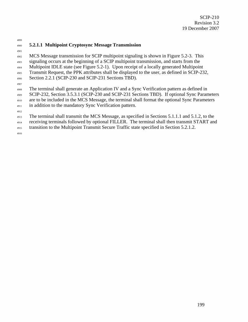
SCIP-210 Revision 3.2
19 December 2007
199
4899
5.2.1.1 Multipoint Cryptosync Message Transmission 4900
4901
MCS Message transmission for SCIP multipoint signaling is shown in Figure 5.2-3. This 4902
signaling occurs at the beginning of a SCIP multipoint transmission, and starts from the 4903
Multipoint IDLE state (see Figure 5.2-1). Upon receipt of a locally generated Multipoint 4904
Transmit Request, the PPK attributes shall be displayed to the user, as defined in SCIP-232, 4905
Section 2.2.1 (SCIP-230 and SCIP-231 Sections TBD). 4906
4907
The terminal shall generate an Application IV and a Sync Verification pattern as defined in 4908
SCIP-232, Section 3.5.3.1 (SCIP-230 and SCIP-231 Sections TBD). If optional Sync Parameters 4909
are to be included in the MCS Message, the terminal shall format the optional Sync Parameters 4910
in addition to the mandatory Sync Verification pattern. 4911
4912
The terminal shall transmit the MCS Message, as specified in Sections 5.1.1.1 and 5.1.2, to the 4913
receiving terminals followed by optional FILLER. The terminal shall then transmit START and 4914
transition to the Multipoint Transmit Secure Traffic state specified in Section 5.2.1.2. 4915
4916
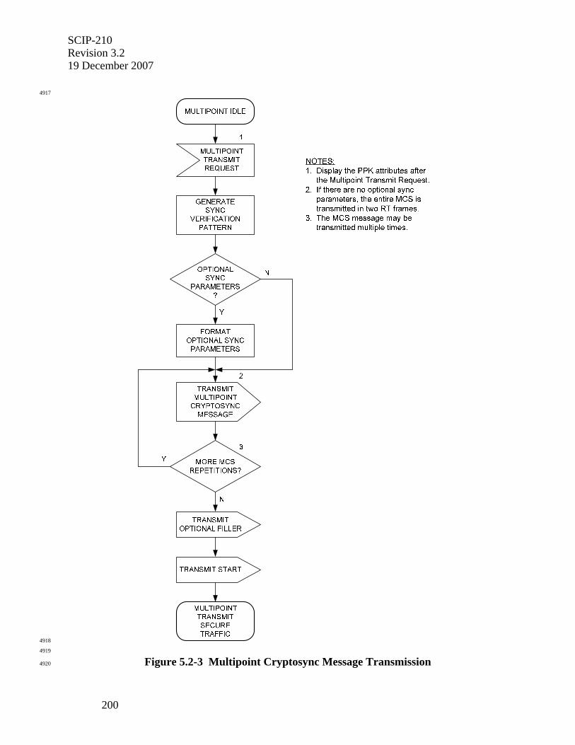
SCIP-210 Revision 3.2 19 December 2007
200
4917
4918
4919
Figure 5.2-3 Multipoint Cryptosync Message Transmission 4920
SCIP-210 Revision 3.2
19 December 2007
201
4921
5.2.1.2 Multipoint Secure Traffic Transmission 4922
4923
Multipoint secure traffic transmission processing, using the Application IV included in the MCS 4924
Message, shall begin after the terminal transitions to the Multipoint Transmit Secure Traffic state 4925
(see Figure 5.2-1). The Secure MELP Voice application is specified in Section 5.2.1.2.1 for 4926
multipoint secure traffic transmission. The Secure G.729D Voice (see Section 5.2.1.2.2) and 4927
Secure Data (see Section 5.2.1.2.3) applications are TBSL. 4928
4929
4930
5.2.1.2.1 Multipoint Secure MELP Voice Transmission 4931
4932
Secure 2400 bps Blank and Burst MELP Voice with FCT is used for multipoint operation. A 4933
Sync Management frame is substituted periodically for a vocoder frame. The vocoder frame that 4934
would normally have been transmitted during the Sync Management frame transmission interval 4935
is discarded. The Sync Management frame contains information that allows late-entry 4936
cryptographic synchronization as well as cryptographic synchronization maintenance. The 4937
MELP vocoder is run continuously, and all frames that are generated (excluding blanked frames) 4938
are transmitted. DTX operation (see Section 3.3.1.4) is not supported for multipoint operation. 4939
4940
Secure 2400 bps Blank and Burst MELP Voice shall be transmitted in a "superframe" consisting 4941
of a 54-bit Sync Management frame followed by 23 54-bit MELP vocoder frames, except when 4942
shortened by the transmission of an EOT to end multipoint traffic transmission. The contents of 4943
the 54-bit MELP vocoder frame, representing 22.5 msec. of speech, shall be as specified in MIL-4944
STD-3005 or NATO STANAG 4591. The MELP encryption and transmission bit ordering shall 4945
be the same as for point-to-point operation. The alternating 1/0 sync bit in the first MELP 4946
vocoder frame transmitted may have either value, and the receiver must be prepared to accept 4947
either value. 4948
4949
An example of multipoint Secure 2400 bps Blank and Burst MELP Voice transmission is shown 4950
in Figure 5.2-4. Secure traffic shall begin with a START and end with an EOT. MELP and 4951
Sync Management frames shall be transmitted between the START and EOT. Note that the 4952
superframe always begins with a Sync Management frame. Note also that the first vocoder 4953
frame shall be discarded (blanked) and replaced by a Sync Management frame. In all cases, 4954
however, the first MELP frame actually transmitted in a superframe is encrypted using the 4955
second half of the first state vector value for that superframe. 4956
4957
4958
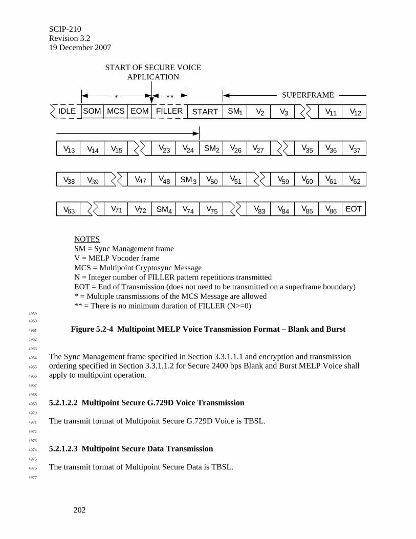
SCIP-210 Revision 3.2 19 December 2007
202
SOM MCS EOM FILLER START SM1 V2 V3 V11 V12
V13 V14 V15 V23 V24 SM2 V26 V27 V35 V36 V37
V38 V39 V48 V50 SM3 V51 V59 V60 V61 V62 V47
V63 V71 V74 V75 SM4 V83 V84 V85 V86 EOT V72
START OF SECURE VOICEAPPLICATION
SUPERFRAME*
IDLE
NOTESSM = Sync Management frameV = MELP Vocoder frameMCS = Multipoint Cryptosync MessageN = Integer number of FILLER pattern repetitions transmittedEOT = End of Transmission (does not need to be transmitted on a superframe boundary)* = Multiple transmissions of the MCS Message are allowed** = There is no minimum duration of FILLER (N>=0)
**
4959
4960
Figure 5.2-4 Multipoint MELP Voice Transmission Format – Blank and Burst 4961
4962
4963
The Sync Management frame specified in Section 3.3.1.1.1 and encryption and transmission 4964
ordering specified in Section 3.3.1.1.2 for Secure 2400 bps Blank and Burst MELP Voice shall 4965
apply to multipoint operation. 4966
4967
4968
5.2.1.2.2 Multipoint Secure G.729D Voice Transmission 4969
4970
The transmit format of Multipoint Secure G.729D Voice is TBSL. 4971
4972
4973
5.2.1.2.3 Multipoint Secure Data Transmission 4974
4975
The transmit format of Multipoint Secure Data is TBSL. 4976
4977
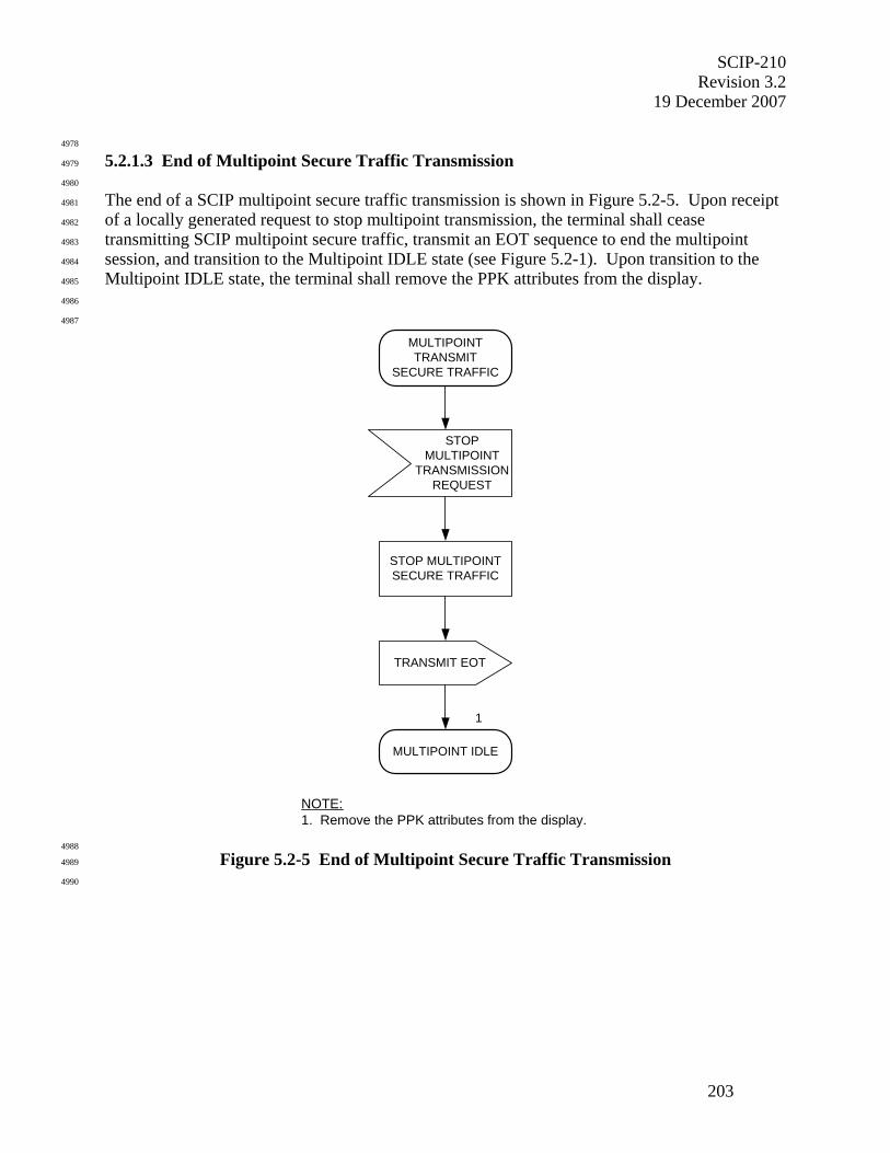
SCIP-210 Revision 3.2
19 December 2007
203
4978
5.2.1.3 End of Multipoint Secure Traffic Transmission 4979
4980
The end of a SCIP multipoint secure traffic transmission is shown in Figure 5.2-5. Upon receipt 4981
of a locally generated request to stop multipoint transmission, the terminal shall cease 4982
transmitting SCIP multipoint secure traffic, transmit an EOT sequence to end the multipoint 4983
session, and transition to the Multipoint IDLE state (see Figure 5.2-1). Upon transition to the 4984
Multipoint IDLE state, the terminal shall remove the PPK attributes from the display. 4985
4986
4987
STOPMULTIPOINT
TRANSMISSIONREQUEST
MULTIPOINTTRANSMIT
SECURE TRAFFIC
TRANSMIT EOT
MULTIPOINT IDLE
STOP MULTIPOINTSECURE TRAFFIC
NOTE:1. Remove the PPK attributes from the display.
1
4988
Figure 5.2-5 End of Multipoint Secure Traffic Transmission 4989
4990
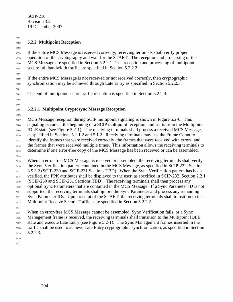
SCIP-210 Revision 3.2 19 December 2007
204
4991
5.2.2 Multipoint Reception 4992
4993
If the entire MCS Message is received correctly, receiving terminals shall verify proper 4994
operation of the cryptography and wait for the START. The reception and processing of the 4995
MCS Message are specified in Section 5.2.2.1. The reception and processing of multipoint 4996
secure full bandwidth traffic are specified in Section 5.2.2.2. 4997
4998
If the entire MCS Message is not received or not received correctly, then cryptographic 4999
synchronization may be achieved through Late Entry as specified in Section 5.2.2.3. 5000
5001
The end of multipoint secure traffic reception is specified in Section 5.2.2.4. 5002
5003
5004
5.2.2.1 Multipoint Cryptosync Message Reception 5005
5006
MCS Message reception during SCIP multipoint signaling is shown in Figure 5.2-6. This 5007
signaling occurs at the beginning of a SCIP multipoint reception, and starts from the Multipoint 5008
IDLE state (see Figure 5.2-1). The receiving terminals shall process a received MCS Message, 5009
as specified in Sections 5.1.1.2 and 5.1.2. Receiving terminals may use the Frame Count to 5010
identify the frames that were received correctly, the frames that were received with errors, and 5011
the frames that were received multiple times. This information allows the receiving terminals to 5012
determine if one error-free copy of the MCS Message has been received or can be assembled. 5013
5014
When an error-free MCS Message is received or assembled, the receiving terminals shall verify 5015
the Sync Verification pattern contained in the MCS Message, as specified in SCIP-232, Section 5016
3.5.3.2 (SCIP-230 and SCIP-231 Sections TBD). When the Sync Verification pattern has been 5017
verified, the PPK attributes shall be displayed to the user, as specified in SCIP-232, Section 2.2.1 5018
(SCIP-230 and SCIP-231 Sections TBD). The receiving terminals shall then process any 5019
optional Sync Parameters that are contained in the MCS Message. If a Sync Parameter ID is not 5020
supported, the receiving terminals shall ignore the Sync Parameter and process any remaining 5021
Sync Parameter IDs. Upon receipt of the START, the receiving terminals shall transition to the 5022
Multipoint Receive Secure Traffic state specified in Section 5.2.2.2. 5023
5024
When an error-free MCS Message cannot be assembled, Sync Verification fails, or a Sync 5025
Management frame is received, the receiving terminals shall transition to the Multipoint IDLE 5026
state and execute Late Entry (see Figure 5.2-1). The Sync Management frames inserted in the 5027
traffic shall be used to achieve Late Entry cryptographic synchronization, as specified in Section 5028
5.2.2.3. 5029
5030
5031
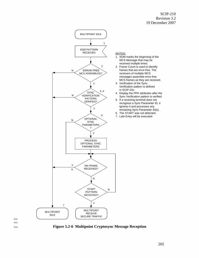
SCIP-210 Revision 3.2
19 December 2007
205
NOTES:1. SOM marks the beginning of the MCS Message that may be received multiple times.2. Frame Count is used to identify
frames that are error-free. The receivers of multiple MCS messages assemble error-free MCS frames as they are received.3. Verification of the Sync Verification pattern is defined in SCIP-23x.4. Display the PPK attributes after the Sync Verification pattern is verified.5. If a receiving terminal does not recognize a Sync Parameter ID, it ignores it and processes any remaining Sync Parameter ID(s).6. The START was not detected.7. Late Entry will be executed.
MULTIPOINT IDLE
1
SOM PATTERNRECEIVED
ERROR-FREEMCS ASSEMBLED?
Y
N
2
3, 4SYNCVERIFICATION
PATTERNVERIFIES?
Y
N
Y
N OPTIONALSYNC
PARAMETERS?
5
PROCESSOPTIONAL SYNC
PARAMETERS
MULTIPOINTRECEIVE
SECURE TRAFFIC
Y
NSTARTPATTERN
RECEIVED?
6
N
Y SM FRAMERECEIVED?
MULTIPOINTIDLE
7
5032
5033
Figure 5.2-6 Multipoint Cryptosync Message Reception 5034
SCIP-210 Revision 3.2 19 December 2007
206
5035
5.2.2.2 Multipoint Secure Traffic Reception 5036
5037
Multipoint secure traffic reception processing shall begin after the terminal transitions to the 5038
Multipoint Receive Secure Traffic state (see Figure 5.2-1). The Application IV included in the 5039
MCS Message (see Section 5.2.2.1) or assembled from the components in the Sync Management 5040
frames (see Section 5.2.2.3) shall be used for decryption. The Secure MELP Voice application 5041
is specified in Section 5.2.2.2.1 for multipoint secure traffic reception. The Secure G.729D 5042
Voice (see Section 5.2.2.2.2) and Secure Data (see Section 5.2.2.2.3) applications are TBSL. 5043
5044
Multipoint secure voice traffic reception processing is shown in Figure 5.2-7. Receiving 5045
terminals shall process multipoint secure traffic frames when they are received. If a received 5046
frame is a Sync Management frame, the receiving terminals shall validate synchronization using 5047
the Partial Long and Short components contained within the Sync Management frame, as 5048
specified in SCIP-23x for each application. This process is used to maintain cryptographic 5049
synchronization. 5050
5051
5052
MULTIPOINTRECEIVE
SECURE TRAFFIC
VALIDATESYNCHRONIZATION
WITH SM FRAMECOMPONENTS
MULTIPOINTRECEIVE
SECURE TRAFFIC
SM FRAMERECEIVED
2
NOTES:1. SM frames are inserted in the multipoint secure voice traffic.2. Synchronization validation with
the components contained within the SM frames is defined in SCIP-23x.
1
5053
5054
Figure 5.2-7 Multipoint Secure Voice Traffic Reception 5055
5056
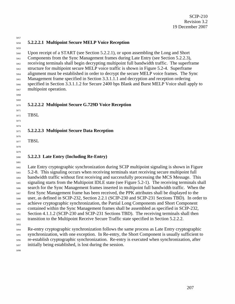
SCIP-210 Revision 3.2
19 December 2007
207
5057
5.2.2.2.1 Multipoint Secure MELP Voice Reception 5058
5059
Upon receipt of a START (see Section 5.2.2.1), or upon assembling the Long and Short 5060
Components from the Sync Management frames during Late Entry (see Section 5.2.2.3), 5061
receiving terminals shall begin decrypting multipoint full bandwidth traffic. The superframe 5062
structure for multipoint secure MELP voice traffic is shown in Figure 5.2-4. Superframe 5063
alignment must be established in order to decrypt the secure MELP voice frames. The Sync 5064
Management frame specified in Section 3.3.1.1.1 and decryption and reception ordering 5065
specified in Section 3.3.1.1.2 for Secure 2400 bps Blank and Burst MELP Voice shall apply to 5066
multipoint operation. 5067
5068
5069
5.2.2.2.2 Multipoint Secure G.729D Voice Reception 5070
5071
TBSL 5072
5073
5074
5.2.2.2.3 Multipoint Secure Data Reception 5075
5076
TBSL 5077
5078
5079
5.2.2.3 Late Entry (Including Re-Entry) 5080
5081
Late Entry cryptographic synchronization during SCIP multipoint signaling is shown in Figure 5082
5.2-8. This signaling occurs when receiving terminals start receiving secure multipoint full 5083
bandwidth traffic without first receiving and successfully processing the MCS Message. This 5084
signaling starts from the Multipoint IDLE state (see Figure 5.2-1). The receiving terminals shall 5085
search for the Sync Management frames inserted in multipoint full bandwidth traffic. When the 5086
first Sync Management frame has been received, the PPK attributes shall be displayed to the 5087
user, as defined in SCIP-232, Section 2.2.1 (SCIP-230 and SCIP-231 Sections TBD). In order to 5088
achieve cryptographic synchronization, the Partial Long Components and Short Component 5089
contained within the Sync Management frames shall be assembled as specified in SCIP-232, 5090
Section 4.1.1.2 (SCIP-230 and SCIP-231 Sections TBD). The receiving terminals shall then 5091
transition to the Multipoint Receive Secure Traffic state specified in Section 5.2.2.2. 5092
5093
Re-entry cryptographic synchronization follows the same process as Late Entry cryptographic 5094
synchronization, with one exception. In Re-entry, the Short Component is usually sufficient to 5095
re-establish cryptographic synchronization. Re-entry is executed when synchronization, after 5096
initially being established, is lost during the session. 5097
5098
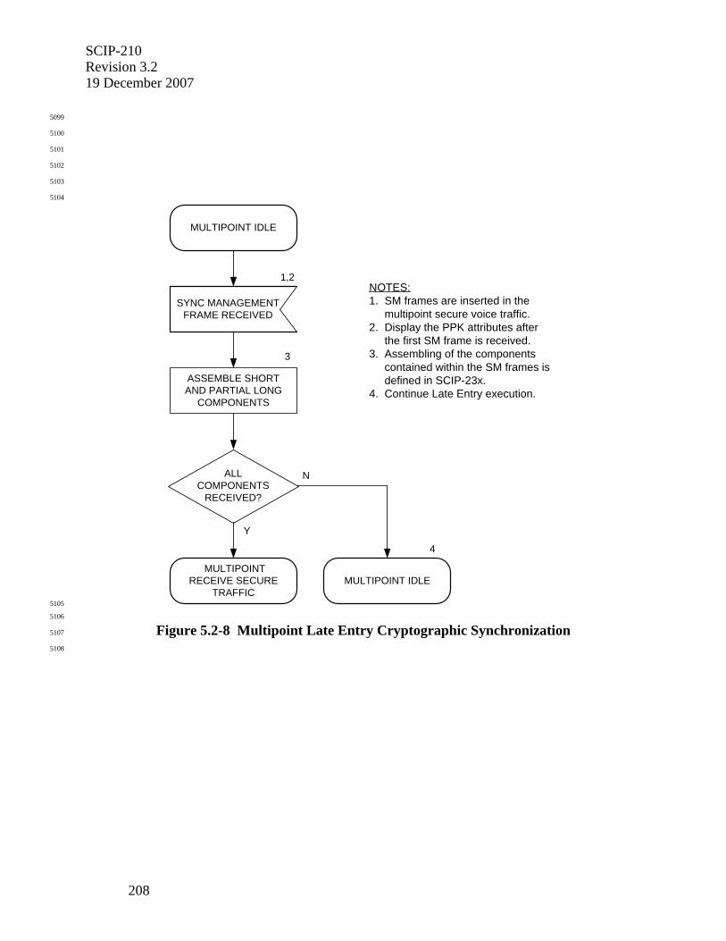
SCIP-210 Revision 3.2 19 December 2007
208
5099
5100
5101
5102
5103
5104
NOTES:1. SM frames are inserted in the multipoint secure voice traffic.2. Display the PPK attributes after
the first SM frame is received.3. Assembling of the components contained within the SM frames is
defined in SCIP-23x.4. Continue Late Entry execution.
1,2
SYNC MANAGEMENTFRAME RECEIVED
MULTIPOINT IDLE
ALLCOMPONENTS
RECEIVED?
Y
N
MULTIPOINTRECEIVE SECURE
TRAFFICMULTIPOINT IDLE
ASSEMBLE SHORTAND PARTIAL LONG
COMPONENTS
3
4
5105
5106
Figure 5.2-8 Multipoint Late Entry Cryptographic Synchronization 5107
5108
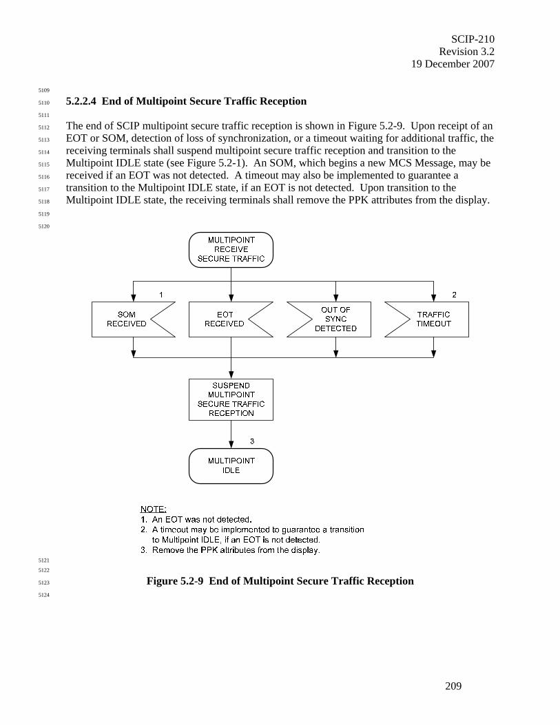
SCIP-210 Revision 3.2
19 December 2007
209
5109
5.2.2.4 End of Multipoint Secure Traffic Reception 5110
5111
The end of SCIP multipoint secure traffic reception is shown in Figure 5.2-9. Upon receipt of an 5112
EOT or SOM, detection of loss of synchronization, or a timeout waiting for additional traffic, the 5113
receiving terminals shall suspend multipoint secure traffic reception and transition to the 5114
Multipoint IDLE state (see Figure 5.2-1). An SOM, which begins a new MCS Message, may be 5115
received if an EOT was not detected. A timeout may also be implemented to guarantee a 5116
transition to the Multipoint IDLE state, if an EOT is not detected. Upon transition to the 5117
Multipoint IDLE state, the receiving terminals shall remove the PPK attributes from the display. 5118
5119
5120
5121
5122
Figure 5.2-9 End of Multipoint Secure Traffic Reception 5123
5124

SCIP-210 Revision 3.2 19 December 2007
210
5125
5126
5127
5128
5129
5130
5131
5132
5133
5134
5135
5136
5137
5138
5139
5140
5141
5142
5143
5144
5145
THIS PAGE INTENTIONALLY LEFT BLANK. 5146
5147
5148
5149
5150
SCIP-210 Revision 3.2
19 December 2007
A-1
5151
APPENDICES 5152
5153
A.0 SCIP MESSAGE TRANSPORT PROTOCOL EXAMPLES 5154
5155
This appendix provides several examples of the operation of the SCIP message transport control 5156
protocol. It contains no requirements. These examples are used to show messages from the 5157
Message Layer of Terminal A being sent to the Message Layer of Terminal B. Messages may be 5158
transferred in the opposite direction simultaneously; however, for clarity this is not shown. The 5159
transmit directions operate independently. 5160
5161
The following notation is used in the examples shown in this appendix. 5162
5163
5164
3 Frame #3 5165
5 Frame #5 received with uncorrectable errors 5166
Lost information 5167
Application Timer running 5168
RPT(4/5,30) REPORT message acknowledging Block #4 and requesting resend of Block #5 & Block #30
5169
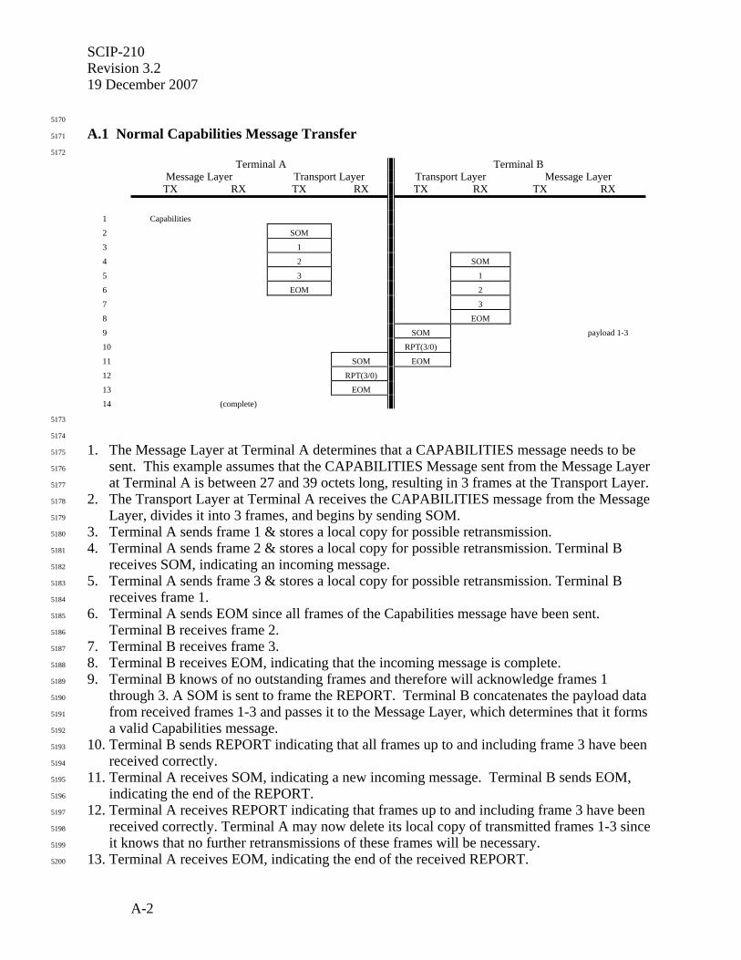
SCIP-210 Revision 3.2 19 December 2007
A-2
5170
A.1 Normal Capabilities Message Transfer 5171
5172
Terminal A Terminal B Message Layer Transport Layer Transport Layer Message Layer TX RX TX RX TX RX TX RX
1 Capabilities
2 SOM
3 1
4 2 SOM
5 3 1
6 EOM 2
7 3
8 EOM
9 SOM payload 1-3
10 RPT(3/0)
11 SOM EOM
12 RPT(3/0)
13 EOM
14 (complete)
5173
5174
1. The Message Layer at Terminal A determines that a CAPABILITIES message needs to be 5175
sent. This example assumes that the CAPABILITIES Message sent from the Message Layer 5176
at Terminal A is between 27 and 39 octets long, resulting in 3 frames at the Transport Layer. 5177
2. The Transport Layer at Terminal A receives the CAPABILITIES message from the Message 5178
Layer, divides it into 3 frames, and begins by sending SOM. 5179
3. Terminal A sends frame 1 & stores a local copy for possible retransmission. 5180
4. Terminal A sends frame 2 & stores a local copy for possible retransmission. Terminal B 5181
receives SOM, indicating an incoming message. 5182
5. Terminal A sends frame 3 & stores a local copy for possible retransmission. Terminal B 5183
receives frame 1. 5184
6. Terminal A sends EOM since all frames of the Capabilities message have been sent. 5185
Terminal B receives frame 2. 5186
7. Terminal B receives frame 3. 5187
8. Terminal B receives EOM, indicating that the incoming message is complete. 5188
9. Terminal B knows of no outstanding frames and therefore will acknowledge frames 1 5189
through 3. A SOM is sent to frame the REPORT. Terminal B concatenates the payload data 5190
from received frames 1-3 and passes it to the Message Layer, which determines that it forms 5191
a valid Capabilities message. 5192
10. Terminal B sends REPORT indicating that all frames up to and including frame 3 have been 5193
received correctly. 5194
11. Terminal A receives SOM, indicating a new incoming message. Terminal B sends EOM, 5195
indicating the end of the REPORT. 5196
12. Terminal A receives REPORT indicating that frames up to and including frame 3 have been 5197
received correctly. Terminal A may now delete its local copy of transmitted frames 1-3 since 5198
it knows that no further retransmissions of these frames will be necessary. 5199
13. Terminal A receives EOM, indicating the end of the received REPORT. 5200

SCIP-210 Revision 3.2
19 December 2007
A-3
14. If necessary, the Transport Layer at Terminal A may inform the Message Layer that the 5201
CAPABILITIES message has been successfully transported. 5202
5203
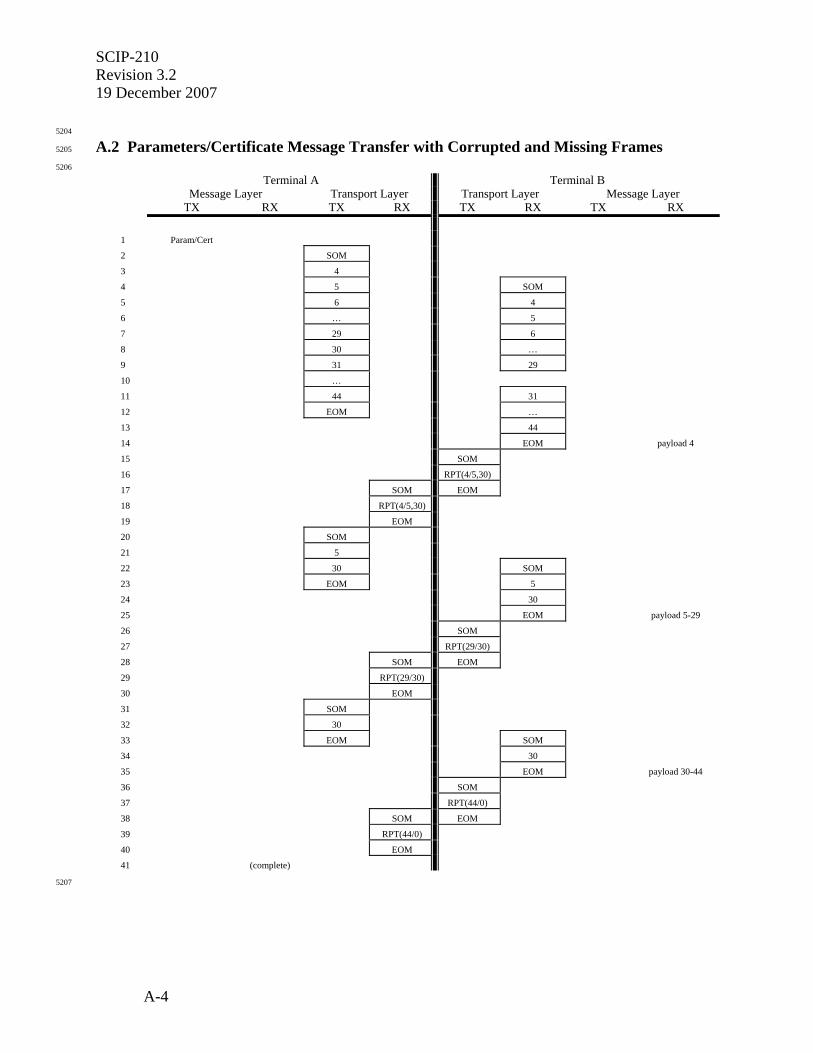
SCIP-210 Revision 3.2 19 December 2007
A-4
5204
A.2 Parameters/Certificate Message Transfer with Corrupted and Missing Frames 5205
5206
Terminal A Terminal B Message Layer Transport Layer Transport Layer Message Layer TX RX TX RX TX RX TX RX
1 Param/Cert
2 SOM
3 4
4 5 SOM
5 6 4
6 … 5
7 29 6
8 30 …
9 31 29
10 …
11 44 31
12 EOM …
13 44
14 EOM payload 4
15 SOM
16 RPT(4/5,30)
17 SOM EOM
18 RPT(4/5,30)
19 EOM
20 SOM
21 5
22 30 SOM
23 EOM 5
24 30
25 EOM payload 5-29
26 SOM
27 RPT(29/30)
28 SOM EOM
29 RPT(29/30)
30 EOM
31 SOM
32 30
33 EOM SOM
34 30
35 EOM payload 30-44
36 SOM
37 RPT(44/0)
38 SOM EOM
39 RPT(44/0)
40 EOM
41 (complete)
5207

SCIP-210 Revision 3.2
19 December 2007
A-5
5208
1. The Message Layer at Terminal A determines that a PARAMETERS/CERTIFICATE 5209
message needs to be sent. This example assumes that the PARAMETERS/CERTIFICATE 5210
Message sent from the Message Layer at Terminal A is between 521 and 533 octets long, 5211
resulting in 41 frames at the Transport Layer. 5212
2. The Transport Layer at Terminal A receives the PARAMETERS/CERTIFICATE message 5213
from the Message Layer, divides it into 41 frames, and begins by sending SOM. This 5214
example assumes that the most recent transmitted frame was frame 3, so the first frame is 5215
assigned frame number 4. 5216
3. Terminal A sends frame 4 & stores a local copy for possible retransmission. 5217
4. Terminal A sends frame 5 & stores a local copy for possible retransmission. Terminal B 5218
receives SOM, indicating an incoming message. 5219
5. Terminal A sends frame 6 & stores a local copy for possible retransmission. Terminal B 5220
receives frame 4. 5221
6. Terminal A sends frames 7 through 28 & stores local copies for possible retransmission. 5222
Terminal B receives frame 5 which is corrupted (i.e. CRC failure). Terminal B may 5223
immediately send a REPORT message indicating that frame 5 needs to be retransmitted or, 5224
as is shown in this example, store up all retransmission requests until the end of the incoming 5225
message. 5226
7. Terminal A sends frame 29 & stores a local copy for possible retransmission. Terminal B 5227
receives frame 6. 5228
8. Terminal A sends frame 30 & stores a local copy for possible retransmission. Terminal B 5229
receives frames 7 through 28. 5230
9. Terminal A sends frame 31 & stores a local copy for possible retransmission. Terminal B 5231
receives frame 29. 5232
10. Terminal A sends frames 32 through 43 & stores local copies for possible retransmission. 5233
Note that in this example frame 30 is lost in transmission and does not arrive at Terminal B. 5234
11. Terminal A sends frame 44 & stores a local copy for possible retransmission. Terminal B 5235
receives frame 31. Terminal B was expecting frame 30 and therefore adds frame 30 to the 5236
list of frames to be included on the NAK list in the REPORT message. 5237
12. Terminal A sends EOM since all frames of the PARAMETERS/CERTIFICATE message 5238
have been sent. Terminal B receives frames 32 through 43. 5239
13. Terminal B receives frame 44. 5240
14. Terminal B receives EOM indicating that the incoming message is complete. Terminal B 5241
passes data from all correctly received contiguous frames to the Message Layer, in this 5242
example from frame 4 only. The Message Layer is responsible for checking length fields 5243
and realizing that this is only a partial PARAMETERS/CERTIFICATE message. 5244
15. Terminal B sends SOM to frame the REPORT. 5245
16. Terminal B sends REPORT indicating that up through frame 4 has been received correctly 5246
while frames 5 and 30 need to be retransmitted. 5247
17. Terminal A receives SOM indicating the beginning of an incoming message. Terminal B 5248
sends EOM to frame the REPORT. 5249
18. Terminal A receives REPORT indicating that up through frame 4 has been received correctly 5250
and requesting that frames 5 and 30 be retransmitted. Terminal A may now delete its local 5251
copy of transmitted frame 4 since it knows that no further retransmissions of this frame will 5252
be necessary. 5253
SCIP-210 Revision 3.2 19 December 2007
A-6
19. Terminal A receives EOM indicating that the incoming REPORT is complete. 5254
20. Terminal A sends SOM to frame the retransmitted frames. 5255
21. Terminal A retransmits frame 5. 5256
22. Terminal A retransmits frame 30. Terminal B receives SOM indicating the beginning of an 5257
incoming message. 5258
23. Terminal A sends EOM to frame the retransmitted frames. Terminal B receives frame 5. 5259
24. Terminal B receives frame 30, which in this example is corrupted (CRC failure). 5260
25. Terminal B receives EOM indicating that the incoming message is complete. Terminal B 5261
passes data from all correctly received contiguous frames to the Message Layer, in this 5262
example from frames 5 through 29. The Message Layer is responsible for checking length 5263
fields and realizing that this is still only a partial PARAMETERS/CERTIFICATE message. 5264
26. Terminal B sends SOM to frame the REPORT. 5265
27. Terminal B sends REPORT indicating that up through frame 29 has been received correctly 5266
while frame 30 needs to be retransmitted 5267
28. Terminal A receives SOM indicating the beginning of an incoming message. Terminal B 5268
sends EOM to frame the REPORT. 5269
29. Terminal A receives REPORT indicating that up through frame 29 has been received 5270
correctly and requesting that frame 30 be retransmitted. Terminal A may now delete its local 5271
copy of transmitted frames 5-29 since it knows that no further retransmissions of these 5272
frames will be necessary. 5273
30. Terminal A receives EOM indicating that the incoming REPORT is complete. 5274
31. Terminal A sends SOM to frame the retransmitted frames. 5275
32. Terminal A retransmits frame 30. 5276
33. Terminal A sends EOM to frame the retransmitted frame. Terminal B receives SOM 5277
indicating the beginning of an incoming message. 5278
34. Terminal B receives frame 30. 5279
35. Terminal B receives EOM indicating that the incoming message is complete. Terminal B 5280
passes data from all correctly received contiguous frames to the Message Layer, in this 5281
example from frames 30 through 44. The Message Layer is responsible for checking length 5282
fields and realizing that the PARAMETERS/CERTIFICATE message is now complete. 5283
36. Terminal B knows of no more outstanding frames and will therefore respond to the received 5284
EOM by sending a REPORT message containing only an acknowledge frame value. 5285
Terminal B sends SOM to frame the REPORT. 5286
37. Terminal B sends REPORT indicating that all frames up to and including frame 44 have been 5287
received correctly. 5288
38. Terminal A receives SOM, indicating a new incoming message. Terminal B sends EOM 5289
which frames the REPORT. Terminal A receives SOM indicating an incoming message. 5290
39. Terminal A receives REPORT indicating that frames up to and including frame 44 have been 5291
received correctly. Terminal A may now delete its local copy of transmitted frames 30-44 5292
since it knows that no further retransmissions of these frames will be necessary. 5293
40. Terminal A receives EOM, indicating the end of the received REPORT. 5294
41. If necessary, the Transport Layer may inform the Message Layer that the 5295
PARAMETERS/CERTIFICATE message has been successfully transported. 5296
5297
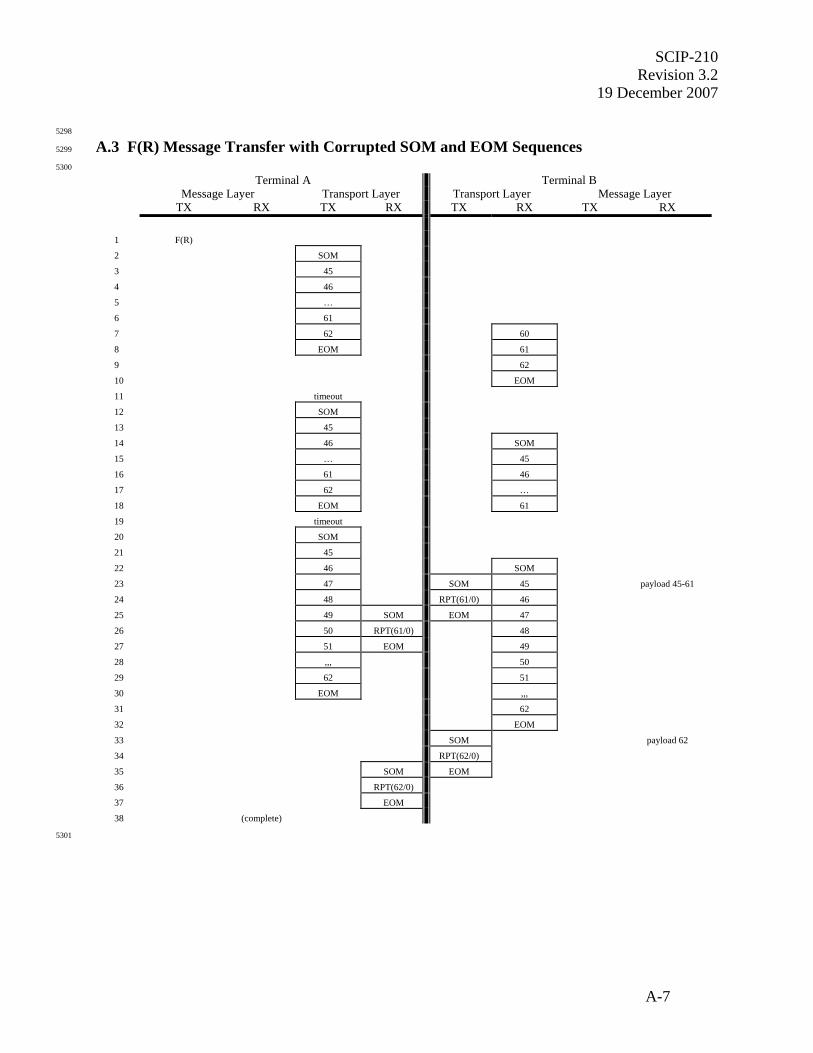
SCIP-210 Revision 3.2
19 December 2007
A-7
5298
A.3 F(R) Message Transfer with Corrupted SOM and EOM Sequences 5299
5300
Terminal A Terminal B Message Layer Transport Layer Transport Layer Message Layer TX RX TX RX TX RX TX RX
1 F(R)
2 SOM
3 45
4 46
5 …
6 61
7 62 60
8 EOM 61
9 62
10 EOM
11 timeout
12 SOM
13 45
14 46 SOM
15 … 45
16 61 46
17 62 …
18 EOM 61
19 timeout
20 SOM
21 45
22 46 SOM
23 47 SOM 45 payload 45-61
24 48 RPT(61/0) 46
25 49 SOM EOM 47
26 50 RPT(61/0) 48
27 51 EOM 49
28 ,,, 50
29 62 51
30 EOM ,,,
31 62
32 EOM
33 SOM payload 62
34 RPT(62/0)
35 SOM EOM
36 RPT(62/0)
37 EOM
38 (complete)
5301

SCIP-210 Revision 3.2 19 December 2007
A-8
5302
1. The Message Layer at Terminal A determines that a F(R) message needs to be sent. This 5303
example assumes that the F(R) Message sent from the Message Layer at Terminal A is 5304
between 222 and 223 octets long, resulting in 18 frames at the Transport Layer. 5305
2. The Transport Layer at Terminal A receives the F(R) message from the Message Layer, 5306
divides it into 18 frames, and begins by sending SOM. This example assumes that the most 5307
recent transmitted frame was frame 44, so the first frame is assigned frame number 45. 5308
3. Terminal A sends frame 45 & stores a local copy for possible retransmission. 5309
4. Terminal A sends frame 46 & stores a local copy for possible retransmission. Terminal B 5310
should have received SOM at this time, but this example assumes that the SOM and first 5311
frames are not received. 5312
5. Terminal A sends frames 47 through 60 & stores a local copy for possible retransmission 5313
6. Terminal A sends frame 61 and stores a local copy for possible retransmission. 5314
7. Terminal A sends frame 62 and stores a local copy for possible retransmission. Terminal B 5315
receives frame 60, although it isn’t recognized because it was not preceded by SOM 5316
8. Terminal A sends EOM since all frames of the F(R) message have been sent. Terminal B 5317
receives frame 61, although it isn’t recognized because it was not preceded by SOM. 5318
9. Terminal B receives frame 62, although it isn’t recognized because it was not preceded by 5319
SOM. 5320
10. Terminal B receives EOM without having seen SOM. As a local implementation option, 5321
Terminal B can work backwards from the EOM to identify missing frames based on which 5322
frames were expected (in this example frames 45 through 59 were missing) and then send 5323
REPORT with the NAK list indicating the missing frames. Another valid approach is for 5324
Terminal B to ignore the entire received message since it was not preceded by SOM. This 5325
more simplistic approach is shown in this example. 5326
11. The retransmission timeout at Terminal A expires because Terminal A has not received 5327
REPORT in response to the frames it transmitted. Terminal A will retransmit frames 45 5328
through 62. 5329
12. Terminal A begins the retransmission with SOM. 5330
13. Terminal A retransmits frame 45. 5331
14. Terminal A retransmits frame 46. Terminal B receives SOM, indicating an incoming 5332
message. 5333
15. Terminal A retransmits frames 47 through 60. Terminal B receives frame 45. 5334
16. Terminal A retransmits frame 61. Terminal B receives frame 46. 5335
17. Terminal A retransmits frame 62. Terminal B receives frames 47 through 60. 5336
18. Terminal A sends EOM since all frames have been retransmitted. Terminal B receives frame 5337
61. 5338
19. Terminal B stops receiving frames without having seen an EOM. As a local implementation 5339
option, Terminal B may timeout and send REPORT indicating all contiguously received 5340
frames (through frame 61 in this example). An alternative valid approach is for Terminal B 5341
to not send REPORT since EOM was not seen. This more simplistic approach is shown in 5342
this example. The retransmission timeout at Terminal A expires because Terminal A has not 5343
received REPORT in response to the frames it transmitted. Terminal A will retransmit 5344
frames 45 through 62. 5345
20. Terminal A begins the retransmission with SOM. 5346
21. Terminal A retransmits frame 45. 5347
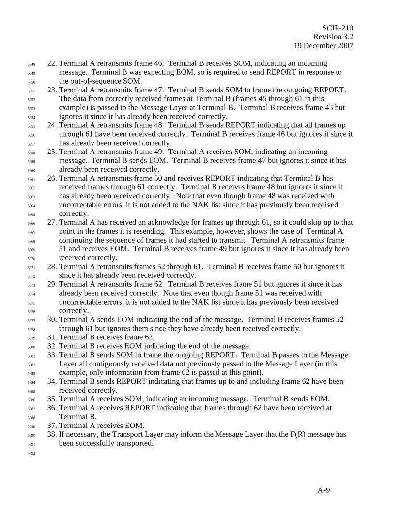
SCIP-210 Revision 3.2
19 December 2007
A-9
22. Terminal A retransmits frame 46. Terminal B receives SOM, indicating an incoming 5348
message. Terminal B was expecting EOM, so is required to send REPORT in response to 5349
the out-of-sequence SOM. 5350
23. Terminal A retransmits frame 47. Terminal B sends SOM to frame the outgoing REPORT. 5351
The data from correctly received frames at Terminal B (frames 45 through 61 in this 5352
example) is passed to the Message Layer at Terminal B. Terminal B receives frame 45 but 5353
ignores it since it has already been received correctly. 5354
24. Terminal A retransmits frame 48. Terminal B sends REPORT indicating that all frames up 5355
through 61 have been received correctly. Terminal B receives frame 46 but ignores it since it 5356
has already been received correctly. 5357
25. Terminal A retransmits frame 49. Terminal A receives SOM, indicating an incoming 5358
message. Terminal B sends EOM. Terminal B receives frame 47 but ignores it since it has 5359
already been received correctly. 5360
26. Terminal A retransmits frame 50 and receives REPORT indicating that Terminal B has 5361
received frames through 61 correctly. Terminal B receives frame 48 but ignores it since it 5362
has already been received correctly. Note that even though frame 48 was received with 5363
uncorrectable errors, it is not added to the NAK list since it has previously been received 5364
correctly. 5365
27. Terminal A has received an acknowledge for frames up through 61, so it could skip up to that 5366
point in the frames it is resending. This example, however, shows the case of Terminal A 5367
continuing the sequence of frames it had started to transmit. Terminal A retransmits frame 5368
51 and receives EOM. Terminal B receives frame 49 but ignores it since it has already been 5369
received correctly. 5370
28. Terminal A retransmits frames 52 through 61. Terminal B receives frame 50 but ignores it 5371
since it has already been received correctly. 5372
29. Terminal A retransmits frame 62. Terminal B receives frame 51 but ignores it since it has 5373
already been received correctly. Note that even though frame 51 was received with 5374
uncorrectable errors, it is not added to the NAK list since it has previously been received 5375
correctly. 5376
30. Terminal A sends EOM indicating the end of the message. Terminal B receives frames 52 5377
through 61 but ignores them since they have already been received correctly. 5378
31. Terminal B receives frame 62. 5379
32. Terminal B receives EOM indicating the end of the message. 5380
33. Terminal B sends SOM to frame the outgoing REPORT. Terminal B passes to the Message 5381
Layer all contiguously received data not previously passed to the Message Layer (in this 5382
example, only information from frame 62 is passed at this point). 5383
34. Terminal B sends REPORT indicating that frames up to and including frame 62 have been 5384
received correctly. 5385
35. Terminal A receives SOM, indicating an incoming message. Terminal B sends EOM. 5386
36. Terminal A receives REPORT indicating that frames through 62 have been received at 5387
Terminal B. 5388
37. Terminal A receives EOM. 5389
38. If necessary, the Transport Layer may inform the Message Layer that the F(R) message has 5390
been successfully transported. 5391
5392
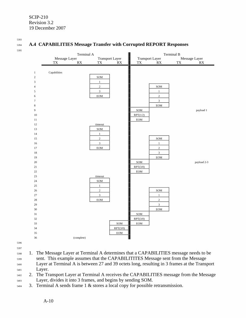
SCIP-210 Revision 3.2 19 December 2007
A-10
5393
A.4 CAPABILITIES Message Transfer with Corrupted REPORT Responses 5394
5395
Terminal A Terminal B Message Layer Transport Layer Transport Layer Message Layer TX RX TX RX TX RX TX RX
1 Capabilities
2 SOM
3 1
4 2 SOM
5 3 1
6 EOM 2
7 3
8 EOM
9 SOM payload 1
10 RPT(1/2)
11 EOM
12 timeout
13 SOM
14 1
15 2 SOM
16 3 1
17 EOM 2
18 3
19 EOM
20 SOM payload 2-3
21 RPT(3/0)
22 EOM
23 timeout
24 SOM
25 1
26 2 SOM
27 3 1
28 EOM 2
29 3
30 EOM
31 SOM
32 RPT(3/0)
33 SOM EOM
34 RPT(3/0)
35 EOM
36 (complete)
5396
5397
1. The Message Layer at Terminal A determines that a CAPABILITIES message needs to be 5398
sent. This example assumes that the CAPABILITITES Message sent from the Message 5399
Layer at Terminal A is between 27 and 39 octets long, resulting in 3 frames at the Transport 5400
Layer. 5401
2. The Transport Layer at Terminal A receives the CAPABILITIES message from the Message 5402
Layer, divides it into 3 frames, and begins by sending SOM. 5403
3. Terminal A sends frame 1 & stores a local copy for possible retransmission. 5404

SCIP-210 Revision 3.2
19 December 2007
A-11
4. Terminal A sends frame 2 & stores a local copy for possible retransmission. Terminal B 5405
receives SOM indicating the beginning of an incoming message. 5406
5. Terminal A sends frame 3 & stores a local copy for possible retransmission. Terminal B 5407
receives frame 1. 5408
6. The Transport Layer at Terminal A has sent the entire message it received from the Message 5409
Layer so it sends EOM. Terminal B receives frame 2, which is corrupt (CRC failure). 5410
7. Terminal B receives frame 3. 5411
8. Terminal B receives EOM. Terminal B knows that there is a missing frame in the received 5412
sequence so it will add the missing frame number to the NAK list in the REPORT message. 5413
9. Terminal B sends SOM in preparation for sending REPORT. Terminal B also passes along 5414
to the Message Layer the data from all contiguously received frames (only frame 1 in this 5415
example). 5416
10. Terminal B sends REPORT indicating that up through frame 1 has been received correctly 5417
and requesting that that frame 2 be retransmitted. 5418
11. Terminal B sends EOM. Terminal A should begin receiving the SOM at this point, but this 5419
example assumes that the entire REPORT message, including the SOM and EOM framing, is 5420
lost. 5421
12. The retransmission timeout at Terminal A expires, indicating that Terminal A has not 5422
received REPORT. Terminal A must retransmit the entire message. 5423
13. Terminal A sends SOM in preparation for retransmitting the entire message. 5424
14. Terminal A retransmits frame 1. 5425
15. Terminal A retransmits frame 2. Terminal B receives SOM indicating an incoming message. 5426
16. Terminal A retransmits frame 3. Terminal B receives frame 1, recognizes that frame 1 has 5427
already been received error-free, and discards the newly received copy. Note that even 5428
though frame 1 is received with uncorrectable errors it is not added to the NAK list since it 5429
has previously been received error-free. 5430
17. Terminal A sends EOM. Terminal B receives frame 2. 5431
18. Terminal B receives frame 3, recognizes that frame 3 has already been received error-free, 5432
and discards the newly received copy. 5433
19. Terminal B receives EOM. All frames received by Terminal B at this point are contiguous, 5434
so Terminal B will respond with REPORT containing a null NAK list. 5435
20. Terminal B sends SOM to frame the REPORT. Terminal B also passes the information 5436
contained in all contiguously received frames (frames 2 and 3 in this example) to the 5437
Message Layer. 5438
21. Terminal B sends REPORT, indicating that frames up to and including frame 3 have been 5439
received correctly. 5440
22. Terminal B sends EOM. Terminal A should begin receiving the SOM at this point, but this 5441
example assumes that the entire REPORT message, including the SOM and EOM framing, is 5442
lost. 5443
23. The retransmission timeout at Terminal A expires, indicating that Terminal A has not 5444
received REPORT. Terminal A must retransmit the entire message. 5445
24. Terminal A sends SOM in preparation for retransmitting the entire message. 5446
25. Terminal A retransmits frame 1. 5447
26. Terminal A retransmits frame 2. Terminal B receives SOM indicating an incoming message. 5448
SCIP-210 Revision 3.2 19 December 2007
A-12
27. Terminal A retransmits frame 3. Terminal B receives frame 1, recognizes that frame 1 has 5449
already been received error-free, and discards the newly received copy. Note that even 5450
though frame 1 is received with uncorrectable errors it is not added to the NAK list since it 5451
has previously been received error-free. 5452
28. Terminal A sends EOM. Terminal B receives frame 2, recognizes that frame 2 has already 5453
been received error-free, and discards the newly received copy. Note that even though frame 5454
2 is received with uncorrectable errors it is not added to the NAK list since it has previously 5455
been received error-free. 5456
29. Terminal B receives frame 3, recognizes that frame 3 has already been received error-free, 5457
and discards the newly received copy. Note that even though frame 3 is received with 5458
uncorrectable errors it is not added to the NAK list since it has previously been received 5459
error-free. 5460
30. Terminal B receives EOM. All frames received by Terminal B at this point are contiguous, 5461
so Terminal B will respond with REPORT containing a null NAK list. Even though 5462
Terminal B has already sent a REPORT message acknowledging through block 3, it must 5463
send it again to prevent Terminal A from retransmitting again. 5464
31. Terminal B sends SOM to frame the REPORT. 5465
32. Terminal B sends REPORT, indicating that frames up to and including frame 3 have been 5466
received correctly. 5467
33. Terminal B sends EOM. Terminal A receives SOM, indicating an incoming message. 5468
34. Terminal A receives REPORT indicating that all frames through frame 3 have been received 5469
correctly. Terminal A may now discard the locally stored copies of frames 1, 2, and 3. 5470
35. Terminal A receives EOM. 5471
36. If necessary, the Transport Layer may inform the Message Layer that the CAPABILITIES 5472
message has been successfully transported. 5473
5474
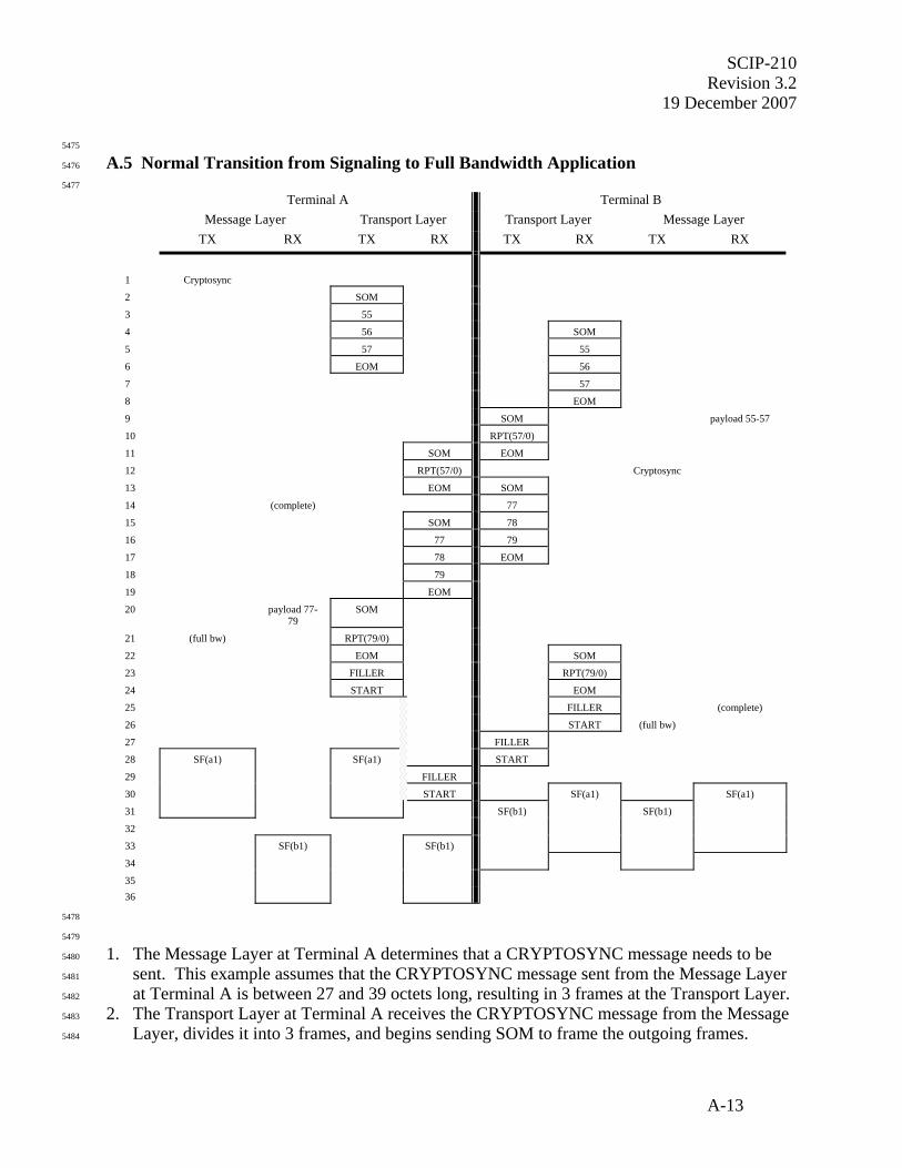
SCIP-210 Revision 3.2
19 December 2007
A-13
5475
A.5 Normal Transition from Signaling to Full Bandwidth Application 5476
5477
Terminal A Terminal B
Message Layer Transport Layer Transport Layer Message Layer
TX RX TX RX TX RX TX RX
1 Cryptosync
2 SOM
3 55
4 56 SOM
5 57 55
6 EOM 56
7 57
8 EOM
9 SOM payload 55-57
10 RPT(57/0)
11 SOM EOM
12 RPT(57/0) Cryptosync
13 EOM SOM
14 (complete) 77
15 SOM 78
16 77 79
17 78 EOM
18 79
19 EOM
20 payload 77-79
SOM
21 (full bw) RPT(79/0)
22 EOM SOM
23 FILLER RPT(79/0)
24 START EOM
25 FILLER (complete)
26 START (full bw)
27 FILLER
28 SF(a1) SF(a1) START
29 FILLER
30 START SF(a1) SF(a1)
31 SF(b1) SF(b1)
32
33 SF(b1) SF(b1)
34
35 36
5478
5479
1. The Message Layer at Terminal A determines that a CRYPTOSYNC message needs to be 5480
sent. This example assumes that the CRYPTOSYNC message sent from the Message Layer 5481
at Terminal A is between 27 and 39 octets long, resulting in 3 frames at the Transport Layer. 5482
2. The Transport Layer at Terminal A receives the CRYPTOSYNC message from the Message 5483
Layer, divides it into 3 frames, and begins sending SOM to frame the outgoing frames. 5484

SCIP-210 Revision 3.2 19 December 2007
A-14
3. This example assumes that the most recent transmitted frame from Terminal A was number 5485
54. Terminal A sends frame 55 & stores a local copy for possible retransmission. 5486
4. Terminal A sends frame 56 & stores a local copy for possible retransmission. Terminal B 5487
receives SOM, indicating an incoming message. 5488
5. Terminal A sends frame 57 & stores a local copy for possible retransmission. Terminal B 5489
receives frame 55. 5490
6. Terminal A sends EOM since all frames of the CRYPTOSYNC message have been sent. 5491
Terminal B receives frame 56. 5492
7. Terminal B receives frame 57. 5493
8. Terminal B receives EOM, indicating that the incoming message is complete. 5494
9. Terminal B knows of no outstanding frames and will therefore send a REPORT message 5495
indicating that frames up through 57 have been received correctly. A SOM is sent to frame 5496
the REPORT message. Terminal B concatenates the payload data from received frames 55-5497
57 and passes it to the Message Layer, which determines that it forms a valid 5498
CRYPTOSYNC message. 5499
10. Terminal B sends REPORT indicating that all frames up to and including frame 57 have been 5500
received correctly. 5501
11. Terminal A receives SOM, indicating a new incoming message. Terminal B sends EOM, 5502
indicating the end of the REPORT. 5503
12. Terminal A receives REPORT indicating that frames up to and including frame 57 have been 5504
received correctly. Terminal A may now delete its local copy of transmitted frames 55-57 5505
since it knows that no further retransmissions of these frames will be necessary. This 5506
example assumes that at this time Terminal B determines that a CRYPTOSYNC message 5507
needs to be sent. The CRYPTOSYNC message is passed from the Message Layer to the 5508
Transport Layer at Terminal B. 5509
13. Terminal A receives EOM, indicating the end of the received REPORT. Terminal B sends 5510
SOM to frame the outgoing Transport Layer frames. 5511
14. The Transport Layer at Terminal A informs the Message Layer that the CRYPTOSYNC 5512
message has been successfully transported. Terminal B sends frame 77 and stores a local 5513
copy for possible retransmission. 5514
15. Terminal B sends frame 78 & stores a local copy for possible retransmission. Terminal A 5515
receives SOM, indicating the beginning of an incoming message. 5516
16. Terminal B sends frame 79 & stores a local copy for possible retransmission. Terminal A 5517
receives frame 77. 5518
17. Terminal A receives frame 78. Terminal B sends EOM since all frames of the 5519
CRYPTOSYNC message have been sent. 5520
18. Terminal A receives frame 79. 5521
19. Terminal A receives EOM, indicating that the incoming message is complete. 5522
20. Terminal A knows of no outstanding frames and will therefore send REPORT indicating that 5523
all frames up through 79 have been received correctly. A SOM is sent to frame the REPORT. 5524
Terminal A concatenates the payload data from received frames 77-79 and passes it to the 5525
Message Layer, which determines that it forms a valid CRYPTOSYNC message. 5526
21. Terminal A sends REPORT indicating that all frames up to and including frame 79 have 5527
been received correctly. Terminal A now knows that it is ready to transition to full bandwidth 5528
traffic. The Message Layer informs the Transport Layer that the change should occur as 5529
soon as any queued Transport Layer frames are sent. 5530
SCIP-210 Revision 3.2
19 December 2007
A-15
22. Terminal B receives SOM, indicating a new incoming message. Terminal A sends EOM, 5531
indicating the end of the REPORT. 5532
23. Terminal A sends FILLER in preparation for the transition from signaling to traffic. 5533
Terminal B receives REPORT indicating that all frames up through 79 have been received 5534
correctly. 5535
24. Terminal A sends START, indicating that subsequent transmissions will be full bandwidth 5536
traffic. Terminal A has not detected incoming START, so the Application Timer is started. 5537
Terminal B receives EOM, indicating the end of the received REPORT. 5538
25. Terminal B informs the Message Layer that the CRYPTOSYNC message has been 5539
successfully transported. Terminal B also receives FILLER. 5540
26. Terminal B now knows that it is ready to transition to full bandwidth traffic. The Message 5541
Layer informs the Transport Layer that the change should occur as soon as any queued 5542
Transport Layer frames are sent. Terminal B also receives START, indicating that 5543
subsequent incoming information will be full bandwidth. Terminal B begins searching for 5544
ESC and Sync Management patterns rather than SOM and START patterns 5545
27. Terminal B sends FILLER in preparation for the transition from signaling to traffic. 5546
28. This example assumes at this point that voice frames are available to be transmitted from 5547
Terminal A. The Message Layer at Terminal A begins transferring the first superframe (a1). 5548
Terminal B sends START, indicating that subsequent transmissions will be full bandwidth 5549
traffic. Terminal B does not start its Application Timer since incoming START has already 5550
been detected and Terminal B is no longer searching for incoming START. 5551
29. Terminal A continues sending superframe a1 and receives incoming FILLER. 5552
30. Terminal A continues sending superframe a1 and receives incoming START from Terminal 5553
B. Terminal A stops the Application Timer which has been running since START was 5554
transmitted. Terminal A begins searching for ESC and Sync Management patterns rather 5555
than SOM and START patterns. Terminal B begins receiving superframe a1 from Terminal 5556
A. 5557
31. Terminal A continues sending superframe a1. This example assumes at this point that voice 5558
frames are available to be transmitted from Terminal B. The Message Layer at Terminal B 5559
begins sending the first superframe (b1). 5560
32. Terminal B continues sending superframe b1 and receiving superframe a1. 5561
33. Terminal A begins receiving superframe b1. Terminal B continues sending superframe b1 5562
and receiving superframe a1. 5563
34. Terminal A continues receiving superframe b1. Terminal B continues sending superframe 5564
b1. 5565
35. Terminal A continues receiving superframe b1. 5566
36. Terminal A continues receiving superframe b1. 5567
5568
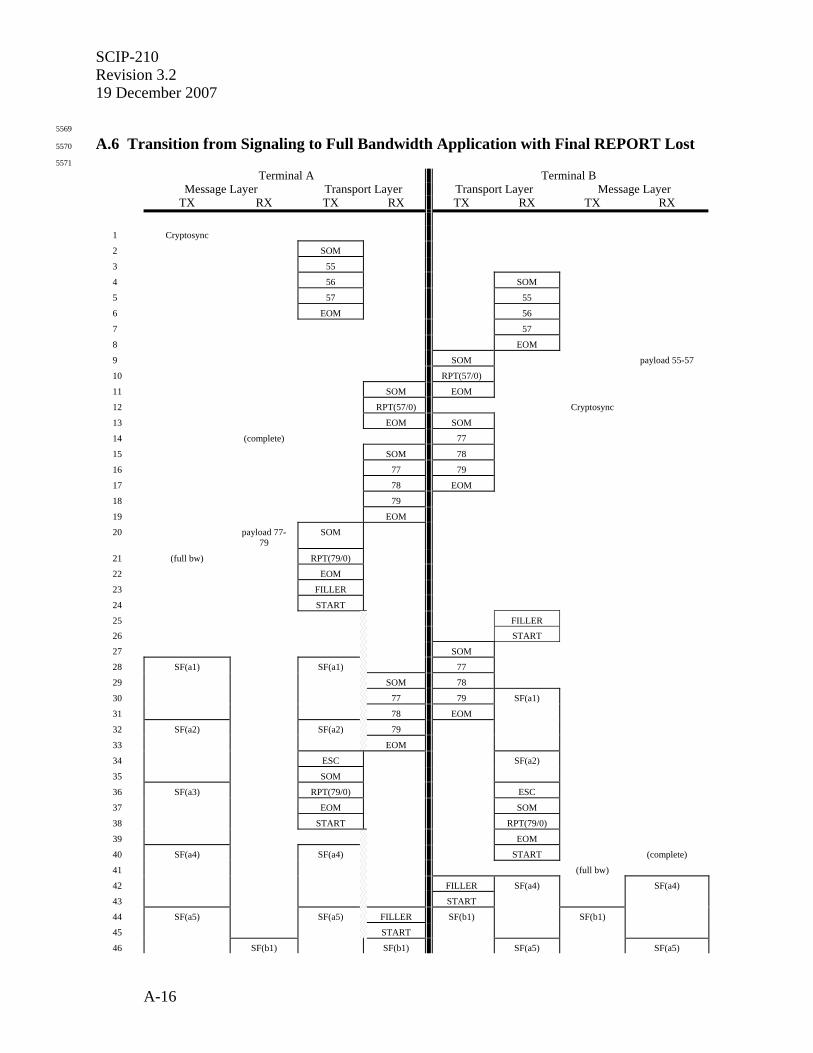
SCIP-210 Revision 3.2 19 December 2007
A-16
5569
A.6 Transition from Signaling to Full Bandwidth Application with Final REPORT Lost 5570
5571 Terminal A Terminal B Message Layer Transport Layer Transport Layer Message Layer TX RX TX RX TX RX TX RX
1 Cryptosync
2 SOM
3 55
4 56 SOM
5 57 55
6 EOM 56
7 57
8 EOM
9 SOM payload 55-57
10 RPT(57/0)
11 SOM EOM
12 RPT(57/0) Cryptosync
13 EOM SOM
14 (complete) 77
15 SOM 78
16 77 79
17 78 EOM
18 79
19 EOM
20 payload 77-79
SOM
21 (full bw) RPT(79/0)
22 EOM
23 FILLER
24 START
25 FILLER 26 START
27 SOM
28 SF(a1) SF(a1) 77
29 SOM 78
30 77 79 SF(a1)
31 78 EOM
32 SF(a2) SF(a2) 79
33 EOM
34 ESC SF(a2)
35 SOM
36 SF(a3) RPT(79/0) ESC
37 EOM SOM
38 START RPT(79/0)
39 EOM
40 SF(a4) SF(a4) START (complete)
41 (full bw)
42 FILLER SF(a4) SF(a4)
43 START
44 SF(a5) SF(a5) FILLER SF(b1) SF(b1)
45 START
46 SF(b1) SF(b1) SF(a5) SF(a5)

SCIP-210 Revision 3.2
19 December 2007
A-17
5572
5573
1. The Message Layer at Terminal A determines that a CRYPTOSYNC message needs to be 5574
sent. This example assumes that the CRYPTOSYNC message sent from the Message Layer 5575
at Terminal A is between 27 and 39 octets long, resulting in 3 frames at the Transport Layer. 5576
2. The Transport Layer at Terminal A receives the CRYPTOSYNC message from the Message 5577
Layer, divides it into 3 frames, and begins sending SOM to frame the outgoing frames. 5578
3. This example assumes that the most recent transmitted frame from Terminal A was number 5579
54. Terminal A sends frame 55 & stores a local copy for possible retransmission. 5580
4. Terminal A sends frame 56 & stores a local copy for possible retransmission. Terminal B 5581
receives SOM, indicating an incoming message. 5582
5. Terminal A sends frame 57 & stores a local copy for possible retransmission. Terminal B 5583
receives frame 55. 5584
6. Terminal A sends EOM since all frames of the CRYPTOSYNC message have been sent. 5585
Terminal B receives frame 56. 5586
7. Terminal B receives frame 57. 5587
8. Terminal B receives EOM, indicating that the incoming message is complete. 5588
9. Terminal B knows of no outstanding frames and will therefore send a REPORT message 5589
indicating that frames up through 57 have been received correctly. A SOM is sent to frame 5590
the REPORT message. Terminal B concatenates the payload data from received frames 55-5591
57 and passes it to the Message Layer, which determines that it forms a valid 5592
CRYPTOSYNC message. 5593
10. Terminal B sends REPORT indicating that all frames up to and including frame 57 have been 5594
received correctly. 5595
11. Terminal A receives SOM, indicating a new incoming message. Terminal B sends EOM, 5596
indicating the end of the REPORT. 5597
12. Terminal A receives REPORT indicating that frames up to and including frame 57 have been 5598
received correctly. Terminal A may now delete its local copy of transmitted frames 55-57 5599
since it knows that no further retransmissions of these frames will be necessary. This 5600
example assumes that at this time Terminal B determines that a CRYPTOSYNC message 5601
needs to be sent. The CRYPTOSYNC message is passed from the Message Layer to the 5602
Transport Layer at Terminal B. 5603
13. Terminal A receives EOM, indicating the end of the received REPORT. Terminal B sends 5604
SOM to frame the outgoing Transport Layer frames. 5605
14. The Transport Layer at Terminal A informs the Message Layer that the CRYPTOSYNC 5606
message has been successfully transported. Terminal B sends frame 77 and stores a local 5607
copy for possible retransmission. 5608
15. Terminal B sends frame 78 & stores a local copy for possible retransmission. Terminal A 5609
receives SOM, indicating the beginning of an incoming message. 5610
16. Terminal B sends frame 79 & stores a local copy for possible retransmission. Terminal A 5611
receives frame 77. 5612
17. Terminal A receives frame 78. Terminal B sends EOM since all frames of the 5613
CRYPTOSYNC message have been sent. 5614
18. Terminal A receives frame 79. 5615
19. Terminal A receives EOM, indicating that the incoming message is complete. 5616

SCIP-210 Revision 3.2 19 December 2007
A-18
20. Terminal A knows of no outstanding frames and will therefore send REPORT indicating that 5617
all frames up through 79 have been received correctly. A SOM is sent to frame the REPORT. 5618
Terminal A concatenates the payload data from received frames 77-79 and passes it to the 5619
Message Layer, which determines that it forms a valid CRYPTOSYNC message. 5620
21. Terminal A sends REPORT indicating that all frames up to and including frame 79 have 5621
been received correctly. Terminal A now knows that it is ready to transition to full bandwidth 5622
traffic. The Message Layer informs the Transport Layer that the change should occur as 5623
soon as any queued Transport Layer frames are sent. 5624
22. This example assumes that Terminal B does not receive SOM from Terminal A which should 5625
have arrived at this point. Terminal A sends EOM indicating the end of the REPORT. 5626
23. Terminal A sends FILLER in preparation for the transition from signaling to traffic. This 5627
example assumes that Terminal B does not receive REPORT(79/0) from Terminal A which 5628
should have arrived at this point. 5629
24. Terminal A sends START, indicating that subsequent transmissions will be full bandwidth 5630
traffic. Terminal A has not detected incoming START, so the Application Timer is started. 5631
This example assumes that Terminal B does not receive EOM from Terminal A which should 5632
have arrived at this point. 5633
25. Terminal B receives FILLER. 5634
26. Terminal B receives START, indicating that subsequent incoming information will be full 5635
bandwidth. Terminal B begins searching for ESC and Sync Management patterns rather than 5636
SOM and START patterns. 5637
27. Terminal B times out waiting for Terminal A to acknowledge outstanding Transport Layer 5638
frames. Terminal B must therefore resend the previous frames to trigger another REPORT 5639
message from Terminal A. Terminal B sends SOM to frame the outgoing frames. Note that 5640
these outgoing frames do not need to be preceded by ESC since Terminal B has not sent a 5641
START message. 5642
28. This example assumes at this point that voice frames are available to be transmitted from 5643
Terminal A. The Message layer at Terminal A begins sending superframe a1. 5644
29. Terminal A continues sending superframe a1 and receives SOM, indicating an incoming 5645
Transport Layer message. Terminal B sends frame 78. 5646
30. Terminal A continues sending superframe a1 and receives frame 77. Terminal B sends frame 5647
79 and begins receiving superframe a1. 5648
31. Terminal A continues sending superframe a1 and receives frame 78. Terminal B sends EOM 5649
and continues receiving superframe a1. 5650
32. Terminal A begins sending superframe a2 and receives frame 79. Terminal B continues 5651
receiving superframe a1. 5652
33. Terminal A continues sending superframe a2 and receives EOM. Terminal A now knows 5653
that it must return a REPORT message and must therefore transition back to the signaling 5654
mode. The Application Timer which is running at Terminal A is stopped. 5655
34. Since Terminal A has already sent a START message, it must precede the outgoing 5656
Transport Layer frames with ESC. Terminal B begins receiving superframe a2. 5657
35. Terminal A sends SOM to frame the outgoing REPORT message. Terminal B continues 5658
receiving superframe a2. 5659
SCIP-210 Revision 3.2
19 December 2007
A-19
36. Terminal A sends REPORT indicating that frames up through 79 have been received 5660
correctly. Terminal B receives ESC indicating that subsequent information will be framed at 5661
the Transport Layer. Terminal B begins searching for SOM and START patterns rather than 5662
ESC and Sync Management patterns. 5663
37. Terminal A sends EOM to frame the outgoing REPORT message. Terminal B receives SOM 5664
indicating an incoming Transport Layer message. 5665
38. Terminal A recognizes that it has no more Transport Layer information to send and 5666
transitions back to traffic mode by sending START to indicate that subsequent information 5667
will be full bandwidth traffic. The Application Timer at Terminal A is reinitialized and 5668
restarted since incoming START has not been detected. Terminal B receives REPORT 5669
indicating that frames up through 79 have been received properly. 5670
39. Terminal B receives EOM, indicating the end of the received REPORT. 5671
40. This example assumes at this point that voice frames are available to be transmitted from 5672
Terminal A. The Message Layer at Terminal A begins sending superframe a4. Terminal B 5673
informs the Message Layer that the CRYPTOSYNC message has been successfully 5674
transported. Terminal B also receives START, indicating that subsequent incoming 5675
information will be full bandwidth traffic. Terminal B begins searching for ESC and Sync 5676
Management patterns rather than SOM and START patterns. 5677
41. Terminal A continues to send superframe a4. Terminal B now knows that it is ready to 5678
transition to full bandwidth traffic. The Message Layer informs the Transport Layer that the 5679
change should occur as soon as any queued Transport Layer frames are sent. 5680
42. Terminal A continues to send superframe a4. Terminal B sends FILLER in preparation for 5681
the transition from signaling to traffic. Terminal B also begins receiving superframe a4. 5682
43. Terminal A continues to send superframe a4. Terminal B sends START, indicating that 5683
subsequent transmissions will be full bandwidth traffic. Terminal B does not start its 5684
Application Timer since incoming START has already been detected and Terminal B is no 5685
longer searching for incoming START. Terminal B continues receiving superframe a4. 5686
44. Terminal A begins sending superframe a5 and receives incoming FILLER. This example 5687
assumes at this point that voice frames are available to be transmitted from Terminal B. The 5688
Message Layer at Terminal B begins sending superframe b1. Terminal B continues 5689
receiving superframe a4. 5690
45. Terminal A continues sending superframe a5 and receives incoming START from Terminal 5691
B. Terminal A stops the Application Timer which has been running since START was 5692
transmitted. Terminal A begins searching for ESC and Sync Management patterns rather 5693
than SOM and START patterns. Terminal B continues receiving superframe a4 from 5694
Terminal A. 5695
46. Terminal A continues sending superframe a5 and begins receiving superframe b1. Terminal 5696
B continues sending superframe b1 and begins receiving superframe a5. 5697
5698
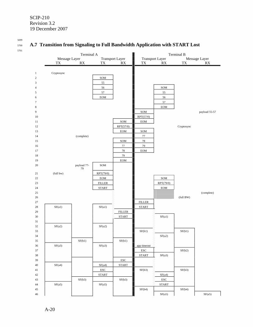
SCIP-210 Revision 3.2 19 December 2007
A-20
5699
A.7 Transition from Signaling to Full Bandwidth Application with START Lost 5700
5701 Terminal A Terminal B Message Layer Transport Layer Transport Layer Message Layer TX RX TX RX TX RX TX RX
1 Cryptosync
2 SOM
3 55
4 56 SOM
5 57 55
6 EOM 56
7 57
8 EOM
9 SOM payload 55-57
10 RPT(57/0)
11 SOM EOM
12 RPT(57/0) Cryptosync
13 EOM SOM
14 (complete) 77
15 SOM 78
16 77 79
17 78 EOM
18 79
19 EOM
20 payload 77-79
SOM
21 (full bw) RPT(79/0)
22 EOM SOM
23 FILLER RPT(79/0)
24 START EOM
25 (complete) 26 (full BW)
27 FILLER
28 SF(a1) SF(a1) START
29 FILLER
30 START SF(a1)
31
32 SF(a2) SF(a2)
33 SF(b1) SF(b1)
34 SF(a2)
35 SF(b1) SF(b1)
36 SF(a3) SF(a3) app timeout
37 ESC SF(b2)
38 START SF(a3)
39 ESC
40 SF(a4) SF(a4) START
41 ESC SF(b3) SF(b3)
42 START SF(a4)
43 SF(b3) SF(b3) ESC
44 SF(a5) SF(a5) START
45 SF(b4) SF(b4)
46 SF(a5) SF(a5)
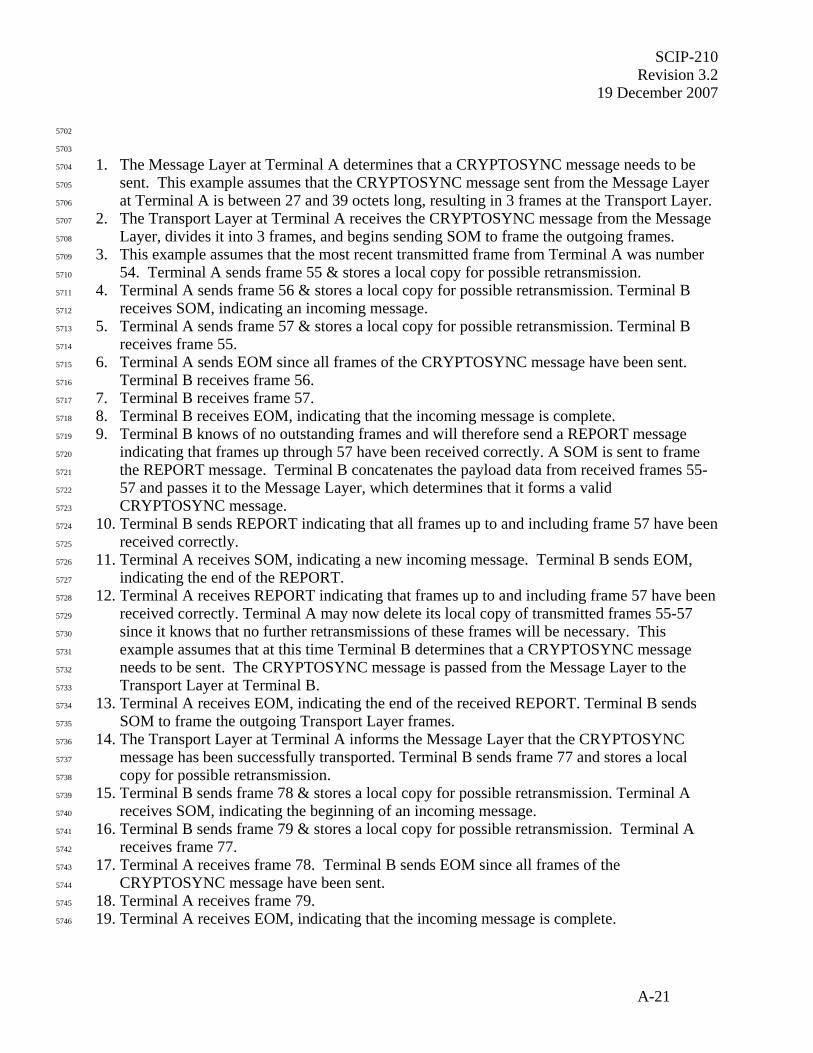
SCIP-210 Revision 3.2
19 December 2007
A-21
5702
5703
1. The Message Layer at Terminal A determines that a CRYPTOSYNC message needs to be 5704
sent. This example assumes that the CRYPTOSYNC message sent from the Message Layer 5705
at Terminal A is between 27 and 39 octets long, resulting in 3 frames at the Transport Layer. 5706
2. The Transport Layer at Terminal A receives the CRYPTOSYNC message from the Message 5707
Layer, divides it into 3 frames, and begins sending SOM to frame the outgoing frames. 5708
3. This example assumes that the most recent transmitted frame from Terminal A was number 5709
54. Terminal A sends frame 55 & stores a local copy for possible retransmission. 5710
4. Terminal A sends frame 56 & stores a local copy for possible retransmission. Terminal B 5711
receives SOM, indicating an incoming message. 5712
5. Terminal A sends frame 57 & stores a local copy for possible retransmission. Terminal B 5713
receives frame 55. 5714
6. Terminal A sends EOM since all frames of the CRYPTOSYNC message have been sent. 5715
Terminal B receives frame 56. 5716
7. Terminal B receives frame 57. 5717
8. Terminal B receives EOM, indicating that the incoming message is complete. 5718
9. Terminal B knows of no outstanding frames and will therefore send a REPORT message 5719
indicating that frames up through 57 have been received correctly. A SOM is sent to frame 5720
the REPORT message. Terminal B concatenates the payload data from received frames 55-5721
57 and passes it to the Message Layer, which determines that it forms a valid 5722
CRYPTOSYNC message. 5723
10. Terminal B sends REPORT indicating that all frames up to and including frame 57 have been 5724
received correctly. 5725
11. Terminal A receives SOM, indicating a new incoming message. Terminal B sends EOM, 5726
indicating the end of the REPORT. 5727
12. Terminal A receives REPORT indicating that frames up to and including frame 57 have been 5728
received correctly. Terminal A may now delete its local copy of transmitted frames 55-57 5729
since it knows that no further retransmissions of these frames will be necessary. This 5730
example assumes that at this time Terminal B determines that a CRYPTOSYNC message 5731
needs to be sent. The CRYPTOSYNC message is passed from the Message Layer to the 5732
Transport Layer at Terminal B. 5733
13. Terminal A receives EOM, indicating the end of the received REPORT. Terminal B sends 5734
SOM to frame the outgoing Transport Layer frames. 5735
14. The Transport Layer at Terminal A informs the Message Layer that the CRYPTOSYNC 5736
message has been successfully transported. Terminal B sends frame 77 and stores a local 5737
copy for possible retransmission. 5738
15. Terminal B sends frame 78 & stores a local copy for possible retransmission. Terminal A 5739
receives SOM, indicating the beginning of an incoming message. 5740
16. Terminal B sends frame 79 & stores a local copy for possible retransmission. Terminal A 5741
receives frame 77. 5742
17. Terminal A receives frame 78. Terminal B sends EOM since all frames of the 5743
CRYPTOSYNC message have been sent. 5744
18. Terminal A receives frame 79. 5745
19. Terminal A receives EOM, indicating that the incoming message is complete. 5746
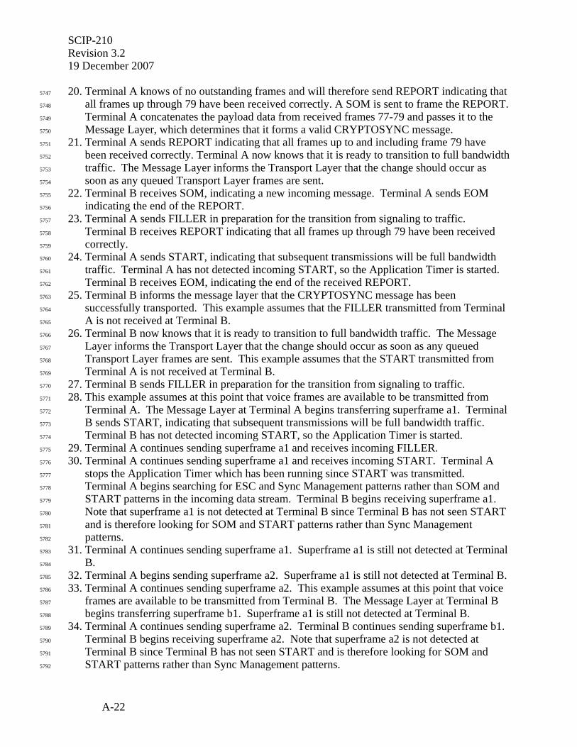
SCIP-210 Revision 3.2 19 December 2007
A-22
20. Terminal A knows of no outstanding frames and will therefore send REPORT indicating that 5747
all frames up through 79 have been received correctly. A SOM is sent to frame the REPORT. 5748
Terminal A concatenates the payload data from received frames 77-79 and passes it to the 5749
Message Layer, which determines that it forms a valid CRYPTOSYNC message. 5750
21. Terminal A sends REPORT indicating that all frames up to and including frame 79 have 5751
been received correctly. Terminal A now knows that it is ready to transition to full bandwidth 5752
traffic. The Message Layer informs the Transport Layer that the change should occur as 5753
soon as any queued Transport Layer frames are sent. 5754
22. Terminal B receives SOM, indicating a new incoming message. Terminal A sends EOM 5755
indicating the end of the REPORT. 5756
23. Terminal A sends FILLER in preparation for the transition from signaling to traffic. 5757
Terminal B receives REPORT indicating that all frames up through 79 have been received 5758
correctly. 5759
24. Terminal A sends START, indicating that subsequent transmissions will be full bandwidth 5760
traffic. Terminal A has not detected incoming START, so the Application Timer is started. 5761
Terminal B receives EOM, indicating the end of the received REPORT. 5762
25. Terminal B informs the message layer that the CRYPTOSYNC message has been 5763
successfully transported. This example assumes that the FILLER transmitted from Terminal 5764
A is not received at Terminal B. 5765
26. Terminal B now knows that it is ready to transition to full bandwidth traffic. The Message 5766
Layer informs the Transport Layer that the change should occur as soon as any queued 5767
Transport Layer frames are sent. This example assumes that the START transmitted from 5768
Terminal A is not received at Terminal B. 5769
27. Terminal B sends FILLER in preparation for the transition from signaling to traffic. 5770
28. This example assumes at this point that voice frames are available to be transmitted from 5771
Terminal A. The Message Layer at Terminal A begins transferring superframe a1. Terminal 5772
B sends START, indicating that subsequent transmissions will be full bandwidth traffic. 5773
Terminal B has not detected incoming START, so the Application Timer is started. 5774
29. Terminal A continues sending superframe a1 and receives incoming FILLER. 5775
30. Terminal A continues sending superframe a1 and receives incoming START. Terminal A 5776
stops the Application Timer which has been running since START was transmitted. 5777
Terminal A begins searching for ESC and Sync Management patterns rather than SOM and 5778
START patterns in the incoming data stream. Terminal B begins receiving superframe a1. 5779
Note that superframe a1 is not detected at Terminal B since Terminal B has not seen START 5780
and is therefore looking for SOM and START patterns rather than Sync Management 5781
patterns. 5782
31. Terminal A continues sending superframe a1. Superframe a1 is still not detected at Terminal 5783
B. 5784
32. Terminal A begins sending superframe a2. Superframe a1 is still not detected at Terminal B. 5785
33. Terminal A continues sending superframe a2. This example assumes at this point that voice 5786
frames are available to be transmitted from Terminal B. The Message Layer at Terminal B 5787
begins transferring superframe b1. Superframe a1 is still not detected at Terminal B. 5788
34. Terminal A continues sending superframe a2. Terminal B continues sending superframe b1. 5789
Terminal B begins receiving superframe a2. Note that superframe a2 is not detected at 5790
Terminal B since Terminal B has not seen START and is therefore looking for SOM and 5791
START patterns rather than Sync Management patterns. 5792
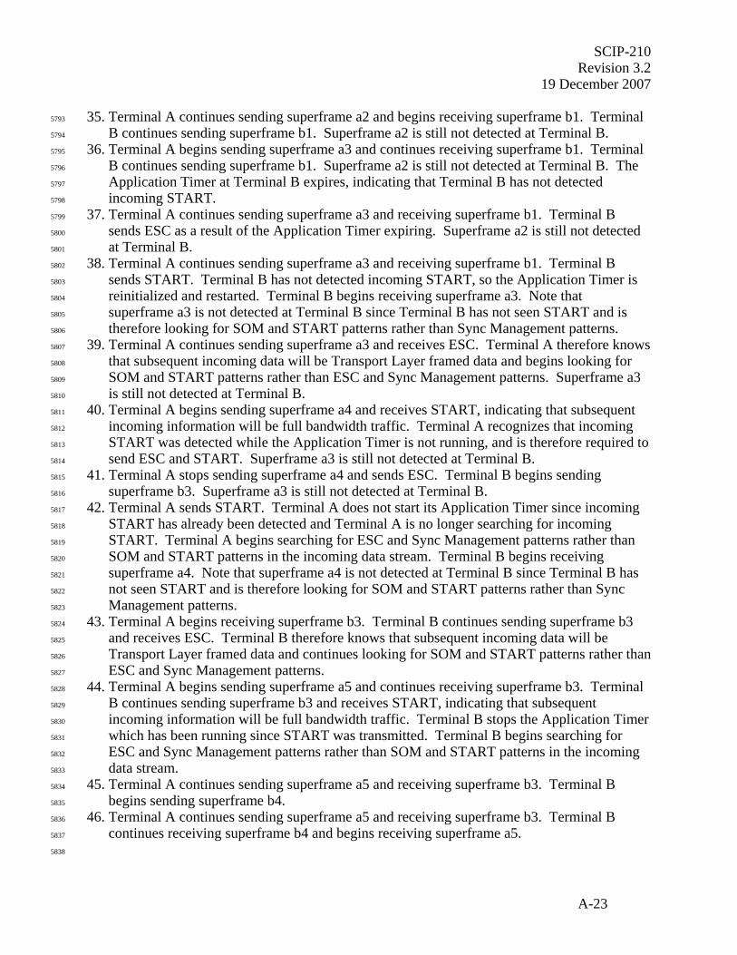
SCIP-210 Revision 3.2
19 December 2007
A-23
35. Terminal A continues sending superframe a2 and begins receiving superframe b1. Terminal 5793
B continues sending superframe b1. Superframe a2 is still not detected at Terminal B. 5794
36. Terminal A begins sending superframe a3 and continues receiving superframe b1. Terminal 5795
B continues sending superframe b1. Superframe a2 is still not detected at Terminal B. The 5796
Application Timer at Terminal B expires, indicating that Terminal B has not detected 5797
incoming START. 5798
37. Terminal A continues sending superframe a3 and receiving superframe b1. Terminal B 5799
sends ESC as a result of the Application Timer expiring. Superframe a2 is still not detected 5800
at Terminal B. 5801
38. Terminal A continues sending superframe a3 and receiving superframe b1. Terminal B 5802
sends START. Terminal B has not detected incoming START, so the Application Timer is 5803
reinitialized and restarted. Terminal B begins receiving superframe a3. Note that 5804
superframe a3 is not detected at Terminal B since Terminal B has not seen START and is 5805
therefore looking for SOM and START patterns rather than Sync Management patterns. 5806
39. Terminal A continues sending superframe a3 and receives ESC. Terminal A therefore knows 5807
that subsequent incoming data will be Transport Layer framed data and begins looking for 5808
SOM and START patterns rather than ESC and Sync Management patterns. Superframe a3 5809
is still not detected at Terminal B. 5810
40. Terminal A begins sending superframe a4 and receives START, indicating that subsequent 5811
incoming information will be full bandwidth traffic. Terminal A recognizes that incoming 5812
START was detected while the Application Timer is not running, and is therefore required to 5813
send ESC and START. Superframe a3 is still not detected at Terminal B. 5814
41. Terminal A stops sending superframe a4 and sends ESC. Terminal B begins sending 5815
superframe b3. Superframe a3 is still not detected at Terminal B. 5816
42. Terminal A sends START. Terminal A does not start its Application Timer since incoming 5817
START has already been detected and Terminal A is no longer searching for incoming 5818
START. Terminal A begins searching for ESC and Sync Management patterns rather than 5819
SOM and START patterns in the incoming data stream. Terminal B begins receiving 5820
superframe a4. Note that superframe a4 is not detected at Terminal B since Terminal B has 5821
not seen START and is therefore looking for SOM and START patterns rather than Sync 5822
Management patterns. 5823
43. Terminal A begins receiving superframe b3. Terminal B continues sending superframe b3 5824
and receives ESC. Terminal B therefore knows that subsequent incoming data will be 5825
Transport Layer framed data and continues looking for SOM and START patterns rather than 5826
ESC and Sync Management patterns. 5827
44. Terminal A begins sending superframe a5 and continues receiving superframe b3. Terminal 5828
B continues sending superframe b3 and receives START, indicating that subsequent 5829
incoming information will be full bandwidth traffic. Terminal B stops the Application Timer 5830
which has been running since START was transmitted. Terminal B begins searching for 5831
ESC and Sync Management patterns rather than SOM and START patterns in the incoming 5832
data stream. 5833
45. Terminal A continues sending superframe a5 and receiving superframe b3. Terminal B 5834
begins sending superframe b4. 5835
46. Terminal A continues sending superframe a5 and receiving superframe b3. Terminal B 5836
continues receiving superframe b4 and begins receiving superframe a5. 5837
5838
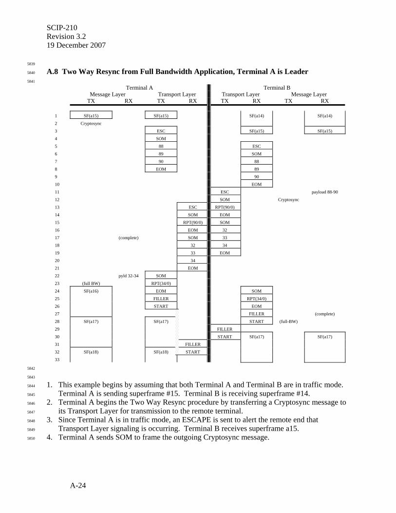
SCIP-210 Revision 3.2 19 December 2007
A-24
5839
A.8 Two Way Resync from Full Bandwidth Application, Terminal A is Leader 5840
5841
Terminal A Terminal B Message Layer Transport Layer Transport Layer Message Layer TX RX TX RX TX RX TX RX
1 SF(a15) SF(a15) SF(a14) SF(a14)
2 Cryptosync
3 ESC SF(a15) SF(a15)
4 SOM
5 88 ESC
6 89 SOM
7 90 88
8 EOM 89
9 90
10 EOM
11 ESC payload 88-90
12 SOM Cryptosync
13 ESC RPT(90/0)
14 SOM EOM
15 RPT(90/0) SOM
16 EOM 32
17 (complete) SOM 33
18 32 34
19 33 EOM
20 34
21 EOM
22 pyld 32-34 SOM
23 (full BW) RPT(34/0)
24 SF(a16) EOM SOM
25 FILLER RPT(34/0)
26 START EOM
27 FILLER (complete)
28 SF(a17) SF(a17) START (full-BW)
29 FILLER
30 START SF(a17) SF(a17)
31 FILLER
32 SF(a18) SF(a18) START
33
5842
5843
1. This example begins by assuming that both Terminal A and Terminal B are in traffic mode. 5844
Terminal A is sending superframe #15. Terminal B is receiving superframe #14. 5845
2. Terminal A begins the Two Way Resync procedure by transferring a Cryptosync message to 5846
its Transport Layer for transmission to the remote terminal. 5847
3. Since Terminal A is in traffic mode, an ESCAPE is sent to alert the remote end that 5848
Transport Layer signaling is occurring. Terminal B receives superframe a15. 5849
4. Terminal A sends SOM to frame the outgoing Cryptosync message. 5850
SCIP-210 Revision 3.2
19 December 2007
A-25
5. This example assumes that the Cryptosync message is between 27 and 39 bytes long, 5851
resulting in three frames at the Transport Layer, and that the most recently transmitted 5852
Transport Layer frame was #87. Frame 88 is therefore sent. Terminal B receives ESCAPE 5853
indicating the beginning of an incoming Transport Layer message. 5854
6. Terminal A sends frame 89. Terminal B receives the SOM. 5855
7. Terminal A sends frame 90. Terminal B receives frame 88. 5856
8. Terminal A sends EOM to frame the outgoing Cryptosync message. Terminal B receives 5857
frame 89. 5858
9. Terminal B receives frame 90. 5859
10. Terminal B receives EOM indicating the end of the incoming Transport Layer message. 5860
11. Terminal B knows of no outstanding frames and will therefore acknowledge frame 90 using a 5861
REPORT message. Terminal B sends ESCAPE to alert the remote end that Transport Layer 5862
signaling is occurring. Terminal B passes the payload information from frames 88 to 90 to 5863
the Message Layer, which determines that it is a valid Cryptosync message. 5864
12. Terminal B sends SOM to frame the REPORT message. This example assumes that 5865
Terminal B is ready to send Cryptosync at this point, so it is transferred to the Transport 5866
Layer. 5867
13. Terminal B sends REPORT indicating that frames through 90 have been received correctly. 5868
Terminal A receives ESCAPE indicating the beginning of an incoming Transport Layer 5869
message. 5870
14. Terminal A receives SOM indicating an incoming message. Terminal B sends EOM, 5871
framing the REPORT message. 5872
15. Terminal A receives REPORT. Terminal B sends SOM to frame the outgoing Cryptosync 5873
message. 5874
16. Terminal A receives EOM. This example assumes that the Cryptosync message is between 5875
27 and 39 bytes long, resulting in three frames at the Transport Layer, and that the most 5876
recently transmitted Transport Layer frame was #31. Frame 32 is therefore sent. 5877
17. The Transport Layer at Terminal A informs the Message Layer that the Cryptosync message 5878
has been successfully transported. Terminal A receives SOM indicating an incoming 5879
message. Terminal B sends frame 33. 5880
18. Terminal A receives frame 32. Terminal B sends frame 34. 5881
19. Terminal A receives frame 33. Terminal B sends EOM to frame the outgoing Cryptosync 5882
message. 5883
20. Terminal A receives frame 34. 5884
21. Terminal A receives EOM. 5885
22. Terminal A knows of no outstanding frames and will therefore acknowledge frame 34 using 5886
a REPORT message. SOM is sent to frame the REPORT. Terminal A passes the payload 5887
information from frames 32 to 34 to the Message Layer, which determines that it is a valid 5888
Cryptosync message. 5889
23. The Message Layer at Terminal A now knows that Cryptosync has been sent and received, 5890
so it informs the Transport Layer to transition back to traffic mode. Terminal A sends 5891
REPORT indicating that frames through 34 have been received correctly. 5892
24. The Message Layer at Terminal A begins passing superframes to the Transport Layer, which 5893
is still busy with Transport Layer signaling. Terminal A sends EOM to frame the REPORT. 5894
Terminal B receives SOM. 5895
SCIP-210 Revision 3.2 19 December 2007
A-26
25. Terminal A is now ready to transition to full bandwidth mode and sends FILLER since 5896
Cryptosync was the last message transferred. Terminal B receives REPORT. 5897
26. Terminal A sends START to complete the transition to full bandwidth mode. Terminal A 5898
starts the Application Timer since START has not been received. Terminal B receives EOM. 5899
27. Terminal B receives FILLER. The Transport Layer at Terminal B informs the Message 5900
Layer that the Cryptosync message has been successfully transported 5901
28. Terminal A begins sending superframe a17. Terminal B receives START. The Message 5902
Layer at Terminal B recognizes that Cryptosync has been received and sent and therefore 5903
instructs the Transport Layer to transition back to full bandwidth mode. 5904
29. Terminal A continues sending superframe a17. Terminal B sends FILLER in preparation for 5905
transitioning to full bandwidth mode. 5906
30. Terminal A continues sending superframe a17. Terminal B sends START to complete the 5907
transition to full bandwidth mode. The Application Timer at Terminal B is not started since 5908
incoming START has already been detected. Terminal B begins receiving superframe a17. 5909
31. Terminal A continues sending superframe a17 and receives incoming FILLER. Terminal B 5910
continues receiving superframe a17. 5911
32. Terminal A begins sending superframe a18 and receives incoming START. The Application 5912
Timer at Terminal A is stopped. Terminal B continues receiving superframe a17. 5913
33. Terminal A continues sending superframe a18. Terminal B continues receiving superframe 5914
a17. 5915
5916
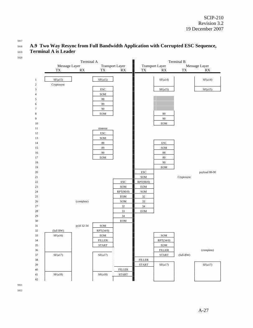
SCIP-210 Revision 3.2
19 December 2007
A-27
5917
A.9 Two Way Resync from Full Bandwidth Application with Corrupted ESC Sequence, 5918
Terminal A is Leader 5919
5920
Terminal A Terminal B Message Layer Transport Layer Transport Layer Message Layer TX RX TX RX TX RX TX RX
1 SF(a15) SF(a15) SF(a14) SF(a14)
2 Cryptosync
3 ESC SF(a15) SF(a15)
4 SOM
5 88
6 89
7 90
8 EOM 89
9 90
10 EOM
11 timeout
12 ESC
13 SOM
14 88 ESC
15 89 SOM
16 90 88
17 EOM 89
18 90
19 EOM
20 ESC payload 88-90
21 SOM Cryptosync
22 ESC RPT(90/0)
23 SOM EOM
24 RPT(90/0) SOM
25 EOM 32
26 (complete) SOM 33
27 32 34
28 33 EOM
29 34
30 EOM
31 pyld 32-34 SOM
32 (full BW) RPT(34/0)
33 SF(a16) EOM SOM
34 FILLER RPT(34/0)
35 START EOM
36 FILLER (complete)
37 SF(a17) SF(a17) START (full-BW)
38 FILLER
39 START SF(a17) SF(a17)
40 FILLER
41 SF(a18) SF(a18) START
42
5921
5922

SCIP-210 Revision 3.2 19 December 2007
A-28
1. This example begins by assuming that both Terminal A and Terminal B are in traffic mode. 5923
Terminal A is sending superframe #15. Terminal B is receiving superframe #14. 5924
2. Terminal A begins the Two Way Resync procedure by transferring a Cryptosync message to 5925
its Transport Layer for transmission to the remote terminal. 5926
3. Since Terminal A is in traffic mode, an ESCAPE is sent to alert the remote end that 5927
Transport Layer signaling is occurring. Terminal B receives superframe a15. 5928
4. Terminal A sends SOM to frame the outgoing Cryptosync message. 5929
5. This example assumes that the Cryptosync message is between 27 and 39 bytes long, 5930
resulting in three frames at the Transport Layer, and that the most recently transmitted 5931
Transport Layer frame was #87. Frame 88 is therefore sent. Terminal B should receive ESC 5932
at this point, but this example assumes that the ESC is lost. 5933
6. Terminal A sends frame 89. Terminal B should receive SOM but this example assumes that 5934
it is lost. 5935
7. Terminal A sends frame 90. Terminal B should receive frame 88 but this example assumes 5936
that it is lost. 5937
8. Terminal A sends EOM to frame the outgoing Cryptosync. Terminal B receives frame 89 5938
but it is not detected since Terminal B missed ESC and is therefore searching for ESC and 5939
Sync Management frames. 5940
9. Terminal B receives frame 90 but it is not detected since Terminal B missed ESC and is 5941
therefore searching for ESC and Sync Management frames. 5942
10. Terminal B receives EOM but it is not detected since Terminal B missed ESC and is 5943
therefore searching for ESC and Sync Management frames. 5944
11. The Retransmission Timer at Terminal A eventually times out and forces Terminal A to 5945
resend the previous frames. 5946
12. Since the previous Transport Layer transmission from Terminal A began with ESCAPE, an 5947
ESCAPE is again sent. 5948
13. Terminal A sends SOM to frame the outgoing Cryptosync message retransmission. 5949
14. Terminal B receives ESCAPE indicating the beginning of an incoming Transport Layer 5950
message. Terminal A sends frame 88 5951
15. Terminal A sends frame 89. Terminal B receives the SOM. 5952
16. Terminal A sends frame 90. Terminal B receives frame 88. 5953
17. Terminal A sends EOM to frame the outgoing Cryptosync message. Terminal B receives 5954
frame 89. 5955
18. Terminal B receives frame 90. 5956
19. Terminal B receives EOM indicating the end of the incoming Transport Layer message. 5957
20. Terminal B knows of no outstanding frames and will therefore acknowledge frame 90 using a 5958
REPORT message. Terminal B sends ESCAPE to alert the remote end that Transport Layer 5959
signaling is occurring. Terminal B passes the payload information from frames 88 to 90 to 5960
the Message Layer, which determines that it is a valid Cryptosync message. 5961
21. Terminal B sends SOM to frame the REPORT message. This example assumes that 5962
Terminal B is ready to send Cryptosync at this point, so it is transferred to the Transport 5963
Layer. 5964
22. Terminal B sends REPORT indicating that frames through 90 have been received correctly. 5965
Terminal A receives ESCAPE indicating the beginning of an incoming Transport Layer 5966
message. 5967
SCIP-210 Revision 3.2
19 December 2007
A-29
23. Terminal A receives SOM indicating an incoming message. Terminal B sends EOM, 5968
framing the REPORT message. 5969
24. Terminal A receives REPORT. Terminal B sends SOM to frame the outgoing Cryptosync 5970
message. 5971
25. Terminal A receives EOM. This example assumes that the Cryptosync message is between 5972
27 and 39 bytes long, resulting in three frames at the Transport Layer, and that the most 5973
recently transmitted Transport Layer frame was #31. Frame 32 is therefore sent. 5974
26. The Transport Layer at Terminal A informs the Message Layer that the Cryptosync message 5975
has been successfully transported. Terminal A receives SOM indicating an incoming 5976
message. Terminal B sends frame 33. 5977
27. Terminal A receives frame 32. Terminal B sends frame 34. 5978
28. Terminal A receives frame 33. Terminal B sends EOM to frame the outgoing Cryptosync 5979
message. 5980
29. Terminal A receives frame 34. 5981
30. Terminal A receives EOM. 5982
31. Terminal A knows of no outstanding frames and will therefore acknowledge frame 34 using 5983
a REPORT message. SOM is sent to frame the REPORT. Terminal A passes the payload 5984
information from frames 32 to 34 to the Message Layer, which determines that it is a valid 5985
Cryptosync message. 5986
32. The Message Layer at Terminal A now knows that Cryptosync has been sent and received, 5987
so it informs the Transport Layer to transition back to traffic mode. Terminal A sends 5988
REPORT indicating that frames through 34 have been received correctly. 5989
33. The Message Layer at Terminal A begins passing superframes to the Transport Layer, which 5990
is still busy with Transport Layer signaling. Terminal A sends EOM to frame the REPORT. 5991
Terminal B receives SOM. 5992
34. Terminal A is now ready to transition to full bandwidth mode and sends FILLER since 5993
Cryptosync was the last message transferred. Terminal B receives REPORT. 5994
35. Terminal A sends START to complete the transition to full bandwidth mode. Terminal A 5995
starts the Application Timer since START has not been received. Terminal B receives EOM. 5996
36. Terminal B receives FILLER. The Transport Layer at Terminal B informs the Message 5997
Layer that the Cryptosync message has been successfully transported 5998
37. Terminal A begins sending superframe a17. Terminal B receives START. The Message 5999
Layer at Terminal B recognizes that Cryptosync has been received and sent and therefore 6000
instructs the Transport Layer to transition back to full bandwidth mode. 6001
38. Terminal A continues sending superframe a17. Terminal B sends FILLER in preparation for 6002
transitioning to full bandwidth mode. 6003
39. Terminal A continues sending superframe a17. Terminal B sends START to complete the 6004
transition to full bandwidth mode. The Application Timer at Terminal B is not started since 6005
incoming START has already been detected. Terminal B begins receiving superframe a17. 6006
40. Terminal A continues sending superframe a17 and receives incoming FILLER. Terminal B 6007
continues receiving superframe a17. 6008
41. Terminal A begins sending superframe a18 and receives incoming START. The Application 6009
Timer at Terminal A is stopped. Terminal B continues receiving superframe a17. 6010
42. Terminal A continues sending superframe a18. Terminal B continues receiving superframe 6011
a17. 6012
6013
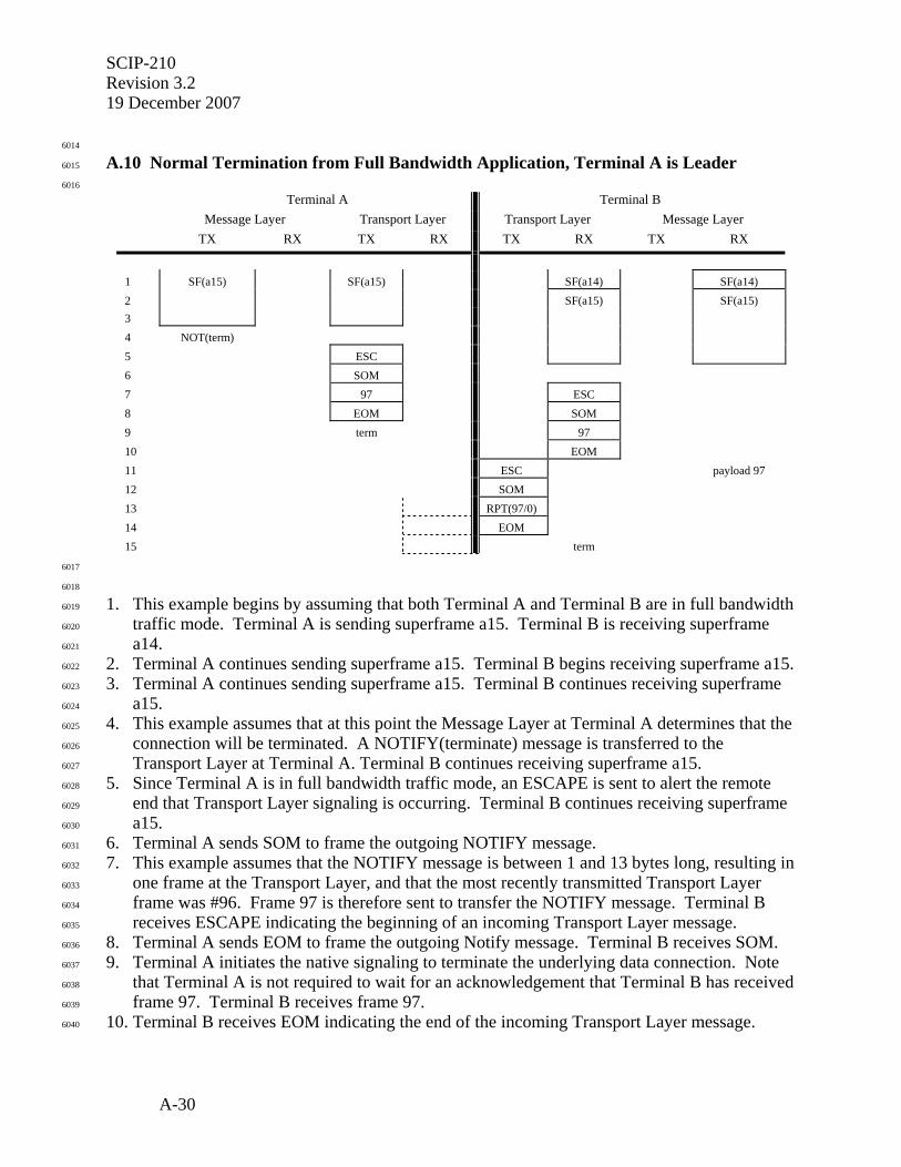
SCIP-210 Revision 3.2 19 December 2007
A-30
6014
A.10 Normal Termination from Full Bandwidth Application, Terminal A is Leader 6015
6016
Terminal A Terminal B
Message Layer Transport Layer Transport Layer Message Layer
TX RX TX RX TX RX TX RX
1 SF(a15) SF(a15) SF(a14) SF(a14) 2 SF(a15) SF(a15) 3 4 NOT(term) 5 ESC 6 SOM 7 97 ESC 8 EOM SOM 9 term 97 10 EOM 11 ESC payload 97 12 SOM 13 RPT(97/0) 14 EOM 15 term
6017
6018
1. This example begins by assuming that both Terminal A and Terminal B are in full bandwidth 6019
traffic mode. Terminal A is sending superframe a15. Terminal B is receiving superframe 6020
a14. 6021
2. Terminal A continues sending superframe a15. Terminal B begins receiving superframe a15. 6022
3. Terminal A continues sending superframe a15. Terminal B continues receiving superframe 6023
a15. 6024
4. This example assumes that at this point the Message Layer at Terminal A determines that the 6025
connection will be terminated. A NOTIFY(terminate) message is transferred to the 6026
Transport Layer at Terminal A. Terminal B continues receiving superframe a15. 6027
5. Since Terminal A is in full bandwidth traffic mode, an ESCAPE is sent to alert the remote 6028
end that Transport Layer signaling is occurring. Terminal B continues receiving superframe 6029
a15. 6030
6. Terminal A sends SOM to frame the outgoing NOTIFY message. 6031
7. This example assumes that the NOTIFY message is between 1 and 13 bytes long, resulting in 6032
one frame at the Transport Layer, and that the most recently transmitted Transport Layer 6033
frame was #96. Frame 97 is therefore sent to transfer the NOTIFY message. Terminal B 6034
receives ESCAPE indicating the beginning of an incoming Transport Layer message. 6035
8. Terminal A sends EOM to frame the outgoing Notify message. Terminal B receives SOM. 6036
9. Terminal A initiates the native signaling to terminate the underlying data connection. Note 6037
that Terminal A is not required to wait for an acknowledgement that Terminal B has received 6038
frame 97. Terminal B receives frame 97. 6039
10. Terminal B receives EOM indicating the end of the incoming Transport Layer message. 6040
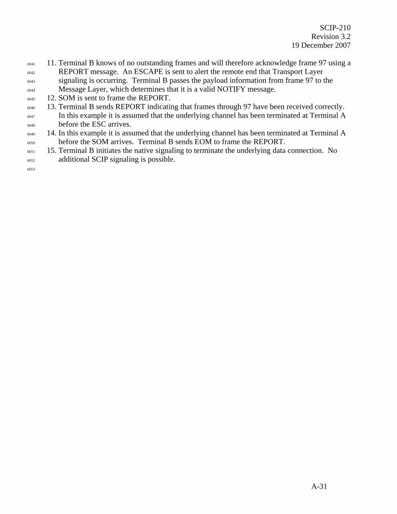
SCIP-210 Revision 3.2
19 December 2007
A-31
11. Terminal B knows of no outstanding frames and will therefore acknowledge frame 97 using a 6041
REPORT message. An ESCAPE is sent to alert the remote end that Transport Layer 6042
signaling is occurring. Terminal B passes the payload information from frame 97 to the 6043
Message Layer, which determines that it is a valid NOTIFY message. 6044
12. SOM is sent to frame the REPORT. 6045
13. Terminal B sends REPORT indicating that frames through 97 have been received correctly. 6046
In this example it is assumed that the underlying channel has been terminated at Terminal A 6047
before the ESC arrives. 6048
14. In this example it is assumed that the underlying channel has been terminated at Terminal A 6049
before the SOM arrives. Terminal B sends EOM to frame the REPORT. 6050
15. Terminal B initiates the native signaling to terminate the underlying data connection. No 6051
additional SCIP signaling is possible. 6052
6053
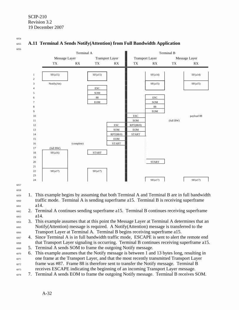
SCIP-210 Revision 3.2 19 December 2007
A-32
6054
A.11 Terminal A Sends Notify(Attention) from Full Bandwidth Application 6055
6056
Terminal A Terminal B
Message Layer Transport Layer Transport Layer Message Layer
TX RX TX RX TX RX TX RX
1 SF(a15) SF(a15) SF(a14) SF(a14) 2
3 Notify(Att) SF(a15) SF(a15)
4 ESC
5 SOM
6 88 ESC
7 EOM SOM
8 88
9 EOM
10 ESC payload 88
11 SOM (full BW)
12 ESC RPT(88/0)
13 SOM EOM
14 RPT(88/0) START
15 EOM
16 (complete) START
17 (full BW)
18 SF(a16) START
19
20 START
21
22 SF(a17) SF(a17) 23
24 SF(a17) SF(a17)
6057
6058
1. This example begins by assuming that both Terminal A and Terminal B are in full bandwidth 6059
traffic mode. Terminal A is sending superframe a15. Terminal B is receiving superframe 6060
a14. 6061
2. Terminal A continues sending superframe a15. Terminal B continues receiving superframe 6062
a14. 6063
3. This example assumes that at this point the Message Layer at Terminal A determines that an 6064
Notify(Attention) message is required. A Notify(Attention) message is transferred to the 6065
Transport Layer at Terminal A. Terminal B begins receiving superframe a15. 6066
4. Since Terminal A is in full bandwidth traffic mode, ESCAPE is sent to alert the remote end 6067
that Transport Layer signaling is occurring. Terminal B continues receiving superframe a15. 6068
5. Terminal A sends SOM to frame the outgoing Notify message. 6069
6. This example assumes that the Notify message is between 1 and 13 bytes long, resulting in 6070
one frame at the Transport Layer, and that the most recently transmitted Transport Layer 6071
frame was #87. Frame 88 is therefore sent to transfer the Notify message. Terminal B 6072
receives ESCAPE indicating the beginning of an incoming Transport Layer message. 6073
7. Terminal A sends EOM to frame the outgoing Notify message. Terminal B receives SOM. 6074

SCIP-210 Revision 3.2
19 December 2007
A-33
8. Terminal B receives frame 88. 6075
9. Terminal B receives EOM indicating the end of the incoming Transport Layer message. 6076
10. Terminal B knows of no outstanding frames and will therefore acknowledge frame 88 using a 6077
REPORT message. ESCAPE is sent to alert the remote end that Transport Layer signaling is 6078
occurring. Terminal B passes the payload information from frame 88 to the Message Layer, 6079
which determines that it is a valid Notify(Attention) message. 6080
11. Terminal B sends SOM to frame the outgoing REPORT. The Message Layer at Terminal B 6081
indicates to the Transport Layer that the full bandwidth traffic mode is to resume. 6082
12. Terminal A receives ESCAPE indicating the beginning of an incoming Transport Layer 6083
message. Terminal B sends REPORT indicating that frames through 88 have been received 6084
correctly. 6085
13. Terminal A receives SOM, indicating an incoming message. Terminal B sends EOM, 6086
framing the outgoing REPORT. 6087
14. Terminal A receives REPORT. Terminal B sends START to resume the full bandwidth 6088
traffic application. Note that FILLER is not required since Cryptosync was not transferred. 6089
Terminal B has not received incoming START, so the Application Timer is started. 6090
15. Terminal A receives EOM. 6091
16. The Transport Layer at Terminal A informs the Message Layer that the Notify(Attention) 6092
message has been successfully transported. 6093
17. The Message Layer at Terminal A indicates to the Transport Layer that the full bandwidth 6094
traffic mode is to resume. 6095
18. Terminal A sends START to reinitiate traffic. The Application Timer is not started since 6096
incoming START has already been detected. 6097
19. The Transport Layer at Terminal A waits for the beginning of a superframe to begin full 6098
bandwidth transmission. 6099
20. Terminal B receives START indicating incoming traffic. The Application Timer is now 6100
stopped. 6101
21. The Transport Layer at Terminal A waits for the beginning of a superframe to begin full 6102
bandwidth transmission. 6103
22. Terminal A begins sending superframe a17. 6104
23. Terminal A continues sending superframe a17. 6105
24. Terminal A continues sending superframe a17. Terminal B begins receiving superframe a17. 6106
6107

SCIP-210 Revision 3.2 19 December 2007
A-34
6108
6109
6110
6111
6112
6113
6114
6115
6116
6117
6118
6119
6120
6121
6122
6123
6124
6125
6126
6127
6128
THIS PAGE INTENTIONALLY LEFT BLANK. 6129
6130
6131
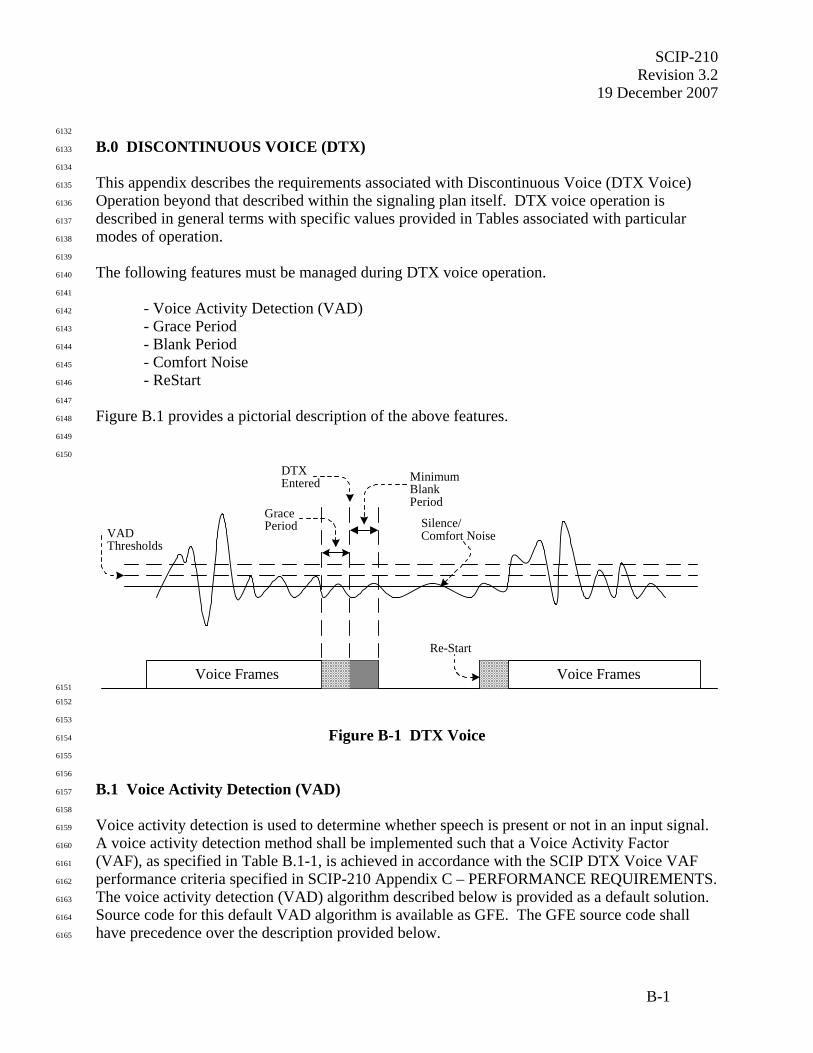
SCIP-210 Revision 3.2
19 December 2007
B-1
6132
B.0 DISCONTINUOUS VOICE (DTX) 6133
6134
This appendix describes the requirements associated with Discontinuous Voice (DTX Voice) 6135
Operation beyond that described within the signaling plan itself. DTX voice operation is 6136
described in general terms with specific values provided in Tables associated with particular 6137
modes of operation. 6138
6139
The following features must be managed during DTX voice operation. 6140
6141
- Voice Activity Detection (VAD) 6142
- Grace Period 6143
- Blank Period 6144
- Comfort Noise 6145
- ReStart 6146
6147
Figure B.1 provides a pictorial description of the above features. 6148
6149
6150
VADThresholds
DTXEntered
GracePeriod
MinimumBlankPeriod
Silence/Comfort Noise
Re-Start
Voice Frames Voice Frames6151
6152
6153
Figure B-1 DTX Voice 6154
6155
6156
B.1 Voice Activity Detection (VAD) 6157
6158
Voice activity detection is used to determine whether speech is present or not in an input signal. 6159
A voice activity detection method shall be implemented such that a Voice Activity Factor 6160
(VAF), as specified in Table B.1-1, is achieved in accordance with the SCIP DTX Voice VAF 6161
performance criteria specified in SCIP-210 Appendix C – PERFORMANCE REQUIREMENTS. 6162
The voice activity detection (VAD) algorithm described below is provided as a default solution. 6163
Source code for this default VAD algorithm is available as GFE. The GFE source code shall 6164
have precedence over the description provided below. 6165

SCIP-210 Revision 3.2 19 December 2007
B-2
6166
6167
Table B.1-1 DTX VAF Values 6168
6169
Voice Mode
Voice Activity Factor
MELP Blank and Burst
< 0.6
6170
6171
Editor's Note: MELP Blank and Burst VAF of < 0.6 is relative to testing performed with test vectors provided by the Government. The VAF test vectors are available from the International ICWG Web site (http://198.184.128.72/iicwg) or on disk from NSA.
6172
6173
B.2 Default Voice Activity Detection (VAD) Algorithm 6174
6175
The following VAD is provided as a default solution. The GFE source code shall have 6176
precedence over the description provided below. The VAD uses the energy level of the input 6177
speech to determine whether speech or silence is present. The equation 6178
6179
( )( )FrameSize
AAEnergyH ×= 6180
6181
is used to calculate the energy of each speech frame, where A is a vector of one frame of input 6182
data, AH is the complex conjugate transpose of A, and FrameSize is the number of samples per 6183
vocoder frame. The minimum (Low RMS) and maximum (High RMS) energy levels are set 6184
based on the energy of the input vector. These values are used to calculate an energy threshold 6185
that is compared to the present frame’s energy level. The equation 6186
6187
( ) ( ),07.0 LowRMSKHighRMSThreshold ×+×= 6188
6189
where K is a constant, is used to calculate the energy threshold. If frame’s energy is less than the 6190
threshold, then the frame is marked as silence. If more than four consecutive frames of speech 6191
have energy levels less than the threshold, then it is determined that silence is detected and 6192
comfort noise is written out. This mode continues until an input vector’s energy level is above 6193
the threshold. 6194

SCIP-210 Revision 3.2
19 December 2007
B-3
6195
In order to compensate for low energy anomalies, the minimum energy value is slowly increased 6196
each time through the loop by a defined delta, 6197
6198
.DeltaUpLowRMSLowRMS ×= 6199
6200
DeltaUp is initially set to 1.01 and is adjusted depending on whether the LowRMS is reset or not 6201
as follows 6202
6203
.0001.1×= DeltaUpDeltaUp 6204
6205
Editor's Note: Source code for the default VAD is available, as GFE, from the International ICWG Web site (http://198.184.128.72/iicwg) or on disk from NSA.
6206
6207
B.3 Grace Period 6208
6209
The Grace Period is a variable period of silence/background noise that is transmitted after silence 6210
is detected and before DTX mode is entered. 6211
6212
The Grace Period shall contain a minimum of two (2) vocoder frames. These vocoder frames 6213
shall be uniquely identifiable as silence. The information being transmitted in the Grace Period 6214
vocoder frames shall contain vocoder compatible parameters, such that processing these frames 6215
through the vocoder does not produce unacceptable noise. 6216
6217
For MELP Blank and Burst, the Grace Period shall be populated with MELP vocoder frames as 6218
defined in Table B.3-1 – MELP Comfort Noise Parameter Values. All MELP vocoder parameter 6219
values shall be set to zero (0) except msvq[0], gain[1] and sync. 6220
6221

SCIP-210 Revision 3.2 19 December 2007
B-4
6222
Table B.3-1 MELP Comfort Noise Parameter Values 6223
6224
MELP Parameter Value msvq[0] (line spectral frequencies) * See Note (1) msvq[1] (line spectral frequencies) Set to 0 msvq[2] (line spectral frequencies) Set to 0 msvq[3] (line spectral frequencies) Set to 0 fsvq (Fourier magnitudes) Set to 0 gain[0] (gain) Set to 0 gain[1] (gain) * See Note (1) pitch (pitch – overall voicing) Set to 0 bp (bandpass voicing) Set to 0 af (aperiodic flag/jitter index) Set to 0 sync (sync bit) Continue Alternations
6225
Notes: 6226
1. The default value shall be the respective parameter value from the previous 6227
vocoder frame. It is recommended that msvq[0] and gain[1] values be derived 6228
by averaging the respective parameters from some number of previous vocoder 6229
frames. 6230
6231
6232
B.4 Blank Period 6233
6234
The Blank Period is defined as a variable amount of time that DTX mode (no voice traffic 6235
transmissions) must be executed once it has been entered. 6236
6237
The Blank Period shall have a minimum duration equivalent to “n” vocoder frames as defined in 6238
Table B.4-1. 6239
6240
6241
Table B.4-1 Blank Period Values 6242
6243
Voice Mode
Blank Period “n”
MELP Blank and Burst 2
6244

SCIP-210 Revision 3.2
19 December 2007
B-5
6245
B.5 Comfort Noise 6246
6247
Comfort noise is generated so that a user is not annoyed by the disappearance of background 6248
noise during periods of silence. It is recommended that comfort noise be generated and provided 6249
to the user at the receiver. 6250
6251
For MELP Blank and Burst, the MELP vocoder frame defined in Table B.3-1 shall be used as 6252
the comfort noise value. The default comfort noise method shall be to repeat the vocoder frame 6253
from the Grace Period at the receiver. It is recommended that the averaged values of these 6254
parameters be computed at the transmitter and inserted as the Grace Period frames. 6255
6256
Editor's Note: Generation of comfort noise for GSM is specified in GSM standards 6.12, 6.22 and 6.62.
6257
6258
B.6 Re-Start 6259
6260
Upon detection of voice activity, voice traffic mode shall be re-entered, after fulfilling the 6261
minimum Blank Period, by sending a Re-Start message. 6262
6263
For MELP Blank and Burst, the Re-Start message shall be the Sync Management Frame as 6264
defined in SCIP-210 Section 3.3.1.1. 6265
6266
Upon the Re-Start of voice traffic, there are three alternative ways to manage the onset of voice 6267
activity and associated voice quality issues: 6268
6269
- BUFFER/DELAY initial vocoder frame while sync management frame is sent; 6270
- CLIP initial vocoder frame and substitute sync management frame; and 6271
- Skew Time by comparing several vocoder frames and delete, prior to encryption, the 6272
least useful vocoder frame to make room for the Sync Management frame. 6273
6274
For the BUFFER/DELAY option, a maximum delay equivalent to one (1) vocoder frame is 6275
permitted. 6276
6277

SCIP-210 Revision 3.2 19 December 2007
B-6
6278
6279
6280
6281
6282
6283
6284
6285
6286
6287
6288
6289
6290
6291
6292
6293
6294
6295
6296
6297
6298
THIS PAGE INTENTIONALLY LEFT BLANK. 6299
6300
6301
6302

SCIP-210 Revision 3.2
19 December 2007
C-1
6303
C.0 PERFORMANCE 6304
6305
C.1 DTX Voice 6306
6307
The Voice Activity Detection algorithm shall provide a Voice Activity Factor (VAF) as defined 6308
in SCIP-210 Appendix B, Table B.1-1 – DTX VAF Values. 6309
6310
C.1.1 MELP Blank and Burst 6311
6312
The VAF of < 0.6 shall be measured as the percentage of all frames transmitted, including voice, 6313
silence (e.g. during silence detection period) and Grace Period frames, while processing the 6314
Government provided test vectors. The test vectors are heli_mp_rh.spd, jeep_ch_vw.spd and 6315
off_ch2_vw.spd. These test vectors are available from the International ICWG Web site 6316
(http://198.184.128.72/iicwg) or on disk from NSA. 6317
6318
6319
6320
Related Documents