NOZZLES Nozzles .......................................................................................................................................................... 1 Nozzle flow equations ............................................................................................................................... 3 Choked flow .......................................................................................................................................... 4 Area ratio............................................................................................................................................... 5 Converging nozzle ................................................................................................................................ 6 Converging-diverging nozzle................................................................................................................ 8 Discontinuities in nozzle flow: normal and oblique shocks, expansion fans. Mach diamonds .......... 12 Aerospike nozzle ................................................................................................................................. 16 NOZZLES A nozzle (from nose, meaning 'small spout') is a tube of varying cross-sectional area (usually axisymmetric) aiming at increasing the speed of an outflow, and controlling its direction and shape. Nozzle flow always generates forces associated to the change in flow momentum, as we can feel by hand- holding a hose and opening the tap. In the simplest case of a rocket nozzle, relative motion is created by ejecting mass from a chamber backwards through the nozzle, with the reaction forces acting mainly on the opposite chamber wall, with a small contribution from nozzle walls. As important as the propeller is to shaft-engine propulsions, so it is the nozzle to jet propulsion, since it is in the nozzle that thermal energy (or any other kind of high-pressure energy source) transforms into kinetic energy of the exhaust, and its associated linear momentum producing thrust. The flow in a nozzle is very rapid (and thus adiabatic to a first approximation), and with very little frictional loses (because the flow is nearly one-dimensional, with a favourable pressure gradient except if shock waves form, and nozzles are relatively short), so that the isentropic model all along the nozzle is good enough for preliminary design. The nozzle is said to begin where the chamber diameter begins to decrease (by the way, we assume the nozzle is axisymmetric, i.e. with circular cross-sections, in spite that rectangular cross-sections, said two-dimensional nozzles, are sometimes used, particularly for their ease of directionability). The meridian nozzle shape is irrelevant with the 1D isentropic model; the flow is only dependent on cross-section area ratios. Real nozzle flow departs from ideal (isentropic) flow on two aspects: Non-adiabatic effects. There is a kind of heat addition by non-equilibrium radical-species recombination, and a heat removal by cooling the walls to keep the strength of materials in long- duration rockets (e.g. operating temperature of cryogenic SR-25 rockets used in Space Shuttle is 3250 K, above steel vaporization temperature of 3100 K, not just melting, at 1700 K). Short- duration rockets (e.g. solid rockets) are not actively cooled but rely on ablation; however, the nozzle-throat diameter cannot let widen too much, and reinforced materials (e.g. carbon, silica) are used in the throat region. There is viscous dissipation within the boundary layer, and erosion of the walls, what can be critical if the erosion widens the throat cross-section, greatly reducing exit-area ratio and consequently thrust. Axial exit speed is lower than calculated with the one-dimensional exit speed, when radial outflow is accounted for. We do not consider too small nozzles, say with chamber size <10 mm and neck size <1 mm, where the effect of boundary layers become predominant.

Welcome message from author
This document is posted to help you gain knowledge. Please leave a comment to let me know what you think about it! Share it to your friends and learn new things together.
Transcript

NOZZLES
Nozzles .......................................................................................................................................................... 1
Nozzle flow equations ............................................................................................................................... 3
Choked flow .......................................................................................................................................... 4
Area ratio............................................................................................................................................... 5
Converging nozzle ................................................................................................................................ 6
Converging-diverging nozzle ................................................................................................................ 8
Discontinuities in nozzle flow: normal and oblique shocks, expansion fans. Mach diamonds .......... 12
Aerospike nozzle ................................................................................................................................. 16
NOZZLES
A nozzle (from nose, meaning 'small spout') is a tube of varying cross-sectional area (usually
axisymmetric) aiming at increasing the speed of an outflow, and controlling its direction and shape.
Nozzle flow always generates forces associated to the change in flow momentum, as we can feel by hand-
holding a hose and opening the tap. In the simplest case of a rocket nozzle, relative motion is created by
ejecting mass from a chamber backwards through the nozzle, with the reaction forces acting mainly on
the opposite chamber wall, with a small contribution from nozzle walls. As important as the propeller is
to shaft-engine propulsions, so it is the nozzle to jet propulsion, since it is in the nozzle that thermal
energy (or any other kind of high-pressure energy source) transforms into kinetic energy of the exhaust,
and its associated linear momentum producing thrust.
The flow in a nozzle is very rapid (and thus adiabatic to a first approximation), and with very little
frictional loses (because the flow is nearly one-dimensional, with a favourable pressure gradient except if
shock waves form, and nozzles are relatively short), so that the isentropic model all along the nozzle is
good enough for preliminary design. The nozzle is said to begin where the chamber diameter begins to
decrease (by the way, we assume the nozzle is axisymmetric, i.e. with circular cross-sections, in spite that
rectangular cross-sections, said two-dimensional nozzles, are sometimes used, particularly for their ease
of directionability). The meridian nozzle shape is irrelevant with the 1D isentropic model; the flow is only
dependent on cross-section area ratios.
Real nozzle flow departs from ideal (isentropic) flow on two aspects:
Non-adiabatic effects. There is a kind of heat addition by non-equilibrium radical-species
recombination, and a heat removal by cooling the walls to keep the strength of materials in long-
duration rockets (e.g. operating temperature of cryogenic SR-25 rockets used in Space Shuttle is
3250 K, above steel vaporization temperature of 3100 K, not just melting, at 1700 K). Short-
duration rockets (e.g. solid rockets) are not actively cooled but rely on ablation; however, the
nozzle-throat diameter cannot let widen too much, and reinforced materials (e.g. carbon, silica) are
used in the throat region.
There is viscous dissipation within the boundary layer, and erosion of the walls, what can be
critical if the erosion widens the throat cross-section, greatly reducing exit-area ratio and
consequently thrust.
Axial exit speed is lower than calculated with the one-dimensional exit speed, when radial outflow
is accounted for.
We do not consider too small nozzles, say with chamber size <10 mm and neck size <1 mm, where the
effect of boundary layers become predominant.

Restricting the analysis to isentropic flows, the minimum set of input parameters to define the propulsive
properties of a nozzle (the thrust is the mass-flow-rate times the exit speed, eF mv ) are:
Nozzle size, given by the exit area, Ae; the actual area law, provided the entry area is large enough
that the entry speed can be neglected, only modifies the flow inside the nozzle, but not the exit
conditions.
Type of gas, defined with two independent properties for a perfect-gas model, that we take as the
thermal capacity ratio ≡cp/cv, and the gas constant, R≡Ru/M, and with Ru=8.314 J/(mol·K) and M
being the molar mass, which we avoid using, to reserve the symbol M for the Mach number. If cp
is given instead of , then we compute it from ≡cp/cv=cp/(cpR), having used Mayer's relation,
cpcvR.
Chamber (or entry) conditions: pc and Tc (a relatively large chamber cross-section, and negligible
speed, is assumed at the nozzle entry: Ac, Mc0). Instead of subscript 'c' for chamber
conditions, we will use 't' for total values because the energy conservation implies that total
temperature is invariant along the nozzle flow, and the non-dissipative assumption implies that
total pressure is also invariant, i.e. Tt=Tc and pt=pc.
Discharge conditions: p0, i.e. the environmental pressure (or back pressure), is the only variable of
importance (because pressure waves propagate at the local speed of sound and quickly tend to
force mechanical equilibrium, whereas the environmental temperature T0 propagates by much
slower heat-transfer physical mechanisms). Do not confuse discharge pressure, p0, with exit
pressure, pe, explained below.
The objective is to find the flow conditions at the exit [pe,Te,ve] for a given set of the above parameters,
[Ae, ,R ,p c,Tc,,p0], so that:
e ee e e e e e e
e e
, ,p v
m v A v A F mv MRT RT
(1)
If the nozzle flow is subsonic, then the exit pressure coincides with the discharge pressure, pe=p0, at the
steady state (if at an initial state they were not equal, the time it would take to equalise is of the order of
the nozzle length divided by the sound speed), and the other variables would be obtained from the
isentropic relations, i.e.:
12
2ee 0 e
e e e
1, 1 1
2 2
t t
p
p T vp p M
p T c T
(2)
Converging nozzles are used to accelerate the fluid in subsonic gas streams (and in liquid jets), since at
low speeds density do not vary too much, and constm vA can be approximated by vA=const. Liquid
jets and low speed gas flows can be studied with classical Bernoulli equation (until cavitation effects
appear in liquid flows), but high-speed gas dynamics is dominated by compressibility effects in the liquid.
By the way, we do not considered here multiphase flow in nozzles. But when the flow is supersonic at
some stage (even just at the exit), pep0, and a more detailed analysis is required. Before developing it, let
summarise the results.
A converging nozzle can only become supersonic at the exit stage; the speed increases monotonically
along the nozzle. If a converging nozzle is fed from a constant pressure constant temperature chamber,
the flow rate grows as the discharge pressure is being reduced, until the flow becomes sonic (choked) and
the flow rate no longer changes with further decreasing in discharge-pressure (a set of expansion waves
adjust the exit pressure to this lower discharge pressure). Except for old-time turbojets and military

fighter aircraft, all commercial jet engines (after Concorde was retired) use converging nozzles
discharging at subsonic speed (both, the hot core stream and the colder fan stream).
A converging-diverging nozzle ('condi' nozzle, or CD-nozzle), is the only one to get supersonic flows
with M>1 (when chocked). It was developed by Swedish inventor Gustaf de Laval in 1888 for use on a
steam turbine. Supersonic flow in CD-nozzles presents a rich behaviour, with shock waves and expansion
waves usually taking place inside and/or outside. Several nozzle geometries have been used in propulsion
systems:
1. The classical quasi-one-dimensional Laval nozzle, which has a slender geometry, with a rapidly
converging short entrance, a rounded throat, and a long conical exhaust of some 15º half-cone
angle (the loss of thrust due to jet divergence is about 1.7%). Rarely used in modern rockets.
2. Bell-shape nozzles (or parabolic nozzles), which are as efficiency as the simplest conical nozzle,
but shorter and lighter, though more expensive to manufacture. They are the present standard in
rockets; e.g. the Shuttle main engine (SME) nozzles yield 99% of the ideal nozzle thrust (and the
remainder is because of wall friction, not because of wall shape effect).
3. Annular and linear nozzles, designed to compensate ambient pressure variation, like the Aerospike
nozzle. They are under development.
We present below the 1D model of gas flow in nozzles. For more realistic design, beyond this simple
model, a 2D (or axisymmetric) analysis by the method of characteristics and boundary layer effects
should follow, to be completed with a full 3D nozzle-flow analysis by CFD.
NOZZLE FLOW EQUATIONS
Let us consider the steady isentropic 1D gas dynamics in a CD-nozzle, with the perfect gas model (i.e.
pV=mRT and, taking T=0 K as energy reference, h=cpT). Conservation of mass, momentum, and energy,
in terms of the Mach number, M v c (where c RT stands for the sound speed), become:
d d d dconst= 0
2
p p T M Am vA M RT A
RT p T M A (3)
22 2
const2
d d dd d 0 d d 0 d 0
2 2
t
vh h
dh Tds vdpv p vv v p h T s s
(4)
2
2 21 d 1const 1 1 d 0
2 2 2t p
v Th h c T M RT M M M
T
(5)
where logarithmic differentiation has been performed. Notice that, with this model, the isentropic
condition can replace the momentum equation, so that differentiation of the isentropic relations for a
perfect gas T/p(1)/=const, yields:
d 1 dT p
T p
(6)
The energy balance (ht=q+w) implies the conservation of total enthalpy and total temperature (ht=cpTt),
and the non-friction assumption implies the conservation of total pressure (pt), with the relations between
total and static values given by:
12
211 1
2 2
t t
p
T pvM
T c T p
(7)
new
Highlight
new
Highlight

Notice that, with the perfect gas model, remains constant throughout the expansion process. However,
when the engine flow is composed of hot combustion products, real gas effects become important, and as
the gas expands, shifts as a result of changes in temperature and in chemical composition. Maximum
thrust is obtained if the gas composition is in chemical equilibrium throughout the entire nozzle expansion
process.
Choosing the cross-section area of the duct, A, as independent variable, the variation of the other variables
can be explicitly found from (3)-(6) to be:
2 2d d1 1
T AM M
T A (8)
2 2d d1
p AM M
p A (9)
2 2d 1 d1 1
2
M AM M
M A
(10)
2 d d1
v AM
v A (11)
Equations (8)-(11) show that:
In converging sections (dA<0):
o When the flow is subsonic (M<1(1M2)>0): speed increases (dv>0), Mach-number
increases (dM>0), but pressure and temperature decrease.
o When the flow is supersonic (M>1(1M2)<0): speed decreases (dv<0), Mach-number
decreases (dM<0), but pressure and temperature increase.
In diverging sections (dA>0):
o When the flow is subsonic (M<1(1M2)>0): speed decreases (dv<0), Mach-number
decreases (dM<0), but pressure and temperature increase.
o When the flow is supersonic (M>1(1M2)<0): speed increases (dv>0), Mach-number
increases (dM>0), but pressure and temperature decrease.
Choked flow
Choking is a compressible flow effect that obstructs the flow, setting a limit to fluid velocity because the
flow becomes supersonic and perturbations cannot move upstream; in gas flow, choking takes place when
a subsonic flow reaches M=1, whereas in liquid flow, choking takes place when an almost incompressible
flow reaches the vapour pressure (of the main liquid or of a solute), and bubbles appear, with the flow
suddenly jumping to M>1.
Going on with gas flow and leaving liquid flow aside, we may notice that M=1 can only occur in a nozzle
neck, either in a smooth throat where dA=0, or in a singular throat with discontinuous area slope (a kink
in nozzle profile, or the end of a nozzle). Naming with a '*' variables the stage where M=1 (i.e. the sonic
section, which may be a real throat within the nozzle or at some extrapolated imaginary throat
downstream of a subsonic nozzle), and integrating from A to A*, equations (8)-(10) become:
22
1* *12
11
221 1
2
tT T M
t
MT T
T T
(12)

112
* * 1
11
221 1
2
t t
T p
T p
t
Mp p
p p
(13)
1
2 1
*
2
1
21
12
AM
AM
(14)
where the expressions for total temperature Tt and total pressure pt has been substituted to show that
temperature and pressure at the throat (also known as critical values), are just a function of , since, for
isentropic flows, total conditions do not change along the stream.
Although the equations above apply to all 1D isentropic perfect-gas flows, equations (12)-(14) make use
of conditions at M=1 (real or virtual), and it is worth analysing special cases in particular detail.
Area ratio
Nozzle area ratio (or nozzle expansion ratio) is defined as nozzle exit area divided by throat area,
≡Ae/A*, in converging-diverging nozzles, or divided by entry area in converging nozzles. Notice that so
defined is >1, but sometimes the inverse is also named 'area ratio' (this contraction area ratio is bounded
between 0 and 1); however, although no confusion is possible when quoting a value (if it is >1 refers to
Ae/A*, and if it is <1 refers to A*/Ae), one must be explicit when saying 'increasing area ratio' (we keep to
≡Ae/A*>1).
To see the effect of area ratio on Mach number, (14) is plotted in Fig. 1 for ideal monoatomic (=5/3),
diatomic (=7/5=1.40), and low-gamma gases as those of hot rocket exhaust (=1.20); gases like CO2 and
H2O have intermediate values (=1.3). Notice that, to get the same high Mach number, e.g. M=3, the area
ratio needed is A*/A=0.33 for =1.67 and A*/A=0.15 for =1.20, i.e. more than double exit area for the
same throat area (that is why supersonic wind tunnels often use a monoatomic working gas.
Fig. 1. Ratio A*/A (i.e. throat area divided by local area) vs. Mach number M, for =1.20 (beige), =1.40
(green), and =1.67] (red).
Exercise 1. A steam flow of 0.1 kg/s expands isentropically in a nozzle from a chamber at 300 kPa and
300 ºC to an outside atmosphere at 100 kPa. Find:
a) If the nozzle is converging or converging-diverging, and the exit Mach number.
b) Exit area and minimum area.
Sol.: a) For steam, =1.30 (e.g. from cp=2050 J/(kg·K), ≡cp/cv=cp/(cpR)=2050/(2050-462)=1.29). For
isentropic nozzles, pt=const and Tt=constant. Choking must occur if pe/pt<(2/(+1)/(1)=0.55 and
in our case is pe/pt=100/300=0.33; hence, it is a CD-nozzle. Exit temperature is
Te=Tt(pe/pt)(1)/=445 K (172 ºC). Solving in (13) one finds p*=164 kPa and Me=1.39.

b) Exit area can be found from (3) since p, T and M are known, obtaining Ae=2.87 cm2. Throat
area can be obtained from (14) with Ae=2.87 cm2 and Me=1.39, with a result A*=2.57 cm2. Exit
speed is e e ev M RT =717 m/s.
Exercise 2. A flow of 100 kg/s of exhaust gases expands in a nozzle with 0.95 isentropic efficiency from a
low-speed entrance at 300 kPa and 400 ºC to an outside atmosphere at 100 kPa. Assuming as
averaged values cp=1100 J/(kg·K) and =1.35, find:
a) Exit area, minimum area, and exhaust Mach number and speed, assuming isentropic flow.
b) Corrections due to the stated efficiency.
Sol.: a) Choking must occur if pe/pt<(2/(+1)/(1)=0.54 and in our case is pe/pt=100/300=0.33; hence, it is
a CD-nozzle. For isentropic flow, exit temperature is Te=Tt(pe/pt)(1)/=506 K, and exit speed
2e p t ev c T T =606 m/s, with Mach number e e eM v RT =1.37. Exit area can be found
from (3) since pe, Te and Me are known, obtaining Ae=0.238 m2. Throat area can be obtained from
(14) with Ae=0.238 m2 and Me=1.37, with a result A*=0.216 m2.
b) From the definition of isentropic nozzle efficiency, ≡(hthe)/(hthes)=2 2
e esv v , with the isentropic
values found above, Tes=506 K and ves=606 m/s, we get Tes=515 K and ves=590 m/s, with Mach
number e e eM v RT =1.33. Exit area can be found from (3) since pe, Te and Me are known,
obtaining Ae=0.249 m2. Throat area should be assumed to coincide with the isentropic value,
A*=0.216 m2, since viscous dissipation in the converging section would be a small fraction of the
total dissipation.
Converging nozzle
In a converging nozzle, cross-section area smoothly decreases from a larger value (usually assumed a
plenum chamber with M0, pc=pt) to a smaller value (exit section Ae, with Me and pe). The mass flow
rate in terms of static or total conditions at any stage, with the isentropic relations (7), is:
1
2 121
12
t
t
ppm vA MA M MA
R RT T
(15)
with m =const, Tt=const, pt=const. Whatever the area law, the flow accelerates to a maximum speed at the
exit. Two cases may appear:
Subsonic exit (Me<1).
Sonic exit (Me=1).
For subsonic exit, exit pressure equals ambient pressure (pe=p0), and exit conditions are:
1 1 1
2 12
0
2 1, , 1 , 1
1 2
e t te e t e e e e
t e t
p p pp p T T M m M M A
p p R T
(16)
valid only if Me1. The limit Me=1 (choking conditions) will be reached when:
1 1
1 2 1 2 12 2 1 1, , 1,
1 1 2 2
e e t te e e
t t ct
p T p pM m A A
p T R cT
(17)
where c tc RT is the sound speed at chamber conditions. In conclusion, if, for given entry conditions
(pt and Tt), ambient pressure is being lowered from the no-flow condition, p0=pt, first a subsonic flow
develops, until p0=p*=pt(2/(+1))/(1), e.g. p0/pt=0.53 for =1.4, where mass flow rate is at a maximum,
and a further decrease of ambient pressure has no effect in nozzle flow (no pressure-information can go
upstream); a fan of oblique supersonic expansion waves appears just at the exit, to accommodate exit
pressure pe (fixed at (17) value) to ambient pressure p0<pe, with a bulging of the exhaust jet.
But nozzle flow becomes choked if p0/pt<p*/pt=(2/(+1))/(1), e.g. if p0/pt<0.53 for =1.4. This is the
typical case of a high-pressure chamber discharging through hole, since, unless the hole is a well-
designed converging-diverging nozzle, the flow will separate at the maximum constriction (the throat),
and will behave as a converging nozzle. If the feeding chamber is at a steady state (i.e. Tt=const,
pt=const), then the choked flow is invariant, and the mass-flow-rate a constant, (17), for given exit area
Ae, no matter how much the discharge pressure is lowered. But, if the feeding chamber is unsteady, e.g.
depressurising because of the escaping mass, then, even if the nozzle remains choked, the mass flow rate,
given by (17), decreases with time, with the following invariant:
constt
t
m T
p (18)
i.e. m changes with changing entry conditions. The two extreme cases of discharge from a gas tank are:
isothermal (Tt=const, so that cm p ), and adiabatic (isentropic, if internal dissipation is negligible, i.e.
Tt=const·pt(1)/, so that
1 2
cm p
, e.g. for air with =1.4, 0.857
cm p ). Notice that a gas tank
discharges more slowly if thermally isolated than if kept isothermal (in the latter, heat addition tends to
increase pressure and help the ejection).
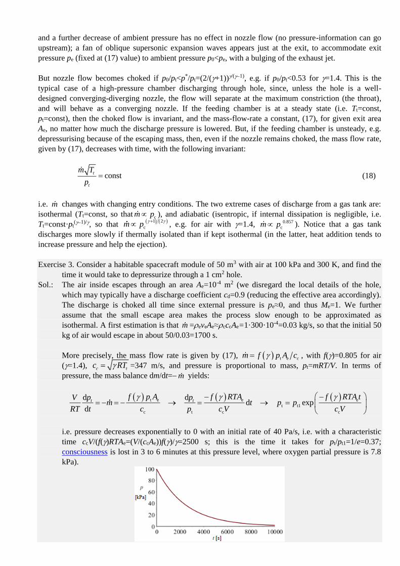
Exercise 3. Consider a habitable spacecraft module of 50 m3 with air at 100 kPa and 300 K, and find the
time it would take to depressurize through a 1 cm2 hole.
Sol.: The air inside escapes through an area Ae=10-4 m2 (we disregard the local details of the hole,
which may typically have a discharge coefficient cd=0.9 (reducing the effective area accordingly).
The discharge is choked all time since external pressure is pe≈0, and thus Me=1. We further
assume that the small escape area makes the process slow enough to be approximated as
isothermal. A first estimation is that m =eveAe≈cccAe=1·300·10-4=0.03 kg/s, so that the initial 50
kg of air would escape in about 50/0.03=1700 s.
More precisely, the mass flow rate is given by (17), t e cm f p A c , with f()=0.805 for air
(=1.4), c tc RT =347 m/s, and pressure is proportional to mass, pt=mRT/V. In terms of
pressure, the mass balance dm/dt=m yields:
t e e e
t t1
c t c c
d dd exp
d
t tf p A f RTA f RTA tp pV
m t p pRT t c p c V c V
i.e. pressure decreases exponentially to 0 with an initial rate of 40 Pa/s, i.e. with a characteristic
time ccV/(f()RTAe=(V/(ccAe))f()/=2500 s; this is the time it takes for pt/pt1=1/e=0.37;
consciousness is lost in 3 to 6 minutes at this pressure level, where oxygen partial pressure is 7.8
kPa).

Fig. E3. Depressurization of a habitable spacecraft module.
If the depressurization were adiabatic, pressure loss would slow down slightly due to the large
temperature drop (e.g., after 2000 s, instead of 45 kPa given by the previous model, pressure
would be 47 kPa, but temperature would had fall to 241 K.
Converging-diverging nozzle
A converging-diverging nozzle ('condi' nozzle, or CD-nozzle) must have a smooth area law, with a
smooth throat, dA/dx=0, for the flow to remain attached to the walls. The flow starts from rest and
accelerates subsonically to a maximum speed at the throat, where it may arrive at M<1 or at M=1, as for
converging nozzles. Again, for the entry conditions we use 'c' (for chamber) or 't' (for total), we use 'e' for
the exit conditions, and '*' for the throat conditions when it is choked (M*=1).
If the flow is subsonic at the throat, it is subsonic all along the nozzle, and exit pressure pe naturally
adapts to environmental pressure p0 because pressure-waves travel upstream faster (at the speed of sound)
than the flow (subsonic), so that pe/p0=1. But now the minimum exit pressure for subsonic flow is no
longer pe=pt(2/(+1))/(1) (pe/p0=0.53 for =1.4), since the choking does not take place at the exit but at
the throat, i.e. it is the throat condition that remains valid, p*=pt(2/(+1))/(1), e.g. p*/p0=0.53 for =1.4;
now the limit for subsonic flow is pe,min,sub>p* because of the pressure recovery in the diverging part.
However, if the flow is isentropic all along the nozzle, be it fully subsonic or supersonic from the throat,
the isentropic equations apply:
1 1
2t t te e
e e e
2
22t e
e e e e e
t
1 2 1 , 1
2 1
11
2
p T pM M
p T p
p Am v A M M
RT
(19)
But if the flow gets sonic at the throat, several downstream conditions may appear. The control parameter
is discharge pressure, p0. Let consider a fix-geometry CD-nozzle, discharging a given gas from a reservoir
with constant conditions (pt,Tt). When lowering the environmental pressure, p0, from the no flow
conditions, p0=pt, we may have the following flow regimes (a plot of pressure variation along the nozzle
is sketched in Fig. 2):
Subsonic throat, implying subsonic flow all along to the exit (evolution a in Fig 2).
Sonic throat (no further increase in mass-flow-rate whatever low the discharge pressure let be).
o Fully subsonic flow except at the throat (evolution b).
o Flow becomes supersonic after the throat, but, before exit, a normal shockwave causes a
sudden transition to subsonic flow (evolution c). It may happen that the flow detaches from
the wall (see the corresponding sketch).
o Flow becomes supersonic after the throat, with the normal shockwave just at the exit
section (evolution d).
o Flow becomes supersonic after the throat, and remains supersonic until de exit, but there,
three cases may be distinguished:
Oblique shock-waves appear at the exit, to compress the exhaust to the higher back
pressure (evolution e). The types of flow with shock-waves (c, d and e in Fig. 2)
are named 'over-expanded' because the supersonic flow in the diverging part of the
nozzle has lowered pressure so much that a recompression is required to match the
discharge pressure. That is the normal situation for a nozzle working at low
new
Highlight
new
Highlight
new
Highlight
altitudes (assuming it is adapted at higher altitudes); it also occurs at short times
after ignition, when chamber pressure is not high enough.
Adapted nozzle, where exit pressure equals discharge pressure (evolution f). Notice
that, as exit pressure pe only depends on chamber conditions for a choked nozzle, a
fix-geometry nozzle can only work adapted at a certain altitude (such that
p0(z)=pe).
Expansion waves appear at the exit, to expand the exhaust to the lower back
pressure (evolution e); this is the normal situation for nozzles working under
vacuum. This type of flow is named 'under-expanded' because exit pressure is not
low-enough, and additional expansion takes place after exhaust.
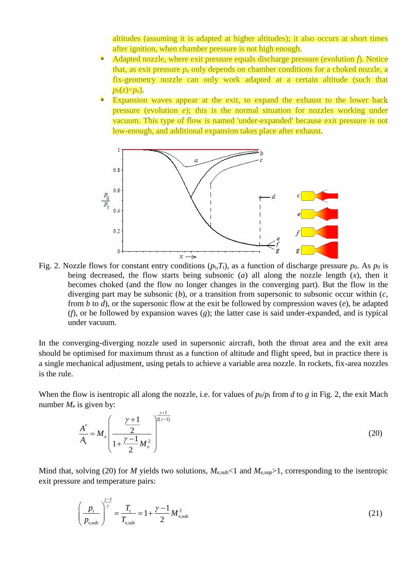
Fig. 2. Nozzle flows for constant entry conditions (pt,Tt), as a function of discharge pressure p0. As p0 is
being decreased, the flow starts being subsonic (a) all along the nozzle length (x), then it
becomes choked (and the flow no longer changes in the converging part). But the flow in the
diverging part may be subsonic (b), or a transition from supersonic to subsonic occur within (c,
from b to d), or the supersonic flow at the exit be followed by compression waves (e), be adapted
(f), or be followed by expansion waves (g); the latter case is said under-expanded, and is typical
under vacuum.
In the converging-diverging nozzle used in supersonic aircraft, both the throat area and the exit area
should be optimised for maximum thrust as a function of altitude and flight speed, but in practice there is
a single mechanical adjustment, using petals to achieve a variable area nozzle. In rockets, fix-area nozzles
is the rule.
When the flow is isentropic all along the nozzle, i.e. for values of p0/pt from d to g in Fig. 2, the exit Mach
number Me is given by:
1
2 1
*
e2ee
1
21
12
AM
AM
(20)
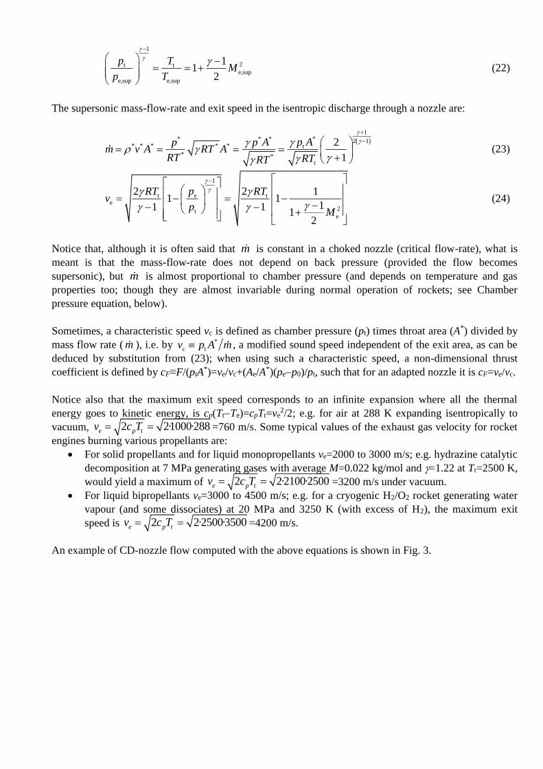
Mind that, solving (20) for M yields two solutions, Me,sub<1 and Me,sup>1, corresponding to the isentropic
exit pressure and temperature pairs:
1
2t te,sub
e,sub e,sub
11
2
p TM
p T
(21)
new
Highlight
1
2t te,sup
e,sup e,sup
11
2
p TM
p T
(22)
The supersonic mass-flow-rate and exit speed in the isentropic discharge through a nozzle are:
1** * * 2 1
* * * * * t
* *t
2
1
p Ap p Am v A RT A
RT RTRT
(23)
1
t e te
2te
2 2 11 1
11 11
2
RT p RTv
pM
(24)
Notice that, although it is often said that m is constant in a choked nozzle (critical flow-rate), what is
meant is that the mass-flow-rate does not depend on back pressure (provided the flow becomes
supersonic), but m is almost proportional to chamber pressure (and depends on temperature and gas
properties too; though they are almost invariable during normal operation of rockets; see Chamber
pressure equation, below).
Sometimes, a characteristic speed vc is defined as chamber pressure (pt) times throat area (A*) divided by
mass flow rate ( m ), i.e. by *
c tv p A m , a modified sound speed independent of the exit area, as can be
deduced by substitution from (23); when using such a characteristic speed, a non-dimensional thrust
coefficient is defined by cF≡F/(ptA*)=ve/vc+(Ae/A
*)(pep0)/pt, such that for an adapted nozzle it is cF=ve/vc.
Notice also that the maximum exit speed corresponds to an infinite expansion where all the thermal
energy goes to kinetic energy, is cp(TtTe)=cpTt=ve2/2; e.g. for air at 288 K expanding isentropically to
vacuum, 2 2·1000·288e p tv c T =760 m/s. Some typical values of the exhaust gas velocity for rocket
engines burning various propellants are:
For solid propellants and for liquid monopropellants ve=2000 to 3000 m/s; e.g. hydrazine catalytic
decomposition at 7 MPa generating gases with average M=0.022 kg/mol and =1.22 at Tt=2500 K,
would yield a maximum of 2 2·2100·2500e p tv c T =3200 m/s under vacuum.
For liquid bipropellants ve=3000 to 4500 m/s; e.g. for a cryogenic H2/O2 rocket generating water
vapour (and some dissociates) at 20 MPa and 3250 K (with excess of H2), the maximum exit
speed is 2 2·2500·3500e p tv c T =4200 m/s.
An example of CD-nozzle flow computed with the above equations is shown in Fig. 3.

Fig. 3. A computed example of choked flow of air (=1.4) in the CD-nozzle geometry shown on top
(nozzle throat at x=1; in scaled arbitrary dimensions, area ratio Ae/A*=2.9). Two isentropic
solutions exist: one totally subsonic (except at the throat, which is sonic), and another that
becomes supersonic after the throat. The plots are: Mach number, local pressure relative to
chamber value, local temperature relative to chamber value, and local speed relative to its throat
value (speed of sound at throat conditions). More detailed nozzle flow simulations can be found
aside.
Looking at the smooth rounding of the nozzle neck (Fig. 3a), it seems amazing the kink in all flow
variables corresponding to the full subsonic solution (the explanation resides in the singularity that (8)-
(11) have for M=1). Another astonishing result is the very rapid pressure changes at the neck: in the
length from x=0.86 to x=1.18 in Fig. 3a, where the nozzle radius varies from r=0.19 to r=0.19 through
r=0.18 at the throat (a 10 % in area change from neck to ends), pressure (scaled with the constant total
pressure) varies from p/pt=0.73 at x=0.86 to p/pt=0.32 at x=1.18 if the flow becomes supersonic (or
recedes to the same subsonic value, p/pt=0.73 at x=1.18 if it remains subsonic), passing by p*/pt=0.53 at
x=1; i.e. between the two sections with radius 5 % larger than the minimum, pressure decreases a 56% (in
supersonic flow; or it recovers, after decreasing a 27%).
It is also impressive how soon the choking occurs when backpressure pe is being decreased: at pe/pt=1
there is no flow, and at pe/pt=0.97 the nozzle is already choked, with a fix mass flow rate whatever the
value of pe/pt<0.97 (if entry conditions are maintained). But, if the flow is choked, how it adapts to the
changing exit pressure? Through discontinuities in the flow, breaking the isentropic condition.

Exercise 4. A liquid bipropellant rocket to be used for the second stage of a space launcher, works at 7
MPa and 3300 K in the combustion chamber, generating gases with a mean molar mass M=0.020
kg/mol, and =1.30, having a nozzle exit diameter of 1.5 m and nozzle expansion ratio of 50. Find:
a) The exit Mach number, assuming fully supersonic flow.
b) Discharge pressure condition for adapted nozzle.
c) Propellants flow rate.
d) Exit speed and thrust at 20 km altitude.
Sol.: a) Given the expansion ratio, ≡Ae/A*, equation (20) yields the exit Mach number:
1
2 1
* 1/501.30
e e e3.8322e ee
11 1.712 0.02 5.1
1 1 0.1512
AM M M
A MM
b) The condition is p0=pe,sup, where the isentropic exit pressure is obtained by (22):
t
e
7 MPa1.30
15.12t
e e,sup
e,sup
11 7.3 kPa
2
p
MpM p
p
i.e. the nozzle would be adapted if the environment is at p0=7.3 kPa (z=18.2 km altitude in ISA
model); if p0<7.3 kPa the flow is under-expanded (fully supersonic and with additional expansion
waves at the exit); however, if p0>7.3 kPa, the flow is over-expanded (and recompressed by shock
waves, either at the exit stage, or within the nozzle).
c) The mass flow rate of propellants equals the mass flow rate of exhaust gases, which is obtained
by (23) either at throat conditions or at the exit stage (it does not depend on p0, provided the
nozzle is choked):
t2
e
1.307 MPa
1.5 48.3 0.02023300 K
25.12t e
e e e e e
t
11 141 kg/s
2
t
p
ARTMp A
m v A M M mRT
d) We have seen in b) that the flow is fully supersonic for p0<7.3 kPa (z>18.2 km altitude in ISA
model), so that the exit velocity is the same as for an adapted nozzle and can be obtained from
(24):
1.301 8.3 0.020
3300 K5.1t e t
e e2te
2 2 11 1 3070 m/s
11 11
2
t
RTMRT p RT
v vp
M
Another way could have been through e e e e e e em v A p v A RT with pe=7.3 kPa,
Ae=·1.52/4=1.77 m2, R=Ru/M=8.3/0.020=415 J/(kg·K), and Te=Tt/(1+(1)Me2/2)=
3300/(1+0.15·5.12)=677 K. The thrust F is:
e e 0 e 141·3070 (7300 5530)·1.77 433 kN +31 kN 464 kNF mv p p A
i.e. F=464 kN (433 kN from jet momentum, and 31 kN from excess pressure relative to the
environment).
Discontinuities in nozzle flow: normal and oblique shocks, expansion fans. Mach diamonds
Consider the isentropic pressure evolution along the nozzle in Fig. 2, . Far downstream of the exit stage,
the exhaust jet (say, more than a couple of exit diameters), the jet , leaving aside a possible adjustment
close to the exit, must be sensibly equal the exit pressure
new
Highlight
new
Highlight
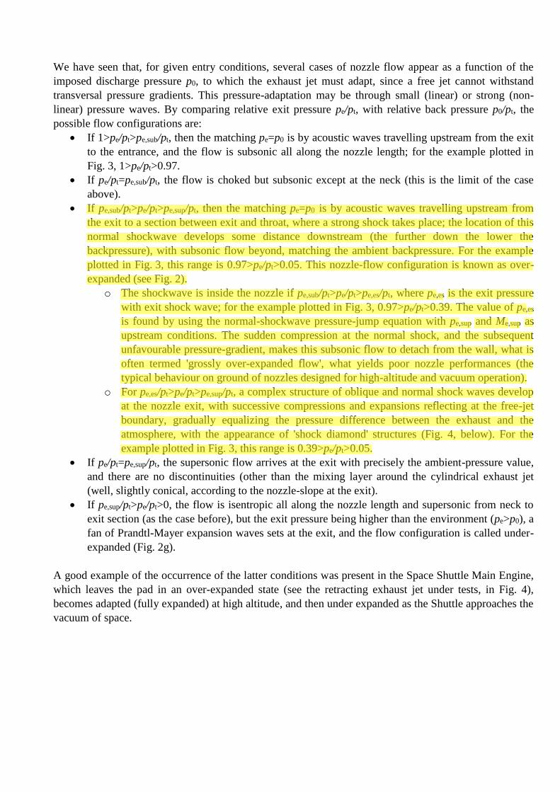
We have seen that, for given entry conditions, several cases of nozzle flow appear as a function of the
imposed discharge pressure p0, to which the exhaust jet must adapt, since a free jet cannot withstand
transversal pressure gradients. This pressure-adaptation may be through small (linear) or strong (non-
linear) pressure waves. By comparing relative exit pressure pe/pt, with relative back pressure p0/pt, the
possible flow configurations are:
If 1>pe/pt>pe,sub/pt, then the matching pe=p0 is by acoustic waves travelling upstream from the exit
to the entrance, and the flow is subsonic all along the nozzle length; for the example plotted in
Fig. 3, 1>pe/pt>0.97.
If pe/pt=pe,sub/pt, the flow is choked but subsonic except at the neck (this is the limit of the case
above).
If pe,sub/pt>pe/pt>pe,sup/pt, then the matching pe=p0 is by acoustic waves travelling upstream from
the exit to a section between exit and throat, where a strong shock takes place; the location of this
normal shockwave develops some distance downstream (the further down the lower the
backpressure), with subsonic flow beyond, matching the ambient backpressure. For the example
plotted in Fig. 3, this range is 0.97>pe/pt>0.05. This nozzle-flow configuration is known as over-
expanded (see Fig. 2).
o The shockwave is inside the nozzle if pe,sub/pt>pe/pt>pe,es/pt, where pe,es is the exit pressure
with exit shock wave; for the example plotted in Fig. 3, 0.97>pe/pt>0.39. The value of pe,es
is found by using the normal-shockwave pressure-jump equation with pe,sup and Me,sup as
upstream conditions. The sudden compression at the normal shock, and the subsequent
unfavourable pressure-gradient, makes this subsonic flow to detach from the wall, what is
often termed 'grossly over-expanded flow', what yields poor nozzle performances (the
typical behaviour on ground of nozzles designed for high-altitude and vacuum operation).
o For pe,es/pt>pe/pt>pe,sup/pt, a complex structure of oblique and normal shock waves develop
at the nozzle exit, with successive compressions and expansions reflecting at the free-jet
boundary, gradually equalizing the pressure difference between the exhaust and the
atmosphere, with the appearance of 'shock diamond' structures (Fig. 4, below). For the
example plotted in Fig. 3, this range is 0.39>pe/pt>0.05.
If pe/pt=pe,sup/pt, the supersonic flow arrives at the exit with precisely the ambient-pressure value,
and there are no discontinuities (other than the mixing layer around the cylindrical exhaust jet
(well, slightly conical, according to the nozzle-slope at the exit).
If pe,sup/pt>pe/pt>0, the flow is isentropic all along the nozzle length and supersonic from neck to
exit section (as the case before), but the exit pressure being higher than the environment (pe>p0), a
fan of Prandtl-Mayer expansion waves sets at the exit, and the flow configuration is called under-
expanded (Fig. 2g).
A good example of the occurrence of the latter conditions was present in the Space Shuttle Main Engine,
which leaves the pad in an over-expanded state (see the retracting exhaust jet under tests, in Fig. 4),
becomes adapted (fully expanded) at high altitude, and then under expanded as the Shuttle approaches the
vacuum of space.
new
Highlight
new
Highlight
new
Highlight

Fig. 4. Shock diamonds (blue cones) in Shuttle's main engine nozzles during STS-120 launch (NASA),
and during tests.
Normal shock within the nozzle
A normal shock generates entropy and thus lowers total pressure (while greatly increasing static
pressure). Mass flow-rate conservation relates both values: total pressure before, pt, and after the shock,
pte (exit total pressure). Applying (15) to throat and exit conditions (at each side of the shock):
1 12 2
* 21 11 1
2 2
t tee e
t t
p pm A M M A
R RT T
(25)
now we get, instead of (14):
1
2 1
*1
2
02
11 12 , with 1
1 21
2
tte e
te e ee
p Ap p M
p A MM
(26)
where we have to solve for Me for given entry and exit pressure (pt, p0), and throat and exit area (A*,Ae).
Once the total pressure loss computed, the actual Mach number just before the shock wave, Ms, is found
from normal-shock relations:
1
1 12
2 2
1 1
2 21 1
12 2
ste
ts s
Mp
pM M
(27)
Solving for this shock-entry Mach number, Ms, allows the spatial location of the front within the nozzle in
terms of areas, from (20). In particular, the shock wave is located precisely at the exit section when the
jump in Mach number across yields a downstream pressure, pe,es (impinging pressure is pe,sup), equal to
the environmental pressure, p0, i.e. when:
new
Highlight

1 2
12 12
2 2 2*20
1
11
1 1 21 , with 12 2
2
t e
Mp A
M M Mp A
M
(28)
where M1 and M2 are the Mach numbers ahead and behind the normal shock wave (M1=Ms). The specific
entropy generation in the normal chock is sgen=s2s1=cpln(T2/T1)Rln(p2/p1)=Rln(pte/pt).
Exercise 5. For air expanding through a nozzle of area ratio Aexit/Athroat=4, find:
a) Mach numbers before and after a shock wave, when the shock gets stabilized inside at a section
with As/Athroat=2.
b) Mach number at the exit section, and ratio of total pressures, in the case above.
c) Discharge pressure to have the normal shock at the exit.
Sol.: a) The Mach number just ahead of the shock is the supersonic solution in (20) with As/A*=2, i.e.
Mahead=2.3. The Mach number just behind the shock is found from the normal-shock equations
(28), i.e. Mbehind=0.55.
b) The exit Mach number is the subsonic solution corresponding to Mbehind=0.55 and area ratio
Aexit/As=2; i.e. Me=0.24. The ratio of total pressures is obtained from (26), pte/pt=0.63.
c) To have the normal shock at the exit, Me-=M1=2.9 from the supersonic solution in (20) with
As/A*=4, and finally M2=Me+=0.48 and p0/pt=0.30 from (28).
Oblique shocks at the nozzle exit
Shock diamonds (or Mach diamonds) are patterns of standing waves that appears in the supersonic
exhaust plume of aerospace propulsion system (turbojet with post-combustor, solid- or liquid-fuel rocket,
ramjet, or scramjet), when operated in an atmosphere with p0>pe (i.e. when the flow is over-expanded in a
CD-nozzle.
When the exhaust flow gets across a normal shock (in red in Fig. 5a) the abrupt compression causes a
sudden temperature increase, with radicals producing non-equilibrium chemiluminescence, which in the
case of LH2/LOX rockets is composed of a weak emission-continuum in the blue and ultraviolet regions
of the spectrum, and a 20 times stronger narrow-band emission at 310 nm, due to excitation of OH and H
radicals and their recombination to H2O. Besides, this sudden heating may cause the ignition of any
residual fuel present in the exhaust, making the Mach disc and trail to glow and become visible like in
Fig. 4. Behind the normal shock, the pressure is greater than that of the ambient atmosphere, so that the
jet expands, trying to equalize with the external air (the expanding waves reflect off the free jet boundary
and towards the centreline), what may require several expansions and compressions.
A similar process occurs in an under-expanded flow exiting from a nozzle at high altitude or under
vacuum (Fig. 5b). The sequence of compression and expansion is identical to that above-described for an
over-expanded nozzle, except that it begins with the creation of an expansion fan rather than oblique
shock waves. This behaviour causes the flow to billow outward initially rather than spindle inward.
a)
new
Highlight

b)
Fig. 5. a) Shock diamonds in an over-expanded flow; the first Mach disc (in red) is separated from the
exit by e 0 e2 3x D p p . b) Wave structures that create shock diamonds in an under-
expanded flow (Aerospaceweb).
Aerospike nozzle
This is a novel design for a fix-geometry nozzle to get adapted at all altitudes. Instead of an outward flow
in a bell-shape wall boundary, in the aerospike nozzle an annular flow issues radially inward along a
decreasing-diameter inner wall (the spike), without external wall (after a cowl lip), see Fig. 6. The outer
ambient pressure regulates the outer plume boundary so that when pe<p0 (over-expansion at low altitudes)
the external pressure squeezes and makes the plume thinner, further accelerating the exhaust instead of
detaching it from the walls. Since ambient pressure controls the nozzle expansion, the flow area at the end
of the aerospike changes with altitude, as if it was a variable-area nozzle, and thus, a very high area ratio
nozzle, which provides high vacuum performance, can also be efficiently operated at sea level. The length
of an ideal spike is about 150 % of a 15° conical nozzle, but performances reduce very little if the spike
length is truncated to the 20 % range, with the formation of a recirculating bubble which, if fed with a
secondary jet at the base, elongates the bubble, forming an aerodynamic contour that resembles the
truncated portion of the spike (this aerodynamic-shape is the reason for the "aerospike" term).
Fig. 6. Different flow configurations in aerospike nozzles, and comparison with bell nozzles.
Back to Propulsion
Related Documents