Novinium Connector / Adapter Evaluation NEETRAC Project Number: 06-009 Final Report August 15, 2006 Requested by: Mr. Glen Bertini Novinium Principal Investigator: T. L. McKoon Reviewed by: Rick Hartlein A Georgia In Research Center of the stitute of Technology

Welcome message from author
This document is posted to help you gain knowledge. Please leave a comment to let me know what you think about it! Share it to your friends and learn new things together.
Transcript

Novinium Connector / Adapter Evaluation
NEETRAC Project Number: 06-009
Final Report August 15, 2006
Requested by: Mr. Glen Bertini Novinium
Principal Investigator:
T. L. McKoon
Reviewed by:
Rick Hartlein
AGeorgia In
Research Center of thestitute of Technology
NEETRAC 06-009 Final Report – August 15, 2006 Page 2 of 76
Novinium Connector / Adapter Evaluation
NEETRAC Project Number: 06-009 Final Report
SUMMARY Novinium requested that NEETRAC evaluate the performance of two sizes of adapter barrels designed to facilitate the injection of underground cables with restoration fluid. The goal of the test program was to establish the current loading and mechanical performance characteristics of various length elbow connectors installed on Novinium adapter barrels installed with a special crimping tool as compared to standard elbow connectors installed with a standard crimping tool. The tests were conducted on cables with 1/0 AWG and 1,000 kcmil aluminum conductor sizes.
The test procedure followed was patterned after the Current Cycle Submersion Test and the Tensile Test outlined in ANSI C119.4, 2004, “American National Standard for Electric Connectors for use Between Aluminum-to-Aluminum or Aluminum-to-Copper Bare Overhead Conductors”. While this standard is for bare conductors, the test protocol is also useful for testing insulated conductors.
The test results show that all connectors met the maximum temperature, temperature stability and resistance stability requirements of the ANSI C119.4 standard. Additionally, all connectors met the minimum tension requirement of the standard.
SAMPLES TESTED Novinium supplied the following:
• 1/0 AWG, Elastimold compression elbow connectors catalog # 02500240
• 1,000 kcmil, Elastimold compression conductor lugs catalog # 03700410
• 1/0 AWG injection adapters Novinium part # 3-2
• 1,000 kcmil injection adapters Novinium part # 12-12
• One 45-ton swaging tool with appropriate dies
• Approximately 225 feet of 1,000 kcmil unfilled strand aluminum conductor with 260 mils of XLPE insulation.
NEETRAC supplied the following:
• Approximately 70 feet of 1/0 AWG, unfilled strand conductor with 175 mils of XLPE insulation.
• Tooling and dies to perform the standard connector installation on both size connectors • All instrumentation and testing equipment to perform the electrical and mechanical tests
NEETRAC 06-009 Final Report – August 15, 2006 Page 3 of 76
INSTALLATION PROCEDURE
Twenty, 1/0 AWG connector samples were installed on the 15 kV class cable with a 1/0 AWG, Class B, unfilled, stranded aluminum conductors. The jacket and metallic shield of the cable was removed, but the insulation and insulation shield remained in place. The connectors were installed using the following procedures:
• Four standard elbow connectors installed with a standard 9/16 die and standard compression tool
• Four standard connectors were cut to accommodate 1.00 inch of conductor. The injection adapter was installed over the elbow connectors with 45-ton swage tool.
• Four standard connectors were cut to accommodate 0.75 inches of conductor. The injection adapter was installed over the elbow connectors with 45-ton swage tool.
• Four standard connectors were cut to accommodate 0.50 inches of conductor. The injection adapter was installed over the elbow connectors with 45-ton swage tool.
• Four standard connectors were cut to accommodate 0.25 inches of conductor. The injection adapter was installed over the elbow connectors with 45-ton swage tool.
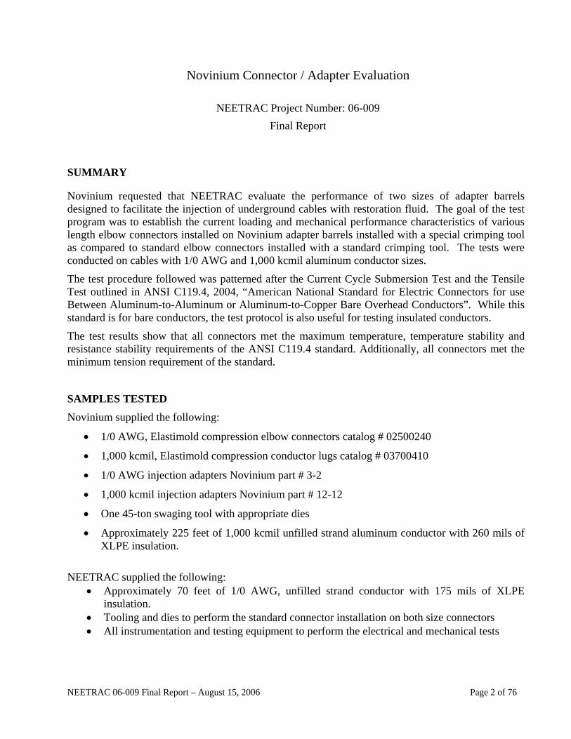
Figure 1 is a photograph of a typical connector cut to length along with swage adapter connector before compression. The connector shown is cut to accommodate 0.50 inches of conductor. Twelve, 1000 kcmil connector samples were installed on the 25 kV class cable with a 1000 kcmil, Class B, unfilled, stranded aluminum conductors. The jacket and metallic shield of the cable were removed, but the insulation and insulation shield remained in place. The connectors were installed using the same procedures as the 1/0 AWG cable. However, the 1000 kcmil adapters required a different compression tool than the 1/0 AWG connectors.
• Four standard compression connectors installed with a standard 1 3/4 hex die with a standard compression tool with 3.5 inches of conductor inserted into the barrel.
• Four standard connectors were cut to accommodate 2.5 inches of conductor. The injection adapter was installed over the compression connectors with 45-ton swage tool.
• Four standard connectors were cut to accommodate 1.5 inches of conductor. The injection adapter was installed over the elbow connectors with 45-ton swage tool.
Figure 4 is a photograph of the completed 1000 kcmil connector adapters.
Connector cut to 0.5 inches
Figure 1: Shortened Connector with Injection Adapter – Before Installation
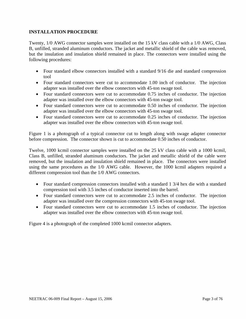
The conductor was inserted into the elbow connector. The adapter barrel was installed over the elbow connector and the first swage was made on the aluminum portion of the elbow. The last swage was made over the portion of the adapter located over the insulation. Figure 2 is a photograph of an injection adapter swaged to the elbow connector. Figure 3 shows the injection adapter with all swages completed.
First Compression Made Here
Figure 2: Injection Adapter Swaged on Elbow Connector
NEETRAC 06-009 Final Report – August 15, 2006 Page 4 of 76

Figure 3: Completed Installation – 1/0 AWG Connector/Adapters
Figure 4: Completed Installation - 1000 kcmil Connector/Adapters
NEETRAC 06-009 Final Report – August 15, 2006 Page 5 of 76

CURRENT CYCLE TESTS The ANSI C119.4, 2004 100 Cycle Current Cycle Submersion Test was used to evaluate all conductor / connector combinations. The performance criteria included maximum temperature, temperature stability and resistance stability. The maximum temperature measurements were used to determine the temperature of the connector relative to the temperature of the control conductor. This evaluation was performed at the end of each current loading cycle. The temperature and resistance stability criteria establish the stability of the connectors over the 100 cycle test period.
Heat Cycle Tests
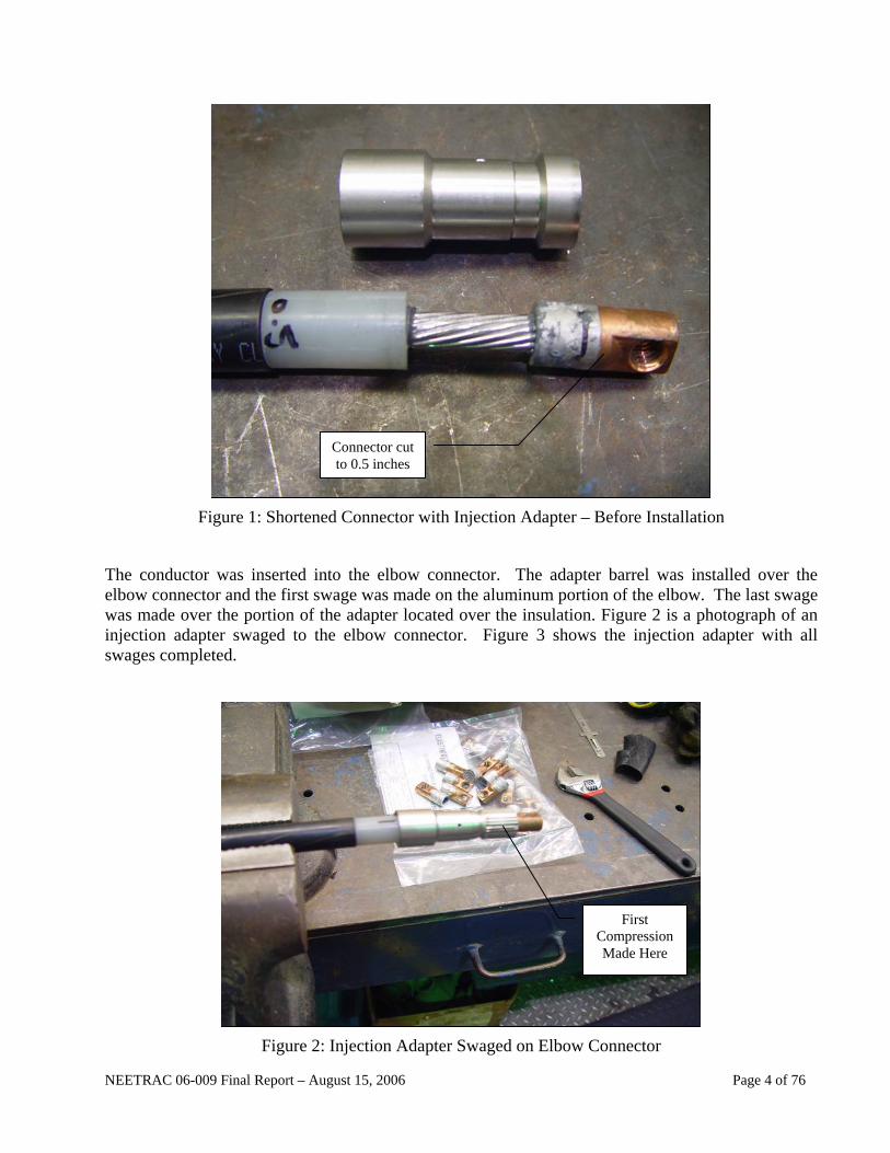
The connectors and conductors were assembled in a series loop with equalizers. The equalizers are used to provide an equipotential contact point for resistance measurements. All connector testing was performed on insulated conductors. However, the insulation was removed from the control conductors. Thermocouples were installed at the first swage in each connector. The control conductor was monitored with one thermocouple in the center portion of the conductor. The 1/0 AWG control required a 24 inch length. The 1000 kcmil required a 72 inch control conductor. Figure 5 is a photograph of a typical connector with thermocouple installed. Figure 6 shows the test loop installed over the current cycle submersion test tank typical for both loops.
Figure 5: Typical Thermocouple Location (1000 kcmil Connector Shown)
NEETRAC 06-009 Final Report – August 15, 2006 Page 6 of 76
Figure 6: 1000 kcmil Test Loop Installed over Current Cycle Submersion Tank
Sufficient current was applied to each loop to achieve a control conductor temperature of 100 degrees Celsius above ambient temperature. The 1/0 AWG loop consisted of a 60 minute “current on” period followed by a 30 minute “current off” period. The 1000 kcmil loop required a 120 minute “current on” followed by a 30 minute “current off” period. At the end of the current on period, the connectors and control conductor were submerged in water chilled to approximately 4 °C.
It should be noted that the 1/0 AWG test loop was first tested in a test cell that was recently “upgraded” with new temperature and resistance monitoring equipment. After this 100 cycle test was complete, the resistance data was found to be erratic and was ultimately determined to be inaccurate. With the permission of Novinium, the 100 cycle test was repeated in a test cell with measuring equipment that was known to be accurate. The data in this report is from the second test performed on the 1/0 AWG connectors.
Mechanical Tests
Three connectors of each assembly combination were tested to Section 7.3, Pullout Test of ANSI C119.4. The connectors tested are Class 3 connectors and are required to hold 5% of the conductor’s rating. The samples were pulled using the NEETRAC 150,000 MTS tensile machine. The connector end of each test sample was connected to the machine using appropriate hardware. The opposite end was held using a wire “basket” grip.
NEETRAC 06-009 Final Report – August 15, 2006 Page 7 of 76
NEETRAC 06-009 Final Report – August 15, 2006 Page 8 of 76
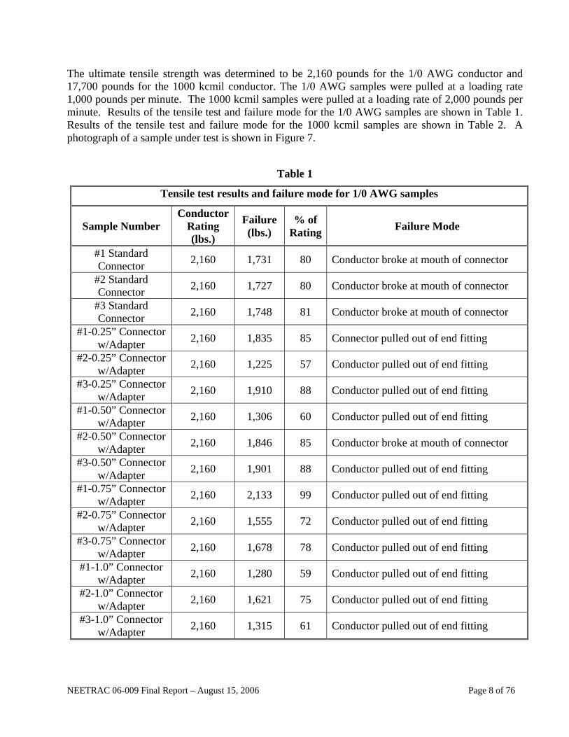
The ultimate tensile strength was determined to be 2,160 pounds for the 1/0 AWG conductor and 17,700 pounds for the 1000 kcmil conductor. The 1/0 AWG samples were pulled at a loading rate 1,000 pounds per minute. The 1000 kcmil samples were pulled at a loading rate of 2,000 pounds per minute. Results of the tensile test and failure mode for the 1/0 AWG samples are shown in Table 1. Results of the tensile test and failure mode for the 1000 kcmil samples are shown in Table 2. A photograph of a sample under test is shown in Figure 7.
Table 1
Tensile test results and failure mode for 1/0 AWG samples
Sample Number Conductor
Rating (lbs.)
Failure (lbs.)
% of Rating Failure Mode
#1 Standard Connector 2,160 1,731 80 Conductor broke at mouth of connector
#2 Standard Connector 2,160 1,727 80 Conductor broke at mouth of connector
#3 Standard Connector 2,160 1,748 81 Conductor broke at mouth of connector
#1-0.25” Connector w/Adapter 2,160 1,835 85 Connector pulled out of end fitting
#2-0.25” Connector w/Adapter 2,160 1,225 57 Conductor pulled out of end fitting
#3-0.25” Connector w/Adapter 2,160 1,910 88 Conductor pulled out of end fitting
#1-0.50” Connector w/Adapter 2,160 1,306 60 Conductor pulled out of end fitting
#2-0.50” Connector w/Adapter 2,160 1,846 85 Conductor broke at mouth of connector
#3-0.50” Connector w/Adapter 2,160 1,901 88 Conductor pulled out of end fitting
#1-0.75” Connector w/Adapter 2,160 2,133 99 Conductor pulled out of end fitting
#2-0.75” Connector w/Adapter 2,160 1,555 72 Conductor pulled out of end fitting
#3-0.75” Connector w/Adapter 2,160 1,678 78 Conductor pulled out of end fitting
#1-1.0” Connector w/Adapter 2,160 1,280 59 Conductor pulled out of end fitting
#2-1.0” Connector w/Adapter 2,160 1,621 75 Conductor pulled out of end fitting
#3-1.0” Connector w/Adapter 2,160 1,315 61 Conductor pulled out of end fitting

TABLE 2
Tensile test results and failure mode for 1000 kcmil samples
Sample Number Conductor
Rating lbs.
Failure
Lbs. % of
Rating Failure Mode
#1 Standard Connector 17,700 3,140 18 Connector eye pulled through
#2 Standard Connector 17,700 3,140 18 Connector eye pulled through
#3 Standard Connector 17,700 3,160 18 Connector eye pulled through
#1-1.5” Connector w/Adapter 17,700 3,120 18 Connector eye pulled through
#2-1.5” Connector w/Adapter 17,700 3,160 18 Connector eye pulled through
#3-1.5” Connector w/Adapter 17,700 3,210 18 Connector eye pulled through
#1-2.5” Connector w/Adapter 17,700 3,260 18 Connector eye pulled through
#2-2.5” Connector w/Adapter 17,700 3,250 18 Connector eye pulled through
#3-2.5” Connector w/Adapter 17,700 3,200 18 Connector eye pulled through
Figure 7: Tensile Test Setup - 1000 kcmil Cable with Connector/Adapter
NEETRAC 06-009 Final Report – August 15, 2006 Page 9 of 76
NEETRAC 06-009 Final Report – August 15, 2006 Page 10 of 76
CONCLUSIONS All connectors tested in this project met the thermal, electrical and mechanical acceptance criteria of ANSI C119.4, 2004. It should be noted that the 1/0 AWG met the thermal and electrical performance criteria after being subjected to two current cycle submersion tests. Graphs detailing the thermal and electrical performance of each connector are included in the Appendix.
REFERENCES
ANSI C119.4, 2004 American National Standard for Electric Connectors, Connectors for Use Between Aluminum-to-Aluminum or Aluminum-to-Copper Bare Overhead Conductors
EQUIPMENT USED
• HP 3421A Data Acquisition System, Control Numbers CQ 0226 and CQ 0218 (temperature data)
• AVO Ducter DLR0, Control Number CQ 1083 (resistance data)
• Current Cycle Submersion Test Fixture and AC Current Loading Power Supply
• MTS Control Number CQ 0195

NEETRAC 06-009 Final Report – August 15, 2006 Page 11 of 76
APPENDIX
GRAPHS FOR 1/0 AWG CONNECTORS
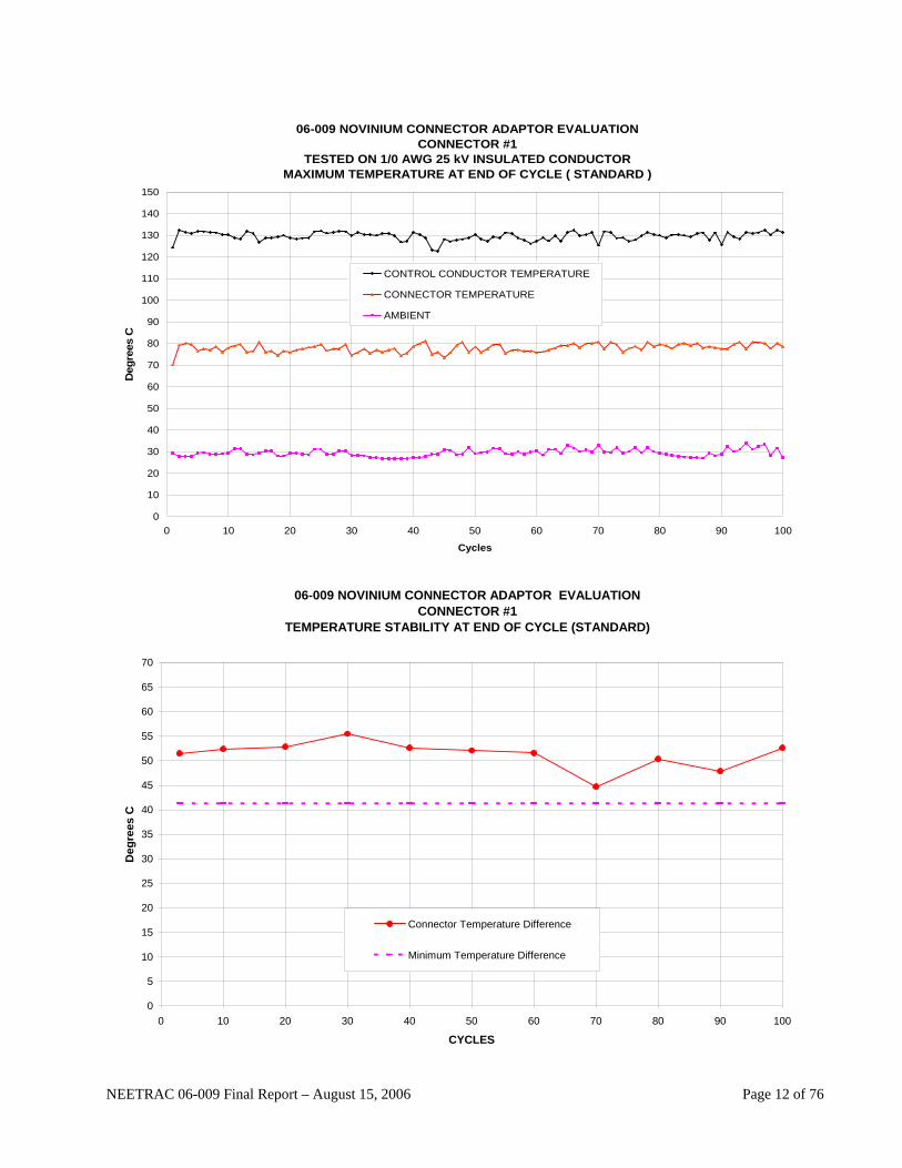
06-009 NOVINIUM CONNECTOR ADAPTOR EVALUATIONCONNECTOR #1
TESTED ON 1/0 AWG 25 kV INSULATED CONDUCTORMAXIMUM TEMPERATURE AT END OF CYCLE ( STANDARD )
0
10
20
30
40
50
60
70
80
90
100
110
120
130
140
150
0 10 20 30 40 50 60 70 80 90 100
Cycles
Deg
rees
C
CONTROL CONDUCTOR TEMPERATURE
CONNECTOR TEMPERATURE
AMBIENT
06-009 NOVINIUM CONNECTOR ADAPTOR EVALUATION
CONNECTOR #1 TEMPERATURE STABILITY AT END OF CYCLE (STANDARD)
0
5
10
15
20
25
30
35
40
45
50
55
60
65
70
0 10 20 30 40 50 60 70 80 90 100
CYCLES
Deg
rees
C
Connector Temperature Difference
Minimum Temperature Difference
NEETRAC 06-009 Final Report – August 15, 2006 Page 12 of 76
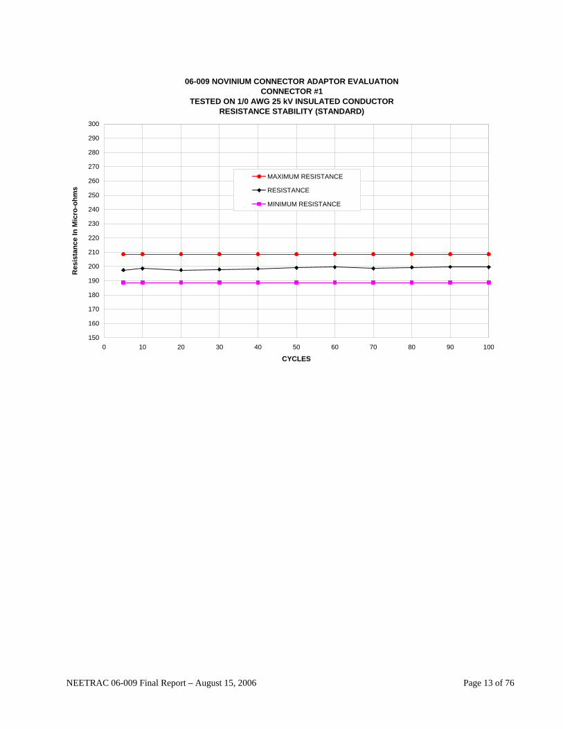
06-009 NOVINIUM CONNECTOR ADAPTOR EVALUATIONCONNECTOR #1
TESTED ON 1/0 AWG 25 kV INSULATED CONDUCTORRESISTANCE STABILITY (STANDARD)
150
160
170
180
190
200
210
220
230
240
250
260
270
280
290
300
0 10 20 30 40 50 60 70 80 90 100
CYCLES
Res
ista
nce
In M
icro
-ohm
s
MAXIMUM RESISTANCE
RESISTANCE
MINIMUM RESISTANCE
NEETRAC 06-009 Final Report – August 15, 2006 Page 13 of 76
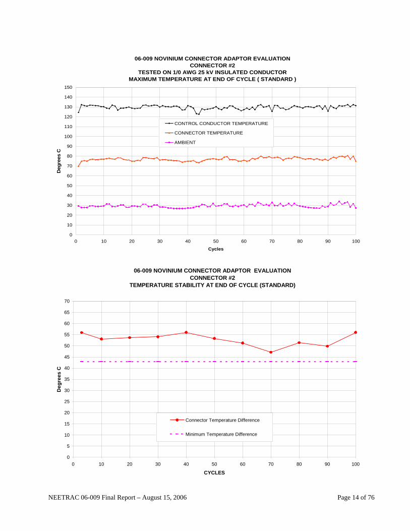
06-009 NOVINIUM CONNECTOR ADAPTOR EVALUATIONCONNECTOR #2
TESTED ON 1/0 AWG 25 kV INSULATED CONDUCTORMAXIMUM TEMPERATURE AT END OF CYCLE ( STANDARD )
0
10
20
30
40
50
60
70
80
90
100
110
120
130
140
150
0 10 20 30 40 50 60 70 80 90 100
Cycles
Deg
rees
C
CONTROL CONDUCTOR TEMPERATURE
CONNECTOR TEMPERATURE
AMBIENT
06-009 NOVINIUM CONNECTOR ADAPTOR EVALUATION
CONNECTOR #2 TEMPERATURE STABILITY AT END OF CYCLE (STANDARD)
0
5
10
15
20
25
30
35
40
45
50
55
60
65
70
0 10 20 30 40 50 60 70 80 90 100
CYCLES
Deg
rees
C
Connector Temperature Difference
Minimum Temperature Difference
NEETRAC 06-009 Final Report – August 15, 2006 Page 14 of 76

06-009 NOVINIUM CONNECTOR ADAPTOR EVALUATIONCONNECTOR #2
TESTED ON 1/0 AWG 25 kV INSULATED CONDUCTORRESISTANCE STABILITY (STANDARD)
150
160
170
180
190
200
210
220
230
240
250
260
270
280
290
300
0 10 20 30 40 50 60 70 80 90 100
CYCLES
Res
ista
nce
In M
icro
-ohm
s
MAXIMUM RESISTANCE
RESISTANCE
MINIMUM RESISTANCE
NEETRAC 06-009 Final Report – August 15, 2006 Page 15 of 76

06-009 NOVINIUM CONNECTOR ADAPTOR EVALUATIONCONNECTOR #3
TESTED ON 1/0 AWG 25 kV INSULATED CONDUCTORMAXIMUM TEMPERATURE AT END OF CYCLE ( STANDARD )
0
10
20
30
40
50
60
70
80
90
100
110
120
130
140
150
0 10 20 30 40 50 60 70 80 90 100
Cycles
Deg
rees
C
CONTROL CONDUCTOR TEMPERATURE
CONNECTOR TEMPERATURE
AMBIENT
06-009 NOVINIUM CONNECTOR ADAPTOR EVALUATION
CONNECTOR #3 TEMPERATURE STABILITY AT END OF CYCLE (STANDARD)
0
5
10
15
20
25
30
35
40
45
50
55
60
65
70
0 10 20 30 40 50 60 70 80 90 100
CYCLES
Deg
rees
C
Connector Temperature Difference
Minimum Temperature Difference
NEETRAC 06-009 Final Report – August 15, 2006 Page 16 of 76

06-009 NOVINIUM CONNECTOR ADAPTOR EVALUATIONCONNECTOR #3
TESTED ON 1/0 AWG 25 kV INSULATED CONDUCTORRESISTANCE STABILITY (STANDARD)
150
160
170
180
190
200
210
220
230
240
250
260
270
280
290
300
0 10 20 30 40 50 60 70 80 90 100
CYCLES
Res
ista
nce
In M
icro
-ohm
s MAXIMUM RESISTANCE
RESISTANCE
MINIMUM RESISTANCE
NEETRAC 06-009 Final Report – August 15, 2006 Page 17 of 76
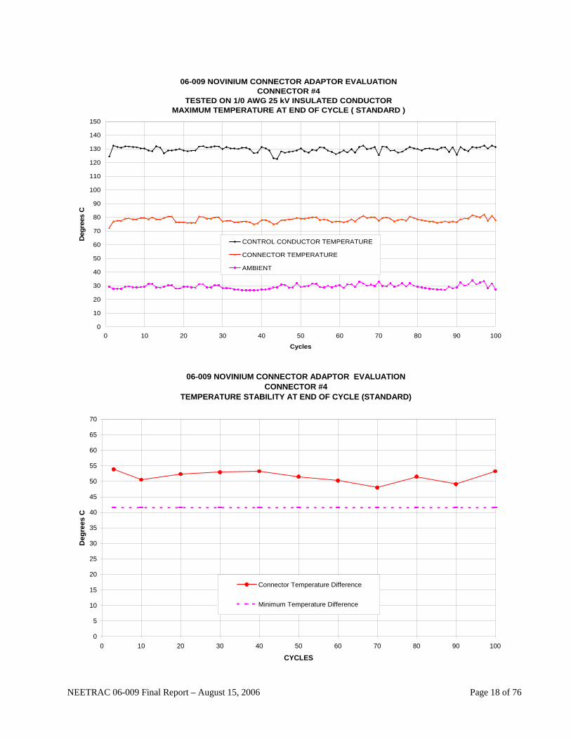
06-009 NOVINIUM CONNECTOR ADAPTOR EVALUATIONCONNECTOR #4
TESTED ON 1/0 AWG 25 kV INSULATED CONDUCTORMAXIMUM TEMPERATURE AT END OF CYCLE ( STANDARD )
0
10
20
30
40
50
60
70
80
90
100
110
120
130
140
150
0 10 20 30 40 50 60 70 80 90 100
Cycles
Deg
rees
C
CONTROL CONDUCTOR TEMPERATURE
CONNECTOR TEMPERATURE
AMBIENT
06-009 NOVINIUM CONNECTOR ADAPTOR EVALUATION
CONNECTOR #4 TEMPERATURE STABILITY AT END OF CYCLE (STANDARD)
0
5
10
15
20
25
30
35
40
45
50
55
60
65
70
0 10 20 30 40 50 60 70 80 90 100
CYCLES
Deg
rees
C
Connector Temperature Difference
Minimum Temperature Difference
NEETRAC 06-009 Final Report – August 15, 2006 Page 18 of 76

06-009 NOVINIUM CONNECTOR ADAPTOR EVALUATIONCONNECTOR #4
TESTED ON 1/0 AWG 25 kV INSULATED CONDUCTORRESISTANCE STABILITY (STANDARD)
150
160
170
180
190
200
210
220
230
240
250
260
270
280
290
300
0 10 20 30 40 50 60 70 80 90 100
CYCLES
Res
ista
nce
In M
icro
-ohm
s
MAXIMUM RESISTANCE
RESISTANCE
MINIMUM RESISTANCE
NEETRAC 06-009 Final Report – August 15, 2006 Page 19 of 76
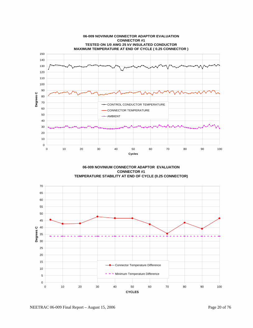
06-009 NOVINIUM CONNECTOR ADAPTOR EVALUATIONCONNECTOR #1
TESTED ON 1/0 AWG 25 kV INSULATED CONDUCTORMAXIMUM TEMPERATURE AT END OF CYCLE ( 0.25 CONNECTOR )
0
10
20
30
40
50
60
70
80
90
100
110
120
130
140
150
0 10 20 30 40 50 60 70 80 90 100
Cycles
Deg
rees
C
CONTROL CONDUCTOR TEMPERATURE
CONNECTOR TEMPERATURE
AMBIENT
06-009 NOVINIUM CONNECTOR ADAPTOR EVALUATION
CONNECTOR #1 TEMPERATURE STABILITY AT END OF CYCLE (0.25 CONNECTOR)
0
5
10
15
20
25
30
35
40
45
50
55
60
65
70
0 10 20 30 40 50 60 70 80 90 100
CYCLES
Deg
rees
C
Connector Temperature Difference
Minimum Temperature Difference
NEETRAC 06-009 Final Report – August 15, 2006 Page 20 of 76

06-009 NOVINIUM CONNECTOR ADAPTOR EVALUATIONCONNECTOR #1
TESTED ON 1/0 AWG 25 kV INSULATED CONDUCTORRESISTANCE STABILITY (0.25 CONNECTOR)
150
160
170
180
190
200
210
220
230
240
250
260
270
280
290
300
0 10 20 30 40 50 60 70 80 90 100
CYCLES
Res
ista
nce
In M
icro
-ohm
s
MAXIMUM RESISTANCE
RESISTANCE
MINIMUM RESISTANCE
NEETRAC 06-009 Final Report – August 15, 2006 Page 21 of 76

06-009 NOVINIUM CONNECTOR ADAPTOR EVALUATIONCONNECTOR #2
TESTED ON 1/0 AWG 25 kV INSULATED CONDUCTORMAXIMUM TEMPERATURE AT END OF CYCLE ( 0.25 CONNECTOR )
0
10
20
30
40
50
60
70
80
90
100
110
120
130
140
150
0 10 20 30 40 50 60 70 80 90 100
Cycles
Deg
rees
C
CONTROL CONDUCTOR TEMPERATURE
CONNECTOR TEMPERATURE
AMBIENT
06-009 NOVINIUM CONNECTOR ADAPTOR EVALUATION
CONNECTOR #2 TEMPERATURE STABILITY AT END OF CYCLE (0.25 CONNECTOR)
0
5
10
15
20
25
30
35
40
45
50
55
60
65
70
0 10 20 30 40 50 60 70 80 90 100
CYCLES
Deg
rees
C
Connector Temperature Difference
Minimum Temperature Difference
NEETRAC 06-009 Final Report – August 15, 2006 Page 22 of 76
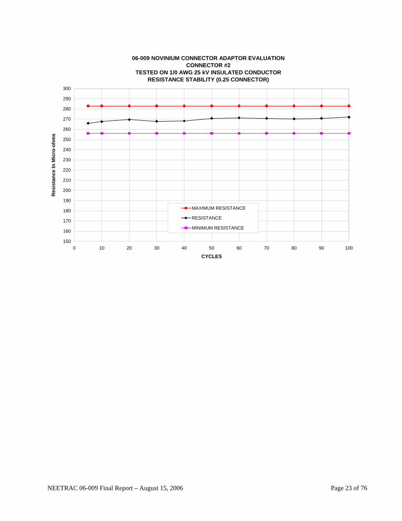
06-009 NOVINIUM CONNECTOR ADAPTOR EVALUATIONCONNECTOR #2
TESTED ON 1/0 AWG 25 kV INSULATED CONDUCTORRESISTANCE STABILITY (0.25 CONNECTOR)
150
160
170
180
190
200
210
220
230
240
250
260
270
280
290
300
0 10 20 30 40 50 60 70 80 90 100
CYCLES
Res
ista
nce
In M
icro
-ohm
s
MAXIMUM RESISTANCE
RESISTANCE
MINIMUM RESISTANCE
NEETRAC 06-009 Final Report – August 15, 2006 Page 23 of 76
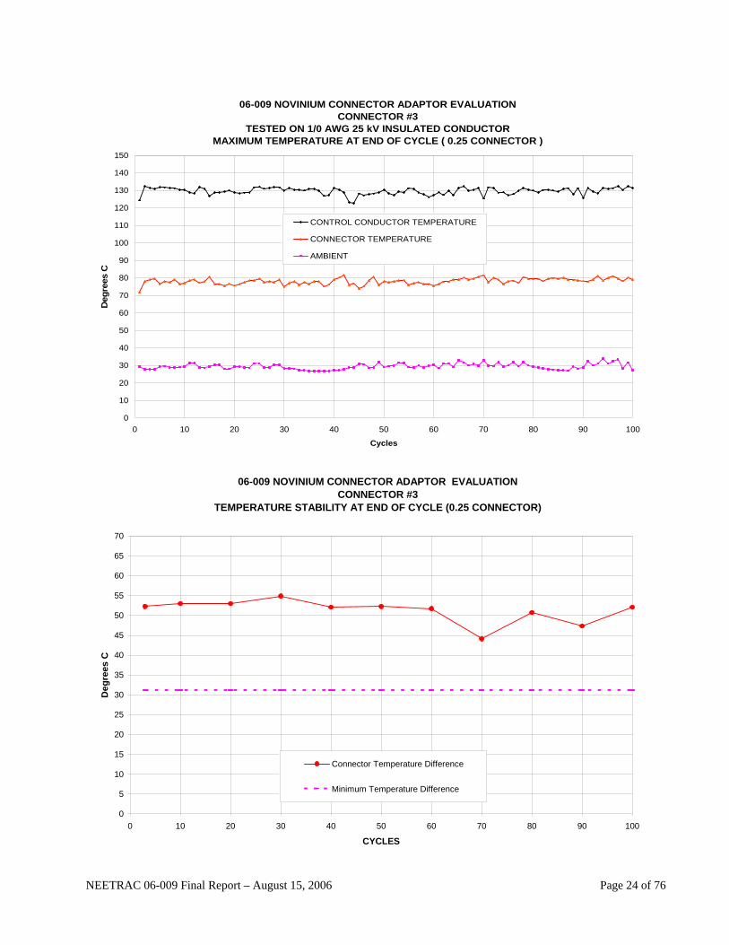
06-009 NOVINIUM CONNECTOR ADAPTOR EVALUATIONCONNECTOR #3
TESTED ON 1/0 AWG 25 kV INSULATED CONDUCTORMAXIMUM TEMPERATURE AT END OF CYCLE ( 0.25 CONNECTOR )
0
10
20
30
40
50
60
70
80
90
100
110
120
130
140
150
0 10 20 30 40 50 60 70 80 90 100
Cycles
Deg
rees
C
CONTROL CONDUCTOR TEMPERATURE
CONNECTOR TEMPERATURE
AMBIENT
06-009 NOVINIUM CONNECTOR ADAPTOR EVALUATION
CONNECTOR #3 TEMPERATURE STABILITY AT END OF CYCLE (0.25 CONNECTOR)
0
5
10
15
20
25
30
35
40
45
50
55
60
65
70
0 10 20 30 40 50 60 70 80 90 100
CYCLES
Deg
rees
C
Connector Temperature Difference
Minimum Temperature Difference
NEETRAC 06-009 Final Report – August 15, 2006 Page 24 of 76

06-009 NOVINIUM CONNECTOR ADAPTOR EVALUATIONCONNECTOR #3
TESTED ON 1/0 AWG 25 kV INSULATED CONDUCTORRESISTANCE STABILITY (0.25 CONNECTOR)
150
160
170
180
190
200
210
220
230
240
250
260
270
280
290
300
0 10 20 30 40 50 60 70 80 90 100
CYCLES
Res
ista
nce
In M
icro
-ohm
s
MAXIMUM RESISTANCE
RESISTANCE
MINIMUM RESISTANCE
NEETRAC 06-009 Final Report – August 15, 2006 Page 25 of 76
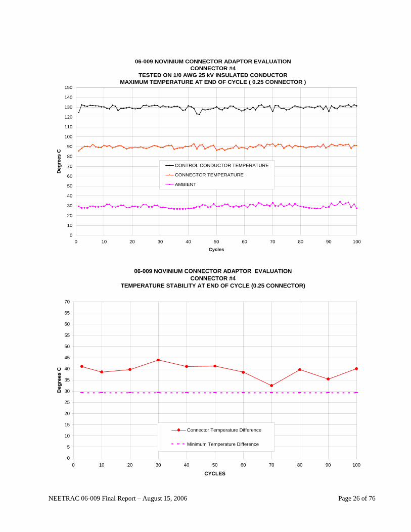
06-009 NOVINIUM CONNECTOR ADAPTOR EVALUATIONCONNECTOR #4
TESTED ON 1/0 AWG 25 kV INSULATED CONDUCTORMAXIMUM TEMPERATURE AT END OF CYCLE ( 0.25 CONNECTOR )
0
10
20
30
40
50
60
70
80
90
100
110
120
130
140
150
0 10 20 30 40 50 60 70 80 90 100
Cycles
Deg
rees
C
CONTROL CONDUCTOR TEMPERATURE
CONNECTOR TEMPERATURE
AMBIENT
06-009 NOVINIUM CONNECTOR ADAPTOR EVALUATION
CONNECTOR #4 TEMPERATURE STABILITY AT END OF CYCLE (0.25 CONNECTOR)
0
5
10
15
20
25
30
35
40
45
50
55
60
65
70
0 10 20 30 40 50 60 70 80 90 100
CYCLES
Deg
rees
C
Connector Temperature Difference
Minimum Temperature Difference
NEETRAC 06-009 Final Report – August 15, 2006 Page 26 of 76

06-009 NOVINIUM CONNECTOR ADAPTOR EVALUATIONCONNECTOR #4
TESTED ON 1/0 AWG 25 kV INSULATED CONDUCTORRESISTANCE STABILITY (0.25 CONNECTOR)
150
160
170
180
190
200
210
220
230
240
250
260
270
280
290
300
0 10 20 30 40 50 60 70 80 90 100
CYCLES
Res
ista
nce
In M
icro
-ohm
s
MAXIMUM RESISTANCE
RESISTANCE
MINIMUM RESISTANCE
NEETRAC 06-009 Final Report – August 15, 2006 Page 27 of 76

06-009 NOVINIUM CONNECTOR ADAPTOR EVALUATIONCONNECTOR #1
TESTED ON 1/0 AWG 25 kV INSULATED CONDUCTORMAXIMUM TEMPERATURE AT END OF CYCLE ( 0.50 CONNECTOR )
0
10
20
30
40
50
60
70
80
90
100
110
120
130
140
150
0 10 20 30 40 50 60 70 80 90 100
Cycles
Deg
rees
C
CONTROL CONDUCTOR TEMPERATURE
CONNECTOR TEMPERATURE
AMBIENT
06-009 NOVINIUM CONNECTOR ADAPTOR EVALUATION
CONNECTOR #1 TEMPERATURE STABILITY AT END OF CYCLE (0.50 CONNECTOR)
0
5
10
15
20
25
30
35
40
45
50
55
60
65
70
0 10 20 30 40 50 60 70 80 90 100
CYCLES
Deg
rees
C
Connector Temperature Difference
Minimum Temperature Difference
NEETRAC 06-009 Final Report – August 15, 2006 Page 28 of 76

06-009 NOVINIUM CONNECTOR ADAPTOR EVALUATIONCONNECTOR #1
TESTED ON 1/0 AWG 25 kV INSULATED CONDUCTORRESISTANCE STABILITY (0.50 CONNECTOR)
150
160
170
180
190
200
210
220
230
240
250
260
270
280
290
300
0 10 20 30 40 50 60 70 80 90 100
CYCLES
Res
ista
nce
In M
icro
-ohm
s
MAXIMUM RESISTANCE
RESISTANCE
MINIMUM RESISTANCE
NEETRAC 06-009 Final Report – August 15, 2006 Page 29 of 76
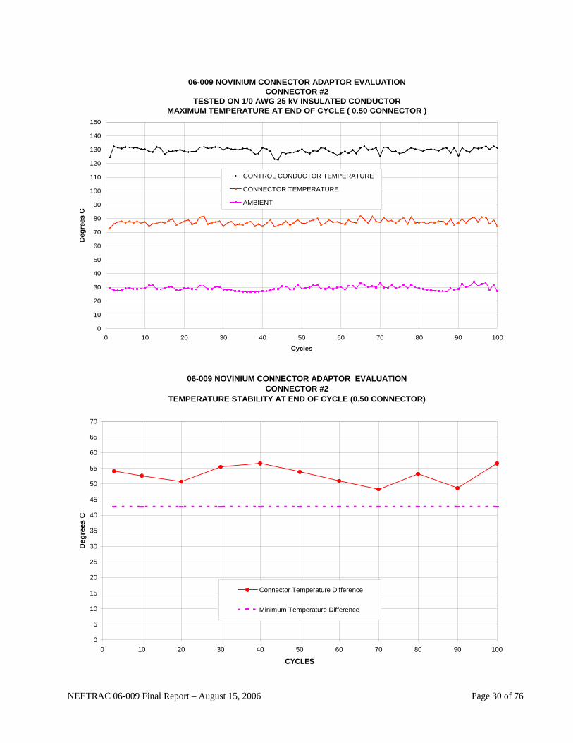
06-009 NOVINIUM CONNECTOR ADAPTOR EVALUATIONCONNECTOR #2
TESTED ON 1/0 AWG 25 kV INSULATED CONDUCTORMAXIMUM TEMPERATURE AT END OF CYCLE ( 0.50 CONNECTOR )
0
10
20
30
40
50
60
70
80
90
100
110
120
130
140
150
0 10 20 30 40 50 60 70 80 90 100
Cycles
Deg
rees
C
CONTROL CONDUCTOR TEMPERATURE
CONNECTOR TEMPERATURE
AMBIENT
06-009 NOVINIUM CONNECTOR ADAPTOR EVALUATION
CONNECTOR #2 TEMPERATURE STABILITY AT END OF CYCLE (0.50 CONNECTOR)
0
5
10
15
20
25
30
35
40
45
50
55
60
65
70
0 10 20 30 40 50 60 70 80 90 100
CYCLES
Deg
rees
C
Connector Temperature Difference
Minimum Temperature Difference
NEETRAC 06-009 Final Report – August 15, 2006 Page 30 of 76

06-009 NOVINIUM CONNECTOR ADAPTOR EVALUATIONCONNECTOR #2
TESTED ON 1/0 AWG 25 kV INSULATED CONDUCTORRESISTANCE STABILITY (0.50 CONNECTOR)
150
160
170
180
190
200
210
220
230
240
250
260
270
280
290
300
0 10 20 30 40 50 60 70 80 90 100
CYCLES
Res
ista
nce
In M
icro
-ohm
s
MAXIMUM RESISTANCE
RESISTANCE
MINIMUM RESISTANCE
NEETRAC 06-009 Final Report – August 15, 2006 Page 31 of 76
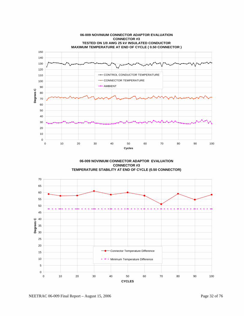
06-009 NOVINIUM CONNECTOR ADAPTOR EVALUATIONCONNECTOR #3
TESTED ON 1/0 AWG 25 kV INSULATED CONDUCTORMAXIMUM TEMPERATURE AT END OF CYCLE ( 0.50 CONNECTOR )
0
10
20
30
40
50
60
70
80
90
100
110
120
130
140
150
0 10 20 30 40 50 60 70 80 90 100
Cycles
Deg
rees
C
CONTROL CONDUCTOR TEMPERATURE
CONNECTOR TEMPERATURE
AMBIENT
06-009 NOVINIUM CONNECTOR ADAPTOR EVALUATION
CONNECTOR #3 TEMPERATURE STABILITY AT END OF CYCLE (0.50 CONNECTOR)
0
5
10
15
20
25
30
35
40
45
50
55
60
65
70
0 10 20 30 40 50 60 70 80 90 100
CYCLES
Deg
rees
C
Connector Temperature Difference
Minimum Temperature Difference
NEETRAC 06-009 Final Report – August 15, 2006 Page 32 of 76
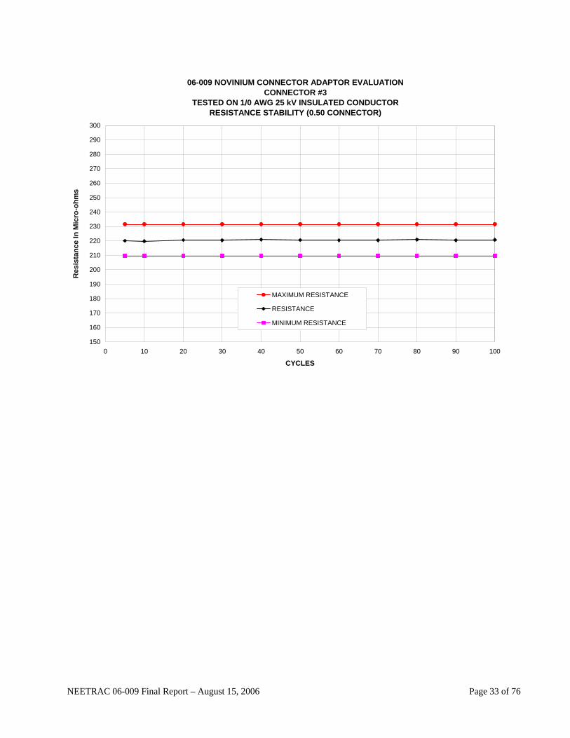
06-009 NOVINIUM CONNECTOR ADAPTOR EVALUATIONCONNECTOR #3
TESTED ON 1/0 AWG 25 kV INSULATED CONDUCTORRESISTANCE STABILITY (0.50 CONNECTOR)
150
160
170
180
190
200
210
220
230
240
250
260
270
280
290
300
0 10 20 30 40 50 60 70 80 90 100
CYCLES
Res
ista
nce
In M
icro
-ohm
s
MAXIMUM RESISTANCE
RESISTANCE
MINIMUM RESISTANCE
NEETRAC 06-009 Final Report – August 15, 2006 Page 33 of 76
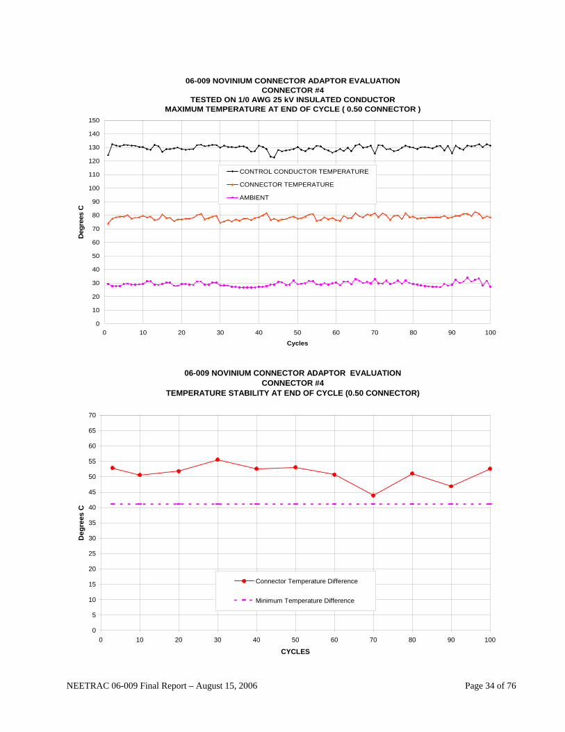
06-009 NOVINIUM CONNECTOR ADAPTOR EVALUATIONCONNECTOR #4
TESTED ON 1/0 AWG 25 kV INSULATED CONDUCTORMAXIMUM TEMPERATURE AT END OF CYCLE ( 0.50 CONNECTOR )
0
10
20
30
40
50
60
70
80
90
100
110
120
130
140
150
0 10 20 30 40 50 60 70 80 90 100
Cycles
Deg
rees
C
CONTROL CONDUCTOR TEMPERATURE
CONNECTOR TEMPERATURE
AMBIENT
06-009 NOVINIUM CONNECTOR ADAPTOR EVALUATION
CONNECTOR #4 TEMPERATURE STABILITY AT END OF CYCLE (0.50 CONNECTOR)
0
5
10
15
20
25
30
35
40
45
50
55
60
65
70
0 10 20 30 40 50 60 70 80 90 100
CYCLES
Deg
rees
C
Connector Temperature Difference
Minimum Temperature Difference
NEETRAC 06-009 Final Report – August 15, 2006 Page 34 of 76

06-009 NOVINIUM CONNECTOR ADAPTOR EVALUATIONCONNECTOR #4
TESTED ON 1/0 AWG 25 kV INSULATED CONDUCTORRESISTANCE STABILITY (0.50 CONNECTOR)
150
160
170
180
190
200
210
220
230
240
250
260
270
280
290
300
0 10 20 30 40 50 60 70 80 90 100
CYCLES
Res
ista
nce
In M
icro
-ohm
s
MAXIMUM RESISTANCE
RESISTANCE
MINIMUM RESISTANCE
NEETRAC 06-009 Final Report – August 15, 2006 Page 35 of 76
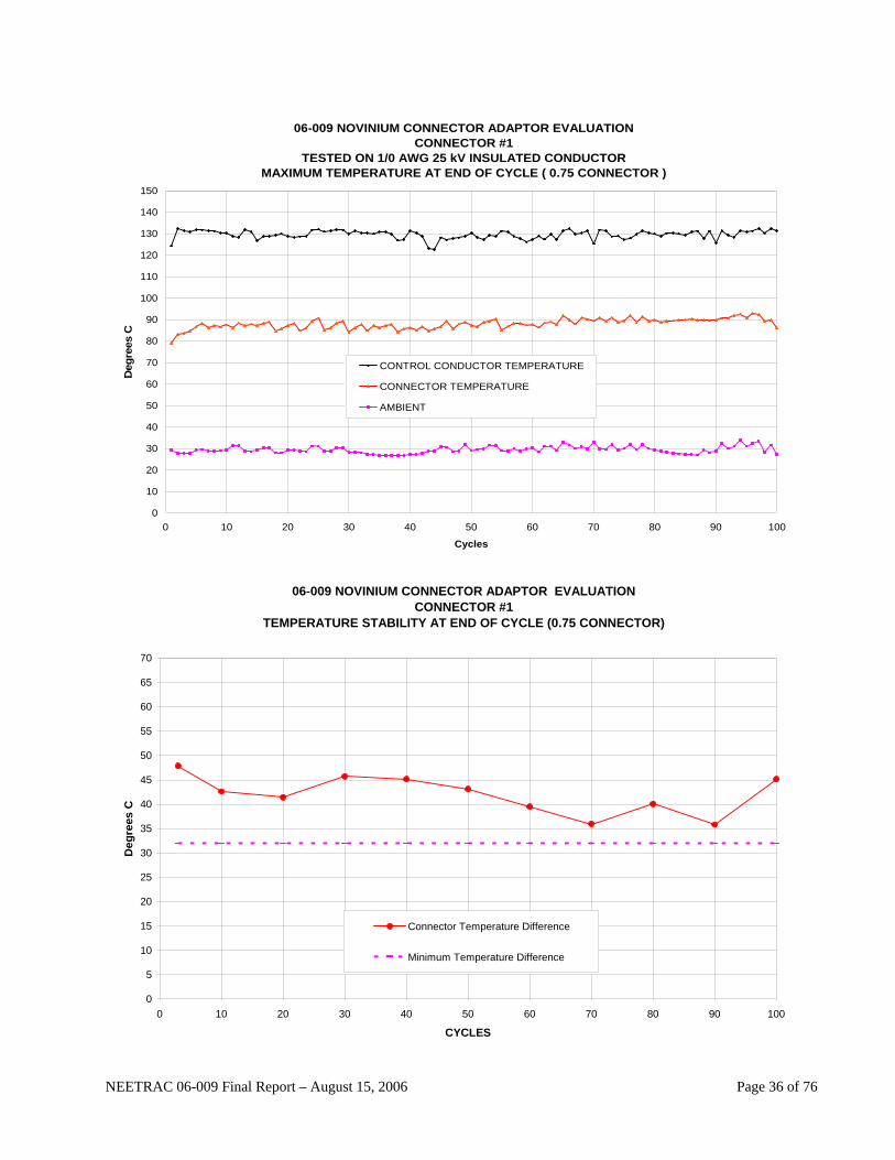
06-009 NOVINIUM CONNECTOR ADAPTOR EVALUATIONCONNECTOR #1
TESTED ON 1/0 AWG 25 kV INSULATED CONDUCTORMAXIMUM TEMPERATURE AT END OF CYCLE ( 0.75 CONNECTOR )
0
10
20
30
40
50
60
70
80
90
100
110
120
130
140
150
0 10 20 30 40 50 60 70 80 90 100
Cycles
Deg
rees
C
CONTROL CONDUCTOR TEMPERATURE
CONNECTOR TEMPERATURE
AMBIENT
06-009 NOVINIUM CONNECTOR ADAPTOR EVALUATION
CONNECTOR #1 TEMPERATURE STABILITY AT END OF CYCLE (0.75 CONNECTOR)
0
5
10
15
20
25
30
35
40
45
50
55
60
65
70
0 10 20 30 40 50 60 70 80 90 100
CYCLES
Deg
rees
C
Connector Temperature Difference
Minimum Temperature Difference
NEETRAC 06-009 Final Report – August 15, 2006 Page 36 of 76
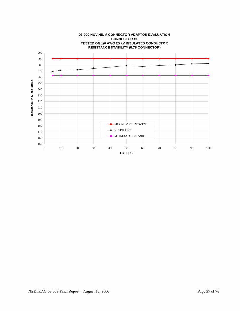
06-009 NOVINIUM CONNECTOR ADAPTOR EVALUATIONCONNECTOR #1
TESTED ON 1/0 AWG 25 kV INSULATED CONDUCTORRESISTANCE STABILITY (0.75 CONNECTOR)
150
160
170
180
190
200
210
220
230
240
250
260
270
280
290
300
0 10 20 30 40 50 60 70 80 90 100
CYCLES
Res
ista
nce
In M
icro
-ohm
s
MAXIMUM RESISTANCE
RESISTANCE
MINIMUM RESISTANCE
NEETRAC 06-009 Final Report – August 15, 2006 Page 37 of 76
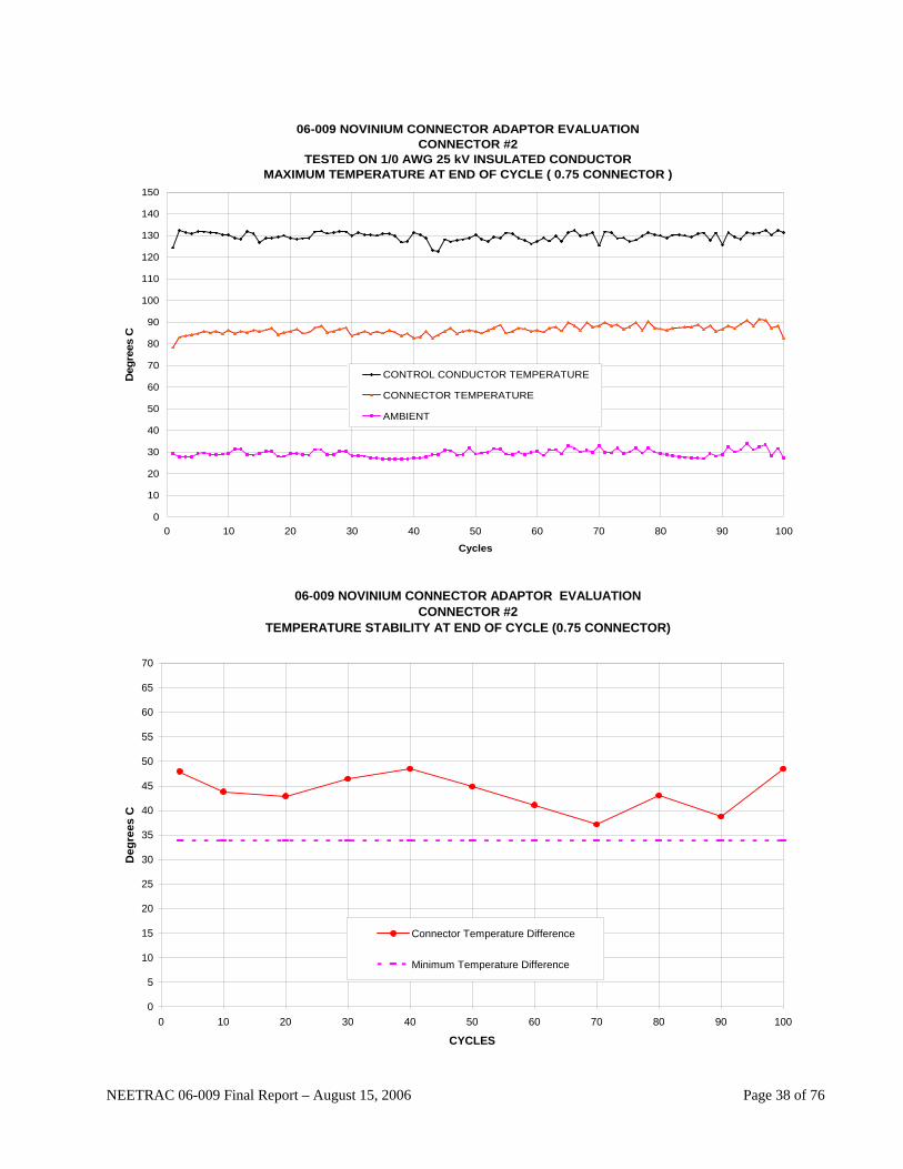
06-009 NOVINIUM CONNECTOR ADAPTOR EVALUATIONCONNECTOR #2
TESTED ON 1/0 AWG 25 kV INSULATED CONDUCTORMAXIMUM TEMPERATURE AT END OF CYCLE ( 0.75 CONNECTOR )
0
10
20
30
40
50
60
70
80
90
100
110
120
130
140
150
0 10 20 30 40 50 60 70 80 90 100
Cycles
Deg
rees
C
CONTROL CONDUCTOR TEMPERATURE
CONNECTOR TEMPERATURE
AMBIENT
06-009 NOVINIUM CONNECTOR ADAPTOR EVALUATION
CONNECTOR #2 TEMPERATURE STABILITY AT END OF CYCLE (0.75 CONNECTOR)
0
5
10
15
20
25
30
35
40
45
50
55
60
65
70
0 10 20 30 40 50 60 70 80 90 100
CYCLES
Deg
rees
C
Connector Temperature Difference
Minimum Temperature Difference
NEETRAC 06-009 Final Report – August 15, 2006 Page 38 of 76

06-009 NOVINIUM CONNECTOR ADAPTOR EVALUATIONCONNECTOR #2
TESTED ON 1/0 AWG 25 kV INSULATED CONDUCTORRESISTANCE STABILITY (0.75 CONNECTOR)
150
160
170
180
190
200
210
220
230
240
250
260
270
280
290
300
0 10 20 30 40 50 60 70 80 90 100
CYCLES
Res
ista
nce
In M
icro
-ohm
s
MAXIMUM RESISTANCE
RESISTANCE
MINIMUM RESISTANCE
NEETRAC 06-009 Final Report – August 15, 2006 Page 39 of 76
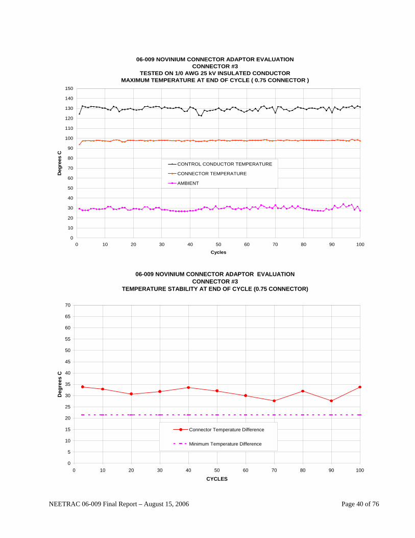
06-009 NOVINIUM CONNECTOR ADAPTOR EVALUATIONCONNECTOR #3
TESTED ON 1/0 AWG 25 kV INSULATED CONDUCTORMAXIMUM TEMPERATURE AT END OF CYCLE ( 0.75 CONNECTOR )
0
10
20
30
40
50
60
70
80
90
100
110
120
130
140
150
0 10 20 30 40 50 60 70 80 90 100
Cycles
Deg
rees
C
CONTROL CONDUCTOR TEMPERATURE
CONNECTOR TEMPERATURE
AMBIENT
06-009 NOVINIUM CONNECTOR ADAPTOR EVALUATION
CONNECTOR #3 TEMPERATURE STABILITY AT END OF CYCLE (0.75 CONNECTOR)
0
5
10
15
20
25
30
35
40
45
50
55
60
65
70
0 10 20 30 40 50 60 70 80 90 100
CYCLES
Deg
rees
C
Connector Temperature Difference
Minimum Temperature Difference
NEETRAC 06-009 Final Report – August 15, 2006 Page 40 of 76

06-009 NOVINIUM CONNECTOR ADAPTOR EVALUATIONCONNECTOR #3
TESTED ON 1/0 AWG 25 kV INSULATED CONDUCTORRESISTANCE STABILITY (0.75 CONNECTOR)
150
160
170
180
190
200
210
220
230
240
250
260
270
280
290
300
310
320
330
340
0 10 20 30 40 50 60 70 80 90 100
CYCLES
Res
ista
nce
In M
icro
-ohm
s
MAXIMUM RESISTANCE
RESISTANCE
MINIMUM RESISTANCE
NEETRAC 06-009 Final Report – August 15, 2006 Page 41 of 76

06-009 NOVINIUM CONNECTOR ADAPTOR EVALUATIONCONNECTOR #4
TESTED ON 1/0 AWG 25 kV INSULATED CONDUCTORMAXIMUM TEMPERATURE AT END OF CYCLE ( 0.75 CONNECTOR )
0
10
20
30
40
50
60
70
80
90
100
110
120
130
140
150
0 10 20 30 40 50 60 70 80 90 100
Cycles
Deg
rees
C
CONTROL CONDUCTOR TEMPERATURE
CONNECTOR TEMPERATURE
AMBIENT
06-009 NOVINIUM CONNECTOR ADAPTOR EVALUATION
CONNECTOR #4 TEMPERATURE STABILITY AT END OF CYCLE (0.75 CONNECTOR)
0
5
10
15
20
25
30
35
40
45
50
55
60
65
70
0 10 20 30 40 50 60 70 80 90 100
CYCLES
Deg
rees
C
Connector Temperature Difference
Minimum Temperature Difference
NEETRAC 06-009 Final Report – August 15, 2006 Page 42 of 76
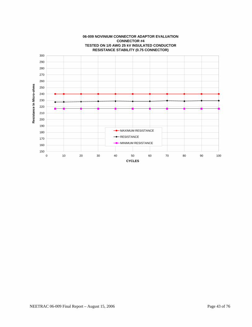
06-009 NOVINIUM CONNECTOR ADAPTOR EVALUATIONCONNECTOR #4
TESTED ON 1/0 AWG 25 kV INSULATED CONDUCTORRESISTANCE STABILITY (0.75 CONNECTOR)
150
160
170
180
190
200
210
220
230
240
250
260
270
280
290
300
0 10 20 30 40 50 60 70 80 90 100
CYCLES
Res
ista
nce
In M
icro
-ohm
s
MAXIMUM RESISTANCE
RESISTANCE
MINIMUM RESISTANCE
NEETRAC 06-009 Final Report – August 15, 2006 Page 43 of 76
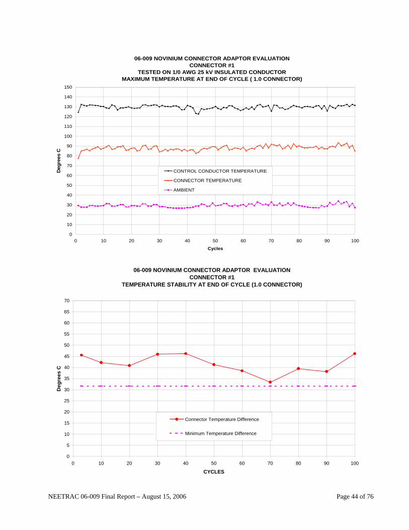
06-009 NOVINIUM CONNECTOR ADAPTOR EVALUATIONCONNECTOR #1
TESTED ON 1/0 AWG 25 kV INSULATED CONDUCTORMAXIMUM TEMPERATURE AT END OF CYCLE ( 1.0 CONNECTOR)
0
10
20
30
40
50
60
70
80
90
100
110
120
130
140
150
0 10 20 30 40 50 60 70 80 90 100
Cycles
Deg
rees
C
CONTROL CONDUCTOR TEMPERATURE
CONNECTOR TEMPERATURE
AMBIENT
06-009 NOVINIUM CONNECTOR ADAPTOR EVALUATION
CONNECTOR #1 TEMPERATURE STABILITY AT END OF CYCLE (1.0 CONNECTOR)
0
5
10
15
20
25
30
35
40
45
50
55
60
65
70
0 10 20 30 40 50 60 70 80 90 100
CYCLES
Deg
rees
C
Connector Temperature Difference
Minimum Temperature Difference
NEETRAC 06-009 Final Report – August 15, 2006 Page 44 of 76

06-009 NOVINIUM CONNECTOR ADAPTOR EVALUATIONCONNECTOR #1
TESTED ON 1/0 AWG 25 kV INSULATED CONDUCTORRESISTANCE STABILITY (1.0 CONNECTOR)
150
160
170
180
190
200
210
220
230
240
250
260
270
280
290
300
0 10 20 30 40 50 60 70 80 90 100
CYCLES
Res
ista
nce
In M
icro
-ohm
s
MAXIMUM RESISTANCE
RESISTANCE
MINIMUM RESISTANCE
NEETRAC 06-009 Final Report – August 15, 2006 Page 45 of 76

06-009 NOVINIUM CONNECTOR ADAPTOR EVALUATIONCONNECTOR #2
TESTED ON 1/0 AWG 25 kV INSULATED CONDUCTORMAXIMUM TEMPERATURE AT END OF CYCLE (1.0 CONNECTOR)
0
10
20
30
40
50
60
70
80
90
100
110
120
130
140
150
0 10 20 30 40 50 60 70 80 90 100
Cycles
Deg
rees
C
CONTROL CONDUCTOR TEMPERATURE
CONNECTOR TEMPERATURE
AMBIENT
06-009 NOVINIUM CONNECTOR ADAPTOR EVALUATION
CONNECTOR #2 TEMPERATURE STABILITY AT END OF CYCLE (1.0 CONNECTOR)
0
5
10
15
20
25
30
35
40
45
50
55
60
65
70
0 10 20 30 40 50 60 70 80 90 100
CYCLES
Deg
rees
C
Connector Temperature Difference
Minimum Temperature Difference
NEETRAC 06-009 Final Report – August 15, 2006 Page 46 of 76

06-009 NOVINIUM CONNECTOR ADAPTOR EVALUATIONCONNECTOR #2
TESTED ON 1/0 AWG 25 kV INSULATED CONDUCTORRESISTANCE STABILITY (1.0 CONNECTOR)
150
160
170
180
190
200
210
220
230
240
250
260
270
280
290
300
0 10 20 30 40 50 60 70 80 90 100
CYCLES
Res
ista
nce
In M
icro
-ohm
s
MAXIMUM RESISTANCE
RESISTANCE
MINIMUM RESISTANCE
NEETRAC 06-009 Final Report – August 15, 2006 Page 47 of 76
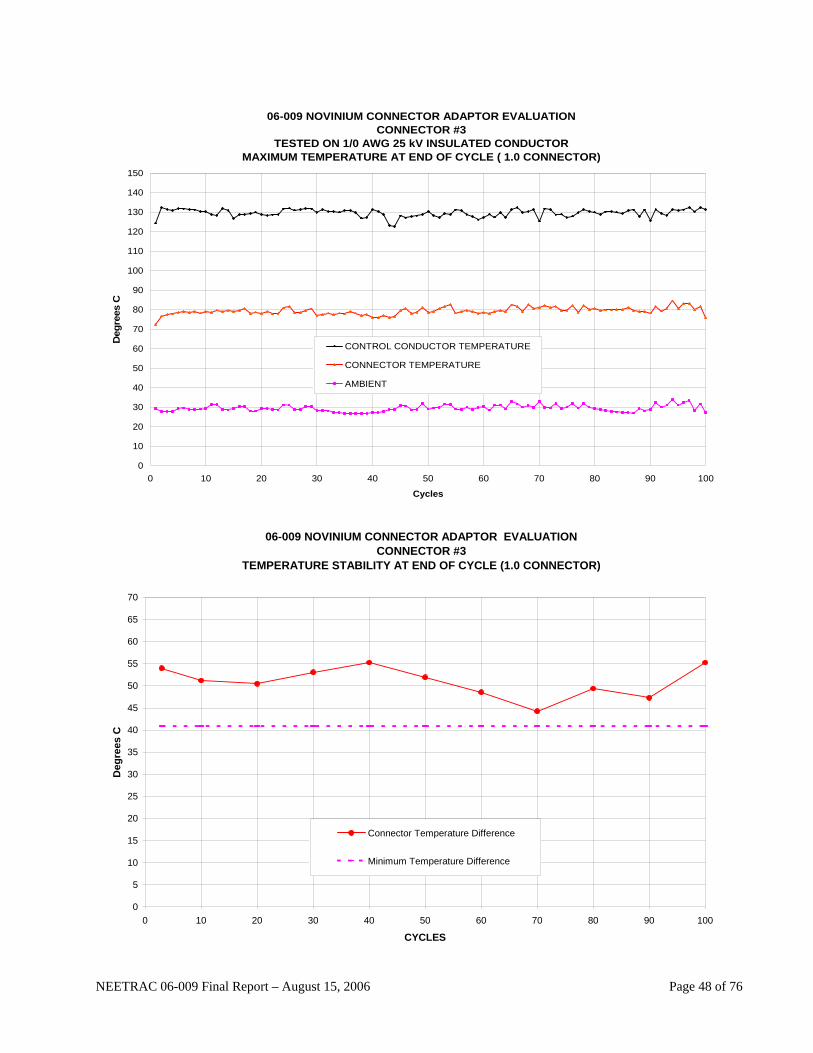
06-009 NOVINIUM CONNECTOR ADAPTOR EVALUATIONCONNECTOR #3
TESTED ON 1/0 AWG 25 kV INSULATED CONDUCTORMAXIMUM TEMPERATURE AT END OF CYCLE ( 1.0 CONNECTOR)
0
10
20
30
40
50
60
70
80
90
100
110
120
130
140
150
0 10 20 30 40 50 60 70 80 90 100
Cycles
Deg
rees
C
CONTROL CONDUCTOR TEMPERATURE
CONNECTOR TEMPERATURE
AMBIENT
06-009 NOVINIUM CONNECTOR ADAPTOR EVALUATION
CONNECTOR #3 TEMPERATURE STABILITY AT END OF CYCLE (1.0 CONNECTOR)
0
5
10
15
20
25
30
35
40
45
50
55
60
65
70
0 10 20 30 40 50 60 70 80 90 100
CYCLES
Deg
rees
C
Connector Temperature Difference
Minimum Temperature Difference
NEETRAC 06-009 Final Report – August 15, 2006 Page 48 of 76
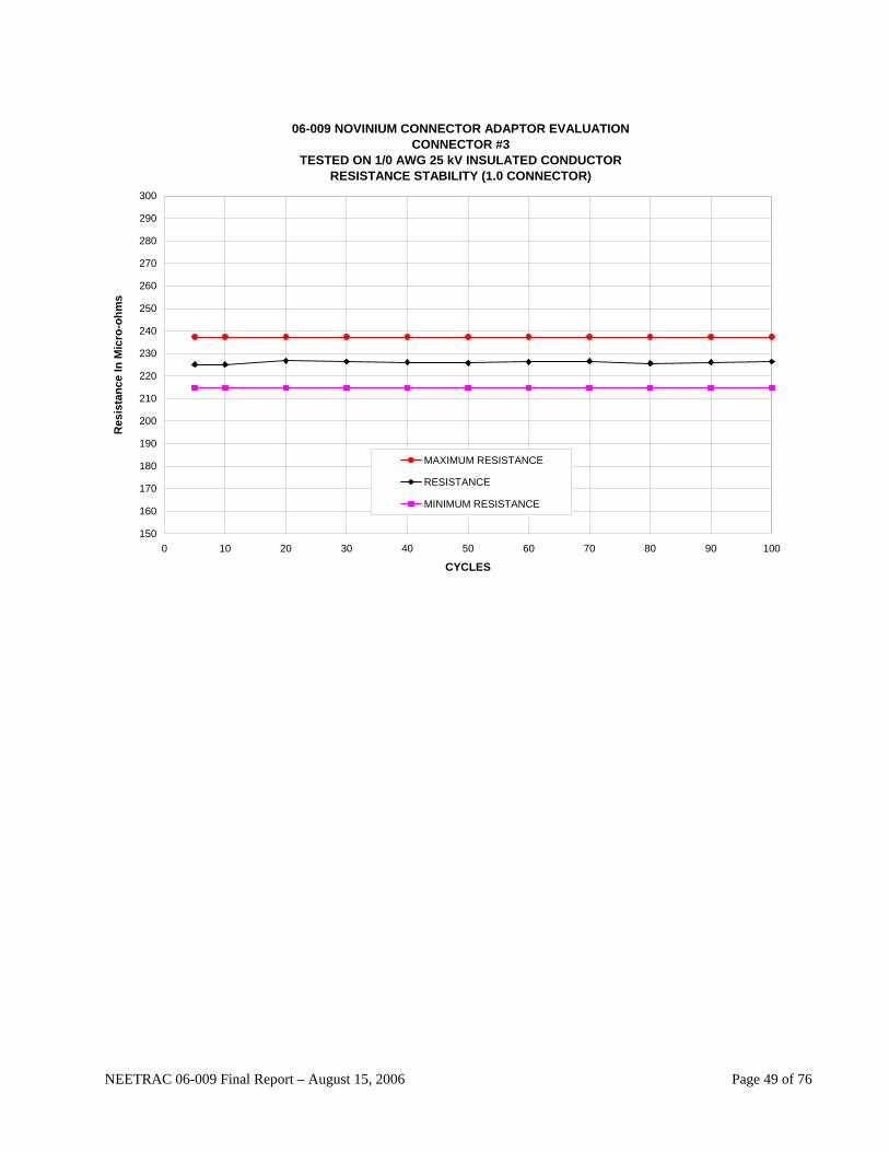
06-009 NOVINIUM CONNECTOR ADAPTOR EVALUATIONCONNECTOR #3
TESTED ON 1/0 AWG 25 kV INSULATED CONDUCTORRESISTANCE STABILITY (1.0 CONNECTOR)
150
160
170
180
190
200
210
220
230
240
250
260
270
280
290
300
0 10 20 30 40 50 60 70 80 90 100
CYCLES
Res
ista
nce
In M
icro
-ohm
s
MAXIMUM RESISTANCE
RESISTANCE
MINIMUM RESISTANCE
NEETRAC 06-009 Final Report – August 15, 2006 Page 49 of 76
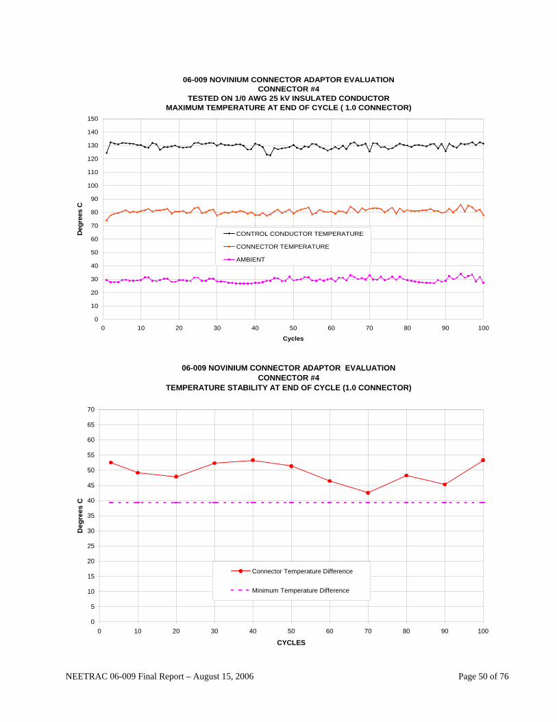
06-009 NOVINIUM CONNECTOR ADAPTOR EVALUATIONCONNECTOR #4
TESTED ON 1/0 AWG 25 kV INSULATED CONDUCTORMAXIMUM TEMPERATURE AT END OF CYCLE ( 1.0 CONNECTOR)
0
10
20
30
40
50
60
70
80
90
100
110
120
130
140
150
0 10 20 30 40 50 60 70 80 90 100
Cycles
Deg
rees
C
CONTROL CONDUCTOR TEMPERATURE
CONNECTOR TEMPERATURE
AMBIENT
06-009 NOVINIUM CONNECTOR ADAPTOR EVALUATION
CONNECTOR #4 TEMPERATURE STABILITY AT END OF CYCLE (1.0 CONNECTOR)
0
5
10
15
20
25
30
35
40
45
50
55
60
65
70
0 10 20 30 40 50 60 70 80 90 100
CYCLES
Deg
rees
C
Connector Temperature Difference
Minimum Temperature Difference
NEETRAC 06-009 Final Report – August 15, 2006 Page 50 of 76

06-009 NOVINIUM CONNECTOR ADAPTOR EVALUATIONCONNECTOR #4
TESTED ON 1/0 AWG 25 kV INSULATED CONDUCTORRESISTANCE STABILITY (1.0 CONNECTOR)
150
160
170
180
190
200
210
220
230
240
250
260
270
280
290
300
0 10 20 30 40 50 60 70 80 90 100
CYCLES
Res
ista
nce
In M
icro
-ohm
s
MAXIMUM RESISTANCE
RESISTANCE
MINIMUM RESISTANCE
NEETRAC 06-009 Final Report – August 15, 2006 Page 51 of 76

NEETRAC 06-009 Final Report – August 15, 2006 Page 52 of 76
GRAPHS FOR 1000 KCMIL CONNECTORS

06-009 NOVINIUM CONNECTOR ADAPTOR EVALUATIONCONNECTOR #1
TESTED ON 1000 MCM 25 kV INSULATED CONDUCTORMAXIMUM TEMPERATURE AT END OF CYCLE (STANDARD)
0
10
20
30
40
50
60
70
80
90
100
110
120
130
140
150
0 10 20 30 40 50 60 70 80 90 100
Cycles
Deg
rees
C
CONTROL CONDUCTOR TEMPERATURE
CONNECTOR TEMPERATURE
AMBIENT
06-009 NOVINIUM CONNECTOR ADAPTOR EVALUATION
1000 MCM CONNECTOR #1 TEMPERATURE STABILITY AT END OF CYCLE (STANDARD)
30
35
40
45
50
55
60
65
70
75
80
85
90
0 10 20 30 40 50 60 70 80 90 100
CYCLES
Deg
rees
C
Connector Temperature Difference
Minimum Temperature Difference
NEETRAC 06-009 Final Report – August 15, 2006 Page 53 of 76

06-009 NOVINIUM CONNECTOR ADAPTOR EVALUATIONCONNECTOR #1
TESTED ON 1000 MCM 25 kV INSULATED CONDUCTORRESISTANCE STABILITY (STANDARD)
40
45
50
55
60
65
70
75
0 10 20 30 40 50 60 70 80 90 100
CYCLES
Res
ista
nce
In M
icro
-ohm
s
MAXIMUM RESISTANCE
RESISTANCE
MINIMUM RESISTANCE
NEETRAC 06-009 Final Report – August 15, 2006 Page 54 of 76
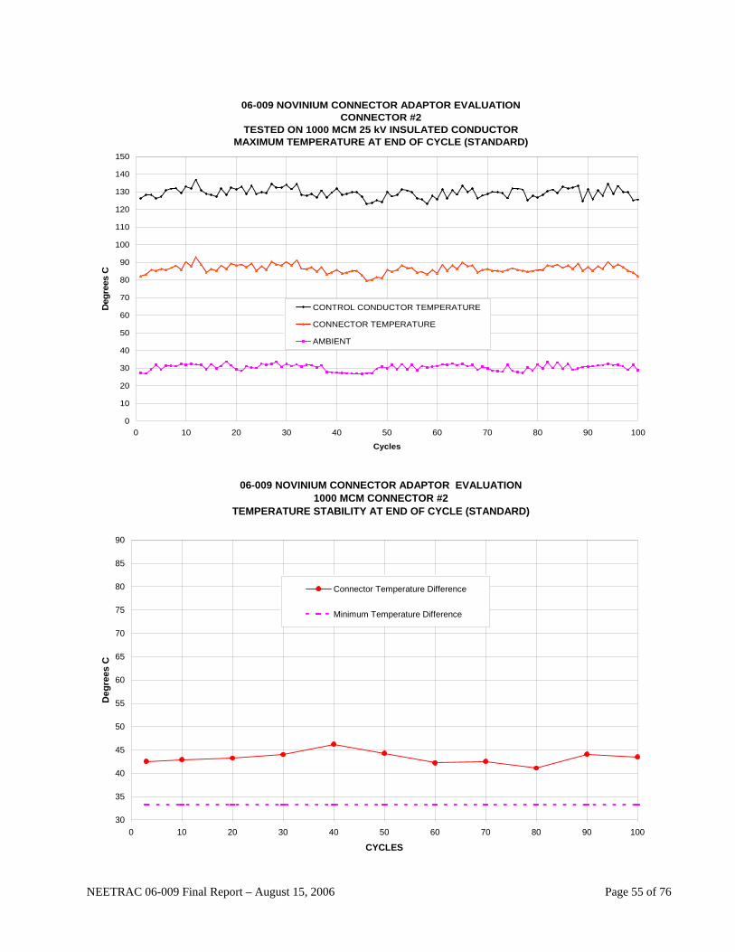
06-009 NOVINIUM CONNECTOR ADAPTOR EVALUATIONCONNECTOR #2
TESTED ON 1000 MCM 25 kV INSULATED CONDUCTORMAXIMUM TEMPERATURE AT END OF CYCLE (STANDARD)
0
10
20
30
40
50
60
70
80
90
100
110
120
130
140
150
0 10 20 30 40 50 60 70 80 90 100
Cycles
Deg
rees
C
CONTROL CONDUCTOR TEMPERATURE
CONNECTOR TEMPERATURE
AMBIENT
06-009 NOVINIUM CONNECTOR ADAPTOR EVALUATION
1000 MCM CONNECTOR #2 TEMPERATURE STABILITY AT END OF CYCLE (STANDARD)
30
35
40
45
50
55
60
65
70
75
80
85
90
0 10 20 30 40 50 60 70 80 90 100
CYCLES
Deg
rees
C
Connector Temperature Difference
Minimum Temperature Difference
NEETRAC 06-009 Final Report – August 15, 2006 Page 55 of 76

06-009 NOVINIUM CONNECTOR ADAPTOR EVALUATIONCONNECTOR #2
TESTED ON 1000 MCM 25 kV INSULATED CONDUCTORRESISTANCE STABILITY (STANDARD)
40
45
50
55
60
65
70
75
0 10 20 30 40 50 60 70 80 90 100
CYCLES
Res
ista
nce
In M
icro
-ohm
s
MAXIMUM RESISTANCE
RESISTANCE
MINIMUM RESISTANCE
NEETRAC 06-009 Final Report – August 15, 2006 Page 56 of 76

06-009 NOVINIUM CONNECTOR ADAPTOR EVALUATIONCONNECTOR #3
TESTED ON 1000 MCM 25 kV INSULATED CONDUCTORMAXIMUM TEMPERATURE AT END OF CYCLE (STANDARD)
0
10
20
30
40
50
60
70
80
90
100
110
120
130
140
150
0 10 20 30 40 50 60 70 80 90 100
Cycles
Deg
rees
C
CONTROL CONDUCTOR TEMPERATURE
CONNECTOR TEMPERATURE
AMBIENT
06-009 NOVINIUM CONNECTOR ADAPTOR EVALUATION
1000 MCM CONNECTOR #3 TEMPERATURE STABILITY AT END OF CYCLE (STANDARD)
30
35
40
45
50
55
60
65
70
75
80
85
90
0 10 20 30 40 50 60 70 80 90 100
CYCLES
Deg
rees
C
Connector Temperature Difference
Minimum Temperature Difference
NEETRAC 06-009 Final Report – August 15, 2006 Page 57 of 76
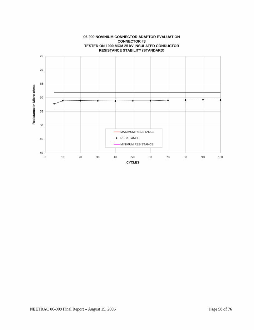
06-009 NOVINIUM CONNECTOR ADAPTOR EVALUATIONCONNECTOR #3
TESTED ON 1000 MCM 25 kV INSULATED CONDUCTORRESISTANCE STABILITY (STANDARD)
40
45
50
55
60
65
70
75
0 10 20 30 40 50 60 70 80 90 100
CYCLES
Res
ista
nce
In M
icro
-ohm
s
MAXIMUM RESISTANCE
RESISTANCE
MINIMUM RESISTANCE
NEETRAC 06-009 Final Report – August 15, 2006 Page 58 of 76

06-009 NOVINIUM CONNECTOR ADAPTOR EVALUATIONCONNECTOR #4
TESTED ON 1000 MCM 25 kV INSULATED CONDUCTORMAXIMUM TEMPERATURE AT END OF CYCLE (STANDARD)
0
10
20
30
40
50
60
70
80
90
100
110
120
130
140
150
0 10 20 30 40 50 60 70 80 90 100
Cycles
Deg
rees
C
CONTROL CONDUCTOR TEMPERATURE
CONNECTOR TEMPERATURE
AMBIENT
06-009 NOVINIUM CONNECTOR ADAPTOR EVALUATION
1000 MCM CONNECTOR #4 TEMPERATURE STABILITY AT END OF CYCLE (STANDARD)
30
35
40
45
50
55
60
65
70
75
80
85
90
0 10 20 30 40 50 60 70 80 90 100
CYCLES
Deg
rees
C
Connector Temperature Difference
Minimum Temperature Difference
NEETRAC 06-009 Final Report – August 15, 2006 Page 59 of 76
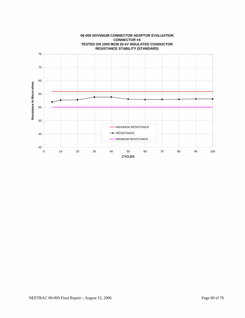
06-009 NOVINIUM CONNECTOR ADAPTOR EVALUATIONCONNECTOR #4
TESTED ON 1000 MCM 25 kV INSULATED CONDUCTORRESISTANCE STABILITY (STANDARD)
40
45
50
55
60
65
70
75
0 10 20 30 40 50 60 70 80 90 100
CYCLES
Res
ista
nce
In M
icro
-ohm
s
MAXIMUM RESISTANCE
RESISTANCE
MINIMUM RESISTANCE
NEETRAC 06-009 Final Report – August 15, 2006 Page 60 of 76

06-009 NOVINIUM CONNECTOR ADAPTOR EVALUATIONCONNECTOR #1
TESTED ON 1000 MCM 25 kV INSULATED CONDUCTORMAXIMUM TEMPERATURE AT END OF CYCLE (1.5 CONNECTOR )
0
10
20
30
40
50
60
70
80
90
100
110
120
130
140
150
0 10 20 30 40 50 60 70 80 90 100
Cycles
Deg
rees
C
CONTROL CONDUCTOR TEMPERATURE
CONNECTOR TEMPERATURE
AMBIENT
NEETRAC 06-009 Final Report – August 15, 2006 Page 61 of 76
06-009 NOVINIUM CONNECTOR ADAPTOR EVALUATION1000 MCM CONNECTOR #1
TEMPERATURE STABILITY AT END OF CYCLE (1.5 CONNECTOR)
30
35
40
45
50
55
60
65
70
75
80
85
90
0 10 20 30 40 50 60 70 80 90 100
CYCLES
Deg
rees
C
Connector Temperature Difference
Minimum Temperature Difference

06-009 NOVINIUM CONNECTOR ADAPTOR EVALUATIONCONNECTOR #1
TESTED ON 1000 MCM 25 kV INSULATED CONDUCTORRESISTANCE STABILITY (1.5 CONNECTOR)
40
45
50
55
60
65
70
75
0 10 20 30 40 50 60 70 80 90 100
CYCLES
Res
ista
nce
In M
icro
-ohm
s
MAXIMUM RESISTANCE
RESISTANCE
MINIMUM RESISTANCE
NEETRAC 06-009 Final Report – August 15, 2006 Page 62 of 76
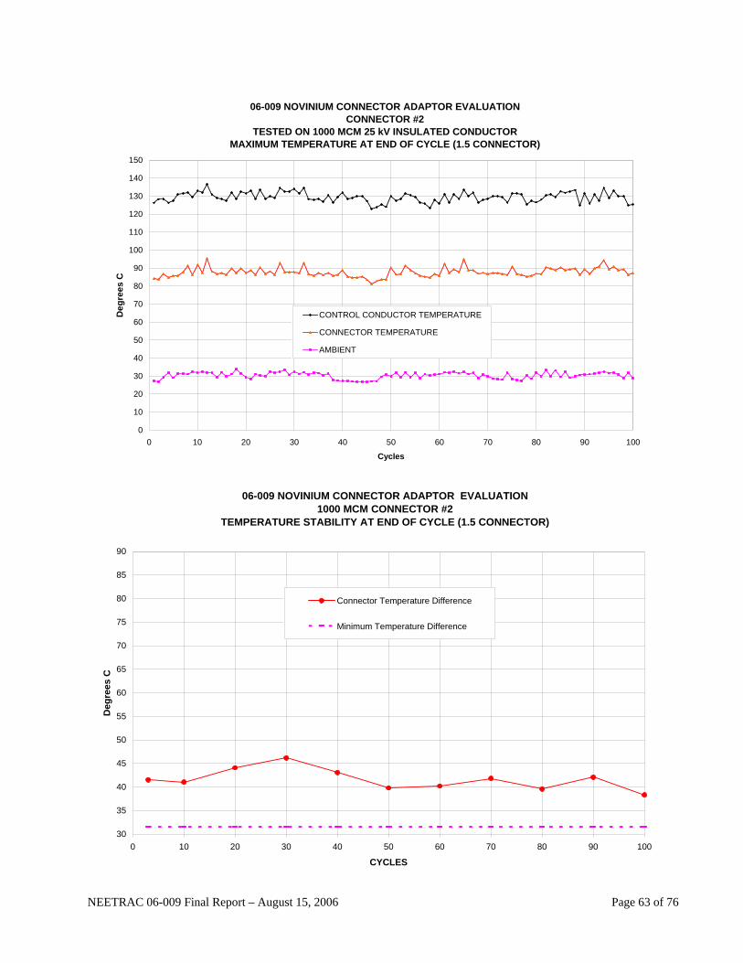
06-009 NOVINIUM CONNECTOR ADAPTOR EVALUATIONCONNECTOR #2
TESTED ON 1000 MCM 25 kV INSULATED CONDUCTORMAXIMUM TEMPERATURE AT END OF CYCLE (1.5 CONNECTOR)
0
10
20
30
40
50
60
70
80
90
100
110
120
130
140
150
0 10 20 30 40 50 60 70 80 90 100
Cycles
Deg
rees
C
CONTROL CONDUCTOR TEMPERATURE
CONNECTOR TEMPERATURE
AMBIENT
06-009 NOVINIUM CONNECTOR ADAPTOR EVALUATION
1000 MCM CONNECTOR #2 TEMPERATURE STABILITY AT END OF CYCLE (1.5 CONNECTOR)
30
35
40
45
50
55
60
65
70
75
80
85
90
0 10 20 30 40 50 60 70 80 90 100
CYCLES
Deg
rees
C
Connector Temperature Difference
Minimum Temperature Difference
NEETRAC 06-009 Final Report – August 15, 2006 Page 63 of 76

06-009 NOVINIUM CONNECTOR ADAPTOR EVALUATIONCONNECTOR #2
TESTED ON 1000 MCM 25 kV INSULATED CONDUCTORRESISTANCE STABILITY (1.5 CONNECTOR)
40
45
50
55
60
65
70
75
0 10 20 30 40 50 60 70 80 90 100
CYCLES
Res
ista
nce
In M
icro
-ohm
s
MAXIMUM RESISTANCE
RESISTANCE
MINIMUM RESISTANCE
NEETRAC 06-009 Final Report – August 15, 2006 Page 64 of 76

06-009 NOVINIUM CONNECTOR ADAPTOR EVALUATIONCONNECTOR #3
TESTED ON 1000 MCM 25 kV INSULATED CONDUCTORMAXIMUM TEMPERATURE AT END OF CYCLE (1.5 CONNECTOR)
0
10
20
30
40
50
60
70
80
90
100
110
120
130
140
150
0 10 20 30 40 50 60 70 80 90 100
Cycles
Deg
rees
C
CONTROL CONDUCTOR TEMPERATURE
CONNECTOR TEMPERATURE
AMBIENT
06-009 NOVINIUM CONNECTOR ADAPTOR EVALUATION
1000 MCM CONNECTOR #3 TEMPERATURE STABILITY AT END OF CYCLE (1.5 CONNECTOR)
30
35
40
45
50
55
60
65
70
75
80
85
90
0 10 20 30 40 50 60 70 80 90 100
CYCLES
Deg
rees
C
Connector Temperature Difference
Minimum Temperature Difference
NEETRAC 06-009 Final Report – August 15, 2006 Page 65 of 76

06-009 NOVINIUM CONNECTOR ADAPTOR EVALUATIONCONNECTOR #3
TESTED ON 1000 MCM 25 kV INSULATED CONDUCTORRESISTANCE STABILITY (1.5 CONNECTOR)
40
45
50
55
60
65
70
75
0 10 20 30 40 50 60 70 80 90 100
CYCLES
Res
ista
nce
In M
icro
-ohm
s
MAXIMUM RESISTANCE
RESISTANCE
MINIMUM RESISTANCE
NEETRAC 06-009 Final Report – August 15, 2006 Page 66 of 76

06-009 NOVINIUM CONNECTOR ADAPTOR EVALUATIONCONNECTOR #4
TESTED ON 1000 MCM 25 kV INSULATED CONDUCTORMAXIMUM TEMPERATURE AT END OF CYCLE (1.5 CONNECTOR)
0
10
20
30
40
50
60
70
80
90
100
110
120
130
140
150
0 10 20 30 40 50 60 70 80 90 100
Cycles
Deg
rees
C
CONTROL CONDUCTOR TEMPERATURE
CONNECTOR TEMPERATURE
AMBIENT
06-009 NOVINIUM CONNECTOR ADAPTOR EVALUATION
1000 MCM CONNECTOR #4 TEMPERATURE STABILITY AT END OF CYCLE (1.5 CONNECTOR)
30
35
40
45
50
55
60
65
70
75
80
85
90
0 10 20 30 40 50 60 70 80 90 100
CYCLES
Deg
rees
C
Connector Temperature Difference
Minimum Temperature Difference
NEETRAC 06-009 Final Report – August 15, 2006 Page 67 of 76
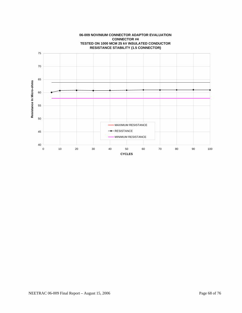
06-009 NOVINIUM CONNECTOR ADAPTOR EVALUATIONCONNECTOR #4
TESTED ON 1000 MCM 25 kV INSULATED CONDUCTORRESISTANCE STABILITY (1.5 CONNECTOR)
40
45
50
55
60
65
70
75
0 10 20 30 40 50 60 70 80 90 100
CYCLES
Res
ista
nce
In M
icro
-ohm
s
MAXIMUM RESISTANCE
RESISTANCE
MINIMUM RESISTANCE
NEETRAC 06-009 Final Report – August 15, 2006 Page 68 of 76

06-009 NOVINIUM CONNECTOR ADAPTOR EVALUATIONCONNECTOR #1
TESTED ON 1000 MCM 25 kV INSULATED CONDUCTORMAXIMUM TEMPERATURE AT END OF CYCLE (2.5 CONNECTOR)
0
10
20
30
40
50
60
70
80
90
100
110
120
130
140
150
0 10 20 30 40 50 60 70 80 90 100
Cycles
Deg
rees
C
CONTROL CONDUCTOR TEMPERATURE
CONNECTOR TEMPERATURE
AMBIENT
06-009 NOVINIUM CONNECTOR ADAPTOR EVALUATION
1000 MCM CONNECTOR #1 TEMPERATURE STABILITY AT END OF CYCLE (2.5 CONNECTOR)
30
35
40
45
50
55
60
65
70
75
80
85
90
0 10 20 30 40 50 60 70 80 90 100
CYCLES
Deg
rees
C
Connector Temperature Difference
Minimum Temperature Difference
NEETRAC 06-009 Final Report – August 15, 2006 Page 69 of 76
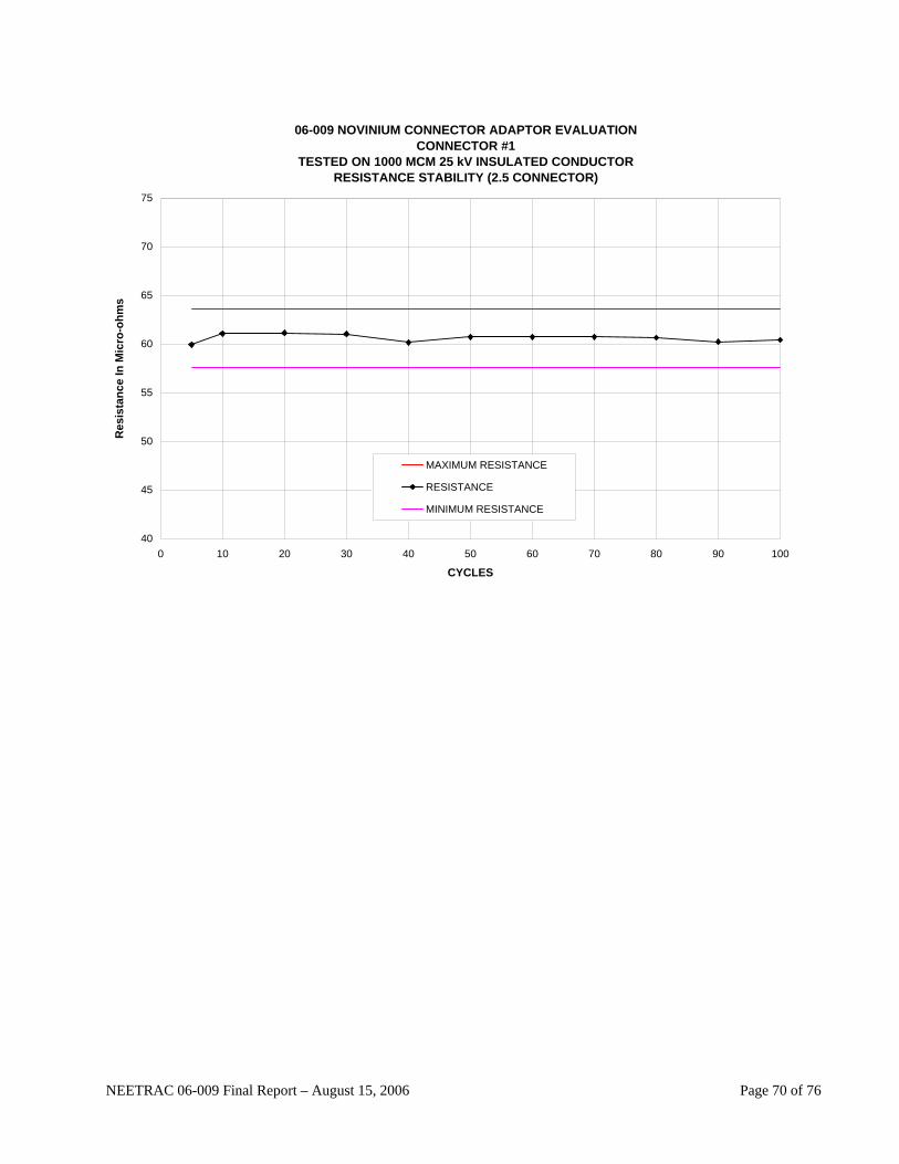
06-009 NOVINIUM CONNECTOR ADAPTOR EVALUATIONCONNECTOR #1
TESTED ON 1000 MCM 25 kV INSULATED CONDUCTORRESISTANCE STABILITY (2.5 CONNECTOR)
40
45
50
55
60
65
70
75
0 10 20 30 40 50 60 70 80 90 100
CYCLES
Res
ista
nce
In M
icro
-ohm
s
MAXIMUM RESISTANCE
RESISTANCE
MINIMUM RESISTANCE
NEETRAC 06-009 Final Report – August 15, 2006 Page 70 of 76
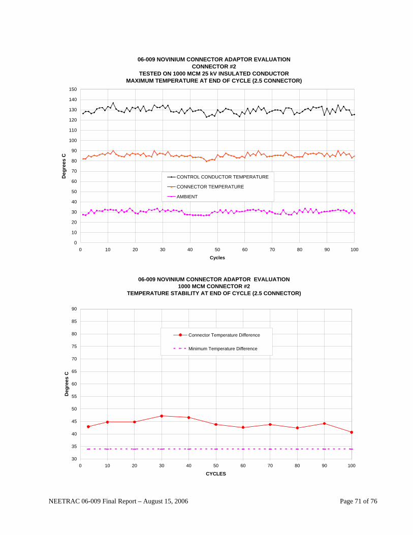
06-009 NOVINIUM CONNECTOR ADAPTOR EVALUATIONCONNECTOR #2
TESTED ON 1000 MCM 25 kV INSULATED CONDUCTORMAXIMUM TEMPERATURE AT END OF CYCLE (2.5 CONNECTOR)
0
10
20
30
40
50
60
70
80
90
100
110
120
130
140
150
0 10 20 30 40 50 60 70 80 90 100
Cycles
Deg
rees
C
CONTROL CONDUCTOR TEMPERATURE
CONNECTOR TEMPERATURE
AMBIENT
06-009 NOVINIUM CONNECTOR ADAPTOR EVALUATION
1000 MCM CONNECTOR #2 TEMPERATURE STABILITY AT END OF CYCLE (2.5 CONNECTOR)
30
35
40
45
50
55
60
65
70
75
80
85
90
0 10 20 30 40 50 60 70 80 90 100
CYCLES
Deg
rees
C
Connector Temperature Difference
Minimum Temperature Difference
NEETRAC 06-009 Final Report – August 15, 2006 Page 71 of 76

06-009 NOVINIUM CONNECTOR ADAPTOR EVALUATIONCONNECTOR #2
TESTED ON 1000 MCM 25 kV INSULATED CONDUCTORRESISTANCE STABILITY (2.5 CONNECTOR)
40
45
50
55
60
65
70
75
0 10 20 30 40 50 60 70 80 90 100
CYCLES
Res
ista
nce
In M
icro
-ohm
s
MAXIMUM RESISTANCE
RESISTANCE
MINIMUM RESISTANCE
NEETRAC 06-009 Final Report – August 15, 2006 Page 72 of 76
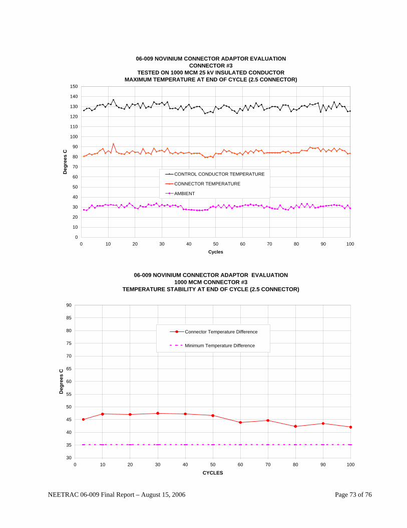
06-009 NOVINIUM CONNECTOR ADAPTOR EVALUATIONCONNECTOR #3
TESTED ON 1000 MCM 25 kV INSULATED CONDUCTORMAXIMUM TEMPERATURE AT END OF CYCLE (2.5 CONNECTOR)
0
10
20
30
40
50
60
70
80
90
100
110
120
130
140
150
0 10 20 30 40 50 60 70 80 90 100
Cycles
Deg
rees
C
CONTROL CONDUCTOR TEMPERATURE
CONNECTOR TEMPERATURE
AMBIENT
06-009 NOVINIUM CONNECTOR ADAPTOR EVALUATION
1000 MCM CONNECTOR #3 TEMPERATURE STABILITY AT END OF CYCLE (2.5 CONNECTOR)
30
35
40
45
50
55
60
65
70
75
80
85
90
0 10 20 30 40 50 60 70 80 90 100
CYCLES
Deg
rees
C
Connector Temperature Difference
Minimum Temperature Difference
NEETRAC 06-009 Final Report – August 15, 2006 Page 73 of 76

06-009 NOVINIUM CONNECTOR ADAPTOR EVALUATIONCONNECTOR #3
TESTED ON 1000 MCM 25 kV INSULATED CONDUCTORRESISTANCE STABILITY (2.5 CONNECTOR)
40
45
50
55
60
65
70
75
0 10 20 30 40 50 60 70 80 90 100
CYCLES
Res
ista
nce
In M
icro
-ohm
s
MAXIMUM RESISTANCE
RESISTANCE
MINIMUM RESISTANCE
NEETRAC 06-009 Final Report – August 15, 2006 Page 74 of 76
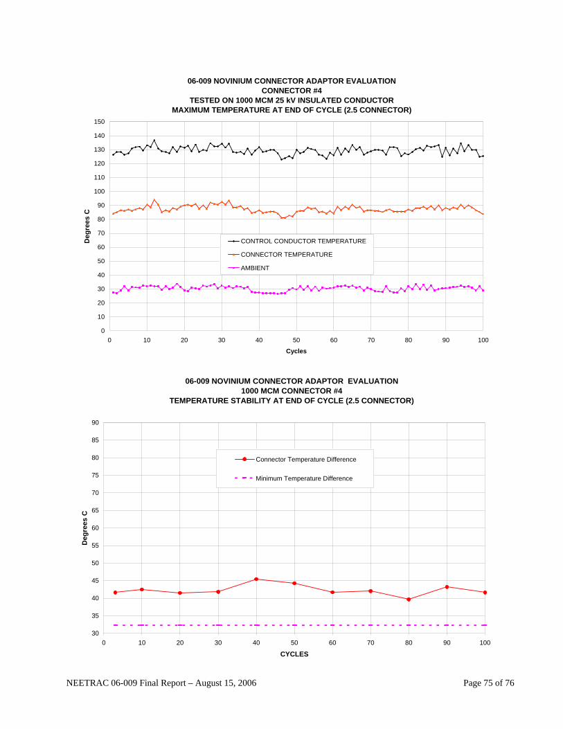
06-009 NOVINIUM CONNECTOR ADAPTOR EVALUATIONCONNECTOR #4
TESTED ON 1000 MCM 25 kV INSULATED CONDUCTORMAXIMUM TEMPERATURE AT END OF CYCLE (2.5 CONNECTOR)
0
10
20
30
40
50
60
70
80
90
100
110
120
130
140
150
0 10 20 30 40 50 60 70 80 90 100
Cycles
Deg
rees
C
CONTROL CONDUCTOR TEMPERATURE
CONNECTOR TEMPERATURE
AMBIENT
06-009 NOVINIUM CONNECTOR ADAPTOR EVALUATION
1000 MCM CONNECTOR #4 TEMPERATURE STABILITY AT END OF CYCLE (2.5 CONNECTOR)
30
35
40
45
50
55
60
65
70
75
80
85
90
0 10 20 30 40 50 60 70 80 90 100
CYCLES
Deg
rees
C
Connector Temperature Difference
Minimum Temperature Difference
NEETRAC 06-009 Final Report – August 15, 2006 Page 75 of 76
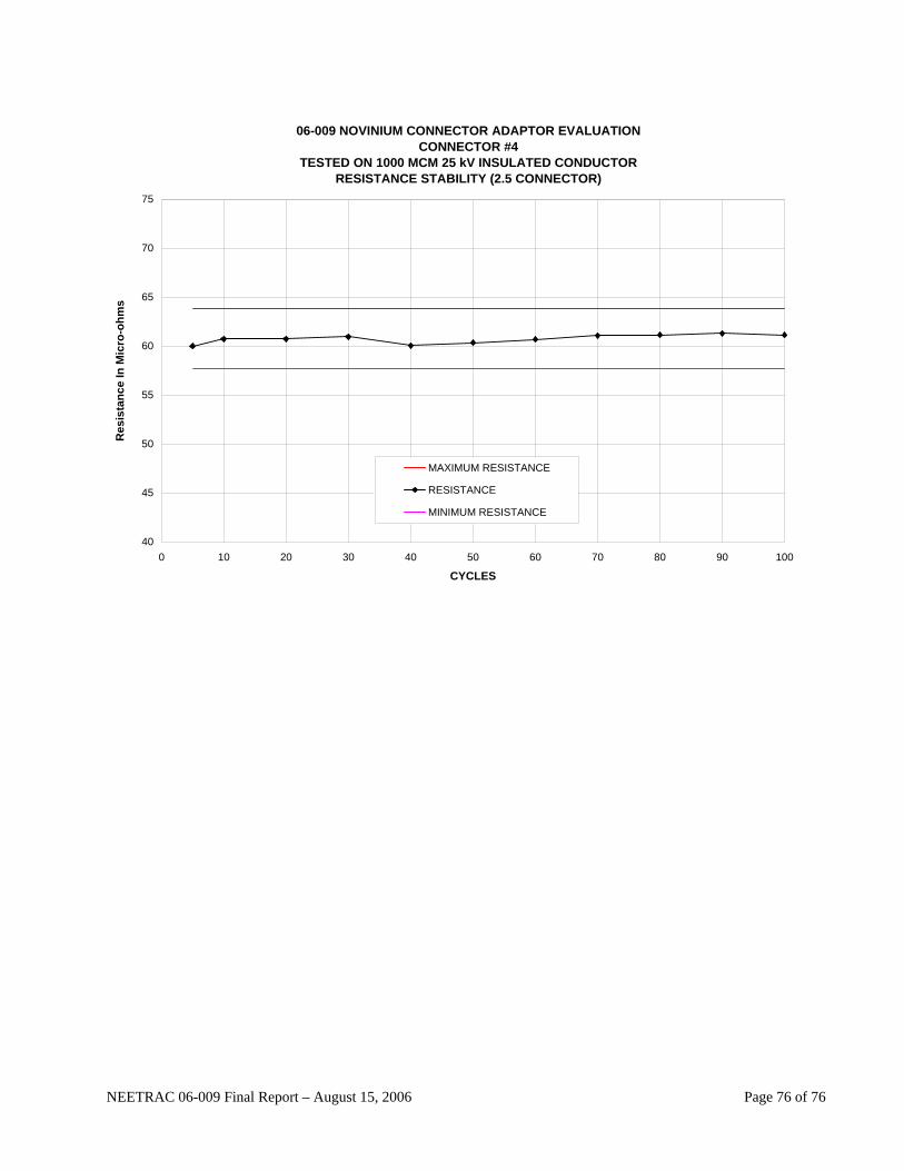
06-009 NOVINIUM CONNECTOR ADAPTOR EVALUATIONCONNECTOR #4
TESTED ON 1000 MCM 25 kV INSULATED CONDUCTORRESISTANCE STABILITY (2.5 CONNECTOR)
40
45
50
55
60
65
70
75
0 10 20 30 40 50 60 70 80 90 100
CYCLES
Res
ista
nce
In M
icro
-ohm
s
MAXIMUM RESISTANCE
RESISTANCE
MINIMUM RESISTANCE
NEETRAC 06-009 Final Report – August 15, 2006 Page 76 of 76
Related Documents


