Wear 266 (2009) 646–657 Contents lists available at ScienceDirect Wear journal homepage: www.elsevier.com/locate/wear Novel polytetrafluoroethylene (PTFE) composites with newly developed Tribaloy alloy additive for sliding bearings Alireza Khoddamzadeh a , Rong Liu a,∗ , Xijia Wu b a Department of Mechanical and Aerospace Engineering, Carleton University, 1125 Colonel By Drive, Ottawa, Ontario, Canada K1S 5B6 b Institute for Aerospace Research, National Research Council of Canada, 1200 Montreal Road, Ottawa, Ontario, Canada K1A 0R6 article info Article history: Received 8 November 2007 Received in revised form 18 June 2008 Accepted 7 August 2008 Available online 1 October 2008 Keywords: Sliding wear Tribaloy alloy Hardness Polymer–matrix composite Bearings abstract A group of novel polytetrafluoroethylene (PTFE)-based composite materials are developed for sliding bear- ing applications. The reinforcements include the newly developed T-401 Tribaloy alloy, which possesses better ductility compared to conventional Tribaloy alloys, spherical bronze particles, chopped carbon fibers and milled graphite. The specimens are fabricated with the compression moulding technique under different preforming and sintering cycles. The mechanical and tribological properties as well as corrosion resistance of the new composites are investigated. It is demonstrated that these properties are influenced by the type of fillers and the content level of fillers. The wear resistances of all the developed PTFE com- posites are much higher than that of pure PTFE with very low coefficients of friction. Among the developed composites, the mixture of 40% PTFE + 15% T-401 + 45% bronze exhibits the best combination of properties. © 2008 Elsevier B.V. All rights reserved. 1. Introduction Bearings are typical devices utilized to control friction by sepa- rating the moving surfaces. In sliding bearings loads are carried via sliding actions and predominantly sliding contact occurs between relatively moving surfaces. Thus a variety of liquid lubricants including oil, grease, and water are simultaneously used with bearings to effectively lessen the friction and allow easier slid- ing. However, liquid lubricants have usage difficulties in sliding bearings for many reasons [1–3]. For example, liquid lubrication sometimes requires complicated housing design with need for oil- ways or lubricant nipples, which increases the overall cost; most of the lubricants can be used in very limited operational temperatures. As a result, there was a strong desire among bearing designers to produce sliding bearings that successfully reduce friction without employing any liquid lubricants. This desire promoted the develop- ment of self-lubricating sliding bearings, which are independent of external liquid lubrication. In these types of bearings, liquid lubricants are replaced by self-lubricating materials. Self-lubricants are any solid materials that show low friction without application of liquid lubricants. Graphite, molybdenum disulfide (MoS 2 ), and boron nitride (BN) are the predominant materials used as solid lubricants. These materials are introduced between two rubbing ∗ Corresponding author. Tel.: +1 613 5202600x8397; fax: +1 613 5205715. E-mail address: [email protected] (R. Liu). surfaces for the purpose of reducing friction and providing pro- tection from damages that may happen during relative movement [4–6]. Due to excellent characteristics such as low cost, good lubricity, low weight, and high corrosion resistance, many polymers includ- ing nylon, acetal, and polyethylene are used as bearing materials. Among polymeric materials, polytetrafluoroethylene (PTFE), which is a synthetic fluoropolymer, is considered as a remarkable solid lubricant. Exhibiting the smallest coefficients of static and dynamic friction of any known solid materials, PTFE has been widely used as a self-lubricant. However, while showing excellent antifriction properties, PTFE suffers from a high wear rate that greatly limits its application [1]. Therefore, considerable efforts have been made to reduce wear damage by developing PTFE composites [7–13]. In these composites, PTFE is used as the thermoplastic resin matrix that is incorporated with many types of additives including organic and inorganic fillers as reinforcements. In this research, novel PTFE composites are developed with newly developed Tribaloy alloy T-401 additive for sliding bearing applications. Conventional PTFE reinforcements such as bronze, carbon and graphite are incorporated with the new alloy parti- cles to enhance the wear resistance of PTFE. Bronze is selected due to its high thermal conductivity, good anticorrosive and antifric- tion properties. Also, the bronze filled PTFE materials can be easily machined that keeps the overall cost of the bearings very low. Carbon and graphite are interchangeably used. Carbon fibers can increase load capacity of bearings and other mechanical proper- 0043-1648/$ – see front matter © 2008 Elsevier B.V. All rights reserved. doi:10.1016/j.wear.2008.08.007

Welcome message from author
This document is posted to help you gain knowledge. Please leave a comment to let me know what you think about it! Share it to your friends and learn new things together.
Transcript
Wear 266 (2009) 646–657
Contents lists available at ScienceDirect
Wear
journa l homepage: www.e lsev ier .com/ locate /wear
Novel polytetrafluoroethylene (PTFE) composites with newly developedTribaloy alloy additive for sliding bearings
Alireza Khoddamzadeha, Rong Liua,∗, Xijia Wub
a Department of Mechanical and Aerospace Engineering, Carleton University, 1125 Colonel By Drive, Ottawa, Ontario, Canada K1S 5B6b Institute for Aerospace Research, National Research Council of Canada, 1200 Montreal Road, Ottawa, Ontario, Canada K1A 0R6
a r t i c l e i n f o
Article history:Received 8 November 2007Received in revised form 18 June 2008Accepted 7 August 2008Available online 1 October 2008
Keywords:Sliding wear
a b s t r a c t
A group of novel polytetrafluoroethylene (PTFE)-based composite materials are developed for sliding bear-ing applications. The reinforcements include the newly developed T-401 Tribaloy alloy, which possessesbetter ductility compared to conventional Tribaloy alloys, spherical bronze particles, chopped carbonfibers and milled graphite. The specimens are fabricated with the compression moulding technique underdifferent preforming and sintering cycles. The mechanical and tribological properties as well as corrosionresistance of the new composites are investigated. It is demonstrated that these properties are influencedby the type of fillers and the content level of fillers. The wear resistances of all the developed PTFE com-
Tribaloy alloy posites are much higher than that of pure PTFE with very low coefficients of friction. Among the developed40% PTFE + 15% T-401 + 45% bronze exhibits the best combination of properties.
HardnessPolymer–matrix compositeBearings
composites, the mixture of
1. Introduction
Bearings are typical devices utilized to control friction by sepa-rating the moving surfaces. In sliding bearings loads are carried viasliding actions and predominantly sliding contact occurs betweenrelatively moving surfaces. Thus a variety of liquid lubricantsincluding oil, grease, and water are simultaneously used withbearings to effectively lessen the friction and allow easier slid-ing. However, liquid lubricants have usage difficulties in slidingbearings for many reasons [1–3]. For example, liquid lubricationsometimes requires complicated housing design with need for oil-ways or lubricant nipples, which increases the overall cost; most ofthe lubricants can be used in very limited operational temperatures.As a result, there was a strong desire among bearing designers toproduce sliding bearings that successfully reduce friction withoutemploying any liquid lubricants. This desire promoted the develop-ment of self-lubricating sliding bearings, which are independentof external liquid lubrication. In these types of bearings, liquidlubricants are replaced by self-lubricating materials. Self-lubricants
are any solid materials that show low friction without applicationof liquid lubricants. Graphite, molybdenum disulfide (MoS2), andboron nitride (BN) are the predominant materials used as solidlubricants. These materials are introduced between two rubbing∗ Corresponding author. Tel.: +1 613 5202600x8397; fax: +1 613 5205715.E-mail address: [email protected] (R. Liu).
0043-1648/$ – see front matter © 2008 Elsevier B.V. All rights reserved.doi:10.1016/j.wear.2008.08.007
© 2008 Elsevier B.V. All rights reserved.
surfaces for the purpose of reducing friction and providing pro-tection from damages that may happen during relative movement[4–6].
Due to excellent characteristics such as low cost, good lubricity,low weight, and high corrosion resistance, many polymers includ-ing nylon, acetal, and polyethylene are used as bearing materials.Among polymeric materials, polytetrafluoroethylene (PTFE), whichis a synthetic fluoropolymer, is considered as a remarkable solidlubricant. Exhibiting the smallest coefficients of static and dynamicfriction of any known solid materials, PTFE has been widely usedas a self-lubricant. However, while showing excellent antifrictionproperties, PTFE suffers from a high wear rate that greatly limitsits application [1]. Therefore, considerable efforts have been madeto reduce wear damage by developing PTFE composites [7–13]. Inthese composites, PTFE is used as the thermoplastic resin matrixthat is incorporated with many types of additives including organicand inorganic fillers as reinforcements.
In this research, novel PTFE composites are developed withnewly developed Tribaloy alloy T-401 additive for sliding bearingapplications. Conventional PTFE reinforcements such as bronze,carbon and graphite are incorporated with the new alloy parti-cles to enhance the wear resistance of PTFE. Bronze is selected due
to its high thermal conductivity, good anticorrosive and antifric-tion properties. Also, the bronze filled PTFE materials can be easilymachined that keeps the overall cost of the bearings very low.Carbon and graphite are interchangeably used. Carbon fibers canincrease load capacity of bearings and other mechanical proper-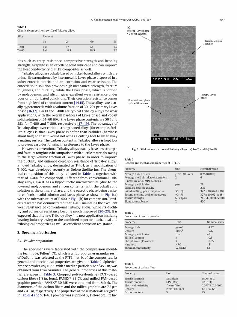
A. Khoddamzadeh et al. / Wear 266 (2009) 646–657 647
Table 1Chemical compositions (wt.%) of Tribaloy alloys
Alloy Element
TT
tst
psetbpfapas5Tlaat
attaTitalstwowiebt
2
2
iogborcgdai
Fig. 1. SEM microstructures of Tribaloy alloys: (a) T-401 and (b) T-400.
Table 2General and mechanical properties of PTFE 7C
Property Unit Nominal value
Average bulk density g/cm3 (lb/in.3) 0.25 (0.009)Average mold shrinkage (at preform
pressure of 35 MPa, 5000 psi)% 6
Average particle size �m 28Standard specific gravity – 2.16Initial melting, peak temperature ◦C (◦F) 342 ± 10 (648 ± 18)Second melting, peak temperature ◦C (◦F) 327 ± 10 (621 ± 18)Tensile strength MPa (psi) 21–34 (3000–5000)Elongation at break % 400
Table 3Properties of bronze powder
Property Unit Nominal value
Average bulk g/cm3 4.77Density lb/in.3 0.17Average particle size �m 45Tin (Sn) content % 10.6Phosphorous (P) content % 0.35Hardness HRC 15Thermal conductivity W/(m K) 63
Table 4Properties of carbon fiber
Property Unit Nominal value
Co Cr Mo Si
-401 Bal. 17 22 1.2-400 Bal. 8.5 28.5 2.6
ies such as creep resistance, compressive strength and bendingtrength. Graphite is an excellent solid lubricant and can improvehe heat conductivity of PTFE composites as well.
Tribaloy alloys are cobalt-based or nickel-based alloys which arerimarily strengthened by intermetallic Laves phase dispersed in aofter eutectic matrix, and are corrosion and wear resistant. Theutectic solid solution provides high mechanical strength, fractureoughness, and ductility, while the Laves phase, which is formedy molybdenum and silicon, gives excellent wear resistance underoor or unlubricated conditions. Their corrosion resistance comesrom high level of chromium content [14,15]. These alloys are usu-lly hypereutectic with a volume fraction of 30–70% primary Laveshase [16,17]. T-400 and T-800 are typical Tribaloy alloys for wearpplications, with the overall hardness of Laves phase and cobaltolid solution of 54–60 HRC; the Laves phase contents are 50% and5% for T-400 and T-800, respectively [17–19]. The advantage ofribaloy alloys over carbide-strengthened alloys (for example, Stel-ite alloys) is that Laves phase is softer than carbides (hardnessbout half) so that it would not act as a cutting tool to wear awaymating surface. The carbon content in Tribaloy alloys is kept low
o prevent carbides forming in preference to the Laves phase.However, conventional Tribaloy alloys usually have low strength
nd fracture toughness in comparison with ductile materials, owingo the large volume fraction of Laves phase. In order to improvehe ductility and enhance corrosion resistance of Tribaloy alloys,
novel Tribaloy alloy, designated as T-401, as a modification of-400, was developed recently at Deloro Stellite Inc. The chem-cal composition of this alloy is listed in Table 1, together withhat of T-400 for comparison. Different from conventional Trib-loy alloys, T-401 has a hypoeutectic microstructure (due to theowered molybdenum and silicon contents) with the cobalt solidolution as the primary phase, and the eutectic phase being a mix-ure of cobalt solid solution and Laves phase, as shown in Fig. 1(a)ith the microstructure of T-400 in Fig. 1(b) for comparison. Previ-
us research has demonstrated that T-401 maintains the excellentear resistance of conventional Tribaloy alloys, while its ductil-
ty and corrosion resistance become much improved [20–23]. It isxpected that this new Tribaloy alloy find new application in slidingearing industry owing to the combined superior mechanical andribological properties as well as excellent corrosion resistance.
. Specimen fabrication
.1. Powder preparation
The specimens were fabricated with the compression mould-ng technique. Teflon® 7C, which is a fluoropolymer granular resinf DuPont, was selected as the PTFE matrix of the composites. Itseneral and mechanical properties are given in Table 2. Sphericalronze powder, 89/11 AK, with a median particle size of 45 �m, wasbtained from Ecka Granules. The general properties of this mate-ial are given in Table 3. Chopped polyacrylonitrile (PAN)-based
arbon fiber (1/8 in. long), PANEX® 33 CF, and milled PAN-basedraphite powder, PANEX® 30 MF, were obtained from Zoltek. Theiameters of the carbon fibers and the milled graphite are 7.2 �mnd 7.4 �m, respectively. The properties of these materials are givenn Tables 4 and 5. T-401 powder was supplied by Deloro Stellite Inc.Tensile strength MPa (ksi) 3800 (550)Tensile modulus GPa (Msi) 228 (33)Electrical resistivity � cm (� in.) 0.00172 (0.0007)Density g/cm3 (lb/in.3) 1.81 (0.065)Carbon content % 95
648 A. Khoddamzadeh et al. / We
Table 5Properties of milled graphite
Property Unit Nominal value
Tensile strength MPa (ksi) 3600 (500)Tensile modulus GPa (Msi) 207 (30)Electrical resistivity � cm (� in.) 0.0014 (0.0006)Density g/cm3 (lb/in.3) 1.75 (0.063)Carbon content % 99.5Thermal conductivity W/(m K) 85
Table 6Properties of T-401
Property Unit Nominal value
Tensile strength MPa (ksi) 678 (98)
Corrosion ratemil/year
380a
40b
2.8c
Endurance limit MPa 400Average bulk density g/cm3 (lb/in.3) 8.63 (0.312)Hardness HRC 49T
N5
Tt
plcbtpccap
aBicopt6btp
dt(
TC
D
ABCDEFGH
hermal conductivity W/(m K) 10
otes: (a) In 10% H2SO4 solution at 102 ◦C; (b) in 65% HNO3 solution at 66 ◦C; (c) in% HCl solution at 66 ◦C.
he median size of the powder is 40 �m. The general properties ofhis alloy are given in Table 6.
Pure PTFE and seven different compositions of PTFE-based com-osites, listed in Table 7, were studied in this research. The content
evel of the fillers and the type of the fillers were carefully selectedonsidering the industrial application of sliding bearings. It shoulde noticed that PTFE has very high compressibility; therefore,he volume percentage of PTFE decreased significantly after com-action while the volume percentages of the fillers did not changeonsiderably. Each of the fillers was added to PTFE to play a spe-ific role or to improve some properties in the final materials suchs wear resistance, mechanical properties, and the ability to workroperly in different lubrication regimes.
Specimen A was used to measure the properties of pure PTFEnd be a reference of the composites for comparison. Composites, C and D were used to study the effect of Tribaloy alloy T-401 and
ts content level on the properties of PTFE. Composite E was fabri-ated to investigate the effect of incorporation of bronze particlesn the properties of PTFE and it was used as a reference for com-osites F, G and H. In all of these four composites (E, F, G and H),he matrix and the filler content levels were kept constant (40% and0%, respectively) while the bronze content was partially replacedy other fillers in composites F, G and H. The goal of doing this waso study the effects of the combination of two or more fillers on the
roperties of PTFE.The PTFE powder and fillers were mechanically mixed in a three-imensional Turbula type T2C mixer in two steps. Before mixed, allhe powder-form raw materials were screened with a sieve # 121.68 mm sieve size) to get fluffy powders. Firstly, the powders were
able 7hemical compositions of PTFE and PTFE-based composites
esignation PTFE wt.% (vol.%) T-401 wt.% (vol.%) Bronz
100 (100) 0 (0) 0 (0)90 (97.3) 10 (2.7) 0 (0)80 (94.1) 20 (5.9) 0 (0)70 (90.3) 30 (9.7) 0 (0)40 (72.2) 0 (0) 60 (2740 (72.3) 15 (6.8) 45 (2040 (72.3) 20 (9.1) 40 (1841 (65.6) 12.5 (5) 40 (16
ar 266 (2009) 646–657
mixed for 45 min and then the mixed powders were screened bysieve # 18 (1 mm sieve size) and any lump was broken up. Secondly,the mixture was put in the mixer again for 30 min. It was observedunder the microscope that the powders were fully mixed and noareas with inhomogeneity are present.
2.2. Compression moulding
The compression moulding process consists of two main steps:preforming and sintering. The former is the initial pressing of apowder in order to form a compact while the latter is heating thepowder at a high temperature until its particles adhere to eachother.
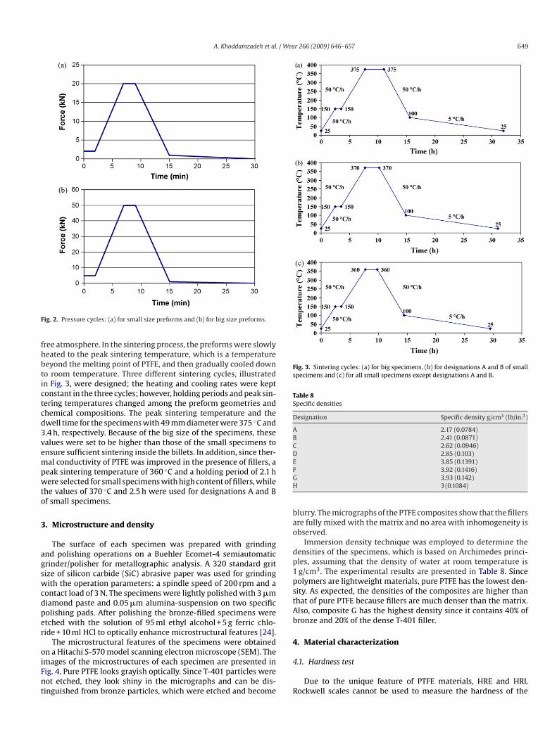
In this work, two different cylindrical chrome-plated steelmoulds with the die cross-sectional diameters of 49 mm and 31 mmwere used. The bigger mould was used to make preforms withwhich tensile test specimens were fabricated, while the smallermould was used to make the preforms for other tests such as wearand corrosion tests. The height and the thickness of both main diesare 97 mm and 7 mm, respectively. The dies thicknesses complywith the minimum die thickness requirement (provided by DuPont)assuming the yield strength of 200 MPa for steel 304. A hot mount-ing press of Struers Co. was employed. The preforming started withmould filling using a funnel to uniformly pour the powders intothe moulds, with 5 mm of the top of the mould left unfilled. Itwas conducted at a temperature of 150 ◦C for 15 min, which couldcompensate the press capacity limitation of the machine as resinparticles exhibit higher plastic flow at elevated temperatures andbecome more easily compacted and more responsive to preformpressure. Therefore, the final products preformed at elevated tem-peratures usually exhibit low void content and air-entrapment. Thepreforms were afterwards cooled down to room temperature bytap water. The preform pressure was set to be 26.52 MPa that corre-sponded to 50 kN and 20 kN preforming forces for the big and smallmoulds respectively, which was recommended by the resin sup-plier. To avoid stress-induced cracks, the maximum pressure wasapplied smoothly. 10% of the preform force was applied as initialload and held for 2 min. Then, the force was gradually increased upto the maximum preforming pressure in 5 min and held for 2 min.After that, the pressure was gradually released in 21 min and thepreforms were kept under a force of 1 kN during the cooling pro-cess. The pressure cycles for small and big preforms are presentedin Fig. 2.
2.3. Sintering process
A programmable, electrical, inert-gas Oxygon oven, wasemployed to sinter the preforms. A time interval of 2 days between
preforming and sintering was set as the aging time of the performsfor degassing and residual stress relief. The preforms were thenplaced on a perforated tray to prevent any hot spots during the sin-tering and the tray was put into the oven. On start-up, the ovenwas purged with a high flow rate of argon gas to get an oxygen-e wt.% (vol.%) Carbon fiber wt.% (vol.%) Graphite wt.% (vol.%)
0 (0) 0 (0)0 (0) 0 (0)0 (0) 0 (0)0 (0) 0 (0)
.8) 0 (0) 0 (0).9) 0 (0) 0 (0).6) 0 (0) 0 (0).4) 1 (2.1) 5.5 (10.9)
A. Khoddamzadeh et al. / Wear 266 (2009) 646–657 649
F
fhbtictcd3vempwto
3
agswcdper
oiFnt
Fig. 3. Sintering cycles: (a) for big specimens, (b) for designations A and B of smallspecimens and (c) for all small specimens except designations A and B.
Table 8Specific densities
Designation Specific density g/cm3 (lb/in.3)
A 2.17 (0.0784)B 2.41 (0.0871)C 2.62 (0.0946)D 2.85 (0.103)E 3.85 (0.1391)FGH
bao
dp1pstAb
4
ig. 2. Pressure cycles: (a) for small size preforms and (b) for big size preforms.
ree atmosphere. In the sintering process, the preforms were slowlyeated to the peak sintering temperature, which is a temperatureeyond the melting point of PTFE, and then gradually cooled downo room temperature. Three different sintering cycles, illustratedn Fig. 3, were designed; the heating and cooling rates were keptonstant in the three cycles; however, holding periods and peak sin-ering temperatures changed among the preform geometries andhemical compositions. The peak sintering temperature and thewell time for the specimens with 49 mm diameter were 375 ◦C and.4 h, respectively. Because of the big size of the specimens, thesealues were set to be higher than those of the small specimens tonsure sufficient sintering inside the billets. In addition, since ther-al conductivity of PTFE was improved in the presence of fillers, a
eak sintering temperature of 360 ◦C and a holding period of 2.1 here selected for small specimens with high content of fillers, while
he values of 370 ◦C and 2.5 h were used for designations A and Bf small specimens.
. Microstructure and density
The surface of each specimen was prepared with grindingnd polishing operations on a Buehler Ecomet-4 semiautomaticrinder/polisher for metallographic analysis. A 320 standard gritize of silicon carbide (SiC) abrasive paper was used for grindingith the operation parameters: a spindle speed of 200 rpm and a
ontact load of 3 N. The specimens were lightly polished with 3 �miamond paste and 0.05 �m alumina-suspension on two specificolishing pads. After polishing the bronze-filled specimens weretched with the solution of 95 ml ethyl alcohol + 5 g ferric chlo-ide + 10 ml HCl to optically enhance microstructural features [24].
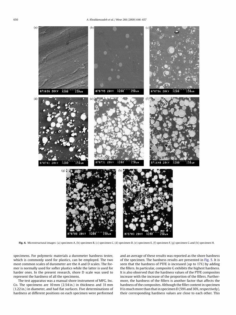
The microstructural features of the specimens were obtainedn a Hitachi S-570 model scanning electron microscope (SEM). The
mages of the microstructures of each specimen are presented inig. 4. Pure PTFE looks grayish optically. Since T-401 particles wereot etched, they look shiny in the micrographs and can be dis-inguished from bronze particles, which were etched and become4
R
3.92 (0.1416)3.93 (0.142)3 (0.1084)
lurry. The micrographs of the PTFE composites show that the fillersre fully mixed with the matrix and no area with inhomogeneity isbserved.
Immersion density technique was employed to determine theensities of the specimens, which is based on Archimedes princi-les, assuming that the density of water at room temperature isg/cm3. The experimental results are presented in Table 8. Sinceolymers are lightweight materials, pure PTFE has the lowest den-ity. As expected, the densities of the composites are higher thanhat of pure PTFE because fillers are much denser than the matrix.lso, composite G has the highest density since it contains 40% ofronze and 20% of the dense T-401 filler.
. Material characterization
.1. Hardness test
Due to the unique feature of PTFE materials, HRE and HRLockwell scales cannot be used to measure the hardness of the
650 A. Khoddamzadeh et al. / Wear 266 (2009) 646–657
Fig. 4. Microstructural images: (a) specimen A, (b) specimen B, (c) specimen C, (d) specimen D, (e) specimen E, (f) specimen F, (g) specimen G and (h) specimen H.
specimens. For polymeric materials a durometer hardness tester,which is commonly used for plastics, can be employed. The twomost common scales of durometer are the A and D scales. The for-mer is normally used for softer plastics while the latter is used forharder ones. In the present research, shore D scale was used torepresent the hardness of all the specimens.
The test apparatus was a manual shore instrument of MFG. Inc.Co. The specimens are 10 mm (2.54 in.) in thickness and 31 mm(1.22 in.) in diameter, and had flat surfaces. Five determinations ofhardness at different positions on each specimen were performed
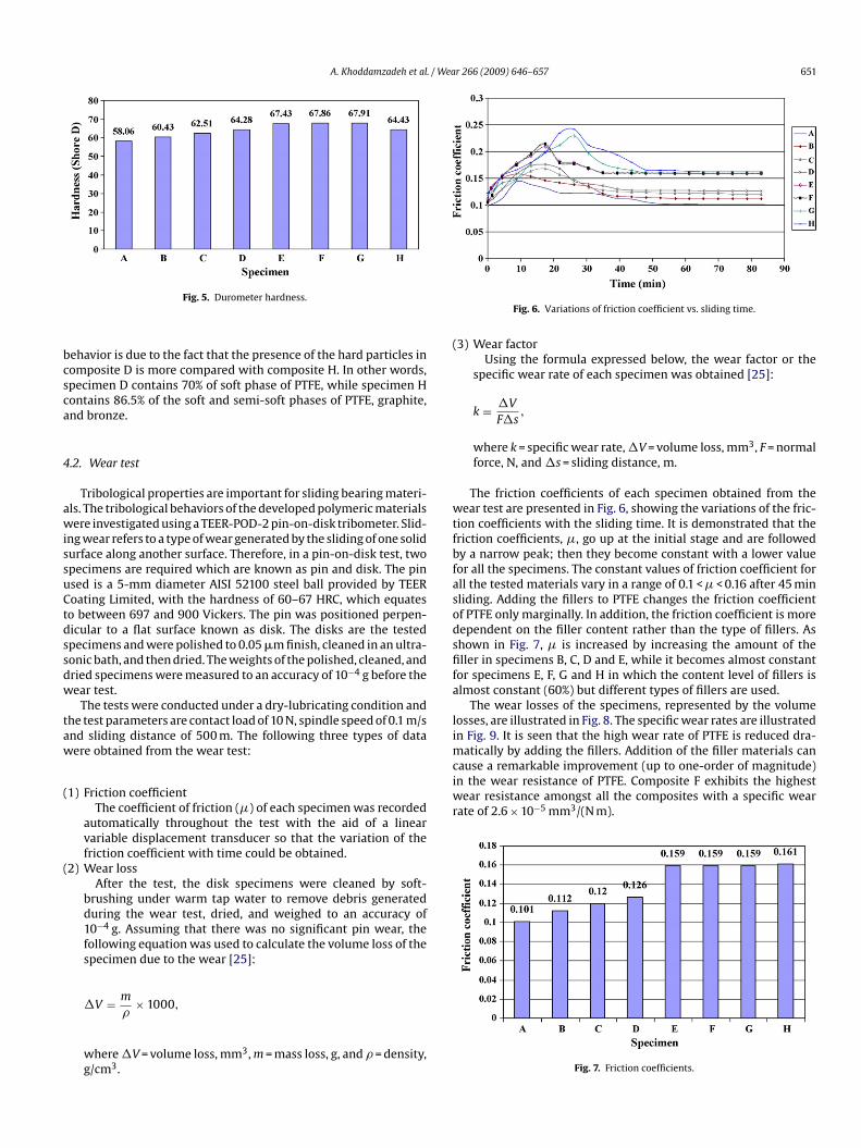
and an average of these results was reported as the shore hardnessof the specimen. The hardness results are presented in Fig. 5. It isseen that the hardness of PTFE is increased (up to 17%) by addingthe fillers. In particular, composite G exhibits the highest hardness.It is also observed that the hardness values of the PTFE compositesincrease with the increase of the proportion of the fillers. Further-more, the hardness of the fillers is another factor that affects thehardness of the composites. Although the filler content in specimenH is much more than that in specimen D (59% and 30%, respectively),their corresponding hardness values are close to each other. This
A. Khoddamzadeh et al. / Wear 266 (2009) 646–657 651
bcsca
4
awissuCtdssdw
taw
(
(
(
wtfbfasodsfifa
limatically by adding the fillers. Addition of the filler materials cancause a remarkable improvement (up to one-order of magnitude)in the wear resistance of PTFE. Composite F exhibits the highestwear resistance amongst all the composites with a specific wearrate of 2.6 × 10⁻⁵ mm3/(N m).
Fig. 5. Durometer hardness.
ehavior is due to the fact that the presence of the hard particles inomposite D is more compared with composite H. In other words,pecimen D contains 70% of soft phase of PTFE, while specimen Hontains 86.5% of the soft and semi-soft phases of PTFE, graphite,nd bronze.
.2. Wear test
Tribological properties are important for sliding bearing materi-ls. The tribological behaviors of the developed polymeric materialsere investigated using a TEER-POD-2 pin-on-disk tribometer. Slid-
ng wear refers to a type of wear generated by the sliding of one solidurface along another surface. Therefore, in a pin-on-disk test, twopecimens are required which are known as pin and disk. The pinsed is a 5-mm diameter AISI 52100 steel ball provided by TEERoating Limited, with the hardness of 60–67 HRC, which equateso between 697 and 900 Vickers. The pin was positioned perpen-icular to a flat surface known as disk. The disks are the testedpecimens and were polished to 0.05 �m finish, cleaned in an ultra-onic bath, and then dried. The weights of the polished, cleaned, andried specimens were measured to an accuracy of 10−4 g before theear test.
The tests were conducted under a dry-lubricating condition andhe test parameters are contact load of 10 N, spindle speed of 0.1 m/snd sliding distance of 500 m. The following three types of dataere obtained from the wear test:
1) Friction coefficientThe coefficient of friction (�) of each specimen was recorded
automatically throughout the test with the aid of a linearvariable displacement transducer so that the variation of thefriction coefficient with time could be obtained.
2) Wear lossAfter the test, the disk specimens were cleaned by soft-
brushing under warm tap water to remove debris generatedduring the wear test, dried, and weighed to an accuracy of10−4 g. Assuming that there was no significant pin wear, thefollowing equation was used to calculate the volume loss of the
specimen due to the wear [25]:�V = m
�× 1000,
where �V = volume loss, mm3, m = mass loss, g, and � = density,g/cm3.
Fig. 6. Variations of friction coefficient vs. sliding time.
3) Wear factorUsing the formula expressed below, the wear factor or the
specific wear rate of each specimen was obtained [25]:
k = �V
F�s,
where k = specific wear rate, �V = volume loss, mm3, F = normalforce, N, and �s = sliding distance, m.
The friction coefficients of each specimen obtained from theear test are presented in Fig. 6, showing the variations of the fric-
ion coefficients with the sliding time. It is demonstrated that theriction coefficients, �, go up at the initial stage and are followedy a narrow peak; then they become constant with a lower valueor all the specimens. The constant values of friction coefficient forll the tested materials vary in a range of 0.1 < � < 0.16 after 45 minliding. Adding the fillers to PTFE changes the friction coefficientf PTFE only marginally. In addition, the friction coefficient is moreependent on the filler content rather than the type of fillers. Ashown in Fig. 7, � is increased by increasing the amount of theller in specimens B, C, D and E, while it becomes almost constant
or specimens E, F, G and H in which the content level of fillers islmost constant (60%) but different types of fillers are used.
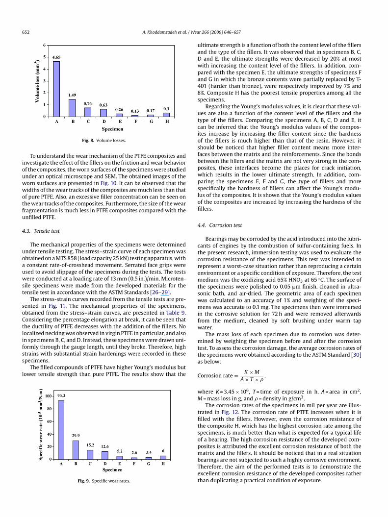
The wear losses of the specimens, represented by the volumeosses, are illustrated in Fig. 8. The specific wear rates are illustratedn Fig. 9. It is seen that the high wear rate of PTFE is reduced dra-
Fig. 7. Friction coefficients.
652 A. Khoddamzadeh et al. / We
iouwwotfu
4
uoauwst
soCtlifss
l
Fig. 8. Volume losses.
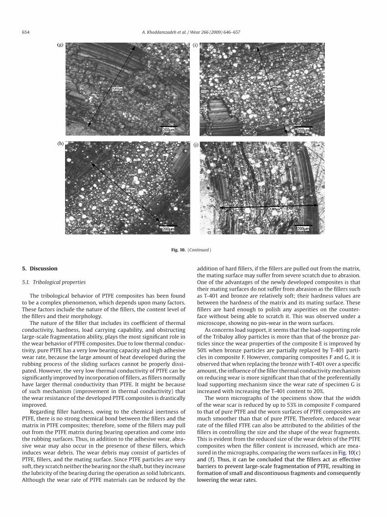
To understand the wear mechanism of the PTFE composites andnvestigate the effect of the fillers on the friction and wear behaviorf the composites, the worn surfaces of the specimens were studiednder an optical microscope and SEM. The obtained images of theorn surfaces are presented in Fig. 10. It can be observed that theidths of the wear tracks of the composites are much less than that
f pure PTFE. Also, an excessive filler concentration can be seen onhe wear tracks of the composites. Furthermore, the size of the wearragmentation is much less in PTFE composites compared with thenfilled PTFE.
.3. Tensile test
The mechanical properties of the specimens were determinednder tensile testing. The stress–strain curve of each specimen wasbtained on a MTS 858 (load capacity 25 kN) testing apparatus, withconstant rate-of-crosshead movement. Serrated face grips weresed to avoid slippage of the specimens during the tests. The testsere conducted at a loading rate of 13 mm (0.5 in.)/min. Microten-
ile specimens were made from the developed materials for theensile test in accordance with the ASTM Standards [26–29].
The stress-strain curves recorded from the tensile tests are pre-ented in Fig. 11. The mechanical properties of the specimens,btained from the stress–strain curves, are presented in Table 9.onsidering the percentage elongation at break, it can be seen thathe ductility of PTFE decreases with the addition of the fillers. Noocalized necking was observed in virgin PTFE in particular, and alson specimens B, C, and D. Instead, these specimens were drawn uni-
ormly through the gauge length, until they broke. Therefore, hightrains with substantial strain hardenings were recorded in thesepecimens.The filled compounds of PTFE have higher Young’s modulus butower tensile strength than pure PTFE. The results show that the
Fig. 9. Specific wear rates.
ar 266 (2009) 646–657
ultimate strength is a function of both the content level of the fillersand the type of the fillers. It was observed that in specimens B, C,D and E, the ultimate strengths were decreased by 20% at mostwith increasing the content level of the fillers. In addition, com-pared with the specimen E, the ultimate strengths of specimens Fand G in which the bronze contents were partially replaced by T-401 (harder than bronze), were respectively improved by 7% and8%. Composite H has the poorest tensile properties among all thespecimens.
Regarding the Young’s modulus values, it is clear that these val-ues are also a function of the content level of the fillers and thetype of the fillers. Comparing the specimens A, B, C, D and E, itcan be inferred that the Young’s modulus values of the compos-ites increase by increasing the filler content since the hardnessof the fillers is much higher than that of the resin. However, itshould be noticed that higher filler content means more inter-faces between the matrix and the reinforcements. Since the bondsbetween the fillers and the matrix are not very strong in the com-posites, these interfaces become the places for crack initiation,which results in the lower ultimate strength. In addition, com-paring the specimens E, F and G, the type of fillers and morespecifically the hardness of fillers can affect the Young’s modu-lus of the composites. It is shown that the Young’s modulus valuesof the composites are increased by increasing the hardness of thefillers.
4.4. Corrosion test
Bearings may be corroded by the acid introduced into the lubri-cants of engines by the combustion of sulfur-containing fuels. Inthe present research, immersion testing was used to evaluate thecorrosion resistance of the specimens. This test was intended torepresent a worst-case situation rather than reproducing a certainenvironment or a specific condition of exposure. Therefore, the testmedium was the oxidizing acid 65% HNO3 at 65 ◦C. The surface ofthe specimens were polished to 0.05 �m finish, cleaned in ultra-sonic bath, and air-dried. The geometric area of each specimenwas calculated to an accuracy of 1% and weighing of the speci-mens was accurate to 0.1 mg. The specimens then were immersedin the corrosive solution for 72 h and were removed afterwardsfrom the medium, cleaned by soft brushing under warm tapwater.
The mass loss of each specimen due to corrosion was deter-mined by weighing the specimen before and after the corrosiontest. To assess the corrosion damage, the average corrosion rates ofthe specimens were obtained according to the ASTM Standard [30]as below:
Corrosion rate = K × M
A × T × �,
where K = 3.45 × 10⁶, T = time of exposure in h, A = area in cm2,M = mass loss in g, and � = density in g/cm3.
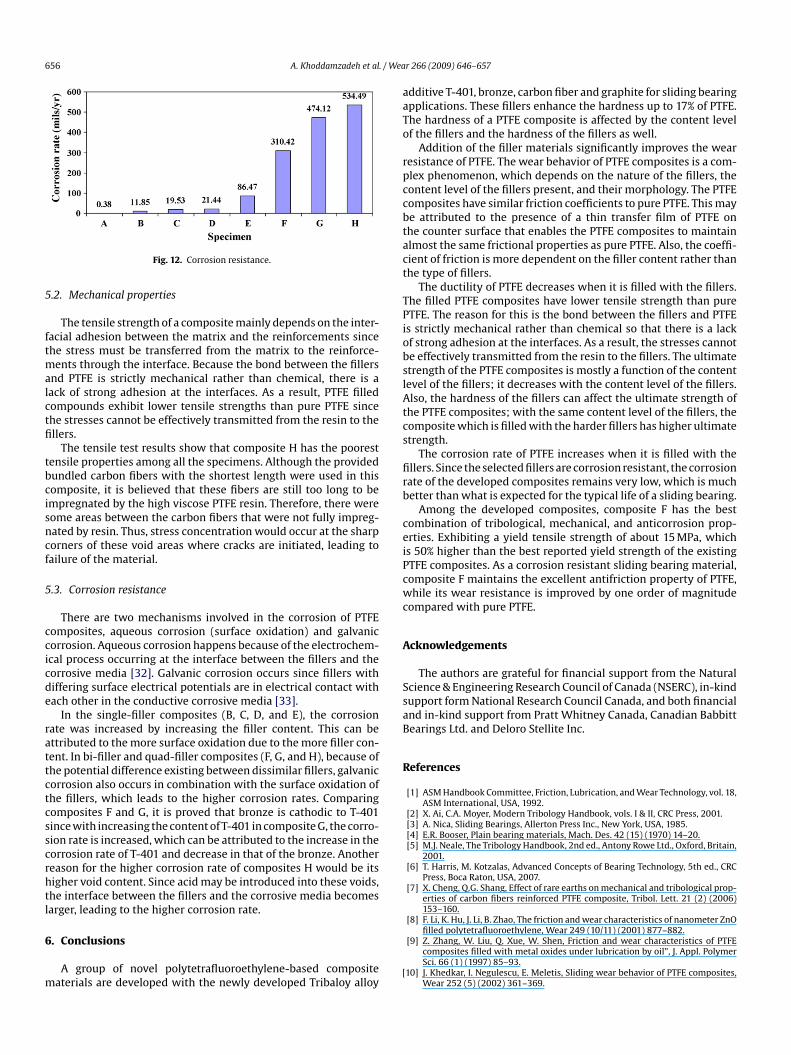
The corrosion rates of the specimens in mil per year are illus-trated in Fig. 12. The corrosion rate of PTFE increases when it isfilled with the fillers. However, even the corrosion resistance ofthe composite H, which has the highest corrosion rate among thespecimens, is much better than what is expected for a typical lifeof a bearing. The high corrosion resistance of the developed com-posites is attributed the excellent corrosion resistance of both thematrix and the fillers. It should be noticed that in a real situation
bearings are not subjected to such a highly corrosive environment.Therefore, the aim of the performed tests is to demonstrate theexcellent corrosion resistance of the developed composites ratherthan duplicating a practical condition of exposure.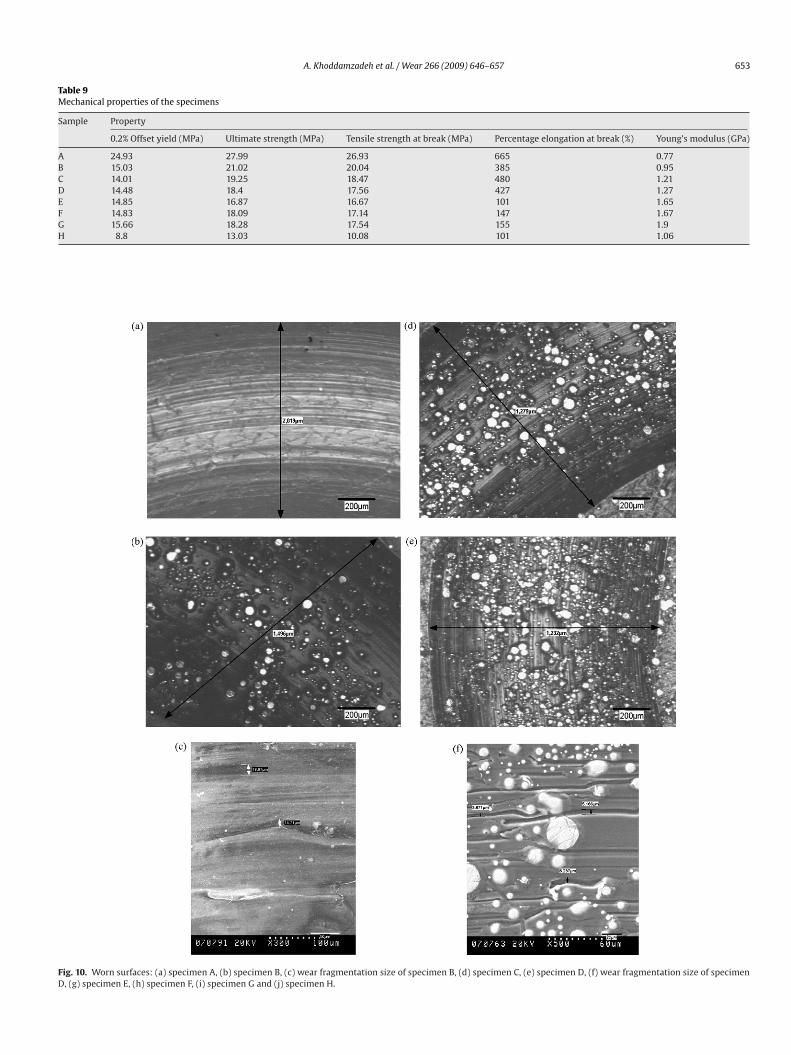
A. Khoddamzadeh et al. / Wear 266 (2009) 646–657 653
Table 9Mechanical properties of the specimens
Sample Property
0.2% Offset yield (MPa) Ultimate strength (MPa) Tensile strength at break (MPa) Percentage elongation at break (%) Young’s modulus (GPa)
A 24.93 27.99 26.93 665 0.77B 15.03 21.02 20.04 385 0.95C 14.01 19.25 18.47 480 1.21D 14.48 18.4 17.56 427 1.27E 14.85 16.87 16.67 101 1.65F 14.83 18.09 17.14 147 1.67G 15.66 18.28 17.54 155 1.9H 8.8 13.03 10.08 101 1.06
Fig. 10. Worn surfaces: (a) specimen A, (b) specimen B, (c) wear fragmentation size of specimen B, (d) specimen C, (e) specimen D, (f) wear fragmentation size of specimenD, (g) specimen E, (h) specimen F, (i) specimen G and (j) specimen H.
654 A. Khoddamzadeh et al. / Wear 266 (2009) 646–657
(Con
Fig. 10.5. Discussion
5.1. Tribological properties
The tribological behavior of PTFE composites has been foundto be a complex phenomenon, which depends upon many factors.These factors include the nature of the fillers, the content level ofthe fillers and their morphology.
The nature of the filler that includes its coefficient of thermalconductivity, hardness, load carrying capability, and obstructinglarge-scale fragmentation ability, plays the most significant role inthe wear behavior of PTFE composites. Due to low thermal conduc-tivity, pure PTFE has a very low bearing capacity and high adhesivewear rate, because the large amount of heat developed during therubbing process of the sliding surfaces cannot be properly dissi-pated. However, the very low thermal conductivity of PTFE can besignificantly improved by incorporation of fillers, as fillers normallyhave larger thermal conductivity than PTFE. It might be becauseof such mechanism (improvement in thermal conductivity) thatthe wear resistance of the developed PTFE composites is drasticallyimproved.
Regarding filler hardness, owing to the chemical inertness ofPTFE, there is no strong chemical bond between the fillers and thematrix in PTFE composites; therefore, some of the fillers may pullout from the PTFE matrix during bearing operation and come intothe rubbing surfaces. Thus, in addition to the adhesive wear, abra-sive wear may also occur in the presence of these fillers, whichinduces wear debris. The wear debris may consist of particles of
PTFE, fillers, and the mating surface. Since PTFE particles are verysoft, they scratch neither the bearing nor the shaft, but they increasethe lubricity of the bearing during the operation as solid lubricants.Although the wear rate of PTFE materials can be reduced by thetinued )
addition of hard fillers, if the fillers are pulled out from the matrix,the mating surface may suffer from severe scratch due to abrasion.One of the advantages of the newly developed composites is thattheir mating surfaces do not suffer from abrasion as the fillers suchas T-401 and bronze are relatively soft; their hardness values arebetween the hardness of the matrix and its mating surface. Thesefillers are hard enough to polish any asperities on the counter-face without being able to scratch it. This was observed under amicroscope, showing no pin-wear in the worn surfaces.
As concerns load support, it seems that the load-supporting roleof the Tribaloy alloy particles is more than that of the bronze par-ticles since the wear properties of the composite E is improved by50% when bronze particles are partially replaced by T-401 parti-cles in composite F. However, comparing composites F and G, it isobserved that when replacing the bronze with T-401 over a specificamount, the influence of the filler thermal conductivity mechanismon reducing wear is more significant than that of the preferentiallyload supporting mechanism since the wear rate of specimen G isincreased with increasing the T-401 content to 20%.
The worn micrographs of the specimens show that the widthof the wear scar is reduced by up to 53% in composite F comparedto that of pure PTFE and the worn surfaces of PTFE composites aremuch smoother than that of pure PTFE. Therefore, reduced wearrate of the filled FTFE can also be attributed to the abilities of thefillers in controlling the size and the shape of the wear fragments.This is evident from the reduced size of the wear debris of the PTFEcomposites when the filler content is increased, which are mea-sured in the micrographs, comparing the worn surfaces in Fig. 10(c)
and (f). Thus, it can be concluded that the fillers act as effectivebarriers to prevent large-scale fragmentation of PTFE, resulting information of small and discontinuous fragments and consequentlylowering the wear rates.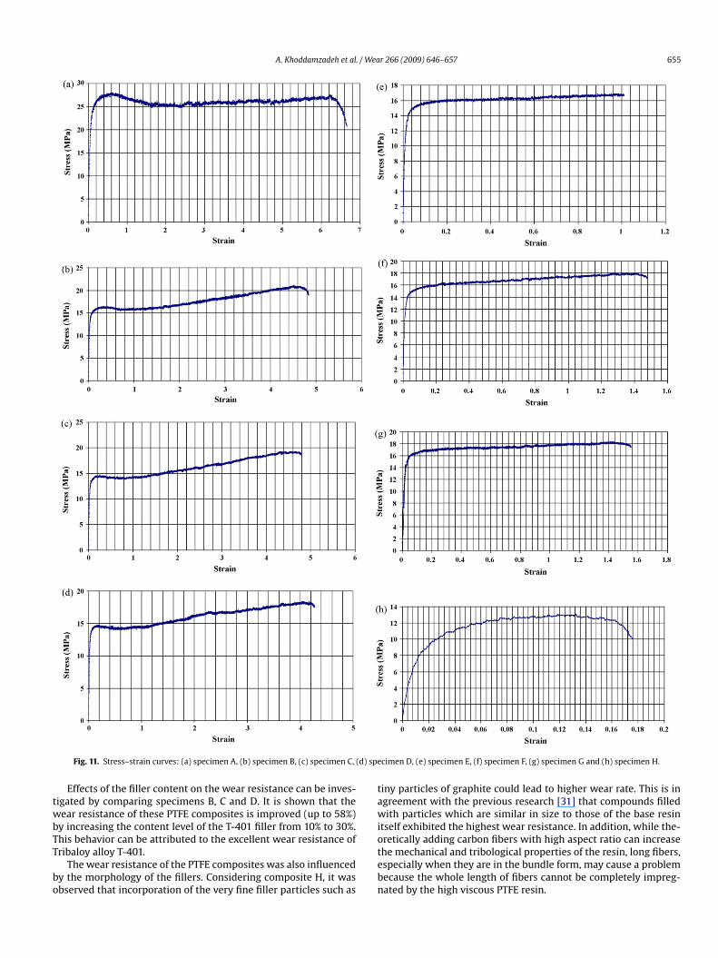
A. Khoddamzadeh et al. / Wear 266 (2009) 646–657 655
Fig. 11. Stress–strain curves: (a) specimen A, (b) specimen B, (c) specimen C, (d) specimen D, (e) specimen E, (f) specimen F, (g) specimen G and (h) specimen H.
Effects of the filler content on the wear resistance can be inves-tigated by comparing specimens B, C and D. It is shown that thewear resistance of these PTFE composites is improved (up to 58%)by increasing the content level of the T-401 filler from 10% to 30%.This behavior can be attributed to the excellent wear resistance ofTribaloy alloy T-401.
The wear resistance of the PTFE composites was also influencedby the morphology of the fillers. Considering composite H, it wasobserved that incorporation of the very fine filler particles such as
tiny particles of graphite could lead to higher wear rate. This is inagreement with the previous research [31] that compounds filledwith particles which are similar in size to those of the base resinitself exhibited the highest wear resistance. In addition, while the-oretically adding carbon fibers with high aspect ratio can increasethe mechanical and tribological properties of the resin, long fibers,especially when they are in the bundle form, may cause a problembecause the whole length of fibers cannot be completely impreg-nated by the high viscous PTFE resin.
656 A. Khoddamzadeh et al. / Wea
5
ftmalctfi
tbcisncf
5
ccicde
rattctcsscrhtl
6
m
aaTo
rpccbtact
TPiobslAtcs
firb
ceiPcwc
A
SsaB
R
Fig. 12. Corrosion resistance.
.2. Mechanical properties
The tensile strength of a composite mainly depends on the inter-acial adhesion between the matrix and the reinforcements sincehe stress must be transferred from the matrix to the reinforce-
ents through the interface. Because the bond between the fillersnd PTFE is strictly mechanical rather than chemical, there is aack of strong adhesion at the interfaces. As a result, PTFE filledompounds exhibit lower tensile strengths than pure PTFE sincehe stresses cannot be effectively transmitted from the resin to thellers.
The tensile test results show that composite H has the poorestensile properties among all the specimens. Although the providedundled carbon fibers with the shortest length were used in thisomposite, it is believed that these fibers are still too long to bempregnated by the high viscose PTFE resin. Therefore, there wereome areas between the carbon fibers that were not fully impreg-ated by resin. Thus, stress concentration would occur at the sharporners of these void areas where cracks are initiated, leading toailure of the material.
.3. Corrosion resistance
There are two mechanisms involved in the corrosion of PTFEomposites, aqueous corrosion (surface oxidation) and galvanicorrosion. Aqueous corrosion happens because of the electrochem-cal process occurring at the interface between the fillers and theorrosive media [32]. Galvanic corrosion occurs since fillers withiffering surface electrical potentials are in electrical contact withach other in the conductive corrosive media [33].
In the single-filler composites (B, C, D, and E), the corrosionate was increased by increasing the filler content. This can bettributed to the more surface oxidation due to the more filler con-ent. In bi-filler and quad-filler composites (F, G, and H), because ofhe potential difference existing between dissimilar fillers, galvanicorrosion also occurs in combination with the surface oxidation ofhe fillers, which leads to the higher corrosion rates. Comparingomposites F and G, it is proved that bronze is cathodic to T-401ince with increasing the content of T-401 in composite G, the corro-ion rate is increased, which can be attributed to the increase in theorrosion rate of T-401 and decrease in that of the bronze. Anothereason for the higher corrosion rate of composites H would be itsigher void content. Since acid may be introduced into these voids,he interface between the fillers and the corrosive media becomesarger, leading to the higher corrosion rate.
. Conclusions
A group of novel polytetrafluoroethylene-based compositeaterials are developed with the newly developed Tribaloy alloy
[
r 266 (2009) 646–657
dditive T-401, bronze, carbon fiber and graphite for sliding bearingpplications. These fillers enhance the hardness up to 17% of PTFE.he hardness of a PTFE composite is affected by the content levelf the fillers and the hardness of the fillers as well.
Addition of the filler materials significantly improves the wearesistance of PTFE. The wear behavior of PTFE composites is a com-lex phenomenon, which depends on the nature of the fillers, theontent level of the fillers present, and their morphology. The PTFEomposites have similar friction coefficients to pure PTFE. This maye attributed to the presence of a thin transfer film of PTFE onhe counter surface that enables the PTFE composites to maintainlmost the same frictional properties as pure PTFE. Also, the coeffi-ient of friction is more dependent on the filler content rather thanhe type of fillers.
The ductility of PTFE decreases when it is filled with the fillers.he filled PTFE composites have lower tensile strength than pureTFE. The reason for this is the bond between the fillers and PTFEs strictly mechanical rather than chemical so that there is a lackf strong adhesion at the interfaces. As a result, the stresses cannote effectively transmitted from the resin to the fillers. The ultimatetrength of the PTFE composites is mostly a function of the contentevel of the fillers; it decreases with the content level of the fillers.lso, the hardness of the fillers can affect the ultimate strength of
he PTFE composites; with the same content level of the fillers, theomposite which is filled with the harder fillers has higher ultimatetrength.
The corrosion rate of PTFE increases when it is filled with thellers. Since the selected fillers are corrosion resistant, the corrosionate of the developed composites remains very low, which is muchetter than what is expected for the typical life of a sliding bearing.
Among the developed composites, composite F has the bestombination of tribological, mechanical, and anticorrosion prop-rties. Exhibiting a yield tensile strength of about 15 MPa, whichs 50% higher than the best reported yield strength of the existingTFE composites. As a corrosion resistant sliding bearing material,omposite F maintains the excellent antifriction property of PTFE,hile its wear resistance is improved by one order of magnitude
ompared with pure PTFE.
cknowledgements
The authors are grateful for financial support from the Naturalcience & Engineering Research Council of Canada (NSERC), in-kindupport form National Research Council Canada, and both financialnd in-kind support from Pratt Whitney Canada, Canadian Babbittearings Ltd. and Deloro Stellite Inc.
eferences
[1] ASM Handbook Committee, Friction, Lubrication, and Wear Technology, vol. 18,ASM International, USA, 1992.
[2] X. Ai, C.A. Moyer, Modern Tribology Handbook, vols. I & II, CRC Press, 2001.[3] A. Nica, Sliding Bearings, Allerton Press Inc., New York, USA, 1985.[4] E.R. Booser, Plain bearing materials, Mach. Des. 42 (15) (1970) 14–20.[5] M.J. Neale, The Tribology Handbook, 2nd ed., Antony Rowe Ltd., Oxford, Britain,
2001.[6] T. Harris, M. Kotzalas, Advanced Concepts of Bearing Technology, 5th ed., CRC
Press, Boca Raton, USA, 2007.[7] X. Cheng, Q.G. Shang, Effect of rare earths on mechanical and tribological prop-
erties of carbon fibers reinforced PTFE composite, Tribol. Lett. 21 (2) (2006)153–160.
[8] F. Li, K. Hu, J. Li, B. Zhao, The friction and wear characteristics of nanometer ZnO
filled polytetrafluoroethylene, Wear 249 (10/11) (2001) 877–882.[9] Z. Zhang, W. Liu, Q. Xue, W. Shen, Friction and wear characteristics of PTFEcomposites filled with metal oxides under lubrication by oil”, J. Appl. PolymerSci. 66 (1) (1997) 85–93.
10] J. Khedkar, I. Negulescu, E. Meletis, Sliding wear behavior of PTFE composites,Wear 252 (5) (2002) 361–369.
/ We
[31] T. Blanchet, F. Kennedy, Sliding wear mechanism of polytetrafluoroethylene
A. Khoddamzadeh et al.
[11] C. Speerschneider, C. Li, The role of filler geometrical shape in wear and frictionof filled PTFE, Wear 5 (1962) 392–399.
[12] B.J. Briscoe, M.D. Steward, The effect of carbon aspect ratio on the friction andwear of PTFE, Wear 42 (1) (1977) 99–107.
[13] K. Tanaka, S. Kawakami, Effect of various fillers on the friction and wear ofpolytetrafluoroethylene-based composites, Wear 79 (2) (1982) 221–234.
[14] J.R. Davis, Nickel, Cobalt, and Their Alloys, ASM International, Materials Park,2000.
[15] W. Betteridge, Cobalt and Its Alloys, Halsted Press, Chichester, 1982.[16] A. Halstead, R.D. Rawlings, Structure and hardness of Co–Mo–Cr–Si wear resis-
tant alloys (Tribaloys), Met. Sci. 18 (10) (1984) 491–500.[17] C.B. Cameron, D.P. Ferriss, Tribaloy intermetallic materials: new wear- and
corrosion-resistant alloys, Anti-Corr. Methods Mater. 22 (4) (1975) 5–8.[18] R.D. Schmidt, D.P. Ferriss, New materials resistant to wear and corrosion to
1000 ◦C, Wear 32 (3) (1975) 279–289.[19] A. Halstead, R.D. Rawlings, The effect of iron additions on the microstructure
and properties of the Tribaloy Co–Mo–Cr–Si wear resistant alloys, J. Mater. Sci.20 (5) (1985) 1693–1704.
[20] R. Liu, W. Xu, M.X. Yao, P.C. Patnaik, X.J. Wu, A newly developed Tribaloy alloywith increased ductility, Scripta Mater. 53 (12) (2005) 1351–1355.
[21] W. Xu, R. Liu, P.C. Patnaik, M.X. Yao, X.J. Wu, Mechanical and tribological prop-erties of newly developed Tribaloy alloys, Mater. Sci. Eng. A 452–453 (2007)427–436.
[22] R. Liu, M.X. Yao, P.C. Patnaik, X.J. Wu, Investigation of mechanical behaviorof cobalt-based intermetallic materials using a nano-indentation technique,J. Adv. Mater. Special Edition No. 2 (2007) 65–75.
ar 266 (2009) 646–657 657
[23] X. Yao, J.B.C. Wu, W. Xu, R. Liu, Microstructural characteristics and corrosionresistance in molten Zn–Al bath of Co–Mo–Cr–Si alloys, Mater. Sci. Eng. A 407(1/2) (2005) 299–305.
[24] ASM Handbook Committee, Metallography and Microstructures, vol. 9, ASMInternational, USA, 2004.
[25] ASTM Standard Committee, G 99-05, Standard Test Method for Wear Testingwith a Pin-on-Disk Apparatus, ASTM International, USA, 2005.
[26] ASTM Standard Committee, D 4894-04, Standard Specification for PTFE Gran-ular Molding and Ram Extrusion Materials, ASTM International, USA, 2004.
[27] ASTM Standard Committee, D 4745-06, Standard Specification for Filled Com-pounds of PTFE Molding and Extrusion Materials, ASTM International, USA,2007.
[28] ASTM Standard Committee, D 1708-06a, Standard Test Method for Tensile Prop-erties of Plastics by Use of Microtensile Specimens, ASTM International, USA,2006.
[29] ASTM Standard Committee, D 638M-93, Standard Test Method for Tensile Prop-erties of Plastics (Metric), ASTM International, USA, 1993.
[30] ASTM Standard Committee, G 1-03, Standard Practice for Preparing, Cleaning,and Evaluating Corrosion Test Specimens, ASTM International, USA, 2007.
(PTFE) and PTFE composites, Wear 153 (1) (1992) 229–243.[32] ASM Handbook Committee, Corrosion: Fundamentals, Testing and Protection,
vol. 13A, ASM International, USA, 2003.[33] ASM Handbook Committee, Corrosion: Materials, ASM International, vol. 13B,
USA, 2005.
Related Documents