Novel expert system for defining power quality compensators Eduardo Verri Liberado a,⇑ , Fernando Pinhabel Marafão b , Marcelo Godoy Simões c , Wesley Angelino de Souza a , José Antenor Pomilio a a University of Campinas (UNICAMP), School of Electrical and Computer Engineering (FEEC), Department of Systems and Energy (DSE), Av. Albert Einstein, 400, 13083-852 Campinas, SP, Brazil b Univ Estadual Paulista (UNESP), Campus of Sorocaba, Group of Automation and Integrated Systems (GASI), Av. Três de Março, 511, 18087-180 Sorocaba, SP, Brazil c Colorado School of Mines, Department of Electrical Engineering and Computer Science, 80401 Golden, CO, United States article info Article history: Available online 27 December 2014 Keywords: Compensation Decision-maker Expert system Harmonic distortion Load unbalance Power factor correction Power quality abstract In order to ensure good power quality for modern power systems and/or industrial installations, power conditioning devices have been extensively applied. However, the data analysis for the installation of a determined compensator mainly considers a particular power quality index or disturbance and it is usually based on human expertise. Therefore, this paper proposes a novel expert system that automati- cally suggests the most appropriate and cost-effective solution for compensating reactive, harmonic and unbalanced current through a careful analysis of several power quality indices and some grid character- istics. Such an expert system is an important tool in real-world applications, where there is a complex scenario in choosing, designing and applying power quality compensators in modern power grids. Since there are no strict boundaries for voltage and current non idealities at distribution level or clear correlation between them and possible solutions, a fuzzy decision-maker was developed to deal with such uncertainties and to embed human expertise in the system. The approach is based on analyzing data from a given time window and providing off-line recommendations for the design and installation of proper compensators. Therefore, the application of the proposed expert system may result in enhanced and faster projects when compared to the traditional design methods for power conditioning. A computational study consisting on applying the suggested compensators for a 5-node network and different load configurations shows the effectiveness of the proposed expert system. Ó 2014 Elsevier Ltd. All rights reserved. 1. Introduction In terms of industrial applications, power conditioning devices may ensure good power quality (PQ) at a certain point of common coupling (PCC). This consists in avoiding that particular load char- acteristic, such as unbalanced connection, reactive power and non linearities (which cause harmonic distortion) affect the grid. Con- sequently, the installation of a compensator may increase the net- work efficiency, reduce costs and avoid consumer’s penalizations by low power factor (Akagi, Watanabe, & Aredes, 2007; Bollen, 2003; Singh, Al-Haddad, & Chandra, 1999). Even though many traditional compensators (such as capacitor banks for power factor correction) are still used and might be cost- effective, there are an increasing number of restrictions for their application, mainly due to high levels of voltage distortion in the grid (Bisanovic, Hajro, & Samardzic, 2014; Jintakosonwit, Srianthumrong, & Jintagosonwit, 2007). In this case, the compensa- tors may cause more problems than tangible benefits (Currence, Plizga, & Nelson, 1995; Obulesu, Reddy, & Kusumalatha, 2014; Phipps, Nelson, & Sen, 1994). Therefore, during the design stage of a compensation system, it is important to consider several PQ indices, observing its recom- mended limits (when available), in order to determine the feasibil- ity of such solution. Nevertheless, the main problems to proceed in this way are: the absence of PQ indices in standard power meters (usual frontier equipment between industries and utilities) and/or contradictory results for a PQ index when calculated by different power meters (Galvão, Belchior, Silveira, & Ribeiro, 2014); the lack of strict boundaries for all voltage and current non idealities at distribution level and specially, the absence of clear relationship among them and possible solutions; and finally, the lack of expertise on the application of power conditioners by young practical engineers. Regarding the PQ monitoring, the current literature has leading to new trends in electrical grids, mostly related to the concept of http://dx.doi.org/10.1016/j.eswa.2014.12.032 0957-4174/Ó 2014 Elsevier Ltd. All rights reserved. ⇑ Corresponding author. Tel.: +55 15 98118 3886. E-mail addresses: [email protected] (E.V. Liberado), fmarafao@ sorocaba.unesp.br (F.P. Marafão), [email protected] (M.G. Simões), wesley@fc. unesp.br (W.A.d. Souza), [email protected] (J.A. Pomilio). Expert Systems with Applications 42 (2015) 3562–3570 Contents lists available at ScienceDirect Expert Systems with Applications journal homepage: www.elsevier.com/locate/eswa

Welcome message from author
This document is posted to help you gain knowledge. Please leave a comment to let me know what you think about it! Share it to your friends and learn new things together.
Transcript
Expert Systems with Applications 42 (2015) 3562–3570
Contents lists available at ScienceDirect
Expert Systems with Applications
journal homepage: www.elsevier .com/locate /eswa
Novel expert system for defining power quality compensators
http://dx.doi.org/10.1016/j.eswa.2014.12.0320957-4174/� 2014 Elsevier Ltd. All rights reserved.
⇑ Corresponding author. Tel.: +55 15 98118 3886.E-mail addresses: [email protected] (E.V. Liberado), fmarafao@
sorocaba.unesp.br (F.P. Marafão), [email protected] (M.G. Simões), [email protected] (W.A.d. Souza), [email protected] (J.A. Pomilio).
Eduardo Verri Liberado a,⇑, Fernando Pinhabel Marafão b, Marcelo Godoy Simões c,Wesley Angelino de Souza a, José Antenor Pomilio a
a University of Campinas (UNICAMP), School of Electrical and Computer Engineering (FEEC), Department of Systems and Energy (DSE), Av. Albert Einstein,400, 13083-852 Campinas, SP, Brazilb Univ Estadual Paulista (UNESP), Campus of Sorocaba, Group of Automation and Integrated Systems (GASI), Av. Três de Março, 511, 18087-180 Sorocaba, SP, Brazilc Colorado School of Mines, Department of Electrical Engineering and Computer Science, 80401 Golden, CO, United States
a r t i c l e i n f o
Article history:Available online 27 December 2014
Keywords:CompensationDecision-makerExpert systemHarmonic distortionLoad unbalancePower factor correctionPower quality
a b s t r a c t
In order to ensure good power quality for modern power systems and/or industrial installations, powerconditioning devices have been extensively applied. However, the data analysis for the installation of adetermined compensator mainly considers a particular power quality index or disturbance and it isusually based on human expertise. Therefore, this paper proposes a novel expert system that automati-cally suggests the most appropriate and cost-effective solution for compensating reactive, harmonic andunbalanced current through a careful analysis of several power quality indices and some grid character-istics. Such an expert system is an important tool in real-world applications, where there is a complexscenario in choosing, designing and applying power quality compensators in modern power grids. Sincethere are no strict boundaries for voltage and current non idealities at distribution level or clearcorrelation between them and possible solutions, a fuzzy decision-maker was developed to deal withsuch uncertainties and to embed human expertise in the system. The approach is based on analyzing datafrom a given time window and providing off-line recommendations for the design and installation ofproper compensators. Therefore, the application of the proposed expert system may result in enhancedand faster projects when compared to the traditional design methods for power conditioning. Acomputational study consisting on applying the suggested compensators for a 5-node network anddifferent load configurations shows the effectiveness of the proposed expert system.
� 2014 Elsevier Ltd. All rights reserved.
1. Introduction
In terms of industrial applications, power conditioning devicesmay ensure good power quality (PQ) at a certain point of commoncoupling (PCC). This consists in avoiding that particular load char-acteristic, such as unbalanced connection, reactive power and nonlinearities (which cause harmonic distortion) affect the grid. Con-sequently, the installation of a compensator may increase the net-work efficiency, reduce costs and avoid consumer’s penalizationsby low power factor (Akagi, Watanabe, & Aredes, 2007; Bollen,2003; Singh, Al-Haddad, & Chandra, 1999).
Even though many traditional compensators (such as capacitorbanks for power factor correction) are still used and might be cost-effective, there are an increasing number of restrictions for theirapplication, mainly due to high levels of voltage distortion in the
grid (Bisanovic, Hajro, & Samardzic, 2014; Jintakosonwit,Srianthumrong, & Jintagosonwit, 2007). In this case, the compensa-tors may cause more problems than tangible benefits (Currence,Plizga, & Nelson, 1995; Obulesu, Reddy, & Kusumalatha, 2014;Phipps, Nelson, & Sen, 1994).
Therefore, during the design stage of a compensation system, itis important to consider several PQ indices, observing its recom-mended limits (when available), in order to determine the feasibil-ity of such solution.
Nevertheless, the main problems to proceed in this way are: theabsence of PQ indices in standard power meters (usual frontierequipment between industries and utilities) and/or contradictoryresults for a PQ index when calculated by different power meters(Galvão, Belchior, Silveira, & Ribeiro, 2014); the lack of strictboundaries for all voltage and current non idealities at distributionlevel and specially, the absence of clear relationship among themand possible solutions; and finally, the lack of expertise on theapplication of power conditioners by young practical engineers.
Regarding the PQ monitoring, the current literature has leadingto new trends in electrical grids, mostly related to the concept of
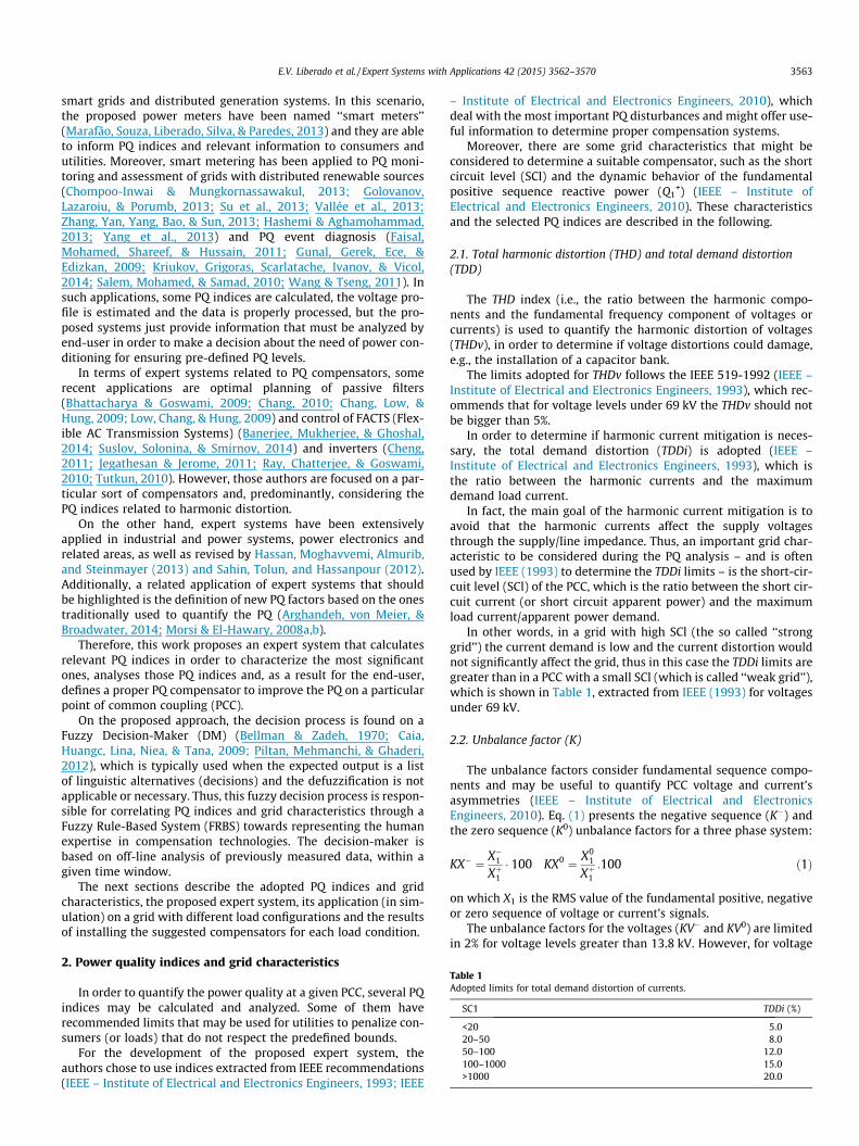
Table 1Adopted limits for total demand distortion of currents.
SC1 TDDi (%)
<20 5.020–50 8.050–100 12.0100–1000 15.0>1000 20.0
E.V. Liberado et al. / Expert Systems with Applications 42 (2015) 3562–3570 3563
smart grids and distributed generation systems. In this scenario,the proposed power meters have been named ‘‘smart meters’’(Marafão, Souza, Liberado, Silva, & Paredes, 2013) and they are ableto inform PQ indices and relevant information to consumers andutilities. Moreover, smart metering has been applied to PQ moni-toring and assessment of grids with distributed renewable sources(Chompoo-Inwai & Mungkornassawakul, 2013; Golovanov,Lazaroiu, & Porumb, 2013; Su et al., 2013; Vallée et al., 2013;Zhang, Yan, Yang, Bao, & Sun, 2013; Hashemi & Aghamohammad,2013; Yang et al., 2013) and PQ event diagnosis (Faisal,Mohamed, Shareef, & Hussain, 2011; Gunal, Gerek, Ece, &Edizkan, 2009; Kriukov, Grigoras, Scarlatache, Ivanov, & Vicol,2014; Salem, Mohamed, & Samad, 2010; Wang & Tseng, 2011). Insuch applications, some PQ indices are calculated, the voltage pro-file is estimated and the data is properly processed, but the pro-posed systems just provide information that must be analyzed byend-user in order to make a decision about the need of power con-ditioning for ensuring pre-defined PQ levels.
In terms of expert systems related to PQ compensators, somerecent applications are optimal planning of passive filters(Bhattacharya & Goswami, 2009; Chang, 2010; Chang, Low, &Hung, 2009; Low, Chang, & Hung, 2009) and control of FACTS (Flex-ible AC Transmission Systems) (Banerjee, Mukherjee, & Ghoshal,2014; Suslov, Solonina, & Smirnov, 2014) and inverters (Cheng,2011; Jegathesan & Jerome, 2011; Ray, Chatterjee, & Goswami,2010; Tutkun, 2010). However, those authors are focused on a par-ticular sort of compensators and, predominantly, considering thePQ indices related to harmonic distortion.
On the other hand, expert systems have been extensivelyapplied in industrial and power systems, power electronics andrelated areas, as well as revised by Hassan, Moghavvemi, Almurib,and Steinmayer (2013) and Sahin, Tolun, and Hassanpour (2012).Additionally, a related application of expert systems that shouldbe highlighted is the definition of new PQ factors based on the onestraditionally used to quantify the PQ (Arghandeh, von Meier, &Broadwater, 2014; Morsi & El-Hawary, 2008a,b).
Therefore, this work proposes an expert system that calculatesrelevant PQ indices in order to characterize the most significantones, analyses those PQ indices and, as a result for the end-user,defines a proper PQ compensator to improve the PQ on a particularpoint of common coupling (PCC).
On the proposed approach, the decision process is found on aFuzzy Decision-Maker (DM) (Bellman & Zadeh, 1970; Caia,Huangc, Lina, Niea, & Tana, 2009; Piltan, Mehmanchi, & Ghaderi,2012), which is typically used when the expected output is a listof linguistic alternatives (decisions) and the defuzzification is notapplicable or necessary. Thus, this fuzzy decision process is respon-sible for correlating PQ indices and grid characteristics through aFuzzy Rule-Based System (FRBS) towards representing the humanexpertise in compensation technologies. The decision-maker isbased on off-line analysis of previously measured data, within agiven time window.
The next sections describe the adopted PQ indices and gridcharacteristics, the proposed expert system, its application (in sim-ulation) on a grid with different load configurations and the resultsof installing the suggested compensators for each load condition.
2. Power quality indices and grid characteristics
In order to quantify the power quality at a given PCC, several PQindices may be calculated and analyzed. Some of them haverecommended limits that may be used for utilities to penalize con-sumers (or loads) that do not respect the predefined bounds.
For the development of the proposed expert system, theauthors chose to use indices extracted from IEEE recommendations(IEEE – Institute of Electrical and Electronics Engineers, 1993; IEEE
– Institute of Electrical and Electronics Engineers, 2010), whichdeal with the most important PQ disturbances and might offer use-ful information to determine proper compensation systems.
Moreover, there are some grid characteristics that might beconsidered to determine a suitable compensator, such as the shortcircuit level (SCl) and the dynamic behavior of the fundamentalpositive sequence reactive power (Q1
+) (IEEE – Institute ofElectrical and Electronics Engineers, 2010). These characteristicsand the selected PQ indices are described in the following.
2.1. Total harmonic distortion (THD) and total demand distortion(TDD)
The THD index (i.e., the ratio between the harmonic compo-nents and the fundamental frequency component of voltages orcurrents) is used to quantify the harmonic distortion of voltages(THDv), in order to determine if voltage distortions could damage,e.g., the installation of a capacitor bank.
The limits adopted for THDv follows the IEEE 519-1992 (IEEE –Institute of Electrical and Electronics Engineers, 1993), which rec-ommends that for voltage levels under 69 kV the THDv should notbe bigger than 5%.
In order to determine if harmonic current mitigation is neces-sary, the total demand distortion (TDDi) is adopted (IEEE –Institute of Electrical and Electronics Engineers, 1993), which isthe ratio between the harmonic currents and the maximumdemand load current.
In fact, the main goal of the harmonic current mitigation is toavoid that the harmonic currents affect the supply voltagesthrough the supply/line impedance. Thus, an important grid char-acteristic to be considered during the PQ analysis – and is oftenused by IEEE (1993) to determine the TDDi limits – is the short-cir-cuit level (SCl) of the PCC, which is the ratio between the short cir-cuit current (or short circuit apparent power) and the maximumload current/apparent power demand.
In other words, in a grid with high SCl (the so called ‘‘stronggrid’’) the current demand is low and the current distortion wouldnot significantly affect the grid, thus in this case the TDDi limits aregreater than in a PCC with a small SCl (which is called ‘‘weak grid’’),which is shown in Table 1, extracted from IEEE (1993) for voltagesunder 69 kV.
2.2. Unbalance factor (K)
The unbalance factors consider fundamental sequence compo-nents and may be useful to quantify PCC voltage and current’sasymmetries (IEEE – Institute of Electrical and ElectronicsEngineers, 2010). Eq. (1) presents the negative sequence (K�) andthe zero sequence (K0) unbalance factors for a three phase system:
KX� ¼ X�1Xþ1� 100 KX0 ¼ X0
1
Xþ1:100 ð1Þ
on which X1 is the RMS value of the fundamental positive, negativeor zero sequence of voltage or current’s signals.
The unbalance factors for the voltages (KV� and KV0) are limitedin 2% for voltage levels greater than 13.8 kV. However, for voltage

Grid
A
V
PCC
Load
3564 E.V. Liberado et al. / Expert Systems with Applications 42 (2015) 3562–3570
levels under 13.8 kV or even for the unbalance factors calculatedfor the currents (KI� and KI0) there are not recommended limits.Thus, the authors adopted that both negative and zero sequenceunbalance factors calculated for voltages may be limited to 5%,while the ones calculated for currents may be limited to 15%. Suchlimits were established by means of intensive communication withspecialists from industry, utilities and academy.
Voltage, current, power components
and PQ indices
Measurement during a
determined time interval
limits for PQ indices
and Q1+
% of measurement time exceeding the
limitData
processing
FRBS AnalysisSCl at PCC
2.3. Power factor (PF)
The PF, defined as the ratio between the active power and theapparent power, is one of the most important indices for PQ eval-uation. It is commonly used by the utilities to penalize the consum-ers for excessive reactive power demand, and consequently, it is areal stimulus to install compensation systems.
However, as PF is reduced not only by the presence of reactivepower but also due to other PQ disturbances, such as harmonic dis-tortion and load unbalance (IEEE – Institute of Electrical andElectronics Engineers, 2010), it is not recommended that it wouldbe the unique parameter used for PQ evaluation.
Considering different international standards, the limits for PFcan differ considerably. So, in this application, it was adopted thatPF at a certain PCC should be higher than 0.95.
CompensationsolutionExpert system
Fig. 1. Functional diagram of the expert system for power quality improvementperformance.
2.4. Reactive power dynamics
In addition to the SCl, other important characteristic to be con-sidered on the PCC analysis is the behavior of the reactive powerover the time. As the load changes along a certain period of time(and obviously the reactive power too), it is important that thereactive power compensators follow large load variations in orderto avoid over/under-compensation and other detrimental issues.
Thus, the authors assume that if the reactive power (Q1+) at a
given PCC has a variation of ±30% or more during the measurementperiod, the compensators should be adjustable in terms of reactivepower. Such boundaries were also defined based on specialists’recommendations.
3. The proposed expert system
The proposed expert system is described according to Fig. 1.Three-phase voltages and currents are measured at a certain PCCduring a given time interval, which might be large enough todescribe all possible load characteristics and PQ disturbances atthe PCC. It means that such time interval depends on the loaddynamics and it may be defined considering information providedby the consumer.
During the measurement interval, power components and PQindices are calculated and stored using a specific sampling rate,which depends on the measurement total time and storage capac-ity of the power meter. To calculate the TDDi of each phase, the rmsvalues of the harmonic currents are stored and post-processed con-sidering the maximum current demand at the measuring point.
Therefore, the expert system is based on off-line analysis of pre-viously stored data. Thus, stored samples of the indices describedin Section 2 are processed in a computer in order to identify thepercentage of time, on which every index exceed the pre-definedlimits. In case of THDv and TDDi, only the maximum value overthe three phases is considered. In case of the unbalance factors, justthe highest value between negative and zero sequence factors isconsidered. This approach allows defining a ‘‘degree of relevance’’or ‘‘degree of compensation feasibility’’ for each PQ disturbanceidentified at the PCC:
– If the PQ index is out of boundaries for a small percentage of themeasuring time, it may indicate that it is a temporary problemor it is not economically interesting to be compensated.
– Otherwise, it may indicate that it is a critical problem at thatPCC and it is very recommendable to be compensated.
Besides, the association of processed information to fuzzy mem-bership functions and the decision-maker becomes very intuitive.Next section describes the developed off-line DM, which proposesa particular compensation solution to a certain PCC, based on theanalysis of pre-processed PQ data.
4. A fuzzy rule-based expert system
The DM for the proposed expert system consists in a FRBS withseven inputs and two output variables. The inputs are the percent-age of measurement time in which the five PQ indices (PF, THDv,TDDi, KV, KI) and Q1
+ variation (dQ) are out of their pre-defined lim-its and the value of SCl at the PCC. Fig. 2 presents the membershipfunctions (MF) of the inputs and outputs.
The input MFs were defined using trapezoidal shape in order toexpress that the need for compensation of each PQ disturbance islinearly related to their incidence during the measuring time. Inthis sense, for those inputs related to PQ indices, two linguisticterms were defined: EST (exceeded the limit for a short time),which means that the PQ disturbance is occasional and/or its com-pensation is negligible; and ELT (exceeded the limit for a longtime), which means that the PQ problem is persistent and shouldbe compensated. For SCl, the linguistic terms are simply low (L)and high (H). The range of each MF was defined according to spe-cialists’ expertise in compensation systems. It would be possible todefine more linguistic terms, such as ‘‘exceeded the limit for a verylong time’’ or ‘‘exceeded the limit for a very short time’’, but theaddition of more linguistic terms would not improve, significantly,the DM response.
(a) MF for PF (b) MF for THDv (c) MF for TDDi
(d) MF for KV (e) MF for KI (f) MF for dQ
(g) MF for SCl (h) MF for reactives (i) MF for harmonics
Fig. 2. Membership functions.
E.V. Liberado et al. / Expert Systems with Applications 42 (2015) 3562–3570 3565
Although the inputs have only two linguistic terms, suggestingthat a Boolean approach (in which the input values must beinserted in only one of the sets, and outputs would be determinedby a truth table) could be also used, the fuzzy approach offers someadvantages regarding to a Boolean method, such as:
– The limits of Boolean sets should be sharply defined, but thereare not recommended boundaries available for the inputs ofthe proposed DM. So, by using fuzzy sets, the uncertainty ofboundaries definition can be considered in the model.
– The use of fuzzy sets results that a determined number of ele-ments can have a non-zero membership degree in two or moresets and this means that some input values might have two ormore possible output values, i.e., suggested compensation solu-tions. In real applications this would help the user in the direc-tion of a final decision by considering additional criteria (e.g.,cost of installation, complexity of the compensator design,effectiveness of the compensation, etc.). This condition is notfeasible when using a Boolean approach.
The two output variables define a set of compensation systemsfor the analyzed PCC. However, it is important to mention that thedesign and control of the recommended compensators are subse-quent steps, which are not discussed in this paper. The variablecalled reactives represents linguistic terms for compensators aimedto reactive power minimization (fixed capacitor banks, thyristor-switched capacitors – TSC, active filters) and load unbalance (staticvar compensator – SVC) compensation. The linguistic terms fromthe variable harmonics are the proposed compensators for har-monic distortion (passive filters and active filters).
Moreover, both output variables have the linguistic term do-not-compensate, which represents that compensation is not neces-sary or may not be possible using the considered compensators.The output MFs were defined as triangular functions just to obtaina linear relationship with the degrees of membership. Thus, if thefuzzy inference process results more than one compensation solu-tion, the expert system may suggest the one with maximumdegree of membership.
The use of two distinct output variables allows the DM to sug-gest cooperative compensation strategies (Cheng, Chen, Lee, & Kuo,2009; Paredes, Costabeber, & Tenti, 2011a; Rahmani, Hamadi,Al-Haddad, & Dessaint, 2014), on which a combination ofcompensators solves both reactive and harmonic disturbances.This approach improves the compensation results, avoids detri-mental interaction among compensators and offers cost-effectivesolutions, instead of just suggesting active filters to solve all PQproblems at a given PCC.
Moreover, it is important to mention that compensation solu-tions proposed by the expert system are aimed to minimize PQ dis-turbances correlated to the currents. Therefore, the input variablesassociated to the voltage’s indices are used to restrict the use ofsome compensators when the voltages are unbalanced and/ordistorted.
The rules defined in the FRBS for the DM are listed in Table 2, onwhich ‘‘dashed’’ fields indicate that the input variable is a ‘‘do notcare’’ input for that compensation solution (e.g., SVC is suggestedregardless Q1
+ variation due to their built-in flexibility to adjusttheir parameters to follow – or not, if there is not – Q1
+ variation).Each line of this table might be read as the following example
(rule 7):‘‘If FP is ELT and DHTi is ELT and KV is EST and KI is EST and dQ
is EST and SCl is L then reactives is fixed-capacitor-bank, harmonicsis passive-filter’’.
Such rules relate human expertise, PQ limits in terms of stan-dard recommendations, as well as the percentage of time on whichthe limits are violated to possible solutions. Capacitor banks aresuggested to compensate reactive power and increase power factorbut only if THDv is under the accepted limits (at least for most partof time) or in presence of harmonic distortion compensators.Moreover, if there is Q1
+ variation, a thyristor-switched capacitor(TSC) is chosen instead of fixed capacitors. In the presence ofunbalanced load, the expert system suggests SVC, which also com-pensates reactive power, but produces harmonic distortion due toreactors switching (Gyugy, Otto, & Putman, 1978). So, wheneverthe expert system suggests SVC, its intrinsic passive filters shouldbe applied in order to compensate its inherent current distortion.
Table 2Rule based of the proposed expert system.
PF THDv TDDi KV KI dQ SCl reactives harmonics
1 EST EST EST EST EST – – do-not-compensate do-not-compensate2 ELT EST EST EST EST EST – fixed-capacitor-bank do-not-compensate3 ELT EST EST EST EST ELT – TSC do-not-compensate4 ELT ELT EST EST EST – – active filter do-not-compensate5 ELT EST EST – ELT – – SVC do-not-compensate6 EST – ELT EST EST EST L do-not-compensate passive-filter7 ELT – ELT EST EST EST L fixed-capacitor-bank passive-filter8 ELT – ELT EST EST ELT L TSC passive-filter9 ELT – ELT – ELT – L SVC passive-filter10 EST – ELT EST EST – H do-not-compensate active-filter11 ELT – ELT EST EST EST H fixed-capacitor-bank active-filter12 ELT – ELT EST EST ELT H TSC active-filter13 ELT – ELT – ELT – H SVC active-filter
3566 E.V. Liberado et al. / Expert Systems with Applications 42 (2015) 3562–3570
Regarding to harmonic current compensation at the PCC, if SClis low (high line impedance), the efficiency of passive filters is verygood, so that it should be the more suitable suggestion. However, ifSCl is high (low line impedance), active power filter is a mostappropriate solution. Other condition on which active filter wouldbe suggested is, e.g., in case of reactive compensation under dis-torted grid voltages, when the installation of fixed capacitorsmay cause harmonic resonances and it is not recommended.
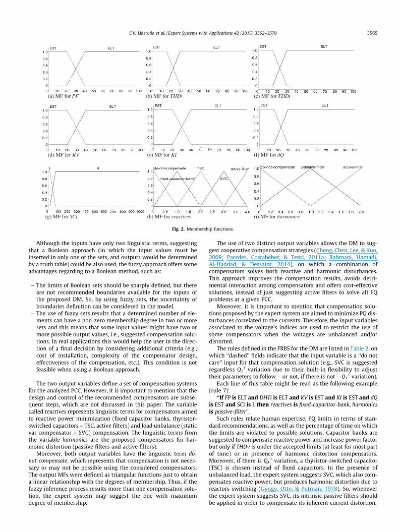
5. Simulation results
In order to evaluate the proposed expert system, a three phase5-node grid was simulated on PSCAD™ considering 5 different loadconfigurations. Fig. 3 depicts the simulated power circuit.
The loads are connected to node E (low voltage level), while thePCC is assumed to be at node D (medium voltage level), where PQcompensators are commonly installed. The PCC short-circuit cur-rent is 1584.98 \�69�A. Thus, next two sub-sections show theresults of applying the expert system using PCC measurements,for each load configuration and then, the results of applying thesolutions proposed by the DM in each case.
5.1. Application of the expert system
Table 3 describes the load configurations and the time intervalon which each load was connected to node E. Case 1 and case 6have same load configurations, but in 6 it was added 6% of 5th har-monic in the voltages at node C. For each case, total simulation andmeasurement time were 8.0 s.
Table 4 shows samples of stored power quality data from eachload condition and the correspondent time instant when they werecalculated. The time rate for storing the calculated power compo-nents and PQ indices was defined on a 60 Hz basis, it means, onesample per fundamental period. Thus, the stored data obtainedfrom the measurement device were processed and analyzed bythe DM using Matlab.
Table 5 depicts the input variables for the DM, the maximumRMS value of PCC currents (used to calculate the SCl and the TDDisamples shown on Table 4) and the compensation solutionssuggested by the expert system. In addition, Table 6 shows the
Fig. 3. 5-node power circu
activated rules and which one was selected by the DM, as the mostproper solution for each case.
Case 1 was a typical application of PF correction, where the loadis balanced, constant and free of harmonic distortion. Thus, the cor-responding rule from FRBS for this case was number 2, resultingfixed-capacitor-bank for reactives and do-not-compensate forharmonics.
Nevertheless, in case 6 (same load of case 1, but assuming dis-torted PCC voltages) the harmonic distortion identified at PCC volt-ages was higher than the adopted limit and, although it did notaffect too much the currents (TDDi was 1.859%), it could affect sig-nificantly the compensation if a capacitor bank would be applied.Thus, the suggestion of the expert system is active-filter for reac-tives and do-not-compensate for harmonics (rule 4).
In the next section the result of using just a capacitive bank forcase 6 will be discussed to confirm that it would not be a goodchoice.
In case 2, the existence of reactive power and distorted currentscontribute for a low PF during all the measurement interval. Con-sequently, the PCC voltages became distorted, but THDv is stillunder the recommended limit. In this case, the short circuit levelhas non-zero membership degrees for both MFs of SCl. Conse-quently, rules 7 and 11 from FRBS are activated (fixed-capacitor-bank for reactives, and passive-filter or active-filter for harmonics).However, one can observe in Table 6 that as the degree of member-ship of passive-filter is bigger than the degree of membership ofactive-filter, DM suggested rule 7.
In case 3, the load varies during the measurement time, result-ing in four different load profiles, as shown in Table 4. The averageQ1
+ is 344.2 kVAr and considering the values of Q1+ from Table 4,
this power component is out of the adopted boundaries (±30%deviation) for 74% of total measurement time, as indicated inTable 5. Moreover, the current distortion exceeds the pre-definedlimit during 42% of measurement time, which corresponds to thetime when the rectifier is turned on. Thus, by considering the reac-tive power variation and the harmonic distortion during a signifi-cant time interval, at the intermediary value of short circuit level,the activated rules in the FRBS were 8 and 12. In accordance tothe membership degrees illustrated in Table 6, the decision-makersuggests rule 8 as the outcome of the decision making process.
it simulated at PSCAD.
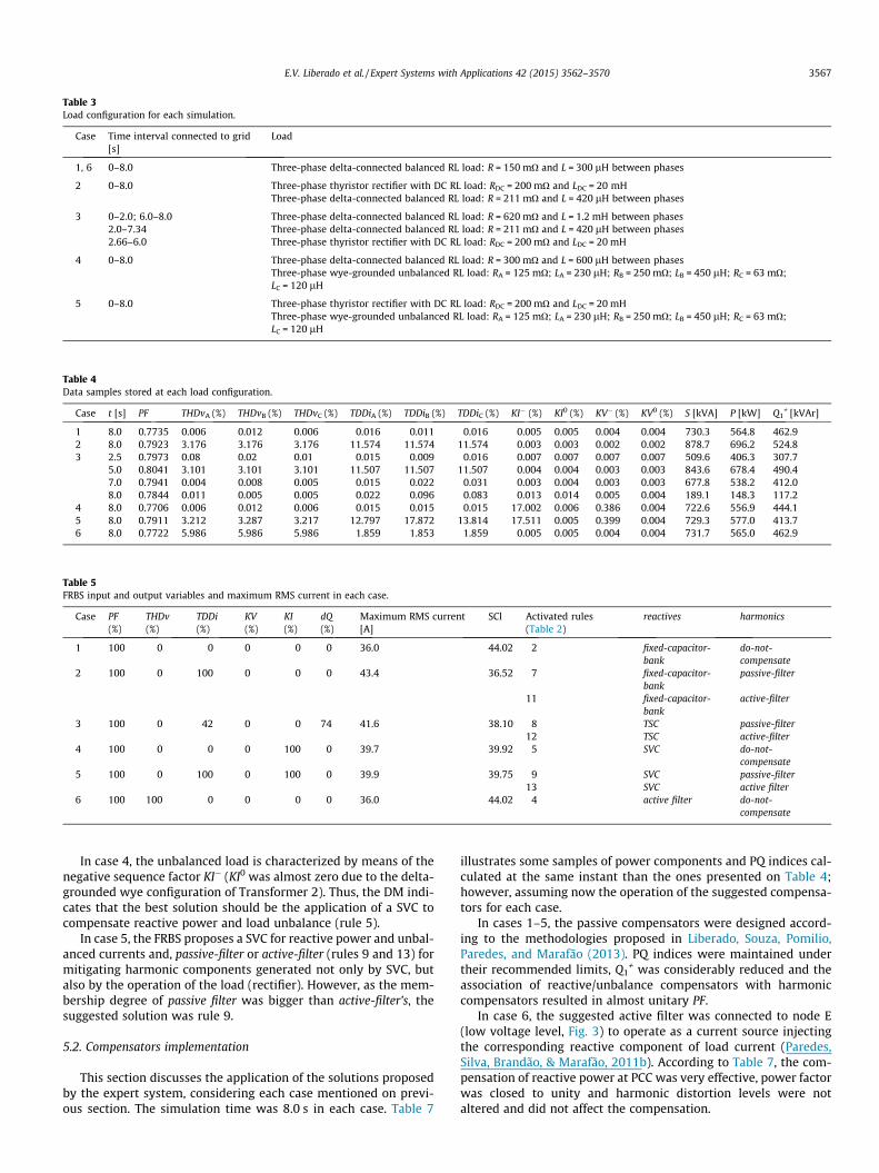
Table 3Load configuration for each simulation.
Case Time interval connected to grid[s]
Load
1, 6 0–8.0 Three-phase delta-connected balanced RL load: R = 150 mO and L = 300 lH between phases
2 0–8.0 Three-phase thyristor rectifier with DC RL load: RDC = 200 mO and LDC = 20 mHThree-phase delta-connected balanced RL load: R = 211 mO and L = 420 lH between phases
3 0–2.0; 6.0–8.0 Three-phase delta-connected balanced RL load: R = 620 mO and L = 1.2 mH between phases2.0–7.34 Three-phase delta-connected balanced RL load: R = 211 mO and L = 420 lH between phases2.66–6.0 Three-phase thyristor rectifier with DC RL load: RDC = 200 mO and LDC = 20 mH
4 0–8.0 Three-phase delta-connected balanced RL load: R = 300 mO and L = 600 lH between phasesThree-phase wye-grounded unbalanced RL load: RA = 125 mO; LA = 230 lH; RB = 250 mO; LB = 450 lH; RC = 63 mO;LC = 120 lH
5 0–8.0 Three-phase thyristor rectifier with DC RL load: RDC = 200 mO and LDC = 20 mHThree-phase wye-grounded unbalanced RL load: RA = 125 mO; LA = 230 lH; RB = 250 mO; LB = 450 lH; RC = 63 mO;LC = 120 lH
Table 4Data samples stored at each load configuration.
Case t [s] PF THDvA (%) THDvB (%) THDvC (%) TDDiA (%) TDDiB (%) TDDiC (%) KI� (%) KI0 (%) KV� (%) KV0 (%) S [kVA] P [kW] Q1+ [kVAr]
1 8.0 0.7735 0.006 0.012 0.006 0.016 0.011 0.016 0.005 0.005 0.004 0.004 730.3 564.8 462.92 8.0 0.7923 3.176 3.176 3.176 11.574 11.574 11.574 0.003 0.003 0.002 0.002 878.7 696.2 524.83 2.5 0.7973 0.08 0.02 0.01 0.015 0.009 0.016 0.007 0.007 0.007 0.007 509.6 406.3 307.7
5.0 0.8041 3.101 3.101 3.101 11.507 11.507 11.507 0.004 0.004 0.003 0.003 843.6 678.4 490.47.0 0.7941 0.004 0.008 0.005 0.015 0.022 0.031 0.003 0.004 0.003 0.003 677.8 538.2 412.08.0 0.7844 0.011 0.005 0.005 0.022 0.096 0.083 0.013 0.014 0.005 0.004 189.1 148.3 117.2
4 8.0 0.7706 0.006 0.012 0.006 0.015 0.015 0.015 17.002 0.006 0.386 0.004 722.6 556.9 444.15 8.0 0.7911 3.212 3.287 3.217 12.797 17.872 13.814 17.511 0.005 0.399 0.004 729.3 577.0 413.76 8.0 0.7722 5.986 5.986 5.986 1.859 1.853 1.859 0.005 0.005 0.004 0.004 731.7 565.0 462.9
Table 5FRBS input and output variables and maximum RMS current in each case.
Case PF(%)
THDv(%)
TDDi(%)
KV(%)
KI(%)
dQ(%)
Maximum RMS current[A]
SCl Activated rules(Table 2)
reactives harmonics
1 100 0 0 0 0 0 36.0 44.02 2 fixed-capacitor-bank
do-not-compensate
2 100 0 100 0 0 0 43.4 36.52 7 fixed-capacitor-bank
passive-filter
11 fixed-capacitor-bank
active-filter
3 100 0 42 0 0 74 41.6 38.10 8 TSC passive-filter12 TSC active-filter
4 100 0 0 0 100 0 39.7 39.92 5 SVC do-not-compensate
5 100 0 100 0 100 0 39.9 39.75 9 SVC passive-filter13 SVC active filter
6 100 100 0 0 0 0 36.0 44.02 4 active filter do-not-compensate
E.V. Liberado et al. / Expert Systems with Applications 42 (2015) 3562–3570 3567
In case 4, the unbalanced load is characterized by means of thenegative sequence factor KI� (KI0 was almost zero due to the delta-grounded wye configuration of Transformer 2). Thus, the DM indi-cates that the best solution should be the application of a SVC tocompensate reactive power and load unbalance (rule 5).
In case 5, the FRBS proposes a SVC for reactive power and unbal-anced currents and, passive-filter or active-filter (rules 9 and 13) formitigating harmonic components generated not only by SVC, butalso by the operation of the load (rectifier). However, as the mem-bership degree of passive filter was bigger than active-filter’s, thesuggested solution was rule 9.
5.2. Compensators implementation
This section discusses the application of the solutions proposedby the expert system, considering each case mentioned on previ-ous section. The simulation time was 8.0 s in each case. Table 7
illustrates some samples of power components and PQ indices cal-culated at the same instant than the ones presented on Table 4;however, assuming now the operation of the suggested compensa-tors for each case.
In cases 1–5, the passive compensators were designed accord-ing to the methodologies proposed in Liberado, Souza, Pomilio,Paredes, and Marafão (2013). PQ indices were maintained undertheir recommended limits, Q1
+ was considerably reduced and theassociation of reactive/unbalance compensators with harmoniccompensators resulted in almost unitary PF.
In case 6, the suggested active filter was connected to node E(low voltage level, Fig. 3) to operate as a current source injectingthe corresponding reactive component of load current (Paredes,Silva, Brandão, & Marafão, 2011b). According to Table 7, the com-pensation of reactive power at PCC was very effective, power factorwas closed to unity and harmonic distortion levels were notaltered and did not affect the compensation.
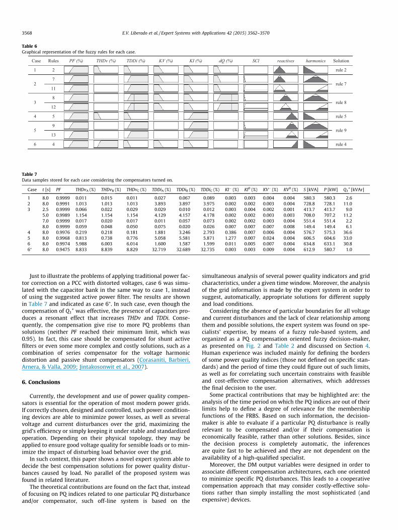
Table 6Graphical representation of the fuzzy rules for each case.
Case Rules PF (%) THDv (%) TDDi (%) KV (%) KI (%) dQ (%) SCl reactives harmonics Solution
1 2 rule 2
27
rule 711
38
rule 812
4 5 rule 5
59
rule 913
6 4 rule 4
Table 7Data samples stored for each case considering the compensators turned on.
Case t [s] PF THDvA (%) THDvB (%) THDvC (%) TDDiA (%) TDDiB (%) TDDiC (%) KI� (%) KI0 (%) KV� (%) KV0 (%) S [kVA] P [kW] Q1+ [kVAr]
1 8.0 0.9999 0.011 0.015 0.011 0.027 0.067 0.089 0.003 0.003 0.004 0.004 580.3 580.3 2.62 8.0 0.9991 1.013 1.013 1.013 3.893 3.897 3.975 0.002 0.002 0.003 0.004 728.8 728.1 11.03 2.5 0.9999 0.066 0.022 0.029 0.029 0.010 0.012 0.003 0.004 0.002 0.001 413.7 413.7 9.0
5.0 0.9989 1.154 1.154 1.154 4.129 4.157 4.178 0.002 0.002 0.003 0.003 708.0 707.2 11.27.0 0.9999 0.017 0.020 0.017 0.011 0.057 0.073 0.002 0.002 0.003 0.004 551.4 551.4 2.28.0 0.9999 0.059 0.048 0.050 0.075 0.020 0.026 0.007 0.007 0.007 0.008 149.4 149.4 6.1
4 8.0 0.9976 0.219 0.218 0.181 1.881 3.246 2.793 0.386 0.007 0.006 0.004 576.7 575.3 36.65 8.0 0.9968 0.813 0.738 0.776 5.058 5.581 5.871 1.277 0.007 0.024 0.004 606.5 604.6 33.06 8.0 0.9974 5.988 6.003 6.014 1.600 1.587 1.599 0.011 0.005 0.007 0.004 634.8 633.1 30.86⁄ 8.0 0.9475 8.833 8.839 8.829 32.719 32.689 32.735 0.003 0.003 0.009 0.004 612.9 580.7 1.0
3568 E.V. Liberado et al. / Expert Systems with Applications 42 (2015) 3562–3570
Just to illustrate the problems of applying traditional power fac-tor correction on a PCC with distorted voltages, case 6 was simu-lated with the capacitor bank in the same way to case 1, insteadof using the suggested active power filter. The results are shownin Table 7 and indicated as case 6⁄. In such case, even though thecompensation of Q1
+ was effective, the presence of capacitors pro-duces a resonant effect that increases THDv and TDDi. Conse-quently, the compensation give rise to more PQ problems thansolutions (neither PF reached their minimum limit, which was0.95). In fact, this case should be compensated for shunt activefilters or even some more complex and costly solutions, such as acombination of series compensator for the voltage harmonicdistortion and passive shunt compensators (Corasaniti, Barbieri,Arnera, & Valla, 2009; Jintakosonwit et al., 2007).
6. Conclusions
Currently, the development and use of power quality compen-sators is essential for the operation of most modern power grids.If correctly chosen, designed and controlled, such power condition-ing devices are able to minimize power losses, as well as severalvoltage and current disturbances over the grid, maximizing thegrid’s efficiency or simply keeping it under stable and standardizedoperation. Depending on their physical topology, they may beapplied to ensure good voltage quality for sensible loads or to min-imize the impact of disturbing load behavior over the grid.
In such context, this paper shows a novel expert system able todecide the best compensation solutions for power quality distur-bances caused by load. No parallel of the proposed system wasfound in related literature.
The theoretical contributions are found on the fact that, insteadof focusing on PQ indices related to one particular PQ disturbanceand/or compensator, such off-line system is based on the
simultaneous analysis of several power quality indicators and gridcharacteristics, under a given time window. Moreover, the analysisof the grid information is made by the expert system in order tosuggest, automatically, appropriate solutions for different supplyand load conditions.
Considering the absence of particular boundaries for all voltageand current disturbances and the lack of clear relationship amongthem and possible solutions, the expert system was found on spe-cialists’ expertise, by means of a fuzzy rule-based system, andorganized as a PQ compensation oriented fuzzy decision-maker,as presented on Fig. 2 and Table 2 and discussed on Section 4.Human experience was included mainly for defining the bordersof some power quality indices (those not defined on specific stan-dards) and the period of time they could figure out of such limits,as well as for correlating such uncertain constrains with feasibleand cost-effective compensation alternatives, which addressesthe final decision to the user.
Some practical contributions that may be highlighted are: theanalysis of the time period on which the PQ indices are out of theirlimits help to define a degree of relevance for the membershipfunctions of the FRBS. Based on such information, the decision-maker is able to evaluate if a particular PQ disturbance is reallyrelevant to be compensated and/or if their compensation iseconomically feasible, rather than other solutions. Besides, sincethe decision process is completely automatic, the inferencesare quite fast to be achieved and they are not dependent on theavailability of a high-qualified specialist.
Moreover, the DM output variables were designed in order toassociate different compensation architectures, each one orientedto minimize specific PQ disturbances. This leads to a cooperativecompensation approach that may consider costly-effective solu-tions rather than simply installing the most sophisticated (andexpensive) devices.

E.V. Liberado et al. / Expert Systems with Applications 42 (2015) 3562–3570 3569
Finally, the analysis of PQ indices related to both currents andvoltages expands the understanding about their relations to possi-ble solutions and allows better choices when designing compensa-tion systems, as depicted in case 6.
Some limitations of the proposed expert system would be: (1)the definition of the time interval to make the measurements iscase-dependent and, if the load dynamic is not constant or known,the characterization of all PQ disturbances would require long-time measurement campaigns; (2) the lack of standardization ofPQ indices and their limits, and the fact that most of the powermeters do not calculate all of them, would require the using of dif-ferent instruments to acquire the relevant data or the employmentof specific PQ meter in order to embed or correlate the expert sys-tem in/to a single hardware.
Although the good results from using the proposed expert sys-tems, future improvements are expected based on the inclusion ofadditional and/or new power quality indices, in order to improvethe PQ characterization at the PCC and, the inclusion of compensa-tor’s design procedures in the expert system, in such a way that theexpert system may not only suggest the compensation solution butoffer basic specification for the compensators (e.g., nominal power,number of harmonic components to be compensated, etc.). Fur-thermore, some complementary information about the rated priceof each compensator may be included in the FRBS. Finally, theimplementation of the expert system on an embedded system, aswell as the use of the proposed approach in on-line applicationsfor smart grids (on which the expert system could manage the dis-tribution of the compensation demand among available compensa-tors), is expected.
Acknowledgements
The authors wish to express their gratitude to FAPESP (SãoPaulo Research Foundation, Process 2012/14014-0), CNPq (Process487471/2012-1) and Capes for supporting this research.
References
Akagi, H., Watanabe, E. H., & Aredes, M. (2007). Instantaneous power theory andapplications to power conditioning (1st ed.). Wiley-IEEE Press.
Arghandeh, R., von Meier, A., & Broadwater, R. (2014). Phasor-based approach forharmonic assessment from multiple distributed energy resources. InProceedings of IEEE PES general meeting conference & exposition (p. 1—5).
Banerjee, A., Mukherjee, V., & Ghoshal, S. P. (2014). Intelligent fuzzy-based reactivepower compensation of an isolated hybrid power system. International Journalof Electrical Power and Energy Systems, 57, 164–177.
Bellman, R. E., & Zadeh, L. A. (1970). Decision-making in a fuzzy environment.Management Science, Application Series, 17, B141–B164.
Bhattacharya, S. K., & Goswami, S. K. (2009). A new fuzzy based solution of thecapacitor placement problem in radial distribution system. Expert Systems withApplications, 36, 4207–4212.
Bisanovic, S., Hajro, M., & Samardzic, M. (2014). One approach for reactive powercontrol of capacitor banks in distribution and industrial networks. InternationalJournal of Electrical Power and Energy Systems, 60, 67–73.
Bollen, M. H. J. (2003). What is power quality? Electric Power Systems Research, 66,5–14.
Caia, Y. P., Huangc, G. H., Lina, Q. G., Niea, X. H., & Tana, Q. (2009). An optimization-model-based interactive decision support system for regional energymanagement systems planning under uncertainty. Expert Systems withApplications, 36, 3470–3482.
Chang, Y. (2010). Integration of SQP and PSO for optimal planning of harmonicfilters. Expert Systems with Applications, 37, 2522–2530.
Chang, Y., Low, C., & Hung, S. (2009). Integrated feasible direction method andgenetic algorithm for optimal planning of harmonic filters with uncertaintyconditions. Expert Systems with Applications, 36, 3946–3955.
Cheng, C. (2011). Design of output filter for inverters using fuzzy logic. ExpertSystems with Applications, 38, 8639–8647.
Cheng, P. T., Chen, C., Lee, T. L., & Kuo, S. (2009). A cooperative imbalancecompensation method for distributed-generation interface converters. IEEETransactions on Industry Applications, 45, 805–815.
Chompoo-Inwai, C., & Mungkornassawakul, J. (2013). A smart recording poweranalyzer prototype using lab view and low-cost data acquisition (DAQ) in beinga smart renewable monitoring system. In Proceedings of IEEE green technologiesconference (pp. 49–56).
Corasaniti, V. F., Barbieri, M. B., Arnera, P. L., & Valla, M. I. (2009). Hybrid active filterfor reactive and harmonics compensation in a distribution network. IEEETransactions on Industrial Electronics, 56, 670–677.
Currence, E. J., Plizga, J. E., & Nelson, H. N. (1995). Harmonic resonance at a medium-sized industrial plant. IEEE Transactions on Industry Applications, 31, 682–690.
Faisal, M., Mohamed, A., Shareef, H., & Hussain, A. (2011). Power quality diagnosisusing time frequency analysis and rule based techniques. Expert Systems withApplications, 38, 12592–12598.
Galvão, T. M., Belchior, F. N., Silveira, P. M., & Ribeiro, P. F. (2014). Comparativeanalysis of power quality instruments measuring voltage and power. InProceedings of IEEE 16th international conference on harmonics and quality ofpower (ICHQP) (pp. 762–767).
Golovanov, N., Lazaroiu, G. C., & Porumb, R. (2013). Wind generation assessmentproposal by experimental harmonic and distortion factor analysis. InProceedings of 48th international universities’ power engineering conference(UPEC) (pp. 1–4).
Gunal, S., Gerek, O. N., Ece, D. G., & Edizkan, R. (2009). The search for optimal featureset in power quality event classification. Expert Systems with Applications, 36,10266–10273.
Gyugy, L., Otto, R. A., & Putman, T. H. (1978). Principles and applications of static,thyristor-controlled shunt compensators. IEEE Transactions on Power Apparatusand Systems, 97, 1935–1945.
Hashemi, S., & Aghamohammad, M. R. (2013). Wavelet based feature extraction ofvoltage profile for online voltage stability assessment using RBF neural network.International Journal of Electrical Power and Energy Systems, 49, 86–94.
Hassan, L. H., Moghavvemi, M., Almurib, H. A. F., & Steinmayer, O. (2013). Currentstate of neural networks applications in power system monitoring and control.International Journal of Electrical Power and Energy Systems, 51, 134–144.
IEEE – Institute of Electrical and Electronics Engineers. (1993). IEEE recommendedpractices and requirements for harmonic control in electrical power systems. InIEEE Standard (pp. 519–1992).
IEEE – Institute of Electrical and Electronics Engineers. (2010). IEEE standarddefinitions for the measurement of electrical power quantities under sinusoidal,nonsinusoidal, balanced or unbalanced conditions. IEEE Std 1459-2010.
Jegathesan, V., & Jerome, J. (2011). Elimination of lower order harmonics in voltagesource inverter feeding an induction motor drive using evolutionary algorithms.Expert Systems with Applications, 38, 692–699.
Jintakosonwit, P., Srianthumrong, S., & Jintagosonwit, P. (2007). Implementation andperformance of an anti-resonance hybrid delta-connected capacitor bank forpower factor correction. IEEE Transactions on Power Electronics, 22, 2543–2551.
Kriukov, A., Grigoras, G., Scarlatache, F., Ivanov, O., & Vicol, B. (2014). Use of fuzzytechniques in reliability assessment of electric distribution systems. InProceedings of IEEE 16th international conference on harmonics and quality ofpower (ICHQP) (pp. 29–33).
Liberado, E. V., Souza, W. A., Pomilio, J. A., Paredes, H. K. M., & Marafão, F. P. (2013).Design of static var compensators using a general reactive energy definition.Przeglad Elektrotechniczny (Electrical Review), 89, 233–238.
Low, C., Chang, Y., & Hung, S. (2009). An application of sequential neural-networkapproximation for sitting and sizing passive harmonic filters. Expert Systemswith Applications, 36, 2910–2920.
Marafão, F. P., Souza, W. A., Liberado, E. V., Silva, L. C. P., & Paredes, H. K. M. (2013).Load analyser using conservative power theory. Przeglad Elektrotechniczny(Electrical Review), 12, 1–6.
Morsi, W. G., & El-Hawary, M. E. (2008a). A new fuzzy-based representative qualitypower factor for nonsinusoidal situations. IEEE Transactions on Power Delivery,23, 930–936.
Morsi, W. G., & El-Hawary, M. E. (2008b). A new fuzzy-based representative qualitypower factor for unbalanced three-phase systems with nonsinusoidalsituations. IEEE Transactions on Power Delivery, 23, 2426–2438.
Obulesu, Y. P., Reddy, M. V., & Kusumalatha, Y. (2014). A %THD analysis of industrialpower distribution systems with active power filter-case studies. InternationalJournal of Electrical Power and Energy Systems, 60, 107–120.
Paredes, H. K. M., Costabeber, A., & Tenti, P. (2011a). Application of conservativepower theory to cooperative control of distributed compensators in smart grids.Przeglad Elektrotechniczny (Electrical Review), 87, 1–7.
Paredes, H. K. M., Silva, L. C. P., Brandão, D., & Marafão, F. P. (2011b). Possible shuntcompensation strategies based on conservative power theory. PrzegladElektrotechniczny (Electrical Review), 87, 34–39.
Phipps, J. K., Nelson, J. P., & Sen, P. K. (1994). Power quality and harmonics ondistribution system. IEEE Transactions on Industry Applications, 30, 476–484.
Piltan, M., Mehmanchi, E., & Ghaderi, S. F. (2012). Proposing a decision-makingmodel using analytical hierarchy process and fuzzy expert system forprioritizing industries in installation of combined heat and power systems.Expert Systems with Applications, 39, 1124–1133.
Rahmani, S., Hamadi, A., Al-Haddad, K., & Dessaint, L. A. (2014). A combination ofshunt hybrid power filter and thyristor-controlled reactor for power quality.IEEE Transactions on Industrial Electronics, 61, 2152–2164.
Ray, R. N., Chatterjee, D., & Goswami, S. K. (2010). A PSO based optimal switchingtechnique for voltage harmonic reduction of multilevel inverter. Expert Systemswith Applications, 37, 7796–7801.
Sahin, S., Tolun, M. R., & Hassanpour, R. (2012). Hybrid expert systems: A survey ofcurrent approaches and applications. Expert Systems with Applications, 39,4609–4617.
Salem, M., Mohamed, A., & Samad, S. A. (2010). Rule based system for power qualitydisturbance classification incorporating S-transform features. Expert Systemswith Applications, 37, 3229–3235.

3570 E.V. Liberado et al. / Expert Systems with Applications 42 (2015) 3562–3570
Singh, B., Al-Haddad, K., & Chandra, A. (1999). A review of active filters for powerquality improvement. IEEE Transactions on Industrial Electronics, 46, 960–971.
Su, H. J., Chang, G. W., Hsu, L. Y., Lu, H. J., Lee, Y. D., Chang, Y. R., & Lin, J. H. (2013).Development of power quality analysis platform for INER Microgrid. InProceedings of IEEE power and energy society general meeting (PES) (pp. 1–5).
Suslov, K. V., Solonina, N. N., & Smirnov, A. S. (2014). Distributed power qualitymonitoring. In Proceedings of IEEE 16th international conference on harmonics andquality of power (ICHQP) (pp. 517–520).
Tutkun, N. (2010). Improved power quality in a single-phase PWM inverter voltagewith bipolar notches through the hybrid genetic algorithms. Expert Systems withApplications, 37, 5614–5620.
Vallée, F., Klonari, V., Lisiecki, T., Durieux, O., Moiny, F., & Lobry, J. (2013).Development of a probabilistic tool using Monte Carlo simulation and smart
meters measurements for the long term analysis of low voltage distributiongrids with photovoltaic generation. International Journal of Electrical Power andEnergy Systems, 53, 468–477.
Wang, M., & Tseng, Y. (2011). A novel analytic method of power quality usingextension genetic algorithm and wavelet transform. Expert Systems withApplications, 38, 12491–12496.
Yang, Z., Cao, J., Xu, Y., Zhang, H., Yu, P., & Yao., S. (2013). Data Cleaning for PowerQuality Monitoring. In Proceedings of fourth international conference onnetworking and distributed computing (ICNDC) (pp. 111–115).
Zhang, J., Yan, W., Yang, Q., Bao, Z., & Sun, R. (2013). Power quality measurementand analysis of offshore wind farm based on PSCAD/EMTDC models. InProceedings of sixth international conference on advanced computationalintelligence (ICACI) (pp. 371–375).
Related Documents