Novel Compact Ceramic Heat Exchanger For Solid Oxide Fuel Cell Cathode Air Preheater Application DOE Program Manager: Sydni Credle, Ph.D. Crosscutting Research Division National Energy Technology Laboratory (NETL) J. L. Córdova, Ph.D. J. F. Walton II H. Heshmat, Ph.D. (PI)

Welcome message from author
This document is posted to help you gain knowledge. Please leave a comment to let me know what you think about it! Share it to your friends and learn new things together.
Transcript
Novel Compact Ceramic Heat ExchangerFor Solid Oxide Fuel Cell Cathode Air Preheater
Application
DOE Program Manager: Sydni Credle, Ph.D.Crosscutting Research Division
National Energy Technology Laboratory (NETL)
J. L. Córdova, Ph.D. J. F. Walton II H. Heshmat, Ph.D. (PI)

MiTi: What We DoORC Turbogenerator
Hydrogen Pipeline Compressor
Hydrogen Blower Fuel Cell CompressorAir Cycle Machine
65 kWe @ 30,000 rpm 120,000 rpm 360,000 rpm
60,000 rpm 60 kWe @ 60,000 rpmFlywheel Electromechanical Battery
By Use of Ultra High Speed, We Deliver Compact, Power-Dense Engines!
120,000 rpm
Micro Machining500,000 rpm

At the Core: MiTi’s Advanced Foil Bearings
• Oil-Free Maintenance/Contamination Free
• Ultra High Speed: Proven to 1,000,000 rpm
• With Korolon® 1350/2250 High Temperature Operation Turbine Exhaust Conditions, up to 810oC (1500oF)
• Negligible Friction Power Loss High Mechanical Efficiency
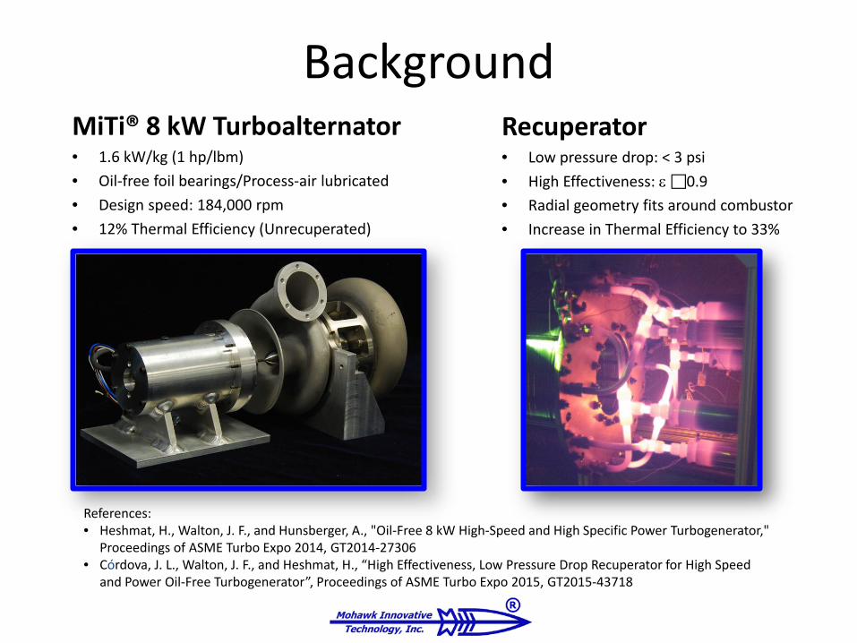
BackgroundMiTi® 8 kW Turboalternator• 1.6 kW/kg (1 hp/lbm)• Oil-free foil bearings/Process-air lubricated• Design speed: 184,000 rpm• 12% Thermal Efficiency (Unrecuperated)
Recuperator• Low pressure drop: < 3 psi• High Effectiveness: ε0.9• Radial geometry fits around combustor• Increase in Thermal Efficiency to 33%
References:• Heshmat, H., Walton, J. F., and Hunsberger, A., "Oil-Free 8 kW High-Speed and High Specific Power Turbogenerator,"
Proceedings of ASME Turbo Expo 2014, GT2014-27306• Córdova, J. L., Walton, J. F., and Heshmat, H., “High Effectiveness, Low Pressure Drop Recuperator for High Speed
and Power Oil-Free Turbogenerator”, Proceedings of ASME Turbo Expo 2015, GT2015-43718

Project Team
MiTi• Hooshang Heshmat, Ph.D.
– Principal Investigator– Technical Director
• James F. Walton– Sr. Program Manager
• Jose L. Cordova, Ph.D.– Program Manager– Project Engineer
FuelCell Energy, Inc.• Hossein Ghezel-Ayagh, Ph.D.
– FCE Lead
• Robert Sanderson, P.E.– Systems Engineer
• Stephen Jolly– Systems Design Engineer
Objective
• Develop a High Heat Transfer Effectiveness, Low Pressure Drop Ceramic Heat Exchanger for Application as Solid Oxide Fuel Cell Cathode (SOFC) Air Preheater.– Possible Materials: Ceramics, Cermet, Hybrid
Ceramics, Elastic Ceramics
Purpose of Heat Exchanger
• SOFC cathode requires a fresh air supply at 700oC for operation.
• Anode exhaust contains CO and H2.– These are post-combusted in a catalytic oxidizer,
yielding high temperature heat.– Heat is recovered in heat exchanger and used to
preheat supplied air.
(Continued)
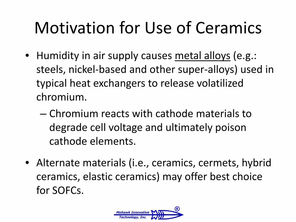
Motivation for Use of Ceramics• Humidity in air supply causes metal alloys (e.g.:
steels, nickel-based and other super-alloys) used in typical heat exchangers to release volatilized chromium.– Chromium reacts with cathode materials to
degrade cell voltage and ultimately poison cathode elements.
• Alternate materials (i.e., ceramics, cermets, hybrid ceramics, elastic ceramics) may offer best choice for SOFCs.

Overview of Approach• Leverage MiTi’s Novel Gas Turbine Recuperator
– Original application: 8 kW gas turbine-based turboalternator• Turbine engine specifications required low pressure drop (3 to 5 psi)
– Attained around 90% heat transfer effectiveness at engine operating conditions.
• Extend Technology To SOFC– Ceramic Materials– Reduce pressure drop
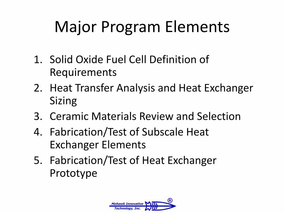
Major Program Elements
1. Solid Oxide Fuel Cell Definition of Requirements
2. Heat Transfer Analysis and Heat Exchanger Sizing
3. Ceramic Materials Review and Selection4. Fabrication/Test of Subscale Heat
Exchanger Elements5. Fabrication/Test of Heat Exchanger
Prototype

IDENTIFICATION OF SOFC REQUIREMENTS
Target Application: Solid Oxide Fuel Cell Operating Conditions

Target Application
• FuelCell Energy Inc.– Proof Of Concept 50 kWe
SOFC
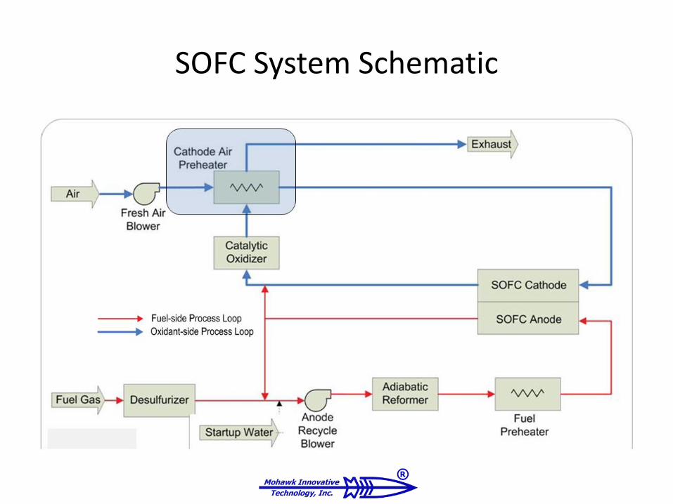
SOFC System Schematic
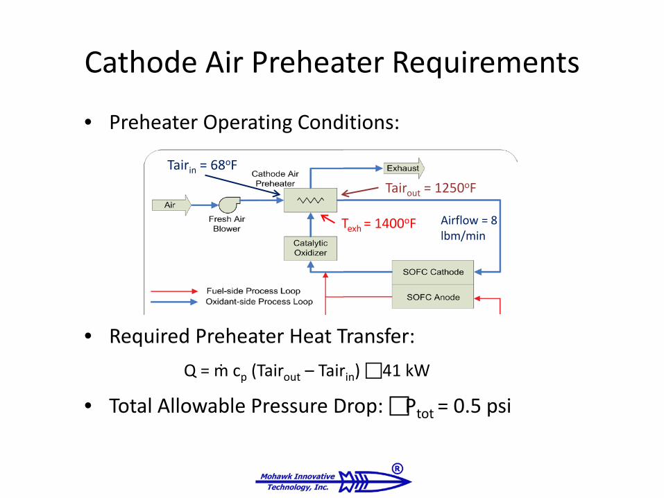
Cathode Air Preheater Requirements
• Preheater Operating Conditions:
• Required Preheater Heat Transfer:Q = ṁ cp (Tairout – Tairin) 41 kW
• Total Allowable Pressure Drop: Ptot = 0.5 psi
Airflow = 8 lbm/min
Tairin = 68oFTairout = 1250oF
Texh = 1400oF
MiTi’S RECUPERATOR EXPERIENCEHeat Transfer Analysis and Heat Exchanger Sizing

MiTi’s Recuperator Experience
• Overlapping quasi-helical flow paths– Patent Pending: U.S. Provisional
Patent Application US62/040,559
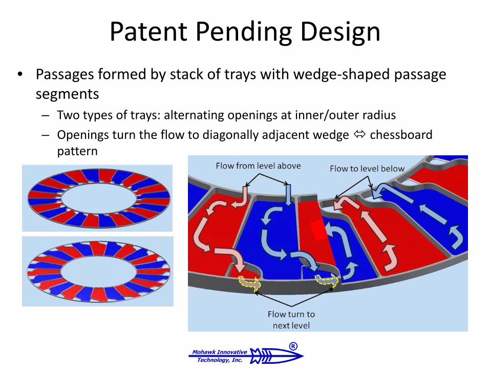
Patent Pending Design• Passages formed by stack of trays with wedge-shaped passage
segments– Two types of trays: alternating openings at inner/outer radius– Openings turn the flow to diagonally adjacent wedge chessboard
pattern
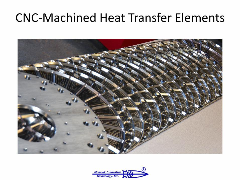
CNC-Machined Heat Transfer Elements
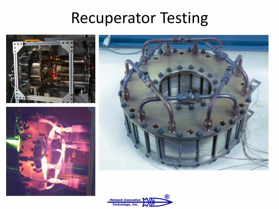
Recuperator Testing

Experimental P vs. ṁ Performance
• Pressure drop designed to satisfy engine constraints.
– Turbine design pressure drop too high for fuel cell
• SOFC imposes no weight or size limit constraint Pressure drop can be designed to be significantly lower.
7/30/2015
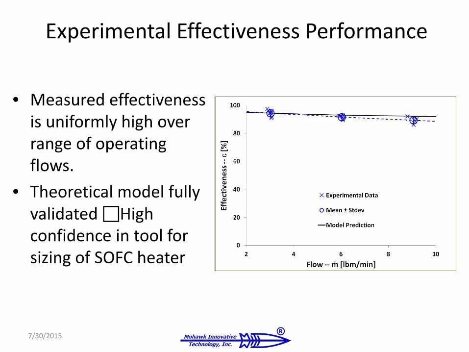
Experimental Effectiveness Performance
7/30/2015
• Measured effectiveness is uniformly high over range of operating flows.
• Theoretical model fully validated High confidence in tool for sizing of SOFC heater

HEAT EXCHANGER DESIGNHeat Transfer Analysis and Heat Exchanger Sizing

Preliminary Heat Exchanger Design
• MiTi’s Modeling Tool– Written in Mathematica– Solves fundamental heat
transfer governing equations
• First Iteration Sizing Results:– Preheated air temperature
Tairout = 1200oF
– Pressure drop P = 0.33 psi– Effectiveness = 85%

Preliminary Heat Exchanger Design
• Subdivide hot and cold flow into 12 Passages Each (Total of 24 Passages Wide),
• Make Stack of 12 Layers Deep• Geometry of heat exchange
elements:– Total length single flow path: 6.0 m– Wall thickness: 0.004 m– Passage width: 0.05 m– Passage height: 0.015 m
24 Passages
12 Layers

Parametric Study For Design Optimization
Heat transfer between flows:Basic Heat Transfer Element
Overall Heat Transfer Coeff.:
Cool Stream• Conv. Coff.: hc• Temp.: Tc
Hot Stream• Conv. Coff.: hh• Temp.: Th
Walls:•Thickness: L•Conductivity: k
Preliminary Sizing:
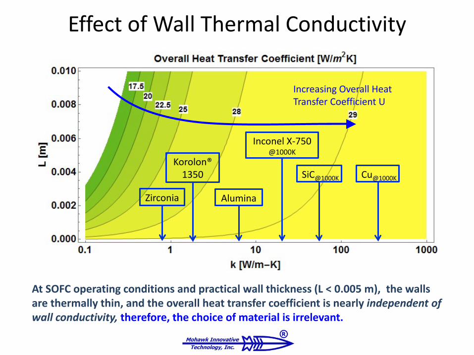
Effect of Wall Thermal Conductivity
Cu@1000KSiC@1000K
Inconel X-750@1000K
Alumina
Korolon®1350
Zirconia
Increasing Overall Heat Transfer Coefficient U
At SOFC operating conditions and practical wall thickness (L < 0.005 m), the walls are thermally thin, and the overall heat transfer coefficient is nearly independent of wall conductivity, therefore, the choice of material is irrelevant.

Heat Exchanger Preliminary Layout
• Modular segments form overlapping quasi-helical flow paths.
• Patent Pending: U.S. Provisional Patent Application US62/040,559
• Design allows to add or remove segments according to flow, pressure drop, or heat exchange rate requirements.

FABRICATION TRIALSMaterial and Fabrication Considerations

Component Fabrication Testing
• Material Selected: Alumina-Silicate Machinable Ceramic
– Machined in Green State– Partially Fired to 1600oF
• Geometric Tolerance 1%

Seal Pressure/Leak Tests
• Successfully Held 0.5 psi• Total Allowable Drop over Device:
0.33 psi, or less than 0.03 psi per Passage Segment (Assuming each Passage is Made from 10 Segments) Huge Pressure Margin

Closing Remarks
• Status: Program Well Underway– Identified SOFC
Preheater Requirements– Preliminary Preheater
Design Established– Materials Selection Done– Prototype Fabrication
Trials Underway
• Next Steps– Define/Design Interface
to SOFC– Performance Tests on
Subscale Device– Integrate Prototype
• Long Duration Testing– 1000 Hours on SOFC
• Post-Test Inspection
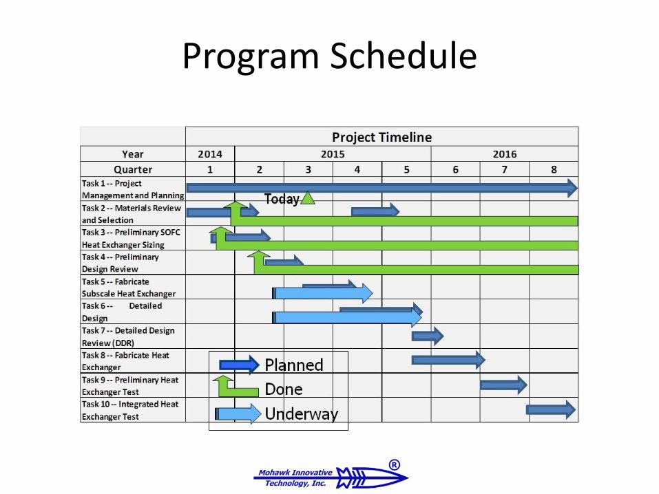
Program Schedule

Acknowledgement
The authors gratefully acknowledge the support and interest of DOE and particularly of Dr. Sydni Credle, at the Crosscutting Research Division, NETL.

Related Documents