Wright State University Wright State University CORE Scholar CORE Scholar Browse all Theses and Dissertations Theses and Dissertations 2018 Novel Auto-Calibrating Neural Motor Decoder for Robust Novel Auto-Calibrating Neural Motor Decoder for Robust Prosthetic Control Prosthetic Control Andrew Earl Montgomery Wright State University Follow this and additional works at: https://corescholar.libraries.wright.edu/etd_all Part of the Biomedical Engineering and Bioengineering Commons Repository Citation Repository Citation Montgomery, Andrew Earl, "Novel Auto-Calibrating Neural Motor Decoder for Robust Prosthetic Control" (2018). Browse all Theses and Dissertations. 2242. https://corescholar.libraries.wright.edu/etd_all/2242 This Thesis is brought to you for free and open access by the Theses and Dissertations at CORE Scholar. It has been accepted for inclusion in Browse all Theses and Dissertations by an authorized administrator of CORE Scholar. For more information, please contact [email protected].

Welcome message from author
This document is posted to help you gain knowledge. Please leave a comment to let me know what you think about it! Share it to your friends and learn new things together.
Transcript

Wright State University Wright State University
CORE Scholar CORE Scholar
Browse all Theses and Dissertations Theses and Dissertations
2018
Novel Auto-Calibrating Neural Motor Decoder for Robust Novel Auto-Calibrating Neural Motor Decoder for Robust
Prosthetic Control Prosthetic Control
Andrew Earl Montgomery Wright State University
Follow this and additional works at: https://corescholar.libraries.wright.edu/etd_all
Part of the Biomedical Engineering and Bioengineering Commons
Repository Citation Repository Citation Montgomery, Andrew Earl, "Novel Auto-Calibrating Neural Motor Decoder for Robust Prosthetic Control" (2018). Browse all Theses and Dissertations. 2242. https://corescholar.libraries.wright.edu/etd_all/2242
This Thesis is brought to you for free and open access by the Theses and Dissertations at CORE Scholar. It has been accepted for inclusion in Browse all Theses and Dissertations by an authorized administrator of CORE Scholar. For more information, please contact [email protected].

NOVEL AUTO-CALIBRATING NEURAL MOTOR DECODER FOR ROBUST
PROSTHETIC CONTROL
A thesis submitted in partial fulfillment of the
requirements for the degree of
Master of Science in Biomedical Engineering
By
ANDREW EARL MONTGOMERY
B.S.B.M.E., Wright State University, 2015
2018
Wright State University

WRIGHT STATE UNIVERSITY
GRADUATE SCHOOL
June 6, 2018
I HEREBY RECOMMEND THAT THE THESIS PREPARED UNDER
MY SUPERVISON BY Andrew Earl Montgomery ENTITLED Novel Auto-
Calibrating Neural Motor Decoder for Robust Prosthetic Control BE ACCEPTED
IN PARTIAL FULFILLMENT OF THE REQUIREMENTS FOR THE DEGREE OF
Master of Science in Biomedical Engineering.
Committee on
Final Examination
Sherif Elbasiouny, Ph.D.
Caroline Cao, Ph.D.
Subhashini Ganapathy, Ph.D.
Barry Milligan, Ph.D.
Interim Dean of the Graduate School
Sherif Elbasiouny, Ph.D.
Thesis Director
Jaime Ramirez-Vick, Ph.D.
Chair, Department of Biomedical, Industrial,
and Human Factors Engineering

iii
ABSTRACT
Montgomery, Andrew Earl. M.S.B.M.E. Department of Biomedical, Industrial, and
Human Factors Engineering. Wright State University, 2018. Novel Auto-Calibrating
Neural Motor Decoder for Robust Prosthetic Control.
The overarching goal of this project is to develop novel neural motor decoders for
prosthetic control. EMG decoders measure the activity from an intact but non-target
muscle. Neural motor decoders transform the signal measured from the severed motor
axons of the target muscle. A multi-scale, highly-realistic computer model of a spinal
motor pool was developed (Allen & Elbasiouny, 2018) to serve as a computational
platform for decoder development and testing. A firing rate-based algorithm was
developed to transform the aggregate discharge of the motor pool into a command signal
to control the simulated prosthetic MuJoCo hand. This algorithm was informed by
cellular neurophysiology knowledge of how motor neurons are activated by synaptic
inputs to generate action potentials. Our results show that this neural motor decoder is
fast (i.e., decoding time < 10 ms), reliable (i.e., accurate decoding of inputs varying in
waveform, magnitude, and speed), and robust (i.e., accurate decoding of varying
activation schemes) in controlling the prosthesis. Additionally, this decoder was
successful in automatically adapting, in real-time, to dynamic changes in the synaptic
input signals and decoding its magnitude and rate of activation; thus, minimizing the
need for frequent daily calibrations by the amputee.
iv
TABLE OF CONTENTS PAGE#
1. INTRODUCTION…………………………………………………………………………………………........1
1.1 MOTIVATION…………………………………………………………………………………………….…1
1.2 BACKGROUND……………………………………………………………………………………….…….1
2. LITERATURE REVIEW: PAST TO PRESENT UPPER LIMB PROSTHETICS……….....4
2.1 ADVANCEMENTS IN PROSTHETIC HARDWARE…………………………………….……4
2.2 ADVANCEMENTS IN PROSTHETIC CONTROL…………………………………………..…11
3. MOTOR SYSTEM PHYSIOLOGY………………………………………………………………....……..16
3.1 NEURAL SIGNALS………………………………………………………………………..…..………...16
3.2 THE MOTOR PATHWAY………………………………………………………………..…………….19
3.3 MOTOR UNITS…………………………………………………………………………...………...…….23
4. LITERATURE REVIEW: RESEARCH APPROACHES……………………………..….…...……27
4.1 BIOLOGICAL CONTROL SIGNALS……………………………………………………......……..28
4.2 SIGNAL PROCESSING AND FEATURE EXTRACTION……………………………...……35
4.3 DECODING AND CLASSIFICATION………………………………………………………………40
5. THE DEVELOPMENT OF AN AUTO-CALIBRATING NEURAL MOTOR DECODER..41
5.1 PROBLEM STATEMENT............................................................................................41
5.2 WHY NEURAL MODELING?.....................................................................................44
5.3 METHODS..................................................................................................................45
5.4 RESULTS.....................................................................................................................52
5.5 DISCUSSION...............................................................................................................77
6. CONCLUSION..................................................................................................................85
7. REFERENCES..................................................................................................................87
v
LIST OF FIGURES
Figure Page #
1. Body powered upper limb prosthetic.....................................................................3
2. The Utah Artificial Arm..........................................................................................5
3. Shoulder level configuration of DEKA arm............................................................7
4. i-Limb and BE-bionic commercial prosthetic devices...........................................9
5. Foot Controls for DEKA Arm.................................................................................12
6. Camera controlled prosthetic.................................................................................15
7. Schematic of Action Potential................................................................................18
8. Axonal propagation of action potential..................................................................19
9. Schematic of Motor Pathway to Upper Limb.........................................................21
10. Sectional view of spinal nerve.................................................................................22
11. Schematic representation of upper limb prosthetic control paradigm.................28
12. PNS Interfaces for Neural Recording.....................................................................34
13. Overview of decoder testing paradigm...................................................................46
14. Performance of cell type calibrated decoders........................................................55
15. Performance of Single Speed Decoder...................................................................61
16. Performance of Two Speed Decoder......................................................................62
17. Performance of Three Speed Decoder....................................................................63
18. Performance of Auto-Calibrating Decoder across range of motion......................65
19. Performance of auto-calibrating decoder for different movement speeds...........67
20. Performance of auto-calibrating decoder for different movement types.............69
21. Performance of auto-calibrating decoder for variable speed movement.............71

vi
22. Auto-Calibrating Decoder Tested with Heterogeneous Pool................................73
23. Auto-Calibrating Decoder Tested on Reverse Recruitment Pool.........................76

vii
LIST OF TABLES
Table Page #
1. Performance assessment of single speed decoder................................................58
2. Performance assessment of two speed decoder....................................................59
3. Performance assessment of three speed decoder..................................................60
4. Performance of auto-calibrating decoder across range of motion........................65
5. Performance of auto-calibrating decoder for different movement speeds...........66
6. Performance of auto-calibrating decoder for different movement types.............68
7. Advanced testing of auto-calibrating decoder.......................................................71

1
1. INTRODUCTION
1.1 MOTIVATION
Advancements in urgent care and combat medicine have helped expand the
bounds of survivable trauma. These advances have meant that 21st Century military
conflicts, while less fatal for American soldiers, have brought an increase to the number
of causalities who return home facing the prospect of life after the loss of a limb. In the
effort to provide injured combat veterans better quality of life, the already advancing
realm of 21st Century upper limb prosthetics was granted a significant catalyst with the
2005 commencement of the Department of Defense’s Revolutionizing Prosthetics
program. The Department of Defense enlisted their cutting-edge research branch, the
Defense Advanced Research Project Agency (DARPA), with the task of developing an
upper limb prosthetic system capable of providing amputees the ability to resume lives
possessing the full functionality of their lost limb. A collection of researchers, engineers,
and medical professionals were amassed to begin collaborative work on this multifaceted
task.
1.2 BACKGROUND
For many decades the design and functionality of upper limb prosthetic devices
remained stagnant. Functional designs consisted of rudimentarily formed, rigid
cylinders of plastic that modestly portrayed ergonomic profiles. Their distal ends
possessed a hook or pincer component to facilitate both interaction with the user’s
environment and manipulation of simple objects. These early functional prosthetics are
often classed as body-powered prosthetics due to control of the distal manipulator being

2
mediated by residual movements of the amputee’s shoulder. Shoulder harness systems
coupled the user’s shoulder to the device’s hook or pinchers with cable and pulley
connections. Movements of the shoulder could then be used to generate tension within
the cable network to control the grasping force of the prosthetic device. Body-powered
systems suffer from drawbacks, such as limited range of motion and grasping strength
due to their dependency on prerequisite shoulder positions to generate force (Behrend,
Reizner, Marchessault, & Hammert, 2011; Geethanjali, 2016).
As early as the 1950s, proof of concept had been demonstrated that artificial
limbs could be designed to actuate under motorized control and even interface with the
human nervous system (Silvestro Micera, Carpaneto, & Raspopovic, 2010). These
devices were commonly limited to just one degree of freedom, opening and closing of the
hand. The motion of opening and closing the hand, while able to be governed with
electromyography (EMG) recordings from surface electrodes, was limited to simple on-
off control states. This meant users could only actuate the prosthetic at a constant speed
by generating isometric contractions strong enough to surpass the activity threshold set
to manage the on-off states.

3
Figure 1. Example of body powered shoulder harness upper limb prosthetic
(Behrend et al., 2011).
The rigidity of artificial hands did not allow conformity around grasped objects and with
complete lack of sensory feedback users were forced to visually attend to any object
manipulation completed by use of their prosthetic device. Due to the limited
functionality of available devices many amputees settle for prosthetics designed as
mechanically passive cosmetic replacements or stop using devices altogether (Biddiss &
Chau, 2007; Resnik et al., 2012). Cosmetic prosthetics allow users, at a distance, the

4
ability to conceal their identities as amputees and enjoy public activities with less
unwanted attention. However, even moderately close inspection of cosmetic prosthetics
allowed them to be easily identified as artificial. The last decade has seen dramatic
advancements in the quality of upper limb prosthetics as hardware advances have
facilitated the fabrication of devices capable of dozens of degrees of freedom with
integrated sensory feedback. Manufactures have also identified materials that more
realistically replicate the texture and tone of a user’s natural skin (Behrend et al., 2011;
Cordella et al., 2016; Zlotolow & Kozin, 2012).
2. LITERATURE REVIEW: PAST TO PRESENT UPPER LIMB PROSTHETICS
2.1 ADVANCEMENTS IN PROSTHETIC HARDWARE
The first phase in developing upper limb prosthetic systems capable of restoring
the complete functionality of a natural limb is the design and manufacturing of the
necessary hardware. Until recently, knowledge of the technical intricacies required to
produce such devices had seen limited progression since efforts in the 1980s. One such
effort, The Utah Artificial Arm, sought to provide functional restoration of upper limb
movements to any level of amputee through use of a modular arm system. Surface EMG
electrodes within the socket of the device recorded the activation of muscles within the
user’s residual stump.

5
Figure 2. Disassembled components of Utah Arm capable of active prehension, wrist rotation,
elbow flexion and humeral rotation (Jacobson, Knutti, & Johnson, 1982).
Jacobsen et al. (1982) provides review of this system as well as commentary regarding
the emerging commercial market of biologically controlled prosthetics. Even some 35
years after publication, many of the roadblocks related to scalability of manufacturing for
reduction of cost and market maturation continue to limit the options of artificial limb
systems available to upper limb amputees.
The Revolutionizing Prosthetics program adopted two primary conduits for the
development of hardware for its artificial upper limb, the Modular Prosthetic Limb
(MPL) developed by John Hopkins University Applied Physics Laboratory and Deka
Research and Development Corp’s DEKA Arm (or Luke arm, inspired by the Luke

6
Skywalker’s bionic arm). Each of these systems maintained the modular framework of
the Utah Arm.
Deka’s Luke arm is designed to support three major levels of upper limb
amputation: below the elbow, above the elbow, and shoulder level. The base unit of the
Luke arm is the Luke hand which consists of the prosthetic system’s radial configuration
module. The Luke hand possesses five individual digits actuated by four motors. Two
motors allow flexion/extension of the thumb along with abduction/adduction
movements. A single motor is dedicated to flexion/extension control of the index finger
while a fourth motor controls movement of coupled middle, ring, and little finger
flexion/extension. Proximal to the hand, is a radial joint capable of wrist
flexion/extension and pronation/supination. Amputees with above elbow limb loss are
provided the humeral configuration of the Luke arm, in which, an additional elbow
module is integrated with the radial configuration of the prosthetic system. This enables
the user the full capabilities of the Luke hand but with the added degrees of freedom of
elbow flexion/extension and humeral rotation. Finally, the most extreme amputations,
requiring shoulder level disarticulation, make use of the full Luke arm system, the
shoulder configuration. In addition to the aforementioned degrees of freedom, the
shoulder configuration of the Luke arm adds shoulder flexion/extension and
adduction/abduction for a total of ten powered degrees of freedom (Resnik, Klinger, &
Etter, 2014).

7
Figure 3. Shoulder level configuration of DEKA arm
The MPL system by John Hopkins University surpassed both the capabilities of
the Luke arm and DARPA’s target of ten motorized degrees of freedom by incorporating
a total of 15 motorized degrees of freedom into their Prototype 2 design (Johannes,
Bigelow, Burck, & Harshbarger, 2011). The modular configuration of the MPL again
enables the device to accommodate the full range of amputation levels. The functionality
of the MPL from the elbow upward is essentially the same as the Luke arm providing
flexion/extension of the elbow, humeral rotation, along with adduction/abduction and
flexion/extension of the shoulder. It is the radial component where the MPL outclasses
Deka’s Luke arm system as the additional motors possessed by the MPL increase the
dexterity of the limb’s hand. Rather than coupled digits, as used in the design of the
Luke hand, each digit of the MPL device has its own dedicated motor to control and
enable individual finger flexion/extension. Additionally, the system is capable of

8
adduction/abduction of the index and little finger. Consequently, more complex
grasping tasks are presumably achievable with the MPL device under guidance from
appropriately advanced control systems.
Both devices were not only designed to facilitate actuation of complex
movements but also enable the sensory feedback needed to provide closed loop control
of the prosthetic devices to users. This is achieved through the integration of contact
sensors along the surface of each devices hand unit. Feedback from the palm is enabled
from all sides and the distal phalanges of each digit. Sensors are also included on the
sides of the thumb and index finger to provide feedback primarily during the task of
handling and turning a key. While both devices share the previously mentioned sensor
sites, the MPL device houses additional sensors not incorporated into the Luke hand.
Rather than a single sensor on the front of the palm, the MPL hand is designed with two
side-by-side contact sensors on the palm to provide users increased feedback from
grasped objects (Todorov).
Several consumer grade prosthetic hands are correctly available in the
commercial market. The i-Limb by Touch Bionics and the Be-bionic prosthetic hand
acquired by Ottobock in 2017, both provide individual motorized control of each digit
and can integrate with more proximal prosthetic arm components within each
company’s respective product lines (Behrend et al., 2011). These product lines seek to
mitigate the needs of users with any level of amputation through use of modular systems
similar to the research grade systems developed by DARPA.

9
Figure 4. Hand modules of i-Limb and BE-bionic commercial devices.
Neither of these commercial devices integrate tactile contact sensors into the
product’s design but ongoing efforts are being made to develop accessory components
that can provide, at minimum, auditory or vibrotactile feedback. The design of these
components has thus far been similar to accessory sleeves which improve the gripping
capabilities of the devices or customize the cosmetic appearance of a device. The sleeves
fit over the products the same way a glove fits on the natural hand but are manufactured
with tacky rubber and molded with surface patterns to increase friction, enabling the
user to more securely hold grasped objects. Sensory variants of these sleeves have
embedded contact sensors to facilitate feedback to the user.
Comparison of current upper limb prosthetic systems by on-paper hardware
specifications only provides a glimpse of the true functionality of each device because
such an assessment carries the assumption that users can intuitively control all device
capabilities. Given the current lack of advanced control schemes, there are many

10
tradeoffs pertinent to the design of marketable prosthetics. Coupling of digits, for
instance, reduces the motors needed within a device. This provides weight savings
possibly making the prosthetic more comfortable to wear and reduce the energy
expenditure required to manipulate the device. Reduction of motors also opens up space
within the limited volume of a device which could then be used to house components
that provide enhanced control features, such as sensory feedback, at the cost of
individual degrees of freedom. These tradeoffs are also relevant to the research and
development of more advanced control schemes. The Luke hand, with its fewer on-
paper capabilities compared to the MPL system, is conceivably more practical for the
testing of novel control schemes. The lesser number of control inputs may expedite
subject training and reduce troubleshooting as a whole due to the fewer components and
control interfaces to maintain. The overall state of upper limb prosthetic hardware
advancements is promising with respect to the end goal of full restoration of natural limb
function. Commercial devices currently sacrifice some of the more intricate functionality
of research designs to provide reliable control methods, durability, and cost
considerations necessary to succeed in the emerging advanced upper limb prosthetic
market. State of the art research devices possess the majority of mechanical components
needed to replicate natural limb function once intuitive closed loop control schemes
provide users the ability to exploit a device’s full functionality, but these devices are far
from affordable for the average amputee, especially considering their modest durability.

11
2.2 ADVANCEMENTS IN PROSTHETIC CONTROL
Lack of intuitive control of upper limb prosthetic systems is arguably the most
severe hurdle continuing to limit the realization of restoring lost limb functions to
amputees. This limitation has been detrimental to the field of upper limb prosthetics as
it made motivation and funding for previously needed hardware advancements
challenging to justify. Consequently, the design of any prosthetic includes ample
consideration for the methods with which the device will interface and be controlled by a
user.
Given the reality that hardware advances have now outpaced the development of
biological control schemes, manufactures have developed a variety of manual control
options either to serve as the sole input modality of their device or to supplement control
with simple biological signals. Deka’s approach for solely manual control of the Luke
arm was the development of foot controls. Sole implants which house four force sensors
each were designed to fit into a user’s shoes. The four sensors, located on the heel, toe,
and medial/lateral side of the ball of the foot, work in respective pairs to enable two way
control of two degrees of freedom. Inertial measurement units strapped to the exterior
of the user’s shoe allow rocking of the foot to toggle the prosthetic between arm and hand
modes or select predefined grip patterns. User trials of the foot control scheme
demonstrated that precise control of the prosthetic was achievable with

12
Figure 5. DEKA Foot Controls
ample training and that, presently, the system enables functionality exceeding what can
be achieved with current biological control schemes (Resnik, Klinger, Etter, & Fantini,
2014).
Today’s top commercial devices feature some basic biological control options.
The standard option being muscle control achieved with surface electrodes used to
record EMG signals generated when the user activates muscles in their residual limb.
The activity recorded is often not specific to the muscles responsible for an intended
movement under normal physiological control but rather more general activity is
produced by the user in their forearm, upper arm, or shoulder depending on amputation
level. Software provided with current commercial prosthetics display easy to use
graphical user interfaces that give users the ability to calibrate their muscle contractions
with the movement produced by the device. The most basic mode of calibration enables
on-off control, in which, an activity threshold is set to switch the device between it’s at

13
rest and in motion states. When at rest with the palm open a user must produce muscle
contractions in their residual limb to generate EMG signal which surpasses the set
activity threshold. If surpassed, the device switches to its on state and proceeds at a
constant speed until the hand fully closes or the user produces a second contraction to
stop the prosthetic at its current position. A more advanced control mode allows
proportional control with respect to level of contraction. A minimum activity threshold
initiates movement at a slow speed and the user then provides graded increases to their
contractile effort to control a proportional increase to the movement speed of the device
or force applied to a grasped object. Free-formed movements are currently beyond the
capabilities of available commercial devices which instead provide users a variety of
preprogrammed grip patterns which facilitate common every day activities. Grip
selection is both manually and biologically toggled with some devices executing specific
grips based on contraction patterns such as different numbers and durations of pulsed
contractions. The Be-bionic hand stores four contraction patterns which control four
default grips. Manual switches increase the number of grips available to the user by
changing the grips assigned to each of the four contraction patterns when the switch is
engaged by the user.
The current industry standard for biological control is the use of surface EMG
signals to provide on-off or proportional control of the opening and closing of automated
grip patterns. This being the case, customizable grip configurations and innovative
manual control options are currently a key component to the marketability of competing
commercial devices. The i-Limb now features the option of a touch screen enabled index
finger, not only to enable general use of now ubiquitous touch screen devices but for use

14
with the prosthetic’s associated mobile app. One app feature provides manual control by
displaying a grid of icons. Each icon is specific to a particular grip pattern and the user
simply taps the icon to initiate movement. Features that fully automate the device’s grip
selection have also become available through the use of RFID chips. The chips are
placed on objects a user most frequently interacts with and each chip is programmed to
make the device perform a particular grip pattern. This means the user must only
approach the object with the prosthetic device and once in range a grip suitable for
picking up or using the object automatically begins to execute. A more advanced
camera-based approach for automated selection of grip patterns has been explored in
recent years but has yet to become commercially available. A camera embedded into the
palm of an artificial hand was used to train the hand via machine learning techniques to
assess the shape and size of approached objects. Based on the system’s classification for
an object, an appropriate grip pattern is executed. These classification systems could be
expected to improve as machine learning techniques advance (DeGol, Akhtar, Manja, &
Bretl, 2016).
While the use of automated grip patterns is currently providing a means to access
the functionality available from today’s highly dexterous prosthetic hand systems,
biological control of patterned grips falls short of the capabilities envisioned from
advanced biological control schemes. Generally, biological control of prosthetic devices
is synonymous with “thought control” and technically such control is offered in available
commercial devices. However, the extent to which the thoughts used for control of a
current prosthetic devices differ from those responsible for physiological control of
natural limb movements remains vast. Contraction of non-specific muscle groups and in

15
some cases muscles unassociated with those used to generate an intended movement
under normal conditions, greatly reduces the intuitiveness of movement execution with a
prosthetic device.
Figure 6. Prosthetic hand with embedded camera for object identification
Users can learn the contractions needed to control their device, but these control
methods do not restore the full functionality of an amputee’s lost limb. The thoughts
required to control a given movement with their natural limb will be incongruent with
the thoughts needed to replicate the same movement with their prosthetic. True
operation of a prosthetic device as if it were a natural extension of the body is expected to
require consideration of activation characteristics of the specific muscles and nerves
responsible for execution of a user’s intended movement.

16
3. MOTOR SYSTEM PHYSIOLOGY
3.1 NEURAL SIGNALS
Motor neurons relay the information needed to control intended movement
through electrochemical signaling. Charged atoms called ions present in both the
extracellular and intracellular fluid of neurons are permeable to the cell membrane of
neurons via specialized proteins called ion channels, enabling the transmission of ionic
currents. Under specific conditions, ion exchange across the membrane is sufficient for
the generation of an action potential. Action potentials are voltage disturbances that
manifest across a neuron’s cell membrane and serve as the primary carrier of neural
information. The passive electrical properties of neurons along with ionic concentration
gradients maintained between a neuron’s extra and intracellular fluid induce a resting
membrane potential of approximately -70mV. Action potential formation is largely
regulated by voltage-gated sodium and potassium ion channels that transect a neuron’s
cell membrane. The sodium ion channels responsible for the initiation of action
potentials permit minimal ion exchange at resting potential and require an increase in
resting membrane potential of approximately 15-20mV to activate. Channel activation
occurs when synaptic inputs, deposited among a neuron’s dendritic tree, converge at the
soma’s axon hillock. If the summation of these inputs induces a depolarizing change in
membrane potential surpassing the voltage threshold required to activate the sodium ion
channels, the channels open and the conductance of sodium across the cell membrane
rapidly increases. A greater extracellular concentration mediates the movement of
sodium ions across the membrane into the intracellular fluid which rapidly depolarizes
the cell’s membrane potential. Also activated during membrane depolarization are

17
slower opening potassium channels. A greater intracellular potassium concentration
results in the outward flow of potassium ion. A critical point is reached when the
membrane potential depolarizes to a level at which the sodium channels begin to
inactivate. Sodium channel inactivation reduces sodium conductance limiting further
membrane depolarization. Concurrent to the inactivation of sodium channels,
potassium channels begin to approach their maximum conductance and the net flow of
positive ions across the membrane becomes outward; beginning the repolarization of the
cell back to its resting membrane potential. Limiting the rate of action potential
formation is the requirement of sodium channel deinactivation which occurs during the
neuron’s refractory period and requires potassium mediated hyperpolarization of the cell
membrane (Henneman, 1985). Rapid local depolarization, or a spike in membrane
potential, elicits activation of adjacent voltage gated ion channels. The spike in
membrane potential continues to activate adjacent membrane channels along the axon
which leads to propagation of the action potential to the neuron’s synaptic terminals.
Synaptic transmission by neurotransmitters then pass the neural information to
associated nerves or muscles, continuing transmission of the signal to its place of action.

18
Figure 7. Schematic of Action Potential
The regeneration of the signal in adjacent membrane keeps the amplitude of an
action potential constant allowing for efficient transmission across long distances.
Action potentials provide little information individually. Information is instead rate
coded in spike trains of successive action potentials. Specific to the control of muscle
activation, these spike trains originate in the central nervous system and propagate
through the motor pathway to the appropriate muscles.

19
Figure 8. Axonal propagation of action potential
3.2 THE MOTOR PATHWAY
The motor pathway consists of the neurons responsible for regulation of both
autonomic and voluntary skeletal muscle activity. This pathway is divided into two
major subsystems, upper motor neurons of the central nervous system (CNS) and lower
motor neurons of the peripheral nervous system (PNS). The somas of upper motor
20
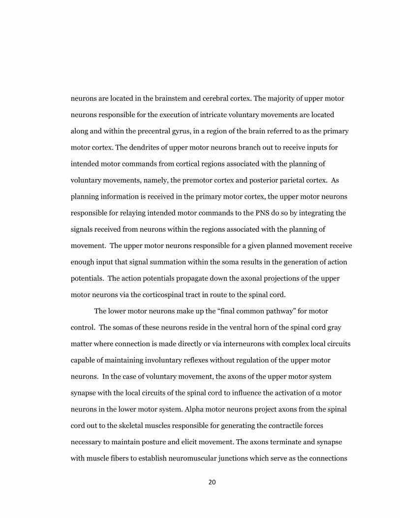
neurons are located in the brainstem and cerebral cortex. The majority of upper motor
neurons responsible for the execution of intricate voluntary movements are located
along and within the precentral gyrus, in a region of the brain referred to as the primary
motor cortex. The dendrites of upper motor neurons branch out to receive inputs for
intended motor commands from cortical regions associated with the planning of
voluntary movements, namely, the premotor cortex and posterior parietal cortex. As
planning information is received in the primary motor cortex, the upper motor neurons
responsible for relaying intended motor commands to the PNS do so by integrating the
signals received from neurons within the regions associated with the planning of
movement. The upper motor neurons responsible for a given planned movement receive
enough input that signal summation within the soma results in the generation of action
potentials. The action potentials propagate down the axonal projections of the upper
motor neurons via the corticospinal tract in route to the spinal cord.
The lower motor neurons make up the “final common pathway” for motor
control. The somas of these neurons reside in the ventral horn of the spinal cord gray
matter where connection is made directly or via interneurons with complex local circuits
capable of maintaining involuntary reflexes without regulation of the upper motor
neurons. In the case of voluntary movement, the axons of the upper motor system
synapse with the local circuits of the spinal cord to influence the activation of α motor
neurons in the lower motor system. Alpha motor neurons project axons from the spinal
cord out to the skeletal muscles responsible for generating the contractile forces
necessary to maintain posture and elicit movement. The axons terminate and synapse
with muscle fibers to establish neuromuscular junctions which serve as the connections

21
Figure 9. Schematic of Motor Pathway to Upper Limb (Joseph 1996, 1999b)
between the nervous and muscular systems. Specific to voluntary movement of the
upper limbs, the lower motor neurons regulating motor control are organized in motor
neuron pools located amongst the C5-T1 levels of the spinal cord. Motor neuron pools
are collections of α motor neurons which innervate the fibers of an individual muscle.
The somas of motor neurons innervating a common muscle are organized into
longitudinal clusters within the gray matter of the ventral horn of the spinal cord. This
high level of organization is maintained as the axons associated with the motor pools
governing movement of the upper limb project outward through the lower four cervical
and first thoracic spinal nerves into the upper arm. The peripheral nerves of the arm
continue to compartmentalize the axons responsible for innervating individual muscles
into fascicles. The fascicles of closely located muscles branch off into smaller nerves as

22
the axonal projections near each muscle’s location in the arm. Finally, individual
fascicles reach their target muscle and the axons within terminate on the fibers of the
innervated muscle.
The organization of the motor pathway within the PNS is retained after
amputation providing anatomically discriminated motor commands for each arm muscle
even if the muscle has been completely removed (Warren, Kellis, & Jacob G. Nieveen,
2016).
Figure 10. Sectional view of spinal nerve showing fascicle organization and connective
tissue layers (2012 Pearson Education, Inc.).

23
3.3 MOTOR UNITS
The population of motor neurons in a motor pool are each responsible for
activating specific fibers of the innervated muscle. The motor neuron, its axon, and the
muscle fibers it innervates collectively form a motor unit. The characteristics of motor
units within a motor pool are often heterogeneous. Motor units are classified into one of
three subtypes depending on their fatigability and twitch force characteristics. These
subtypes include slow twitch non-fatigable S-types, fast twitch fatigue resistant FR-types,
and fast twitch fatigable FF-type motor unit. A large component of the differing
characteristics of motor unit subtypes is the motor neuron’s size which corresponds to
the size and number of muscle fibers it innervates. The variations in size produce trends
in motor unit recruitment order, response time, and force generation according to
Henneman’s size principle. Small motor units are classified as S-type and produce
relatively prolonged low amplitude twitch forces and fire persistently with little fatigue.
Intermediate sized motor units are capable of producing faster, higher amplitude twitch
forces for extended periods of time and are classified as FR-type motor units. The largest
motor units, classified as FF-type, produce fast, high amplitude twitch forces but fatigue
easily after recruitment resulting in an inability to generate high amplitude twitch forces
over prolonged durations.
The recruitment order of a motor pool describes the order in which the motor
units of a pool will surpass their action potential voltage thresholds and become
activated in response to increasing levels of synaptic input. S-type motor units become
activated more easily by a given magnitude of synaptic input due to their motor neuron’s

24
smaller overall surface area which results in a high input resistance. This characteristic
follows Ohm’s Law 𝑉 = 𝐼𝑅 where, for the case of motor neuron activation, 𝐼 corresponds
to the amplitude of current reaching the soma through summation of synaptic inputs, 𝑅
is a motor neuron’s input resistance which has an inverse relationship with motor
neuron size, and 𝑉 is the voltage threshold to elicit action potential generation. A voltage
threshold for motor neuron recruitment is largely consistent across motor neuron types
meaning that as the surface area of motor neurons increase their lower input resistances
necessitate larger synaptic input currents to achieve the voltage threshold needed for
recruitment.
In addition to muscle twitch characteristics, a motor unit’s conduction velocity is
another common means of typing the neurons in a motor pool. Conduction velocity is
measured as the time elapsed between the injection of stimulus current to a motor
neuron and the generation of muscle fiber twitches. When classifying the motor units of
a single motor pool the distance traveled by the stimulus can be considered constant
amongst individual units. A motor neuron’s conduction velocity is governed by the rate
at which action potential propagation occurs in an axon while in route to its innervated
muscle fibers. This rate corresponds to the diameter of an axon and increases as overall
motor neuron size increases. Therefore, motor units with longer response times are
assumed to possess smaller diameter axons as a result of the motor neuron’s reduced
overall size and are classified as S-type motor units. A reduction in response time
corresponds to increasing motor unit size and greater force generation potential which
characterize FR and FF-type motor units (Kandel, 2013).

25
One of the key features enabled by motor unit heterogeneity within a motor pool
is biologically efficient generation of muscle force. Movements requiring only modest
amounts of force can be achieved with lower input stimuli which selectively recruit S-
type motor units capable of maintaining low force levels for extended periods of time.
The magnitude of input stimuli increases as volitional movements increase in force and
velocity spurring the activation of FR and FF-types possessing faster response times and
increased force production. Moderately high forces favor the recruitment of fatigue
resistant FR-type motor units and can be sustained for short periods of time, on the
order of several minutes. More FF-type recruitment is needed as a volitional movement
approaches the force level of a muscle’s maximum voluntary contraction. These efforts
produce rapid, high levels of force but can only be sustained for brief intervals. Further
efficiency of muscle force generation is provided by the ratio of motor unit types in a
motor pool. Muscles responsible for repetitive low force movements are characterized as
possessing higher ratios of S-type motor units while muscles used in the execution of
sporadic high force movements tend to be weighted more towards FF-type motor units.
A common comparison of muscles demonstrating such differences are the soleus and
medial gastrocnemius of the lower leg. Both muscles mediate plantar flexion of the foot
but are preferentially activated depending on the force requirements of the movement
being executed (Moritani, Oddsson, & Thorstensson, 1991). The soleus provides the
muscle force needed to maintain ankle stability while standing and push off the ground
while walking. Neither of these movements require high levels of force but are
sustainable for long periods. The most efficient motor units for achieving these
movements are S-type units which have been observed to comprise the majority of motor

26
units innervating the soleus. In contrast, the medial gastrocnemius is recruited to enable
high force movements such as sprinting or jumping and possesses a greater ratio of FF-
type motor units. This ratio allows the medial gastrocnemius to facilitate these more
explosive movements, but the force generation capacity of the muscle rapidly attenuates
after only a brief period of sustained activity.
The implications of motor unit type and the ratio of types in an individual motor
pool, with respect to neural motor decoding, remain largely unknown. Conceivably,
knowledge of movement types that tend to preferentially activate specific muscles and
these muscles’ motor unit type ratios could be used to aid in the prediction of intended
motor control. High neural activity from motor neurons innervating the soleus would
not necessarily produce force that corresponds with that produced by the medial
gastrocnemius when expressing the same level of neural activity. Insights regarding
such relationships could streamline a decoder’s calibration process of multiple muscles if
precise calibration of a single muscle could be extrapolated based on known relative
force generation characteristics of the additional muscles. Lack of standardized typing
metrics and methods enabling automated typing of multiple motor units at a time means
many muscles remain vaguely characterized. This is especially true for the forearm
muscles responsible for controlling the hand as the large variation in the characteristics
of achievable dexterous movements may require further specialization of motor unit
types that challenge the general trends observed in muscles with more defined roles.
The invasive procedures required to explore these motor unit properties along with
recording techniques that only facilitate the tedious task of characterizing relatively

27
small populations of motor units at a time make this area of study uniquely suited for
exploration with advanced computational modeling.
4. LITERATURE REVIEW: RESEARCH APPROACHES
Efforts to interface with the biological systems responsible for motor commands
and extracting useful data in order to drive prosthetic devices remain numerous with
many research teams approaching the problem with a variety of methods. This overall
problem is often sectioned into several sequential steps to achieve the translation of
biological signals to prosthetic control commands. The first step of any biologically
controlled prosthetic system is the method of data acquisition. Once obtained, the
biological signals typically undergo some form of preprocessing to remove noise
associated with the method used for data collection. After preprocessing, the selection of
the most useful channels is performed by assessing which channels record data reliably
or possess data with high correlation to the target output. The reduced number of
channels are then analyzed to extract useful features which can be as simple as
calculating the rate of motor neuron spiking over a selected duration or measuring the
signal power of an EMG recording. Finally, extracted features are decoded to their target
output by algorithms trained to relate levels of activity to command controls for a
prosthetic device.

28
Figure 11. Schematic representation of upper limb prosthetic control paradigm
(modified from (Silvestro Micera et al., 2010))
4.1 BIOLOGICAL CONTROL SIGNALS
The first consideration for developing a biological interface is the location of the
recording site(s). Broadly, this means selecting between the CNS and PNS.
CNS
Recording from the CNS, i.e. the brain or spinal cord, is a useful and often times
the only source available for patients suffering from spinal cord injury and other
neurodegenerative diseases (Warren et al., 2016). There exist both invasive and non-
invasive means of recording from the motor pathway in the CNS. Non-invasive methods

29
include electroencephalography which records electrical signals from electrodes placed
on the scalp surface and functional near-infrared spectroscopy which can detect changes
in the concentration of oxy- and deoxy-hemoglobin. Hemoglobin dynamics are thought
to be correlated to brain activity in particular regions (Jesunathadas, Klass, Duchateau,
& Enoka, 2012). Each of these methods suffer from low signal to noise ratios as well as
difficulty locating sites to return sensory feedback to users. Invasive methods involve the
implantation of recording electrodes either on the cortical surface or penetrating into the
spinal cord. These methods provide higher quality signals than surface techniques and
have allowed for successful decoding in several studies (Warren et al., 2016),(Sussillo,
Stavisky, Kao, Ryu, & Shenoy, 2016), however, the invasiveness of these techniques and
the complexity of acquired signals limit their use in human subject research.
PNS (EMG)
Amputees with otherwise healthy and intact motor pathways, proximal to their
site of amputation, retain function in the majority of their remaining nerves and muscles.
This allows for many options with respect to interfacing with the PNS. The most
common approach for interfacing with the PNS is via the recording of muscle activity
with EMG. This approach is sensible since muscles generate the force needed for
movement and therefore the signals produced by muscle tissue should closely relate to
the information of motor intent for a prosthetic. Both non-invasive and invasive
methods of recording EMG activity are available with the non-invasive technique of
recording through the skin with surface electrodes being the interface employed by the
majority biological control of prosthetic studies. Ideally, surface EMG allows for

30
recording of muscles that remain within an amputee’s residual stump. Recording from
these sites enable an amputee to control the prosthetic by activating muscles that had
originally been associated with the same movements trying to be accomplished with a
prosthetic. The reality of these systems, however, is that the muscles responsible for
control of hand movements are often lost during amputation. This creates the need for
amputees to activate muscles that are physiologically unrelated to the movement trying
to be performed with their prosthetic. Such a control method is unintuitive, requiring
many hours of training and increased cognitive load (Kutilek et al., 2015).
Invasive EMG recording requires the implantation of electrodes into muscle.
Intramuscular recording provides a more selective biological signal but still does not
mediate the unintuitive nature of EMG control if the original muscles responsible for a
particular movement were lost during amputation. A procedure to mediate the
unintuitive nature of control with EMG interfaces called targeted muscle reinnervation
(TMR) has been developed in recent years (Bowen, Wee, Kalik, & Valerio, 2017;
Cheesborough, Smith, Kuiken, & Dumanian, 2015; O'Shaughnessy et al., 2008;
Renninger, Rocchi, & Kroonen, 2015). This procedure involves locating the residual
nerve endings within an amputee’s stump that had previously innervated and controlled
the movement of muscles removed during amputation. These nerves are then rerouted
to innervate onto more proximal muscles that remain, often muscles within the shoulder
or chest. This procedure is highly invasive but does facilitate more natural control of
prosthetic limbs once the reinnverated sites have healed and begin generating useful
signals. TMR allows the user to execute the same cognitive processes that were needed
to control movements produced by their lost muscles. Rather than the motor pathway
31
transporting the signals of intent to the stump where the muscles no longer remain, the
neural activity activates the reinnverated muscles which can then serve as the recording
sites for EMG collection. The attachment of a large nerve onto a typically smaller region
of donor muscle results in hyperreinnervation where individual muscle fibers can receive
input from multiple axons. This is viewed as beneficial to the goal of accomplishing
reinnervation because it increases the likelihood that a muscle fiber will receive neural
inputs but multiple sources could result in distortion of the observed motor intent. TMR
has been used successfully to enable biological control of prosthetics but the highly
invasive nature of the procedure along with unknowns of the consequences of
mismatched motor neuron and muscle fiber types require further research.
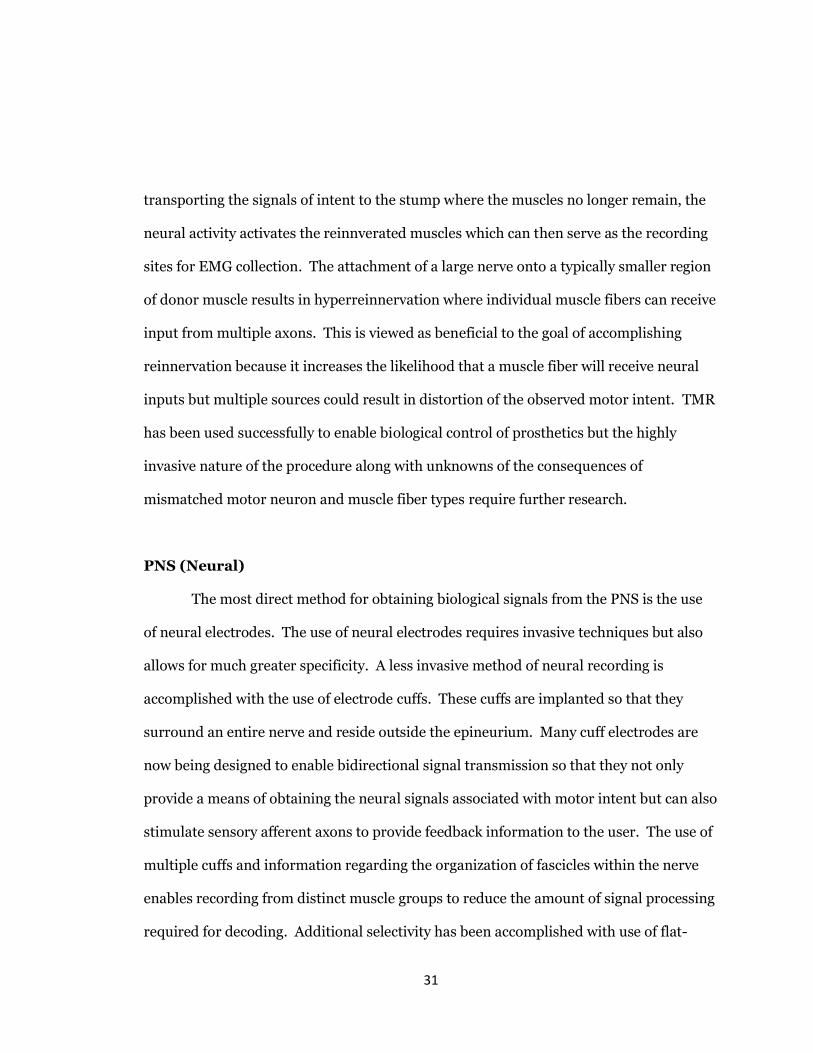
PNS (Neural)
The most direct method for obtaining biological signals from the PNS is the use
of neural electrodes. The use of neural electrodes requires invasive techniques but also
allows for much greater specificity. A less invasive method of neural recording is
accomplished with the use of electrode cuffs. These cuffs are implanted so that they
surround an entire nerve and reside outside the epineurium. Many cuff electrodes are
now being designed to enable bidirectional signal transmission so that they not only
provide a means of obtaining the neural signals associated with motor intent but can also
stimulate sensory afferent axons to provide feedback information to the user. The use of
multiple cuffs and information regarding the organization of fascicles within the nerve
enables recording from distinct muscle groups to reduce the amount of signal processing
required for decoding. Additional selectivity has been accomplished with use of flat-
32
interface nerve electrodes. These electrodes surround the epineurium of a nerve branch,
similar to a cuff electrode, but also compress and flatten the nerve. This increases the
surface area available to record from, exposing fascicles that are otherwise too deep
within a nerve’s cross section to obtain quality signals from extraneural recording
techniques (Sahyouni et al., 2017).
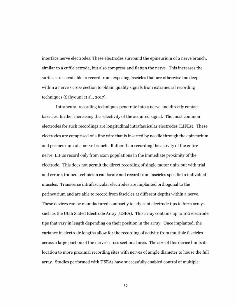
Intraneural recording techniques penetrate into a nerve and directly contact
fascicles, further increasing the selectivity of the acquired signal. The most common
electrodes for such recordings are longitudinal intrafascicular electrodes (LIFEs). These
electrodes are comprised of a fine wire that is inserted by needle through the epineurium
and perineurium of a nerve branch. Rather than recording the activity of the entire
nerve, LIFEs record only from axon populations in the immediate proximity of the
electrode. This does not permit the direct recording of single motor units but with trial
and error a trained technician can locate and record from fascicles specific to individual
muscles. Transverse intrafascicular electrodes are implanted orthogonal to the
perineurium and are able to record from fascicles at different depths within a nerve.
These devices can be manufactured compactly to adjacent electrode tips to form arrays
such as the Utah Slated Electrode Array (USEA). This array contains up to 100 electrode
tips that vary in length depending on their position in the array. Once implanted, the
variance in electrode lengths allow for the recording of activity from multiple fascicles
across a large portion of the nerve’s cross sectional area. The size of this device limits its
location to more proximal recording sites with nerves of ample diameter to house the full
array. Studies performed with USEAs have successfully enabled control of multiple

33
degrees of freedom and sensory feedback to trial subjects (Davis et al., 2016; Wendelken
et al., 2017).
The most advanced methods of intraneural recording exploit the regenerative
capabilities of neurons. Sieve electrodes consist of a perforated disc approximately the
same diameter as the nerve they are to record from. Implantation of the electrode
requires sectioning of the target nerve at the intended recording site. The nerve endings
created by sectioning are inserted at each end of a tubular framework which houses the
sieve electrode. A biocompatible scaffolding, within the framework that houses the
electrode, contains channels that align with the perforations of the electrode. Neural
growth factors seeded within the scaffolding then promote the regrowth of axons toward
the electrode from both nerve endings. If regeneration is successful, the sectioned axons
reconnect and each perforation of the electrode serves as its own recording site. Ideally,
axon connections regenerate with their original counterparts and the axons intersecting
a particular perforation in the electrode disc are common to an individual fascicle. The
ability to record from multiple discriminated fascicles with a single electrode could
enable highly selective signal acquisition possibly reducing the amount of future signal
processing needed. The invasiveness of this electrode and the challenge of consistently
regenerating robust axon connections mean this recording technique is rarely used in
current decoder studies. Continued advancement of regenerative interfaces could
provide future decoders with much more detail of a user’s motor intent.

34
Figure 12. PNS Interfaces in Terms of their Selectivity and Invasiveness (S. Micera et
al., 2011)
The goal of all previously discussed interfacing techniques is to balance the
tradeoff between invasiveness and signal quality/selectively. Early efforts to develop
biological interfaces for prosthetics did not produce the benefits that can be marketed to
today’s research subjects meaning it was much more feasible to recruit subjects to test
with non-invasive surface EMG systems. Invasive intramuscular EMG and LIFE
recordings requiring only a needle for implantation demonstrated the potential benefits
of moving to more invasive interfaces. Although far from ideal control signals, the

35
positive research outcomes of these early studies spurred increased interests from
amputees and funding agencies. This prompted longer term research efforts that
included the recruitment of amputee subjects willing to undergo the surgeries required
to study the control enabled by a variety of invasive biological interfaces. These studies
have not only demonstrated the increased selectivity of invasively recorded signals but
also that these electrodes can remain implanted for many months to years and retain the
ability to record useful signals with minimal harm to neural tissue (Jacobson et al., 1982;
Warren et al., 2016). Intramuscular EMG provides much of the selectively that is gained
from intrafascicular recordings but the challenge of obtaining signal from lost target
muscles requires the increased invasiveness of TMR methods. Therefore, neural
interface methods serve as the ideal conduit to continue increasing the selectively of a
prosthetic’s raw command signals while maintaining moderate levels of invasiveness.
Any effort able to improve a biological interface’s raw signal quality helps reduce the
complexity of later signal processing steps, keeping computation time at a minimum and
allowing for real time prosthetic control.
4.2 SIGNAL PROCESSING AND FEATURE EXTRACTION
Biological signals contain noise artifacts inherent to the instrumentation used for
data collection and the environment within which recording takes place.
Consequentially, the application of filters occurs in the effort to discriminate signals
containing information regarding motor intent from noise. A common practice among
several studies is to continuously sample data at 30 kHz while applying a bandpass filter
with bandwidth ranging from 0.3Hz-7500Hz (Davis et al., 2016; Wendelken et al., 2017).

36
Window averaging may be used to downsample a recorded signal, helping to improve the
computational efficiency of decoding. In some cases, a second highpass filter is applied
to further reduce noise artifacts in the signal. There are various filter characteristics
employed by researchers to denoise both EMG and neural recordings but regardless of
these differences the processes share a common goal. High frequency signal content,
outside the typical range of muscle and neural activity is omitted by the upper limit of
bandpass filtering. Low frequency noise can arise from a variety of sources including
standard 60Hz ambient noise as well as frequencies less than 20Hz caused by motion
artifacts at an electrode’s recoding site or motor units that are inconsistently being
activated by inputs near the unit’s activation threshold. Continuing advancements in
electrode designs aim to reduce motion artifacts and strategic placement of recording
interfaces can help to minimize crosstalk from adjacent motor units. Wireless electrodes
are a feature that fully advanced biologically controlled prosthetic systems should be
expected to possess which are thought may help reduce electrode movement.
The denoised signal is then characterized to a muscle’s rest and active states by
selecting signal features that convey motor intent. A basic approach to feature extraction
is thresholding. This involves the selection of a signal amplitude for which voltage peaks
exceeding the threshold value are considered activity relating to motor intent. A
persistent level of background activity is observed by an electrode even if no motor intent
is being relayed. The signal RMS of a subject’s at rest state can be used to gauge
threshold placement. Thresholds on the order of 5 to 10 times background RMS ensure
that ambiguous signal features are not regarded as motor activity by decoding algorithms
(Warren et al., 2016). Another method for threshold selection involves selecting a

37
percentile of signal amplitudes that serve as a cutoff for describing motor activity such as
arranging the rectified signal by amplitude and categorizing all peaks at 90th percentile
or above as signal derived from motor intent. Simple manual selection for feature
selection is still used for some offline development and testing of decoder techniques.
An advanced feature selection method that attempts to bridge the gap between
EMG and neural recordings is the decomposition of EMG. Intramuscular EMG is more
commonly used due to its intrinsic selectively but within the last decade surface EMG
decomposition techniques have become available (Farina, Holobar, Merletti, & Enoka,
2010). The EMG characteristics of individual MU action potentials produce unique
waveforms that can be discriminated with wavelet analysis. MU decomposition software
such as EMGLAB optimally analyze intramuscular EMG recordings in 3 to 5 second
segments. This resolution enables the waveforms of singular voltage peaks to be
characterized and compared to other peaks within the sample segment. Regularly
repeating distinct waveforms are judged by the software to have originated from an
individual MU and a template of the MU spike characteristics is saved so that the
remainder of the recording can be searched. A quality signal can be automatically
decomposed by EMGLAB into several MU spike trains. The automated result typically
contains errors such as missed MU spikes that must be manually corrected. Manual
analysis of the signal can also often identify additional MUs that were overlooked during
automated processing (McGill, Lateva, & Marateb, 2005). While largely performed
offline, recent efforts have advanced this technique towards use with real-time
applications (Glaser, Holobar, & Damjan Zazula, 2013; Siqueira Júnior & Soares, 2015).
However, decomposition is limited in its ability to identify individual MU firings in

38
signals produced by moderate and high motor inputs. Greater levels of activity increase
the likelihood that spikes originating from multiple MUs will superposition, resulting in
a more complex waveform that is challenging to resolve. The ability of this technique to
acquire individual MU firings from what would otherwise be considered population data
is useful for offline study of the abilities of more selective decoding methods without
requiring invasive electrode interfaces to obtain highly selective biological signals.
Once the features that identify motor intent are established, interfaces comprised
of multiple electrodes or recording channels are assessed to judge which channels
routinely contain activity closely corresponding to the dynamics of executed movements.
This process also commonly occurs offline but the transition to automated channel
selection has begun with statistical methods such as principal component analysis
having been employed to automate channel selection. Characterized channels mean the
system can then weight channels with high information content to improve decoder
accuracy or exclude channels with signals containing little relevant information to
improve computational efficiency. As the field progresses towards achieving restoration
of intuitive naturalistic prosthetic control, adaptive automated feature extraction
methods capable of real-time operation are being adopted. These automated methods
seek to characterize the user’s biological signals during a calibration session that takes
place when an amputee receives their prosthetic device. Calibration involves the
amputee executing a series of movements expected by researchers to produce the signal
features necessary to train the prosthetic’s decoding algorithms.
Calibration or training of proportional control schemes establish the activity
range for each of the prosthetic’s controllable degrees of freedom. This range is

39
established by prompting the amputee to gradually increase their effort to set a
minimum level of activity to elicit movement. This is followed by a maximal effort or
maximum voluntary contraction to set the upper bounds of the user’s activation range.
Many studies have performed calibration with the aid of virtual training paradigms
(Burck, Bigelow, & Harshbarger, 2011; Soares, Andrade, Lamounier, & Carrijo, 2003;
Wendelken et al., 2017). These can be as simple as a cursor that increases and decreases
its y-axis value as it scrolls across a monitor, with the user instructed to produce motor
activity corresponding to the cursor’s present value. Virtual training environments allow
the user to control a simulated prosthetic such as the MuJoCo hand. Training tasks
require the generation of motor activity that results in a prosthetic under user control to
match the orientation of a virtual phantom hand orientation. This can again be
performed with single degrees of freedoms to establish proportional control by
displaying a target that changes location along the particular movement’s range of
motion. Training of pattern recognition control schemes involves the execution of the
complex grip patterns. The changes in signal content among all useful channels during
execution of each grip are then characterized to enable classification of signal features so
that the current movement is selected during future operation.

40
4.3 DECODING AND CLASSIFICATION
Extensive reviews of decoding techniques for biological prosthetic control are
regularly published (Hong, Aziz, & Ghafoor, 2018; Silvestro Micera et al., 2010; Warren
et al., 2016). Published works have implemented decoding systems that extract motor
commands from a variety of both time domain and frequency domain features.
Decoders for EMG signals commonly base their predictions on the amplitude of the
obtained signal as this measure is assumed to linearly correlate with force of contraction
(Hahne et al., 2014; Roberts & Gabaldon, 2008; Sussillo et al., 2016). Mathematical
methods, largely rooted in statistics, are presented with biological signals of known
characteristics to obtain signal averages over time. These averages are then matched
with corresponding movement commands or are used to train the coefficient parameters
of decoding metrics. A widely used statistical decoding method is Kalman filtering which
is trained on the expected value and variance of extracted signals. As the filter receives
new data samples, it accounts for variance and rather than using the raw sample value
makes an estimate for the activity at that time based on the previous activity that has
occurred (Welch & Bishop, 2006). Statistical methods are also employed to decode
motor commands from neural recordings. The most common feature analyzed from
neural recordings is the unit or pool’s firing rate, calculated by counting the number of
action potentials observed over a set duration (Kapelner, Negro, & Aszmann, 2018).
Pattern recognition systems classify motor intent by selecting a trained movement with
signal averages most closely corresponding to the user’s present motor activity. The
primary challenge for all statistical decoding methods is lack of adaptability. Variations
in the motor intent describing a particular movement are caused by intrinsic nervous

41
system changes. As a result, the vast majority of non-adaptive decoders demonstrate
little in the way of objective superiority regardless of their complexity. Efforts to correct
this limitation are being made through use of adaptive statistical classifiers such as
neural networks (Silvestro Micera et al., 2010). Another avenue of mediation is the
development of increasingly selective signal acquisition as decoders presently operate
with population activity due to lack of reliable methods able to obtain individual unit
recordings.
5. THE DEVELOPMENT OF AN AUTO-CALIBRATING NEURAL MOTOR DECODER
5.1 PROBLEM STATEMENT
Myoelectric systems face drawbacks inherent to using EMG for signal acquisition.
Surface EMG systems are ideal as non-invasive, low cost options but obtaining signal to
noise ratios suitable for more advanced control systems can be challenging. Surface
EMG also must contend with the extent of limb loss a user has. Users other than those
with distal amputations of the hand lose many of the muscles that facilitate movements
of the hand and wrist, leaving no site for EMG recording. Targeted muscle reinnervation
allows for nerves, previously targeting removed muscles, to be reattached at new muscle
sites, often in the pectoral muscles. This invasive procedure results in the generation of
EMG activity corresponding to muscles of the forearm and hand in the retargeted
muscle. The activity is susceptible to crosstalk from the native EMG activity of the
reinnervated muscle as well as possible effects of MN type/muscle fiber type
mismatches.

42
The decoding of neural recordings allows for a direct link between the cortical
activities associated with a prosthetic user’s intended movement and the manipulation of
a prosthetic device. Recording from sources within the PNS eases the task of data
preprocessing by exploiting the body’s natural information sorting pathways (spinal cord
and peripheral nerves) which remain after amputation of the limb. The use of these
pathways leaves open the possibility of obtaining highly specific MN firing content
corresponding to the activation of individual muscles. The reconstruction of the user’s
intentions from individual muscles to determine the movement resulting from their
cumulative effects has the potential to provide the more nuanced movements that can be
lost when recording and decoding co-agonist/antagonist muscle pairs. Such decoders
are certainly capable of restoring function however the quality of resultant movements
continue to be somewhat rigid and non-naturalistic. These more nuanced movements
remain elusive but would be expected from a prosthetic system able to fully replicate the
functions of a natural limb.
Over the last 15 years several studies have shown that intrafascicular and cuff
electrode recordings can successfully restore motor control for a limited number of
degrees of freedom (Davis et al., 2016; Dhillon, Lawrence, Hutchinson, & Horch, 2004;
S. Micera et al., 2011; Wendelken et al., 2017). Our group’s research has noted a
limitation of past and current neural motor decoders is the frequent fine tuning of
trained parameters required to maintain accurate prosthetic control. The variations that
necessitate such adjustments are of biological origin. Natural variability in the neural
activity supplied to a motor pool by descending monoaminergic axons of the spinal cord
has the end result of governing a motor pool’s neuroexcitability state. The excitability of

43
the motor pool, in turn, governs the amplification in firing response provided by the
calcium mediated dendritic persistent inward current (Elbasiouny, Bennett, &
Mushahwar, 2006). A major cause for the required fine tuning of decoder parameters
are therefore the small changes to a motor pool’s firing response that will be encountered
if an amputee’s neuroexcitability state fluctuates between decoder training and testing.
The development of advanced decoder algorithms which can self-adjust to changes in
neuroexcitability would decrease the frequency of manual parameter tuning and
facilitate the functioning of increasingly robust neural motor decoder systems.
Development and testing of motor decoder algorithms with physical data is
limited by many unknowns, adding further complexity to the already difficult task of
motor decoding. The system input (motor intent) and output (movement) can be
characterized with a fair amount of certainty in cases where experimenters can prompt
and receive feedback from human subjects. Anatomical knowledge also allows for
derivation of the physiological path an elicited motor intent signal will take in route to its
target muscle. However, intrinsic characteristics of the motor pathway’s physiological
components introduce output variability even under conditions when the motor input
remains unchanged. This results in algorithms trained with physical data having to
contend with output fluctuations that occur from physiological changes. These changes
are of course not completely immeasurable but assessing the state of all motor pathway
components would vastly increase the complexity and invasiveness required for
biological control systems for prosthetics. Inability to directly monitor the modulation of
each component and how these changes affect transmission among components,
requires decoders to account for irregularities that manifest within what is essentially a

44
black box. Biological signals also contain considerable amounts of miscellaneous signal
features that are regarded as noise and must be filtered out before decoding. This
processing distorts the raw signal to some extent. The current tradeoff between doing
light filtering to minimize distortion or more aggressive filtering to discriminate usable
signal features from noise presents the possibility that non-biological features or
distorted biological features are present during decoder training. While these
uncertainties must be handled by advanced decoding methods that are at their end stage
in development, removal of unknowns during the development process enables selective
troubleshooting and identification of biological features that may be of aid to decoders.
5.2 WHY NEURAL MODELING?
The use of a computational motor pool model as a platform for decoder
development enables assessment of the effects of system components with much greater
precision. The system input is no longer a human subject’s best effort to produce
prompted motor commands but instead an input constructed by the experimenter. This
enables the testing of an infinite set of input characteristics whether it be the movement
type, speed, or time course. The characteristics of the motor pool model is also
adjustable allowing for testing of the decoder on a variety of physiological states. A
motor pool’s size, MN type ratios, and excitability are all suggested to effect decoder
performance, but the employment of a model allows for gradual adjustment of each
parameter, individually, meaning the source of decoder inaccuracies is can be revealed
by observing which parameters resolve the errors. The highly characterized pool input
serves as an ideal control for assessing decoder performance. The differences in

45
movement generated by the decoded motor intent and original input provides the degree
to which the decoders output varies from an ideal output. Finally, all preliminary
aspects of decoder development and testing are established within a noise free
environment with the experimenter provided the option of inserting gradually increasing
amounts of artificial noise as the capabilities of the motor decoder are advanced.
5.3 METHODS
Acquisition of Firing Data
The conductance of synapses inserted along the dendrites of MNs in the MU pool
model are adjusted to simulate an input stimulus to the pool (Figure 13-B, G). A current
clamp is inserted at the soma of each MN to record membrane potential deflection
caused by the simulated post synaptic potentials. The membrane potential output is
sampled at 40 kHz (delta T of 0.025ms between samples) which is the default sample
rate of NEURON. Post analysis of the membrane potential recordings applies a
threshold of 30mV above resting membrane potential (resting membrane potential set to
-70mV) to identify the firing instances of MNs within the pool. Timestamps of all
instances for which a cell’s membrane voltage exceeds the threshold level are saved and
inserted to a binary data matrix. Each row of this matrix corresponds to a sampled time
instance. The first two columns contain the timestamps sampled at 40 kHz and the
delivered synaptic input current to the pool for a given sample time. All remaining
columns report the firing instances of individual MNs, such that, if a MN fired at a given
sampled time the corresponding row instance for that column in the data matrix will
have a value of 1. For any other time point during which a cell is not firing, the data

46
matrix contains a value of 0. This allows the spike count (Figure 13-F) for a sampled
instance or range of instances (i.e. window averaging) to be calculated by summing all
the columns of the data matrix, excluding the time and synaptic input columns.
Figure 13. Overview of decoder testing paradigm. A. Schematic of testing system.
Synaptic conductance channels are adjusted to deliver a net input to motor pool. Net
input activates motor pool and elicits action potential (spike) generation in recruited
motor neurons. Motor neuron spikes from individual cells are aggregated to calculate
firing rate of motor pool. Motor pool firing rate is decoded to produce an estimate the
degree of movement generated from pool firing content. Movement commands are sent
to MuJoCo to produce visual representation of decoder performance. B. Motor pool is

47
made up of a combination of slow type (blue), fast fatigue resistant (purple), and fast
fatigable cells (red). Ratio of cell populations is obtained from medial gastrocnemius
muscle of cat. C. Degree of error from actual of decoder predicted MuJoCo position for
decoding of full pool (gray), S-type (blue), FR-type (purple), and FF-type (red). D. The
movement profile of decoded MuJoCo commands are compared to the actual (black)
movement profile expected to result from the simulated activation input. E. Smoothed
and windowed aggregate firing rate of motor pool. F. Motor pool action potentials (gray)
along with partitioned spike trains for each cell type S (blue), FR (purple), and FF (red).
Highlights recruitment order and persistent firing characteristics of S and FR cell types.
G. Profile of synaptic input simulated to activate motor pool. Input increases at 4nA/s
to a peak level of 10nA then returns to 0nA input at -4nA/s.
Scrolling Window Averaging
Windowing initializes with the system creating a 50ms window, all windows
thereafter advance with an update interval of 10ms such that the first 40ms of the new
window is comprised of the last 40ms of the previous window. The 10ms update
segment contains the most recently recorded pool firing data.
This feature provides the smoothing effects of a 50ms window average while
avoiding a delay equal to the full window length. The system must only wait for the data
associated with the update segment to be collected before its next calculation can
proceed. This reduces the latency associated with data acquisition from 50ms, as would
be the case with discrete windows, to 10ms for scrolling windows.

48
Brown’s Linear Exponential Smoothing
Brown’s method for exponential smoothing is applied to reduce the variation in
spike count among successive time windows (Hansun, 2016). The smoothed spike count
𝑦𝑡 is modelled by a linear regression equation as the sum of intercept 𝑏0 and slope 𝑏1
which are estimates of the spike count’s level and trend, respectively. Estimates of 𝑏0
and 𝑏1 are calculated by maintaining two exponentially smoothed parameters 𝑥′𝑡 and 𝑥"𝑡.
The first exponentially smoothed parameter 𝑥′𝑡 is a weighted sum of the present spike
count 𝑥𝑡 and the previous window’s smoothed parameter 𝑥′𝑡−1. The second
exponentially smoothed parameter 𝑥"𝑡 is the weighted sum of the present first
exponentially smoothed parameter 𝑥′𝑡 and the previous window’s second exponentially
smoothed parameter 𝑥"𝑡−1. These parameters’ recursive origins allow the single
weighting parameter (α=0.08) to apply an exponentially decreasing weight to past spike
count observations.
𝑥′𝑡 = 𝛼𝑥𝑡 + (1 − 𝛼)𝑥′𝑡−1
𝑥"𝑡 = 𝛼𝑥′𝑡 + (1 − 𝛼)𝑥"𝑡−1
𝑏0 = 2𝑥′𝑡 − 𝑥"𝑡
𝑏1 =𝛼
(1 − 𝛼)(𝑥′𝑡 − 𝑥"𝑡)
𝑦𝑡 = 𝑏0 + 𝑏1
This results in a smoothed value that is the weighted average of the most recent spike
count window and many previous spike count windows while avoiding the

49
computational expense of maintaining a vector of saved previous spike count
observations. The smoothed spike count and fixed window size of 50ms are then used to
convert to a firing rate value in Hertz.
Decoder Calibration
The decoder assumes two firing phases during which the pool’s firing rate
responds linearly to changes of synaptic input.
𝑆𝑦𝑛𝑎𝑝𝑡𝑖𝑐 𝐼𝑛𝑝𝑢𝑡(𝑛𝐴) = (𝑔 ∗ 𝑅𝑇𝐸 + 𝑦𝑡 − 𝑀𝐹𝑅)/𝑔
𝑔 =∆ 𝐹𝑖𝑟𝑖𝑛𝑔 𝑅𝑎𝑡𝑒
∆ 𝑆𝑦𝑛𝑎𝑝𝑡𝑖𝑐 𝐼𝑛𝑝𝑢𝑡
Where g is the F/I relationship for the firing phase, RTE is the input level at onset of
firing, MFR is the firing rate at onset of firing, and 𝑦𝑡 is the current smoothed firing rate
(Fuglevand, Winter, & Patla, 1993). Calibration of these parameters is determined by
assessing the aggregate firing output response of the pool to a triangular ramp inputs
(Figure 13-E). Ramp activation rates of 2nA/s, 4nA/s, and 6nA/s are required for full
calibration of the auto-calibrating decoder. Each firing phase is calibrated with a
particular portion of the firing response. The secondary phase parameters are set
relative to the onset and initial acceleration in pool firing which corresponds to the
aggregate firing occurring from 1500-2000ms in Figure 13-E. The region of the firing
response where this acceleration is seen to decrease while the activation rate of the ramp
remains constant is treated as the pool’s transition to tertiary firing. Calibration of the

50
tertiary phase is then set using the firing response from this transition region to the peak
level of firing/activation, aggregate firing occurring from 2000-3500ms in Figure 13-E.
Decoder Testing and Error Assessment
The decoder’s performance is tested and assessed by comparing the resultant
movement of MuJoCo physics simulator’s Lukehand prosthetic model when controlled
by the actual input to the pool and the decoder predicted input (Figure 13-D). A
conversion scheme was established to relate the input magnitude in nanoamperes (nA)
to the prosthetic model’s finger position angle (degrees). The peak synaptic input of
10nA corresponds to 60 degrees of finger flexion, with all other values from zero to the
peak maintaining a linear relationship, given the linearity of the input stimulus. In order
to obtain the movement which would result from the actual input, the decoder is altered
so that rather than sending a prediction of the synaptic input to MuJoCo, the true value
of synaptically injected current for the given time instance of simulation is sent to
command the prosthetic. After this command executes, the prosthetic’s joint angle is
recorded and stored to a vector. This vector then serves as the reference for comparison
of any subsequent decoding efforts of firing output in response to the particular synaptic
input profile.
Two performance metrics were used to quantitatively assess the accuracy of the
motor decoder compared to the movement generated by the actual input. Pearson’s
linear correlation coefficient provides a general assessment of decode performance by
judging if the prosthetic is being driven in the intended direction of movement. The

51
outcome of this statistical test is a value between 0 and 1, where values approaching 1
signify a high correlation between the direction of motion of decoder’s output and the
actual intended movement. Pearson’s linear correlation coefficient does not provide an
assessment of the error in magnitude of motion and is therefore used in conjunction with
a normalized root mean square error (NRMSE). The NRMSE accumulates and produces
an average of the residuals of the decoder’s output in comparison to the prosthetic’s
position during the actual intended movement. This value is then normalized over the
range of movement to produce a percent error of the decoder’s performance.
Correlation Coefficient (CC)
𝐶𝐶 =∑ (𝑧𝑘 − 𝑧̅)(�̂�𝑘 − �̂�̅)𝑁
𝑘=1
√∑ (𝑧𝑘 − 𝑧̅)𝑁𝑘=1
2∑ (�̂�𝑘 − �̂�̅)
2𝑁𝑘=1
where 𝑧𝑘 is the actual hand position read by MuJoco, 𝑧̅ is the mean of the actual hand
position, �̂�𝑘 is the decoded hand position read by MuJoco and �̂�̅ is the mean of the
decoded hand position.
Normalized Root Mean Square Error (NRMSE)
𝑅𝑀𝑆𝐸 = √1
𝑁∑(�̂�𝑘 − 𝑧𝑘)2
𝑁
𝑘=1
𝑁𝑅𝑀𝑆𝐸 = 𝑅𝑀𝑆𝐸
max (𝑧𝑘) − min(𝑧𝑘)

52
5.4 RESULTS
Cell Type testing
The 51 motor neuron homogeneous pool model described in (Allen, Elbasiouny
2017) was synaptically injected at a rate of 4nA/s to a peak level of 10nA, after which the
level of activation was reduced at a rate of -4nA/s until measured input at the somas
returned to 0nA, Figure 13-G. This input profile is of sufficient magnitude to recruit
100% of S and FR-type MNs and 80% of FF-type MNs which constitutes 90%
recruitment of the full pool. The decoder was calibrated with respect to the aggregate
firing output of the recruited motor neurons (see Methods for detail). As expected, the
decoder’s ability to predict the profile of activation for which it is calibrated is quite good,
see Figure 13-D (gray trace). Due to the variation in cell type ratios seen in different
muscles, as well as the plasticity of expressed cell characteristics that occurs after injury
or long periods of non-use (Raineteau & Schwab, 2001), it is of interest to determine how
well the full pool calibration performs on particular cell type populations. The firing
output from individual cell type populations was partitioned from the output of the full
pool, Figure 13-F. A scaling factor was then calculated for each cell type via the equation:
𝑠𝑐𝑎𝑙𝑖𝑛𝑔 𝑓𝑎𝑐𝑡𝑜𝑟 =𝑡𝑜𝑡𝑎𝑙 𝑠𝑝𝑖𝑘𝑒𝑠 𝑜𝑓 𝑐𝑒𝑙𝑙 𝑡𝑦𝑝𝑒 𝑝𝑎𝑟𝑡𝑖𝑡𝑖𝑜𝑛
𝑡𝑜𝑡𝑎𝑙 𝑠𝑝𝑖𝑘𝑒𝑠 𝑜𝑓 𝑝𝑜𝑜𝑙
The factor is necessary to account for the reduced firing content of a partition relative to
the firing output of the pool. This factor was then applied to the decoder’s calibrated
parameters with the exception of the recruitment threshold which remains unchanged
regardless of the overall firing content. The firing outputs of each cell type were fed to
the decoder separately and the resulting MuJoCo movement was recorded for
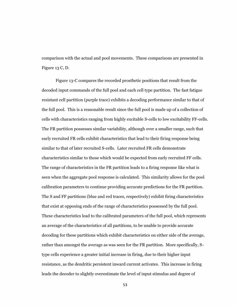
53
comparison with the actual and pool movements. These comparisons are presented in
Figure 13 C, D.
Figure 13-C compares the recorded prosthetic positions that result from the
decoded input commands of the full pool and each cell type partition. The fast fatigue
resistant cell partition (purple trace) exhibits a decoding performance similar to that of
the full pool. This is a reasonable result since the full pool is made up of a collection of
cells with characteristics ranging from highly excitable S-cells to low excitability FF-cells.
The FR partition possesses similar variability, although over a smaller range, such that
early recruited FR cells exhibit characteristics that lead to their firing response being
similar to that of later recruited S-cells. Later recruited FR cells demonstrate
characteristics similar to those which would be expected from early recruited FF cells.
The range of characteristics in the FR partition leads to a firing response like what is
seen when the aggregate pool response is calculated. This similarity allows for the pool
calibration parameters to continue providing accurate predictions for the FR partition.
The S and FF partitions (blue and red traces, respectively) exhibit firing characteristics
that exist at opposing ends of the range of characteristics possessed by the full pool.
These characteristics lead to the calibrated parameters of the full pool, which represents
an average of the characteristics of all partitions, to be unable to provide accurate
decoding for these partitions which exhibit characteristics on either side of the average,
rather than amongst the average as was seen for the FR partition. More specifically, S-
type cells experience a greater initial increase in firing, due to their higher input
resistance, as the dendritic persistent inward current activates. This increase in firing
leads the decoder to slightly overestimate the level of input stimulus and degree of

54
movement after the onset of firing until ~2000ms. Once the PIC has saturated, S-type
cells respond with a lower firing rate-current relationship, meaning that as the input
stimulus continues to increase, S cells respond with only modest increases in firing rate,
relative to the other cell types. The lesser increase in firing content results in the
underestimation of the input magnitude and degree of movement. The FF partition’s
firing response to the input is characterized by a lesser response to the PIC at onset of
firing, later followed by an increase in firing content facilitated by FF type cells’ shorter
AHP. The shorter AHP allows FF cells to continue to increase their firing rate as input
continues to increase. This increased firing, relative to the pool average, results in an
overestimation of intended movement. These relationships are further supported by
tests in which the decoder was calibrated to the firing content of each partitioned cell
type and then tested of the firing content of the full pool (Figure 14). The decoder
calibrated to S-type firing severely overestimates the intended degree of motion when
decoding the full pool’s firing content (Figure 14-D). This is due to calibrated parameters
which lead the decoder to expect the modest increases in firing content to continued
synaptic input increases, shown by S-type MNs during tertiary phase firing. An FR-type
calibrated decoder was able to provide suitable decoding of the pool’s aggregate firing
content (Figure 14-E). While an FF calibrated decoder resulted in underestimation of
the intended degree of movement due to the decoder expecting the pool to behave with
the high firing rate to input stimulus tertiary relationship possessed by FF-type cells
(Figure 14-F).

55
Figure 14. Performance of cell type calibrated decoders tested on full pool. A. S-type
calibrated decoder tested on S-type firing partition. B. FR-type calibrated decoder
tested on FR-type firing partition. C. FF-type calibrated decoder tested on FF-type firing
partition. D. S-type calibrated decoder tested on aggregate pool firing. Calibration leads
decoder to expect only modest increases of firing rate in tertiary phase. Additional firing
rate increases of FR and FF type cause decoder to overestimate intended degree of
movement. E. FR-type calibrated decoder tested on aggregate pool firing. Firing rate
profile of FR-type partition results in an F/I response similar to that of the aggregate
pool firing which allows for accurate decoding. Slight imbalance of S and FF type
contributions lead to the aggregate firing content containing slightly more AP instances
than FR-type partition. This increased firing content results in the slight overestimation
of movement. F. FF-type calibrated decoder tested on aggregate pool firing. Pool’s

56
lower rate of firing relative to FF partition results in underestimation of movement along
with a delayed switch to tertiary phase decoding.
Single Decoder Speed Testing
The decoder calibrated to the pool’s aggregate firing response to a 4nA/s medium
synaptic activation rate, which elicits opening and closing of the hand in approximately 5
seconds or about 2.5 seconds of movement in each direction, was tested on two
aggregate firing output datasets (Figure 15). One dataset, classified as a slow activation
rate of input was obtained by stimulating the MU pool model at 1nA/s to a peak of 10nA,
before descending to 0nA at -1nA/s (Figure 15-A, slow). This activation rate causes the
hand to open and close in 9 seconds for each direction making the total time the hand is
in motion approximately 18 seconds. A second dataset modelled a case during which a
fast rate of activation was being applied to the MU pool. The fast activation rate firing
data was obtained by stimulating the MU pool at an activation rate of 7nA/s, again to a
peak stimulus level of 10nA, before decreasing at -7nA/s to 0nA (Figure 15-A, fast). The
fast inputs generate flexion and extension for approximately 1.5 seconds leading to a
total movement time of about 3 seconds. The “actual” MuJoCo outputs for these
datasets were obtained, as previously described, for comparison with the decoded input
estimates (see Methods). The decoder’s performance in predicting the input profile of
the slow activation paradigm in presented in Figure 15-B, D. When the motor pool was
activated at 1nA/s, firing of the highest excitable cells began at a lower stimulus level
than when activated at 4nA/s. This change in the onset of firing results in a decoded

57
trace which begins eliciting movement in MuJoCo prior to the onset of movement for the
actual case (Figure 15-D). The increasing contribution of the PIC can be seen to saturate
at approximately 3000ms, however, the decoder remains in secondary gain mode until
approximately 5000ms, at which point the aggregate firing of the pool surpasses the
calibrated threshold and the decoder’s F/I gain mode switches to tertiary. Once the
decoder had begun using the calibrated parameters for tertiary gain mode, performance
remained satisfactory for the remainder of the test (Figure 15-B). The results of testing
with the fast input demonstrate an opposite effect when the rate of pool activation is
greater than that for which the decoder was calibrated (Figure 15-C, E). The onset of
pool firing occurred at a recruitment threshold greater than that seen for the 4nA/s
synaptic input rate. This resulted in MuJoCo receiving delayed commands to begin
movement at approximately 1500ms (Figure 15-E). The threshold for switching between
secondary and tertiary gain modes was reached at ~1750ms but gradual increase in PIC
magnitude continued until approximately 1900ms. This discrepancy resulted in an
abrupt change from underestimation of the actual output to overestimation during the
1750-1900ms time interval. Once the PIC had saturated, tertiary gain mode decoding
progressed with an error not exceeding ~10 degrees from actual Lukehand model
position (Figure 15-C). The quantitative error assessment for the single speed decoder
provided in Table 1 shows that while the decoder can accurately predict movement at the
intermediate speed for which it was calibrated, performance drop-offs occur when the
decoder encounters movements being performed at speeds slower or faster than the
decoder’s training movement.

58
Table 1. Performance assessment of single speed decoder
Tested Input rate Correlation Coefficient NRMSE Slow (1nAs) 0.991663 0.046716 Intermediate (4nAs) 0.997284 0.035786 Fast (7nAs) 0.973050 0.087387 Average 0.987332 0.056630
Two Speed Decoder
In the effort to increase the accuracy of the decoded MuJoCo movement profiles,
two single speed decoders were calibrated to the slow (2nA/s) and fast (6nA/s) activation
rates. If implemented to operate in unison, such an arrangement would allow the
decoder to only be challenged with predicting rates within 2nA/s of a calibrated rate.
The results of these tests demonstrate a reduction in error as activation rates become
closer to that of the calibrated rates (Figure 16, Table 2). The error present in these tests
correspond with the error of the single speed decoder testing, in that for each test
condition the decoder was challenged with decoding the movement resulting from an
activation rate greater than or less than that for which it was calibrated (comparing
Figures 15 and 16). The error in the two single speed decoder tests occur due to the same
phenomenon that were responsible for the error in the single speed decoder test. The
magnitude of error in single speed decoder test was greater since the decoder is
attempting to predict for activation rates deviating 3nA/s from its calibrated value versus
the 2nA/s deviation faced by the two-speed decoder when predicting a 4nA/s input. The
error that manifests when decoding pool firing stimulated at an activation rate deviating
2nA/s from the calibrated rate is of sufficient magnitude to hinder accurate movement

59
decoding, as observed by the lower correlation coefficient and higher NRMSE (Table 2)
resulting from the testing of the 2 and 6nA/s calibrated decoders’ attempts to decode an
intermediate 4nA/s movement. The error in predicted movement can be seen to
decrease to negligible magnitudes when the decoder is challenged with decoding for
activation rates that only deviate by 1nA/s from the decoder calibrated rate (Figure 16-A,
F). The decoder is capable of predicting these inputs with almost the same degree of
error present when the decoder was tested on the activation rates for which it was
calibrated (Figure 16-B, E).
Table 2. Performance assessment of two-speed decoder.
Calibrated Input Rate
Tested Input Rate Correlation Coefficient
NRMSE
2nAs
1nAs 0.996193 0.046111 2nAs 0.994483 0.052779 4nAs 0.983805 0.070157
6nAs
4nAs 0.978230 0.058873 6nAs 0.992828 0.037198 7nAs 0.992521 0.053079
Average 0.989677 0.053033

60
Three Speed Decoder
The original medium speed decoder (4nA/s) was included with the 2nA/s and
6nA/s decoders to produce a series of three, single speed decoders which allow
prediction to occur with calibrated parameters that do not deviate from the tested input’s
activation rate by more than 1nA/s (Figure 17). The lower and higher than calibrated
input tests possess the characteristic errors that occur when decoding at activation rates
deviating from a decoder’s calibrated rate. However, these errors have been minimized
to an extent which allows for interpolation between calibration speed parameters when
the single decoders are paired to work in unison. The improvement in performance by
the three-speed decoder is evident when comparing the average correlation coefficients
and NRMSEs in Tables 2 & 3.
Table 3. Performance assessment of three-speed decoder.
Calibrated Input Rate
Tested Input Rate Correlation Coefficient
NRMSE
2nAs
1nAs 0.996193 0.046111 2nAs 0.994483 0.052779 3nAs 0.989764 0.062991
4nAs
3nAs 0.995957 0.039878 4nAs 0.997284 0.035786 5nAs 0.993629 0.046991
6nAs
5nAs 0.987776 0.044269 6nAs 0.992828 0.037198 7nAs 0.992521 0.053079
Average 0.99022 0.046565

61
Figure 15. Results for decoder calibrated to medium speed input tested on slow and fast
activation paradigms. A. Profiles of training (medium) input and test (slow/fast) inputs.
B. Residual error of decoder tested on slow input. Initial error due to earlier activation
of motor pool. C. Residual error of decoder tested on fast input, caused by later
activation of pool and faster firing rate increase to tertiary threshold. D. Slow input
comparison of actual MuJoCo movement (black) to decoded MuJoCo movement (gray).
E. Fast input comparison of actual MuJoCo movement (black) to decoded MuJoCo
movement (gray).

62
Figure 16. Two speed decoder (2 & 6nA/s) tested across range of activation rates (1-
7nA/s). All figures include actual MuJoCo movement (black) compared with decoded
MuJoCo movement (gray) A. Decoder calibrated to 2nA/s input tested on a 1nA/s
activation profile. B. Decoder calibrated to 2nA/s input tested on a 2nA/s activation
profile. C. Decoder calibrated to 2nA/s input tested on a 4nA/s activation profile. D.
Decoder calibrated to 6nA/s input tested on a 4nA/s activation profile. E. Decoder
calibrated to 6nA/s input tested on a 6nA/s activation profile. F. Decoder calibrated to
6nA/s input tested on a 7nA/s activation profile.
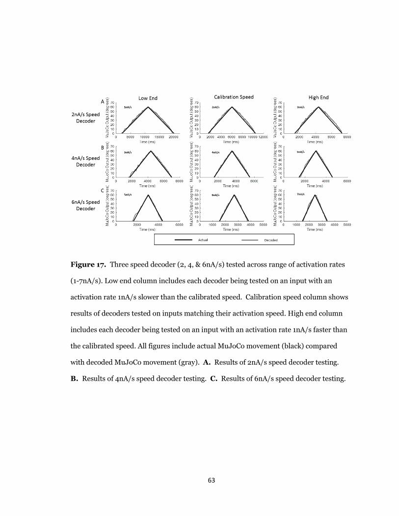
63
Figure 17. Three speed decoder (2, 4, & 6nA/s) tested across range of activation rates
(1-7nA/s). Low end column includes each decoder being tested on an input with an
activation rate 1nA/s slower than the calibrated speed. Calibration speed column shows
results of decoders tested on inputs matching their activation speed. High end column
includes each decoder being tested on an input with an activation rate 1nA/s faster than
the calibrated speed. All figures include actual MuJoCo movement (black) compared
with decoded MuJoCo movement (gray). A. Results of 2nA/s speed decoder testing.
B. Results of 4nA/s speed decoder testing. C. Results of 6nA/s speed decoder testing.

64
Auto-Calibrating Decoder
The three-speed decoder was modified to automatically detect the pool activation
speed and switch to the correct algorithm parameters. Results of the auto-calibrating
three-speed decoder showed a greatly improved decoding performance at all testing
speeds, as compared to the single-speed and two-speed motor decoders presented above.
Notably, the auto-calibration was highly efficient, and the optimized auto-calibrating
decoder still maintained real-time (<10ms) scrolling update windows.
This decoder was tested with synaptic inputs representing movements at
different ranges of motion, speed, and type (figures 18, 19, and 20, respectively).
Testing the auto-calibrating decoder with ramp inputs of multiple degrees
corresponds to the execution of flexion and extension of the hand to different positions
within the hand’s range of motion. Figure 18-A shows the decoder’s performance when
the MuJoCo hand is closed to 60 degrees before opening, which represents 2/3 of its full
90 degrees range of motion. Movements to ½ and ¼ of the hand’s range of motion are
shown in panels B and C of Figure 18, respectively, in order to test the auto-calibrating
decoder’s performance at lower degrees of movement. Performance results for the auto-
calibrating decoder’s range of motion test demonstrates its ability to provide excellent
estimates of the MuJoCo hands intended position at one-half and two-thirds degree of
flexion. Flexion to one-fourth degree of closure resulted in a slightly reduced but
acceptable level of performance due to the decoder’s calibration being referenced with
respect to the MuJoCo hand’s fully flexed, 90 degrees range of motion.

65
Table 4. Performance of auto-calibrating decoder across range of motion.
Range of motion Correlation Coefficient NRMSE 1/4 0.9831 0.0498 1/2 0.9971 0.0264 2/3 0.9973 0.0292
Figure 18. Testing of the auto-calibrating three-speed decoder at multiple degrees of
flexion/extension within a 90-degree range of motion. A. Performance of auto-
calibrating decoder for flexion and extension across 2/3 range of motion B. Performance
of auto-calibrating decoder for flexion and extension across 1/2 range of motion C.
Performance of auto-calibrating decoder for flexion and extension across 1/4 range of
motion

66
The auto-calibrating decoder was tested with movements of different speeds to
demonstrate its ability to provide proportional control of movement velocity.
Performance of the decoder at slow, intermediate, and fast speeds (figure 19) was tested
by ramp inputs to 60 degrees closure at 1, 4, and 7nA/s activation rates. At 1nA/s,
flexion and extension is slowly completed over 18 seconds, Figure 19-A. A 4nA/s
activation rate allows the same degree of flexion and extension to occur over 6 seconds,
Figure 19-B. The fastest activation of 7nA/s mediates flexion and extension in just 3
seconds, Figure 19-C. The decoder successfully predicts the movement speed of each
input with only minor overestimation of the 4nA/s input, Table 5.
Table 5. Performance of auto-calibrating decoder for different movement speeds.
Speed Correlation Coefficient NRMSE Slow 0.9973 0.0293 Intermediate 0.9950 0.0556 Fast 0.9982 0.0253

67
Figure 19. Testing of the auto-calibrating three-speed decoder with flexion/extension
movements of different speed. A. Performance of auto-calibrating decoder for flexion
and extension to 2/3 range of motion over 18 seconds B. Performance of auto-
calibrating decoder for flexion and extension to 2/3 range of motion over 6 seconds C.
Performance of auto-calibrating decoder for flexion and extension to 2/3 range of
motion over 3 seconds

68
The grasping of objects requires the decoder to be able to maintain its flexed position
rather than simply opening and closing in succession. Figure 20 demonstrates the auto-
calibrating decoder’s ability to control the MuJoCo hand’s position for each of these
movement types. Both movements are accurately decoded with NRMSEs of under 3%
(Table 6).
Table 6. Performance of auto-calibrating decoder for different movement types.
Movement Type Correlation Coefficient NRMSE Ramp 0.9973 0.0292 Ramp & Hold 0.9989 0.0180

69
Figure 20. Testing of the auto-calibrating three-speed decoder with multiple
movements A. Performance of auto-calibrating decoder for flexion and extension
movement B. Performance of auto-calibrating decoder for grasp and hold movement.

70
Variable-speed Input Test
To further examine the developed decoder with inputs that reflect a more
practical prosthetic use, we tested the auto-calibrating three-speed decoder with a
variable input of changing activation rate (figure 21). This input mimics a situation in
which the amputee performs the onset and offset of a grasping movement slowly but
increases speed mid-movement to quickly close and open their hand. Under these
conditions, the auto-calibrating decoder should switch parameters in real time as it
detects the changing activation rate. This input begins activating the pool at 2nA/s after
a one second, zero input period. The 2nA/s activation continues for two seconds, at
which point the input rate increases to 6nA/s for one second to result in a peak stimulus
level of 10nA. The input profile then reverses to result in a symmetric, duel-speed ramp
(Figure 21-A). Figure 21-B shows the rate of change in pool firing rate that was used to
estimate the activation speed (from the dFR value) and its direction (positive value for
increasing input and negative value for decreasing inputs). Although the variable input
made a large switch in speed (from the lowest to the highest activation sub-ranges
skipping the intermediate sub-range), the decoder still auto-switched and correctly
estimated the activation speed in real-time. Note that it was able to decode the variable
speed input accurately on both the ascending and descending phases of input and
replicated the dual-speed ramp (Figure 21-C) with small error in MuJoCo position
(Figure 21-D). The auto-switching decoder accurately predicts the direction of
movement as evidenced by a 0.995 correlation coefficient and maintains a generally
accurate degree of movement with a NRMSE of 0.056 (Table 7). The highest error in
MuJoCo hand movement did not exceed 10° from its expected joint position. These
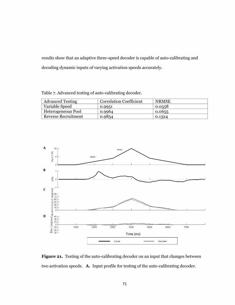
71
results show that an adaptive three-speed decoder is capable of auto-calibrating and
decoding dynamic inputs of varying activation speeds accurately.
Table 7. Advanced testing of auto-calibrating decoder.
Advanced Testing Correlation Coefficient NRMSE Variable Speed 0.9951 0.0558 Heterogeneous Pool 0.9964 0.0655 Reverse Recruitment 0.9854 0.1324
Figure 21. Testing of the auto-calibrating decoder on an input that changes between
two activation speeds. A. Input profile for testing of the auto-calibrating decoder.

72
Synaptic input increases at 2nA/s for 2000ms after which increasing to 6nA/s for
1000ms to reach a peak activation of 10nA. The input then decreases at -6nA/s for
1000ms and -2nA/s for 2000ms to return to an activation level of zero. B. Rate of
change in firing rate causes by duel speed input. This measure is used to facilitate the
speed switching procedures of the auto-calibrating decoder. C. Comparison of actual
MuJoCo movement (black) resulting from duel speed input to the decoded MuJoCo
movement (gray). D. Residual error of the auto-calibrating decoder tested on duel speed
input.
Heterogeneous Pool Test
Biological heterogeneity in the electrical properties of individual MNs expands
the recruitment range of MNs within each sub-type, resulting in high variability in
aggregate pool spikes (Allen & Elbasiouny 2018). Therefore, to further test the
robustness of the auto-calibrating three-speed decoder, we used a heterogeneous MU
pool model developed by Allen & Elbasiouny (2018) to generate firing output in response
to an increasing and decreasing ramp input. This heterogeneous MU pool model has a
larger MN pool (153 MNs) and largely mimics the variability in MN cellular properties
observed experimentally (figure 22-A). Such biological variability has a strong impact on
the firing behaviors of MU pools (Allen & Elbasiouny 2017) and would be expected to be
encountered in human subjects. We therefore tested the auto-calibrating three-speed
decoder with a heterogeneous pool spike train (Figure 22) to determine the robustness of
its output. Figure 22-B shows that the auto-calibrating three-speed decoder was able to

73
decode the input accurately despite the large variability in pool spikes. The largest errors
were observed at the onset and offset of pool firing due to the expanded recruitment and
de-recruitment ranges. The error decreases as greater percentage of the cells activate and
results in good performance overall with a correlation coefficient of 0.996 and NRMSE
of 0.065 (Table 7).
Figure 22. Testing of auto-calibrating decoder with the firing output of a heterogeneous
MU pool. A. Comparison of physiological activation characteristics to activation
characteristics of heterogeneous MU pool. B. Auto-calibrating decoder performance
decoding output of heterogeneous MU pool.

74
Reverse Recruitment Pool Test
While the orderly recruitment of MNs by size (S before FR before FF –
Henneman size principle) is heavily emphasized in literature. Mixed and reversed
recruitment of MNs has been observed in animals and humans including a number of
cortical inputs to spinal MNs that have been shown to favor reverse MN recruitment
(Binder, Robinson, & Powers, 1998; Powers, Robinson, Konodi, & Binder, 1993;
Westcott, Powers, Robinson, & Binder, 1995). Thus, we examined the robustness of
performance of the auto-calibrating three-speed decoder in a situation of reversed
recruitment. Reverse recruitment was produced by activating the MN pool model with a
non-uniform synaptic input of higher magnitude to FF-type cells > FR-type > S-type
cells (Figure 23-A), effectively reversing pool recruitment so that FF-type cells fire first,
then FR, then S (Figure 23-B). The decoder’s resultant output is shown in Figure 23-C.
The output is initially very close, with only a slight underestimation. This is seemingly
the result of the interplay of the S-type cells contributing less firing, while the FF-types
contribute more, during the onset of firing, as compared to activation from a uniform
input. These changed contributions of each cell type effectively cancel each other,
resulting in accurate decoding of this portion of the input. As the decoder output enters
tertiary mode (sustained PIC activation), a gradually increasing overestimation error can
be seen to occur, which levels out along the decreasing input ramp. This error occurs for
two reasons: 1) An increase in the pool’s aggregate firing when FF-types are stimulated at
such a high activation rate and magnitude, and 2) the more gradual shift to tertiary
phase because the S-types, which are most affected by PICs, are slow to reach tertiary
levels in this recruitment mode. This increase in firing also sends the auto-calibrator

75
into higher speed parameters than would occur for a uniform 4.6nA/s triangular input,
which represents the single input rate profile that results from weighting the non-
uniform activation provided to each cell type. While the decoder auto-calibrated as if the
pool were experiencing uniform activation, resulting in an error that persists throughout
the tertiary phase, the general profile of the input is still reasonably predicted as
evidenced by the 0.985 correlation coefficient (i.e. decoder output has high correlation to
stimulus profile reported in Table 7. The error in the estimate of input magnitude is
largely due to the variations in aggregate firing produced by the reversal of recruitment
order which increases the NRMSE to 0.132. Since our decoder is calibrated with respect
to a pool’s aggregate firing, it is postulated that as long as a motor pool demonstrates a
consistent recruitment order, any variation in the pool’s aggregate firing from that which
is produced during recruitment by the size principle would be accounted for during
calibration of the decoder to a given motor pool.
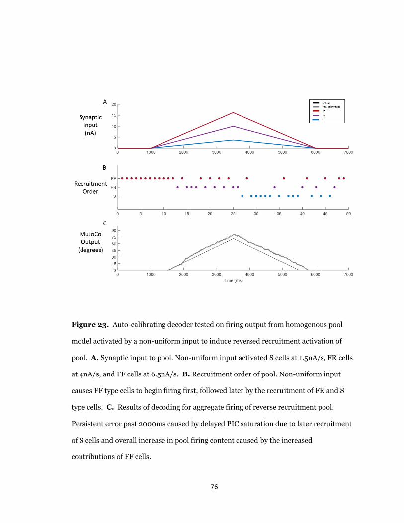
76
Figure 23. Auto-calibrating decoder tested on firing output from homogenous pool
model activated by a non-uniform input to induce reversed recruitment activation of
pool. A. Synaptic input to pool. Non-uniform input activated S cells at 1.5nA/s, FR cells
at 4nA/s, and FF cells at 6.5nA/s. B. Recruitment order of pool. Non-uniform input
causes FF type cells to begin firing first, followed later by the recruitment of FR and S
type cells. C. Results of decoding for aggregate firing of reverse recruitment pool.
Persistent error past 2000ms caused by delayed PIC saturation due to later recruitment
of S cells and overall increase in pool firing content caused by the increased
contributions of FF cells.

77
5.5 DISCUSSION
Summary of the work
EMG recordings have long been used in computationally-efficient decoders and
have restored some measure of function to amputees via affordable prostheses. As
computing power, electrode sophistication, and knowledge about the
electrophysiological properties of the nervous system have increased, the field has begun
to explore ENG recordings in the hopes of extracting far more detailed motor
information, as well as restoring sensory percepts. These achievements could allow full
exploitation of the capabilities of state-of-the-art prostheses, which provide more
sophisticated motions than decoders can currently drive. Thus, the first major goal of our
work was to develop a real-time, neurophysiologically accurate motor decoder with the
assistance of a highly-realistic computational platform for modeling motor pool firing
behaviors with a validated and unprecedented level of accuracy (Allen and Elbasiouny,
2017). The second major goal of this work was to rigorously assess the decoder in this
same environment – which allows for full control of parameters and “clear-box” insight
into every aspect of the decoding process. We accomplished this by testing the decoder
within a variety of situations designed to represent the array of potential movements and
biological heterogeneity which would be expected during actual use by human patients.
A series of optimizations resulted in the development of an auto-calibrating three-speed
capability for this decoder. After this improvement, we were able to demonstrate a very
high level of accurate decoding by comparing the decoder’s output into a virtual
prosthetic hand with the output of the original synaptic input. These rigorous tests

78
validate that this decoder operates in real time (<10ms updates using 50ms smoothed
scrolling averaging windows) and produces highly accurate prosthesis inputs (metrics)
across a wide variety of biologically heterogeneous situations.
Novel aspects of the work include the accurate neurophysiological basis of the
decoder’s development, such that it is reliable across heterogeneous settings; the use of
this same platform, including its “clear-box” approach, for optimization and rigorous
assessment of this decoder’s performance; and the development of auto-calibration
capabilities.
The significance of the work is that this decoder has the potential to advance the
performance of ENG-based prosthesis controls, given its reliability of operations within
biological heterogeneity, so that users can more consistently and accurately produce
their intended movements.
The Computational Platform
Linear solutions have been used to describe the input/output functions of both
EMG and ENG signals. The limitations of such solutions have increased interest in non-
linear solutions that might improve accuracy of decoding neural inputs to their
associated limb movements. The assumption that neural activity maintains a linear
relationship to the generation of muscle force to achieve intended movements is an
oversimplification that fails to account for intrinsic changes to neural firing rates. In
addition to the voltage gated sodium and potassium channels that provide for

79
propagation of ionic currents along a neuron’s cell membrane, are voltage gated calcium
channels capable of amplifying the currents generated by postsynaptic potentials. As a
postsynaptic potential propagates through the dendritic tree in route to the soma, these
calcium channels activate and provide a persistent inward current (PIC) which mediates
the amplification of the original synaptic input. The onset of this PIC results in a brief
interval of rapid increase in firing rate and therefore disrupts the otherwise linearly
proportional relationship between synaptic input and MN discharge rate. This firing rate
increase occurs as the voltage dependent channels transition from their resting to active
state. Once the channels reach their full conductance, the PIC provides a consistent level
of amplification resulting in a return to linearly proportional changes in MN firing rate in
response to changes in synaptic input. The MU pool model used in development of our
decoder possesses the physiological components responsible for this non-linearity in
firing response so that these features are accounted for during decoder training. The
period of firing which occurs at the onset of PIC amplification maintains a distinct linear
relationship with an increased proportion of MN discharge to synaptic input. Our
decoder is trained to account for these distinct firing relationships by switching between
the calibrated parameters that describe each. With the decoder expecting an abrupt
acceleration in firing rate at the onset of motor pool activation due to the activation of
channels mediating the PIC, the intended degree of movement can be produced without
the increased firing content resulting in an overestimation of the user’s intent.

80
Optimization of Decoder Speeds and Self-Calibration
The goal of the motor decoder algorithm is to estimate the magnitude of the
synaptic input (i.e., excitation level) to the MNs from the train of pool spikes (decoder
input). Estimated excitation level (decoder output) was used to drive the opening and
closing movements of the simulated MuJoCo hand (i.e., prosthesis input). The moving
bin averaged incoming spike data at 50ms, yet latency was only 10ms, leading to effective
averaging and a fast update rate. Initially, it was examined whether a motor decoder
algorithm calibrated to synaptic input of a single speed of 4nA/s would function with
equal accuracy at other speeds (1nA/s to 7nA/s). Results demonstrate that good
performance of a single-speed motor decoder algorithm at its calibration speed does not
extend well to other speeds.
We first expanded the single-speed motor decoder described above into a two-
speed motor decoder. The activation speed range of the prosthetic hand (1nA/s to
7nA/s) was then split into two sub-ranges covered by two decoder algorithms: One
calibrated to a speed of 2nA/s to cover the 1nA/s-4nA/s sub-range (figure 16 A-C), and
another calibrated to a speed of 6nA/s to cover the 4nA/s-7nA/s sub-range (figure 16 D-
F) results indicate that our motor decoder algorithms do not perform well when tested
with activation speeds > 1nA/s away from their calibration speeds.
We further expanded our motor decoder framework to split the activation speed
range of the prosthetic hand into three sub-ranges a low-speed algorithm calibrated to a
speed of 2nA/s covered the activation sub-range between 1nA/s-3nA/s (figure 17-A). A
middle-speed algorithm calibrated to a speed of 4nA/s covered the activation sub-range
between 3nA/s-5nA/s (figure 17-B). Finally, a high-speed algorithm calibrated to a speed

81
of 6nA/s covered the activation sub-range between 5nA/s-7nA/s (figure 17-C). Each
decoder algorithm covers an activation speed no more than 1nA/s away from its
calibration speed on either end greatly improved decoding performance at all testing
speeds.
Notably, the auto-calibration was highly efficient, and the optimized three-speed
decoder still maintained real-time (<10ms) scrolling update windows.
Performance Comparison
Contemporary decoders seeking to restore motor control by recording from
residual peripheral nerves report maximum performance metrics in the range of 85-95%
position accuracy and correlation coefficient R>0.9 when comparing intended
movement profiles to decoded movement profiles. This level of success is typically
achieved during control of minimal DOFs and after many subject trials. These effects to
performance would be expected due to the increased complexity of movements utilizing
multiple DOFs and an increase in subject performance as they become familiar with the
experimental tasks. It is during the early stages of subject trials that manual tuning is
also performed to maximize a prosthetic device’s operation to the subject’s intention.
The auto-calibrating decoder we developed meets or exceeds the performance abilities of
previously developed decoders. The decoder successfully decodes a range of single speed
movements along with variable speed movement with approximately 5% NRMSE and
correlation of R=0.99. Challenging the decoder with the addition of MU pool variability
or changes to recruitment order decrease the performance accuracy but only modestly.
Pool variability is handled well resulting in only a slight decrease in performance while a

82
reversed recruitment order results in an increase of the NRMSE to 14%. These results
demonstrate that even when presented with firing activity modified from what our
decoder was trained with it is able to perform decodes with accuracy in line with the
maximum performance of available neural motor control algorithms.
Limitations
Tests performed using our motor pool model demonstrate the overall flexibility
of biologically inspired control systems. Under conditions that result in reversed
recruitment orders diverging from the typically assumed recruitment by size principle,
the decoder is still capable of producing reasonably accurate movement estimates with
total error not exceeding 15%. This is achieved through the use of aggregate firing
content to characterize the input/output functions of the motor pool. Since our decoder
is calibrated with respect to a pool’s aggregate firing, it is postulated that as long as a
motor pool demonstrates a consistent recruitment order, any variation in the pool’s
aggregate firing from that which is produced during recruitment by the size principle
would be accounted for during calibration of the decoder to a given motor pool.
Dependence on such an assumption demonstrates a limitation of our developed
decoder. In its current form the decoder cannot adapt to changes in recruitment order
during real time operation. This problem is less severe with respect to any gradual
changes that occur due to MN adaptation post amputation if recalibration occurs
frequently which would allow the decoder to be manually adjusted to account for slight
changes to pool recruitment. The significance of this limitation becomes evident when
more rapid changes to recruitment order are considered. Recruitment order has been

83
observed to change based on the characteristics of the contraction or movement being
performed. While slow to moderate speed isometric contractions tend to elicit pool
activation that follows orderly recruitment, ballistic and eccentric contractions have been
seen to produce instances of mixed or reverse recruitment. Successive or prolonged
activation of a motor pool can also produce periods of mixed and reverse recruitment as
the nervous system tries to most efficiently maintain an intended level of contraction
while contending with the onset of MN and muscle fatigue. These changes to
recruitment order can therefore be expected to be encountered during daily use making
rectification of this limitation via recalibration unfeasible. We believe true rectification
of this limitation would be accomplished by improving the selectivity of recorded signals
used to quantify the firing activity of a motor pool. Specifically, selectivity allowing
individual MUs to be typed and tracked, either by direct recording or decomposition,
would allow a decoder to readily assess which types of MUs are the first to be recruited
for a given contraction or if type characteristics of individual MNs are shifting over time.
This idea extends to our testing of the decoder on MN firing partitioned by cell
type. Decoding was best for the FR type cell partition as this type possesses the average
firing characteristics across all the cells in the pool. The system training pertaining to
the average characteristics of the pool would not be exclusive to healthy motor pools.
The changes in MN type ratios that occur due to some degenerative diseases and spinal
cord injury would shift the average firing characteristics of the pool away from the FR
type, if greater amounts of S or FF type cells are being lost. The use of aggregate firing
content to train the system means the decoder is not dependent on the average pool
characteristics corresponding to a given type of cell. Rather as the motor pool

84
progressively changes, as long as these changes remain gradual the system could shift
with regular calibration to account for changing MN type ratios.
The developed motor decoder also lacks its sensory encoder counterpart. User
trials of advanced prosthetics have shown that open-loop control systems (i.e. only
providing motor control) limit an amputee’s ability to perform the basic daily tasks these
systems seek to restore. The lack of sensory feedback requires the amputee to visually
attend to the movements they intend to perform and presents great challenge during
activities where a user must regulate the grasping force being exerted on an object.
Completion of a truly closed-loop neural control system requires an appropriate level of
stimulation being provided to the amputee’s sensory afferent MNs. The sensory
afferents then relay the information describing the position and force exertion of the
prosthetic so that a user can cognitively attend to task performance without the need for
visual feedback. In addition to ascending tracts leading to the brain, afferent MNs also
mediate local neural networks within the spinal cord. This allows the afferent MNs to
directly, or indirectly via interneurons, synapse to and modulate the activity of efferent
MNs responsible for regulating muscle force. These spinal networks enable reflexive
movements and help the neuromuscular system maintain contraction levels within a
range that serves as a safeguard against damage from overexertion. The effects of the
additional input from sensory MNs on the firing activity received by the motor decoder
was outside the scope of the current research but such activity could conceivably reduce
the performance of the motor decoder.

85
6. CONCLUSION
The developed motor decoder demonstrates the advantage of utilizing motor
neuron physiology to improve the estimation of motor intent from neural recordings for
prosthetic control. Many complex statistical motor decoders are able to accurately
predict motor intent but only so long as the motor system’s activation characteristics
remain unaltered. Adaptive decoding methods continue to improve in their ability to
adjust to variable input/output characteristics, but purely statistical methods possess
minimal insight regarding the intrinsic neural mechanisms responsible for these
changes. They therefore must observe relatively large segments of data to register these
changes causing them to struggle to operate in real time. The employment of neural
models for decoder development provides a means of isolating these mechanisms so that
their individual effects on signal variability can be characterized. The true test for
decoders trained with simulated data is of course the transition to decoding human
subject data. While there still exists a gap in the quality of data able to be physically
obtained compared to that which can be generated in regulated computational
environments, increasingly selective neural interfaces could significantly improve the
amounts of physiological information available for motor intent signal characterization.
The pairing of this information with simpler but more computationally efficient adaptive
statistical methods may then allow for the accuracy and response times needed to
facilitate long lasting biological control of prosthetic devices. The biologically inspired
control our decoder employs presents a framework to advance neural decoders beyond
their current largely statistical basis. This framework could resolve some of the more
computationally expensive procedures employed by current decoders and produce
86
response times that edge closer to real time. This decoder also opens the door for the
development of biological/statistical hybrid control schemes which incorporate the
advantages of each decoding method.

87
7. REFERENCES
Allen, J. M., & Elbasiouny, S. M. (2018). The effects of model composition design choices on high-fidelity simulations of motoneuron recruitment and firing behaviors. J Neural Eng, 15(3), 036024. doi: 10.1088/1741-2552/aa9db5
Behrend, C., Reizner, W., Marchessault, J. A., & Hammert, W. C. (2011). Update on advances in upper extremity prosthetics. J Hand Surg Am, 36(10), 1711-1717. doi: 10.1016/j.jhsa.2011.07.024
Biddiss, E. A., & Chau, T. T. (2007). Upper limb prosthesis use and abandonment: a survey of the last 25 years. Prosthet Orthot Int, 31(3), 236-257. doi: 10.1080/03093640600994581
Binder, M. D., Robinson, F. R., & Powers, R. K. (1998). Distribution of effective synaptic currents in cat triceps surae motoneurons. VI. Contralateral pyramidal tract. J Neurophysiol, 80(1), 241-248. doi: 10.1152/jn.1998.80.1.241
Bowen, J. B., Wee, C. E., Kalik, J., & Valerio, I. L. (2017). Targeted Muscle Reinnervation to Improve Pain, Prosthetic Tolerance, and Bioprosthetic Outcomes in the Amputee. Adv Wound Care (New Rochelle), 6(8), 261-267. doi: 10.1089/wound.2016.0717
Burck, J. M., Bigelow, J. D., & Harshbarger, S. D. (2011). Revolutionizing Prosthetics: Systems Engineering Challenges and Opportunities. JOHNS HOPKINS APL TECHNICAL DIGEST, 30(3), 186.
Cheesborough, J. E., Smith, L. H., Kuiken, T. A., & Dumanian, G. A. (2015). Targeted muscle reinnervation and advanced prosthetic arms. Semin Plast Surg, 29(1), 62-72. doi: 10.1055/s-0035-1544166
Cordella, F., Ciancio, A. L., Sacchetti, R., Davalli, A., Cutti, A. G., Guglielmelli, E., & Zollo, L. (2016). Literature Review on Needs of Upper Limb Prosthesis Users. Front Neurosci, 10, 209. doi: 10.3389/fnins.2016.00209
Davis, T. S., Wark, H. A., Hutchinson, D. T., Warren, D. J., O'Neill, K., Scheinblum, T., . . . Greger, B. (2016). Restoring motor control and sensory feedback in people with upper extremity amputations using arrays of 96 microelectrodes implanted in the median and ulnar nerves. J Neural Eng, 13(3), 036001. doi: 10.1088/1741-2560/13/3/036001
DeGol, J., Akhtar, A., Manja, B., & Bretl, T. (2016). Automatic Grasp Selection using a Camera in a Hand Prosthesis. Conference proceedings : Annual International Conference of the IEEE Engineering in Medicine and Biology Society IEEE Engineering in Medicine and Biology Society Annual Conference, 2016, 431-434. doi: 10.1109/EMBC.2016.7590732

88
Dhillon, G. S., Lawrence, S. M., Hutchinson, D. T., & Horch, K. W. (2004). Residual function in peripheral nerve stumps of amputees: implications for neural control of artificial limbs. J Hand Surg Am, 29(4), 605-615; discussion 616-608. doi: 10.1016/j.jhsa.2004.02.006
Elbasiouny, S. M., Bennett, D. J., & Mushahwar, V. K. (2006). Simulation of Ca2+ persistent inward currents in spinal motoneurones: mode of activation and integration of synaptic inputs. J Physiol, 570(Pt 2), 355-374. doi: 10.1113/jphysiol.2005.099119
Farina, D., Holobar, A., Merletti, R., & Enoka, R. M. (2010). Decoding the neural drive to muscles from the surface electromyogram. Clin Neurophysiol, 121(10), 1616-1623. doi: 10.1016/j.clinph.2009.10.040
Fuglevand, A. J., Winter, D. A., & Patla, A. E. (1993). Models of recruitment and rate coding organization in motor-unit pools. J Neurophysiol, 70(6), 2470-2488.
Geethanjali, P. (2016). Myoelectric control of prosthetic hands: state-of-the-art review. Med Devices (Auckl), 9, 247-255. doi: 10.2147/MDER.S91102
Glaser, V., Holobar, A., & Damjan Zazula. (2013). Real-Time Motor Unit Identification From High-Density Surface EMG. IEEE TRANSACTIONS ON NEURAL SYSTEMS AND REHABILITATION ENGINEERING, 21(6), 949-958.
Hahne, J. M., Bießmann, F., Jiang, N., Rehbaum, H., Farina, D., Meinecke, F. C., . . . Parra, L. C. (2014). Linear and Nonlinear Regression Techniques for Simultaneous and Proportional Myoelectric Control. IEEE TRANSACTIONS ON NEURAL SYSTEMS AND REHABILITATION ENGINEERING, 22(2), 269-279.
Hansun, S. (2016). A New Approach of Brown's Double Expnential Smoothing Method in Time Series Analysis. Balkan Journal of Electrical & Computer Engineering, 4(2), 75-78. doi: 10.17694/bajece.14351
Henneman, E. (1985). The size-principle: a deterministic output emerges from a set of probabilistic connections. J Exp Biol, 115, 105-112.
Hong, K. S., Aziz, N., & Ghafoor, U. (2018). Motor-commands decoding using peripheral nerve signals: a review. J Neural Eng, 15(3), 031004. doi: 10.1088/1741-2552/aab383
Jacobson, S. C., Knutti, D. F., & Johnson, R. T. (1982). Development of the Utah Artificial Arm. IEEE TRANSACTIONS ON BIOMEDICAL ENGINEERING,, BME-29(4), 249-268.
Jesunathadas, M., Klass, M., Duchateau, J., & Enoka, R. M. (2012). Discharge properties of motor units during steady isometric contractions performed with the dorsiflexor muscles. J Appl Physiol (1985), 112(11), 1897-1905. doi: 10.1152/japplphysiol.01372.2011

89
Johannes, M. S., Bigelow, J. D., Burck, J. M., & Harshbarger, S. D. (2011). An Overview of the Developmental Process for the Modular Prosthetic Limb. JOHNS HOPKINS APL TECHNICAL DIGEST, 30(3), 207-216.
Kandel, E. R. (2013). Principles of neural science (5th ed ed.). New York: McGraw-Hill Medical.
Kapelner, T., Negro, F., & Aszmann, O. (2018). Decoding Motor Unit Activity From Forearm Muscles: Perspectives for Myoelectric Control. IEEE TRANSACTIONS ON NEURAL SYSTEMS AND REHABILITATION ENGINEERING, 26(1), 244-251.
Kutilek, P., Mares, J., Hybl, J., Socha, V., Schlenker, J., & Stefek, A. (2015). Myoelectric arm using artificial neural networks to reduce cognitive load of the user. Neural Computing and Applications, 28(2), 419-427. doi: 10.1007/s00521-015-2074-x
McGill, K. C., Lateva, Z. C., & Marateb, H. R. (2005). EMGLAB: an interactive EMG decomposition program. J Neurosci Methods, 149(2), 121-133. doi: 10.1016/j.jneumeth.2005.05.015
Micera, S., Carpaneto, J., & Raspopovic, S. (2010). Control of Hand Prostheses Using Peripheral Information. IEEE REVIEWS IN BIOMEDICAL ENGINEERING,, 3, 48-68.
Micera, S., Rossini, P. M., Rigosa, J., Citi, L., Carpaneto, J., Raspopovic, S., . . . Dario, P. (2011). Decoding of grasping information from neural signals recorded using peripheral intrafascicular interfaces. J Neuroeng Rehabil, 8, 53. doi: 10.1186/1743-0003-8-53
Moritani, T., Oddsson, L., & Thorstensson, A. (1991). Activation patterns of the soleus and gastrocnemius muscles during different motor tasks. J Electromyogr Kinesiol, 1(2), 81-88. doi: 10.1016/1050-6411(91)90001-L
O'Shaughnessy, K. D., Dumanian, G. A., Lipschutz, R. D., Miller, L. A., Stubblefield, K., & Kuiken, T. A. (2008). Targeted reinnervation to improve prosthesis control in transhumeral amputees. A report of three cases. J Bone Joint Surg Am, 90(2), 393-400. doi: 10.2106/JBJS.G.00268
Powers, R. K., Robinson, F. R., Konodi, M. A., & Binder, M. D. (1993). Distribution of rubrospinal synaptic input to cat triceps surae motoneurons. J Neurophysiol, 70(4), 1460-1468. doi: 10.1152/jn.1993.70.4.1460
Raineteau, O., & Schwab, M. E. (2001). Plasticity of Motor Systems after Incomplete Spinal Cord Injury. Nature Reviews Neuroscience, 2.
Renninger, C. H., Rocchi, V. J., & Kroonen, L. T. (2015). Targeted Muscle Reinnervation of the Brachium: An Anatomic Study of Musculocutaneous and Radial Nerve Motor Points Relative to Proximal Landmarks. J Hand Surg Am, 40(11), 2223-2228. doi: 10.1016/j.jhsa.2015.07.030

90
Resnik, L., Klinger, S. L., & Etter, K. (2014). The DEKA Arm: its features, functionality, and evolution during the Veterans Affairs Study to optimize the DEKA Arm. Prosthet Orthot Int, 38(6), 492-504. doi: 10.1177/0309364613506913
Resnik, L., Klinger, S. L., Etter, K., & Fantini, C. (2014). Controlling a multi-degree of freedom upper limb prosthesis using foot controls: user experience. Disabil Rehabil Assist Technol, 9(4), 318-329. doi: 10.3109/17483107.2013.822024
Resnik, L., Meucci, M. R., Lieberman-Klinger, S., Fantini, C., Kelty, D. L., Disla, R., & Sasson, N. (2012). Advanced upper limb prosthetic devices: implications for upper limb prosthetic rehabilitation. Arch Phys Med Rehabil, 93(4), 710-717. doi: 10.1016/j.apmr.2011.11.010
Roberts, T. J., & Gabaldon, A. M. (2008). Interpreting muscle function from EMG: lessons learned from direct measurements of muscle force. Integrative and Comparative Biology, 48(2), 312-320.
Sahyouni, R., Mahmoodi, A., Chen, J. W., Chang, D. T., Moshtaghi, O., Djalilian, H. R., & Lin, H. W. (2017). Interfacing with the nervous system: a review of current bioelectric technologies. Neurosurg Rev. doi: 10.1007/s10143-017-0920-2
Siqueira Júnior, A. L. D., & Soares, A. B. (2015). A novel method for EMG decomposition based on matched filters. Research on Biomedical Engineering, 31(1), 44-55. doi: 10.1590/2446-4740.0643
Soares, A., Andrade, A., Lamounier, E., & Carrijo, R. (2003). The Development of a Virtual Myoelectric Prosthesis Controlled by an EMG Pattern Recognition System Based on Neural Networks. Journal of Intelligent Information Systems, 21(2), 127-141.
Sussillo, D., Stavisky, S. D., Kao, J. C., Ryu, S. I., & Shenoy, K. V. (2016). Making brain-machine interfaces robust to future neural variability. Nat Commun, 7, 13749. doi: 10.1038/ncomms13749
Todorov, E. MuJoCo Handbook. from http://www.mujoco.org/book/haptix.html
Warren, D. J., Kellis, S., & Jacob G. Nieveen. (2016). Recording and decoding for neural prostheses. Proceedings of the IEEE, 104(2), 374-391.
Welch, G., & Bishop, G. (2006). An Introduction to the Kalman Filter. Chapel Hill, NC: University of North Caroline at Chapel Hill.
Wendelken, S., Page, D. M., Davis, T., Wark, H. A. C., Kluger, D. T., Duncan, C., . . . Clark, G. A. (2017). Restoration of motor control and proprioceptive and cutaneous sensation in humans with prior upper-limb amputation via multiple Utah Slanted Electrode Arrays

91
(USEAs) implanted in residual peripheral arm nerves. J Neuroeng Rehabil, 14(1), 121. doi: 10.1186/s12984-017-0320-4
Westcott, S. L., Powers, R. K., Robinson, F. R., & Binder, M. D. (1995). Distribution of vestibulospinal synaptic input to cat triceps surae motoneurons. Exp Brain Res, 107(1), 1-8.
Zlotolow, D. A., & Kozin, S. H. (2012). Advances in upper extremity prosthetics. Hand Clin, 28(4), 587-593. doi: 10.1016/j.hcl.2012.08.014
Related Documents