Novachips Solid-State Drive Scalar 370 Series Novachips Co., Ltd. 1 NS360I032GCM9 NS360I064GCM9 Novachips BGA SSD Scalar 360 Series Specification Version: 1.0 Jan. 4, 2017 Products and specifications discussed herein are subject to change by Novachips without notice.

Welcome message from author
This document is posted to help you gain knowledge. Please leave a comment to let me know what you think about it! Share it to your friends and learn new things together.
Transcript

Novachips Solid-State Drive Scalar 370 Series
Novachips Co., Ltd. 1
NS360I032GCM9 NS360I064GCM9
Novachips BGA SSD Scalar 360 Series
Specification
Version: 1.0
Jan. 4, 2017
Products and specifications discussed herein are subject to change by Novachips without notice.
Novachips Solid-State Drive Scalar 360 Series
Novachips Co., Ltd. 2
This document is intended to provide general information only. A separate agreement between Novachips and its customers will set out the actual terms and conditions pertaining to the sale of design services or products by Novachips. No express or implied license to any intellectual property rights are granted by this document. Novachips assumes no liability whatsoever to any person or entity in respect of any use of the information contained in this document and makes no warranty as to the accuracy, completeness or utility of such information. Novachips products are not intended for use in medical, lifesaving or life sustaining applications. Novachips reserves the right to make changes to the information contained in this document and to amend the specifications or descriptions of the product(s) described herein at any time, without notice. Designers should not rely on the absence of any specifications or features or descriptions labeled as ‘reserved’ or ‘undefined.’ Novachips reserves these for future definition and maintains no responsibility whatsoever for conflicts or incompatibilities arising from future changes. Copyright © 2015 by Novachips Co., Ltd. All rights reserved. HLNAND™ and HLSSD™ are trademarks of Novachips Co., Ltd. Other names and brands may be claimed as the property of others. To contact us or to obtain the most recent specifications about our products visit our World Wide Web site at http://www.novachips.com or visit our offices at:
Korea E-809, Bundang Technopark,
Yatap-dong, Bundang-gu, Seongnam-si, Gyeonggi-do
463-760 S. Korea Tel: +82 (70) 8853- 8555
USA 3003 North First St. San Jose, CA 95134
U.S.A. Tel: +1 (408) 519-5799
Canada 303 Terry Fox Dr.
Suite 106 Ottawa, ON
K2K 3J1 Canada Tel: +1 (613) 435-7559
Novachips Solid-State Drive Scalar 360 Series
Novachips Co., Ltd. 3
Revision History
Version Date Notes
0.0 Apr. 17, 2016 Preliminary Specification
0.1 Nov. 16, 2016 Typo fixed
1.0 Jan. 04. 2017 Release Version

Novachips Solid-State Drive Scalar 360 Series
Novachips Co., Ltd. 4
Contents
1. FEATURES ............................................................................................................................................................................................ 5
1.1 OVERVIEW ..................................................................................................................................................................................... 6 1.2 ORDERING INFORMATION ................................................................................................................................................................. 6
2. OVERVIEW .......................................................................................................................................................................................... 7
3. MECHANICAL INFORMATION ........................................................................................................................................................... 8
4. CONNECTOR PIN SIGNAL DEFINITIONS ............................................................................................................................................ 9
5. ELECTRICAL CHARACTERISTICS ....................................................................................................................................................... 10
6. PRODUCT SPECIFICATIONS.............................................................................................................................................................. 11
6.1 CAPACITY ..................................................................................................................................................................................... 11 6.2 PERFORMANCE ............................................................................................................................................................................. 11 6.3 RELIABILITY ................................................................................................................................................................................... 12 6.4 TEMPERATURE SENSOR .................................................................................................................................................................. 12 6.5 HOT PLUG SUPPORT ...................................................................................................................................................................... 12 6.6 SUPPORTED COMMAND SETS .......................................................................................................................................................... 13 6.7 SMART ...................................................................................................................................................................................... 15
6.7.1 SMART Subcommand sets ................................................................................................................................................ 15 6.7.2 SMART Read Data (subcommand D0h) ............................................................................................................................ 15 6.7.3 SMART Execute Off-line Immediately (subcommand D4h) ............................................................................................ 17 6.7.4 SMART Read Log Sector (subcommand D5h) .................................................................................................................. 18 6.7.5 SMART Write Log Sector (subcommand D6h) ................................................................................................................. 19 6.7.6 SMART Enable Operations (subcommand D8h) .............................................................................................................. 19 6.7.7 SMART Disable Operations (subcommand D9h) ............................................................................................................. 20 6.7.8 SMART Return Status (subcommand DAh) ...................................................................................................................... 20
6.8 IDENTIFY DEVICE COMMAND DATA ............................................................................................................................................. 20
7. PRODUCT COMPLIANCE .................................................................................................................................................................. 24
7.1 PRODUCT REGULATORY COMPLIANCE AND CERTIFICATIONS ................................................................................................................. 24 7.2 FCC RULES ................................................................................................................................................................................... 24
8. REFERENCES ...................................................................................................................................................................................... 25
Novachips Solid-State Drive Scalar 360 Series
Novachips Co., Ltd. 5
1. Features
Form Factor: BGA 2024 Type
Capacity :32, 64GB
Compliance SATA Revision 3.0; compatible with SATA 6Gb/s, 3Gb/s and
1.5Gb/s interface rates ATA8-ACS2; includes SCT (Smart Command Transport) and
device statistics log support Enhanced SMART ATA feature set Native Command Queuing (NCQ) command set Data set management Trim command
ATA modes supported PIO mode 3, 4 Multiword DMA mode 0, 1, 2 Ultra DMA mode 0, 1, 2, 3, 4, 5
Industry-standard, 512-byte sector size support
Performance 1, 2
Sequential 128KB Read: Up to 370 MB/s Sequential 128KB Write: Up to 100 MB/s Random 4KB Read: Up to 30,000 IOPS Random 4KB Write: Up to 24,000 IOPS Read/Write Latency: 80µs/85µs (TYP)
Power 3.3V Only Active : Up to 1.31W (Avg.)
Idle : 0.36W (Avg.) Power on to Ready after proper shutdown : 1sec (Typ)
Warranty4: 5 year
Secure firmware update with digitally signed firmware image
Temperature 5
Operating : -40°C to +85°C Non-Operating: -40°C to 85°C Temperature monitoring and logging Adaptive Thermal Protection
Shock (operating and non-operating) 1,500 G/0.5ms
Vibration Operating : 2.7 GRMS (5-700 Hz) Non-Operating: 3.13 GRMS (5-800 Hz)
Altitude Operating: -1,000 to 10,000 ft. Non-Operating: -1,000 to 40,000 ft.
Mechanical BGA SSD Type : 20mm x 24mm Z-Height : 1.86mm Weight: 10gram (MAX)
Reliability Uncorrectable bit error rate (UBER):
<1 sector per 1015
bits read MTBF: 4 million hours
3
End-to-End data protection
Endurance Rating4 32GB : 20 TBW 64GB : 40 TBW
Notes:
1. Typical I/O performance numbers as measured fresh-out-of-the-box (FOB) using Iometer with a queue depth of 32 and write cache enabled.
2. 4KB transfers used for READ/WRITE latency values. 3. The product achieves a mean time between failure (MTBF) based on
population statistics not relevant to individual units. 4. Based on JESD218 standard with JESD219 workload 5. Operating temperature is the drive case temperature as measured by the
SMART temperature attribute.
Novachips Solid-State Drive Scalar 360 Series
Novachips Co., Ltd. 6
1.1 Overview
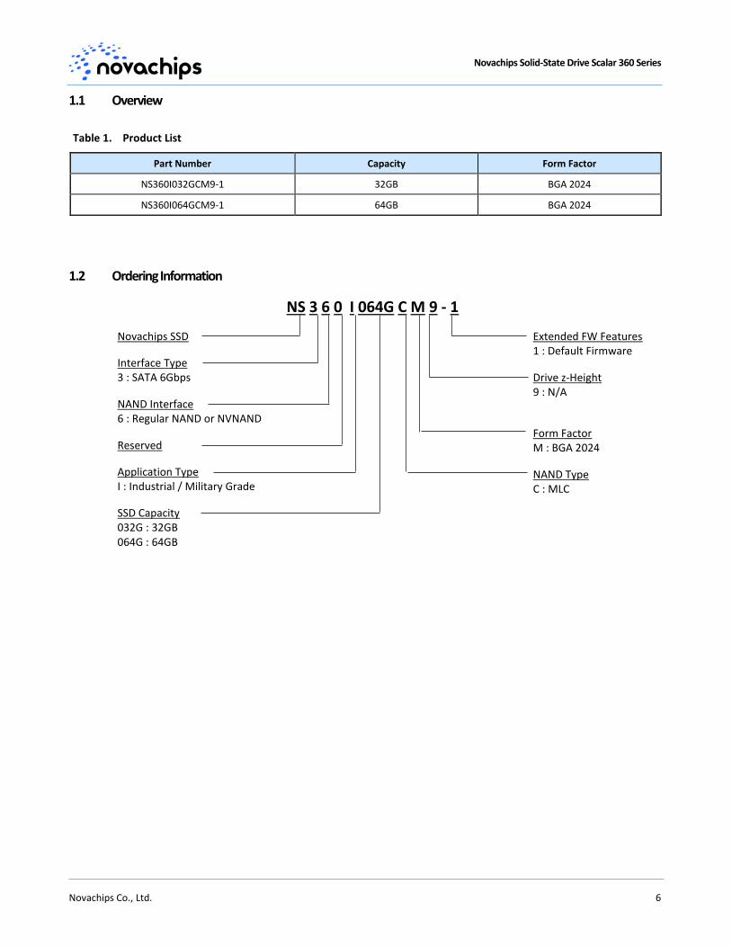
Table 1. Product List
Part Number Capacity Form Factor
NS360I032GCM9-1 32GB BGA 2024
NS360I064GCM9-1 64GB BGA 2024
1.2 Ordering Information
NS 3 6 0 I 064G C M 9 - 1
Novachips SSD
Interface Type 3 : SATA 6Gbps
NAND Interface 6 : Regular NAND or NVNAND
Reserved
Application Type I : Industrial / Military Grade
SSD Capacity 032G : 32GB 064G : 64GB
Extended FW Features 1 : Default Firmware
Drive z-Height 9 : N/A
Form Factor M : BGA 2024
NAND Type C : MLC
Novachips Solid-State Drive Scalar 360 Series
Novachips Co., Ltd. 7
2. Overview
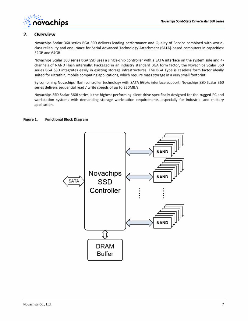
Novachips Scalar 360 series BGA SSD delivers leading performance and Quality of Service combined with world-class reliability and endurance for Serial Advanced Technology Attachment (SATA)-based computers in capacities: 32GB and 64GB.
Novachips Scalar 360 series BGA SSD uses a single-chip controller with a SATA interface on the system side and 4-channels of NAND Flash internally. Packaged in an industry standard BGA form factor, the Novachips Scalar 360 series BGA SSD integrates easily in existing storage infrastructures. The BGA Type is caseless form factor ideally suited for ultrathin, mobile computing applications, which require mass storage in a very small footprint.
By combining Novachips’ flash controller technology with SATA 6Gb/s interface support, Novachips SSD Scalar 360 series delivers sequential read / write speeds of up to 350MB/s.
Novachips SSD Scalar 360I series is the highest performing client drive specifically designed for the rugged PC and workstation systems with demanding storage workstation requirements, especially for industrial and military application.
Figure 1. Functional Block Diagram
Novachips Solid-State Drive Scalar 360 Series
Novachips Co., Ltd. 8
3. Mechanical Information
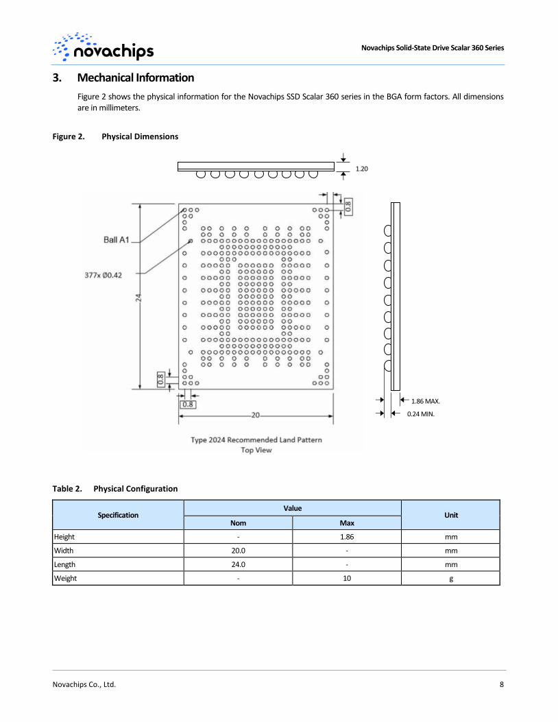
Figure 2 shows the physical information for the Novachips SSD Scalar 360 series in the BGA form factors. All dimensions are in millimeters.
Figure 2. Physical Dimensions
Table 2. Physical Configuration
Specification Value
Unit Nom Max
Height - 1.86 mm
Width 20.0 - mm
Length 24.0 - mm
Weight - 10 g
1.86 MAX.
0.24 MIN.
1.20
Novachips Solid-State Drive Scalar 360 Series
Novachips Co., Ltd. 9
4. Connector Pin Signal Definitions
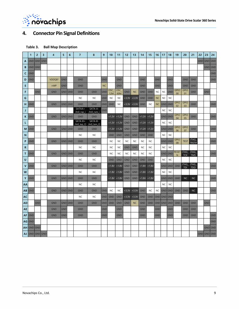
Table 3. Ball Map Description
1 2 3 4 5 6 7 8 9 10 11 12 13 14 15 16 17 18 19 20 21 22 23 24
A GND GND GND GND GND GND
B GND GND GND GND
C GND GND
D GND VDDQEF GND GND GND GND GND GND GND GND GND GND
E nWP GND GND NC GND GND GND GND GND GND
F GND GND GND GND GND GND GNDOSC_
12M
OSC_
60MGND NC GND GND NC NC GND
GPIO
00
GPIO
01GND GND
G NC NC GND NC NC +3.3V +3.3V GND GND NC NC NC
H GND GND GND GND GND GND GND GND NC +3.3V +3.3V GND NC NC GND GNDGPIO
02
GPIO
03GND GND
JSATAA+
/ln0_rxp_i
SATA-A-
/ln0_rxm_iGND NC NC
K GND GND GND GND GND GND +1.2V +1.2V GND GND +1.2V +1.2V GND GNDGPIO
04
GPIO
05GND GND
LSATA-B+
/ln0_txp_O
SATA-B-
/ln0_txm_O+1.2V +1.2V GND GND +1.2V +1.2V NC NC
M GND GND GND GND GND GND +1.2V +1.2V GND GND +1.2V +1.2V GND GNDGPIO
06
GPIO
07GND GND
N NC NC GND GND GND GND GND GND NC NC
P GND GND GND GND GND GND NC NC NC NC NC NC GND GNDGPIO
08TEST
JTAG_
TRST#GND
R NC NC NC NC GND GND NC NC NC NC
T GND GND GND GND GND GND NC NC NC NC NC NC GND GNDRESET
N
JTAG_
TCK
JTAG_
TMSGND
U NC NC GND GND GND GND GND GND NC NC
V GND GND GND GND GND GND +1.8V +1.8V GND GND +1.8V +1.8V GND GND GNDJTAG_
TDI
JTAG_
TDOGND
W NC NC +1.8V +1.8V GND GND +1.8V +1.8V NC NC
Y GND GND GND GND GND GND +1.8V +1.8V GND GND +1.8V +1.8V GND GND GND NC NC GND
AA NC NC NC NC
AB GND GND GND GND GND GND GND NC NC +3.3V +3.3V GND NC NC GND GND GND GND NC GND
AC NC NC GND GND GND +3.3V +3.3V GND GND GND GND GND
AD GND GND GND GND GND GND GND GND GND GND NC GND GND GND GND GND GND GND GND GND
AE GND GND GND GND GND GND GND GND GND GND
AF GND GND GND GND GND GND GND GND GND GND GND GND
AG GND GND
AH GND GND GND GND
AJ GND GND GND GND GND GND
Novachips Solid-State Drive Scalar 360 Series
Novachips Co., Ltd. 10
5. Electrical Characteristics
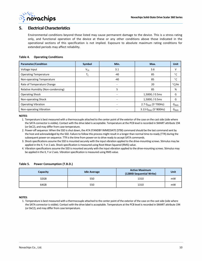
Environmental conditions beyond those listed may cause permanent damage to the device. This is a stress rating only, and functional operation of the device at these or any other conditions above those indicated in the operational sections of this specification is not implied. Exposure to absolute maximum rating conditions for extended periods may affect reliability.
Table 4. Operating Conditions
Parameter/Condition Symbol Min. Max. Unit
Voltage Input V33 3.1 3.6 V
Operating Temperature TC -40 85 C
Non-operating Temperature -40 85 C
Rate of Temperature Change - 20 C/Hr
Relative Humidity (Non-condensing) 5 85 %
Operating Shock - 1,500G / 0.5ms G
Non-operating Shock - 1,500G / 0.5ms G
Operating Vibration - 2.7 GRMS (5~700Hz) GRMS
Non-operating Vibration - 3.13 GRMS (5~800Hz) GRMS
NOTES: 1. Temperature is best measured with a thermocouple attached to the center point of the exterior of the case on the cast side (side where
the SATA connector is visible). Contact with the drive label is acceptable. Temperature at the PCB level is recorded in SMART attribute 194 (or 0xC2), and may differ from case temperature.
2. Power-off sequence: When the SSD is shut down, the ATA STANDBY IMMEDIATE (STBI) command should be the last command sent by the host and acknowledged by the SSD. Failure to follow this process might result in a longer than normal time-to-ready (TTR) during the subsequent power-on sequence. TTR is the time from power-on to drive ready to accept SATA commands.
3. Shock specifications assume the SSD is mounted securely with the input vibration applied to the drive-mounting screws. Stimulus may be applied in the X, Y or Z axis. Shock specification is measured using Root Mean Squared (RMS) value.
4. Vibration specifications assume the SSD is mounted securely with the input vibration applied to the drive-mounting screws. Stimulus may be applied in the X, Y or Z axis. Vibration specification is measured using RMS value.
Table 5. Power Consumption (T.B.D.)
Capacity Idle Average Active Maximum
(128KB Sequential Write) Unit
32GB 550 1310 mW
64GB 550 1310 mW
NOTES: 1. Temperature is best measured with a thermocouple attached to the center point of the exterior of the case on the cast side (side where
the SATA connector is visible). Contact with the drive label is acceptable. Temperature at the PCB level is recorded in SMART attribute 194 (or 0xC2), and may differ from case temperature.
Novachips Solid-State Drive Scalar 360 Series
Novachips Co., Ltd. 11
6. Product Specifications
6.1 Capacity
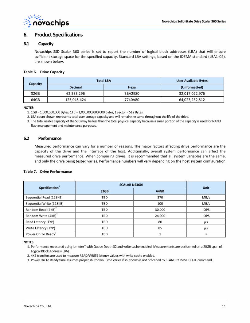
Novachips SSD Scalar 360 series is set to report the number of logical block addresses (LBA) that will ensure sufficient storage space for the specified capacity. Standard LBA settings, based on the IDEMA standard (LBA1-02), are shown below.
Table 6. Drive Capacity
Capacity Total LBA User Available Bytes
Decimal Hexa (Unformatted)
32GB 62,533,296 3BA2E80 32,017,022,976
64GB 125,045,424 7740A80 64,023,232,512
NOTES: 1. 1GB = 1,000,000,000 Bytes, 1TB = 1,000,000,000,000 Bytes; 1 sector = 512 Bytes. 2. LBA count shown represents total user storage capacity and will remain the same throughout the life of the drive. 3. The total usable capacity of the SSD may be less than the total physical capacity because a small portion of the capacity is used for NAND
flash management and maintenance purposes.
6.2 Performance
Measured performance can vary for a number of reasons. The major factors affecting drive performance are the capacity of the drive and the interface of the host. Additionally, overall system performance can affect the measured drive performance. When comparing drives, it is recommended that all system variables are the same, and only the drive being tested varies. Performance numbers will vary depending on the host system configuration.
Table 7. Drive Performance
Specification1
SCALAR NS360I Unit
32GB 64GB
Sequential Read (128KB) TBD 370 MB/s
Sequential Write (128KB) TBD 100 MB/s
Random Read (4KB)2 TBD 30,000 IOPS
Random Write (4KB)2 TBD 24,000 IOPS
Read Latency (TYP) TBD 80 s
Write Latency (TYP) TBD 85 s
Power On To Ready3 TBD 1 s
NOTES: 1. Performance measured using Iometer* with Queue Depth 32 and write cache enabled. Measurements are performed on a 20GB span of
Logical Block Address (LBA). 2. 4KB transfers are used to measure READ/WRITE latency values with write cache enabled. 3. Power On To Ready time assumes proper shutdown. Time varies if shutdown is not preceded by STANDBY IMMEDIATE command.
Novachips Solid-State Drive Scalar 360 Series
Novachips Co., Ltd. 12
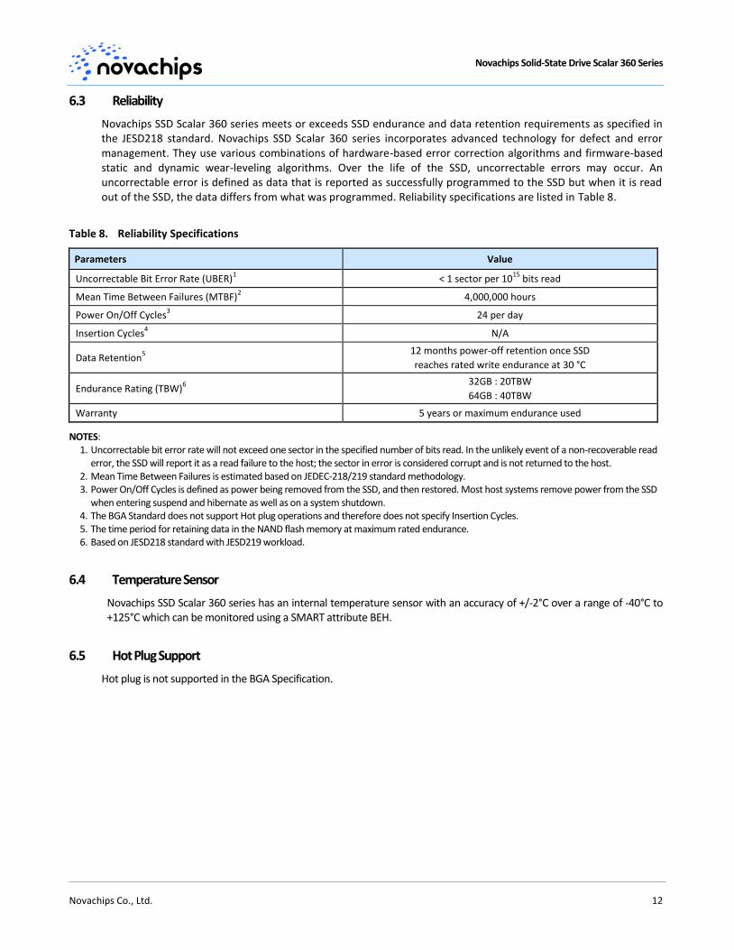
6.3 Reliability
Novachips SSD Scalar 360 series meets or exceeds SSD endurance and data retention requirements as specified in the JESD218 standard. Novachips SSD Scalar 360 series incorporates advanced technology for defect and error management. They use various combinations of hardware-based error correction algorithms and firmware-based static and dynamic wear-leveling algorithms. Over the life of the SSD, uncorrectable errors may occur. An uncorrectable error is defined as data that is reported as successfully programmed to the SSD but when it is read out of the SSD, the data differs from what was programmed. Reliability specifications are listed in Table 8.
Table 8. Reliability Specifications
Parameters Value
Uncorrectable Bit Error Rate (UBER)1 < 1 sector per 10
15 bits read
Mean Time Between Failures (MTBF)2 4,000,000 hours
Power On/Off Cycles3 24 per day
Insertion Cycles4 N/A
Data Retention5
12 months power-off retention once SSD
reaches rated write endurance at 30 °C
Endurance Rating (TBW)6
32GB : 20TBW
64GB : 40TBW
Warranty 5 years or maximum endurance used
NOTES: 1. Uncorrectable bit error rate will not exceed one sector in the specified number of bits read. In the unlikely event of a non-recoverable read
error, the SSD will report it as a read failure to the host; the sector in error is considered corrupt and is not returned to the host. 2. Mean Time Between Failures is estimated based on JEDEC-218/219 standard methodology. 3. Power On/Off Cycles is defined as power being removed from the SSD, and then restored. Most host systems remove power from the SSD
when entering suspend and hibernate as well as on a system shutdown. 4. The BGA Standard does not support Hot plug operations and therefore does not specify Insertion Cycles. 5. The time period for retaining data in the NAND flash memory at maximum rated endurance. 6. Based on JESD218 standard with JESD219 workload.
6.4 Temperature Sensor
Novachips SSD Scalar 360 series has an internal temperature sensor with an accuracy of +/-2°C over a range of -40°C to +125°C which can be monitored using a SMART attribute BEH.
6.5 Hot Plug Support
Hot plug is not supported in the BGA Specification.
Novachips Solid-State Drive Scalar 360 Series
Novachips Co., Ltd. 13
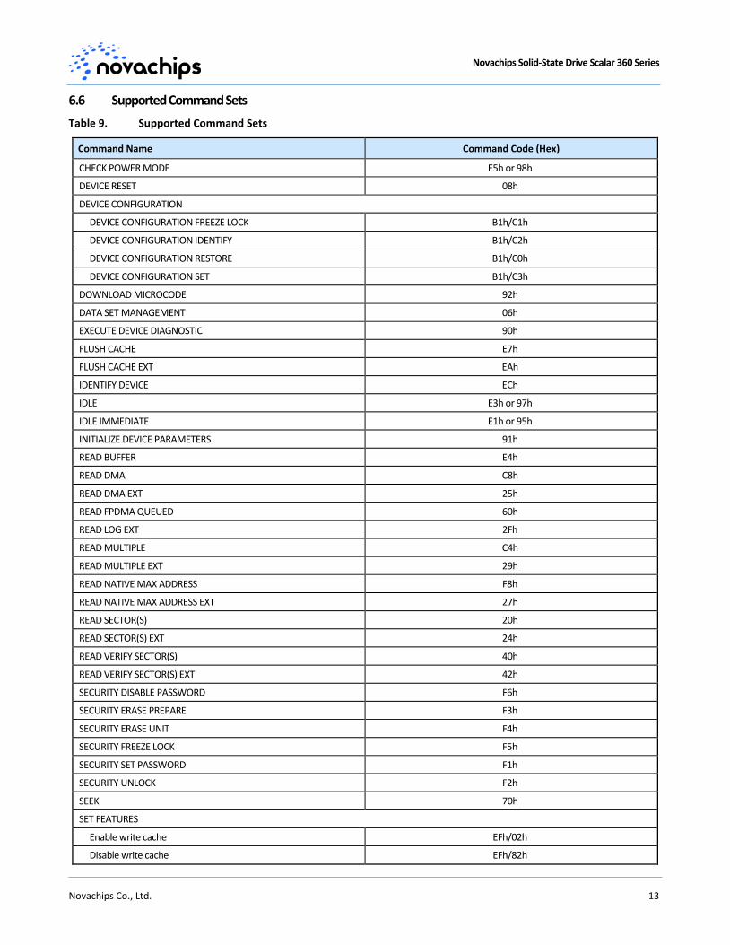
6.6 Supported Command Sets
Table 9. Supported Command Sets
Command Name Command Code (Hex)
CHECK POWER MODE E5h or 98h
DEVICE RESET 08h
DEVICE CONFIGURATION
DEVICE CONFIGURATION FREEZE LOCK B1h/C1h
DEVICE CONFIGURATION IDENTIFY B1h/C2h
DEVICE CONFIGURATION RESTORE B1h/C0h
DEVICE CONFIGURATION SET B1h/C3h
DOWNLOAD MICROCODE 92h
DATA SET MANAGEMENT 06h
EXECUTE DEVICE DIAGNOSTIC 90h
FLUSH CACHE E7h
FLUSH CACHE EXT EAh
IDENTIFY DEVICE ECh
IDLE E3h or 97h
IDLE IMMEDIATE E1h or 95h
INITIALIZE DEVICE PARAMETERS 91h
READ BUFFER E4h
READ DMA C8h
READ DMA EXT 25h
READ FPDMA QUEUED 60h
READ LOG EXT 2Fh
READ MULTIPLE C4h
READ MULTIPLE EXT 29h
READ NATIVE MAX ADDRESS F8h
READ NATIVE MAX ADDRESS EXT 27h
READ SECTOR(S) 20h
READ SECTOR(S) EXT 24h
READ VERIFY SECTOR(S) 40h
READ VERIFY SECTOR(S) EXT 42h
SECURITY DISABLE PASSWORD F6h
SECURITY ERASE PREPARE F3h
SECURITY ERASE UNIT F4h
SECURITY FREEZE LOCK F5h
SECURITY SET PASSWORD F1h
SECURITY UNLOCK F2h
SEEK 70h
SET FEATURES
Enable write cache EFh/02h
Disable write cache EFh/82h
Novachips Solid-State Drive Scalar 360 Series
Novachips Co., Ltd. 14
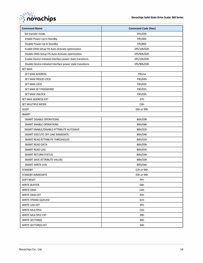
Command Name Command Code (Hex)
Set transfer mode EFh/03h
Enable Power-Up In Standby Efh/06h
Disable Power-Up In Standby Efh/86h
Enable DMA Setup FIS Auto-Activate optimization Efh/10h/02h
Disable DMA Setup FIS Auto-Activate optimization Efh/90h/02h
Enable Device-initiated interface power state transitions Efh/10h/03h
Disable Device-initiated interface power state transitions Efh/90h/03h
SET MAX
SET MAX ADDRESS F9h/na
SET MAX FREEZE LOCK F9h/04h
SET MAX LOCK F9h/02h
SET MAX SET PASSWORD F9h/01h
SET MAX UNLOCK F9h/03h
SET MAX ADDRESS EXT 37h
SET MULTIPLE MODE C6h
SLEEP E6h or 99h
SMART
SMART DISABLE OPERATIONS B0h/D9h
SMART ENABLE OPERATIONS B0h/D8h
SMART ENABLE/DISABLE ATTRIBUTE AUTOSAVE B0h/D2h
SMART EXECUTE OFF-LINE IMMIDIATE B0h/D4h
SMART READ ATTRIBUTE THRESHOLDS B0h/D1h
SMART READ DATA B0h/D0h
SMART READ LOG B0h/D5h
SMART RETURN STATUS B0h/DAh
SMART SAVE ATTRIBUTE VALUES B0h/D3h
SMART WRITE LOG B0h/D6h
STANDBY E2h or 96h
STANDBY IMMEDIATE E0h or 94h
SOFT RESET FFh
WRITE BUFFER E8h
WRITE DMA CAh
WRITE DMA EXT 35h
WRITE FPDMA QUEUED 61h
WRITE LOG EXT 3Fh
WRITE MULTIPLE C5h
WRITE MULTIPLE EXT 39h
WRITE SECTOR(S) 30h
WRITE SECTOR(S) EXT 34h
Novachips Solid-State Drive Scalar 360 Series
Novachips Co., Ltd. 15
6.7 SMART
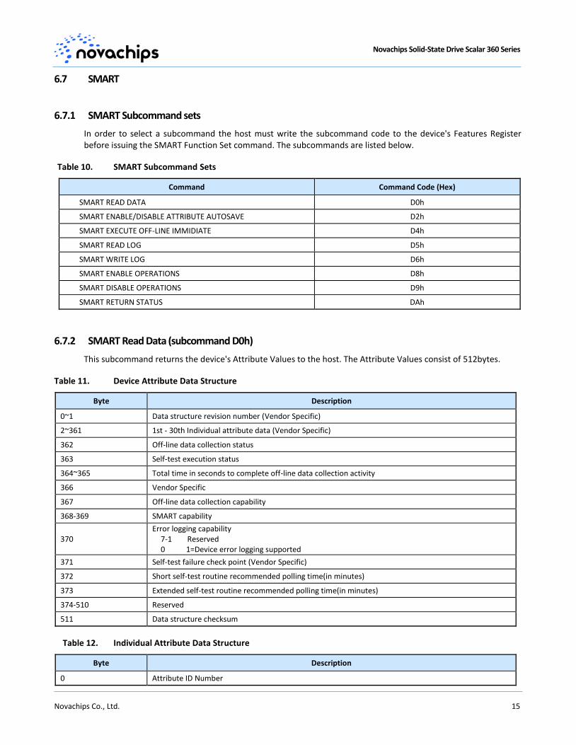
6.7.1 SMART Subcommand sets
In order to select a subcommand the host must write the subcommand code to the device's Features Register before issuing the SMART Function Set command. The subcommands are listed below.
Table 10. SMART Subcommand Sets
Command Command Code (Hex)
SMART READ DATA D0h
SMART ENABLE/DISABLE ATTRIBUTE AUTOSAVE D2h
SMART EXECUTE OFF-LINE IMMIDIATE D4h
SMART READ LOG D5h
SMART WRITE LOG D6h
SMART ENABLE OPERATIONS D8h
SMART DISABLE OPERATIONS D9h
SMART RETURN STATUS DAh
6.7.2 SMART Read Data (subcommand D0h)
This subcommand returns the device's Attribute Values to the host. The Attribute Values consist of 512bytes.
Table 11. Device Attribute Data Structure
Byte Description
0~1 Data structure revision number (Vendor Specific)
2~361 1st - 30th Individual attribute data (Vendor Specific)
362 Off-line data collection status
363 Self-test execution status
364~365 Total time in seconds to complete off-line data collection activity
366 Vendor Specific
367 Off-line data collection capability
368-369 SMART capability
370 Error logging capability
7-1 Reserved 0 1=Device error logging supported
371 Self-test failure check point (Vendor Specific)
372 Short self-test routine recommended polling time(in minutes)
373 Extended self-test routine recommended polling time(in minutes)
374-510 Reserved
511 Data structure checksum
Table 12. Individual Attribute Data Structure
Byte Description
0 Attribute ID Number

Novachips Solid-State Drive Scalar 360 Series
Novachips Co., Ltd. 16
1~2 Flags
3 Current Value
4 Worst Value
5~10 Attribute Value (FFFF FFFF FFFFh)
11 Reserved
Table 13. Attribute ID Numbers
ID(DEC) ID(HEX) Attribute Name Description (1015~)
1 01h Raw Read Error Rate * Counts of read-retry operation to read data from flash
9 09h Power-On Hours The time amount of power-on state (unit: minute)
12 0Ch Power Cycle Count Counts of full power on/off cycles
13 0Dh Soft Read Error Rate Corrected ECC error event counts which exceed warning ECC error threshold level
175 AFh Program Failure Block Count Counts the number of flash program failures
176 B0h Erase Failure Block Count Counts the number of flash erase failures
184 B8h Initial Bad Block Count The number of bad blocks which was detected when firmware was installed
185 B9h Running Bad Block Count The number of increased bad blocks after firmware was installed (erase and program failure)
192 C0h Unexpected Power Shutdown Count The number of unexpected power outages when the device shutdown without “STNADBY IMMEDIATE” command
194 C2h Temperature Current device temperature (unit: ℃)
199 C7h Read Failure Block Count (Uncorrectable)
Uncorrectable read failure block count
200 C8h Total count of write commands The total number of written command during the entire lifetime of the device
201 C9h Total count of read commands The total number of read command during the entire lifetime of the device
202 CAh Total count of write sectors Requested by Host
The total amount of sector counts written from the host
203 CBh Total Sectors Written to Flash The total amount of sector counts written (program) to flash
204 CCh Total Read Sectors Requested by Host
The total amount of sector counts read from the host
209 D1h SSD Life Left(Remaining Drive Life) Indicates the approximate SSD life left [(maximum PE cycle – average erase count) / maximum PE cycle]
210 D2h Minimum Erase Count The erase count of flash bank which erased least
211 D3h Maximum Erase Count The erase counts of flash bank which erased most
212 D4h Average Erase Count The average erase counts of all flash banks
213 D5h Maximum PE Cycle Count Returns maximum PE cycle counts of flash
221 DDh Bad Block Full Flag Returns ‘1’ when total bad block percentage reaches over 5% of all banks. (normally returns ‘0’)
223 DFh SATA Error CRC Count The number of encountered SATA interface cyclic redundancy check (CRC) errors
224 E0h SATA Error Handshake Count The number of encountered SATA interface Handshake errors
225 E1h SATA Offline SATA offline count
00~15 : SATA re-connecntion count after power-on
16~47 : vendor-specific
226 E2h Vendor-specific Vendor-specific
227 E3h Device Status Device status
00 : device protected
01 : firmware update protected
02~07 : vendor specific
Novachips Solid-State Drive Scalar 360 Series
Novachips Co., Ltd. 17
08: Write protected status
09~15 : vendor specific
16~17 : test mode status
18~47 : vendor specific
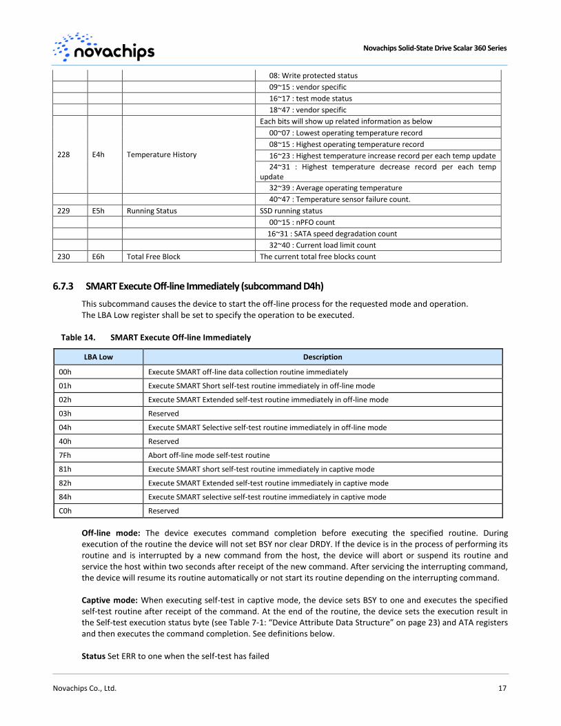
228 E4h Temperature History
Each bits will show up related information as below
00~07 : Lowest operating temperature record
08~15 : Highest operating temperature record
16~23 : Highest temperature increase record per each temp update
24~31 : Highest temperature decrease record per each temp update
32~39 : Average operating temperature
40~47 : Temperature sensor failure count.
229 E5h Running Status SSD running status
00~15 : nPFO count
16~31 : SATA speed degradation count
32~40 : Current load limit count
230 E6h Total Free Block The current total free blocks count
6.7.3 SMART Execute Off-line Immediately (subcommand D4h)
This subcommand causes the device to start the off-line process for the requested mode and operation. The LBA Low register shall be set to specify the operation to be executed.
Table 14. SMART Execute Off-line Immediately
LBA Low Description
00h Execute SMART off-line data collection routine immediately
01h Execute SMART Short self-test routine immediately in off-line mode
02h Execute SMART Extended self-test routine immediately in off-line mode
03h Reserved
04h Execute SMART Selective self-test routine immediately in off-line mode
40h Reserved
7Fh Abort off-line mode self-test routine
81h Execute SMART short self-test routine immediately in captive mode
82h Execute SMART Extended self-test routine immediately in captive mode
84h Execute SMART selective self-test routine immediately in captive mode
C0h Reserved
Off-line mode: The device executes command completion before executing the specified routine. During execution of the routine the device will not set BSY nor clear DRDY. If the device is in the process of performing its routine and is interrupted by a new command from the host, the device will abort or suspend its routine and service the host within two seconds after receipt of the new command. After servicing the interrupting command, the device will resume its routine automatically or not start its routine depending on the interrupting command. Captive mode: When executing self-test in captive mode, the device sets BSY to one and executes the specified self-test routine after receipt of the command. At the end of the routine, the device sets the execution result in the Self-test execution status byte (see Table 7-1: “Device Attribute Data Structure” on page 23) and ATA registers and then executes the command completion. See definitions below. Status Set ERR to one when the self-test has failed
Novachips Solid-State Drive Scalar 360 Series
Novachips Co., Ltd. 18
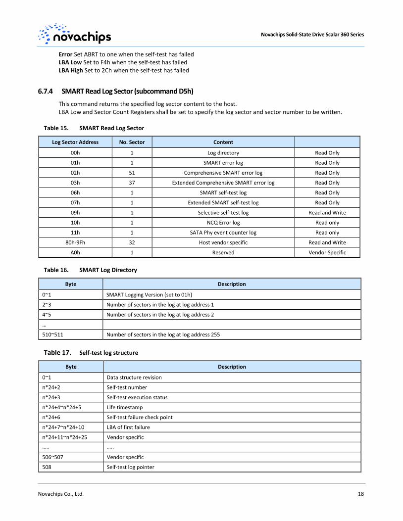
Error Set ABRT to one when the self-test has failed LBA Low Set to F4h when the self-test has failed LBA High Set to 2Ch when the self-test has failed
6.7.4 SMART Read Log Sector (subcommand D5h)
This command returns the specified log sector content to the host. LBA Low and Sector Count Registers shall be set to specify the log sector and sector number to be written.
Table 15. SMART Read Log Sector
Log Sector Address No. Sector Content
00h 1 Log directory Read Only
01h 1 SMART error log Read Only
02h 51 Comprehensive SMART error log Read Only
03h 37 Extended Comprehensive SMART error log Read Only
06h 1 SMART self-test log Read Only
07h 1 Extended SMART self-test log Read Only
09h 1 Selective self-test log Read and Write
10h 1 NCQ Error log Read only
11h 1 SATA Phy event counter log Read only
80h-9Fh 32 Host vendor specific Read and Write
A0h 1 Reserved Vendor Specific
Table 16. SMART Log Directory
Byte Description
0~1 SMART Logging Version (set to 01h)
2~3 Number of sectors in the log at log address 1
4~5 Number of sectors in the log at log address 2
…
510~511 Number of sectors in the log at log address 255
Table 17. Self-test log structure
Byte Description
0~1 Data structure revision
n*24+2 Self-test number
n*24+3 Self-test execution status
n*24+4~n*24+5 Life timestamp
n*24+6 Self-test failure check point
n*24+7~n*24+10 LBA of first failure
n*24+11~n*24+25 Vendor specific
….. …..
506~507 Vendor specific
508 Self-test log pointer
Novachips Solid-State Drive Scalar 360 Series
Novachips Co., Ltd. 19
Byte Description
509~510 Reserved
511 Data structure checksum
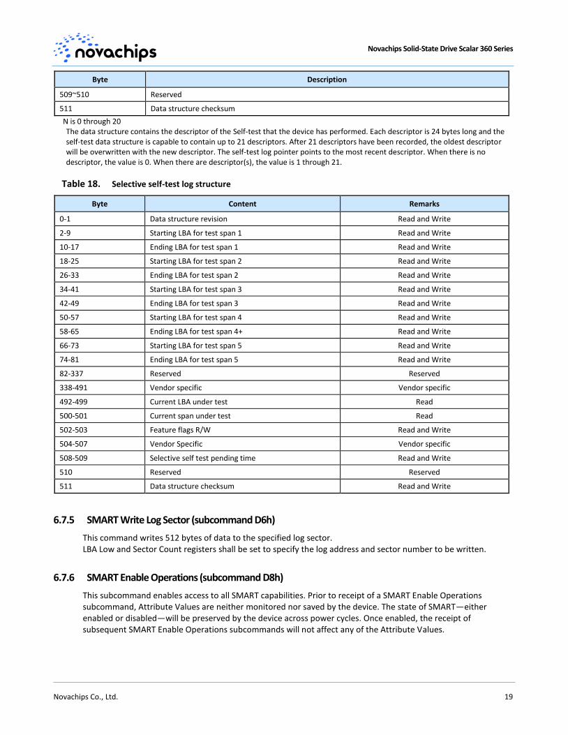
N is 0 through 20 The data structure contains the descriptor of the Self-test that the device has performed. Each descriptor is 24 bytes long and the self-test data structure is capable to contain up to 21 descriptors. After 21 descriptors have been recorded, the oldest descriptor will be overwritten with the new descriptor. The self-test log pointer points to the most recent descriptor. When there is no descriptor, the value is 0. When there are descriptor(s), the value is 1 through 21.
Table 18. Selective self-test log structure
Byte Content Remarks
0-1 Data structure revision Read and Write
2-9 Starting LBA for test span 1 Read and Write
10-17 Ending LBA for test span 1 Read and Write
18-25 Starting LBA for test span 2 Read and Write
26-33 Ending LBA for test span 2 Read and Write
34-41 Starting LBA for test span 3 Read and Write
42-49 Ending LBA for test span 3 Read and Write
50-57 Starting LBA for test span 4 Read and Write
58-65 Ending LBA for test span 4+ Read and Write
66-73 Starting LBA for test span 5 Read and Write
74-81 Ending LBA for test span 5 Read and Write
82-337 Reserved Reserved
338-491 Vendor specific Vendor specific
492-499 Current LBA under test Read
500-501 Current span under test Read
502-503 Feature flags R/W Read and Write
504-507 Vendor Specific Vendor specific
508-509 Selective self test pending time Read and Write
510 Reserved Reserved
511 Data structure checksum Read and Write
6.7.5 SMART Write Log Sector (subcommand D6h)
This command writes 512 bytes of data to the specified log sector. LBA Low and Sector Count registers shall be set to specify the log address and sector number to be written.
6.7.6 SMART Enable Operations (subcommand D8h)
This subcommand enables access to all SMART capabilities. Prior to receipt of a SMART Enable Operations subcommand, Attribute Values are neither monitored nor saved by the device. The state of SMART—either enabled or disabled—will be preserved by the device across power cycles. Once enabled, the receipt of subsequent SMART Enable Operations subcommands will not affect any of the Attribute Values.

Novachips Solid-State Drive Scalar 360 Series
Novachips Co., Ltd. 20
6.7.7 SMART Disable Operations (subcommand D9h)
This subcommand disables all SMART capabilities. After receipt of this subcommand the device disables all SMART operations. Non self-preserved Attribute Values will no longer be monitored. The state of SMART—either enabled or disabled—is preserved by the device across power cycles. Note that this subcommand does not preclude the device's power mode attribute auto saving. After receipt of the SMART Disable Operations subcommand from the host, all other SMART subcommands except SMART Enable Operations are disabled and will be aborted by the device returning the error code as specified in “SMART Error Codes”. Any Attribute Values accumulated and saved to volatile memory prior to receipt of the SMART Disable Operations command will be preserved in the device's Attribute Data Sectors. If the device is re-enabled, these Attribute Values will be updated, as needed, upon receipt of a SMART Read Attribute Values or a SMART Save Attribute Values command.
6.7.8 SMART Return Status (subcommand DAh)
This subcommand is used to communicate the reliability status of the device to the host's request. Upon receipt of the SMART Return Status subcommand the device saves any updated Attribute Values to the reserved sector, and compares the updated Attribute Values to the Attribute Thresholds.
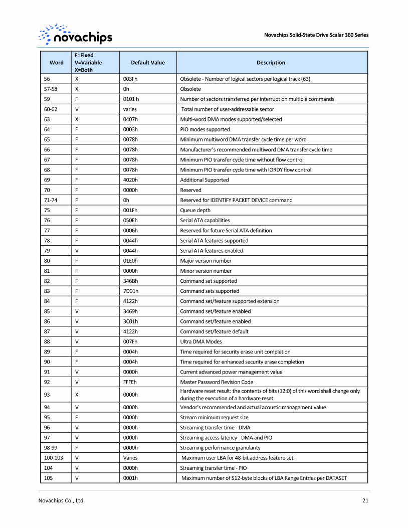
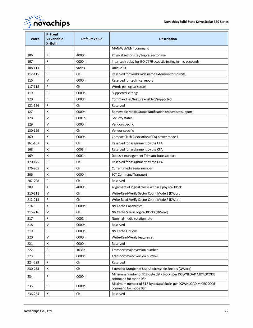
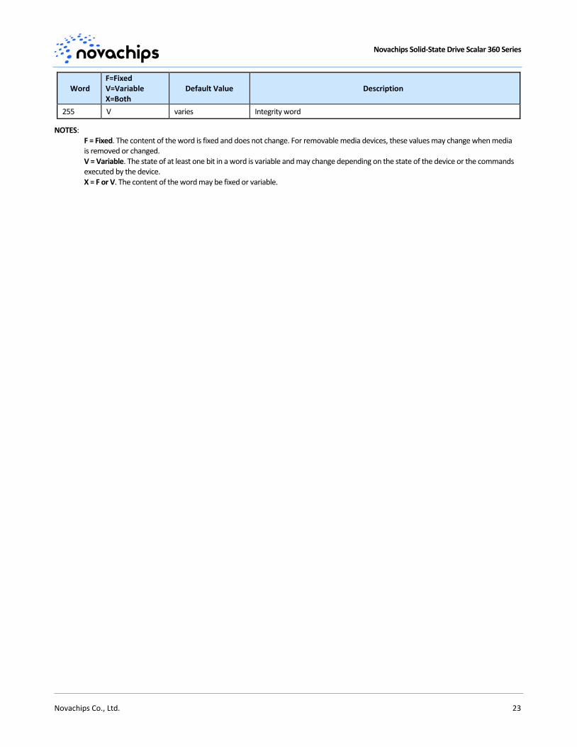
6.8 IDENTIFY DEVICE Command Data
Table 19. Returned Sector Data
Word F=Fixed V=Variable X=Both
Default Value Description
0 X 0040h General configuration bit-significant information
1 X 3FFFh Obsolete - Number of logical cylinders (16,383)
2 V C837h Specific configuration
3 X 0010h Obsolete - Number of logical heads (16)
4-5 X 0h Retired
6 X 003Fh Obsolete - Number of logical sectors per logical track (63)
7-8 V 0h Reserved for assignment by the CompactFlash* Association (CFA)
9 X 0h Retired
10-19 F varies Serial number (20 ASCII characters)
20-21 X 0h Retired
22 X 0000h Obsolete
23-26 F varies Firmware revision (8 ASCII characters)
27-46 F varies Model number
47 F 8001h Maximum number of sectors transferred per interrupt on multiple commands
48 F 4000h Trusted Computing Feature Set
49 F 2F00h Capabilities
50 F 4000h Capabilities
51-52 X 0h Obsolete
53 F 0007h Words 88 and 70:64 valid
54 X 3FFFh Obsolete - Number of logical cylinders (16,383)
55 X 0010h Obsolete - Number of logical heads (16)
Novachips Solid-State Drive Scalar 360 Series
Novachips Co., Ltd. 21
Word F=Fixed V=Variable X=Both
Default Value Description
56 X 003Fh Obsolete - Number of logical sectors per logical track (63)
57-58 X 0h Obsolete
59 F 0101 h Number of sectors transferred per interrupt on multiple commands
60-62 V varies Total number of user-addressable sector
63 X 0407h Multi-word DMA modes supported/selected
64 F 0003h PIO modes supported
65 F 0078h Minimum multiword DMA transfer cycle time per word
66 F 0078h Manufacturer’s recommended multiword DMA transfer cycle time
67 F 0078h Minimum PIO transfer cycle time without flow control
68 F 0078h Minimum PIO transfer cycle time with IORDY flow control
69 F 4020h Additional Supported
70 F 0000h Reserved
71-74 F 0h Reserved for IDENTIFY PACKET DEVICE command
75 F 001Fh Queue depth
76 F 050Eh Serial ATA capabilities
77 F 0006h Reserved for future Serial ATA definition
78 F 0044h Serial ATA features supported
79 V 0044h Serial ATA features enabled
80 F 01E0h Major version number
81 F 0000h Minor version number
82 F 346Bh Command set supported
83 F 7D01h Command sets supported
84 F 4122h Command set/feature supported extension
85 V 3469h Command set/feature enabled
86 V 3C01h Command set/feature enabled
87 V 4122h Command set/feature default
88 V 007Fh Ultra DMA Modes
89 F 0004h Time required for security erase unit completion
90 F 0004h Time required for enhanced security erase completion
91 V 0000h Current advanced power management value
92 V FFFEh Master Password Revision Code
93 X 0000h Hardware reset result: the contents of bits (12:0) of this word shall change only during the execution of a hardware reset
94 V 0000h Vendor’s recommended and actual acoustic management value
95 F 0000h Stream minimum request size
96 V 0000h Streaming transfer time - DMA
97 V 0000h Streaming access latency - DMA and PIO
98-99 F 0000h Streaming performance granularity
100-103 V Varies Maximum user LBA for 48-bit address feature set
104 V 0000h Streaming transfer time - PIO
105 V 0001h Maximum number of 512-byte blocks of LBA Range Entries per DATASET
Novachips Solid-State Drive Scalar 360 Series
Novachips Co., Ltd. 22
Word F=Fixed V=Variable X=Both
Default Value Description
MANAGEMENT command
106 F 4000h Physical sector size / logical sector size
107 F 0000h Inter-seek delay for ISO-7779 acoustic testing in microseconds
108-111 F varies Unique ID
112-115 F 0h Reserved for world wide name extension to 128 bits
116 V 0000h Reserved for technical report
117-118 F 0h Words per logical sector
119 F 0000h Supported settings
120 F 0000h Command set/feature enabled/supported
121-126 F 0h Reserved
127 X 0000h Removable Media Status Notification feature set support
128 V 0001h Security status
129 V 0000h Vendor-specific
130-159 X 0h Vendor-specific
160 X 0000h CompactFlash Association (CFA) power mode 1
161-167 X 0h Reserved for assignment by the CFA
168 X 0003h Reserved for assignment by the CFA
169 X 0001h Data set management Trim attribute support
170-175 F 0h Reserved for assignment by the CFA
176-205 X 0h Current media serial number
206 X 0000h SCT Command Transport
207-208 F 0h Reserved
209 X 4000h Alignment of logical blocks within a physical block
210-211 V 0h Write-Read-Verify Sector Count Mode 3 (DWord)
212-213 F 0h Write-Read-Verify Sector Count Mode 2 (DWord)
214 X 0000h NV Cache Capabilities
215-216 V 0h NV Cache Size in Logical Blocks (DWord)
217 F 0001h Nominal media rotation rate
218 V 0000h Reserved
219 F 0000h NV Cache Options
220 V 0000h Write-Read-Verify feature set
221 X 0000h Reserved
222 F 103Fh Transport major version number
223 F 0000h Transport minor version number
224-229 F 0h Reserved
230-233 X 0h Extended Number of User Addressable Sectors (QWord)
234 F 0000h Minimum number of 512-byte data blocks per DOWNLOAD MICROCODE command for mode 03h
235 F 0000h Maximum number of 512-byte data blocks per DOWNLOAD MICROCODE command for mode 03h
236-254 X 0h Reserved
Novachips Solid-State Drive Scalar 360 Series
Novachips Co., Ltd. 23
Word F=Fixed V=Variable X=Both
Default Value Description
255 V varies Integrity word
NOTES: F = Fixed. The content of the word is fixed and does not change. For removable media devices, these values may change when media is removed or changed. V = Variable. The state of at least one bit in a word is variable and may change depending on the state of the device or the commands executed by the device. X = F or V. The content of the word may be fixed or variable.
Novachips Solid-State Drive Scalar 360 Series
Novachips Co., Ltd. 24
7. Product Compliance
7.1 Product Regulatory Compliance and Certifications
Table 20. Certifications and Declarations
Category Certification
CE Comunaute Europeenne
KCC Korea Communications commission
FCC Federal Communications Commission
7.2 FCC Rules
This equipment has been tested and found to comply with the limits for a Class B digital device, pursuant to part 15 of the FCC Rules. These limits are designed to provide reasonable protection against harmful interference in a residential installation. This equipment generates, uses, and can radiate radio frequency energy and, if not installed and used in accordance with the instructions, may cause harmful interference to radio communications. However, there is no guarantee that interference will not occur in a particular installation. If this equipment does cause harmful interference to radio or television reception, which can be determined by turning the equipment off and on, the user is encouraged to try to correct the interference by one or more of the following measures:
• Reorient or relocate the receiving antenna. • Increase the separation between the equipment and the receiver. • Connect the equipment into an outlet on a circuit different from that to which the receiver is connected. • Consult the dealer or an experienced radio/TV technician for help.

Novachips Solid-State Drive Scalar 360 Series
Novachips Co., Ltd. 25
8. References
Serial ATA: High-speed serialized AT attachment, Serial ATA working group, available at www.sata-io.org
SATA 3.1 GOLD, and the following:
– DEVSLP, SATA31_TPR_C108 rev. 1.0a 10/24/2011
– SATA TP #37, Standard SATA Connector 3.3V Power Pin Assignments, Rev. 1.1 10/12/2011
– SATA TP #39, DEVSLP Assignment on Standard SATA Connector, Rev. 01 01/02/12
ATA-8 ACS2 (T13/2015-D, Revision 4), and the following:
– Device Internal Logs (supports SSD Telemetry)
– IDFY Device Data Logs (supports DEVSLP)
IEEE-1667: "Standard Protocol for Authentication in Host Attachments of Transient Storage Devices".
Related Documents


![Terhadap Tegangan Flashover dan Arus Bocor pada Isolator ... file(NaCl) 10gram dan 20gram. [1] B. Tujuan Tujuan pembuatan tugas akhir ini adalah untuk menganalisis pengaruh Equvalent](https://static.cupdf.com/doc/110x72/5c8e922509d3f2d9168cdd96/terhadap-tegangan-flashover-dan-arus-bocor-pada-isolator-nacl-10gram-dan-20gram.jpg)