Ideal For Biomass NOVA ® NOVA ® Twin wall, insulated stainless steel multi-fuel chimney system Suitable for multifuel stoves, wood-fired biomass appliances, fully condensing and positive pressure applications 100% Manufactured in the UK

Welcome message from author
This document is posted to help you gain knowledge. Please leave a comment to let me know what you think about it! Share it to your friends and learn new things together.
Transcript

Ideal For BiomassNOVA®
NOVA®
Twin wall, insulated stainless steel multi-fuel chimney system
Suitable for multifuel stoves, wood-fired biomass appliances, fully condensing and positive pressure applications
100% Manufacturedin the UK
2
SFL Flues & Chimneys – Formerly known as Selkirk ManufacturingIn 2003, SFL was born from the assets of Selkirk Manufacturing. Over a decade later, SFL is enjoying ever-increasing success in UK and International markets with time-honoured, established brands that are synonymous with quality and performance.
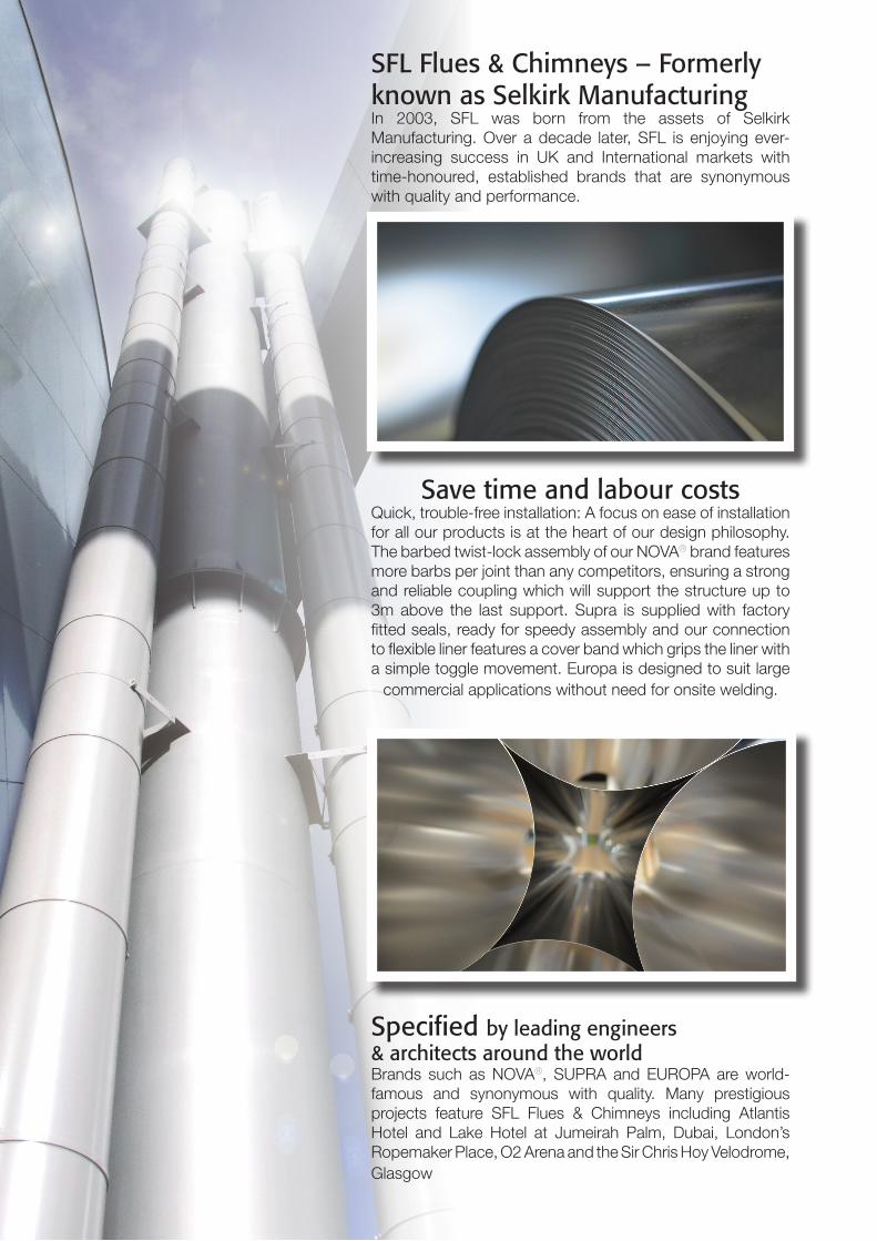
Save time and labour costsQuick, trouble-free installation: A focus on ease of installation for all our products is at the heart of our design philosophy. The barbed twist-lock assembly of our NOVA® brand features more barbs per joint than any competitors, ensuring a strong and reliable coupling which will support the structure up to 3m above the last support. Supra is supplied with factory fitted seals, ready for speedy assembly and our connection to flexible liner features a cover band which grips the liner with a simple toggle movement. Europa is designed to suit large
commercial applications without need for onsite welding.
Specified by leading engineers& architects around the worldBrands such as NOVA®, SUPRA and EUROPA are world-famous and synonymous with quality. Many prestigious projects feature SFL Flues & Chimneys including Atlantis Hotel and Lake Hotel at Jumeirah Palm, Dubai, London’s Ropemaker Place, O2 Arena and the Sir Chris Hoy Velodrome, Glasgow
3
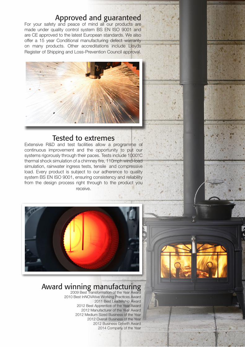
Tested to extremesExtensive R&D and test facilities allow a programme of continuous improvement and the opportunity to put our systems rigorously through their paces. Tests include 1000°C thermal shock simulation of a chimney fire, 110mph wind-load simulation, rainwater ingress tests, tensile and compressive load. Every product is subject to our adherence to quality system BS EN ISO 9001, ensuring consistency and reliability from the design process right through to the product you
receive.
Approved and guaranteedFor your safety and peace of mind all our products are made under quality control system BS EN ISO 9001 and are CE approved to the latest European standards. We also offer a 15 year Conditional manufacturing defect warranty on many products. Other accreditations include Lloyds Register of Shipping and Loss-Prevention Council approval.
Award winning manufacturing2009 Best Transformation of the Year Award
2010 Best InNOVAtive Working Practices Award2011 Best Leadership Award
2012 Best Apprentice of the Year Award2012 Manufacturer of the Year Award
2012 Medium Sized Business of the Year2012 Overall Business of the Year
2012 Business Growth Award2014 Company of the Year
4
Where used for solid fuel and oil applications where the flue gas temperature is greater than 250°C, the ventilated support components must be used as detailed on page 17.
For T600 temperature applications, NOVA® can only be applied where the chimney passes through non-combustible floors and where the chimney is enclosed throughout its length within a ventilated non-combustible enclosure or shaft. For more information, please contact SFL Technical Dept.
For condensing (WET) / positive pressure applications, where the flue gas temperature will not exceed 200°C at a maximum positive pressure of 200Pa (P1), an optional seal can be fitted to the NOVA® product as detailed on page 24.
For condensing applications it is important that any sloping runs are angled not less than 3° where head room is an issue or preferably 5° from the horizontal. Drainage components should also be incorporated into the system to allow condensate removal to a suitable drain or gully. Tees and elbows are provided within the NOVA® range to facilitate a 3° or 5° incline from the horizontal.
Table 1 - Chimney designation to BS EN 1856-1
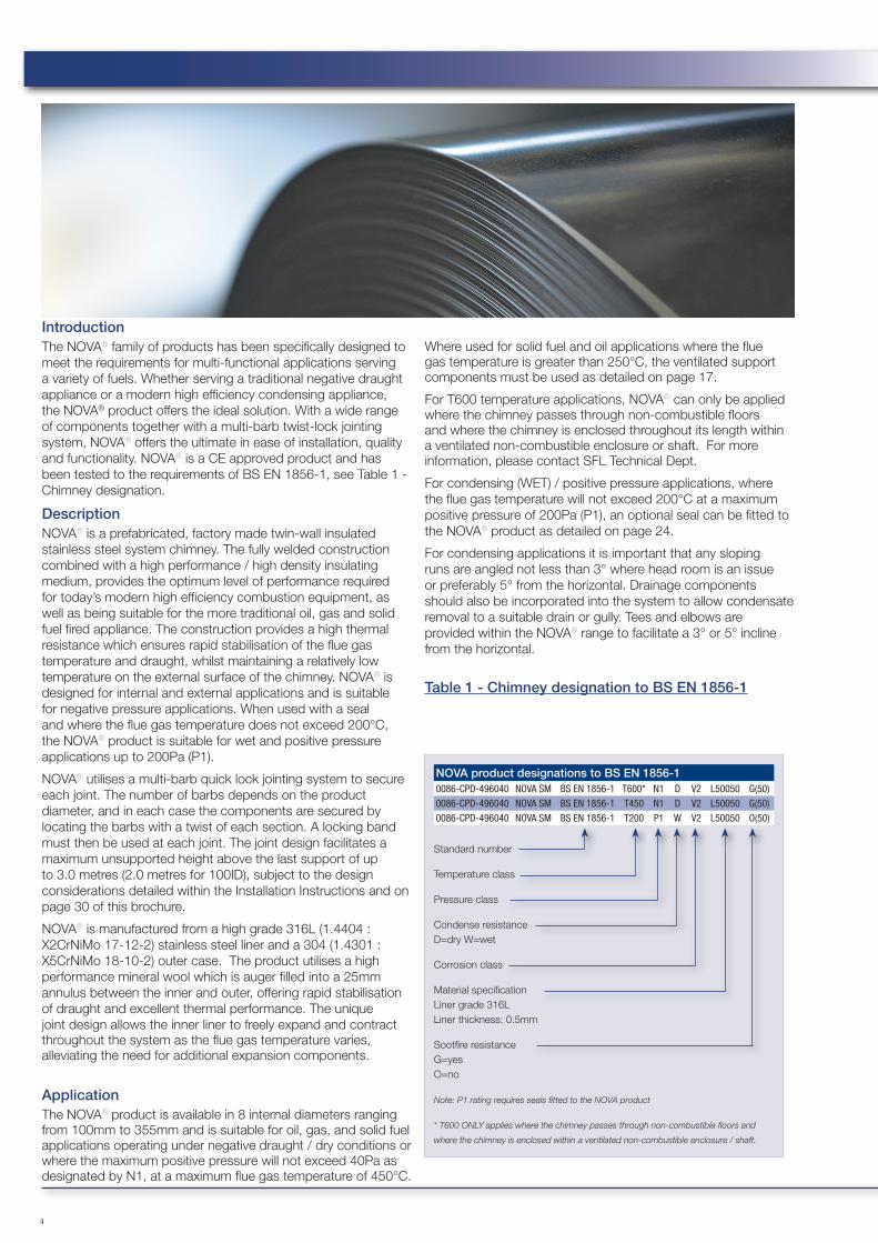
IntroductionThe NOVA® family of products has been specifically designed to meet the requirements for multi-functional applications serving a variety of fuels. Whether serving a traditional negative draught appliance or a modern high efficiency condensing appliance, the NOVA® product offers the ideal solution. With a wide range of components together with a multi-barb twist-lock jointing system, NOVA® offers the ultimate in ease of installation, quality and functionality. NOVA® is a CE approved product and has been tested to the requirements of BS EN 1856-1, see Table 1 - Chimney designation.
DescriptionNOVA® is a prefabricated, factory made twin-wall insulated stainless steel system chimney. The fully welded construction combined with a high performance / high density insulating medium, provides the optimum level of performance required for today’s modern high efficiency combustion equipment, as well as being suitable for the more traditional oil, gas and solid fuel fired appliance. The construction provides a high thermal resistance which ensures rapid stabilisation of the flue gas temperature and draught, whilst maintaining a relatively low temperature on the external surface of the chimney. NOVA® is designed for internal and external applications and is suitable for negative pressure applications. When used with a seal and where the flue gas temperature does not exceed 200°C, the NOVA® product is suitable for wet and positive pressure applications up to 200Pa (P1).
NOVA® utilises a multi-barb quick lock jointing system to secure each joint. The number of barbs depends on the product diameter, and in each case the components are secured by locating the barbs with a twist of each section. A locking band must then be used at each joint. The joint design facilitates a maximum unsupported height above the last support of up to 3.0 metres (2.0 metres for 100ID), subject to the design considerations detailed within the Installation Instructions and on page 30 of this brochure.
NOVA® is manufactured from a high grade 316L (1.4404 : X2CrNiMo 17-12-2) stainless steel liner and a 304 (1.4301 : X5CrNiMo 18-10-2) outer case. The product utilises a high performance mineral wool which is auger filled into a 25mm annulus between the inner and outer, offering rapid stabilisation of draught and excellent thermal performance. The unique joint design allows the inner liner to freely expand and contract throughout the system as the flue gas temperature varies, alleviating the need for additional expansion components.
ApplicationThe NOVA® product is available in 8 internal diameters ranging from 100mm to 355mm and is suitable for oil, gas, and solid fuel applications operating under negative draught / dry conditions or where the maximum positive pressure will not exceed 40Pa as designated by N1, at a maximum flue gas temperature of 450°C.
NOVA product designations to BS EN 1856-10086-CPD-496040 NOVA SM BS EN 1856-1 T600* N1 D V2 L50050 G(50)0086-CPD-496040 NOVA SM BS EN 1856-1 T450 N1 D V2 L50050 G(50)0086-CPD-496040 NOVA SM BS EN 1856-1 T200 P1 W V2 L50050 O(50)
Standard number
Temperature class
Pressure class
Condense resistance D=dry W=wet
Corrosion class
Material specification Liner grade 316L Liner thickness: 0.5mm
Sootfire resistance G=yes O=no
Note: P1 rating requires seals fitted to the NOVA product
* T600 ONLY applies where the chimney passes through non-combustible floors and
where the chimney is enclosed within a ventilated non-combustible enclosure / shaft.

Typical Domestic Installation
5
Design & Quote in SecondsCreate unique quotes for stove installations with the SFL UK App! Available for iPhone/iPad & Android or use on your PC internet by visiting app.sflchimneys.com
SFL UKis free to download and generates list-price quotes on the spot. Using your unique quote reference, your SFL supplier can then provide a full bill of materials and a price-breakdown.
Storm Collar
Adjustable Flashing
Roof/Rafter Support
Ventilated Firestop
30min Fire-Rated Enclosure
D5 Ventilated Ceiling Support
Tapered Starter Length
Adaptor to Twin Wall
45° Elbow
Wall Band
25mm Insulation
Twist Lock
135° Tee
Wall Sleeve
Wall Support
Wall Trim Plate

6
The ideal companion to Biomass heating appliancesHeralded as one of the most cost-effective, renewable and carbon-lean heat sources, wood, woodchip and wood pellet boilers are becoming increasingly popular throughout the UK & Europe.
NOVA® chimney system has been designed with the latest biomass plant in mind. From small household systems to full-scale public buildings, NOVA® is supported by a growing range of bespoke components for use with HETAS approved solid wood-based fuels.
BIOMASS
Photos courtesy of Evogreen Ltd, Suffolk
7
150mm
846mm
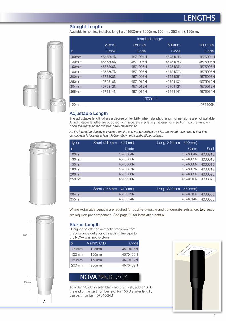
Straight LengthAvailable in nominal installed lengths of 1500mm, 1000mm, 500mm, 250mm & 120mm.
Installed Length
120mm 250mm 500mm 1000mm
ø Code Code Code Code100mm 4575304N 4571904N 4575104N 4575004N130mm 4575305N 4571905N 4575105N 4575005N150mm 4575306N 4571906N 4575106N 4575006N180mm 4575307N 4571907N 4575107N 4575007N200mm 4575308N 4571908N 4575108N 4575008N250mm 4575310N 4571910N 4575110N 4575010N304mm 4575312N 4571912N 4575112N 4575012N355mm 4575314N 4571914N 4575114N 4575014N
1500mm
150mm 4579906N
Adjustable LengthThe adjustable length offers a degree of flexibility when standard length dimensions are not suitable. All adjustable lengths are supplied with separate insulating material for insertion into the annulus once the installed length has been determined.
As the insulation density is installed on site and not controlled by SFL, we would recommend that this component is located at least 300mm from any combustible material.
Type Short (210mm - 320mm) Long (310mm - 500mm)
ø Code Code Seal100mm 4576604N 4574604N 4006310130mm 4576605N 4574605N 4006313150mm 4576606N 4574606N 4006315180mm 4576607N 4574607N 4006318200mm 4576608N 4574608N 4006320250mm 4576610N 4574610N 4006325
Short (255mm - 410mm) Long (330mm - 550mm)304mm 4576612N 4574612N 4006530355mm 4576614N 4574614N 4006535
Where Adjustable Lengths are required for positive pressure and condensate resistance, two seals
are required per component. See page 29 for installation details.
Starter LengthDesigned to offer an aesthetic transition fromthe appliance outlet or connecting flue pipe tothe NOVA chimney system.
ø A (mm) O.D Code130mm 125mm 4570405N
150mm 150mm 4570406N
180mm 175mm 4570407N
200mm 200mm 4570408N
LENGTHS
To order NOVA® in satin black factory-finish, add a “B” to the end of the part number. e.g. for 150ID starter length, use part number 4570406NB
NOVA BLACK

8
250m
m15
0mm
100m
m
80mm
500m
m
150mm
A
Adjustable Slip LengthAn alternative to conventional adustable lengths, this component consists of a length which will fit inside an existing chimney length and a cover jacket to be insulated by the installer with the insulation provided.
A distance of 300mm to combustible materials should be observed when installing this component.
N.B. This component does not form a complete length of twin-wall chimney (as do our regular adjustable lengths) and requires a standard straight length of the same diameter. See adjustment range data on P.28
ø Code
100mm 4570004N
130mm 4570005N
150mm 4570006N
180mm 4570007N
200mm 4570008N
250mm 4570010N
Inspection Length – (N1/D)Use to provide access for inspection or cleaning via an insulated lockable door. This component is only suitable for negative pressure/dry non-condensing applications. For positive pressure or wet condensing applications use the P1/W inspection length.
ø Code
100mm N/A
130mm 4576205N
150mm 4576206N
180mm 4576207N
200mm 4576208N
250mm 4576210N
304mm 4576212N
355mm 4576214N
Inspection Length – (P1/W)Use to provide access for inspection and cleaning. To be used for positive pressure and wet systems where the flue gases are likely to condensate within the chimney system. Suitable for flue gas temperatures up to 200°C at 200Pa.
Dims (mm)
ø A B Code
100mm 206 70 4576304N
130mm 206 80 4576305N
150mm 215 100 4576306N
180mm 215 100 4576307N
200mm 215 100 4576308N
250mm 215 100 4576310N
304mm 215 100 4576312N
355mm 215 100 4576314N
Duct Drain LengthUsed in an inclined position to trap condensate and permit drainage. It is fitted with a standard stainless steel BSP thread connection and incorporates an internal back flow dam.
ø Dim A Code
100mm 1" BSP 4576804N
130mm 1" BSP 4576805N
150mm 1" BSP 4576806N
180mm 1" BSP 4576807N
200mm 1" BSP 4576808N
250mm 1" BSP 4576810N
304mm 1" BSP 4576812N
355mm 1" BSP 4576814N
Probe LengthSupplied with a M16 threaded washer and bolt to facilitate a commissioning sampling probe. Cover jacket supplied to cover sampling point when not in use.
ø Code
100mm 4576704N
130mm 4576705N
150mm 4576706N
180mm 4576707N
200mm 4576708N
250mm 4576710N
304mm 4576712N
355mm 4576714N
Damper Length (P1/W)Use for balancing multi-inlet systems and to add resistance. Also suitable for wet systems.
ø Code100mm 4574004N
130mm 4574005N
150mm 4574006N
180mm 4574007N
200mm 4574008N
250mm 4574010N
304mm 4574012N
355mm 4574014N
LENGTHS
9
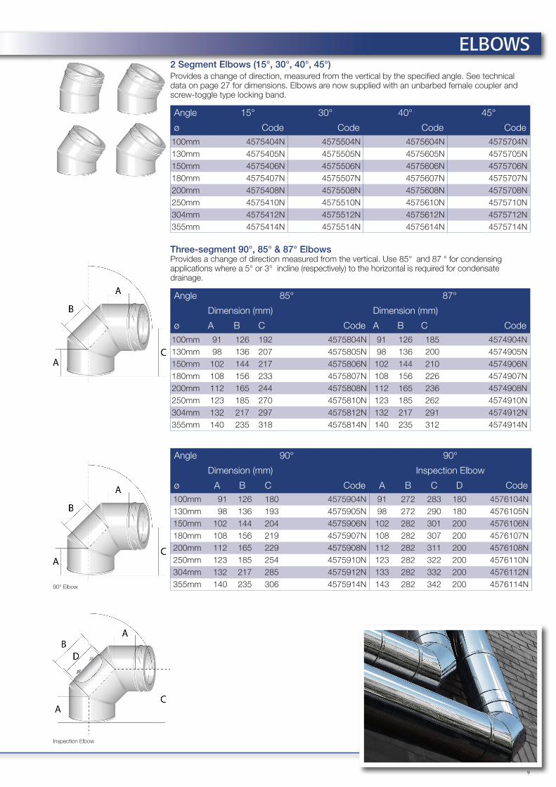
2 Segment Elbows (15°, 30°, 40°, 45°)Provides a change of direction, measured from the vertical by the specified angle. See technical data on page 27 for dimensions. Elbows are now supplied with an unbarbed female coupler and screw-toggle type locking band.
Angle 15° 30° 40° 45°
ø Code Code Code Code100mm 4575404N 4575504N 4575604N 4575704N130mm 4575405N 4575505N 4575605N 4575705N 150mm 4575406N 4575506N 4575606N 4575706N 180mm 4575407N 4575507N 4575607N 4575707N 200mm 4575408N 4575508N 4575608N 4575708N 250mm 4575410N 4575510N 4575610N 4575710N 304mm 4575412N 4575512N 4575612N 4575712N 355mm 4575414N 4575514N 4575614N 4575714N
Three-segment 90°, 85° & 87° ElbowsProvides a change of direction measured from the vertical. Use 85° and 87 ° for condensing applications where a 5° or 3° incline (respectively) to the horizontal is required for condensate drainage.
Angle 85° 87°
Dimension (mm) Dimension (mm)
ø A B C Code A B C Code100mm 91 126 192 4575804N 91 126 185 4574904N130mm 98 136 207 4575805N 98 136 200 4574905N150mm 102 144 217 4575806N 102 144 210 4574906N180mm 108 156 233 4575807N 108 156 226 4574907N200mm 112 165 244 4575808N 112 165 236 4574908N250mm 123 185 270 4575810N 123 185 262 4574910N304mm 132 217 297 4575812N 132 217 291 4574912N355mm 140 235 318 4575814N 140 235 312 4574914N
Angle 90° 90°
Dimension (mm) Inspection Elbow
ø A B C Code A B C D Code100mm 91 126 180 4575904N 91 272 283 180 4576104N130mm 98 136 193 4575905N 98 272 290 180 4576105N150mm 102 144 204 4575906N 102 282 301 200 4576106N180mm 108 156 219 4575907N 108 282 307 200 4576107N200mm 112 165 229 4575908N 112 282 311 200 4576108N250mm 123 185 254 4575910N 123 282 322 200 4576110N304mm 132 217 285 4575912N 133 282 332 200 4576112N355mm 140 235 306 4575914N 143 282 342 200 4576114N
ELBOWS
90° Elbow
Inspection Elbow

10
ø
A
198m
m
250mm
øA
A
A
IncreaserFacilitates an increase in diameter by one step. Constructed with a smooth conical design and welded seams to prevent the build up of condensates
ø Dim A (mm) Code100mm 130 4573604N130mm 150 4573605N150mm 180 4573606N180mm 200 4573706N200mm 250 4573608N
Eccentric IncreaserDesigned specifically for condensing applications to provide an increase in diameter without pooling of condensation in horizontal or inclined runs.
ø A Code150mm 200mm 4570606N180mm 250mm 4570607N200mm 250mm 4570608N200mm 304mm 4570708N250mm 304mm 4570610N250mm 355mm 4570710N
Locking PlugUsed to close off the branch or base of a tee or for use as an access/inspection component.
ø A Code100mm 63 4579104N130mm 63 4579105N150mm 63 4579106N180mm 63 4579107N200mm 63 4579108N250mm 63 4579110N304mm 63 4579112N355mm 63 4579114N
Condensate CollectorUsed at the bottom of a vertical chimney to facilitate the drainage of condensate from the system. Fitted with a stainless steel BSP external thread drain connection.
ø BSP A Code
100mm 1” 63 4576904N130mm 1” 63 4576905N150mm 1” 63 4576906N180mm 1” 63 4576907N200mm 1” 63 4576908N250mm 1” 63 4576910N304mm 1” 63 4576912N355mm 1” 63 4576914N
Draught RegulatorDual action draught regulator suitable for gas, oil and solid fuel applications. Designed to be used with SFL chimney systems where excessive draught is likely to create combustion problems. When used with the NOVA chimney system, the regulator should be applied with the 45785XXN appliance adaptor (in turn located onto the 90° tee branch).
ø Code100mm 3192004130mm 3192005
150mm 3192006
180mm 3192007200mm 3192008250mm 3192010304mm 3192012355mm 3192014
Draught Regulator c/w Pressure ReliefIdeal for use on biomass pellet appliances but also suitable for gas and oil fired appliances where the flue gas temperature will not exceed 400°C. The component also includes an explosion/pressure relief mechanism as required by many biomass appliance manufacturers. Supplied c/w Male Adaptor.Note: This component is supplied with an un-barbed male coupler to allow the Draught Regulator to be positioned plumb vertical at any angle of flue-run.
ø Code150mm 4574206N180mm 4574207N200mm 4574208N250mm 4574210N
SpecificationDiameter (mm)
150/180 200/250
Classification to DIN 4796 4 4
Adjustment Range (Pa) 10-33 4-35
Minimum Opening Pressure (mbar) 6 6
Maximum Flue Gas Temperature (°C) 400 400
INCREASERS
TEE COMPONENTS

11
90° Equal TeeUsed as the entry to a vertical chimney, or for horizontal header configurations.
90° & 95° Reducing TeeA wide variety of reducing tee combinations are available. Listed here are the most common single-step reductions (i.e. 150mm body, 130mm branch). For a full list of standard reducing tees, please visit www.sflchimneys.com
Angle 90° Reducing Tees 90° 95°
Dimension (mm)
Flue ø A B C Code Branch ø Code Code100mm 300 180 140 4573004N - - -
130mm 330 195 155 4573005N 100mm 4559001 4559501
150mm 350 205 165 4573006N 130mm 4559003 4559503
180mm 380 220 180 4573007N 150mm 4559011 4559511
200mm 400 230 190 4573008N 180mm 4559021 4559521
250mm 450 255 215 4573010N 200mm 4559028 4559528
304mm 500 265 240 4573012N 250mm 4559034 4559534
355mm 550 305 265 4573014N 300mm 4559041 4559541
93° & 95° Equal TeeUsed at the base of a vertical chimney, or for horizontal header configurations. Allows for a 3° or 5° (respectively) incline on wet systems to allow for condensate drainage.
Angle 93° 95°
Dimension (mm) Dimension (mm)
ø A B C Code A B C Code100mm 300 180 140 4573304N 300 180 140 4576404N
130mm 330 195 155 4573305N 330 195 155 4576405N
150mm 350 205 165 4573306N 350 205 165 4576406N
180mm 380 220 180 4573307N 380 220 180 4576407N
200mm 400 230 190 4573308N 400 230 190 4576408N
250mm 450 255 215 4573310N 450 255 215 4576410N
304mm 500 286 240 4573312N 500 286 240 4576412N
355mm 550 305 270 4573314N 550 305 270 4576414N
135° TeeUsed at the base of a vertical chimney, or to allow a smooth transition from the horizontal to vertical plain when used with a 45° elbow. The coupler on the branch is unbarbed to allow unlimited rotational adjustment and provided with an adjustable screw-toggle locking band.
Dimension (mm)
With 40° Elbow With 45° Elbow
ø A B C D C D Code100mm 495 325 385 23 385 31 4576504N130mm 495 340 407 22 407 30 4576505N150mm 495 375 439 29 439 38 4576506N180mm 745 420 481 37 481 47 4576507N200mm 745 450 509 43 509 53 4576508N250mm 745 520 577 55 577 65 4576510N304mm 745 585 625 73 625 84 4576512N355mm 995 650 688 84 688 96 4576514N
TEES90° Equal Tee
90° ReducingTee 95° ReducingTee
93° & 95° Equal Tee
135° Tee
135° Tee & Elbow
Flue ø Flue ø
Bra
nch
ø
Bra
nch
ø

12
A
O.D.
O.D. (B)
A
A
B
AB
A
113m
m
Appliance AdaptorUsed to connect the appliance outlet to the NOVA® chimney system. This adaptor is also used for connection of the draught regulator to the branch of a 90° tee. Also used to connect NOVA® to Sigma single wall connecting flue pipe.
ø Dim A (mm) O.D. Code100mm 63 98 4578504N130mm 63 128 4578505N150mm 63 148 4578506N180mm 63 178 4578507N200mm 63 198 4578508N250mm 63 248 4578510N304mm 63 298 4578512N355mm 63 348 4578514N
Appliance Adaptor (Imperial)Used for connection to appliances with imperial or equivalent spigots.
ø A B Code130mm 63 125mm 4578405N180mm 63 175mm 4578407N
Appliance Increaser AdaptorUsed to increase the appliance outlet size by one diameter.
ø O.D. (A) Code100mm 80mm 4579404N150mm 123mm 4579505N150mm 130mm 4579405N
Supra to NOVA® AdaptorUsed to connect from the SUPRA chimney system or for use as an appliance adaptor
ø Code
100mm 4579604N130mm 4579605N150mm 4579606N180mm 4579607N200mm 4579608N250mm 4579610N304mm 4579612N355mm 4579614N
NOVA® to Supra AdaptorDesigned to facilitate connection from the NOVA® to Supra chimney system.
ø Code100mm 4579704N130mm 4579705N150mm 4579706N180mm 4579707N200mm 4579708N250mm 4579710N304mm 4579712N355mm 4579714N
NOVA® to Flex AdaptorUsed to connect the NOVA® product to a flexible flue liner. Supplied with clamp band for ease of installation.
ø A B Code100mm 113 96 4573404N130mm 138 121 4573405N150mm 163 146 4573406N180mm 190 171 4573407N200mm 213 196 4573408N250mm 263 246 4573410N304mm 313 296 4573412N355mm 363 346 4573414N
Flex to NOVA® AdaptorUsed to connect a flexible flue liner to NOVA®, e.g. where a masonry chimney has been capped within a roof void. Supplied with clamp band for ease of installation.
ø A B Code100mm 113 96 4573204N130mm 138 121 4573205N150mm 163 146 4573206N180mm 190 171 4573207N200mm 213 196 4573208N250mm 263 246 4573210N304mm 313 296 4573212N355mm 363 346 4573214N
ADAPTORS
Clamp band with screw-toggle adjustment
SELFLEX®
Adaptor to NOVA®
Flex adaptor installation example
13
mm
min 5° - max 90°
°
Standard Catalogue Dimension Apply(Unless Specified)
Flue Size - SpecifyOD Specify in mm
°
mm
mm
Sta
ndar
d C
atal
ogue
Dim
ensi
ons
App
ly(U
nles
s S
peci
fied)
Standard CatalogueDimensions Apply(Unless Specified)
Specify Angle
Flue Size - Specify
Flue
Siz
e -
Spe
cify
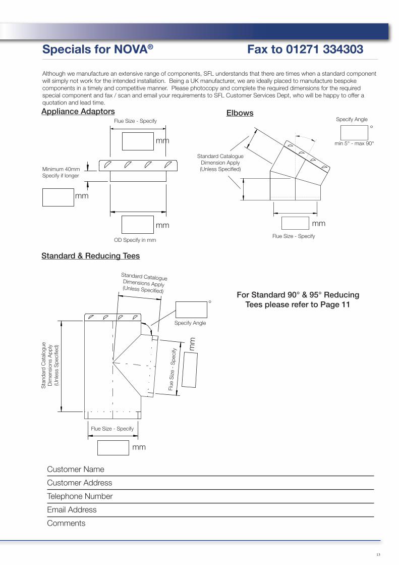
For Standard 90° & 95° Reducing Tees please refer to Page 11
Flue Size - Specify Specify Angle
mm
mm
mm
Minimum 40mmSpecify if longer
Specials for NOVA® Fax to 01271 334303
Although we manufacture an extensive range of components, SFL understands that there are times when a standard component will simply not work for the intended installation. Being a UK manufacturer, we are ideally placed to manufacture bespoke components in a timely and competitive manner. Please photocopy and complete the required dimensions for the required special component and fax / scan and email your requirements to SFL Customer Services Dept, who will be happy to offer a quotation and lead time.
Customer Name
Customer Address
Telephone Number
Email Address
Comments
Appliance Adaptors Elbows
Standard & Reducing Tees

14
Roof / Rafter SupportProvided with adjustable and locking gimbal plates to permit a chimney to be supported on roof joists, trussed rafters etc. Maximum suspended chimney length supported is 6.0 metres and maximum total length supported is 9.0 metres.
ø A B Code100mm 418 310 7072610
130mm 448 340 7072613
150mm 468 360 7072615
180mm 498 390 7072618
200mm 518 410 7072620
250mm 568 460 7072625
304mm 618 510 7072630
355mm 668 560 7072635
Universal Split BandOffers lateral support to the chimney system. The split band has adjustable brackets to allow the support of inclined runs. Design for use with M10 Drop Rod.
ø Code100mm 3123150130mm 3123180150mm 3123200180mm 3123230200mm 3123250250mm 3123300304mm 3123350355mm 3123400
Single Wall to NOVA® Anchor PlateDesigned to be used when connecting NOVA® to a lintel or pre-cast chamber. A short section of liner projects a nominal 32mm through the bottom of the plate. Installed length “H” is 40mm while “E” is 27mm and there are 8 x 11mm fixing holes at the centres shown in the table below. Manufactured in stainless steel. Maximum Load: 13m
ø A B C Code
100mm 281 196 252 4577504N130mm 311 226 282 4577505N150mm 331 246 302 4577506N180mm 360 275 331 4577507N200mm 384 299 355 4577508N250mm 432 345 403 4577510N304mm 482 395 453 4577512N355mm 533 446 504 4577514N
For loading details and maximum distance between supports, please see page 28
Support length (Strut/Guy Attachment)A 117mm installed length which incorporates a plate located 33mm from the bottom edge and features slotted holes for rotational adjustment. This component also doubles as a strut / guy attachment length offering anchoring points to which guys, or preferably rigid stays can be secured using M8 nuts and bolts. Manufactured from stainless steel.
ø Code100mm 4578804N130mm 4578805N150mm 4578806N180mm 4578807N200mm 4578808N250mm 4578810N304mm 4578812N
SUPPORT COMPONENTS
C
B
A
B
A
H
E
15
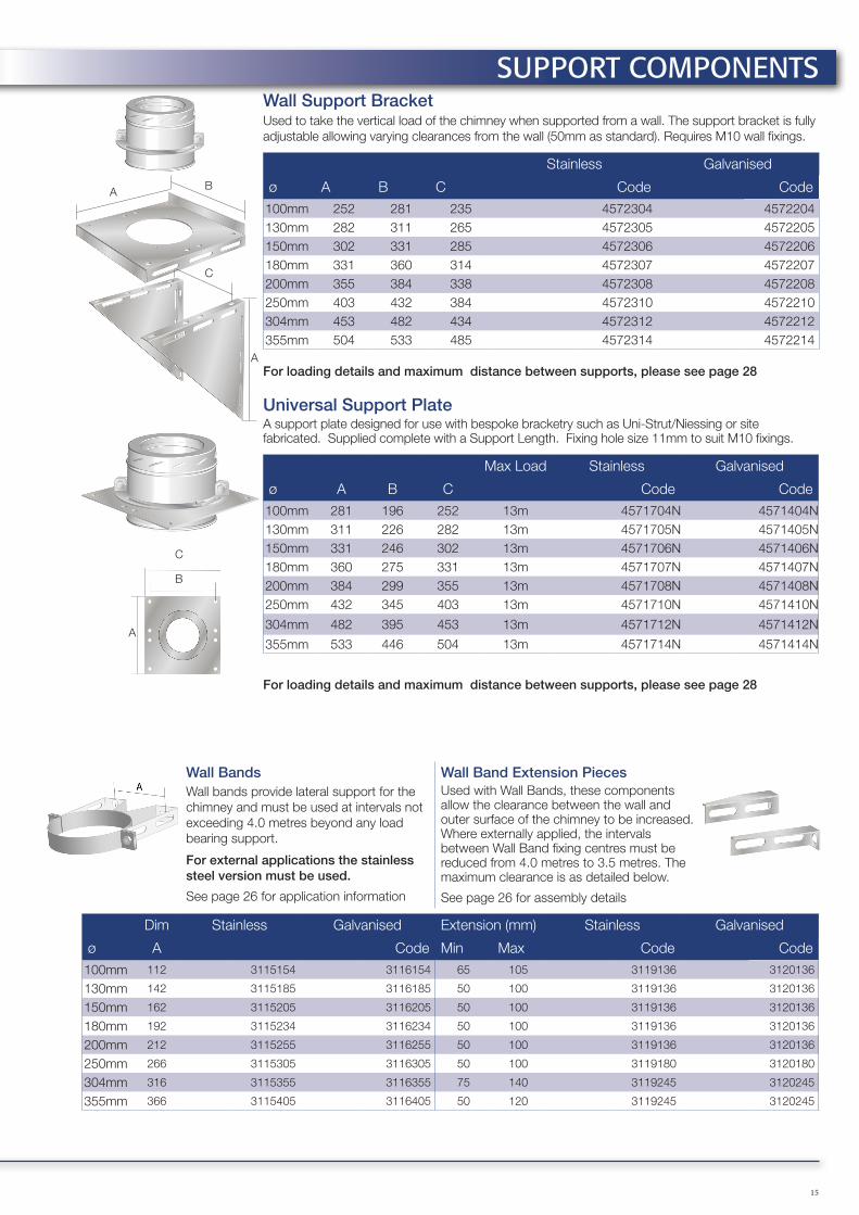
Wall Support BracketUsed to take the vertical load of the chimney when supported from a wall. The support bracket is fully adjustable allowing varying clearances from the wall (50mm as standard). Requires M10 wall fixings.
Stainless Galvanised
ø A B C Code Code100mm 252 281 235 4572304 4572204130mm 282 311 265 4572305 4572205150mm 302 331 285 4572306 4572206180mm 331 360 314 4572307 4572207200mm 355 384 338 4572308 4572208250mm 403 432 384 4572310 4572210304mm 453 482 434 4572312 4572212355mm 504 533 485 4572314 4572214
For loading details and maximum distance between supports, please see page 28
Universal Support PlateA support plate designed for use with bespoke bracketry such as Uni-Strut/Niessing or site fabricated. Supplied complete with a Support Length. Fixing hole size 11mm to suit M10 fixings.
Max Load Stainless Galvanised
ø A B C Code Code100mm 281 196 252 13m 4571704N 4571404N130mm 311 226 282 13m 4571705N 4571405N150mm 331 246 302 13m 4571706N 4571406N180mm 360 275 331 13m 4571707N 4571407N200mm 384 299 355 13m 4571708N 4571408N250mm 432 345 403 13m 4571710N 4571410N
304mm 482 395 453 13m 4571712N 4571412N
355mm 533 446 504 13m 4571714N 4571414N
For loading details and maximum distance between supports, please see page 28
Wall BandsWall bands provide lateral support for the chimney and must be used at intervals not exceeding 4.0 metres beyond any load bearing support.
For external applications the stainless steel version must be used.
See page 26 for application information
Wall Band Extension PiecesUsed with Wall Bands, these components allow the clearance between the wall and outer surface of the chimney to be increased. Where externally applied, the intervals between Wall Band fixing centres must be reduced from 4.0 metres to 3.5 metres. The maximum clearance is as detailed below.
See page 26 for assembly details
Dim Stainless Galvanised Extension (mm) Stainless Galvanised
ø A Code Min Max Code Code100mm 112 3115154 3116154 65 105 3119136 3120136
130mm 142 3115185 3116185 50 100 3119136 3120136
150mm 162 3115205 3116205 50 100 3119136 3120136
180mm 192 3115234 3116234 50 100 3119136 3120136
200mm 212 3115255 3116255 50 100 3119136 3120136
250mm 266 3115305 3116305 50 100 3119180 3120180
304mm 316 3115355 3116355 75 140 3119245 3120245
355mm 366 3115405 3116405 50 120 3119245 3120245
SUPPORT COMPONENTS
C
BA
A
C
B
A

16
Wall BandCan also be used as a conventional Wall Band
ø A Code100mm 220 3109510130mm 250 3109513150mm 270 3109515180mm 300 3109518200mm 320 3109520250mm 370 3109525
Extension BracketsAvailable in Short, Medium and Long versions to provide the required distance from wall
Size A CodeShort 324 31093STMedium 395 31093MDLong 600 31093LG
Bracing BracketsAvailable in three sizes to suit Extension Brackets (above)
Size A (mm) CodeShort 521 31094STMedium 557 31094MDLong 571 31094LG
Support lengthCan be used with the Support Plate and Bracing Brackets as part of a loadbearing wall support
ø Code
100mm 4578804N130mm 4578805N150mm 4578806N180mm 4578807N200mm 4578808N250mm 4578810N
Support PlateFor use with the support length and cantilever framework to create a loadbearing wall support
ø A Code100mm 220 3109710130mm 250 3109713150mm 270 3109715180mm 300 3109718200mm 320 3109720250mm 370 3109725
SUPPORT COMPONENTSPick & Mix Support SystemAn alternative system to SFL’s conventional support components, designed to offer a flexible solution to the individual support requirements of domestic installations. Available for chimney diameters up to 250mm, each part is ordered separately to comprise the bracket required.
The Wall Band is designed to offer 50mm clearance from the outer case of the chimney to the back plate of the bracket. Where required, Extension Brackets can be used to increase this distance to within the specified dimensions as detailed within the table below. The bracket must be installed plumb and fixed to the structure using adequate fixings. The Wall Bracket is fitted with two M6 Nut Inserts to allow easy fixing of the two Support Band Rings using the M6 bolts and washers provided.
ø MaximumSHORT
MaximumMEDIUM
MaximumLONG
Minimumwith Arms
Minimum withoutExtension Arms
100mm 249 320 525 55mm 50mm
130mm 234 305 510 55mm 50mm
150mm 224 295 500 55mm 50mm
180mm 209 280 485 55mm 50mm
200mm 199 270 475 55mm 50mm
250mm 174 245 450 55mm 50mm
Extension Brackets are designed to extend the clearance from the outer case of the chimney to the structure. The Extension Brackets have been designed to slide through on the inside of the Wall band and can be cut to length if required.Maximum/minimum distances for wall bands and extension arms:
Maximum extension Loading
ø SHORT MEDIUM LONG Max Loading (m)
100mm 124 195 400 8.6
130mm 94 165 370 7.0
150mm 74 145 350 6.2
180mm N/A 115 320 5.2
200mm N/A 95 300 4.8
250mm N/A N/A 250 3.9
Bracing Brackets can be attached to the Extension Brackets along with the Support Plate and Universal Split Band to pro-duce a Wall Support for vertical loading.
Pick & Mix Wall Support Arrangement
Please refer to separate Pick & Mix Support literature for full installation instructions
17
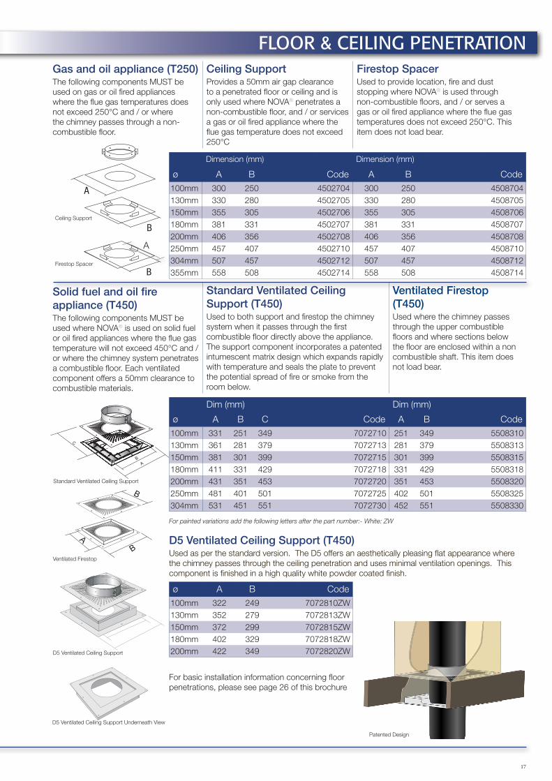
Ceiling SupportProvides a 50mm air gap clearance to a penetrated floor or ceiling and is only used where NOVA® penetrates a non-combustible floor, and / or services a gas or oil fired appliance where the flue gas temperature does not exceed 250°C
Firestop SpacerUsed to provide location, fire and dust stopping where NOVA® is used through non-combustible floors, and / or serves a gas or oil fired appliance where the flue gas temperatures does not exceed 250°C. This item does not load bear.
Dimension (mm) Dimension (mm)
ø A B Code A B Code100mm 300 250 4502704 300 250 4508704130mm 330 280 4502705 330 280 4508705150mm 355 305 4502706 355 305 4508706180mm 381 331 4502707 381 331 4508707200mm 406 356 4502708 406 356 4508708250mm 457 407 4502710 457 407 4508710304mm 507 457 4502712 507 457 4508712355mm 558 508 4502714 558 508 4508714
Standard Ventilated Ceiling Support (T450)Used to both support and firestop the chimney system when it passes through the first combustible floor directly above the appliance. The support component incorporates a patented intumescent matrix design which expands rapidly with temperature and seals the plate to prevent the potential spread of fire or smoke from the room below.
Ventilated Firestop (T450)Used where the chimney passes through the upper combustible floors and where sections below the floor are enclosed within a non combustible shaft. This item does not load bear.
Dim (mm) Dim (mm)
ø A B C Code A B Code100mm 331 251 349 7072710 251 349 5508310130mm 361 281 379 7072713 281 379 5508313150mm 381 301 399 7072715 301 399 5508315180mm 411 331 429 7072718 331 429 5508318200mm 431 351 453 7072720 351 453 5508320250mm 481 401 501 7072725 402 501 5508325304mm 531 451 551 7072730 452 551 5508330
D5 Ventilated Ceiling Support (T450)Used as per the standard version. The D5 offers an aesthetically pleasing flat appearance where the chimney passes through the ceiling penetration and uses minimal ventilation openings. This component is finished in a high quality white powder coated finish.
ø A B Code100mm 322 249 7072810ZW130mm 352 279 7072813ZW150mm 372 299 7072815ZW180mm 402 329 7072818ZW200mm 422 349 7072820ZW
Gas and oil appliance (T250) The following components MUST be used on gas or oil fired appliances where the flue gas temperatures does not exceed 250°C and / or where the chimney passes through a non-combustible floor.
Solid fuel and oil fire appliance (T450)The following components MUST be used where NOVA® is used on solid fuel or oil fired appliances where the flue gas temperature will not exceed 450°C and /or where the chimney system penetrates a combustible floor. Each ventilated component offers a 50mm clearance to combustible materials.
For painted variations add the following letters after the part number:- White: ZW
FLOOR & CEILING PENETRATION
A
B
B
B
A
A
C
B
A
B
Ceiling Support
Firestop Spacer
A
B
B
A
A
C
B
Standard Ventilated Ceiling Support
Ventilated Firestop
D5 Ventilated Ceiling Support
D5 Ventilated Ceiling Support Underneath View
Patented Design
For basic installation information concerning floor penetrations, please see page 26 of this brochure

18
600mm
600mm
1.5m
1.5m
1.5m
1.5m
1.5m
600mm
600mm
600mm
2000mmA
B B
A
If “A” is less than 1.5m, “B” must be not less than 600mm
Domestic Gas Installation Termination HeightsFigs 5.1-5.3 (opposite) illustrate terminal siting for common installation situations for further requirements, refer to BS5440-1
No part of the flue outlet shall be less than 1.5 metres measured horizontally to the roof surface, or any wall. Where the flue terminates above the ridge, it shall do so by not less than 600mm, other than where the flue terminates with a purpose designed ridge terminal.
The chimney should not penetrate the dark shaded area.
Fig. 5.1 Fig. 5.2 Fig. 5.3
A Gas TerminalThe Gas Terminal is available from 100mm to 355mm internal diameter.
ø A B Code
100mm 236 118 4552404
130mm 236 118 4552405
150mm 267 118 4552406
180mm 293 220 4552407
200mm 320 220 4552408
250mm 368 220 4552410
304mm 421 220 4552412
355mm 469 220 4552414
TERMINALS
Solid Fuel Chimney Termination Heights.Chimney termination heights and positions are subject to current Building Regulations and National Standards. The illustrations are based Approved Document J of the Building Regulations for solid fuel and oil fired appliances. Domestic natural gas fired appliances are governed by BS5440-1. All other European countries are governed by their own Regulations, however reference can be made to the countries National Annex of BS EN 15287-1 for individual requirements.
If the chimney serves an oil fired appliance with a pressure jet burner, the chimney must discharge a minimum 600mm above the roof penetration point, or any adjacent structure, if it is within 750mm. It must also be at least 600mm from any opening into the building and 300mm from any combustible material.
Where used with an oil fired appliance with a vaporising burner, termination must comply with the details in this diagram
Minimum distance measured from the top of the chimney construction, excluding any pot or terminal:
A 2.3 metres horizontally clear of the roof surface, e.g. if the roof pitch is 45°, then the chimney should project 2.3 metres above it.
B 1.0 metre, provided A is satisfied, or 600mm above the ridge if G is less than 600mm.
C 1.0 metre above the top of any flat roof, and the top of any openable roof light, dormer window or ventilator, etc., if it is located within 2.3 metres.
D/E If D is less than 2.3 metres, E shall be not less than 600mm.
F 600mm above the ridge.
G If G is within 600mm of the ridge then B shall be 600mm above the ridge.
Fig. 5: Termination heights, not including cowl or terminal
Flue Outlets for Oil-Fired AppliancesFlue termination heights for oil-fired appliances must comply with BS EN 15287-1. The table below explains minimum distances in most common situations with refer-ence to FIG. 5. For further information, please refer to the relevant National annexe.
Pressure Jet Vapourising
B Above the highest point at which the chimney crosses the roof
600mm 1000mm
D From an adjacent structure 750mm 2300mm
E Above the height of an adjacent structure at the following distances from the edge of the flue: Pressure Jet: 750mm; Vapourising: 2300mm
600mm 1000mm

Round Top
19
NOVA® Mini EUROCOWL
Rain Cap
Top StubThe terminal offers the least resistance to flue gases and is ideal for solid fuel and oil fired appliances, providing there is drainage at the base of the chimney.
Top Stub With MeshIdeally suited for condensing/high efficiency appliances. Not suitable for solid fuel application or where there is no provision for drainage below termination.
Dimension (mm) Dimension (mm)
ø A Code A Code100mm 100 4570804 100 4570704130mm 100 4570805 100 4570705150mm 100 4570806 100 4570706180mm 100 4570807 100 4570707200mm 100 4570808 100 4570708250mm 100 4570810 100 4570710304mm 100 4570812 100 4570712355mm 100 4570814 100 4570714
Rain CapThe Rain Cap offers a degree of protection from rain and is suitable for solid fuel and oil fired appliances.
Round TopThe Round Top offers a greater degree of protection against driving rain and wind, recommended for exposed locations.
Dim (mm) Dim (mm)
ø A B Code A B Code100mm 255 192 4577304 255 155 4573104130mm 255 197 4577305 300 159 4573105150mm 300 204 4577306 300 157 4573106180mm 358 265 4577307 358 189 4573107200mm 402 265 4577308 402 194 4573108250mm 500 300 4577310 500 253 4573110304mm 716 345 4577312 614 288 4573112355mm 716 385 4577314 716 356 4573114
Storm CowlThe Storm Cowl is designed to offer the maximum protection against driving rain and strong winds. Please note that this is not an anti-down draught terminal.
Storm Cowl with MeshNot suitable for solid fuel applications.
ø A B Code A B Code100mm 270 165 4578704 270 165 4578904130mm 294 165 4578705 294 165 4578905150mm 319 165 4578706 319 165 4578906180mm 344 165 4578707 344 165 4578907200mm 369 165 4578708 369 165 4578908250mm 419 210 4578710 419 210 4578910
TERMINALS
Anti-Downdraught
NOVA® Mini EUROCOWLThe NOVA®-specific edition of the most popular anti-downdraught cowl on the market, complete with a factory-fitted NOVA female coupler and locking band for effortless and secure installation.
ø Code150mm 4574506N
20
FLASHINGS & WEATHERING
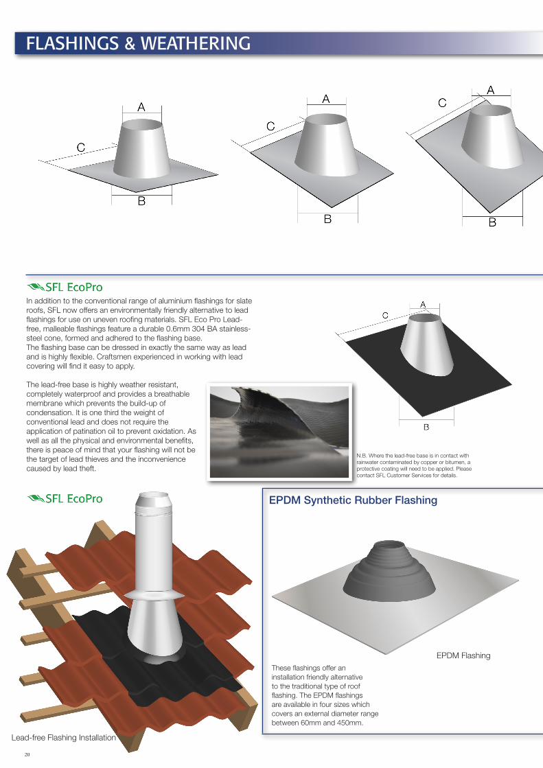
These flashings offer an installation friendly alternative to the traditional type of roof flashing. The EPDM flashings are available in four sizes which covers an external diameter range between 60mm and 450mm.
In addition to the conventional range of aluminium flashings for slate roofs, SFL now offers an environmentally friendly alternative to lead flashings for use on uneven roofing materials. SFL Eco Pro Lead-free, malleable flashings feature a durable 0.6mm 304 BA stainless-steel cone, formed and adhered to the flashing base.The flashing base can be dressed in exactly the same way as lead and is highly flexible. Craftsmen experienced in working with lead covering will find it easy to apply.
The lead-free base is highly weather resistant, completely waterproof and provides a breathable membrane which prevents the build-up of condensation. It is one third the weight of conventional lead and does not require the application of patination oil to prevent oxidation. As well as all the physical and environmental benefits, there is peace of mind that your flashing will not be the target of lead thieves and the inconvenience caused by lead theft.
EPDM Flashing
Lead-free Flashing Installation
EPDM Synthetic Rubber Flashing
N.B. Where the lead-free base is in contact with rainwater contaminated by copper or bitumen, a protective coating will need to be applied. Please contact SFL Customer Services for details.

21
Aluminium FlashingsThe SFL aluminum flashing range offers a competitive alternative to the traditional lead flashing, while still maintaining a traditional design and malleable material. All aluminum flashings require a Storm Collar (p.22).
Flat FlashingFor flat or nearly flat roofs.
5° – 30° Adjustable FlashingFor low pitched roofs.
32° – 45° Adjustable FlashingFor high pitched roofs.
Dimension (mm)
ø A B C Code A B C Code A B C Code100mm 160 250 495 70000006 160 250 495 70053006 160 332 660 70324506130mm 190 280 495 70000007 190 280 495 70053007 190 375 660 70324507150mm 210 300 495 70000009 210 300 660 70053009 210 403 660 70324509180mm 235 325 660 70000010 235 325 660 70053010 235 440 820 70324510200mm 260 350 660 70000011 260 350 660 70053011 260 475 820 70324511250mm 310 400 660 70000012 310 400 660 70053012 310 546 820 70324512304mm 360 450 660 70000013 360 450 820 70053013 360 617 820 70324513355mm 410 500 820 70000014 410 500 965 70053014 410 689 1219 70324514
SFL EcoPro Lead-Free Flashings
5° – 30° Adjustable FlashingFor low pitched roofs.
32° – 45° Adjustable FlashingFor high pitched roofs.
Dimension (mm)
ø A B C Code A B C Code100mm 172 236 900 70053006P 160 306 900 70324506P130mm 205 275 900 70053007P 191 350 900 70324507P150mm 227 300 900 70053009P 211 379 900 70324509P180mm 260 338 900 70053010P 242 425 900 70324510P200mm 282 364 900 70053011P 263 452 900 70324511P250mm 338 428 900 70053012P 314 524 900 70324512P304mm 393 491 900 70053013P 365 597 900 70324513P355mm 448 555 900 70053014P 417 669 900 70324514P
EPDM Synthetic Rubber FlashingThe selection of the correct flashing depends on the outside chimney diameter and intended roof pitch. The table identifies which flashing should be used. Each consists of a malleable aluminium base to which an EPDM rubber cone is sealed. The cone is easily trimmed on site to suit the external diameter of the chimney. Separate installation instructions are provided with every flashing.
øExt Dia (mm)
Roof Pitch
Flashing No.
Cone IndexCut Line
Base Size (A) Code
100mm 150 0-35° 1 E 500X500mm 4901015130mm 180 0-40° 2 E 600x600mm 4901020150mm 200 0-30° 2 F 600x600mm 4901020150mm 200 0-45° 3 C 764x764mm 4901030180mm 230 0-40° 3 D 764x764mm 4901030200mm 250 0-35° 3 F 764x764mm 4901030250mm 300 0-30° 3 I 764x764mm 4901030250mm 300 0-45° 4 A 956x956mm 4901045304mm 350 0-40° 4 C 956x956mm 4901045355mm 400 0-35° 4 F 956x956mm 4901045
The EPDM flashing system will effectively seal and remain pliant over a wide range of external chimney surface temperature extremes from -30° to 115°C. The EPDM cones have also been proven to withstand intermittent surface temperatures of up to 150°C.
EPDM flashings should not be used on single wall chimney systems serving solid fuel appliances or any application where the potential surface temperature of the chimney will exceed the maximum design temperatures details above.
FLASHINGS & WEATHERING
EPDM Flashing Installation

22
A
B
45° Wall Sleeves
Must be used where a 135° tee is used to pass the chimney through an external wall and thus providing a continuous interrupted run through the wall. Provides 50mm clearance as standard. Although designed to suit a 280mm maximum width wall, special sizes can be manufactured to order.
ø A Code100mm 250 3107204130mm 280 3107205150mm 300 3107206180mm 330 3107207200mm 350 3107208250mm 400 3107210304mm 450 3107212355mm 500 3107214
Trim CollarThe trim collar is a polished stainless steel circular collar with a nominal 105mm wide circular flange. This item is used to offer an aesthetic closing ring where a chimney passes through an outside wall.
ø Code100mm 4583204130mm 4583205150mm 4583206180mm 4583207200mm 4583208250mm 4583210304mm 4583212355mm 4583214
Angled Wall Cover RingThe wall cover ring is designed to offer an aesthetic trim around the chimney where it penetrates a wall at an angle. This component is available in five angle variations, 0°-10°, 10°-20°, 20°- 30°, 30°-40° and 40°- 50°.
Wall Penetration Angle
0°-10° 10°-20° 20°-30° 30°-40° 40°-50°
ø A Code Code Code Code Code130mm 156 5571213N 5571313N 5570013N 5570313N 5570213N150mm 146 5571215N 5571315N 5570015N 5570315N 5570215N180mm 131 5571218N 5571318N 5570018N 5570318N 5570218N200mm 121 5571220N 5571320N 5570020N 5570320N 5570220N
FLASHINGS & WEATHERINGAluminium Storm CollarUsed to weather the top of the flashing, supplied with a tube of silicon sealant.
ø A Code100mm 152 255 70 70123406130mm 177 280 70 70123407150mm 202 301 70 70123409180mm 227 330 70 70123410200mm 252 351 70 70123411250mm 302 401 70 70123412304mm 352 451 70 70123413355mm 402 501 70 70123414
NOVA® Stainless Storm CollarThe NOVA® polished stainless steel storm collar is larger and offers a greater degree of protection from weathering. It also adds a superb looking finish to your installation. Highly recommended to complement the EcoPro flashing.
ø A B Code100mm 151 350 4504104130mm 181 380 4504105150mm 201 400 4504106180mm 231 400 4504107200mm 251 450 4504108
280mm

23
Locking BandThe locking band must be used on all joints and are included with each component having a female coupler.
ø Code100mm 4578604130mm 4578605150mm 4578606180mm 4578607200mm 4578608250mm 4578610304mm 4578612355mm 4578614
Locking Band (Screw Toggle)The screw-toggle locking band is provided as standard with the unbarbed female coupler on elbows and 135° tee branches.
ø Code100mm 4578604MT130mm 4578605MT150mm 4578606MT180mm 4578607MT200mm 4578608MT250mm 4578610MT304mm 4578612MT355mm 4578614MT
Joint Sealing Ring (W/P1)This optional component is available for all diameters and is located in the joint groove as detailed in the Installation Instructions and on page 24. This component provides a moisture and gas resistant seal to a pressure of 200Pa as tested to P1 under BS EN 1856-1. The seal would normally be used on applications where there is a likelihood that condensation of the flue gases could result or where the chimney is operating under positive pressure conditions where the flue gas temperature will not exceed 200°C (T200).
Important: SFL seal lubricating compound should be applied around the surface of the seal and interfacing surface prior to making the joint. It is also recommended that the seal is carefully bonded to the fixing groove prior to installation with a suitable silicon adhesive/sealant.
ø Code100mm 4006310130mm 4006313150mm 4006315180mm 4006318200mm 4006320250mm 4006325304mm 4006430355mm 4006435
Joint Sealing Ring (W/P1) for 305mm and 355mm Adjustable Lengths ONLYThese seals are to only be used for the internal slip section of the 305mm and 355mm Adjustable Lengths. All other sizes utilise the standard Joint Sealing Ring as detailed above, Part No. 40063XX in the slip section. See page 29.
ø Code304mm 4006530
355mm 4006535
Seal LubricantThis must be applied around the circumference of the fitted seal to provide a lubricated interface between the seal and the liner when the product is used for positive pressure and wet applications.
Code
250ml 3107500
Only SFL lubricant should be used as it has been specially formulated for use with both silicone and EPDM seal materials. Failure to use SFL lubricant when installing seals in NOVA product will invalidate the product warranty and potentially cause failure of the seal
ACCESSORIES

24
Lateral SupportsWall Bands are available for the lateral support of the installation. These are available in both galvanised steel and stainless steel for external applications. All Wall Bands offer 50mm clearance from the outer case of the flue. Optional Extension Brackets are available to increase this distance up to a maximum of 100mm, see page 15.
Roof / Rafter SupportA roof / rafter support bracket is available where the flue section passes through the roof to termination. This component offers both lateral and vertical loading. For more information, see page 14.
Joint design and construction
A
B
C
D
A – Coupler separatorThe coupler separator is a 1mm dimple which is designed to allow a controlled amount of air to pass across the coupler interface. This limits thermal bridging and heat transfer across the joint as well as reducing the potential for capillary moisture movement.
B – Retrofit sealThe NOVA® product offers a retrofit seal that can be fitted around the inner groove as shown above. The seal facilitates positive pressure and condensate resistance up to 200Pa at a maximum flue gas temperature of 200°C, offering a P1 rating to BS EN 1856-1. For higher pressure capability, please refer to SFL Technical Department.
C – Quick lock jointing systemThe NOVA® joint incorporates a sixteen barb* twist lock coupler system to allow easy and rapid installation of the product. When used with the NOVA® support components the joint will support up to 3.0* metres free standing above the last support. See Installation Instructions or page 19 for further details.
* 100mm internal diameter has 8 barbs and a free standing capability of 2.0 metres, subject to design guidance.
D – Locking BandThe locking band is used to complete the joint and incorporates a simple fixing mechanism to facilitate speed and ease of installation.
Joint AssemblyThe joint is made by fitting the female end over the male end and engaging the joint system by rotating the component clockwise. A locking band is then fitted to finalise the joint, as detailed below.
Fig. 1
Flow
ApprovalsThe NOVA® product has been assessed and CE marked to BS EN 1856-1 to the performance designations as detailed on page 4, Table 1.
NOVA® has also been assessed by the Loss Prevention Council for fire resistance. A fire resistance of two hours can be achieved in accordance with the stability and integrity criteria of BS 476: Part 20 for duct type B.
QualityAll components are manufactured under a quality assurance scheme, certificate No. FM557622, administered by British Standards in accordance with BS EN 9001. In addition SFL operate a CE approved factory production control system as required under the Construction Products Resolution
Installation RegulationsWhere the flue passes through combustible floors it is important that the correct firestop components are used and the correct distance to combustible materials is observed.
All firestop and support components within the NOVA® range are designed to offer a minimum clearance to combustible material of 50mm. In all instances the requirements of the building regulations must be complied with and the appropriate references are: Document J of the DOE Building Regulations, Section F of the Building Standards (Scotland), Section L of the Building Regulations (Northern Ireland). Reference should also be made to the relevant British and European Standards governing the installation of flue and chimney products for the associated fuel and appliance types as detailed:
• Solid Fuel and Oil Fired Applications: BS EN 15287
• Domestic Gas Installations up to 60kW: BS5440: Part 1
• Commercial Gas Installation up to 70kW and 1.8MW (net), the installation should conform to BS 6644
For further information, please refer to Installation Instructions in this document.
SYSTEM DETAILS

25
Note: In the UK, connection to an appliance which is not connected to a fuel supply, may be carried out by a competent person. However connection to an appliance that is connected to a fuel supply must be carried out by an approved and registered heating engineer, e.g. Gas Safe(Gas) or OFTEC (Oil). For other European countries, reference should be made to EN 15287: Part 1: Chimneys- Design, installation & commissioning of chimneys. Chimneys for non-room-sealed heating appliances. The National Annex NA of EN 15287 should detail the national regulatory requirements for that particular country.
Components
The NOVA® product offers a complete range of prefabricated components allowing total flexibility to meet today’s demanding applications. Installed lengths of 1500mm, 1000mm, 500mm, 250mm and 120mm are available, together with adjustable lengths. A variety of tees, elbows, supports, fixings and firestop components are available as standard throughout the diameter range.
Those components within the range that are manufactured from only single skin, can be vulnerable when exposed to the products of combustion from solid fuel appliances. This is especially true for terminals; however in the majority of cases, an open-ended terminal better suits appliance performance, but it is acknowledged that on occasions, other types of terminal from the range have to be used to reduce rain entry. The condensate collector and locking plug when used on solid fuel are also vulnerable to flue gas by-products, particularly if the chimney is not regularly maintained and cleaned. Such components are considered sacrificial and their life expectancy will vary depending on application, location, maintenance and fuel usage. For this reason, these items are only covered by a twelve month guarantee and not the standard 15 year conditional manufacturing defects warranty.
Life Expectancy and affecting factors
The NOVA® product is manufactured to the highest standard and tested in accordance with EN 1856-1. Under normal operating conditions NOVA® should provide many years service and is provided with a 15 year conditional manufacturing defect warranty. However careful consideration of the following points must be observed to limit the risk of chemical corrosion to the product.
Chemical contamination of combustion air
Under no circumstances should an appliance be located where there is the potential of chemical contamination of the combustion air. Typical examples are de-greasing plants, dry cleaning agents and chemical cleaning products.
Chemical chimney cleaning products
Under no circumstances should chemical chimney cleaning products be used. Only traditional sweeping of the chimney should be employed.
Use only approved solid fuels
Where used on solid fuel, care should be taken to ensure that only high quality fuel is used. SFL do not recommend fuels such as petroleum coke or other fuels containing a blend of petroleum coke. Also some smokeless fuels contain halogens that are released when burnt, forming Hydrochloric and Hydrofluoric Acids. These fuels can lead to premature failure of the chimney system through corrosion. Before burning any fuel, SFL would suggest that written confirmation is obtained to ensure that the fuel is halogen free. Only HETAS Approved solid fuels should be used with SFL products.
It is also important when burning wood that it has not been treated and is free of any potential chemicals such as preservatives, insecticides or pressure treatments. Freshly cut firewood can contain up to 50% moisture, provision must be made to allow the wood to season so that the moisture content is reduced to around 20%. This must be done in a dry environment and can take up to 8 months. Green wood can lead to products like creosote being deposited on the chimney liner and could lead to a chimney fire occurring or premature corrosion / failure of the liner.
BiofuelsNOVA® is suitable for virgin pellet and wood chip biofuel applications where the fuel complies with BS EN 14961 Parts 1-6. Other forms of biofuel when burnt can produce aggressive and corrosive acids, especially at low temperatures, which can lead to premature failure of the product. Written confirmation should be obtained from SFL prior to installing NOVA® for use on any other type of biofuel.
Coastal locationsIt is advised where the chimney is exposed to severe coastal locations that suitable external protection is applied to the outer case of the product. This could be achieved using a specialist protective coating or by having the product professionally painted. It is recommended that only stainless steel components are used for external applications; however where galvanised components are used, they should be adequately protected using an appropriate coating.
Typical installation serving condensing appliances
Calculation and Technical SupportUsing the latest software modelling, SFL can undertake full chimney sizing calculations to BS EN 13384 Parts 1 & 2 as well as advise on other technical matters regarding the Clean Air Act and current regulations regarding chimney systems.
Wall Support Bracket45723XX
SYSTEM DETAILS
26
+
Rear fixing bracket (M10 fixing holes)
back ring
M8 nut inserts
Front securing ring
(OPTIONAL) Side extension brackets to extend Wall Band to 100mm clearance. Must be ordered separately.
+
The maximum supported height above an inlet tee must be no greater than that stated in Table 2
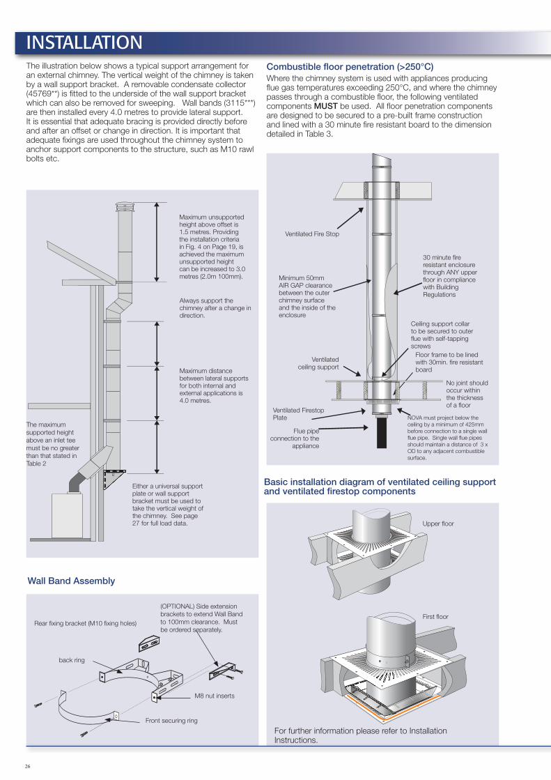
Combustible floor penetration (>250°C)Where the chimney system is used with appliances producing flue gas temperatures exceeding 250°C, and where the chimney passes through a combustible floor, the following ventilated components MUST be used. All floor penetration components are designed to be secured to a pre-built frame construction and lined with a 30 minute fire resistant board to the dimension detailed in Table 3.
Ventilated Fire Stop
Minimum 50mm AIR GAP clearance between the outer chimney surface and the inside of the enclosure
Ventilated ceiling support
30 minute fire resistant enclosure through ANY upper floor in compliance with Building Regulations
NOVA must project below the ceiling by a minimum of 425mm before connection to a single wall flue pipe. Single wall flue pipes should maintain a distance of 3 x OD to any adjacent combustible surface.
Flue pipe connection to the
appliance
No joint should occur within the thickness of a floor
Ceiling support collar to be secured to outer flue with self-tapping screws
Ventilated Firestop Plate
Floor frame to be lined with 30min. fire resistant board
Basic installation diagram of ventilated ceiling support and ventilated firestop components
Upper floor
First floor
For further information please refer to Installation Instructions.
Wall Band Assembly
The illustration below shows a typical support arrangement for an external chimney. The vertical weight of the chimney is taken by a wall support bracket. A removable condensate collector (45769**) is fitted to the underside of the wall support bracket which can also be removed for sweeping. Wall bands (3115***) are then installed every 4.0 metres to provide lateral support. It is essential that adequate bracing is provided directly before and after an offset or change in direction. It is important that adequate fixings are used throughout the chimney system to anchor support components to the structure, such as M10 rawl bolts etc.
Maximum unsupported height above offset is 1.5 metres. Providing the installation criteria in Fig. 4 on Page 19, is achieved the maximum unsupported height can be increased to 3.0 metres (2.0m 100mm).
Always support the chimney after a change in direction.
Maximum distance between lateral supports for both internal and external applications is 4.0 metres.
Either a universal support plate or wall support bracket must be used to take the vertical weight of the chimney. See page 27 for full load data.
INSTALLATION

27
Fig. 2 Fig. 3
A
A
B
C
C
B
Elbows are not loadbearing. Vertical runs after changes of direction should be re-supported appropriately.
Ø (mm)
120mm length15° 30° 40° 45°
B (mm) C (mm) B (mm) C (mm) B (mm) C (mm) B (mm) C (mm)
100 474 78 444 151 413 194 396 214130 501 82 470 158 438 203 420 224150 517 84 485 162 452 208 433 229180 541 87 507 168 473 216 454 238200 556 89 522 172 488 221 467 243250 600 95 563 183 526 235 505 259304 603 95 566 184 530 237 508 260355 643 100 604 194 565 249 542 274
Ø (mm)
250mm length15° 30° 40° 45°
B (mm) C (mm) B (mm) C (mm) B (mm) C (mm) B (mm) C (mm)
100 599 112 556 216 513 278 487 305130 627 115 582 223 538 287 511 315150 643 118 597 227 551 292 525 321180 666 121 620 233 573 299 546 330200 682 123 634 237 587 305 559 335250 725 129 676 248 626 319 597 351304 729 129 679 249 629 320 600 352355 768 134 717 259 665 333 634 366
Ø (mm)
500mm length15° 30° 40° 45°
B (mm) C (mm) B (mm) C (mm) B (mm) C (mm) B (mm) C (mm)
100 841 177 773 341 704 438 664 482130 868 180 799 348 729 447 688 492150 884 182 814 352 743 453 702 498180 908 185 836 358 764 460 722 506200 923 187 851 362 779 465 736 512250 967 193 892 373 817 480 774 528304 970 194 896 374 821 481 777 529355 1010 199 933 384 856 494 811 543
Ø (mm)
1000mm length15° 30° 40° 45°
B (mm) C (mm) B (mm) C (mm) B (mm) C (mm) B (mm) C (mm)
100 1324 306 1206 591 1087 760 1018 836130 1351 310 1232 598 1112 769 1042 846150 1362 312 1247 602 1128 774 1055 851180 1391 315 1269 608 1148 782 1076 860200 1406 317 1284 612 1162 787 1089 865250 1450 322 1325 623 1200 801 1127 881304 1453 323 1329 624 1204 802 1130 882355 1493 328 1366 634 1239 815 1165 897
Elbow offset dimensionsThis data relates to just two elbows used to form an offset as shown in Fig. 2. It also indicates the installed length of the elbow segments. Data is also provided where standard lengths are also incorporated within the offset, see Fig. 3.
15°Ø (mm) A (mm) B (mm) C (mm)100 91 358 47130 98 385 51150 102 401 53180 108 425 56200 112 440 58250 123 484 64304 124 488 64355 134 527 69
30°
Ø (mm) A (mm) B (mm) C (mm)100 91 340 91130 98 366 98150 102 381 102180 108 403 108200 112 418 112250 123 459 123304 124 463 124355 134 500 134
40°Ø (mm) A (mm) B (mm) C (mm)100 91 321 117130 98 346 126150 102 360 131180 108 381 139200 112 396 144250 123 434 158304 124 438 159355 134 473 184
45°Ø (mm) A (mm) B (mm) C (mm)100 91 311 129130 98 335 139150 102 348 144180 108 369 153200 112 382 158250 123 420 174304 124 423 175355 134 457 190
INSTALLATIONVentilated Ceiling Support and Ventilated Firestop
Framing data and dimensionsChimney Size 100 130 150 180 200 250 300
‘A’ Square* 251 281 301 331 351 401 451
* The above dimension does not allow for 30 minute fire rated lining, adjust according to thickness used.
Line frame with 30 minute fire rated board
Note: The fire rated board is required under the test conditions of BS 476: Part 20 where the chimney passes through a representative combustible floor. The purpose is to protect the ceiling void from the effects of radiated heat from the outer case of the chimney where the chimney below the ceiling is engulfed in fire.

28
Wall Support Bracket – technical information
Support configuration and distance between brackets
Closed minimum 50mm
EEE
Open. Must not exceeddim. “E”
ø (mm) A (m) B (m) E (mm)100 30 25 150130 30 25 150150 30 25 150180 20 15 200200 20 15 200250 20 15 220304 20 15 267355 18 12 293
This table details the maximum distance in metres between wall supports, based on the support configuration below.
Closed Open
A
B
Product weightsMaximum weight of NOVA® per metre run installed, excluding support components.
Ø (mm) 100 130 150 180 200 250 304 355kg/m 6.6 8.1 9.2 10.8 11.8 14.5 17.1 19.7
Adjustable Slip-Length with Cover JacketComponent extension limits above an existing length
Combined adjustment range on standard lengths
Extension 250mm 500mm 1000mm
Dia ø Min Max Min Max Min Max Min Max
80 48 295 375 545 550 795 1050 1295
100 48 295 375 545 550 795 1050 1295
130 48 295 375 545 550 795 1050 1295
150 48 295 375 545 550 795 1050 1295
180 48 280 375 530 550 780 1050 1280
200 48 270 375 520 550 770 1050 1270
250 48 245 375 495 550 745 1050 1245
N.B. The Adjustable Slip Length requires a standard length to make a complete component. Adjustable lengths are not loadbearing. A support component should be used immediately above.
IMPORTANT: Wall support loadings are dependent on appropriate wall fixings and the structural integrity of the wall itself.
INSTALLATION
Maximum structural considerations for componentsThe table below shows the maximum number of metres that can be applied to various components. It is essential that these are not exceeded. Where possible components such as inlet tees and inspection lengths should not be vertically loaded, but suspended below a support component, such as the wall support assembly. Where this is unavoidable, refer to the maximum heights in the table below.
Table 2
ComponentsDiameter (mm)
100 130 150 180 200 250 304 355
Inspection length 13m 13m 13m 13m 13m 13m 13m 12m
Ceiling support 6m 6m 6m 6m 6m 6m 6m 6m
Ventilated ceiling support 6m 6m 6m 6m 6m 6m 6m 6m
Anchor plate 13m 13m 13m 13m 13m 13m 13m 13m
Universal support plate 13m 13m 13m 13m 13m 13m 13m 13m
95° & 90° tee 13m 13m 13m 13m 13m 13m 13m 13m
135° tee 13m 13m 13m 13m 13m 13m 13m 13m
29
Detailed installation instructions are provided with all adaptors and terminals, and are also available separately on request, detailed below are key installation requirements for the NOVA® chimney system together with regulatory requirements for the UK. For countries outside of the UK, please refer to your country’s own regulations and national standards.
GeneralThe installation of the NOVA® product must be in accordance with local building regulations and associated National Standards and Codes of Practice. For additional guidance, reference can be made to BS EN 15287-1: Chimneys- Design, installation & commissioning of chimneys. Chimneys for non-room-sealed heating appliances The National Annex NA of EN 15287-1 will detail the national requirements for the particular country.
Every chimney section and fitting shall be used as manufactured for assembly on site without any alteration or cutting. Components are joined with a multi barbed twist lock coupler and secured with a locking band. The only exception are elbows, which are designed to allow full rotation of the component and therefore do not have locking barbs on the female end. All components must be installed with the male coupler facing up as detailed in Fig.1 on Page 24.
NOVA® is suitable for both internal and external applications. Where used on high efficiency condensing appliances, a range of components are available to permit deliberate drainage of condensate, either back to the condensate removal component within the chimney system, or through the heating appliance. No part of the chimney system should be constructed to form an angle greater than 45° from the vertical.
Although components are included that will permit horizontal application, they should only be used for connection to the appliance. Where the system is being used for a condensing application, sections MUST run at an angle not less than 3° - 5° from the horizontal, using tees, elbows and fittings designed for that purpose. Failure to provide adequate drainage could lead to premature failure of the product and seal.
Offsets can be constructed using elbows, lengths and adjustable components available within the system. For full details regarding offset dimensions and heights for various elbow/length combinations see tables on Page 27. According to building regulations: If bends are necessary there must be no more than four in the length of the chimney. The angle of the bend should be no greater than 45° from the vertical, with the exception that 90° factory made bends or tees may be treated as being equal to two 45° bends.
Where an offset is used, the length of chimney between the two elbows MUST NOT exceed 20% of the total vertical length of the chimney.
Where serving solid fuel or oil appliances, any part of the chimney which passes through any room other than that in which the appliance using the chimney is situated, should be protected to prevent damage and accidental location of combustible material against the outer skin. It is a building regulation requirement that ANY factory made insulated chimney should be enclosed where passing through a cupboard, storage space or accessible roof space.
Where used with solid fuel or oil appliances producing flue gas temperatures exceeding 250°C, the clearance at floor / ceiling joists must be established using the ventilated ceiling support and ventilated firestop components. When connecting to a single wall connecting flue or vitreous pipe, at least 425mm of NOVA® must project below the appliance room ceiling before connection is made.
Under no circumstances must there be a joint within the thickness of any floor space. Where passing through a cavity wall a wall sleeve must be used and finished with a suitable trim plate / cover ring.
The internal diameter of the chimney must conform to the requirements of the appliance manufacturers instructions and should not, under any circumstances, be less than the diameter of the appliance outlet unless operational requirements of the appliance can be demonstrated by calculations to BS EN 13384-1
The height of the chimney will depend on the building structure, however a height of 4.5 metres from the top of the appliance outlet to termination is considered the minimum for solid fuel. To prevent excessive cooling of the flue gases when connecting a single wall flue pipe from the stove to the NOVA® chimney, SFL recommends that the length of the single wall pipe is no more than 2.0 metres within the 4.5 metre height recommendation under Building Regulations.
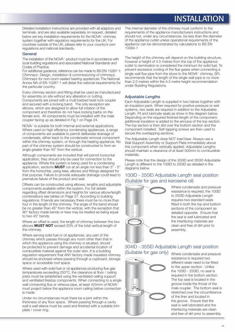
Adjustable LengthsEach Adjustable Length is supplied in two halves together with an insulation pack. When required for positive pressure or wet systems, two seals are required in addition to the Adjustable Length. Fit and lubricate seals as show in the diagram below. Depending on the required finished length of the component, additional insulation is added to the annulus of the top section. The top section is then slid over the bottom section and the component installed. Self-tapping screws are then used to secure the overlapping sections.
The Adjustable Length does NOT load bear. Always use a Wall Support Assembly or Support Plate immediately above this component when vertically applied. Adjustable Lengths should maintain a clearance of at least 300mm to combustible materials.
Please note that the design of the 300ID and 350ID Adjustable Length is different to the 100ID to 250ID as detailed in the diagrams below.
100ID - 250ID Adjustable Length seal position (Suitable for gas and kerosene oil)
304ID - 355ID Adjustable Length seal position (Suitable for gas only)
Where condensate and pressure resistance is required, the 100ID to 250ID Adjustable Length requires two standard seals fitted in both the top and bottom sections of the component as detailed opposite. Ensure that the seal is well lubricated and the interfacing materials are clean and free of dirt prior to assembly.
Where condensate and pressure resistance is required two different seals need to be fitted to the upper section. Unlike the 100ID - 250ID, no seal is required in the bottom section. The top seal is located in the groove inside the throat of the male coupler. The bottom seal is stretched over the circumference of the liner and located in the groove. Ensure that the seal is well lubricated and the interfacing materials are clean and free of dirt prior to assembly.
INSTALLATION

30
Installation criteria for maximum freestanding height
Height includes any termination
Max. 3.0 metre unsupported length (2.0m for 100mm diameter NOVA®) providing:
a There are no elbows or other fittings in the final 4.0 metres of chimney
b An SFL common wall band is used as the last support
c There is a 4.0 metre minimum vertical run beneath the final support
d There is a wall band or a wall support no greater than 4.0 metres below the final support. (Additional supports can be located in between, if required.)
AND
AND
AND
OR
Note: While sizes 130mm to 355mm have a free standing height of 3.0 me-tres, 100mm diameter is restricted to a maximum free standing height of 2.0 metres above the last support when installed as per Fig. 4.
Fig. 4 Maximum unsupported termination detail
INSTALLATION
31
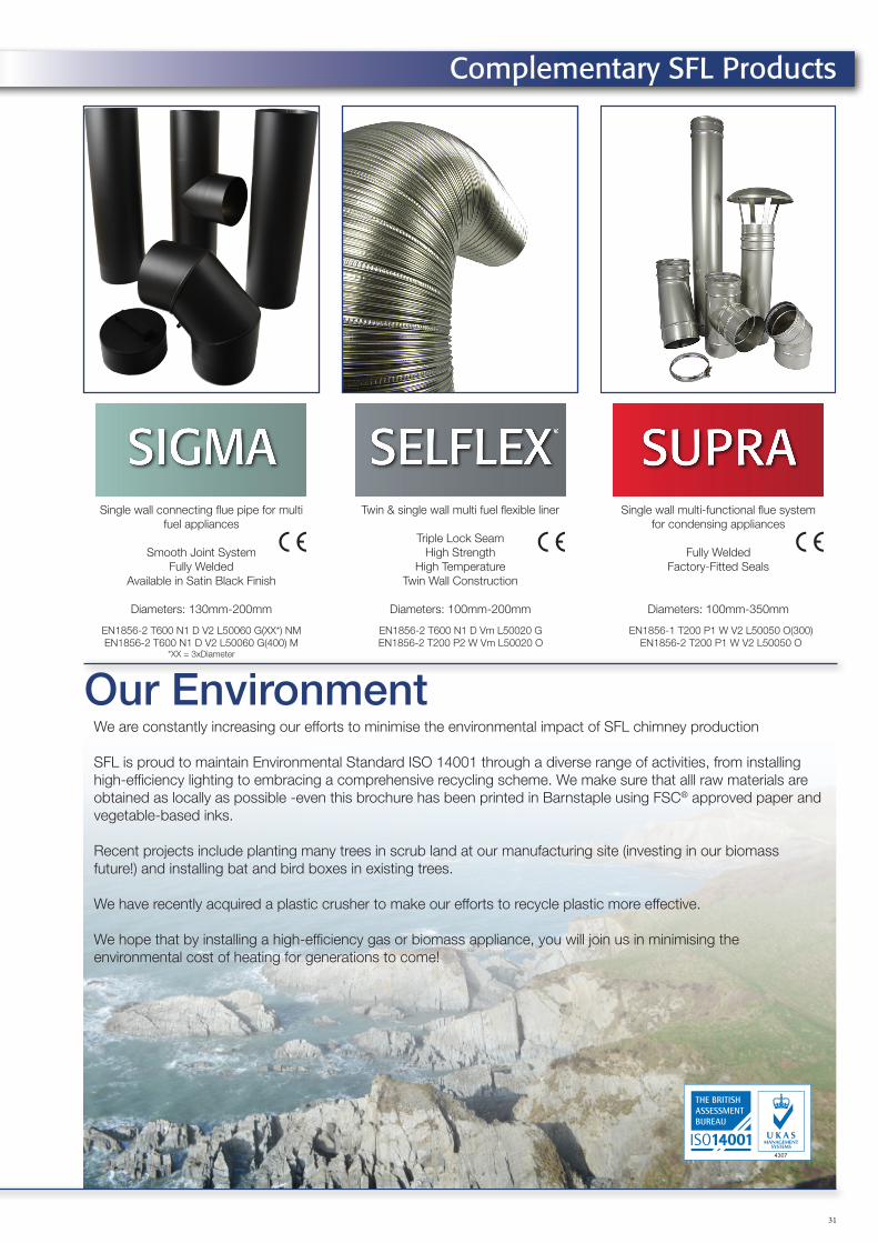
Complementary SFL Products
Single wall connecting flue pipe for multi fuel appliances
Smooth Joint SystemFully Welded
Available in Satin Black Finish
Diameters: 130mm-200mm
Twin & single wall multi fuel flexible liner
Triple Lock SeamHigh Strength
High TemperatureTwin Wall Construction
Diameters: 100mm-200mm
Single wall multi-functional flue system for condensing appliances
Fully WeldedFactory-Fitted Seals
Diameters: 100mm-350mm
Our EnvironmentWe are constantly increasing our efforts to minimise the environmental impact of SFL chimney production
SFL is proud to maintain Environmental Standard ISO 14001 through a diverse range of activities, from installing high-efficiency lighting to embracing a comprehensive recycling scheme. We make sure that alll raw materials are obtained as locally as possible -even this brochure has been printed in Barnstaple using FSC® approved paper and vegetable-based inks.
Recent projects include planting many trees in scrub land at our manufacturing site (investing in our biomass future!) and installing bat and bird boxes in existing trees.
We have recently acquired a plastic crusher to make our efforts to recycle plastic more effective.
We hope that by installing a high-efficiency gas or biomass appliance, you will join us in minimising the environmental cost of heating for generations to come!
EN1856-1 T200 P1 W V2 L50050 O(300)EN1856-2 T200 P1 W V2 L50050 O
EN1856-2 T600 N1 D Vm L50020 GEN1856-2 T200 P2 W Vm L50020 O
EN1856-2 T600 N1 D V2 L50060 G(XX*) NMEN1856-2 T600 N1 D V2 L50060 G(400) M
*XX = 3xDiameter
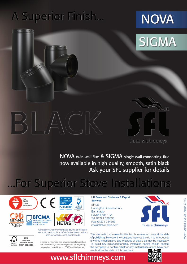
NOVA twin-wall flue & SIGMA single-wall connecting flue now available in high quality, smooth, satin black
Ask your SFL supplier for details
NOVA
SIGMA
A Superior Finish...
...For Superior Stove InstallationsUK Sales and Customer & Export Services
SF LtdPottington Business ParkBarnstapleDevon EX31 1LZTel: 01271 326633Fax: 01271 334303 [email protected]
In order to minimise the environmental impact on this publication, it has been printed locally, using vegetable based inks on FSC
® certified paper.
The information contained in this brochure was accurate at the date of publishing. However the company reserves the right to introduce at any time modifications and changes of details as may be necessary. To avoid any misunderstanding, interested parties should contact the company to confirm whether any material alterations have been made since the date of this brochure.
NO
VA®
Lite
ratu
re ©
SF
Ltd
- Ve
rsio
n 2
7101
6
www.sflchimneys.com
®
BLACK
Consider your environment and download the latest electronic version of the NOVA® sales literature direct
from our website using the QR code
Related Documents