IN THE UNITED STATES DISTRICT COURT FOR THE DISTRICT OF KANSAS THE UNITED STATES OF AMERICA, ) ) Plaintiff, ) ) v. ) Civ. No. 13-02141-JWL-KGG ) THE UNIFIED GOVERNMENT OF ) NOTICE OF CONCLUSION OF WYANDOTTE COUNTY AND THE ) DISPUTE RESOLUTION PROCESS CITY OF KANSAS CITY, KANSAS, ) AND FINAL INTEGRATED and THE STATE OF KANSAS, ) OVERFLOW CONTROL PROGRAM ) Defendants. ) ____________________________________) Plaintiff, the United States of America, on behalf of the United States Environmental Protection Agency (“EPA”), and Defendants the Unified Government of Wyandotte County and the City of Kansas City, Kansas (“Unified Government”) and the State of Kansas, hereby jointly notify the Court that the formal dispute resolution process initiated by the Unified Government regarding the Integrated Overflow Control Program (“IOCP”) approved with conditions by EPA, pursuant to the Partial Consent Decree (“Consent Decree”) entered in this action on May 20, 2013 (Dkt. No. 8), has concluded with agreement among the Parties. The Consent Decree requires the Unified Government to develop, and implement after EPA approval (or approval with conditions), the IOCP to ensure the Unified Government will achieve and maintain compliance with the Clean Water Act and its permits. Consent Decree, ¶¶ 46, 59, 71, & 72. EPA approved the Unified Government’s proposed IOCP on November 7, 2019 with specified conditions. On December 20, 2019 the Unified Government initiated the JOINT NOTICE OF CONCLUSION OF DISPUTE RESOLUTION PROCESS AND FINAL IOCP (Civ. No. 13-02141-JWL-KGG)- Page 1

Welcome message from author
This document is posted to help you gain knowledge. Please leave a comment to let me know what you think about it! Share it to your friends and learn new things together.
Transcript
IN THE UNITED STATES DISTRICT COURT FOR THE DISTRICT OF KANSAS
THE UNITED STATES OF AMERICA, ) )
Plaintiff, ) )
v. ) Civ. No. 13-02141-JWL-KGG )
THE UNIFIED GOVERNMENT OF ) NOTICE OF CONCLUSION OF WYANDOTTE COUNTY AND THE ) DISPUTE RESOLUTION PROCESS CITY OF KANSAS CITY, KANSAS, ) AND FINAL INTEGRATED and THE STATE OF KANSAS, ) OVERFLOW CONTROL PROGRAM
) Defendants. )
____________________________________)
Plaintiff, the United States of America, on behalf of the United States Environmental
Protection Agency (“EPA”), and Defendants the Unified Government of Wyandotte County and
the City of Kansas City, Kansas (“Unified Government”) and the State of Kansas, hereby jointly
notify the Court that the formal dispute resolution process initiated by the Unified Government
regarding the Integrated Overflow Control Program (“IOCP”) approved with conditions by EPA,
pursuant to the Partial Consent Decree (“Consent Decree”) entered in this action on May 20,
2013 (Dkt. No. 8), has concluded with agreement among the Parties.
The Consent Decree requires the Unified Government to develop, and implement after
EPA approval (or approval with conditions), the IOCP to ensure the Unified Government will
achieve and maintain compliance with the Clean Water Act and its permits. Consent Decree,
¶¶ 46, 59, 71, & 72. EPA approved the Unified Government’s proposed IOCP on November 7,
2019 with specified conditions. On December 20, 2019 the Unified Government initiated the
JOINT NOTICE OF CONCLUSION OF DISPUTE RESOLUTION PROCESS AND FINAL IOCP (Civ. No. 13-02141-JWL-KGG)- Page 1
formal dispute resolution process set forth under the Consent Decree regarding EPA’s decision.
Consent Decree, ¶ 90. Following the Parties’ exchange of Statements of Position, and additional
conferencing, EPA issued an amended and Final IOCP on March 23, 2020, and on April 30,
2020, the Unified Government agreed to implement (and not further dispute) the IOCP.
The March 23, 2020 Final IOCP, attached hereto as Appendix A, requires the Unified
Government to perform injunctive relief to improve its sewer and storm water systems and
address the violations alleged by the United States against the Unified Government in the March
21, 2013 Complaint (Dkt. No. 1). Pursuant to Paragraphs 59, 71, and 72 of the Consent Decree,
the IOCP, upon its approval by EPA, was incorporated into the Consent Decree, and the IOCP is
an enforceable part of the decree. No further action is required by this Court at this time. Per
Section XXI (Retention of Jurisdiction) of the Consent Decree, the Court retains jurisdiction over
the Consent Decree, including the IOCP, for purposes including effectuating or enforcing
compliance with its terms. Id. at ¶ 112.
The United States and the Unified Government will also soon file, and request this Court
enter, a Stipulation of Settlement to resolve the United States’ claims for civil penalties for the
violations alleged in the Complaint. Together the IOCP and the Stipulation of Settlement, once
entered, will provide relief to address all claims in the United States’ Complaint.
Date: May 5, 2020 Respectfully submitted,
For the United States: /s/ Erika M. Wells
ERIKA M. Wells Trial Attorney, Oregon Bar No. 055004 U.S. Department of Justice Environment and Natural Resources Division Environmental Enforcement Section c/o NOAA, Damage Assessment 7600 Sand Point Way, N.E.
JOINT NOTICE OF CONCLUSION OF DISPUTE RESOLUTION PROCESS AND FINAL IOCP (Civ. No. 13-02141-JWL-KGG)- Page 2
Seattle, Washington 98115 Telephone:(206) 526-6608 Facsimile: (206) 526-6665 [email protected]
OF COUNSEL:
PATRICIA GILLISPIE MILLER Senior Counsel, Kansas Bar No. 12096 United States Environmental Protection Agency Region 7 11201 Renner Road Lenexa, Kansas 66219 Telephone: (913) 551-7283 Facsimile: (913) 551-9283
For the Unified Government: /s/ Frank Paul Calamita, III____________ FRANK PAUL CALAMITA, III AquaLaw, PLC 6 South 5th Street Richmond, VA 23219 (804) 716-9021 x201 [email protected]
For the State of Kansas: /s/ Kate J. Gleeson __________________ Kate J. Gleeson, No. 25518 Kansas Dept. of Health and Environment 1000 SW Jackson, Suite 560 Topeka, Kansas 66612 [email protected] T: (785) 296-1607 F: (785) 559-4272
JOINT NOTICE OF CONCLUSION OF DISPUTE RESOLUTION PROCESS AND FINAL IOCP (Civ. No. 13-02141-JWL-KGG)- Page 3
CERTIFICATE OF SERVICE
I hereby certify that on May 5, 2020, I filed the foregoing,
NOTICE OF CONCLUSION OF DISPUTE RESOLUTION PROCESS AND FINAL INTEGRATED OVERFLOW CONTROL PROGRAM,
with the CM/ECF system, which caused a copy to be served on all counsel registered in this
matter, and also served a copy via e-mail to the counsel listed below:
Attorney for Defendant Unified Government of Wyandotte County and Kansas City, Kansas:
Frank Paul Calamita, III AquaLaw PLC 6 South 5th Street Richmond, Virginia 23219 (804) 716-9021 x201 [email protected]
Attorney for Defendant the State of Kansas:
Kate Gleeson Attorney Environmental Practice Group Kansas Department of Health and Environment 1000 SW Jackson, Suite 560 Topeka, KS 66612 (785) 296-1607 Email: [email protected]
/s Erika M. Wells Erika M. Wells Environmental Enforcement Section Environment and Natural Resources Division U.S. Department of Justice
JOINT NOTICE OF CONCLUSION OF DISPUTE RESOLUTION PROCESS AND FINAL IOCP (Civ. No. 13-02141-JWL-KGG)- Page 4
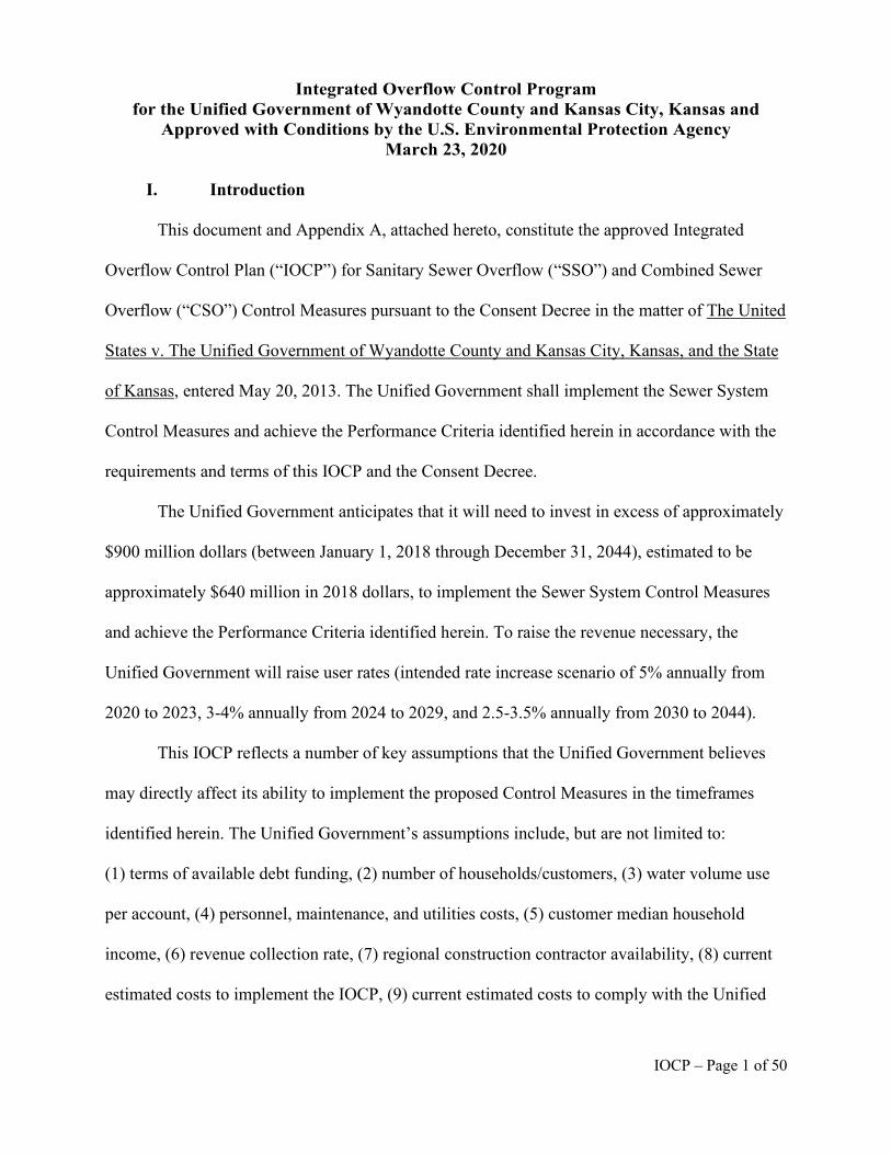
Integrated Overflow Control Program for the Unified Government of Wyandotte County and Kansas City, Kansas and
Approved with Conditions by the U.S. Environmental Protection Agency March 23, 2020
I. Introduction
This document and Appendix A, attached hereto, constitute the approved Integrated
Overflow Control Plan (“IOCP”) for Sanitary Sewer Overflow (“SSO”) and Combined Sewer
Overflow (“CSO”) Control Measures pursuant to the Consent Decree in the matter of The United
States v. The Unified Government of Wyandotte County and Kansas City, Kansas, and the State
of Kansas, entered May 20, 2013. The Unified Government shall implement the Sewer System
Control Measures and achieve the Performance Criteria identified herein in accordance with the
requirements and terms of this IOCP and the Consent Decree.
The Unified Government anticipates that it will need to invest in excess of approximately
$900 million dollars (between January 1, 2018 through December 31, 2044), estimated to be
approximately $640 million in 2018 dollars, to implement the Sewer System Control Measures
and achieve the Performance Criteria identified herein. To raise the revenue necessary, the
Unified Government will raise user rates (intended rate increase scenario of 5% annually from
2020 to 2023, 3-4% annually from 2024 to 2029, and 2.5-3.5% annually from 2030 to 2044).
This IOCP reflects a number of key assumptions that the Unified Government believes
may directly affect its ability to implement the proposed Control Measures in the timeframes
identified herein. The Unified Government’s assumptions include, but are not limited to:
(1) terms of available debt funding, (2) number of households/customers, (3) water volume use
per account, (4) personnel, maintenance, and utilities costs, (5) customer median household
income, (6) revenue collection rate, (7) regional construction contractor availability, (8) current
estimated costs to implement the IOCP, (9) current estimated costs to comply with the Unified
IOCP – Page 1 of 50
Government’s NPDES permits, and (10) other factors referenced in the 1997 Combined Sewer
Overflows – Guidance for Financial Capability Assessment and Schedule Development.
II. Definitions
All terms used in this IOCP shall have the meaning set forth in Section IV of the Consent
Decree (Definitions) and as supplemented or modified by the definitions set forth below:
“Achieve Full Operation” shall mean, as applicable, (a) the date by which construction in
accordance with the applicable Design Criteria has been completed for each Control Measure
identified in Tables 1.1 and 2.1 of this IOCP, and full operation of the Control Measure has been
commenced and verified or (b) the date by which construction has been completed for each
Infrastructure Project identified in Tables 3.2 and 3.3 in Section IV of this IOCP (Infrastructure
Projects) and the achievement of full operation of the Project has been verified.
“Adequate Capacity” shall mean the ability to collect, convey and treat peak wet weather
flows in the Separate Sewer System for a 5-year design storm event, except where indicated in
Table 1.2 of this IOCP for a 2-year design storm event. (This definition replaces the definition of
“Adequate Capacity” in the Consent Decree.)
“Capacity, Management, Operations, and Maintenance” or “CMOM” shall mean, the
Unified Government’s program for managing, operating, and maintaining its Sewer System,
which was approved by EPA on November 20, 2014, as it may be amended. (This definition
replaces the definition of “Capacity, Management, Operation, and Maintenance” in the Consent
Decree.)
“Combined Sewer System Interim Performance Benchmarks” or “CSS Interim
Performance Benchmarks” shall mean the cumulative level of system-wide wet weather CSO
volume reductions in the Design Year identified in Table 2.2 of this IOCP at the end of each
Achieve Full Operation period for the corresponding CSO Control Measures identified in
IOCP – Page 2 of 50
Table 2.1 of this IOCP. The CSS Interim Performance Benchmarks provide a point of reference
to monitor progress towards achievement of the CSS Performance Criteria such that appropriate
adjustments may be made as proposed in appropriate Supplemental Compliance Plans (as part of
Control Measures Reports). Stipulated penalties for failure to meet the CSS Interim Performance
Benchmarks shall accrue from the applicable deadlines in Table 2.2, unless the Unified
Government has timely submitted an adequate Supplemental Compliance Plan pursuant to
Section III.H of this IOCP.
“Combined Sewer System Performance Criteria” or “CSS Performance Criteria” shall
mean the level of control following the Unified Government’s achievement of full operation of
all the CSO Control Measures specified in Table 2.1 of this IOCP that achieves: (a) discharges
of no more than 4 to 6 times in the Design Year to Jersey Creek (CSOs 14, 15, 16, 17, 19, 55 and
81, or other CSOs, if approved by EPA); and (b) system-wide percent capture of Design Year
wet weather volume of no less than 85 percent.
“Construction Start Date” shall mean the date by which physical construction activities
will commence for each SSO or CSO Control Measure identified in Tables 1.1 and 2.1 in
Section III of this IOCP (CSO and SSO Control Measures) and for each Infrastructure Project
identified in Tables 3.2 and 3.3 in Section IV of this IOCP (Infrastructure Projects), which the
Unified Government may correlate to its “Notice to Proceed.”
“Control Measures” shall mean the remedial measures for the Sewer System identified in
this IOCP.
“Control Measures Report” shall mean a report periodically performed and submitted by
the Unified Government, pursuant to the requirements of Sections III (SSO and CSO Control
Measures) and V (Post-Construction Monitoring Program) of this IOCP, evaluating the
IOCP – Page 3 of 50
effectiveness of SSO and CSO Control Measures and any applicable Projects identified in
Section IV (Infrastructure Projects) of this IOCP.
“Design Year” shall mean the rainfall distribution patterns and recurrence intervals
developed to represent conditions expected in a typical or “average” year applied to hydraulic
models when modeling existing conditions and alternative control scenarios for the CSS. Design
storms are utilized to mimic the event distribution on an annual and seasonal basis resulting in a
full Design Year hyetograph. For purposes of the Consent Decree, the Design Year is defined as
the design storms which have the depth, peak hourly intensity, duration, and frequency as
described in Section 3.3 of the Draft CSS Characterization Report submitted by the Unified
Government on May 31, 2015, and restated in Section VII of this IOCP. (This definition replaces
the definition of “Design Year” in the Consent Decree.)
“Dry Weather” shall mean a twenty-four (24) hour period with no more than one-tenth of
an inch of rainfall, preceding a combined sewer overflow event.
“Infrastructure Projects” or “Projects” shall mean the annually recurring and remedial
Work in the Sewer System and Municipal Separate Storm Sewer System (“MS4”) identified in
Section IV of this IOCP.
“Integrated Overflow Control Plan” or “IOCP” shall mean this IOCP and any revisions to
this IOCP that have been approved by EPA, after consultation with the State.
“MS4 Permit” shall mean NPDES Permit No. KS0095656 (“MS4 Permit”), with an
effective date of February 1, 2020, and any subsequently issued permit, which authorizes
discharges from the Unified Government’s MS4 in accordance with conditions specified therein.
(This definition replaces the definition of “MS4 Permit” in the Consent Decree.)
IOCP – Page 4 of 50
“Performance Criteria” shall mean the numeric and narrative specifications included in
Section III of this IOCP that must be met following the Unified Government’s achievement of
full operation of the Control Measures specified in Section III.
“Private Lateral” shall mean that portion of the Sewer System not owned by the Unified
Government used to convey wastewater from a building or buildings to that portion of the Sewer
System owned by the Unified Government. A Private Lateral includes the connection to the
Unified Government’s sewer line. (This definition replaces the definition of “Private Lateral” in
the Consent Decree.)
“Private Property Backup” shall mean any release of wastewater from the Unified
Government’s Sewer System into buildings or onto private property that occurs when a
wastewater backup occurs into a building and is caused by blockages, flow conditions, or other
conditions in the Sewer System. For purposes of the Consent Decree a wastewater backup that is
caused solely by conditions in a Private Lateral or privately-owned sewer is not a Private
Property Backup or SSO. (This definition replaces the definition of “Private Property Backup” in
the Consent Decree.)
“Project Start Date” shall mean the Calendar Year during which design and other work
related to a Control Measure listed in Tables 1.1 or 2.1, or an Infrastructure Project listed in
Tables 3.2 or 3.3, is expected to commence.
“Sanitary Sewer System Performance Criteria” or “SSS Performance Criteria” shall mean
the numeric and narrative specifications included in Section III of this IOCP, Table 1.2, that
must be met following the Unified Government’s achievement of full operation of the SSO
Control Measures specified in Section III of this IOCP, Table 1.1.
“Supplemental Compliance Plan” or “SCP” shall mean a proposed plan, submitted by the
Unified Government in accordance with Section III of this IOCP, for additional Control
IOCP – Page 5 of 50
Measure(s) to address a failure of Control Measure(s) identified in Section III to meet the CSS
Interim Performance Benchmarks or SSS Performance Criteria by the applicable Achieve Full
Operation date. The Control Measure(s), design criteria and schedule(s) approved by the
Environmental Protection Agency (“EPA”) in a Supplemental Compliance Plan (“SCP”) are
incorporated into and enforceable under the Decree.
III. CSO and SSO Control Measures
A. Implementation
1. The Unified Government shall implement the Control Measures for the Sewer
System in accordance with Section III (Objectives) of the Consent Decree and with the
Performance Criteria and by the deadlines to Achieve Full Operation set forth in this IOCP. All
Control Measures shall be completed and in full operation by no later than December 31, 2044.
2. Additional Jersey Creek CSO Control Measures. By no later than December 31,
2020, the Unified Government shall submit to EPA for review and approval in accordance with
Section XII (Reporting, Certification and Approval of Submittals) of the Consent Decree,
proposed CSO Control Measure(s) to reduce overflows at CSOs 14, 15, 16, 17, 19, 55 and 81 to
no more than four to six overflows in the Design Year. The proposed CSO Control Measure(s)
submittal shall include a schedule for achievement of full operation of such measures as
expeditiously as possible, but no later than December 31, 2032. As part of its proposed plan, the
Unified Government may propose adjustments, as appropriate, to the CSO Control Measures,
Design Criteria, Project Start dates, and Achieve Full Operation dates for the existing CSO
Control Measures identified in Table 2.1, and Post-Construction Monitoring Program, to offset
the increased percent capture that will be achieved because of the additional treatment
requirements in this paragraph for the CSOs discharging into Jersey Creek from the percent
capture that will be achieved from any remaining CSO Control Measures. Any such adjustments
IOCP – Page 6 of 50
shall still ensure the achievement of the system-wide percent capture of Design Year wet weather
volume of no less than 85 percent. Any such proposed adjustments are subject to EPA review
and approval. Proposed adjustments under this Paragraph may be made under Section III.D
(Adaptive Management) of the IOCP, if such adjustments meet the criteria set forth in that
Section, or Section XXII (Modification) of the Consent Decree. The Unified Government may
also propose, with justification, alternative CSOs in Jersey Creek to the CSOs listed above for
additional control. Such a proposal for changing the CSOs to be addressed shall, at a minimum,
provide an updated CSO prioritization review and demonstrate that the proposed CSO Control
Measure(s) will achieve an equivalent or better reduction in overflow volume and activation
frequency for the segment of Jersey Creek located in Jersey Creek Park (south of Parallel
Parkway between approximately North 5th Street and North 18th Street). EPA’s disapproval of
the Unified Government’s proposal to change the CSOs to be addressed in Jersey Creek shall not
be subject to Dispute Resolution.
3. Post-Construction Monitoring. The Unified Government shall immediately
implement the Post-Construction Monitoring Program in Section V of this IOCP.
4. Achievement of Compliance. The Unified Government shall ensure that all
Control Measures are designed and implemented in accordance with sound engineering practices
to ensure Performance Criteria will be achieved and the Objectives set forth in Section III of the
Consent Decree are satisfied. The Unified Government shall Achieve Full Operation for the
Control Measures set forth in this IOCP by the specified dates, but in no event later than
December 31, 2044. After achievement of full operation for all Control Measures, and in no
event later than December 31, 2046, the Unified Government shall complete Post-Construction
Monitoring and submit the final Post-Construction Monitoring Report in accordance with
Section V, below.
IOCP – Page 7 of 50
B. Sanitary Sewer Overflow Controls
5. In accordance with Section XI (Implementation of the IOCP) of the Consent
Decree, the Unified Government shall implement the SSO Control Measures in accordance with
the schedules set forth in Table 1.1, below, and shall achieve the Sanitary Sewer System (“SSS”)
Performance Criteria storm event levels of service set forth in Table 1.2.
6. Each Annual Report required by Paragraph 60 of the Consent Decree shall
include updated project information, including anticipated and actual Construction Start Date and
Achieve Full Operation dates, and project status updates for each SSO Control Measure.
C. Combined Sewer Overflow Controls
7. In accordance with Section XI of the Consent Decree (Implementation of the
IOCP), the Unified Government shall implement the CSO Control Measures in accordance with
the schedules set forth in Table 2.1, below, and shall achieve the following Performance Criteria
for the Combined Sewer System (“CSS”):
a. By no later than December 31, 2032, the CSOs that discharge to Jersey Creek
(CSOs 14, 15, 16, 17, 19, 55 and 81, or other CSOs, if approved by EPA) shall
discharge no more than 4 to 6 times in the Design Year; and
b. By no later than December 31, 2044, the system-wide Design Year wet weather
CSO discharge volume remaining upon completion of the CSO Control Measures
shall be no more than 378 million gallons (“MG”), which the Unified
Government represents as 85 percent wet weather capture within the CSS.
i. The Unified Government represents that the current CSO discharge
volume as of the Date of submittal of the Unified Government’s Draft
IOCP Supplement, August 31, 2018, is 845 MG. The baseline of 845 MG
IOCP – Page 8 of 50
CSO discharge volume will be used to measure compliance with the CSS
Interim Performance Benchmarks and Performance Criteria.
8. Each Annual Report required by Paragraph 60 of the Consent Decree shall
include updated project information, including anticipated and actual Construction Start Date and
Achieve Full Operation dates, and project status updates for each CSO Control Measure.
D. Adaptive Management for SSO and CSO Control Measures
9. At least ninety (90) days prior to the Construction Start Date for each SSO or
CSO Control Measure (Tables 1.1 and 2.1), the Unified Government may submit a proposal to
EPA, for review and approval, of one or more deleted, revised and/or alternative Control
Measure(s), including Design Criteria and Achieve Full Operation dates, in lieu of the specific
SSO and CSO Control Measures set forth in Tables 1.1 (SSO Control Measures) and 2.1 (CSO
Control Measures), respectively. The Unified Government will provide additional advance time
for EPA review of more complex proposals, as appropriate. Each proposal for a deleted, revised
and/or alternative Control Measure(s) shall:
a. Provide detailed project information and Design Criteria (such as size and length
of new sewer lines, sewer infrastructure or upgraded pumping capacity; the
volume of storage, acreage of Green Infrastructure improvements, or acreage of
CSS area to be separated; and the anticipated volume reduction or level of service,
etc.);
b. Include an implementation schedule for completion of revised and/or alternative
Control Measures by the same Achieve Full Operation date as the original Control
Measures set forth in Tables 1.1 and 2.1, notwithstanding, the Unified
Government may request, and EPA may approve, an extension of the Achieve
IOCP – Page 9 of 50
Full Operation date of up to one year where the Unified Government
demonstrates the need for such an extension; and
c. Demonstrate that any deleted, revised and/or alternative Control Measures that
vary from the Design Criteria in Tables 1.1 or 2.1 will achieve equal to or better
SSO Level of Service, CSS Interim Performance Benchmarks or, where
applicable, CSS Performance Criteria than what would be achieved by the
original Control Measure(s).
10. EPA disapproval of a proposal for deleted, revised and/or alternative SSO or CSO
Control Measures is subject to Section XV (Dispute Resolution) of the Consent Decree under the
standard of review set forth in Paragraph 94(a) (Disputes Concerning Matters Accorded Record
Review). For purposes of the Consent Decree, EPA approval of a proposed deleted, revised and/or
alternative Control Measure that meets the requirements of Paragraph 9 and does not change the
final deadline for compliance under this IOCP (Paragraph 1), the CSS Interim Performance
Benchmarks (Table 2.2, below) or the SSS or CSS Performance Criteria, and does not extend the
Achieve Full Operation date (Tables 1.1 and 2.1) by more than one year, shall not be considered
a Modification pursuant to Section XXII of the Consent Decree.
E. Modification Based on Changed Financial Circumstances
11. It is recognized that the information currently available to the Unified
Government as well as the Unified Government’s current assumptions and projections may
change during implementation of the Control Measures. The Unified Government may submit a
proposal to EPA to modify the schedule and/or the Control Measures set forth in Tables 1.1
(SSO Control Measures) and 2.1 (CSO Control Measures), respectively, pursuant to Section
XXII (Modification) of the Consent Decree, based on a significant adverse change in the
information currently available to the Unified Government, the Unified Government’s current
IOCP – Page 10 of 50
assumptions or projections, its financial circumstances or other financial or budgetary issues,
whether or not such change is anticipated.
12. In the event that the Unified Government seeks to modify the schedule and/or the
Control Measures set forth in Tables 1.1 (SSO Control Measures) and 2.1 (CSO Control
Measures), respectively, based upon a significant increase in costs or other changes in financial
circumstances, the Unified Government shall submit to EPA a current Financial Capability
Assessment (based on EPA’s Combined Sewer Overflows—Guidance for Financial Capability
Assessment and Schedule Development, referenced at EPA 832-B-97-004 and dated February of
1997, and EPA’s Financial Capability Assessment Framework, dated November 24, 2014, or
subsequent versions thereof). The Unified Government may also submit with its request any
other information that the Unified Government would like EPA to consider regarding the
requested modification.
F. SSS Performance Criteria Evaluations
13. The Unified Government shall perform and submit to the EPA, for review and
approval pursuant to Section XII of the Consent Decree (Reporting, Certification and Approval
of Submittals), a Control Measures Report with its Annual Report for the Calendar Year
following the Achieve Full Operation deadline for each SSO Control Measure identified in
Table 1.1 that demonstrates that the applicable SSS Performance Criteria Level of Service
specified in Table 1.2 has been achieved. For each submittal, the Unified Government shall
comply with the requirements for Control Measures Reports specified in Section V of this IOCP
(Post-Construction Monitoring Program) and run a design storm simulation of the most recently
calibrated hydraulic model to demonstrate achievement of the Level of Service identified in
Table 1.2 for each SSO Control Measure.
IOCP – Page 11 of 50
G. CSS Interim Performance Benchmark Evaluations
14. The Unified Government shall perform and submit to the EPA, for review and
approval pursuant to Section XII of the Consent Decree (Reporting, Certification and Approval
of Submittals), a Control Measures Report with its Annual Report for the Calendar Year
following the Achieve Full Operation deadline for the CSO Control Measures identified in
Table 2.1 within each CSS Interim Performance Benchmark period identified in Table 2.2 that
demonstrates that the applicable Interim Performance Benchmark has been achieved. For each
evaluation, the Unified Government shall comply with the requirements for Control Measures
Reports specified in Section V (Post-Construction Monitoring Program), below, and:
a. run a continuous simulation of the most recently calibrated hydraulic model using
the Design Year to demonstrate progress toward achievement of the CSS
Performance Criteria and the CSS Interim Performance Benchmarks identified in
Table 2.2; and
b. analyze whether Control Measures will ultimately achieve the CSS Performance
Criteria and, when applicable, the next cumulative CSS Interim Performance
Benchmark.
H. Supplemental Compliance Plans
15. If, following post-construction monitoring as required by Section V (Post-
Construction Monitoring Program), below, the analysis indicates that any SSO Control Measure
identified in Table 1.1 fails to achieve the Level of Service identified in Table 1.2 or that a CSS
Interim Performance Benchmark in Table 2.2 will not be achieved by the date specified, the
Unified Government shall submit to EPA, for review and approval, a Supplemental Compliance
Plan (“SCP”) by no later than August 31 following submittal of the Control Measures Report for
IOCP – Page 12 of 50
that SSO Control Measure pursuant to Paragraph 13 or CSS Interim Performance Benchmark
pursuant to Paragraph 14, as applicable. At a minimum, the SCP shall include:
a. a detailed description of the proposed and/or revised control measure(s) to be
implemented to address the shortcomings;
b. a demonstration that implementation of the proposed SCP will, as appropriate,
(i) achieve an equal to or better SSO Level of Service than that which was
required for the original Control Measure or (ii) achieve equal to or better CSS
Interim Performance Benchmarks and CSS Performance Criteria than that which
was applicable to the original Control Measure;
c. a schedule for implementation of the control measure(s) that is as expeditious as
possible, but no later than 2 years after EPA approval of the SCP, unless EPA
approves a later date; and
d. a post-construction monitoring plan for the proposed work in accordance with
Section V (Post-Construction Monitoring Program), below.
16. The deadline to Achieve Full Operation for a SCP approved by EPA under this
procedure to address a failed SSO Control Measure or missed CSS Interim Performance
Benchmark shall be incorporated into Table 1.1 or Table 2.1, as applicable, as the date to
Achieve Full Operation under this IOCP.
17. EPA disapproval of a proposed SCP is subject to Section XV (Dispute
Resolution), under the standard of review set forth in Paragraph 94(a) (Disputes Concerning
Matters Accorded Record Review). For purposes of the Consent Decree, EPA’s approval of a
SCP that does not change the final deadline for compliance in Paragraph 1, above, the CSS
Interim Performance Benchmarks or the SSS or CSS Performance Criteria shall not be
considered a Modification pursuant to Section XXII of the Decree.
IOCP – Page 13 of 50
I. Demonstration of Compliance
18. SSOs. Upon completion of the SSO Control Measures identified in Table 1.1,
below, the Unified Government shall use the validated and/or recalibrated SSS hydraulic models
to run the 2-year and 5-year design storm events to demonstrate compliance with SSO
elimination, in accordance with Section III of the Consent Decree (Objectives). The Unified
Government shall characterize any rain events that triggered SSOs and demonstrate, consistent
with the Post-Construction Monitoring Program as required by Section V of the IOCP, that the
SSS has Adequate Capacity.
19. Such a demonstration shall be made using the validated and/or recalibrated Sewer
System hydraulic models consistent with the models the Unified Government used to develop
the proposed IOCP submitted by the Unified Government in September 2016, pertinent parts of
which are summarized in Subsection J, below. The models used were dynamic hydraulic system
models that were developed, calibrated and verified based on sewer system flow and rainfall
data. The Sewer System hydraulic models are described in Section 2.2 of the Unified
Government’s September 2016 proposed IOCP.
20. CSOs. Upon completion of the CSO Control Measures identified in Table 2.1,
below, the Unified Government shall demonstrate compliance with the CSS Performance
Criteria as set forth herein. Achievement of the CSS Performance Criteria shall be completed in
compliance with the Post-Construction Monitoring Program identified in Section V of this
IOCP using the latest version of its Sewer System hydraulic model as described in Subsection J
and the latest Sewer System monitoring data from the Post-Construction Monitoring Program,
as completed in accordance with Section V of this IOCP.
21. The Unified Government shall calibrate the Sewer System hydraulic model in
accordance with current industry calibration standards. Upon calibration of the Sewer System
IOCP – Page 14 of 50
hydraulic model (hereafter referred to as the “calibrated post-construction hydraulic model”), the
Unified Government shall run a continuous simulation of the model inputting the Design Year
used to develop the September 2016 proposed IOCP in place of the actual storms experienced
during the post-construction monitoring period.
22. The CSS Performance Criteria will be met if the continuous typical Design Year
simulation using the calibrated post-construction hydraulic model demonstrates the Sewer
System discharges will achieve the system-wide Design Year wet weather volume capture as
well as the Overflow Frequency (for Jersey Creek CSOs addressed by Paragraph 2, above only)
identified herein.
J. Summary of Hydraulic Model Information
23. CSS and SSS hydraulic model details are provided in Section 2 of the Unified
Government’s September 2016 proposed IOCP.
24. SSS Hydraulic Modeling. Similar to the CSS hydraulic modeling, the principal
tool used in assessing the capacity of the SSS was a dynamic hydraulic system model that was
developed, calibrated and verified on the basis of sewer system flow and rainfall data obtained
from a monitoring system specifically established and operated for that purpose. Innovyze’s
InfoWorks ICM was used for modeling the sewer system. The sewer system model couples base
flow, precipitation, subcatchment information, and conveyance system information with
hydrologic and hydraulic calculating procedures to simulate sewer system flow characteristics.
This tool supports the engineering analysis necessary to plan sewer system improvements.
IOCP – Page 15 of 50
Table 1.1 – SSO Control Measures1
SSO Control Measure Name Design Criteria2 Expected Benefits of Control
Measure Implementation Project
Start Date
Achieve Full Operation by
December 31 of stated year
Lower Connor Creek Interceptor
Install 16,000 LF of 36” diameter gravity interceptor to reroute former Pump Station 50 flow to the new Wolcott WWTP
Increases capacity for service population growth Reduces average daily flow and peak wet weather flows to Pump Station 6 and WWTP 20 Replaces aging pump station and force main infrastructure
2018 2022
Little Turkey Tributary North Interceptor Capacity Improvements
Replace existing gravity sewer with or build parallel relief gravity sewer of 150 LF of 24” diameter gravity sewer
Reduces surcharge potential Replaces aging pipe infrastructure
2020 2022
Wolcott WWTP, Phase 1 Construct new Wolcott WWTP with 2 MGD avg. daily flow (6 MGD peak wet weather flow)
Reduces O&M requirements Provides additional treatment capacity for growth and development Extends capacity of WWTP 20 Reduces nutrient loading to the Kansas River Improves Connor Creek water quality Replaces aging WWTP infrastructure Reduces average daily flow and peak wet weather flow to Pump Station 6 and Plant 20
2018 2022
1 The objective of the work in this Table 1.1 is to eliminate SSOs throughout Unified Government’s SSS. 2 The Design Criteria are based upon Long-Term Control Plan-level planning estimates and may be subject to revision during facility planning and design. The Control Measures will be designed in accordance with good engineering practice to ensure that the basin-wide Performance Criteria will be achieved. 3 Achieve Full Operation date is anticipated to be 2032 based on planning level flow projections of additional future growth within the service area. The Unified Government will provide information in the 2026 (or earlier) Annual Report demonstrating whether flows within the service area have approached the point where these projects are necessary and whether the Achieve Full Operation date should be modified accordingly.
IOCP – Page 16 of 50
SSO Control Measure Name Design Criteria2 Expected Benefits of Control
Measure Implementation Project
Start Date
Achieve Full Operation by
December 31 of stated year
Gravity Interceptor from Pump Station 45 to Pump Station 7
Install 3,000 LF of 36” diameter gravity sewer from Pump Station 45 to Pump Station 7 to alleviate surcharging upstream of Pump Station 45
Reduces surcharge potential Reduces O&M requirements Increases pipe capacity for service population growth
2026 2027
Pump Station 50 Elimination
Decommission Pump Station 50 Reduces O&M requirements 2027 20323
Wolcott WWTP Excess Flow Holding Basin
Construct 4 MG excess flow holding basin
Stores excess wet weather flows Reduces surcharge potential Reduces peak flows to Wolcott WWTP
2027 20323
Mill Creek Basin Capacity Improvements
Replace existing gravity sewer with, or build parallel relief gravity sewer of, 10,000 LF of 15” – 60” diameter gravity sewer
Reduces surcharge potential Replaces aging pipe infrastructure
2031 2032
Pump Station 40 Capacity Improvements
Replace pump station infrastructure to increase firm capacity to 1,100 gpm
Reduces surcharge potential Reduces potential for pump station asset damage Replaces aging infrastructure Increases system reliability Increases capacity for service population growth
2031 2032
IOCP – Page 17 of 50
SSO Control Measure Name Design Criteria2 Expected Benefits of Control
Measure Implementation Project
Start Date
Achieve Full Operation by
December 31 of stated year
Pump Stations 23, 24, 29, and 62 Capacity Improvements
Replace Pump Station 23 infrastructure and increase firm capacity from 100 gpm to 300 gpm Replace Pump Station 24 infrastructure to increase firm capacity from 329 gpm to 1,025 gpm Replace Pump Station 29 infrastructure to increase firm capacity from 100 gpm to 280 gpm Replace Pump Station 62 infrastructure to increase firm capacity from 168 gpm to 740 gpm
Reduces surcharge potential Increases capacity for service population growth
2031 2032
WWTP 20 Treatment Capacity Upgrade
Expand WWTP 20 to increase primary and secondary treatment capacity from 14 to 21 MGD avg. daily flow Install additional final clarifier, aerobic digester and aerobic sludge-holding basin
Reduces surcharge potential Reduces O&M requirements Increases capacity for service population growth Replaces aging infrastructure
2028 20323
Wolcott WWTP, Phase 2 Increase treatment capacity from 2 to 4 MGD avg. daily flow
Provides additional capacity for service population growth
2027 20323
IOCP – Page 18 of 50
SSO Control Measure Name Design Criteria2 Expected Benefits of Control
Measure Implementation Project
Start Date
Achieve Full Operation by
December 31 of stated year
Basin Capacity Improvements for: Brenner Heights Creek, Brenner Heights Tributary, Turner Creek, and Turkey Creek
Construct gravity sewer capacity improvements listed below to replace aging pipe infrastructure: Brenner Heights Creek – 8,000 LF of 8” to 15” diameter Brenner Heights Tributary – 1,000 LF of 8” to 12” diameter Turner Creek – 1,000 LF of 8” diameter Turkey Creek – 200 LF of 15” diameter
Reduces surcharge potential 2031 2037
Pump Station 6 Storage Construct new 0.6 MG excess flow holding basin
Reduces surcharge potential Increases capacity for service population growth
2034 2037
Pump Station 57 Force Main Capacity Improvements
Replace existing force main with installation of 2,000 LF of 6” diameter Force Main
Reduces surcharge potential Increases capacity for service population growth Replaces aging infrastructure
2033 2037
Pump Station 7 Storage Construct a new 0.6 MG excess flow holding basin
Reduces surcharge potential Increases capacity for service population growth
2035 2037
IOCP – Page 19 of 50
SSO Control Measure Name Design Criteria2 Expected Benefits of Control
Measure Implementation Project
Start Date
Achieve Full Operation by
December 31 of stated year
Pump Stations 25, 26, 27 Replace Pump Station 25 Reduces surcharge potential 2036 2037 and 55 Capacity infrastructure to increase firm Reduces potential for pump station Improvements capacity from 103 gpm to 300
gpm Replace Pump Station 26 infrastructure to increase firm capacity from 120 gpm to 520 gpm Replace Pump Station 27 infrastructure to increase firm capacity from 200 gpm to 340 gpm Replace Pump Station 55 infrastructure to increase firm capacity from 150 gpm to 208 gpm
asset damage Increases system reliability Increases capacity for service population growth Replaces aging infrastructure
IOCP – Page 20 of 50
Table 1.2 – SSS Performance Criteria
2-Year Storm Event Level of Service 5-Year Storm Event Level of Service
SSS Basin Emergency Relief Structure Number SSS Basin Emergency Relief
Structure Number Little Turkey
Tributary North East Mission Creek
Little Turkey Tributary South
331-008-MH Grinter Creek
Mill Creek 292-003-PS Little Turkey Creek North
Eddy Creek 133-040-MH 132-012-MH 141-015-MH
Little Turkey Creek South
Brenner Heights Creek
203-026-MH 204-026-MH 214-057-MH
Marshall Creek 320-023-MH 320-009-PS
Brenner Heights Tributary
Wolf Creek
Muncie Creek 199-014-MH Connor Creek 415-002-PS
Little Muncie Honey Creek
Turner Creek 185-033-PS Island Creek 504-002-PS
Turkey Creek Island Creek Tributary
Brush Creek 020-101-MH 020-121-MH
Piper Creek
Morris Creek
Indian Creek 145-014-PS
Santa Fe Bluff
Union Pacific Bottoms
Barber Creek 196-075-MH 196-120-MH
IOCP – Page 21 of 50
Table 2.1 – CSO Control Measures
CSO Control Measure Name
CSO(s) Addressed by Control Measure Design Criteria* Project
Start Date
Achieve Full Operation by
December 31 of stated year
CSO 19 Overflow Reduction
CSOs 19, 86 and 54 Localized sewer separation and green infrastructure to store up to 1.4” rainfall event
2018 2022, unless modified by an approved Jersey
Creek CSO Control Measures Plan
Armourdale Phase 1 Sewer Separation (14th and Osage)
CSOs 41, 42, 43, 44 and 48 Construct 2,000 LF 12” through 30” storm sewer and 1,000 LF 8” through 15” sanitary sewer
2023 2027
Armourdale Phase 2 Sewer Separation (Central Armourdale)
CSOs 43, 44, 48 and 66 Install approximately 2,000 LF 12” through 24” storm sewer and 9,000 LF 8” through 24” sanitary sewer
2024 2027
Argentine to Armourdale Siphon Restoration (Junction Box and Gates)
CSO 48 Structural modification to accommodate new 20” sluice gate in each gatewell structure
2024 2027
CSO Control Measures Report with Annual Report due February 28, 2029 Jersey Creek CSO Control Measure(s)**
CSOs 14, 15, 16, 17, 19, 55 and 81
TBD based on approved CSO Control Measures Plan (to be submitted by 12/31/2020)
TBD TBD, but no later than 2032
CSO 47 Overflow Reduction
CSOs 47, 48, 43 and 44 Construct 4,000 LF 12” through 30” storm sewer and 500 LF 8” through 15” sanitary sewer
2028 2032
CSO 54 and CSO 86 Structural Improvements
CSOs 54 and 86 Raise CSO 54 weir 4 feet; raise CSO 86 weir 2 feet; and upsize pipe from CSO 54 diversion structure to FID PS to 60” diameter
2028 2032
CSO Control Measures Report with Annual Report due February 28, 2034 CSO 55 Overflow Reduction
CSOs 55, 19, 86 and 54 Sewer separation and green infrastructure to provide wet weather storage for 1.4” rainfall event
2034 2037
IOCP – Page 22 of 50
CSO Control Measure Name
CSO(s) Addressed by Control Measure Design Criteria* Project
Start Date
Achieve Full Operation by
December 31 of stated year
FID Pump Station Downstream Sewer Capacity Improvements
CSOs 54 and 86 Increase capacity to FID PS to 30 MGD, rehabilitate existing 36” force main and construct parallel 30” force main
2033 2037
CSO Control Measures Report with Annual Report due February 28, 2039 Esplanade Basin Overflow Reduction (Green Infrastructure/Sewer Separation)
CSOs 27, 28, 29, 30, 31, 56 and 54
Construct 19,000 LF 12” through 48” storm sewer and 17,000 LF 8” through 24” sanitary sewer
2038 2044
AID Pump Station Downstream Sewer Capacity Improvements
CSOs 43, 44, 48 and 39 Construct new parallel force main (24” dry weather, 42” wet weather) from AID PS under the Kansas River to the Kaw Point WWTP
2038 2044
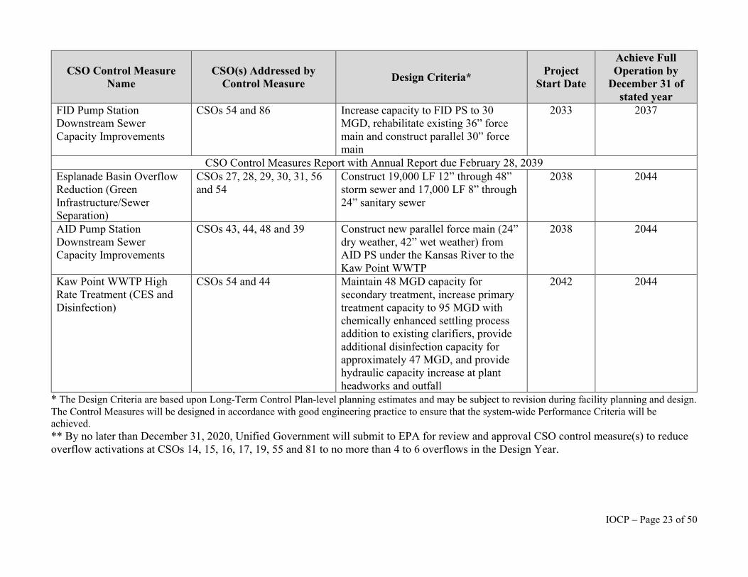
Kaw Point WWTP High Rate Treatment (CES and Disinfection)
CSOs 54 and 44 Maintain 48 MGD capacity for secondary treatment, increase primary treatment capacity to 95 MGD with chemically enhanced settling process addition to existing clarifiers, provide additional disinfection capacity for approximately 47 MGD, and provide hydraulic capacity increase at plant headworks and outfall
2042 2044
* The Design Criteria are based upon Long-Term Control Plan-level planning estimates and may be subject to revision during facility planning and design. The Control Measures will be designed in accordance with good engineering practice to ensure that the system-wide Performance Criteria will be achieved. ** By no later than December 31, 2020, Unified Government will submit to EPA for review and approval CSO control measure(s) to reduce overflow activations at CSOs 14, 15, 16, 17, 19, 55 and 81 to no more than 4 to 6 overflows in the Design Year.
IOCP – Page 23 of 50
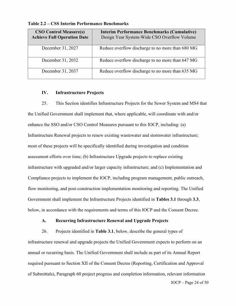
Table 2.2 – CSS Interim Performance Benchmarks
CSO Control Measure(s) Achieve Full Operation Date
Interim Performance Benchmarks (Cumulative) Design Year System-Wide CSO Overflow Volume
December 31, 2027 Reduce overflow discharge to no more than 680 MG
December 31, 2032 Reduce overflow discharge to no more than 647 MG
December 31, 2037 Reduce overflow discharge to no more than 635 MG
IV. Infrastructure Projects
25. This Section identifies Infrastructure Projects for the Sewer System and MS4 that
the Unified Government shall implement that, where applicable, will coordinate with and/or
enhance the SSO and/or CSO Control Measures pursuant to this IOCP, including: (a)
Infrastructure Renewal projects to renew existing wastewater and stormwater infrastructure;
most of these projects will be specifically identified during investigation and condition
assessment efforts over time; (b) Infrastructure Upgrade projects to replace existing
infrastructure with upgraded and/or larger capacity infrastructure; and (c) Implementation and
Compliance projects to implement the IOCP, including program management, public outreach,
flow monitoring, and post-construction implementation monitoring and reporting. The Unified
Government shall implement the Infrastructure Projects identified in Tables 3.1 through 3.3,
below, in accordance with the requirements and terms of this IOCP and the Consent Decree.
A. Recurring Infrastructure Renewal and Upgrade Projects
26. Projects identified in Table 3.1, below, describe the general types of
infrastructure renewal and upgrade projects the Unified Government expects to perform on an
annual or recurring basis. The Unified Government shall include as part of its Annual Report
required pursuant to Section XII of the Consent Decree (Reporting, Certification and Approval
of Submittals), Paragraph 60 project progress and completion information, relevant information
IOCP – Page 24 of 50
describing the nature and general scope of the expected work for Infrastructure Projects
identified in Table 3.1, below, that will be implemented in the next reporting period, and any
proposed changes to the schedule or scope of work for the Infrastructure Projects.
B. Specific Infrastructure Sewer System Renewal and Upgrade Projects
27. The Unified Government shall complete the scheduled specific infrastructure
renewal and upgrade Projects identified in Tables 3.2 and 3.3, below, according to the schedule
stated therein.
28. The Unified Government shall provide to EPA, for review and comment, any
proposed changes to the schedule or scope of work for the Infrastructure Projects identified in
Tables 3.2 and 3.3. Such proposed changes shall be included in the Annual Report required
pursuant to Section XII of the Consent Decree (Reporting, Certification and Approval of
Submittals), Paragraph 60, when possible, and submitted no later than ninety (90) days prior to
the Unified Government’s Construction Start Date for each such Project.
29. In the Annual Report required by Section XII of the Consent Decree (Reporting,
Certification and Approval of Submittals), the Unified Government shall provide project
progress and completion information for the Projects identified in Tables 3.2 and 3.3.
30. If requested, the Unified Government shall meet with the EPA on an annual basis
to review the overall progress made towards achieving program implementation.
IOCP – Page 25 of 50
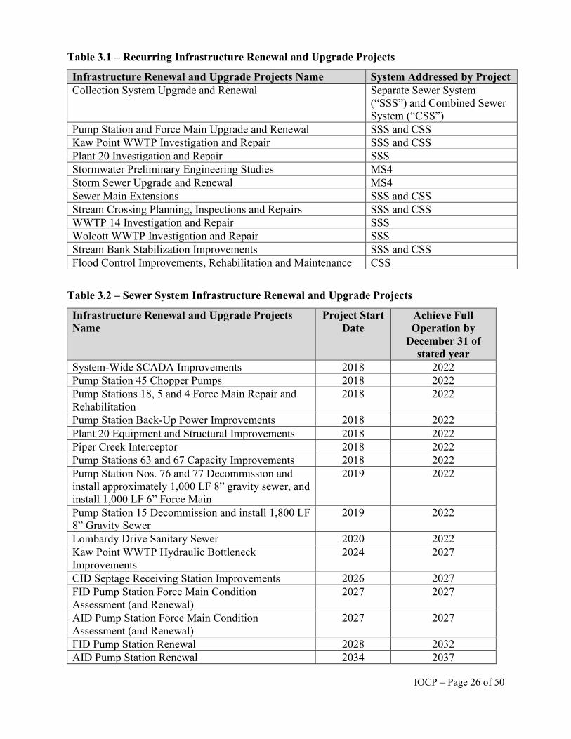
Table 3.1 – Recurring Infrastructure Renewal and Upgrade Projects
Infrastructure Renewal and Upgrade Projects Name System Addressed by Project Collection System Upgrade and Renewal Separate Sewer System
(“SSS”) and Combined Sewer System (“CSS”)
Pump Station and Force Main Upgrade and Renewal SSS and CSS Kaw Point WWTP Investigation and Repair SSS and CSS Plant 20 Investigation and Repair SSS Stormwater Preliminary Engineering Studies MS4 Storm Sewer Upgrade and Renewal MS4 Sewer Main Extensions SSS and CSS Stream Crossing Planning, Inspections and Repairs SSS and CSS WWTP 14 Investigation and Repair SSS Wolcott WWTP Investigation and Repair SSS Stream Bank Stabilization Improvements SSS and CSS Flood Control Improvements, Rehabilitation and Maintenance CSS
Table 3.2 – Sewer System Infrastructure Renewal and Upgrade Projects
Infrastructure Renewal and Upgrade Projects Name
Project Start Date
Achieve Full Operation by
December 31 of stated year
System-Wide SCADA Improvements 2018 2022 Pump Station 45 Chopper Pumps 2018 2022 Pump Stations 18, 5 and 4 Force Main Repair and Rehabilitation
2018 2022
Pump Station Back-Up Power Improvements 2018 2022 Plant 20 Equipment and Structural Improvements 2018 2022 Piper Creek Interceptor 2018 2022 Pump Stations 63 and 67 Capacity Improvements 2018 2022 Pump Station Nos. 76 and 77 Decommission and install approximately 1,000 LF 8” gravity sewer, and install 1,000 LF 6” Force Main
2019 2022
Pump Station 15 Decommission and install 1,800 LF 8” Gravity Sewer
2019 2022
Lombardy Drive Sanitary Sewer 2020 2022 Kaw Point WWTP Hydraulic Bottleneck Improvements
2024 2027
CID Septage Receiving Station Improvements 2026 2027 FID Pump Station Force Main Condition Assessment (and Renewal)
2027 2027
AID Pump Station Force Main Condition Assessment (and Renewal)
2027 2027
FID Pump Station Renewal 2028 2032 AID Pump Station Renewal 2034 2037
IOCP – Page 26 of 50
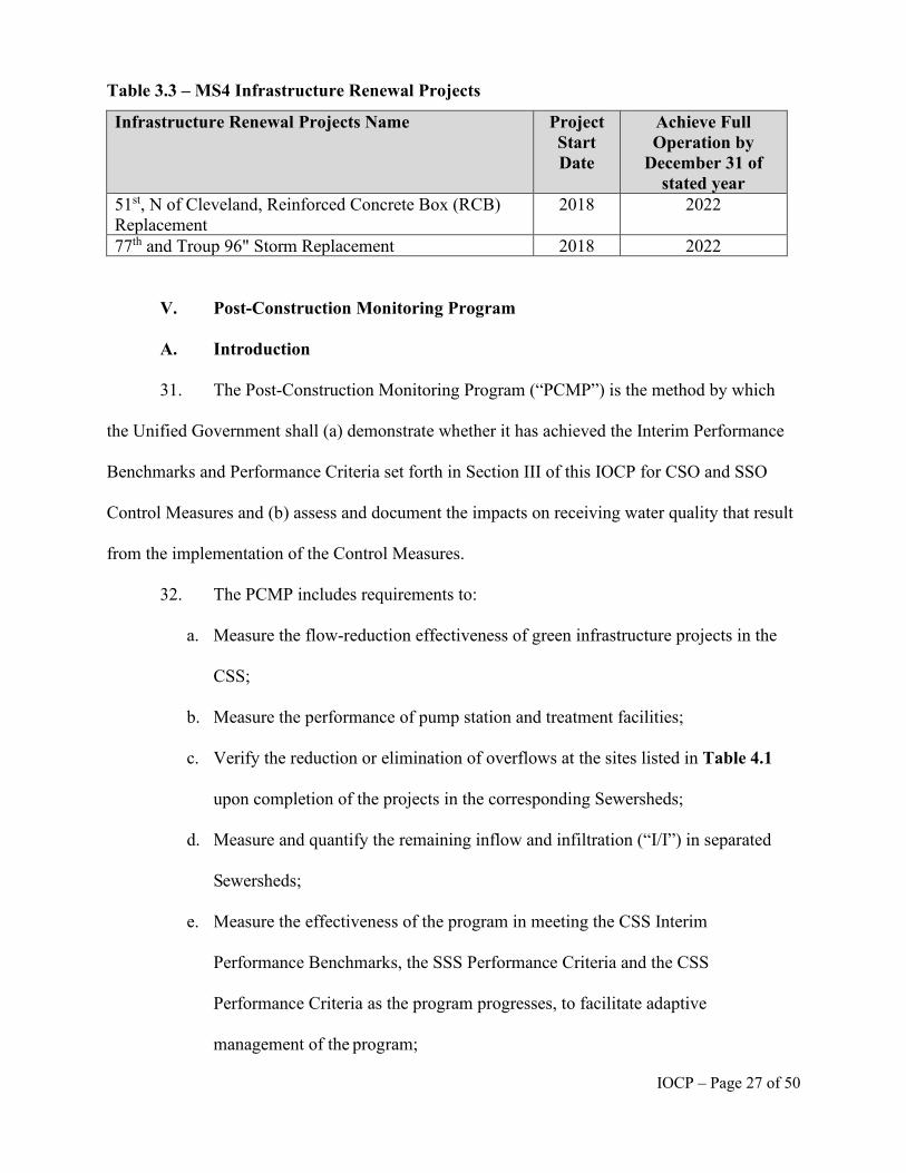
Table 3.3 – MS4 Infrastructure Renewal Projects
Infrastructure Renewal Projects Name Project Start Date
Achieve Full Operation by
December 31 of stated year
51st, N of Cleveland, Reinforced Concrete Box (RCB) Replacement
2018 2022
77th and Troup 96" Storm Replacement 2018 2022
V. Post-Construction Monitoring Program
A. Introduction
31. The Post-Construction Monitoring Program (“PCMP”) is the method by which
the Unified Government shall (a) demonstrate whether it has achieved the Interim Performance
Benchmarks and Performance Criteria set forth in Section III of this IOCP for CSO and SSO
Control Measures and (b) assess and document the impacts on receiving water quality that result
from the implementation of the Control Measures.
32. The PCMP includes requirements to:
a. Measure the flow-reduction effectiveness of green infrastructure projects in the
CSS;
b. Measure the performance of pump station and treatment facilities;
c. Verify the reduction or elimination of overflows at the sites listed in Table 4.1
upon completion of the projects in the corresponding Sewersheds;
d. Measure and quantify the remaining inflow and infiltration (“I/I”) in separated
Sewersheds;
e. Measure the effectiveness of the program in meeting the CSS Interim
Performance Benchmarks, the SSS Performance Criteria and the CSS
Performance Criteria as the program progresses, to facilitate adaptive
management of the program;
IOCP – Page 27 of 50
f. Update and re-calibrate the Sewer System hydraulic models based on post-
construction monitoring; and
g. Physically verify SSO events by monitoring the emergency relief structures and
known and model-predicted manhole overflows listed in Table 4.2.
B. Flow Monitoring
33. This PCMP shall supplement the Unified Government’s existing
wastewater system monitoring, including monitoring pursuant to Unified Government’s
National Pollutant Discharge Elimination System (“NPDES”) Permits, and the Unified
Government shall continue Permit-required flow monitoring. Under this PCMP, the
Unified Government shall perform flow monitoring at key facilities and locations in the
SSS and CSS during program implementation. The Unified Government shall utilize the
same flow monitoring locations for post-monitoring that were utilized for hydraulic
model calibration or other pre-construction monitoring to the maximum extent
practicable. The flow data collected from these locations will enable a comparison of
post-construction conditions with the baseline conditions of the hydraulic model
calibrated during the development of the IOCP.
34. The Unified Government shall perform flow monitoring of major
constructed facilities upon start-up of those facilities as detailed below. Major constructed
facilities include Pump Station improvements, high rate treatment facilities, and upgrades
to existing Wastewater Treatment Plants (“WWTP”).
35. The Unified Government shall perform flow monitoring as detailed below
to measure and evaluate the performance of SSO and CSO Control Measures, green
infrastructure and sewer separation for the reduction of wet weather overflow volumes at
the locations listed in Tables 4.1 and 4.2 below. Green infrastructure will include those in
IOCP – Page 28 of 50
support of sewer separation projects and those that are stand-alone, if the project objective
includes reduction of CSOs.
36. The Unified Government shall use level sensors, and where appropriate, flow
meters or other reliable automated technology to monitor manhole level and verify the
elimination of SSO activations up to the 2-year and 5-year design storm events using the
calibrated hydraulic models consistent with Section III, Table 1.2, at the sites listed in Table 4.2.
37. The Unified Government shall develop specific locations for pre-construction
short-term flow monitoring programs as necessary for the planning for these Sewer System
Control Measures. These locations shall be highly specific to individual larger projects or groups
of smaller projects included in a single construction contract, as appropriate.
38. The Unified Government shall include information regarding the flow monitoring
locations, a summary of the results, and any conclusions drawn from the flow monitoring
regarding the effectiveness of the project or series of projects, and a plan of action for flow
monitoring for the upcoming reporting year in the Annual Report submitted pursuant to Section
XII of the Consent Decree (Reporting, Certification and Approval of Submittals).
C. PCMP for CSO Controls
39. Kaw Point WWTP. In the corresponding spring/summer period following the
Achieve Full Operation date for each CSO Control Measure at the Kaw Point WWTP, the
Unified Government shall perform short-term (90 days minimum) flow monitoring within the
interceptor where wastewater flows from the SSS enter the CSS, and permanent monitoring at
the Kaw Point WWTP of influent flows to the plant, flows through the high-rate primary settling
basins and through the new disinfection process, plus those flows receiving primary and
secondary treatment and disinfection through the current process path. The Unified Government
IOCP – Page 29 of 50
shall also develop an updated wet weather plant operations protocol after completion of
CSO Control Measures at the Kaw Point WWTP.
40. AID, FID, and CID Pump Stations. Each of these three critical CSS Pump
Stations shall be equipped with new SCADA systems and rehabilitated to enable each
Pump Station to reach its original design capacity as follows: FID capacity to 30.1 MGD,
AID capacity to 53.4 MGD, and CID capacity to 11.5 MGD. In the corresponding
spring/summer period following completion of each CSS Pump Station rehabilitation, the
Unified Government shall use short-term (90 days minimum) flow meters within the
interceptor where flows from the SSS enter the CSS, and permanent flow meters to
continuously measure the flow pumped from each Pump Station in order to allow for the
calculation of the total combined flow capture volume and capture percentage of the
system in each Pump Station Sewershed and assist with calibration and validation of the
CSS hydraulic model.
41. The Unified Government shall perform post-construction short-term (90
days minimum) flow metering at the sites listed in Table 4.1 in the corresponding
spring/summer period following the Achieve Full Operation date for the relevant Control
Measures to evaluate flow reduction effectiveness of the Control Measures. In separated
areas, the Unified Government shall use flow monitoring to quantify the remaining I/I in
the SSS to allow better calibration of the wet-weather response in the system hydraulic
model.
42. Summary. Data collected by the Unified Government through flow
monitoring of selected CSO Outfalls, selected Sewer System locations, and major wet
weather facilities, such as WWTPs, Pump Stations and high-rate treatment facilities shall
IOCP – Page 30 of 50
be used to determine the level of wet-weather capture achieved as implementation progresses.
This data will support the following activities:
a. Characterization of sewer flow data for evaluation of long-term Sewer System
performance;
b. Collection of information on overflows at critical CSS diversion structures and
from CSO outfalls;
c. Determination of remaining I/I in the SSS that is tributary to the CSS for
hydraulic model update and re-calibration;
d. Collection of additional data, such as performance at the AID, FID, and CID
Pump Stations to ensure desired pumping capacities are restored;
e. Collection of flow data for potential use in future design efforts related to
controlling both CSS and SSS Overflows;
f. Operation and maintenance actions to further control wet weather discharges and
NPDES compliance; and
g. Collection of data for hydraulic model updates to support adaptive management of
the CSO Control Measures to achieve Interim Performance Benchmarks and
Performance Criteria and regulatory requirements.
43. The suite of CSS flow monitoring locations is presented in Table 4.1, below. The
monitoring locations were selected to correspond to where overflow reduction is expected from
CSO Control Measures as well as locations to evaluate long-term collection system performance
and wet-weather capture volumes using the calibrated hydraulic model.
D. PCMP for SSO Controls
44. The following sections describe the PCMP for SSO Control Measures. The
effectiveness of sanitary sewer system improvements shall be demonstrated utilizing the sewer
IOCP – Page 31 of 50
system hydraulic model developed by the Unified Government and through direct
observation of SSOs at the locations identified in Table 4.2, below, representing the
emergency relief structures and manholes that are susceptible to SSOs during significant
storm events. The Unified Government shall conduct short-term level monitoring at these
Sewer System locations for not less than 180 days commencing no later than April 1,
2021, to collect information to evaluate the effectiveness of the SSO Control Measures
that will be implemented to achieve the targeted level of service. The flow monitoring
data collected shall be used to re-calibrate and validate the hydraulic modeling of the
sanitary sewer system.
45. Pump Station Overflows. A number of modeled and non-modeled Pump
Stations have emergency relief structures with diversions either within the wet well or the
manhole immediately upstream of the Pump Station. The Unified Government shall
complete level sensing on the overflow lines from these Pump Station emergency relief
structures to confirm the occurrence of any overflows at each location as indicated in the
following paragraph. The Unified Government shall use this data to verify the level of
service provided by the various SSO Control Measures using the calibrated hydraulic
models.
46. The Unified Government has known emergency relief structures within its
Sewer System to control surcharging in the system and protect adjacent homes from
basement backups. Within six months of the Achieve Full Operation date for each SSO
Control Measure in the separate sewer system tributary to each emergency relief structure
the Unified Government shall commence long-term activation monitoring at the
emergency relief structures listed in Table 4.2, below, and continue that monitoring for at
least two years, to identify the effectiveness of such SSO Control Measures. Should the
IOCP – Page 32 of 50
annual rainfall in any of these years be more than 25-percent below or above the historical
annual average, monitoring shall be extended for a third year. The Unified Government shall use
tools, such as level-sensing devices, to monitor these manholes and log overflow events to
provide data for recalibrating the hydraulic models to verify the 2-year and 5-year design storm
level of service. Recorded data from level-sensing or other appropriate equipment that shows
liquid levels exceeding the invert elevation of the diversion pipes shall be used to identify
overflow events.
47. Rainfall Monitoring. Detailed analysis of precipitation data is necessary as a
companion to the flow monitoring results to fully update the hydraulic model’s response to
rainfall and evaluate compliance with the Performance Criteria. Precipitation data of interest
consists of total rainfall depth, duration, intensity and event distribution. Precipitation data will
be sampled at 5-minute to 15-minute intervals to correspond with flow metering time steps.
48. The source of rainfall data will be rainfall gauges installed at an average density
of not less than one gauge per 5 square miles throughout the Unified Government wastewater
sewer service area to analyze SSO and Pump Station overflows to evaluate compliance with the
SSS Performance Criteria in Table 1.2 of this IOCP. To analyze pre- and post-construction
project performance data, the source of rainfall data will be rainfall gauges, including some
permanent rainfall gauges, installed at an average density of not less than one per 5 square miles
in the wastewater basin tributary to each project. Additional rainfall data for localized, small-
scale construction projects will be predominantly temporary rainfall gauges placed within the
sewer service areas directly tributary to the flow monitoring area during the monitoring period.
The Unified Government shall utilize the same rainfall gauge locations for post-construction
monitoring that were utilized for baseline or other pre-construction monitoring to the maximum
extent practicable.
IOCP – Page 33 of 50
E. Water Quality Monitoring and Assessment and PCMP Reports
49. Water Quality Monitoring. The Unified Government shall perform water quality
monitoring and analysis three times during IOCP implementation. The water quality
monitoring program shall include: an initial baseline sampling and monitoring period in
the 2022 recreational season; a second mid-program sampling and monitoring period in
2033 after completion of the Wolcott WWTP and re-route of flow from PS 50, sewer
separation projects in the Argentine and Armourdale Basins, and green infrastructure in
CSO 19; and a final sampling and monitoring period at the completion of all CSO and
SSO Control Measures in 2045.
50. Sampling Location and Parameters. The Unified Government shall
conduct ambient stream monitoring at up to eleven locations including sites in the Kansas
River, Missouri River, Jersey Creek, Mattoon Creek and Turkey Creek, and CSO
monitoring at two overflows within the CSS, as specified in Table 2-1 and Figure 2-1 in
Appendix D, Water Quality Monitoring Program Sampling and Analysis Plan, dated
February 5, 2013, of the Unified Government’s March 2013 Sewer System Evaluation
(“SSE”) Work Plan. For the Parties’ convenience, the Unified Government’s Water
Quality Monitoring Program Sampling and Analysis Plan, dated February 5, 2013 is
attached as Appendix A of this IOCP. These locations were selected to characterize water
quality conditions upstream and downstream of CSO impacts and support the
development and calibration of water quality models. Site accessibility and safety were
also considered in location selection.
51. The Unified Government shall record field measurements of water temperature,
pH, and dissolved oxygen at each monitoring site using calibrated water quality meters.
Concurrent with field measurements, observations shall be made and recorded at each
IOCP – Page 34 of 50
monitoring location related to weather, aesthetic impacts and evidence of recreational use. Water
samples for laboratory analysis shall be collected immediately following field measurements at a
monitoring site. The Unified Government shall conduct sampling during the months of April
through October, to coincide with the recreation season, in accordance with the sampling
procedures and protocols stated in Appendix D to the Unified Government’s 2013 SSE Work
Plan (Appendix A to this IOCP). The samples at each site shall be analyzed for the parameters
listed in Table 2-2 to Appendix A to this IOCP (SSE Work Plan, Appendix D).
52. Control Measures Report. The Unified Government shall use data from the PCMP
to evaluate the effectiveness of SSO and CSO Control Measures identified in Tables 1.1 and 2.1
in Section III of this IOCP to determine whether the SSS Performance Criteria identified in
Section III, Table 1.2, and the CSS Interim Performance Benchmarks identified in Table 2.2,
have been achieved. The Control Measures Report detailing the results and progress of the
PCMP shall be included in the Annual Report, submitted pursuant to Section XII of the Consent
Decree (Reporting, Certification and Approval of Submittals), for the Calendar Year following
each Achieve Full Operation deadline for SSO Control Measures in Table 1.1 and each CSS
Interim Performance Benchmark period in Table 2.2. This report shall include a summary of
SSS and CSS basin performance to-date, consisting of:
a. Status of Sewer System Control Measures implementation;
b. SSS and CSS flow monitoring performed;
c. Summary of flow monitoring results obtained in the report year;
d. Documentation of model modifications, re-calibration and re-verification
performed in the report year;
IOCP – Page 35 of 50
e. Identification and documentation of model-based SSO and CSO reductions
achieved by Control Measures and applicable Infrastructure Projects constructed up
to and including the report year; and
f. Comparison of results verified by post-construction flow monitoring versus
results predicted by the model at the time of IOCP development.
53. If, following post-construction monitoring, the analysis indicates that any SSO
Control Measure identified in Table 1.1, above, fails to achieve the Level of Service identified in
Table 1.2, or that one or more of the CSS Interim Performance Benchmarks in Table 2.2, will
not be achieved by the dates specified, the Unified Government shall submit to EPA, for review
and approval, a SCP in accordance with Section III of this IOCP as part of the Control Measures
Report.
54. Water Quality Standards Assessment. In addition to the evaluation of the
Performance Criteria, the Unified Government shall collect information on the impact of
remaining CSOs on achievement of water quality standards and the current NPDES
permit requirements. The sampling data and water quality model should also evaluate the
extent to which the remaining CSOs impact achievement of water quality criteria if
background sources of pollution were eliminated and reduced.
55. A goal of collecting sampling data is to determine the effects of the
remaining CSOs on receiving water quality and achievement of prevailing water quality
standards. For example, are the CSO discharges causing exceedances of water quality
criteria? Or, to the extent that criteria are already being exceeded due to upstream
sources, are the remaining CSOs increasing the magnitude of exceedances of water
quality criteria? Have enough sampling results been collected to calculate a geometric
mean E. coli concentration consistent with applicable water quality standards? Whether
IOCP – Page 36 of 50
the water quality standards are achieved shall be decided on a case by case basis in consultation
with the EPA and the Kansas Department of Health and Environment (“KDHE”).
56. Final Post-Construction Monitoring Report. No later than December 31, 2046 the
Unified Government shall submit to the EPA a final Post-Construction Monitoring Report for
EPA review and approval in accordance with Section XII of the Consent Decree, which shall:
a. Demonstrate that the Unified Government completed the requirements of the
PCMP;
b. Evaluate whether the Sewer System Control Measures implemented pursuant to
this IOCP meet the Performance Criteria of the IOCP;
c. Include a Water Quality Standards Assessment Report Related to Post-
Construction Compliance Monitoring, setting forth its conclusions as to whether
the Unified Government is meeting the NPDES permit-based requirements and is
achieving compliance with applicable water quality standards, including whether
the Sewer System Control Measures pursuant to Section III of this IOCP, as
constructed, operated, or otherwise implemented, have achieved the Performance
Criteria, and the Objectives set forth in Section III of the Consent Decree,
specifically with regard to: (i) full compliance with NPDES permits, the CWA, the
Kansas public health statutes, and their regulations; (ii) compliance with the CSO
Policy, including compliance with applicable state water quality standards; (iii) the
elimination of SSOs and Unauthorized CSOs; and (iv) the elimination of bypasses
prohibited by 40 C.F.R. § 122.41(m);
d. Summarize the data collected during the entirety of the monitoring period and
include any new data relevant to the evaluation that the Unified Government did
not previously submit to EPA;
IOCP – Page 37 of 50
e. If model or monitoring results show that the Unified Government’s Sewer System
Control Measures did not meet the Performance Criteria or Objectives, the
Unified Government shall identify and describe in detail deficiencies or
performance-limiting factors in system design, process, operations, and
maintenance that may have limited the ability of the Sewer System Control
Measures to achieve their intended performance; and
f. Thereafter, the Unified Government shall identify and describe in detail all
necessary and feasible Corrective Measures, alternative operating strategies and
additional facilities and processes necessary to meet the Performance Criteria and
Objectives.
IOCP – Page 38 of 50
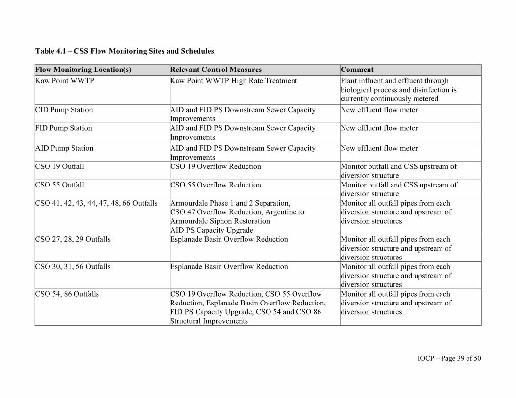
Table 4.1 – CSS Flow Monitoring Sites and Schedules
Flow Monitoring Location(s) Relevant Control Measures Comment Kaw Point WWTP Kaw Point WWTP High Rate Treatment Plant influent and effluent through
biological process and disinfection is currently continuously metered
CID Pump Station AID and FID PS Downstream Sewer Capacity Improvements
New effluent flow meter
FID Pump Station AID and FID PS Downstream Sewer Capacity Improvements
New effluent flow meter
AID Pump Station AID and FID PS Downstream Sewer Capacity Improvements
New effluent flow meter
CSO 19 Outfall CSO 19 Overflow Reduction Monitor outfall and CSS upstream of diversion structure
CSO 55 Outfall CSO 55 Overflow Reduction Monitor outfall and CSS upstream of diversion structure
CSO 41, 42, 43, 44, 47, 48, 66 Outfalls Armourdale Phase 1 and 2 Separation, CSO 47 Overflow Reduction, Argentine to Armourdale Siphon Restoration AID PS Capacity Upgrade
Monitor all outfall pipes from each diversion structure and upstream of diversion structures
CSO 27, 28, 29 Outfalls Esplanade Basin Overflow Reduction Monitor all outfall pipes from each diversion structure and upstream of diversion structures
CSO 30, 31, 56 Outfalls Esplanade Basin Overflow Reduction Monitor all outfall pipes from each diversion structure and upstream of diversion structures
CSO 54, 86 Outfalls CSO 19 Overflow Reduction, CSO 55 Overflow Reduction, Esplanade Basin Overflow Reduction, FID PS Capacity Upgrade, CSO 54 and CSO 86 Structural Improvements
Monitor all outfall pipes from each diversion structure and upstream of diversion structures
IOCP – Page 39 of 50
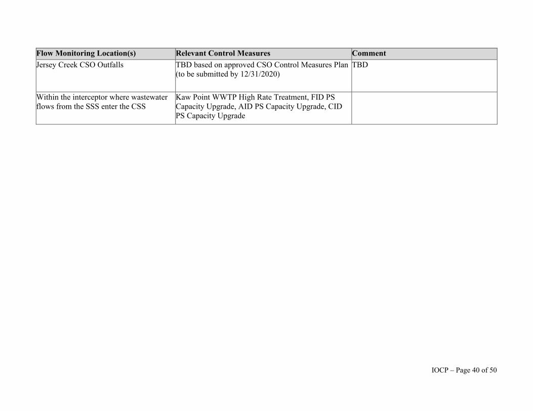
Flow Monitoring Location(s) Relevant Control Measures Comment Jersey Creek CSO Outfalls TBD based on approved CSO Control Measures Plan
(to be submitted by 12/31/2020) TBD
Within the interceptor where wastewater flows from the SSS enter the CSS
Kaw Point WWTP High Rate Treatment, FID PS Capacity Upgrade, AID PS Capacity Upgrade, CID PS Capacity Upgrade
IOCP – Page 40 of 50
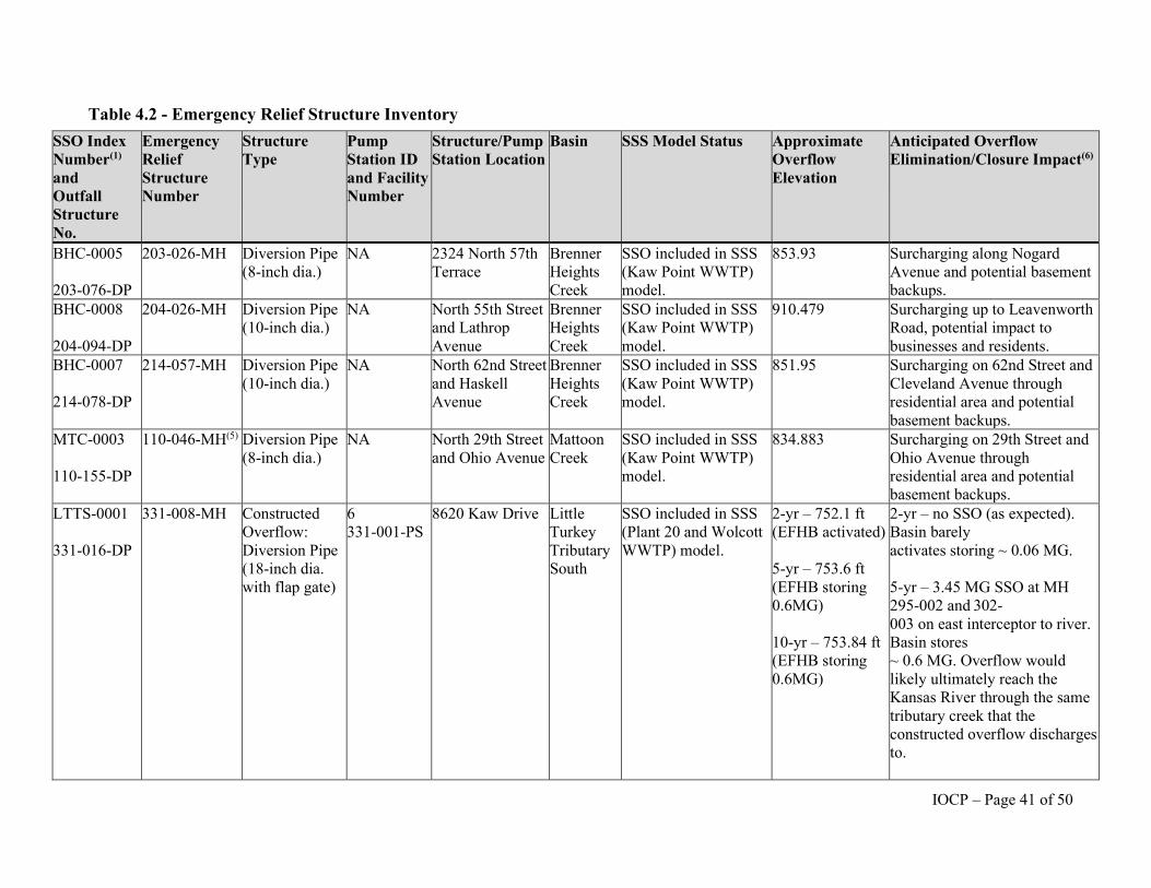
Table 4.2 - Emergency Relief Structure Inventory SSO Index Number(1)
and Outfall Structure No.
Emergency Relief Structure Number
Structure Type
Pump Station ID and Facility Number
Structure/Pump Station Location
Basin SSS Model Status Approximate Overflow Elevation
Anticipated Overflow Elimination/Closure Impact(6)
BHC-0005
203-076-DP
203-026-MH Diversion Pipe (8-inch dia.)
NA 2324 North 57th Terrace
Brenner Heights Creek
SSO included in SSS (Kaw Point WWTP) model.
853.93 Surcharging along Nogard Avenue and potential basement backups.
BHC-0008
204-094-DP
204-026-MH Diversion Pipe (10-inch dia.)
NA North 55th Street and Lathrop Avenue
Brenner Heights Creek
SSO included in SSS (Kaw Point WWTP) model.
910.479 Surcharging up to Leavenworth Road, potential impact to businesses and residents.
BHC-0007
214-078-DP
214-057-MH Diversion Pipe (10-inch dia.)
NA North 62nd Street and Haskell Avenue
Brenner Heights Creek
SSO included in SSS (Kaw Point WWTP) model.
851.95 Surcharging on 62nd Street and Cleveland Avenue through residential area and potential basement backups.
MTC-0003
110-155-DP
110-046-MH(5) Diversion Pipe (8-inch dia.)
NA North 29th Street and Ohio Avenue
Mattoon Creek
SSO included in SSS (Kaw Point WWTP) model.
834.883 Surcharging on 29th Street and Ohio Avenue through residential area and potential basement backups.
LTTS-0001
331-016-DP
331-008-MH Constructed Overflow: Diversion Pipe (18-inch dia. with flap gate)
6 331-001-PS
8620 Kaw Drive Little Turkey Tributary South
SSO included in SSS (Plant 20 and Wolcott WWTP) model.
2-yr – 752.1 ft (EFHB activated)
5-yr – 753.6 ft (EFHB storing 0.6MG)
10-yr – 753.84 ft (EFHB storing 0.6MG)
2-yr – no SSO (as expected). Basin barely activates storing ~ 0.06 MG.
5-yr – 3.45 MG SSO at MH 295-002 and 302-003 on east interceptor to river. Basin stores ~ 0.6 MG. Overflow would likely ultimately reach the Kansas River through the same tributary creek that the constructed overflow discharges to.
IOCP – Page 41 of 50
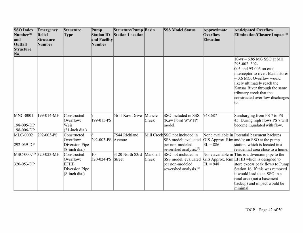
SSO Index Number(1)
and Outfall Structure No.
Emergency Relief Structure Number
Structure Type
Pump Station ID and Facility Number
Structure/Pump Station Location
Basin SSS Model Status Approximate Overflow Elevation
Anticipated Overflow Elimination/Closure Impact(6)
10-yr – 6.85 MG SSO at MH 295-002, 302-003 and 95-003 on east interceptor to river. Basin stores ~ 0.6 MG. Overflow would likely ultimately reach the Kansas River through the same tributary creek that the constructed overflow discharges to.
MNC-0001
198-005-DP 198-006-DP
199-014-MH Constructed Overflow: Weir (21-inch dia.)
7 199-015-PS
5611 Kaw Drive Muncie Creek
SSO included in SSS (Kaw Point WWTP) model.
748.687 Surcharging from PS 7 to PS 45. During high flows PS 7 will become inundated with flow.
MLC-0002
292-039-DP
292-003-PS Constructed Overflow: Diversion Pipe (8-inch dia.)
8 292-003-PS
7544 Richland Avenue
Mill Creek SSO not included in SSS model; evaluated per non-modeled sewershed analysis.(2)
None available in GIS Approx. Rim EL = 886
Potential basement backups and/or an SSO at the pump station, which is located in a residential area close to a home.
MSC-0007(1)
320-053-DP
320-023-MH Constructed Overflow: EFHB Diversion Pipe (8-inch dia.)
10 320-024-PS
3120 North 83rd Street
Marshall Creek
SSO not included in SSS model; evaluated per non-modeled sewershed analysis.(2)
None available in GIS Approx. Rim EL = 948
This is a diversion pipe to the EFHB which is designed to store excess peak flows to Pump Station 16. If this was removed it would lead to an SSO in a rural area (not a basement backup) and impact would be minimal.
IOCP – Page 42 of 50
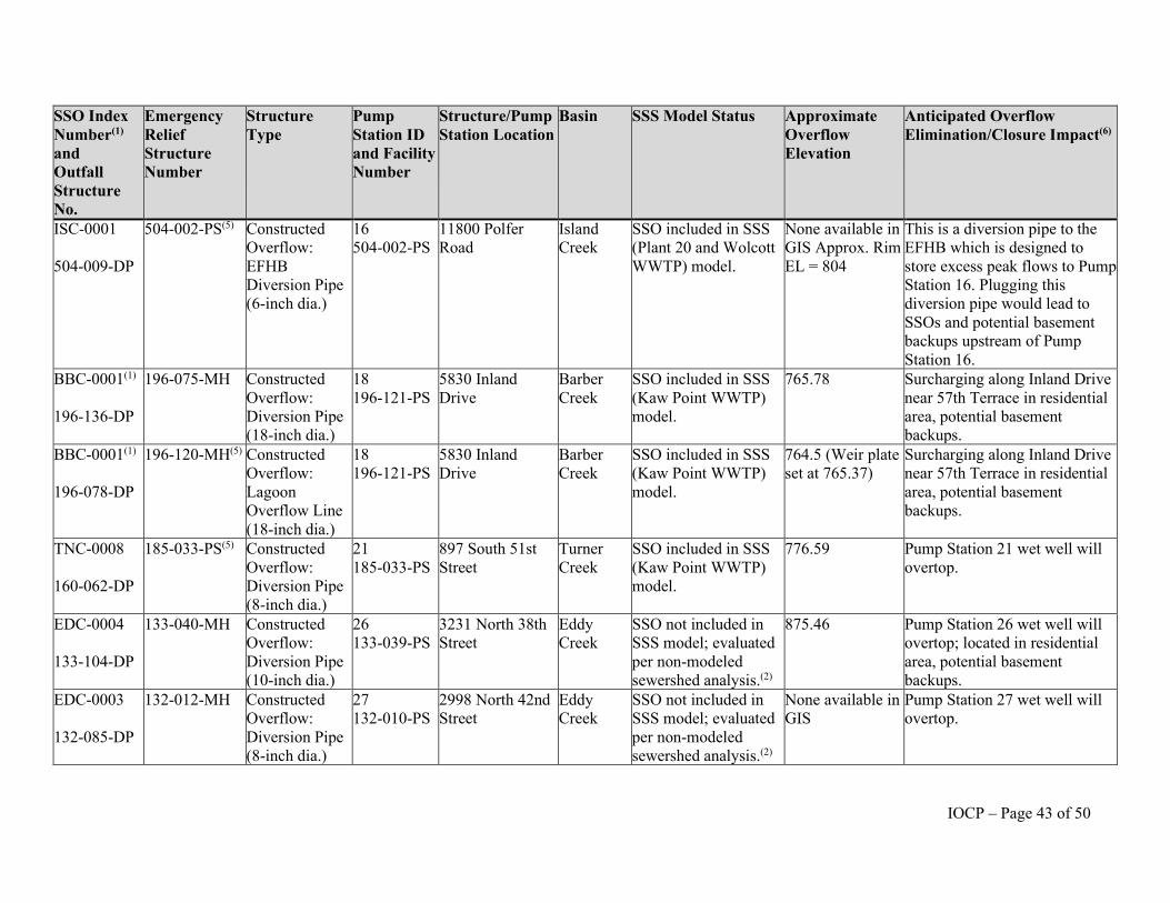
SSO Index Number(1)
and Outfall Structure No.
Emergency Relief Structure Number
Structure Type
Pump Station ID and Facility Number
Structure/Pump Station Location
Basin SSS Model Status Approximate Overflow Elevation
Anticipated Overflow Elimination/Closure Impact(6)
ISC-0001
504-009-DP
504-002-PS(5) Constructed Overflow: EFHB Diversion Pipe (6-inch dia.)
16 504-002-PS
11800 Polfer Road
Island Creek
SSO included in SSS (Plant 20 and Wolcott WWTP) model.
None available in GIS Approx. Rim EL = 804
This is a diversion pipe to the EFHB which is designed to store excess peak flows to Pump Station 16. Plugging this diversion pipe would lead to SSOs and potential basement backups upstream of Pump Station 16.
BBC-0001(1)
196-136-DP
196-075-MH Constructed Overflow: Diversion Pipe (18-inch dia.)
18 196-121-PS
5830 Inland Drive
Barber Creek
SSO included in SSS (Kaw Point WWTP) model.
765.78 Surcharging along Inland Drive near 57th Terrace in residential area, potential basement backups.
BBC-0001(1)
196-078-DP
196-120-MH(5) Constructed Overflow: Lagoon Overflow Line (18-inch dia.)
18 196-121-PS
5830 Inland Drive
Barber Creek
SSO included in SSS (Kaw Point WWTP) model.
764.5 (Weir plate set at 765.37)
Surcharging along Inland Drive near 57th Terrace in residential area, potential basement backups.
TNC-0008
160-062-DP
185-033-PS(5) Constructed Overflow: Diversion Pipe (8-inch dia.)
21 185-033-PS
897 South 51st Street
Turner Creek
SSO included in SSS (Kaw Point WWTP) model.
776.59 Pump Station 21 wet well will overtop.
EDC-0004
133-104-DP
133-040-MH Constructed Overflow: Diversion Pipe (10-inch dia.)
26 133-039-PS
3231 North 38th Street
Eddy Creek
SSO not included in SSS model; evaluated per non-modeled sewershed analysis.(2)
875.46 Pump Station 26 wet well will overtop; located in residential area, potential basement backups.
EDC-0003
132-085-DP
132-012-MH Constructed Overflow: Diversion Pipe (8-inch dia.)
27 132-010-PS
2998 North 42nd Street
Eddy Creek
SSO not included in SSS model; evaluated per non-modeled sewershed analysis.(2)
None available in GIS
Pump Station 27 wet well will overtop.
IOCP – Page 43 of 50
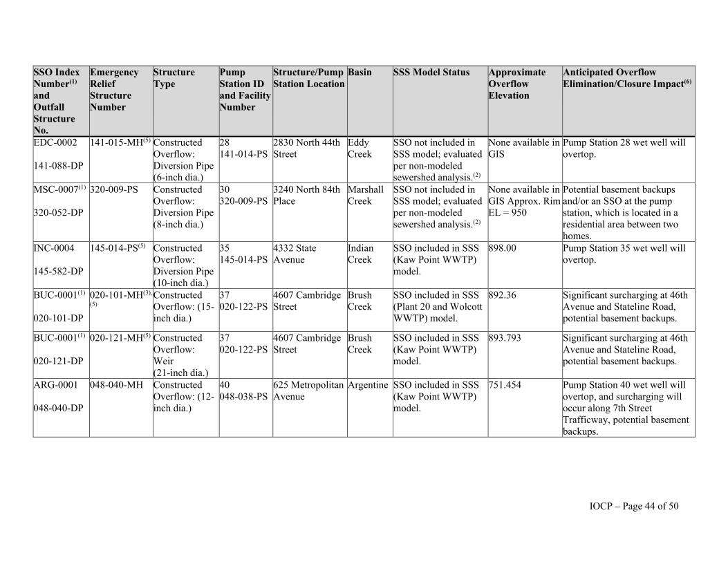
SSO Index Number(1)
and Outfall Structure No.
Emergency Relief Structure Number
Structure Type
Pump Station ID and Facility Number
Structure/Pump Station Location
Basin SSS Model Status Approximate Overflow Elevation
Anticipated Overflow Elimination/Closure Impact(6)
EDC-0002
141-088-DP
141-015-MH(5) Constructed Overflow: Diversion Pipe (6-inch dia.)
28 141-014-PS
2830 North 44th Street
Eddy Creek
SSO not included in SSS model; evaluated per non-modeled sewershed analysis.(2)
None available in GIS
Pump Station 28 wet well will overtop.
MSC-0007(1)
320-052-DP
320-009-PS Constructed Overflow: Diversion Pipe (8-inch dia.)
30 320-009-PS
3240 North 84th Place
Marshall Creek
SSO not included in SSS model; evaluated per non-modeled sewershed analysis.(2)
None available in GIS Approx. Rim EL = 950
Potential basement backups and/or an SSO at the pump station, which is located in a residential area between two homes.
INC-0004
145-582-DP
145-014-PS(5) Constructed Overflow: Diversion Pipe (10-inch dia.)
35 145-014-PS
4332 State Avenue
Indian Creek
SSO included in SSS (Kaw Point WWTP) model.
898.00 Pump Station 35 wet well will overtop.
BUC-0001(1)
020-101-DP
020-101-MH(3),
(5) Constructed Overflow: (15-inch dia.)
37 020-122-PS
4607 Cambridge Street
Brush Creek
SSO included in SSS (Plant 20 and Wolcott WWTP) model.
892.36 Significant surcharging at 46th Avenue and Stateline Road, potential basement backups.
BUC-0001(1)
020-121-DP
020-121-MH(5) Constructed Overflow: Weir (21-inch dia.)
37 020-122-PS
4607 Cambridge Street
Brush Creek
SSO included in SSS (Kaw Point WWTP) model.
893.793 Significant surcharging at 46th Avenue and Stateline Road, potential basement backups.
ARG-0001
048-040-DP
048-040-MH Constructed Overflow: (12-inch dia.)
40 048-038-PS
625 Metropolitan Avenue
Argentine SSO included in SSS (Kaw Point WWTP) model.
751.454 Pump Station 40 wet well will overtop, and surcharging will occur along 7th Street Trafficway, potential basement backups.
IOCP – Page 44 of 50
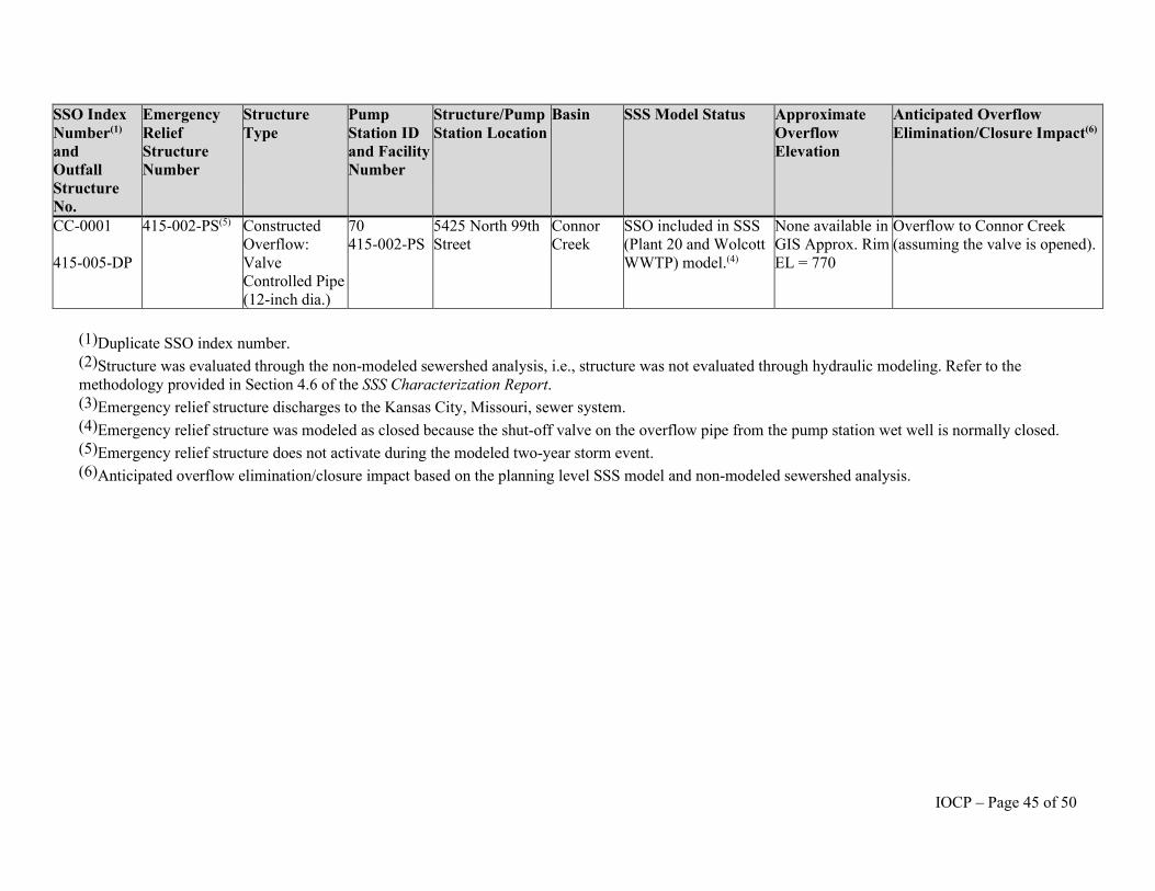
SSO Index Number(1)
and Outfall Structure No.
Emergency Relief Structure Number
Structure Type
Pump Station ID and Facility Number
Structure/Pump Station Location
Basin SSS Model Status Approximate Overflow Elevation
Anticipated Overflow Elimination/Closure Impact(6)
CC-0001
415-005-DP
415-002-PS(5) Constructed Overflow: Valve Controlled Pipe (12-inch dia.)
70 415-002-PS
5425 North 99th Street
Connor Creek
SSO included in SSS (Plant 20 and Wolcott WWTP) model.(4)
None available in GIS Approx. Rim EL = 770
Overflow to Connor Creek (assuming the valve is opened).
(1)Duplicate SSO index number. (2)Structure was evaluated through the non-modeled sewershed analysis, i.e., structure was not evaluated through hydraulic modeling. Refer to the methodology provided in Section 4.6 of the SSS Characterization Report. (3)Emergency relief structure discharges to the Kansas City, Missouri, sewer system. (4)Emergency relief structure was modeled as closed because the shut-off valve on the overflow pipe from the pump station wet well is normally closed. (5)Emergency relief structure does not activate during the modeled two-year storm event. (6)Anticipated overflow elimination/closure impact based on the planning level SSS model and non-modeled sewershed analysis.
IOCP – Page 45 of 50
VI. Summary of Reporting Requirements
57. Beginning with Calendar Year 2020, the Unified Government may include all
information required pursuant to Paragraphs 60(b) and 60(c) of the Consent Decree for the
period of January 1 through December 31 each year in the Annual Report, and cease submitting
a Semiannual Report on August 15. The first such Annual Report shall be submitted for the
period from January 1 to December 31, 2020, no later than February 28, 2021, and shall include
all information required by Paragraphs 60(b) and 60(c) of the Consent Decree. Succeeding
Annual Reports shall be submitted no later than February 28 of each year until termination of the
Consent Decree.
58. The information in Table 5.1, below, is a summary of the reporting requirements
in Sections III through V of this IOCP and the corresponding reporting provision of Section XII
(Reporting, Certification and Approval of Submittals) of the Consent Decree. This information is
provided for the convenience of the Parties and does not change the underlying reporting
requirements of the Consent Decree.
59. The Unified Government shall maintain on its website until termination of the
Consent Decree an updated copy of Tables 1.1, 1.2, 2.1, 2.2, 3.2 and 3.3 in Sections III and
IV of this IOCP listing all approved Control Measures, Projects and associated schedules.
IOCP – Page 46 of 50
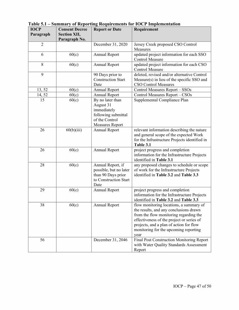
Table 5.1 – Summary of Reporting Requirements for IOCP Implementation IOCP Paragraph
Consent Decree Section XII, Paragraph No.
Report or Date Requirement
2 December 31, 2020 Jersey Creek proposed CSO Control Measures
6 60(c) Annual Report updated project information for each SSO Control Measure
8 60(c) Annual Report updated project information for each CSO Control Measure
9 90 Days prior to Construction Start Date
deleted, revised and/or alternative Control Measure(s) in lieu of the specific SSO and CSO Control Measures
13, 52 60(c) Annual Report Control Measures Report – SSOs 14, 52 60(c) Annual Report Control Measures Report – CSOs
15 60(c) By no later than August 31 immediately following submittal of the Control Measures Report
Supplemental Compliance Plan
26 60(b)(iii) Annual Report relevant information describing the nature and general scope of the expected Work for the Infrastructure Projects identified in Table 3.1
26 60(c) Annual Report project progress and completion information for the Infrastructure Projects identified in Table 3.1
28 60(c) Annual Report, if possible, but no later than 90 Days prior to Construction Start Date
any proposed changes to schedule or scope of work for the Infrastructure Projects identified in Table 3.2 and Table 3.3
29 60(c) Annual Report project progress and completion information for the Infrastructure Projects identified in Table 3.2 and Table 3.3
38 60(c) Annual Report flow monitoring locations, a summary of the results, and any conclusions drawn from the flow monitoring regarding the effectiveness of the project or series of projects, and a plan of action for flow monitoring for the upcoming reporting year
56 December 31, 2046 Final Post Construction Monitoring Report with Water Quality Standards Assessment Report
IOCP – Page 47 of 50
VII. Design Year for the Combined Sewer System
60. The following information is an excerpt from the Unified Government’s DRAFT
Combined Sewer System (CSS) Characterization Report, Unified Government of Wyandotte
County and Kansas City, Kansas Integrated Overflow Control Program, May 31, 2015. This
information is included in this IOCP for the convenience of the Parties in implementing the
IOCP.
3.3 Design Storm and Design Year Development
An evaluation of precipitation data was completed to define typical rainfall distribution
patterns and recurrence intervals. Historical precipitation data was utilized to develop design
storms and the Design Year that was applied when modeling the existing conditions and
alternative control scenarios.
There was no long-term, continuous precipitation data available directly in the CSS area.
However, continuous, long-term precipitation data for the Kansas City International (KCI)
Airport was available from the National Climatic Data Center (NCDC). The KCI Airport data set
provided 38 continuous and complete years (1973-2010) of hourly precipitation data with a
precision of 0.01-inch. Precipitation patterns are expected to be similar at KCI and within the
CSS area because of their proximity and the absence of significant landscape features, which
would cause differences.
3.3.1 Precipitation Event Characteristics
An analysis of the KCI Airport precipitation data for the 1973 to 2010 period was
conducted to define design storm events. Continuous hourly data were used to evaluate storm
event depth, intensity, and duration. For purposes of defining an “event” for use in the
precipitation data analysis, a minimum inter-event time (MIT) of 12 hours was applied to
IOCP – Page 48 of 50

delineate precipitation events. The MIT refers to a minimum period of dry weather (i.e.,
characterized by no measurable rainfall) that delineates sequential storm events.
Return periods for design storms were selected to represent a finite set of storms covering
the range of storms expected in a typical year and for incrementally sizing and assessing control
alternatives. A MIT of 12 hours was selected based on a review of literature, expectations for the
time it takes for the CSS to return to normal baseflow conditions following the cessation of
precipitation, and consistency with the MIT selected for the Kansas City, Missouri, design storm
analysis.
3.3.2 Design Storms
Using the KCI Airport data set and a 12-hour MIT, precipitation events were defined and
return periods for event precipitation depth (in) and peak hourly intensity (in/hr) were calculated
using a partial duration series consistent with the Weibull rank-order approach (McCuen, 1989).
As provided in the SSE Work Plan, Table 3-1 presents a summary of the design storm return
periods, storm depth, peak hourly intensity, and storm duration; the number of expected events in
a typical year; and the number of events exceeding the design storm in a typical year. These
values are based on averages from the precipitation record for the historical period. These eight
design storms were used to evaluate a range of CSO controls. Additional commentary on
development of the design storms is provided in Appendix A of the SSE Work Plan.
IOCP – Page 49 of 50
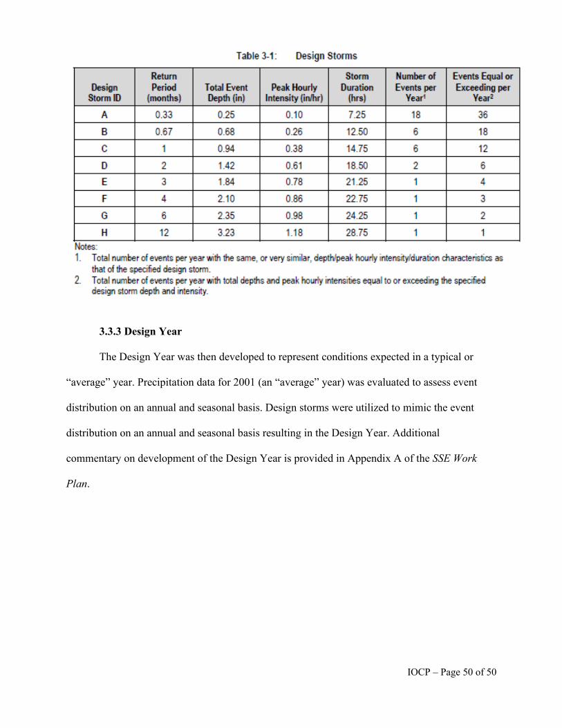
ble 3-1: Design Storms
Return $tom, Number of Events Equal or Design Period Total Event Peak Hourly Duration Events per Exceeding per
Storm 10 {months) Depth {in) Intensity (in/hr) {hrs) Year1 Year2
A 0.33 0.25 0.10 7.25 18 36
B 0.67 0.68 0.26 12.50 6 18
C 1 0.94 0.38 14.75 6 12
D 2 1.42 0.61 18.50 2 6
E 3 1.84 0.78 21.25 1 4
F 4 2.10 0.86 22.75 1 3
G 6 2.35 0.98 24.25 1 2
H 12 3.23 1.18 28.75 1 1 Notes: 1. Total number of events per year with the same, or very simila.r, depth/peak hourly intensity/duration characteristics as
that of the specified design storm. 2. Total number of events per year with total dep:hs Md peak hourly intensities equaJ to or exceedl'lg the specified
design storm depth and in:ensity.
3.3.3 Design Year
The Design Year was then developed to represent conditions expected in a typical or
“average” year. Precipitation data for 2001 (an “average” year) was evaluated to assess event
distribution on an annual and seasonal basis. Design storms were utilized to mimic the event
distribution on an annual and seasonal basis resulting in the Design Year. Additional
commentary on development of the Design Year is provided in Appendix A of the SSE Work
Plan.
IOCP – Page 50 of 50
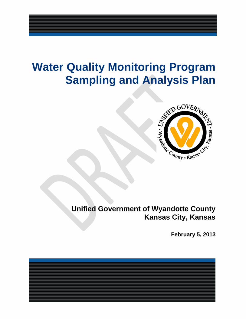
;;j . ~ j ~ ~ ~ ~ ~
0~ __ .,,, --
OlJ11ty • l{a1.\-'='~':,
Water Quality Monitoring Program Sampling and Analysis Plan
Unified Government of Wyandotte County Kansas City, Kansas
February 5, 2013
Water Quality Monitoring Program Sampling and Analysis Plan
prepared for
Unified Government of Wyandotte County Kansas City, Kansas
Unified Government of Wyandotte Co./Kansas City, KS Sampling and Analysis Plan
TABLE OF CONTENTS Page No.
1.0 INTRODUCTION AND OBJECTIVES..........................................................................1-1
2.0 WATER QUALITY MONITORING................................................................................2-1 2.1 SAMPLING LOCATIONS AND PARAMETERS .....................................................................2-1
2.2 SAMPLING SCHEDULE ............................................................................................................2-4
2.3 ROUTINE EVENTS.....................................................................................................................2-4
2.4 WET WEATHER EVENTS.........................................................................................................2-5
2.4.1 WET WEATHER SAMPLING PROTOCOL..............................................................................2-6
3.0 FIELD PROCEDURES AND METHODS......................................................................3-1 3.1 SAMPLING EQUIPMENT ..........................................................................................................3-1
3.2 EQUIPMENT CLEANING ..........................................................................................................3-1
3.3 FIELD DOCUMENTATION .......................................................................................................3-1
3.4 FIELD MEASUREMENTS..........................................................................................................3-2
3.5 SAMPLE HANDLING AND CUSTODY ...................................................................................3-4
3.6 SAMPLE LABELING..................................................................................................................3-5
3.7 SAMPLE DELIVERY..................................................................................................................3-6
3.8 CHAIN-OF-CUSTODY FORMS.................................................................................................3-7
3.9 DATA SUBMITTAL....................................................................................................................3-7
4.0 QUALITY CONTROL...................................................................................................4-1 4.1 FIELD BLANKS ..........................................................................................................................4-1
4.2 FIELD DUPLICATES..................................................................................................................4-1
5.0 PROGRAM SAFETY....................................................................................................5-1 5.1 GENERAL SAFETY PRACTICES .............................................................................................5-1
5.2 HEALTH HAZARDS...................................................................................................................5-1
SAP Draft _020413.docx TOC-3 February 5, 2013
Unified Government of Wyandotte Co./Kansas City, KS Sampling and Analysis Plan
APPENDIX A - FIELD DOCUMENTATION ................................................................................1
LIST OF TABLES
Table No. Page No.
Table 2-1 Sampling Locations ..................................................................................................................2-2
Table 2-2 Analytical and Field Parameters...............................................................................................2-4
Table 3-1 Sampling Equipment List .........................................................................................................3-1
Table 3-2 Summary of Field Measurements.............................................................................................3-3
Table 3-3 Summary of Field Observations ...............................................................................................3-3
Table 3-4 Water Quality Samples and Laboratory Analytical Methods...................................................3-5
LIST OF FIGURES
Figure 2-1 Water Quality Sampling Locations .........................................................................................2-3
* * * * *
SAP Draft _020413.docx TOC-4 February 5, 2013
Unified Government of Wyandotte Co./Kansas City, KS Sampling and Analysis Plan
1.0 INTRODUCTION AND OBJECTIVES
The Unified Government of Wyandotte County/Kansas City, Kansas (UG) is developing an Integrated
(combined sewer and sanitary sewer) Overflow Control Plan (IOCP) as part of a commitment to
protecting water resources in its watersheds and providing compliance with State and federal regulations
governing water quality. This Sampling and Analysis Plan (SAP) was developed to provide practical
assistance in obtaining representative and reliable water quality data in a technically sound, safe and cost-
effective manner.
The SAP is designed to collect data that will be used to assess water quality concerns associated with
CSOs and support the development of the IOCP. The objective is to further characterize CSO impacts on
the receiving waters, namely Jersey Creek, Mattoon Creek, the Kansas River, and the Missouri River, and
inform the decision-making process for determining an appropriate level of CSO control.
The UG’s monitoring program will start in the spring of 2013 and the work will be contracted to
LimnoTech Inc. Sampling and analysis efforts will be conducted in accordance with this SAP, the
associated Quality Assurance Project Plan (LimnoTech, 2013), the Laboratory’s Quality Assurance
Manual, and a Health and Safety Plan (HASP). The Quality Assurance Project Plan (QAPP) and Quality
Assurance Manual include information on responsibilities, sampling procedures, quality control checks,
data management and reporting. The HASP includes information on responsibilities, safe work practices,
hazards and controls, and emergency procedures. Any UG or LimnoTech contractors must operate under
their own HASP.
This SAP is divided into the following sections:
• Introduction and Objectives
• Water Quality Monitoring
• Field Methods and Procedures
• Quality Control
• Program Safety
* * * * *
SAP Draft _020413.docx 1-1 February 5, 2013
Unified Government of Wyandotte Co./Kansas City, KS Sampling and Analysis Plan
2.0 WATER QUALITY MONITORING
This section presents the monitoring locations, parameters, and the schedule for the monitoring program.
2.1 SAMPLING LOCATIONS AND PARAMETERS Ambient stream monitoring will be conducted at up to eleven (11) locations including sites in the Kansas
River, Missouri River, Jersey Creek, Mattoon Creek and Turkey Creek. CSO monitoring will be
conducted at two (2) overflows within UG combined sewer system (CSS). The sampling locations are
listed in Table 2-1 and are depicted on Figure 2-1. These locations were selected to characterize water
quality conditions upstream and downstream of CSO impacts and support the development and
calibration of water quality models. Site accessibility and safety were also considered in location
selection.
Field measurements of water temperature, pH, and dissolved oxygen will be recorded at each monitoring
site using calibrated water quality meters. Concurrent with field measurements, observations will be
made and recorded at each monitoring location related to weather, aesthetic impacts and evidence of
recreational use. Immediately following field measurements at a monitoring site, water samples will be
collected for laboratory analysis. The samples collected at each site will be analyzed for the parameters
shown in Table 2-2. Additional information on field methods and procedures is presented in Section 3 of
this document.
SAP Draft _020413.docx 2-1 February 5, 2013
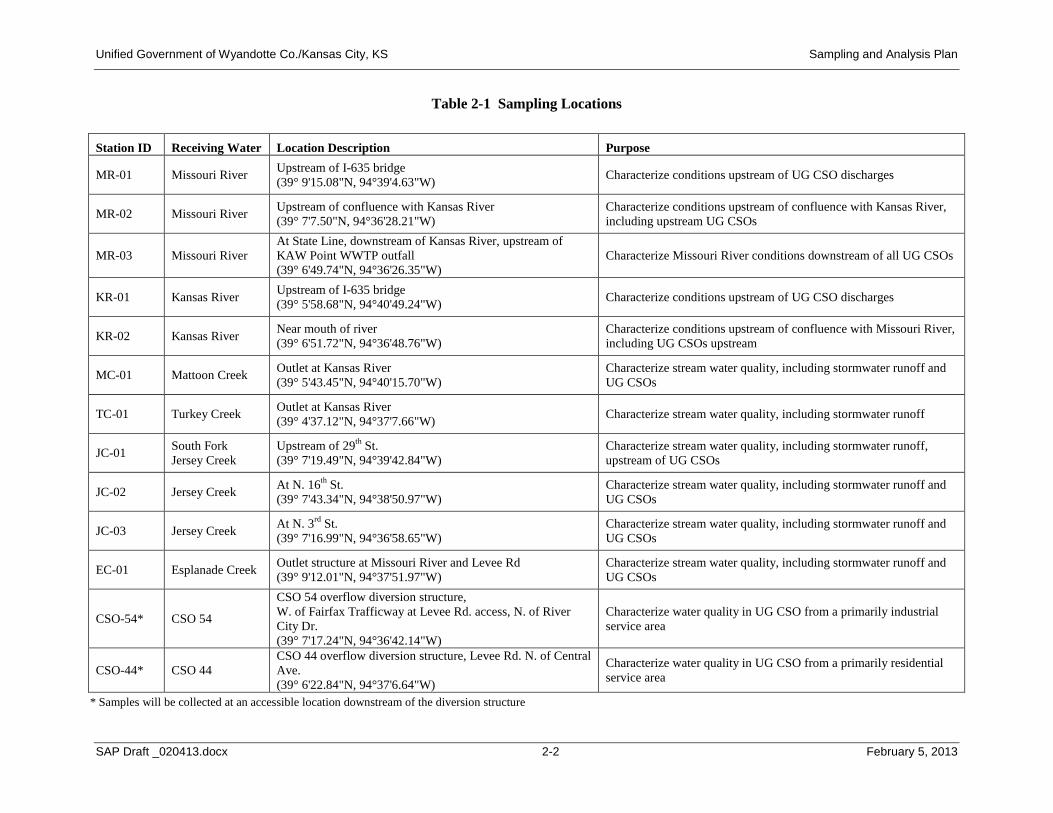
Unified Government of Wyandotte Co./Kansas City, KS Sampling and Analysis Plan
Table 2-1 Sampling Locations
Station ID Receiving Water Location Description Purpose
MR-01 Missouri River Upstream of I-635 bridge (39° 9'15.08"N, 94°39'4.63"W) Characterize conditions upstream of UG CSO discharges
MR-02 Missouri River Upstream of confluence with Kansas River (39° 7'7.50"N, 94°36'28.21"W)
Characterize conditions upstream of confluence with Kansas River, including upstream UG CSOs
MR-03 Missouri River At State Line, downstream of Kansas River, upstream of KAW Point WWTP outfall (39° 6'49.74"N, 94°36'26.35"W)
Characterize Missouri River conditions downstream of all UG CSOs
KR-01 Kansas River Upstream of I-635 bridge (39° 5'58.68"N, 94°40'49.24"W) Characterize conditions upstream of UG CSO discharges
KR-02 Kansas River Near mouth of river (39° 6'51.72"N, 94°36'48.76"W)
Characterize conditions upstream of confluence with Missouri River, including UG CSOs upstream
MC-01 Mattoon Creek Outlet at Kansas River (39° 5'43.45"N, 94°40'15.70"W)
Characterize stream water quality, including stormwater runoff and UG CSOs
TC-01 Turkey Creek Outlet at Kansas River (39° 4'37.12"N, 94°37'7.66"W) Characterize stream water quality, including stormwater runoff
JC-01 South Fork Jersey Creek
Upstream of 29th St. (39° 7'19.49"N, 94°39'42.84"W)
Characterize stream water quality, including stormwater runoff, upstream of UG CSOs
JC-02 Jersey Creek At N. 16th St. (39° 7'43.34"N, 94°38'50.97"W)
Characterize stream water quality, including stormwater runoff and UG CSOs
JC-03 Jersey Creek At N. 3rd St. (39° 7'16.99"N, 94°36'58.65"W)
Characterize stream water quality, including stormwater runoff and UG CSOs
EC-01 Esplanade Creek Outlet structure at Missouri River and Levee Rd (39° 9'12.01"N, 94°37'51.97"W)
Characterize stream water quality, including stormwater runoff and UG CSOs
CSO-54* CSO 54
CSO 54 overflow diversion structure, W. of Fairfax Trafficway at Levee Rd. access, N. of River City Dr. (39° 7'17.24"N, 94°36'42.14"W)
Characterize water quality in UG CSO from a primarily industrial service area
CSO-44* CSO 44 CSO 44 overflow diversion structure, Levee Rd. N. of Central Ave. (39° 6'22.84"N, 94°37'6.64"W)
Characterize water quality in UG CSO from a primarily residential service area
* Samples will be collected at an accessible location downstream of the diversion structure
SAP Draft _020413.docx 2-2 February 5, 2013
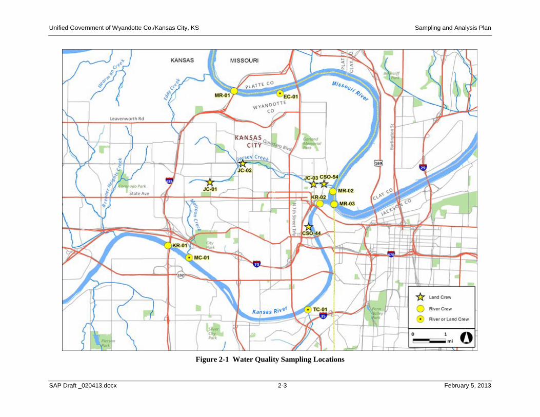
S MISSOURI
and Crew
Ri\o°E!r or Laoo Crew
1 ml 0
Unified Government of Wyandotte Co./Kansas City, KS Sampling and Analysis Plan
Figure 2-1 Water Quality Sampling Locations
SAP Draft _020413.docx 2-3 February 5, 2013
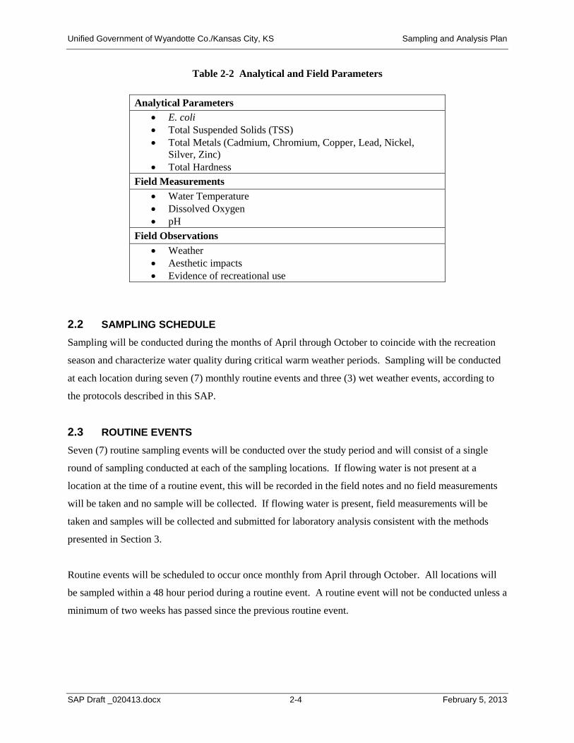
Unified Government of Wyandotte Co./Kansas City, KS Sampling and Analysis Plan
Table 2-2 Analytical and Field Parameters
Analytical Parameters • E. coli • Total Suspended Solids (TSS) • Total Metals (Cadmium, Chromium, Copper, Lead, Nickel,
Silver, Zinc) • Total Hardness
Field Measurements • Water Temperature • Dissolved Oxygen • pH
Field Observations • Weather • Aesthetic impacts • Evidence of recreational use
2.2 SAMPLING SCHEDULE Sampling will be conducted during the months of April through October to coincide with the recreation
season and characterize water quality during critical warm weather periods. Sampling will be conducted
at each location during seven (7) monthly routine events and three (3) wet weather events, according to
the protocols described in this SAP.
2.3 ROUTINE EVENTS Seven (7) routine sampling events will be conducted over the study period and will consist of a single
round of sampling conducted at each of the sampling locations. If flowing water is not present at a
location at the time of a routine event, this will be recorded in the field notes and no field measurements
will be taken and no sample will be collected. If flowing water is present, field measurements will be
taken and samples will be collected and submitted for laboratory analysis consistent with the methods
presented in Section 3.
Routine events will be scheduled to occur once monthly from April through October. All locations will
be sampled within a 48 hour period during a routine event. A routine event will not be conducted unless a
minimum of two weeks has passed since the previous routine event.
SAP Draft _020413.docx 2-4 February 5, 2013
Unified Government of Wyandotte Co./Kansas City, KS Sampling and Analysis Plan
Sampling will be conducted using a two-person crew in a boat for the large river sites. A one or two
person crew will be used for land-based sampling of stream and CSO locations. All sampling will be
performed when safe to do so.
2.4 WET WEATHER EVENTS Three (3) wet weather events will be conducted over the study period. Details of the Wet Weather
Sampling Protocol are presented in the following subsection of this document. Every attempt will be
made to sample storms that meet the criteria used to define a wet weather event, as follows:
• No local precipitation within 72 hours before the event; and,
• A minimum of 0.50 inches of rainfall over a six-hour period.
A wet weather event will be initiated by the LimnoTech Field Manager, or designee, based on a forecast
that the above criteria will be satisfied. The LimnoTech Project Manager will notify the IOCP Program
Manager and UG that a wet weather event is being initiated.
The wet weather criteria will serve as the minimum requirements for initiating a wet weather sampling
event. Local conditions may require these criteria to be modified as the study progresses. Best
professional judgment will be necessary to assess the suitability of a particular wet weather sampling
event.
Sampling intervals are discussed below. These intervals may be adjusted to address each distinct wet
weather event.
Wet Weather CSO Sampling Intervals. At CSO overflow locations three (3) rounds of sampling will be
conducted at each location during the course of a wet weather event. The intent will be to collect the first
sample as close as possible to the initiation of overflow. Collection of the second sample will be targeted
to occur between 2 and 4 hours after the first sample, and collection of the third sample will again be
targeted to occur between 2 and 4 hours after the second sample. It is important to note that not every
CSO will necessarily overflow during a wet weather event and a CSO may not discharge long enough for
collection of three individual samples during a single event. Only active CSOs will be sampled during
each wet weather sampling event. These samples will serve to evaluate first flush conditions as well as
develop event mean concentrations for CSOs.
SAP Draft _020413.docx 2-5 February 5, 2013
Unified Government of Wyandotte Co./Kansas City, KS Sampling and Analysis Plan
Wet Weather Stream Sampling Intervals. At each stream location three (3) rounds of sampling will be
conducted during each wet weather sampling event. The intent will be to collect the first sample as close
as possible to the initiation of precipitation. Collection of the second sample will be targeted to occur
between 6 and 24 hours after the first sample, and collection of the third sample will again be targeted to
occur between 6 and 24 hours after the second sample. It is important to note that precipitation duration
is extremely difficult to predict so adaption of the sampling schedule during an event may be needed.
2.4.1 WET WEATHER SAMPLING PROTOCOL Decisions to initiate and continue sampling for wet weather events are given below.
• LimnoTech will monitor the weather forecasts within the study area on a daily basis.
• Precipitation should cover the majority of the CSS area to be considered as a wet weather event.
Spotty rain events in certain parts of the watershed will not be sampled.
• When precipitation of greater than 0.5 inch is forecasted with greater than 50% probability, and the
CSS has not experienced measureable precipitation in the previous 72 hours, the LimnoTech Field
Manager will notify the sampling team and laboratory to be put on alert. This alert will be considered
“Go” status, unless otherwise notified. The sampling team will begin mobilizing equipment, bottles
and personnel so that they can initiate sampling when precipitation begins.
• The sampling team will confer with the LimnoTech Field Manager to confirm timing for initiation of
sampling and subsequent rounds of sampling. The LimnoTech Field Manager will notify the
analytical laboratory when sampling has been initiated. The sampling team will coordinate with the
analytical laboratory for transfer of samples.
• LimnoTech will continue to monitor the precipitation as the rain event progresses. If the storm
conditions are significantly smaller than forecasted (either in rainfall depth or geographical extent),
the sampling event may be aborted.
• If a wet weather event is aborted, LimnoTech may either direct the sampling team and analytical
laboratory to complete one round of sampling and analysis for use as a routine event, or LimnoTech
may direct the sampling team to discard samples and the laboratory to cancel analysis of samples
received.
* * * * *
SAP Draft _020413.docx 2-6 February 5, 2013
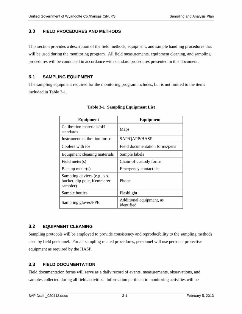
Unified Government of Wyandotte Co./Kansas City, KS Sampling and Analysis Plan
3.0 FIELD PROCEDURES AND METHODS
This section provides a description of the field methods, equipment, and sample handling procedures that
will be used during the monitoring program. All field measurements, equipment cleaning, and sampling
procedures will be conducted in accordance with standard procedures presented in this document.
3.1 SAMPLING EQUIPMENT The sampling equipment required for the monitoring program includes, but is not limited to the items
included in Table 3-1.
Table 3-1 Sampling Equipment List
Equipment Equipment Calibration materials/pH standards Maps
Instrument calibration forms SAP/QAPP/HASP
Coolers with ice Field documentation forms/pens
Equipment cleaning materials Sample labels Field meter(s) Chain-of-custody forms Backup meter(s) Emergency contact list Sampling devices (e.g., s.s. bucket, dip pole, Kemmerer sampler)
Phone
Sample bottles Flashlight
Sampling gloves/PPE Additional equipment, as identified
3.2 EQUIPMENT CLEANING Sampling protocols will be employed to provide consistency and reproducibility to the sampling methods
used by field personnel. For all sampling related procedures, personnel will use personal protective
equipment as required by the HASP.
3.3 FIELD DOCUMENTATION Field documentation forms will serve as a daily record of events, measurements, observations, and
samples collected during all field activities. Information pertinent to monitoring activities will be
SAP Draft _020413.docx 3-1 February 5, 2013
Unified Government of Wyandotte Co./Kansas City, KS Sampling and Analysis Plan
recorded on the field documentation forms and stored sequentially in a field log book, preferably a three-
ring binder. Entries on the field documentation forms will include:
• Date and time of sampling
• Names of field crew
• Weather conditions (e.g., air temperature, cloud cover, precipitation or snowmelt)
• Sampling location ID
• Location of measurements and sample collection
• Water quality meter identification number
• Field measurement results
• Sampling equipment used
• Number of samples collected
• Sample identification number
• Field observations and details related to analysis or integrity of samples (e.g., weather conditions,
noticeable odors, colors, stream flow conditions, etc.)
An example of a field documentation form is provided in Appendix A. A copy of this form, or similar
form, should be filled out each time sampling and/or field measurements are conducted at a sampling
location. In the event of wet weather, field forms on waterproof paper and a “write in the rain” pen may
be used to record field observations and field measurement data. Information recorded in a field book
should be transferred to separate field documentation forms as soon as possible following the completion
of a sampling round.
3.4 FIELD MEASUREMENTS Field measurements of the water quality parameters listed in Table 3-2 will be taken at the sample
collection point depth, where possible, at each sampling location using a water quality meter, as follows.
• For the Kansas River and Missouri River sampling locations, field measurements will be taken from
mid-depth at three (3) stations across the river including, off the left bank, in the center channel and
off the right bank, looking upstream.
• For all other stream sampling locations, field measurements will be taken at mid-depth in the center
of the stream, if possible. Otherwise, measurements should be taken from the bank at a
representative, well-mixed location as close to the center of the stream as possible.
SAP Draft _020413.docx 3-2 February 5, 2013
Unified Government of Wyandotte Co./Kansas City, KS Sampling and Analysis Plan
• For the CSO sampling locations, field measurements will be taken in the flowing water in the
structure, if possible. Otherwise, field measurements may be recorded from the collected water
immediately after collection.
Calibration of water quality meters should be performed at the beginning of each monitoring day prior to
initiating any measurements and checked again at the end of each day. Calibration results will be
recorded on a meter calibration and maintenance log maintained in the field log book.
Table 3-2 Summary of Field Measurements
Parameter Units Location of Measurement Method
Temperature deg. Celsius
Mid-channel in streams or in flow of CSO, where possible, otherwise measure collected water Left, center and right channels at mid-depth for Kansas and Missouri River locations
Water quality meter (YSI, Hydrolab or similar other
brand) pH std. units Dissolved Oxygen
mg/l
Concurrent with field measurements, observations will be made at each monitoring location related to
weather, aesthetic impacts and evidence of recreational use. These observations will be documented on a
field documentation form. Table 3-3 summarizes the types of observations that should be recorded at
each location. The field crew is encouraged to take pictures, log them on a field documentation form, and
include them in the field log book with appropriate documentation (date, time, location and description of
noteworthy items).
Table 3-3 Summary of Field Observations
Observation Type Potential Descriptors Floating Debris Logs, woody debris, oil sheen, type of trash (e.g. sanitary products, beverage
containers, etc.) Submerged Debris Tires, bottles, trash, etc. or not able to see bottom
Algal Growth None, light, medium, heavy, submerged or emergent Odor Septic, etc.
Recreational Use Primary (Swimming) or Secondary (wading, boating, canoeing, kayaking, fishing, etc.)
SAP Draft _020413.docx 3-3 February 5, 2013
Unified Government of Wyandotte Co./Kansas City, KS Sampling and Analysis Plan
3.5 SAMPLE HANDLING AND CUSTODY Samples for laboratory analysis will be collected at all sampling locations, as described below.
CSO locations:
• CSO samples may be collected using one of three methods:
− By lowering a clean stainless steel bucket into the water and then pouring from the bucket to
clean sample containers.
− By dipping a clean container attached to a pole into the water, pouring the sample into a clean
stainless steel bucket until enough sample volume has been collected, and then pouring from the
bucket into the clean sample containers.
− By collecting the sample directly into the sample containers. The direct method should be used
with caution for the collection of samples where sample bottles already contain preservatives.
Stream locations:
• For the Kansas River and Missouri River sampling locations, samples will be collected from a boat at
three (3) stations across the river including, off the left bank, in the center channel and off the right
bank, looking upstream. The samples will be collected at mid-depth using a Kemmerer (or
equivalent) sampler.
• For all other stream sampling locations, samples will be collected at mid-depth in the center of the
stream, if possible. Otherwise, samples should be taken from the bank at a representative, well-mixed
location as close to the center of the stream as possible. Samples may be collected using one of three
methods:
− By lowering a clean stainless steel bucket into the water and then pouring from the bucket to
clean sample containers.
− By dipping a clean container attached to a pole into the water, pouring the sample into a clean
stainless steel bucket until enough sample volume has been collected, and then pouring from the
bucket into the clean sample containers.
− By collecting the sample directly into the sample containers. The direct method should be used
with caution for the collection of samples where sample bottles already contain preservatives.
SAP Draft _020413.docx 3-4 February 5, 2013
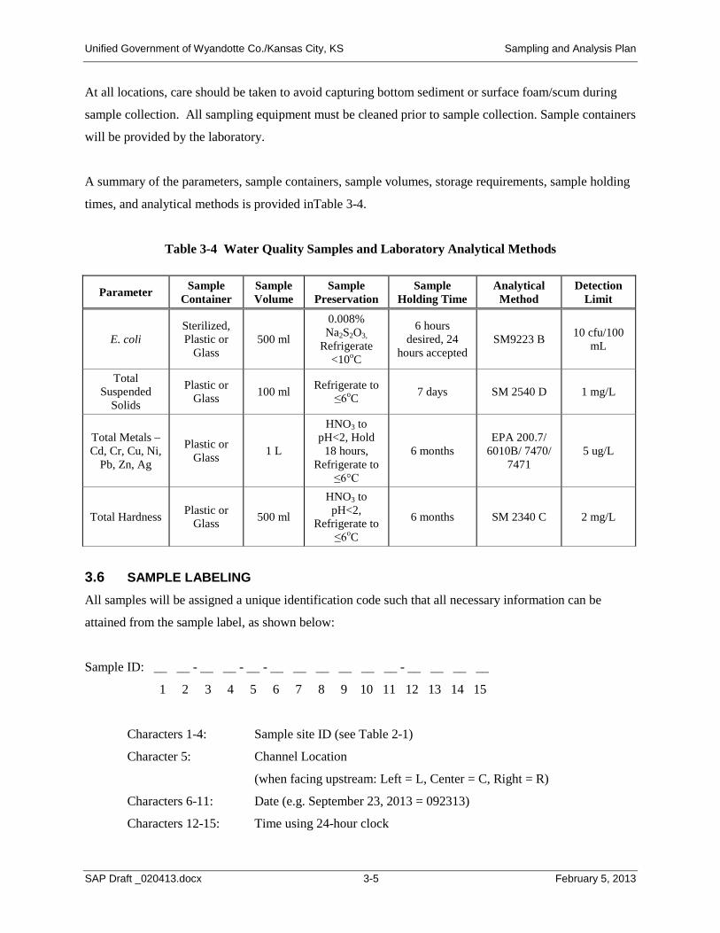
Unified Government of Wyandotte Co./Kansas City, KS Sampling and Analysis Plan
At all locations, care should be taken to avoid capturing bottom sediment or surface foam/scum during
sample collection. All sampling equipment must be cleaned prior to sample collection. Sample containers
will be provided by the laboratory.
A summary of the parameters, sample containers, sample volumes, storage requirements, sample holding
times, and analytical methods is provided inTable 3-4.
Table 3-4 Water Quality Samples and Laboratory Analytical Methods
Parameter Sample Container
Sample Volume
Sample Preservation
Sample Holding Time
Analytical Method
Detection Limit
E. coli Sterilized, Plastic or
Glass 500 ml
0.008% Na2S2O3,
Refrigerate <10oC
6 hours desired, 24
hours accepted SM9223 B 10 cfu/100
mL
Total Suspended
Solids
Plastic or Glass 100 ml Refrigerate to
≤6oC 7 days SM 2540 D 1 mg/L
HNO3 to Total Metals – Cd, Cr, Cu, Ni,
Pb, Zn, Ag
Plastic or Glass 1 L
pH<2, Hold 18 hours,
Refrigerate to 6 months
EPA 200.7/ 6010B/ 7470/
7471 5 ug/L
≤6°C
Total Hardness Plastic or Glass 500 ml
HNO3 to pH<2,
Refrigerate to ≤6oC
6 months SM 2340 C 2 mg/L
3.6 SAMPLE LABELING All samples will be assigned a unique identification code such that all necessary information can be
attained from the sample label, as shown below:
Sample ID: __ __ - __ __ - __ - __ __ __ __ __ __ - __ __ __ __
1 2 3 4 5 6 7 8 9 10 11 12 13 14 15
Characters 1-4: Sample site ID (see Table 2-1)
Character 5: Channel Location
(when facing upstream: Left = L, Center = C, Right = R)
Characters 6-11: Date (e.g. September 23, 2013 = 092313)
Characters 12-15: Time using 24-hour clock
SAP Draft _020413.docx 3-5 February 5, 2013
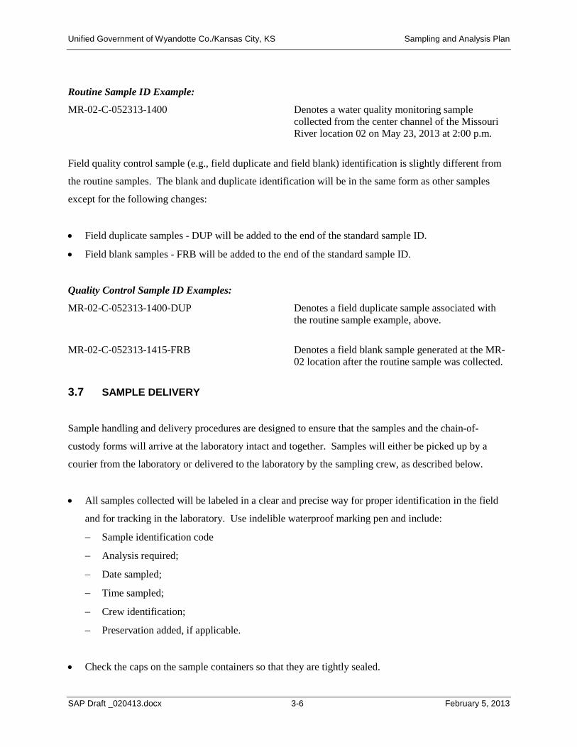
Unified Government of Wyandotte Co./Kansas City, KS Sampling and Analysis Plan
Routine Sample ID Example:
MR-02-C-052313-1400 Denotes a water quality monitoring sample collected from the center channel of the Missouri River location 02 on May 23, 2013 at 2:00 p.m.
Field quality control sample (e.g., field duplicate and field blank) identification is slightly different from
the routine samples. The blank and duplicate identification will be in the same form as other samples
except for the following changes:
• Field duplicate samples - DUP will be added to the end of the standard sample ID.
• Field blank samples - FRB will be added to the end of the standard sample ID.
Quality Control Sample ID Examples:
MR-02-C-052313-1400-DUP Denotes a field duplicate sample associated with the routine sample example, above.
MR-02-C-052313-1415-FRB Denotes a field blank sample generated at the MR-02 location after the routine sample was collected.
3.7 SAMPLE DELIVERY
Sample handling and delivery procedures are designed to ensure that the samples and the chain-of-
custody forms will arrive at the laboratory intact and together. Samples will either be picked up by a
courier from the laboratory or delivered to the laboratory by the sampling crew, as described below.
• All samples collected will be labeled in a clear and precise way for proper identification in the field
and for tracking in the laboratory. Use indelible waterproof marking pen and include:
− Sample identification code
− Analysis required;
− Date sampled;
− Time sampled;
− Crew identification;
− Preservation added, if applicable.
• Check the caps on the sample containers so that they are tightly sealed.
SAP Draft _020413.docx 3-6 February 5, 2013
Unified Government of Wyandotte Co./Kansas City, KS Sampling and Analysis Plan
• Cover the sample container label and cap with clear packing tape to secure the label and cap onto the
container, if necessary.
3.8 CHAIN-OF-CUSTODY FORMS Completed chain-of-custody forms will be required for all samples to be analyzed. Chain-of-custody
(COC) forms will be initiated by the sampling crews in the field during the sampling events. The chain-
of-custody form will contain for each sample, a unique identification number, sample date and time,
sample description, sample type, sample preservation, and analyses required. The samples and signed
chain-of-custody form will remain in the possession of the sampling crew until the samples are
relinquished to the control of others (i.e., laboratory staff or delivery personnel). A copy will be retained
for field documentation.
3.9 DATA SUBMITTAL All generated documentation and data (field notes, field forms, instrument calibration sheets, field data,
photos, COCs) will be reviewed for accuracy and completeness by the field crews and sent to the
LimnoTech Field Manager after each monitoring event. Following review by the Field Manager these
items will be included in the project files.
* * * * *
SAP Draft _020413.docx 3-7 February 5, 2013
Unified Government of Wyandotte Co./Kansas City, KS Sampling and Analysis Plan
4.0 QUALITY CONTROL
The monitoring data that will be collected is intended to meet the quality assurance objectives presented
in the Quality Assurance Project Plan (QAPP). Data quality will be measured in terms of accuracy,
precision, completeness, representativeness, comparability, and the required detection limits for the
analytical methods. Each of these data quality indicators is defined in the QAPP. Quality Control
samples will be collected in the field to support the assessment of data quality. This section describes the
type and frequency of Quality Control samples.
4.1 FIELD BLANKS Field accuracy will be assessed through the use of field (or equipment) blanks. Field blanks are used to
evaluate the potential for sample contamination resulting from sampling equipment, supplies or activities.
In order for the accuracy assessment to be relevant, all appropriate protocols concerning sample
collection, handling, preservation, and hold times must be maintained. Field blanks should be collected
after the sampling equipment has been cleaned in accordance with appropriate specified cleaning
procedures. Field blanks will consist of a reagent grade deionized water rinse of sampling equipment that
is collected into separate sample containers. The field blank results should exhibit levels below detection
for all parameters.
Field blanks will be collected at a frequency of 5% or a minimum of one blank during each sampling
event.
4.2 FIELD DUPLICATES Duplicate or replicate samples will be taken for a portion of the samples to assess field precision.
Precision is a measure of the agreement between two or more measurements. A field duplicate is defined
as a sample produced when a single sample is split into two or more aliquots immediately after the sample
is collected. Each aliquot is placed into a separate container and analyzed separately. The laboratory
analysis should result in comparable results for the original sample and the duplicate for the site.
Field duplicates will be collected at a frequency of 10%.
* * * * *
SAP Draft _020413.docx 4-1 February 5, 2013
Unified Government of Wyandotte Co./Kansas City, KS Sampling and Analysis Plan
5.0 PROGRAM SAFETY
Sampling conditions will vary greatly and are often complicated by wet weather and darkness. The
element of danger is accentuated if personnel are unfamiliar with their surroundings and/or procedures.
Consequently, staff must be properly trained in both safety and monitoring procedures. Sampling and
analysis efforts will be conducted in accordance with a Health and Safety Plan (HASP). The HASP will
include information on responsibilities, safe work practices, hazards and controls, and emergency
procedures. Any UG contractors must operate under their own HASP.
With stream and CSO monitoring, common sense is essential. Hazards that field staff may face during
wet weather include high stream conditions and slippery footing. With surfaces being wet and slippery,
special care must be taken when boating, walking and working around bridges and stream banks. Where
sampling from steep stream banks and stream conditions are high and fast, land-based field staff should
wear a safety belt or harness and be appropriately tethered. Additionally, under these conditions, field
staff must wear an approved floatation device. Boat-based field staff must be experienced in boating
operations and be on the look-out for and avoid other river traffic and floating, submerged and overhead
obstructions. Boat-based staff must always wear an approved floatation device.
5.1 GENERAL SAFETY PRACTICES
• Field crews should inform others of sampling schedules and expected itineraries.
• Sampling should not be carried out in weather that is considered by the field crew member to be
hazardous to the well-being of the field staff and/or equipment.
• Field staff are required to wear approved floatation devices and be tethered if conditions warrant.
• First aid kits will be issued to all field crews.
• Each field crew will have a cellular phone and will have been instructed on emergency procedures
and phone numbers.
• Each field crew will have appropriate lights, markers, etc. to be able to perform their work safely
under poor visibility/nightfall.
• Each field crew will have the appropriate road safety equipment as required.
5.2 HEALTH HAZARDS Disease causing bacteria, viruses, and parasites are often present in sewers and receiving streams.
Therefore, proper hygiene methods must be followed. Wash hands before eating or smoking. Personal
SAP Draft _020413.docx 5-1 February 5, 2013
Unified Government of Wyandotte Co./Kansas City, KS Sampling and Analysis Plan
protective equipment must be used as specified in the HASP, specifically the use of latex gloves when
collecting samples. Workers should avoid touching their eyes to prevent an inflammation. Cuts and
abrasions of the skin should be covered by bandages or gloves to minimize the chance of infection by
organisms.
* * * * *
SAP Draft _020413.docx 5-2 February 5, 2013
APPENDIX A Field Documentation
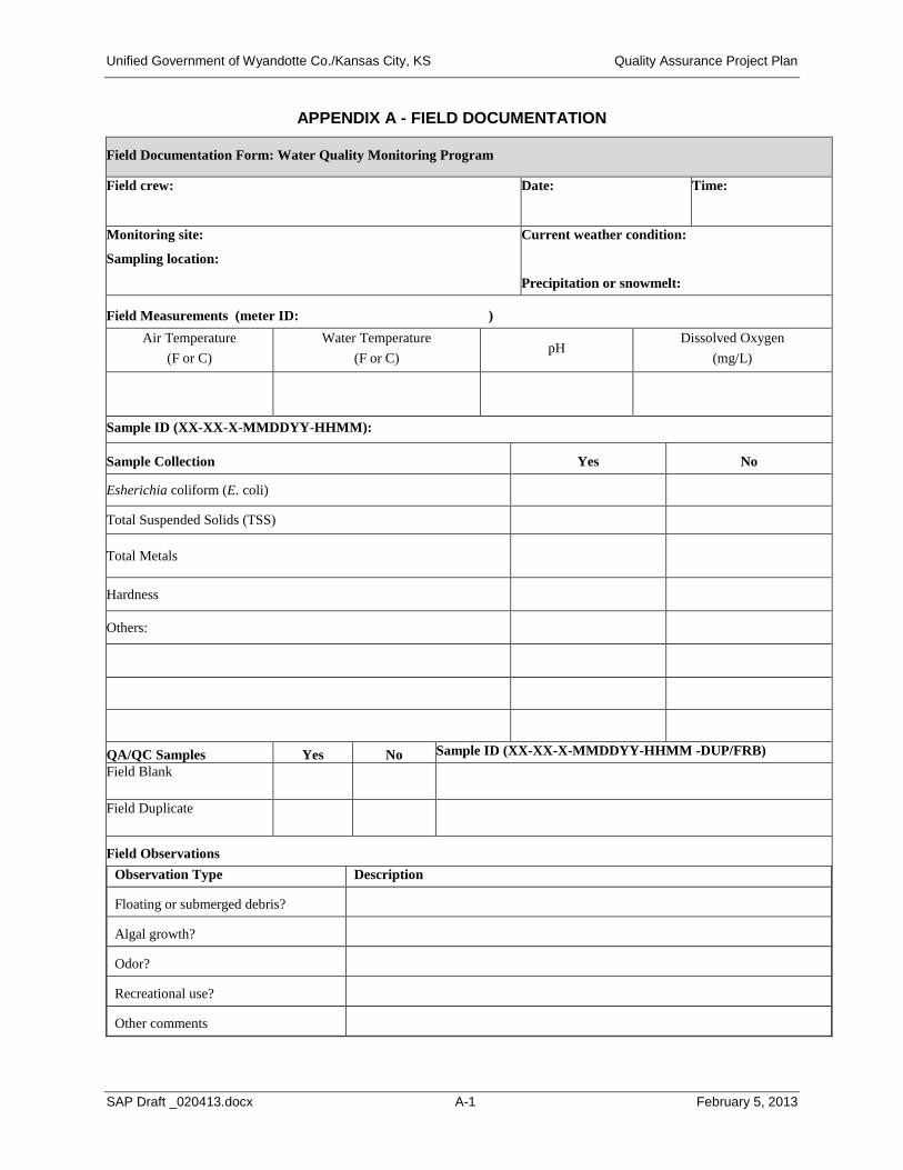
Unified Government of Wyandotte Co./Kansas City, KS Quality Assurance Project Plan
APPENDIX A - FIELD DOCUMENTATION
Field Documentation Form: Water Quality Monitoring Program
Field crew: Date: Time:
Monitoring site:
Sampling location:
Current weather condition:
Precipitation or snowmelt:
Field Measurements (meter ID: ) Air Temperature
(F or C) Water Temperature
(F or C) pH
Dissolved Oxygen (mg/L)
Sample ID (XX-XX-X-MMDDYY-HHMM):
Sample Collection Yes No
Esherichia coliform (E. coli)
Total Suspended Solids (TSS)
Total Metals
Hardness
Others:
QA/QC Samples Yes No Sample ID (XX-XX-X-MMDDYY-HHMM -DUP/FRB) Field Blank
Field Duplicate
Field Observations Observation Type Description
Floating or submerged debris?
Algal growth?
Odor?
Recreational use?
Other comments
SAP Draft _020413.docx A-1 February 5, 2013
Unified Government of Wyandotte Co./Kansas City, KS Quality Assurance Project Plan
CONTACT INFORMATION
Name Organization Office Phone Cell Phone
TBD UG TBD TBD
TBD UG Program Management TBD TBD
Hans Holmberg LimnoTech Project Manager 715-808-0182 651-269-4526
Bob Betz LimnoTech Field Manager 734-332-1200 734-834-8817
TBD Sampling Contractor Project Manager TBD TBD
TBD Sampling Contractor Sampling Team TBD TBD
TBD Sampling Contractor Sampling Team TBD TBD
TBD Analytical Laboratory Project Manager TBD TBD
TBD Analytical Laboratory Sampling
Coordinator TBD TBD
SAP Draft _020413.docx A-2 February 5, 2013
Related Documents