1 INSTALLATION Notes for Generac Air-Cooled Generators Date of Publication: November 1, 2015 © Better Power, Inc., 2015 DISCLAIMER: Only Generac’s official documents for the correct model and serial number of the equipment you are installing should be relied upon. These technical notes are intended to be helpful as a secondary source when you are out in the field.

Welcome message from author
This document is posted to help you gain knowledge. Please leave a comment to let me know what you think about it! Share it to your friends and learn new things together.
Transcript
1
INSTALLATION
Notes for Generac
Air-Cooled Generators Date of Publication: November 1, 2015
© Better Power, Inc., 2015
DISCLAIMER: Only Generac’s official documents for the correct model and serial number of the equipment you are installing should be relied upon. These technical notes are intended to be helpful as a secondary
source when you are out in the field.
2
Table of Contents: Page Number
Permits & Applications 3
Generac Equipment and Accessories 4
Pick Up and Delivery 7
Site Selection and Preparation 8
Fuel Requirements & Pipe Sizing 20
Transfer Switches 32
Basics of How the System Works 34
How to Wire Switches 40
How to Wire the Genset 50
Activation 63
Initial System Tests 67 Loadshedding/SMM Smart Management Modules 73 Smart AC Modules 80
Load Shedding RTSY/T/W-R/P/C, RTSB, & I 81 Prolonged Outages 88
Accessories and Installations Cold Weather Kit 89
MobileLink 90 Local Remote Monitor (Basic) 92
Utility Voltage Monitor Timer (Brown Out) 94 Warning Stickers 96
Bad Installs 97
3
Do NOT modify any equipment.
Do NOT install anything that is not to code.
Any $$ you think you will save on your install by modifying equipment, NOT following the recommended installation procedures, or going against local code, may be a safety issue for your customer, may void
warranties, and may not pass required inspections.
A Generator installation should be a very easy job. Just follow the manufacturer’s instructions, local
requirements, and you should have no problems.
Read ALL Manuals and Install Guides before attempting an install.
Permits and Applications
The Local Code Office has the final say on your install.
All Towns have different requirements. Check with the local code office before submitting a final quote
to your customer.
Brighton and Perinton are two of the more restrictive towns in our area.
Attached are examples of permit for the Town of Perinton and, if you have a NatGas installation
examples of the required RG&E Forms. NYSEG & Other Utilities may have different requirements.
Elevated Pressure Commitment Letter (RG&E) – Residential You probably will not need this
because Generac Evolution Series Air-cooled generators can run on 3.5” to 5” Water Column
Natural Gas Appliance Inventory (RG&E) – Residential Generator Installation This should be filled
out for all NatGas installations
RG&E is looking to see that the total BTU requirements for all appliances and the generator don’t exceed
350,000 BTU.
If exceeded, they may have to increase the pressure to the residence. There is a cost for that. It’s
usually between $150 - $350.
The Town may also ask for things like - Certificates of Liability & Worker’s Comp Site drawing showing
generator placement, nameplate and spec sheet information.
4
Equipment
Generators:
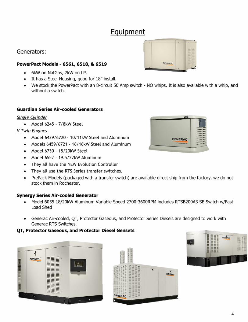
PowerPact Models - 6561, 6518, & 6519
6kW on NatGas, 7kW on LP.
It has a Steel Housing, good for 18” install.
We stock the PowerPact with an 8-circuit 50 Amp switch - NO whips. It is also available with a whip, and
without a switch.
Guardian Series Air-cooled Generators
Single Cylinder
Model 6245 - 7/8kW Steel
V Twin Engines
Model 6439/6720 - 10/11kW Steel and Aluminum
Models 6459/6721 - 16/16kW Steel and Aluminum
Model 6730 - 18/20kW Steel
Model 6552 – 19.5/22kW Aluminum
They all have the NEW Evolution Controller
They all use the RTS Series transfer switches.
PrePack Models (packaged with a transfer switch) are available direct ship from the factory, we do not
stock them in Rochester.
Synergy Series Air-cooled Generator
Model 6055 18/20kW Aluminum Variable Speed 2700-3600RPM includes RTSB200A3 SE Switch w/Fast
Load Shed
Generac Air-cooled, QT, Protector Gaseous, and Protector Series Diesels are designed to work with
Generac RTS Switches.
QT, Protector Gaseous, and Protector Diesel Gensets
5
Transfer Switches
The Whole-House Transfer Switch amperage must be equal to or greater than the generator output or service amperage, whichever is greater.
Air-cooled Generators 6 to 22kW will put out 25 to 91.6 Amps.
Generac’s are smart generators with dumb switches.
That means all the line sensing is done on the generator control board; the generator tells the switch when to transfer power.
On other brands, the switch has the brains and all the generator does is turn on or off. If you absolutely have to use another switch, there is a super-secret code to punch into the controller
that will let the generator run on a 2- wire start, but it probably voids the warranty.
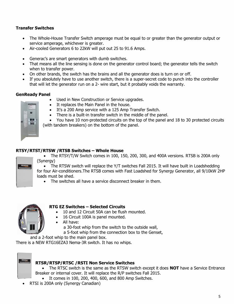
GenReady Panel Used in New Construction or Service upgrades.
It replaces the Main Panel in the house. It's a 200 Amp service with a 125 Amp Transfer Switch.
There is a built-in transfer switch in the middle of the panel.
You have 10 non-protected circuits on the top of the panel and 18 to 30 protected circuits (with tandem breakers) on the bottom of the panel.
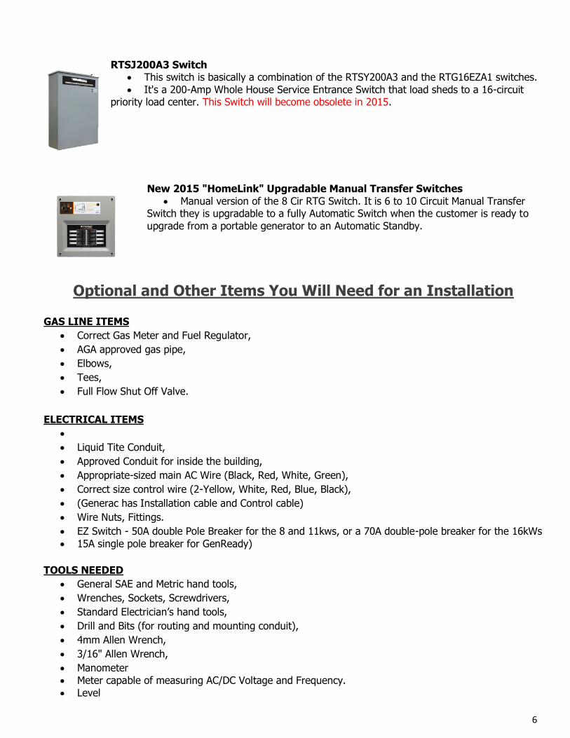
RTSY/RTST/RTSW /RTSB Switches – Whole House
The RTSY/T/W Switch comes in 100, 150, 200, 300, and 400A versions. RTSB is 200A only (Synergy)
The RTSW switch will replace the Y/T switches Fall 2015. It will have built in Loadshedding for four Air-conditioners.The RTSB comes with Fast Loadshed for Synergy Generator, all 9/10kW 2HP
loads must be shed. The switches all have a service disconnect breaker in them.
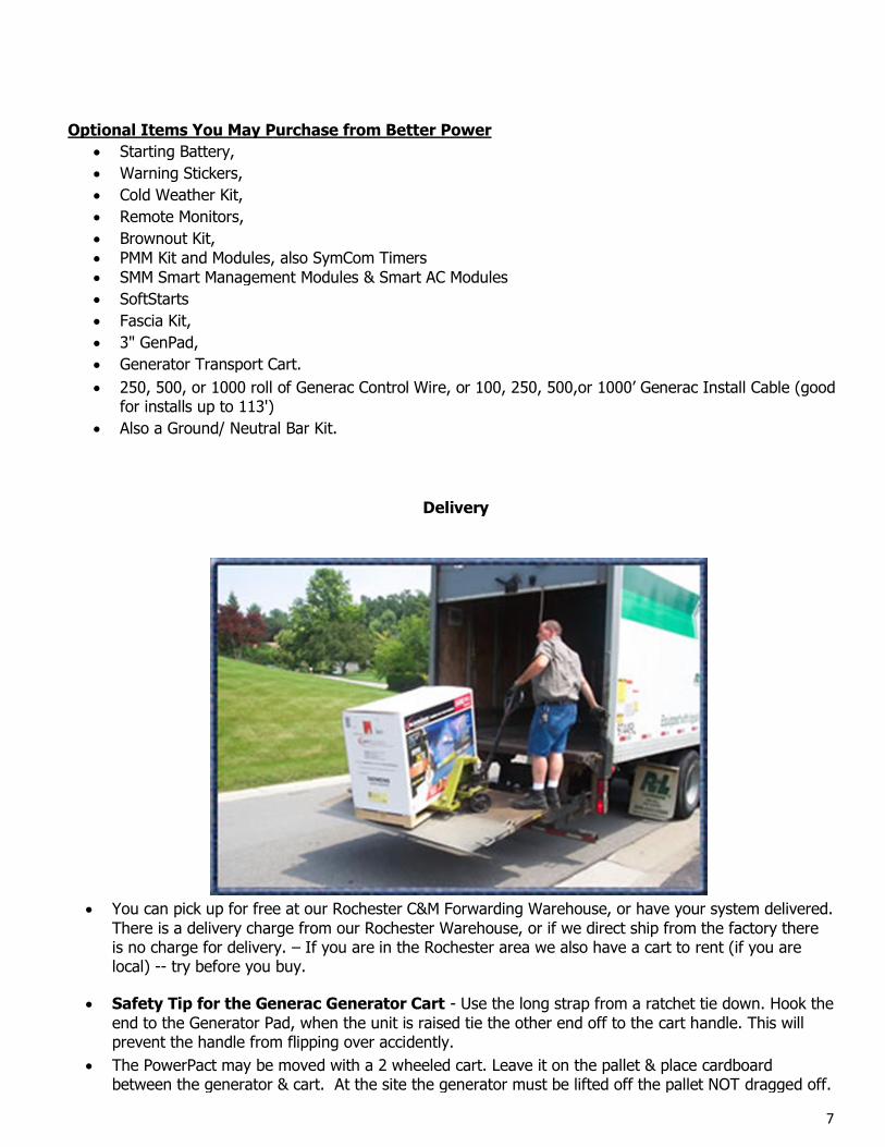
RTG EZ Switches – Selected Circuits
10 and 12 Circuit 50A can be flush mounted. 16 Circuit 100A is panel mounted.
All have:
a 30-foot whip from the switch to the outside wall, a 5-foot whip from the connection box to the Genset,
and a 2-foot whip to the main panel box.
There is a NEW RTG16EZA3 Nema-3R switch. It has no whips.
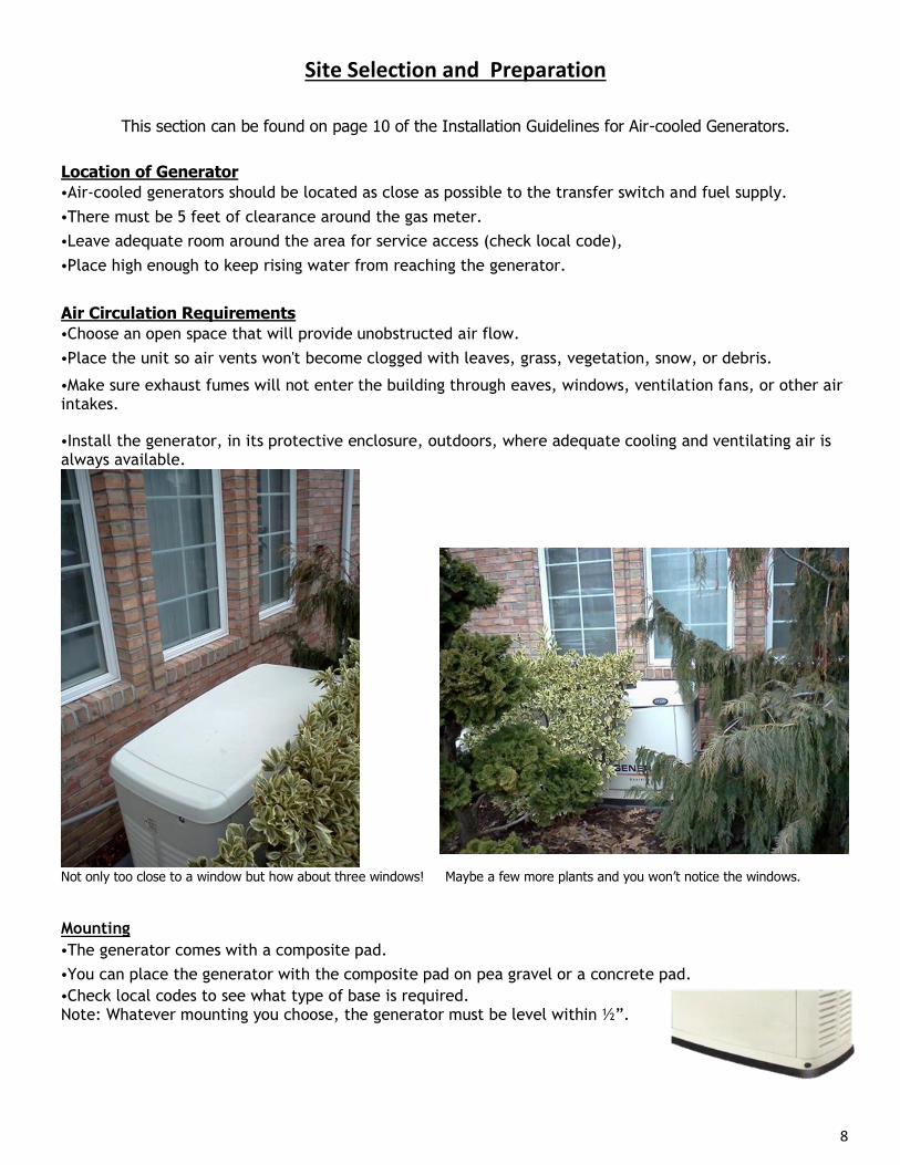
RTSR/RTSP/RTSC /RSTI Non Service Switches
The RTSC switch is the same as the RTSW switch except it does NOT have a Service Entrance Breaker or internal cover. It will replace the R/P switches Fall 2015.
It comes in 100, 200, 400, 600, and 800 Amp Switches. RTSI is 200A only (Synergy Canadian)
6
RTSJ200A3 Switch This switch is basically a combination of the RTSY200A3 and the RTG16EZA1 switches.
It's a 200-Amp Whole House Service Entrance Switch that load sheds to a 16-circuit priority load center. This Switch will become obsolete in 2015.
New 2015 "HomeLink" Upgradable Manual Transfer Switches
Manual version of the 8 Cir RTG Switch. It is 6 to 10 Circuit Manual Transfer Switch they is upgradable to a fully Automatic Switch when the customer is ready to
upgrade from a portable generator to an Automatic Standby.
Optional and Other Items You Will Need for an Installation
GAS LINE ITEMS
Correct Gas Meter and Fuel Regulator,
AGA approved gas pipe,
Elbows,
Tees,
Full Flow Shut Off Valve.
ELECTRICAL ITEMS
Liquid Tite Conduit,
Approved Conduit for inside the building,
Appropriate-sized main AC Wire (Black, Red, White, Green),
Correct size control wire (2-Yellow, White, Red, Blue, Black),
(Generac has Installation cable and Control cable)
Wire Nuts, Fittings.
EZ Switch - 50A double Pole Breaker for the 8 and 11kws, or a 70A double-pole breaker for the 16kWs
15A single pole breaker for GenReady)
TOOLS NEEDED
General SAE and Metric hand tools,
Wrenches, Sockets, Screwdrivers,
Standard Electrician’s hand tools,
Drill and Bits (for routing and mounting conduit),
4mm Allen Wrench,
3/16" Allen Wrench,
Manometer
Meter capable of measuring AC/DC Voltage and Frequency.
Level
7
Optional Items You May Purchase from Better Power
Starting Battery,
Warning Stickers,
Cold Weather Kit,
Remote Monitors,
Brownout Kit,
PMM Kit and Modules, also SymCom Timers
SMM Smart Management Modules & Smart AC Modules
SoftStarts
Fascia Kit,
3" GenPad,
Generator Transport Cart.
250, 500, or 1000 roll of Generac Control Wire, or 100, 250, 500,or 1000’ Generac Install Cable (good for installs up to 113')
Also a Ground/ Neutral Bar Kit.
Delivery
You can pick up for free at our Rochester C&M Forwarding Warehouse, or have your system delivered.
There is a delivery charge from our Rochester Warehouse, or if we direct ship from the factory there is no charge for delivery. – If you are in the Rochester area we also have a cart to rent (if you are local) -- try before you buy.
Safety Tip for the Generac Generator Cart - Use the long strap from a ratchet tie down. Hook the
end to the Generator Pad, when the unit is raised tie the other end off to the cart handle. This will prevent the handle from flipping over accidently.
The PowerPact may be moved with a 2 wheeled cart. Leave it on the pallet & place cardboard between the generator & cart. At the site the generator must be lifted off the pallet NOT dragged off.
8
Site Selection and Preparation
This section can be found on page 10 of the Installation Guidelines for Air-cooled Generators.
Location of Generator
•Air-cooled generators should be located as close as possible to the transfer switch and fuel supply.
•There must be 5 feet of clearance around the gas meter.
•Leave adequate room around the area for service access (check local code),
•Place high enough to keep rising water from reaching the generator.
Air Circulation Requirements
•Choose an open space that will provide unobstructed air flow.
•Place the unit so air vents won't become clogged with leaves, grass, vegetation, snow, or debris.
•Make sure exhaust fumes will not enter the building through eaves, windows, ventilation fans, or other air intakes.
•Install the generator, in its protective enclosure, outdoors, where adequate cooling and ventilating air is always available.
Not only too close to a window but how about three windows! Maybe a few more plants and you won’t notice the windows.
Mounting
•The generator comes with a composite pad.
•You can place the generator with the composite pad on pea gravel or a concrete pad.
•Check local codes to see what type of base is required. Note: Whatever mounting you choose, the generator must be level within ½”.
9
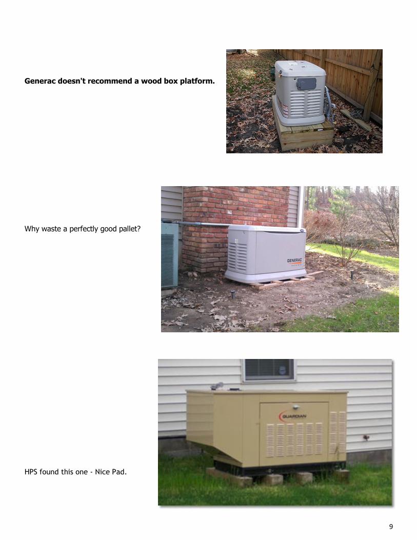
Generac doesn't recommend a wood box platform.
Why waste a perfectly good pallet?
HPS found this one - Nice Pad.
10
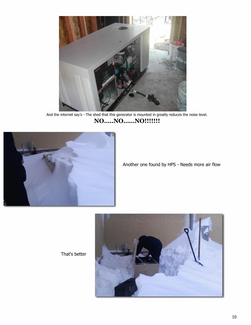
And the internet say’s - The shed that this generator is mounted in greatly reduces the noise level.
NO…..NO……NO!!!!!!!
Another one found by HPS - Needs more air flow
That's better
11
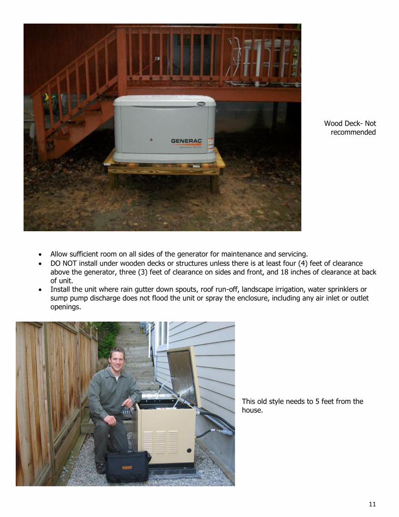
Wood Deck- Not
recommended
Allow sufficient room on all sides of the generator for maintenance and servicing.
DO NOT install under wooden decks or structures unless there is at least four (4) feet of clearance
above the generator, three (3) feet of clearance on sides and front, and 18 inches of clearance at back of unit.
Install the unit where rain gutter down spouts, roof run-off, landscape irrigation, water sprinklers or
sump pump discharge does not flood the unit or spray the enclosure, including any air inlet or outlet
openings.
This old style needs to 5 feet from the
house.
12
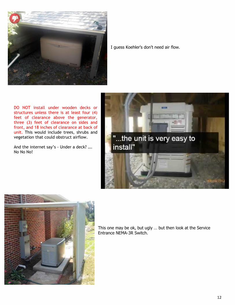
I guess Koehler's don't need air flow.
DO NOT install under wooden decks or structures unless there is at least four (4) feet of clearance above the generator, three (3) feet of clearance on sides and front, and 18 inches of clearance at back of unit. This would include trees, shrubs and vegetation that could obstruct airflow. And the internet say’s - Under a deck? …. No No No!
This one may be ok, but ugly … but then look at the Service Entrance NEMA-3R Switch.
13
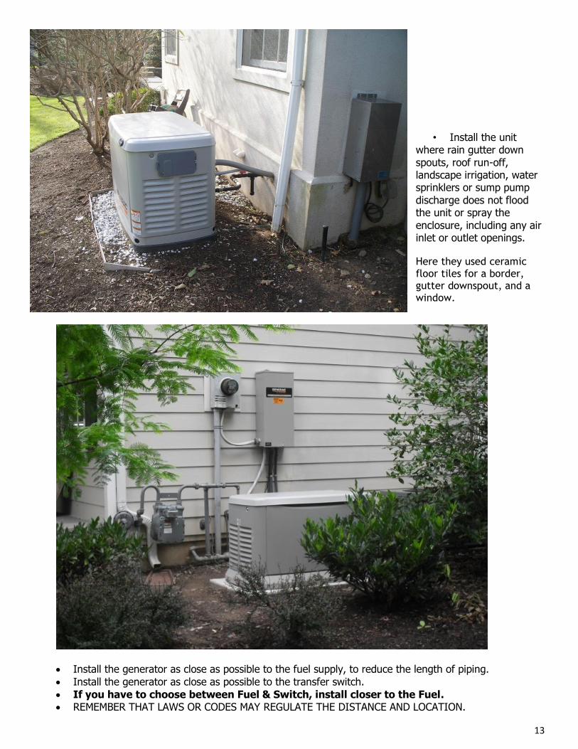
• Install the unit where rain gutter down
spouts, roof run-off, landscape irrigation, water sprinklers or sump pump
discharge does not flood the unit or spray the
enclosure, including any air inlet or outlet openings. Here they used ceramic floor tiles for a border, gutter downspout, and a window.
Install the generator as close as possible to the fuel supply, to reduce the length of piping.
Install the generator as close as possible to the transfer switch.
If you have to choose between Fuel & Switch, install closer to the Fuel. REMEMBER THAT LAWS OR CODES MAY REGULATE THE DISTANCE AND LOCATION.

14
The genset must be installed on a level surface. The base frame must be level within 1/2 inch all
around (Nexus manual says 2”). The generator is typically placed on pea gravel or crushed stone.
Pea gravel - must be 4" (102mm) deep, compacted and level. You may build a frame around the area that you want to install the generator. Also, use something to inhibit weed growth through the gravel.
Check local codes if a concrete slab is required. If a concrete base slab is required.
Concrete base slab which should exceed the length and width of the generator by a minimum of six (6) inches (0.152 meters) on all sides.
There are four mounting holes in the base of the generator to secure it to the concrete.
3" GenPad - Level and compact the ground where the pad will be placed. Lay the GenPad on the ground. Bolt the generator to the pad.
15
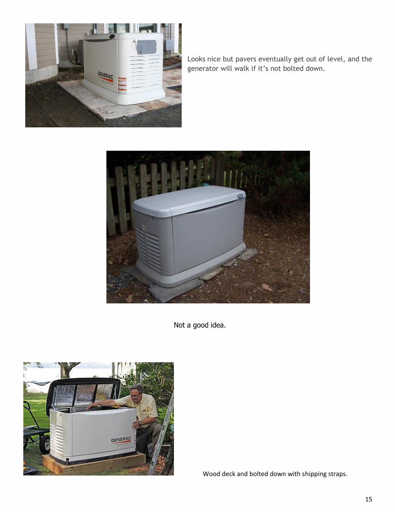
Looks nice but pavers eventually get out of level, and the
generator will walk if it’s not bolted down.
Not a good idea.
Wood deck and bolted down with shipping straps.
16
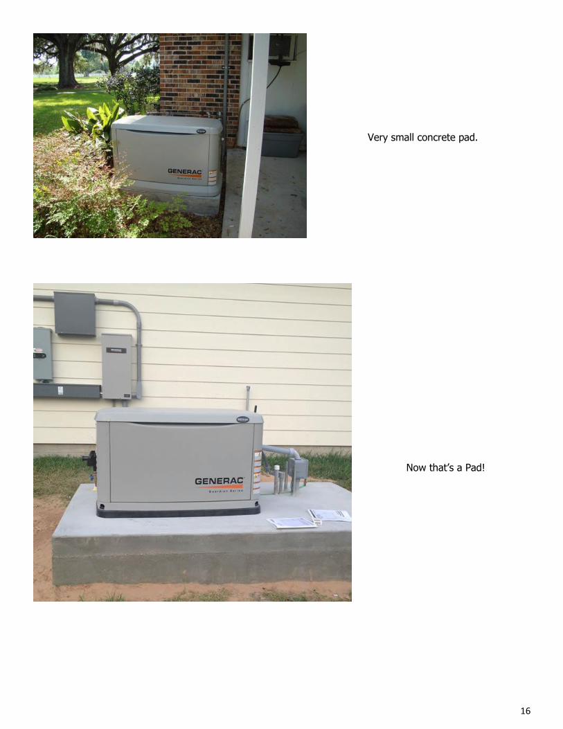
Very small concrete pad.
Now that’s a Pad!
17
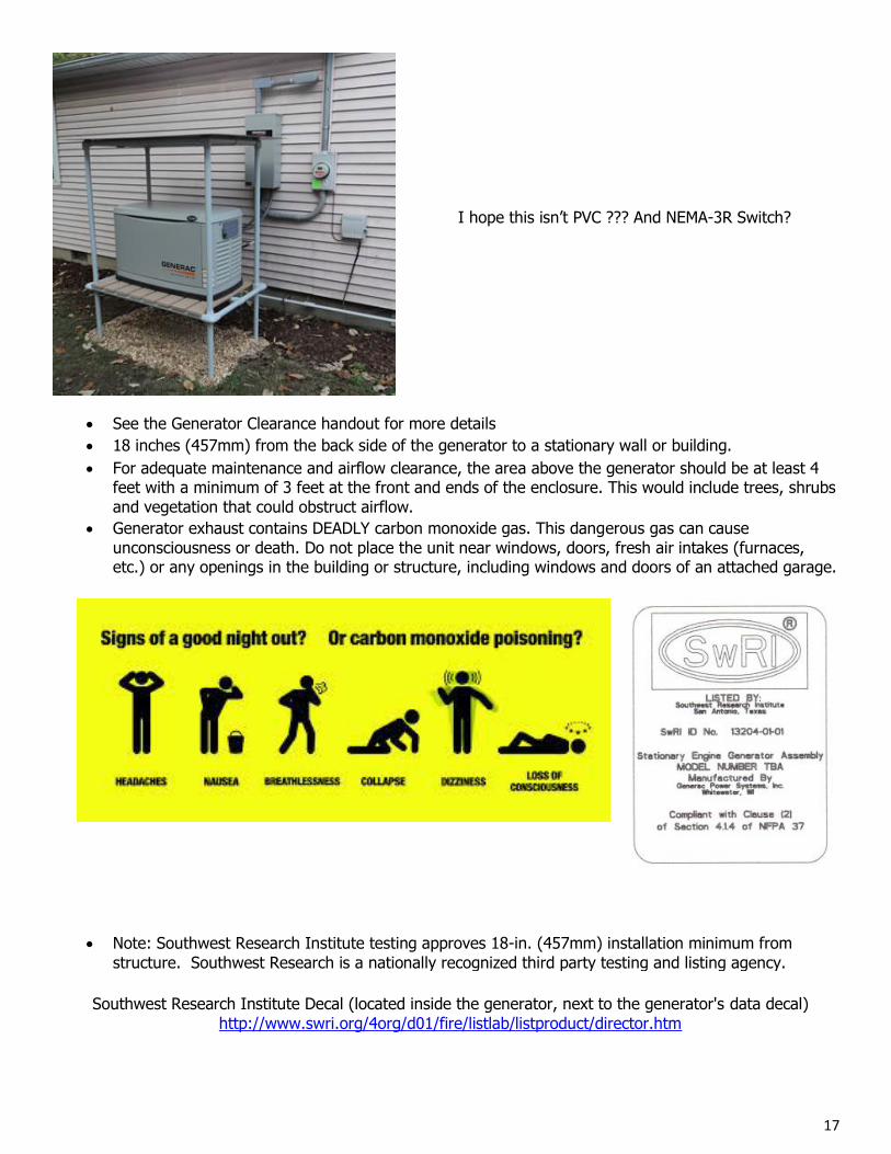
I hope this isn’t PVC ??? And NEMA-3R Switch?
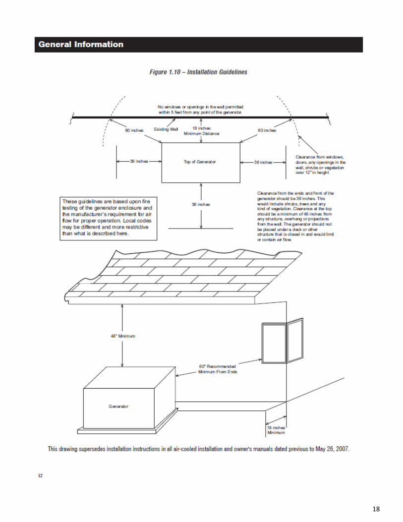
See the Generator Clearance handout for more details
18 inches (457mm) from the back side of the generator to a stationary wall or building.
For adequate maintenance and airflow clearance, the area above the generator should be at least 4 feet with a minimum of 3 feet at the front and ends of the enclosure. This would include trees, shrubs
and vegetation that could obstruct airflow.
Generator exhaust contains DEADLY carbon monoxide gas. This dangerous gas can cause
unconsciousness or death. Do not place the unit near windows, doors, fresh air intakes (furnaces, etc.) or any openings in the building or structure, including windows and doors of an attached garage.
Note: Southwest Research Institute testing approves 18-in. (457mm) installation minimum from
structure. Southwest Research is a nationally recognized third party testing and listing agency.
Southwest Research Institute Decal (located inside the generator, next to the generator's data decal)
http://www.swri.org/4org/d01/fire/listlab/listproduct/director.htm
18
19
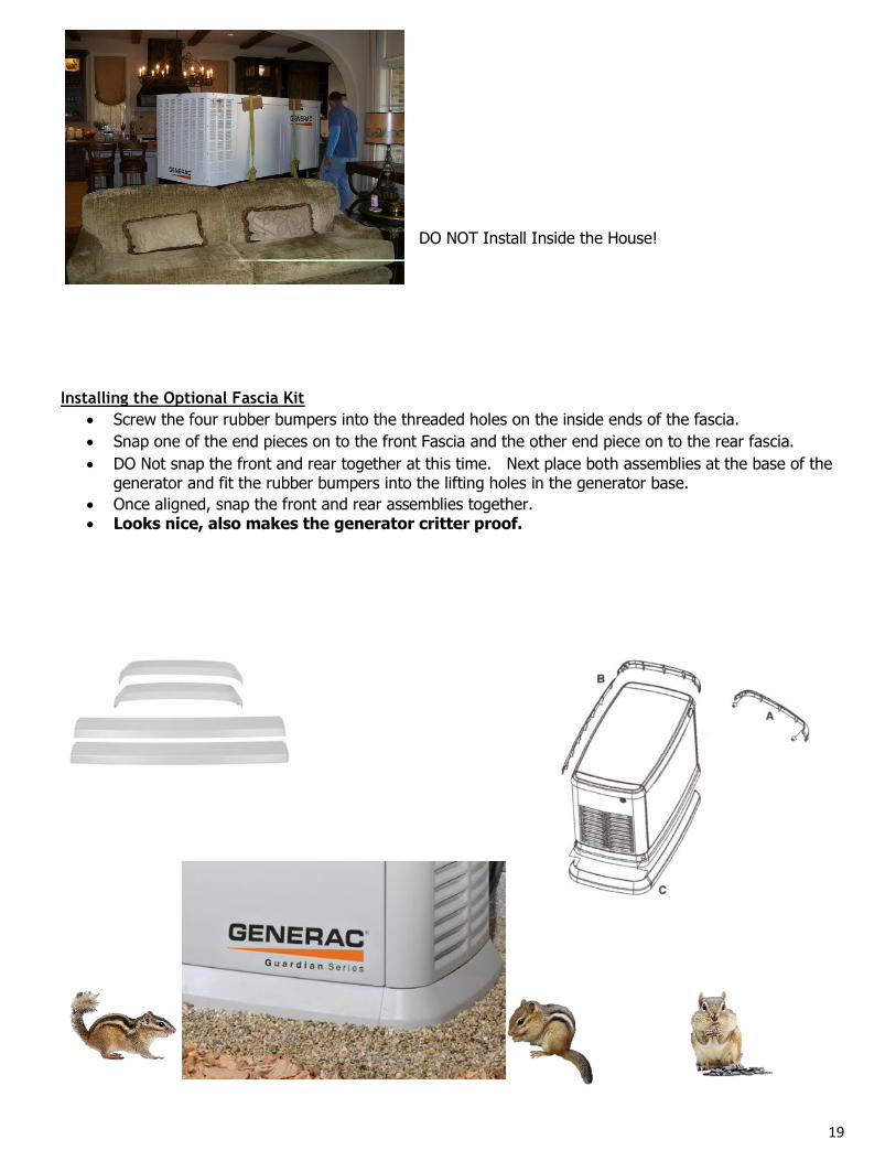
DO NOT Install Inside the House!
Installing the Optional Fascia Kit
Screw the four rubber bumpers into the threaded holes on the inside ends of the fascia.
Snap one of the end pieces on to the front Fascia and the other end piece on to the rear fascia.
DO Not snap the front and rear together at this time. Next place both assemblies at the base of the generator and fit the rubber bumpers into the lifting holes in the generator base.
Once aligned, snap the front and rear assemblies together. Looks nice, also makes the generator critter proof.
20
Gaseous Fuel Requirements and Installation
This section can be found in:
Page 16 thru 21 in the Installation Guidelines Air-cooled Generators
Page 7 thru 9 in the Generac Generator Sizing Guide
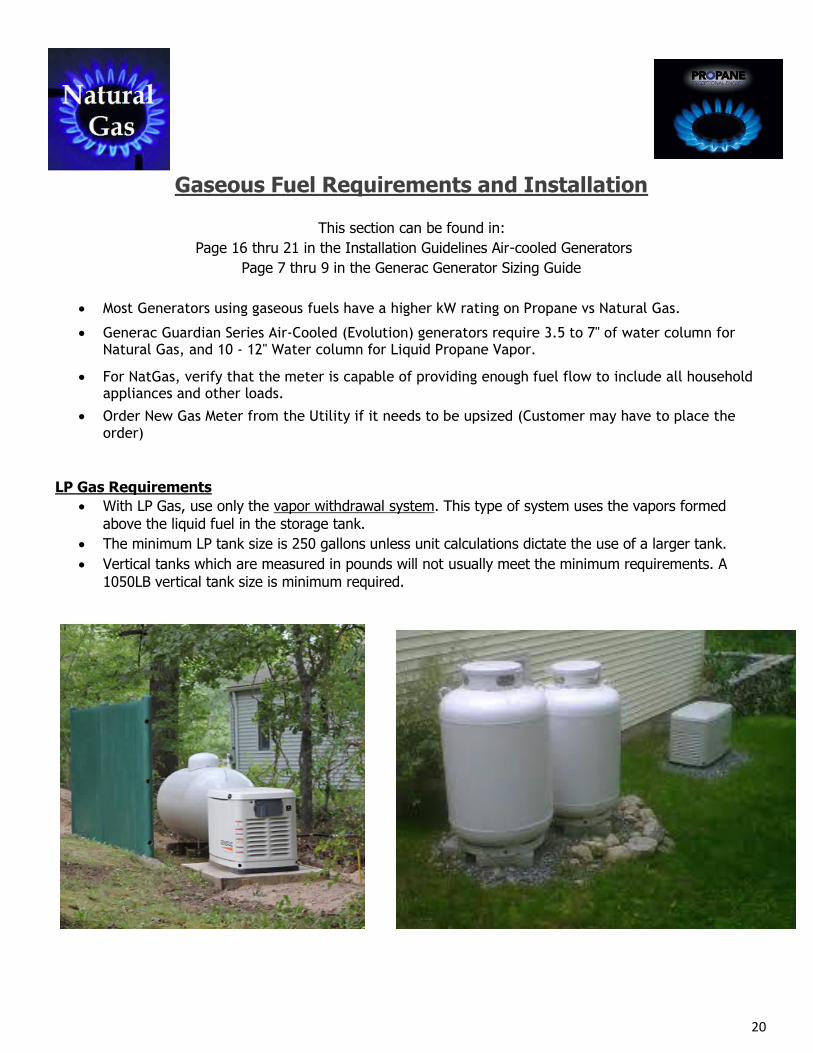
Most Generators using gaseous fuels have a higher kW rating on Propane vs Natural Gas.
Generac Guardian Series Air-Cooled (Evolution) generators require 3.5 to 7" of water column for Natural Gas, and 10 - 12" Water column for Liquid Propane Vapor.
For NatGas, verify that the meter is capable of providing enough fuel flow to include all household appliances and other loads.
Order New Gas Meter from the Utility if it needs to be upsized (Customer may have to place the order)
LP Gas Requirements
With LP Gas, use only the vapor withdrawal system. This type of system uses the vapors formed
above the liquid fuel in the storage tank.
The minimum LP tank size is 250 gallons unless unit calculations dictate the use of a larger tank.
Vertical tanks which are measured in pounds will not usually meet the minimum requirements. A
1050LB vertical tank size is minimum required.
21
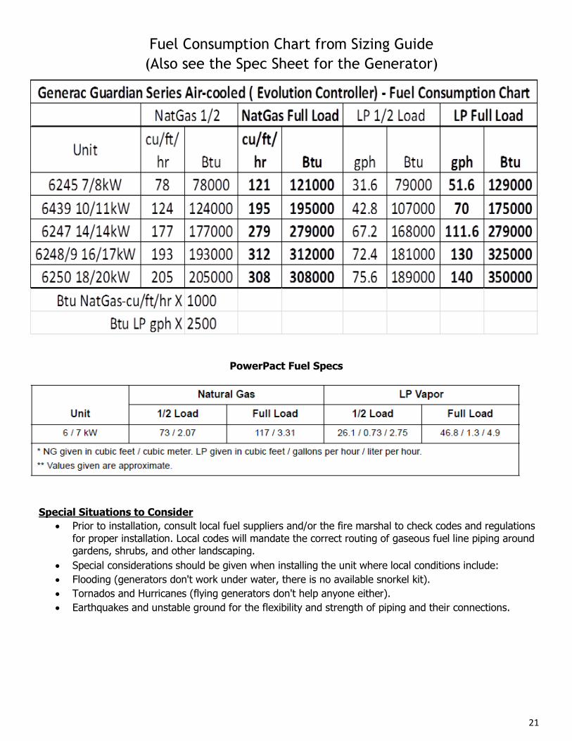
Fuel Consumption Chart from Sizing Guide
(Also see the Spec Sheet for the Generator)
PowerPact Fuel Specs
Special Situations to Consider
Prior to installation, consult local fuel suppliers and/or the fire marshal to check codes and regulations
for proper installation. Local codes will mandate the correct routing of gaseous fuel line piping around gardens, shrubs, and other landscaping.
Special considerations should be given when installing the unit where local conditions include:
Flooding (generators don't work under water, there is no available snorkel kit).
Tornados and Hurricanes (flying generators don't help anyone either).
Earthquakes and unstable ground for the flexibility and strength of piping and their connections.
22
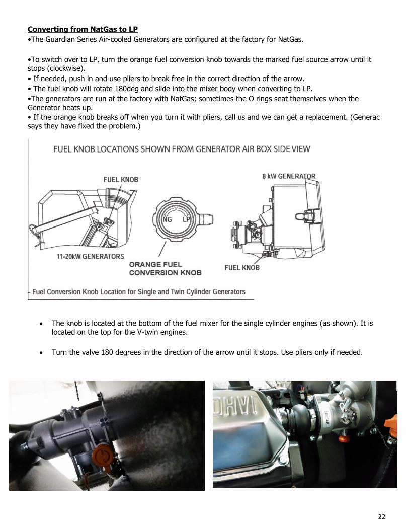
Converting from NatGas to LP
•The Guardian Series Air-cooled Generators are configured at the factory for NatGas.
•To switch over to LP, turn the orange fuel conversion knob towards the marked fuel source arrow until it stops (clockwise).
• If needed, push in and use pliers to break free in the correct direction of the arrow.
• The fuel knob will rotate 180deg and slide into the mixer body when converting to LP.
•The generators are run at the factory with NatGas; sometimes the O rings seat themselves when the
Generator heats up.
• If the orange knob breaks off when you turn it with pliers, call us and we can get a replacement. (Generac says they have fixed the problem.)
The knob is located at the bottom of the fuel mixer for the single cylinder engines (as shown). It is located on the top for the V-twin engines.
Turn the valve 180 degrees in the direction of the arrow until it stops. Use pliers only if needed.

23
PowerPact – Use pliers to squeeze clamp and remove hose from fuel inlet
Remove the NatGas Jet and insert the Propane Jet, reinstall the hose.
Basic Requirements for Gas Piping All pipe sizing construction and layout must comply with NFPA 54 for NatGas and NFPA 58 for LP.
Always use AGA approved gas pipe and a quality sealant or joint compound on all threaded fittings.
All installed gaseous fuel piping must be purged and leak tested prior to initial startup in accordance
with local codes, standards, and regulations.
Gaseous fuels such as NatGas and LP are highly explosive. NO Leakage is permitted! NatGas is lighter
than air, tends to collect in high areas. LP is heavier than air and tends to settle in low areas.
24
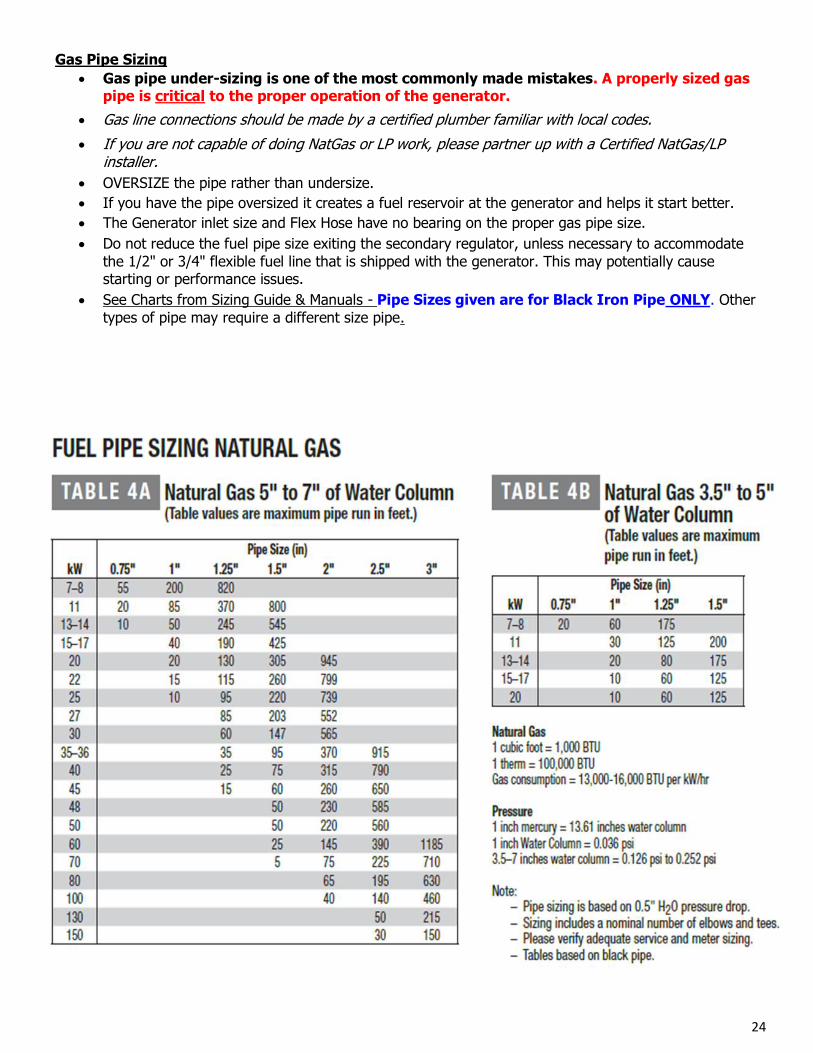
Gas Pipe Sizing
Gas pipe under-sizing is one of the most commonly made mistakes. A properly sized gas pipe is critical to the proper operation of the generator.
Gas line connections should be made by a certified plumber familiar with local codes.
If you are not capable of doing NatGas or LP work, please partner up with a Certified NatGas/LP installer.
OVERSIZE the pipe rather than undersize.
If you have the pipe oversized it creates a fuel reservoir at the generator and helps it start better.
The Generator inlet size and Flex Hose have no bearing on the proper gas pipe size.
Do not reduce the fuel pipe size exiting the secondary regulator, unless necessary to accommodate
the 1/2" or 3/4" flexible fuel line that is shipped with the generator. This may potentially cause starting or performance issues.
See Charts from Sizing Guide & Manuals - Pipe Sizes given are for Black Iron Pipe ONLY. Other
types of pipe may require a different size pipe.
25
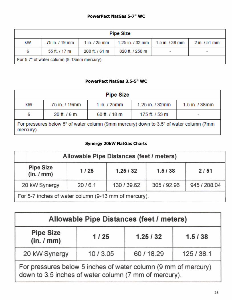
PowerPact NatGas 5-7" WC
PowerPact NatGas 3.5-5" WC
Synergy 20kW NatGas Charts
26
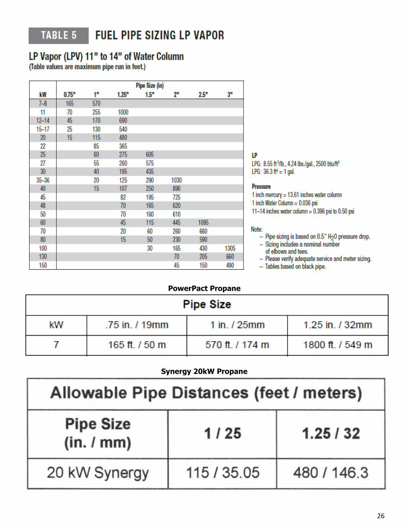
PowerPact Propane
Synergy 20kW Propane
27
Gas Regulator Issues
The Primary Regulator for the propane supply is NOT INCLUDED with the generator.
Note: LP Pipe sizes given in the manual are using a second stage regulator.
When sizing a secondary regulator for LP or High Pressure NatGas, be sure to note the Maximum
individual load capabilities which will be lower than the total capacity. This could impact generator starting performance issues.
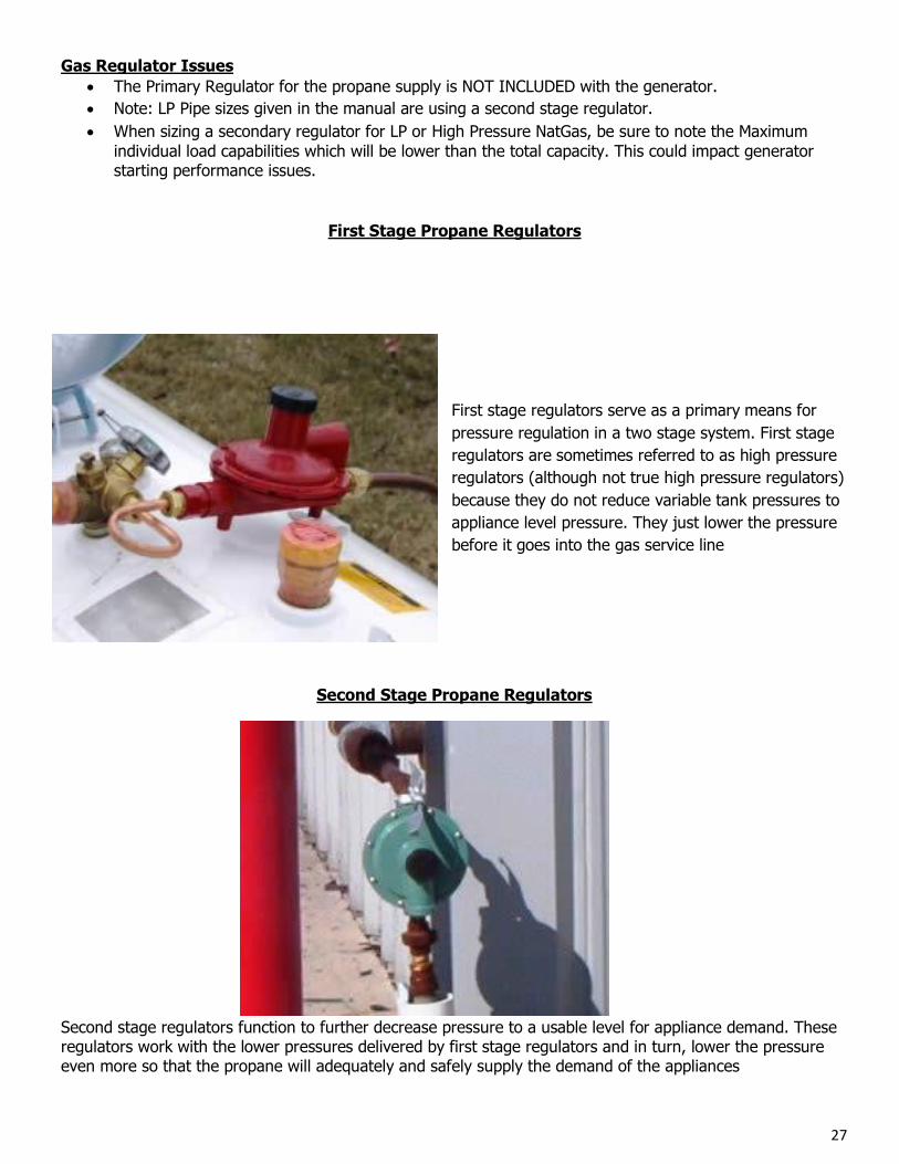
First Stage Propane Regulators
First stage regulators serve as a primary means for
pressure regulation in a two stage system. First stage
regulators are sometimes referred to as high pressure
regulators (although not true high pressure regulators)
because they do not reduce variable tank pressures to
appliance level pressure. They just lower the pressure
before it goes into the gas service line
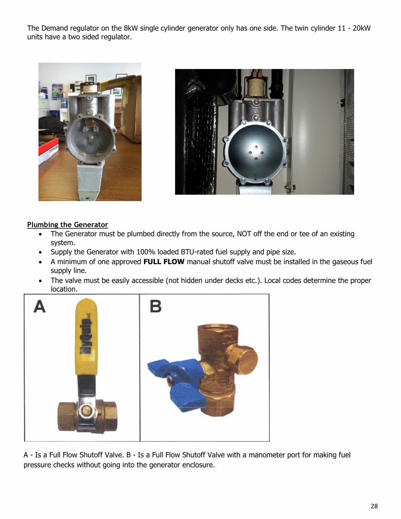
Second Stage Propane Regulators
Second stage regulators function to further decrease pressure to a usable level for appliance demand. These regulators work with the lower pressures delivered by first stage regulators and in turn, lower the pressure even more so that the propane will adequately and safely supply the demand of the appliances
28
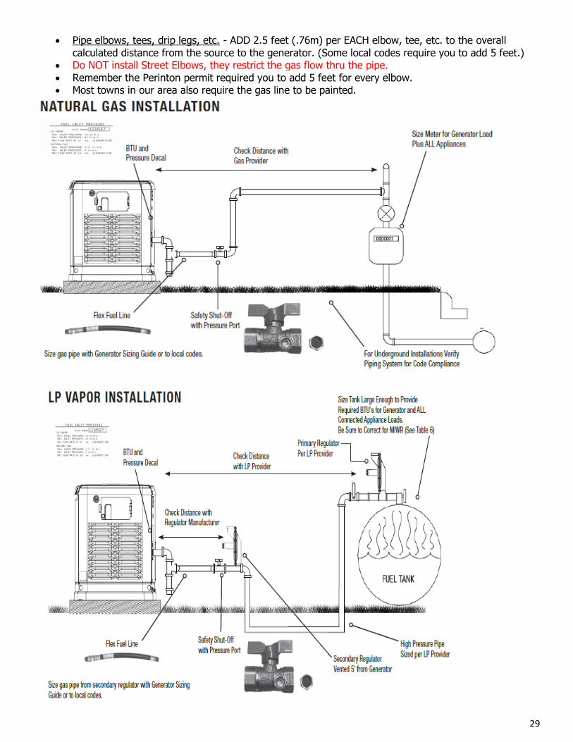
The Demand regulator on the 8kW single cylinder generator only has one side. The twin cylinder 11 - 20kW units have a two sided regulator.
Plumbing the Generator
The Generator must be plumbed directly from the source, NOT off the end or tee of an existing
system.
Supply the Generator with 100% loaded BTU-rated fuel supply and pipe size.
A minimum of one approved FULL FLOW manual shutoff valve must be installed in the gaseous fuel
supply line.
The valve must be easily accessible (not hidden under decks etc.). Local codes determine the proper location.
A - Is a Full Flow Shutoff Valve. B - Is a Full Flow Shutoff Valve with a manometer port for making fuel
pressure checks without going into the generator enclosure.
29
Pipe elbows, tees, drip legs, etc. - ADD 2.5 feet (.76m) per EACH elbow, tee, etc. to the overall
calculated distance from the source to the generator. (Some local codes require you to add 5 feet.) Do NOT install Street Elbows, they restrict the gas flow thru the pipe.
Remember the Perinton permit required you to add 5 feet for every elbow. Most towns in our area also require the gas line to be painted.
30
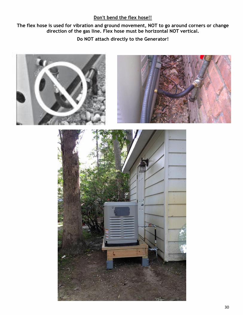
Don't bend the flex hose!!
The flex hose is used for vibration and ground movement, NOT to go around corners or change direction of the gas line. Flex hose must be horizontal NOT vertical.
Do NOT attach directly to the Generator!
31
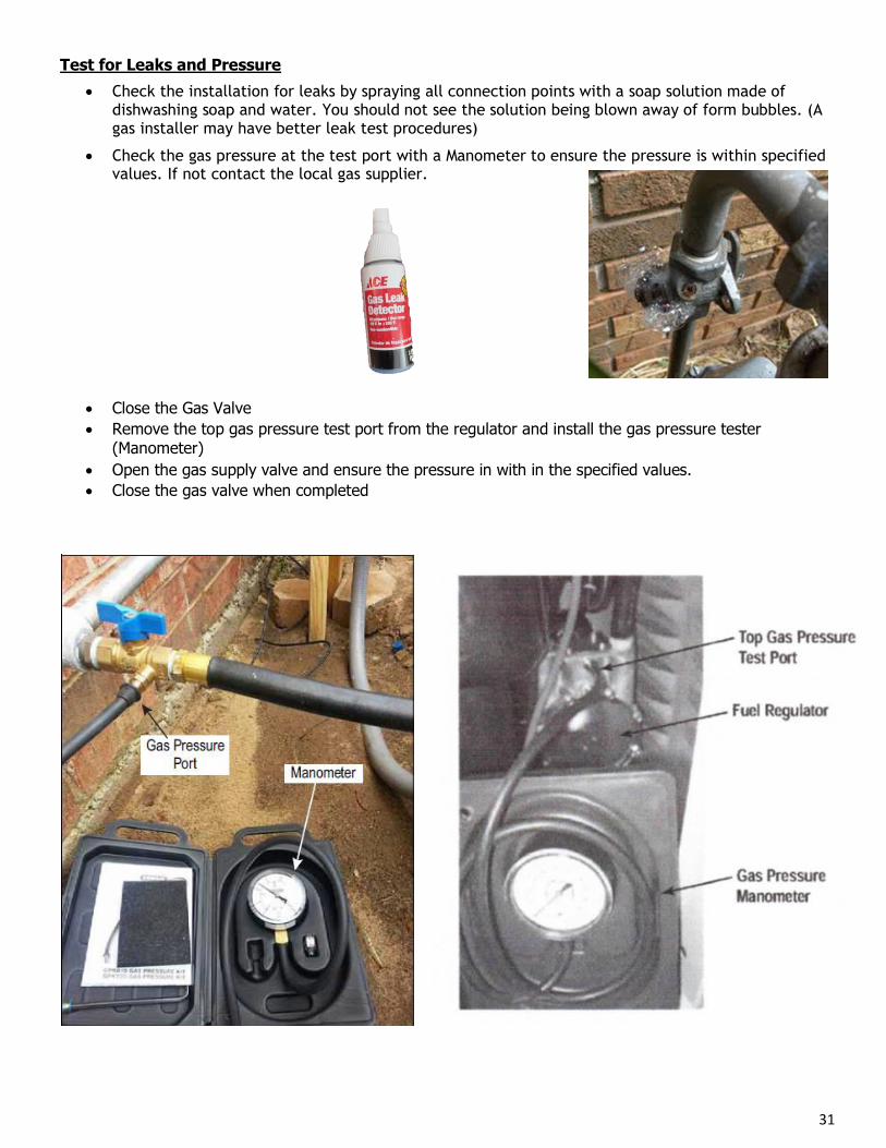
Test for Leaks and Pressure
Check the installation for leaks by spraying all connection points with a soap solution made of dishwashing soap and water. You should not see the solution being blown away of form bubbles. (A gas installer may have better leak test procedures)
Check the gas pressure at the test port with a Manometer to ensure the pressure is within specified values. If not contact the local gas supplier.
Close the Gas Valve
Remove the top gas pressure test port from the regulator and install the gas pressure tester (Manometer)
Open the gas supply valve and ensure the pressure in with in the specified values.
Close the gas valve when completed
32
Transfer Switches GenReady Info:
This section can be found in the GenReady Load Center and Transfer Switch Owner’s Manual, Page 5 and 6.
RTG-EZ Switch Info:
This section can be found in the Installation Guide For Pre-wired Automatic Switch/Load Center Models, pages
4 and 5.
RTSY/T/W, RTSR/P/C info: (RTSW & RTSC will replace RTSY/T & RTSR/P Fall 2015)
This Section can be found in the Owner’s Manual, Automatic Transfer Switch, page 4.
RTSB / RTSI info:
This section can be found in the Owner’s Manual for RTSB200A3 /RTSI200A3, Section 2 page 3.
Transfer Switch Location
This section can be found on pages 2 thru 4 in the GenReady Load Center and Transfer Switch Owner’s
Manual, RTG Installation Guidelines, RTSY/R-B/I Owners Manuals, and LTS Technical Manual
Switch location is up to the contractor, homeowner, and Local Code Official. Generac recommends
that a licensed electrician or an individual with complete knowledge of electricity preform the installation and wiring of the switch and connection to the generator.
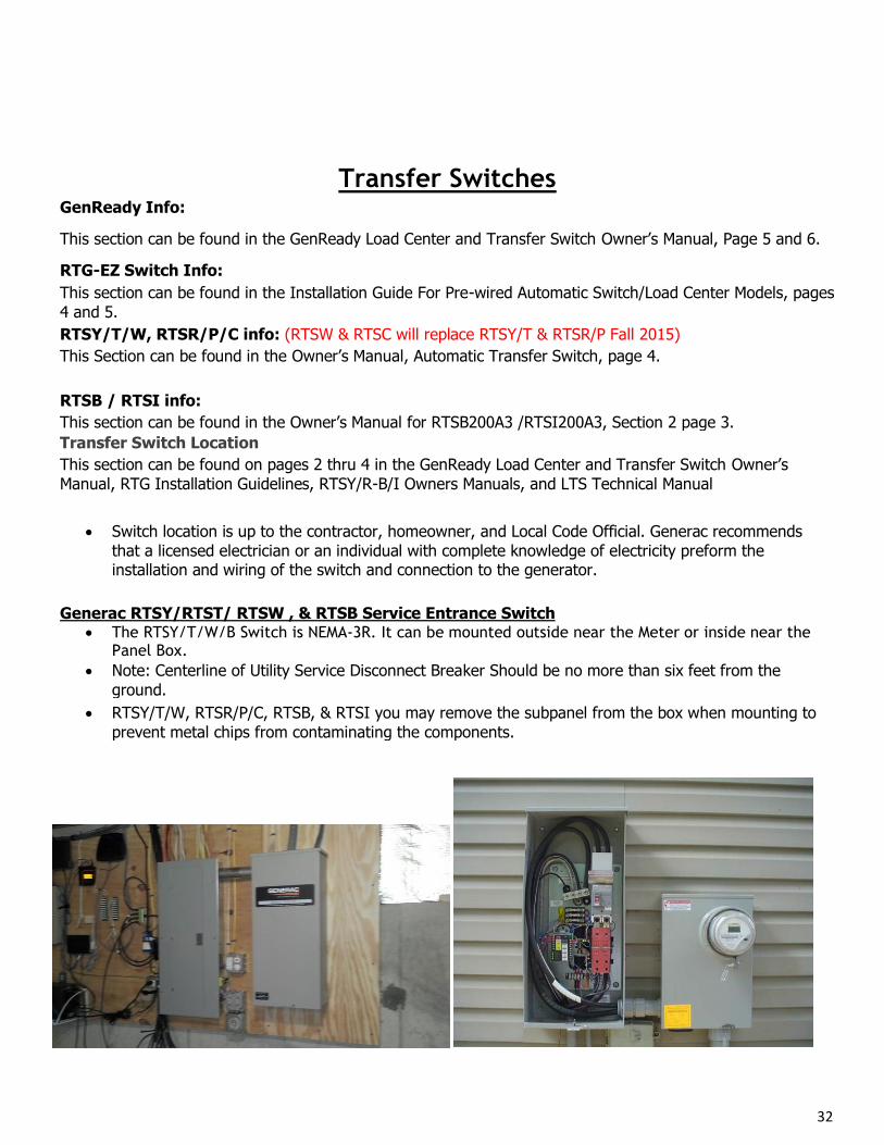
Generac RTSY/RTST/ RTSW , & RTSB Service Entrance Switch The RTSY/T/W/B Switch is NEMA-3R. It can be mounted outside near the Meter or inside near the
Panel Box.
Note: Centerline of Utility Service Disconnect Breaker Should be no more than six feet from the
ground.
RTSY/T/W, RTSR/P/C, RTSB, & RTSI you may remove the subpanel from the box when mounting to
prevent metal chips from contaminating the components.
33
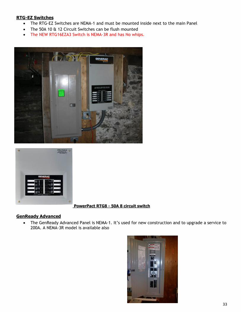
RTG-EZ Switches
The RTG-EZ Switches are NEMA-1 and must be mounted inside next to the main Panel
The 50A 10 & 12 Circuit Switches can be flush mounted
The NEW RTG16EZA3 Switch is NEMA-3R and has No whips.
PowerPact RTG8 - 50A 8 circuit switch
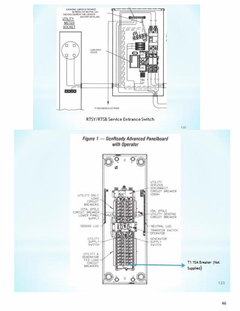
GenReady Advanced
The GenReady Advanced Panel is NEMA-1. It’s used for new construction and to upgrade a service to 200A. A NEMA-3R model is available also
34
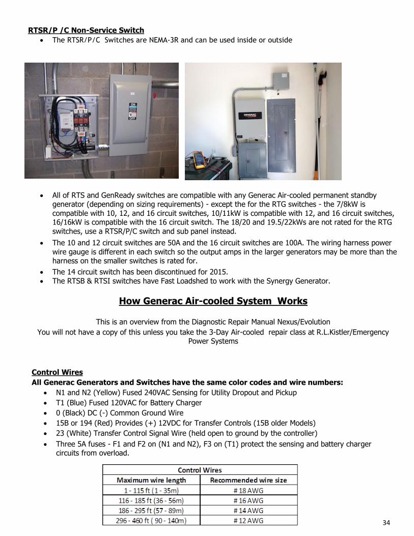
RTSR/P /C Non-Service Switch
The RTSR/P/C Switches are NEMA-3R and can be used inside or outside
All of RTS and GenReady switches are compatible with any Generac Air-cooled permanent standby generator (depending on sizing requirements) - except the for the RTG switches - the 7/8kW is
compatible with 10, 12, and 16 circuit switches, 10/11kW is compatible with 12, and 16 circuit switches, 16/16kW is compatible with the 16 circuit switch. The 18/20 and 19.5/22kWs are not rated for the RTG
switches, use a RTSR/P/C switch and sub panel instead.
The 10 and 12 circuit switches are 50A and the 16 circuit switches are 100A. The wiring harness power
wire gauge is different in each switch so the output amps in the larger generators may be more than the harness on the smaller switches is rated for.
The 14 circuit switch has been discontinued for 2015.
The RTSB & RTSI switches have Fast Loadshed to work with the Synergy Generator.
How Generac Air-cooled System Works
This is an overview from the Diagnostic Repair Manual Nexus/Evolution
You will not have a copy of this unless you take the 3-Day Air-cooled repair class at R.L.Kistler/Emergency Power Systems
Control Wires
All Generac Generators and Switches have the same color codes and wire numbers:
N1 and N2 (Yellow) Fused 240VAC Sensing for Utility Dropout and Pickup
T1 (Blue) Fused 120VAC for Battery Charger
0 (Black) DC (-) Common Ground Wire
15B or 194 (Red) Provides (+) 12VDC for Transfer Controls (15B older Models)
23 (White) Transfer Control Signal Wire (held open to ground by the controller)
Three 5A fuses - F1 and F2 on (N1 and N2), F3 on (T1) protect the sensing and battery charger circuits from overload.

35
Generac Control Cable is 18AWG 7 conductor TFFN 600V
90degC dry, 75degC wet, UL Listed Type
TC-ER UL1277
Probably requires 300-600V rated wire. Thermostat wire will not meet code. N1, N2, & T12 are 120V. Must meet local
code.
Also available two sizes of Generac Power /Control Cable.
Power wires & Control wires in one cable.
6-17kW has #6-3, #8-1, #18-6 conductors.
20-22kW has #3-3, #6-1, #18-6 conductors.
Transfer Operation
Generac (RTS switch) Transfer Relays are controlled by the controller in the Generator set.
The transfer relay gets 12VDC from the Generator battery via wire 15B or 194 from the generator control board.
The 12VDC circuit is completed through the transfer relay coil and back to the controller via wire 23.
The controller holds wire 23 circuit open to ground (normally open) and the relay is de-energized.
When de-energized, the relay contacts are in their normal condition (one set open and one set closed).
The normally closed relay contacts deliver utility source power to the utility closing circuit of the transfer switch.
The normally open relay contacts will deliver standby source power to the transfer switch standby closing circuit only when the transfer relay is energized by the control panel in the generator.
During automatic system operation, when the generator controller senses that the utility source voltage
has dropped out (via wires N1 and N2), the controller will initiate a ten-second Line Interrupt Delay
Timer. At the end of the ten-second delay, the controller will crank and start the engine.
The Transfer Relay energizes:
The relays normally closed contacts open and the normally open contacts close.
When the normally open contacts close, standby source power is delivered to the standby closing coil
and transfer to standby occurs (you hear the transfer coil engage…it’s loud).
Transfer back to Utility
When the controller senses that utility source voltage has been restored (via wires N1 and N2) for 15 seconds, the wire 23 circuit will open to ground.
The Transfer Relay will de-energize, its normally open contacts will open.
When the normally closed relay contacts close, utility source voltage is delivered to the utility closing
coil to energize the coil. Transfer back to utility occurs.
36
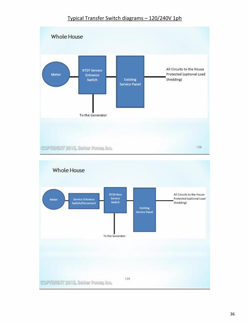
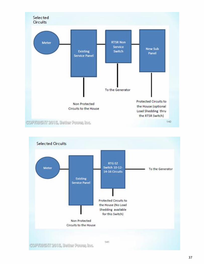
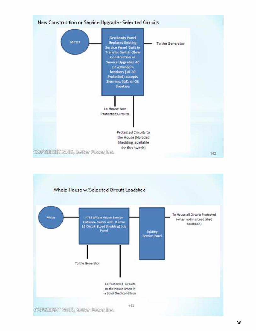
Typical Transfer Switch diagrams – 120/240V 1ph
37
38
39
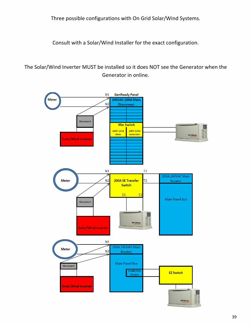
Three possible configurations with On Grid Solar/Wind Systems.
Consult with a Solar/Wind Installer for the exact configuration.
The Solar/Wind Inverter MUST be installed so it does NOT see the Generator when the
Generator in online.
40
How to wire Transfer Switches
All Generac Transfer Switches have the same basic wiring.
See the Manuals, Install Guides, and Handout for detailed instructions.
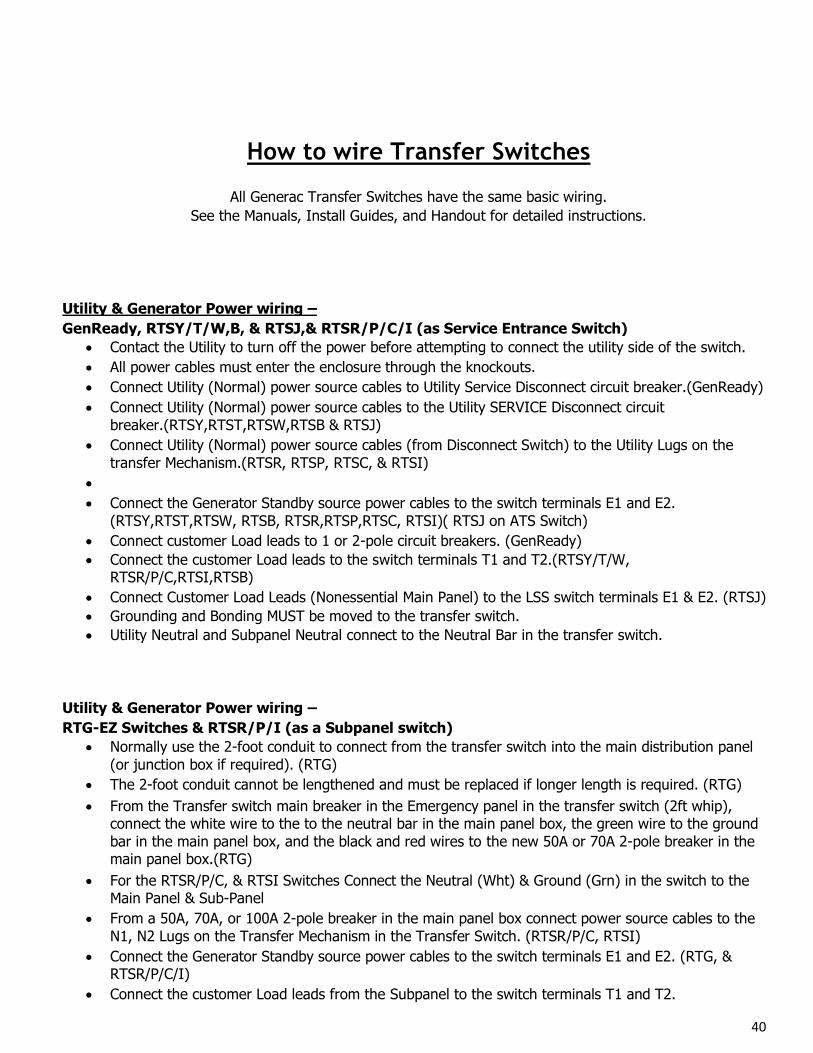
Utility & Generator Power wiring –
GenReady, RTSY/T/W,B, & RTSJ,& RTSR/P/C/I (as Service Entrance Switch)
Contact the Utility to turn off the power before attempting to connect the utility side of the switch.
All power cables must enter the enclosure through the knockouts.
Connect Utility (Normal) power source cables to Utility Service Disconnect circuit breaker.(GenReady)
Connect Utility (Normal) power source cables to the Utility SERVICE Disconnect circuit
breaker.(RTSY,RTST,RTSW,RTSB & RTSJ)
Connect Utility (Normal) power source cables (from Disconnect Switch) to the Utility Lugs on the
transfer Mechanism.(RTSR, RTSP, RTSC, & RTSI)
Connect the Generator Standby source power cables to the switch terminals E1 and E2.
(RTSY,RTST,RTSW, RTSB, RTSR,RTSP,RTSC, RTSI)( RTSJ on ATS Switch)
Connect customer Load leads to 1 or 2-pole circuit breakers. (GenReady)
Connect the customer Load leads to the switch terminals T1 and T2.(RTSY/T/W, RTSR/P/C,RTSI,RTSB)
Connect Customer Load Leads (Nonessential Main Panel) to the LSS switch terminals E1 & E2. (RTSJ)
Grounding and Bonding MUST be moved to the transfer switch.
Utility Neutral and Subpanel Neutral connect to the Neutral Bar in the transfer switch.
Utility & Generator Power wiring –
RTG-EZ Switches & RTSR/P/I (as a Subpanel switch)
Normally use the 2-foot conduit to connect from the transfer switch into the main distribution panel
(or junction box if required). (RTG)
The 2-foot conduit cannot be lengthened and must be replaced if longer length is required. (RTG)
From the Transfer switch main breaker in the Emergency panel in the transfer switch (2ft whip), connect the white wire to the to the neutral bar in the main panel box, the green wire to the ground
bar in the main panel box, and the black and red wires to the new 50A or 70A 2-pole breaker in the main panel box.(RTG)
For the RTSR/P/C, & RTSI Switches Connect the Neutral (Wht) & Ground (Grn) in the switch to the Main Panel & Sub-Panel
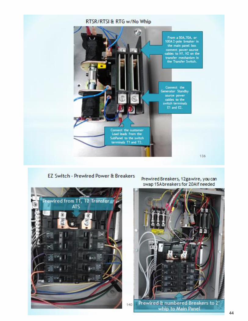
From a 50A, 70A, or 100A 2-pole breaker in the main panel box connect power source cables to the
N1, N2 Lugs on the Transfer Mechanism in the Transfer Switch. (RTSR/P/C, RTSI)
Connect the Generator Standby source power cables to the switch terminals E1 and E2. (RTG, & RTSR/P/C/I)
Connect the customer Load leads from the Subpanel to the switch terminals T1 and T2.
41
(RTSR/P/C, RTSI)
The RTG Switches customer load leads are prewired.
42
43
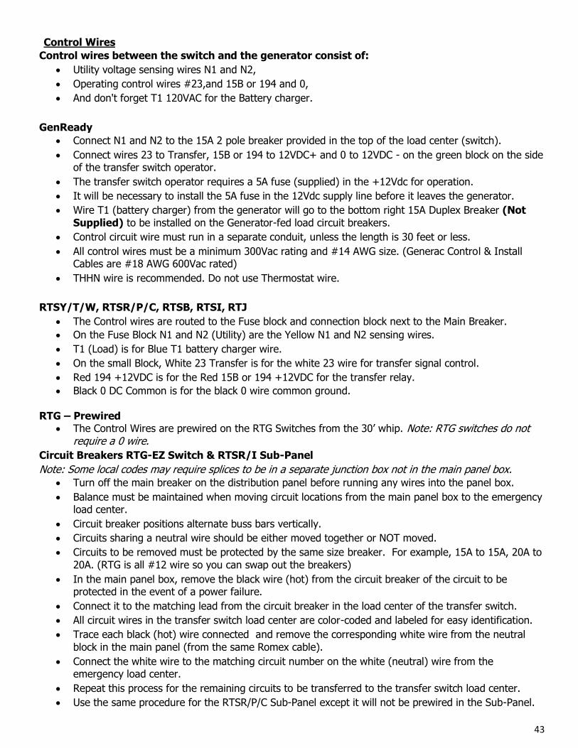
Control Wires
Control wires between the switch and the generator consist of:
Utility voltage sensing wires N1 and N2,
Operating control wires #23,and 15B or 194 and 0,
And don't forget T1 120VAC for the Battery charger.
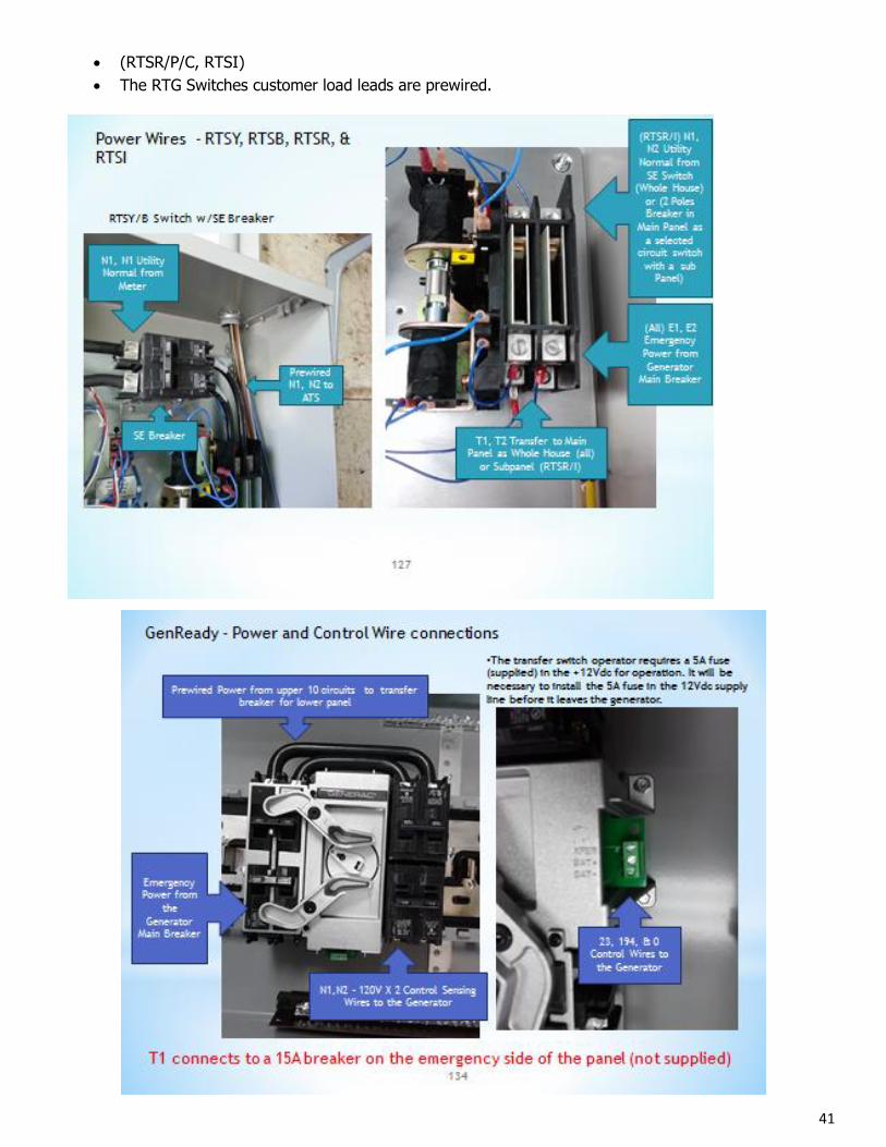
GenReady
Connect N1 and N2 to the 15A 2 pole breaker provided in the top of the load center (switch).
Connect wires 23 to Transfer, 15B or 194 to 12VDC+ and 0 to 12VDC - on the green block on the side of the transfer switch operator.
The transfer switch operator requires a 5A fuse (supplied) in the +12Vdc for operation.
It will be necessary to install the 5A fuse in the 12Vdc supply line before it leaves the generator.
Wire T1 (battery charger) from the generator will go to the bottom right 15A Duplex Breaker (Not
Supplied) to be installed on the Generator-fed load circuit breakers.
Control circuit wire must run in a separate conduit, unless the length is 30 feet or less.
All control wires must be a minimum 300Vac rating and #14 AWG size. (Generac Control & Install Cables are #18 AWG 600Vac rated)
THHN wire is recommended. Do not use Thermostat wire.
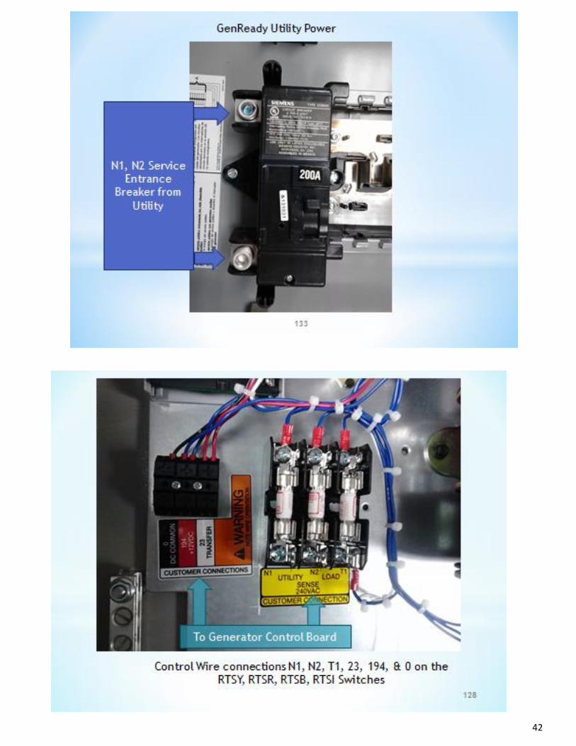
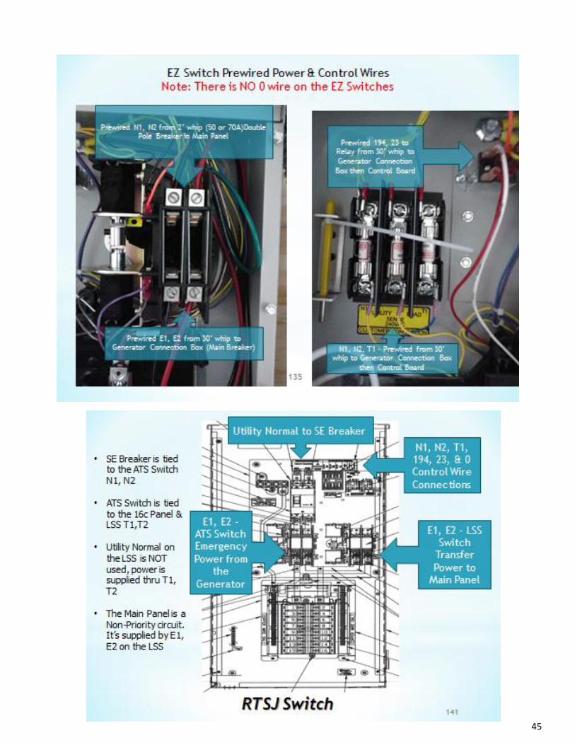
RTSY/T/W, RTSR/P/C, RTSB, RTSI, RTJ
The Control wires are routed to the Fuse block and connection block next to the Main Breaker.
On the Fuse Block N1 and N2 (Utility) are the Yellow N1 and N2 sensing wires.
T1 (Load) is for Blue T1 battery charger wire.
On the small Block, White 23 Transfer is for the white 23 wire for transfer signal control.
Red 194 +12VDC is for the Red 15B or 194 +12VDC for the transfer relay.
Black 0 DC Common is for the black 0 wire common ground.
RTG – Prewired The Control Wires are prewired on the RTG Switches from the 30’ whip. Note: RTG switches do not
require a 0 wire.
Circuit Breakers RTG-EZ Switch & RTSR/I Sub-Panel
Note: Some local codes may require splices to be in a separate junction box not in the main panel box. Turn off the main breaker on the distribution panel before running any wires into the panel box.
Balance must be maintained when moving circuit locations from the main panel box to the emergency load center.
Circuit breaker positions alternate buss bars vertically.
Circuits sharing a neutral wire should be either moved together or NOT moved.
Circuits to be removed must be protected by the same size breaker. For example, 15A to 15A, 20A to
20A. (RTG is all #12 wire so you can swap out the breakers)
In the main panel box, remove the black wire (hot) from the circuit breaker of the circuit to be protected in the event of a power failure.
Connect it to the matching lead from the circuit breaker in the load center of the transfer switch.
All circuit wires in the transfer switch load center are color-coded and labeled for easy identification.
Trace each black (hot) wire connected and remove the corresponding white wire from the neutral
block in the main panel (from the same Romex cable).
Connect the white wire to the matching circuit number on the white (neutral) wire from the emergency load center.
Repeat this process for the remaining circuits to be transferred to the transfer switch load center.
Use the same procedure for the RTSR/P/C Sub-Panel except it will not be prewired in the Sub-Panel.
44
45
46
47
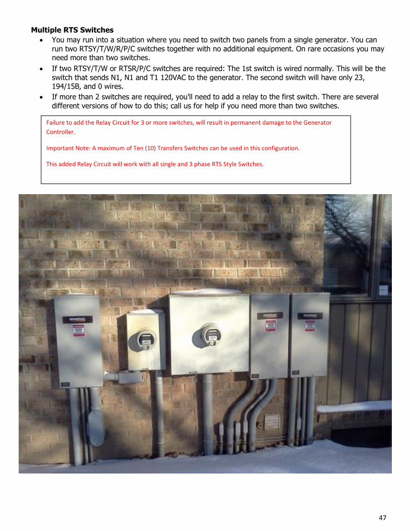
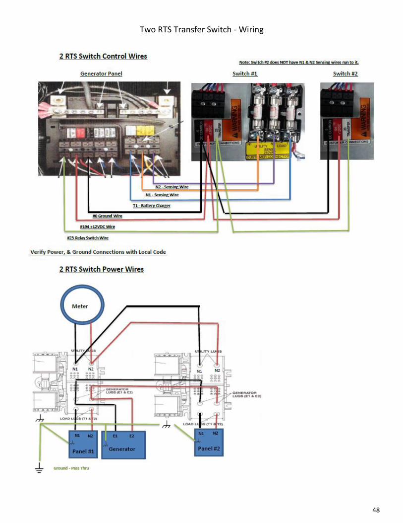
Multiple RTS Switches
You may run into a situation where you need to switch two panels from a single generator. You can
run two RTSY/T/W/R/P/C switches together with no additional equipment. On rare occasions you may need more than two switches.
If two RTSY/T/W or RTSR/P/C switches are required: The 1st switch is wired normally. This will be the
switch that sends N1, N1 and T1 120VAC to the generator. The second switch will have only 23, 194/15B, and 0 wires.
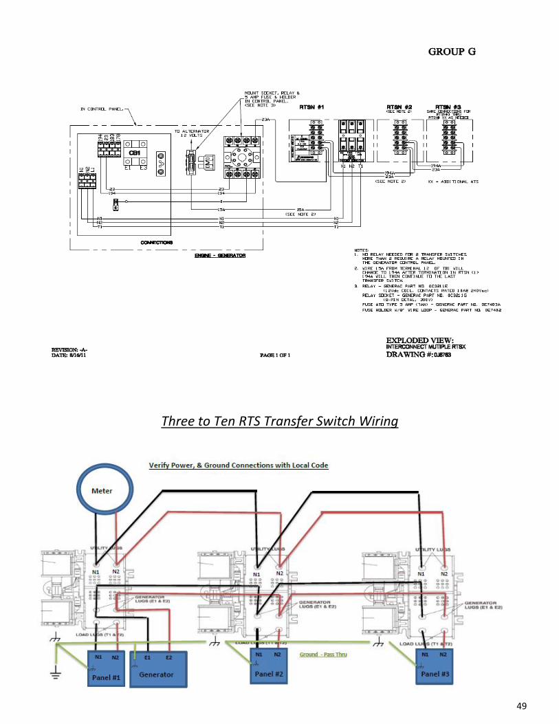
If more than 2 switches are required, you'll need to add a relay to the first switch. There are several
different versions of how to do this; call us for help if you need more than two switches.
Failure to add the Relay Circuit for 3 or more switches, will result in permanent damage to the Generator
Controller.
Important Note: A maximum of Ten (10) Transfers Switches can be used in this configuration.
This added Relay Circuit will work with all single and 3 phase RTS Style Switches.
48
Two RTS Transfer Switch - Wiring
49
Three to Ten RTS Transfer Switch Wiring
50
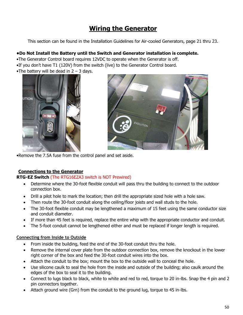
Wiring the Generator
This section can be found in the Installation Guidelines for Air-cooled Generators, page 21 thru 23.
•Do Not Install the Battery until the Switch and Generator installation is complete.
•The Generator Control board requires 12VDC to operate when the Generator is off.
•If you don’t have T1 (120V) from the switch (live) to the Generator Control board.
•The battery will be dead in 2 – 3 days.
•Remove the 7.5A fuse from the control panel and set aside.
Connections to the Generator
RTG-EZ Switch (The RTG16EZA3 switch is NOT Prewired)
Determine where the 30-foot flexible conduit will pass thru the building to connect to the outdoor connection box.
Drill a pilot hole to mark the location; then drill the appropriate sized hole with a hole saw.
Then route the 30-foot conduit along the ceiling/floor joists and wall studs to the hole.
The 30-foot flexible conduit may be lengthened a maximum of 15 feet using the same conductor size
and conduit diameter.
If more than 45 feet is required, replace the entire whip with the appropriate conductor and conduit.
The 5-foot conduit cannot be lengthened either and must be replaced if longer length is required.
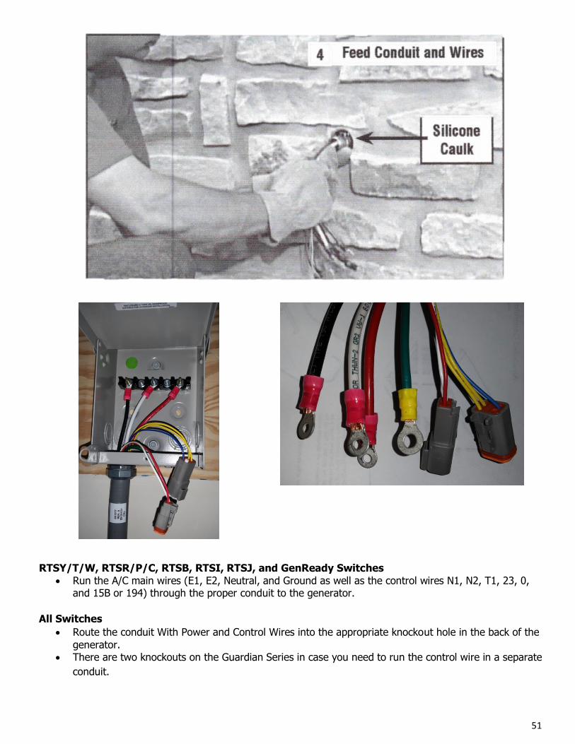
Connecting from Inside to Outside
From inside the building, feed the end of the 30-foot conduit thru the hole.
Remove the internal cover plate from the outdoor connection box, remove the knockout in the lower
right corner of the box and feed the 30-foot conduit wires into the box.
Attach the conduit to the box; mount the box to the outside wall to conceal the hole.
Use silicone caulk to seal the hole from the inside and outside of the building; also caulk around the edges of the box to seal it to the building.
Connect to lugs black to black, white to white and red to red, torque to 20 in-lbs. Snap the 4 pin and 2
pin connectors together.
Attach ground wire (Grn) from the conduit to the ground lug, torque to 45 in-lbs.
51
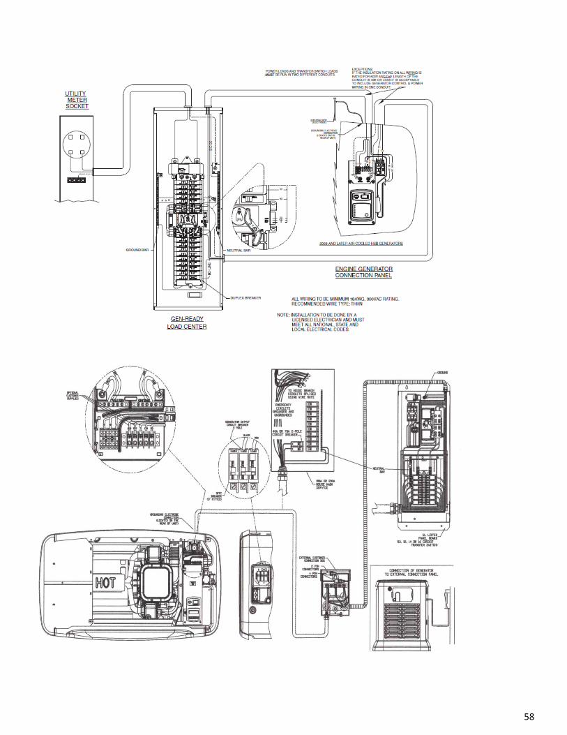
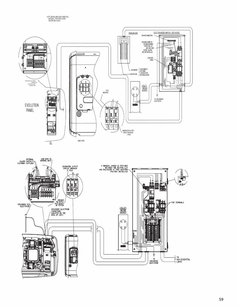
RTSY/T/W, RTSR/P/C, RTSB, RTSI, RTSJ, and GenReady Switches
Run the A/C main wires (E1, E2, Neutral, and Ground as well as the control wires N1, N2, T1, 23, 0, and 15B or 194) through the proper conduit to the generator.
All Switches
Route the conduit With Power and Control Wires into the appropriate knockout hole in the back of the
generator. There are two knockouts on the Guardian Series in case you need to run the control wire in a separate
conduit.
52
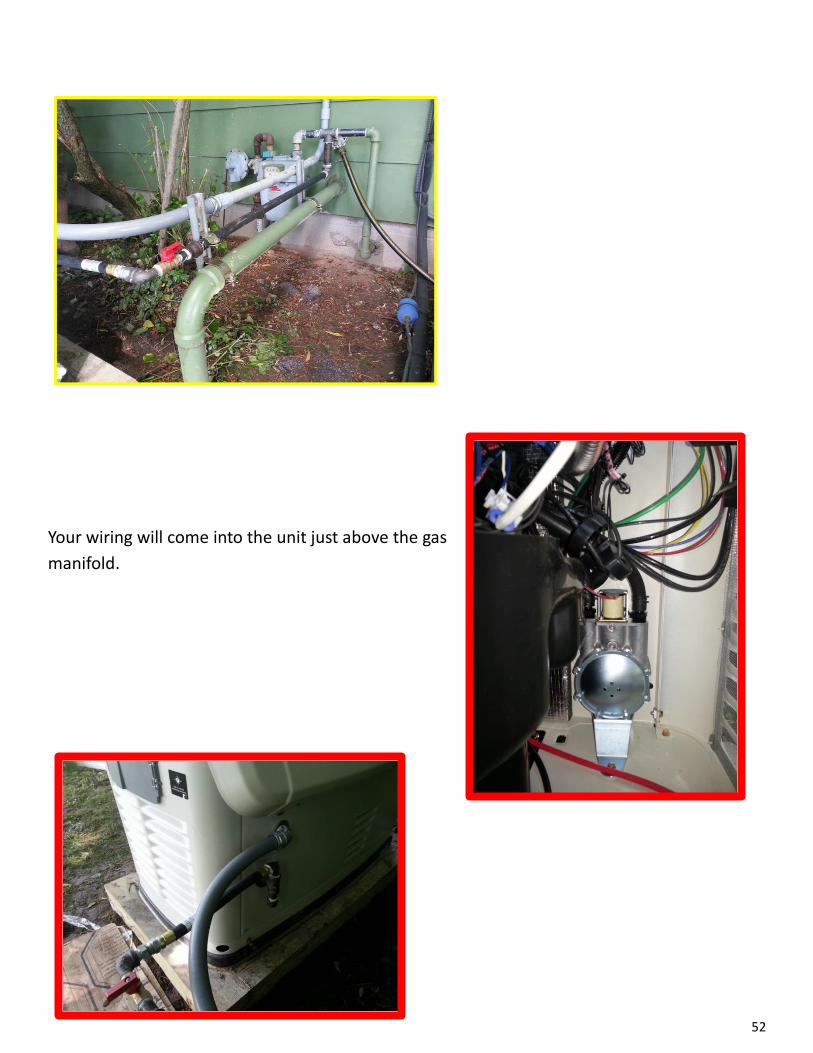
Your wiring will come into the unit just above the gas
manifold.
53
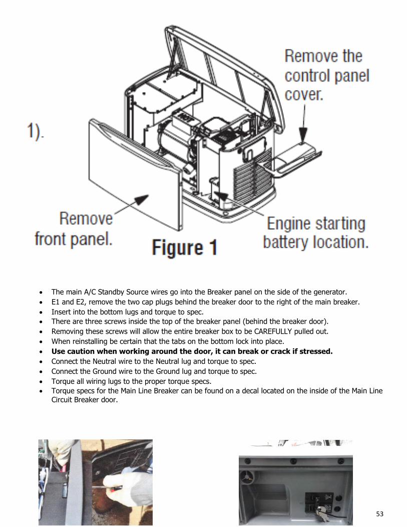
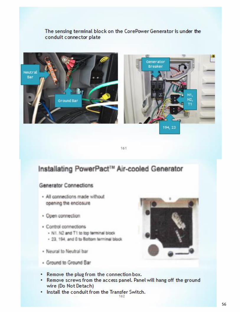
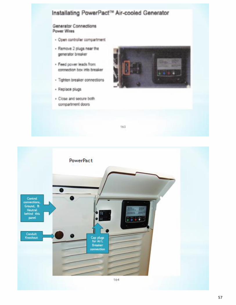
The main A/C Standby Source wires go into the Breaker panel on the side of the generator.
E1 and E2, remove the two cap plugs behind the breaker door to the right of the main breaker.
Insert into the bottom lugs and torque to spec.
There are three screws inside the top of the breaker panel (behind the breaker door).
Removing these screws will allow the entire breaker box to be CAREFULLY pulled out.
When reinstalling be certain that the tabs on the bottom lock into place.
Use caution when working around the door, it can break or crack if stressed.
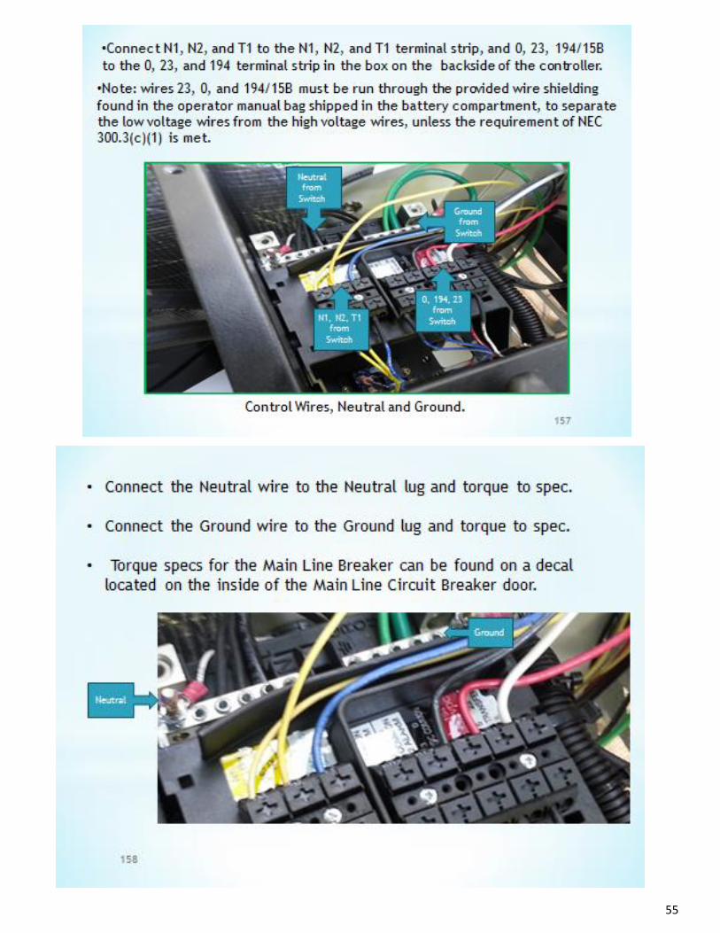
Connect the Neutral wire to the Neutral lug and torque to spec.
Connect the Ground wire to the Ground lug and torque to spec.
Torque all wiring lugs to the proper torque specs.
Torque specs for the Main Line Breaker can be found on a decal located on the inside of the Main Line
Circuit Breaker door.
54
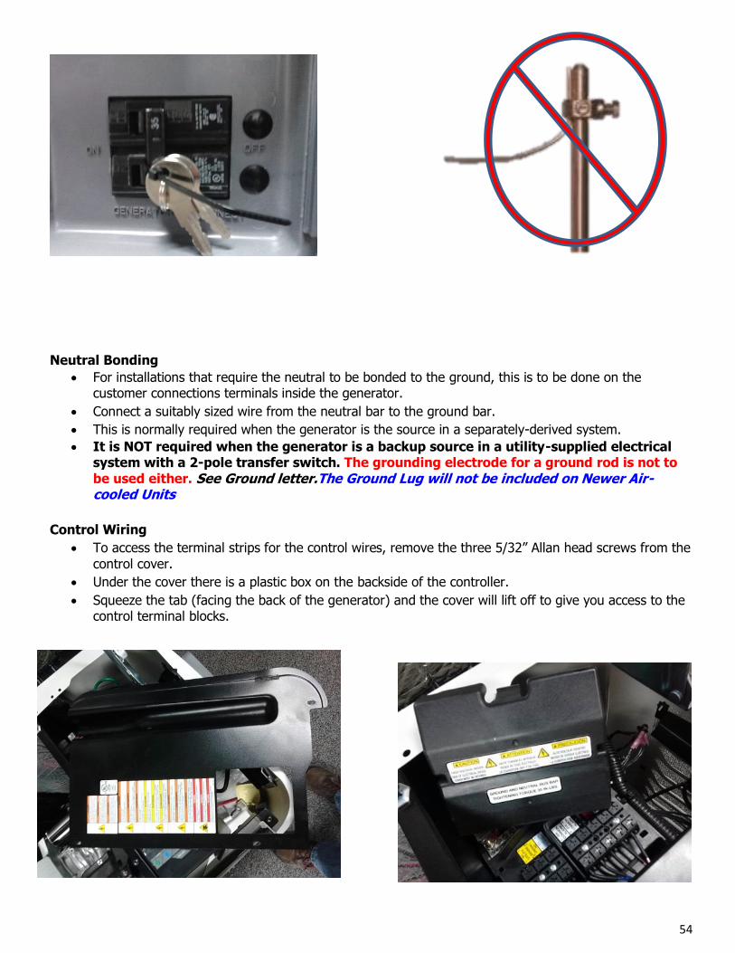
Neutral Bonding
For installations that require the neutral to be bonded to the ground, this is to be done on the customer connections terminals inside the generator.
Connect a suitably sized wire from the neutral bar to the ground bar.
This is normally required when the generator is the source in a separately-derived system.
It is NOT required when the generator is a backup source in a utility-supplied electrical system with a 2-pole transfer switch. The grounding electrode for a ground rod is not to
be used either. See Ground letter.The Ground Lug will not be included on Newer Air-cooled Units
Control Wiring
To access the terminal strips for the control wires, remove the three 5/32” Allan head screws from the
control cover.
Under the cover there is a plastic box on the backside of the controller.
Squeeze the tab (facing the back of the generator) and the cover will lift off to give you access to the control terminal blocks.
55
56
57
58
59
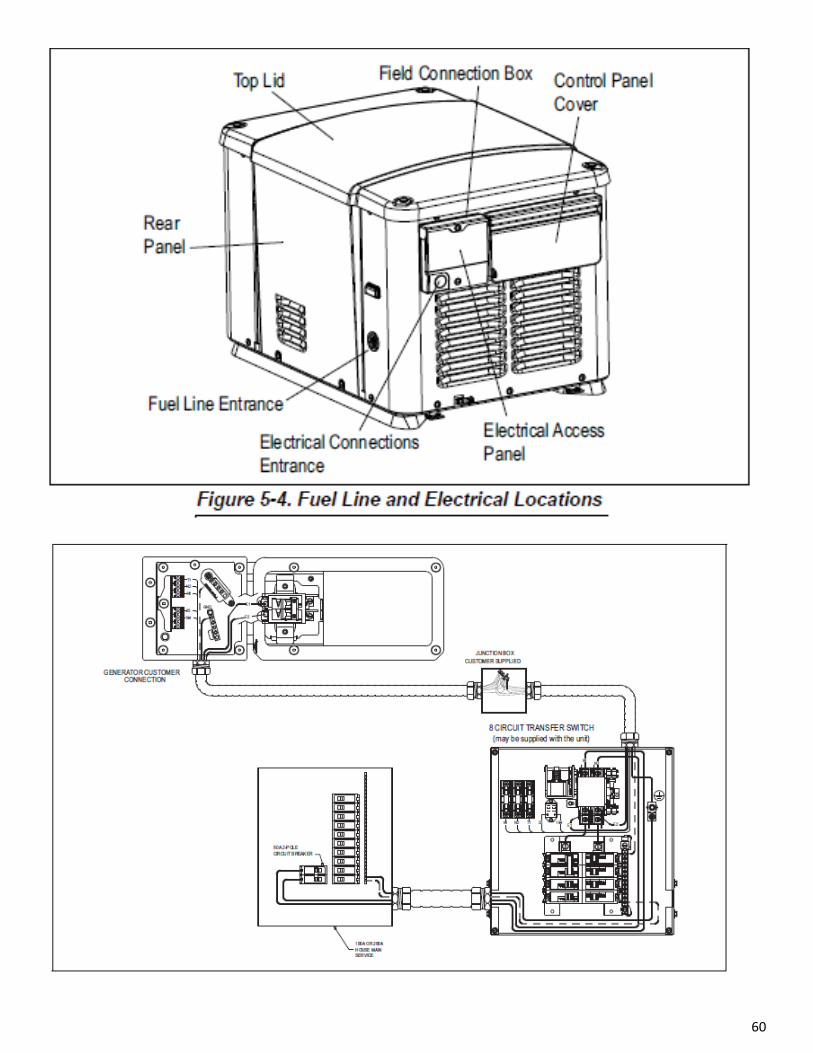
60
61
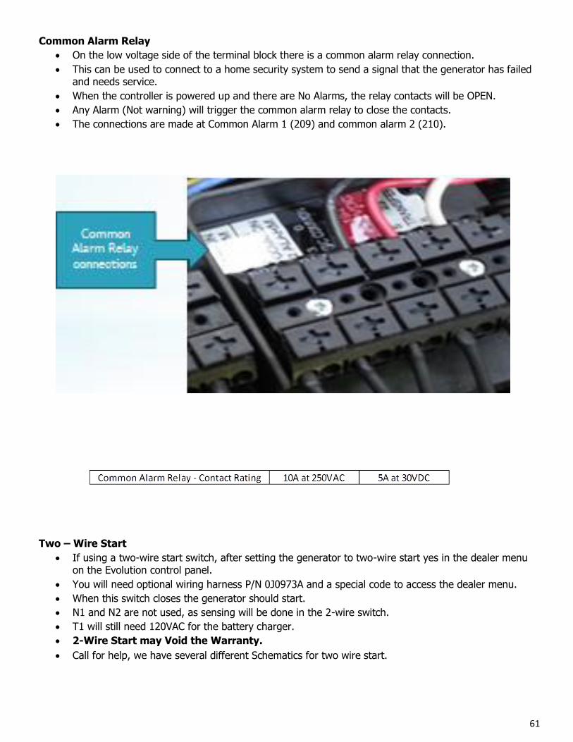
Common Alarm Relay
On the low voltage side of the terminal block there is a common alarm relay connection.
This can be used to connect to a home security system to send a signal that the generator has failed and needs service.
When the controller is powered up and there are No Alarms, the relay contacts will be OPEN.
Any Alarm (Not warning) will trigger the common alarm relay to close the contacts.
The connections are made at Common Alarm 1 (209) and common alarm 2 (210).
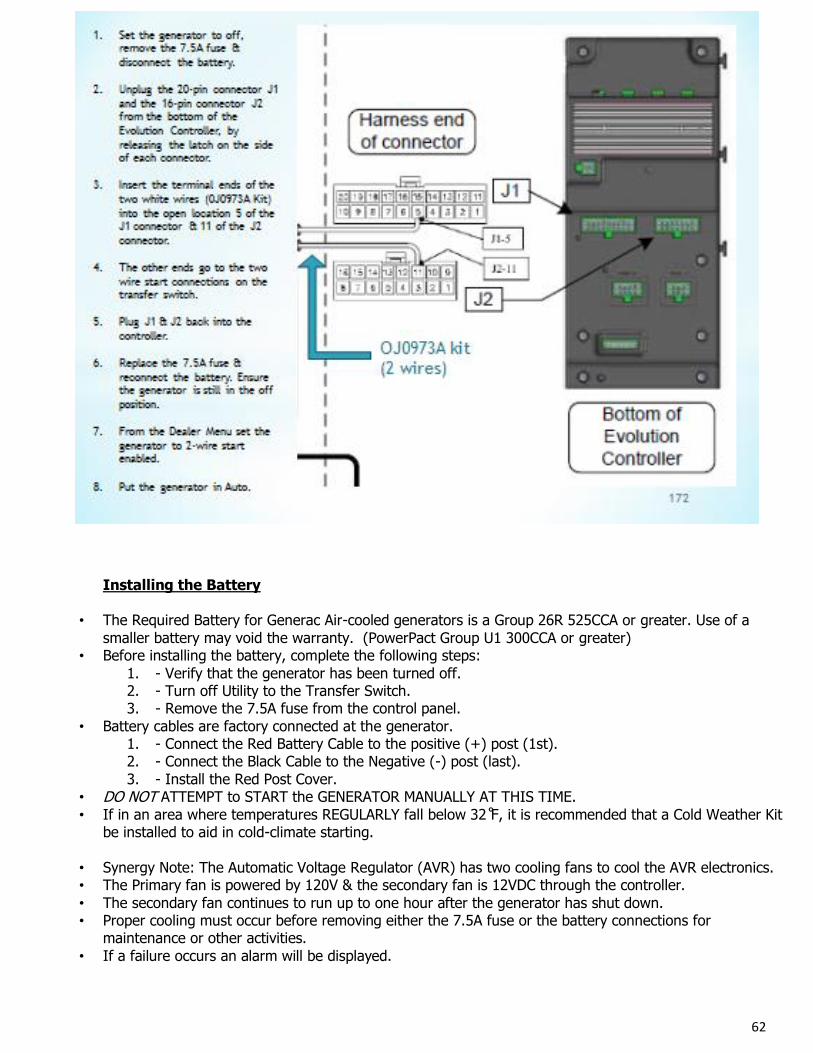
Two – Wire Start
If using a two-wire start switch, after setting the generator to two-wire start yes in the dealer menu on the Evolution control panel.
You will need optional wiring harness P/N 0J0973A and a special code to access the dealer menu.
When this switch closes the generator should start.
N1 and N2 are not used, as sensing will be done in the 2-wire switch.
T1 will still need 120VAC for the battery charger.
2-Wire Start may Void the Warranty.
Call for help, we have several different Schematics for two wire start.
62
Installing the Battery
• The Required Battery for Generac Air-cooled generators is a Group 26R 525CCA or greater. Use of a
smaller battery may void the warranty. (PowerPact Group U1 300CCA or greater) • Before installing the battery, complete the following steps:
1. - Verify that the generator has been turned off. 2. - Turn off Utility to the Transfer Switch. 3. - Remove the 7.5A fuse from the control panel.
• Battery cables are factory connected at the generator. 1. - Connect the Red Battery Cable to the positive (+) post (1st). 2. - Connect the Black Cable to the Negative (-) post (last).
3. - Install the Red Post Cover. • DO NOT ATTEMPT to START the GENERATOR MANUALLY AT THIS TIME.
• If in an area where temperatures REGULARLY fall below 32 F, it is recommended that a Cold Weather Kit be installed to aid in cold-climate starting.
• Synergy Note: The Automatic Voltage Regulator (AVR) has two cooling fans to cool the AVR electronics. • The Primary fan is powered by 120V & the secondary fan is 12VDC through the controller.
• The secondary fan continues to run up to one hour after the generator has shut down. • Proper cooling must occur before removing either the 7.5A fuse or the battery connections for
maintenance or other activities.
• If a failure occurs an alarm will be displayed.
63
Control Panel/Activation-Registration
This section can be found in the Installation Guidelines, Air-cooled Generators, page 24 through 27.
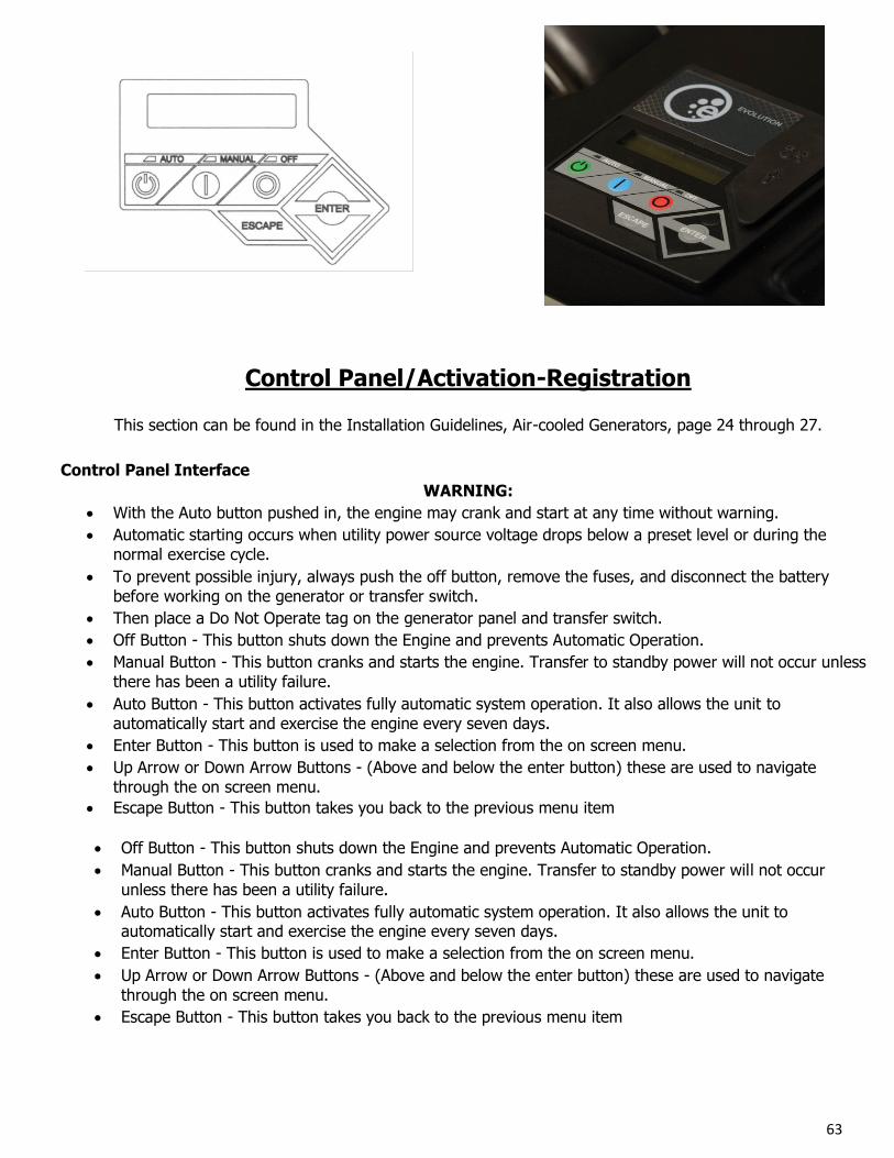
Control Panel Interface
WARNING:
With the Auto button pushed in, the engine may crank and start at any time without warning.
Automatic starting occurs when utility power source voltage drops below a preset level or during the
normal exercise cycle.
To prevent possible injury, always push the off button, remove the fuses, and disconnect the battery
before working on the generator or transfer switch.
Then place a Do Not Operate tag on the generator panel and transfer switch.
Off Button - This button shuts down the Engine and prevents Automatic Operation.
Manual Button - This button cranks and starts the engine. Transfer to standby power will not occur unless
there has been a utility failure.
Auto Button - This button activates fully automatic system operation. It also allows the unit to
automatically start and exercise the engine every seven days.
Enter Button - This button is used to make a selection from the on screen menu.
Up Arrow or Down Arrow Buttons - (Above and below the enter button) these are used to navigate
through the on screen menu.
Escape Button - This button takes you back to the previous menu item
Off Button - This button shuts down the Engine and prevents Automatic Operation.
Manual Button - This button cranks and starts the engine. Transfer to standby power will not occur
unless there has been a utility failure.
Auto Button - This button activates fully automatic system operation. It also allows the unit to automatically start and exercise the engine every seven days.
Enter Button - This button is used to make a selection from the on screen menu.
Up Arrow or Down Arrow Buttons - (Above and below the enter button) these are used to navigate
through the on screen menu.
Escape Button - This button takes you back to the previous menu item
64
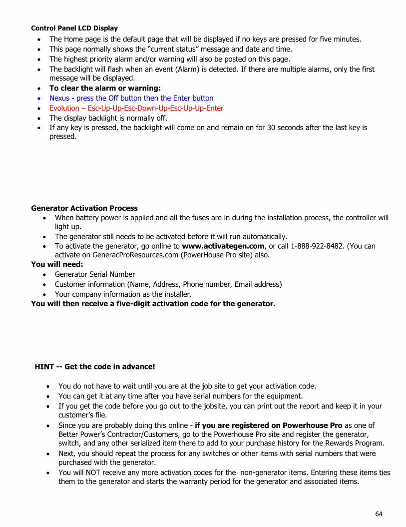
Control Panel LCD Display
The Home page is the default page that will be displayed if no keys are pressed for five minutes.
This page normally shows the “current status” message and date and time.
The highest priority alarm and/or warning will also be posted on this page.
The backlight will flash when an event (Alarm) is detected. If there are multiple alarms, only the first message will be displayed.
To clear the alarm or warning:
Nexus - press the Off button then the Enter button
Evolution – Esc-Up-Up-Esc-Down-Up-Esc-Up-Up-Enter
The display backlight is normally off.
If any key is pressed, the backlight will come on and remain on for 30 seconds after the last key is pressed.
Generator Activation Process
When battery power is applied and all the fuses are in during the installation process, the controller will
light up.
The generator still needs to be activated before it will run automatically.
To activate the generator, go online to www.activategen.com, or call 1-888-922-8482. (You can activate on GeneracProResources.com (PowerHouse Pro site) also.
You will need:
Generator Serial Number
Customer information (Name, Address, Phone number, Email address)
Your company information as the installer.
You will then receive a five-digit activation code for the generator.
HINT -- Get the code in advance!
You do not have to wait until you are at the job site to get your activation code.
You can get it at any time after you have serial numbers for the equipment.
If you get the code before you go out to the jobsite, you can print out the report and keep it in your
customer’s file.
Since you are probably doing this online - if you are registered on Powerhouse Pro as one of
Better Power’s Contractor/Customers, go to the Powerhouse Pro site and register the generator, switch, and any other serialized item there to add to your purchase history for the Rewards Program.
Next, you should repeat the process for any switches or other items with serial numbers that were
purchased with the generator.
You will NOT receive any more activation codes for the non-generator items. Entering these items ties
them to the generator and starts the warranty period for the generator and associated items.
65
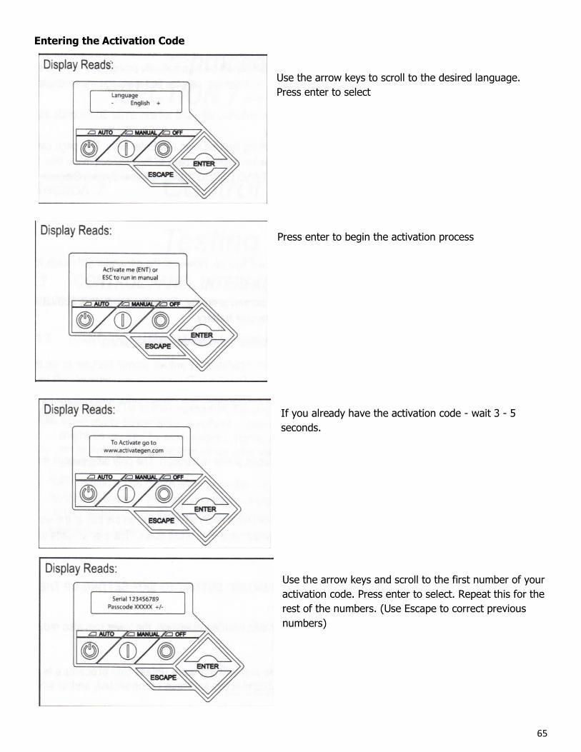
Entering the Activation Code
Use the arrow keys to scroll to the desired language.
Press enter to select
Press enter to begin the activation process
If you already have the activation code - wait 3 - 5
seconds.
Use the arrow keys and scroll to the first number of your
activation code. Press enter to select. Repeat this for the
rest of the numbers. (Use Escape to correct previous
numbers)
66
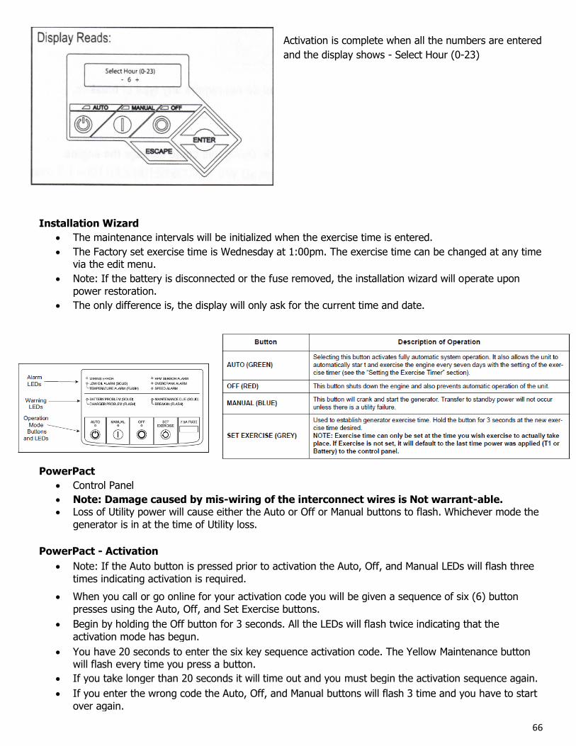
Activation is complete when all the numbers are entered
and the display shows - Select Hour (0-23)
Installation Wizard
The maintenance intervals will be initialized when the exercise time is entered.
The Factory set exercise time is Wednesday at 1:00pm. The exercise time can be changed at any time via the edit menu.
Note: If the battery is disconnected or the fuse removed, the installation wizard will operate upon
power restoration.
The only difference is, the display will only ask for the current time and date.
PowerPact
Control Panel
Note: Damage caused by mis-wiring of the interconnect wires is Not warrant-able. Loss of Utility power will cause either the Auto or Off or Manual buttons to flash. Whichever mode the
generator is in at the time of Utility loss.
PowerPact - Activation
Note: If the Auto button is pressed prior to activation the Auto, Off, and Manual LEDs will flash three
times indicating activation is required.
When you call or go online for your activation code you will be given a sequence of six (6) button
presses using the Auto, Off, and Set Exercise buttons.
Begin by holding the Off button for 3 seconds. All the LEDs will flash twice indicating that the
activation mode has begun.
You have 20 seconds to enter the six key sequence activation code. The Yellow Maintenance button will flash every time you press a button.
If you take longer than 20 seconds it will time out and you must begin the activation sequence again.
If you enter the wrong code the Auto, Off, and Manual buttons will flash 3 time and you have to start
over again.
67
When the sequence is entered correctly all the LEDs will scroll from bottom to top 5 times. The Off
button will light. The Generator is ready to operate.
Setting the Exercise Timer - PowerPact
Note: Do not attempt this until the Generator is ready to be started.
The Exerciser only works in the Auto Mode.
Place the generator in Auto.
Hold the Set Exercise button for 3 seconds.
The generator will start & run an exercise cycle and confirm the setting.
The exercise time must be established at the time will want the exercise to take place.
To change the exercise time, hold the Set Exercise button for 3 seconds at the time you want the new
exercise time to take place.
Initial System Tests
This section can be found in the Installation Guidelines for Air-cooled Generators, pages 27 and 28;
Installation Guide For Pre-wired Automatic Switch/Load Center Models, pages 7 thru 9;
Owner’s Manual Automatic Transfer Switch pages 6 thru 9;
Technical Manual LTS Load Shed Switch pages 5 thru 8.
Interconnect System Self-Test
Upon power up, the controller will go through a system self-test which will check for utility voltage on the DC circuits. (Nexus & Evolution only)
This is done to prevent damage if you have mistakenly connected AC utility power sense wires into the DC terminal block.
If utility voltage is detected, the controller will display a warning message and lock out the generator to prevent damage to the controller.
Power to the controller must be removed to clear this warning.
Utility power must be turned on and present at the N1 and N2 terminals inside the generator control panel for this test to be performed and passed.
BEFORE starting the generator, complete the following:
1. Ensure that the generator is OFF.
2. Set the generator's main circuit breaker to the OFF (or OPEN) Position.
3. Turn off all breakers that will be powered by the generator.
4. Check the engine crankcase oil level and if necessary fill to the dipstick Full mark. The generator comes from the factory with SAE 30 Organic oil. Do Not fill above the Full mark.
5. Check the fuel supply. Gaseous fuel lines must have been properly purged and leak tested. All fuel shutoff valves must be fully open.
Note: The generator is to be run with all appropriate panels in place, including during trouble
shooting by a technician.
During Initial Startup Only:
The generator may exceed the normal number of start attempts and experience an Overcrank fault.
This is due to accumulated air in the fuel system during installation.
Reset the control board, and restart, up to two more times if necessary.
If the generator fails to start, contact a service dealer for assistance.
68
Check Manual Transfer Switch Operation
DANGER - DO NOT attempt manual transfer switch operation until ALL power voltage supplies to the transfer switch have been TURNED OFF!
Failure to turn off all power voltage supplies to the transfer switch will result in extremely hazardous
and possibly fatal electrical shock.
If the automatic function of the switch fails at any time, you probably do NOT want the homeowner to operate the switch manually.
If it needs to be switched manually, that means something is broken and they should call for service!
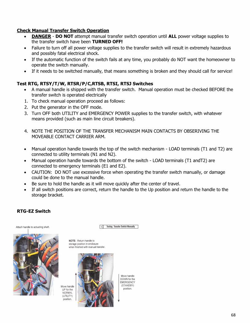
Test RTG, RTSY/T/W, RTSR/P/C,RTSB, RTSI, RTSJ Switches
A manual handle is shipped with the transfer switch. Manual operation must be checked BEFORE the
transfer switch is operated electrically
1. To check manual operation proceed as follows:
2. Put the generator in the OFF mode.
3. Turn OFF both UTILITY and EMERGENCY POWER supplies to the transfer switch, with whatever means provided (such as main line circuit breakers).
4. NOTE THE POSITION OF THE TRANSFER MECHANISM MAIN CONTACTS BY OBSERIVING THE
MOVEABLE CONTACT CARRIER ARM.
Manual operation handle towards the top of the switch mechanism - LOAD terminals (T1 and T2) are connected to utility terminals (N1 and N2).
Manual operation handle towards the bottom of the switch - LOAD terminals (T1 andT2) are
connected to emergency terminals (E1 and E2).
CAUTION: DO NOT use excessive force when operating the transfer switch manually, or damage could be done to the manual handle.
Be sure to hold the handle as it will move quickly after the center of travel.
If all switch positions are correct, return the handle to the Up position and return the handle to the storage bracket.
RTG-EZ Switch
69
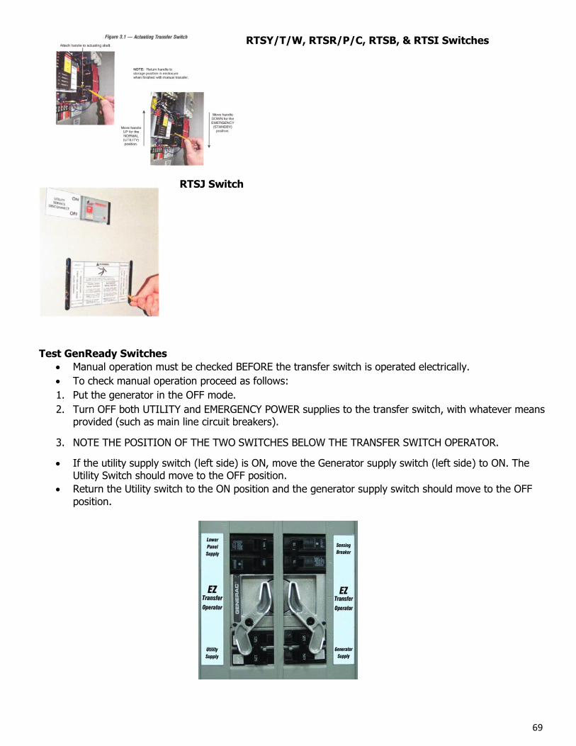
RTSY/T/W, RTSR/P/C, RTSB, & RTSI Switches
RTSJ Switch
Test GenReady Switches
Manual operation must be checked BEFORE the transfer switch is operated electrically.
To check manual operation proceed as follows:
1. Put the generator in the OFF mode.
2. Turn OFF both UTILITY and EMERGENCY POWER supplies to the transfer switch, with whatever means provided (such as main line circuit breakers).
3. NOTE THE POSITION OF THE TWO SWITCHES BELOW THE TRANSFER SWITCH OPERATOR.
If the utility supply switch (left side) is ON, move the Generator supply switch (left side) to ON. The Utility Switch should move to the OFF position.
Return the Utility switch to the ON position and the generator supply switch should move to the OFF
position.
70
Do Not send power to the house before Electrical checks/tests have been performed!
Voltage Checks
Turn ON the Utility power supply to the transfer switch using the Mainline circuit breaker (Utility Service Disconnect Breaker).
The RTG EZ switch may require the 2-pole transfer switch breaker in the main panel to be turned on
also.
DANGER - Proceed with Caution, the transfer switch is now electrically HOT. Contact with live
terminals results in extremely dangerous and possibly fatal electrical shock.
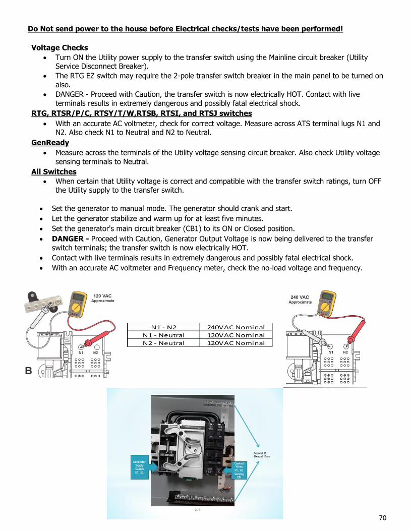
RTG, RTSR/P/C, RTSY/T/W,RTSB, RTSI, and RTSJ switches
With an accurate AC voltmeter, check for correct voltage. Measure across ATS terminal lugs N1 and N2. Also check N1 to Neutral and N2 to Neutral.
GenReady
Measure across the terminals of the Utility voltage sensing circuit breaker. Also check Utility voltage
sensing terminals to Neutral.
All Switches
When certain that Utility voltage is correct and compatible with the transfer switch ratings, turn OFF the Utility supply to the transfer switch.
Set the generator to manual mode. The generator should crank and start.
Let the generator stabilize and warm up for at least five minutes.
Set the generator's main circuit breaker (CB1) to its ON or Closed position.
DANGER - Proceed with Caution, Generator Output Voltage is now being delivered to the transfer
switch terminals; the transfer switch is now electrically HOT.
Contact with live terminals results in extremely dangerous and possibly fatal electrical shock.
With an accurate AC voltmeter and Frequency meter, check the no-load voltage and frequency.
71
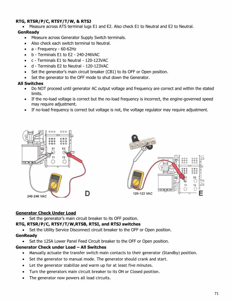
RTG, RTSR/P/C, RTSY/T/W, & RTSJ
Measure across ATS terminal lugs E1 and E2. Also check E1 to Neutral and E2 to Neutral.
GenReady
Measure across Generator Supply Switch terminals.
Also check each switch terminal to Neutral.
a - Frequency - 60-62Hz
b - Terminals E1 to E2 - 240-246VAC
c - Terminals E1 to Neutral - 120-123VAC
d - Terminals E2 to Neutral - 120-123VAC
Set the generator's main circuit breaker (CB1) to its OFF or Open position.
Set the generator to the OFF mode to shut down the Generator.
All Switches Do NOT proceed until generator AC output voltage and frequency are correct and within the stated
limits.
If the no-load voltage is correct but the no-load frequency is incorrect, the engine-governed speed
may require adjustment.
If no-load frequency is correct but voltage is not, the voltage regulator may require adjustment.
Generator Check Under Load
Set the generator’s main circuit breaker to its OFF position.
RTG, RTSR/P/C, RTSY/T/W,RTSB, RTSI, and RTSJ switches
Set the Utility Service Disconnect circuit breaker to the OFF or Open position.
GenReady
Set the 125A Lower Panel Feed Circuit breaker to the OFF or Open position.
Generator Check under Load – All Switches
Manually actuate the transfer switch main contacts to their generator (Standby) position.
Set the generator to manual mode. The generator should crank and start.
Let the generator stabilize and warm up for at least five minutes.
Turn the generators main circuit breaker to its ON or Closed position.
The generator now powers all load circuits.
72
DANGER - Proceed with Caution, Generator Output Voltage is now being delivered to the transfer switch terminals. The transfer switch is now electrically HOT. Contact with live terminals results in extremely dangerous and possibly fatal electrical shock.
Turn on electrical loads to the full rated wattage/amperage of the generator.
DO NOT OVERLOAD.
With the maximum rated load applied, check voltage and frequency across transfer switch terminals
E1 and E2.
Voltage should be greater than 230VAC and frequency should be greater than 59Hz.
Also verify the gas pressure remains within acceptable parameters.
Let the generator run the rated load at least 30 minutes.
With unit running, listen for unusual noises, vibration, overheating, etc.., that might indicate a
problem.
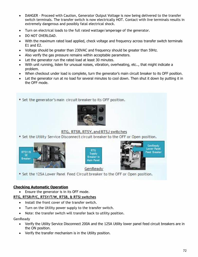
When checkout under load is complete, turn the generator’s main circuit breaker to its OFF position.
Let the generator run at no load for several minutes to cool down. Then shut it down by putting it in the OFF mode.
Checking Automatic Operation
Ensure the generator is in its OFF mode.
RTG, RTSR/P/C, RTSY/T/W, RTSB, & RTSI switches
Install the front cover of the transfer switch.
Turn on the Utility power supply to the transfer switch.
Note: the transfer switch will transfer back to utility position.
GenReady
Verify the Utility Service Disconnect 200A and the 125A Utility lower panel feed circuit breakers are in the ON position.
Verify the transfer mechanism is in the Utility position.
73
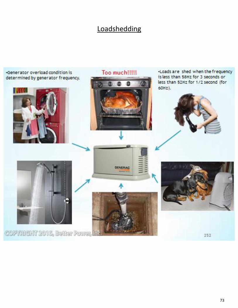
Loadshedding
74
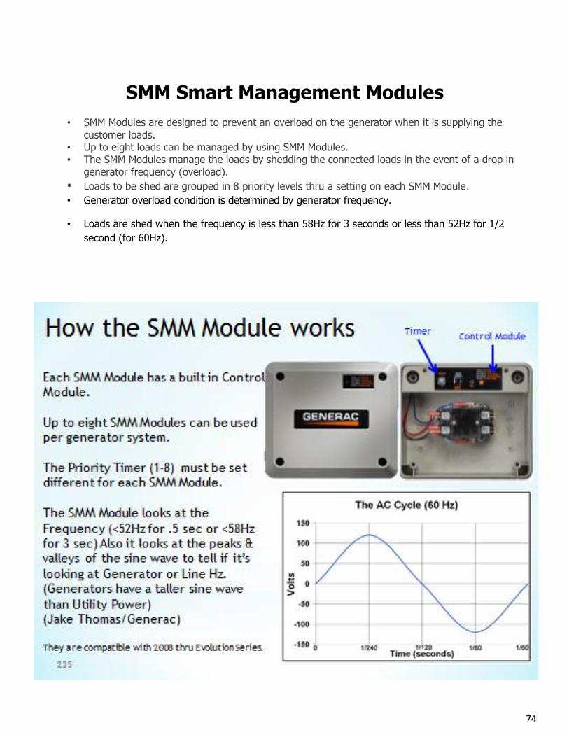
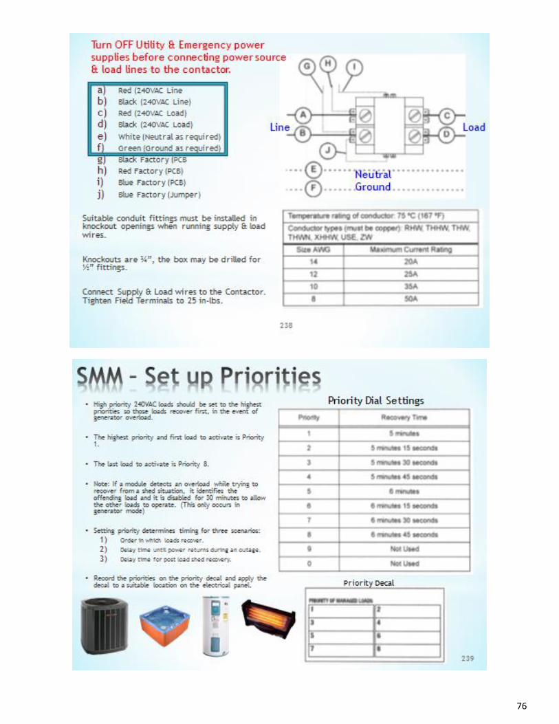
SMM Smart Management Modules
• SMM Modules are designed to prevent an overload on the generator when it is supplying the
customer loads. • Up to eight loads can be managed by using SMM Modules. • The SMM Modules manage the loads by shedding the connected loads in the event of a drop in
generator frequency (overload).
• Loads to be shed are grouped in 8 priority levels thru a setting on each SMM Module. • Generator overload condition is determined by generator frequency.
• Loads are shed when the frequency is less than 58Hz for 3 seconds or less than 52Hz for 1/2
second (for 60Hz).
75
76
77
78
79
80
81
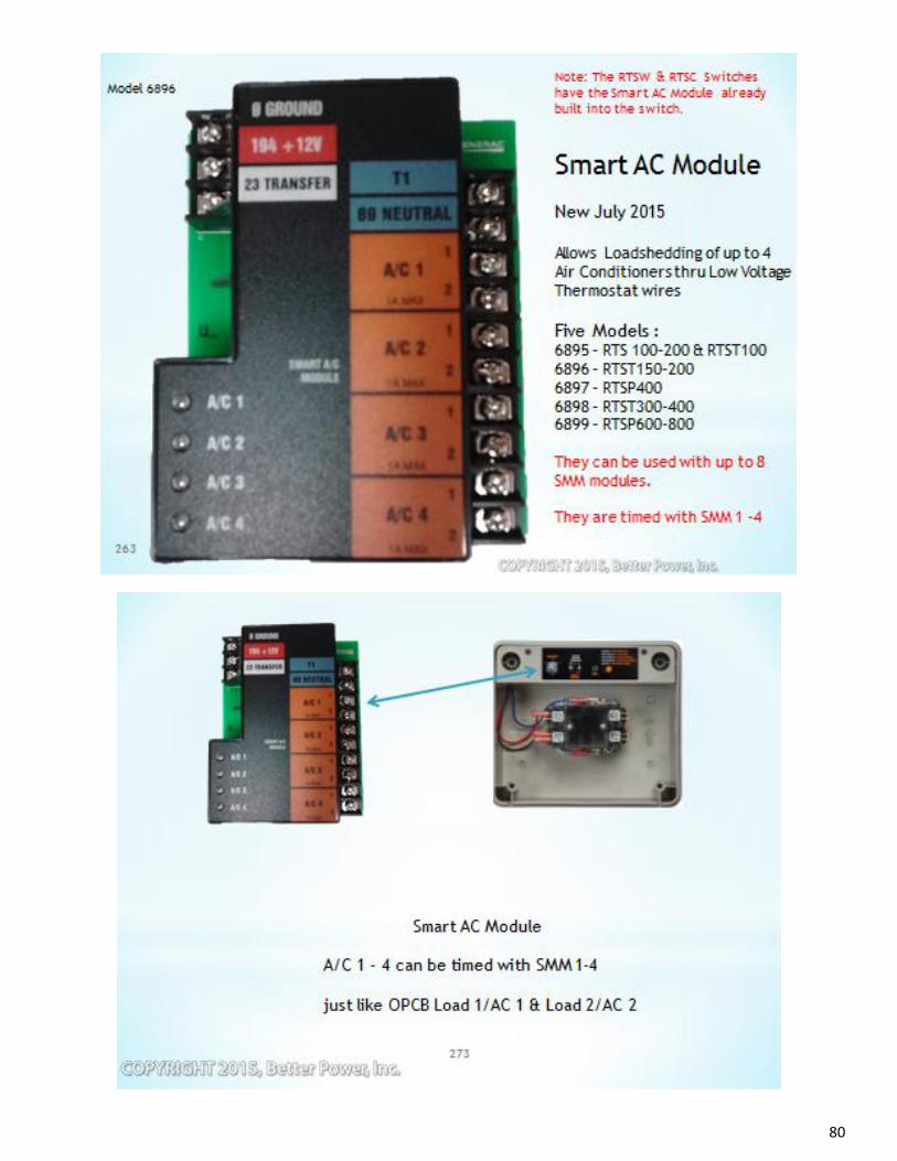
Load Shed Info and Wiring RTSY,RTSR, RTSB/RTSI There is NO Load Shedding in the RTST & RTSP Switches (there is a set of Aux. Contacts to lock out a load) RTSW & RTSC have the Smart AC Module to Loadshed up to four AC units. They install just like the OPCB Air
1 & Air 2. They will be priority 1, 2, 3, & 4. For 120/240v loads use the SMM Modules.
This Section can be found in the Owner’s Manual for Automatic Transfer Switch, pages 4 thru 6.
Also in Owner’s/Installation Manual Power Management Module (PMM) and Starter Kit.
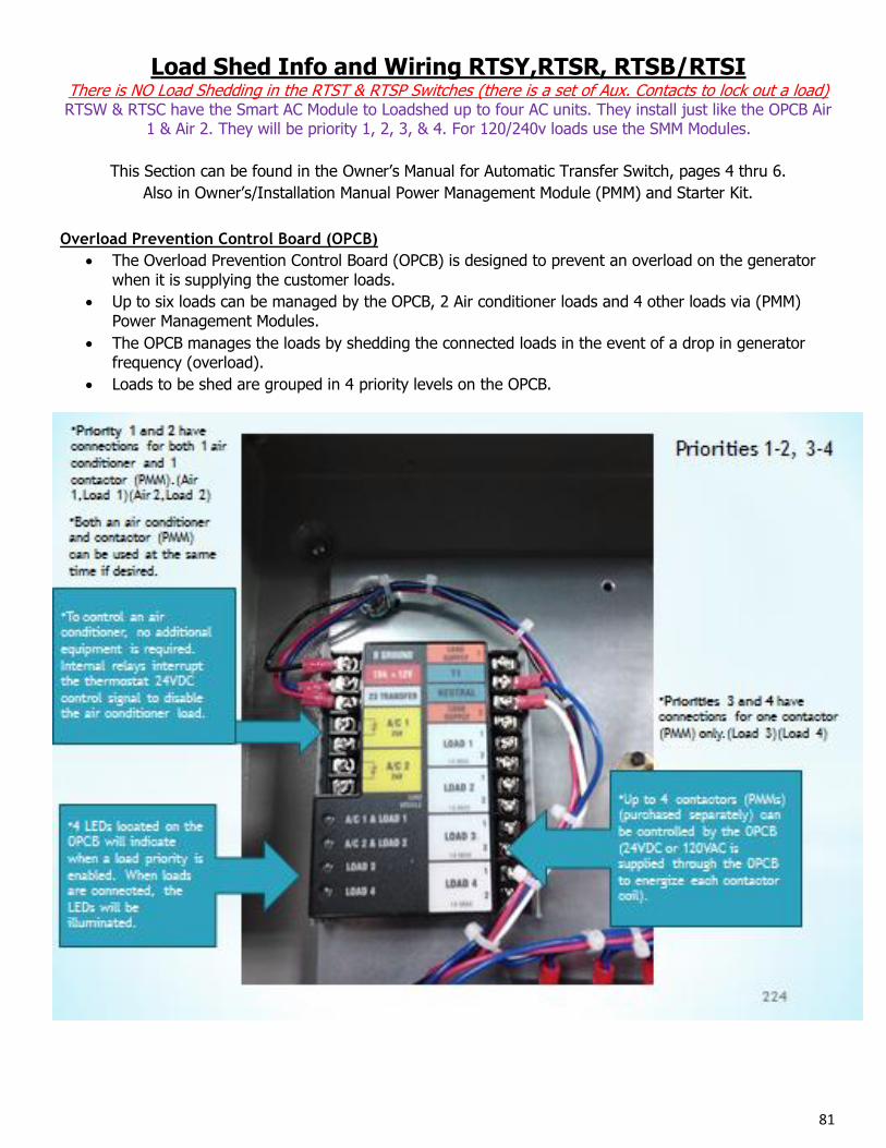
Overload Prevention Control Board (OPCB)
The Overload Prevention Control Board (OPCB) is designed to prevent an overload on the generator
when it is supplying the customer loads.
Up to six loads can be managed by the OPCB, 2 Air conditioner loads and 4 other loads via (PMM)
Power Management Modules.
The OPCB manages the loads by shedding the connected loads in the event of a drop in generator
frequency (overload).
Loads to be shed are grouped in 4 priority levels on the OPCB.
82
Priorities 1-2, 3-4
Priority 1 and 2 have connections for both 1 air conditioner and 1 contactor (PMM).
Both an air conditioner and contactor (PMM) can be used at the same time if desired.
To control an air conditioner, no additional equipment is required. Internal relays interrupt the thermostat 24VDC control signal to disable the air conditioner load.
Priorities 3 and 4 have connections for one contactor (PMM) only.
4 LEDs located on the OPCB will indicate when a load priority is enabled. When loads are connected, the LEDs will be illuminated.
Any loads including central air conditioners can be controlled via a contactor (PMM) that must be purchased separately.
Up to 4 contactors (PMMs) can be controlled by the OPCB (24VDC or 120VAC is supplied through the OPCB to energize each contactor coil).
Generator Overload Condition
Generator overload condition is determined by generator frequency.
Loads are shed when the frequency is less than 58Hz for 3 seconds or less than 50Hz for 1/2 second (for 60Hz).
The OPCB has a test button that forces the unit to act as if an overload has occurred.
This button operates even when the transfer signal is inactive.
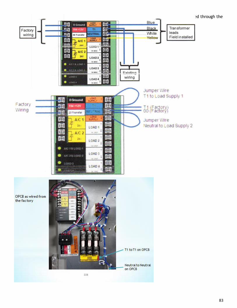
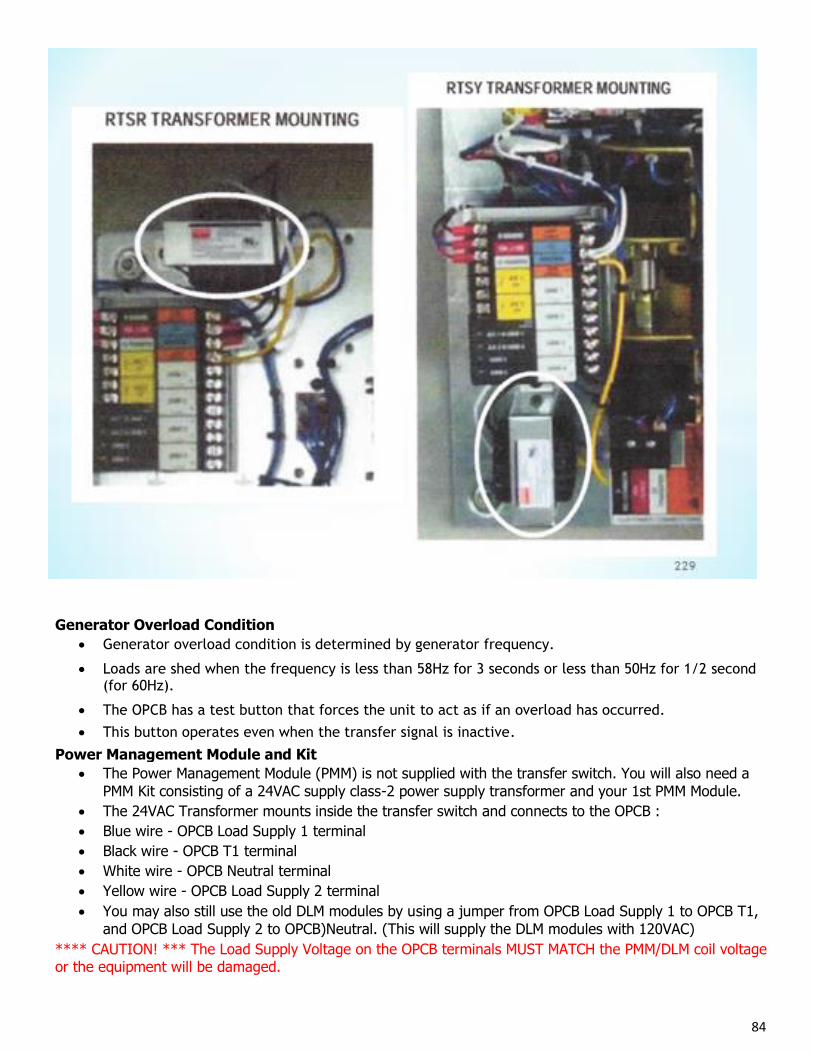
Power Management Module and Kit
The Power Management Module (PMM) is not supplied with the transfer switch. You will also need a
PMM Kit consisting of a 24VAC supply class-2 power supply transformer and your 1st PMM Module.
The 24VAC Transformer mounts inside the transfer switch and connects to the OPCB :
Blue wire - OPCB Load Supply 1 terminal
Black wire - OPCB T1 terminal
White wire - OPCB Neutral terminal
Yellow wire - OPCB Load Supply 2 terminal
You may also still use the old DLM modules by using a jumper from OPCB Load Supply 1 to OPCB T1, and OPCB Load Supply 2 to OPCB)Neutral. (This will supply the DLM modules with 120VAC)
**** CAUTION! *** The Load Supply Voltage on the OPCB terminals MUST MATCH the PMM/DLM coil voltage
or the equipment will be damaged.
Priorities 1-2, 3-4
Priority 1 and 2 have connections for both 1 air conditioner and 1 contactor (PMM).
Both an air conditioner and contactor (PMM) can be used at the same time if desired.
To control an air conditioner, no additional equipment is required. Internal relays interrupt the thermostat 24VDC control signal to disable the air conditioner load.
•Priorities 3 and 4 have connections for one contactor (PMM) only.
4 LEDs located on the OPCB will indicate when a load priority is enabled. When loads are connected, the LEDs will be illuminated.
Any loads including central air conditioners can be controlled via a contactor (PMM) that must be purchased separately.
83
Up to 4 contactors (PMMs) can be controlled by the OPCB (24VDC or 120VAC is supplied through the OPCB to energize each contactor coil).
84
Generator Overload Condition
Generator overload condition is determined by generator frequency.
Loads are shed when the frequency is less than 58Hz for 3 seconds or less than 50Hz for 1/2 second (for 60Hz).
The OPCB has a test button that forces the unit to act as if an overload has occurred.
This button operates even when the transfer signal is inactive.
Power Management Module and Kit
The Power Management Module (PMM) is not supplied with the transfer switch. You will also need a
PMM Kit consisting of a 24VAC supply class-2 power supply transformer and your 1st PMM Module.
The 24VAC Transformer mounts inside the transfer switch and connects to the OPCB :
Blue wire - OPCB Load Supply 1 terminal
Black wire - OPCB T1 terminal
White wire - OPCB Neutral terminal
Yellow wire - OPCB Load Supply 2 terminal
You may also still use the old DLM modules by using a jumper from OPCB Load Supply 1 to OPCB T1,
and OPCB Load Supply 2 to OPCB)Neutral. (This will supply the DLM modules with 120VAC)
**** CAUTION! *** The Load Supply Voltage on the OPCB terminals MUST MATCH the PMM/DLM coil voltage or the equipment will be damaged.
85
Air 1 and Air 2 OPCB terminals (A/C1, A/C2, A/C3, A/C4 on the Smart AC Module) Route the thermostat cable (from the furnace to the outside air conditioner unit) to the transfer
switch.
Route the cable away from High voltage wires.
Connect the wire to the upper terminal Air 1 on the OPCB. These are normally closed contacts which open upon load shed conditions.
From the lower terminal Air 1 route the wire back to the air conditioner unit.
If you are shedding two air conditioners do the same procedure using OPCB Air 2 for the second air
conditioner.
Contact ratings for Air 1 and 2 - 24VAC, 5.0Amps Max
Note: These instructions are for typical air conditioner installation. Control of a heat pump and 2-stage air conditioners will require special conditions or the use of a PMM/DLM module to control the loads.
Order of Load Shedding
Load 1 - 4 OPCB terminals
Determine the order of shedding for the loads to be connected to Load 1 thru 4 on the OPCB.
Load 1 is the highest priority and Load 4 is the lowest priority.
If connecting an existing (Hot) load, make sure the circuit breaker for the load is in the off position.
PMM/DLM Installation
Handle the PMM/DLM carefully. Do not drop or damage, protect against impact, construction grit and metal chips.
Install the PMM/DLM Module as close as possible to the load that is to be connected to it.
The PMM/DLM Module must be mounted on the back surface.
Indoor installation - The PMM/DLM Module can be mounted in any orientation that is convenient.
Outdoor installation - The PMM/DLM Module MUST be mounted with the drain hole on the bottom.
To prevent switch distortion, level all mounting points.
To maintain NEMA-3R rating, a suitable UL-listed-for wet-locations box connector must be used.
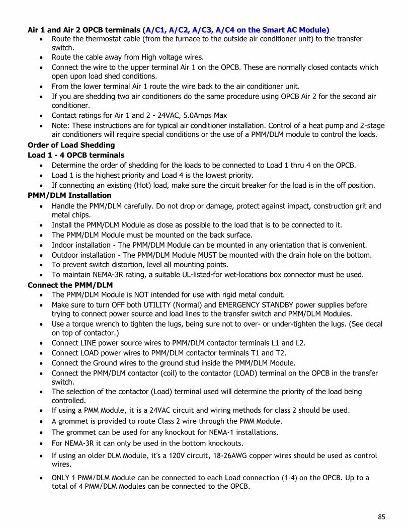
Connect the PMM/DLM
The PMM/DLM Module is NOT intended for use with rigid metal conduit.
Make sure to turn OFF both UTILITY (Normal) and EMERGENCY STANDBY power supplies before trying to connect power source and load lines to the transfer switch and PMM/DLM Modules.
Use a torque wrench to tighten the lugs, being sure not to over- or under-tighten the lugs. (See decal
on top of contactor.)
Connect LINE power source wires to PMM/DLM contactor terminals L1 and L2.
Connect LOAD power wires to PMM/DLM contactor terminals T1 and T2.
Connect the Ground wires to the ground stud inside the PMM/DLM Module.
Connect the PMM/DLM contactor (coil) to the contactor (LOAD) terminal on the OPCB in the transfer switch.
The selection of the contactor (Load) terminal used will determine the priority of the load being
controlled.
If using a PMM Module, it is a 24VAC circuit and wiring methods for class 2 should be used.
A grommet is provided to route Class 2 wire through the PMM Module.
The grommet can be used for any knockout for NEMA-1 installations.
For NEMA-3R it can only be used in the bottom knockouts.
If using an older DLM Module, it's a 120V circuit, 18-26AWG copper wires should be used as control wires.
ONLY 1 PMM/DLM Module can be connected to each Load connection (1-4) on the OPCB. Up to a total of 4 PMM/DLM Modules can be connected to the OPCB.
86
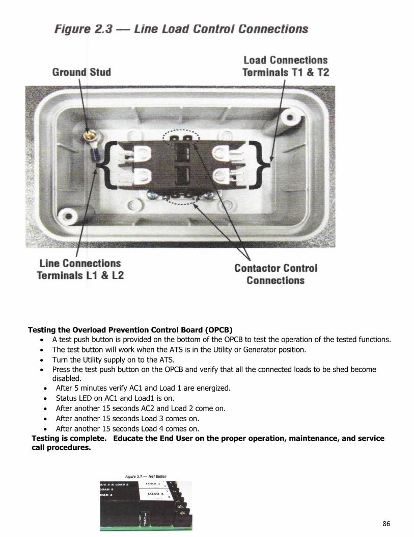
Testing the Overload Prevention Control Board (OPCB)
A test push button is provided on the bottom of the OPCB to test the operation of the tested functions.
The test button will work when the ATS is in the Utility or Generator position.
Turn the Utility supply on to the ATS.
Press the test push button on the OPCB and verify that all the connected loads to be shed become
disabled.
After 5 minutes verify AC1 and Load 1 are energized.
Status LED on AC1 and Load1 is on.
After another 15 seconds AC2 and Load 2 come on.
After another 15 seconds Load 3 comes on.
After another 15 seconds Load 4 comes on.
Testing is complete. Educate the End User on the proper operation, maintenance, and service
call procedures.
87
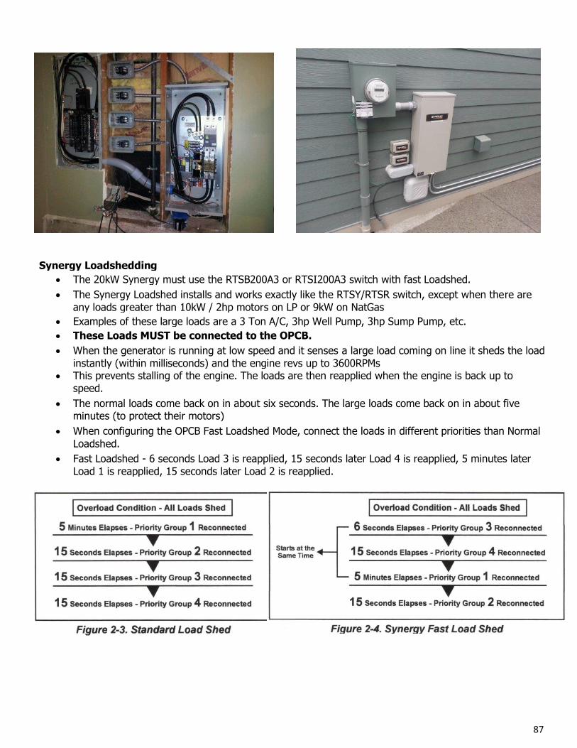
Synergy Loadshedding
The 20kW Synergy must use the RTSB200A3 or RTSI200A3 switch with fast Loadshed.
The Synergy Loadshed installs and works exactly like the RTSY/RTSR switch, except when there are
any loads greater than 10kW / 2hp motors on LP or 9kW on NatGas
Examples of these large loads are a 3 Ton A/C, 3hp Well Pump, 3hp Sump Pump, etc.
These Loads MUST be connected to the OPCB.
When the generator is running at low speed and it senses a large load coming on line it sheds the load
instantly (within milliseconds) and the engine revs up to 3600RPMs This prevents stalling of the engine. The loads are then reapplied when the engine is back up to
speed.
The normal loads come back on in about six seconds. The large loads come back on in about five minutes (to protect their motors)
When configuring the OPCB Fast Loadshed Mode, connect the loads in different priorities than Normal
Loadshed.
Fast Loadshed - 6 seconds Load 3 is reapplied, 15 seconds later Load 4 is reapplied, 5 minutes later
Load 1 is reapplied, 15 seconds later Load 2 is reapplied.
88
RTSJ Switch Only
Test Load Shed Function - Press the Load Shed Reset/Test pushbutton for more than 6 seconds on the outside of the ATS door.
Release the pushbutton when the Load shed switch actuates disconnecting the non-essential loads.
The Load Shed LED will light up.
The next step will depend on how the LSC is set up: Manual or Automatic Operation
Manual Operation - Press the door mounted LOAD SHED/RESET/TEST button for greater than 2 seconds.
Release the button when the LSS actuates, reconnecting the non-essential loads.
AUTOMATIC Operation - the LSS will reconnect non-essential loads after the delay setup on the DIP
switches of the LSC
With the generator running and loads powered by the generator AC output, turn ON the Utility power supply to the transfer switch.
After approximately 15 seconds the switch should transfer loads back to the Utility power source.
Approximately one minute after re-transfer, the engine should shut down.
The system is now set for fully automatic operation.
For Prolonged Outages
If the End User needs to turn off the generator to conserve fuel or perform maintenance during a prolonged outage, educate them on these simple steps.
To turn off the Generator while running in AUTO & online:
1. Turn OFF or Open the main Utility Disconnect.
2. Turn OFF or Open the Main Line Circuit Breaker on the generator.
3. Turn the generator off (Let run for a few minutes to cool down).
Note: Synergy - If the generator is to remain off for more than one hour with No Utility power present, wait
one hour for the internal fans to cool it down.
To turn the generator back on:
1. Put the generator back in AUTO and allow it to start and warm up for a few minutes.
2. Turn ON or Close the Main Line Circuit Breaker on the generator.
The system is now in Automatic mode.
The Main Utility Disconnect can be turned on or closed.
Install Accessories
This section can be found in :
Install the oil filter/battery heaters 0J6113 Rev D
Owner and Installation Manual Mobile Link
Instruction Manual Wireless Local Remote Monitor Model 006664-0
Service Information Bulletin SIB12-07-W-RTS (Brown-Out Kit)
89
6212 Cold Weather Kit
Do Not install until unit has completely cooled.
Set the generator to OFF. Remove 7.5A fuse and disconnect at the transfer switch any utility inputs to the unit.
Remove front panel, remove fasteners securing control panel cover and remover cover.
Disconnect the battery (Negative cable first) and remove battery.
Using a clean cloth clean the bottom of the battery and battery compartment to remove any dirt or oil.
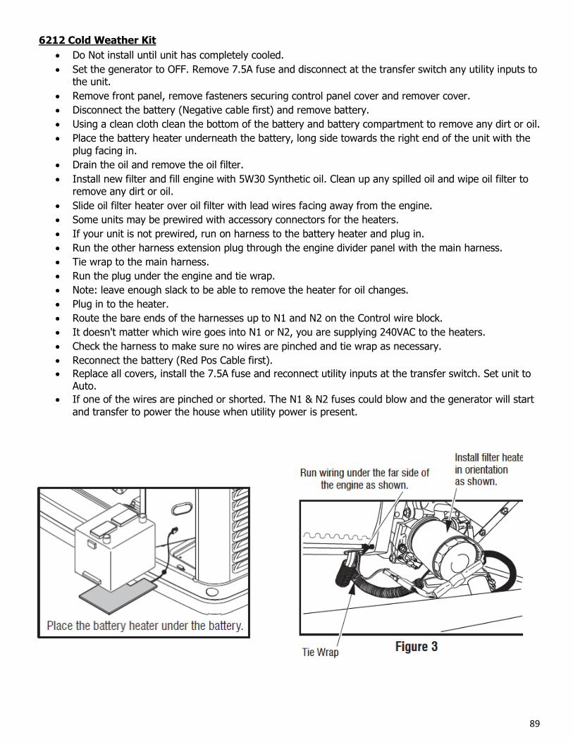
Place the battery heater underneath the battery, long side towards the right end of the unit with the
plug facing in.
Drain the oil and remove the oil filter.
Install new filter and fill engine with 5W30 Synthetic oil. Clean up any spilled oil and wipe oil filter to remove any dirt or oil.
Slide oil filter heater over oil filter with lead wires facing away from the engine.
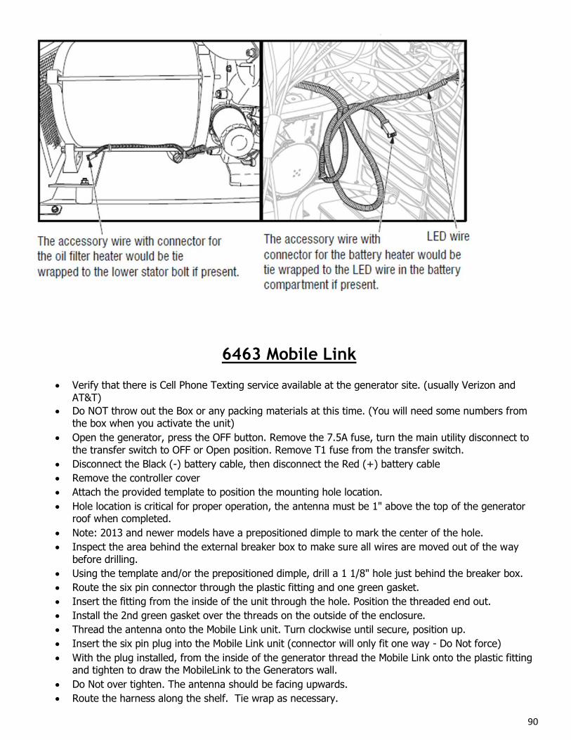
Some units may be prewired with accessory connectors for the heaters.
If your unit is not prewired, run on harness to the battery heater and plug in.
Run the other harness extension plug through the engine divider panel with the main harness.
Tie wrap to the main harness.
Run the plug under the engine and tie wrap.
Note: leave enough slack to be able to remove the heater for oil changes.
Plug in to the heater.
Route the bare ends of the harnesses up to N1 and N2 on the Control wire block.
It doesn't matter which wire goes into N1 or N2, you are supplying 240VAC to the heaters.
Check the harness to make sure no wires are pinched and tie wrap as necessary.
Reconnect the battery (Red Pos Cable first).
Replace all covers, install the 7.5A fuse and reconnect utility inputs at the transfer switch. Set unit to Auto.
If one of the wires are pinched or shorted. The N1 & N2 fuses could blow and the generator will start
and transfer to power the house when utility power is present.
90
6463 Mobile Link
Verify that there is Cell Phone Texting service available at the generator site. (usually Verizon and
AT&T)
Do NOT throw out the Box or any packing materials at this time. (You will need some numbers from the box when you activate the unit)
Open the generator, press the OFF button. Remove the 7.5A fuse, turn the main utility disconnect to
the transfer switch to OFF or Open position. Remove T1 fuse from the transfer switch.
Disconnect the Black (-) battery cable, then disconnect the Red (+) battery cable
Remove the controller cover
Attach the provided template to position the mounting hole location.
Hole location is critical for proper operation, the antenna must be 1" above the top of the generator roof when completed.
Note: 2013 and newer models have a prepositioned dimple to mark the center of the hole.
Inspect the area behind the external breaker box to make sure all wires are moved out of the way
before drilling.
Using the template and/or the prepositioned dimple, drill a 1 1/8" hole just behind the breaker box.
Route the six pin connector through the plastic fitting and one green gasket.
Insert the fitting from the inside of the unit through the hole. Position the threaded end out.
Install the 2nd green gasket over the threads on the outside of the enclosure.
Thread the antenna onto the Mobile Link unit. Turn clockwise until secure, position up.
Insert the six pin plug into the Mobile Link unit (connector will only fit one way - Do Not force)
With the plug installed, from the inside of the generator thread the Mobile Link onto the plastic fitting and tighten to draw the MobileLink to the Generators wall.
Do Not over tighten. The antenna should be facing upwards.
Route the harness along the shelf. Tie wrap as necessary.
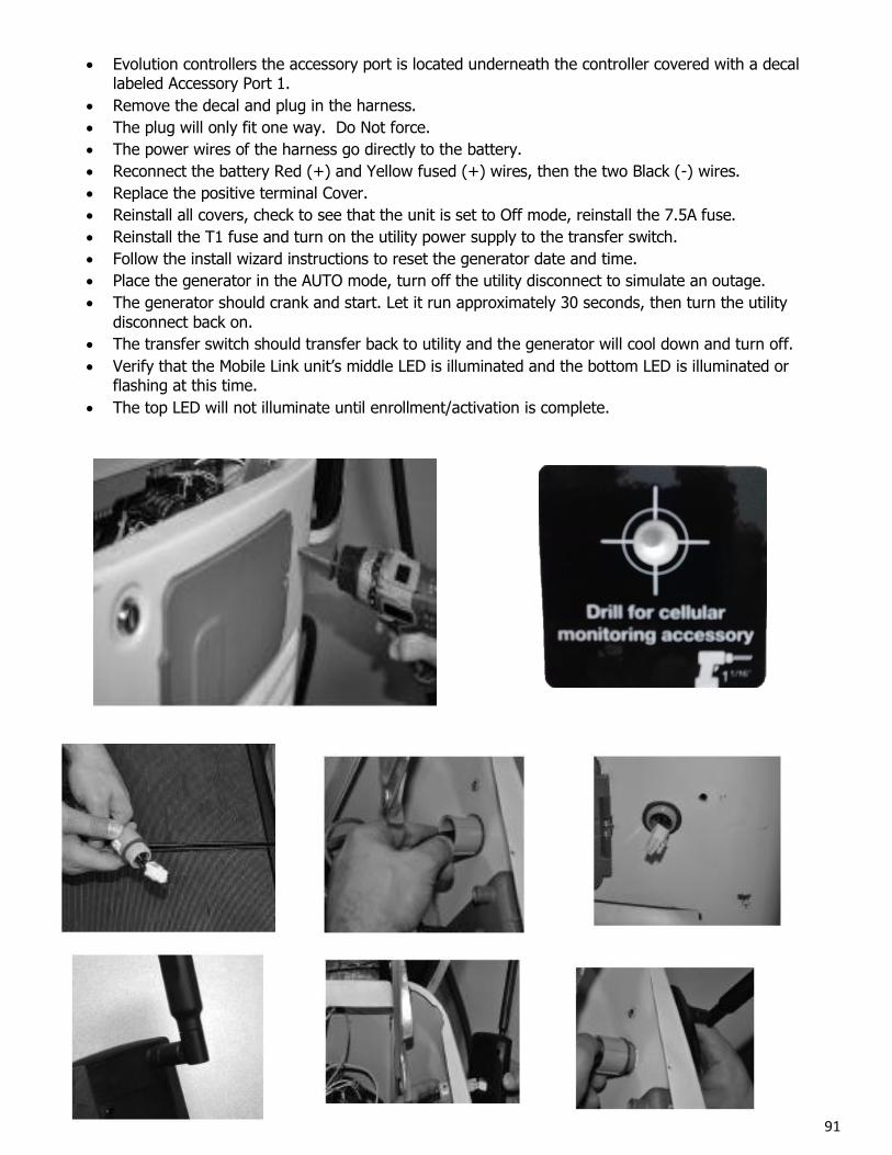
91
Evolution controllers the accessory port is located underneath the controller covered with a decal labeled Accessory Port 1.
Remove the decal and plug in the harness.
The plug will only fit one way. Do Not force.
The power wires of the harness go directly to the battery.
Reconnect the battery Red (+) and Yellow fused (+) wires, then the two Black (-) wires.
Replace the positive terminal Cover.
Reinstall all covers, check to see that the unit is set to Off mode, reinstall the 7.5A fuse.
Reinstall the T1 fuse and turn on the utility power supply to the transfer switch.
Follow the install wizard instructions to reset the generator date and time.
Place the generator in the AUTO mode, turn off the utility disconnect to simulate an outage.
The generator should crank and start. Let it run approximately 30 seconds, then turn the utility
disconnect back on.
The transfer switch should transfer back to utility and the generator will cool down and turn off.
Verify that the Mobile Link unit’s middle LED is illuminated and the bottom LED is illuminated or flashing at this time.
The top LED will not illuminate until enrollment/activation is complete.
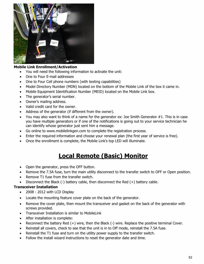
92
Mobile Link Enrollment/Activation
You will need the following information to activate the unit:
One to Four E-mail addresses
One to Four Cell phone numbers (with texting capabilities)
Model Directory Number (MDN) located on the bottom of the Mobile Link of the box it came in.
Mobile Equipment Identification Number (MEID) located on the Mobile Link box.
The generator’s serial number.
Owner’s mailing address.
Valid credit card for the owner.
Address of the generator (if different from the owner).
You may also want to think of a name for the generator ex: Joe Smith Generator #1. This is in case
you have multiple generators or if one of the notifications is going out to your service technician he can identify whose generator just sent him a message.
Go online to www.mobilelinkgen.com to complete the registration process.
Enter the required information and choose your renewal plan (the first year of service is free).
Once the enrollment is complete, the Mobile Link’s top LED will illuminate.
Local Remote (Basic) Monitor
Open the generator, press the OFF button.
Remove the 7.5A fuse, turn the main utility disconnect to the transfer switch to OFF or Open position.
Remove T1 fuse from the transfer switch.
Disconnect the Black (-) battery cable, then disconnect the Red (+) battery cable.
Transceiver Installation
2008 - 2012 with LCD Display
Locate the mounting feature cover plate on the back of the generator.
Remove the cover plate, then mount the transceiver and gasket on the back of the generator with
screws provided.
Transceiver Installation is similar to MobileLink
After installation is complete:
Reconnect the battery Red (+) wire, then the Black (-) wire. Replace the positive terminal Cover.
Reinstall all covers, check to see that the unit is in to Off mode, reinstall the 7.5A fuse.
Reinstall the T1 fuse and turn on the utility power supply to the transfer switch.
Follow the install wizard instructions to reset the generator date and time.
93
Display unit installation
Install two AAA non-rechargeable alkaline batteries in the display unit. (The expected life of the batteries is six months.)
There is no power switch; the monitor will power up when the batteries are inserted.
Low Battery Indicator
The battery status indicator will flash every 5 seconds and the buzzer will sound every 15 minutes
when a low battery is detected.
The buzzer may be silenced by briefly pressing and releasing the test button (after the buzzer has sounded).
The buzzer will pulse twice to indicate it has been silenced and will not reactivate until a new alarm is
detected.
Note: Batteries should be changed when the battery low indicator warning is activated.
Signal Strength Test
The signal strength test should be performed from the intended mounting location.
The Green, Yellow, and Red lights will alternately flash for a short period.
The unit will be in test mode for 30 seconds
Green - Good signal strength
Yellow - Marginal Signal Strength
Red - No Signal
After 30 Seconds the unit will exit test mode, the lights will alternately light, and the unit will be in Status mode.
Note: Extended use of the Signal Strength Test may deplete battery life.
The display unit will work if the signal strength is marginal (Yellow), but battery life may be reduced.
The display unit is intended to be mounted indoors.
Avoid mounting in a wet or damp area.
The unit can be desk, wall, or magnet mounted.
Operation
The normal state of the display will have No lights active. This indicates the generator has no problems.
Generator Transceiver Status Light - The transceiver has a Green light that indicates it has power and is
communicating with the display unit.
Display Unit Green Light - The Green light will flash every 5 seconds when the generator is running.
To verify the status of the generator when Not running, press the test button
If the generator is in AUTO and there are no Alarms or Warnings present the green light will illuminate.
Display Unit Yellow Light - Indicates a generator warning is present or the generator needs maintenance.
When active and not running the Yellow light will flash once every 5 seconds.
When running the green light will be on and the yellow light will flash every 5 seconds.
The internal buzzer will sound once every 4 hours for 1 second.
The buzzer may be silenced by briefly pressing and releasing the test button (after the buzzer has sounded).
The buzzer will pulse twice to indicate it has been silenced and will not reactivate until a new alarm is
detected.
Display Unit Red Light - Indicates the Auto/Off/Manual button is in the OFF mode, or a generator alarm is present.
If an alarm is present check the generator status and call a certified repair dealer if necessary.

94
The generator will not start or will be shut down if already running.
The Red light will flash every 5 seconds.
The internal buzzer will sound once every 5 seconds.
The buzzer may be silenced by briefly pressing and releasing the test button (after the buzzer has sounded).
The buzzer will pulse twice to indicate it has been silenced and will not reactivate until a new alarm is
detected.
6424 Utility Voltage Monitor Timer (Brownout Kit)
Place the generator in the OFF mode, open the circuit breaker on the generator. De-energize the
utility power to the transfer switch.
Use the relay socket to mark the mounting hole locations, and drill two M3.6 holes. Mount the socket
using two Taptite screws and flat washers.
Ensure the keyway in the center of the socket is facing the bottom of the enclosure. This causes the
writing on the VM relay to be face up when the installation is complete.
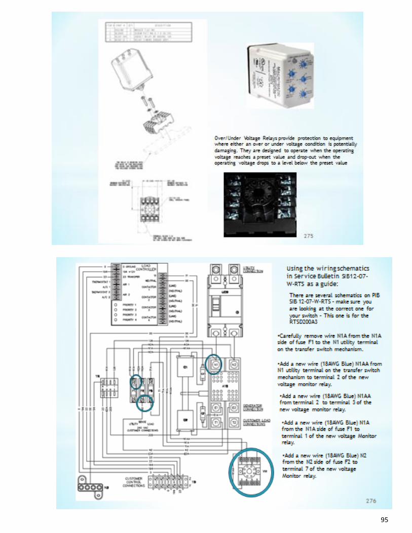
95
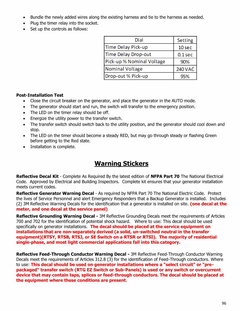
96
Bundle the newly added wires along the existing harness and tie to the harness as needed.
Plug the timer relay into the socket.
Set up the controls as follows:
Post-Installation Test
Close the circuit breaker on the generator, and place the generator in the AUTO mode.
The generator should start and run, the switch will transfer to the emergency position.
The LED on the timer relay should be off.
Energize the utility power to the transfer switch.
The transfer switch should switch back to the utility position, and the generator should cool down and
stop.
The LED on the timer should become a steady RED, but may go through steady or flashing Green
before getting to the Red state.
Installation is complete.
Warning Stickers
Reflective Decal Kit - Complete As Required By the latest edition of NFPA Part 70 The National Electrical
Code. Approved by Electrical and Building Inspectors. Complete kit ensures that your generator installation meets current codes.
Reflective Generator Warning Decal - As required by NFPA Part 70 The National Electric Code. Protect
the lives of Service Personnel and alert Emergency Responders that a Backup Generator is installed. Includes (2) 3M Reflective Warning Decals for the identification that a generator is installed on site. (one decal at the
meter, and one decal at the service panel)
Reflective Grounding Warning Decal - 3M Reflective Grounding Decals meet the requirements of Articles
700 and 702 for the identification of potential shock hazard. Where to use: This decal should be used specifically on generator installations. The decal should be placed at the service equipment on installations that are non-separately derived (a solid, un-switched neutral in the transfer
equipment)(RTSY, RTSB, RTSJ, or SE Switch on a RTSR or RTSI). The majority of residential single-phase, and most light commercial applications fall into this category.
Reflective Feed-Through Conductor Warning Decal - 3M Reflective Feed-Through Conductor Warning Decals meet the requirements of Articles 312.8 (3) for the identification of Feed-Through conductors. Where to use: This decal should be used on generator installations where a "select circuit" or "pre-
packaged" transfer switch (RTG EZ Switch or Sub-Panels) is used or any switch or overcurrent device that may contain taps, splices or feed-through conductors. The decal should be placed at
the equipment where these conditions are present.
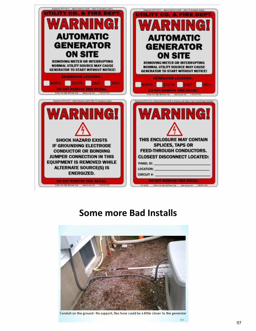
97
Some more Bad Installs
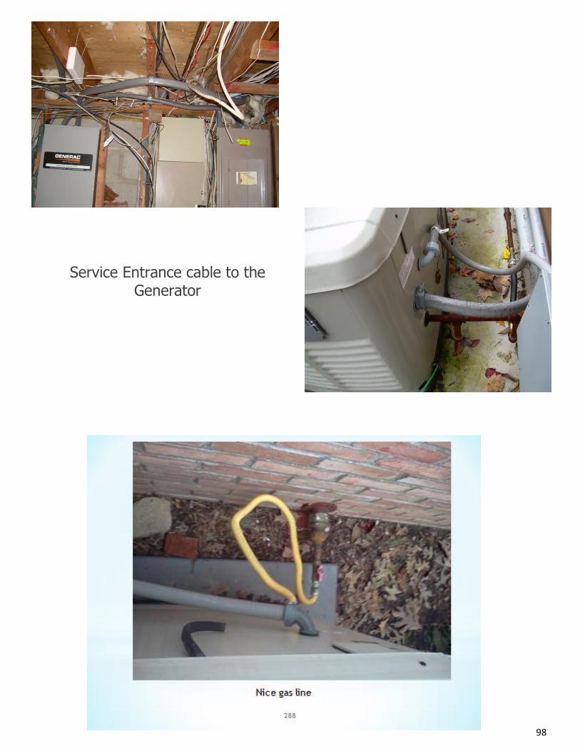
98
Service Entrance cable to the Generator
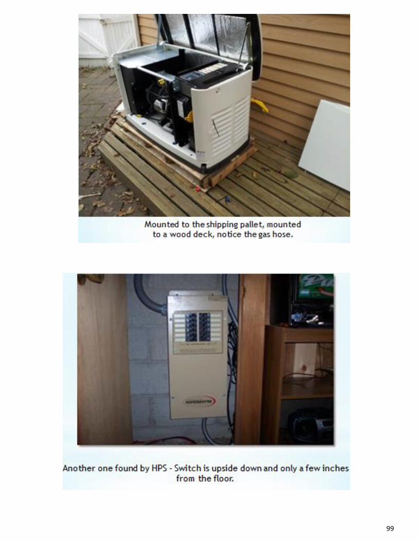
99
100
We hope this information will help make your installs safe, easy, and your customers Happy.
Also Available from Generac & Better Power
QT/RG Series - Liquid-cooled GenSets 22kW - 150kW Single & Three Phase
RD Protector Series - Diesel GenSets 15kW - 50kW Single & Three Phase
Generac iX, iQ, GP, LP, XG, & XP Series, DeWalt, & Powermate - Portable Gasoline,
Propane, & Diesel Generators
Generac/GenTran Manual Transfer Switches - For Portable generators
Generac Residential, Commercial, Industrial Series - Pressure Washers, & Pumps
Generac Industrial - Gaseous & Diesel GenSets
Generac/Magnum Towable Generators, Light Towers, & Diaphragm Pumps
Related Documents