Welcome message from author
This document is posted to help you gain knowledge. Please leave a comment to let me know what you think about it! Share it to your friends and learn new things together.
Transcript
North Western Railway Jaipur
Rly (O). 44550, BSNL (0). TelFAX: 0145-2429498 E-mail: N.S Patiyal, Director, STC Ajmer
[email protected] Mob: 9001196582
AT
INDEX CARRIAGE & WAGON THEORY (MCT-02)
S. No. Description Page No.
From To
1
Wagon & its Main Parts Underframe Body Bogie Brake Rigging CBC Assembly
1 9
2
Design Features of Various Wagons Classification of Wagons Transportation & Mechanical codes Types of wagons
10 20
3 Stainless Steel Wagons, Aluminium Wagons, Higher Axle Load Wagons
21 26
4
New Pattern of Train Examination of Goods Stock End to End Examination Premium Rake CC Rake
27 31
5 Wagon Manufacturing - Use of Huck/Lock bolts 32 32 6 Over Dimensional Consignment 33 35 7 IRCA Part III 36 38
8 Container Wagons- BLC Train Operation and Maintenance Practice
39 43
9
Repair & Maintenance of Goods Stock – ROH ROH of CASNUB Bogie Condemnation of Wagons ROH/POH interval of Wagon Stock ROH of BLC wagons List of Must Change Items During ROH Performa for BTPN ROH
44 58
10 Tank Wagons - Repairs & Maintenance 59 63 11 Air Brake System in Wagons 64 67 12 Bogie Mounted Brake System (BMBS) 68 69 13 Brake Binding - Causes & Remedies 70 72 14 Train Parting - Causes & Remedies 73 77 15 Accident Relief Train 78 81 16 ART/MFD/SPART/140T Crane Maintenance 82 84 17 Derailment Mechanism 85 87 18 Accident, Investigation, CRS Inquiry 88 98 19 Disaster Management - Role of Supervisors 99 102
20 Role of Supervisors to minimize sick figures/coach detachment/ineffective %
103 104
21 Marshalling of trains 105 107 22 Wheel Impact Load Detector (WILD) 108 111 23 Weigh bridge 112 114
24 Layout of Coaching & goods stock yard and its infrastructural facilities
115 117
1
WAGON MAIN PARTS OF WAGON
Under frame Body Bogie Brake Rigging CBC Assembly
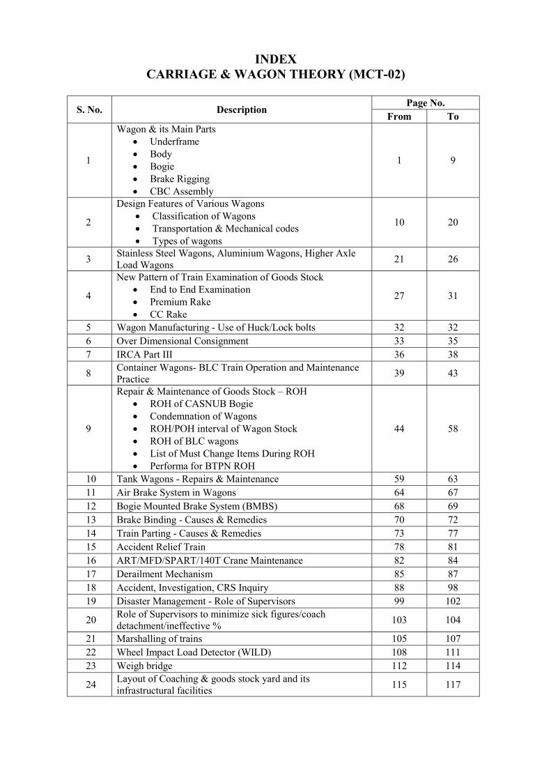
UNDER FRAME The type and size of a particular under frame is intimately related to the type and design of a wagon, as it constitutes the main load bearing sub-assembly for the vehicle. The overall dimensions and design of this structure take into account the quantum and pattern of loading on the vehicles as well as the track considerations. This in turn determines the permissible wheel base and whether a four wheeler or a bogie wagon would be required for the purpose of carrying the required load. Accordingly, while designing an under frame, the loading per meter is also taken into account as this is to be permitted by the type of track available. The buffing and impact loads also govern the strength of the under frame and the shunting speeds permitted for the marshalling of the goods stock. In the case of bogie wagons, the load transfer to the bogie frame is by means of pivot arrangement and thus the bogie frame is by means of pivot arrangement and thus the bogie frame also assumes an equally important function. GENERAL CONSTRUCTION OF BG WAGON UNDER FRAME The main members of a typical conventional BG wagon under frame are as under:
i. Sole bars ii. Head Stock iii. Longitudinal channels iv. Cross bars v Diagonal channels vi Floor vii. Crib angle viii End angle ix Gusset plates x. Centre pivot xi. Transom
The main under frame of a vehicle generally consists of two outer longitudinal members viz. Sole bars and the two head stocks which are strengthened by two middle longitudinal and various cross members. The diagonals and gusset plates protect the under frame against diagonal deflection and help in absorbing and distributing the buffing loads over different members. As already mentioned, the gusset plates and knees are provided at critical locations to impart additional strength to the joints. The whole structure is so designed that various loads are uniformly distributed and no single member has to bear excessive load than designed for.
Various rolled sections are used for the under frame members. Channel sections are generally used for headstock and sole bars for facilitating fitment of axle guards and buffers and Z-Sections are used for centre sills. Welding is generally used for joining the under frame members. But in earlier wagons, riveting had been used for joining these members. In the case of bogie wagons, the under frame has comparatively stronger cross members, known as bolsters. For fitting the upper centre pivot casting, which rests on the bogie pivot?
The under frame and all its members are necessarily to be true and square and these should conform to the manufacturing tolerances. All under frames are given an initial camber at the time of manufacture so that under actual loading conditions, these do not sag.
The under frame is main load bearing member in the vehicle which is not only subjected to static loads but also dynamic impacts owing to the unevenness in the track. In addition to this, it has to successfully withstand heavy buffing impacts during the course of marshalling as well as heavy jerks have to be sustained by the draw gear at the time of starting of goods trains. Hence in order to ensure safe and smooth running of vehicles, the maintenance of under frame has to be done very carefully.
It is therefore the duty of all supervisors both in workshops and divisions, to ensure that a thorough inspection of under frame is carried is carried out at the time of POH. Other major repairs and all defects and deficiencies that come to notice must be given meticulous and thorough attention. The defects and deficiencies generally noticed together with recommended repair practices have been carried out.
2
WAGON BODY
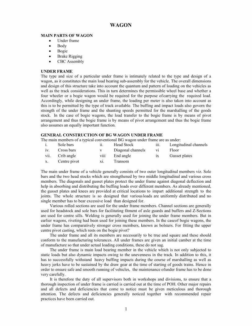
The superstructure attached to the under frame of wagon is called wagon body. It consists of body side and ends with their supporting structures such as stanchions, copings, roof structures, carlines; roof sheets in the case of covered wagons; hoppers and their supporting members in case of hopper wagons; tank barrels, cladding, if any, and supporting saddles in the case of tank wagons. Doors, door fittings, louvers for ventilation and various fittings such as cleats, handles, hooks, footsteps, hand brake wheel and ladders also form part of the body. GENERAL CONSTRUCTION OF OPEN WAGON Sides : Sides are made up of side panels and side stanchions, which are attached to the under frame by crib angles, riveting strips or welding and side stanchions, they include top copings, intermediate copings if any, doors, door fittings, hand holds, tarpaulin cleats and label holder. Ends: Ends are similar in construction to sides in that they consist of end panels, end stanchions, top copings and in some cases end shut stiffener, ventilator and intermediate copping. Attachment to the under frame is by means of end floor angles and through the stanchions. Corner stanchions connect the ends with the sides. Open wagons have reinforcing angles at each end together with reinforcing gussets and corner pressings at the corner. Doors: Each side of the wagon is provided with door for manual unloading. The doors are hinged at the bottom with locking arrangement by chainless cotter at the top. In BOXN wagons two extra locking bolts per door have also been provided to avoid slipping of chainless cotter during tippling of wagon. GENERAL CONSTRUCTION OF COVERED WAGON Sides: Sides are made up of side panels and side stanchions, which are attached to the under frame by crib angles, riveting strip/ Welding strips. They include top copings, doors, door fittings, and label holders, rain protection angles above swing doors, door striking plates and anti-bleeding device below the flap doors. Cattle wagons are also fitted with side louvers, breast bar fittings and wainscot boards. Ends: Ends are similar in construction to sides in that they consist of end panels, end stanchions, top copings and in some cases intermediate copping. Attachment to the under frame is by means of end floor angles and through the stanchions. Covered wagons are provided with ventilators at the upper end of body ends. Corner stanchions connect the ends with the sides. Ends of cattle wagons include wainscot boards. Roof: Roofs of covered wagons consist of roof sheets and carlines. Roof sheet are much thinner than the sheets used for the body sides and end panels. Door: Each side of the wagon is provided with door for manual unloading. The doors consist of swing doors at the top with label holder hinged to the angles on the sides and flap doors at the bottom, hinged at the bottom with Anti bleeding device.
BOGIE: CASNUB BOGIE
Cast Steel CASNUB Bogies comprise of two cast side frames and a floating bolster. The side-frames are connected by a fabricated mild steel spring plank to maintain the
bogie square. The bolster is supported on the side-frames through two groups of snubber springs, which
also incorporate the load proportional friction damping.

3
Bogie General Arrangement
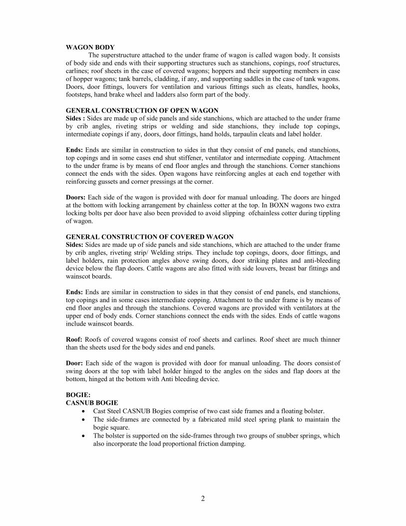
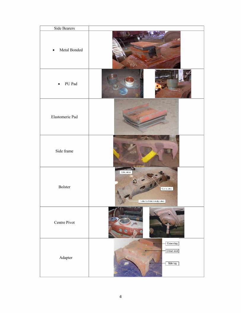
The CASNUB bogie assembly consists of the following components:
Wheel set with Cartridge Bearing Axle Box/ adapter, retainer bolt & side frame key assembly Side frames with friction plates and brake wear plates Bolster with wear liners Spring plank, fit bolts & rivets Load bearing springs and snubber springs Friction shoe wedges Centre pivot arrangement comprising of Centre pivot top, Centre pivot Bottom, Centre
pivot pin, Centre pivot retainer & locking arrangement Side Bearers Elastomeric Pad Bogie Brake Gear Brake Beam
4
Side Bearers
Metal Bonded
PU Pad
Elastomeric Pad
Side frame
Bolster
Centre Pivot
Adapter
5
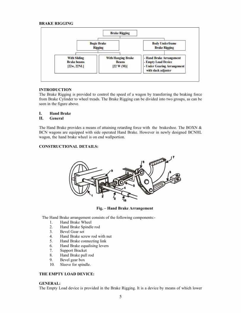
BRAKE RIGGING
INTRODUCTION The Brake Rigging is provided to control the speed of a wagon by transferring the braking force from Brake Cylinder to wheel treads. The Brake Rigging can be divided into two groups, as can be seen in the figure above. I. Hand Brake II. General
The Hand Brake provides a means of attaining retarding force with the brake shoe. The BOXN & BCN wagons are equipped with side operated Hand Brake. However in newly designed BCNHL wagon, the hand brake wheel is on end wall portion. CONSTRUCTIONAL DETAILS:
Fig. – Hand Brake Arrangement
The Hand Brake arrangement consists of the following components:-
1. Hand Brake Wheel 2. Hand Brake Spindle rod 3. Bevel Gear set 4. Hand Brake screw rod with nut 5. Hand Brake connecting link 6. Hand Brake equalising levers 7. Support Bracket 8. Hand Brake pull rod 9. Bevel gear box 10. Sleeve for spindle.
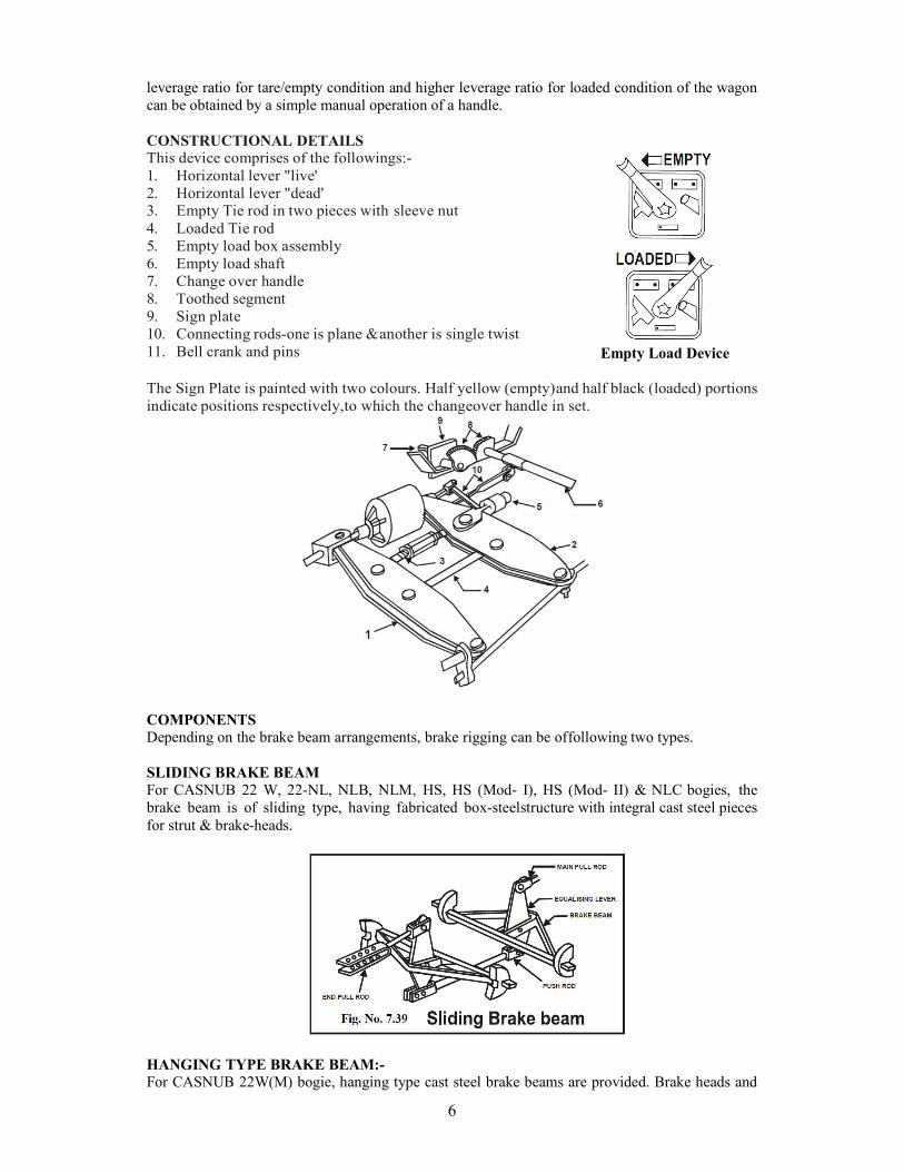
THE EMPTY LOAD DEVICE: GENERAL: The Empty Load device is provided in the Brake Rigging. It is a device by means of which lower
6
leverage ratio for tare/empty condition and higher leverage ratio for loaded condition of the wagon can be obtained by a simple manual operation of a handle. CONSTRUCTIONAL DETAILS This device comprises of the followings:- 1. Horizontal lever "live' 2. Horizontal lever "dead' 3. Empty Tie rod in two pieces with sleeve nut 4. Loaded Tie rod 5. Empty load box assembly 6. Empty load shaft 7. Change over handle 8. Toothed segment 9. Sign plate 10. Connecting rods-one is plane & another is single twist 11. Bell crank and pins
Empty Load Device
The Sign Plate is painted with two colours. Half yellow (empty) and half black (loaded) portions indicate positions respectively, to which the changeover handle in set.
COMPONENTS
Depending on the brake beam arrangements, brake rigging can be of following two types.
SLIDING BRAKE BEAM For CASNUB 22 W, 22-NL, NLB, NLM, HS, HS (Mod- I), HS (Mod- II) & NLC bogies, the brake beam is of sliding type, having fabricated box-steel structure with integral cast steel pieces for strut & brake-heads.
HANGING TYPE BRAKE BEAM:- For CASNUB 22W(M) bogie, hanging type cast steel brake beams are provided. Brake heads and
7
blocks are secured by key and they are further assembled with brake beams through spring loaded brake shoe adjuster.
Fig. - Hanging brake beam without additional brake beam support.
Fig. - Hanging brake beam with additional brake beam support.
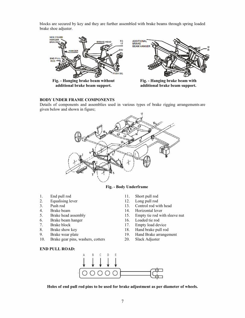
BODY UNDER FRAME COMPONENTS Details of components and assemblies used in various types of brake rigging arrangements are given below and shown in figure;
Fig. - Body Underframe
1. End pull rod 2. Equalising lever 3. Push rod 4. Brake beam 5. Brake head assembly 6. Brake beam hanger 7. Brake block 8. Brake show key 9. Brake wear plate 10. Brake gear pins, washers, cotters
11. Short pull rod 12. Long pull rod 13. Control rod with head 14. Horizontal lever 15. Empty tie rod with sleeve nut 16. Loaded tie rod 17. Empty load device 18. Hand brake pull rod 19. Hand Brake arrangement 20. Slack Adjuster
END PULL ROAD:
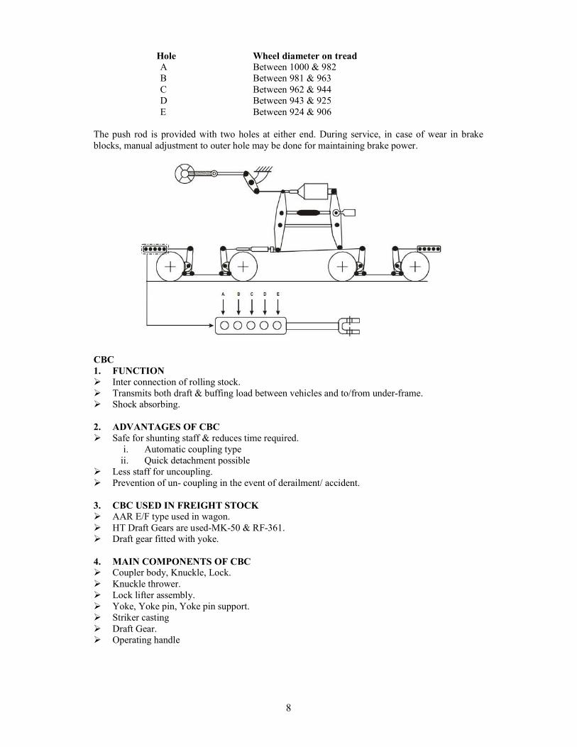
Holes of end pull rod pins to be used for brake adjustment as per diameter of wheels.
8
Hole Wheel diameter on tread A Between 1000 & 982 B Between 981 & 963 C Between 962 & 944 D Between 943 & 925 E Between 924 & 906
The push rod is provided with two holes at either end. During service, in case of wear in brake blocks, manual adjustment to outer hole may be done for maintaining brake power.
CBC 1. FUNCTION Inter connection of rolling stock. Transmits both draft & buffing load between vehicles and to/from under-frame. Shock absorbing. 2. ADVANTAGES OF CBC Safe for shunting staff & reduces time required.
i. Automatic coupling type ii. Quick detachment possible
Less staff for uncoupling. Prevention of un- coupling in the event of derailment/ accident.
3. CBC USED IN FREIGHT STOCK AAR E/F type used in wagon. HT Draft Gears are used-MK-50 & RF-361. Draft gear fitted with yoke.
4. MAIN COMPONENTS OF CBC Coupler body, Knuckle, Lock. Knuckle thrower. Lock lifter assembly. Yoke, Yoke pin, Yoke pin support. Striker casting Draft Gear. Operating handle
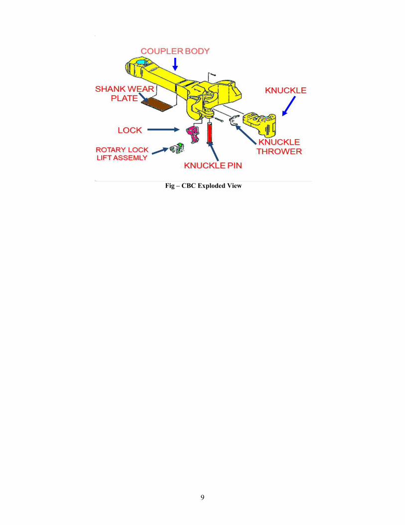
9
Fig – CBC Exploded View
10
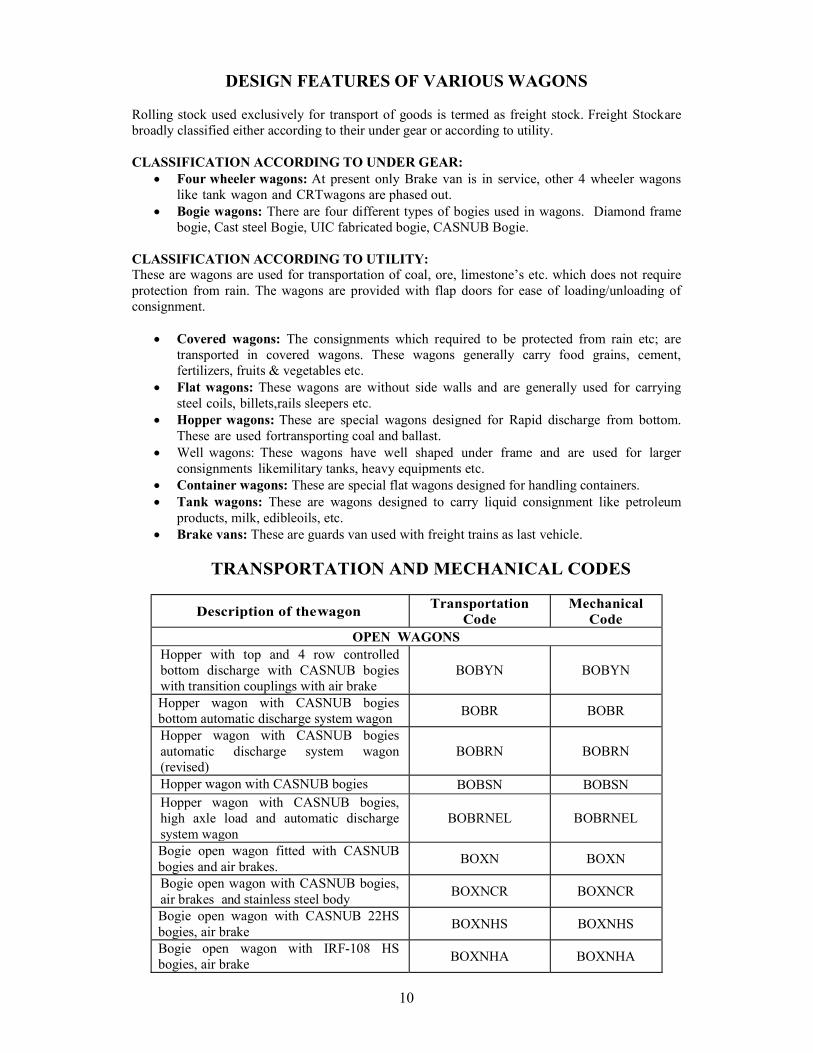
DESIGN FEATURES OF VARIOUS WAGONS Rolling stock used exclusively for transport of goods is termed as freight stock. Freight Stock are broadly classified either according to their under gear or according to utility. CLASSIFICATION ACCORDING TO UNDER GEAR:
Four wheeler wagons: At present only Brake van is in service, other 4 wheeler wagons like tank wagon and CRT wagons are phased out.
Bogie wagons: There are four different types of bogies used in wagons. Diamond frame bogie, Cast steel Bogie, UIC fabricated bogie, CASNUB Bogie.
CLASSIFICATION ACCORDING TO UTILITY: These are wagons are used for transportation of coal, ore, limestone’s etc. which does not require protection from rain. The wagons are provided with flap doors for ease of loading/unloading of consignment.
Covered wagons: The consignments which required to be protected from rain etc; are transported in covered wagons. These wagons generally carry food grains, cement, fertilizers, fruits & vegetables etc.
Flat wagons: These wagons are without side walls and are generally used for carrying steel coils, billets, rails sleepers etc.
Hopper wagons: These are special wagons designed for Rapid discharge from bottom. These are used for transporting coal and ballast.
Well wagons: These wagons have well shaped under frame and are used for larger consignments like military tanks, heavy equipments etc.
Container wagons: These are special flat wagons designed for handling containers. Tank wagons: These are wagons designed to carry liquid consignment like petroleum
products, milk, edible oils, etc. Brake vans: These are guards van used with freight trains as last vehicle.
TRANSPORTATION AND MECHANICAL CODES
Description of the wagon Transportation
Code Mechanical
Code OPEN WAGONS
Hopper with top and 4 row controlled bottom discharge with CASNUB bogies with transition couplings with air brake
BOBYN BOBYN
Hopper wagon with CASNUB bogies bottom automatic discharge system wagon
BOBR BOBR
Hopper wagon with CASNUB bogies automatic discharge system wagon (revised)
BOBRN BOBRN
Hopper wagon with CASNUB bogies BOBSN BOBSN Hopper wagon with CASNUB bogies, high axle load and automatic discharge system wagon
BOBRNEL BOBRNEL
Bogie open wagon fitted with CASNUB bogies and air brakes.
BOXN BOXN
Bogie open wagon with CASNUB bogies, air brakes and stainless steel body
BOXNCR BOXNCR
Bogie open wagon with CASNUB 22HS bogies, air brake
BOXNHS BOXNHS
Bogie open wagon with IRF-108 HS bogies, air brake
BOXNHA BOXNHA
11
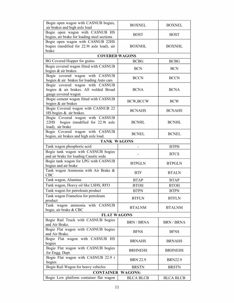
Bogie open wagon with CASNUB bogies, air brakes and high axle load
BOXNEL BOXNEL
Bogie open wagon with CASNUB HS bogies, air brake for loading steel sections
BOST BOST
Bogie open wagon with CASNUB 22HS bogies (modified for 22.9t axle load), air brake
BOXNHL BOXNHL
COVERED WAGONS BG Covered Hopper for grains BCBG BCBG Bogie covered wagon fitted with CASNUB bogies & air brakes
BCN BCN
Bogie covered wagon with CASNUB bogies & air brakes for loading Auto cars
BCCN BCCN
Bogie covered wagon with CASNUB bogies & air brakes. All welded Broad gauge covered wagon
BCNA BCNA
Bogie cement wagon fitted with CASNUB bogies & air brakes
BCW,BCCW BCW
Bogie Covered wagon with CASNUB 22 HS bogies & air brakes.
BCNAHS BCNAHS
Bogie Covered wagon with CASNUB 22HS bogies (modified for 22.9t axle load), air brake
BCNHL BCNHL
Bogie Covered wagon with CASNUB bogies, air brakes and high axle load.
BCNEL BCNEL
TANK WAGONS Tank wagon phosphoric acid - BTPH Bogie tank wagon with CASNUB bogies and air brake for loading Caustic soda
- BTCS
Bogie tank wagon for LPG with CASNUB bogies and air brake
BTPGLN BTPGLN
Tank wagon Ammonia with Air Brake & CBC
BTF BTALN
Tank wagon, Alumina. BTAP BTAP Tank wagon, Heavy oil like LSHS, RFO BTOH BTOH Tank wagon for petroleum product BTPN BTPN Tank wagon Frameless for petroleum product
BTFLN BTFLN
Tank wagon ammonia with CASNUB bogie, air brake & CBC
BTALNM BTALNM
FLAT WAGONS Bogie Rail Truck with CASNUB bogies and Air Brake.
BRN / BRNA BRN / BRNA
Bogie Flat wagon with CASNUB bogies and Air Brake.
BFNS BFNS
Bogie Flat wagon with CASNUB HS bogies
BRNAHS BRNAHS
Bogie Flat wagon with CASNUB bogies for Engg. Dept.
BRHNEHS BRHNEHS
Bogie Flat wagon with CASNUB 22.9 t bogies
BRN 22.9 BRN22.9
Bogie Rail Wagon for heavy vehicles BRSTN BRSTN CONTAINER WAGONS:
Bogie Low platform container flat wagon BLCA BLCB BLCA BLCB
12
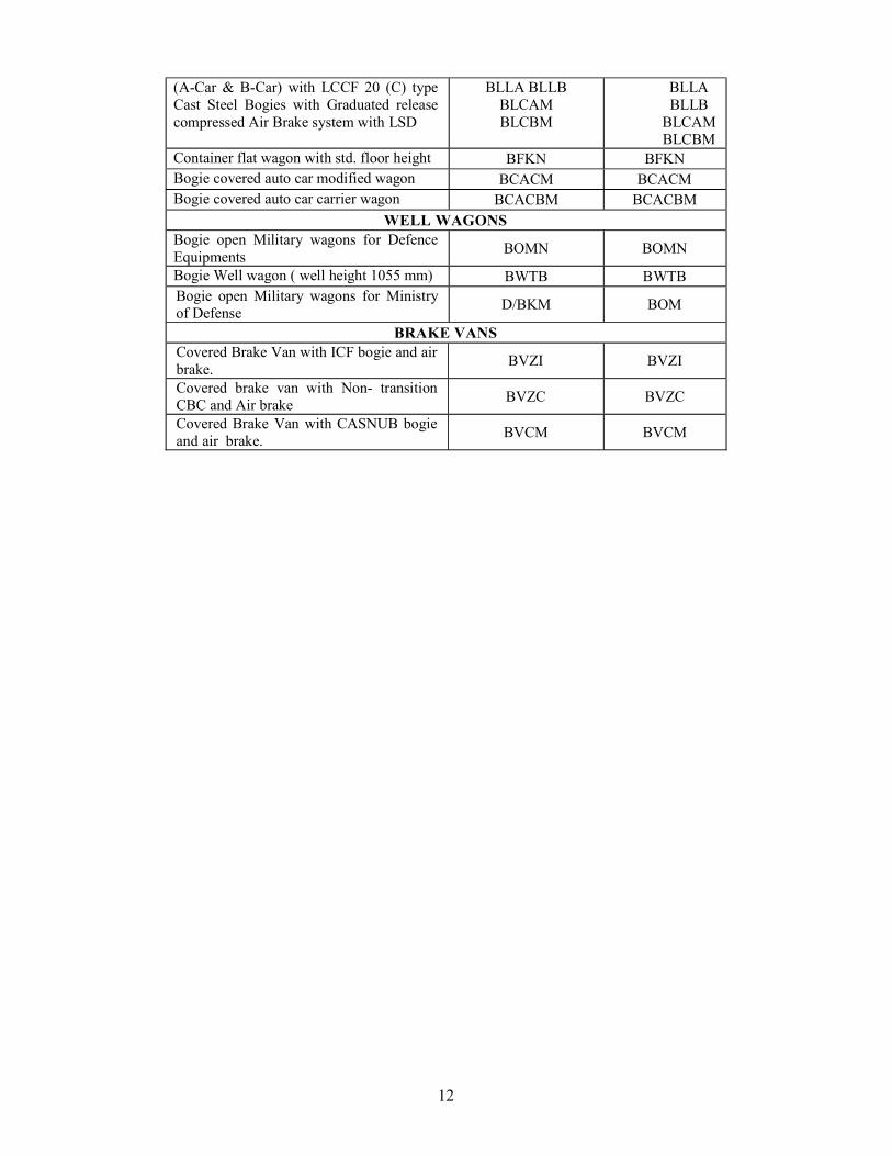
(A-Car & B-Car) with LCCF 20 (C) type Cast Steel Bogies with Graduated release compressed Air Brake system with LSD
BLLA BLLB BLCAM BLCBM
BLLA BLLB
BLCAM BLCBM
Container flat wagon with std. floor height BFKN BFKN Bogie covered auto car modified wagon BCACM BCACM Bogie covered auto car carrier wagon BCACBM BCACBM
WELL WAGONS Bogie open Military wagons for Defence Equipments
BOMN BOMN
Bogie Well wagon ( well height 1055 mm) BWTB BWTB Bogie open Military wagons for Ministry of Defense
D/BKM BOM
BRAKE VANS Covered Brake Van with ICF bogie and air brake.
BVZI BVZI
Covered brake van with Non- transition CBC and Air brake
BVZC BVZC
Covered Brake Van with CASNUB bogie and air brake.
BVCM BVCM
13
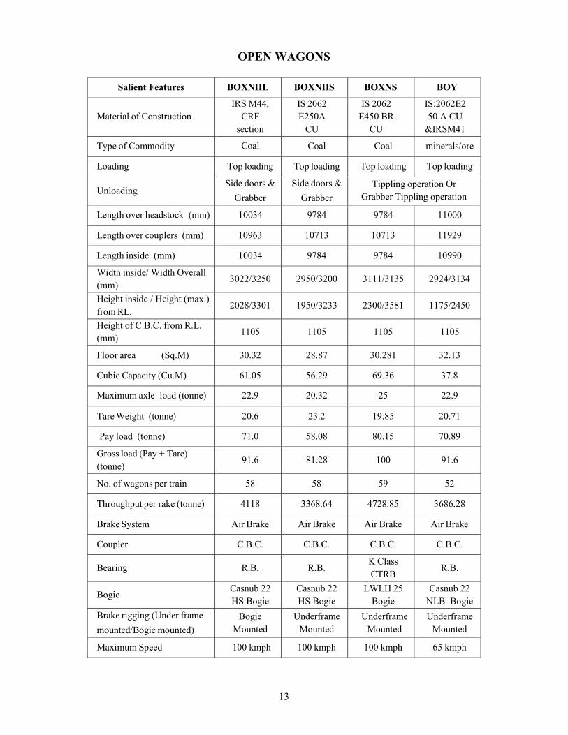
OPEN WAGONS
Salient Features BOXNHL BOXNHS BOXNS BOY
Material of Construction IRS M44,
CRF section
IS 2062 E250 A
CU
IS 2062 E450 BR
CU
IS:2062E250 A CU
& IRSM41
Type of Commodity Coal Coal Coal minerals/ore
Loading Top loading Top loading Top loading Top loading
Unloading Side doors &
Grabber
Side doors &
Grabber
Tippling operation Or Grabber Tippling operation
Length over headstock (mm) 10034 9784 9784 11000
Length over couplers (mm) 10963 10713 10713 11929
Length inside (mm) 10034 9784 9784 10990
Width inside/ Width Overall (mm)
3022/3250 2950/3200 3111/3135 2924/3134
Height inside / Height (max.) from RL.
2028/3301 1950/3233 2300/3581 1175/2450
Height of C.B.C. from R.L. (mm)
1105 1105 1105 1105
Floor area (Sq.M) 30.32 28.87 30.281 32.13
Cubic Capacity (Cu.M) 61.05 56.29 69.36 37.8
Maximum axle load (tonne) 22.9 20.32 25 22.9
Tare Weight (tonne) 20.6 23.2 19.85 20.71
Pay load (tonne) 71.0 58.08 80.15 70.89
Gross load (Pay + Tare) (tonne)
91.6 81.28 100 91.6
No. of wagons per train 58 58 59 52
Throughput per rake (tonne) 4118 3368.64 4728.85 3686.28
Brake System Air Brake Air Brake Air Brake Air Brake
Coupler C.B.C. C.B.C. C.B.C. C.B.C.
Bearing R.B. R.B. K Class CTRB
R.B.
Bogie Casnub 22 HS Bogie
Casnub 22 HS Bogie
LWLH 25 Bogie
Casnub 22 NLB Bogie
Brake rigging (Under frame
mounted/Bogie mounted)
Bogie Mounted
Underframe Mounted
Underframe Mounted
Underframe Mounted
Maximum Speed 100 kmph 100 kmph 100 kmph 65 kmph
14
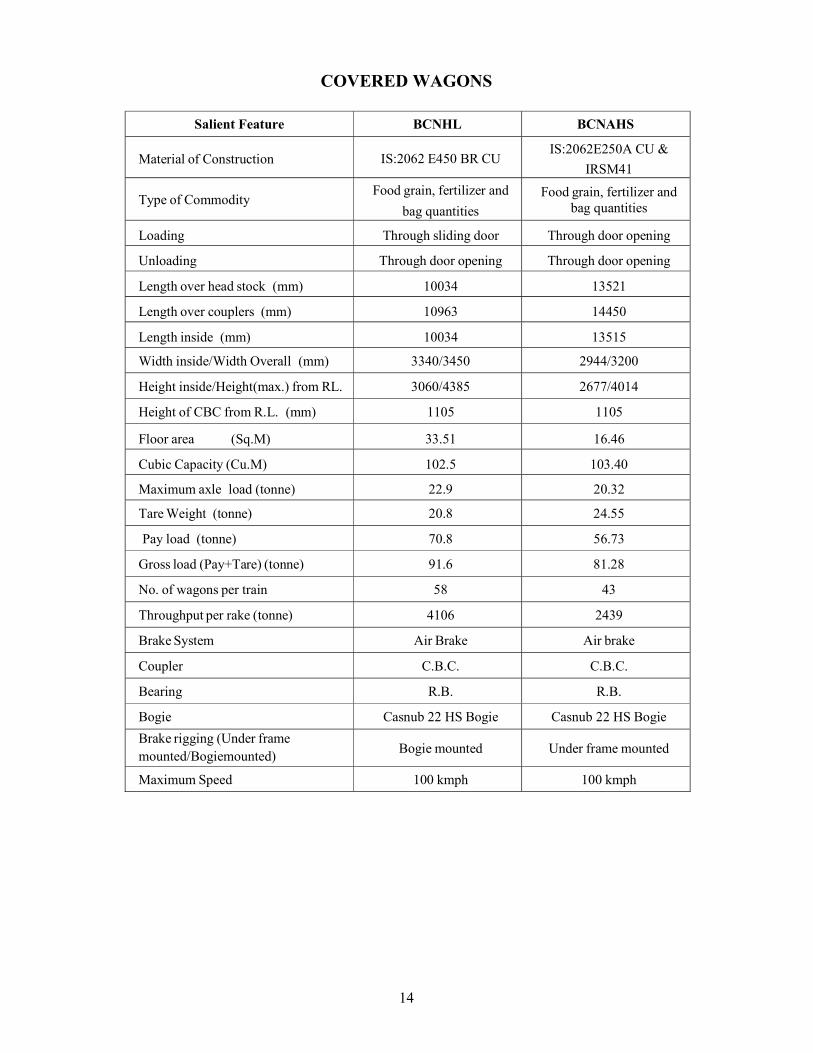
COVERED WAGONS
Salient Feature BCNHL BCNAHS
Material of Construction IS:2062 E450 BR CU IS:2062E250A CU &
IRSM41
Type of Commodity Food grain, fertilizer and
bag quantities
Food grain, fertilizer and bag quantities
Loading Through sliding door Through door opening
Unloading Through door opening Through door opening
Length over head stock (mm) 10034 13521
Length over couplers (mm) 10963 14450
Length inside (mm) 10034 13515
Width inside/Width Overall (mm) 3340/3450 2944/3200
Height inside/Height(max.) from RL. 3060/4385 2677/4014
Height of CBC from R.L. (mm) 1105 1105
Floor area (Sq.M) 33.51 16.46
Cubic Capacity (Cu.M) 102.5 103.40
Maximum axle load (tonne) 22.9 20.32
Tare Weight (tonne) 20.8 24.55
Pay load (tonne) 70.8 56.73
Gross load (Pay+Tare) (tonne) 91.6 81.28
No. of wagons per train 58 43
Throughput per rake (tonne) 4106 2439
Brake System Air Brake Air brake
Coupler C.B.C. C.B.C.
Bearing R.B. R.B.
Bogie Casnub 22 HS Bogie Casnub 22 HS Bogie
Brake rigging (Under frame mounted/Bogie mounted)
Bogie mounted Under frame mounted
Maximum Speed 100 kmph 100 kmph
15
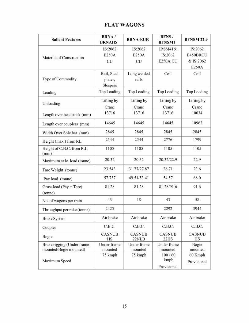
FLAT WAGONS
Salient Features BRNA /
BRNAHS BRNA-EUR
BFNS / BFNSM1
BFNSM 22.9
Material of Construction
IS:2062
E250A
CU
IS:2062
E250A
CU
IRSM41&
IS:2062
E250A CU
IS:2062
E450BRCU
& IS:2062
E250A
Type of Commodity Rail, Steel
plates, Sleepers
Long welded rails
Coil Coil
Loading Top Loading Top Loading Top Loading Top Loading
Unloading Lifting by
Crane
Lifting by
Crane
Lifting by
Crane
Lifting by
Crane
Length over headstock (mm) 13716 13716 13716 10034
Length over couplers (mm) 14645 14645 14645 10963
Width Over Sole bar (mm) 2845 2845 2845 2845
Height (max.) from RL. 2544 2544 2776 1799
Height of C.B.C. from R.L. (mm)
1105 1105 1105 1105
Maximum axle load (tonne) 20.32 20.32 20.32/22.9 22.9
Tare Weight (tonne) 23.543 31.77/27.87 26.71 23.6
Pay load (tonne) 57.737 49.51/53.41 54.57 68.0
Gross load (Pay + Tare)
(tonne)
81.28 81.28 81.28/91.6 91.6
No. of wagons per train 43 18 43 58
Throughput per rake (tonne) 2425 2292 3944
Brake System Air brake Air brake Air brake Air brake
Coupler C.B.C. C.B.C. C.B.C. C.B.C.
Bogie CASNUB
HS CASNUB
22NLB CASNUB
22HS CASNUB
HS Brake rigging (Under frame mounted/Bogie mounted)
Under frame mounted
Under frame mounted
Under frame mounted
Bogie mounted
Maximum Speed
75 kmph 75 kmph 100 / 60 kmph
Provisional
60 Kmph
Provisional
16
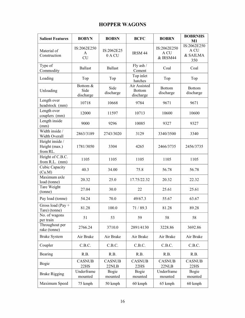
HOPPER WAGONS
Salient Features BOBYN BOBSN BCFC BOBRN BOBRNHS
M1
Material of Construction
IS:2062E250 A
CU
IS:2062E25 0 A CU
IRSM 44 IS:2062E250
A CU & IRSM44
IS:2062E250 A CU
& SAILMA 350
Type of Commodity
Ballast Ballast Fly ash / Cement
Coal Coal
Loading Top Top Top inlet hatches
Top Top
Unloading Bottom &
Side discharge
Side discharge
Air Assisted Bottom
discharge
Bottom discharge
Bottom discharge
Length over headstock (mm)
10718 10668 9784 9671 9671
Length over couplers (mm)
12000 11597 10713 10600 10600
Length inside (mm)
9000 9296 10085 9327 9327
Width inside / Width Overall
2863/3189 2743/3020 3129 3340/3500 3340
Height inside / Height (max.) from RL.
1781/3050 3304 4265 2466/3735 2456/3735
Height of C.B.C. from R.L. (mm)
1105 1105 1105 1105 1105
Cubic Capacity (Cu.M)
40.3 34.00 75.8 56.78 56.78
Maximum axle load (tonne) 20.32 25.0 17.75/22.32 20.32 22.32
Tare Weight (tonne) 27.04 30.0 22 25.61 25.61
Pay load (tonne) 54.24 70.0 49/67.3 55.67 63.67
Gross load (Pay + Tare) (tonne) 81.28 100.0 71 / 89.3 81.28 89.28
No. of wagons per train 51 53 59 58 58
Throughout per rake (tonne) 2766.24 3710.0 2891/4130 3228.86 3692.86
Brake System Air Brake Air Brake Air Brake Air Brake Air Brake
Coupler C.B.C. C.B.C. C.B.C. C.B.C. C.B.C.
Bearing R.B. R.B. R.B. R.B. R.B.
Bogie CASNUB
22HS CASNUB
22NLB CASNUB
22HS CASNUB
22NLB CASNUB
22HS
Brake Rigging Underframe
mounted Bogie
mounted Bogie
mounted Underframe
mounted Bogie
mounted
Maximum Speed 75 kmph 50 kmph 60 kmph 65 kmph 60 kmph
17
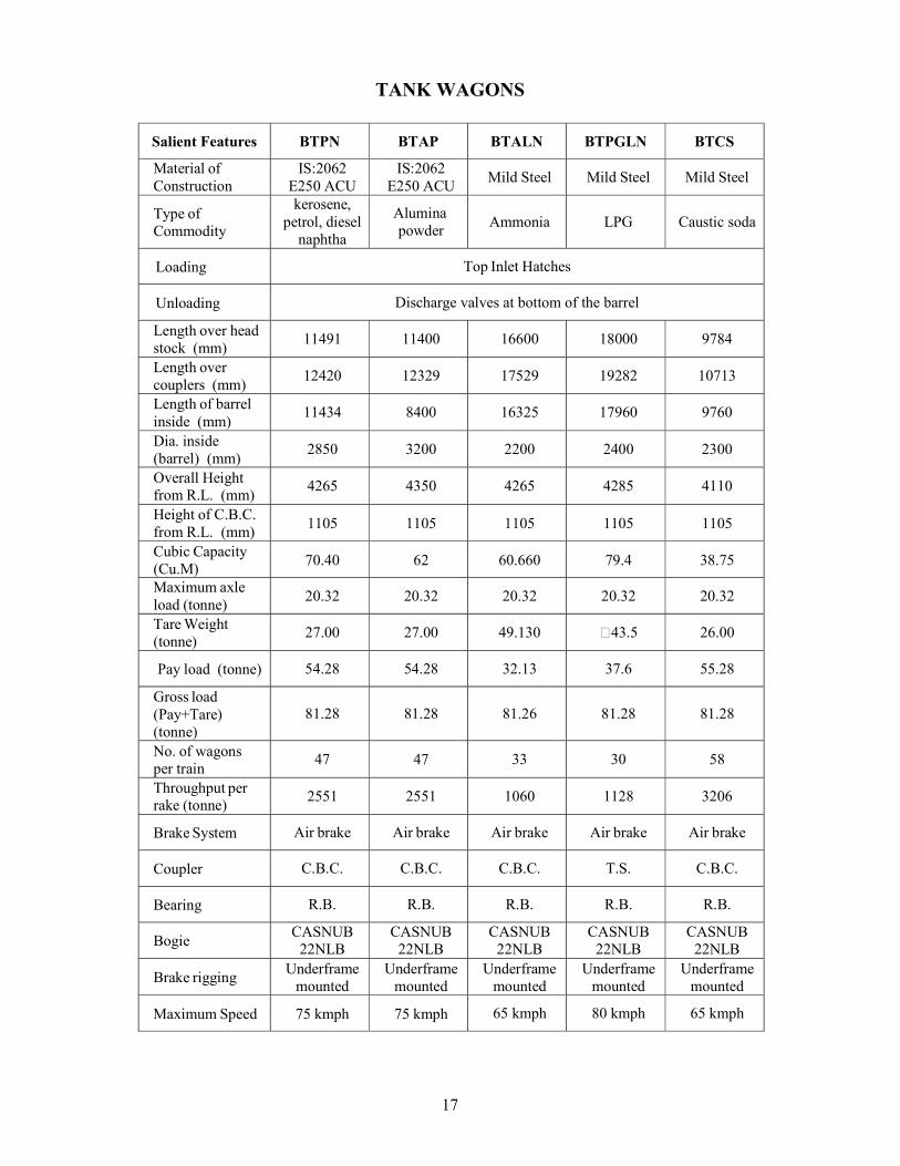
TANK WAGONS
Salient Features BTPN BTAP BTALN BTPGLN BTCS
Material of Construction
IS:2062 E250 ACU
IS:2062 E250 ACU
Mild Steel Mild Steel Mild Steel
Type of Commodity
kerosene, petrol, diesel
naphtha
Alumina powder
Ammonia LPG Caustic soda
Loading Top Inlet Hatches
Unloading Discharge valves at bottom of the barrel
Length over head stock (mm)
11491 11400 16600 18000 9784
Length over couplers (mm)
12420 12329 17529 19282 10713
Length of barrel inside (mm)
11434 8400 16325 17960 9760
Dia. inside (barrel) (mm)
2850 3200 2200 2400 2300
Overall Height from R.L. (mm)
4265 4350 4265 4285 4110
Height of C.B.C. from R.L. (mm)
1105 1105 1105 1105 1105
Cubic Capacity (Cu.M)
70.40 62 60.660 79.4 38.75
Maximum axle load (tonne)
20.32 20.32 20.32 20.32 20.32
Tare Weight (tonne)
27.00 27.00 49.130 43.5 26.00
Pay load (tonne) 54.28 54.28 32.13 37.6 55.28
Gross load (Pay+Tare) (tonne)
81.28 81.28 81.26 81.28 81.28
No. of wagons per train
47 47 33 30 58
Throughput per rake (tonne)
2551 2551 1060 1128 3206
Brake System Air brake Air brake Air brake Air brake Air brake
Coupler C.B.C. C.B.C. C.B.C. T.S. C.B.C.
Bearing R.B. R.B. R.B. R.B. R.B.
Bogie CASNUB
22NLB CASNUB
22NLB CASNUB
22NLB CASNUB
22NLB CASNUB
22NLB
Brake rigging Underframe
mounted Underframe
mounted Underframe
mounted Underframe
mounted Underframe
mounted
Maximum Speed 75 kmph 75 kmph 65 kmph 80 kmph 65 kmph
18
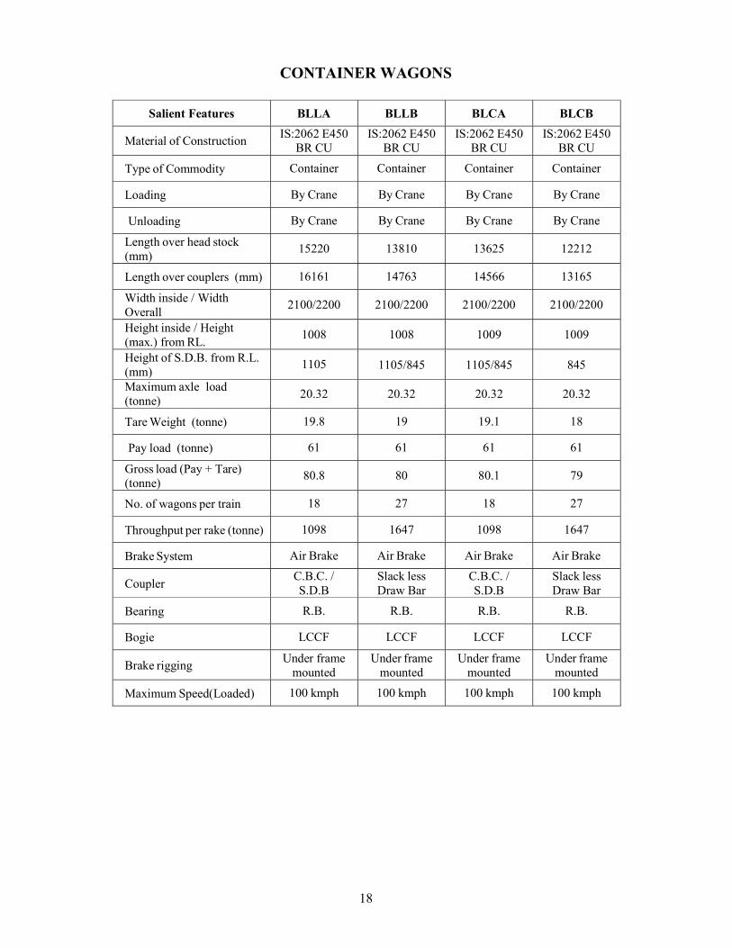
CONTAINER WAGONS
Salient Features BLLA BLLB BLCA BLCB
Material of Construction IS:2062 E450
BR CU IS:2062 E450
BR CU IS:2062 E450
BR CU IS:2062 E450
BR CU
Type of Commodity Container Container Container Container
Loading By Crane By Crane By Crane By Crane
Unloading By Crane By Crane By Crane By Crane
Length over head stock (mm)
15220 13810 13625 12212
Length over couplers (mm) 16161 14763 14566 13165
Width inside / Width Overall
2100/2200 2100/2200 2100/2200 2100/2200
Height inside / Height (max.) from RL.
1008 1008 1009 1009
Height of S.D.B. from R.L. (mm)
1105 1105/845 1105/845 845
Maximum axle load (tonne)
20.32 20.32 20.32 20.32
Tare Weight (tonne) 19.8 19 19.1 18
Pay load (tonne) 61 61 61 61
Gross load (Pay + Tare) (tonne)
80.8 80 80.1 79
No. of wagons per train 18 27 18 27
Throughput per rake (tonne) 1098 1647 1098 1647
Brake System Air Brake Air Brake Air Brake Air Brake
Coupler C.B.C. / S.D.B
Slack less Draw Bar
C.B.C. / S.D.B
Slack less Draw Bar
Bearing R.B. R.B. R.B. R.B.
Bogie LCCF LCCF LCCF LCCF
Brake rigging Under frame
mounted Under frame
mounted Under frame
mounted Under frame
mounted
Maximum Speed(Loaded) 100 kmph 100 kmph 100 kmph 100 kmph
19
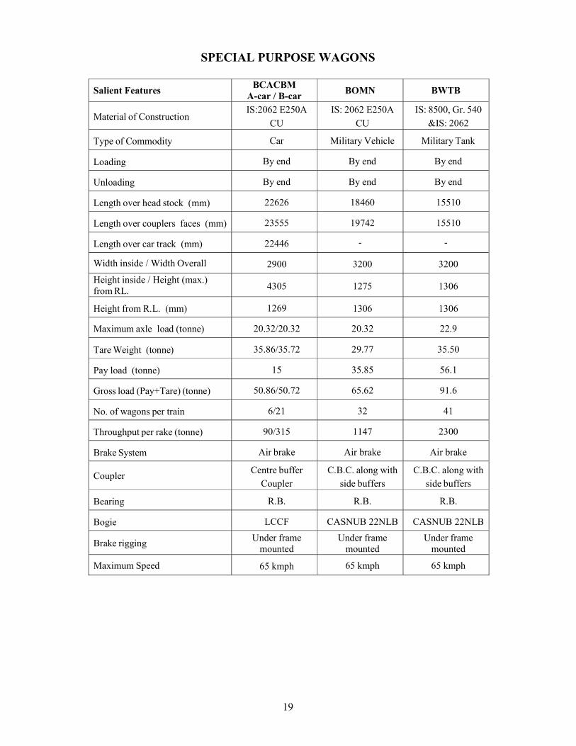
SPECIAL PURPOSE WAGONS
Salient Features BCACBM
A-car / B-car BOMN BWTB
Material of Construction IS:2062 E250A
CU
IS: 2062 E250A
CU
IS: 8500, Gr. 540
&IS: 2062
Type of Commodity Car Military Vehicle Military Tank
Loading By end By end By end
Unloading By end By end By end
Length over head stock (mm) 22626 18460 15510
Length over couplers faces (mm) 23555 19742 15510
Length over car track (mm) 22446 - -
Width inside / Width Overall 2900 3200 3200
Height inside / Height (max.) from RL. 4305 1275 1306
Height from R.L. (mm) 1269 1306 1306
Maximum axle load (tonne) 20.32/20.32 20.32 22.9
Tare Weight (tonne) 35.86/35.72 29.77 35.50
Pay load (tonne) 15 35.85 56.1
Gross load (Pay+Tare) (tonne) 50.86/50.72 65.62 91.6
No. of wagons per train 6/21 32 41
Throughput per rake (tonne) 90/315 1147 2300
Brake System Air brake Air brake Air brake
Coupler Centre buffer
Coupler C.B.C. along with
side buffers C.B.C. along with
side buffers
Bearing R.B. R.B. R.B.
Bogie LCCF CASNUB 22NLB CASNUB 22NLB
Brake rigging Under frame
mounted Under frame
mounted Under frame
mounted
Maximum Speed 65 kmph 65 kmph 65 kmph
20
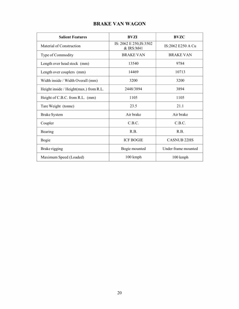
BRAKE VAN WAGON
Salient Features BVZI BVZC
Material of Construction IS: 2062 E 250,IS:3502
& IRS:M41 IS:2062 E250 A Cu
Type of Commodity BRAKE VAN BRAKE VAN
Length over head stock (mm) 13540 9784
Length over couplers (mm) 14469 10713
Width inside / Width Overall (mm) 3200 3200
Height inside / Height(max.) from R.L. 2448/3894 3894
Height of C.B.C. from R.L. (mm) 1105 1105
Tare Weight (tonne) 23.5 21.1
Brake System Air brake Air brake
Coupler C.B.C. C.B.C.
Bearing R.B. R.B.
Bogie ICF BOGIE CASNUB 22HS
Brake rigging Bogie mounted Under frame mounted
Maximum Speed (Loaded) 100 kmph 100 kmph
21
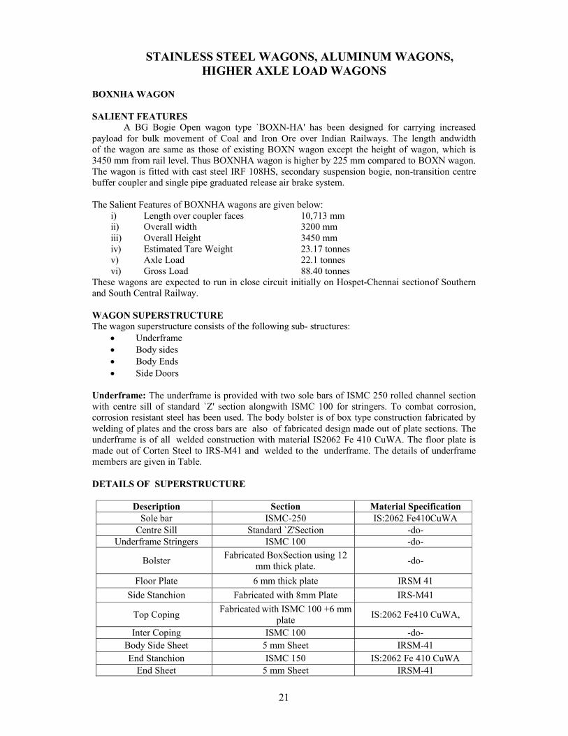
STAINLESS STEEL WAGONS, ALUMINUM WAGONS, HIGHER AXLE LOAD WAGONS
BOXNHA WAGON SALIENT FEATURES
A BG Bogie Open wagon type `BOXN-HA' has been designed for carrying increased payload for bulk movement of Coal and Iron Ore over Indian Railways. The length and width of the wagon are same as those of existing BOXN wagon except the height of wagon, which is 3450 mm from rail level. Thus BOXNHA wagon is higher by 225 mm compared to BOXN wagon. The wagon is fitted with cast steel IRF 108HS, secondary suspension bogie, non-transition centre buffer coupler and single pipe graduated release air brake system.
The Salient Features of BOXNHA wagons are given below:
i) Length over coupler faces 10,713 mm ii) Overall width 3200 mm iii) Overall Height 3450 mm iv) Estimated Tare Weight 23.17 tonnes v) Axle Load 22.1 tonnes vi) Gross Load 88.40 tonnes
These wagons are expected to run in close circuit initially on Hospet-Chennai section of Southern and South Central Railway.
WAGON SUPERSTRUCTURE The wagon superstructure consists of the following sub- structures:
Underframe Body sides Body Ends Side Doors
Underframe: The underframe is provided with two sole bars of ISMC 250 rolled channel section with centre sill of standard `Z' section alongwith ISMC 100 for stringers. To combat corrosion, corrosion resistant steel has been used. The body bolster is of box type construction fabricated by welding of plates and the cross bars are also of fabricated design made out of plate sections. The underframe is of all welded construction with material IS2062 Fe 410 CuWA. The floor plate is made out of Corten Steel to IRS-M41 and welded to the underframe. The details of underframe members are given in Table.
DETAILS OF SUPERSTRUCTURE
Description Section Material Specification
Sole bar ISMC-250 IS:2062 Fe410CuWA Centre Sill Standard `Z' Section -do-
Underframe Stringers ISMC 100 -do-
Bolster Fabricated Box Section using 12
mm thick plate. -do-
Floor Plate 6 mm thick plate IRSM 41
Side Stanchion Fabricated with 8 mm Plate IRS-M41
Top Coping Fabricated with ISMC 100 +6 mm
plate IS:2062 Fe410 CuWA,
Inter Coping ISMC 100 -do- Body Side Sheet 5 mm Sheet IRSM-41 End Stanchion ISMC 150 IS:2062 Fe 410 CuWA
End Sheet 5 mm Sheet IRSM-41
22
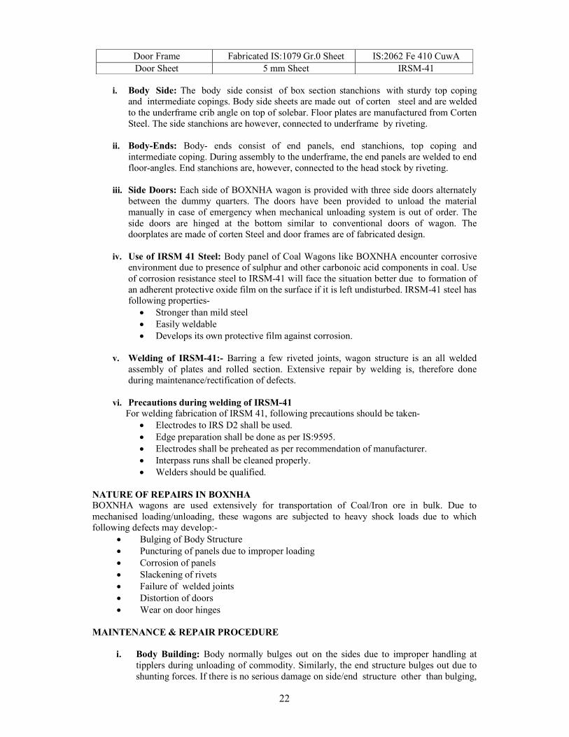
Door Frame Fabricated IS:1079 Gr.0 Sheet IS:2062 Fe 410 CuwA Door Sheet 5 mm Sheet IRSM-41
i. Body Side: The body side consist of box section stanchions with sturdy top coping and intermediate copings. Body side sheets are made out of corten steel and are welded to the underframe crib angle on top of solebar. Floor plates are manufactured from Corten Steel. The side stanchions are however, connected to underframe by riveting.
ii. Body-Ends: Body- ends consist of end panels, end stanchions, top coping and intermediate coping. During assembly to the underframe, the end panels are welded to end floor-angles. End stanchions are, however, connected to the head stock by riveting.
iii. Side Doors: Each side of BOXNHA wagon is provided with three side doors alternately between the dummy quarters. The doors have been provided to unload the material manually in case of emergency when mechanical unloading system is out of order. The side doors are hinged at the bottom similar to conventional doors of wagon. The doorplates are made of corten Steel and door frames are of fabricated design.
iv. Use of IRSM 41 Steel: Body panel of Coal Wagons like BOXNHA encounter corrosive environment due to presence of sulphur and other carbonoic acid components in coal. Use of corrosion resistance steel to IRSM-41 will face the situation better due to formation of an adherent protective oxide film on the surface if it is left undisturbed. IRSM-41 steel has following properties-
Stronger than mild steel Easily weldable Develops its own protective film against corrosion.
v. Welding of IRSM-41:- Barring a few riveted joints, wagon structure is an all welded
assembly of plates and rolled section. Extensive repair by welding is, therefore done during maintenance/rectification of defects.
vi. Precautions during welding of IRSM-41 For welding fabrication of IRSM 41, following precautions should be taken-
Electrodes to IRS D2 shall be used. Edge preparation shall be done as per IS:9595. Electrodes shall be preheated as per recommendation of manufacturer. Interpass runs shall be cleaned properly. Welders should be qualified.
NATURE OF REPAIRS IN BOXNHA BOXNHA wagons are used extensively for transportation of Coal/Iron ore in bulk. Due to mechanised loading/unloading, these wagons are subjected to heavy shock loads due to which following defects may develop:-
Bulging of Body Structure Puncturing of panels due to improper loading Corrosion of panels Slackening of rivets Failure of welded joints Distortion of doors Wear on door hinges
MAINTENANCE & REPAIR PROCEDURE
i. Body Building: Body normally bulges out on the sides due to improper handling at tipplers during unloading of commodity. Similarly, the end structure bulges out due to shunting forces. If there is no serious damage on side/end structure other than bulging,
23
bulges can be effectively removed without dismantling. When bulging of the structure is more than 25 mm, it should be rectified by pulling with the help of chain& screw coupling. Bulging of all welded body sides can be rectified by spot heating and pulling by chain and screw coupling. In case of end bulging, two wagons with bulged end are coupled together and hydraulic jack is applied between them at the bulges. Suitable packing can be interposed between jack and wagon body. For all welded ends spot, heating can be applied for straitening.
ii. Puncturing of Panels: Body side/end panels are punctured due to improper loading and
shunting. Punctured end side panels are repaired by welding of panel patches as per standard practice.
iii. Corrosion of panels : Corrosion of body and floor takes place due to the following:-
Water logging Accumulated dust and refuse which retain moisture for long period Spillage of corrosive fluid due to defective packing Inadequate protection due to poor painting.
The current practice is not to paint the wagon from inside because the painting on inside wall cannot withstand the constant scrubbing action of commodity during mechanized unloading. The following measures should be undertaken-
a) Most important measure to be taken in day to day working is to ensure that the wagon is kept thoroughly cleaned after unloading. It should receive attention in this respect after it has transported a corrosive or hygroscopic commodity.
b) While attending to repairs and panel patching, it is important to ensure that surfaces in contact are well fitted to avoid water pockets. Due care should be taken to clean and paint the affected surface to prevent corrosion.
c) The table below indicates the sizes of panel patches to be used for repairs of corroded panels. If area of the patch extends beyond 260 mm from floor height, either two standard patches of 5 mm thick seat should be used one above another or a single patch of 5 mm thick and 520 mm width should be used. In case two or more adjacent panels require patching at the same time, the complete length of corrosion can be covered by a straight pitch which must extend from stanchion to stanchion.
iv. Slackening of Rivets for BOXNHA wagon: Rivets are provided at the bottom of the
side stanchions to join them with underframe structure. These rivets sometime get loosened due to combined effect of shock, corrosion and wear. Loose rivets can be identified by gentle hammering on rivets which will produce dull sound. The loose rivets shall be cut by chisel and then holes shall be set/repaired by welding. Re-drill to size and put new rivets.
v. Door Defects: The main defect in doors is distortion due to mishandling, wedging or
jammed hinges. The distorted doors shall be taken down and straighten to ensure proper fitment. Worn out /damaged hinges should be replaced by reconditioned/new hinges. After repair, doors must sit flush against striking plates with adequate overlap between levers. Graphite grease should be applied on all the hinges.
vi. Repairs to Door and Fittings: The main defects which arise in side doors of these
wagons are distortion due to mis-handling, jamming of engine and Bulging of door panels due to improper handling during un-loading on tipplers. Distorted or bulged doors must be taken down and straightened to ensure proper fitment. The worn out hinges, which are responsible for sagging/gaping of doors, shall be replaced with new or reconditioned ones. The corroded frame of door must be cut out and replaced by welding after repairs. The doors must sit flush against the wagon structure with proper support.
24
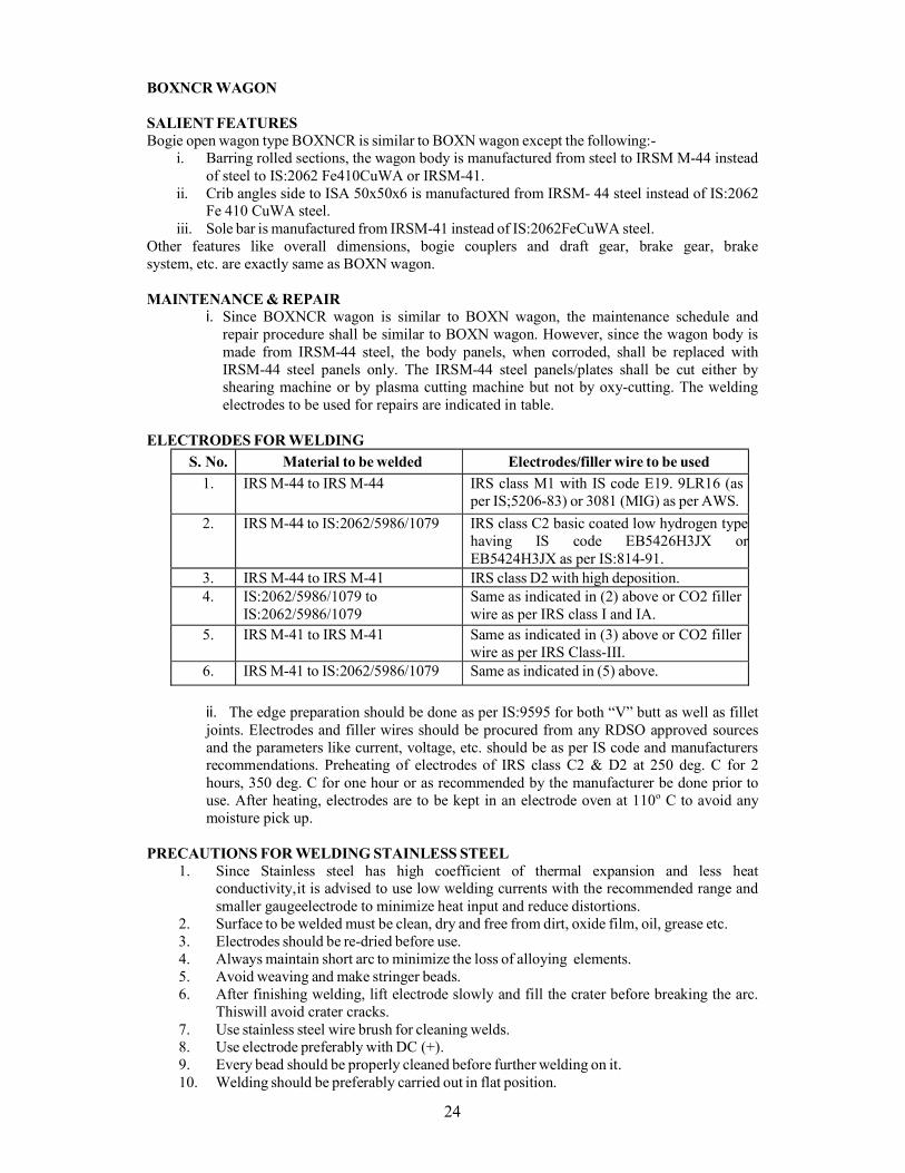
BOXNCR WAGON SALIENT FEATURES Bogie open wagon type BOXNCR is similar to BOXN wagon except the following:-
i. Barring rolled sections, the wagon body is manufactured from steel to IRSM M-44 instead of steel to IS:2062 Fe410CuWA or IRSM-41.
ii. Crib angles side to ISA 50x50x6 is manufactured from IRSM- 44 steel instead of IS:2062 Fe 410 CuWA steel.
iii. Sole bar is manufactured from IRSM-41 instead of IS:2062FeCuWA steel. Other features like overall dimensions, bogie couplers and draft gear, brake gear, brake system, etc. are exactly same as BOXN wagon.
MAINTENANCE & REPAIR
i. Since BOXNCR wagon is similar to BOXN wagon, the maintenance schedule and repair procedure shall be similar to BOXN wagon. However, since the wagon body is made from IRSM-44 steel, the body panels, when corroded, shall be replaced with IRSM-44 steel panels only. The IRSM-44 steel panels/plates shall be cut either by shearing machine or by plasma cutting machine but not by oxy-cutting. The welding electrodes to be used for repairs are indicated in table.
ELECTRODES FOR WELDING
S. No. Material to be welded Electrodes/filler wire to be used
1. IRS M-44 to IRS M-44 IRS class M1 with IS code E19. 9LR16 (as per IS;5206-83) or 3081 (MIG) as per AWS.
2. IRS M-44 to IS:2062/5986/1079 IRS class C2 basic coated low hydrogen typehaving IS code EB5426H3JX orEB5424H3JX as per IS:814-91.
3. IRS M-44 to IRS M-41 IRS class D2 with high deposition. 4. IS:2062/5986/1079 to
IS:2062/5986/1079 Same as indicated in (2) above or CO2 filler wire as per IRS class I and IA.
5. IRS M-41 to IRS M-41 Same as indicated in (3) above or CO2 filler wire as per IRS Class-III.
6. IRS M-41 to IS:2062/5986/1079 Same as indicated in (5) above.
ii. The edge preparation should be done as per IS:9595 for both “V” butt as well as fillet joints. Electrodes and filler wires should be procured from any RDSO approved sources and the parameters like current, voltage, etc. should be as per IS code and manufacturers recommendations. Preheating of electrodes of IRS class C2 & D2 at 250 deg. C for 2 hours, 350 deg. C for one hour or as recommended by the manufacturer be done prior to use. After heating, electrodes are to be kept in an electrode oven at 110o C to avoid any moisture pick up.
PRECAUTIONS FOR WELDING STAINLESS STEEL
1. Since Stainless steel has high coefficient of thermal expansion and less heat conductivity, it is advised to use low welding currents with the recommended range and smaller gauge electrode to minimize heat input and reduce distortions.
2. Surface to be welded must be clean, dry and free from dirt, oxide film, oil, grease etc. 3. Electrodes should be re-dried before use. 4. Always maintain short arc to minimize the loss of alloying elements. 5. Avoid weaving and make stringer beads. 6. After finishing welding, lift electrode slowly and fill the crater before breaking the arc.
This will avoid crater cracks. 7. Use stainless steel wire brush for cleaning welds. 8. Use electrode preferably with DC (+). 9. Every bead should be properly cleaned before further welding on it. 10. Welding should be preferably carried out in flat position.
25
11. Correct electrode size, recommended current, arc length, travel speed and electrode angle must be followed.
12. Any defect like crack, blowhole etc. must be properly gouged out and re-welded. 13. Do not strike arc adjacent to the weld. 14. Tack the welded area correctly to ensure proper gap. 15. Proper welding sequence must be followed to reduce internal stresses and hence reduce
warpage of structure. 16. Always weld towards the free ends.
SURFACE PREPARATION & PAINTING i. The surface preparation and painting schedule for underframe of the wagon shall be as per
standard specification No.G-72 (Rev.1) read with latest amendments. ii. Surface preparation of the wagon body. Degreasing with petroleum hydrocarbon solvent to
IS:1745-1978 (low armatic grade 145/205) or any other degreaser (applicable for both SS,MS and corten steel).
iii. PAINTING OF WAGON BODY For stainless steel
Apply thin coat of etch primer to IS:5666-1970. Two coats of IS:2074-1992, ready mixed paint, air drying, red oxide zinc chrome
priming to minimum DFT of 50 microns. Two coats of IS:123-1962, ready mixed paint, red oxide, brushing, finishing,
semigloss to ISC:446 to IS:5-1994 to a DFT of 80 microns.
For mild steel and corten steel Remove dust, loose rust and mill scale etc. manually by scrapping, chipping and
wire brushing to at least St.2 of IS:9954. Two coats of IS:102-1962, ready mixed paint, brushing, red lead, priming to minimum
DFT of 80 microns. Two coats of IS:123-1962, ready mixed paint, red oxide, brushing, finishing, semi-
gloss to ISC:446 to IS:5-1994 to a DFT of 80 microns. iv. The painting of bogies, couplers and air brake equipment shall be done as given in para
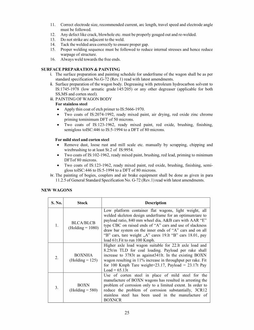
11.2.5 of General Standard Specification No. G-72 (Rev.1) read with latest amendments. NEW WAGONS
S. No. Stock Description
1. BLCA/BLCB
(Holding = 1080)
Low platform container flat wagons, light weight, all welded skeleton design underframe for an optimum tare to payload ratio, 840 mm wheel dia, A&B cars with AAR “E” type CBC on raised ends of “A” cars and use of slackness draw bar system on the inner ends of “A” cars and on all “B” cars, tare weight „A‟ cares 19.lt “B” cars 18.01, pay load 61t.Fit to run 100 Kmph.
2. BOXNHA
(Holding = 125)
Higher axle load wagon suitable for 22.lt axle load and 8.25t/m TLD for coal loading. Payload per rake shall increase to 3783t as against341lt. In the existing BOXN wagon resulting in 11% increase in throughput per rake. Fit for 100 Kmph Tare weight=23.17, Payload = 23.17t Pay Load = 65.13t
3. BOXN
(Holding = 580)
Use of corten steel in place of mild steel for the manufacture of BOXN wagons has resulted in arresting the problem of corrosion only to a limited extent. In order to reduce the problem of corrosion substantially, 3CR12 stainless steel has been used in the manufacture of BOXNCR
26
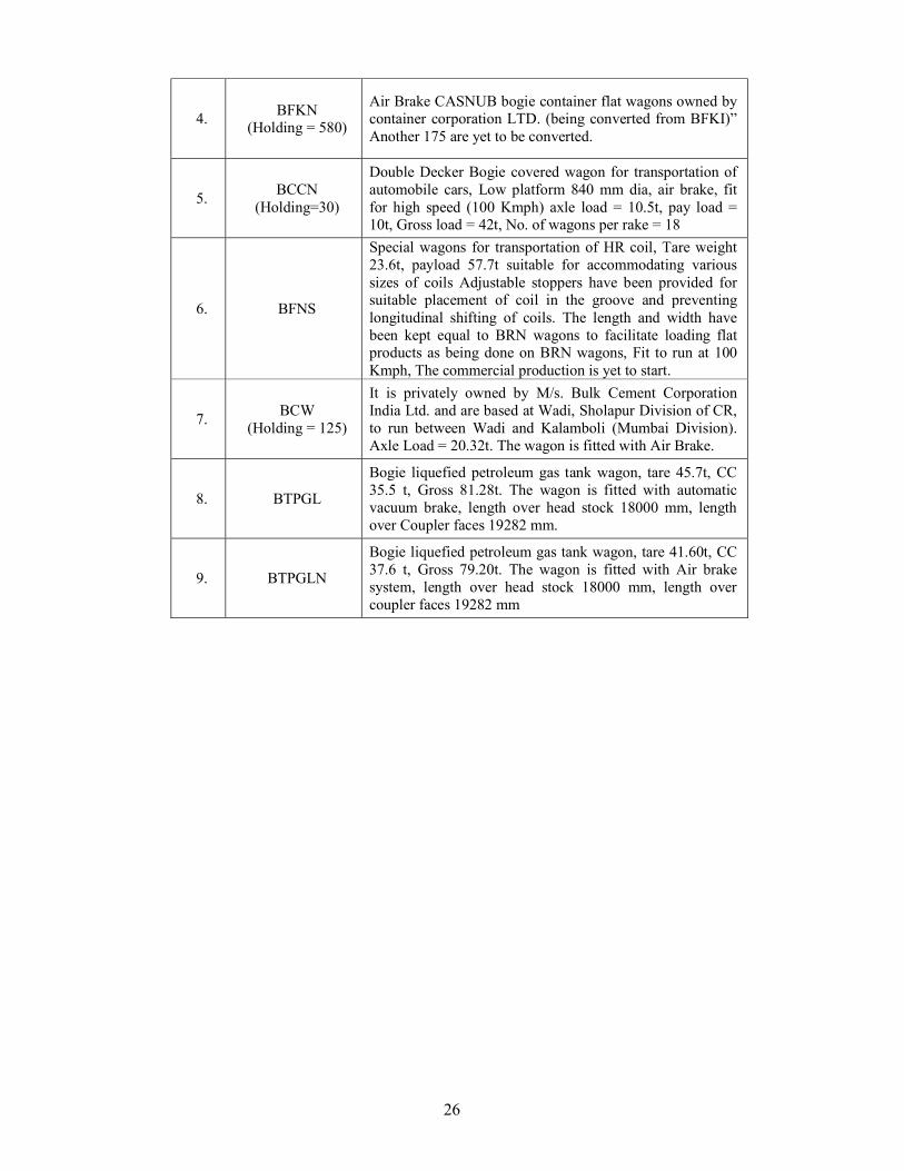
4. BFKN
(Holding = 580)
Air Brake CASNUB bogie container flat wagons owned by container corporation LTD. (being converted from BFKI)” Another 175 are yet to be converted.
5. BCCN
(Holding=30)
Double Decker Bogie covered wagon for transportation of automobile cars, Low platform 840 mm dia, air brake, fit for high speed (100 Kmph) axle load = 10.5t, pay load = 10t, Gross load = 42t, No. of wagons per rake = 18
6. BFNS
Special wagons for transportation of HR coil, Tare weight 23.6t, payload 57.7t suitable for accommodating various sizes of coils Adjustable stoppers have been provided for suitable placement of coil in the groove and preventing longitudinal shifting of coils. The length and width have been kept equal to BRN wagons to facilitate loading flat products as being done on BRN wagons, Fit to run at 100 Kmph, The commercial production is yet to start.
7. BCW
(Holding = 125)
It is privately owned by M/s. Bulk Cement Corporation India Ltd. and are based at Wadi, Sholapur Division of CR, to run between Wadi and Kalamboli (Mumbai Division). Axle Load = 20.32t. The wagon is fitted with Air Brake.
8. BTPGL
Bogie liquefied petroleum gas tank wagon, tare 45.7t, CC 35.5 t, Gross 81.28t. The wagon is fitted with automatic vacuum brake, length over head stock 18000 mm, length over Coupler faces 19282 mm.
9. BTPGLN
Bogie liquefied petroleum gas tank wagon, tare 41.60t, CC 37.6 t, Gross 79.20t. The wagon is fitted with Air brake system, length over head stock 18000 mm, length over coupler faces 19282 mm
27
NEW PATTERN OF TRAIN EXAMINATION OF GOODS STOCK
INTRODUCTION: The efficient working of freight stock is closely linked to the standard of yard maintenance. Several factors are responsible for good and quality examination/repairs in the yard. The method of examination is described as under.
Following are the main feature of new pattern examination of freights trains: 1. The freight train can only be subjected to examine for intensive End to End, Premium End to
End and Close Circuit Rakes. 2. The practice of safe to run examination of freight trains per se may be discontinued. 3. En route Rolling-in-Examination of freight trains may be discontinued. However rolling in
examination as part of intensive examination will continue. 4. Post loading examination by C&W Staff may be discontinued for all type of stock (except
loading of steel consignment). This check is to be carried out by Guard and Driver as per standard proforma issued by Railway Board. The post loading check must be carried out by C&W Staff and securing of steel bundles with lashing chains may be ensured.
5. After Tippling the rake will be offered for post tippling examination, in case of less than three rakes per day, the check may be carried out by guard and driver as per standard proforma issued by railway board. In cases 3 or more rakes are being tippling, post tippling check will be done by Skelton C&W staff. After tippling the rakes should be subjected to post tippling check either by C&W Staff or by GUARD & Driver in case of non provision of C&W Staff in siding.
6. It should be ensured that unexamined lead (after unloading before next C&W Point) of freight trains running end to end pattern or invalid BPC in case of premier & cc rakes does not exceed 400 kilometer.
7. Since multiple loading and unloading are permitted in CC & Premium Rakes, its movement will be monitored through FOIS by Traffic Department with C & W control.
8. In case of mechanized loading and unloading (i.e. in BOXN wagon), examination by C&W will be desirable.
9. The CC rakes shall be offered for PME in empty condition at the CC base depot where the CC Rake was originally formed.
10. ROH and POH wagons from CC rake will be marked and detach at base Depot. 11. The rake integrity of CC rake as listed in the BPC should be maintained. However up to 4
wagons may be replaced by good examined wagons in the entire run between the two PME (05 BLC or one unit in case of BLC rakes allowed for attended or replaced).
END TO END EXAMINATION:
In End to end pattern examination, the train will be examined in empty condition in nominated intensive yard and BPC will remain valid up to unloading point after loading under following conditions. i) The integrity of examined rake should not be disturbed by more than 4 wagons. ii) The examined rake should not be stabled by 24 hours and above at any examination yard. iii) Man-hours are decided as 56 for End to End pattern examination. iv) The destination must be endorsed on the BPC of loaded rake.
PREMIUM RAKES:
The BPC of premium rakes shall have a validity of 12 days with 3 days additional grace period to facilitate examination in unloaded condition. The following stamp shall be provided on the BPC of Premium rakes:
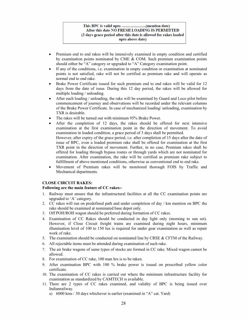
28
Premium end to end rakes will be intensively examined in empty condition and certified
by examination points nominated by CME & COM. Such premium examination points should either be “A” category or upgraded to “A” Category examination point.
If any of the conditions, i.e. examination in empty condition or examination at nominated points is not satisfied, rake will not be certified as premium rake and will operate as normal end to end rake.
Brake Power Certificate issued for such premium end to end rakes will be valid for 12 days from the date of issue. During this 12 day period, the rakes will be allowed for multiple loading / unloading.
After each loading / unloading, the rake will be examined by Guard and Loco pilot before commencement of journey and observations will be recorded under the relevant columns of the Brake Power Certificate. In case of mechanized loading/ unloading, examination by TXR is desirable.
The rakes will be turned out with minimum 95% Brake Power. After the completion of 12 days, the rakes should be offered for next intensive
examination at the first examination point in the direction of movement. To avoid examination in loaded condition, a grace period of 3 days shall be permitted. However, after expiry of the grace period, i.e. after completion of 15 days after the date of issue of BPC, even a loaded premium rake shall be offered for examination at the first TXR point in the direction of movement. Further, in no case, Premium rakes shall be offered for loading through bypass routes or through yards which are not nominated for examination. After examination, the rake will be certified as premium rake subject to fulfillment of above mentioned conditions, otherwise as conventional end to end rake.
Movement of Premium rakes will be monitored thorough FOIS by Traffic and Mechanical departments.
CLOSE CIRCUIT RAKES: Following are the main feature of CC rakes:-
1. Railway must ensure that the infrastructural facilities at all the CC examination points are upgraded to ‘A’ category.
2. CC rakes will run on predefined path and under completion of day / km mention on BPC the rake should be examined at nominated base depot only.
3. Off POH/ROH wagon should be preferred during formation of CC rakes. 4. Examination of CC Rakes should be conducted in day light only (morning to sun set).
However, if Close Circuit freight trains are examined during night hours, minimum illumination level of 100 to 150 lux is required for under gear examination as well as repair work of rake.
5. The examination should be conducted on nominated line by CRSE & CFTM of the Railway. 6. All rejectable items must be attended during examination of such rake. 7. The air brake wagons of same types of stocks are formed in CC rake. Mixed wagon cannot be
allowed. 8. For examination of CC rake, 100 man hrs is to be taken. 9. After examination BPC with 100 % brake power is issued on prescribed yellow color
certificate. 10. The examination of CC rakes is carried out where the minimum infrastructure facility for
examination as standardized by CAMTECH is available. 11. There are 2 types of CC rakes examined, and validity of BPC is being issued over
Indian railway. a) 6000 kms / 30 days whichever is earlier (examined in “A” cat. Yard)
29
b) 7500 kms / 35 days whichever is the earliest (examined at Special “A” cat. Yard) 12. Grace period of 5 days is allowed if the rake is moving towards the base depot.
13. The rakes are handed over to Traffic Department for multiple loading/unloading within the validity of BPC and GDR check.
14. Listed wagons on BPC are allowed to run. En route if detachment or attachment of more than 4 wagons is done without examination by SSE/JE (C&W), BPC should be treated as invalid (In case of BLC 5 wagons/one unit)
15. Movement of CC rakes will be monitored through FOIS by Traffic Department with Mechanical Department.
16. If the rakes stabled in yard more than 24 hours, the rakes must be offered for C&W examination otherwise BPC will be treated as invalid.
17. The km runs must be endorsed by Driver and Guard on BPC in relevant column. 18. If the kilometrage have not been logged correctly and continuously the BPC will be deemed
to be valid for 20 days only from the date of issue. Further, zonal Railways shall maintain detailed record w.r.t. en route detachments. Brake power and detachment during examination of these rakes and give monthly feedback to board on their performance. Railway must ensure that infrastructural facilities at all the above points are upgraded to ‘A’ category. GDR CHECK
1. GDR check should be done for post loading/back loading of a rake. 2. After tippling, the rake will be subjected to post-tippling examination and the check may
be carried out by Guard & Loco pilot. 3. If BPC has become invalid then GDR Check should be done before taking the rake to the
nearest train examination point in the direction of movement. 4. In case of the Attachment/detachment of the wagon, or reversal of power at Non-TXR
point, continuity of the Brake pipe pressure must be ensured by Loco pilot & Guard. Guidelines for GDR Check All CBCs couplings are coupled and it should also be ensured that CBCs are locked and the operating handle properly set in the slot.
a. All Air hoses pipes are properly coupled and secured. b. Air hose at the end of train is properly placed on air hose carrier.(stand) c. All the angle cocks are in open condition except for the angle cock at the end of the train
which is in closed condition. d. Empty/Load device handles are kept in the correct position on loaded/empty rakes. e. Numbers of dummy/in-operative cylinders are not exceeding the limits prescribed. f. There are no loose fittings/hanging parts like pull rod, brake beam, safety brackets and
brake blocks, etc. which endanger safe running of the train. g. All hand brake levers/wheels are released. h. It shall be ensured by the Guard that all the doors of the covered & open wagons are
properly closed or secured in open condition in case of perishable/lime stone consignments.
i. Any other abnormalities noticed are to be recorded in the BPC. Guard & Loco pilot shall prepare a memo jointly on a plain sheet in triplicate indicating the brake power and deficiencies, if any, and shall append their signatures and both of them shall retain a copy of the same.
30
j. Guard should obtain SM/YM‟s endorsement on two copies of the joint memo and hand over the third for SM/YM‟s record.
k. SM/YM will inform the section control after making the endorsement on the joint memo and obtain clearance for the train to move.
l. Continuity of the Train pipe is confirmed through VHF/Whistle code before starting the train.
m. Fitment of Air Brake Gauges is mandatory by Guard of the train. n. Ensuring that the rake is cleared with twin pipe brake system if BPC has endorsement as
twin pipe, subject to a compatible loco being attached to the train.
INTENSIVE EXAMINATION OF GOODS TRAINS The intensive examination is a rejection standard examination with intensive repair to rolling stock, the purpose of which being to permit extended runs of through trains while raising the general standard of fitness of rolling stock by giving concentrated attention to the wagon at the time of dispatch from originating yard to destination. During intensive repair all rejectable and desirable items are to be attended. Following steps must be taken to attend in intensive examination: a) Rolling in examination including axle box feeling
Only all terminating trains requiring intensive examination should be given rolling in examination while entering a train examination depot. The following inspection should be carried out during rolling in examination: i) In-motion inspection and observation of under gear of wagons for any loose or dangling
components and flat places on tyres/wheels. ii) Immediately after the train has come to a halt, all axle boxes should be felt/ temperature
measurement taken with contact-less thermometers and those, which are found running at high temperature (more than 900C), should be marked sick.
iii) Examination of any abnormal behavior of any of the vehicles or any other observation which may be related to the safety of the train.
iv) The rolling-in examination must be conducted to detect any skidded wheel. v) Incoming BPC should be collected by the C&W staff.
b) Intensive examination of goods trains including repairs, detachment of sick wagons and brake testing
During intensive examination of goods train, following items must be attended. 1. Inspection and repairs of running gear fittings. 2. Inspection and repairs of brake gear and spring gears. 3. Inspection and repairs of draw and buffing gear. 4. Checking and making good the deficiency of safety fittings, safety brackets, safety loops, etc. 5. Replacement of brake blocks:
a) Brake blocks should be replaced on reaching condemning thickness. b) To ensure correct fitment of brake blocks, only spring steel key as per RDSO Drg.
No. W/BG-6150 should only be used. c) After fitment of brake block and key on brake head fitment of split pin should be ensured.
6. Correct fitment of washers, bulb cotters and all brake gear pins to be ensured. 7. Correct functioning and positioning of empty load device. 8. Checking and proper securing of doors of covered wagons. 9. Look for abnormal and /or unequal CBC height, Wear plate, Knuckle, etc. to the extent
possible by visual examination. In case of doubt, the CBC height should be measured. 10. Meticulous check of brake cylinders, distributor valves, auxiliary reservoirs, control
reservoirs and other pipe joints should be carried out to ensure that these are in proper working order. Isolating cocks and angle cocks to be checked for proper position. Brake cylinder should be released and checked for piston stroke for empty and loaded position.
31
11. After brakes are released, the wheel profile should be examined visually. If any defect is noticed, it should be checked with tyre defect gauge and wagon to be marked sick for wheel changing, if required. If bent axle is suspected wheel gauging must be done.
12. The bogies, complete side frames and bolsters are to be visually examined for cracks and missing parts. Bolster springs, Snubber, spigots, centre pivots fastening, side bearer and elastomeric pads should be checked for defects, if any.
13. Examine brake rigging components with special attention to brake beam deformation and wear on integral brake shoe bracket. Check intactness of the pull and push rods with pins, washers, split pins and cotters, etc. Hand brakes must be checked for smooth and effective operation.
14. Visual examination of under frame members, body, door mechanism, CBC wear or deficiency of parts to be marked and their operation to be checked.
15. Brake power should be tested. 16. Where a rejectable defect cannot be attended to on the train in the yard, the wagon shall be
damaged labelled for attention in the sick line. 17. Brake adjustment shall be done as per wheel diameter by adjusting End Pull Rod hole
position. 18. Visual examination of under frame members, body, door mechanism for any defects/
damages. Attend, if necessary.
c) Issue of Intensive Brake Power Certificate after ensuring brake continuity of formed load
After ensuring brake continuity of intensive examined rake, necessary BPC to be issued to the guard & driver as per type of examination for further movement of the rake. BRAKE POWER CERTIFICATE (BPC):
This is a certificate jointly signed by guard, driver and C&W supervisor prepared in triplicate by SSE/JE (C&W) after ensuring vehicle attached in train is fit to run and required amount of air pressure is maintain in engine and brake van / last vehicle. BPC CONTAINS:
It contains BPC number with date, issued by yard/division/Railway, train number, loco number, loads and stock, break up of load, total no. of brake cylinders, brake power % age of the train, amount of air pressure in engine and brake van and first and last two vehicles number respectively.
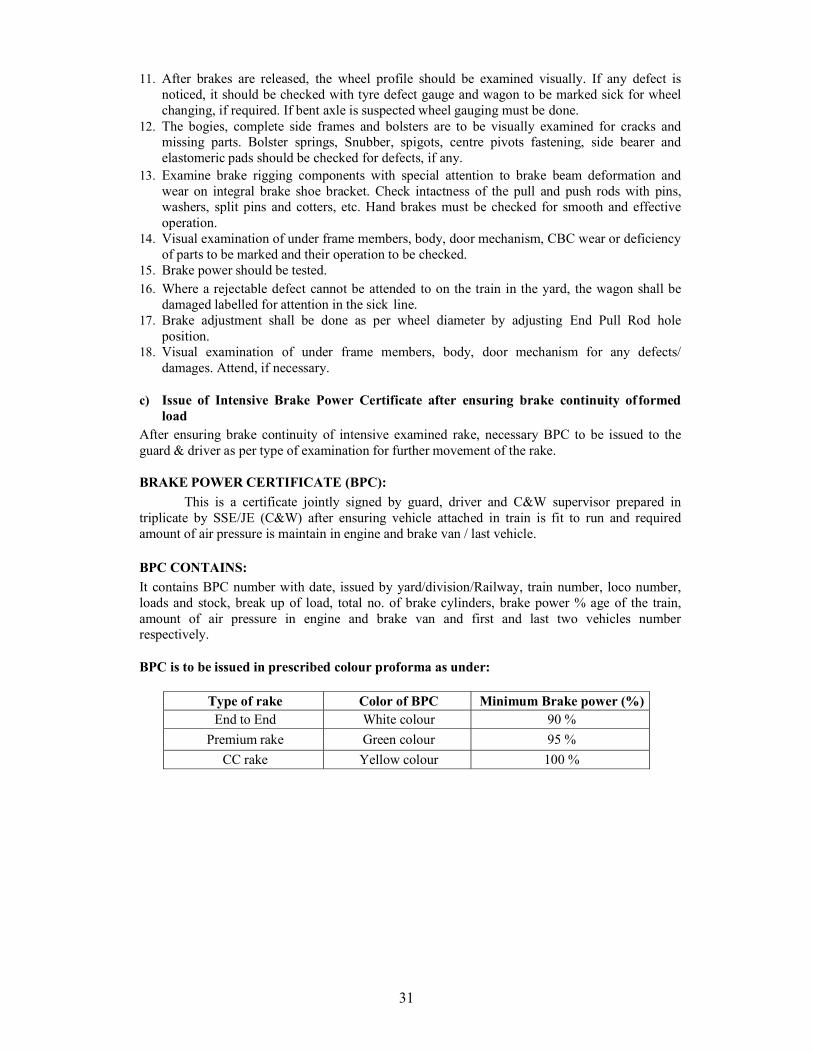
BPC is to be issued in prescribed colour proforma as under:
Type of rake Color of BPC Minimum Brake power (%) End to End White colour 90 %
Premium rake Green colour 95 %
CC rake Yellow colour 100 %
32
HUCK/LOCK BOLTS
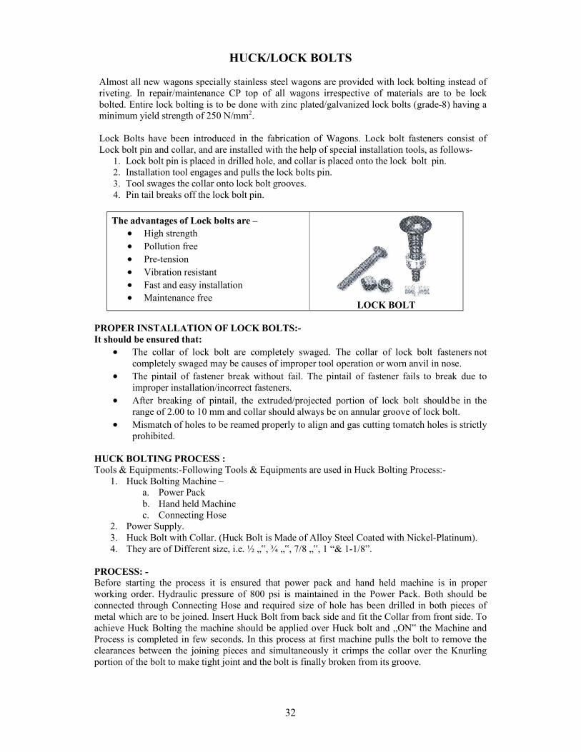
Almost all new wagons specially stainless steel wagons are provided with lock bolting instead of riveting. In repair/maintenance CP top of all wagons irrespective of materials are to be lock bolted. Entire lock bolting is to be done with zinc plated/galvanized lock bolts (grade-8) having a minimum yield strength of 250 N/mm2. Lock Bolts have been introduced in the fabrication of Wagons. Lock bolt fasteners consist of Lock bolt pin and collar, and are installed with the help of special installation tools, as follows-
1. Lock bolt pin is placed in drilled hole, and collar is placed onto the lock bolt pin. 2. Installation tool engages and pulls the lock bolts pin. 3. Tool swages the collar onto lock bolt grooves. 4. Pin tail breaks off the lock bolt pin.
The advantages of Lock bolts are – High strength Pollution free Pre-tension Vibration resistant Fast and easy installation Maintenance free
LOCK BOLT PROPER INSTALLATION OF LOCK BOLTS:- It should be ensured that:
The collar of lock bolt are completely swaged. The collar of lock bolt fasteners not completely swaged may be causes of improper tool operation or worn anvil in nose.
The pintail of fastener break without fail. The pintail of fastener fails to break due to improper installation/incorrect fasteners.
After breaking of pintail, the extruded/projected portion of lock bolt should be in the range of 2.00 to 10 mm and collar should always be on annular groove of lock bolt.
Mismatch of holes to be reamed properly to align and gas cutting to match holes is strictly prohibited.
HUCK BOLTING PROCESS : Tools & Equipments:-Following Tools & Equipments are used in Huck Bolting Process:-
1. Huck Bolting Machine – a. Power Pack b. Hand held Machine c. Connecting Hose
2. Power Supply. 3. Huck Bolt with Collar. (Huck Bolt is Made of Alloy Steel Coated with Nickel-Platinum). 4. They are of Different size, i.e. ½ „‟, ¾ „‟, 7/8 „‟, 1 “& 1-1/8”.
PROCESS: - Before starting the process it is ensured that power pack and hand held machine is in proper working order. Hydraulic pressure of 800 psi is maintained in the Power Pack. Both should be connected through Connecting Hose and required size of hole has been drilled in both pieces of metal which are to be joined. Insert Huck Bolt from back side and fit the Collar from front side. To achieve Huck Bolting the machine should be applied over Huck bolt and „ON‟ the Machine and Process is completed in few seconds. In this process at first machine pulls the bolt to remove the clearances between the joining pieces and simultaneously it crimps the collar over the Knurling portion of the bolt to make tight joint and the bolt is finally broken from its groove.
33
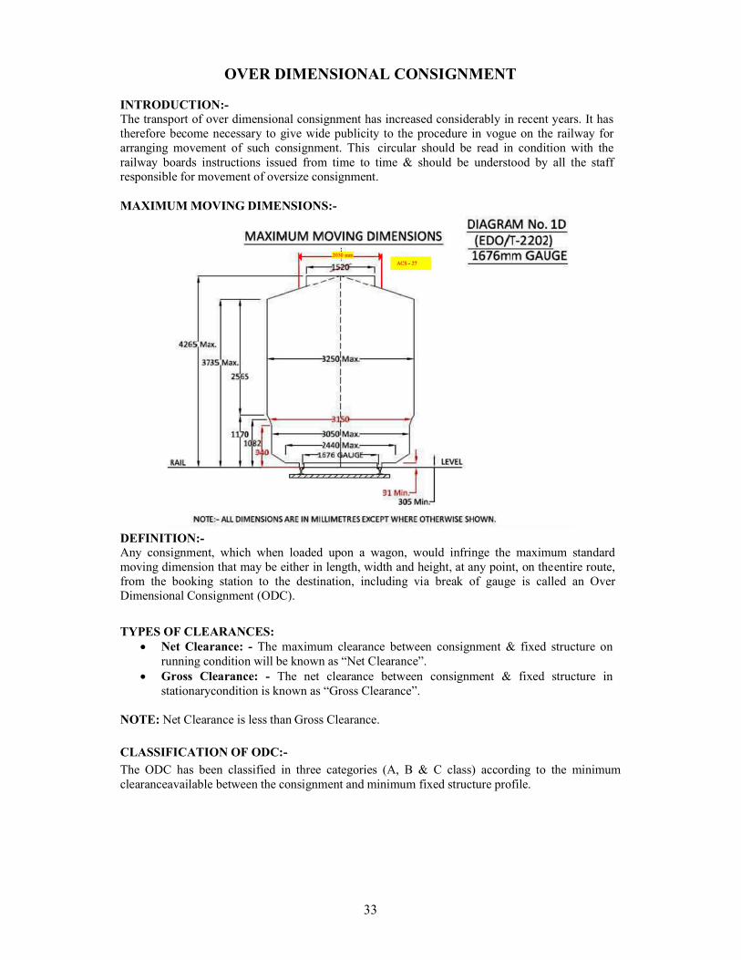
OVER DIMENSIONAL CONSIGNMENT
INTRODUCTION:- The transport of over dimensional consignment has increased considerably in recent years. It has therefore become necessary to give wide publicity to the procedure in vogue on the railway for arranging movement of such consignment. This circular should be read in condition with the railway boards instructions issued from time to time & should be understood by all the staff responsible for movement of oversize consignment.
MAXIMUM MOVING DIMENSIONS:-
DEFINITION:- Any consignment, which when loaded upon a wagon, would infringe the maximum standard moving dimension that may be either in length, width and height, at any point, on the entire route, from the booking station to the destination, including via break of gauge is called an Over Dimensional Consignment (ODC).
TYPES OF CLEARANCES: Net Clearance: - The maximum clearance between consignment & fixed structure on
running condition will be known as “Net Clearance”. Gross Clearance: - The net clearance between consignment & fixed structure in
stationary condition is known as “Gross Clearance”.
NOTE: Net Clearance is less than Gross Clearance.
CLASSIFICATION OF ODC:-
The ODC has been classified in three categories (A, B & C class) according to the minimum clearance available between the consignment and minimum fixed structure profile.
34
GENERAL INSTRUCTION: If any package before loading exceeds the following dimensions, the party concern should be advised to apply the COM of the zonal railway for sanction for the movement of the consignment. a) Length : 13716 mm b) Height : 2745 mm at centre c) Width : 2997 mm d) Top width : 610 mm
On receipt of the loading instructions from the COM, the consignment should be loaded on a suitable truck should be lashed and packed properly to avoid shifting of the consignment enroute during transportation. The greatest weight on any pair of wheel shall not exceed for which the wheel is designed and the weight should be eventually distributed as far as possible on two rails. After loading, the consignment should be measured in the following manners:
a) Maximum height of the consignment from the rail level. b) Overall width: Overall width means, after loading of the consignment, both sides to be
measured from the center of the truck. The overall width is the double the amount of greater side measurement.
c) Overall width where height is maximum. d) Height where width is maximum.
The measurement should be taken by a competent C&W supervisor and should be sent to COM for getting sanction for classification of load, and route through which it will pass. Before dispatch of the load, fit certificate must be obtained from C&W supervisor. All ODCs must follow the routes selected by the COM.
Loco yard, Goods shed and transshipment shed must be avoided for transportation of ODC. Shunting must also be avoided. If any shifting take place, the consignment should be brought to proper place and again it will be properly lashed and packed for its safe running.
PROCEDURE FOR VERIFICATION IN CE’s OFFICE:- The following particulars shall be furnished in duplicate by the COM’s office to the Chief Engineer’s office in respect of any oversized consignment.
Length of consignment
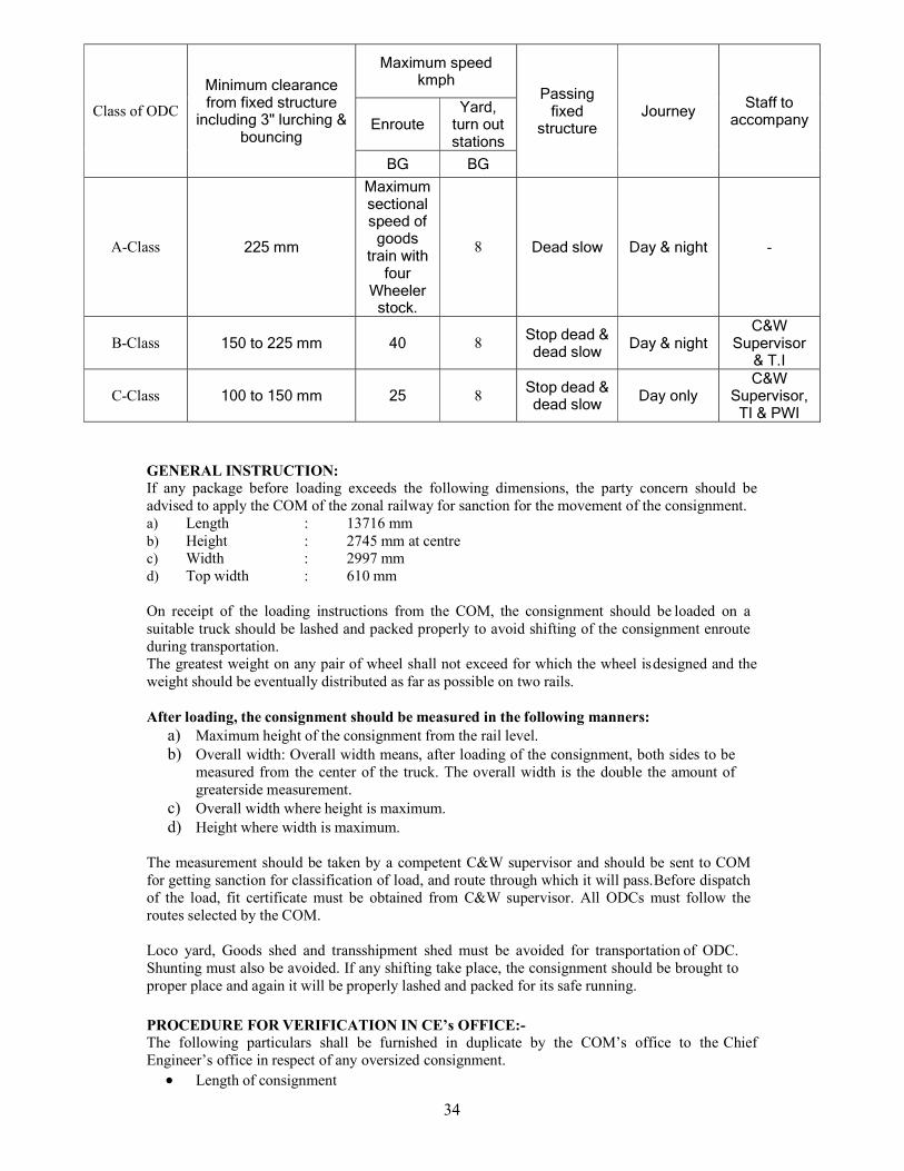
Class of ODC
Minimum clearance from fixed structure
including 3" lurching & bouncing
Maximum speed kmph
Passing fixed
structure Journey
Staff to accompany Enroute
Yard, turn out stations
BG BG
A-Class 225 mm
Maximum sectional speed of
goods train with
four Wheeler
stock.
8 Dead slow Day & night -
B-Class 150 to 225 mm 40 8 Stop dead & dead slow
Day & night C&W
Supervisor & T.I
C-Class 100 to 150 mm 25 8 Stop dead & dead slow
Day only C&W
Supervisor, TI & PWI
35
Height of consignment at top center & side Width of the consignment at top & bottom Weight of consignment Booking station Destination station The route by which the consignment is to be booked
In case of old consignment a sketch showing end & front elevation with the complete dimension Length, width, Height & Weight shall be sent along with the application in duplicate.
Each division will send up to date rolling diagrams showing the moving dimension on the division by 30th September of every year to the Chief Engineer’s Office. Clearance of OHE structure (height of contact wire, horizontal distance of OHE, columns etc.) shall be submitted by the traction branch of the division to the chief engineer’s office. Thereafter CE’s office must be advised to receive the diagram whenever the clearances etc. are affected to rising of track, construction of new structure & alternation of existing structure etc.
Construction organization shall submit to CE’s office roll diagram showing supposed clearance before taking any work likely to affect the moving dimension. While under taking any construction work, such as extension of existing platform, construction of new platform, shelters, road over bridge etc. Whether by open line or construction branch, it must be ensured that the clearance as shown in the Chief Bridge Engineer.
SANCTIONING BY CHIEF ENGINEER’s OFFICE:- After verifying the particulars of the consignment vis-à-vis the moving dimension, sectional movement of the consignment will be communicated by the chief engineer’s office to the COM’s office. Such cases which are not within the powers of the chief engineer’s office shall be submitted to CRS for sanction by the chief bridge engineer & as soon as he sanction for the movement is received from the CRS, the same shall be communicated to the COP by the chief engineer’s office.
In each case section will specify the speed restrictions to be observed, the track & structures to be avoided, lowering of track, lifting of overhead electrical equipment, shutting off of power etc. as necessary. COM’s office will convey the sanction to the divisions & the division concerned shall be issue massage to all concerned official by wire & in case the movement over a particular division is through locations where restrictive unavoidable structures or overhead equipment are located, in addition will send conformation copies & obtain acknowledgment. If acknowledgement is not received in time from any of the concerned officials it shall be the duty of the divisional control office to obtain in on telephone & recode it in the control diary to ensure that the concerned staffs are aware of the condition of movement & their respective duties.
36
IRCA- INDIAN RAILWAY CONFRENCE ASSOCIATION
GENERAL INFORMATION HEAD QUARTER- DRM Building New Delhi WORKING: Under Rly Board(Member Traffic) ADMINISTRATIVE CONTROL-GM/Northern Rly HEAD: General Secretary (Traffic /Commercial Deptt.).
AIM: To upgrade the maintenance quality of rolling stock (carriage & wagon). Rate fixing and preparation of passenger ticket and goods charges. To dissolve the operational dispute between two interchanging point. Pre & final examination during POH &ROH to be carried out by neutral TXR (IRCA) and
final fit memo to be issued to the concerning officer of the w/shop or sick line. Repair cost during POH & ROH & Other repair of carriage & wagon to be assess & repair cost
sent to railway board. Suggestion and rake assessment of amount paid by commercial department. On account of
railway claim to be service time to time and proposal sent to railway.
WORK: Mechanical deptt.: Final fitness of off POH / NPOH, off ROH & other wagon lying in sick
line for miscellaneous defects to be issued by IRCA men i.e. NTXR. Operating deptt.: To dissolve the operational dispute between two railways, preparation of
time table etc. Commercial deptt: Rate fixing & preparation of passenger ticket & goods stock. Accounts: Accountant assessment of the expenditure to be checked by IRCA.
MECHANICAL DEPTT. CONCERN: IRCA gives out the rules for the standards condemning sizes of various components used on rolling stock. They also give the guidelines for the maintenance of rolling stock in workshop and in open line. The rule books used for the carriage & wagon issued for the carriage & wagon branch of mechanical deptt. are: part III for wagon stock & part IV for coaching stock. IRCA part III & part IV contain 4 chapters
Chapter Details Chapter I Definitions Chapter II Workshop repair practice Chapter III Maintenance practice in open line Chapter IV Rejection rules
REJECTION RULES FOR BROAD GAUGE GOODS STOCK 4.1 From Workshops, stock must not be allowed with any rejectable or other defects. The stock must be turned out after complete repairs, in accordance with the rules laid down in Chapter–II and Chapter-III. The permissible wear and clearances on different components shall conform to limits and tolerances specified for workshops. 4.2 From sick lines, stock must not be allowed with rejectable defects. Rules laid down in Chapter II and III shall be followed. 4.3 Notwithstanding any provision in the Rules, rolling stock must not be allowed to run, if in the opinion of C&W Supervisor, it is in such a condition as to cause an accident. 4.4 Broad Gauge goods stock with any of the defects listed below shall not be allowed in service. Such of the clauses which have direct bearing on safe running of trains have been prefixed with the letter ‘S’ for the guidance of the staff concerned.
37
UNDER-FRAME DEFECTS ‘S’ A crack extending into the web and visible on both sides of an under frame member. A loose patch on an under frame member, or a patched member showing signs of crippling. ‘S’ Head-stock of Broad Gauge wagon bent so that the centre of CBC face is displaced in any direction more than 35 mm from its normal position. NOTE: No packing is permissible except on wagons booked for repairs. ‘S’ Truss rod brackets deficient or fractured. Three or more adjacent body brackets broken or deficient. Floor boards of an empty wagon deficient or defective. Centre sill worn out, broken/crack, gusset plate broken/crack. BOGIE DEFECTS BOGIE FRAME DEFECTS ‘S’ Side frame cracked/broken. ‘S’ Trolley frame out of square or damaged ‘S’ Any member of trolley frame cracked or welding failed. This shall include knee plates, gusset plates and diagonal bars with their rivets broken or deficient. BOLSTER DEFECTS ‘S’ Bolster cracked / broken Bolster liner deficient/weld given up. ‘S’ Bolster safety brackets broken or improperly secured. CENTRE PIVOT DEFECTS ‘S’ Top/bottom centre pivot cracked/broken. Top/Bottom centre pivot huck bolts/rivets loose/deficient Pivot pin, shackle lock/lock pin deficient. Pivot plate casting or pin broken cotter and/or rivet deficient. BOGIE SUSPENSION DEFECTS ‘S’ Any coiled bearing spring cracked or broken/shifted. ‘S’ Wedge cracked/broken. Any plate of a laminated bearing spring or any coiled bearing spring cracked or broken Bearing spring buckle loose, broken, cracked and/or packing plate loose or deficient. Any plate or buckle displaced from its central position by 13 mm or more. Bearing spring buckle not sitting square in the axle box housing or crown packing where fitted. BRAKE RIGGING DEFECTS ‘S’ Brake block deficient, broken at the eye, not secured properly with the fastening of nut or cotter or worn so thin so that the flange of the wheel is 6 mm or less from the brake beam collar on brake application. The shoe type renewable brake block when the thickness is reduced to 10 mm. ‘S’ Any defect in brake rigging preventing application or release of brakes. ‘S’ Any safety strap/bracket/hanger pull rod or brake beam not in accordance with rule 2.12.1.2. ‘S’ Any pin deficient or broken or any split pin or cotter deficient or free to work out in the brake gear. ‘S’ Brake blocks key missing or improper fitment. Brake not applying on dropping the hand brake lever by its own weight, or brake screw or nut inoperative. Hand brake wheel/assembly deficient/defective, Hand brake lever collar not secured by rivet to the brake shaft. Brake gear slack adjuster or any part of assembly deficient. AIR BRAKE SYSTEM DEFECTS ‘S’ Stock without air brake connection from coupling to coupling. ‘S’ Stock with deficient/damaged or inoperative distributor valve or its parts, common pipe bracket with control reservoir, cut off angle cocks, dirt collector, brake cylinder, auxiliary reservoir check valve and hose coupling assembly for BP and FP.
38
‘S’ Stock having excessive leakage from the system. ‘S’ Stock with damaged pipes and pipe fittings. 'S' Brake van quick coupling deficient/defective. CENTRE BUFFER COUPLER (CBC) DEFECTS ‘S’ Centre Buffer Coupler knuckle pin broken, bent or incorrect size and its improper fastening arrangement. ‘S’ Centre Buffer Coupler body visibly cracked or with any part broken off and/ or missing. Coupler body shank or housing worn by 10 mm. Coupler body with cracked/bent guard arm. Striker casting cracked more than 25 mm at any location. Striker casting wear plate deficient, cracked or worn out up to 5 mm. Striker casting stud deficient. ‘S’ Centre Buffer Coupler yoke pin support plate missing, broken or its wear plate worn out. ‘S’ Centre Buffer Coupler shank cracked or bent or out of alignment. CBC shank wear plate missing where originally fitted. ‘S’ Centre Buffer Coupler lock lift assembly so defective that the CBC cannot be coupled/ uncoupled. 'S' CBC with defective/deficient components. ‘S’ Coupler operating mechanism not functioning properly. Full knuckle throw, locking not obtained due to defective components, anti creep arrangement not functioning. ‘S’ Interference in the normal movement of coupler due to improper clearances. ‘S’ Cracks in the knuckle side wall. Distance between the nose of the knuckle and guard arm exceeds limit due to wear in the components and distorted guard arm. ‘S’ Knuckle thrower and lock lift assembly excessively worn, broken, bent or otherwise distorted so that CBC cannot be uncoupled. ‘S’ Excessive wear on lock. 'S'- Indicates safety item. However, it should be primarily understood that service wear limits mentioned in this book are not safety limits. Service wear limits are far more restrictive when compared with wear limits for safety. Hence, any variation from service wear limits as stipulated should, under no circumstances be considered unsafe for running of wagons on trains.
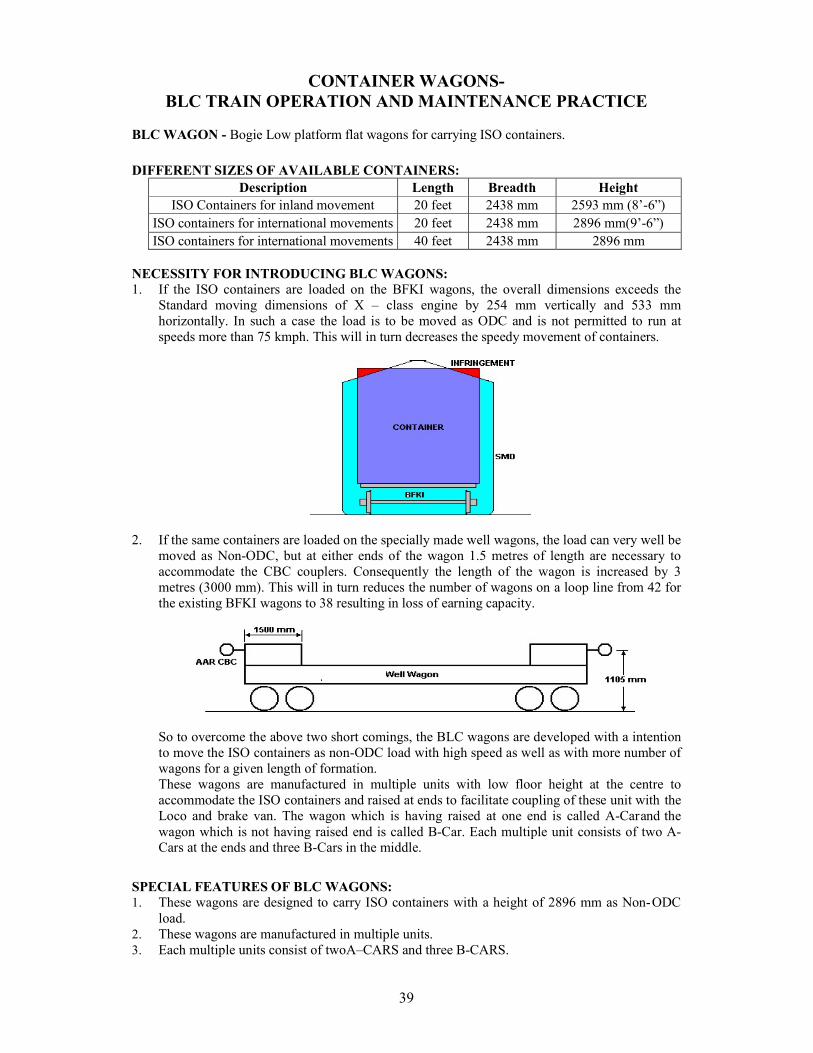
39
CONTAINER WAGONS- BLC TRAIN OPERATION AND MAINTENANCE PRACTICE
BLC WAGON - Bogie Low platform flat wagons for carrying ISO containers.
DIFFERENT SIZES OF AVAILABLE CONTAINERS: Description Length Breadth Height
ISO Containers for inland movement 20 feet 2438 mm 2593 mm (8’-6”) ISO containers for international movements 20 feet 2438 mm 2896 mm(9’-6”) ISO containers for international movements 40 feet 2438 mm 2896 mm
NECESSITY FOR INTRODUCING BLC WAGONS: 1. If the ISO containers are loaded on the BFKI wagons, the overall dimensions exceeds the
Standard moving dimensions of X – class engine by 254 mm vertically and 533 mm horizontally. In such a case the load is to be moved as ODC and is not permitted to run at speeds more than 75 kmph. This will in turn decreases the speedy movement of containers.
2. If the same containers are loaded on the specially made well wagons, the load can very well be moved as Non-ODC, but at either ends of the wagon 1.5 metres of length are necessary to accommodate the CBC couplers. Consequently the length of the wagon is increased by 3 metres (3000 mm). This will in turn reduces the number of wagons on a loop line from 42 for the existing BFKI wagons to 38 resulting in loss of earning capacity.
So to overcome the above two short comings, the BLC wagons are developed with a intention to move the ISO containers as non-ODC load with high speed as well as with more number of wagons for a given length of formation. These wagons are manufactured in multiple units with low floor height at the centre to accommodate the ISO containers and raised at ends to facilitate coupling of these unit with the Loco and brake van. The wagon which is having raised at one end is called A-Car and the wagon which is not having raised end is called B-Car. Each multiple unit consists of two A-Cars at the ends and three B-Cars in the middle.
SPECIAL FEATURES OF BLC WAGONS: 1. These wagons are designed to carry ISO containers with a height of 2896 mm as Non- ODC
load. 2. These wagons are manufactured in multiple units. 3. Each multiple units consist of two A–CARS and three B-CARS.
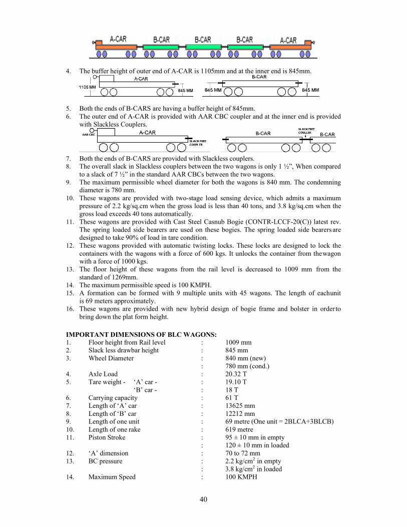
40
4. The buffer height of outer end of A-CAR is 1105mm and at the inner end is 845mm.
5. Both the ends of B-CARS are having a buffer height of 845mm. 6. The outer end of A-CAR is provided with AAR CBC coupler and at the inner end is provided
with Slackless Couplers.
7. Both the ends of B-CARS are provided with Slackless couplers. 8. The overall slack in Slackless couplers between the two wagons is only 1 ½”, When compared
to a slack of 7 ½” in the standard AAR CBCs between the two wagons. 9. The maximum permissible wheel diameter for both the wagons is 840 mm. The condemning
diameter is 780 mm. 10. These wagons are provided with two-stage load sensing device, which admits a maximum
pressure of 2.2 kg/sq.cm when the gross load is less than 40 tons, and 3.8 kg/sq.cm when the gross load exceeds 40 tons automatically.
11. These wagons are provided with Cast Steel Casnub Bogie (CONTR-LCCF-20(C)) latest rev. The spring loaded side bearers are used on these bogies. The spring loaded side bearers are designed to take 90% of load in tare condition.
12. These wagons provided with automatic twisting locks. These locks are designed to lock the containers with the wagons with a force of 600 kgs. It unlocks the container from the wagon with a force of 1000 kgs.
13. The floor height of these wagons from the rail level is decreased to 1009 mm from the standard of 1269mm.
14. The maximum permissible speed is 100 KMPH. 15. A formation can be formed with 9 multiple units with 45 wagons. The length of each unit
is 69 meters approximately. 16. These wagons are provided with new hybrid design of bogie frame and bolster in order to
bring down the plat form height.
IMPORTANT DIMENSIONS OF BLC WAGONS: 1. Floor height from Rail level : 1009 mm 2. Slack less drawbar height : 845 mm 3. Wheel Diameter : 840 mm (new)
: 780 mm (cond.) 4. Axle Load : 20.32 T 5. Tare weight - ‘A’ car - : 19.10 T
‘B’ car - : 18 T 6. Carrying capacity : 61 T 7. Length of ‘A’ car : 13625 mm 8. Length of ‘B’ car : 12212 mm 9. Length of one unit : 69 metre (One unit = 2BLCA+3BLCB) 10. Length of one rake : 619 metre 11. Piston Stroke : 95 ± 10 mm in empty
: 120 ± 10 mm in loaded 12. ‘A’ dimension : 70 to 72 mm 13. BC pressure : 2.2 kg/cm2 in empty
: 3.8 kg/cm2 in loaded 14. Maximum Speed : 100 KMPH
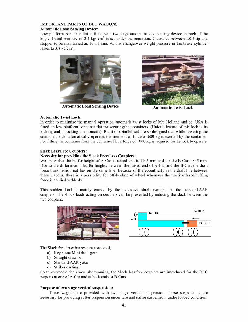
41
IMPORTANT PARTS OF BLC WAGONS: Automatic Load Sensing Device: Low platform container flat is fitted with two stage automatic load sensing device in each of the bogie. Initial pressure of 2.2 kg/ cm2 is set under the condition. Clearance between LSD tip and stopper to be maintained as 16 ±1 mm. At this changeover weight pressure in the brake cylinder raises to 3.8 kg/cm2.
Automatic Load Sensing Device
Automatic Twist Lock
Automatic Twist Lock: In order to minimize the manual operation automatic twist locks of M/s Holland and co. USA is fitted on low platform container flat for securing the containers. (Unique feature of this lock is its locking and unlocking is automatic). Radii of spindle head are so designed that while lowering the container, lock automatically operates the moment of force of 600 kg is exerted by the container. For fitting the container from the container flat a force of 1000 kg is required for the lock to operate.
Slack Less/Free Couplers: Necessity for providing the Slack Free/Less Couplers: We know that the buffer height of A-Car at raised end is 1105 mm and for the B-Car is 845 mm. Due to the difference in buffer heights between the raised end of A-Car and the B-Car, the draft force transmission not lies on the same line. Because of the eccentricity in the draft line between these wagons, there is a possibility for off-loading of wheel whenever the tractive force/buffing force is applied suddenly.
This sudden load is mainly caused by the excessive slack available in the standard AAR couplers. The shock loads acting on couplers can be prevented by reducing the slack between the two couplers.
The Slack free draw bar system consist of,
a) Key stone Mini draft gear b) Straight draw bar c) Standard AAR yoke d) Striker casting.
So to overcome the above shortcoming, the Slack less/free couplers are introduced for the BLC wagons at one of A-Car and at both ends of B-Cars.
Purpose of two stage vertical suspension: These wagons are provided with two stage vertical suspension. These suspensions are
necessary for providing softer suspension under tare and stiffer suspension under loaded condition.
42
The two stage vertical suspension is necessary to provide higher static deflection in empty condition, so that the spring off-loading in the empty condition lies within limits. Vertical suspension in loaded condition is stiffer on account of the constraint in the space between the bolster and the bogie frame.
The softer suspension is provided between the body and bolster and the stiffer suspension is provided between the bolster and bogie frame.
Load Distribution: The weight distribution between centre pivot and side bearers is optimized to avoid
hunting. 90% of the body weight under tare condition is borne by the side bearers which are of spring loaded design to ensure that no hunting takes place. The spring loaded side bearer arrangement has the distinct advantage of retaining the load distribution between centre pivot and side bearers irrespective of any manufacturing inaccuracies in the body and bogie bolster as well as the condition of the wheel (New or Worn). 10% of body weight under tare condition & full pay load will be borne by Centre Pivot.
MAINTENANCE PATTERN OF BLC WAGON:- Special conditions for examination of container trains (Close Circuit) 1. BLC wagon is maintenance free or requires very less maintenance. It is subjected to maintain
for in CLOSED CIRCUIT RAKES. 2. The BLC rakes shall be based for maintenance at the nominated CC base depot. 3. The examinations of BLC rakes shall be done in empty condition, i.e. without containers on
the wagons. 4. The BPC is valid for 6000km OR 30days for ‘A’ Class & 7500km OR 35 days for ‘A’
SPL Class yard whichever is earlier. 5. In case kilometers are not logged on BPC, the validity of BPC shall be for 20 days only from
date of its issue (including the date of issue). The rake shall be returned back to its base depot within validity of the BPC.
6. If the rake stabled in the train examination yard for more than 24 hrs or more the rake is subjected safe to run examination and same BPC is revalidated for remaining period of the BPC.
7. If one unit i.e. five wagons of the CC rake is detached/attached this is not INVALID. 8. Rake with invalid BPC shall normally not be permitted to run in service. Further loading
shall not be permitted in rakes with invalid BPC. 9. If the km /days of the BPC is completed before reaching the base depot, the validity of the
BPC is extended for 7 days for one time unloading only. If it is in loaded condition after unloading the rake is sent in empty condition to base depot.
10. If km of run is not logged on BPC by crew, the BPC valid for 15 days from the date of issue
43
of BPC. 11. All the rakes examined on CC pattern shall be subjected to safe to run examination by TXR
(at TXR point) or by Guard & Loco pilot (at other points after every loading / unloading. PROBLEM FACED DURING MAINTANENCE AND OPERATION OF BLC RAKE:- 1. Due to low platform container, it is trouble to repair and testing of brake power properly and
consuming more time. 2. Provision of LSD, the plunger accumulating dust / cement and due to such problem, it is
necessary to pay more attention for avoiding mall functioning of LSD. 3. Some container depot are not having C&W staff so loading /Unloading .The revalidation is
necessary for locking of container is not done due to this locking of container is not so easy reroute.
4. Due to floating bolster on run while functioning of LSD .The plunger of VTA valve is not inserting directly into its housing and bending effects occurs on plunger, resulting damage to the VTA valve.
Side bearer – BLC unit
Wedge Block Load Sensing Device
44
REPAIR & MAINTENANCE OF GOODS STOCK—ROH PRACTICE
ROH OF CASNUB BOGIE WAGON: ROH of air braked wagons with Casnub bogie are given ROH schedule at the nominated sick line where proper facilities are provided. For undertaking ROH schedule, the complete wagon has been broken into 5(Five) major sub systems.
i) Casnub bogie ii) Body including under frame, superstructure and bogie rigging iii) Air brake system iv) Centre buffer coupler v) Wheel, axle and bearing.
The steps of ROH schedule are as follows: i) Lift the body, keep it on trestle and run out the bogies. ii) Dismantle the wheel and axle sets from bogies. iii) Strip bogie components for examination and repair iv) Strip brake-gear levers and rods for examination of worn-out and damaged parts v) Check brake system equipments for proper functioning. vi) Draining of auxiliary reservoir and cleaning of dirt collector. vii) Checking of leakage in pipe and pipe joints. viii) Clean hand lever, hand brake gears and lubricate. ix) Check solebar and headstock for corrosion, bent or crack. Scrap, clean and paint at
doorways portion of solebar. x) Checking of doors, side panels, end panels and floor for corrosion. xi) Checking of side pillars for corrosion and welding failure. xii) Examine and repair of bogie frame as per instruction contained in RDSO’s
technical pamphlet no. G-95. xiii) Inspection and gauging of centre buffer coupler components. Anticrip /articulated
rotary operation of locking arrangement to be done. xiv) Inspection of wheel and bearing for rejectable defects. xv) Ultra-sonic test of axle. xvi) Manual adjustment of brake gear and testing of air brake system by Single Wagon
Test Rig (SWTR). xvii) Modification works as issued by RDSO from time to time. xviii) Lettering and stenciling of depot name and ROH date.
The particular work to be done in respect of each item is indicated under the different ROH schedules.
BODY UNDER FRAME :-
Sole bar: Scrap the portion of sole bar at doorways, clean and apply primer paint followed by Top Coat
SIDE WALL :- SKIRTING: Check and patch if corroded thin apply primer and top coat on the patch. SIDE DOORS: Check damage and repair, clean and lubricate hinges. SIDE PILLARS: Check cracks at the base and repair.
UNDER GEAR: BRAKE LINKAGES: Check free movement on SWTR test. HAND BRAKE: Check proper working.
CASNUB BOGIE BOLSTER:-
POCKET SLOPE LINER: change liner if thickness less than 5mm. ROTATION STOP LUGS: Provide liner (thickness to suit) if dimensions less than
45
514mm. INNER COLOUMN GIB: Provide liner (thickness to suit) if dimensions more than 142mm. LAND SURFACE: Provide liner (thickness to suit) if dimensions less than 442mm. OUTER COLOUMN GIB: Renew by welding if dimension more than 241mm.
SIDE FRAME:
COLOUMN FRICTION LINER: Change liner if dimension more than 445mm. COLOUMN SIDE: Provide liner (thickness to suit) if dimension less than 209mm. ANTI ROTATION LUGS: Provide liner (thickness to suit) if dimension more than 526mm. KEY SEAT TO PEDESTAL 22 W: Provide liner (thickness to suit) if dimension more than 276mm. CROWN ROOF 22 W (M): Provide liner (thickness to suit) if dimension more than 321mm. CROWN ROOF 22 NL: Provide liner (thickness to suit) if dimension more than 326mm. PEDESTAL CROWN SIDES: Renew by welding if dimension less than 147mm. PEDESTAL JAW 22 W: Provide liner (thickness to suit) if dimension more than 275mm. PEDESTAL JAW 22 W (M): Provide liner (thickness to suit) if dimension more than 283mm. PEDESTAL JAW 22 NL-S: Provide liner (thickness to suit) if dimension more than 195mm. PEDESTAL JAW 22 NL-L: Provide liner (thickness to suit) if dimension more than 241mm. PEDESTAL SIDES 22 W: Provide liner (thickness to suit) if dimension more than102mm. PEDESTAL SIDES 22 W (M): Provide liner(thickness to suit) if dimension more than 195mm. PEDESTAL SIDES 22 NL: Provide liner (thickness to suit) if dimension more than 78mm.
WEDGE:
SLOPE SURFACE: Renew by welding if dimension less than 7mm. VERTICAL SURFACE: If vertical surface from the centre line of spigot less than 56mm, provide liner of 6mm thickness.
CENTRE PIVOT (BOTTOM):
VERTICAL SIDE 22 W: Renew by welding if wear more than 4mm. VERTICAL SIDE 22 W (M): Renew by welding if wear more than 3mm. VERTICAL SIDE 22 W NL: Renew by welding if wear more than 3mm. SEAT 22 W: Renew by welding if wear more than 3mm. SEAT 22 W (M): Renew by welding if wear more than 3mm. SEAT 22 NL: Renew by welding if wear more than 3mm.
COIL SPRING:
OUTER: Group and use in sets. Replace if free height less than 245mm. INNER: Group and use in sets. Replace if free height less than 247mm. SNUBBER: Group and use in sets. Replace if free height less than 279mm.
BOGIE BRAKE GEAR:
PINS & BUSHES: Change if clearance is more than 1.5mm.
AIR BRAKE SYSTEM DISTRIBUTER VALVE:
D.V.: Test on SWTR. D.V. ISOLATING COCK: Examine operation. D.V. RELEASE VALVE: Examine operation.
46
D.V. P4AG FILTER: Clean BRAKE CYLINDER:
FILTERS OF ESCORTS AND RPIL MAKE: Clean. BRAKE CYLINDER OF GREYSHAM AND WSF MAKE: Lubricate.
CUT OFF ANGLE COCK:
ANGLE COCK: Examine and lubricate. RUBBER SEALS: Change.
DIRT COLLECTOR:
DIRT COLLECTOR: Clean SEALING RING: Change RESERVOIR:
AR & CR: Drain SEALING RING: Change
HOSE COUPLING:
HOSE AND COUPLING: Examine GASKET (MU WASHER): Change METAL PIPES AND JOINTS:
PIPE AND JOINTS: Examine leakage and repair. SEALS (20MM &32MM PIPE) : Change.
SLACK ADJUSTER:
SLACK ADJUSTER: Test functioning, repair if required. A DIMENSION: Adjust. M20 ANCHOR PIN NUT: Ensure securing by welding to pin.
AIR BRAKE SYSTEM:
BRAKE SYSTEM: Test on SWTR as per procedure. BRAKE BLOCK: Ensure standard key split pin and all new brake block.
CENTRE BUFFER COUPLER CBC BODY:
COUPLER BODY: Replace on condition. CBC CONTOUR: Examine, replace if required. SHANK WEAR PLATE: Replace on condition.
KNUCKLE:
NOSE: Replace if wear more than 4.3mm with H.T.E. knuckle. Knuckle with nose wear more than 4.3mm and less than 9.0mm can be used in yard replacement. KNUCKLE PIN: Replace on condition. KNUCKLE STRETCH: Examine, replace if required.
STRIKER CASTING:
WEAR PLATE: Replace STRIKER CASTING: Replace on condition.
COUPLER MECHANISM:
ANTI CREEP PROTECTION: Examine and repair. LOCK LIFT ASSEMBLY: Examine. OPERATING MECHANISM: Examine. LOCK: Examine.
DRAFT GEAR:
SLACK: Measure and take corrective action.
47
GENERAL: YOKE PIN SUPPORT: Replace on condition. BUFFER HEIGHT: Examine and correct if required.
WHEEL, AXLE AND BEARING AXLE:
ULTRASONIC TESTING: To be carried out at every ROH and reject if fails. DEEP NOTCHES DUE TO GRAGING OF PULL ROD: Reject if depth is more than 5mm. AXLE AND HOLES: Clean and lubricate in case end cover is opened.
WHEEL:
TREAD PROFILE: check with tyre defect gauge. SMOOTH FLANGE: If flange not completely smooth in region ‘A’, then do not use in ROH.
BEARINGS:
Cup: Rotate the bearing for unusual sound. Check cup for crack/chipping. SEAL: Check seal for external damage and dent. BACKING RING: Check backing ring for looseness and vent fitting on backing ring with vent hole (the vent fitting should be intact or the vent hole should be plugged). LOCKING PLATE: Use new locking plate whenever end cover is opened. AXLE END CAP SCREW: Clean and lubricate in case end cover is opened. LOAD ZONE CHANGE: Change load zone area of the cup while lowering bogie side frame.
ADAPTER:
CROWN SURFACE: Replace if worn to relief depth. SIDE LUG: Replace/reverse and use. THRUST SHOULDER: Replace if depth exceeds 0.7mm. MACHINED RELIEF: Replace if depth exceeds 0.8mm.
CONDEMNATION OF WAGONS: For condemnation of rolling stock, the powers delegated to various officers on zonal railways through their Schedule of Powers may be used. Over aged wagon stock can be inspected personally by CWM/Dy. CME/WM- Incharge/Sr.DME and condition report prepared and personally signed. Condemnation can be approved by any of these officers.
Use of Over aged/ Condemnable Wagons for Departmental Purposes Over aged/ condemnable wagons which no longer remain unusable as traffic wagons, may
be used for departmental purpose, with or without modifications, subject to the following provisions: Over aged/ condemnable wagons may be used for departmental purpose with the approval of authority competent for condemnation of such wagons.
In case departmental use requires modifications to be carried out on the wagons, such modifications should, invariably, have approval of RDSO except in cases where such modified wagons are pre-existing. For pre-existing modifications, approval of CME will be necessary. Wagon modification work shall be carried out only at a POH workshop or at an open line wagon depot maintained by the CME.
Wagon selected for departmental use should provide service of minimum one POH cycle with prescribed preventive maintenance. The POH periodicity of such stock shall be same as the original wagon type.
Departmental wagons may be used upto an age limit of 40 years on condition basis. The condition of such stock shall be reviewed in every ROH and POH to assess its suitability for continuity in service based on the extent safety norms. In case it becomes necessary for any departmental stock to continue in service beyond age of 40
48
yrs., CME may extend the life of such stock, maximum one year (financial year) at a time upto an age limit of maximum 50 years. The annual condition reports of such wagons prepared by in-charge by base wagon depot, duly endorsed by the coordinating branch officer of Mechanical and the user department shall be put up to CME for approval prior to commencement of the financial year. Standard maintenance shall be carried out on such wagons during the period of extended life as per prescribed periodicity and all safety norms will be observed.
No departmental wagon shall be permitted to be in service beyond the age limit of 50 years.
ROH / POH INTERVAL OF WAGON STOCKPOH INTERVAL OF AIR BRAKE WAGON STOCK
S. No. Wagon Stock POH (Years)
First Subsequent
01 BOXN, BOXNHS, BOXNHA, BOXNCR, BOXNHL
6 4.5
02 BOXNR 4.5 4.5
03 BCN, BCNA, BCNAHS, BCNHL 6 6
04 BOST, BOSTHS, BOSTHSM2 6 4.5
05 BRN, BRNA, BRNAHS, BRN22.9, BFNS, BRHNEHS, BLC-A, BLC-B, BLL-A, BLL-B
6 4.5
06 BLCAM/BLCBM 6 4.5
07 BFKN (Container) 4 3.5
08 BOY 3 3
09 BTPH 4.5 4.5
10 BTPN 6 6
11 BOBR & BOBRN, BOBYN 6 6
12 BTPGLN, BTCS 4 4
13 BTALN, BTALNM 4.5 4.5
14 BOXNLW Stainless steel wagons 6 6
15 BOXNEL, / BOYEL (25 t axle load) 3 3
16 BOBRNEL, BOBSNM1 3 3
17 BVZI, BVZC Brake van 2 2
18 BVCM Brake van 2 2
19 BOMN 6 4.5
20 BRSTN, BWTB 6 6
21 BCACM, BCACBM 4.5 4.5
22 BTFLN, BTOH 6 6
23 BCFC 6 4.5
24 BCCNR 6 6
25 BAFRDR 6 4.5
Note:
Wagons become due POH on the last date of the month indicated in the return date.
Empty wagon will be marked sick for POH up to 30 days in advance of the due date
Loaded wagons will be allowed up to 30 days after the due date of POH.
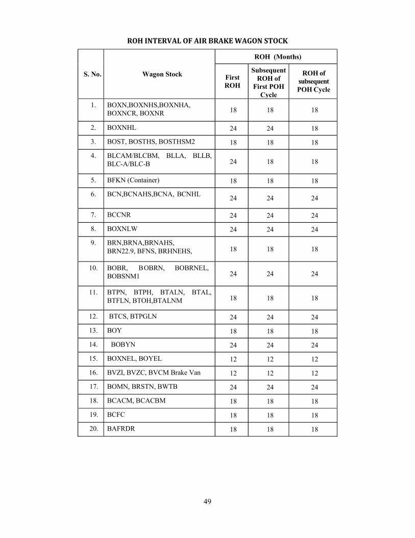
49
ROH INTERVAL OF AIR BRAKE WAGON STOCK
S. No. Wagon Stock
ROH (Months)
First ROH
Subsequent ROH of
First POH Cycle
ROH of subsequent POH Cycle
1. BOXN,BOXNHS,BOXNHA, BOXNCR, BOXNR 18 18 18
2. BOXNHL 24 24 18
3. BOST, BOSTHS, BOSTHSM2 18 18 18
4. BLCAM/BLCBM, BLLA, BLLB, BLC-A/BLC-B 24 18 18
5. BFKN (Container) 18 18 18
6. BCN,BCNAHS,BCNA, BCNHL 24 24 24
7. BCCNR 24 24 24
8. BOXNLW 24 24 24
9. BRN,BRNA,BRNAHS, BRN22.9, BFNS, BRHNEHS, 18 18 18
10. BOBR, BOBRN, BOBRNEL, BOBSNM1 24 24 24
11. BTPN, BTPH, BTALN, BTAL, BTFLN, BTOH,BTALNM 18 18 18
12. BTCS, BTPGLN 24 24 24
13. BOY 18 18 18
14. BOBYN 24 24 24
15. BOXNEL, BOYEL 12 12 12
16. BVZI, BVZC, BVCM Brake Van 12 12 12
17. BOMN, BRSTN, BWTB 24 24 24
18. BCACM, BCACBM 18 18 18
19. BCFC 18 18 18
20. BAFRDR 18 18 18
50
ROH OF BLC WAGON
A routine overhaul should be given to all wagons as a unit of 5 wagons (car A-2, car B-3) at nominated depot at intervals of 18 months. (Newly built 24 months)
Disconnect 5 car units in to separate individual cars. Each car required to undergo ROH individually. The important points generally to looks into are given below for ready reference. Other details of ROH procedures as per RDSO instructions for ROH on wagons should also be looked into. 1. Remove bogie brake rigging attachments to under frames, break gears & flexible pipes
connected to VTA. 2. Remove centre pivot split pin, lock pin and shackle lock etc. 3. Lift the body through lifting pads. Run out the bogie. 4. Clearance of 16 mm between load sensing device sensing tip to stopper are required to be
maintained within tolerance of ± 1mm. 5. Place the under frame on trestles. 6. After removing the side frame key and lifting the bogie remove wheel sets from the bogie.
Machine the wheel tread of all the wheels to worn wheel trade profiles. 7. Strip the bogie. After proper cleaning, examine the bogie side frames, bolster and other
castings for cracks etc. 8. All the side bearers’ liners of the spigot and hole should be replaced. The procedure for
attending the repairs of bogie frames, bolster and liners should be as per instructions. 9. Check bolsters springs and side bearer’s springs for defective/broken springs. Replace the
defective one such that variation in the free height of springs in the same group not to exceed 2mm.
10. Examine center pivot, center pivot pin, center pivot liner. 11. Strip brake gear fittings and examine for wear and damage and serviceability of bogie brake
gear levers, replace worn out bushes and pins. 12. Examine the load sensing device on bogie with air brake in respect of item 5. 13. Replace all the worn out brake blocks and repair worn out brake heads. 14. Check the roller bearings for grease leakages and check adapter and replace if found any
defect. 15. Reset the load sensing valve on bogie and tack weld the fasteners after setting with the
necessary gap (16mm) between tip and stopper as mentioned. 16. Examine under frame brake gear levers; replace worn out bushes and pins. 17. Examine slack adjuster (SAB) and replace or attend to the defects as per RDSO instructions
G-92. After fitment set the SAB “A” dimensions 72 with +0 and – 2 mm. 18. Checkup hand brake arrangement for repair. Replace the missing or damage parts.
Lubricate the gears. 19. Lower the under frame on bogies and provide pivot pin shackle, pin with split pin and connect
brake gear pin. Dimensions 60 with +0 and -0.5 mm between center pivot top to side bearer top liner should be maintained.
20. Test air brakes as per G-97 RDSO instructions. 21. Check automatic locks. Replace the defective locks. Check welding failures. Check automatic
locks for any damage to lock head and for rotation of head. Change the lock head and rubber spring of locks.
22. Check the distance from side frame top liner to side bearer seat 131 with +0 and -0.5 mm at all four side bearer points under tare conditions of the flat wagons. Keep the distance within tolerance by altering shims provided at the top side bearer locations.
23. Ensure all APD (anti pilferage devices) measures are incorporated after assembly. 24. Paint the bogie, stencil station code and date of ROH. 25. Touch up pain and lettering. 26. Special instructions: The draw bar height and CBC height should not be more than 845 mm
and 1105 mm respectively. No packing is given over axle box adapter.
The following items must be attended to during ROH of BLC rakes: 1. Ultrasonic testing of axles.

51
2. Wheel treads profiling. 3. Side bearer liner renewal for spigot and base. 4. Wide jaw adapter renewal/replacement. 5. Side frame repair/ building up at location of adapter. 6. Brake beam (truss bar) pocket liner replacement/ rotation.
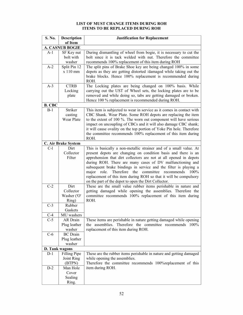
52
LIST OF MUST CHANGE ITEMS DURING ROH ITEMS TO BE REPLACED DURING ROH
S. No. Description
of Item Justification for Replacement
A. CASNUB BOGIE A-1 SF Key nut
bolt with washer
During dismantling of wheel from bogie, it is necessary to cut the bolt since it is tack welded with nut. Therefore the committee recommends 100% replacement of this item during ROH
A-2 Split Pin 12 x 110 mm
The split pins of Brake Shoe key are being changed 100% in some depots as they are getting distorted /damaged while taking out the brake blocks. Hence 100% replacement is recommended during ROH.
A-3 CTRB Locking
plate
The Locking plates are being changed on 100% basis. While carrying out the UST of Wheel sets, the locking plates are to be removed and while doing so, tabs are getting damaged or broken. Hence 100 % replacement is recommended during ROH.
B. CBC B-1 Striker
casting Wear Plate
This item is subjected to wear in service as it comes in contact with CBC Shank. Wear Plate. Some ROH depots are replacing the item to the extent of 100 %. The worn out component will have serious impact on uncoupling of CBCs and it will also damage CBC shank; it will cause ovality on the top portion of Yoke Pin hole. Therefore the committee recommends 100% replacement of this item during ROH.
C. Air Brake System C-l Dirt
Collector Filter
This is basically a non-metallic strainer and of a small value. At present depots are changing on condition basis and there is an apprehension that dirt collectors are not at all opened in depots during ROH. There are many cases of DV malfunctioning and subsequent brake bindings in service and the filter is playing a major role. Therefore the committee recommends 100% replacement of this item during ROH so that it will be compulsory on the part of the depot to open the Dirt Collector.
C-2 Dirt Collector
Washer ('O' Ring)
These are the small value rubber items perishable in nature and getting damaged while opening the assemblies. Therefore the committee recommends 100% replacement of this item during ROH.
C-3 Rubber Gaskets
C-4 MU washers C-5 AR Drain
Plug leather washer
These items are perishable in nature getting damaged while opening the assemblies. Therefore the committee recommends 100% replacement of this item during ROH.
C-6 BC Drain Plug leather
washer D. Tank wagons
D-1 Filling Pipe Joint Ring (BTPN)
These are the rubber items perishable in nature and getting damaged while opening the assemblies. Therefore the committee recommends 100%replacement of this item during ROH. D-2 Man Hole
Cover Sealing Ring.
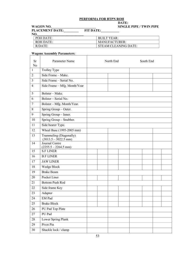
53
PERFORMA FOR BTPN ROH DATE:
WAGON NO.___________________________ SINGLE PIPE / TWIN PIPE PLACEMENT DATE:_________ FIT DATE:___________ NO.____________________________
POH DATE: BUILT YEAR: ROH DATE: MANUFACTURER: R/DATE: STEAM CLEANING DATE:
Wagons Assembly Parameters:
Sr No
Parameter Name North End South End
1 Trolley Type
2 Side Frame – Make.
3 Side Frame – Serial No.
4 Side Frame – Mfg. Month/Year
5 Bolster – Make.
6 Bolster – Serial No.
7 Bolster – Mfg. Month/Year.
8 Spring Group – Outer.
9 Spring Group – Inner.
10 Spring Group – Snubber.
11 Side bearer Type.
12 Wheel Base (1995-2005 mm)
13 Trammeling (Diagonally) (3013.5 – 3022.5 mm)
14 Journal Centre (2255.5 – 2264.5 mm)
15 S.F LINER
16 B.F LINER
17 JAW LINER
18 Wedge Block
19 Brake Beam
20 Pocket Liner
21 Bottom Push Rod
22 Side frame Key
23 Adapter
24 EM Pad
25 Brake Block
26 PU Pad Top Plate
27 PU Pad
28 Lower Spring Plank
29 Pivot Pin
30 Shackle lock / clamp
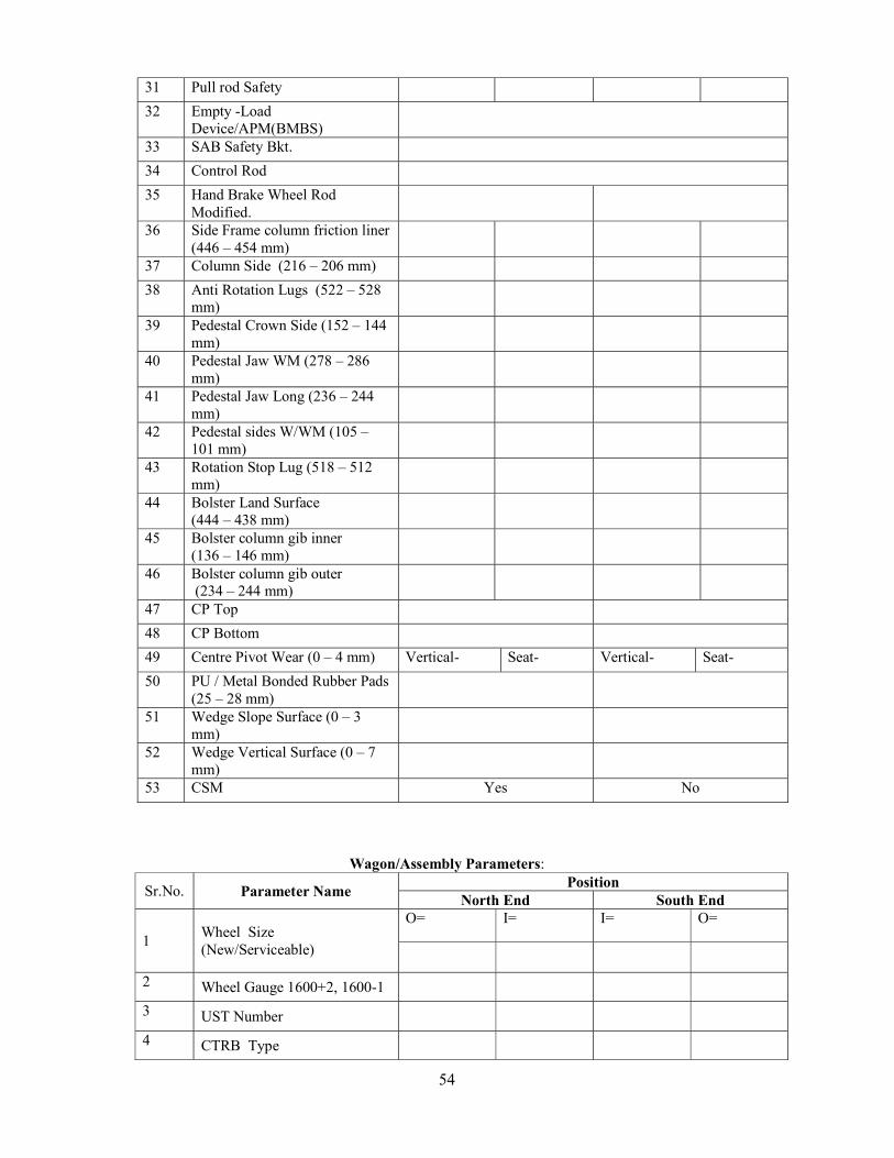
54
31 Pull rod Safety
32 Empty -Load Device/APM(BMBS)
33 SAB Safety Bkt.
34 Control Rod
35 Hand Brake Wheel Rod Modified.
36 Side Frame column friction liner (446 – 454 mm)
37 Column Side (216 – 206 mm)
38 Anti Rotation Lugs (522 – 528 mm)
39 Pedestal Crown Side (152 – 144 mm)
40 Pedestal Jaw WM (278 – 286 mm)
41 Pedestal Jaw Long (236 – 244 mm)
42 Pedestal sides W/WM (105 – 101 mm)
43 Rotation Stop Lug (518 – 512 mm)
44 Bolster Land Surface (444 – 438 mm)
45 Bolster column gib inner (136 – 146 mm)
46 Bolster column gib outer (234 – 244 mm)
47 CP Top
48 CP Bottom
49 Centre Pivot Wear (0 – 4 mm) Vertical- Seat- Vertical- Seat-
50 PU / Metal Bonded Rubber Pads (25 – 28 mm)
51 Wedge Slope Surface (0 – 3 mm)
52 Wedge Vertical Surface (0 – 7 mm)
53 CSM Yes No
Wagon/Assembly Parameters:
Sr.No. Parameter Name Position
North End South End
1 Wheel Size (New/Serviceable)
O= I= I= O=
2 Wheel Gauge 1600+2, 1600-1
3 UST Number
4 CTRB Type
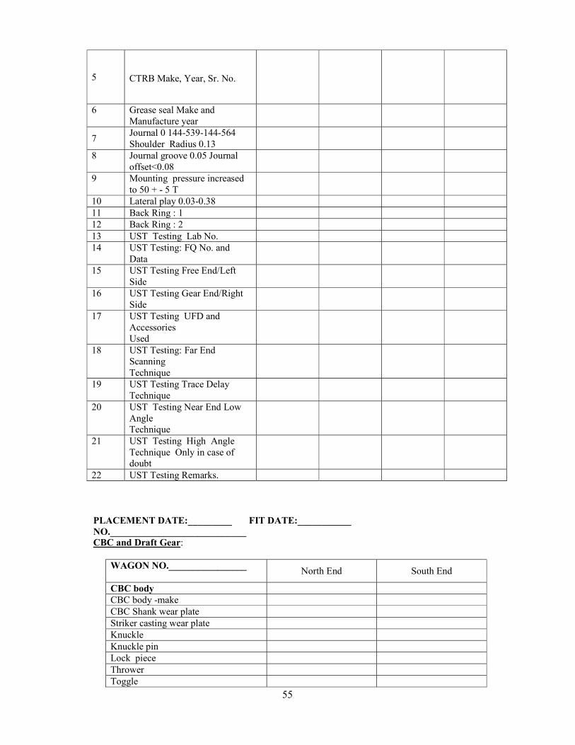
55
5
CTRB Make, Year, Sr. No.
6 Grease seal Make and Manufacture year
7 Journal 0 144-539-144-564 Shoulder Radius 0.13
8 Journal groove 0.05 Journal offset<0.08
9 Mounting pressure increased to 50 + - 5 T
10 Lateral play 0.03-0.38 11 Back Ring : 1 12 Back Ring : 2 13 UST Testing Lab No. 14 UST Testing: FQ No. and
Data
15 UST Testing Free End/Left Side
16 UST Testing Gear End/Right Side
17 UST Testing UFD and Accessories Used
18 UST Testing: Far End Scanning Technique
19 UST Testing Trace Delay Technique
20 UST Testing Near End Low Angle Technique
21 UST Testing High Angle Technique Only in case of doubt
22 UST Testing Remarks. PLACEMENT DATE:_________ FIT DATE:___________ NO.____________________________ CBC and Draft Gear:
WAGON NO.________________
North End South End
CBC body CBC body -make CBC Shank wear plate Striker casting wear plate Knuckle Knuckle pin Lock piece Thrower Toggle
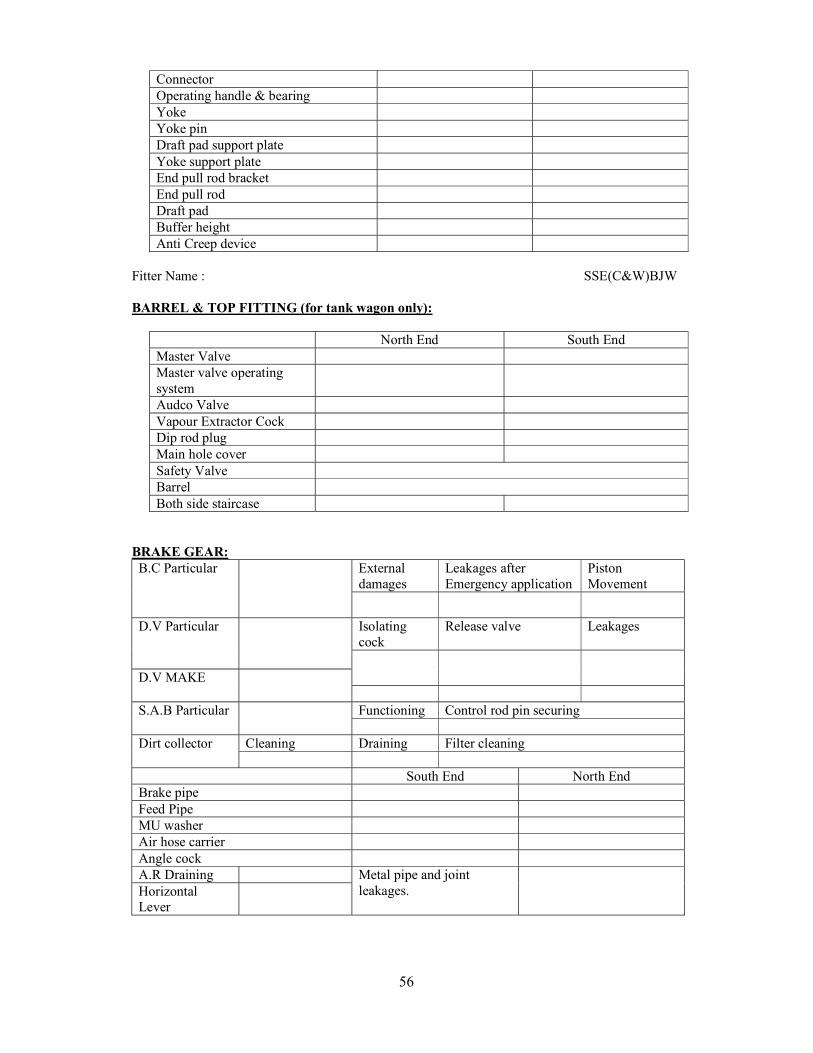
56
Connector Operating handle & bearing Yoke Yoke pin Draft pad support plate Yoke support plate End pull rod bracket End pull rod Draft pad Buffer height Anti Creep device
Fitter Name : SSE(C&W)BJW BARREL & TOP FITTING (for tank wagon only):
North End South End Master Valve Master valve operating system
Audco Valve Vapour Extractor Cock Dip rod plug Main hole cover Safety Valve Barrel Both side staircase
BRAKE GEAR: B.C Particular External
damages Leakages after Emergency application
Piston Movement
D.V Particular Isolating cock
Release valve Leakages
D.V MAKE
S.A.B Particular Functioning Control rod pin securing
Dirt collector Cleaning Draining Filter cleaning
South End North End Brake pipe Feed Pipe MU washer Air hose carrier Angle cock A.R Draining Metal pipe and joint
leakages.
Horizontal Lever
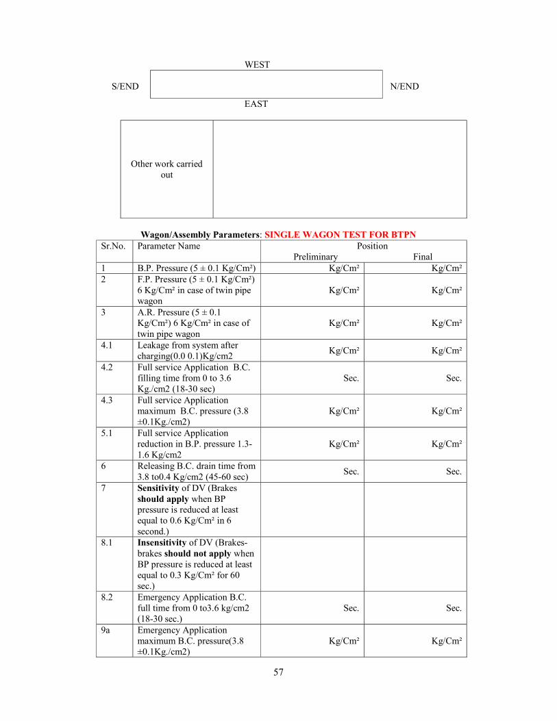
57
WEST S/END N/END
EAST
Other work carried out
Wagon/Assembly Parameters: SINGLE WAGON TEST FOR BTPN
Sr.No. Parameter Name Position Preliminary Final
1 B.P. Pressure (5 ± 0.1 Kg/Cm²) Kg/Cm² Kg/Cm² 2 F.P. Pressure (5 ± 0.1 Kg/Cm²)
6 Kg/Cm² in case of twin pipe wagon
Kg/Cm² Kg/Cm²
3 A.R. Pressure (5 ± 0.1 Kg/Cm²) 6 Kg/Cm² in case of twin pipe wagon
Kg/Cm² Kg/Cm²
4.1 Leakage from system after charging(0.0 0.1)Kg/cm2
Kg/Cm² Kg/Cm²
4.2 Full service Application B.C. filling time from 0 to 3.6 Kg./cm2 (18-30 sec)
Sec. Sec.
4.3 Full service Application maximum B.C. pressure (3.8 ±0.1Kg./cm2)
Kg/Cm² Kg/Cm²
5.1 Full service Application reduction in B.P. pressure 1.3-1.6 Kg/cm2
Kg/Cm² Kg/Cm²
6 Releasing B.C. drain time from 3.8 to0.4 Kg/cm2 (45-60 sec)
Sec. Sec.
7 Sensitivity of DV (Brakes should apply when BP pressure is reduced at least equal to 0.6 Kg/Cm² in 6 second.)
8.1 Insensitivity of DV (Brakes-brakes should not apply when BP pressure is reduced at least equal to 0.3 Kg/Cm² for 60 sec.)
8.2 Emergency Application B.C. full time from 0 to3.6 kg/cm2 (18-30 sec.)
Sec. Sec.
9a Emergency Application maximum B.C. pressure(3.8 ±0.1Kg./cm2)
Kg/Cm² Kg/Cm²
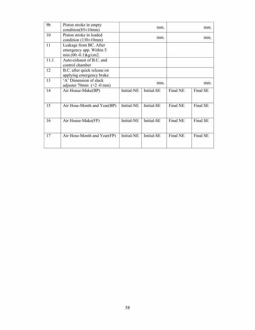
58
9b Piston stroke in empty condition(85±10mm)
mm. mm.
10 Piston stroke in loaded condition (130±10mm)
mm. mm.
11 Leakage from BC. After emergency app. Within 5 min.(00.-0.1)kg/cm2.
11.1 Auto-exhaust of B.C. and control chamber
12 B.C. after quick release on applying emergency brake
13 ‘A’ Dimension of slack adjuster 70mm (+2 -0 mm)
mm. mm.
14 Air House-Make(BP) Initial-NE
Initial-SE Final NE Final SE
15 Air Hose-Month and Year(BP) Initial-NE
Initial-SE Final NE Final SE
16 Air House-Make(FP) Initial-NE
Initial-SE Final NE Final SE
17 Air Hose-Month and Year(FP) Initial-NE
Initial-SE Final NE Final SE
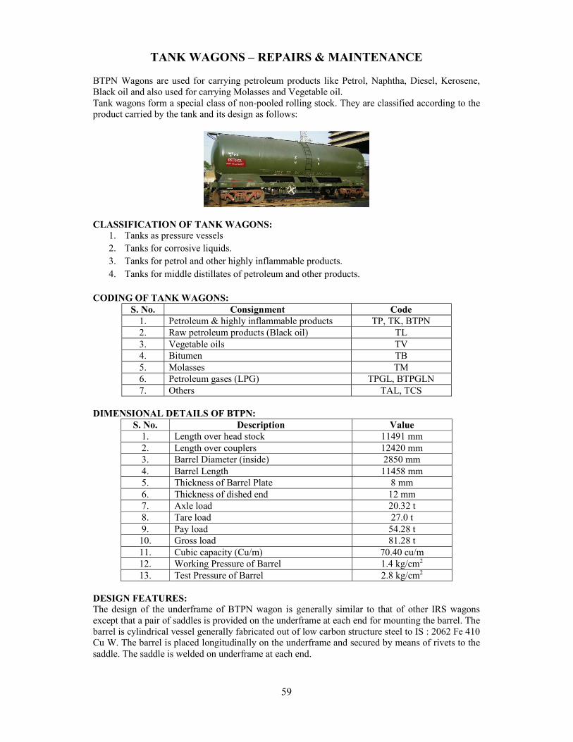
59
TANK WAGONS – REPAIRS & MAINTENANCE
BTPN Wagons are used for carrying petroleum products like Petrol, Naphtha, Diesel, Kerosene, Black oil and also used for carrying Molasses and Vegetable oil. Tank wagons form a special class of non-pooled rolling stock. They are classified according to the product carried by the tank and its design as follows:
CLASSIFICATION OF TANK WAGONS:
1. Tanks as pressure vessels 2. Tanks for corrosive liquids. 3. Tanks for petrol and other highly inflammable products. 4. Tanks for middle distillates of petroleum and other products.
CODING OF TANK WAGONS:
S. No. Consignment Code 1. Petroleum & highly inflammable products TP, TK, BTPN 2. Raw petroleum products (Black oil) TL 3. Vegetable oils TV 4. Bitumen TB 5. Molasses TM 6. Petroleum gases (LPG) TPGL, BTPGLN 7. Others TAL, TCS
DIMENSIONAL DETAILS OF BTPN:
S. No. Description Value 1. Length over head stock 11491 mm 2. Length over couplers 12420 mm 3. Barrel Diameter (inside) 2850 mm 4. Barrel Length 11458 mm 5. Thickness of Barrel Plate 8 mm 6. Thickness of dished end 12 mm 7. Axle load 20.32 t 8. Tare load 27.0 t 9. Pay load 54.28 t 10. Gross load 81.28 t 11. Cubic capacity (Cu/m) 70.40 cu/m 12. Working Pressure of Barrel 1.4 kg/cm2 13. Test Pressure of Barrel 2.8 kg/cm2
DESIGN FEATURES: The design of the underframe of BTPN wagon is generally similar to that of other IRS wagons except that a pair of saddles is provided on the underframe at each end for mounting the barrel. The barrel is cylindrical vessel generally fabricated out of low carbon structure steel to IS : 2062 Fe 410 Cu W. The barrel is placed longitudinally on the underframe and secured by means of rivets to the saddle. The saddle is welded on underframe at each end.
60
BARREL MOUNTINGS: S. No. Mountings/Fittings Function 1. Safety valve The safety valve is provided to prevent building up of excess
pressure inside the barrel. It is fitted on the barrel either on the diaphragm plate inside the dome or on a separate opening on the barrel. This is provided on highly inflammable liquid such as petrol., aviation sprit .etc.
2. Relief valve It is a spring loaded valve fitted on the barrel on tanks for corrosive liquids. Its main function is to release built up pressure, if it exceeds the working pressure limit.
3. Safety vent This consists of frangible disc (lead or any approved material not affected by loading), which ruptures at specified pressure. It is an additional safety fitting to safeguard against the failure of the relief valve. When the built up pressure exceed the working pressure of the relief valve and the latter fails to function for any reason the frangible disc of this safety vent ruptures to release the pressure.
4. Compressed air valve
It is provided on tank from which the contents are unloaded by compressed air. Its main function is to control the rate of discharge by controlling the rate of air admission.
5. Vapour Extractor Cock
Its function is to extract vapour from the tank while filling.
6. Master valve It is a gravity discharge valve fitted with a hand wheel in the dome for manual operation.
7. Bottom discharge valve
BG-4 wheeler Bottom discharge valve are provided with the single bottom discharge valve situated underneath the master valve while on BG/MG -8 wheeler stock two bottom discharge valve are fitted one on either side and connected with the master valve through a ‘T’ pipe. The main function of the valve is to control the flow of the contents and also to serve as an additional safety stock in case the master valve fails or breaks. The bottom discharge valve opening are also provided with blank flanges to be used with 2mm compressed asbestos fibre jointing material to serve as further check on accidental leakage of contents.
The periodicity of POH is given as:
S. No. Type of wagons For I POH For subsequent POH 1. BTPH 4.5 4.5 2. BTPN 6 6 3. BTPGLN, BTCS 4 4 4. BTALN, BTALNM 4.5 4.5 5. BTFLN, BTOH 6 6
The codal life of tank wagons is 40 years. Steam cleaning for pressure vessels, petroleum and other highly inflammable products: Tanks as pressure vessels, tanks for petroleum, other highly inflammable products, vegetable oils, bitumen, coal tar and molasses are cleaned by steam. The tanks requiring steam cleaning should be placed as near the steam supply line as possible and protected against any movement. The berthing siding should be completely isolated from all other traffic. In case of pressure vessels, it should be ensured that all the gas has been discharged to the atmosphere. After ensuring that the tank barrel is no longer under pressure, the following sequence should be followed:
61
Remove the manhole cover together with manhole housing, valves etc. and leave the tank exposed to atmosphere for 24 hours.
Entry of staff in the tank barrel should be strictly prohibited and signs with suitable legends displayed at a reasonable distances away from the tanks to be steam cleaned.
Insert pipe through manhole and steam the interior of barrel for 12 hours.
In order that the tank barrel is thoroughly steamed from inside, the steam pipe should be provided with a “T” connection at its lower end and so directed as to blow steam towards both ends.
Remove condensed steam collected in the tank barrel and keep the barrel exposed to atmosphere for another 24 hours.
The following are the tests that should be conducted to ensure the tanks are free from contamination gases of the contents.
AMMONIA TANK BARREL: Fill the tank barrel with water. Collect a specimen of the water in a clean glass bottle. Test the specimen of the water with red litmus paper. If the colour of the litmus paper turns into blue, it indicates that the barrel is still having the gases of ammonia and requires steam cleaning.
NESSLER’S TEST: Test the specimen of the water with a mixture of potassium mercuric iodide and potassium hydroxide. If the colour of the mixture turns into brown, it indicates that the barrel is still having the gases of ammonia and requires steam cleaning.
CHLORINE TANK WAGONS: Fill the tank barrel with water. Collect a specimen of the water in a clean glass bottle. Test the specimen of the water with red litmus paper. If there is any bleaching effect on the litmus paper, it indicates that the barrel is still having the gases of chlorine and requires steam cleaning.
LPG TANK WAGONS: Fill fresh water in a clean bottle. A string is to be attached to the bottom of the bottle. Lower the bottle through the manhole up to the bottom of the tank and tilt the bottle. Allow the water to flow out and let the gas get into the bottle. Wait for 5 minutes and lift the bottle and close the mouth immediately after withdrawing. Take it away from the tank. Bring a lighted matchstick near the mouth of the bottle after opening it. If there is no flame it is free from injurious gas. But in case it gives out a flame, the tank should again be steam cleaned again.
Procedure for steam cleaning of bitumen and molasses tank wagons: Close the manhole cover and open bottom discharge valve. Pass steam through the air inlet valve for sufficient time till the bitumen melts and drains away through the water discharge valve. The bitumen should be collected in containers and not drained out on the floor. Open the manhole cover to see whether the tank is completely cleaned from inside. In case any residue is left behind the above procedure should be repeated. Remove heating arrangement i.e., heating pipe, internal pipe, etc, from the tank. Clean inside surface of the heating pipe by scrapping the carbon layer with wire brush or other suitable process. Blow in air under pressure from one end. The outer surface of the heating pipe should be cleaned with kerosene oil. Procedure for cleaning of tanks for corrosive liquids:
HYDROCHLORIC ACID TANKS: Open the manhole and the washout cover and start cleaning the barrel with water. Initially the water coming out of the washout opening will show excessive acidity, which will turn blue litmus paper into red. The washing should be continued till blue litmus paper shows no change. Then close the wash out cover, fill the tank with water. Collect a sample of the water in a bottle. Test the sample of water with blue litmus paper. If the colour is changing to red, it indicates that the tank is still having traces of acid and requires cleaning.
62
SULPHURIC ACID TANKS: Wash the Sulphuric acid tank barrels with ½ % to 1% solution of sodium phosphate commercial or half percent solution of soda ash so as to neutralize the sulphuric acid. The washing should be done as soon as it is received in workshops. Since concentrated sulphuric acid absorbs moisture when left open to moist air, the acid will be diluted with time. It is to be remembered that diluted sulphuric acid is highly corrosive and attacks the tank barrel more vigorously. Collect a sample of water in a bottle. Test with blue litmus paper. If the colour of the paper changes into red, it indicates that tank is having still traces of acid and requires cleaning again. After cleaning allow the tank for drying.
Caution: As addition of water to sulphuric acid will produce intense heat, resulting in splashing of steam, the solution of commercial sodium phosphate should be added or spread gradually and with care.
CAUSTIC SODA TANKS: Wash the barrels with hot water. Freedom from alkalinity can
be easily ascertained by litmus test (if red Litmus changes to blue, there are still traces of alkalinity). After it is free from alkalinity, water should be drained and barrel dried before inspection and repairs.
Checks to be carried out by the C&W Engineers before the tank wagon is certified for loading:
Master Valve: Leakage of master valve should be checked while keeping the bottom discharged valve in open.
Bottom discharge Valve: Proper functioning and fluid tightness of the bottom discharge Valve should be ensured.
Blank flange: The blank flange of the correct thickness made out of steel plate and with a gasket of proper material between the blank flange and bottom discharge valve flange should be tightened by six bolts and nuts.
Tank barrel: Tanks with cracks on barrels should be marked sick.
Leaky Tank barrels: The leakage of tank barrels may be caused due to the following reasons. Mechanical injury to the valve face and /or valve seat as a result of foreign material, particularly nuts and bolts finding their way inside the tank wagon, valves seat not properly secured to the stool by proper interference fits and malfunctioning of master valve.
Precautions in the case of leakage from the loaded tank wagons:
CHLORINE & AMMONIA tanks: Chlorine and ammonia gases are poisonous and have a characteristic pungent odour, which gives warning of their presence in the atmosphere before dangerous concentrations are attained. In the case of chlorine, the greenish yellow colour of the gas makes it visible when high concentrations are present. In the case of ammonia, if sufficient concentration of the gas is present in the atmosphere, it will irritate the eyes and the respiratory system. As such, in the event of leakage, all present in the vicinity should be warned to keep on the windward side of the tank.
HIGHLY INFLAMMABLE GAS tanks: All the flames or fires near it should be
extinguished or removed. Smoking should not be allowed. Spectators should be kept away. Only battery operated torches or incandescent electric lights with gas proof sockets should be used. Oil lanterns or signal lamps used for signalling must be kept away. The steam engine available if any should be moved away from the site. The leaky tank wagon should be removed as quickly as possible to an open area, where the escaping gas will be less
63
hazardous. Earth should be spread over any surface on which the LPG has leaked out in liquid form. Call the company concerned for further attention.
PROCEDURE FOR LOADING/UNLOADING:
Before loading the wagon must be certified fit for loading by the TXR. Instructions issued by the Board/Railways from time to time in this regard should be religiously followed.
The wagons to be loaded/unloaded are placed in position preferably under shed and hand brake are applied to prevent any movement.
It should be ensured that points leading to loading/unloading line on which the wagons are to be loaded/unloaded are set and pad locked so as to isolate the line on which the loading/unloading are to be done.
Shunting of wagons are not permitted on the same line when loading/unloading is done.
Throughout the entire period of transfer operation, the wagon must be continuously attended to by the operator.
PRECAUTION TO BE TAKEN AT LOADING POINTS:
Ensure that all tank fittings are in good working condition. Ensure that the master valve is fluid tight.
Ensure that the bottom discharge valve is fully closed and fitted with a blank flange and gasket before commencement.
Ensure that the vapour extractor cock and vent plug are open before commencement of loading.
Ensure that loading is done through the filling pipe only.
Ensure that recommended air space as specified for the particular petroleum product is provided and that payload does not exceed the permissible limit.
Provide proper sealing when dome cover eye bolt nuts are tightened.
Make sure that the dome cover is closed after loading.
64
AIR BRAKE SYSTEM IN WAGON
CLASSIFICATION OF AIR BRAKE SYSTEM:- On the basis of type of release, air brake system is classified as:
Direct release air brake system Graduated release air brake system
Both Direct and Graduated release are further available in two forms viz.
Single pipe and Twin pipe
PRINCIPLE OF OPERATION OF TWIN PIPE GRADUATED RELEASE AIR BRAKE SYSTEM:- Some of the Air Brake goods stock on IR is fitted with Twin pipe graduated release air brake system. In Twin pipe, brake pipes and feed pipes of all wagons are connected. Also all the cut off angle cocks are kept open except the front cut off angle cocks of BP/ FP of leading loco and rear end cut off angle cock of BP and FP of last vehicle. Isolating cocks on all wagons are also kept in open condition. Auxiliary reservoir is charged to 6.0 Kg/cm2 through the feed pipe. A. CHARGING STAGE During this stage, brake pipe is charged to 5 kg/cm2 pressure and feed pipe is charged to 6 kg/cm2 pressure which in turn charges control reservoir and auxiliary reservoir to 6 kg/cm2 pressure. At this stage, brake cylinder gets vented to atmosphere through passage in Distributor valve. B. APPLICATION STAGE For application of brakes, the pressure in brake pipe has to be dropped. This is done by venting air from driver’s brake valve. Reduction in brake pipe pressure positions the distributor valve in such a way that the control reservoir gets disconnected from brake pipe and auxiliary reservoir gets connected to brake cylinder. This results in increase in air pressure in brake cylinder resulting in application of brakes. The magnitude of braking force is proportional to reduction in brake pipe pressure Note: 1. Brake Application takes places when Brake pipe pressure is dropped. 2. The drop of pressure may be a) Intentional and b) Accidental. C. RELEASE STAGE For releasing brakes, the brake pipe is again charged to 5 kg/cm2 pressure by compressor through driver’s brake valve. This action positions distributor valve in such a way that auxiliary reservoir gets isolated from brake cylinder and brake cylinder is vented to atmosphere through distributor valve and thus brakes are released. Do’s and Don’ts for Twin Pipe working of Freight Trains DO’s:
1. Do ensure that the all twin pipe Wagons are operated in CC rakes only 2. Do ensure that loco provided for twin pipe rake is having its twin pipe in working
condition. 3. Do ensure availability of spare pool of twin pipe wagon & brake van, for replacement, if
required. 4. Do ensure availability of spare feed pipe in loco. 4. Do ensure that brake van provided for twin pipe working is having twin pipe system. 5. Do ensure BP coupling heads are marked with ‘BP’ and painted in green. 6. Do ensure FP coupling heads are marked with ‘FP’ and painted in white. 7. Do ensure that BP & FP hose couplings at the rear end of the train are placed on their
respective hose coupling supports. 8. Do ensure that pressure gauges for BP and FP are provided in the brake van. 9. Do ensure that brake pipe/feed pipe angle cocks are not closed under any circumstance,
either for isolation of wagons or for any purpose whatsoever, except for carrying out
65
shunting operation, after which the angel cocks should again be opened to ensure continuity of brake pipe and feed pipe.
10. Do ensure that the isolating cock of feed pipe of all the wagons in the open position. The handle of cock shall be vertically down when open and at horizontal when closed.
11. Do ensure that gauge in guards compartment show pressure not less than 5.8 kg/cm2 in feed pipe after the system is fully charged.
12. Do ensure that feed pipe hose coupling are connected to form a continuous passage from locomotive to last vehicle.
13. Do ensure that feed pipe Cut off angle cocks, except at the rear of train, are kept open. 14. Do ensure availability of the quick coupling for attaching and detaching the pressure gauges
for BP/FP in brake van.
DON’Ts: 1. Do not allow single pipe coupling. 2. Do not allow a feed pipe to be connected to the brake pipe anywhere in the train or vice
versa. 3. Do not allow a feed pipe hose coupling at rear end to dangle. 4. Do not allow train to leave with leakage higher than specified. 5. 5. Do not allow train to leave with feed pipe pressure in loco and brake van less than
specified. MARKING OF TWIN PIPE AIR BRAKE FITTED WAGONS For easy identification of these wagons, ‘Twin Pipe’ written in black letters on yellow background and encircled in white band shall be marked on side panel, one side in English and other side in Hindi as specified in RDSO drawings. AIR BRAKE TESTING OF RAKES HAVING TWIN PIPE BRAKE SYSTEM RAKE TEST : A rake of wagon stock can be tested with this Test Rig. This Rig may also be used for testing the train in yards before attaching the engine. The Rake Test Rig unit has air supply and mobile test rig. The mobile test rig is having a cubical structure and is mounted on wheels. It can be taken to the yards and sick lines. The procedure is as follows:
a. Carry out Visual Examination of rake. b. Prepare Test Rig for Rake Test. c. Conduct Leakage, Service Application and Release Test.
Visual inspection is a check of air brake sub-assembly for any damage on the brake pipe, hose coupling etc and then rectifying it. The steps are :-
i) Inspect loose suspension brackets and anti-pilferage devices of all air brake subassemblies.
ii) Visually inspect for any defect/damage in the brake pipe, hose pipe, coupling etc. iii) Rectify or replace the problematic part/sub-assembly.
Rake Test can be performed by using a portable device called ‘Test Rig’ or by Locomotive. The Test Rig provides all facilities like locomotive to conduct the test. The source of compressed air supply to the Test Rig is through a compressor installed in the wagon depot for Brake Pipe and Feed Pipe of the test rig. The Air Dryer should also be provided just before connecting brake pipe and feed pipe for supply of dry air.
Attach the rake test rig to the rake through the couplings. Carry out following tests as per the procedure given in G-97 Annexure-XI {MP guide No.11 (Rev.01) amendment No.01 of Jan-2010} for checking capability of locomotives for Charging/Releasing of train brakes, checking of leakage in the train, checking leakage in feed pipe, brake cylinder operative percentage, and procedure to be followed at way side.
Note: In case rake test rig is not available testing shall be done by locomotive.
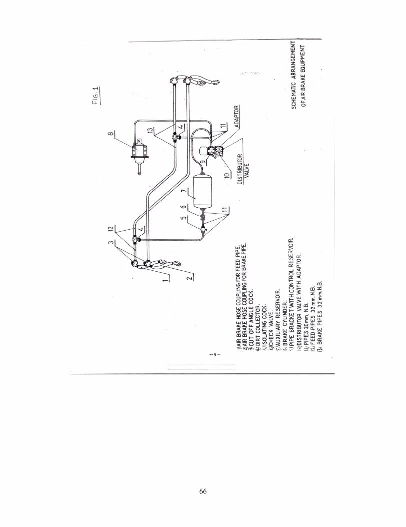
66
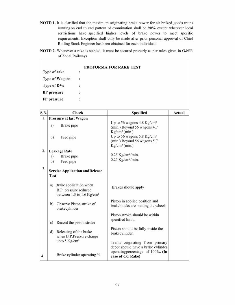
67
NOTE:1. It is clarified that the maximum originating brake power for air braked goods trains running on end to end pattern of examination shall be 90% except wherever local restrictions have specified higher levels of brake power to meet specific requirements. Exception shall only be made after prior personal approval of Chief Rolling Stock Engineer has been obtained for each individual.
NOTE:2. Whenever a rake is stabled, it must be secured properly as per rules given in G&SR of Zonal Railways.
PROFORMA FOR RAKE TEST
Type of rake :
Type of Wagons :
Type of DVs :
BP pressure :
FP pressure :
S.N. Check Specified Actual 1. 2. 3.
4.
Pressure at last Wagon
a) Brake pipe
b) Feed pipe Leakage Rate a) Brake pipe b) Feed pipe
Service Application and Release Test a) Brake application when
B.P. pressure reduced between 1.3 to 1.6 Kg/cm²
b) Observe Piston stroke of
brake cylinder c) Record the piston stroke
d) Releasing of the brake
when B.P. Pressure charge upto 5 Kg/cm²
Brake cylinder operating %
Up to 56 wagons 4.8 Kg/cm² (min.) Beyond 56 wagons 4.7 Kg/cm² (min.) Up to 56 wagons 5.8 Kg/cm² (min.) Beyond 56 wagons 5.7 Kg/cm² (min.)
0.25 Kg/cm²/min. 0.25 Kg/cm²/min.
Brakes should apply
Piston in applied position and brake blocks are matting the wheels
Piston stroke should be within specified limit. Piston should be fully inside the brake cylinder.
Trains originating from primary depot should have a brake cylinder operating percentage of 100%. (In case of CC Rake)
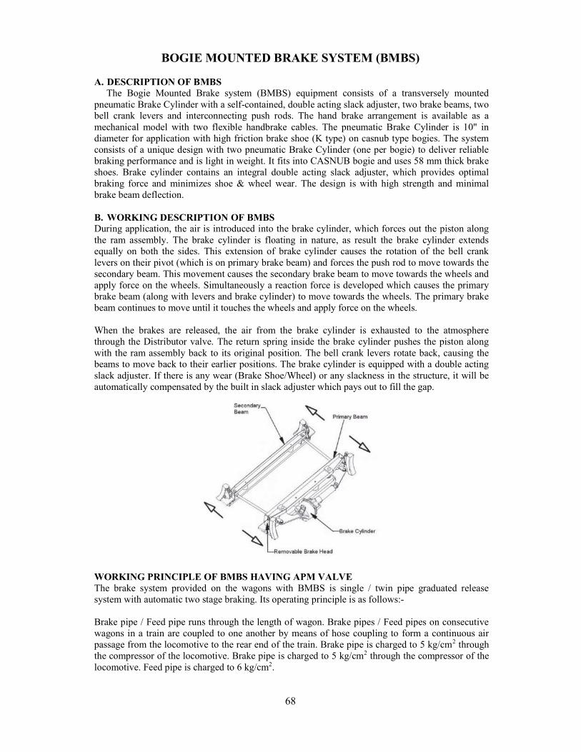
68
BOGIE MOUNTED BRAKE SYSTEM (BMBS)
A. DESCRIPTION OF BMBS The Bogie Mounted Brake system (BMBS) equipment consists of a transversely mounted pneumatic Brake Cylinder with a self-contained, double acting slack adjuster, two brake beams, two bell crank levers and interconnecting push rods. The hand brake arrangement is available as a mechanical model with two flexible handbrake cables. The pneumatic Brake Cylinder is 10" in diameter for application with high friction brake shoe (K type) on casnub type bogies. The system consists of a unique design with two pneumatic Brake Cylinder (one per bogie) to deliver reliable braking performance and is light in weight. It fits into CASNUB bogie and uses 58 mm thick brake shoes. Brake cylinder contains an integral double acting slack adjuster, which provides optimal braking force and minimizes shoe & wheel wear. The design is with high strength and minimal brake beam deflection. B. WORKING DESCRIPTION OF BMBS During application, the air is introduced into the brake cylinder, which forces out the piston along the ram assembly. The brake cylinder is floating in nature, as result the brake cylinder extends equally on both the sides. This extension of brake cylinder causes the rotation of the bell crank levers on their pivot (which is on primary brake beam) and forces the push rod to move towards the secondary beam. This movement causes the secondary brake beam to move towards the wheels and apply force on the wheels. Simultaneously a reaction force is developed which causes the primary brake beam (along with levers and brake cylinder) to move towards the wheels. The primary brake beam continues to move until it touches the wheels and apply force on the wheels. When the brakes are released, the air from the brake cylinder is exhausted to the atmosphere through the Distributor valve. The return spring inside the brake cylinder pushes the piston along with the ram assembly back to its original position. The bell crank levers rotate back, causing the beams to move back to their earlier positions. The brake cylinder is equipped with a double acting slack adjuster. If there is any wear (Brake Shoe/Wheel) or any slackness in the structure, it will be automatically compensated by the built in slack adjuster which pays out to fill the gap.
WORKING PRINCIPLE OF BMBS HAVING APM VALVE The brake system provided on the wagons with BMBS is single / twin pipe graduated release system with automatic two stage braking. Its operating principle is as follows:- Brake pipe / Feed pipe runs through the length of wagon. Brake pipes / Feed pipes on consecutive wagons in a train are coupled to one another by means of hose coupling to form a continuous air passage from the locomotive to the rear end of the train. Brake pipe is charged to 5 kg/cm2 through the compressor of the locomotive. Brake pipe is charged to 5 kg/cm2 through the compressor of the locomotive. Feed pipe is charged to 6 kg/cm2.
69
The wagons are, provided with Automatic pressure modification (APM) device to cater for higher brake power in loaded condition instead of the conventional manual empty load device. With the provision of this, brake cylinder pressure of 2.2 ± 0.25 kg/cm2 is obtained in empty condition and 3.8 ± 0.1 kg/cm2 is obtained in the loaded condition. To obtain this a change over mechanism, APM underframe and side frame of the bogie. The mechanism gets actuated at a pre-determined change over weight of the wagon and changes the pressure going to the brake cylinder from 2.2 ± 0.25 kg/cm2 to 3.8 ± 0.1 kg/cm2 in case of changeover from empty to loaded and vice versa. For application of brake, air pressure in the brake pipe is reduced by venting it to the atmosphere from driver's brake valve in the locomotive. The reduction of the brake pipe pressure, positions the distributor valve in such a way that the auxiliary reservoir is connected to the brake cylinder through the APM device and thereby applying the brake. The distributor valve gives an output pressure of 3.8 kg/cm2 for the brake cylinder which is routed through the APM device. Based on the position of sensor arm of APM device, it gives an output of 2.2 ± 0.25 kg/cm2 for empty position braking and an output of 3.8 ± 0.1 kg/cm2 for loaded position braking in the wagon. During full service brake application, a reduction of 1.3 to 1.6 kg/cm2 takes, a maximum brake cylinder pressure of 3.8 ± 0.1 kg/cm2 in loaded condition and 2.2 ± 0.25 kg/cm2 in empty condition is achieved. Any further reduction of brake pipe pressure has no effect on the brake cylinder pressure. During emergency brake application, the brake pipe is vented to atmosphere very quickly; as a result the distributor valve acquires the full application position also at a faster rate. This result in quicker built up of brake cylinder pressure but the maximum brake cylinder pressure will be the same as that obtained during a full service brake application. For release of brakes, air pressure in the brake pipe is increased through driver's brake valve. The increase in the brake pipe pressure results in exhausting the brake cylinder pressure through the Distributor valve. The decrease in the brake cylinder pressure corresponds to the increase in the brake pipe pressure. When the brake pipe pressure reaches 5 kg/cm2, the brake cylinder pressure exhausts completely and the brakes are completely released.
70
BRAKE BINDING – CAUSES & REMEDIES During release even after the brake pipe pressure is charged to 5 Kg/Cm2, in case of air brake stock or a maximum vacuum is re-created in case of vacuum brake stock, due to various reasons, the brake will not release and thus the wheels will not revolve freely on the track. This phenomenon is called brake binding. The repercussions of brake binding are that it damages the wheels, damages the bearings, gives discomfort to the passengers, leads to detention to the trains, leads to detachment of rolling stock enroute, leads to train parting and high power / fuel consumption. It also damages the track. CAUSES OF BRAKE BINDING: The causes of brake binding can broadly be classified based on the failures in the following;
Brake power creations system (Pneumatic system) Brake power transmission system (Brake rigging)
Brake binding due to defects in Brake power creation system;
Brake power creation system is a system through which the brake power is made available on the piston with the help of compressed air in case of air brake system or with the help of vacuum/ atmospheric pressure in the case of vacuum brake system. All the parts which are available for the passage of compressed air / atmospheric air between loco and the brake cylinder come under the power creation system. Any failure in these parts between loco and the brake cylinders results in brake binding. The main parts coming under power creation system are Brake pipe, Auxiliary reservoir, Control reservoir, Distributor valve, Brake cylinder, Cut off angle cock, Air hoses, Feed pipe etc.
Under normal conditions the BP is charged with 5Kg/Cm2 from the loco. The control reservoir and the auxiliary reservoir are also charged with 5 Kg/Cm2 from BP through distributor valve in case of single pipe system. In case of twin pipe system the auxiliary reservoir is charged to 6 Kg/Cm2 through FP. When the brake pipe pressure is 5 Kg/Cm2 the brake cylinder is connected to exhaust through distributor valve in order to keep the brakes in released position. Whenever the BP is reducing below the CR pressure, the DV will connect auxiliary reservoir to the brake cylinder to apply the brake. Whenever the brake pipe pressure is equal to CR pressure, AR will be disconnected from BC, and in turn BC will be connected to exhaust through distributor valve to release the brake completely. As such, any leakages in the system on run results in reduction of BP pressure, which in turn lead to brake binding due to unintentional brake application. The defects in the power creation system that lead to brake binding are; BP pressure less than 5 Kg/Cm2, CR Pressure is more than BP pressure, defects in the distributor valve, breakage in the pipe connection between DV and BC and leakages in auxiliary reservoir. The reasons for the brake pipe pressure to become less than 5 Kg/Cm2 are Leakages in air hoses, leakage through cut-off angle cocks, dirt collector, brake pipes, Distributor valve particularly at the joints. Leakage through PEAS, Guard Emergency Valve and Auxiliary reservoir. Reasons for CR pressure to become more than BP pressure; Due to the difference in calibration of brake pipe pressure gauges in the locomotives there is a chance of overcharging/under charging of BP pressure during loco change, even though pressure gauges indicates 5 Kg/Cm2 which will result in brake binding throughout the formations due to differential pressures in the incoming/ outgoing locos. Whenever the locos are reversed at the junction stations for lengthy train (58 BOXN wagons) it is not possible for the loco to charge 5 Kg/Cm2 in the rear most vehicle, whereas, CR is already charged with 5 Kg/Cm2 before the reversal of locomotives. This difference of the pressures will cause brake binding in the rear portion of such train.
71
The defects in the distributor valves which causes brake binding are; Exhaust port blocked due to dirt & moisture content. Interchanging of DVs between coach and goods results in excessive release timings. Due to the internal defects in the DV. Breakage in the pipe connection between DV and the brake cylinder leads to excessive leakages of air from AR after the brake application. This excessive leakage drops the MR pressure abruptly. Once MR pressure drops it is not possible to restore the BP pressure to 5 Kg/Cm2 during release, results in brake binding in the entire formation. Remedial measures: - Detect and Isolate the D.V:
In case of single pipe, auxiliary reservoir is charged through brake pipe. Excessive leakage in the AR due to working out of drain plug or corrosion and foreign body hit on the AR, prevents recharging of BP to 5 Kg/Cm2 and results in brake binding on the entire formations. Brake binding due to defects in the Brake power transmission system; The system through which the brake force available on the piston is transmitted to the wheel is called power transmission system. The main parts of power transmission system are SAB, Load/empty device, Floating levers, Hangers, Brake gear pins, Brake blocks etc.,
The defects in the power transmission system that lead to brake binding are, Defects in the brake cylinder, SAB, load/empty device, hand brake, levers/ truss beams and brake blocks. The brake binding can happen due to the defects developed within the brake cylinder due to the Bent piston rod, Weak/ broken return spring or Jammed piston. The defects in the automatic slack adjuster cause malfunctioning of the same en route. This sometimes results in the brake regulator not paying out slack after brake application and subsequent release. This results in brake binding. Though the brake regulators are not to be repaired in the open-line, it is necessary to ensure that the following precautions are observed during maintenance. Use the correct length of pull rod for the particular type of coach, otherwise this may result in incorrect `e‟ dimension and consequent failure on run. While welding the pull rod to the adjuster spindle ensure that the return lead of the welding machine is connected close to the point of welding. This will help to minimise the chances of craters forming inside the leader nut or adjuster nut assembly, which in turn jamming of SAB. Remedial measures: - Change SAB & at the time of overhauling the leader nut, adjuster nut and spindle rod to be replaced as a whole unit. Never use a slack adjuster, if it behaves erratically even once. Send it to shops for inspection and repairs. Set the “A” dimension prescribed for the particular type of coach correctly. Always ensure correct “A” dimension, whenever brakes regulator is changed. The defects in the load/empty device that cause brake binding are, Jamming of horizontal levers, wrong setting of change over handle when the wagon is in empty and tampering of Empty tie rod setting. Remedial measures: - Lubricate and check the horizontal levers for its free movement during POH/ROH & Sick line repairs. Weld an anti-rotation lug between sleeve nut and empty tie rod to prevent tampering. Jamming of hand brake results in partial or full application of brakes. Remedial measures: - Every trip operate the hand brake. During POH/ROH & Sick line repairs, clean and lubricate the moving parts. The excessive worn out of Brake beam at ends will throw the brake heads along with the brake blocks out of wheel tread and get wedged between wheel and the primary suspension spring in case of coaching stock. In case of goods stock brake block will be wedged between wheel and bogie frame, which in turns results in severe brake binding. Remedial measures: -
72
Worn out truss beams and bushes to be changed during IOH/POH and maintenance. Secure the brake heads properly with the truss beams using the correct size split pins. Change the worn-out truss beams. Reasons of brake binding when K type high friction composite brake block is replaced with L type low friction composite brake block for under frame mounted brake cylinder. It is important to note that the brake force available on each brake block is 1.0 tonne in bogie mounted brake system when compared with 3.0 tonnes in the standard under frame mounted air brake system.To overcome the deficiencies in brake force offered by the brake blocks in the bogie mounted brake system, high friction “K” type composite brake blocks are used to enhance the brake force.
In the under frame mounted air brake, with the help of cast iron brake blocks or low friction composite “L” type brake blocks, 100% brake power is achieved. When high friction composite “K” type brake blocks are interchanged unknowingly, due to the higher frictional value of “K” type brake blocks, the brake force will abruptly increases than the normal. This sudden increase of brake force makes the wheels to become hot, due to abnormal friction. Once the wheels become hot, deposition of material takes place over the wheels, which in turn results in severe brake binding. Remedial measures: Use only “L” type brake blocks or cast iron brake blocks for under frame mounted air brake system. Use only the brake heads which is prescribed for under frame mounted air brake system. Reason for the ensuring rocker arm to face the gauge face of the wheels in Bogie mounted brake cylinder; When the brake is applied the piston rod connection with the floating lever moves in a circular path along with the floating lever with respect to its fulcrum point. This horizontal position of rocker arm facilitates the piston to move in a circular path along with the floating lever during brake application. Or
It facilitates the piston to move linearly outward as well as vertically down ward during brake application. If the vertical displacement of the piston is prevented by keeping the rocker arm facing upwards will result in brake binding due to the jamming of the piston with the cylinder.
73
TRAIN PARTING TRAIN PARTING Train parting is unforeseen division of a train into two or more portions while the train is on run or just about to move. Train Parting is a common unusual occurrence affecting train movement adversely. Freight train operation by crew and maintenance of wagons are the two major activities involved in train parting. There are many contributing factors towards train parting such as inadequate maintenance, material failure, improper driving & improper marshalling etc. Train parting is classified under two main heads: VERTICAL PARTING:- Vertical parting takes place due to excessive CBC height variation. The main reasons for variation in CBC height are;
Loose/ low rail joints Mud pumping under the rail joints CBC drooping– excessive wear/tear of coupler shanks and striker casting/ bearing piece. Excessive over loading in the wagons.
HORIZONTAL PARTING:- Horizontal train parting takes place due to following reasons:
Uncoupling of CBC. Breakage/ wear of CBC components due to inherent defects. Failure of draft gear. Bad engineman ship
The most common causes of train parting are, uncoupling of CBC on run, breakage of knuckle failure of draft gear and working out of CBC. The reasons of uncoupling and preventive measures taken to avoid uncoupling are described as under - Lock not properly engaged – In most of the cases, the lock does not drop down to the full
locked position inside the coupler head. This may result in slipping up of the lock during run causing uncoupling.
Ineffective anti-creep device – Lock may slip up due to jerking and jolting during run if the anti-creep feature is not effective.
Operating handle dropping on run - This is caused by breakage of supporting bracket resulting in operating handle falling down on run and hitting the ballast. This tends to turn the handle leading to lifting of the lock piece and uncoupling.
Excessive play between anti–rotation lug and bearing piece slot: Due to excessive play between anti-rotation lug and bearing piece slot, operating handle can operate on run due to jerks and can cause uncoupling. Anti-rotation lug is made out of square cross section MS bar with standard dimensions of 16 mm x 16 mm and slot width in bearing piece of 17.5 mm.
Unauthorized tempering with operating handle – This is believed to be a common incidence by many Railways. Since, uncoupling lever is situated alongside the wagon and is easily accessible; it is easily prone to unauthorized and mischievous manipulation.
Uncoupling due to vertical slipping out of knuckle – This may occur due to abnormal relative vertical movement between the two coupler heads causing slippage of one knuckle out of the other. This situation is very unlikely to arise but there may be a possibility in the event of combination of number of adverse factors like maximum Difference in coupler heights & unevenness on rail joints.
Guidelines for preventing CBC uncoupling in Freight Stock The cases of uncoupling of freight trains on the Railways have increased. On thorough analysis, it came to light that required attention is not being paid during ROH and Yard examinations. It is also observed that, the knowledge of the technicians is not sufficient. It is therefore necessary to impart training to technicians on the subject matter in the C&W BTCs. The following guidelines with pictorials of the defective parts of CBCs are given for ready references:-
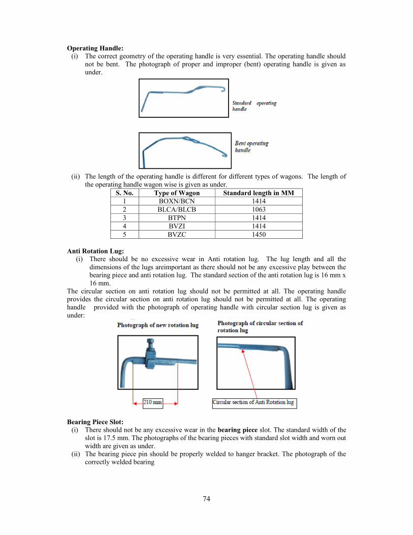
74
Operating Handle:
(i) The correct geometry of the operating handle is very essential. The operating handle should not be bent. The photograph of proper and improper (bent) operating handle is given as under.
(ii) The length of the operating handle is different for different types of wagons. The length of
the operating handle wagon wise is given as under. S. No. Type of Wagon Standard length in MM
1 BOXN/BCN 1414 2 BLCA/BLCB 1063 3 BTPN 1414 4 BVZI 1414 5 BVZC 1450
Anti Rotation Lug:
(i) There should be no excessive wear in Anti rotation lug. The lug length and all the dimensions of the lugs areimportant as there should not be any excessive play between the bearing piece and anti rotation lug. The standard section of the anti rotation lug is 16 mm x 16 mm.
The circular section on anti rotation lug should not be permitted at all. The operating handle provides the circular section on anti rotation lug should not be permitted at all. The operating handle provided with the photograph of operating handle with circular section lug is given as under:
Bearing Piece Slot:
(i) There should not be any excessive wear in the bearing piece slot. The standard width of the slot is 17.5 mm. The photographs of the bearing pieces with standard slot width and worn out width are given as under.
(ii) The bearing piece pin should be properly welded to hanger bracket. The photograph of the correctly welded bearing
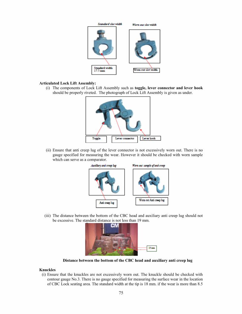
75
Articulated Lock Lift Assembly:
(i) The components of Lock Lift Assembly such as toggle, lever connector and lever hook should be properly riveted. The photograph of Lock Lift Assembly is given as under.
(ii) Ensure that anti creep lug of the lever connector is not excessively worn out. There is no gauge specified for measuring the wear. However it should be checked with worn sample which can serve as a comparator.
(iii) The distance between the bottom of the CBC head and auxiliary anti creep lug should not be excessive. The standard distance is not less than 19 mm.
Distance between the bottom of the CBC head and auxiliary anti creep lug
Knuckles
(i) Ensure that the knuckles are not excessively worn out. The knuckle should be checked with contour gauge No.3. There is no gauge specified for measuring the surface wear in the location of CBC Lock seating area. The standard width at the tip is 18 mm. if the wear is more than 8.5
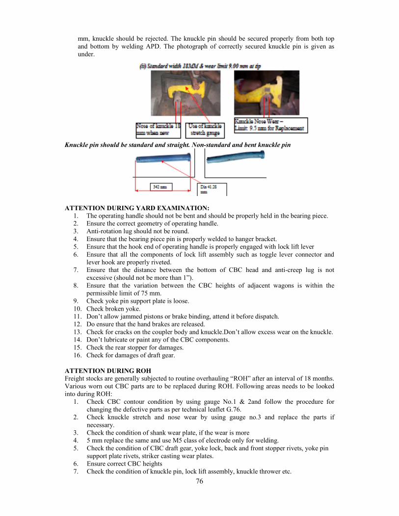
76
mm, knuckle should be rejected. The knuckle pin should be secured properly from both top and bottom by welding APD. The photograph of correctly secured knuckle pin is given as under.
Knuckle pin should be standard and straight. Non-standard and bent knuckle pin
ATTENTION DURING YARD EXAMINATION:
1. The operating handle should not be bent and should be properly held in the bearing piece. 2. Ensure the correct geometry of operating handle. 3. Anti-rotation lug should not be round. 4. Ensure that the bearing piece pin is properly welded to hanger bracket. 5. Ensure that the hook end of operating handle is properly engaged with lock lift lever 6. Ensure that all the components of lock lift assembly such as toggle lever connector and
lever hook are properly riveted. 7. Ensure that the distance between the bottom of CBC head and anti-creep lug is not
excessive (should not be more than 1”). 8. Ensure that the variation between the CBC heights of adjacent wagons is within the
permissible limit of 75 mm. 9. Check yoke pin support plate is loose. 10. Check broken yoke. 11. Don’t allow jammed pistons or brake binding, attend it before dispatch. 12. Do ensure that the hand brakes are released. 13. Check for cracks on the coupler body and knuckle.Don’t allow excess wear on the knuckle. 14. Don’t lubricate or paint any of the CBC components. 15. Check the rear stopper for damages. 16. Check for damages of draft gear.
ATTENTION DURING ROH Freight stocks are generally subjected to routine overhauling “ROH” after an interval of 18 months. Various worn out CBC parts are to be replaced during ROH. Following areas needs to be looked into during ROH:
1. Check CBC contour condition by using gauge No.1 & 2and follow the procedure for changing the defective parts as per technical leaflet G.76.
2. Check knuckle stretch and nose wear by using gauge no.3 and replace the parts if necessary.
3. Check the condition of shank wear plate, if the wear is more 4. 5 mm replace the same and use M5 class of electrode only for welding. 5. Check the condition of CBC draft gear, yoke lock, back and front stopper rivets, yoke pin
support plate rivets, striker casting wear plates. 6. Ensure correct CBC heights 7. Check the condition of knuckle pin, lock lift assembly, knuckle thrower etc.
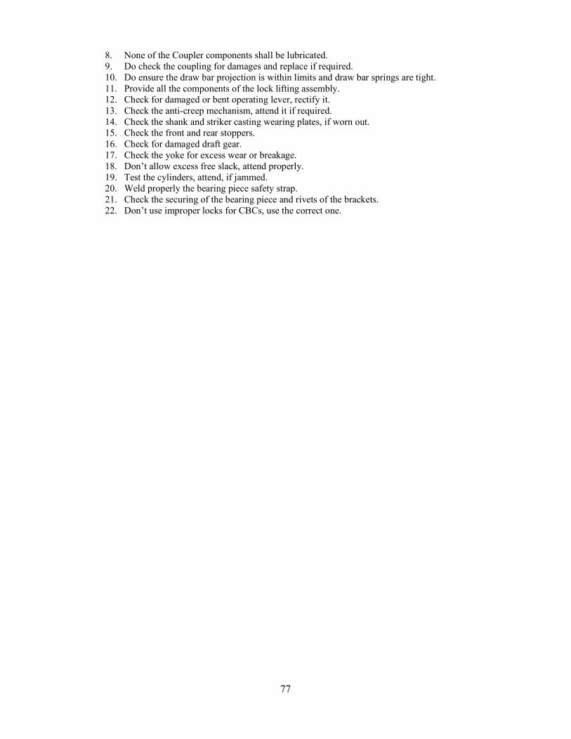
77
8. None of the Coupler components shall be lubricated. 9. Do check the coupling for damages and replace if required. 10. Do ensure the draw bar projection is within limits and draw bar springs are tight. 11. Provide all the components of the lock lifting assembly. 12. Check for damaged or bent operating lever, rectify it. 13. Check the anti-creep mechanism, attend it if required. 14. Check the shank and striker casting wearing plates, if worn out. 15. Check the front and rear stoppers. 16. Check for damaged draft gear. 17. Check the yoke for excess wear or breakage. 18. Don’t allow excess free slack, attend properly. 19. Test the cylinders, attend, if jammed. 20. Weld properly the bearing piece safety strap. 21. Check the securing of the bearing piece and rivets of the brackets. 22. Don’t use improper locks for CBCs, use the correct one.
78
ACCIDENT RELIEF TRAIN (ART) Vide Railway Boards letter no. 99/M/(M&P)/7/6 dated 24.09.1999, the stress was laid down in restricting the length of ARTs to avoid delays in movement to site and problem in placement of crane/Tool vans etc. In “A” and “B” class ART, total number of coaches were proposed as 6 numbers only. In “A” class ART, by including crane as 1st and 2nd vehicle, the total number of vehicles were proposed not be more than 8. But in the present scenario, there was a need to review the old composition consequent upon introduction of HLC recommendations & present requirement of space for storing tools and equipments. The revised composition will be as under –
1. In “A” class ART Total number of coaches will be 5+3 wagons with 140 T Crane.
1st vehicle will be 140 Te. Capacity diesel/steam break down crane with Match Truck 2nd vehicle will be RT/BCN HS (Crane packing Van and heavy tools, wire ropes & OHE
material 3rd vehicle will be Crane Staff and Kitchen Van. 4th vehicle will be BRN HS (containing Rails and Crossings). 5th vehicle will be BCN HS (complete Engineering Material and OHE items) 6th vehicle will be Tool and Equipment Van (All critical mechanical tools, office and Fire
fighting section. Provision of guard seat with guard van valve) 7th vehicle will be C&W, Elect. And Telecom. Van (Material of Telecom, Elect. & C&W) 8th vehicle will be Re-railing Equipment Van (MFD/LUKAS equipments and its material) 9th vehicle will be Staff and Kitchen Van(MFD/LUKAS staff and Kitchen)
1. In “B” class ART total number of vehicles would be 6 since ART would be without Break Down crane and Match Truck. The composition would be same as above.
2. More often that not only LUKAS/MFD is ordered without Break down crane, Break down
crane too ordered without Lucas/MFD. If only LUKAS/MFD is ordered then the Break down formation would be as under:
1st vehicle will be BRN HS (containing Rails and Crossings). 2nd vehicle will be BCN HS (complete Engineering Material and OHE items) 3rd vehicle will be Tool and Equipment Van (All critical mechanical tools, office and Fire
fighting section. Provision of guard seat with guard van valve) 4th vehicle will be C&W, Elect. And Telecom. Van (Material of Telecom, Elect. & C&W) 5th vehicle will be Re-railing Equipment Van (MFD/LUKAS equipments and its material) 6th vehicle will be Staff and Kitchen Van(MFD/LUKAS staff and Kitchen)
3. If only Break down Crane is ordered then the formation of Break down train would
be as under:
1st vehicle will be 140 Te. Capacity diesel/steam break down crane with Match Truck
2nd vehicle will be RT/BCN HS (Crane packing Van and heavy tools, wire ropes. 3rd vehicle will be Crane Staff and Kitchen Van. Note: Seating arrangement for staff will be available in both formations according to the staff requirement. Organizational issues, such as yardsticks and selection criteria to provide suitable personnel. 1. The staff for deployment in Accident Relief Trains should be carefully chosen. They should be physically fit, must have stamina to do strenuous work for long extended hours. 2. Average age of unskilled persons working in ART/ARME/140 Te. Crane should not be more
79
than 50 years. The upper age limit for artisans should be 52 and of supervisors, it should be not more than 52 years. 3. ART staff inducted for Breakdown duties must be qualified. They must possess a certificate in any course from ITI. 4. Staff deployment for Accident Relief Train should be as under:
- All nominated staff attached to break down should be deployed at accident site. - Only core staff will be permanently deployed for the maintenance of break down crane and ART equipment. - But the staff other than maintenance gangs when not required for break down duties shall carry on their normal work at ROH, IOH, Diesel Trip Shed etc.
5. In “A” class ART total 44+14=58 staff nominated should be deployed at accident site to facilitate simultaneous operation of crane and HRE. Total staff in “A” class ART for crane operation should be 35 and staff in "A" class ART for LUKAS/MFD operation should be 23. 6. Only core staff required for maintenance of break down crane and ART equipment would remain with ART permanently attached to carry out daily checks, schedules, maintenance of re-railing equipement, examination of wire ropes, general upkeep of tools and equipments. 7. Only 13 staff for the purpose of maintenance of breakdown and ART equipment in “A” class ART has been identified. When not required for break down duties, then other 31 staff out of Total 44 would carry on their normal work at ROH, IOH, Diesel Trip Shed and Diesel Sheds etc. 8. Only 9 staff for the purpose of maintenance of ART equipment in "B" Class ART has been identified. When not required for Break Down duties, then other 14 staff out of total 23 would carry on their normal work at ROH, IOH, Diesel Trip Shed and Diesel Sheds etc. 9. Training should be imparted to ART staff at induction stage followed by refresher course at an interval of five years. The training and the course should cover following areas.
- Knowledge of HRD, HRE and other equipment both in operation and maintenance. - Safety practice to be observed at accident site - General management at accident site such as fixing of luminous Barrier tape to ward off inquisitive unauthorized persons, and matters of other general discipline. - How to work in close coordination with other supporting agencies such as fire brigade, police and local voluntary organization etc. at the time of Railway accident.
10. Training of staff deployed in ART & for Break Down Crane Operation: Crane operators and crane assistants should be imparted training at induction stage followed by refresher course at an interval of 3 years. The training and the course should cover following areas:
- Knowledge of breakdown crane, its lifting capacity and preparation of crane. - Crane safety such as propping of crane on level and super elevated track. Safety to be observed in slewing, derricking operation and traveling - Knowledge about the defects on crane and daily checks to be carried out - Knowledge of crane schedules - Knowledge of wire rope slings and chains and their periodical examination. - Knowledge of emergency operation of crane in the event of failure of Main Engine at accident site.
TURNING OUT OF ARTS/ARMVS: (i) Target time for turning out the Medical Van:-
In case of double exit siding - 15 Minutes (20 minutes given in S.Rly) In case of single exit sidings - 20 Minutes (25 minutes given in S.Rly)
The time is reckoned from the time of ordering to the time of despatch. Note: Instructions given in Accident manual of zonal railway should be followed for target time for turning out ARME/ARMV. (ii) Target time for turning out the Break down trains:-
During Day – 30 Minutes During Night – 45 minutes
The time is reckoned from the time of ordering to the time of leaving the shed. (iii) An accident relief train when proceeding to the site of accident will have precedence over all other trains. A break down train/Tower wagon must not be detained for Guard, and must leave with the In-charge of Breakdown train. A Guard must be quickly arranged later. (iv) ARMVs would also be given priorities in the return journey also as they may be required at
80
other locations too. SELECTION OF ART/ARME STAFF: The following criteria is given for the selection of staff to work on ART/SPART/ARME/140Te. Crane gang:
1. Physical Fitness: He should be physically fit and capable of doing hard work. He should be strong and possess excellent stamina to do long hours of work without getting fatigued.
2. Accident Proneness: An accident prone person is not only a menace to himself but it also a potential danger to the lives of his colleagues. It is therefore necessary to examine the service records as well as the actual habits to check how careful a person is in his work and how safe his working habits are.
3. Reaction time: Since the relief work needs quick response to orders as well as the fast changing situations to avoid personal injuries or injuries to others and for quickness of work, it is essential that the person has excellent reaction time for quick response to situation and is always alert.
4. Skill of Artisans: The Artisans selected for the gang must be dexterous and possess more than average skill. They must show aptitude in their own field or work.
5. Team Sprit: The entire relief operations depend on team work, mutual trust and close co-operation and coordination amongst the members. The individualist or egoist person should be kept out of this gang.
6. Intelligence and resourcefulness: The situations at the site of accident are varied and require lot of resourcefulness and ingenuity in.
7. Sincerity, willingness and obedience: The persons must show his willingness to work on this job of relief operations and must be sincere in his duties. He must be obedient so as to avoid friction, etc.
8. Attendance: Only those regular in attendance should be taken on this gang so that every time there is a call, they invariably report on duty. Even after nomination, if a person is found absconding, he should be removed from the gang immediately.
9. Leadership: A few persons should be those who show leadership qualities who can act as guide and group leaders of the available staff.
10. Railway Quarters: a) Adequate no. of Quarters for the entire gang should be ear-marked as ART quarters. b) Quarters for ART/SPART/ARME/Crane Staff must be as close as possible to the ART
stabling siding. c) Only Standard type Railway Quarters should be earmarked for ART/SPART/ARME
gangs, which should be maintained well. d) Whenever new quarters are planned for constructions by the divisions, requirement for
the ART/SPART/ARME should be taken care of on priority. ART STAFF TRAINING:
1. Every person nominated on Relief train gang is given intensive training in all types of works which he may be called upon to do at accident sites.
2. The training should be such as top make him proficient in dealing with every type of situations met with during relief and rescue operations. Such staff will be able to quickly decide the best course of action to restore traffic with minimum damage, to the rolling stock.
3. The training will enable them to deal with the injured passengers/staff promptly thereby improving the chances of saving their lives and reducing extent of injuries.
4. Expenditure on such training will yield adequate returns in the form of faster and safer normalization of through traffic.
5. ART staff should be given all round training with a compulsory foundation course and refresher course (once in 3 years). Physical fitness and developing a team spirit is equally important in the training scheme.
6. Foundation course should be part of initial training for Mechanical supervisors. Supervisors of other departments should also be given special training. Mechanical and Electrical probationary officers should be trained in this aspect during their initial training.
81
7. Running/Operating, TTE/CTI/ Conductor staff should also be given intensive training to deal with the accident and in firs aid.
SOUNDING OF ACCIDENT ALARM HOOTERS Electric Alarm Siren/Steam Hooters are provided in the loco shed at stations where accident relief train /Medical Van are stabled. The Siren /Hooter must be sounded immediately after notice of accident is received requiring the Medical Van/Break Down Train. Following Codes are prescribed for sounding alarm Siren/Hooter.
S. No. BLASTS DESCRIPTION 01 02 long Blasts each of 45 seconds
duration with 05 seconds break. For Accident in Loco/Yard at Home station requiring Break Down Train only.
02 03 long Blasts each of 45 seconds duration with 05 seconds break.
For Accidents out side Home station requiring Break Down Train only.
03 04 long Blasts each of 45 seconds duration with 05 seconds break.
For Accidents at Home station requiring Medical and Break Down Train.
04 05 long Blasts each of 45 seconds duration with 05 seconds break.
For Accidents out side Home station requiring Medical Van and Break Down Train.
05 01 long Blast of 90 seconds duration. For cancellation of Medical Van/Break Down Train.
Note: - The Alarm Signal shall be repeated twice with an interval of 05 minutes between each code signal. List of Tools and equipment in “A” & “B” class ART- Generator and electrical equipment Aska lights Illumination Self-contained breathing apparatus Oxy cutting equipment Inflatable lifting air bags Compressor pneumatic tools Life Jackets Hydraulic re-railing equipments V Sat equipment Jacks Satellite phone Wire ropes, slings and shackles. Plasma cutting equipment Chains slings and wooden packing Oxy fuel cutting equipment Other mechanical equipments Fitters tools Records Camera and video recorder
82
ART/MFD/SPART/140T CRANE MAINTENANCE The following points may be kept in mind by the Divisions for Accident Management:-
1. For accidents involving Passenger trains, the BD cranes and MFDs in either direction in the vicinity of the site must immediately be ordered by the Control as a routine.
2. In case of Goods train accidents involving mainline, the following procedure should be followed:- Movement of 140 Te BD cranes must have the approval of CMPE/Hqrs who is overall
incharge of the management of ARTs, and in his absence any Mechanical Officer in Headquarters. In rare cases, where both lines are affected and when delays in contacting Headquarters are envisaged, cranes may be ordered by Division, but this should only be an exception.
Movement of MFDs can be ordered by the Divisional Mechanical officers as desired by DRMs.
3. In case of accidents in Yard not affecting through movement, the derailment may be tackled using ramps to the extent possible and MFD/Crane ordered only if the derailment CANNOT be tackled by Jacks (HRE). This decision may be taken by the Divisional officers at their discretion depending upon the information available from site.
4. ARTs should be turned out within the target time of 30 minutes by day and 45 minutes during night. ARMV should be turned out within 20 minutes from double entry siding and 25 minutes from single entry siding during both day and night (zonal railways may decide target time).
5. Movement of ARTs to the accident spots should be given top priority and should not be stopped enroute. It is the responsibility of the Controlling DRM and his Officers that no slackness is allowed in this regard.
6. ARTs should be moved to the base Depot as soon as the restoration work is over. 7. For a minor derailment involving a few wagons, as far as possible MFDs should only be
deployed leaving the crane at the base station in readiness to attend major accidents. 8. Wherever road approach is available, attempt should be made to take the MFD equipment
by road through lorry and for this purpose, departmental lorry should be earmarked. Wherever department lorries are not available to move the MFD/HRE, private lorries may be invariably hired.
9. Wherever MFD/HRE is required to serve both BG and MG territory, arrangement for moving MFD/HRE by lorry is a must.
10. Mock trials of ART should be done earnestly as prescribed to test the efficacy and correct any deficiency in the system.
11. Whenever assistance of additional BD crane/MFD is required from neighbouring division or adjacent Railways. CMPE or any other HOD of the Mechanical Department will do the necessary liaison.
MAINTENANCE OF RELIEF TRAINS:
1. Loco Running Shed Foremen or others in charge of relief-van and relief trains are responsible for seeing that they are always fully equipped and in running order, and that the relief-van contains the medical chest.
2. Sr. DSTE is responsible for seeing that the control telephone and phonophore equipments or portable emergency telephones where provided for use in the electrified sections are complete and in good working order. He must personally inspect and test this equipment quarterly.
3. Medical Officer-in-charge is responsible for seeing that the prescribed stock of medicines and surgical appliances is maintained in the chests and almirahs and that the instruments and medical appliances are in perfect working order. He must personally inspect this equipment quarterly.
83
4. Sr. DEN (Co-ordination) must ensure that the permanent way tools and stores of suitable pattern are complete and in good condition. He must personally inspect these equipments quarterly.
5. Sr. DEE (TRD) must ensure that the equipment in the electric traction bogies of the relief trains provided for use in the electrified sections is of suitable pattern, complete and in good condition for use on traction distribution system. He must personally inspect the equipments quarterly.
6. Sr. Divisional Mechanical Engineer is responsible for the complete relief train as a unit. He must satisfy himself that deficiencies are made good after use every time by all the departments concerned. He must ensure that the relief train staff is conversant with the use of all the equipments provided in the train. He must personally inspect the train and its equipments quarterly.
MAINTENANCE AND REPAIRS OF CRANES I. OVERHAULS: The date of each examination of 140 T. Diesel hydraulic crane break down crane should be painted plainly on the crane at marked location.
The 140 T. Diesel Hydraulic Cranes of ARTs will fall due for its periodical overhaul every 08 years. Cranes will however be examined by the division as per the schedules prescribed by RDSO circulated by ministry of Railways incorporating the schedules prescribed by Central Railway Locomotive Workshop Parel for Cowans Sheldon, UK 140 T. Cranes and prescribed by Jamalpur Workshop for Gottwald 140 T. cranes of Germany. The POH of Cowans Boyed/Cowans Sheldon UK will be undertaken by Parel Workshop and the POH of Gottwald Germany will be undertaken by Jamalpur Workshop. Divisional Railway Manager (Optg.)/(Mech.) will recommend cranes under their control for overhaul to the Chief Operating Manager/Chief Mechanical Engineer through their Divisional Mechanical authority who will arrange programme for releasing cranes for acceptance for overhaul in Workshop in consultation with Chief Workshop Manager, Parel/Jamalpur. The breakdown cranes i.e. 140T Diesel crane under the control of Divisional Railway Manager (Mechanical) will recommend these cranes for over haul in Parel /JMP Workshop with consultation of CWM/Parel/JMP. II. HEAVY REPAIRS: If a crane requires heavy repairs, which cannot be executed by Running Sheds, the Divisional Railway Manager (Mechanical) will represent the case to the Chief Mechanical Engineer, who will arrange for the crane to be relieved for heavy repairs in Parel Workshop/JMP Workshop. III. RUNNING REPAIRS AND MAINTENANCE OF CRANES: Divisional Railway Manager (Operating)/(Mech.) will be responsible for running repairs and ordinary maintenance of cranes. Breakdown Cranes are the direct responsibility of the Incharge ART of the Depots where these cranes are stabled, and they will be responsible for maintenance of the cranes in efficient condition and for the periodical examinations for their safe working.
Other travelling Cranes will be maintained by SSE/Millwright organization nominated to do so by their Divisional Railway Manager (Mechanical). Shed/Mill Wright staff organized by the division will inspect monthly and carry out minor repairs such as reduction of brass bearings, taking up slack on keys, examination of piston rings, valves, under gears etc., and check up all gear wheels for broken teeth or partially broken teeth and pinning them to avoid further damage and also clean clutch cones and rebearing where necessary.
All non-breakdown cranes will be maintained by respective owning department in accordance with the provision laid down. All 140 T. Diesel hydraulic cranes of ARTs will be maintained by the SSE(Diesel) nominated to do so by their Sr DME/DME diesel Sheds where these cranes are stabled and where there is only trip sheds are available, Sr DME of the division will nominate the supervisor for maintenance of the crane stabled at their depot. The maintenance of these cranes will be carried out in accordance with
84
the schedules prescribed by RDSO. The day to day maintenance of match truck and ballast wagon of 140 T. Diesel hydraulic
break down cranes will be carried out by the SSE(C&W) of carriage and Wagon department where these cranes are stabled.
Hand Cranes will be maintained in good repair by SSE(C&W). Divisional Railway Managers (Mechanical) will nominate the cranes to be maintained by each SSE(C&W) of carriage and Wagon department. Periodical Examinations of Hand Cranes will be carried out by Carriage Inspectors at Depots, where no SSE(C&W) is posted.
In case of cranes running with roller bearing axle boxes, all the axle boxes must be examined for condition of their grease and the topping of these boxes with fresh grease must be done after every six months. NOTE: In addition to the above, the Ultrasonic flaw detector testing of the crane axle boxes including match truck and relieving trucks must be carried out after every 12 months and the result of testing should be recorded in the register. Date of such testing also to be marked at the places as indicated above. PERIODICAL EXAMINATION OF CRANES:
1. 140 Te. Diesel hydraulic cranes of ART‟s will be examined at intervals regularly as prescribed by RDSO.
2. The Break down incharge / SSE nominated to do so are responsible for the periodical examination of 140 Te. Break down cranes.
3. To ensure proper upkeep and reliability in safe working of 140 Te. Crane at site, the following periodicity of schedules has been prescribed by RDSO.
For Cowans Sheldon (old), Cowans sheldon (New) and Gottwald (old crane)
S.No. Duration Working hours Set of schedule form 1. Daily Form A 2. Monthly 100 Form B 3. 3 Monthly 250 Form C 4. 6 Monthly 500 Form D 5. Yearly 1000 Form E 6. 2 Yearly 2000 Form F 7. 4 Yearly 4000 Form G 8. 8 Yearly 8000 POH
For Gottwald (New Crane) CIL Main Engine NTA 855 L
S.No. Duration Working hours Set of schedule form
1. Daily Form A 2. Monthly 125 Form B 3. 6 Monthly 250 Form D 4. Yearly 1500 Form E 5. 2 Yearly 6000 Form F 6. 3 Yearly 6000 Form G 7. 8 Yearly POH
* Whichever is earlier. 4. Particular of periodical examinations should be maintained on a register. 5. Any repair to be executed should be reported to the subordinate incharge of the
maintenance of the crane. 6. Record of such examinations entered in the register will be signed by the maintenance
supervisor. 7. Particulars of periodical examinations of 140T. Crane will be recorded in the prescribed
schedule forms as laid down by the RDSO.
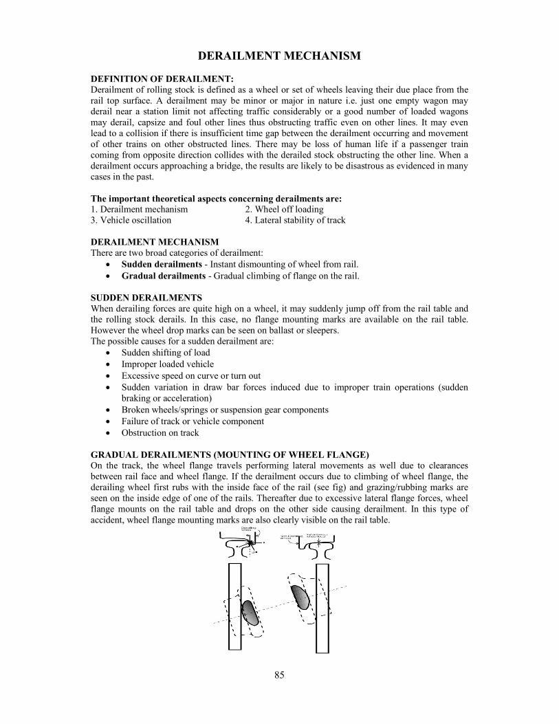
85
DERAILMENT MECHANISM DEFINITION OF DERAILMENT: Derailment of rolling stock is defined as a wheel or set of wheels leaving their due place from the rail top surface. A derailment may be minor or major in nature i.e. just one empty wagon may derail near a station limit not affecting traffic considerably or a good number of loaded wagons may derail, capsize and foul other lines thus obstructing traffic even on other lines. It may even lead to a collision if there is insufficient time gap between the derailment occurring and movement of other trains on other obstructed lines. There may be loss of human life if a passenger train coming from opposite direction collides with the derailed stock obstructing the other line. When a derailment occurs approaching a bridge, the results are likely to be disastrous as evidenced in many cases in the past. The important theoretical aspects concerning derailments are: 1. Derailment mechanism 2. Wheel off loading 3. Vehicle oscillation 4. Lateral stability of track DERAILMENT MECHANISM There are two broad categories of derailment:
Sudden derailments - Instant dismounting of wheel from rail. Gradual derailments - Gradual climbing of flange on the rail.
SUDDEN DERAILMENTS When derailing forces are quite high on a wheel, it may suddenly jump off from the rail table and the rolling stock derails. In this case, no flange mounting marks are available on the rail table. However the wheel drop marks can be seen on ballast or sleepers. The possible causes for a sudden derailment are:
Sudden shifting of load Improper loaded vehicle Excessive speed on curve or turn out Sudden variation in draw bar forces induced due to improper train operations (sudden
braking or acceleration) Broken wheels/springs or suspension gear components Failure of track or vehicle component Obstruction on track
GRADUAL DERAILMENTS (MOUNTING OF WHEEL FLANGE) On the track, the wheel flange travels performing lateral movements as well due to clearances between rail face and wheel flange. If the derailment occurs due to climbing of wheel flange, the derailing wheel first rubs with the inside face of the rail (see fig) and grazing/rubbing marks are seen on the inside edge of one of the rails. Thereafter due to excessive lateral flange forces, wheel flange mounts on the rail table and drops on the other side causing derailment. In this type of accident, wheel flange mounting marks are also clearly visible on the rail table.
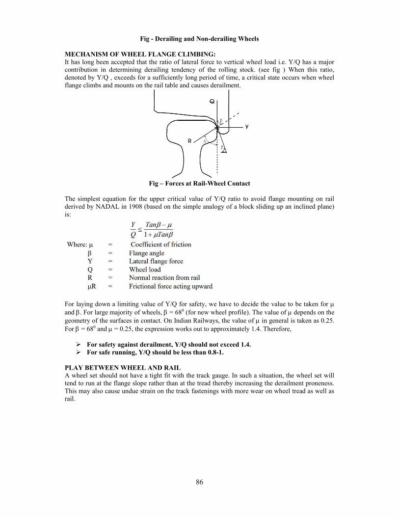
86
Fig - Derailing and Non-derailing Wheels MECHANISM OF WHEEL FLANGE CLIMBING: It has long been accepted that the ratio of lateral force to vertical wheel load i.e. Y/Q has a major contribution in determining derailing tendency of the rolling stock. (see fig ) When this ratio, denoted by Y/Q , exceeds for a sufficiently long period of time, a critical state occurs when wheel flange climbs and mounts on the rail table and causes derailment.
Fig – Forces at Rail-Wheel Contact
The simplest equation for the upper critical value of Y/Q ratio to avoid flange mounting on rail derived by NADAL in 1908 (based on the simple analogy of a block sliding up an inclined plane) is:
For laying down a limiting value of Y/Q for safety, we have to decide the value to be taken for and . For large majority of wheels, = 680 (for new wheel profile). The value of depends on the geometry of the surfaces in contact. On Indian Railways, the value of in general is taken as 0.25. For = 680 and = 0.25, the expression works out to approximately 1.4. Therefore,
For safety against derailment, Y/Q should not exceed 1.4. For safe running, Y/Q should be less than 0.8-1.
PLAY BETWEEN WHEEL AND RAIL A wheel set should not have a tight fit with the track gauge. In such a situation, the wheel set will tend to run at the flange slope rather than at the tread thereby increasing the derailment proneness. This may also cause undue strain on the track fastenings with more wear on wheel tread as well as rail.
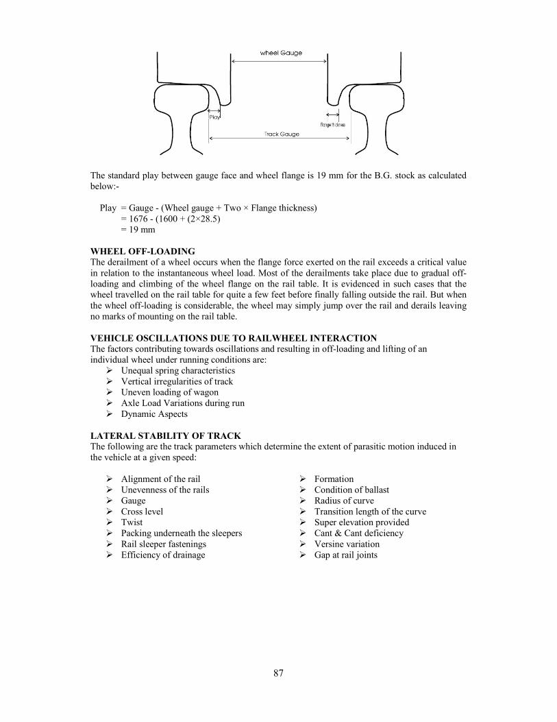
87
The standard play between gauge face and wheel flange is 19 mm for the B.G. stock as calculated below:- Play = Gauge - (Wheel gauge + Two × Flange thickness)
= 1676 - (1600 + (2×28.5) = 19 mm
WHEEL OFF-LOADING The derailment of a wheel occurs when the flange force exerted on the rail exceeds a critical value in relation to the instantaneous wheel load. Most of the derailments take place due to gradual off-loading and climbing of the wheel flange on the rail table. It is evidenced in such cases that the wheel travelled on the rail table for quite a few feet before finally falling outside the rail. But when the wheel off-loading is considerable, the wheel may simply jump over the rail and derails leaving no marks of mounting on the rail table. VEHICLE OSCILLATIONS DUE TO RAILWHEEL INTERACTION The factors contributing towards oscillations and resulting in off-loading and lifting of an individual wheel under running conditions are:
Unequal spring characteristics Vertical irregularities of track Uneven loading of wagon Axle Load Variations during run Dynamic Aspects
LATERAL STABILITY OF TRACK The following are the track parameters which determine the extent of parasitic motion induced in the vehicle at a given speed:
Alignment of the rail Unevenness of the rails Gauge Cross level Twist Packing underneath the sleepers Rail sleeper fastenings Efficiency of drainage
Formation Condition of ballast Radius of curve Transition length of the curve Super elevation provided Cant & Cant deficiency Versine variation Gap at rail joints
88
ACCIDENT INVESTIGATION AND CRS INQUIRY ACCIDENT: For the purpose of Railway working, accident is an occurrence in the course of working of Railway, which does or may affect -
Safety of the Railway, its Engine, Rolling Stock, Permanent Way and Works, Fixed Installations, Passengers or Servants or which affects Safety of others Delay to train or loss to the Railway.
For statistical purposes, accidents have been classified in categories from ‘A’ to ‘R’ excluding ‘I’ and ‘O’. SERIOUS ACCIDENT: Accident to a train carrying passengers which is attended with -
Loss of life or with grievous hurt to a passenger or passengers in the train. Serious damage to railway property of the value exceeding Rs.2,00,00,000. Any other accident which requires the holding of an inquiry by the Commissioner of
Railway Safety shall also be deemed to be a serious accident. However, the following shall be excluded:- (a) Cases of trespassers run over and injured or killed through their own carelessness or of passengers injured or killed through their own carelessness; (b) Cases involving persons being Railway servant or holding valid passes/ tickets or otherwise who are killed or grievously injured while travelling outside the rolling stock of a passenger train such as on foot board or roof or buffer but excluding the inside of vestibules between coaches or run over at a Level Crossing or elsewhere on the Railway track by a train; and (c) Level Crossing accident where no passenger or Railway Servant is killed or grievously hurt unless the Chief Commissioner of Railway Safety or Commissioner of Railway Safety is of the opinion that the accident requires the holding of an inquiry by the Commissioner of Railway Safety. DISASTER: A Disaster is an occurrence which may include a train accident whose consequences are so adverse or whose magnitude is so large that it cannot be handled by a single Railway Division, and the resources of the entire Zonal Railway and other agencies are required to be mobilized. Chief Operations Manager is the Authorized Officer who will declare an occurrence as a disaster after getting the General Manager’s approval. OBJECTIVES IN DEALING WITH ACCIDENTS: (a) To save life and alleviate suffering. (b) To protect property. (c) To provide succour and help to affected passengers. (d) To ascertain the cause of an accident. CLASSIFICATION OF ACCIDENT: Accidents are classified under following heads: 1. Train Accidents: A Train accident is an accident that involves a train. Train accidents are further divided as -
(A) Consequential train accidents: It includes train accidents having serious repercussion in terms of loss of human life, human injury, loss to Railway property or interruption to Rail traffic. Train accidents under following classification will be termed as consequential train accidents: -
Collision: All cases under categories A-1 to A-4 Fire: All cases under categories B-1 to B-4 Level Crossing: All cases under categories C-1 to C-4 Derailment: All cases under categories D-1 to D-4
89
Miscellaneous: All cases under categories E-1
(B) Other train accidents: All other accidents which are not covered under the definition of consequential train accidents are to be treated as ‘Other train accidents’. These include accidents under categories B-5, B-6, C-5 to C-8, D-5 and E-2.
2. Yard Accidents: All accidents that take place in a yard and do not involve a train are termed as Yard Accidents. These include accidents falling under categories A-5, B-7, C- 9 and D-6. 3. Indicative Accidents: In real term, they are not accidents but are serious potential hazards and include all cases of train passing signal at danger, averted collision, breach of block rule coming under classification F, G and H. 4. Equipment failures: These include all failures of railway equipments i.e. failure of locomotives, rolling stock, permanent way, overhead wire, signalling and telecommunication equipments and include cases falling under classification J, K, L and M. 5. Unusual Incidents: These include cases related to law and order but not resulting in train accidents and other incidents under classification N, P, Q and R.
SITE INVESTIGATION Unless reasons for derailment are obvious from the initial inspection at site, comprehensive investigation in a logical sequence is needed to ascertain the actual cause of derailment. The site investigation is primarily concerned with identification of evidence and related data before restoring the track and vehicles. The main purposes are to:
Locate the initial point of derailment. To identify the first derailed vehicle and wheel. To obtain sufficient evidence to determine the course of events up to the time derailed train
came to a halt. To explain why the vehicle derailed initially at that particular point on the track.
The site investigation should be carried out in the following sequence:
1. First considerations 2. Site sketch 3. Flange marks 4. Operational Defects/Failures 5. Track survey and examination 6. Vehicle examination
1. First Consideration: The sequence of events to be recorded i.e. how derailment occurred prima facie, from the beginning to the time the train came to a halt. The position of vehicles after derailment must be recorded. The wheel marks at the initial point of derailment are to be examined in order to establish the category of derailment i.e. sudden or gradual. 2. Site Sketch: A sketch of the whole site showing the position of derailed vehicles relative to both rails as well as other evidences if any together with the track damages must be prepared. If this is not done, serious difficulties will be encountered later when this evidence is required for correlating the events relating to vehicle and track interaction. 3. Flange marks on Rail: The most important thing in investigating the derailments is to locate and examine the wheel mounting marks or the marks at the initial point of derailment in order to determine whether the derailment was sudden or gradual. A careful analysis is required to be done on wheel mounting marks found on the rail table (Fig. 2.1). If it is difficult to ascertain the first vehicle which derailed, it is necessary to detail the damage
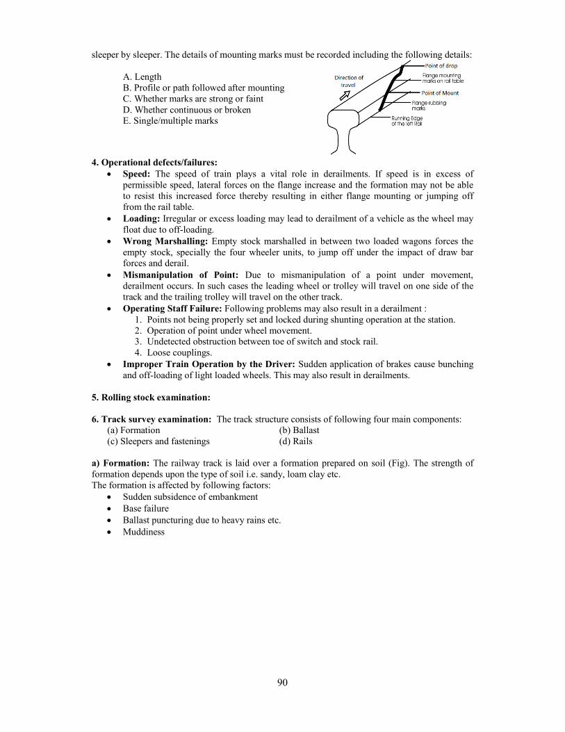
90
sleeper by sleeper. The details of mounting marks must be recorded including the following details: A. Length B. Profile or path followed after mounting C. Whether marks are strong or faint D. Whether continuous or broken E. Single/multiple marks
4. Operational defects/failures:
Speed: The speed of train plays a vital role in derailments. If speed is in excess of permissible speed, lateral forces on the flange increase and the formation may not be able to resist this increased force thereby resulting in either flange mounting or jumping off from the rail table.
Loading: Irregular or excess loading may lead to derailment of a vehicle as the wheel may float due to off-loading.
Wrong Marshalling: Empty stock marshalled in between two loaded wagons forces the empty stock, specially the four wheeler units, to jump off under the impact of draw bar forces and derail.
Mismanipulation of Point: Due to mismanipulation of a point under movement, derailment occurs. In such cases the leading wheel or trolley will travel on one side of the track and the trailing trolley will travel on the other track.
Operating Staff Failure: Following problems may also result in a derailment : 1. Points not being properly set and locked during shunting operation at the station. 2. Operation of point under wheel movement. 3. Undetected obstruction between toe of switch and stock rail. 4. Loose couplings.
Improper Train Operation by the Driver: Sudden application of brakes cause bunching and off-loading of light loaded wheels. This may also result in derailments.
5. Rolling stock examination: 6. Track survey examination: The track structure consists of following four main components:
(a) Formation (b) Ballast (c) Sleepers and fastenings (d) Rails
a) Formation: The railway track is laid over a formation prepared on soil (Fig). The strength of formation depends upon the type of soil i.e. sandy, loam clay etc. The formation is affected by following factors:
Sudden subsidence of embankment Base failure Ballast puncturing due to heavy rains etc. Muddiness
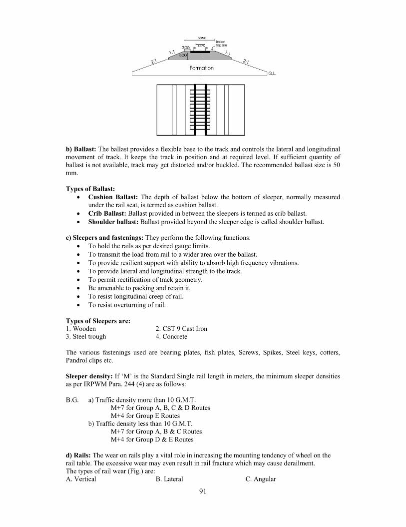
91
b) Ballast: The ballast provides a flexible base to the track and controls the lateral and longitudinal movement of track. It keeps the track in position and at required level. If sufficient quantity of ballast is not available, track may get distorted and/or buckled. The recommended ballast size is 50 mm. Types of Ballast:
Cushion Ballast: The depth of ballast below the bottom of sleeper, normally measured under the rail seat, is termed as cushion ballast.
Crib Ballast: Ballast provided in between the sleepers is termed as crib ballast. Shoulder ballast: Ballast provided beyond the sleeper edge is called shoulder ballast.
c) Sleepers and fastenings: They perform the following functions:
To hold the rails as per desired gauge limits. To transmit the load from rail to a wider area over the ballast. To provide resilient support with ability to absorb high frequency vibrations. To provide lateral and longitudinal strength to the track. To permit rectification of track geometry. Be amenable to packing and retain it. To resist longitudinal creep of rail. To resist overturning of rail.
Types of Sleepers are: 1. Wooden 2. CST 9 Cast Iron 3. Steel trough 4. Concrete The various fastenings used are bearing plates, fish plates, Screws, Spikes, Steel keys, cotters, Pandrol clips etc. Sleeper density: If ‘M’ is the Standard Single rail length in meters, the minimum sleeper densities as per IRPWM Para. 244 (4) are as follows: B.G. a) Traffic density more than 10 G.M.T.
M+7 for Group A, B, C & D Routes M+4 for Group E Routes
b) Traffic density less than 10 G.M.T. M+7 for Group A, B & C Routes M+4 for Group D & E Routes
d) Rails: The wear on rails play a vital role in increasing the mounting tendency of wheel on the rail table. The excessive wear may even result in rail fracture which may cause derailment. The types of rail wear (Fig.) are: A. Vertical B. Lateral C. Angular
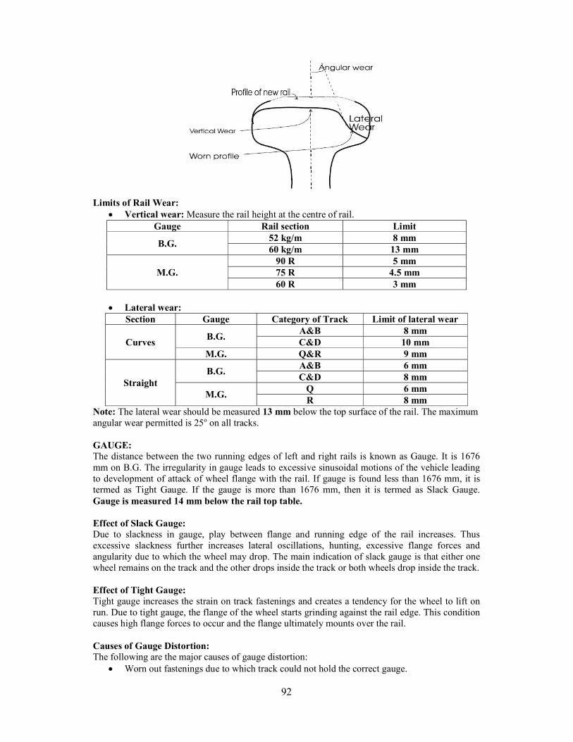
92
Limits of Rail Wear:
Vertical wear: Measure the rail height at the centre of rail. Gauge Rail section Limit
B.G. 52 kg/m 8 mm 60 kg/m 13 mm
M.G. 90 R 5 mm 75 R 4.5 mm 60 R 3 mm
Lateral wear:
Section Gauge Category of Track Limit of lateral wear
Curves B.G.
A&B 8 mm C&D 10 mm
M.G. Q&R 9 mm
Straight B.G.
A&B 6 mm C&D 8 mm
M.G. Q 6 mm R 8 mm
Note: The lateral wear should be measured 13 mm below the top surface of the rail. The maximum angular wear permitted is 25o on all tracks. GAUGE: The distance between the two running edges of left and right rails is known as Gauge. It is 1676 mm on B.G. The irregularity in gauge leads to excessive sinusoidal motions of the vehicle leading to development of attack of wheel flange with the rail. If gauge is found less than 1676 mm, it is termed as Tight Gauge. If the gauge is more than 1676 mm, then it is termed as Slack Gauge. Gauge is measured 14 mm below the rail top table. Effect of Slack Gauge: Due to slackness in gauge, play between flange and running edge of the rail increases. Thus excessive slackness further increases lateral oscillations, hunting, excessive flange forces and angularity due to which the wheel may drop. The main indication of slack gauge is that either one wheel remains on the track and the other drops inside the track or both wheels drop inside the track. Effect of Tight Gauge: Tight gauge increases the strain on track fastenings and creates a tendency for the wheel to lift on run. Due to tight gauge, the flange of the wheel starts grinding against the rail edge. This condition causes high flange forces to occur and the flange ultimately mounts over the rail. Causes of Gauge Distortion: The following are the major causes of gauge distortion:
Worn out fastenings due to which track could not hold the correct gauge.
93
Damaged sleepers and unserviceable sleepers due to which fastening become loose. Fastening not properly secured and becoming loose due to high speed vibrations. Missing fastenings i.e. keys, dogspikes etc.
Permissible Gauge tolerances:
Tight Slack On straight (All gauges) 3 mm 6 mm On curves with radius:
i) More than 400 m on B.G. 275 m on M.G. and
175m on N.G. 3 mm 15 mm
ii) Less than 400 m on B.G., 275 m on M.G. and
175 m on N.G. Nil 20 mm
CROSS LEVEL: The relative difference in the height of left and right rail at a given point on the track is known as Cross Level (on straight track). The fluctuating cross level differences in the track result in track Buckling and help in developing undesirable oscillations on vehicles adversely affecting their stable running. Due to variation in Cross Levels, either one wheel is above or below the plane of other wheels of the vehicle. If one rail is higher, the wheel on that spot will be on a higher plane and will cause off-loading of that wheel. On the other hand, if one rail is lower, the wheel on that spot will be on a lower plane and will cause off-loading of the opposite wheel. Thus variation in cross levels affects the stability. A uniform cross level difference does not matter much from the point of derailment. A cant deficiency up to 75 mm is normally permitted. Cross level should be recorded taking left rail as the reference rail i.e. recording whether the right rail is low or high. Normally cross levels are measured from the point of mount or drop up to 45 meters on either side. Where point of mount is not clear, 90 meters in rear and 45 meters ahead may be taken for measurement. The readings are essentially recorded from sleeper to sleeper. TWIST: Twist is rate of variation in cross level per meter. Normally twist is calculated for the stations marked on the track 3 meters apart from the reference point. If one rail is higher than the other at station No. 1 by 10 mm and the same rail is lower than the other at station No. 2 by 8 mm, then the twist between station No 1 & 2 (3 meters apart) will work out to be :
(10 + 8)/3 = 6 mm per meter
If one rail at station No. 1 is higher by 12 mm & on station No. 2, it is higher by 6 mm, the twist will be:
(12 - 6)/3 = 2 mm per meter CREEP The longitudinal movement of rails in the track is called Creep. Creep on the rails vary from place to place. In some places it may be as much as few centimetres in a month whereas at some other location, it may be negligible. Due to creeping of rails, the opening in the rail joints at the point of creep gets widened. EFFECT OF CREEP Though there are several serious effects of creep, the most serious is buckling of the track. If proper attention is not paid, a buckled track may easily derail a train. The other harmful effects are as under:
94
The sleepers move out of square and position. The gauge and alignment of the track gets disturbed. The surface of the rails get disturbed considerably due to movement of sleepers from their
packed loads. This causes uncomfortable riding . Rail joints at the starting points of the creep get opened out of their permissible limit
considerably. The stresses develop in the fish plates and bolts. This may sometimes break the fish bolts and the rail ends gets battered badly. At the point where creep ends, the rail joint gets jammed and thus prevents free expansion of the rail.
Points and crossings get disturbed and it becomes difficult to maintain the correct gauge and alignment. The movement of switches becomes difficult and even the interlocking arrangement is thrown out of gear.
The expansion gaps become either too big or too short. Besides above defects, kinking of rails forcing the ballast and even smashing the fish plates
and fish bolts are common occurrences due to creep. DERAILMENT ON CURVES: The curved track has higher chances of developing following adverse conditions:
Excessive angular wear on the outer rail Excessive flattening of head on the inner rail Fracture and failure of rails Gauge widening Track distortion
CANT or SUPERELEVATION When a vehicle moves on a circular curve, it is subjected to a constant radial acceleration which produces a centrifugal force acting away from the centre in a radial direction. The value of this centrifugal force is given by the formula:
2WVF =
GR
Where: F - Centrifugal force in tons W - Weight of the vehicle in tons. V - Speed in feet /sec G - Acceleration due to gravity in feet / sec2 R - Radius of the curve in feet
To counter this centrifugal force, outer rail on the curves is kept little higher than the inner rail. The inner rail is normally maintained at its original level and considered as a reference rail. Raising of outer rail on curve to a specified height in this fashion is known as Cant or Superelevation. The state of equilibrium reaches when both the wheels bear equally on the rails. In this state of equilibrium, the level difference between outer and inner rail on the curve is called equilibrium super elevation. The equilibrium super elevation is given by :
2GVe =
gR
In metric system, 2GV
e = 127R
where: e- Equilibrium super elevation G- Gauge + Width of rail head in mm
V- Velocity R- Radius of the curve
Note: The cant for each curve is normally indicated on the web of inside face of inner rail to the nearest 5 mm.
95
Reasons for providing Superelevation :-
To have a better distribution of load on two rails. To reduce wear and tear of rails and rolling stock. To neutralise the effect of lateral forces. To provide comfort to passengers.
DEGREE OF CURVE V/S RADIUS OF CURVE The degree of a curve (D) is the angle subtended by the curve at its centre by a chord of 30.5 metres. The relationship between radius and degree of a curve is given by the equation:
D = 1750/R Hence for: 1 deg. curve, R = 1750 meters
2 deg. curve, R = 875 meter 4 deg. curve, R = 438 meter and so on.
VERSINE Versine is the perpendicular distance measured in mm from the centre of the chord line to the arc between two marked stations.
2125 CV =
R
Where: V= Versine C = Length of chord R = Radius of curve Objective of measuring versine: The main objective in measurement of versine is to check the degree and radius of curved track. The Track Recording cars are used for periodical measurements.
On straight track, versine measurement is done on a 7.2 m chord in order to check lateral alignments.
The versine on curves is measured using 20 m overlapping chords with stations at 10 m intervals.
JOINT NOTE: It is a first-hand information gathered and jotted down by the Sr. Subordinate attending the site of accident. Those attending the site of accident should pay particular attention to the following with a keen eye as this can be helpful in drafting the joint note and pin-pointing the responsibility:
Point of derailment with respect to Kilometerage (point of mount and drop). Marks on sleepers, rail head, etc. Physical condition of sleepers, rail, track fittings ballast, embankment, etc. Physical condition of the locomotive involved in the accident. Physical condition of the rolling stock involved in the accident. Other tell-tale marks or evidence such as speed of the train, drag, etc. which may come to
light or detached parts/fittings or rolling stock, loco, track, etc. having a direct or indirect bearing on the cause of accident or which may prove to be helpful in establishing the cause of the accident.
Reading of track as regards gauge, super elevation, cross levels, rail head wear, etc. Reading of the rolling stock. Examination of Brake power of the train involved in the accident. Statement of the crew, guard and other concerned staff. Seizure of relevant record, position of signals, track circuits, Crank points at site, indication
at the panel. Reading of various counters provided on the panel and as recorded in the station journal
and counter reading register. Names of the Loco Pilot/Assistant and Guard of the train. Marshalling order of the train, engine No., its load, brake power, etc. Whether the train was booked to stop or run through.
96
Approximate cost of damage to the various assets of the Railway. Whether any casualties/injuries are suspected or have come to light.
Based on the above observation and statement of the staff concerned, Sr. Subordinates of Traffic, C&W, Engg., S&T and Loco shall prepare a joint note giving description about the direction of the movement of train pin pointing the responsibility of the staff/department as also the cause of the accident. The joint note should be prepared setting aside the department bias so that the exact cause of the accident is established and corrective remedial measures could be taken to eliminate those causes and to rectify if any inherent defect is found in the working of Railway machinery. Findings in the joint note should be unanimous and there should be no cause for a dissent note. The joint note should be jointly signed by the concerned Sr. Subordinates along with sketch of site of accident with all details. SSE (C&W) SSE(Signal) SSE (P.Way) T. I. L. I.
INQUIRY
OBJECT OF INQUIRY: The object of an inquiry is to find out the cause or causes of an accident so that:-
(i) Those responsible for negligence or breach of rules may be punished; and (ii) If there is any inherent defect in the system of working, steps may be taken to effect necessary improvements.
INQUIRY WHEN NECESSARY: (a) Every accident to a train, which is attended with loss of human life or with grievous hurt to a passenger or passengers or a railway servant/ servants in the train or which causes serious damage to railway property of the value exceeding twenty five lakhs rupees and any other accident which in the opinion of the Chief Commissioner of Railway Safety or the Commissioner of Railway Safety requires holding of an inquiry, shall be deemed to be an accident of such a serious nature as to require holding of an inquiry. Where the Chief Commissioner of Railway Safety considers the holding of an inquiry into an accident necessary, he may either conduct the inquiry himself or direct the Commissioner of Railway Safety to do so. Statutory investigation into Railway Accident Rules 1998, are appended as Appendix ‘O’. (b) Inquiry shall also be conducted in the following cases:-
If the system of working is suspected to be defective; If the Commissioner of Railway Safety decides to hold it or requires it to be held; If ordered by the Chief Safety Officer, and If for any special reason, the Divisional Railway Manager considers that an inquiry is
necessary or desirable. (c) An inquiry may be dispensed with provided:-
There is no reasonable doubt as to the cause of the accident. If any department of the Railway Administration accepts the responsibility.
(d) It is not necessary to hold formal inquiries into all fatal or other accidents to passengers and trespassers or railway servants unless there is special reason to do so. Such accidents must, however, be carefully investigated by a responsible Railway Official and Police and medical reports obtained. CLASSIFICATION OF INQUIRIES: (1) Commission of Inquiry:- The central government may appoint a Commission of Inquiry under the Commission of Inquiry Act, 1952 (LX of 1952) in a very serious accident. (2) Commissioner of Railway Safety s Inquiry:- The CRS may order and personally conduct an inquiry into an accident, which he considers to be of a sufficiently serious nature to justify such a course being adopted. The CRS shall inform the GM/CSO of his intention to hold an inquiry and
97
shall at the same time, fix and communicate the date, time and place of the inquiry. (3) Magisterial Inquiry:- In case of reportable train accident , the District magistrate or any other magistrate may himself make an inquiry or depute a subordinate magistrate or direct investigation to be made by the police as detailed in Appendix II A. (4) Joint Inquiry:- When a reportable train accident has occurred, a joint inquiry shall be held for thorough investigation of the causes which led to the accident as detailed in Appendix II A. (5) Departmental Inquiries:-
(a) Officers Inquiry:- When a joint inquiry/magisterial inquiry/CRS inquiry into a reportable train accident is dispensed with as detailed in Appendix II A, departmental inquiry consisting of railway officers shall be held to determine the cause and / or responsibility for the accident. (b) Sr. Supervisors Inquiry:- All yard accidents shall be inquired into by a committee of Sr. Supervisors as decided by the DSO/ Sr. DSO/DRM.
LEVEL OF INQUIRY: (i) All serious accidents shall be inquired into by the Commissioner of Railway Safety. (ii) In case Chief Commissioner of Railway Safety or Commissioner of Railway Safety is not in
a position to inquire into serious accident cases, the inquiry should be conducted at least by a committee of JA Grade officers, formed in consultation with CCRS/CRS.
(iii) All cases of collisions falling under A-1 to A-4 categories shall be inquired into by a committee of SAG Officers with General Manager as the accepting authority unless the same is being inquired into by CRS.
(iv) All other consequential train accidents except those at unmanned level crossings shall be inquired into by a committee of JA Grade officers and in its absence by Branch Officers. DRM shall be the accepting authority for these inquiries subject to review by CSO.
(v) Consequential unmanned level crossing accidents and all other train accidents shall be inquired into by a committee of Sr. Scale or Jr. Scale Officers as decided by respective DRMs. with DRM as the accepting authority.
(vi) All yard accidents shall be inquired into by a committee of Sr. Supervisors. with Sr. DSO/DSO as accepting authority.
(vii) All cases of indicative accidents shall be inquired into by a committee of Senior or Junior Scale Officers with DRM as the accepting authority except that all cases of signal passing at danger shall be inquired into by a JA Grade Officers’ committee at divisional level with Sr. DSO/DSO as one of the members.
(viii) General Manager or DRM can have the inquiry conducted by a committee of Officers of level higher than the above mentioned levels depending upon the seriousness of accident.
(ix) In accident cases wherein the inquiry committee determines responsibility on the staff of Foreign Railway, the inquiry report shall be put up to the Principal Head of the Department of the concerned department of the railway on which the accident took place through CSO, after which such inquiry report shall be accepted by the AGM (instead of DRM). Finalization of inter railway D&AR cases arising out of such inquiry reports be followed up by the Principal Head of the Department of the concerned department of the railway on which the accident took place. If suitable response is not received from the respondent railway at General Manager’s level, the case should be referred to Railway Board.
(x) All cases of equipment failure shall be inquired into by Sr. supervisors of respective departments.
(xi) All inquiries will be ordered by the concerned DRM except for inquiries into collisions as per item (iii) as above wherein General Manager will order the inquires.
TIME SCHEDULES FOR INQUIRIES: The following time schedules must be adhered to in the conduct of inquiries and the disposal of inquiry proceedings:- (a) Administrative Officer’s Level I or II inquiry ordered by the G.M.-
D : Date of accident
98
D plus : 3 Commencement of inquiry. D plus 10 : Submission of report to G.M. D plus 27 : Submission of report to the Commissioner of Railway Safety.
(b) Inquiries ordered by D.R.M.-
D : Date of accident D plus 3 : Commencement of inquiry. D plus 7 : Completion of inquiry and submission of report to D.R.M. D plus 10 : Submission of report by D.R.M. to G.M.
COMMISSIONER OF RAILWAY SAFETY’S INQUIRY:- (a) The Commissioner of Railway Safety may personally conduct an inquiry into any accident. He shall, in that case, inform the General Manager of his intention and intimate the date, time and place of the inquiry. (b) An inquiry by the Commissioner of Railway Safety will ordinarily be held in every accident to a train carrying passengers which is attended with loss of human life or grievous hurt to a person or persons in the train or with serious damage to Railway property. In case, the Commissioner of Railway Safety decides otherwise, the inquiry will be ordered by the General Manager as laid down in para 507. The President of the inquiry committee, before commencing inquiry into such accidents, shall issue a press note inviting public to tender evidence at the inquiry or send information relating to the accident to his office address and will also communicate through the press the date, time and place fixed for the inquiry. (c) Officers to assist Commissioner of Railway Safety: When an inquiry is to be conducted by CRS, the General Manager will nominate an officer of junior administrative rank or above to attend the inquiry by Commissioner of Railway Safety. He will also instruct the DRM to arrange from the divisional officers concerned to attend the inquiry and be ready to render all necessary assistance including production of witnesses. The Divisional Railway Manager should also attend the inquiry held by the Commissioner of Railway Safety into train accidents personally, unless it is beyond his control due to very compelling reasons, to facilitate the inquiry officer in obtaining the evidence, maintaining liaison with the local Magistracy and the Police for completing inquiry expeditiously.
99
DISASTER MANAGEMENT –ROLE OF SUPERVISORS The term disaster applies to an occurrence which results in huge loss of lives and property, injuries to people, dislocation to normal life etc. Natural calamities such as earth quakes, Tsunami, Volcanic eruption, building collapses, wild fires etc., and avoidable occurrences like train accidents, gas pipe line fires, poisonous gas leaks from factories etc. are examples of disasters.
In railway parlance, disaster refers to a major accident involving loss of lives and dislocation to through traffic. The art of handling such an occurrence without panicking and taking quick decisions with a cool mind to alleviate the sufferings of the passengers involved and restore normalcy of train operation with minimum delay even in the absence of communication facilities and without waiting for directions from higher-ups, is known as disaster management.
The Railway system is a time tested system and have at their command, the most sophisticated equipment for rescue and relief, medical assistance, re-railing and removal of obstructions, material handling etc., in addition to well trained personnel.
At the accident site, the Engine crew, Guard, TTEs or any Railway official travelling by the train on duty or off duty will be the first person to manage the disaster. The Disaster management involves –
Intelligent and meticulous planning Prompt response to the situation Adequate post-disaster measures
The objectives of Disaster Management in the order of priority will be:
Protection of the unaffected line. Prevent / Minimize loss of lives, immediate medical relief. Quick attention to the injured, transporting them to the nearest hospital. Protection to the belongings of the passengers. Provision of food, communication facilities and transportation to the stranded passengers. Protection of Railway property. Quick relay of correct information to all concerned including the next of kin of the dead
and injured, media and Control office. Extrication of dead bodies and moving them to safe places. Quick movement of essential materials and personnel to the accident spot. Preservation of the clues at site. Speedy relief and restoration of traffic.
The Station Masters of the nearest stations, the Control Office and the Zonal Headquarters will act fast to communicate the information to Civil Authorities at various levels to mobilise medical relief from the nearest places, medical treatment at the nearest hospitals, transport to the stranded passengers and assistance from Police and Fire fighting wings. Assistance of Military and Para military forces will also be enlisted if necessary. The Station Masters of the nearest stations will also assess the extent of loss of lives, grievous injuries and damage to railway property and communicate to Control Office for arranging proper rescue, relief and restoration facilities with least delay. THE GOLDEN HOUR:- Golden hour is the first one hour immediately after an accident. Bleeding and traumatized persons should be given specific medical attention within one hour of the accident to arrest bleeding, restore blood pressure and relieve the shock. “If a critical trauma patient is not given definite medical care within one hour from the time of accident, chances of his ultimate recovery reduce drastically, even with the best of Medical attention thereafter”. Hence, the first and foremost objective disaster management is to save the lives of as many critically wounded persons as possible. While the Disaster Management starts at the site with the
100
first official taking charge and commencing the rescue operations within moments of the accident, the “official start” of the next level of disaster management starts with the sounding of siren at the Divisional Office and base stations of ARME & ART on both sides of the location of accident. The responsibilities of Railway staff in the event of accident: 1. CREW OF THE ACCIDENT INVOLVED TRAIN: The crew of the train involved in accident must promptly communicate to the controller and the nearest SM giving the essential details of the accident and the assistance required. Use the portable field telephone/VHF for faster communication. Halt the train running on adjacent lines and send memo to the nearest SM through the Driver/Guard. Detach the train engine after taking adequate precaution to secure the load, to reach the nearest station. Send assistant guard/assistant driver to the nearest station by foot when all other means fail. 2. SENIOR MOST OFFICIAL AVAILABLE AT THE ACCIDENT SPOT: Promptly convey the information to the control and the SM on either side about the details of the accident and the assistance required. Collect the railway men and volunteers and allot duties to each of them to assist the passengers. If there are doctors and nurses on the train, get their help and expertise. Get help from the police, military, RPF personnel if available on the train for rescuing the passengers and for protecting their property. 3. GUARD OF THE ACCIDENT INVOLVED TRAIN: Arrange to protect the adjacent line/lines if necessary and the line to which the accident has occurred. Send information through quickest means to the control and SM on either side. Take action to save lives and render first aid, with the help of the first aid box available in the Brake van. Call for the doctors on the train and seek their assistance. Seek assistance of the railway men on the train for attending to the injured and for other relief operations. Post a railway employee to man the field telephone to ensure regular flow of information to the control. Make a quick assessment of the assistance needed and advice control or Nearest SM. Preserve and safeguard all clues to arrive at the possible cause of Accident. Arrange protection of property of passengers and railway property through RPF, GRP and other railway staff. Do not leave the site till you are permitted by a competent railway authority. 4. STATION MASTER OF THE SECTION: Protect the affected section. Issue caution orders to trains going on adjacent lines (on double line/multiple line section), to exercise caution. Inform control about the time of accident, location, nature of assistance required. Arrange to dispatch medical aid to the injured passengers with the help of First aiders and local doctors. Maintain liaison with the accident manager at the spot. Order ART/MRV as per needs with more backup assistance. 5. SECTION CONTROLLERS: Order ART/MRV as required, duly getting approval from the competent authority. Pass information to all concerned. Arrange clearance of unaffected portion of the train from the site at the earliest. Plan its onward dispatch. Arrange transport of injured/Stranded passengers to hospitals/Stations. (Where drinking water and catering facilities are available). Arrange regulation/Diversion/Cancellation of trains. Keep in touch with the Accident Manager of the site. Must have road map, Locations of Major hospitals etc. over their Railway system for ready reference. The responsibilities of various departments during Accident: 1. COMMERCIAL DEPARTMENT: Taking care of passengers & their belongings. Arranging transportation for the stranded. Collect the names, addresses and ticket particulars of the dead/injured Passengers. Taking care of catering needs of passengers and staff working at site. Arranging ex-gratia payment to injured. Processing application for claims in case of casualty from the kith & kin. Updating the details of casualty/injured from hospitals and places where treated. Pass on the updated information to emergency cell from time to time.
101
2. SECURITY DEPARTMENT: Cordoning the affected area. Protecting the belongings of the passengers. Controlling of the crowd. Render help to the stranded passengers. Facilitate fire fighting arrangements etc, Check for possibilities of sabotage & their Clues, if any. 3. S&T DEPARTMENT: If signaling equipment are involved as probable cause of the accident, the block instrument & relay rooms will be sealed after recording the positions of levers, knobs, slides, indications etc. Repairing & restoring to service after recording the parameters. Providing portable & emergency telephone sets, Satellite, BSNL, & Railway lines with STD facilities at Site, mobile phones, fax and internet facilities for use by railway officials and stranded passengers. Providing hot line between site & divisional HQ and Zonal HQ. Providing PA system at the site. 4. MEDICAL DEPARTMENT: Setting up temporary hospital & rendering First aid. Providing medical treatment to save the lives of the injured. Surgical attention if necessary in the temporary operation theatre of MRV. Getting assistance from nearby hospitals, health units. Visiting the hospitals where injured are undergoing treatment and arranging further treatment for them. 5. ENGINEERING DEPARTMENT: Joint inspection & recording of parameters and clues at the site; Preparation of site plan. Removal of damaged P.Way materials from the vicinity for laying of track. Assisting the Mechanical staff for preparation of surface for propping, removal of vegetation to facilitate smooth working. Repairing/ laying new track to restore traffic. Arranging heavy duty equipment such as bull dozers, tipplers, road cranes. JCB etc for assisting the repair work; 6. TRACTION DEPARTMENT: Switch off the overhead power for crane working. Removing the damaged power lines. Lowering & slewing the power lines for crane working. Earthing the power lines, where ever required. Restoring the power lines, after the crane work. Ensuring the restoration of the overhead power lines 7. ELECTRICAL DEPARTMENT: Providing sufficient lighting arrangements at the site, including focusing lights, generator sets etc. Providing charging facilities for stabled ARME & ART. Providing uninterrupted power supply to computers, Fax machine etc. 7. OPERATING DEPARTMENT: Quick movements of MRV & ART to the site. Arrangements for relief trains for the stranded passengers for onward journey. Quick movement of materials for as needed by individual departments. Assessment of the probable time of restoration in consultation with other branches and arranging for rescheduling, diverting etc. 8. SAFETY DEPARMENT: Coordinating the work of recording of clues, track parameters, rolling stock parameters etc. Collecting the statements of Engine crew, Guard and other railway staff on duty on the train. Arranging to freeze the maintenance records of the concerned departments Arranging for Medical examination of the train crew. Arranging for video graph and photographs of the track, coaches etc. Collecting the event recorder/speed recorder from loco and decoding the same 9. MECHANICAL DEPARMENT: Joint inspection & recording of parameters and clues at the site. Planning the re-railment /removal of obstruction from both ends, using cranes and MFD equipment. Removing trapped persons/ bodies using cold cutting equipment, Hydraulic rescue device etc. Assisting other branches for moving bulky objects like girders, using crane.

102
10. STORES DEPARTMENT: Arranging supply of spares urgently needed for the equipment involved in rescue/relief work. Ensuring availability of stationery, computer peripherals etc. Procuring life saving drugs for the critically wounded. Information to the press should be given in a clear unambiguous manner giving factual information. Divisional Railway manager normally deals with press persons. Responsible officers must reach to the site of accident as early as possible by the first available means, viz. rail, road or air. It is important that Doctors only, should normally categories death/Serious injury/Minor injury after their examination of passengers. Medical officers in charge must maintain records of injuries, treatment given to the patients.
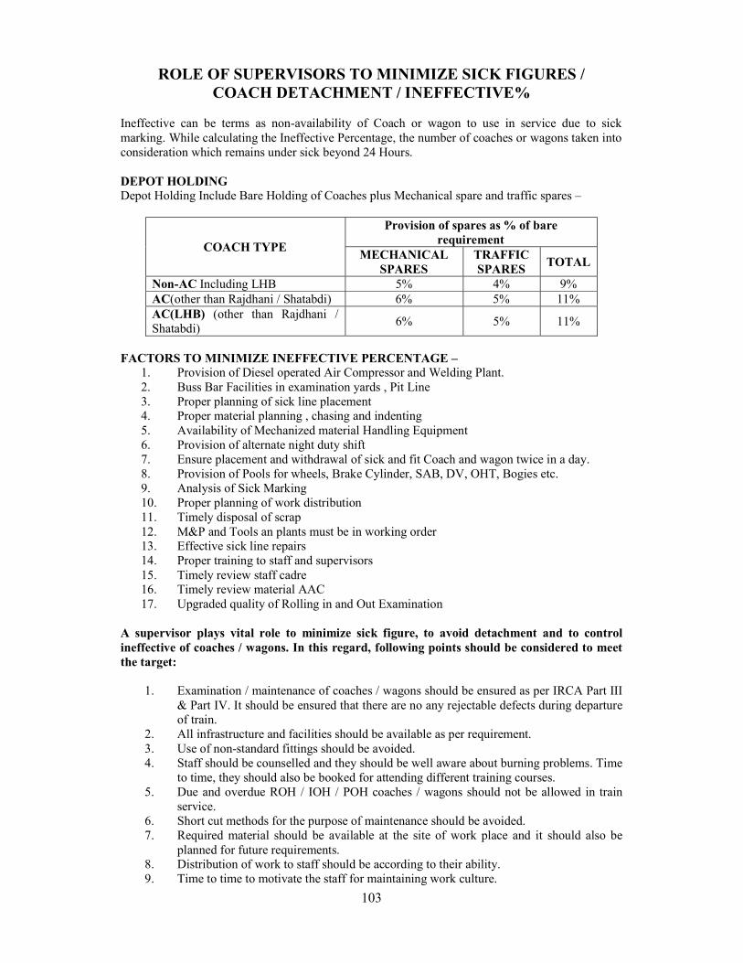
103
ROLE OF SUPERVISORS TO MINIMIZE SICK FIGURES / COACH DETACHMENT / INEFFECTIVE%
Ineffective can be terms as non-availability of Coach or wagon to use in service due to sick marking. While calculating the Ineffective Percentage, the number of coaches or wagons taken into consideration which remains under sick beyond 24 Hours. DEPOT HOLDING Depot Holding Include Bare Holding of Coaches plus Mechanical spare and traffic spares –
COACH TYPE
Provision of spares as % of bare requirement
MECHANICAL SPARES
TRAFFIC SPARES
TOTAL
Non-AC Including LHB 5% 4% 9% AC(other than Rajdhani / Shatabdi) 6% 5% 11% AC(LHB) (other than Rajdhani / Shatabdi)
6% 5% 11%
FACTORS TO MINIMIZE INEFFECTIVE PERCENTAGE –
1. Provision of Diesel operated Air Compressor and Welding Plant. 2. Buss Bar Facilities in examination yards , Pit Line 3. Proper planning of sick line placement 4. Proper material planning , chasing and indenting 5. Availability of Mechanized material Handling Equipment 6. Provision of alternate night duty shift 7. Ensure placement and withdrawal of sick and fit Coach and wagon twice in a day. 8. Provision of Pools for wheels, Brake Cylinder, SAB, DV, OHT, Bogies etc. 9. Analysis of Sick Marking 10. Proper planning of work distribution 11. Timely disposal of scrap 12. M&P and Tools an plants must be in working order 13. Effective sick line repairs 14. Proper training to staff and supervisors 15. Timely review staff cadre 16. Timely review material AAC 17. Upgraded quality of Rolling in and Out Examination
A supervisor plays vital role to minimize sick figure, to avoid detachment and to control ineffective of coaches / wagons. In this regard, following points should be considered to meet the target:
1. Examination / maintenance of coaches / wagons should be ensured as per IRCA Part III & Part IV. It should be ensured that there are no any rejectable defects during departure of train.
2. All infrastructure and facilities should be available as per requirement. 3. Use of non-standard fittings should be avoided. 4. Staff should be counselled and they should be well aware about burning problems. Time
to time, they should also be booked for attending different training courses. 5. Due and overdue ROH / IOH / POH coaches / wagons should not be allowed in train
service. 6. Short cut methods for the purpose of maintenance should be avoided. 7. Required material should be available at the site of work place and it should also be
planned for future requirements. 8. Distribution of work to staff should be according to their ability. 9. Time to time to motivate the staff for maintaining work culture.
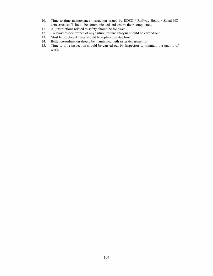
104
10. Time to time maintenance instruction issued by RDSO / Railway Board / Zonal HQ concerned staff should be communicated and ensure their compliance.
11. All instructions related to safety should be followed. 12. To avoid re-occurrence of any failure, failure analysis should be carried out. 13. Must be Replaced items should be replaced in due time. 14. Better co-ordination should be maintained with sister departments. 15. Time to time inspection should be carried out by Inspectors to maintain the quality of
work.
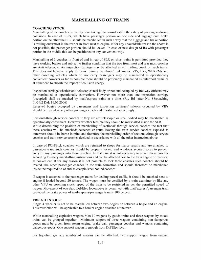
105
MARSHALLING OF TRAINS COACHING STOCK: Marshalling of the coaches is mainly done taking into consideration the safety of passengers during collisions. In case of SLRs, which have passenger portion on one side and luggage cum brake portion on the other the SLR should be marshalled in such a way that the luggage and brake portion is trailing outermost in the rear or in front next to engine. If for any unavoidable reason the above is not possible, the passenger portion should be locked. In case of new design SLRs with passenger portion in the middle this can be positioned in any convenient way. Marshalling of 3 coaches in front of and in rear of SLR on short trains is permitted provided they have working brakes and subject to further condition that the two front most and rear most coaches are Anti telescopic. An inspection carriage may be attached as 4th trailing coach on such trains. This does not however apply to trains running mainlines/trunk routes. VPs, LRs, WLRRMs and other coaching vehicles which do not carry passengers may be marshalled as operationally convenient however as far as possible these should be preferably marshalled as outermost vehicles at either end to absorb the impact of collision energy. Inspection carriage whether anti telescopic/steel body or not and occupied by Railway officers may be marshalled as operationally convenient. However not more than one inspection carriage (occupied) shall be attached by mail/express trains at a time. (Rly Bd letter No. 88/coaching 01/34/2 Dtd: 16.06.2006) Reserved bogies occupied by passengers and inspection carriages/ saloons occupied by VIPs should be treated as any other passenger coach and marshalled accordingly.
Sectional/through service coaches if they are ant telescopic or steel bodied may be marshalled as operationally convenient. However whether feasible they should be marshalled inside the SLR. While determining the position of marshalling of sectional/ through service coaches the fact that these coaches will be attached/ detached en-route leaving the train service coaches exposed as outermost should be borne in mind and therefore the marshalling order of sectional/through service coaches and train service coaches decided in accordance with all the other instruction above. In case of POH/Sick coaches which are returned to shops for major repairs and are attached to passenger train, such coaches should be properly locked and windows secured so as to prevent entry of any passenger into these coaches. In that case it is not necessary to attach these coaches according to safety marshalling instructions and can be attached next to the train engine or rearmost as convenient. If for any reason it is not possible to lock these coaches such coaches should be treated like other passenger coaches in the train formation and should therefore be marshalled inside the required no of anti-telescopic/steel bodied coaches. If wagon is attached to the passenger trains for dealing parcel traffic, it should be attached next to engine if loaded beyond 20 tonnes. The wagon must be certified by a train examiner by like any other VPU or coaching stock, speed of the train to be restricted as per the permitted speed of wagon. Movement of one dead Dsl/Elec locomotive is permitted with mail/express/passenger train provided the brake power of mail/express/passenger train is 100 percent. FREIGHT STOCK: Single 4 wheeler is not to be marshalled between two bogies or between a bogie and an engine. This restriction will be applicable to a banker engine attached at the rear. While marshalling explosive wagons Max 10 wagons by goods trains and three wagons by mixed trains can be grouped together. Minimum support of three wagons containing non dangerous goods must be given from steam engine, brake van, passenger coaches and wagons containing dangerous goods. One support wagon is enough from Dsl/Elec loco. For liquefied gas any number of wagons can be attached, two support wagon from engine,
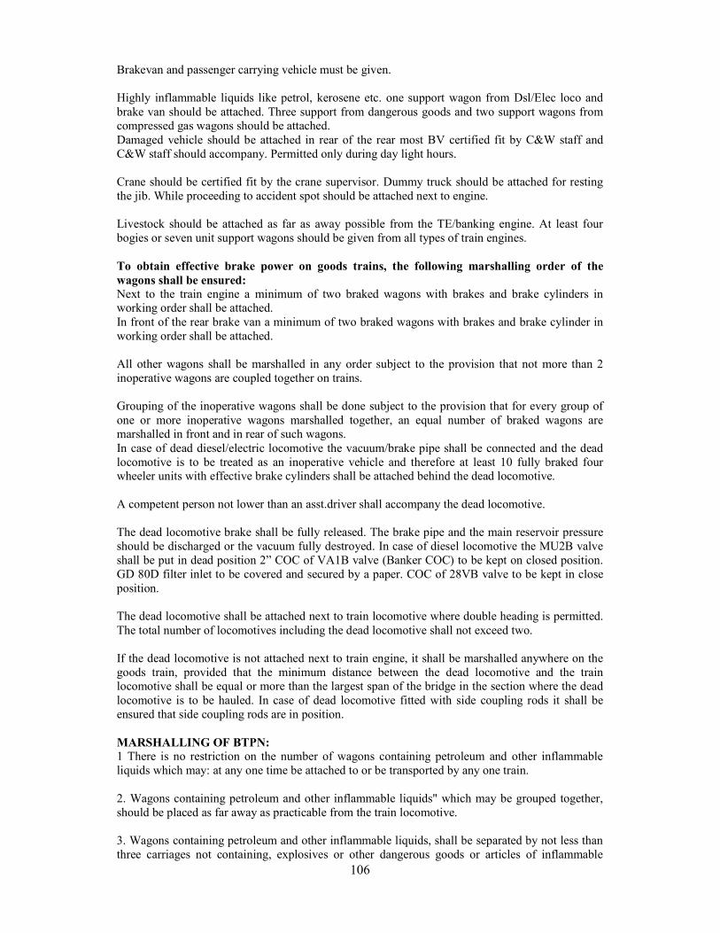
106
Brakevan and passenger carrying vehicle must be given. Highly inflammable liquids like petrol, kerosene etc. one support wagon from Dsl/Elec loco and brake van should be attached. Three support from dangerous goods and two support wagons from compressed gas wagons should be attached. Damaged vehicle should be attached in rear of the rear most BV certified fit by C&W staff and C&W staff should accompany. Permitted only during day light hours. Crane should be certified fit by the crane supervisor. Dummy truck should be attached for resting the jib. While proceeding to accident spot should be attached next to engine. Livestock should be attached as far as away possible from the TE/banking engine. At least four bogies or seven unit support wagons should be given from all types of train engines. To obtain effective brake power on goods trains, the following marshalling order of the wagons shall be ensured: Next to the train engine a minimum of two braked wagons with brakes and brake cylinders in working order shall be attached. In front of the rear brake van a minimum of two braked wagons with brakes and brake cylinder in working order shall be attached. All other wagons shall be marshalled in any order subject to the provision that not more than 2 inoperative wagons are coupled together on trains. Grouping of the inoperative wagons shall be done subject to the provision that for every group of one or more inoperative wagons marshalled together, an equal number of braked wagons are marshalled in front and in rear of such wagons. In case of dead diesel/electric locomotive the vacuum/brake pipe shall be connected and the dead locomotive is to be treated as an inoperative vehicle and therefore at least 10 fully braked four wheeler units with effective brake cylinders shall be attached behind the dead locomotive. A competent person not lower than an asst.driver shall accompany the dead locomotive. The dead locomotive brake shall be fully released. The brake pipe and the main reservoir pressure should be discharged or the vacuum fully destroyed. In case of diesel locomotive the MU2B valve shall be put in dead position 2” COC of VA1B valve (Banker COC) to be kept on closed position. GD 80D filter inlet to be covered and secured by a paper. COC of 28VB valve to be kept in close position. The dead locomotive shall be attached next to train locomotive where double heading is permitted. The total number of locomotives including the dead locomotive shall not exceed two. If the dead locomotive is not attached next to train engine, it shall be marshalled anywhere on the goods train, provided that the minimum distance between the dead locomotive and the train locomotive shall be equal or more than the largest span of the bridge in the section where the dead locomotive is to be hauled. In case of dead locomotive fitted with side coupling rods it shall be ensured that side coupling rods are in position. MARSHALLING OF BTPN: 1 There is no restriction on the number of wagons containing petroleum and other inflammable liquids which may: at any one time be attached to or be transported by any one train. 2. Wagons containing petroleum and other inflammable liquids" which may be grouped together, should be placed as far away as practicable from the train locomotive. 3. Wagons containing petroleum and other inflammable liquids, shall be separated by not less than three carriages not containing, explosives or other dangerous goods or articles of inflammable
107
nature from:-
The train locomotive provided that when an electric (traction) or diesel (electric) locomotive is used, one such carriage need intervene between the wagons containing petroleum and other inflammable liquids and the locomotive.
The passenger carriages or the brake-van, provided that when an electric (traction) or diesel (electric) locomotive is used, instead of three such carriages, only one carriage not containing explosives or other dangerous goods or article of inflammable nature may be attached between the brake-van and the last tank wagon, containing petroleum or other inflammable liquid.
Any other carriage containing explosives or other dangerous goods or articles of inflammable nature.
Wagon containing petroleum and other inflammable liquids shall be close coupled to the adjoining carriages and to each other.
Note: The provision relating to precautions to be observed during marshalling shall also apply to the empty tank wagons.
108
WHEEL IMPACT LOAD DETECTOR )WILD(
What is WILD:- The WILD is the electronic data collection device that insure vertical wheel forces via rail
mounted strain gauge. The WILD measures impact forces caused by damaged wheel in earlier stage which can lead
to axle box failure. WILD gives alarm on excessive wheel impact and Maintenance crew use this information to
plan & perform replacement of wheel before any service interruption. WILD continually monitors rail vehicle wheel health to ensure safe and productive train
operation. Turning Principle: Strain gauge mounted on rail work as wheel sensor, it weights the wheel load as it pass over from it and defect skid flat in the wheels. A wheel with flat spots can create impact loads many times higher than the fully loaded weight of the car it carries and cause serious damage to the rail road. Why is wild needed?
Defective rolling stock produce high impact load. These loads over a prolong period of time lead to rail/wagon failure, wheel bearing failure. WILD measures the impact load independent of the cause. WILD system assist the railway Engineer to the defective rolling stock immediately. Reduce service failure and unplanned maintenance cost of rolling Stocks and Tracks. WILD is used to catch the defects in the early stage and thereby protecting rail infrastructure
and avoid catastrophic failures. Defects that can cause High Impact Load –
Uneven loading Coil Spring weak Shelled Tread Friction Liner broken Snubber Spring broken Axle Box canting PU/CC/EM pad shifted/pressed/perished
Signal Conditioning and Data Acquisition Unit Signals from strain gauges are connected to signal conditioning unit. There is inbuilt surge protection to meet harsh field condition. Real time embedded controller analyzes the condition of signal and prepares the summary report for publishing in the website. System Capabilities
Count number of axles from various measurement channels. Measure average dynamic wheel load for all wheels. Determines maximum dynamic wheel load for all point of contact. Calculate speed of each axle and average speed of the train. Identifies and counts defective wheels as per specified thresholds and rates them according
to the severity of defect. Point out exact position of defective wheel from loco for easy examination. Identifies and count number of engines coaches/wagon/brake van. Operate 24*7 without any human assistance. Transmits Run reports to a central service that can be accessed by simple web Browser. Can operate from a low speed to 80 KMPH.
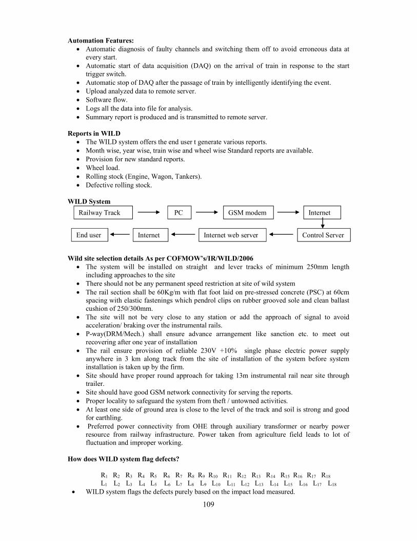
109
Automation Features: Automatic diagnosis of faulty channels and switching them off to avoid erroneous data at
every start. Automatic start of data acquisition (DAQ) on the arrival of train in response to the start
trigger switch. Automatic stop of DAQ after the passage of train by intelligently identifying the event. Upload analyzed data to remote server. Software flow. Logs all the data into file for analysis. Summary report is produced and is transmitted to remote server.
Reports in WILD
The WILD system offers the end user t generate various reports. Month wise, year wise, train wise and wheel wise Standard reports are available. Provision for new standard reports. Wheel load. Rolling stock (Engine, Wagon, Tankers). Defective rolling stock.
WILD System
Wild site selection details As per COFMOW’s/IR/WILD/2006
The system will be installed on straight and lever tracks of minimum 250mm length including approaches to the site
There should not be any permanent speed restriction at site of wild system The rail section shall be 60Kg/m with flat foot laid on pre -stressed concrete (PSC) at 60cm
spacing with elastic fastenings which pendrol clips on rubber grooved sole and clean ballast cushion of 250/300mm.
The site will not be very close to any station or add the approach of signal to avoid acceleration/ braking over the instrumental rails.
P-way(DRM/Mech.) shall ensure advance arrangement like sanction etc. to meet out recovering after one year of installation
The rail ensure provision of reliable 230V +10% single phase electric power supply anywhere in 3 km along track from the site of installation of the system before system installation is taken up by the firm.
Site should have proper round approach for taking 13m instrumental rail near site through trailer.
Site should have good GSM network connectivity for serving the reports. Proper locality to safeguard the system from theft / untowned activities. At least one side of ground area is close to the level of the track and soil is strong and good
for earthling. Preferred power connectivity from OHE through auxiliary transformer or nearby power
resource from railway infrastructure. Power taken from agriculture field leads to lot of fluctuation and improper working.
How does WILD system flag defects? R1 R2 R3 R4 R5 R6 R7 R8 R9 R10 R11 R12 R13 R14 R15 R16 R17 R18 L1 L2 L3 L4 L5 L6 L7 L8 L9 L10 L11 L12 L13 L14 L15 L16 L17 L18 WILD system flags the defects purely based on the impact load measured.
Railway Track PC GSM modem Internet
Control Server Internet web server Internet End user

110
The limits are set by RDSO/RB. Current limits
1. > 20T maintenance alarm or ILF > 2.0 < 4.5 2. > 30T critical alarm ILF ≥ 4.5
Where, ILF: impact load factor
The systems however feature a facility for end user to set the limits as well.
LILF ) Left Impact Load Factor) =
RILF (Right Impact Load Factor) =
Calculation ( WILD ii VER. 3.6 CHANNEL)
Remarks Left Load Right Load Remarks L1 3.5 R1 3.4 L2 3.2 R2 3.3
Third left MAX L3 9.8 R3 2.9 L4 2.7 R4 3.0 L5 3.1 R5 3.2 L6 2.9 R6 3 L7 3.1 R7 3.2 L8 3.4 R8 3.3
First left MAX L9 17.1 R9 11.2 First Right MAX L10 6.1 R10 4.7 Third Right MAX L11 3.1 R11 3.2 L12 2.9 R12 3.1
Second left MAX L13 12.4 R13 10.8 Second Right MAX
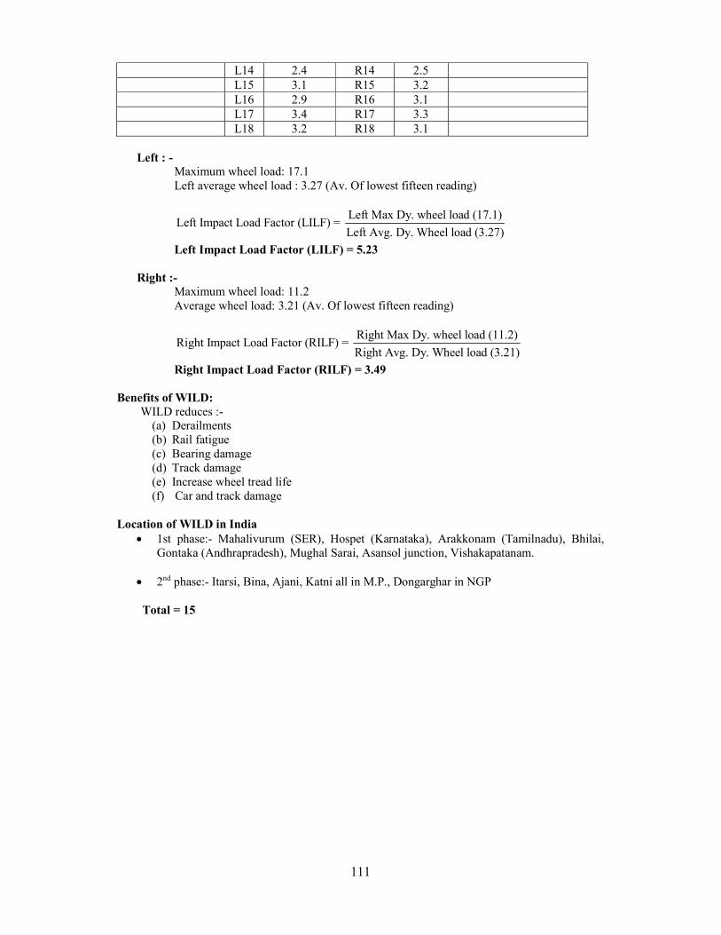
111
Left : - Maximum wheel load: 17.1 Left average wheel load : 3.27 (Av. Of lowest fifteen reading)
Left Max Dy. wheel load (17.1)
Left Impact Load Factor (LILF) = Left Avg. Dy. Wheel load (3.27)
Left Impact Load Factor (LILF) = 5.23
Right :- Maximum wheel load: 11.2 Average wheel load: 3.21 (Av. Of lowest fifteen reading)
Right Max Dy. wheel load (11.2)
Right Impact Load Factor (RILF) = Right Avg. Dy. Wheel load (3.21)
Right Impact Load Factor (RILF) = 3.49 Benefits of WILD: WILD reduces :-
(a) Derailments (b) Rail fatigue (c) Bearing damage (d) Track damage (e) Increase wheel tread life (f) Car and track damage
Location of WILD in India
1st phase:- Mahalivurum (SER), Hospet (Karnataka), Arakkonam (Tamilnadu), Bhilai, Gontaka (Andhrapradesh), Mughal Sarai, Asansol junction, Vishakapatanam.
2nd phase:- Itarsi, Bina, Ajani, Katni all in M.P., Dongarghar in NGP Total = 15
L14 2.4 R14 2.5 L15 3.1 R15 3.2 L16 2.9 R16 3.1 L17 3.4 R17 3.3 L18 3.2 R18 3.1
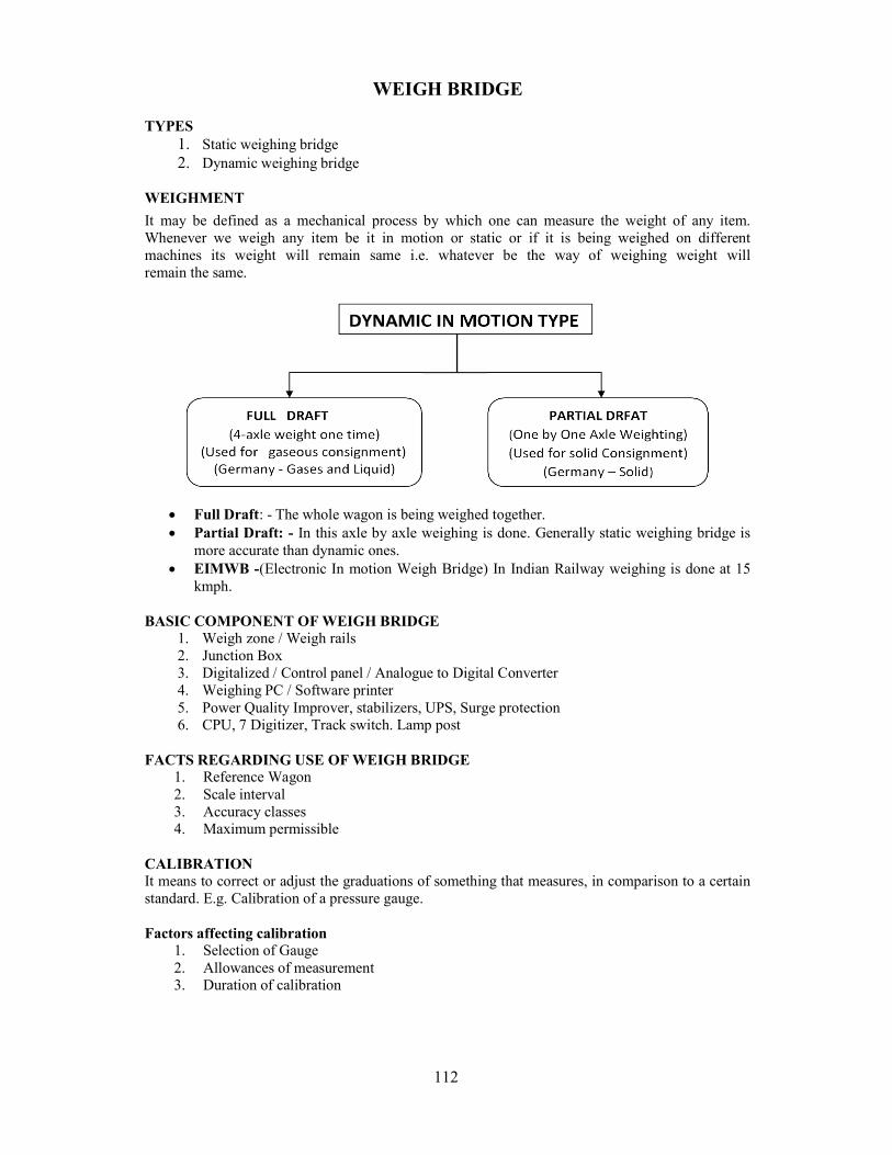
112
WEIGH BRIDGE TYPES
1. Static weighing bridge 2. Dynamic weighing bridge
WEIGHMENT
It may be defined as a mechanical process by which one can measure the weight of any item. Whenever we weigh any item be it in motion or static or if it is being weighed on different machines its weight will remain same i.e. whatever be the way of weighing weight will remain the same.
Full Draft: - The whole wagon is being weighed together. Partial Draft: - In this axle by axle weighing is done. Generally static weighing bridge is
more accurate than dynamic ones. EIMWB -(Electronic In motion Weigh Bridge) In Indian Railway weighing is done at 15
kmph. BASIC COMPONENT OF WEIGH BRIDGE
1. Weigh zone / Weigh rails 2. Junction Box 3. Digitalized / Control panel / Analogue to Digital Converter 4. Weighing PC / Software printer 5. Power Quality Improver, stabilizers, UPS, Surge protection 6. CPU, 7 Digitizer, Track switch. Lamp post
FACTS REGARDING USE OF WEIGH BRIDGE
1. Reference Wagon 2. Scale interval 3. Accuracy classes 4. Maximum permissible
CALIBRATION It means to correct or adjust the graduations of something that measures, in comparison to a certain standard. E.g. Calibration of a pressure gauge. Factors affecting calibration
1. Selection of Gauge 2. Allowances of measurement 3. Duration of calibration
113
Factors affecting Weighment 1. Calibration 2. Preciseness 3. Accuracy 4. Least count
RF WAGON It is that wagon whose weight is known and which is being used to test IN MOTION WEIGH BRIDGE. In other words it is that weight which is being used to test and improve Weigh Bridge. SCALE INTERVAL It is the least count between the two graduations on the weighing scale. It is also known IMB’s scale interval in other words. In Indian Railway IMB’s scale interval for 120 ton is 100 kg. ACCURACY CLASSES OF MEASUREMENT AND MAXIMUM PERMISSIBLE ERROR
Accuracy Class Percentage of single wagon or total train as appropriate
During Verification During Inspection
0.2 ±0.10% ±0.20%
0.5 ±0.25% ±0.50%
1 ±0.50% ±1.00%
2 ±1.00% ±2.00%
BACK LOAD TEST Run 75% train over the weighing instrument than stop the train and reverse the train & than check the reading both as same or not. It called back load test or anti roll trade test. LOAD CELL
It is an electronic device which is classified under force transducer. It converts force or weight into electronic signal.
Its advantage is that it is not mechanized. It maintains accuracy of 0.03%to 0.025%. A strain gauge is attached to load cell. When no load goes into weighing zone then in wheat stone bridge the strain gauge provides equal resistance and when load comes in weighing zone then bridge generates signal in mV.
This bridge circuit also send electronic signal to CPU which is according to the load on strain gauge. The strain gauge measures shear stress.
Function of DIO Card: It senses the signal from track, switches and send out put to lamp post and alarm. Function of OP Card: It provides power through switches, contents lamp post & track switches. Function of OPTO Card: It provides isolation of track. Switch inputs and outputs to lamp post. ROLE OF MECHANICAL DEPARTMENT: The Mechanical Dept. shall be responsible for entering into Annual Maintenance Contract (AMC) and its satisfactory execution with the original equipment supplier (OEM) for the weigh bridge as per extant Railway Board’s guideline subject. ADRM shall nominate an AME or SSE of Mechanical dept. available at the nearest station for liaison with the supplier for preventive and break down maintenance during the warranty period as well as during the annual maintenance contract. The nominated official of the Mechanical Department shall co-ordinate with other departments responsible for maintenance and ensures that
114
it is maintained properly. The nominated official of Mechanical Dept. shall see that break down register is being maintained properly by weighbridge incharge. INSTRUCTIONS RELATED TO TESTING OF WEIGHBRIDGES The electric weighbridge shall be tested with duly calibrated test wagon every month, as per procedure prescribed by the manufacturer and a certificate given to a Coml. Dept. jointly signed by the weighbridge in charge and the officials of the Mechanical Dept. In addition to testing with the test wagon, repeatability test of the Electronic in-motion shall be carried out after every three months along with the Service Engineer of the manufacturer as per procedure prescribed by the manufacturer. In case any major repair is carried out on the weighbridge by the Service Engineer retesting will be done at the time of re-commissioning. The officials of the Mechanical Dept. nominated shall ensure that the weigh bridge is got tested by Weight and Measurement Dept. of the State every year by the supplier as a part of the AMC contract. The supplier shall carry out required adjustment, if any, during last testing and covering of the digitizer panel shall be locked and sealed. This cover shall only be opened by the ‘Service Engineer’ of the supplier after obtaining key from the officials of the Mechanical Department after having made an entry in the maintenance register. Whenever a call is received by officials of Mechanical Dept. from weigh bridge in-charge that the weighbridge is out of order or behaving erratically, staff must be sent to study the defect and call the Service Engineer of the weigh bridge supplier for attending to the defects for which proper record shall be maintained. The maintenance of the mini generating set provided to cater for the load of the weigh bridge and lightning equipment shall also be carried out by mechanical department through maintenance contract, departmentally or from market sources as per requirement.
115
LAYOUT OF COACHING DEPOT INTRODUCTION Railways are made up of complex mechanical and electrical systems and there hundreds of thousands of moving parts. If a railway service is not to be reliable, the equipment must be kept in good working order and regular maintenance is the essential ingredient to achieve this. A railway will not survive for long as a viable operation if it is allowed to deteriorate because of lack of maintenance.
Layout shows the general arrangement of infrastructure, machines and other equipments used in the depot for maintenance and repair work. Systematic planning of Space, Machinery, Tools & Plants etc. To handle the given work load and achieving optimum efficiency from available resources is the basic purpose of optimum “Layout”. CLASSIFICATION OF COACHING DEPOT 1) Depot classification is dependent upon the number of based coaches.
Upto 100 coaches - Minor Depot 100 to 250 coaches - Medium Depot Above 250 coaches - Major Depot
2) Base Coaches:- It means coaches utilised in primary maintained trains. However for designing coaching depot layout, effective base holding is equal to the sum of primary based coaches plus half of the secondary coaches.
3) Number of trains for maintenance:- It includes primary base train, secondary maintenance and train returning from yard/platform etc.
4) Type of Stock:- Additional/specific facilities required for newer stock like LHB etc. 5) Level of mechanisation required:- Mechanised cleaning will high pressure jet cleaning
machines, vacuum cleaner, scrubbers etc. 6) Statutory requirements regarding environmental conservation, pollution control, desired level
of lighting etc. 7) Material handling and movement of material. 8) Safety of staff. 9) Reduction in maintenance time- provision of EOT cranes, jacks, construction of washing lines
to encourage on line fitment. FACILITIES TO BE PROVIDED IN COACHING DEPOT:
A. No of Line: i. In Sick Line:-The design should be based on 4% of the based coaches. Max. Number
of coaches to be placed per line should be limited to 4. No. of lines = 4% of based coaches/4
ii. Washing line:-Normally two primary & one secondary train can be planned for maintenance on washing line in 24 hrs.
No. of washing line = No. of trains/3 B. Covered Accommodation on Sick Line:- It should be sufficient to hold 4% of the base
coaches. C. Bay Width:-
i. Sick Line:- Each bay should 15 metre wide & should cover two lines. The track centre should be 7.5 metre apart.
ii. Washing Line:- The track centre should be 6922 mm. D. Examination Pits
i. On Sick Line:- It should be provided on half of entire length of the each line. The depth should not be less than 930 mm from the rail top.
ii. Washing Line:- It should be provided on entire length of washing line. It should be 960 mm deep and 1223 mm wide. The width of the rail bed should be 950 mm. The examination pit should be provided with cat walk on either side. The middle & side catwalk should be 3272 mm and 1786 mm respectively. The thickness of catwalk should be 120 mm. The gap between coach body & catwalk should be 200 mm & height of the catwalk should be 1880 mm from the ground floor. The catwalk should be RCC.
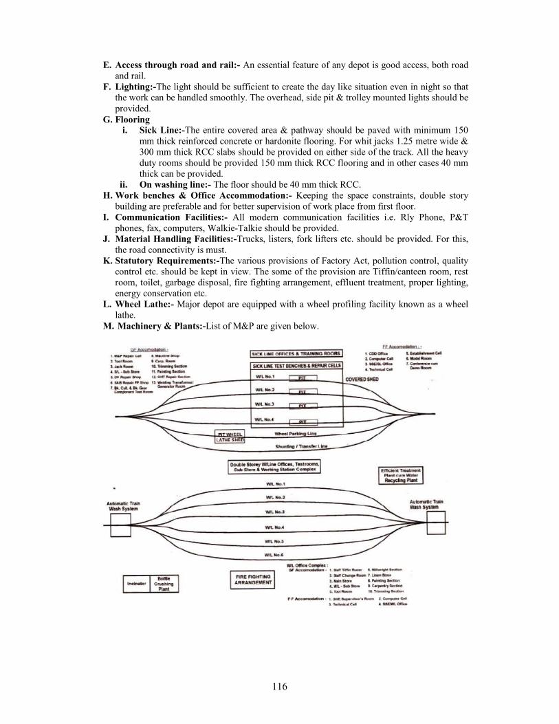
116
E. Access through road and rail:- An essential feature of any depot is good access, both road
and rail. F. Lighting:-The light should be sufficient to create the day like situation even in night so that
the work can be handled smoothly. The overhead, side pit & trolley mounted lights should be provided.
G. Flooring i. Sick Line:-The entire covered area & pathway should be paved with minimum 150
mm thick reinforced concrete or hardonite flooring. For whit jacks 1.25 metre wide & 300 mm thick RCC slabs should be provided on either side of the track. All the heavy duty rooms should be provided 150 mm thick RCC flooring and in other cases 40 mm thick can be provided.
ii. On washing line:- The floor should be 40 mm thick RCC. H. Work benches & Office Accommodation:- Keeping the space constraints, double story
building are preferable and for better supervision of work place from first floor. I. Communication Facilities:- All modern communication facilities i.e. Rly Phone, P&T
phones, fax, computers, Walkie-Talkie should be provided. J. Material Handling Facilities:-Trucks, listers, fork lifters etc. should be provided. For this,
the road connectivity is must. K. Statutory Requirements:-The various provisions of Factory Act, pollution control, quality
control etc. should be kept in view. The some of the provision are Tiffin/canteen room, rest room, toilet, garbage disposal, fire fighting arrangement, effluent treatment, proper lighting, energy conservation etc.
L. Wheel Lathe:- Major depot are equipped with a wheel profiling facility known as a wheel lathe.
M. Machinery & Plants:-List of M&P are given below.
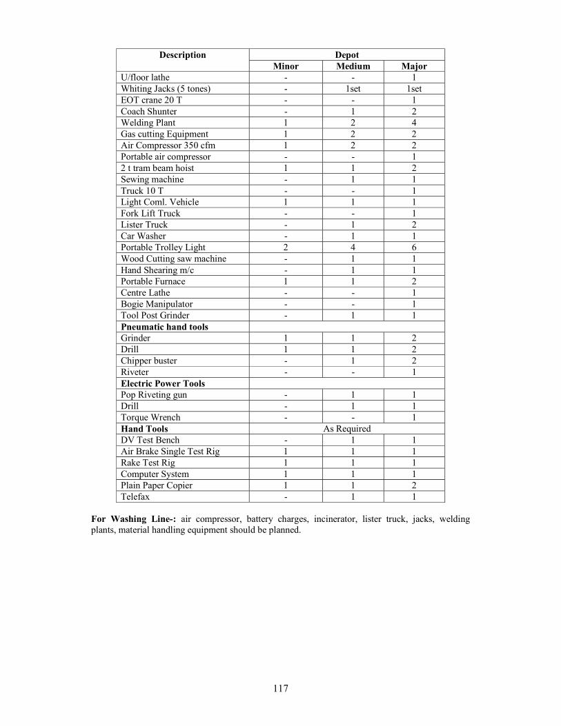
117
Description Depot Minor Medium Major
U/floor lathe - - 1 Whiting Jacks (5 tones) - 1set 1set EOT crane 20 T - - 1 Coach Shunter - 1 2 Welding Plant 1 2 4 Gas cutting Equipment 1 2 2 Air Compressor 350 cfm 1 2 2 Portable air compressor - - 1 2 t tram beam hoist 1 1 2 Sewing machine - 1 1 Truck 10 T - - 1 Light Coml. Vehicle 1 1 1 Fork Lift Truck - - 1 Lister Truck - 1 2 Car Washer - 1 1 Portable Trolley Light 2 4 6 Wood Cutting saw machine - 1 1 Hand Shearing m/c - 1 1 Portable Furnace 1 1 2 Centre Lathe - - 1 Bogie Manipulator - - 1 Tool Post Grinder - 1 1 Pneumatic hand tools Grinder 1 1 2 Drill 1 1 2 Chipper buster - 1 2 Riveter - - 1 Electric Power Tools Pop Riveting gun - 1 1 Drill - 1 1 Torque Wrench - - 1 Hand Tools As Required DV Test Bench - 1 1 Air Brake Single Test Rig 1 1 1 Rake Test Rig 1 1 1 Computer System 1 1 1 Plain Paper Copier 1 1 2 Telefax - 1 1
For Washing Line-: air compressor, battery charges, incinerator, lister truck, jacks, welding plants, material handling equipment should be planned.
Related Documents

![Great North Western Railway Dated [ ] Between NETWORK …orr.gov.uk/__data/assets/pdf_file/0015/2751/s17-alliance-draft... · Doc # 435601.01. Great North Western Railway. TRACK ACCESS](https://static.cupdf.com/doc/110x72/5b51f75c7f8b9a056a8cca7e/great-north-western-railway-dated-between-network-orrgovukdataassetspdffile00152751s17-alliance-draft.jpg)